geotechnical terranox dth hammers - home - terraroc
TRANSCRIPT

GeotechnicalTerranox DTH hammersTerranox 3, 4, 5, 6, 8Safety, operating instructions and spare parts list

2
ContentsIntroduction ��������������������������������������������������������������������������������������������������������4Measurements ������������������������������������������������������������������������������������������������������������������������������������������������������������������������������������ . 4
Abbreviations ���������������������������������������������������������������������������������������������������������������������������������������������������������������������������������������� 4
Safety regulations ��������������������������������������������������������������������������������������������5Personal precautions and qualifications ������������������������������������������������������������������������5Hoisting and transport ����������������������������������������������������������������������������������������������������������������������������������������������������������������������5
Storage, repair, maintenance and disposal �������������������������������������������������������������������������������������������������������������������������5
Operation ���������������������������������������������������������������������������������������������������������������������������������������������������������������������������������������������������5
Personal protective equipment ��������������������������������������������������������������������������������������������������������������������������������������������������5
Drugs, alcohol or medication �������������������������������������������������������������������������������������������������������������������������������������������������������5
Safety area ������������������������������������������������������������������������������������������������������������������������������������5
Hoisting and transport ������������������������������������������������������������������������������������������������������������6
Operation, precautions �����������������������������������������������������������������������������������������������������������6
Maintenance, precautions �����������������������������������������������������������������������������������������������������7
Additional safety instructions for the Terranox DTH hammer� �����������������������������8Follow instructions ������������������������������������������������������������������������������������������������������������������������������������������������������������������������������8
Keep DTH hammer in good working condition ����������������������������������������������������������������������������������������������������������������8
Loose parts ����������������������������������������������������������������������������������������������������������������������������������������������������������������������������������������������8
Live air ���������������������������������������������������������������������������������������������������������������������������������������������������������������������������������������������������������8
Air pressure ����������������������������������������������������������������������������������������������������������������������������������������������������������������������������������������������8
Do not work in trench ������������������������������������������������������������������������������������������������������������������������������������������������������������������������8
Check laws and regulations ����������������������������������������������������������������������������������������������������������������������������������������������������������8
Observe environmental protection regulations ���������������������������������������������������������������������������������������������������������������8
Installation and operation ����������������������������������������������������������������������������9General information �����������������������������������������������������������������������������������������������������������������9Description �����������������������������������������������������������������������������������������������������������������������������������������������������������������������������������������������9
Setting up the DTH hammer ������������������������������������������������������������������������������������������������9Choke selection setup ����������������������������������������������������������������������������������������������������������������������������������������������������������������������9
Bailing velocity requirements ���������������������������������������������������������������������������������������������������������������������������������������������������10
Bit installation ��������������������������������������������������������������������������������������������������������������������������������������������������������������������������������������10
Used bit and chuck ��������������������������������������������������������������������������������������������������������������������������������������������������������������������������10
Makeup torque and backhead closure �������������������������������������������������������������������������������������������������������������������������������10
Drill Lubrication����������������������������������������������������������������������������������������������������������������������� 10Lubrication guidelines and specifications ������������������������������������������������������������������������������������������������������������������������10
Lubricators ��������������������������������������������������������������������������������������������������������������������������������������������������������������������������������������������10
Lubrication check ������������������������������������������������������������������������������������������������������������������������������������������������������������������������������ 11
Water injection ������������������������������������������������������������������������������������������������������������������������������������������������������������������������������������� 11
Drill operation ��������������������������������������������������������������������������������������������������������������������������11Drilling with foam ������������������������������������������������������������������������������������������������������������������������������������������������������������������������������� 11
Collaring ��������������������������������������������������������������������������������������������������������������������������������������������������������������������������������������������������� 11
Rotation speed ������������������������������������������������������������������������������������������������������������������������������������������������������������������������������������ 11
Rotation Torque ���������������������������������������������������������������������������������������������������������������������������������������������������������������������������������� 12
Feed force (hold down and hold back) ������������������������������������������������������������������������������������������������������������������������������� 12
Hole cleaning, flushing and dust suppression ��������������������������������������������������������������������������������������������������������������� 12
Dry drilling ��������������������������������������������������������������������������������������������������������������������������������������������������������������������������������������������� 12
Wet drilling �������������������������������������������������������������������������������������������������������������������������������������������������������������������������������������������� 12
Bit changing �������������������������������������������������������������������������������������������������������������������������������12Removing the drill bit ��������������������������������������������������������������������������������������������������������������������������������������������������������������������� 12
Removing the bit with percussion only������������������������������������������������������������������������������������������������������������������������������ 13
Process instructions �������������������������������������������������������������������������������������������������������������������������������������������������������������������������13
Maintenance and repair ����������������������������������������������������������������������������� 14Follow instructions ����������������������������������������������������������������������������������������������������������������������������������������������������������������������������14
Tools required for DTH service and repair �������������������������������������������������������������������������������������������������������������������������14
Assembly tools ������������������������������������������������������������������������������������������������������������������������������������������������������������������������������������14

3
DTH service ��������������������������������������������������������������������������������������������������������������������������������15
Terranox disassembly �����������������������������������������������������������������������������������������������������������15
Terranox inspection ��������������������������������������������������������������������������������������������������������������� 16
Terranox assembly ����������������������������������������������������������������������������������������������������������������� 18Exhaust tube replacement and installation ��������������������������������������������������������������������������������������������������������������������� 21
Bits ����������������������������������������������������������������������������������������������������������������������� 21Selecting the right bit �����������������������������������������������������������������������������������������������������������21
Drill bits – standard assortment ���������������������������������������������������������������������������������������21Convex front ����������������������������������������������������������������������������������������������������������������������������������������������������������������������������������������� 21
Flat front������������������������������������������������������������������������������������������������������������������������������������������������������������������������������������������������ 22
SpeedBit �������������������������������������������������������������������������������������������������������������������������������������������������������������������������������������������������22
Concave front ��������������������������������������������������������������������������������������������������������������������������������������������������������������������������������������22
Rocket bit �����������������������������������������������������������������������������������������������������������������������������������������������������������������������������������������������22
Bit service ���������������������������������������������������������������������������������������������������������������������������������� 23
Grinding instructions for button bits ����������������������������������������������������������������������������� 23When to regrind ���������������������������������������������������������������������������������������������������������������������������������������������������������������������������������23
Always grind broken buttons flat ��������������������������������������������������������������������������������������������������������������������������������������������23
Do not grind away too much cemented carbide ����������������������������������������������������������������������������������������������������������23
Avoid grinding the gauge ������������������������������������������������������������������������������������������������������������������������������������������������������������23
Look out for “snake skin” ��������������������������������������������������������������������������������������������������������������������������������������������������������������23
Diamond grinding wheels and cups �������������������������������������������������������������������������������������������������������������������������������������23
General and safety rules for grinding ��������������������������������������������������������������������������� 23
Troubleshooting guide ������������������������������������������������������������������������������� 24
Specifications �������������������������������������������������������������������������������������������������� 27Physical and maintenance specifications ������������������������������������������������������������������� 27General specifications ��������������������������������������������������������������������������������������������������������������������������������������������������������������������27
Operational specifications �����������������������������������������������������������������������������������������������������������������������������������������������������������27
Hammer frequence at different working pressures ���������������������������������������������������������������������������������������������������28
Air consumption at different working pressures �����������������������������������������������������������������������������������������������������������28
Air consumption and hammer frequence �������������������������������������������������������������������������������������������������������������������������28
Calculating feed force �������������������������������������������������������������������������������������������������������������������������������������������������������������������28
Calculating recomended rotation speed ��������������������������������������������������������������������������������������������������������������������������28
Service specifications���������������������������������������������������������������������������������������������������������������������������������������������������������������������29
Terranox clearance worksheet ������������������������������������������������������������������������������������������������������������������������������������������������ 30
DTH requirements �������������������������������������������������������������������������������������������������������������������31Minimum guidelines for mounting specifications ���������������������������������������������������������������������������������������������������������31
Minimum requirements for compressor capacity and pressure �������������������������������������������������������������������������31
Cross sections of the Terranox hammers ���������������������������������������������������������������������31Terranox 3 �����������������������������������������������������������������������������������������������������������������������������������������������������������������������������������������������31
Terranox 4 �����������������������������������������������������������������������������������������������������������������������������������������������������������������������������������������������31
Terranox 5 �����������������������������������������������������������������������������������������������������������������������������������������������������������������������������������������������31
Terranox 6 �����������������������������������������������������������������������������������������������������������������������������������������������������������������������������������������������31
Terranox 8 �����������������������������������������������������������������������������������������������������������������������������������������������������������������������������������������������31
Disposal and environmental instructions ��������������������������������������������������������������������31Oil and Grease ��������������������������������������������������������������������������������������������������������������������������������������������������������������������������������������31
Chemicals �����������������������������������������������������������������������������������������������������������������������������������������������������������������������������������������������31
Dust �������������������������������������������������������������������������������������������������������������������������������������������������������������������������������������������������������������31
Metals (steel, aluminum, etc�) ����������������������������������������������������������������������������������������������������������������������������������������������������31
Plastics and rubber ���������������������������������������������������������������������������������������������������������������������������������������������������������������������������31
Material Safety Data Sheets (MSDS/SDS) �������������������������������������������������������������������������������������������������������������������������31
Spare parts lists ��������������������������������������������������������������������������������������������� 32

4
IntroductionThese instructions are intended for operators of the TerraRoc equipment� The aim of the instructions is to provide you with knowledge of how to use the equipment in an efficient and safe way� These instructions also give you advice and tell you how to perform regular maintenance on the equipment� It does not replace thorough training of operator, it is a complement� For further information concerning service measures, please contact your nearest TerraRoc representative�
Always read these instructions carefully and make sure that you understand all of them before starting for the first time. Read this manual carefully to learn how to operate and service your down-the-hole (DTH) hammer correctly� Failure to do so could result in personal injury or equipment damage� Consult your TerraRoc Dealer if you do not understand the instructions in this manual or need additional information� This manual should be considered a permanent part of the DTH hammer, and should remain with the DTH hammer and available for reference at all times�
The owner of the equipment is granted the permission to take copies of this publication solely for internal use� It is recommended, however, to order additional copies from TerraRoc representative in order to benefit from the latest revision. We reserve the right to make changes in its products in order to improve design or performance characteristics without notice� The information in this publication is assumed to be accurate at the time of publication, but is subject to changes in order to remedy detected deficiencies or to follow changes in the product� The instructions, illustrations, and specifications in this manual are based on the latest information available at time of publication� Your DTH hammer may have improvements and options not yet contained in this manual�
Any user of this publication is requested to inform us about deficiencies found, particularly in matters concerning product safety�
Measurements
Measurements in this manual are given in both metric and English/imperial units and are used to provide additional worldwide understanding� English/imperial units are shown between parentheses ‘’( )’’�
Abbreviations
Abbreviations used throughout this manual�
acfm Actual Cubic Feet per Minute
C Centigrade
dia� Diameter
deg� Degree
F Farenheit
ft� Feet
ft�-lb Foot Pounds
gpm Gallons per Minute
in� Inches
kg Kilogram
l Liter
lbs� Pounds
lpm Liters per Minute
m Meter
mm Millimeter
mm Hg Milimeters of Mercury
m3/min Cubic Meters per Minute
psi ounds per Square Inch
psig Pounds per Square Inch Gauge Pressure
rpm Revolutions per Minute
scfm Standard Cubic Feet per Minute
Safety Alert Symbol
5
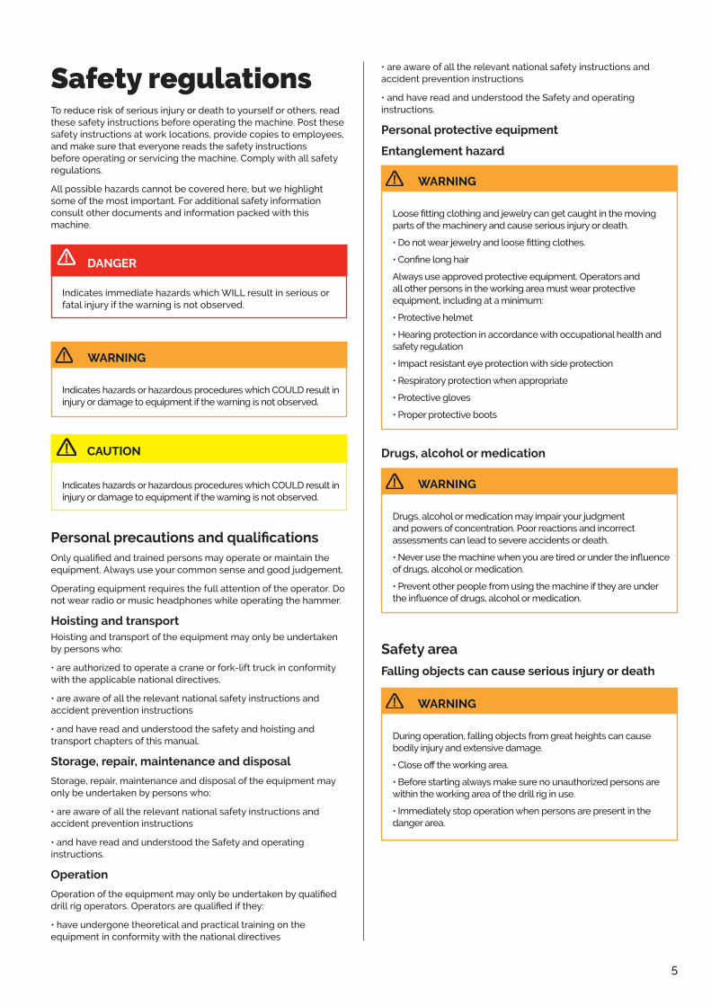
Safety regulationsTo reduce risk of serious injury or death to yourself or others, read these safety instructions before operating the machine� Post these safety instructions at work locations, provide copies to employees, and make sure that everyone reads the safety instructions before operating or servicing the machine� Comply with all safety regulations�
All possible hazards cannot be covered here, but we highlight some of the most important� For additional safety information consult other documents and information packed with this machine�
Indicates immediate hazards which WILL result in serious or fatal injury if the warning is not observed�
DANGER
Indicates hazards or hazardous procedures which COULD result in injury or damage to equipment if the warning is not observed�
WARNING
Indicates hazards or hazardous procedures which COULD result in injury or damage to equipment if the warning is not observed�
CAUTION
Personal precautions and qualificationsOnly qualified and trained persons may operate or maintain the equipment� Always use your common sense and good judgement�
Operating equipment requires the full attention of the operator� Do not wear radio or music headphones while operating the hammer�
Hoisting and transportHoisting and transport of the equipment may only be undertaken by persons who:
• are authorized to operate a crane or fork-lift truck in conformity with the applicable national directives,
• are aware of all the relevant national safety instructions and accident prevention instructions
• and have read and understood the safety and hoisting and transport chapters of this manual�
Storage, repair, maintenance and disposal
Storage, repair, maintenance and disposal of the equipment may only be undertaken by persons who:
• are aware of all the relevant national safety instructions and accident prevention instructions
• and have read and understood the Safety and operating instructions�
Operation
Operation of the equipment may only be undertaken by qualified drill rig operators. Operators are qualified if they:
• have undergone theoretical and practical training on the equipment in conformity with the national directives
• are aware of all the relevant national safety instructions and accident prevention instructions
• and have read and understood the Safety and operating instructions�
Personal protective equipment
Entanglement hazard
Loose fitting clothing and jewelry can get caught in the moving parts of the machinery and cause serious injury or death�
• Do not wear jewelry and loose fitting clothes.
• Confine long hair
Always use approved protective equipment� Operators and all other persons in the working area must wear protective equipment, including at a minimum:
• Protective helmet
• Hearing protection in accordance with occupational health and safety regulation
• Impact resistant eye protection with side protection
• Respiratory protection when appropriate
• Protective gloves
• Proper protective boots
WARNING
Drugs, alcohol or medication
Drugs, alcohol or medication may impair your judgment and powers of concentration� Poor reactions and incorrect assessments can lead to severe accidents or death�
• Never use the machine when you are tired or under the influence of drugs, alcohol or medication�
• Prevent other people from using the machine if they are under the influence of drugs, alcohol or medication.
WARNING
Safety area
Falling objects can cause serious injury or death
During operation, falling objects from great heights can cause bodily injury and extensive damage�
• Close off the working area.
• Before starting always make sure no unauthorized persons are within the working area of the drill rig in use�
• Immediately stop operation when persons are present in the danger area�
WARNING

6
Hoisting and transport
Heavy equipment can cause serious injury
• Use a sling dimensioned for the load it is to carry�
• Use only straps that are whole and intended for the load in question�
• Never use a damaged rope/sling�
• Fasten straps in lifting eyes when present�
• Always lift at the centre of gravity�
• Always make sure that nobody is under or anywhere near a suspended load or within the swing radius of the rope/sling�
• Observe great care when strapping and lifting heavy objects�
NOTICE Sling can damage components
When lifting, make sure that the sling will not damage the hydraulic hoses, mechanical components etc�
WARNING
Operation, precautions
Hydraulic oil at high pressure
• Thin jets of hydraulic oil under high pressure can penetrate the skin and cause permanent damage�
• Immediately consult a doctor if hydraulic oil has penetrated the skin�
• Never use your fingers to check for hydraulic fluid leaks.
• Keep your face away from any possible leaks�
WARNING
Underground utility lines
• Check for underground utility lines� Before starting work, remember that contact with buried utilities may cause serious injury or death� Electric line contact may cause electric shock or electrocution� Gas line contact may rupture pipe causing explosion or fire.
Fiber optic cables can blind you if you look into the laser light in them. Water line rupture may cause a flood and possible ground collapse. Before drilling, check with qualified sources to properly locate all buried utilities in and around drill path� Select a drill path that will not intersect buried utilities� Never launch a drill bit on a path toward electric, gas, or water lines until their location is known� If there is any doubt as to the location of the underground placement, have the utility company shut it off before starting any underground work and excavate to confirm its exact location.
WARNING
Dust hazard
When drilling with compressed air, the rock cuttings are carried out of the bore in the form of small cuttings, and dust, which can cause serious injury�
Some dusts, fumes or other airborne material created during use of the machine may contain chemicals known to the State of California to cause cancer and birth defects or other reproductive harm� Some examples of such chemicals are:
• Crystalline silica, cement and other masonry products�
• Arsenic and chromium from chemically-treated rubber�
• Lead from lead-based paints�
• To reduce your exposure to these chemicals, work in a well ventilated area and work with approved safety equipment, such as dust masks that are specially designed to filter out microscopic particles�
• Use a dust collector, or spray water with a water/ foam pump�
WARNING
Unexpected movement can cause serious injury
If control levers and switches are not set to neutral position, start of the machine can lead to unexpected movements and can therefore cause injury�
• ISet control levers and switches to the neutral positions prior to starting up�
WARNING
Noise hazard
High sound levels may cause permanent hearing loss�
• Use hearing protection in accordance with occupational health and safety regulations�
WARNING
Emergency situation
An emergency situation can occur due to material failure or incorrect handling�
• Stop the operation by pushing the emergency stop button or if available pull the trip wire�
• Check proper function of the rig safety equipment at least once beginning of each shift�
WARNING
7
Gas line pressurized, Explosion hazard
If the equipment comes in contact with gas lines and explosives, an explosion could occur� Explosions will lead to severe injuries or death�
• Never operate the machine in any explosive environment�
• Never use the machine near flammable materials, fumes or dust.
• Make sure that there are no undetected sources of gas or explosives�
• When working in areas where gas lines are buried, make sure that your equipment is placed on the windward side�
Shut down all combustion engines, like hydraulic power pack, generators etc�
• Leave the machine immediately�
• Warn people to evacuate the area�
• Contact emergency personnel�
• Contact the gas company to shut the gas off.
• Stay out of the area until the gas company declares the area to be safe�
WARNING
Maintenance, precautions
Hydraulic oil
Spilled hydraulic oil can cause burns, accidents by slippery conditions and will also harm the environment�
• Take care of all spilled oil and handle it according to your safety and environment regulations�
• Never dismount the hydraulic components when the hydraulic oil is hot�
WARNING
Hydraulic system under high pressure
Maintenance and repair on the machine and the hydraulic equipment under pressure can lead to severe injuries� Connections can loosen suddenly, parts can suddenly move and hydraulic oil can be ejected�
• Depressurize the hydraulic system before performing maintenance on the hydraulic equipment�
• Never replace high pressure hoses with hoses of lower quality than the original or with hoses that have removable couplings
Pressure settings are always performed on a pressurized system�
• Always exercise the greatest caution�
• Pressure settings must only be performed by trained personnel�
WARNING
Rotating parts can cause serious injury and damage
• Always turn off the engine before performing any maintenance or service on the equipment�
WARNING
Machine modification
Any machine modification may result in bodily injuries to yourself or others�
• Always contact your TerraRoc Customer Center before you modify the machine�
• Always use original parts and accessories approved by TerraRoc�
WARNING
Heavy machine can cause serious injury
• During service and maintenance work, all components that may be brought into motion or fall must be supported or tied secure�
WARNING
Thermal cracks may arise when welding
• Do not do any welding on the equipment without consulting TerraRoc�
WARNING
Hot engine parts can cause burn
• Make sure the engine is turned off before all maintenance work and before refueling
• Be careful when draining hot oil and fluids
• Do not handle flammable fluids in the vicinity of hot surfaces, sparks or naked flames
WARNING

8
Electric shock
• Do not touch live electrical lines
• Only authorized electricians may carry out work on the electrical system�
• Only qualified electricians should perform any electrical troubleshooting or maintenance� Remove all watches and rings that could contact live electric circuits�
• Make sure all power to the system has been cut before carrying out any maintenance work�
• All electric cabinets should remain locked when not under direct control of qualified electrician.
• Do not use the cabinets as a toolbox or spare parts storage container� The inherent vibration and magnetism associated with transformer and motor starters can cause inadvertent contact of foreign objects with live circuits�
• Some electrical components may have power when the main circuit breaker is open, verify that power is disconnected before servicing�
• Do not tamper with safety interlock circuits, safety guards or other safety devices, except as required during normal maintenance and troubleshooting�
• Confirm that all safety devices and circuits are replaced and functioning before operation is resumed�
WARNING
Electrocution
Serious injury or death may result if the machine strikes an energized powerline� Take the following precautions to prevent electrocution� Also refer to the operating instructions�
• Always contact your local utility company when working in the vicinity of utilities�
• Locate underground utilities by qualified persons.
• Do not raise, lower, or move drill guide or boom near power lines�
• Always wear proper electrically insulated lineman´s gloves and boots�
• Never touch metal parts on machine while standing on bare ground if machine comes in contact with a powerline�
• Never step onto or off of a machine if an electric strike occurs.
WARNING
Additional safety instructions for the Terranox DTH hammer
Follow instructions
Carefully read all safety messages in this manual and on your machine´s safety labels� Keep safety labels in good condition� Replace all missing or damaged safety labels�
Learn how to operate the DTH hammer and how to use the controls on the machine properly� Do not let anyone operate this DTH hammer without proper instruction�
If you do not understand any part of this manual and need assistance, contact your local TerraRoc dealer�
Keep DTH hammer in good working condition
Unauthorized modifications to the DTH hammer may impair the function and/or safety and effect the DTH hammers life.
Make sure all safety devices, including shields are installed and functioning properly�
Visually inspect the DTH hammer daily before using� Do not operate the DTH hammer with loose, worn, or broken parts�
Loose parts
Make sure the drill rod to rotary head spindle joint is securely tightened before running the rotary head in reverse rotation� A loose connection could result in the drill rod unscrewing completely; a falling drill rod could strike personnel�
Live air
Never get under a downhole drill to examine the exhaust air; live air is dangerous� Also, part failure could cause the bit to fall out of the downhole drill which could result in bodily injury� A piece of cardboard can be inserted under the bit to check for the lubrication being carried through the downhole drill�
Air pressure
Make certain that the air line lubricator (or lubrication system) is capable of handling the higher air pressures associated with the downhole drill (up to 25 bar (350 psi) air pressure)� When pressurized, an unsuitable lubricator could burst and possibly cause injury to personnel in the area�
Do not work in trench
Do not work in trench with unstable sides which could cave in� Check local laws and regulations for working in trenches�
Check laws and regulations
Know and obey all laws and regulations that apply to your work situation�
Observe environmental protection regulations
Be mindful of the environment and ecology�
Before draining any fluids, find the correct way of disposing them.
Observe the relevant environmental protection regulations when disposing of oil, fuel, coolant, brake fluid, filters and batteries.
When using any solvent to clean parts, make sure that it is nonflammable, that it will not harm the skin, that it meets current standards, laws, regualations and that it is used in an area that is adequately ventilated�
• Failure to follow any of the above safety instructions or those that follow within this manual, could result in serious injury or death� This DTH hammer is to be used only for those purposes for which it was intended as explained in this safety and operating instructions�
WARNING
9
Installation and operationGeneral information
Description
The Terranox line of down-the-hole hammers is designed for use on drilling machines in conjunction with a top head or kelly drive mounting. The mounting must be capable of supplying sufficient feed force, hold back, rpm, torque, hammer lubrication, air pressure and air volume�
DTH hammers are recommended for practically any rock application� Depending on the size downhole drill being used, they are suitable for drilling water wells, primary blast holes in quarries, open pit mining, coal stripping operations, oil and gas exploration, and construction jobs where large volume rock excavation is required�
DTH hammers operate by using the position of a piston to direct supply and exhaust air to and from drive and return volumes� The drive volume ‘’drives’’ the piston toward impact and the return volume ‘’returns’’ the piston in preparation for another impact stroke�
The DTH hammer cycle utilizes a stepped piston design that provides air pressure throughout the piston cycle� This results in a constant down force on the piston that increases the striking power of the piston over conventional drills with a non-stepped piston� The constant down force on the piston also provides fast, positive shut off when the bit is lifted off the hole bottom, limiting damage caused by ‘’dry firing’’.
Setting up the DTH hammerBefore the DTH hammer is used to drill it should be set up for proper air consumption and the joints should be tightened� The selection of choke size will be dependent on the hole cleaning requirements and the capacity (pressure and flow) of the compressor being used� Hammer air consumption should be set up for the best balance of power and hole cleaning� Other factors which need to be considered are depth of hole, water to be encountered and water to be injected� In some cases, where such factors are unpredictable, the proper choke size can only be selected after experience is developed�
Choke selection setup
The best performance of any DTH hammer will be achieved when a maximum volume of air can be passed through the drill with a solid choke� Under ideal conditions the pressure required to drive this volume through the drill will be within the capabilities of the compressor� When more air volume delivery is available than that required to operate the hammer at the rated compressor pressure, an alternative way of utilizing the excess volume is required� If this excess flow is not used the compressor´s unloader will cycle, resulting in a loss of hammer performance�
TerraRoc DTH hammers can be modified for additional hole cleaning capacity by replacing the solid choke plug installed at the factory with a bypass choke plug (Refer to chart below)� If additional hole cleaning air is needed and compressor capacity is sufficient flow can be determined from the following expression:
Q=9�71 * D^2 * P, where D= hole diameter (in�); Q= flow (scfm); P= pressure (psig).
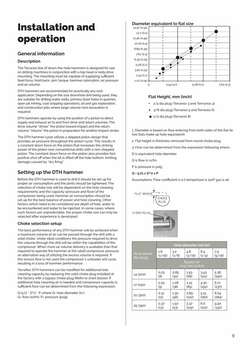
Diameter equivalent to flat size13�97 (0�55)
12�7 (0�5)
11�46 (0�45)
10�16 (0�4)
8�89 (0�35)
7�62 (0�3)
6�35 (0�25)
5�08 (0�2)
3�81 (0�15)
2�54 (0�1)
1�27 (0�05)0 2�54 (0�1) 5�08 (0�2) 7�62 (0�3)
Flat Height, mm (inch)
• 1/4 dia plug (Terranox 3 and Terrranox 4)
• 3/8 dia plug (Terranox 5 and Terranox 6)
• 1/2 dia plug (Terranox 8)
1. Diameter is based on flow entering from both sides of the flat (ie. two flats make up hole equivalent).
2� Flat height is thickness removed from round choke plug�
3� Flow can be determined from the expression following where:
D is equivalent hole diameter
Q is flow in scfm
P is pressure in psig
Q = 9�71 x D^2 x P
Assumptions: Flow coefficient is 0.7 temperture is 120F gas is air.
Air pressure Bar (psig)
Hole diameter mm (in)
1�6 (1/16)
3�2 (1/8)
4�8 (3/16)
6�4 (1/4)
7�9 (5/16)
Bypass air (m3/min (scfm)
14 (200)0�23 (8)
0�85 (30)
1�93 (68)
3�43 (121)
5�38 (190)
17 (250)0�25 (9)
1�08 (38)
2�41 (85)
4�30 (152)
6�71 (237)
21 (300)0�31 (11)
1�30 (46)
2�89 (102)
5�15 (182)
8�04 (284)
25 (350)0�37 (13)
1�50 (53)
3�37 (119)
6�0 (212)
9�40 (332)

10
Bailing velocity requirements
The need for adequate hole cleaning cannot be over emphasized� A hole that is not cleaned properly can result in poor performance, rapid wear of bits and accessories and in some cases loss of the drill and pipe down the hole� Hole cleaning is usually directly related to what is called bailing velocity or the speed of the air which is lifting cuttings from the hole�
Bailing velocity is defined as the velocity of the air in the hole annulus at atmospheric pressure. In other words, the effect of bottom hole pressure is not taken into account when computing bailing velocity� For conventional hole cleaning (no soaps or foams) bailing velocity should exceed 15 m/s (3000 ft�/min�)�
However, if possible, bailing velocity should not exceed 35 m/s (7000 ft�/min�)�
Bailing velocity can be computed by dividing the air consumption of the DTH by the annulus area� The equation following may be used:
Velocity [m/min�] (ft�/min�) = Air consumption [m3/min�] (scfm) Annulus area [sq� m] (sq� ft�)where:
• Air consumption is the rated delivery of the compressor or the air consumption of the drill at maximum pressure, whichever is less�
• Annulus area is the area between the hole bore and the drill rod� It can be computed as follows:
• Annulus area
[sq� m] =�785 x (hole dia� [m]2 - rod dia� [m]2) sq� ft�) =�0055 x (hole dia� [inches]2 - rod dia� [inches]2)
Bit installation
Bit splines should be well lubricated with rock drill oil or thread grease before the chuck is installed over the splines� Additionally, the threads on the chuck should also be well coated with thread grease before threading the chuck into the DTH� Remember to install the bit retaining ring halves before threading the chuck into the DTH�
Used bit and chuck
Caution must be used when installing a new bit on a used chuck or vice-versa� Some applications, usually soft rock where there is excessive bit travel within the splines, can develop uneven wear on the bit and chuck splines� When a new bit is installed in a used chuck the mating surfaces are likely to be poor� Check the condition of the chuck or bit splines when using a new bit or chuck if your application is prone to this form of spline wear�
It is also suggested that the chuck be rotated relative to the bit splines from time to time to even out the gouging and grooving which takes place due to erosive wear� This practice will extend your chuck and casing life�
Makeup torque and backhead closure
DTH series drills use a ‘’solid clamping’’ arrangement for locking internal components whereby parts are held in place under very high load. This system is highly effective in preventing motion (and subsequent damage) of internal parts�
Rotary head torque is not sufficient to close the backhead on DTH Series hammers� Because of the high load used to clamp the parts in place a high level of torque is needed to close the backhead gap� A supplementary wrench is needed to properly tighten the joint� The hydraulic wrench and wraparound tong supplied on most drilling rigs is usually sufficient. It is extremely important that the backhead gap be closed in these drills�
The presence of a gap between the casing and the backhead while drilling will increase the chances for loosening the backhead in the hole and possibly losing the drill In addition to at least closing the backhead gap, it is also recommended that the backhead
and chuck be torqued to approximately 40 - 55 N-m per mm (750 - 1000 ft�-lb per inch) of hammer diameter� This makeup torque insures against loosening joints in the hole and also preloads the threads sufficiently. Makeup torque for each hammer is presented in the General specifications table.
Drill Lubrication
Lubrication guidelines and specifications
All DTH´s require oil lubrication to resist wear, galling and corrosion. Additionally, the film of oil coating all internal parts seals internal clearance paths to reduce power-robbing leakage across sealing clearances� As a general rule of thumb the oil required is proportional to the volume of air being used�
Oil also needs to be of sufficiently high quality. It is recommended that TerraRoc rock drill oils are used�
For dry drilling (less than 7�6 lpm (2 gpm) of water injection) it is generally recommended that oil be injected into the drill air stream at the rate of �16 l (1/3 pint) of oil per hour for every 2�8 m3/min� (100 scfm) of air� For example a 25�5 m3/min� (900 scfm) compressor delivering full flow to a DTH would require 25.5 ÷ 2.8 x .16 = 1.6 l per hour (900 ÷ 100 x 1/3 = 3 pints per hour). For wet drilling (more than 7�6 lpm (2 gpm) it is suggested that the lubrication rate be doubled to �32 l (2/3 pint) of oil per hour for every 2�8 m3/min� (100 scfm) of air�
The additional oil compensates for the wash-out caused by water and the oil losses� Additional lubrication is also required when drilling with soap or foam� See the ‘’Drilling With Foam’’ section for more details�
Oil Injection Rate Oil Injection Rate l/hr (pints/hr)
Air Flow m3/min (scfm)
Dry DrillingWet or Hydrocyclone
4�25 (150) 0�2 (0�5) 0�5 (1�0)
7�08 (250) 0�4 (0�8) 0�8 (1�7)
9�91 (350) 0�6 (1�2) 1�1 (2�3)
14�2 (500) 0�8 (1�7) 1�6 (3�3)
17 (600) 1�0 (2�0) 1�9 (4�0)
21�2 (750) 1�2 (2�5) 2�4 (5�0)
22�7 (800) 1�3 (2�7) 2�5 (5�3)
25�5 (900) 1�4 (3�0) 2�8 (6�0)
29�7 (1050) 1�7 (3�5) 3�3 (7�0)
35�4 (1250) 2�0 (4�2) 3�9 (8�3)
42�5 (1500) 2�4 (5�0) 4�7 (10�0)
56�6 (2000) 3�2 (6�7) 6�3 (13�3)
84�9 (3000) 4�7 (10�0) 9�5 (20�0)
Lubricators
There are two primary types of lubricators; a plunger oiler and a venturi oiler:
A plunger oiler normally operates from a timed plunger system which delivers a fixed ‘’slug’’ of oil into the line in timed intervals. These systems are beneficial in that the oil reservoir does not need to contain a high pressure� Plunger lubricators are also insensi-tive to oil viscosity and temperature� However, because of their complexity, the reliability of plunger lubricators is not as good as the venturi type� Also, because oil is delivered as ‘’slugs’’ it is not atomized and delivered to the drill internals as evenly as a venturi�

11
Venturi type lubricators (sometimes referred to as pig oilers) operate in a similar fashion to a gasoline carburetor� A necked down area in the venturi creates a pressure drop which draws oil into the air stream. The oil is atomized and mixed very efficiently with the air providing maximum coverage and cohesion to internal drill components� A needle valve is usually used to adjust the oil volume delivered� Disadvantages of the venturi oiler are that it requires a pressurized reservoir, which is generally small in volume� Also, the lubrication rate is dependent on oil viscosity which varies with temperature�
Lubrication check
When oil is injected into an air stream with dry piping or hoses it takes a considerable amount of time to coat the walls of the piping so that the oil is actually delivered to the DTH� Until these surfaces are coated with an oil film very little is actually delivered to the DTH. It´s important to insure that an oil film is established before starting the DTH� It´s recommended that the drill be allowed to blow until a visible film of oil is developed on the bit blow holes.
Oil Injection Ratel/hr (pints/hr)
Air Flow Dry Drilling Wet or Hydrocyclone m3/min (scfm) Drilling
4.25 (150) .2 (0.5) .5 (1.0)7.08 (250) .4 (0.8) .8 (1.7)9.91 (350) .6 (1.2) 1.1 (2.3)14.2 (500) .8 (1.7) 1.6 (3.3)17 (600) 1.0 (2.0) 1.9 (4.0)21.2 (750) 1.2 (2.5) 2.4 (5.0)22.7 (800) 1.3 (2.7) 2.5 (5.3)25.5 (900) 1.4 (3.0) 2.8 (6.0)29.7 (1050) 1.7 (3.5) 3.3 (7.0)35.4 (1250) 2.0 (4.2) 3.9 (8.3)42.5 (1500) 2.4 (5.0) 4.7 (10.0)56.6 (2000) 3.2 (6.7) 6.3 (13.3)84.9 (3000) 4.7 (10.0) 9.5 (20.0)
LubricatorsThere are two primary types of lubricators; a plunger oiler and a venturi oiler:
A plunger oiler normally operates from a timed plunger system which delivers a fixed ‘’slug’’ of oil into the line in timed intervals. These systems are beneficial in that the oil reservoir does not need to contain a high pressure. Plunger lubricators are also insensitive to oil viscosity and temperature. However, because of their complexity, the reliability of plunger lubricators is not as good as the venturi type. Also, because oil is delivered as ‘’slugs’’ it is not atomized and delivered to the drill internals as evenly as a venturi.
Venturi type lubricators (sometimes referred to as pig oilers) operate in a similar fashion to a gasoline carburetor. A necked down area in the venturi creates a pressure drop which draws oil into the air stream. The oil is atomized and mixed very efficiently with the air providing maximum coverage and cohesion to internal drill components. A needle valve is usually used to adjust the oil volume delivered. Disadvantages of the venturi oiler are that it requires a pressurized reservoir, which is generally small in volume. Also, the lubrication rate is dependent on oil viscosity which varies with temperature.
Lubrication checkWhen oil is injected into an air stream with dry piping or hoses it takes a considerable amount of time to coat the walls of the piping so that the oil is actually delivered to the DTH. Until these surfaces are coated with an oil film very little is actually delivered to the DTH. It´s important to insure that an oil film is established before starting the DTH. It´s recommended that the drill be allowed to blow until a visible film of oil is developed on the bit blow holes.
Placing a piece of cardboard or wood beneath the blow holes gives a good indication when oil is passing through the drill. The cardboard or wood will become wet with oil when an adequate film of oil has been developed. If a drill string has not been used for some time and the oil has dried out it is suggested that a cup of oil be poured into each rod to assist in developing an oil film. After drilling with high levels of water injection it is important to note that any oil film has probably been washed off. For operators that switch from wet to dry drilling (i.e. waterwell and quarry) its important to redevelop the oil film.
Water injectionWater injection can cause a DTH to either consume more air (hold a lower pressure) or less air (hold a higher pressure) depending on the volume of fluids injected. For example, if a DTH is lubricated with oil and water is then injected at a low rate (less than 3.8 lpm (1 gpm)), the oil film which is sealing the internal leak paths is washed out and air consumption will increase (pressure will fall).
Conversely, if water is injected at a high rate (more than 11.4 lpm (3 gpm)) the fluid level will be sufficient to seal the leak paths and restrict the flow of air through the DTH. In this case the air consumption will decrease (pressure will increase).
The use of water, while required in most cases, does reduce component life. The following lists some of the problems that water injection can cause:
n Poor quality water can either be corrosive or cancarry contamination into the drill. Premature wear orcorrosion related failures can result. All water injectedinto a DTH should be neutral in pH and free fromparticulate contamination.
nWater injection reduces drill performanceconsiderably. Water restricts the flow and resultantpressure in working chambers of the drill and reducesface cleaning which causes regrinding of cuttings.
nWater present at the impact face causes cavitationof the bit and piston and jetting or cutting of theexhaust tube. In both cases component life is reduced.
A DTH that has been operated with water injection and will be idle for more than a few days should be dried out and lubricated with oil. This can be accomplished by blowing lubricated air through the tool when drilling is finished.
14
Safety and operating instructions
Placing a piece of cardboard or wood beneath the blow holes gives a good indication when oil is passing through the drill� The cardboard or wood will become wet with oil when an adequate film of oil has been developed. If a drill string has not been used for some time and the oil has dried out it is suggested that a cup of oil be poured into each rod to assist in developing an oil film. After drilling with high levels of water injection it is important to note that any oil film has probably been washed off. For operators that switch from wet to dry drilling (i�e� waterwell and quarry) its important to redevelop the oil film.
Water injection
Water injection can cause a DTH to either consume more air (hold a lower pressure) or less air (hold a higher pressure) depending on the volume of fluids injected. For example, if a DTH is lubricated with oil and water is then injected at a low rate (less than 3�8 lpm (1 gpm)), the oil film which is sealing the internal leak paths is washed out and air consumption will increase (pressure will fall)�
Conversely, if water is injected at a high rate (more than 11�4 lpm (3 gpm)) the fluid level will be sufficient to seal the leak paths and restrict the flow of air through the DTH. In this case the air consumption will decrease (pressure will increase)�
The use of water, while required in most cases, does reduce component life� The following lists some of the problems that water injection can cause:
• Poor quality water can either be corrosive or can carry contamination into the drill� Premature wear or corrosion related failures can result� All water injected into a DTH should be neutral in pH and free from particulate contamination�
• Water injection reduces drill performance considerably� Water restricts the flow and resultant pressure in working chambers of the drill and reduces face cleaning which causes regrinding of cuttings�
• Water present at the impact face causes cavitation of the bit and piston and jetting or cutting of the exhaust tube� In both cases component life is reduced�
A DTH that has been operated with water injection and will be idle for more than a few days should be dried out and lubricated with oil� This can be accomplished by blowing lubricated air through the tool when drilling is finished.
Drill operation
Drilling with foam
In certain drilling situations, it may be advantageous to use foam to improve hole cleaning and control backpressure� Use of a heavy (shaving cream consistency) foam can suspend drilled cuttings and allow them to be removed from the bore hole at bailing velocities much lower than when depending on air flow alone. Foam can also entrain and suspend formation water in instances of high water inflows, reducing backpressure on the drill.
TerraRoc DTH´s are compatible with all commonly available foaming compounds� Modern drilling foams are non-corrosive, but their effects create an environment suited to rapid corrosion of drill parts� The use of foam with a DTH requires extra care to maximize drill performance and life�
• Foam, being basically soap, breaks down rock drill oil, which can cause lubrication problems in the drill� Increase oil injection rates when drilling with foam�
• As foam passes through the drill, bubbles are created and destroyed� This action polishes the steel parts, making them more susceptible to corrosion�
• When drilling activity stops, the oil film normally present has been removed� This leaves the internal parts of the hammer without corrosion protection�
When drilling with foam is completed, all foam residues must be removed from the inside of the drill, and the parts must be coated with oil� Failure to do so will result in rapid corrosion of the internal parts and rapid wear when drilling resumes� The following procedure is is recommended when drilling with foam is completed:
• With the drill in blow position, shut off foam delivery and blow air with a large quantity of water through the hammer for several minutes�
• Shut off the water and continue to blow lubricated air through the hammer until a good flow of oil is seen at the bit.
• For best results, clean the hammer at the end of each day� If the hammer is to remain unused for an extended period, it is recommended that the DTH be disassembled, cleaned, oiled and reassembled before storage�
Collaring
Collaring a drilled hole is a critical stage of the drilling process� In blast holes it can determine the quality of the top of the hole and the ability to load a charge� In foundation and well drilling it can determine the overall straightness of the completed hole� It is suggested that a drill be collared with low pressure and feed until the hole has stabilized� Just as a twist drill needs to be controlled carefully when drilling with an electric hand drill, a DTH needs to be started with care�
Rotation speed
Recomended rotation speed for each Terranox hammer is presented in the Operational specifications chart on page 27.
Rotation speed directly affects the amount of angular index the bit inserts go through from one impact to the next� The optimum amount of index is dependent on variables such as blow energy (pressure), rock hardness, bit diameter, etc� The ideal rotation speed produces the best overall balance of penetration rate, bit life and smoothness of operation� It generally occurs when cuttings are their largest�
Determining the optimum rotation speed needs to be

12
carried out in the actual application� A good rule-ofthumb is to divide 300 by the bit diameter in inches to determine RPM� This will get the rotation to an acceptable speed. However, a fine-tuned rotation speed also needs to be correlated with penetration rate� It has been found that a proper rotation speed usually results in a 9�5 mm - 19 mm (3/8 in�- 3/4 in�) advance of the bit per revolution of the DTH� This measurement can normally be taken by using chalk or soapstone to scribe a spiral on the drill pipe while the drill is operating� The distance between the spirals (thread pitch) can be measured to determine if rotation speed should be increased or decreased� If the pitch is less than 9�5 mm (3/8 in�) the drill RPM should be decreased, if it is more than 19 mm (3/4 in�) the drill RPM should be increased�
The picture following shows an example of the marks left on a drill pipe when using chalk to mark the advance of the drill�
Drill operation
Drilling with foamIn certain drilling situations, it may be advantageous to use foam to improve hole cleaning and control backpressure. Use of a heavy (shaving cream consistency) foam can suspend drilled cuttings and allow them to be removed from the bore hole at bailing velocities much lower than when depending on air flow alone. Foam can also entrain and suspend formation water in instances of high water inflows, reducing backpressure on the drill.
Epiroc DTH´s are compatible with all commonly available foaming compounds. Modern drilling foams are non-corrosive, but their effects create an environment suited to rapid corrosion of drill parts. The use of foam with a DTH requires extra care to maximize drill performance and life.
n Foam, being basically soap, breaks down rock drilloil, which can cause lubrication problems in the drill.Increase oil injection rates when drilling with foam.
n As foam passes through the drill, bubbles arecreated and destroyed. This action polishes the steelparts, making them more susceptible to corrosion.
nWhen drilling activity stops, the oil film normallypresent has been removed. This leaves the internalparts of the hammer without corrosion protection.
When drilling with foam is completed, all foam residues must be removed from the inside of the drill, and the parts must be coated with oil. Failure to do so will result in rapid corrosion of the internal parts and rapid wear when drilling resumes. The following procedure is recommended when drilling with foam is completed:
nWith the drill in blow position, shut off foam deliveryand blow air with a large quantity of water through thehammer for several minutes.
n Shut off the water and continue to blow lubricatedair through the hammer until a good flow of oil is seenat the bit.
n For best results, clean the hammer at the end ofeach day. If the hammer is to remain unused for anextended period, it is recommended that the DTH bedisassembled, cleaned, oiled and reassembled beforestorage.
Rotation speedRecomended rotation speed for each Terranox hammer is presented in the Operational specifications chart on page 35 .Rotation speed directly affects the amount of angular index the bit inserts go through from one impact to the next. The optimum amount of index is dependent on variables such as blow energy (pressure), rock hardness, bit diameter, etc. The ideal rotation speed produces the best overall balance of penetration rate, bit life and smoothness of operation. It generally occurs when cuttings are their largest.
Determining the optimum rotation speed needs to be carried out in the actual application. A good rule-of-thumb is to divide 300 by the bit diameter in inches to determine RPM. This will get the rotation to an acceptable speed. However, a fine-tuned rotation speed also needs to be correlated with penetration rate. It has been found that a proper rotation speed usually results in a 9.5 mm - 19 mm (3/8 in.- 3/4 in.) advance of the bit per revolution of the DTH. This measurement can normally be taken by using chalk or soapstone to scribe a spiral on the drill pipe while the drill is operating. The distance between the spirals (thread pitch) can be measured to determine if rotation speed should be increased or decreased. If the pitch is less than 9.5 mm (3/8 in.) the drill RPM should be decreased, if it is more than 19 mm (3/4 in.) the drill RPM should be increased.
The picture following shows an example of the marks left on a drill pipe when using chalk to mark the advance of the drill.
Adjust RPM to give9.5 to 19 mm.(3/8 to 3/4 in)
Another method for setting rotation speed involves observing the wear flat developed on the gage (outer) carbide. The wear flat on the should be directly on the top of the inserts. A flat which is on the leading edge of carbide (side facing the direction of rotation) indicates rotation speed is too slow. Conversely, rotating too fast will cause rapid wear of the bit and the wear flat will be on the trailing edge of the carbide.
View showing wear flat on leading edge - indicates rotation too slow. Note that carbide failure was caused by the leading edge wear flat.
15
Safety and operating instructions
CollaringCollaring a drilled hole is a critical stage of the drilling process. In blast holes it can determine the quality of the top of the hole and the ability to load a charge. In foundation and well drilling it can determine the overall straightness of the completed hole. It is suggested that a drill be collared with low pressure and feed until the hole has stabilized. Just as a twist drill needs to be controlled carefully when drilling with an electric hand drill, a DTH needs to be started with care.
Adjust RPM to give 9�5 to 19 mm� (3/8 to 3/4 in)
Another method for setting rotation speed involves observing the wear flat developed on the gage (outer) carbide. The wear flat on the should be directly on the top of the inserts. A flat which is on the leading edge of carbide (side facing the direction of rotation) indicates rotation speed is too slow� Conversely, rotating too fast will cause rapid wear of the bit and the wear flat will be on the trailing edge of the carbide�
Drill operation
Drilling with foamIn certain drilling situations, it may be advantageous to use foam to improve hole cleaning and control backpressure. Use of a heavy (shaving cream consistency) foam can suspend drilled cuttings and allow them to be removed from the bore hole at bailing velocities much lower than when depending on air flow alone. Foam can also entrain and suspend formation water in instances of high water inflows, reducing backpressure on the drill.
Epiroc DTH´s are compatible with all commonly available foaming compounds. Modern drilling foams are non-corrosive, but their effects create an environment suited to rapid corrosion of drill parts. The use of foam with a DTH requires extra care to maximize drill performance and life.
n Foam, being basically soap, breaks down rock drilloil, which can cause lubrication problems in the drill.Increase oil injection rates when drilling with foam.
n As foam passes through the drill, bubbles arecreated and destroyed. This action polishes the steelparts, making them more susceptible to corrosion.
nWhen drilling activity stops, the oil film normallypresent has been removed. This leaves the internalparts of the hammer without corrosion protection.
When drilling with foam is completed, all foam residues must be removed from the inside of the drill, and the parts must be coated with oil. Failure to do so will result in rapid corrosion of the internal parts and rapid wear when drilling resumes. The following procedure is recommended when drilling with foam is completed:
nWith the drill in blow position, shut off foam deliveryand blow air with a large quantity of water through thehammer for several minutes.
n Shut off the water and continue to blow lubricatedair through the hammer until a good flow of oil is seenat the bit.
n For best results, clean the hammer at the end ofeach day. If the hammer is to remain unused for anextended period, it is recommended that the DTH bedisassembled, cleaned, oiled and reassembled beforestorage.
Rotation speedRecomended rotation speed for each Terranox hammer is presented in the Operational specifications chart on page 35 .Rotation speed directly affects the amount of angular index the bit inserts go through from one impact to the next. The optimum amount of index is dependent on variables such as blow energy (pressure), rock hardness, bit diameter, etc. The ideal rotation speed produces the best overall balance of penetration rate, bit life and smoothness of operation. It generally occurs when cuttings are their largest.
Determining the optimum rotation speed needs to be carried out in the actual application. A good rule-of-thumb is to divide 300 by the bit diameter in inches to determine RPM. This will get the rotation to an acceptable speed. However, a fine-tuned rotation speed also needs to be correlated with penetration rate. It has been found that a proper rotation speed usually results in a 9.5 mm - 19 mm (3/8 in.- 3/4 in.) advance of the bit per revolution of the DTH. This measurement can normally be taken by using chalk or soapstone to scribe a spiral on the drill pipe while the drill is operating. The distance between the spirals (thread pitch) can be measured to determine if rotation speed should be increased or decreased. If the pitch is less than 9.5 mm (3/8 in.) the drill RPM should be decreased, if it is more than 19 mm (3/4 in.) the drill RPM should be increased.
The picture following shows an example of the marks left on a drill pipe when using chalk to mark the advance of the drill.
Adjust RPM to give9.5 to 19 mm.(3/8 to 3/4 in)
Another method for setting rotation speed involves observing the wear flat developed on the gage (outer) carbide. The wear flat on the should be directly on the top of the inserts. A flat which is on the leading edge of carbide (side facing the direction of rotation) indicates rotation speed is too slow. Conversely, rotating too fast will cause rapid wear of the bit and the wear flat will be on the trailing edge of the carbide.
View showing wear flat on leading edge - indicates rotation too slow. Note that carbide failure was caused by the leading edge wear flat.
15
Safety and operating instructions
CollaringCollaring a drilled hole is a critical stage of the drilling process. In blast holes it can determine the quality of the top of the hole and the ability to load a charge. In foundation and well drilling it can determine the overall straightness of the completed hole. It is suggested that a drill be collared with low pressure and feed until the hole has stabilized. Just as a twist drill needs to be controlled carefully when drilling with an electric hand drill, a DTH needs to be started with care. View showing wear flat on leading edge - indicates rotation too
slow� Note that carbide failure was caused by the leading edge wear flat.
Rotation Torque
As a general rule of thumb, you should apply roughly 27 newton/meter (500 foot/pounds) of torque for each inch of bit diameter�
Example: 6 inch diameter bit x 27 newton/meter (500 ft/pounds) = 162 newton/meter (3000 ft/pounds) of rotation torque
Feed force (hold down and hold back)
Recomended feed force for each Terranox hammer is presented in the Operational specifications chart on page 27.
The force required to feed a percussive tool properly is directly proportional to the level of output power�
As a rule of thumb, DTH´s need to be fed with a force of roughly 9 kg per mm (500 lb per inch) of hammer diameter when operating at maximum power�
In many cases operators will simply adjust the feed pressure until rotation pressure starts to pulse and then back off slightly until rotation pressure becomes smooth. When a hole is first started, if the weight of the starter rod or collars is not sufficient to feed the drill then pull down will be needed� As the hole is advanced and more weight is added to the drill string, the level of pull down will need to be decreased� Eventually, the weight of the string may
exceed the proper feed force and the feed system will need to be shifted to a pull-back mode�
When drilling through varying conditions such as hard and soft or voided material, every effort should be made to keep the drill fed properly� A loose running DTH can cause damage to the tool and bit in a short period of time� The feed system of a drilling rig should have a sufficiently fast response so the DTH can ‘’catch up’’ with the bit when a void or soft seam is encountered�
It´s equally important to avoid feeding too hard through voided and fractured material� The piston in a DTH operates within the casing with a clearance of about �076 mm (�003 in�) on each side� While the casing appears very strong and stiff, it does not take much sideways pressure to distort the casing enough to cause interference with the piston as it reciprocates� If the casing is overfed through voided ground it is likely that deflection of the casing will occur� Frictional cracks will develop on the surface of the piston if the piston rubs hard enough against the wall of the casing while being distorted� These small frictional cracks can eventually grow and break the piston�
Feed force should be reduced when drilling through voided, unconsolidated or fractured ground to avoid twisting or distorting the hammer casing�
Hole cleaning, flushing and dust suppression
As stated previously, the importance of good hole cleaning cannot be over emphasized. A hole which is not cleaned effectively will cause reduced production (penetration rate), decreased bit and accessory life and could ultimately increase the risk of losing the drill and string in the hole�
Dry drilling
The most effective means for hole cleaning is drilling dry. Cuttings are normally lifted and cleaned from the hole very efficiently. Imagine blowing or sweeping dust or dirt from a floor when the floor is dry and wet: which is more effective? The same principle holds true for cleaning cuttings from a hole�
Wet drilling
Water injection is required in many applications for dust suppression or hole cleaning� Water injection rates for dust suppression only are usually less than 3�785 lpm (1 gpm) and just sufficient to moisten fine dust. It is usually common to use minimal water injection for dust suppression in shallow blasthole applications where water intrusion into the hole is not a problem�
Larger volumes of water injection are usually required in water well and deep-hole applications where a number of factors come into play;
• Water intrusion into the hole can develop mud rings where dry cuttings meet a seam of water entering the hole� Mud rings develop where dry cuttings stick to the wall of the hole when they hit the moist area� Water injection is needed to keep the hole wet enough to prevent these mud rings from developing� Fluid injection rates can vary from 3,785 - 30,28 lpm (1 - 8 gpm) depending of the hole size, rate of penetration and the type of material being drilled�
• Some materials such as those which drill fast or contain clay can sometimes require very heavy levels of water injection� These applications are unique in that they can either be drilled totally dry or totally wet, not in between. Marginal fluid injection results in making a tacky mud which sticks to the drill rods and hole wall and hinders hole cleaning. The correct level of fluid injection thins the paste so it will be cleared from the hole�
Bit changing
Removing the drill bit
Bit removal can be one of the most dangerous and frustrating tasks associated with the drilling operation� However, with the proper tools and techniques it should require no more than a

13
few minutes and few expletives to remove a bit� The following lists pointers which will be beneficial in helping you remove a bit quickly, safely and with reduced risk to damaging DTH parts and components:
1� Use sharp tong jaws� Worn or rolled over tong jaws increase the jaw pressure and make the wrench more prone to damaging the hammer case�
Many TerraRoc hammer cases are case hardened which means sharp jaws are needed to grip through the hardened case�
2� Grip the casing in the proper location� Gripping over the threads can make thread loosening extremely difficult. Example; as the wrench tightens it exerts an inward force which can pinch the threads if they are under the wrench jaw� This only increases the torque needed to uncouple the thread� Also, do not grip the casing in an area where the bore is not supported by either the piston or bearing� Gripping over an unsupported area can distort the bore� The figure and table below shows the recommended locations for wrenches�
Many Epiroc hammer cases are case hardened which means sharp jaws are needed to grip through the hardened case.
2. Grip the casing in the proper location. Gripping over the threads can make thread loosening extremely difficult. Example; as the wrench tightens it exerts an inward force which can pinch the threads if they are under the wrench jaw. Thisonly increases the torque needed to uncouplethe thread. Also, do not grip the casing in an area where the bore is not supported by either the piston or bearing. Gripping over an unsupported areacan distort the bore. The figure and table below shows the recommended locations for wrenches.
TOP OF JAW
MINIMUMDISTANCE
MAXIMUMDISTANCE
BOTTOM OF JAW
Chain Wrench Positions Minimum distance from Maximum distance
from DTH model chuck to lower jaw chuck to upper jaw
Terranox 3 85 mm (3.3 in.) 312 mm (12.3 in.)Terranox 4 165 mm (6.5 in.) 355 mm (14 in.) Terranox 5 165 mm (6.5 in.) 432 mm (17 in.)Terranox 6 165 mm (6.5 in.) 432 mm (17 in.)Terranox 8 165 mm (6.5 in.) 432 mm (17 in.)
3. Insure the bit fits properly within the bit basket.An improper fit may result in the bit slipping from thebasket.
4. Never weld or hammer on the casing to loosen it.All casings are case hardened for extended servicelife. The hard casing surface can be cracked bywelding or impacting with a sledge hammer. If a chuckor backhead is difficult to loosen, repeatedly tappingthe casing at the thread location with a brass bar orhammer while torque is applied may help loosen thejoint.
WARNING
n Insure chain wrenches or tongs are ratedfor the torque applied. The flying parts of chainwrenches can cause injury or death when theybreak!
Warranty will be voided by:
nWelding on casing will destroy heat treatment ofcasing causing cracks.
n Heating casing with a torch will distort bore and ruinheat treatment.
n Gripping with wrench across threads can distortbore and start cracks.
n Hammering on casing can form cracks on outside ofcasing.
Use sharp tong jaws to avoid problems
Removing the bit with percussion onlyIf a chuck is difficult to loosen it´s sometimes helpful to use low-pressure percussion assisted with reverse rotation to free the thread. The following lists the process and cautionary notes:
CAUTION
n Wear eye protection as the hammer will becycling above ground.
n Insure that all drill string joints are tight. Watchother string joints to insure they do not loosen beforethe chuck. If they do loosen, stop the process
Process instructions1. Place a piece of relatively hard polyurethane orconveyor belting in the bit break-out basket to absorb shock.
2. Remove all drill pipe so only the DTH and requiredadapters are attached to the rotary head.
3. Bring the drill in contact with the bit basket with arelatively light feed.
4. Bring the hammer pressure up to roughly 10 bar(150 psig).
5. See if the joint has loosened on its own after about10 seconds of cycling.
6. If the joint has not loosened, ‘’Bump’’ the rotation inreverse at a slow speed while the drill cycles until thejoint has loosened.
7. Stop as soon as the chuck loosens, grease and airwill be noticed coming from the loosened joint.
17
Safety and operating instructions
Top of jaw
Bottom of jaw
Maximum distance
Minimum distance
Chain Wrench Positions
from DTH model
Min� distance from chuck to lower jaw
Max� distance chuck to upper jaw
Terranox 3 85 mm (3�3 in�) 312 mm (12�3 in�)
Terranox 4 165 mm (6�5 in�) 355 mm (14 in�)
Terranox 5 165 mm (6�5 in�) 432 mm (17 in�)
Terranox 6 165 mm (6�5 in�) 432 mm (17 in�)
Terranox 8 165 mm (6�5 in�) 432 mm (17 in�)
3. Insure the bit fits properly within the bit basket. An improper fit may result in the bit slipping from the basket�
4� Never weld or hammer on the casing to loosen it� All casings are case hardened for extended service life� The hard casing surface can be cracked by welding or impacting with a sledge hammer� If a chuck or backhead is difficult to loosen, repeatedly tapping the casing at the thread location with a brass bar or hammer while torque is applied may help loosen the joint�
• Insure chain wrenches or tongs are rated for the torque applied� The flying parts of chain wrenches can cause injury or death when they break!
WARNING
Warranty will be voided by: n Welding on casing will destroy heat treatment of casing causing cracks�
• Heating casing with a torch will distort bore and ruin heat treatment�
• Gripping with wrench across threads can distort bore and start cracks�
• Hammering on casing can form cracks on outside of casing� Use sharp tong jaws to avoid problems
Removing the bit with percussion only
If a chuck is difficult to loosen it´s sometimes helpful to use low-pressure percussion assisted with reverse rotation to free the thread� The following lists the process and cautionary notes:
• Wear eye protection as the hammer will be cycling above ground�
• Insure that all drill string joints are tight� Watch other string joints to insure they do not loosen before the chuck� If they do loosen, stop the process�
CAUTION
Process instructions
1� Place a piece of relatively hard polyurethane or conveyor belting in the bit break-out basket to absorb shock�
2� Remove all drill pipe so only the DTH and required adapters are attached to the rotary head�
3� Bring the drill in contact with the bit basket with a relatively light feed�
4� Bring the hammer pressure up to roughly 10 bar (150 psig)�
5� See if the joint has loosened on its own after about 10 seconds of cycling�
6� If the joint has not loosened, ‘’Bump’’ the rotation in reverse at a slow speed while the drill cycles until the joint has loosened�
7� Stop as soon as the chuck loosens, grease and air will be noticed coming from the loosened joint�

14
Maintenance and repairFollow instructionsAlong with correct operational technique; proper and timely service and repair of a DTH can extent component life and reduce operational expenses considerably� The sections following describe how to disassemble, inspect, repair and reassemble all DTH´s�
Depending on the degree to which you plan on servicing a DTH, a number of tools are required� The following lists the tools needed for a complete overhaul of all DTH´s� Obviously a stand is required for holding the DTH and it is presumed that backhead and chuck threads have been loosened� Complete overhaul includes measuring and inspecting all clearances at seal locations and other wear points�
Tools required for DTH service and repair
Tool Terranox 3 Terranox 4 Terranox 5 Terranox 6 Terranox 8
Outside Micrometer
3-4”, 2-3”, 1-2” 3-4”, 2-3”,
1-2”4-5”, 3-4”, 2-3”, 1-2”
5-6”, 4-5”, 3-4”, 2-3”, 1-2”
7-8”, 5-6”, 4-5”, 7-8”, 2-3”
Feeler Gauges One set One set One set One set One set
Telescopic Bore gauges
Set up to 3” Set up to 3” Set up to 4” Set up to 5” Set up to 6”
Vernier Caliper 0-6” 0-6” 0-6” 0-6” 0-6”
Brass, or other soft metal, bar
3/4” dia� by 48” length
1” dia� by 48” length1-1/4” dia� by 48” length
1-3/4” dia� by 48” length
2” dia� by 48” length
”J” Wrench 2-1/2” 2-1/2” 3-1/2” 4” 6”
Breakout bench Product no� 90514057 Product code 9178
Applicable Applicable Applicable Applicable Applicable
Assembly toolsAn optional tool can be used to simplify the assembly of Terranox 3 and Terranox 6�
Terranox 3 assembly tool
Maintenance and repairFollow instructionsAlong with correct operational technique; proper and timely service and repair of a DTH can extent component life and reduce operational expenses considerably. The sections following describe how to disassemble, inspect, repair and reassemble all DTH´s.
Depending on the degree to which you plan on servicing a DTH, a number of tools are required. The following lists the tools needed for a complete overhaul of all DTH´s. Obviously a stand is required for holding the DTH and it is presumed that backhead and chuck threads have been loosened. Complete overhaul includes measuring and inspecting all clearances at seal locations and other wear points.
Tools required for DTH service and repair
Tool Terranox 3 Terranox 4 Terranox 5 Terrranox 6 Terranox 8
Outside Micrometer 3-4”, 2-3”, 3-4”, 2-3”, 4-5”, 3-4”, 5-6”, 4-5”, 7-8”, 5-6”,1-2” 1-2” 2-3”, 1-2” 3-4”, 2-3”, 4-5”, 7-8”,
1-2” 2-3”
Feeler Gauges One set One set One set One set One set
Telescopic Bore Set up to 3” Set up to 3” Set up to 4” Set up to 5” Set up to 6”Gauges
Vernier Caliper 0-6” 0-6” 0-6” 0-6” 0-6”
Brass, or other 3/4” dia. by 1” dia. by 1-1/4” dia. by 1-3/4” dia. by 2” dia. bysoft metal, bar 48” length 48” length 48” length 48” length 48” length
”J” Wrench 2-1/2” 2-1/2” 3-1/2” 4” 6”
Breakout bench Applicable Applicable Applicable Applicable Applicable Product no. 90514057 Product code 9178
A-A A
A
25.4
Ø 64- 00.
1+
Ø
67.8
- 00.5
+Ø
76.2
- 1.50
+Ø
19.7
44.5
69.9
3 x 45° 0.8 x 45°
R0.8
38.1Knurl this diameter mm (in.)
Assembly toolsAn optional tool can be used to simplify the assembly of Terranox 3 and Terranox 6
Terranox 3 assembly tool
18
Safety and operating instructions
6”

15
Terranox 6 assembly tool
DTH serviceIn most cases a DTH will only require servicing when the casing wears out or when performance deteriorates due to internal parts wear. The level of inspection can obviously be much less if the casing only needs replacement. If the DTH has lost performance a more detailed inspection will be required.
Terranox disassemblyThe following disassembly procedure starts with the presumption that the chuck and backhead threads have been loosened. While the disassembly process is similar for all DTH´s there are slight distinctions from one model to another that will be noted.
It´s important to note that the piston can only be removed from the chuck end of the drill .
1. Mark the casing so you can note which end is thebackhead side and which is the chuck end. Once thehammer has been disassembled it´s hard to tell whichend is which.
2. Loosen the chuck along with bit and retaining ringsand remove from casing.
3. Remove retaining rings and o-ring from bit shank.
4. Remove the chuck from the bit.
5. Remove the backhead from the other end of thecasing.
A-AA
A
29.7
33
57.2
112.
7- 00.
1+
Ø
118.
1- 00.
4+
Ø
127
Ø
0.8 x 45°
R1.5 (R MAX)
R1.5 (R MAX)
Knurl this diameter Break sharp edges .025
mm (in.)
Terranox 6 assembly tool
19
Safety and operating instructions
DTH serviceIn most cases a DTH will only require servicing when the casing wears out or when performance deteriorates due to internal parts wear� The level of inspection can obviously be much less if the casing only needs replacement� If the DTH has lost performance a more detailed inspection will be required�
Terranox disassemblyThe following disassembly procedure starts with the presumption that the chuck and backhead threads have been loosened� While the disassembly process is similar for all DTH´s there are slight distinctions from one model to another that will be noted�
It´s important to note that the piston can only be removed from the chuck end of the drill
1� Mark the casing so you can note which end is the backhead side and which is the chuck end� Once the hammer has been disassembled it´s hard to tell which end is which�
2� Loosen the chuck along with bit and retaining rings and remove from casing�
DTH serviceIn most cases a DTH will only require servicing when the casing wears out or when performance deteriorates due to internal parts wear. The level of inspection can obviously be much less if the casing only needs replacement. If the DTH has lost performance a more detailed inspection will be required.
Terranox disassemblyThe following disassembly procedure starts with the presumption that the chuck and backhead threads have been loosened. While the disassembly process is similar for all DTH´s there are slight distinctions from one model to another that will be noted.
It´s important to note that the piston can only be removed from the chuck end of the drill .
1. Mark the casing so you can note which end is thebackhead side and which is the chuck end. Once thehammer has been disassembled it´s hard to tell whichend is which.
2. Loosen the chuck along with bit and retaining ringsand remove from casing.
3. Remove retaining rings and o-ring from bit shank.
4. Remove the chuck from the bit.
5. Remove the backhead from the other end of thecasing.
A-AA
A
29.7
33
57.2
112.
7- 00.
1+
Ø
118.
1- 00.
4+
Ø
127
Ø
0.8 x 45°
R1.5 (R MAX)
R1.5 (R MAX)
Knurl this diameter Break sharp edges .025
mm (in.)
Terranox 6 assembly tool
19
Safety and operating instructions
3� Remove retaining rings and o-ring from bit shank�DTH serviceIn most cases a DTH will only require servicing when the casing wears out or when performance deteriorates due to internal parts wear. The level of inspection can obviously be much less if the casing only needs replacement. If the DTH has lost performance a more detailed inspection will be required.
Terranox disassemblyThe following disassembly procedure starts with the presumption that the chuck and backhead threads have been loosened. While the disassembly process is similar for all DTH´s there are slight distinctions from one model to another that will be noted.
It´s important to note that the piston can only be removed from the chuck end of the drill .
1. Mark the casing so you can note which end is thebackhead side and which is the chuck end. Once thehammer has been disassembled it´s hard to tell whichend is which.
2. Loosen the chuck along with bit and retaining ringsand remove from casing.
3. Remove retaining rings and o-ring from bit shank.
4. Remove the chuck from the bit.
5. Remove the backhead from the other end of thecasing.
A-AA
A
29.7
33
57.211
2.7
- 00.1
+Ø
118.
1- 00.
4+
Ø
127
Ø
0.8 x 45°
R1.5 (R MAX)
R1.5 (R MAX)
Knurl this diameter Break sharp edges .025
mm (in.)
Terranox 6 assembly tool
19
Safety and operating instructions
4� Remove the chuck from the bit�
DTH serviceIn most cases a DTH will only require servicing when the casing wears out or when performance deteriorates due to internal parts wear. The level of inspection can obviously be much less if the casing only needs replacement. If the DTH has lost performance a more detailed inspection will be required.
Terranox disassemblyThe following disassembly procedure starts with the presumption that the chuck and backhead threads have been loosened. While the disassembly process is similar for all DTH´s there are slight distinctions from one model to another that will be noted.
It´s important to note that the piston can only be removed from the chuck end of the drill .
1. Mark the casing so you can note which end is thebackhead side and which is the chuck end. Once thehammer has been disassembled it´s hard to tell whichend is which.
2. Loosen the chuck along with bit and retaining ringsand remove from casing.
3. Remove retaining rings and o-ring from bit shank.
4. Remove the chuck from the bit.
5. Remove the backhead from the other end of thecasing.
A-AA
A
29.7
33
57.2
112.
7- 00.
1+
Ø
118.
1- 00.
4+
Ø
127
Ø
0.8 x 45°
R1.5 (R MAX)
R1.5 (R MAX)
Knurl this diameter Break sharp edges .025
mm (in.)
Terranox 6 assembly tool
19
Safety and operating instructions

16
5� Remove the backhead from the other end of the casing�
Backhead
6. Remove the check valve, and check valve spring.
7. Remove the check valve and check valve springfrom the top of the air distributor. It is not necessaryto remove the choke plug unless it is damaged or abypass plug is required.
8. Remove the bit bearing (if your Terranox model isfurnished with one) from the hammer. The bearing cansometimes be removed by hand, but often will requirethe use of a bearing puller. When using a bearingpuller, be sure it is in contact with the bearing and notthe bearing retainer.
For Terranox 6: The bit bearing is held in place with a C-shaped retainer ring. Use heavy duty retainer ring pliers to remove the retainer ring. Remove the belleville springs and wear spacer (if used). The bearing can now be removed as described above.
9. Insert a brass rod through the piston bore until itmakes contact with the air distributor. Push the airdistributor and cylinder out of the casing.
To remove the air distributor and cylinder from Terronox 3 and Terranox 6 models push the piston toward the cylinder until it makes contact, then strike the piston struck end with a brass bar to unseat the cylinder retaining ring. The assembly can then be pushed out ot the casing
10. The cylinders for Terranox 8 are held inplace by acylinder stop ring located in a groove near the centerof the casing. These rings can be removed by hand.The cylinder must first be removed from the backheadend of the casing and the piston must be removedfrom the chuck end of the casing before the cylinderstop ring can be removed.
11. Insert the brass rod in the opposite side of thecasing and push the piston down until it contacts thepiston retainer ring. Strike the piston with the brassrod to unseat the ring and remove it from the casing.These can be removed by hand. It may be helpful touse a flat-bladed screwdriver to move the ring from itsgroove.
20
Safety and operating instructions
Backhead
6� Remove the check valve, and check valve spring�
Backhead
6. Remove the check valve, and check valve spring.
7. Remove the check valve and check valve springfrom the top of the air distributor. It is not necessaryto remove the choke plug unless it is damaged or abypass plug is required.
8. Remove the bit bearing (if your Terranox model isfurnished with one) from the hammer. The bearing cansometimes be removed by hand, but often will requirethe use of a bearing puller. When using a bearingpuller, be sure it is in contact with the bearing and notthe bearing retainer.
For Terranox 6: The bit bearing is held in place with a C-shaped retainer ring. Use heavy duty retainer ring pliers to remove the retainer ring. Remove the belleville springs and wear spacer (if used). The bearing can now be removed as described above.
9. Insert a brass rod through the piston bore until itmakes contact with the air distributor. Push the airdistributor and cylinder out of the casing.
To remove the air distributor and cylinder from Terronox 3 and Terranox 6 models push the piston toward the cylinder until it makes contact, then strike the piston struck end with a brass bar to unseat the cylinder retaining ring. The assembly can then be pushed out ot the casing
10. The cylinders for Terranox 8 are held inplace by acylinder stop ring located in a groove near the centerof the casing. These rings can be removed by hand.The cylinder must first be removed from the backheadend of the casing and the piston must be removedfrom the chuck end of the casing before the cylinderstop ring can be removed.
11. Insert the brass rod in the opposite side of thecasing and push the piston down until it contacts thepiston retainer ring. Strike the piston with the brassrod to unseat the ring and remove it from the casing.These can be removed by hand. It may be helpful touse a flat-bladed screwdriver to move the ring from itsgroove.
20
Safety and operating instructions
7� Remove the check valve and check valve spring from the top of the air distributor� It is not necessary to remove the choke plug unless it is damaged or a bypass plug is required�
Backhead
6. Remove the check valve, and check valve spring.
7. Remove the check valve and check valve springfrom the top of the air distributor. It is not necessaryto remove the choke plug unless it is damaged or abypass plug is required.
8. Remove the bit bearing (if your Terranox model isfurnished with one) from the hammer. The bearing cansometimes be removed by hand, but often will requirethe use of a bearing puller. When using a bearingpuller, be sure it is in contact with the bearing and notthe bearing retainer.
For Terranox 6: The bit bearing is held in place with a C-shaped retainer ring. Use heavy duty retainer ring pliers to remove the retainer ring. Remove the belleville springs and wear spacer (if used). The bearing can now be removed as described above.
9. Insert a brass rod through the piston bore until itmakes contact with the air distributor. Push the airdistributor and cylinder out of the casing.
To remove the air distributor and cylinder from Terronox 3 and Terranox 6 models push the piston toward the cylinder until it makes contact, then strike the piston struck end with a brass bar to unseat the cylinder retaining ring. The assembly can then be pushed out ot the casing
10. The cylinders for Terranox 8 are held inplace by acylinder stop ring located in a groove near the centerof the casing. These rings can be removed by hand.The cylinder must first be removed from the backheadend of the casing and the piston must be removedfrom the chuck end of the casing before the cylinderstop ring can be removed.
11. Insert the brass rod in the opposite side of thecasing and push the piston down until it contacts thepiston retainer ring. Strike the piston with the brassrod to unseat the ring and remove it from the casing.These can be removed by hand. It may be helpful touse a flat-bladed screwdriver to move the ring from itsgroove.
20
Safety and operating instructions
8� Remove the bit bearing (if your Terranox model is furnished with one) from the hammer� The bearing can sometimes be removed by hand, but often will require the use of a bearing puller� When using a bearing puller, be sure it is in contact with the bearing and not the bearing retainer�
For Terranox 6: The bit bearing is held in place with a C-shaped retainer ring� Use heavy duty retainer ring pliers to remove the retainer ring� Remove the belleville springs and wear spacer (if used)� The bearing can now be removed as described above�
Backhead
6. Remove the check valve, and check valve spring.
7. Remove the check valve and check valve springfrom the top of the air distributor. It is not necessaryto remove the choke plug unless it is damaged or abypass plug is required.
8. Remove the bit bearing (if your Terranox model isfurnished with one) from the hammer. The bearing cansometimes be removed by hand, but often will requirethe use of a bearing puller. When using a bearingpuller, be sure it is in contact with the bearing and notthe bearing retainer.
For Terranox 6: The bit bearing is held in place with a C-shaped retainer ring. Use heavy duty retainer ring pliers to remove the retainer ring. Remove the belleville springs and wear spacer (if used). The bearing can now be removed as described above.
9. Insert a brass rod through the piston bore until itmakes contact with the air distributor. Push the airdistributor and cylinder out of the casing.
To remove the air distributor and cylinder from Terronox 3 and Terranox 6 models push the piston toward the cylinder until it makes contact, then strike the piston struck end with a brass bar to unseat the cylinder retaining ring. The assembly can then be pushed out ot the casing
10. The cylinders for Terranox 8 are held inplace by acylinder stop ring located in a groove near the centerof the casing. These rings can be removed by hand.The cylinder must first be removed from the backheadend of the casing and the piston must be removedfrom the chuck end of the casing before the cylinderstop ring can be removed.
11. Insert the brass rod in the opposite side of thecasing and push the piston down until it contacts thepiston retainer ring. Strike the piston with the brassrod to unseat the ring and remove it from the casing.These can be removed by hand. It may be helpful touse a flat-bladed screwdriver to move the ring from itsgroove.
20
Safety and operating instructions
9� Insert a brass rod through the piston bore until it makes contact with the air distributor� Push the air distributor and cylinder out of the casing�
To remove the air distributor and cylinder from Terronox 3 and Terranox 6 models push the piston toward the cylinder until it makes contact, then strike the piston struck end with a brass bar to unseat the cylinder retaining ring� The assembly can then be pushed out ot the casing�
Backhead
6. Remove the check valve, and check valve spring.
7. Remove the check valve and check valve springfrom the top of the air distributor. It is not necessaryto remove the choke plug unless it is damaged or abypass plug is required.
8. Remove the bit bearing (if your Terranox model isfurnished with one) from the hammer. The bearing cansometimes be removed by hand, but often will requirethe use of a bearing puller. When using a bearingpuller, be sure it is in contact with the bearing and notthe bearing retainer.
For Terranox 6: The bit bearing is held in place with a C-shaped retainer ring. Use heavy duty retainer ring pliers to remove the retainer ring. Remove the belleville springs and wear spacer (if used). The bearing can now be removed as described above.
9. Insert a brass rod through the piston bore until itmakes contact with the air distributor. Push the airdistributor and cylinder out of the casing.
To remove the air distributor and cylinder from Terronox 3 and Terranox 6 models push the piston toward the cylinder until it makes contact, then strike the piston struck end with a brass bar to unseat the cylinder retaining ring. The assembly can then be pushed out ot the casing
10. The cylinders for Terranox 8 are held inplace by acylinder stop ring located in a groove near the centerof the casing. These rings can be removed by hand.The cylinder must first be removed from the backheadend of the casing and the piston must be removedfrom the chuck end of the casing before the cylinderstop ring can be removed.
11. Insert the brass rod in the opposite side of thecasing and push the piston down until it contacts thepiston retainer ring. Strike the piston with the brassrod to unseat the ring and remove it from the casing.These can be removed by hand. It may be helpful touse a flat-bladed screwdriver to move the ring from itsgroove.
20
Safety and operating instructions
10� The cylinders for Terranox 8 are held inplace by a cylinder stop ring located in a groove near the center of the casing� These rings can be removed by hand. The cylinder must first be removed from the backhead end of the casing and the piston must be removed from the chuck end of the casing before the cylinder stop ring can be removed�
11� Insert the brass rod in the opposite side of the casing and push the piston down until it contacts the piston retainer ring� Strike the piston with the brass rod to unseat the ring and remove it from the casing� These can be removed by hand� It may be helpful to use a flat-bladed screwdriver to move the ring from its groove.
12. Remove the piston from the chuck end of thecasing.
Terranox inspection
1. Casing outside diameter should be measuredroughly 50 - 75 mm (2 - 3 in.) from the end of thechuck end. Refer to the casing reverse and discarddimensions to determine if the casing should bereplaced or reversed. If the casing is to be reversedrefer to instructions in the assembly procedures.
n It´s suggested that the chuck be replaced when thecasing is reversed.
2. The chuck should be inspected from a fewperspectives:
n The overall length of the chuck should be checkedagainst specification. A short chuck can cause cyclingproblems, difficulty handling water and a rough drilloperation.
n The chuck should be replaced if spline wear isheavy or uneven. The chuck should be replaced ifits minimum outside diameter is less than the casingdiscard point.
21
Safety and operating instructions
The following lists critical measurements which are required to determine what parts, if any, require replacement, repair or reversal. Refer to the specifications for finding the appropriate discard point clearances. Bear in mind that discard point clearances represent an increase in clearance of 50% over the maximum as-new clearance. In some applications this clearance increase may represent too much performance loss and in other applications the opposite may be true.
Note that deterioration in drill performance is caused by the increase in clearance between two parts. It is obviously more cost effective to replace the part which decreases clearance the most at the lowest cost. The specifactions chapter in the end of this manual tabulates all the ‘’minimum material condition’’ diameters as new from which the wear on each part can be judged. This data should be used to determine which part(s) should be replaced when the net clearance is beyond the discard point.
12� Remove the piston from the chuck end of the casing�
12. Remove the piston from the chuck end of thecasing.
Terranox inspection
1. Casing outside diameter should be measuredroughly 50 - 75 mm (2 - 3 in.) from the end of thechuck end. Refer to the casing reverse and discarddimensions to determine if the casing should bereplaced or reversed. If the casing is to be reversedrefer to instructions in the assembly procedures.
n It´s suggested that the chuck be replaced when thecasing is reversed.
2. The chuck should be inspected from a fewperspectives:
n The overall length of the chuck should be checkedagainst specification. A short chuck can cause cyclingproblems, difficulty handling water and a rough drilloperation.
n The chuck should be replaced if spline wear isheavy or uneven. The chuck should be replaced ifits minimum outside diameter is less than the casingdiscard point.
21
Safety and operating instructions
The following lists critical measurements which are required to determine what parts, if any, require replacement, repair or reversal. Refer to the specifications for finding the appropriate discard point clearances. Bear in mind that discard point clearances represent an increase in clearance of 50% over the maximum as-new clearance. In some applications this clearance increase may represent too much performance loss and in other applications the opposite may be true.
Note that deterioration in drill performance is caused by the increase in clearance between two parts. It is obviously more cost effective to replace the part which decreases clearance the most at the lowest cost. The specifactions chapter in the end of this manual tabulates all the ‘’minimum material condition’’ diameters as new from which the wear on each part can be judged. This data should be used to determine which part(s) should be replaced when the net clearance is beyond the discard point.
Terranox inspectionThe following lists critical measurements which are required to determine what parts, if any, require replacement, repair or reversal. Refer to the specifications for finding the appropriate discard point clearances� Bear in mind that discard point

17
clearances represent an increase in clearance of 50% over the maximum as-new clearance� In some applications this clearance increase may represent too much performance loss and in other applications the opposite may be true�
Note that deterioration in drill performance is caused by the increase in clearance between two parts� It is obviously more cost effective to replace the part which decreases clearance the most at the lowest cost� The specifactions chapter in the end of this manual tabulates all the ‘’minimum material condition’’ diameters as new from which the wear on each part can be judged� This data should be used to determine which part(s) should be replaced when the net clearance is beyond the discard point�
1� Casing outside diameter should be measured roughly 50 - 75 mm (2 - 3 in�) from the end of the chuck end� Refer to the casing reverse and discard dimensions to determine if the casing should be replaced or reversed� If the casing is to be reversed refer to instructions in the assembly procedures�
• It´s suggested that the chuck be replaced when the casing is reversed�
12. Remove the piston from the chuck end of thecasing.
Terranox inspection
1. Casing outside diameter should be measuredroughly 50 - 75 mm (2 - 3 in.) from the end of thechuck end. Refer to the casing reverse and discarddimensions to determine if the casing should bereplaced or reversed. If the casing is to be reversedrefer to instructions in the assembly procedures.
n It´s suggested that the chuck be replaced when thecasing is reversed.
2. The chuck should be inspected from a fewperspectives:
n The overall length of the chuck should be checkedagainst specification. A short chuck can cause cyclingproblems, difficulty handling water and a rough drilloperation.
n The chuck should be replaced if spline wear isheavy or uneven. The chuck should be replaced ifits minimum outside diameter is less than the casingdiscard point.
21
Safety and operating instructions
The following lists critical measurements which are required to determine what parts, if any, require replacement, repair or reversal. Refer to the specifications for finding the appropriate discard point clearances. Bear in mind that discard point clearances represent an increase in clearance of 50% over the maximum as-new clearance. In some applications this clearance increase may represent too much performance loss and in other applications the opposite may be true.
Note that deterioration in drill performance is caused by the increase in clearance between two parts. It is obviously more cost effective to replace the part which decreases clearance the most at the lowest cost. The specifactions chapter in the end of this manual tabulates all the ‘’minimum material condition’’ diameters as new from which the wear on each part can be judged. This data should be used to determine which part(s) should be replaced when the net clearance is beyond the discard point.
2� The chuck should be inspected from a few perspectives:
• The overall length of the chuck should be checked against specification. A short chuck can cause cycling problems, difficulty handling water and a rough drill operation�
• The chuck should be replaced if spline wear is heavy or uneven� The chuck should be replaced if its minimum outside diameter is less than the casing discard point�
12. Remove the piston from the chuck end of thecasing.
Terranox inspection
1. Casing outside diameter should be measuredroughly 50 - 75 mm (2 - 3 in.) from the end of thechuck end. Refer to the casing reverse and discarddimensions to determine if the casing should bereplaced or reversed. If the casing is to be reversedrefer to instructions in the assembly procedures.
n It´s suggested that the chuck be replaced when thecasing is reversed.
2. The chuck should be inspected from a fewperspectives:
n The overall length of the chuck should be checkedagainst specification. A short chuck can cause cyclingproblems, difficulty handling water and a rough drilloperation.
n The chuck should be replaced if spline wear isheavy or uneven. The chuck should be replaced ifits minimum outside diameter is less than the casingdiscard point.
21
Safety and operating instructions
The following lists critical measurements which are required to determine what parts, if any, require replacement, repair or reversal. Refer to the specifications for finding the appropriate discard point clearances. Bear in mind that discard point clearances represent an increase in clearance of 50% over the maximum as-new clearance. In some applications this clearance increase may represent too much performance loss and in other applications the opposite may be true.
Note that deterioration in drill performance is caused by the increase in clearance between two parts. It is obviously more cost effective to replace the part which decreases clearance the most at the lowest cost. The specifactions chapter in the end of this manual tabulates all the ‘’minimum material condition’’ diameters as new from which the wear on each part can be judged. This data should be used to determine which part(s) should be replaced when the net clearance is beyond the discard point.
3�The backhead should be inspected from a few perspectives:
• The condition of the connection thread should be checked� A backhead should be replaced if the threads are torn, galled or damaged� The condition of the connection shoulder should also be inspected for a depression which means the thread will not make-up properly�
4� The backhead o-ring or check seal should be replaced if damaged in any way�
3.The backhead should be inspected from a fewperspectives:
n The condition of the connection thread should bechecked. A backhead should be replaced if the threadsare torn, galled or damaged. The condition of theconnection shoulder should also be inspected for adepression which means the thread will not make-upproperly.
4. The backhead o-ring or check seal should bereplaced if damaged in any way.
Thread condition Shoulder condition
O-ring/check seal condition
5. Inspect the check valve and spring. Replace ifcracked, torn, or if the seal is brittle.
6. Inspect the air distributor guide and the airdistributors guide stem for wear, scoring, or galling.Replace if worn beyond tabulated limits. A wearpattern on one side of the guide can indicatemisalignment in the drill. If this condition is observed,check other parts carefully to identify the source of themisalignment.
7. Inspect the air distributor guide stem or separateguide stem (Terranox 3 and Terranox 4).
8. Inspect the bearing bore just above the internalflutes for wear using a telescopic bore gage and amicrometer. Replace the bearing if the net clearancewith a new bit has worn beyond the discard point.Replace the bearing o-ring if it has been worn ordamaged.
9. Inspect the piston for wear using micrometers inthe four locations noted below. The piston usuallywears more than its mating parts so it´s likely that itwill affect clearance the most. Record the dimensionsfor comparison to mating parts (cylinder, distributorand casing) to determine which part offers the mosteconomical replacement cost.
nMeasure the tail outside diameter in the location shown.
n Measure the tail bore and inspect for damage.
n Measure the large piston diameter in the locationshown. NOTE: This is the most critical wear pointon the drill, as it has the greatest influence onperformance.
22
Safety and operating instructions
Thread conditionShoulder condition
O-ring/check seal condition
5� Inspect the check valve and spring� Replace if cracked, torn, or if the seal is brittle�
3.The backhead should be inspected from a fewperspectives:
n The condition of the connection thread should bechecked. A backhead should be replaced if the threadsare torn, galled or damaged. The condition of theconnection shoulder should also be inspected for adepression which means the thread will not make-upproperly.
4. The backhead o-ring or check seal should bereplaced if damaged in any way.
Thread condition Shoulder condition
O-ring/check seal condition
5. Inspect the check valve and spring. Replace ifcracked, torn, or if the seal is brittle.
6. Inspect the air distributor guide and the airdistributors guide stem for wear, scoring, or galling.Replace if worn beyond tabulated limits. A wearpattern on one side of the guide can indicatemisalignment in the drill. If this condition is observed,check other parts carefully to identify the source of themisalignment.
7. Inspect the air distributor guide stem or separateguide stem (Terranox 3 and Terranox 4).
8. Inspect the bearing bore just above the internalflutes for wear using a telescopic bore gage and amicrometer. Replace the bearing if the net clearancewith a new bit has worn beyond the discard point.Replace the bearing o-ring if it has been worn ordamaged.
9. Inspect the piston for wear using micrometers inthe four locations noted below. The piston usuallywears more than its mating parts so it´s likely that itwill affect clearance the most. Record the dimensionsfor comparison to mating parts (cylinder, distributorand casing) to determine which part offers the mosteconomical replacement cost.
nMeasure the tail outside diameter in the location shown.
n Measure the tail bore and inspect for damage.
n Measure the large piston diameter in the locationshown. NOTE: This is the most critical wear pointon the drill, as it has the greatest influence onperformance.
22
Safety and operating instructions
6� Inspect the air distributor guide and the air distributors guide stem for wear, scoring, or galling� Replace if worn beyond tabulated limits� A wear pattern on one side of the guide can indicate misalignment in the drill� If this condition is observed, check other parts carefully to identify the source of the misalignment�
7� Inspect the air distributor guide stem or separate guide stem (Terranox 3 and Terranox 4)�
3.The backhead should be inspected from a fewperspectives:
n The condition of the connection thread should bechecked. A backhead should be replaced if the threadsare torn, galled or damaged. The condition of theconnection shoulder should also be inspected for adepression which means the thread will not make-upproperly.
4. The backhead o-ring or check seal should bereplaced if damaged in any way.
Thread condition Shoulder condition
O-ring/check seal condition
5. Inspect the check valve and spring. Replace ifcracked, torn, or if the seal is brittle.
6. Inspect the air distributor guide and the airdistributors guide stem for wear, scoring, or galling.Replace if worn beyond tabulated limits. A wearpattern on one side of the guide can indicatemisalignment in the drill. If this condition is observed,check other parts carefully to identify the source of themisalignment.
7. Inspect the air distributor guide stem or separateguide stem (Terranox 3 and Terranox 4).
8. Inspect the bearing bore just above the internalflutes for wear using a telescopic bore gage and amicrometer. Replace the bearing if the net clearancewith a new bit has worn beyond the discard point.Replace the bearing o-ring if it has been worn ordamaged.
9. Inspect the piston for wear using micrometers inthe four locations noted below. The piston usuallywears more than its mating parts so it´s likely that itwill affect clearance the most. Record the dimensionsfor comparison to mating parts (cylinder, distributorand casing) to determine which part offers the mosteconomical replacement cost.
nMeasure the tail outside diameter in the location shown.
n Measure the tail bore and inspect for damage.
n Measure the large piston diameter in the locationshown. NOTE: This is the most critical wear pointon the drill, as it has the greatest influence onperformance.
22
Safety and operating instructions
8. Inspect the bearing bore just above the internal flutes for wear using a telescopic bore gage and a micrometer� Replace the bearing if the net clearance with a new bit has worn beyond the discard point� Replace the bearing o-ring if it has been worn or damaged�
3.The backhead should be inspected from a fewperspectives:
n The condition of the connection thread should bechecked. A backhead should be replaced if the threadsare torn, galled or damaged. The condition of theconnection shoulder should also be inspected for adepression which means the thread will not make-upproperly.
4. The backhead o-ring or check seal should bereplaced if damaged in any way.
Thread condition Shoulder condition
O-ring/check seal condition
5. Inspect the check valve and spring. Replace ifcracked, torn, or if the seal is brittle.
6. Inspect the air distributor guide and the airdistributors guide stem for wear, scoring, or galling.Replace if worn beyond tabulated limits. A wearpattern on one side of the guide can indicatemisalignment in the drill. If this condition is observed,check other parts carefully to identify the source of themisalignment.
7. Inspect the air distributor guide stem or separateguide stem (Terranox 3 and Terranox 4).
8. Inspect the bearing bore just above the internalflutes for wear using a telescopic bore gage and amicrometer. Replace the bearing if the net clearancewith a new bit has worn beyond the discard point.Replace the bearing o-ring if it has been worn ordamaged.
9. Inspect the piston for wear using micrometers inthe four locations noted below. The piston usuallywears more than its mating parts so it´s likely that itwill affect clearance the most. Record the dimensionsfor comparison to mating parts (cylinder, distributorand casing) to determine which part offers the mosteconomical replacement cost.
nMeasure the tail outside diameter in the location shown.
n Measure the tail bore and inspect for damage.
n Measure the large piston diameter in the locationshown. NOTE: This is the most critical wear pointon the drill, as it has the greatest influence onperformance.
22
Safety and operating instructions

18
9� Inspect the piston for wear using micrometers in the four locations noted below� The piston usually wears more than its mating parts so it´s likely that it will affect clearance the most. Record the dimensions for comparison to mating parts (cylinder, distributor and casing) to determine which part offers the most economical replacement cost�
• Measure the tail outside diameter in the location shown�
3.The backhead should be inspected from a fewperspectives:
n The condition of the connection thread should bechecked. A backhead should be replaced if the threadsare torn, galled or damaged. The condition of theconnection shoulder should also be inspected for adepression which means the thread will not make-upproperly.
4. The backhead o-ring or check seal should bereplaced if damaged in any way.
Thread condition Shoulder condition
O-ring/check seal condition
5. Inspect the check valve and spring. Replace ifcracked, torn, or if the seal is brittle.
6. Inspect the air distributor guide and the airdistributors guide stem for wear, scoring, or galling.Replace if worn beyond tabulated limits. A wearpattern on one side of the guide can indicatemisalignment in the drill. If this condition is observed,check other parts carefully to identify the source of themisalignment.
7. Inspect the air distributor guide stem or separateguide stem (Terranox 3 and Terranox 4).
8. Inspect the bearing bore just above the internalflutes for wear using a telescopic bore gage and amicrometer. Replace the bearing if the net clearancewith a new bit has worn beyond the discard point.Replace the bearing o-ring if it has been worn ordamaged.
9. Inspect the piston for wear using micrometers inthe four locations noted below. The piston usuallywears more than its mating parts so it´s likely that itwill affect clearance the most. Record the dimensionsfor comparison to mating parts (cylinder, distributorand casing) to determine which part offers the mosteconomical replacement cost.
nMeasure the tail outside diameter in the location shown.
n Measure the tail bore and inspect for damage.
n Measure the large piston diameter in the locationshown. NOTE: This is the most critical wear pointon the drill, as it has the greatest influence onperformance.
22
Safety and operating instructions
• Measure the tail bore and inspect for damage�
3.The backhead should be inspected from a fewperspectives:
n The condition of the connection thread should bechecked. A backhead should be replaced if the threadsare torn, galled or damaged. The condition of theconnection shoulder should also be inspected for adepression which means the thread will not make-upproperly.
4. The backhead o-ring or check seal should bereplaced if damaged in any way.
Thread condition Shoulder condition
O-ring/check seal condition
5. Inspect the check valve and spring. Replace ifcracked, torn, or if the seal is brittle.
6. Inspect the air distributor guide and the airdistributors guide stem for wear, scoring, or galling.Replace if worn beyond tabulated limits. A wearpattern on one side of the guide can indicatemisalignment in the drill. If this condition is observed,check other parts carefully to identify the source of themisalignment.
7. Inspect the air distributor guide stem or separateguide stem (Terranox 3 and Terranox 4).
8. Inspect the bearing bore just above the internalflutes for wear using a telescopic bore gage and amicrometer. Replace the bearing if the net clearancewith a new bit has worn beyond the discard point.Replace the bearing o-ring if it has been worn ordamaged.
9. Inspect the piston for wear using micrometers inthe four locations noted below. The piston usuallywears more than its mating parts so it´s likely that itwill affect clearance the most. Record the dimensionsfor comparison to mating parts (cylinder, distributorand casing) to determine which part offers the mosteconomical replacement cost.
nMeasure the tail outside diameter in the location shown.
n Measure the tail bore and inspect for damage.
n Measure the large piston diameter in the locationshown. NOTE: This is the most critical wear pointon the drill, as it has the greatest influence onperformance.
22
Safety and operating instructions
• Measure the large piston diameter in the location shown� NOTE: This is the most critical wear point on the drill, as it has the greatest influence on performance.
10. Carefully remove any sharp edges, burrs or nickswhich have developed on the piston using a handgrinder. Do not overheat the piston...it will crack ifoverheated! If the piston face is heavily cavitated orpitted either use a ceramic facing tool to dress theface of the piston or use a well cooled grinder. Ineither case, a maximum of 1.52 mm (.060 in.) can beremoved from the piston face.
11. If the casing does not require replacement due tooutside diameter wear, measure the bore diameterusing a telescopic bore gage and micrometer asshown. Record the measurement for later reference.Polish any rough or galled spots in the casing borewith emery cloth. Larger areas of damage can besmoothed out using a hand grinder with flap wheel. Becareful not to remove too much material from the boreto avoid degradation of hammer performance.
MEASURE AT THIS LOCATION(1/2’’ past long undercut)
12. Inspect the cylinder for cracks or damage.Measure the diameter of the bore and record for laterreference. Scored or galled areas of the bore can bepolished with emery cloth.
13. Measure and record the following clearances fromthe dimesnions recorded.
n Bit to bit bearing. n Piston to casing.
n Piston to cylinder. n Piston to guide.
14. Determine which parts have suffered the mostwear. Replace the part(s) needed to bring theclearances back to specification. The Clearence charttogether with The Service Specifications chart, locatedin the end of this manual, may be useful for recordingand determining which clearances require service.
Terranox assemblyThe DTH assembly process is identical to the disassembly process yet in reverse. The following guidelines should be used:
n All parts should be clean and free of grit dirt andother foreign material.
n All nicks and burrs on parts should have beenremoved.
n All parts should be coated with rockdrill oil andpreferably the same type to be used on the drilling rig
n All damaged o-rings should have been replaced if.All seals should be oiled or greased to avoid cutting ortearing.
n If corrosion is common it may be useful to spraythe threads on the casing with a corrosion protector.Make sure the threads are clean and dry and sufficientdrying time is allowed.
1. Install the backhead o-ring.
2. Install the cylinder into the backhead end of thecasing.
For Terranox 3 and Terranox 6 models, compress the cylinder retainer in the deeper groove and push it into the casing. An optional installation tool may be helpful for this process. The assembly tools are described in the begining of this chapter.
23
Safety and operating instructions
10� Carefully remove any sharp edges, burrs or nicks which have developed on the piston using a hand grinder� Do not overheat the piston���it will crack if overheated! If the piston face is heavily cavitated or pitted either use a ceramic facing tool to dress the face of the piston or use a well cooled grinder� In either case, a maximum of 1�52 mm (�060 in�) can be removed from the piston face�
11� If the casing does not require replacement due to outside diameter wear, measure the bore diameter using a telescopic bore gage and micrometer as shown� Record the measurement for later reference� Polish any rough or galled spots in the casing bore with emery cloth� Larger areas of damage can be smoothed out using a hand grinder with flap wheel. Be careful not to remove too much material from the bore to avoid degradation of hammer performance�
10. Carefully remove any sharp edges, burrs or nickswhich have developed on the piston using a handgrinder. Do not overheat the piston...it will crack ifoverheated! If the piston face is heavily cavitated orpitted either use a ceramic facing tool to dress theface of the piston or use a well cooled grinder. Ineither case, a maximum of 1.52 mm (.060 in.) can beremoved from the piston face.
11. If the casing does not require replacement due tooutside diameter wear, measure the bore diameterusing a telescopic bore gage and micrometer asshown. Record the measurement for later reference.Polish any rough or galled spots in the casing borewith emery cloth. Larger areas of damage can besmoothed out using a hand grinder with flap wheel. Becareful not to remove too much material from the boreto avoid degradation of hammer performance.
MEASURE AT THIS LOCATION(1/2’’ past long undercut)
12. Inspect the cylinder for cracks or damage.Measure the diameter of the bore and record for laterreference. Scored or galled areas of the bore can bepolished with emery cloth.
13. Measure and record the following clearances fromthe dimesnions recorded.
n Bit to bit bearing. n Piston to casing.
n Piston to cylinder. n Piston to guide.
14. Determine which parts have suffered the mostwear. Replace the part(s) needed to bring theclearances back to specification. The Clearence charttogether with The Service Specifications chart, locatedin the end of this manual, may be useful for recordingand determining which clearances require service.
Terranox assemblyThe DTH assembly process is identical to the disassembly process yet in reverse. The following guidelines should be used:
n All parts should be clean and free of grit dirt andother foreign material.
n All nicks and burrs on parts should have beenremoved.
n All parts should be coated with rockdrill oil andpreferably the same type to be used on the drilling rig
n All damaged o-rings should have been replaced if.All seals should be oiled or greased to avoid cutting ortearing.
n If corrosion is common it may be useful to spraythe threads on the casing with a corrosion protector.Make sure the threads are clean and dry and sufficientdrying time is allowed.
1. Install the backhead o-ring.
2. Install the cylinder into the backhead end of thecasing.
For Terranox 3 and Terranox 6 models, compress the cylinder retainer in the deeper groove and push it into the casing. An optional installation tool may be helpful for this process. The assembly tools are described in the begining of this chapter.
23
Safety and operating instructions
MEASURE AT THIS LOCATION (1/2’’ past long undercut)
12� Inspect the cylinder for cracks or damage� Measure the diameter of the bore and record for later reference� Scored or galled areas of the bore can be polished with emery cloth�
10. Carefully remove any sharp edges, burrs or nickswhich have developed on the piston using a handgrinder. Do not overheat the piston...it will crack ifoverheated! If the piston face is heavily cavitated orpitted either use a ceramic facing tool to dress theface of the piston or use a well cooled grinder. Ineither case, a maximum of 1.52 mm (.060 in.) can beremoved from the piston face.
11. If the casing does not require replacement due tooutside diameter wear, measure the bore diameterusing a telescopic bore gage and micrometer asshown. Record the measurement for later reference.Polish any rough or galled spots in the casing borewith emery cloth. Larger areas of damage can besmoothed out using a hand grinder with flap wheel. Becareful not to remove too much material from the boreto avoid degradation of hammer performance.
MEASURE AT THIS LOCATION(1/2’’ past long undercut)
12. Inspect the cylinder for cracks or damage.Measure the diameter of the bore and record for laterreference. Scored or galled areas of the bore can bepolished with emery cloth.
13. Measure and record the following clearances fromthe dimesnions recorded.
n Bit to bit bearing. n Piston to casing.
n Piston to cylinder. n Piston to guide.
14. Determine which parts have suffered the mostwear. Replace the part(s) needed to bring theclearances back to specification. The Clearence charttogether with The Service Specifications chart, locatedin the end of this manual, may be useful for recordingand determining which clearances require service.
Terranox assemblyThe DTH assembly process is identical to the disassembly process yet in reverse. The following guidelines should be used:
n All parts should be clean and free of grit dirt andother foreign material.
n All nicks and burrs on parts should have beenremoved.
n All parts should be coated with rockdrill oil andpreferably the same type to be used on the drilling rig
n All damaged o-rings should have been replaced if.All seals should be oiled or greased to avoid cutting ortearing.
n If corrosion is common it may be useful to spraythe threads on the casing with a corrosion protector.Make sure the threads are clean and dry and sufficientdrying time is allowed.
1. Install the backhead o-ring.
2. Install the cylinder into the backhead end of thecasing.
For Terranox 3 and Terranox 6 models, compress the cylinder retainer in the deeper groove and push it into the casing. An optional installation tool may be helpful for this process. The assembly tools are described in the begining of this chapter.
23
Safety and operating instructions
13� Measure and record the following clearances from the dimesnions recorded�
• Bit to bit bearing� n Piston to casing�
• Piston to cylinder� n Piston to guide�
14. Determine which parts have suffered the most wear. Replace the part(s) needed to bring the clearances back to specification. The Clearence chart together with The Service Specifications chart, located in the end of this manual, may be useful for recording and determining which clearances require service�
Terranox assemblyThe DTH assembly process is identical to the disassembly process yet in reverse� The following guidelines should be used:
• All parts should be clean and free of grit dirt and other foreign material�
• All nicks and burrs on parts should have been removed�
• All parts should be coated with rockdrill oil and preferably the same type to be used on the drilling rig
• All damaged o-rings should have been replaced if� All seals should be oiled or greased to avoid cutting or tearing�
• If corrosion is common it may be useful to spray the threads on the casing with a corrosion protector� Make sure the threads are clean and dry and sufficient drying time is allowed.
1� Install the backhead o-ring�
10. Carefully remove any sharp edges, burrs or nickswhich have developed on the piston using a handgrinder. Do not overheat the piston...it will crack ifoverheated! If the piston face is heavily cavitated orpitted either use a ceramic facing tool to dress theface of the piston or use a well cooled grinder. Ineither case, a maximum of 1.52 mm (.060 in.) can beremoved from the piston face.
11. If the casing does not require replacement due tooutside diameter wear, measure the bore diameterusing a telescopic bore gage and micrometer asshown. Record the measurement for later reference.Polish any rough or galled spots in the casing borewith emery cloth. Larger areas of damage can besmoothed out using a hand grinder with flap wheel. Becareful not to remove too much material from the boreto avoid degradation of hammer performance.
MEASURE AT THIS LOCATION(1/2’’ past long undercut)
12. Inspect the cylinder for cracks or damage.Measure the diameter of the bore and record for laterreference. Scored or galled areas of the bore can bepolished with emery cloth.
13. Measure and record the following clearances fromthe dimesnions recorded.
n Bit to bit bearing. n Piston to casing.
n Piston to cylinder. n Piston to guide.
14. Determine which parts have suffered the mostwear. Replace the part(s) needed to bring theclearances back to specification. The Clearence charttogether with The Service Specifications chart, locatedin the end of this manual, may be useful for recordingand determining which clearances require service.
Terranox assemblyThe DTH assembly process is identical to the disassembly process yet in reverse. The following guidelines should be used:
n All parts should be clean and free of grit dirt andother foreign material.
n All nicks and burrs on parts should have beenremoved.
n All parts should be coated with rockdrill oil andpreferably the same type to be used on the drilling rig
n All damaged o-rings should have been replaced if.All seals should be oiled or greased to avoid cutting ortearing.
n If corrosion is common it may be useful to spraythe threads on the casing with a corrosion protector.Make sure the threads are clean and dry and sufficientdrying time is allowed.
1. Install the backhead o-ring.
2. Install the cylinder into the backhead end of thecasing.
For Terranox 3 and Terranox 6 models, compress the cylinder retainer in the deeper groove and push it into the casing. An optional installation tool may be helpful for this process. The assembly tools are described in the begining of this chapter.
23
Safety and operating instructions

19
2� Install the cylinder into the backhead end of the casing�
For Terranox 3 and Terranox 6 models, compress the cylinder retainer in the deeper groove and push it into the casing� An optional installation tool may be helpful for this process� The assembly tools are described in the begining of this chapter�
5. Arranging the belleville springs as shown, install thebelleville stack and wear spacer (if used) on the airdistributor.
6. Coat the backhead threads with thread lubricantand install in the casing. When made up hand tight,there will be a gap between the backhead andcasing shoulders. If there is no gap, install a wearspacer above the belleville springs. this gap must beclosed by torqueing the threaded joint before drillingcommences.
8. Install the piston (small end first) in the casing fromthe chuck end. Push the piston by hand well past thebearing retainer ring groove. If the piston does notslide freely in the bore under hand pressure, check fordirt, debris, or distorted parts that are interfering withpiston action.
Required gap size, the difference between minimum and maximum backhead standoff, for each hammer is presented in the Service specifications chart.
9. Install the piston retainer ring into the casing bystarting it sideways, turning it to its proper orientationnear the groove until it snaps into place. A brassrod will be needed to tap the ring into its place. Besure to wear safety glasses as oil and grease in thegroove may be expelled when the ring snaps in place.
Use the assembly tool to insert the cylinder retainer into the casing.
Tap the assembly tool, cylinder with a brass bar to bring it to its proper position.
3. Install the air distributor o-ring (if removed) andinstall the air distributor into the cylinder. Tap the airdistributor with a brass bar to seat it in place.
4. Install the check valve and spring insuring the valvecycles freely.
24
Safety and operating instructions
Use the assembly tool to insert the cylinder retainer into the casing�
5. Arranging the belleville springs as shown, install thebelleville stack and wear spacer (if used) on the airdistributor.
6. Coat the backhead threads with thread lubricantand install in the casing. When made up hand tight,there will be a gap between the backhead andcasing shoulders. If there is no gap, install a wearspacer above the belleville springs. this gap must beclosed by torqueing the threaded joint before drillingcommences.
8. Install the piston (small end first) in the casing fromthe chuck end. Push the piston by hand well past thebearing retainer ring groove. If the piston does notslide freely in the bore under hand pressure, check fordirt, debris, or distorted parts that are interfering withpiston action.
Required gap size, the difference between minimum and maximum backhead standoff, for each hammer is presented in the Service specifications chart.
9. Install the piston retainer ring into the casing bystarting it sideways, turning it to its proper orientationnear the groove until it snaps into place. A brassrod will be needed to tap the ring into its place. Besure to wear safety glasses as oil and grease in thegroove may be expelled when the ring snaps in place.
Use the assembly tool to insert the cylinder retainer into the casing.
Tap the assembly tool, cylinder with a brass bar to bring it to its proper position.
3. Install the air distributor o-ring (if removed) andinstall the air distributor into the cylinder. Tap the airdistributor with a brass bar to seat it in place.
4. Install the check valve and spring insuring the valvecycles freely.
24
Safety and operating instructions
Tap the assembly tool, cylinder with a brass bar to bring it to its proper position�
3� Install the air distributor o-ring (if removed) and install the air distributor into the cylinder� Tap the air distributor with a brass bar to seat it in place�
5. Arranging the belleville springs as shown, install thebelleville stack and wear spacer (if used) on the airdistributor.
6. Coat the backhead threads with thread lubricantand install in the casing. When made up hand tight,there will be a gap between the backhead andcasing shoulders. If there is no gap, install a wearspacer above the belleville springs. this gap must beclosed by torqueing the threaded joint before drillingcommences.
8. Install the piston (small end first) in the casing fromthe chuck end. Push the piston by hand well past thebearing retainer ring groove. If the piston does notslide freely in the bore under hand pressure, check fordirt, debris, or distorted parts that are interfering withpiston action.
Required gap size, the difference between minimum and maximum backhead standoff, for each hammer is presented in the Service specifications chart.
9. Install the piston retainer ring into the casing bystarting it sideways, turning it to its proper orientationnear the groove until it snaps into place. A brassrod will be needed to tap the ring into its place. Besure to wear safety glasses as oil and grease in thegroove may be expelled when the ring snaps in place.
Use the assembly tool to insert the cylinder retainer into the casing.
Tap the assembly tool, cylinder with a brass bar to bring it to its proper position.
3. Install the air distributor o-ring (if removed) andinstall the air distributor into the cylinder. Tap the airdistributor with a brass bar to seat it in place.
4. Install the check valve and spring insuring the valvecycles freely.
24
Safety and operating instructions
4� Install the check valve and spring insuring the valve cycles freely�
5. Arranging the belleville springs as shown, install thebelleville stack and wear spacer (if used) on the airdistributor.
6. Coat the backhead threads with thread lubricantand install in the casing. When made up hand tight,there will be a gap between the backhead andcasing shoulders. If there is no gap, install a wearspacer above the belleville springs. this gap must beclosed by torqueing the threaded joint before drillingcommences.
8. Install the piston (small end first) in the casing fromthe chuck end. Push the piston by hand well past thebearing retainer ring groove. If the piston does notslide freely in the bore under hand pressure, check fordirt, debris, or distorted parts that are interfering withpiston action.
Required gap size, the difference between minimum and maximum backhead standoff, for each hammer is presented in the Service specifications chart.
9. Install the piston retainer ring into the casing bystarting it sideways, turning it to its proper orientationnear the groove until it snaps into place. A brassrod will be needed to tap the ring into its place. Besure to wear safety glasses as oil and grease in thegroove may be expelled when the ring snaps in place.
Use the assembly tool to insert the cylinder retainer into the casing.
Tap the assembly tool, cylinder with a brass bar to bring it to its proper position.
3. Install the air distributor o-ring (if removed) andinstall the air distributor into the cylinder. Tap the airdistributor with a brass bar to seat it in place.
4. Install the check valve and spring insuring the valvecycles freely.
24
Safety and operating instructions
5� Arranging the belleville springs as shown, install the belleville stack and wear spacer (if used) on the air distributor�
5. Arranging the belleville springs as shown, install thebelleville stack and wear spacer (if used) on the airdistributor.
6. Coat the backhead threads with thread lubricantand install in the casing. When made up hand tight,there will be a gap between the backhead andcasing shoulders. If there is no gap, install a wearspacer above the belleville springs. this gap must beclosed by torqueing the threaded joint before drillingcommences.
8. Install the piston (small end first) in the casing fromthe chuck end. Push the piston by hand well past thebearing retainer ring groove. If the piston does notslide freely in the bore under hand pressure, check fordirt, debris, or distorted parts that are interfering withpiston action.
Required gap size, the difference between minimum and maximum backhead standoff, for each hammer is presented in the Service specifications chart.
9. Install the piston retainer ring into the casing bystarting it sideways, turning it to its proper orientationnear the groove until it snaps into place. A brassrod will be needed to tap the ring into its place. Besure to wear safety glasses as oil and grease in thegroove may be expelled when the ring snaps in place.
Use the assembly tool to insert the cylinder retainer into the casing.
Tap the assembly tool, cylinder with a brass bar to bring it to its proper position.
3. Install the air distributor o-ring (if removed) andinstall the air distributor into the cylinder. Tap the airdistributor with a brass bar to seat it in place.
4. Install the check valve and spring insuring the valvecycles freely.
24
Safety and operating instructions
6� Coat the backhead threads with thread lubricant and install in the casing� When made up hand tight, there will be a gap between the backhead and casing shoulders� If there is no gap, install a wear spacer above the belleville springs� this gap must be closed by torqueing the threaded joint before drilling commences�
5. Arranging the belleville springs as shown, install thebelleville stack and wear spacer (if used) on the airdistributor.
6. Coat the backhead threads with thread lubricantand install in the casing. When made up hand tight,there will be a gap between the backhead andcasing shoulders. If there is no gap, install a wearspacer above the belleville springs. this gap must beclosed by torqueing the threaded joint before drillingcommences.
8. Install the piston (small end first) in the casing fromthe chuck end. Push the piston by hand well past thebearing retainer ring groove. If the piston does notslide freely in the bore under hand pressure, check fordirt, debris, or distorted parts that are interfering withpiston action.
Required gap size, the difference between minimum and maximum backhead standoff, for each hammer is presented in the Service specifications chart.
9. Install the piston retainer ring into the casing bystarting it sideways, turning it to its proper orientationnear the groove until it snaps into place. A brassrod will be needed to tap the ring into its place. Besure to wear safety glasses as oil and grease in thegroove may be expelled when the ring snaps in place.
Use the assembly tool to insert the cylinder retainer into the casing.
Tap the assembly tool, cylinder with a brass bar to bring it to its proper position.
3. Install the air distributor o-ring (if removed) andinstall the air distributor into the cylinder. Tap the airdistributor with a brass bar to seat it in place.
4. Install the check valve and spring insuring the valvecycles freely.
24
Safety and operating instructions
8. Install the piston (small end first) in the casing from the chuck end� Push the piston by hand well past the bearing retainer ring groove� If the piston does not slide freely in the bore under hand pressure, check for dirt, debris, or distorted parts that are interfer-ing with piston action�
Required gap size, the difference between minimum and maximum backhead standoff, for each hammer is presented in the Service specifications chart.
5. Arranging the belleville springs as shown, install thebelleville stack and wear spacer (if used) on the airdistributor.
6. Coat the backhead threads with thread lubricantand install in the casing. When made up hand tight,there will be a gap between the backhead andcasing shoulders. If there is no gap, install a wearspacer above the belleville springs. this gap must beclosed by torqueing the threaded joint before drillingcommences.
8. Install the piston (small end first) in the casing fromthe chuck end. Push the piston by hand well past thebearing retainer ring groove. If the piston does notslide freely in the bore under hand pressure, check fordirt, debris, or distorted parts that are interfering withpiston action.
Required gap size, the difference between minimum and maximum backhead standoff, for each hammer is presented in the Service specifications chart.
9. Install the piston retainer ring into the casing bystarting it sideways, turning it to its proper orientationnear the groove until it snaps into place. A brassrod will be needed to tap the ring into its place. Besure to wear safety glasses as oil and grease in thegroove may be expelled when the ring snaps in place.
Use the assembly tool to insert the cylinder retainer into the casing.
Tap the assembly tool, cylinder with a brass bar to bring it to its proper position.
3. Install the air distributor o-ring (if removed) andinstall the air distributor into the cylinder. Tap the airdistributor with a brass bar to seat it in place.
4. Install the check valve and spring insuring the valvecycles freely.
24
Safety and operating instructions
9� Install the piston retainer ring into the casing by starting it sideways, turning it to its proper orientation near the groove until it snaps into place� A brass rod will be needed to tap the ring into its place� Be sure to wear safety glasses as oil and grease in the groove may be expelled when the ring snaps in place�

20
Terranox 8 use a polymer piston retaining ring� These are installed by hand� A screwdriver may be helpful to insure the ring is evenly seated in its groove�
Terranox 8 use a polymer piston retaining ring. These are installed by hand. A screwdriver may be helpful to insure the ring is evenly seated in its groove.
10. If your hammer is furnished with a bit bearinginsure the bit bearing o-ring is in good condition. Slidethe bearing (stepped end first) into the casing until itseats against the bearing retainer ring. The bearingmay require tapping with a brass rod to keep it frombinding in the casing bore. The piston may be used toseat the bearing by inserting it into the casing, largeend first, and tapping the bearing in place. Heavyimpact is not normally required. If the bearing is verytight, it may indicate damage to the bearing and/orcasing.
11. If your hammer is furnished with a bearing retainerand/or belleville springs on the chuck end, assemblethem as shown. A retaining ring pliers is required toinstall the retainer on the Teranox 6 model.
12. Coat the bit splines liberally with copper or zincbased thread compound and install the chuck on thebit.
25
Safety and operating instructionsTerranox 8 use a polymer piston retaining ring. These are installed by hand. A screwdriver may be helpful to insure the ring is evenly seated in its groove.
10. If your hammer is furnished with a bit bearinginsure the bit bearing o-ring is in good condition. Slidethe bearing (stepped end first) into the casing until itseats against the bearing retainer ring. The bearingmay require tapping with a brass rod to keep it frombinding in the casing bore. The piston may be used toseat the bearing by inserting it into the casing, largeend first, and tapping the bearing in place. Heavyimpact is not normally required. If the bearing is verytight, it may indicate damage to the bearing and/orcasing.
11. If your hammer is furnished with a bearing retainerand/or belleville springs on the chuck end, assemblethem as shown. A retaining ring pliers is required toinstall the retainer on the Teranox 6 model.
12. Coat the bit splines liberally with copper or zincbased thread compound and install the chuck on thebit.
25
Safety and operating instructions
10� If your hammer is furnished with a bit bearing insure the bit bearing o-ring is in good condition� Slide the bearing (stepped end first) into the casing until it seats against the bearing retainer ring. The bearing may require tapping with a brass rod to keep it from binding in the casing bore� The piston may be used to seat the bearing by inserting it into the casing, large end first, and tapping the bearing in place� Heavy impact is not normally required� If the bearing is very tight, it may indicate damage to the bearing and/or casing�
Terranox 8 use a polymer piston retaining ring. These are installed by hand. A screwdriver may be helpful to insure the ring is evenly seated in its groove.
10. If your hammer is furnished with a bit bearinginsure the bit bearing o-ring is in good condition. Slidethe bearing (stepped end first) into the casing until itseats against the bearing retainer ring. The bearingmay require tapping with a brass rod to keep it frombinding in the casing bore. The piston may be used toseat the bearing by inserting it into the casing, largeend first, and tapping the bearing in place. Heavyimpact is not normally required. If the bearing is verytight, it may indicate damage to the bearing and/orcasing.
11. If your hammer is furnished with a bearing retainerand/or belleville springs on the chuck end, assemblethem as shown. A retaining ring pliers is required toinstall the retainer on the Teranox 6 model.
12. Coat the bit splines liberally with copper or zincbased thread compound and install the chuck on thebit.
25
Safety and operating instructions
11� If your hammer is furnished with a bearing retainer and/or belleville springs on the chuck end, assemble them as shown� A retaining ring pliers is required to install the retainer on the Terranox 6 model�
Terranox 8 use a polymer piston retaining ring. These are installed by hand. A screwdriver may be helpful to insure the ring is evenly seated in its groove.
10. If your hammer is furnished with a bit bearinginsure the bit bearing o-ring is in good condition. Slidethe bearing (stepped end first) into the casing until itseats against the bearing retainer ring. The bearingmay require tapping with a brass rod to keep it frombinding in the casing bore. The piston may be used toseat the bearing by inserting it into the casing, largeend first, and tapping the bearing in place. Heavyimpact is not normally required. If the bearing is verytight, it may indicate damage to the bearing and/orcasing.
11. If your hammer is furnished with a bearing retainerand/or belleville springs on the chuck end, assemblethem as shown. A retaining ring pliers is required toinstall the retainer on the Teranox 6 model.
12. Coat the bit splines liberally with copper or zincbased thread compound and install the chuck on thebit.
25
Safety and operating instructions
Terranox 8 use a polymer piston retaining ring. These are installed by hand. A screwdriver may be helpful to insure the ring is evenly seated in its groove.
10. If your hammer is furnished with a bit bearinginsure the bit bearing o-ring is in good condition. Slidethe bearing (stepped end first) into the casing until itseats against the bearing retainer ring. The bearingmay require tapping with a brass rod to keep it frombinding in the casing bore. The piston may be used toseat the bearing by inserting it into the casing, largeend first, and tapping the bearing in place. Heavyimpact is not normally required. If the bearing is verytight, it may indicate damage to the bearing and/orcasing.
11. If your hammer is furnished with a bearing retainerand/or belleville springs on the chuck end, assemblethem as shown. A retaining ring pliers is required toinstall the retainer on the Teranox 6 model.
12. Coat the bit splines liberally with copper or zincbased thread compound and install the chuck on thebit.
25
Safety and operating instructionsTerranox 8 use a polymer piston retaining ring. These are installed by hand. A screwdriver may be helpful to insure the ring is evenly seated in its groove.
10. If your hammer is furnished with a bit bearinginsure the bit bearing o-ring is in good condition. Slidethe bearing (stepped end first) into the casing until itseats against the bearing retainer ring. The bearingmay require tapping with a brass rod to keep it frombinding in the casing bore. The piston may be used toseat the bearing by inserting it into the casing, largeend first, and tapping the bearing in place. Heavyimpact is not normally required. If the bearing is verytight, it may indicate damage to the bearing and/orcasing.
11. If your hammer is furnished with a bearing retainerand/or belleville springs on the chuck end, assemblethem as shown. A retaining ring pliers is required toinstall the retainer on the Teranox 6 model.
12. Coat the bit splines liberally with copper or zincbased thread compound and install the chuck on thebit.
25
Safety and operating instructions
12� Coat the bit splines liberally with copper or zinc based thread compound and install the chuck on the bit�
Terranox 8 use a polymer piston retaining ring. These are installed by hand. A screwdriver may be helpful to insure the ring is evenly seated in its groove.
10. If your hammer is furnished with a bit bearinginsure the bit bearing o-ring is in good condition. Slidethe bearing (stepped end first) into the casing until itseats against the bearing retainer ring. The bearingmay require tapping with a brass rod to keep it frombinding in the casing bore. The piston may be used toseat the bearing by inserting it into the casing, largeend first, and tapping the bearing in place. Heavyimpact is not normally required. If the bearing is verytight, it may indicate damage to the bearing and/orcasing.
11. If your hammer is furnished with a bearing retainerand/or belleville springs on the chuck end, assemblethem as shown. A retaining ring pliers is required toinstall the retainer on the Teranox 6 model.
12. Coat the bit splines liberally with copper or zincbased thread compound and install the chuck on thebit.
25
Safety and operating instructions
13� Install the bit retaining ring and o-ring onto the bit and chuck�13. Install the bit retaining ring and o-ring onto the bitand chuck.
14. Coat the chuck threads with copper or zinc basedthread compound and thread the bit, chuck, andretainer ring assembly into the casing. Be sure totorque the chuck to specifications before drilling.
Exhaust tube replacement and installationExhaust tubes (footvalves) can become damaged during handling or physically eroded while in service, the net result is that they need to be serviced from time to time.
Tube failures will generally occur due to erosion caused by the jetting of water, oil and grit which is displaced as the piston strikes the bit. This form of failure is common in waterwell applications where injection rates are high. This high velocity jet of material actually erodes away the base of the tube and can eventually cause the tube to fail. Tube erosion can be reduced by insuring water is clean and free from particulate matter and that excessive fluid injection is avoided. It´s a good idea to monitor tube erosion and make replacements as needed before a hole is started to avoid a costly trip out of the hole.
Exhaust tubes can be removed by cutting off the remaining portion of the tube and prying the remaining piece out with a screwdriver. It may be useful to use a small rotary file to relieve the bore of the tube which remains in the bit. However, be careful not to touch the bit tube bore with the rotary file or a heat check followed by bit failure may result. The tube can also be heated slightly to soften the plastic. Avoid breathing
fumes which may come from the heated plastic and also be careful not to overheat the bit.
A new exhaust tube can be installed by driving the tube into the bit with a rubber faced mallet or with a block of wood between the hammer and tube. Do not hit the tube directly with a metal hammer or the tube may be damaged. Alternatively, the tube can be pressed into the bore using a press or even the table and feed on a drilling rig. Be careful not to over-press the tube. Correct exhaust tube extension for each hammer is presented in the Service specifications chart.
Correct exhausttube extension
26
Safety and operating instructions

21
14� Coat the chuck threads with copper or zinc based thread compound and thread the bit, chuck, and retainer ring assembly into the casing. Be sure to torque the chuck to specifications before drilling�
13. Install the bit retaining ring and o-ring onto the bitand chuck.
14. Coat the chuck threads with copper or zinc basedthread compound and thread the bit, chuck, andretainer ring assembly into the casing. Be sure totorque the chuck to specifications before drilling.
Exhaust tube replacement and installationExhaust tubes (footvalves) can become damaged during handling or physically eroded while in service, the net result is that they need to be serviced from time to time.
Tube failures will generally occur due to erosion caused by the jetting of water, oil and grit which is displaced as the piston strikes the bit. This form of failure is common in waterwell applications where injection rates are high. This high velocity jet of material actually erodes away the base of the tube and can eventually cause the tube to fail. Tube erosion can be reduced by insuring water is clean and free from particulate matter and that excessive fluid injection is avoided. It´s a good idea to monitor tube erosion and make replacements as needed before a hole is started to avoid a costly trip out of the hole.
Exhaust tubes can be removed by cutting off the remaining portion of the tube and prying the remaining piece out with a screwdriver. It may be useful to use a small rotary file to relieve the bore of the tube which remains in the bit. However, be careful not to touch the bit tube bore with the rotary file or a heat check followed by bit failure may result. The tube can also be heated slightly to soften the plastic. Avoid breathing
fumes which may come from the heated plastic and also be careful not to overheat the bit.
A new exhaust tube can be installed by driving the tube into the bit with a rubber faced mallet or with a block of wood between the hammer and tube. Do not hit the tube directly with a metal hammer or the tube may be damaged. Alternatively, the tube can be pressed into the bore using a press or even the table and feed on a drilling rig. Be careful not to over-press the tube. Correct exhaust tube extension for each hammer is presented in the Service specifications chart.
Correct exhausttube extension
26
Safety and operating instructions
Exhaust tube replacement and installation
Exhaust tubes (footvalves) can become damaged during handling or physically eroded while in service, the net result is that they need to be serviced from time to time�
Tube failures will generally occur due to erosion caused by the jetting of water, oil and grit which is displaced as the piston strikes the bit� This form of failure is common in waterwell applications where injection rates are high� This high velocity jet of material actually erodes away the base of the tube and can eventually cause the tube to fail� Tube erosion can be reduced by insuring water is clean and free from particulate matter and that excessive fluid injection is avoided. It´s a good idea to monitor tube erosion and make replacements as needed before a hole is started to avoid a costly trip out of the hole�
Exhaust tubes can be removed by cutting off the remaining portion of the tube and prying the remaining piece out with a screwdriver� It may be useful to use a small rotary file to relieve the bore of the tube which remains in the bit� However, be careful not to touch the bit tube bore with the rotary file or a heat check followed by bit failure may result� The tube can also be heated slightly to soften the plastic� Avoid breathing fumes which may come from the heated plastic and also be careful not to overheat the bit�
A new exhaust tube can be installed by driving the tube into the bit with a rubber faced mallet or with a block of wood between the hammer and tube� Do not hit the tube directly with a metal hammer or the tube may be damaged� Alternatively, the tube can be pressed into the bore using a press or even the table and feed on a drilling rig� Be careful not to over-press the tube� Correct exhaust tube extension for each hammer is presented in the Service specifications chart.
13. Install the bit retaining ring and o-ring onto the bitand chuck.
14. Coat the chuck threads with copper or zinc basedthread compound and thread the bit, chuck, andretainer ring assembly into the casing. Be sure totorque the chuck to specifications before drilling.
Exhaust tube replacement and installationExhaust tubes (footvalves) can become damaged during handling or physically eroded while in service, the net result is that they need to be serviced from time to time.
Tube failures will generally occur due to erosion caused by the jetting of water, oil and grit which is displaced as the piston strikes the bit. This form of failure is common in waterwell applications where injection rates are high. This high velocity jet of material actually erodes away the base of the tube and can eventually cause the tube to fail. Tube erosion can be reduced by insuring water is clean and free from particulate matter and that excessive fluid injection is avoided. It´s a good idea to monitor tube erosion and make replacements as needed before a hole is started to avoid a costly trip out of the hole.
Exhaust tubes can be removed by cutting off the remaining portion of the tube and prying the remaining piece out with a screwdriver. It may be useful to use a small rotary file to relieve the bore of the tube which remains in the bit. However, be careful not to touch the bit tube bore with the rotary file or a heat check followed by bit failure may result. The tube can also be heated slightly to soften the plastic. Avoid breathing
fumes which may come from the heated plastic and also be careful not to overheat the bit.
A new exhaust tube can be installed by driving the tube into the bit with a rubber faced mallet or with a block of wood between the hammer and tube. Do not hit the tube directly with a metal hammer or the tube may be damaged. Alternatively, the tube can be pressed into the bore using a press or even the table and feed on a drilling rig. Be careful not to over-press the tube. Correct exhaust tube extension for each hammer is presented in the Service specifications chart.
Correct exhausttube extension
26
Safety and operating instructions
Correct exhaust tube extension
BitsSelecting the right bitTerraRoc has a comprehensive range of DTH drill bits to match all conceivable applications� Each bit is made from quality alloy steel, and has been precision machined to produce a perfect body, heat treated to the required hardness, given surface compression for fatigue resistance, and fitted with precision buttons manufactured in-house�
Five basic designs are available: Convex, Flat front, SpeedBit, Concave, and Rocket bit. These are designed for specific applications for all rock types, hardness’s and conditions�
Bit life and rate of penetration are the most important criteria in selecting the right bit for a particular application� In most cases, the focus is on productivity, so the fast cuttings removal features of the SpeedBit and Convex/Ballistic designs are preferable, to ensure the buttons are cutting clean, with the minimum of recrushing�
In hard and abrasive formations, however, the flat front design offers best bit life, having strong gauge rows with large spherical buttons which are easy to regrind and maintain� The SpeedBit offers improved productivity with the same gauge as the Flat front, but with ballistic buttons in the front for faster penetration� An alternative is the Concave design with spherical buttons�
The Rocket bit can be dressed with ballistic buttons for use in soft to medium hard formations where fractured rock can be expected, or can be supplied with spherical buttons for hard and abrasive formations�
Bits are manufactured to match all diameters of Terranox hammers�
Drill bits – standard assortment
Convex front
Convex front, ballistic
General characteristics
All-round bit designed for hard and abrasive rock, but can be used in almost any formation� Preferred use is broken and unconsolidated formation� The DGR (double gauge row) design results in two overlapping outer rows� Available for bits > 203 mm (8")�
Typical formations
• Granite (220 Mpa/32000 psi)
• Hard Limestone (200 Mpa/29000 psi)
• Basalt (300 Mpa/43500 psi)

22
Features – benefits• Ballistic buttons – Improved protrusion� Better cuttings removal�Cutting ripping action in clay for faster penetration�
• Larger front flushing grooves– Improved cuttings removal. Faster penetration�
• Waist design for better flushing – Improved flow pattern for cuttings which results in less hammer wear�
• Increased clearance angle – Less sensitive for antitaper wear� Smoother run in the hole�
Flat front
Flat front HD
General characteristics
All round bit that is designed for hard and abrasive rock but can be use in almost any formation� Preferably used in abrasive formation with high silica content�
Typical formations
• Granite (220 Mpa/32000 psi)
• Hard Limestone (200 Mpa/29000 psi)
• Basalt (300 Mpa/43500 psi)
Features – benefits
• Spherical buttons optimized for abrasive rock – Maximum life in abrasive formation�
• Large front flushing grooves – Improved cuttings removal. Faster penetration� Less steel wear�
• Waist design for better flushing– Improve flow pattern for cutting. Cuttings deflected for less hammer wear.
SpeedBit
General characteristics
All round bit that is designed for medium to hard and abrasive rock, but can be use in almost any formation where high productivity is requested�
Typical formations
• Granite (220 Mpa/32000 psi)
• Hard Limestone (200 Mpa/29000 psi)
• Basalt (300 Mpa/43500 psi)
Features – benefits
• Spherical buttons in gauge and ballistic buttons in front –Improved cuttings removal due to ballistic buttons� High penetration�
• Large front flushing grooves– Improved cuttings removal. Faster penetration� Less steel wear�
• Waist design for better flushing – Improved flow pattern for cutting. Cuttings deflected for less hammer wear.
Concave front
Concave front/Concave front DGR
General characteristics
All-round bit designed for hard and abrasive rock, but can be used in almost any formation� Preferred use is broken and unconsolidated formation� The DGR (double gauge row) design results in two overlapping outer rows� Available for bits > 203 mm (8")�
Typical formations
• Granite (220 Mpa/32000 psi)
• Hard Limestone (200 Mpa/29000 psi)
• Basalt (300 Mpa/43500 psi)
Features – benefits
• Concave front – Excellent hole deviation control�
• Spherical buttons optimized for abrasive rock – Max life in abrasive formation�
• Large front flushing grooves – Improved cuttings removal. Faster penetration� Less steel wear�
• Waist design for better flushing – Improved flow pattern for cutting. Cuttings deflected for less hammer wear.
• Double gauge row of overlapping large spherical buttons – Strong wear resistant gauge�
Rocket bit
Convex front, ballistic
General characteristics
Super high penetration in soft to medium hard formations with low silica content. Can also handle difficult formation with clay intrusions where other bit designs will not work� Also available with spherical buttons for medium and abrasive formations�

23
Typical formations
• Limestone (100 Mpa/14500 psi)
• Hard Limestone (200 Mpa/29000 psi)
• Shale (5-100 Mpa/725-14500 psi)
Features – benefits
• Forged front where the ballistic buttons are imbedded into raised platforms on the bit – Improved protrusion� Better cuttings removal� Cutting ripping action in clay� Faster penetration�
• Waist design for better flushing – Improved flow pattern for cutting. Cuttings deflected for less hammer wear.
• Increased clearance angle – Less sensitive for antitaper wear� Smoother run in the hole�
Bit serviceBits need to be sharpened and serviced just like any other cutting tool would� The following provides tips and suggestions for proper bit maintenance�
The sharper a bit insert is the faster you will penetrate and the longer your bit will last� The objective is to penetrate the insert into the rock so that chips can be created� A sharper insert will penetrate deeper and generate larger cuttings� Also, the stresses on a sharp insert are lower those on a dull insert� Lower stresses mean longer insert life and reduced risk of socket bottom failures�
Keep those inserts sharp!
Grinding instructions for button bits
When to regrindButton bits should be re ground when the pene tration rate drops, or if any of the cemented carbide buttons are damaged (fractured buttons should be ground flat). It is both practical and economical to redress the buttons when the wear flat
reaches about ½ of the diameter of the button�
Note: This is a general recommendation�
Look out for “snake skin”
If microscopic fatigue cracks – so-called “snake skin” – begin to appear on the cemented carbide buttons, they must be ground away� In any event, bits should be reground after 300 metres of drilling at the most� This should be done even if
there are no visible signs of wear and the penetration rate continues to be good� If snakeskin is not removed, the cracks will deepen and ultimately result in button fracture�
Do not grind away too much cemented carbide
Do not grind too much on the top of the buttons. Let a few millimetres of the wear flat remain on top of the button�
Always grind broken buttons flat
A drill bit can remain in service as long as the gauge buttons maintain the diameter of the bit� Fractured buttons must always be
ground flat to prevent chips of cemented carbide from damaging the other buttons�
Avoid grinding the perimeter
Gauge-button anti-taper has to be removed by grinding, although excessive reduction of the bit diameter should be avoided� Leave about 2 mm of the wear flat.
If necessary, remove some of the bit-body steel below the gauge buttons, so that a clearance (taper) of 0,5 mm is maintained�
If the flushing holes start to deform, open them up with the aid of a rotary burr or steel file.
2 mm
Min 0,5
Diamond grinding wheels and cups
Diamond grinding wheels and diamond grinding cups are used to redress cemented carbide buttons� Boron nitride grinding cups and wheels are used to remove body steel around the buttons�
Grinding cups for spherical buttons
Grinding cups for ballistic buttons
Grinding cups for Trubbnos buttons
Grinding cups for removing body steel
Grinding cups for spherical buttons
Grinding cups for ballistic buttons
Grinding cups for Trubbnos buttons
General and safety rules for grinding• Always use grinding wheels and gridning cups with correct form and dimension for the buttons you will regrind�
• Always use water flushing with grinding wheels. Use water also when grinding indoors and underground with grinding cups�
• Be sure that the bit is securely fixed in position.
• Make sure there is no explosive in the flushing holes of the bit.
• Use protective goggles and other safety equipment when grinding�

24
Troubleshooting guideThe majority of DTH operating problems can be traced to improper operation� These troubleshooting charts will help you by suggesting a probable cause and a recommended remedy�
Problem Cause(s) Remedy(s)
Rough-erratic operation 1� Too much water injection 1� Reduce level of water injection�
2� Chuck has worn too much 2� Inspect chuck length for correct body length� A short chuck will restrict air needed to return piston� Note that body length is the distance from the shoulder which contacts the casing to the shoulder that contacts the bit�
3� Rotation speed too slow 3� Increase rotation speed to get no more than 13 mm (1/2 in�) advance per revolution� Watch flat on carbide; if it´s on the leading edge of the insert rotation´s too slow�
4� Feed too hard 4� Set feed pressure (decrease holddown orincrease holdback) just until pulsation in rotation pressure falls and pressure is steady�
5� Worn bit bearing 5� Replace bit bearing� Leakage past bit bearing may cause piston to lack upstroke force making cycle erratic�
6� Worn piston exhaust tube 6� Inspect piston bore and exhaust tube vs� bore or exhaust tube� specification� Replace if needed� Leakage past this clearance can reduce piston upstroke force making cycle erratic�
Low penetration/high pressure 1� Chuck has worn too much 1� Inspect chuck length for correct body length� A short chuck will restrict air needed to return piston�
2� Too much water injection 2� Reduce level of water injection
3� Contamination (rubber hose, etc�) jammed in hammer
3� Remove obstruction which may be restricting the air flow�
4� Exhaust tube projection 4� Check projection vs� specifications repair tube�
Low penetration/low pressure 1� Lack of oil 1� Insure lubricator is working and hammer is pressure� getting coated with oil� Check bit blow ports for oil film�
2� Worn drill clearances 2a� Inspect piston for wear particularly on large diameter just beneath scallops� This is the most sensitive diameter� Check other diameters; for wear� Compare all to specification�
2b� Inspect guide diameter for wear� Compare with specification and replace if necessary�
2c� Check cylinder bore for wear� Compare to specification and replace if necessary�
2d� Check casing bore for wear� Compare tospecification and reverse or replace if necessary�
2e� Check bearing bore for wear� Compare to specification and replace if necessary�
Drill running off bottom 1� Worn piston 1� Inspect large diameter of piston for wear�Leakage past the large diameter can cause the piston to cycle when off bottom�
2� Excessive water injection 2� Try reducing water injection level� Water inhibits the air venting process which is needed to shut the hammer off�
3� Debris (cuttings, mud) between chuck & bit spline
3� Clear debris�

25
Problem Cause(s) Remedy(s)
Chuck hard to loosen 1� Poor gripping 1a� Don´t grip over threads�
1b� Insure tong jaws are sharp�
2� Conditions 2a� Try using breakout washer�
2b� Tighten chuck completely before drilling�
Compressor unloading 1� Excessive water injection 1� Reduce water injection rate�
2� Mud Rings 2� Clear mud ring� Increase water injection� Consider adding foam�
Hammer won´t start 1� Mud or dirt in hammer 1� Disassemble, clean, inspect & repair hammer� Check for proper function of check valve�
2� Broken exhaust tube 2� Replace tube� Inspect Bearing and Chuck�
3� Broken internal parts 3� Replace broken parts�
Component failures 1� Piston cracked through 1a� Lack of lubrication could cause frictional cracks� large diameter� Check lubricator and insure oil film is developed on bit blow holes�
1b� Wrenching over wrong location distorts casing and causes frictional rubbing with piston� Apply tong wrench pressure in correct location�
1c� Fighting or getting stuck in hole heats and distorts casing bore causing frictional heat and cracks on piston� Flood tool with water when stuck�
1d� Collaring on an angle or feeding hard through voided, faulted or broken ground can cause casing to distort and rub piston causing cracks� Use light feed when going through tough conditions�
2� Piston struck end cupping 2a� Usually a sign of underfeeding� Increase feed or breaking� until rotation pressure pulses and then back down till smooth�
2b� Cavitation from excess water injection can cause small pits in piston face� These pits turn into cracks� Avoid excessive water injection�
3� Cracked casing 3a� Hammering, welding and wrenching in wrong location can fail casings; avoid these practices & use sharp tong jaws to loosen connections�
3b� Corrosion from internal undercuts and threads; use good quality (neutral pH) water and flush with oil when finished drilling� If possible, coat threaded areas undercuts and bore of casing with corrosion protector such as LPS Hardcoat�
3c� Look for beat in chuck which could allow the piston to stroke far enough to contact air distributor and overstress the casing� Replace chuck if worn more than specification�
3d� Casing has worn beyond discard point� Measure casing OD about 51 mm (2 in�) from chuck end� Compare to specification and replace if needed�
3e� Backhead or chuck thread loose� Be sure threaded joints are tight� Do not reverse otate or allow hammer to cycle without rotation�

26
Problem Cause(s) Remedy(s)
Component failures cont� 4� Rolled over chuck 4� Underfeeding can cause the bit to rebound into shoulder of the chuck and generate a rolled up edge� Increase feed force�
5� Cracked backhead-body 5� Fighting from hole and pulling backhead through caved-in materials creates frictional heat� Rotate slowly and/or flood with water when stuck�
6� Cracked backhead 6� Look for evidence of connection moving on threaded connection� contact shoulder� Connection shoulder may be worn allowing movement� Replace/ repair adapter sub or rod�
Breaking exhaust tubes 1� Erosion 1a� Water jetting erodes base of bit tube at striking surface� Reduce level of water injection�
1b� Contaminants in water mix and cause abrasive blast at base of exhaust tube� Use clean water�
2� Damage 2a� Damaging tubes when changing bits� Be careful to thread casing onto chuck while vertical and in alignment�
2b� Use care when transporting bits to avoid damage to tube� Keep bit in box until needed�
3� Bit tube bore small 3� The tube bore of a bit can become deformed and pinch the tube� Look for a rolled over edge or deformation at the top of the bit bore� Remove by grinding away lip�
Chuck loosening 1� Running loose 1a� Refer to proper feed settings�
1b� Avoid feathering feed in loose ground or at end of rod�
2� Improper make up torque 2� Tong chuck tight before drilling�

27
SpecificationsPhysical and maintenance specifications
General specifications
Terranox 3 Terranox 4 Terranox 5 Terranox 6 Terranox 8
Connection 2-3/8 API reg pin2-3/8 API reg box
3-1/2 API reg pin 3-1/2 API reg pin 4-1/2 API reg pin
Outside diameter, mm (in�) 79�4 (3�13) 92�2 (3�63) 115�1 (4�53) 136�7 (5�38) 181�1 (7�13)
Length w/o bit shoulder to shoulder, mm (in)
901�7 (35�5) 1049�0 (41�3) 1168�4 (46�0) 1254�8 (49�4) 1442�7 (56�8)
Length with bit extended, mm (in�) 1000�8 (39�4) 1158�2 (45�6) 1295�4 (51�0) 1404�6 (55�3) 1612�9 (63�5)
Length with bit retracted, mm (in�) 970�3 (36�1) 1130�3 (44�5) 1295�4 (51�0) 1404�6 (55�3) 1559�6 (61�4)
Weight w/o bit, kg (lb) 29�5 (65) 38�6 (85) 68�6 (151) 102�7 (226) 177�3 (390)
Backhead across flats, (in�) 1-3/4 X 2-1/2 AF 1-3/4 X 2-1/2 AF 2 X 3-1/2 AF 2 X 4 AF 2-1/2 X 5-7/8 AF
Minimum bit size, mm (in�) 89�9 (3�54) 104�9 (4�13) 130�3 (5�13) 152�4 (6�00) 200�2 (7�88)
Maximum bit size, mm (in�) 99�8 (3�93) 127�0 (5�00) 152�4 (6�00) 215�9 (8�50) 270�0 (10�63)
Bore, mm (in�) 64�03 (2�521) 74�88 (2�948) 91�97 (3�621) 112�57 (4�432) 147�85 (5�821)
Piston weight, kg (lb) 5�5 (12) 7�8 (17�1) 15�5 (34) 20�5 (45) 37�3 (82)
Stroke, mm (in�) 101�6 (4�00) 101�6 (4�00) 101�6 (4�00) 101�6 (4�00) 101�6 (4�00)
Maximum pressure differential, bar (psig)
24�1 (350�0) 24�1 (350�0) 24�1 (350�0) 24�1 (350�0) 24�1 (350�0)
Maximum choke diameter, mm (in�) 8�89 (0�35) 8�89 (0�35) 9�65 (0�38) 12�70 (0�50) 13�46 (0�53)
Make-up torque, N-m (ft-lb) 4062 (3000) 5416 (4000) 6770 (5000) 8124 (6000) 10832 (8000)
Operational specifications
Terranox 3 Terranox 4 Terranox 5 Terranox 6 Terranox 8
Feed force, lbs 1500 - 2000 1500 - 2000 1500 - 2000 1500 - 2000 2000 - 3000
Rotation speed, rpm 50 - 70 50 - 70 50 - 70 40 - 60 30 - 50

28
Hammer frequence at different working pressures
0
100
200
300
400
500
600
700
800
7 10,3 13,8 17,2 20,7 24,1 bar
Terranox 8
Terranox 6
Terranox 5Terranox 4Terranox 3
l/s
Air consumption at different working pressures
7 10,3 13,8 17,2 20,7 24,1 bar
Terranox 3
Terranox 4
Terranox 6Terranox 5
Terranox 8
St/min
900
1100
1300
1500
1700
1900
2100
Hammer frequence at different working pressures
35
Safety and operating instructions
Air consumption at different working pressures
0
100
200
300
400
500
600
700
800
7 10,3 13,8 17,2 20,7 24,1 bar
Terranox 8
Terranox 6
Terranox 5Terranox 4Terranox 3
l/s
Air consumption at different working pressures
7 10,3 13,8 17,2 20,7 24,1 bar
Terranox 3
Terranox 4
Terranox 6Terranox 5
Terranox 8
St/min
900
1100
1300
1500
1700
1900
2100
Hammer frequence at different working pressures
35
Safety and operating instructions

29
Air consumption and hammer frequence
Terranox 3 Terranox 4 Terranox 5 Terranox 6 Terranox 8
100 psi / 6,9 bar, m3/min (scfm) 3�1 (111) 3�5 (125) 79�4 (175) 5�5 (194) 9�7 (345)
100 psi (bpm) 1347 1145 1269 1122 1000
150 psi / 10,3 bar, m3/min (scfm) 5�0 (176) 5�6 (199) 8�0 (283) 9�2 (327) 16�5 (583)
150 psi (bpm) 1486 1335 1380 1301 1100
200 psi / 13,8 bar, m3/min (scfm) 7�0 (248) 8�1 (285) 11�2 (396) 13�2 (467) 23�2 (821)
200 psi (bpm) 1625 1505 1489 1453 1200
250 psi / 17,2 bar, m3/min (scfm) 9�3 (328) 10�9 (384) 14�5 (513) 17�3 (611) 29�9 (1060)
250 psi (bpm) 1764 1656 1596 1576 1300
300 psi / 20,7 bar, m3/min (scfm) 11�7 (414) 14�0 (495) 17�9 (634) 21�5 (762) 36�7 (1299)
300 psi (bpm) 1904 1787 1701 1671 1400
350 psi / 24,1 bar, m3/min (scfm) 14�3 (506) 17�5 (618) 21�5 (760) 25�9 (917) 43�4 (1538)
350 psi (bpm) 2043 1898 1804 1738 1500
Calculating feed force
How much feed force is needed can be calculated by multiplying the effective bit section area with the working air pressure.
f = Feed pressure, p = Air pressure, a = Effective shank area (~ piston area)
f = p * a
Example: Terranox 6; p = 25 bar, a ~ 100 cm2. f = 25*100 = 2 500 kp (25 kN)
Calculating recomended rotation speed
A hammers recomended rotation speed can be calculated by dividing the hammers stroke frequency by the hammers strokes by turn� Stroke by turn is calculated by dividing the bit circumference by the button size/ movement�
Example: Terranox 4 with a stroke frequency at 24,1 bar (350 psi) of 1898 strokes per minute is beeing operated with a 115 mm (4 1/2 in�) bit with 14,3 mm (9/16 in�) buttons�
Bit circumference D * 3,14 = 361 mm (14” )
Bit D 115 mm (4 1/2” )
Button size 14,3 mm (9/16”)-Button movement 14,3 mm (9/16” ) per stroke
Bit circumference D * 3,14 = 361 mm (14 in�)
Strokes per turn = 361 mm (14 in�) / 14,3 mm (9/16 in�) = 25
Recomended rotation = 1898 / 25 = 76 rpm

30
Service specifications
Terranox 3 Terranox 4 Terranox 5 Terranox 6 Terranox 8
Casing discard diameter, mm (in�) 73�7 (2�90) 86�1 (3�39) 106�4 (4�19) 127�0 (5�00) 169�4 (6�67)
Casing reverse diameter, mm (in�) n/a n/a (3�46) 108�0 (4�25) 130�0 (5�12) 172�7 (6�80)
Minimum chuck length, mm (in�) 47�0 (1�85) 47�5 (1�87) 44�5 (1�75) 54�6 (2�15) 84�1 (3�31)
Max� worn piston to casing clearence, mm (in�)
0�27 (0�010) 38�33 (1�509) 0�19 (0�007) 0�23 (0�009) 0�27 (0�011)
Min new piston large OD 63�68 (2�515) 74�88 (2�948) 91�97 (3�621) 112�57 (4�432) 147�85 (5�821)
Max new casing ID 64�06 (2�522) 100�43 (3�954) 92�10 (3�626) 112�73 (4�438) 148�03 (5�828)
Max� worn piston to cylinder clearence, mm (in�)
0�23 (0�009) 0�27 (0�011) 0�23 (0�009) 0�27 (0�011) 0�34 (0�014)
Min new piston tail OD 51�38 (2�023) 60�86 (2�396) 76�07 (2�995) 93�52 (3�682) 121�79 (4�795)
Max new cylinder ID 51�54 (2�029) 61�04 (2�403) 76�23 (3�001) 93�70 (3�689) 122�02 (4�804)
Max� worn piston to guide clearence, mm (in�)
0�53 (0�021) 0�27 (0�011) 0�34 (0�013) 0�38 (0�015) 0�34 (0�013)
Min new piston tail ID 21�03 (0�828) 24�51 (0�965) 30�99 (1�220) 33�93 (1�336) 46�56 (1�833)
New guide OD 20�68 (0�814) 24�33 (0�958) 30�76 (1�211) 33�68 (1�326) 46�33 (1�824)
Max� worn bit to bearing clearence, mm (in�)
0�46 (0�018) n/a (n/a) n/a (n/a) 0�30 (0�012) n/a (n/a)
Max new bearing ID 52�53 (2�068) n/a (n/a) n/a (n/a) 87�33 (3�438) n/a (n/a)
Min new bit shank OD 52�22 (2�056) 63�78 (2�511) 80�77 (3�180) 0�38 (0�015) n/a (n/a)
Max� worn bit to chuck clearence, mm (in�)
0�50 (0�019) 0�46 (0�018) 0�46 (0�018) 0�38 (0�015) 0�57 (0�022)
Max new chuck ID 55�02 (2�166) 65�07 (2�562) 84�46 (3�325) 101�70 (4�004) 129�13 (5�084)
Min new bit shank OD 54�69 (2�153) 67�77 (2�550) 84�15 (3�313) 101�45 (3�994) 128�75 (5�069)
Exhaust tube extension, mm (in�) 58�93 (2�32) 56�63 (2�19) 63�50 (2�5) 50�80 (2�00) 50�80 (2)
Maximum backhead standoff 3�10 (0�122) n/a (n/a) 7�52 (0�296) 4�22 (0�166) 7�62 (0�3)
Minimum backhead standoff 1�47 (0�058) n/a (n/a) 1�93 (0�076) 2�57 (0�101) 5�99 (0�236)
Terranox clearance worksheet
DimensionsMeasured dimension
As new diameter from table
Actual wearMeasured clearance
Discard clearance from table
ID A B C D E
Piston to casing 2A-1A
Large piston OD 1 1B-1A
Casing ID 2 2A-2B
Piston to cylinder 4A-3A
Small piston OD 3 3B-3A
Cylinder ID 4 4A-4B
Piston to guide 5A-6A
Piston tail ID 5
Guide OD 6
Bit to bearing
Bit bearing ID 7 7A-7B
New bit tail OD 8 8B-8A

31
DTH requirements
Minimum guidelines for mounting specifications
Rotation torque: Roughly 27 N-m per mm (500 ft-lb per inch) maximum of bit�
Rotation speed: 10 to 90 rpm�
Feed force: 9 kg per mm (500 lb per inch) of hammer maximum
(i�e� Terranox 6 needs 1360�8 kg (3000lb))�
Hold back force: Dependent on hole depth and string weight� Must be capable of maintaining 226�8 kg per mm (500 lb per inch) at depth�
Operating pressure: 25 bar (350 psig) maximum�
Volume:�165 - �22 m3/min per mm (150 - 200 scfm per inch) of hammer diameter�
Lubrication: �16 l (1/3 pint) per hour per 2�8 m3/min (100 scfm)�
Minimum requirements for compressor capacity and pressure
The pressure and production developed by a DTH will be related to the air flow passing through the drill. The pressure and performance of a DTH is related to the SCFM delivered by the compressor� To determine what pressure a DTH will carry (without fluid injection and well oiled) you need to take into account the actual SCFM (or mass flow) of air delivered by the compressor� Compressors are rated in ACFM which only equals SCFM at standard conditions of sea level and 16° C (60° F) inlet temperature� As the inlet air density either increases or decreases due to temperature and altitude changes, the SCFM delivery of a compressor will change�
Cross sections of the Terranox hammers
Terranox 3 Terranox 4 Terranox 5
Terranox 4
Cross sections of the Terranox hammers
Terranox 5Terranox 3
39
Safety and operating instructions
Terranox 4
Cross sections of the Terranox hammers
Terranox 5Terranox 3
39
Safety and operating instructions
Terranox 4
Cross sections of the Terranox hammers
Terranox 5Terranox 3
39
Safety and operating instructions
Terranox 6 Terranox 8Terranox 6 Terranox 8
40
Safety and operating instructions
Terranox 6 Terranox 8
40
Safety and operating instructions
Disposal and environmental instructionsAlways follow the local regulations in force for the handling and disposal of waste�
Oil and GreaseLeaking hydraulic connections and lubrication grease are environmentally hazardous� Changing oils, replacing hydraulic hoses and different types of filter can be environmentally hazardous.
• Always collect oil residue, oil spillage, waste with oil content, and lubrication grease residue and spillage� Treat in accordance with local regulations�
• Use biodegradable hydraulic fluids and lubrication oils for TerraRoc products wherever possible� Contact your local TerraRoc office for further information.
ChemicalsChemicals such as flushing additives, other additives and coolants can be environmentally hazardous�
• Dispose of chemicals such as drilling additives, other additives, glycol etc� according to the manufacturer’s instructions�
• Treat in accordance with local regulations for both handling and waste disposal�
• Avoid the use of leaning agents containing solvents like carbon tetrachloride� There are environmentally better alternatives now available on the market�
DustRock dust can pose a health danger�
• Use dust binding oil�
Metals (steel, aluminum, etc�)• These products are recyclable and should be taken care of according to national regulations�
Plastics and rubber• These products are often labeled according to different classes. In those cases they are recyclable and should be taken care of according to national regulations�

32Epiroc Drilling Tools ABBox 521, SE-737 25 Fagersta, SwedenPhone +46 223 461 00 epiroc.com
1
5 6
7 98
4
10 11 1213
1514
32
Terranox 3Down-the-hole hammer
Ref. Description Qty Part number
Terranox 3 DTH hammer 2 3/8" API Reg Pin 8393 0826 35
1 Terranox 3 chuck DHD 3.5 1 8393 0826 53
2 Retainer rings T3 incl o-ring 1 8393 0826 52
3 Bit bearing T3 1 8393 0826 48
4 O-Ring, bit bearing T3
Hammer casing T3
1 8393 0826 47
5 1 8393 0826 46
6 Piston T3 1 8393 0826 45
7 Inner cylinder T3 1 8393 0826 43
8 Surclip T3 1 8393 0826 39
9 Guide T3 1 8393 0826 44
10 Retainer ring T3 1 8393 0826 42
11 Belleville spring T3 (6 pcs) 1 8393 0826 38
12 Check valve spring T4 & T3 1 8393 0826 37
13 Check valve body assembly T3 1 8393 0826 31
14 O-Ring, backhead T3 1 8393 0826 36
15 Backhead T3 2 3/8 API REG PIN 1 8393 0826 30
98
66
024
5 0
1 20
18-0
8.
Ref. Description Qty Part number
Service kit for Terranox 3 8393 0827 23
1 Terranox 3 chuck DHD 3.5 1 8393 0826 53
2 Retainer rings T3 incl o-ring 1 8393 0826 52
Wear limits mm inch
Casing min. OD 73.7 2.90
Min. chuck length 47.0 1.80
Max. worn piston to casing clearance 0.27 0.010
Max. worn piston to guide clearance 0.53 0.021
Exhaust tube extension 58.93 2.32
Ref. Description Qty Part number
Tuning kit for Terranox 3 8393 0827 28
4 O-Ring, bit bearing T3 1 8393 0826 47
11 Belleville spring T3 6 8393 0826 38
13 Check valve body assembly T3 1 8393 0826 31
14 O-Ring, backhead T3 1 8393 0826 36
O-Ring, retainer ring T3 1 8393 0826 49
Spare parts list

33Epiroc Drilling Tools ABBox 521, SE-737 25 Fagersta, SwedenPhone +46 223 461 00 epiroc.com
6
7 28 9 10 11 12 14 15
13
2 3 4 51
Terranox 4Down-the-hole hammer
Ref. Description Qty Part number
Terranox 4 DTH hammer 2 3/8" API Reg Box 8393 0826 40
1 Terranox 4 chuck DHD 340 1 8393 0826 64
2 Spacer T4 1 8393 0826 65
3 Retainer ring T4 1 8393 0826 63
4 O-Ring, retainer ring T4 1 8393 0826 66
5 Surclip T4 1 8393 0826 62
6 Hammer casing T4 1 8393 0826 59
7 Piston T4 1 8393 0826 61
8 O-ring for backhead 1 8393 0826 57
9 Cylinder T4 with backhead 2 3/8" API REG BOX 1 8393 0826 54
10 Guide T4 1 8393 0826 58
11 Check valve spring T4 & T3 1 8393 0826 37
12 Check valve body assembly T4 1 8393 0827 33
13 Check valve plug package T3 & T4 1 8393 0826 34
14 O-Ring, check valve T4 1 8393 0826 56
15 Body seat T4 1 8393 0826 55
9866
024
8 01
20
18-0
8.
Wear limits mm inch
Casing min. OD 86.10 3.39
Max. worn piston to casing clearance 0.18 0.007
Max. worn cylinder to guide clearance 0.28 0.011
Max. worn piston to guide clearance 0.28 0.011
Ref. Description Qty Part number
Tuning kit for Terranox 4 8393 0827 29
4 O-Ring, retainer ring T4 1 8393 0826 66
8 O-Ring, backhead T4 1 8393 0826 57
12 Check valve body assembly T4 1 8393 0827 33
13 Check valve plug package T3 & T4 2 8393 0826 34
14 O-Ring, check valve T4 1 8393 0826 56
Ref. Description Qty Part number
Conversion from standard top sub thread 2-3/8 API reg box to pin
1 3702 0070 00
Pin adapter 1 3702 0070 00
Ref. Description Qty Part number
Service kit for Terranox 4 8393 0827 24
1 Terranox 4 chuck DHD 340 1 8393 0826 64
2 Spacer T4 2 8393 0826 65
3 Retainer ring T4 1 8393 0826 63
4 O-Ring, retainer ring T4 1 8393 0826 66
10 Guide T4 1 8393 0826 58
Spare parts list
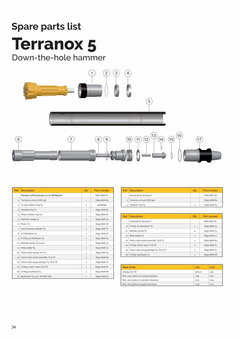
34Epiroc Drilling Tools ABBox 521, SE-737 25 Fagersta, SwedenPhone +46 223 461 00 epiroc.com
6 7 8 9 10 11 12 14 15 1713 16
2 3 4
5
1
Terranox 5Down-the-hole hammer
Ref. Description Qty Part number
Terranox 5 DTH hammer 3 1/2" API Reg Pin 8393 0826 50
1 Terranox 5 chuck DHD 350 1 8393 0826 84
2 O-ring, retainer ring T5 1 95086351
3 Retainer ring T5 1 8393 0826 83
4 Piston retainer ring T5 1 8393 0826 81
5 Hammer casing T5 1 8393 0826 79
6 Piston T5 1 8393 0826 78
7 Inner hammer cylinder T5 1 8393 0826 77
8 Air distributor T5 1 8393 0826 76
9 O-Ring, air distributor T5 1 8393 0826 75
10 Bellville spring T5 (4 pcs) 1 8393 0826 73
11 Wear washer T5 1 8393 0826 72
12 Check valve spring T5 +T6 1 8393 0826 74
13 Check valve body assembly T5 & T6 1 8393 0826 69
14 Check valve plug package T5, T6 & T8 1 8393 0826 71
15 O-Ring, check valve T5 & T6 1 8393 0826 70
16 O-Ring, backhead T5 1 8393 0826 68
17 Backhead T5 3 1/2" API REG PIN 1 8393 0826 67
98
66
024
9 0
1 20
18-0
8.
Wear limits mm inchCasing min. OD 106.40 4.19
Max. worn piston to casing clearance 0.18 0.07
Max. worn piston to cylinder clearance 0.23 0.09
Max. worn piston to guide clearance 0.33 0.13
Ref. Description Qty Part number
Tuning kit for Terranox 5 8393 0827 30
9 O-Ring, air distributor T5 1 8393 0826 75
10 Bellville spring T5 4 8393 0826 73
11 Wear washer T5 1 8393 0826 72
13 Check valve body assembly T5 & T6 1 8393 0826 69
14 O-Ring, check valve T5 & T6 1 8393 0826 71
15 Check valve plug package T5, T6 & T8 1 8393 0826 70
16 O-Ring, backhead T5 1 8393 0826 68
Ref. Description Qty Part number
Service kit for Terranox 5 8393 0827 25
1 Terranox 5 chuck DHD 350 8393 0826 84
3 Retainer ring T5 1 8393 0826 83
Spare parts list

35Epiroc Drilling Tools ABBox 521, SE-737 25 Fagersta, SwedenPhone +46 223 461 00 epiroc.com
9 10
11 12 14 15 1713 16 18 19 20
2 3 4 5
5
6
6
7 8
8
1
Terranox 6Down-the-hole hammer
Ref. Description Qty Part number
Terranox 6 DTH hammer 3 1/2" API Reg Pin 8393 0826 60
1 Terranox 6 chuck DHD 360 1 8393 0827 01
2 O-Ring, retainer ring T6 1 8393 0827 00
3 Retainer ring T6 1 8393 0826 99
4 Bearing surclip T6 1 8393 0826 98
5 Washer retaining 1 50757574
6 Belleville spring T6 (4 pcs) 1 8393 0826 96
7 Bit bearing T6 1 8393 0826 94
8 Cylinder surclip T6 1 8393 0826 95
9 Hammer casing T6 1 8393 0826 86
10 Piston T6 1 8393 0826 93
11 Inner hammer cylinder T6 incl cylinder retainer ring 1 8393 0826 88
12 O-Ring, air distributor T6 1 8393 0826 90
13 Air distributor T6 1 8393 0826 89
14 Check valve spring T5+T6 1 8393 0826 74
15 Spacer washer 1 8393 0826 97
16 Check valve body assembly T5 & T6 1 8393 0826 69
17 Check valve plug package T5, T6 & T8 1 8393 0826 71
18 O-Ring, check valve T5 & T6 1 8393 0826 70
19 O-Ring, backhead T6 1 8393 0826 92
20 Backhead T6 3 1/2" API REG PIN 1 8393 0826 91
98
66
025
0 0
1 20
18-0
8.
Wear limits mm inch
Casing min. OD 127 5
Max. worn piston to casing clearance 0.23 0.009
Max. worn piston to cylinder clearance 0.28 0.011
Max. worn piston to guide clearance 0.38 0.015
Ref. Description Qty Part number
Tuning kit for Terranox 6 8393 0827 31
2 O-Ring, retainer ring T6 1 8393 0827 00
6 Belleville spring T6 4 8393 0826 96
12 O-Ring, air distributor T6 1 8393 0826 90
16 Check valve spring T5+T6 1 8393 0826 69
17 Check valve plug package T5, T6 & T8 1 8393 0826 71
18 O-Ring, check valve T5 & T6 1 8393 0826 70
19 O-Ring, backhead T6 1 8393 0826 92
Breakout washer T6 1 8393 0827 43
Ref. Description Qty Part number
Service kit for Terranox 6 8393 0827 26
1 Terranox 6 chuck DHD 360 1 8393 0827 01
2 O-Ring, retainer ring T6 1 8393 0827 00
3 Retainer ring T6 1 8393 0826 99
Spare parts list

36Epiroc Drilling Tools ABBox 521, SE-737 25 Fagersta, SwedenPhone +46 223 461 00 epiroc.com
9 10 11 12 141316
15 1718
19
2 3 4 5
6
7 8
1
Terranox 8Down-the-hole hammer
Ref. Description Qty Part number
Terranox 8 DTH hammer 4 1/2" API Reg Pin 8393 0826 80
1 Terranox 8 chuck DHD 380 1 8393 0827 21
2 O-Ring, retainer ring T8 1 8393 0827 19
3 Retainer ring T8 1 8393 0827 20
4 Retaining ring piston T8 1 8393 0827 18
5 Piston T8 1 8393 0827 14
6 Hammer casing T8 1 8393 0827 05
7 Cylinder retaining ring T8 1 8393 0827 17
8 Inner Hammer Cylinder T8 1 8393 0827 13
9 O-Ring, air distributor T8 1 8393 0827 12
10 Air distributor T8 1 8393 0827 11
11 Check valve spring T8 1 8393 0827 09
12 Check valve body assembly T8 1 8393 0827 07
13 O-Ring, check valve T8 1 8393 0827 36
14 Belleville spacer 1 8393 0827 10
15 Bellville spring T8 4 8393 0827 16
16 Wear spacer T8 1 8393 0827 22
17 O-Ring for washer 1 8393 0827 15
18 O-Ring, backhead T8 1 8393 0827 06
19 Backhead T8, 4 1/2" API REG PIN 1 8393 0826 85
98
66
025
1 0
1 20
18-0
8.
Wear limits mm inch
Casing min. OD 169.4 6.67
Max. worn piston to casing clearance 0.28 0.011
Max. worn piston to cylinder clearance 0.36 0.014
Max. worn piston to guide clearance 0.33 0.013
Ref. Description Qty Part number
Tuning kit for Terranox 8 8393 0827 32
2 O-Ring, retainer ring T8 1 8393 0827 19
9 O-Ring, air distributor T8 1 8393 0827 12
12 Check valve body assembly T8 1 8393 0827 07
14 O-Ring, check valve T8 1 8393 0827 36
16 Bellville spring T8 4 8393 0827 16
18 O-Ring for washer 1 8393 0827 15
19 O-Ring, backhead T8 1 8393 0827 06
Check valve plug package T5, T6 & T8 1 8393 0827 04
Ref. Description Qty Part number
Service kit for Terranox 8 8393 0827 27
1 Terranox 8 chuck DHD 380 1 8393 0827 21
2 O-Ring, retainer ring T8 1 8393 0827 19
3 Retainer ring T8 1 8393 0827 20
17 Wear spacer T8 1 8393 0827 22
Spare parts list

37
Notes

38
Notes

39
Notes

40
S
ubje
cted
to a
ltera
tions
with
out p
rior n
otic
e. ©
Ter
raro
c Lt
d. A
ll rig
hts
rese
rved
. 201
8.07
.
Customised Geotechnical Solutions.
Full range of drilling tools and consumables for casing advancement systems,
down-the-hole hammers and core drilling, all customised for your needs�
terrarocdrilling�com