geotechnical study foley house relocation ... - houston texas · foley house relocation...
TRANSCRIPT

GEOTECHNICAL STUDY
FOLEY HOUSE RELOCATION
ANNUNCIATION CATHOLIC CHURCH
HOUSTON, TEXAS
Prepared for
TSI Services, LLC
Houston, Texas
September 2014
Prepared by
TOLUNAY-WONG ENGINEERS, INC.
10710 South Sam Houston Parkway West, Suite 100
Houston, Texas 77031
713/722-7064
Project No.: 14.13.181


TWEI 9/5/2014
Report No. 14.13.181
i
TABLE OF CONTENTS
TABLE OF CONTENTS i
ILLUSTRATION AND APPENDIX ii
SUMMARY iii
1. INTRODUCTION 1-1
2. SCOPE OF STUDY 2-1
3. SUBSURFACE CONDITIONS 3-1 3.1 General 3-1 3.2 Regional Geology 3-1 3.3 Soil Stratigraphy 3-1 3.4 Soil Properties 3-1
3.5 Groundwater Observations 3-2
4. GEOTECHNICAL FOUNDATION RECOMMENDATIONS 4-1 4.1 Site Preparation 4-1 4.2 Foundation Design and Construction 4-1
5. CLOSURE 5-1 5.1 Limitations 5-1 5.2 Design Review 5-1
5.3 Construction Surveillance 5-1

TWEI 9/5/2014
Report No. 14.13.181
ii
ILLUSTRATION AND APPENDIX
Illustration
Figure 1 Plan of Borings
Appendix
Appendix A Logs of Borings

TWEI 9/5/2014
Report No. 14.13.181
iii
SUMMARY
This report provides geotechnical recommendations for relocation of the Foley House to the
Annunciation Catholic Church property at 1618 Texas Avenue in Houston, Texas. We
understand that the Foley House will be transported and placed at the location of the existing
rectory structure after it is demolished and removed.
TWEI performed two previous geotechnical studies to evaluate the bell tower distress and
presented the results in two separate reports dated June 22, 2009 (TWEI Project No.: 09.13.047)
and November 20, 2009 (TWEI Project No.: 09.13.119).
The subsurface soils as interpreted from boring B-2 (TWEI Project No.: 09.13.047) consists of
high plasticity cohesive [fat clay (CH)] soils to 22-ft depth, followed by semi-cohesive [silty clay
with sand (CL-ML)] soils to 27-ft depth, underlain by medium plasticity cohesive [lean clay
(CL)] soils to the 40-ft explored depth. The upper about 2-ft thick layer was inferred to be high
plasticity cohesive fill. In boring B-6 (TWEI Project No.: 09.13.119), we encountered 5.5-ft deep
fill material, comprised of high plasticity cohesive sandy fat clays.
The static groundwater level, based on the observed conditions in late April 2009 during our
previous study (TWEI Project No.: 09.13.047), was about 30 ft below existing grade. We
encountered perched water in boring B-6 at the 3.0-ft depth during our previous study in late
October (TWEI Project No.: 09.13.119).
The Foley House may be supported on drilled and underreamed, cast-in-place concrete piers
placed at 12-ft below existing grade. We recommend a net allowable soil bearing pressure of
4,000 psf for pier design. Drilled piers should not be placed closer than preferably three base
diameters, center-to-center.

TWEI 9/5/2014
Report No. 14.13.181
1-1
1. INTRODUCTION
TSI Services, LLC (TSI) retained Tolunay-Wong Engineers, Inc. (TWEI) to perform a
geotechnical study for relocation of the Foley House to the Annunciation Catholic Church
property at 1618 Texas Avenue in Houston, Texas.
This study was conducted in general accordance with TWEI Proposal No. P14-G207 dated July
31, 2014 that was authorized by Mr. Tom Maloney of TSI on August 20, 2014.
Figure 1 presents a plan view of the project site and the approximate locations of the borings
from our previous reports dated June 22, 2009 (TWEI Project No.: 09.13.047) and November 20,
2009 (TWEI Project No.: 09.13.119), that were used for this project.

TWEI 9/5/2014
Report No. 14.13.181
2-1
2. SCOPE OF STUDY
The study included a review of our previous findings at the church property and providing
geotechnical design and construction recommendations to support the Foley House structure,
including:
Site preparation;
Basement backfill requirements;
Foundation design; and
Foundation settlement estimates.
Environmental assessments, and site-specific fault studies were outside the scope of work for this
study.
TWEI 9/5/2014
Report No. 14.13.181
3-1
3. SUBSURFACE CONDITIONS
3.1 General
Our interpretations of soil and groundwater conditions at the site are based on information
obtained at the previous soil boring locations only. The project boring logs are presented in
Appendix A. This information has been used as the basis for our conclusions and
recommendations. Subsurface conditions may vary between soil boring locations. Significant
variations at areas not explored by the project borings will require re-evaluation of our
recommendations.
3.2 Regional Geology
The site is located in an area identified with the Beaumont Formation. Beaumont Formation
includes mainly stream channel, point-bar, natural levee, backswamp, and to a lesser extent
coastal marsh and mud-flat deposits consisting of mostly clay, silt, and sand. Concretions of
calcium carbonate (calcareous nodules) and concentrations of iron oxide and iron-manganese
oxides (ferrous nodules) are commonly found in the zone of weathering. The surface is almost
featureless, characterized by relict river channels shown by meander patterns and pimple mounds
on meanderbelt ridges, separated by areas of low, relatively smooth, featureless backswamp
deposits without pimple mounds. The thickness of the formation is about 100 ft.
In the general site area Beaumont Formation is dominantly clay and mud of low permeability,
high water-holding capacity, high compressibility, high to very high shrink/swell potential, poor
drainage, low shear strength and high plasticity. Geologic units include interdistributary muds,
abandoned channel-fill muds, and overbank fluvial muds.
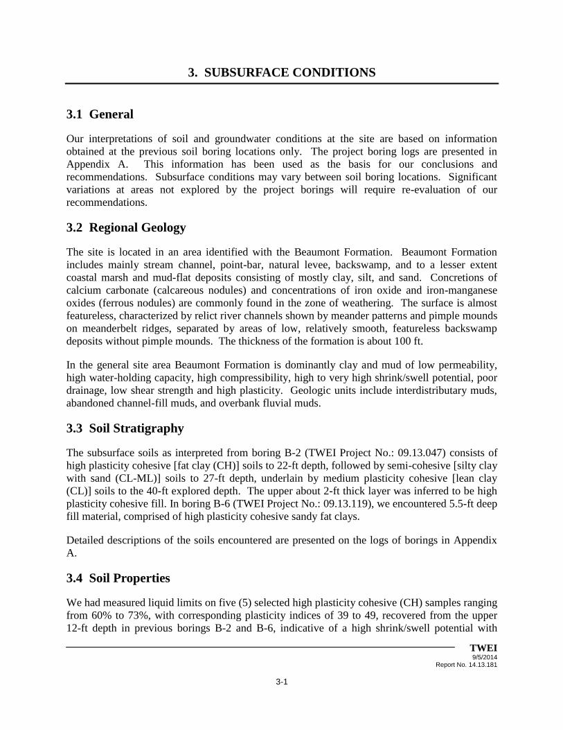
3.3 Soil Stratigraphy
The subsurface soils as interpreted from boring B-2 (TWEI Project No.: 09.13.047) consists of
high plasticity cohesive [fat clay (CH)] soils to 22-ft depth, followed by semi-cohesive [silty clay
with sand (CL-ML)] soils to 27-ft depth, underlain by medium plasticity cohesive [lean clay
(CL)] soils to the 40-ft explored depth. The upper about 2-ft thick layer was inferred to be high
plasticity cohesive fill. In boring B-6 (TWEI Project No.: 09.13.119), we encountered 5.5-ft deep
fill material, comprised of high plasticity cohesive sandy fat clays.
Detailed descriptions of the soils encountered are presented on the logs of borings in Appendix
A.
3.4 Soil Properties
We had measured liquid limits on five (5) selected high plasticity cohesive (CH) samples ranging
from 60% to 73%, with corresponding plasticity indices of 39 to 49, recovered from the upper
12-ft depth in previous borings B-2 and B-6, indicative of a high shrink/swell potential with
TWEI 9/5/2014
Report No. 14.13.181
3-2
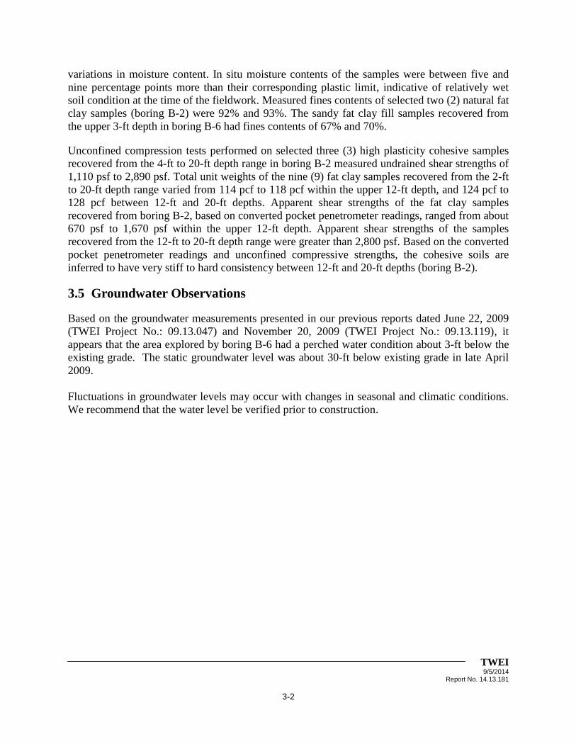
variations in moisture content. In situ moisture contents of the samples were between five and
nine percentage points more than their corresponding plastic limit, indicative of relatively wet
soil condition at the time of the fieldwork. Measured fines contents of selected two (2) natural fat
clay samples (boring B-2) were 92% and 93%. The sandy fat clay fill samples recovered from
the upper 3-ft depth in boring B-6 had fines contents of 67% and 70%.
Unconfined compression tests performed on selected three (3) high plasticity cohesive samples
recovered from the 4-ft to 20-ft depth range in boring B-2 measured undrained shear strengths of
1,110 psf to 2,890 psf. Total unit weights of the nine (9) fat clay samples recovered from the 2-ft
to 20-ft depth range varied from 114 pcf to 118 pcf within the upper 12-ft depth, and 124 pcf to
128 pcf between 12-ft and 20-ft depths. Apparent shear strengths of the fat clay samples
recovered from boring B-2, based on converted pocket penetrometer readings, ranged from about
670 psf to 1,670 psf within the upper 12-ft depth. Apparent shear strengths of the samples
recovered from the 12-ft to 20-ft depth range were greater than 2,800 psf. Based on the converted
pocket penetrometer readings and unconfined compressive strengths, the cohesive soils are
inferred to have very stiff to hard consistency between 12-ft and 20-ft depths (boring B-2).
3.5 Groundwater Observations
Based on the groundwater measurements presented in our previous reports dated June 22, 2009
(TWEI Project No.: 09.13.047) and November 20, 2009 (TWEI Project No.: 09.13.119), it
appears that the area explored by boring B-6 had a perched water condition about 3-ft below the
existing grade. The static groundwater level was about 30-ft below existing grade in late April
2009.
Fluctuations in groundwater levels may occur with changes in seasonal and climatic conditions.
We recommend that the water level be verified prior to construction.

TWEI 9/5/2014
Report No. 14.13.181
4-1
4. GEOTECHNICAL FOUNDATION RECOMMENDATIONS
The engineering analyses presented herein are based on the results of the previous project
borings and laboratory tests.
4.1 Site Preparation
We understand that the Foley House will be transported and placed at the location of the existing
rectory structure after it is demolished and removed. Furnished information indicates that the
south half of the existing rectory is occupied by a basement about 8-ft deep. The basement will
also be demolished, removed, and backfilled (walls and floor slab will be removed).
After removal of the existing foundations and the basement, general recommendations given
below should be followed.
1. The area within construction lines, outside the basement limits should be stripped to at
least 6 in. to effectively remove topsoil, vegetation, and debris, if present. Tree roots
should be grubbed to full depth. The grub holes should be backfilled with compacted soil
similar to adjacent in situ soils in classification, moisture, and density.
2. The site should be graded such that positive surface drainage away from work areas is
established and maintained at all times. Water must not be allowed to pond on the surface
during construction. Positive drainage (away from the building) should be maintained
throughout the life of the structure to prevent water from collecting near it.
3. Backfill material should be imported homogeneous clay with a plasticity index (PI)
between 7 and 20, and liquid limit less than 40%. All fill should be placed on competent
surfaces in lifts not exceeding 8-in. loose measure. The fill should be compacted to at
least 95% of the standard Proctor maximum dry density at moisture content within two
percentage points of the optimum (ASTM D 698). We suggest that any fill placement be
tested and documented by the Geotechnical Engineer or a representative.
Bedding and backfill for below grade utility trenches within structure footprint, if planned, should
be cement-stabilized sand or cohesive fill. Cement stabilized sand should meet the requirements of
the Texas Department of Transportation Specifications, Item 400. Sand should not be used as
trench bedding or backfill within 10 ft of the structure.
4.2 Foundation Design and Construction
This report section addresses foundation design and construction recommendations to support
the transported Foley House, based primarily upon soils encountered in boring B-2 (TWEI
Project No.: 09.13.047). We understand that the north half of the foundation system will be on
existing soil and the south half will be on backfill material. To minimize the differential
settlement, we recommend to support the building on a drilled and underreamed, cast-in-place
concrete pier foundation.
TWEI 9/5/2014
Report No. 14.13.181
4-2
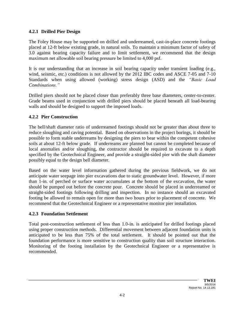
4.2.1 Drilled Pier Design
The Foley House may be supported on drilled and underreamed, cast-in-place concrete footings
placed at 12-ft below existing grade, in natural soils. To maintain a minimum factor of safety of
3.0 against bearing capacity failure and to limit settlement, we recommend that the design
maximum net allowable soil bearing pressure be limited to 4,000 psf.
It is our understanding that an increase in soil bearing capacity under transient loading (e.g.,
wind, seismic, etc.) conditions is not allowed by the 2012 IBC codes and ASCE 7-05 and 7-10
Standards when using allowed (working) stress design (ASD) and the “Basic Load
Combinations.”
Drilled piers should not be placed closer than preferably three base diameters, center-to-center.
Grade beams used in conjunction with drilled piers should be placed beneath all load-bearing
walls and should be designed to support the imposed loads.
4.2.2 Pier Construction
The bell/shaft diameter ratio of underreamed footings should not be greater than about three to
reduce sloughing and caving potential. Based on observations in the project borings, it should be
possible to form stable underreams by designing the piers to bear within the competent cohesive
soils at about 12-ft below grade. If underreams are planned but cannot be completed because of
local anomalies and/or sloughing, the contractor should be required to excavate to a depth
specified by the Geotechnical Engineer, and provide a straight-sided pier with the shaft diameter
possibly equal to the design bell diameter.
Based on the water level information gathered during the previous fieldwork, we do not
anticipate water seepage into pier excavations due to static groundwater level. However, if more
than 1-in. of perched or surface water accumulates at the bottom of the excavation, the water
should be pumped out before the concrete pour. Concrete should be placed in underreamed or
straight-sided footings following drilling and inspection. In no instance should an excavated
footing be allowed to remain open for more than two hours prior to placement of concrete. We
recommend that the Geotechnical Engineer or a representative monitor pier installation.
4.2.3 Foundation Settlement
Total post-construction settlement of less than 1.0-in. is anticipated for drilled footings placed
using proper construction methods. Differential movement between adjacent foundation units is
anticipated to be less than 75% of the total settlement. It should be pointed out that the
foundation performance is more sensitive to construction quality than soil structure interaction.
Monitoring of the footing installation by the Geotechnical Engineer or a representative is
recommended.

TWEI 9/5/2014
Report No. 14.13.181
4-3
4.2.4 Variations During Construction
The recommendation to consider underreamed footings is based on the observed subsurface
conditions in the previous project borings. This exploration does not eliminate possible presence
of zones within the subsurface stratigraphy that would not support underream construction.

TWEI 9/5/2014
Report No. 14.13.181
5-1
5. CLOSURE
5.1 Limitations
This report has been prepared for the exclusive use of TSI Services, LLC for specific application
to relocate the Foley House at the aforementioned location in Houston, Texas. Our report has
been prepared in accordance with generally accepted geotechnical engineering practice common
to the local area. No other warranty, express or implied, is made.
The analyses and recommendations contained in this report are based on the data obtained from
the referenced previous subsurface explorations. The borings indicated subsurface conditions
only at the specific locations and times, and only to the depths penetrated. The borings do not
necessarily reflect strata variations that may exist between boring locations. The validity of the
recommendations is based in part on assumptions about the stratigraphy made by the
Geotechnical Engineer. Such assumptions may be confirmed only during earthwork and
construction. If subsurface conditions different from those described are noted during
construction, recommendations in this report must be reevaluated.
If any changes in the nature, design, or location of the proposed project are planned, the
conclusions and recommendations contained in this report should not be considered valid unless
the changes are reviewed and conclusions of this report are modified or verified in writing by
TWEI. TWEI is not responsible for any claims, damages, or liability associated with
interpretation of subsurface data or reuse of the subsurface data or engineering analyses without
the expressed written authorization of TWEI.
5.2 Design Review
Geotechnical review of the design and construction plans as well as the specifications should be
performed by TWEI before release. The review is aimed at determining if the geotechnical
design recommendations and construction criteria presented in this report have been properly
interpreted. Design review is not within the scope of work authorized for this study.
5.3 Construction Surveillance
Surveillance of the site preparation work, fill placement/compaction and pier installation is
recommended. These field services are required to check for changed conditions that may result
in modifications to our recommendations. The quality of the construction practices will affect
foundation performance and should be monitored.

ILLUSTRATION


APPENDIX A LOGS OF BORINGS
(TWEI PROJECT NO.: 09.13.047 AND 09.13.119)

0
5
10
15
20
25
30
2.50
1.00
1.50
1.50
2.50
1.75
4.25
4.50
4.50
4.50
2.00
4.50
Stiff dark gray FAT CLAY w/ SAND "FILL"
Firm dark gray FAT CLAY (CH)w/ ferrous nodules
-stiff @ 4'-12'-dark gray & tan @ 4'-8'
-tan & reddish brown @ 8'-10'-w/ calcareous nodules @ 8'-12'
-red & tan below 10'
-very stiff, slickensided @ 12'-14'
-very stiff to hard @ 14'-18'
-w/ calcareous nodules @ 16'-20'
-very stiff @ 18'-20'
Firm light gray SILTY CLAY w/ SAND (CL-ML)w/ ferrous nodules
Very stiff to hard light gray & tan LEAN CLAY (CL)w/ ferrous & calcareous nodules
20
29
31
26
32
29
22
24
20
24
16
11
90
90
94
87
90
105
100
106
102
114
115
1.10
1.99
2.89
0.78
13
2
5
6
*
60
70
73
21
39
49
49
5
92
93
80
TOLUNAY-WONG ENGINEERS, INC.
LOG OF BORING B-2
Project: Annunciation Catholic Church - Bell Tower Stabilization1618 Texas, Houston, Texas
Project No.: 09.13.047Date: 04-30-2009
Client: Archdiocese of Galveston-Houstonc/o Walter P. Moore and Associates, Inc. Houston, Texas
Elevation:
Dry Augered: 0 to 40 ft Free Water During Drilling at: 38 ft (1)Washed Bored: to ft Water at: 29.9 ft after 20 hours (2) Caving at: 31.2 ft
Note(s): (1) Water level in the open borehole rose to 29.0-ft depth, with cavingdepth of 36.0-ft, 2.5 hours after completion of sampling.(2) Open borehole backfilled with soil cuttings.
ELEVATION/DEPTH
SOIL/SAMPLERSYMBOLS
& FIELD DATA
POCKETPEN. (tsf)
or SPTDESCRIPTION
Wc(%)
Dens.(pcf)
Qu or UU(tsf)
Str.(%)
LL PIPass#200(%)
page 1 of 2

30
35
40
45
50
55
60
4.50
4.50
Very stiff to hard light gray & tan LEAN CLAY (CL)w/ ferrous & calcareous nodules
-w/ sand pockets @ 33'-35'
-reddish brown & gray, w/ silt pockets @ 38'-40'
Boring terminated @ 40 ft
17
20
109
110
47
30
29
11
98
91
TOLUNAY-WONG ENGINEERS, INC.
LOG OF BORING B-2
Project: Annunciation Catholic Church - Bell Tower Stabilization1618 Texas, Houston, Texas
Project No.: 09.13.047Date: 04-30-2009
Client: Archdiocese of Galveston-Houstonc/o Walter P. Moore and Associates, Inc. Houston, Texas
Elevation:
Dry Augered: 0 to 40 ft Free Water During Drilling at: 38 ft (1)Washed Bored: to ft Water at: 29.9 ft after 20 hours (2) Caving at: 31.2 ft
Note(s): (1) Water level in the open borehole rose to 29.0-ft depth, with cavingdepth of 36.0-ft, 2.5 hours after completion of sampling.(2) Open borehole backfilled with soil cuttings.
ELEVATION/DEPTH
SOIL/SAMPLERSYMBOLS
& FIELD DATA
POCKETPEN. (tsf)
or SPTDESCRIPTION
Wc(%)
Dens.(pcf)
Qu or UU(tsf)
Str.(%)
LL PIPass#200(%)
page 2 of 2

0
2.5
5
7.5
10
12.5
15
1.00
1.00
0.75
0.25
9.5" Concrete slab
Firm gray SANDY FAT CLAY "FILL"w/ ferrous nodules-w/ brick pieces @ 1'-2'
-very soft, red & gray, mostly brick pieces below 4.5'
-w/ roots @ 5'-5.5'
Boring terminated @ 5.5 ft
26
30
33
41
60
61
66
41
45
67
70
TOLUNAY-WONG ENGINEERS, INC.
LOG OF BORING B-6
Project: Annunciation Catholic Church - Foundation Stabilization1618 Texas Avenue, Houston, Texas
Project No.: 09.13.119Date: 10.22.2009
Client: Archdiocese of Galveston-Houstonc/o Walter P. Moore and Associates, Inc., Houston, Texas
Elevation:
Dry Augered: 0 to 5.5 ft Free Water During Drilling at: 4.5 ft (1)Washed Bored: to ft Water at: 3.0 ft after 3 days (2) Caving at: 3.6 ft
Note(s): (1) Water level in the open borehole rose to 3.0 ft depth, 10minutes after encountering free water.(2) Open borehole backfilled with soil cuttings. Top concretepatched with grout.(3) Boring terminated at the 5.5 ft depth upon encountering refusalfo further augering on what appeared to be brick.
page 1 of 1
ELEVATION/DEPTH
SOIL/SAMPLERSYMBOLS
& FIELD DATA
POCKETPEN. (tsf)
or SPTDESCRIPTION
Wc(%)
Dens.(pcf)
Qu or UU(tsf)
Str.(%)
LL PIPass#200(%)