geotechnical report - route 1 sidewalk over powells creek ... · into undisturbed soil under the...
TRANSCRIPT

Geotechnical Engineering Report
Proposed Pedestrian Bridge for Route 1 Sidewalk over Powells
Creek, Dumfries, Virginia
December 10, 2015
Revision 1 (February 2, 2016)
19955 Highland Vista Drive, Suite 170Ashburn, VA 20147Phone 703 726 8030 ● www.geoconcepts-eng.com
Page 1 of 140 Pages

19955 Highland Vista Dr., Suite 170 Ashburn, Virginia 20147
(703) 726-8030 www.geoconcepts-eng.com
December 18, 2015 Revision: 1 (February 2, 2016) Mr. Steve Kuntz, PE Dewberry 8401 Arlington Boulevard Fairfax, Virginia 22031
Subject: Geotechnical Engineering Report, Proposed Pedestrian Bridge for Route 1 Sidewalk over Powells Creek, Dumfries, Virginia (GeoConcepts Project No. 14156)
Dear Mr. Kuntz:
GeoConcepts Engineering, Inc. (GeoConcepts) is pleased to present the following geotechnical engineering report prepared for the proposed pedestrian bridge for the Route 1 sidewalk over Powells Creek located in Dumfries, Prince William County, Virginia. We appreciate the opportunity to serve as your geotechnical consultant on this project. Please do not hesitate to contact me if you have any questions or want to meet to discuss the findings and recommendations contained in the report. Sincerely,
GEOCONCEPTS ENGINEERING, INC. Deniz Karadeniz, PhD, PG, PE Senior Engineer [email protected]
Page 2 of 140 Pages
Table of Contents 1.0 Scope of Services ....................................................................................................................... 1 2.0 Site Description and Proposed Construction .................................................................................. 1 3.0 Subsurface Conditions ................................................................................................................ 2
3.1 Geology ........................................................................................................................... 2 3.2 Stratification .................................................................................................................... 2 3.3 Groundwater .................................................................................................................... 3 3.4 Soil Laboratory Test Results .............................................................................................. 3 3.5 Gradation Testing for Scour Analysis .................................................................................. 5
4.0 Engineering Analysis ................................................................................................................... 5 4.1 Drilled Shaft Axial Compression Resistance ......................................................................... 5 4.2 Drilled Shaft Lateral Capacity Analysis ................................................................................ 6 4.3 Drilled Shaft Installations .................................................................................................. 6 4.4 Abutment Backwall Design ................................................................................................ 7 4.5 Earthwork ........................................................................................................................ 7
5.0 General Limitations ..................................................................................................................... 8 Figure 1: Site Vicinity Map Appendix A: Subsurface Investigation Appendix B: Soil Laboratory Test Results Appendix C: Engineering Analysis Appendix D: Bridge Plans
Page 3 of 140 Pages

Revision 1 - February 2, 2016 14156 Page 1
1.0 Scope of Services This geotechnical engineering report presents the results of the field investigation, soil laboratory testing, and engineering analysis of the geotechnical data. This report specifically addresses the following:
An evaluation of subsurface conditions along the proposed pedestrian bridge alignment, including comments on corrosivity potential of the on-site soils.
Recommendations for drilled shaft foundations to support the proposed bridge abutments, and abutment backwall design.
Earthwork recommendations for construction of loadbearing fills, including an assessment of on-site soils to be excavated for re-use as fill.
Services not specifically identified in the contract for this project are not included in the scope of services.
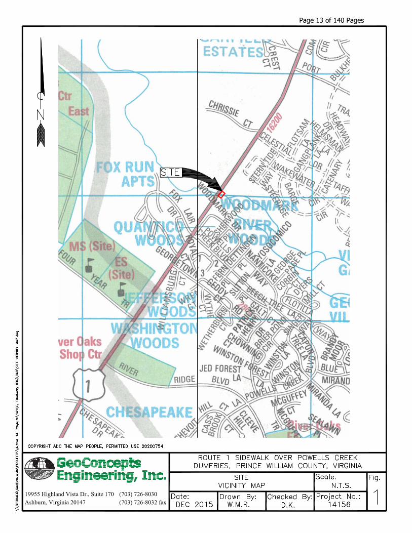
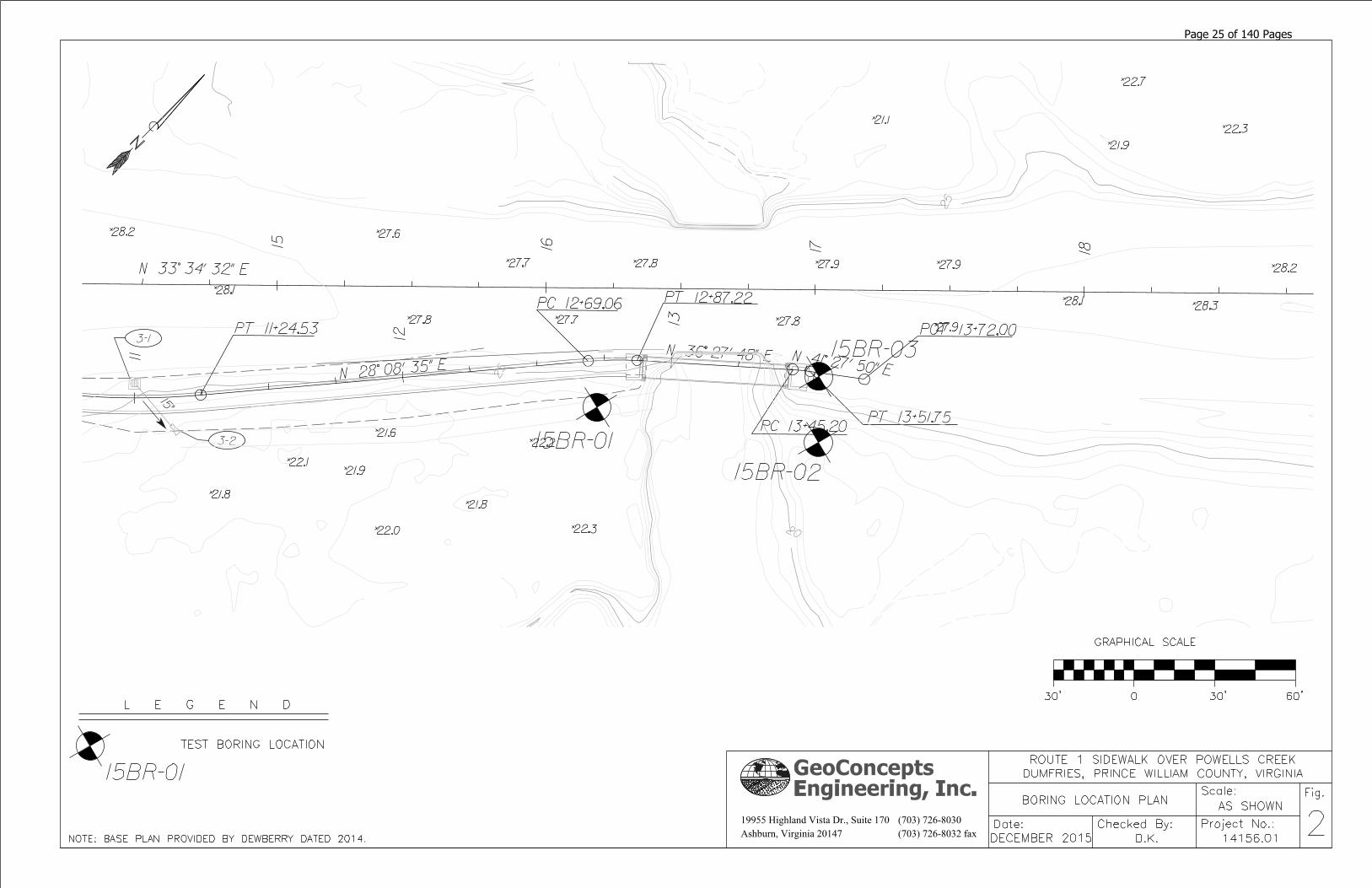
2.0 Site Description and Proposed Construction The site is located at the intersection of Route 1 and Powells Creek in Dumfries, Prince William County, Virginia. A site vicinity map is presented as Figure 1 at the end of this report. The site landscape is heavily wooded, and sloped with elevations varying from elevation (EL) 20 to EL 27 towards the roadway. The stream banks are located at approximately EL 18 and the stream bottom is approximately at EL 16. An existing sidewalk runs along the east side of Route 1 and ends approximately 20 feet north of Powells Creek. Based on information provided to us, we understand that the proposed construction consists of a new single span pedestrian bridge that connects the southwest sidewalk to the northeast sidewalk along Route 1 over Powell’s Creek. The table below presents a summary of the proposed bridge details as provided in the bridge plans by Dewberry dated 18 December 2015, which are included in Appendix D of this report.
Table 2.0-1: Pedestrian Bridge Details Approx. Begin
Station Approx. End
Station No. of Spans
Total Length (feet)
Width (feet)
12+89 13+44 1 55 7.5
We understand that up to 3 feet of fill is required to construct the new approach embankment for Abutment A and up to 4 feet of fill is required to construct the new approach embankment for Abutment B. We understand that deep foundations consisting of drilled shafts are planned to support the proposed bridge abutments. The foundation loads at the bridge abutment locations provided to us by Dewberry are summarized in the table below.
Table 2.0-2: Foundation Loads
Load Cases1
Abutment A Abutment B
Horizontal, Fz (kips)
Vertical, Fy (kips)
Moment2, Mx (kip-
ft)
Horizontal, Fz (kips)
Vertical, Fy (kips)
Moment2, Mx (kip-
ft)
Load Case 1: Fy Maximum Strength I 23.3 167.6 92.7 14.9 148.6 77.3
Load Case 2: Fy Minimum Strength III 28.7 96.9 129.9 20.6 83.1 95.6
Page 4 of 140 Pages

Revision 1 - February 2, 2016 14156 Page 2
Load Cases1
Abutment A Abutment B
Horizontal, Fz (kips)
Vertical, Fy (kips)
Moment2, Mx (kip-
ft)
Horizontal, Fz (kips)
Vertical, Fy (kips)
Moment2, Mx (kip-
ft)
Load Case 3: Mx Maximum Strength III 28.7 135.6 128.6 20.6 116.5 99.4
Load Case 4: Service Service I 18.9 124.3 87.2 13.3 109.4 72.0
Notes: 1. Load Cases are shown as described in L-Pile analysis. 2. Moment acts in the same direction as the horizontal load.
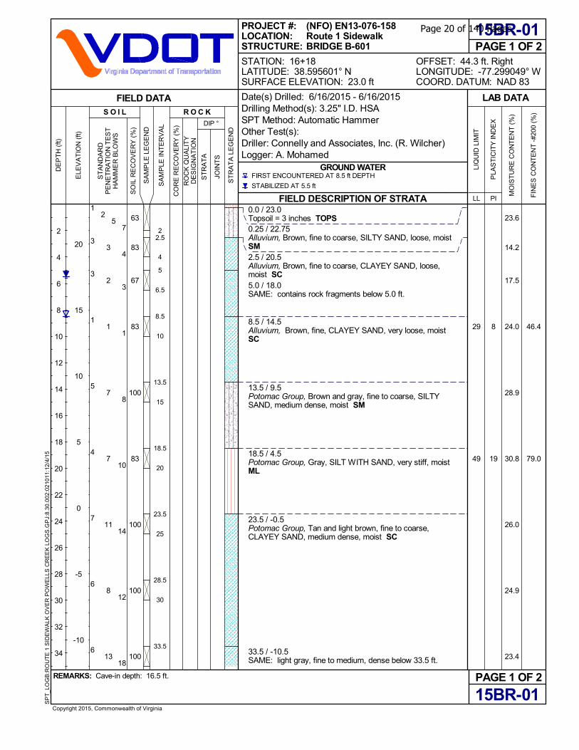
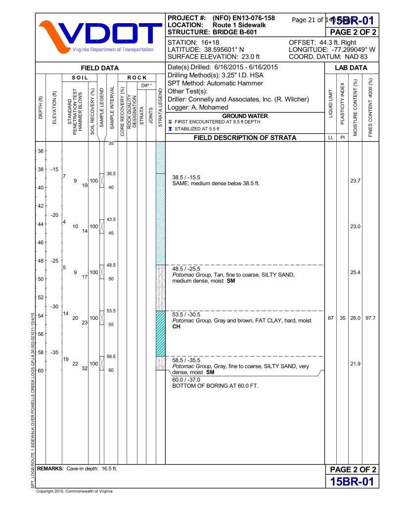
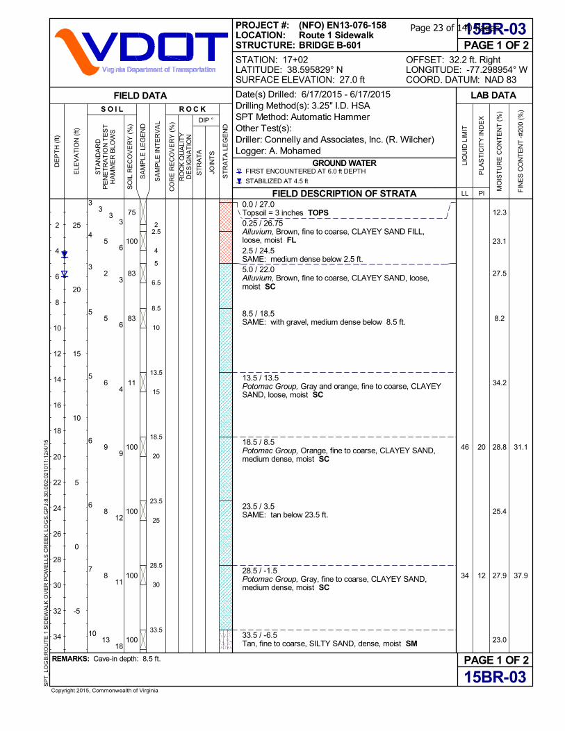
3.0 Subsurface Conditions Subsurface conditions were investigated by drilling a total of three Standard Penetration Test (SPT) borings in the proposed bridge areas. Test boring logs and a boring location plan are presented in Appendix A of this report. The SPT borings were completed by Connelly and Associates Inc. of Manassas, Virginia under our observation between June 16 and June 17, 2015, utilizing 3-¼-inch inside diameter hollow stem auger with automatic hammer. The sampler was advanced by driving the spoon a distance of 18 or 24 inches into undisturbed soil under the impact of a 140-lbf hammer free-falling 30 inches height per ASTM D1586-11. The borings were staked and surveyed by Dewberry in advance of our work. The offset distances were estimated in the field by GeoConcepts. Test boring logs and a subsurface exploration plan are presented in Appendix A of this report. As stated in AASHTO Section C10.4.6.2.4, a hammer efficiency of 80 percent for the automatic trip hammer was used to correct the SPT N values for hammer efficiency. A summary of relevant test borings at each substructure is provided in the table below.
Table 3.0-1: Summary of Relative Test Borings
Substructure Location Relevant Test Boring
Abutment A 15BR-01
Abutment B 15BR-02, 15BR-03
3.1 Geology The site is located within the Coastal Plain Physiographic Province of Virginia. The Coastal Plain consists of a seaward thickening wedge of unconsolidated to semi-consolidated sedimentary deposits from the Cretaceous Geologic Period to the Holocene Geologic Epoch. These deposits represent marginal-marine to marine sediments consisting of interbedded sands and clays. The Coastal Plain is bordered to the east by the Atlantic Ocean and to the west by the Piedmont Physiographic Province. The dividing line between the Coastal Plain and the Piedmont is locally referred to as the “Fall Line”. This name comes from the waterfalls that form as a result of the differential erosion that occurs as streams cross the Piedmont/Coastal Plain contact.
3.2 Stratification The subsurface materials encountered have been stratified for purposes of our discussions herein. These stratum designations do not imply that the materials encountered are continuous across the site. Stratum designations have been established to characterize similar subsurface conditions based on material gradations and parent geology. The subsurface materials encountered in the test borings completed at the site have been assigned to the strata presented herein.
Page 5 of 140 Pages

Revision 1 - February 2, 2016 14156 Page 3
Stratum A (Existing Fill)
loose to medium dense, clayey sand FILL (FL), moist, brown. This stratum was only encountered in test boring 15BR-03 up to 5 feet depth. The corrected blow counts (N60) varied from 8 blows per foot (bpf) to 12 bpf.
Stratum B (Alluvium)
very loose to medium dense, or soft, clayey SAND (SC), silty SAND (SM), and LEAN CLAY (CL), moist, brown and brown-orange. The corrected blow counts (N60) varied from 2 blows per foot (bpf) to 22 bpf.
Stratum C (Potomac)
loose to very dense, or hard, clayey SAND (SC), silty SAND (SM), LEAN CLAY (CL), FAT CLAY (CH), SILT (ML), moist, gray-tan, orange, and gray-brown. The corrected blow counts (N60) varied from 13 blows per foot (bpf) to 46 bpf.
The two letter designations included in the strata descriptions presented above and on the test boring logs represent the Unified Soil Classification System (USCS) group symbol and group name for the samples based on laboratory testing per ASTM D-2487 and visual classifications per ASTM D-2488. It should be noted that visual classifications per ASTM D-2488 may not match classifications determined by laboratory testing per ASTM D-2487.
3.3 Groundwater Groundwater level observations were made in the field during drilling and up to one day after the completion of the select test borings. A summary of the water level readings is presented in the table below.
Table 3.3-1: Summary of Groundwater Readings
Test Boring
No.
Ground Surface
Elevation (feet)
Depth to Groundwater (feet) Groundwater Elevation (feet)
First Encountered
After 24 or Longer Hours
First Encountered
After 24 or Longer Hours
15BR-01 23.0 8.5 5.5 14.5 17.5
15BR-02 22.0 6.0 4.5 16.0 17.5
15BR-03 27.0 6.0 4.5 21.0 22.5
The groundwater observations presented herein are considered to be an indication of the groundwater levels at the dates and times indicated. However, please note that water levels were taken subsequent to a significant rainfall event and may represent surface water that entered into the boreholes. Where more impervious silt/clay soils are encountered, the amount of water seepage into the borings is limited, and it is generally not possible to establish the location of the groundwater table through short term water level observations. Accordingly, the groundwater information presented herein should be used with caution. Also, fluctuations in groundwater levels should be expected with seasons of the year, construction activity, changes to surface grades, precipitation, or other similar factors.
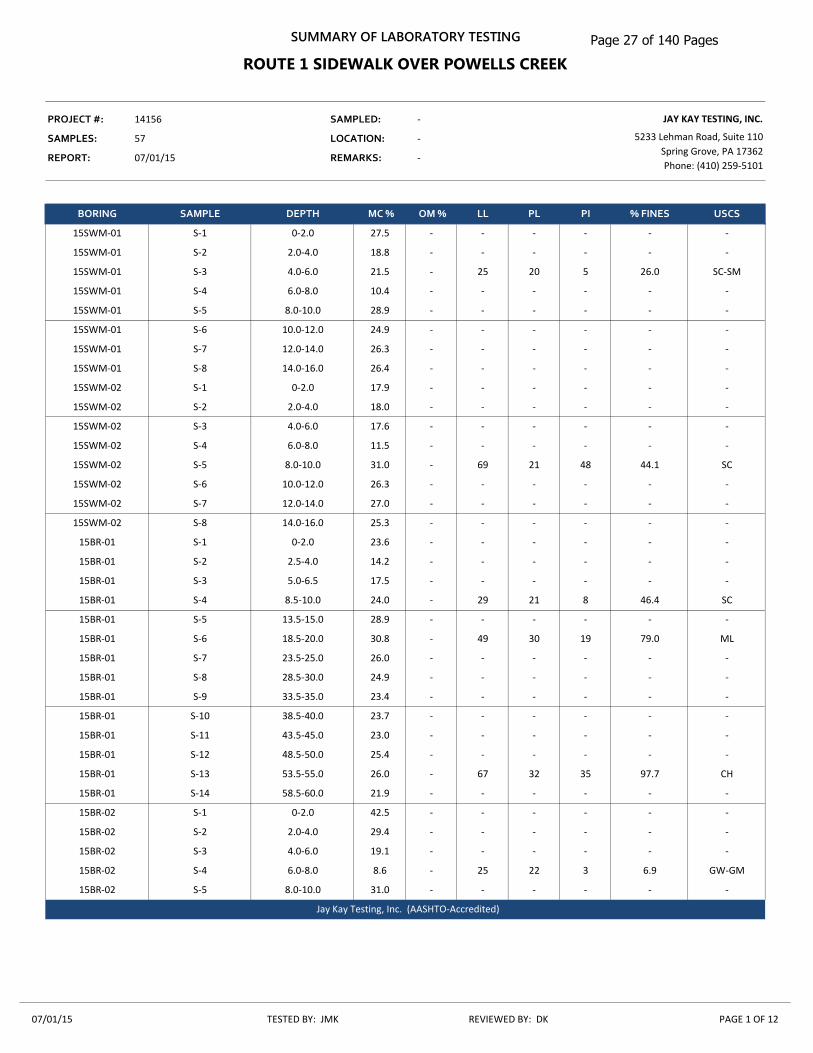
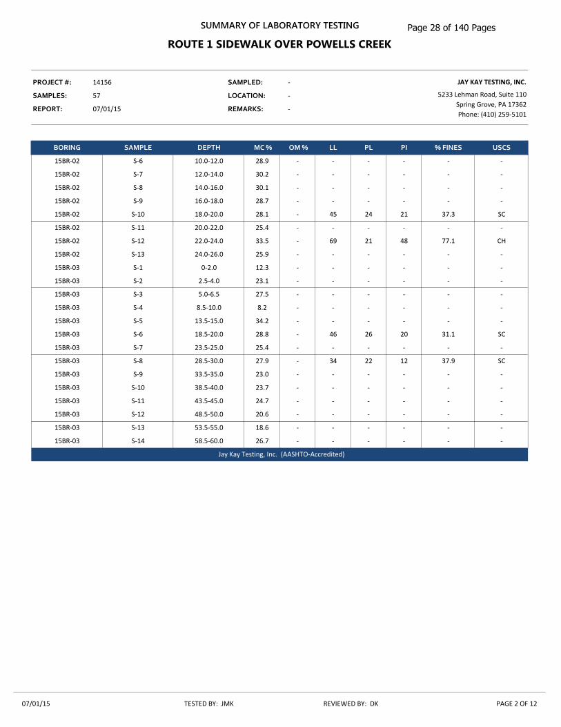
3.4 Soil Laboratory Test Results Selected soil samples obtained from the field investigation were tested for natural moisture content, grain size distribution, Atterberg limits, and metal corrosion and concrete attack potential. A summary of soil laboratory test results and individual soil laboratory test results are presented in Appendix B. The results of natural moisture content and Atterberg limits tests are also presented on the test boring logs in Appendix A.
Page 6 of 140 Pages
Revision 1 - February 2, 2016 14156 Page 4
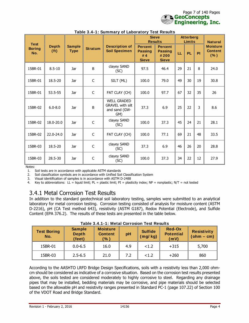
Table 3.4-1: Summary of Laboratory Test Results
Test Boring
No.
Depth (ft)
Sample Type Stratum Description of
Soil Specimen
Sieve Results
Atterberg Limits Natural
Moisture Content
(%)
Percent Passing
#4 Sieve
Percent Passing #200 Sieve
LL PL PI
15BR-01 8.5-10 Jar B clayey SAND (SC) 97.5 46.4 29 21 8 24.0
15BR-01 18.5-20 Jar C SILT (ML) 100.0 79.0 49 30 19 30.8
15BR-01 53.5-55 Jar C FAT CLAY (CH) 100.0 97.7 67 32 35 26
15BR-02 6.0-8.0 Jar B
WELL GRADED GRAVEL with silt and sand (GW-
GM)
37.3 6.9 25 22 3 8.6
15BR-02 18.0-20.0 Jar C clayey SAND (SC) 100.0 37.3 45 24 21 28.1
15BR-02 22.0-24.0 Jar C FAT CLAY (CH) 100.0 77.1 69 21 48 33.5
15BR-03 18.5-20 Jar C clayey SAND (SC) 37.3 6.9 46 26 20 28.8
15BR-03 28.5-30 Jar C clayey SAND (SC) 100.0 37.3 34 22 12 27.9
Notes: 1. Soil tests are in accordance with applicable ASTM standards 2. Soil classification symbols are in accordance with Unified Soil Classification System 3. Visual identification of samples is in accordance with ASTM D-2488 4. Key to abbreviations: LL = liquid limit; PL = plastic limit; PI = plasticity index; NP = nonplastic; N/T = not tested
3.4.1 Metal Corrosion Test Results In addition to the standard geotechnical soil laboratory testing, samples were submitted to an analytical laboratory for metal corrosion testing. Corrosion testing consisted of analysis for moisture content (ASTM D-2216), pH (CA Test method 643), resistivity (ASTM G187), Redox Potential (Electrode), and Sulfide Content (EPA 376.2). The results of these tests are presented in the table below.
Table 3.4.1-1: Metal Corrosion Test Results
Test Boring No.
Sample Depth (feet)
Moisture Content
(%) pH Sulfide
(mg/kg)
Red-Ox Potential
(mV)
Resistivity (ohm – cm)
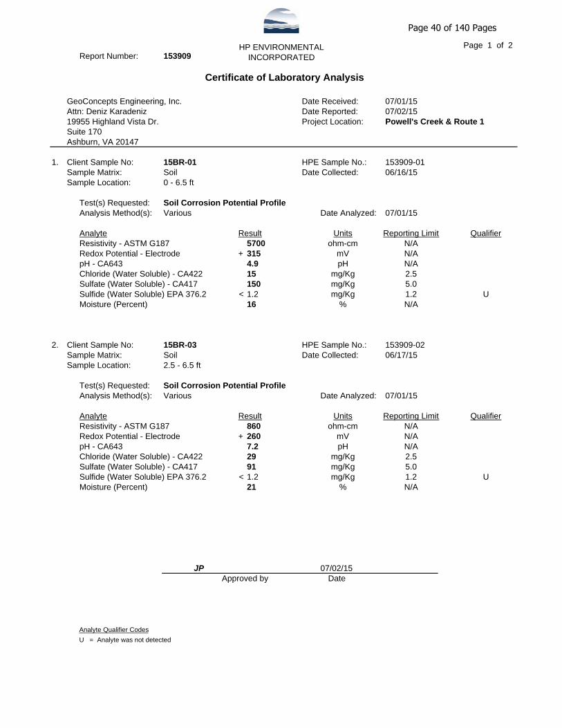
15BR-01 0.0-6.5 16.0 4.9 <1.2 +315 5,700
15BR-03 2.5-6.5 21.0 7.2 <1.2 +260 860
According to the AASHTO LRFD Bridge Design Specifications, soils with a resistivity less than 2,000 ohm-cm should be considered as indicative of a corrosive situation. Based on the corrosion test results presented above, the soils tested are considered moderately to highly corrosive to steel. Regarding any drainage pipes that may be installed, bedding materials may be corrosive, and pipe materials should be selected based on the allowable pH and resistivity ranges presented in Standard PC-1 (page 107.22) of Section 100 of the VDOT Road and Bridge Standard.
Page 7 of 140 Pages

Revision 1 - February 2, 2016 14156 Page 5
3.4.2 Concrete Attack Test Results Sulfate (CA 417) testing was performed on selected soil samples to determine the severity of sulfate attack on concrete. The results of sulfate testing are presented in the table below. According to the AASHTO LRFD Bridge Design Specifications, soils with sulfate concentrations greater than 1,000 parts per million (ppm) should be considered as indicative of potential deterioration of concrete. The table below presents comments on potential concrete deterioration based on ACI 318.
Table 3.4.2-1: Concrete Attack Test Results
Test Boring No. Sample Depth (feet) Sulfate (ppm) Potential Deterioration to Concrete
15BR-01 0.0-6.5 150 No
15BR-03 2.5-6.5 91 No
3.5 Gradation Testing for Scour Analysis Gradation testing was performed on bulk samples collected from test boring BR-02 to aid in the evaluation of scour potential. Resulting D90, D84, and D50 test results are presented in the table below.
Table 3.5-1: Gradation Test Results
Test Boring No.
Soil Classification
Depth (ft)
D90
(mm) D85
(mm) D50
(mm)
15BR-02
GW-GM 6-8 22.2 18 10
SC 10.5-11 0.35 0.32 0.18
SC 18-20 0.26 0.24 0.13
CH 22-24 0.3 0.16 0.012
4.0 Engineering Analysis Recommendations regarding drilled shaft foundations, abutment backwall design, and earthwork are presented herein.
4.1 Drilled Shaft Axial Compression Resistance Drilled shafts consists of circular, straight shaft, cast-in-place reinforced concrete elements designed to develop their load carrying capacity from a combination of frictional resistance and end bearing resistance. We understand that the project team is considering 4 feet diameter drilled shafts to support the pedestrian bridge abutments. Scour depths at each abutment were provided by Dewberry, and these depths and corresponding elevations are summarized in the table below.
Table 4.1-1: Scour Information
Structure Scour Depth from
Top of Drilled Shaft (ft)
Scour Elevation (ft)
Abutment A 9.6 EL 8.2
Abutment B 11.7 EL 8.4
Page 8 of 140 Pages

Revision 1 - February 2, 2016 14156 Page 6
The nominal (unfactored) and factored tip and side resistances as calculated based on AASHTO LRFD Specification 2012 are presented in the table below. The computations for nominal unit tip resistance and unit side resistance are provided in Appendix C. AASHTO resistance factors of 0.55 and 0.50 were used for side shear and tip resistance for sand, respectively. Resistance factors of 0.45 and 0.4 were used for side shear and tip resistance for clay, respectively. The soil above the scour depths were excluded from the factored axial compression resistance computations.
Table 4.1-2: Axial Compression Resistance of Drilled Shafts
Substructure Shaft
Diameter (ft)
Top of Shaft
Elevation (ft)
Estimated Drilled Shaft End Bearing
Elevation/ Length1
Factored Axial Load, Qp (kips)2
Factored Axial
Resistance (kips)
CDR3
Abutment A 4 17.8 EL -22.2 / 40 ft 168 308 1.83
Abutment B 4 20.1 EL -23.9 / 44 ft 148 340 2.30
Notes: 1. Length of the drilled shaft is controlled by the lateral analysis. 2. Maximum factored load is selected from Table 2.0-2. 3. CDR is Capacity Demand Ratio = Factored Axial Resistance/Factored Compressional Load (Qp).
Based on the results of our analyses, we estimate total settlement to be less than 0.5-inch provided that proper installation is performed and that the above-indicated design recommendations have been followed.
4.2 Drilled Shaft Lateral Capacity Analysis Lateral capacities have been analyzed with the computer software programs Lpile version 2015-8.02 developed by Ensoft. Lateral capacities and deflections have been developed assuming that the shaft head is free to move. The lateral analyses were performed using the structural loads provided in Table 2.0-2. The results of the lateral analyses are summarized in the table below and the calculations are provided in Appendix C. Based on the discussion with Dewberry, a horizontal deflection less than 1-inch is acceptable for service limit state; therefore, the deflections shown in the table below from the proposed loading are considered acceptable.
Table 4.2-1: Results of Lateral Analyses
Location Condition1 Reinforcement Ratio
Horizontal Deflection (inch)
Maximum Bending Moment (ft-kips)2
Maximum Shear (kips)2 Service Strength
Abutment A Scour depth @ 9.6 ft 1% 0.20 0.77 355 23
Abutment B Scour depth @ 11.7 ft 1% 0.21 0.37 287 18
Notes: 1. Assume entire layer is removed to the depths indicated due to scour. 2. Based on Service Limit State. 3. Length of the shafts are controlled by the 1-inch allowable deflection criteria provided.
4.3 Drilled Shaft Installations Steel casings extending to the bottom of the drilled shafts should be used to seal out groundwater and to aid in preventing sidewalls from caving. The casing may be extracted as the concrete is poured; however, a sufficient head of concrete should be maintained above the bottom casing during withdrawal to seal off groundwater, and to prevent infiltration of soil into the shaft. Prior to concrete placement, drilled shaft subgrades should be observed by a representative of the geotechnical engineer in order to verify that subgrades are suitable for support of design bearing pressures, and to ensure that subgrades are free of loose or disturbed material.
Page 9 of 140 Pages

Revision 1 - February 2, 2016 14156 Page 7
Concrete should not be placed in standing water in excess of 2 inches in depth. The concrete should have a minimum slump of 5 inches. Concrete may be placed using the free fall method, as long as the concrete does not strike the sides of the casing or any reinforcing steel. If concrete free falls and strikes obstructions, it may segregate and result in zones of low strength concrete. Alternatively, if a drilling mud/slurry is used to stabilize the excavation, the concrete should be tremied from the bottom of the hole. During casing removal, concrete should be maintained at least 5 feet above the bottom edge of the casing. This requirement is necessary because soft/loose material will tend to displace the concrete in the shaft below the bottom of the casing if the lateral pressure or positive head of the concrete against the wall of the shaft is not sufficient to overcome the tendency of the surrounding soils to move inward. Drilled shafts should be concreted the same day they are drilled and should not be concreted to intermediate depths due to insufficient amounts of concrete at the site. Drilled shafts should not be allowed to stand open overnight. All drilled shaft construction should be performed in general conformance with ACI 336.1 “Standard Specifications for Construction of Drilled Piers”, and in accordance with appropriate OSHA standards. The non-destructive testing (NDT) method termed Crosshole Sonic Logging (CSL) should be used to check the integrity of newly-placed concrete drilled shafts. Crosshole Sonic Logging (ASTM D-6760) should be performed for all the drilled shafts. Therefore, all of the drilled shafts should be equipped with a minimum of one access pipe per foot of shaft diameter, with a minimum of 3 access pipes per shaft. If anomalies or defective shafts are discovered, additional testing shall be performed at the direction of the Geotechnical Engineer. If the casing method exampled above is not practical and results in hole instability and collapse and when the soil condition do not permit dewatering of the shaft excavation, then the excavation and concrete placement operations should be completed “in the wet”. With this method, the hole is kept filled with a fluid during the entire operation of drilling the hole and placing the reinforcement and concrete. The drilling fluid should be consisted of a prepared slurry designed to maintain the stability of the hole.
4.4 Abutment Backwall Design In accordance with VDOT VOL. V Part 2, VDOT Type I Select Material, or equivalent, with maximum unit weight of approximately 145 pounds per cubic foot (pcf) and a soil friction angle = 38 degrees should be used for the abutment backfill. We recommend that the abutments be design for lateral earth pressures using an equivalent fluid unit weight of 35 pcf which assumes an active lateral earth pressure coefficient of 0.24. A friction angle () of 25 degrees should be used between the wall and the backfill. Hydrostatic pressures are not included in the lateral earth pressure calculations assuming relatively granular or free draining backfill material will be used behind the abutment.
4.5 Earthwork All earthwork procedures should conform to Section 303 of the VDOT Road and Bridge Specifications. Unsuitable existing fill, soft or loose natural soils, organic material, etc. should be stripped to approved subgrades as determined by the geotechnical engineer. About three inches of topsoil was encountered in the test borings completed at the site. The actual depth of stripping necessary to provide a suitable base for placement and compaction of earthwork may include topsoil and other soft surficial layers with or without organic matter. All subgrades should be proofrolled with a minimum 20 ton, loaded dump truck or suitable rubber tire construction equipment approved by the geotechnical engineer, prior to the placement of new fill. The embankment shall be placed in successive uniform layers not more than 8 inches in thickness before compaction over the entire roadbed area. Each layer shall be compacted within a tolerance of ±20 percent of optimum moisture content to a density of at least 95 percent of the theoretical maximum density. Material having a moisture content above optimum by more than 30 percent shall not be placed on a previously placed layer for drying unless it is shown that the layer will not become saturated by downward migration of moisture in the material.
Page 10 of 140 Pages

Revision 1 - February 2, 2016 14156 Page 8
Pursuant to Section 303.04(h) of the VDOT Road and Bridge Specifications, materials used for compacted fill for support should consist of soils classifying SC, SM, SP, SW, GC, GM, GP, or GW per ASTM D-2487, with a minimum CBR value of 5.0. Based on the test borings and soil laboratory test results, it is expected that portions of the soils excavated at the site will be suitable for re-use as fill based on classification. However, drying of excavated soils by spreading and aerating may be necessary to obtain proper compaction. Drying of fill materials by the use of lime may also be considered. However, in the event that lime is used, refer to the VDOT Road and Bridge Specifications for more specific details regarding the percentage of lime used and installation techniques. Individual borrow areas, both from on-site and off-site sources, should be sampled and tested to verify classification of materials prior to their use as fill. Fill materials should not be placed on frozen or frost-heaved soils, and/or soils that have been recently subjected to precipitation. All frozen or frost-heaved soils should be removed prior to continuation of fill operations. Borrow fill materials should not contain frozen materials at the time of placement. Existing slopes should be benched in accordance to Section 303.04(h) of VDOT R&B Specifications. “Existing slopes shall be continuously benched where embankments are constructed one-half width at a time; against slopes of existing embankments or hillsides; or across existing embankments, hillsides, and depressions at a skew angle of 30 degrees or more or the existing slopes are steeper than 4:1. For slopes steeper than 4:1 but not steeper than 1.5:1, the bench shall be at least 6 feet in width. For slopes steeper than 1.5:1 but less than 0.5:1, the bench shall be at least 4 feet in width. Benching shall consist of a series of horizontal cuts beginning at the intersection with the original ground and continuing at each vertical intersection of the previous cut. Material removed during benching operations shall be placed and compacted as embankment material.” Compaction equipment that is compatible with the soil type used for fill should be selected. Theoretically, any equipment type can be used as long as the required density is achieved; however, sheepsfoot roller equipment are best suited for fine-grained soils and vibratory smooth drum rollers are best suited for granular soils. Ideally, a smooth drum roller should be used for sealing the surface soils at the end of the day or prior to upcoming rain events. In addition, compaction equipment used adjacent to wingwalls should be selected so as to not impose undesirable surcharge on walls. All areas receiving fill should be graded to facilitate positive drainage of any water associated with precipitation and surface run-off. After completion of compacted fill operations in pavement areas, paving operations should begin as soon as practically possible, or the finished subgrade should be protected from exposure to inclement weather conditions. Exposure to precipitation and freeze/thaw cycles will cause the finished subgrade to soften and become excessively disturbed. If construction plans require that finished subgrades remain exposed to weather conditions after completion of fill operations, additional fill should be placed above finished grades to protect the newly placed fill, or reworking of the upper 1 to 2 feet of previously placed compacted fill should be planned. Areas that show signs of movement, rutting, or instability and that contains highly plastic clays and silts should be undercut to competent material or to a maximum depth of 2 ft and be replaced with CBR-30 Type I Select Backfill Material.
5.0 General Limitations Recommendations contained in this report are based upon the data obtained from the relatively limited number of test borings. This report does not reflect conditions that may occur between the points investigated, or between sampling intervals in test borings. The nature and extent of variations between test borings and sampling intervals may not become evident until the course of construction. Therefore, it is essential that on-site observations of subgrade conditions be performed during the construction period to determine if re-evaluation of the recommendations in this report must be made. This report has been prepared to aid in the evaluation of the site and to assist your office and the design professionals in the design of this project. It is intended for use with regard to the specific project as
Page 11 of 140 Pages

Revision 1 - February 2, 2016 14156 Page 9
described herein. Changes in proposed construction, grading plans, bridge loading, etc. should be brought to our attention so that we may determine any effect on the recommendations presented herein. An allowance should be established for additional costs that may be required for foundation and earthwork construction as recommended in this report. Additional costs may be incurred for various reasons including wet fill materials, soft subgrade conditions, unexpected groundwater problems, foundation obstructions, etc. This report was prepared in accordance with generally accepted geotechnical engineering practices. No warranties, expressed or implied, are made as to the professional services included in this report. We appreciate the opportunity to be of service for this project. Please contact the undersigned if you require clarification of any aspect of this report. Sincerely,
GEOCONCEPTS ENGINEERING, INC. Deniz Karadeniz, PhD, PG, PE Senior Engineer Paul Burkart, PE Principal DK/PEB/shm N:\PROJECTS\Active 14 Projects\14156, Dewberry IDIQ\Final\Geotechnical Report - Route 1 Sidewalk Over Powells Creek.docx
Page 12 of 140 Pages
Page 13 of 140 Pages
Appendix A Subsurface Investigation Subsurface Investigation Procedures (1 page)
VDOT Unified Soil Classification System (1 page)
VDOT Material and Sample Symbols List (2 pages)
Test Boring Notes (1 page)
Test Boring Logs (5 pages)
Boring Location Plan, Figure 2 (1 page)
Page 14 of 140 Pages

Subsurface Investigation Procedures 1. Test Borings – Hollow Stem Augers The test borings were completed by Connelly Associates, Inc. of VA utilizing the hollow stem auger method. The borings are advanced by turning an auger with a center opening of 3-¼ inches. A plug device blocks off the center opening while augers are advanced. Cuttings are brought to the surface by the auger flights. Sampling is performed through the center opening in the hollow stem auger, by standard methods, after removal of the plug. Usually, no water is introduced into the boring using this procedure. 2. Standard Penetration Tests Standard penetration tests are performed by driving a 2-inch O.D., 1-⅜ inch I.D. sampling spoon with a 140-pound hammer falling 30 inches, according to ASTM D-1586. After an initial 6 inches penetration to assure the sampling spoon is in undisturbed material, the number of blows required to drive the sampler an additional 12 inches is generally taken as the N value. In the event 30 or more blows are required to drive the sampling spoon the initial 6-inch interval, the sampling spoon is driven to a total penetration resistance of 100 blows or 18 inches, whichever occurs first. Standard penetration tests were performed with an automatic hammer. 3. Test Boring Stakeout and Survey The test boring stakeout and survey was completed by Dewberry in advance of our work.
Page 15 of 140 Pages
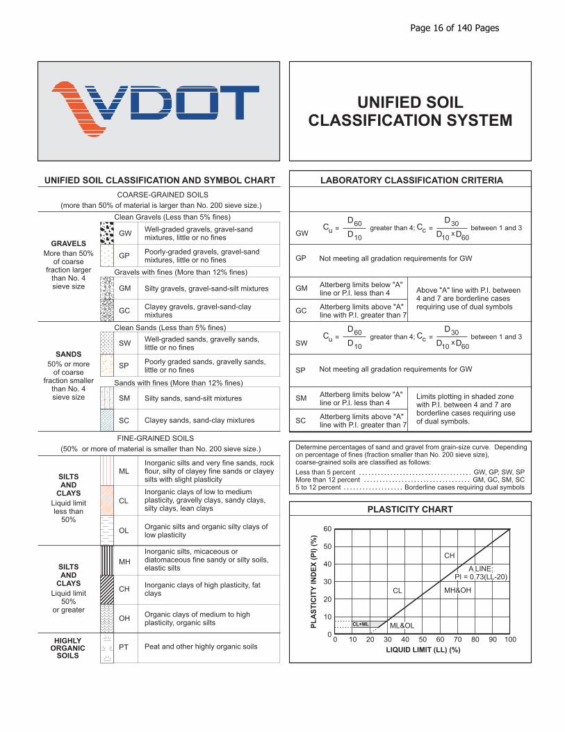
UNIFIED SOIL CLASSIFICATION AND SYMBOL CHART LABORATORY CLASSIFICATION CRITERIA
PLASTICITY CHART
COARSE-GRAINED SOILS
FINE-GRAINED SOILS
(more than 50% of material is larger than No. 200 sieve size.)
(50% or more of material is smaller than No. 200 sieve size.)
Well-graded gravels, gravel-sandmixtures, little or no fines
greater than 4;
greater than 4;
between 1 and 3
between 1 and 3
=
=
=
=
Clean Gravels (Less than 5% fines)
C
C
C
C
D
D
D
D
D
D
D
D
D
D
u
u
c
c
60
60
30
30
x
x
10
10
10
10
60
60
Clean Sands (Less than 5% fines)
Above "A" line with P.I. between4 and 7 are borderline casesrequiring use of dual symbols
Limits plotting in shaded zonewith P.I. between 4 and 7 areborderline cases requiring useof dual symbols.
Determine percentages of sand and gravel from grain-size curve. Dependingon percentage of fines (fraction smaller than No. 200 sieve size),coarse-grained soils are classified as follows:
Less than 5 percentMore than 12 percent5 to 12 percent
GW, GP, SW, SPGM, GC, SM, SC
Borderline cases requiring dual symbols
Gravels with fines (More than 12% fines)
Sands with fines (More than 12% fines)
Well-graded sands, gravelly sands,little or no fines
Silty gravels, gravel-sand-silt mixturesAtterberg limits below "A"line or P.I. less than 4
Atterberg limits below "A"line or P.I. less than 4
Atterberg limits above "A"line with P.I. greater than 7
Atterberg limits above "A"line with P.I. greater than 7
Silty sands, sand-silt mixtures
Inorganic silts and very fine sands, rockflour, silty of clayey fine sands or clayeysilts with slight plasticity
Inorganic clays of low to mediumplasticity, gravelly clays, sandy clays,silty clays, lean clays
Inorganic silts, micaceous ordiatomaceous fine sandy or silty soils,elastic silts
Peat and other highly organic soils
Poorly-graded gravels, gravel-sandmixtures, little or no fines Not meeting all gradation requirements for GW
Not meeting all gradation requirements for GWPoorly graded sands, gravelly sands,little or no fines
Clayey gravels, gravel-sand-claymixtures
Clayey sands, sand-clay mixtures
Inorganic clays of high plasticity, fatclays
Organic silts and organic silty clays oflow plasticity
Organic clays of medium to highplasticity, organic silts
60
50
40
30
20
10
00 10 20 30 40 50
LIQUID LIMIT (LL) (%)
CL
CL+ML
CH
PL
AS
TIC
ITY
IND
EX
(P
I) (
%)
60 70 80 90 100
GW GW
GRAVELS
SANDS
SILTSAND
CLAYS
SILTSAND
CLAYS
HIGHLYORGANIC
SOILS
More than 50%of coarse
fraction largerthan No. 4sieve size
50% or moreof coarse
fraction smallerthan No. 4sieve size
Liquid limitless than
50%
Liquid limit50%
or greater
SW SW
GM GM
SM SM
ML
MH
PT
GP GP
SPSP
GC GC
SC SC
CL
CH
OL
OH
MH&OH
A LINE:PI = 0.73(LL-20)
ML&OL
UNIFIED SOILCLASSIFICATION SYSTEM
Page 16 of 140 Pages

CH -
Fat Clay
CL -
Lean Clay
FL -Fill
GC - Clayey
Gravel
GM - Silty
Gravel
GP - Poorly-
graded Gravel
GW - Well-
Graded Gravel
ML - Silt
SC -
Clayey Sand
CL-ML
GC-GM
SW - Well-
Graded Sand
SM - Silty
Sand
SP - Poorly-
Graded Sand
Pavement/Soils
ASPH-
ASPHALT PVT
CONC-
CONCRETE PVT
GP-GC
GP-GM
GW-GC
GW-GM
SP-SC
SP-SM
SW-SC
SW-SM
AND -
Andesite
BST -
Basalt
CAV -
Cavity
DBS -
Diabase
DRT -
Diorite
GBR -
Gabbro
GGE -
Gouge SPT
Core
Grab
No
Recovery
Other
SLS -
Siltstone
SST-SHL -
Interbedded
Sandstone/Shale
MYL -
Mylonite
PHY -
Phyllite
RHY -
Rhyolite
SCH -
Schist
SedimentaryRocks
MetamorphicRocks
SamplingIgneousRocks
MATERIAL AND SAMPLESYMBOLS LIST
GNS -
Gneiss
Auger
Undisturbed
CGL -
Conglomorate
COL -
Coal
GWK -
Graywacke
LST -
Limestone
SHL -
Shale
SST -
Sandstone
CLST - Cherty
Limestone
SLT -
Slate
GRD -
Granodiorite
GRN
Granite
POR -
Porphyry
SE -
Shell Bed
UCY -
Underclay
SST-SLS -
Interbedded
Sandstone/Siltstone
MH -
Elastic Silt
MH/CH
MH/ML
MH/SM
ML/CL
ML/GM
ML/SM
GM/GP
GM/ML
GM/SM
HWR
Highly Weathered
Rock
MST
Mudstone
BRC -
Breccia
Misc.
SHDS
Shaly Dolostone
CHK
Chalk
SHLS-Shaly
Limestone
MSH
Silty Shale
Page 1of 2
SSHL
Sandy Shale
Vane
Page 17 of 140 Pages

Pavement/SoilsSedimentary
RocksMetamorphic
RocksSampling
IgneousRocks
MATERIAL AND SAMPLESYMBOLS LIST
TOPS-
TOPSOIL CH/CL CH/MH CH/SC
CL/ML CL/SC CL/CHCRA
Crushed Aggregate
GC/SC
GP/GW
GP/SPGW/GP ML/MH
OH
Organic
OH/OL
OL
OrganicOL/OHPT
Peat
SC/CH
SC/CL
SC/GC SC-SM
BLD-Boulder
Bed
CHT
Charnocktite
DLS
Dolostone
LST-DLS-
Interbedded
Limestone/Dolostone
MSLS
Metasiltstone
MSST
Metasandstone
QZT -
Quartzite
MBST
Metabasalt
SPS
Soapstone
MBL
Marble
Page 2 of 2
SP/SW SM/GM SM/MH
SM/ML SM/SC SP/GP SW/SP
Page 18 of 140 Pages

Test Boring Notes 1. Classification of soil is by visual inspection and is in accordance with the Unified Soil Classification
System. 2. Estimated groundwater levels are indicated on the logs. These are only estimates from available data
and may vary with precipitation, porosity of soil, site topography, etc. 3. Sampling data presents standard penetrations for 6-inch intervals or as indicated with graphic
representations adjacent to the sampling data. 4. The logs and related information depict subsurface conditions at the specific locations and at the
particular time when drilled. Soil conditions at other locations may differ from conditions occurring at the test locations. Also, the passage of time may result in a change in the subsurface conditions at the test locations.
5. The stratification lines represent the approximate boundary between soil types as determined in the
sampling operation. Some variation may be expected vertically between samples taken. The soil profile, groundwater level observations and penetration resistances presented on the logs have been made with reasonable care and accuracy and must be considered only an approximate representation of subsurface conditions to be encountered at the particular location.
Page 19 of 140 Pages
23.6
14.2
17.5
24.0
28.9
30.8
26.0
24.9
23.4
29
49
8
19
46.4
79.0
0.0 / 23.0Topsoil = 3 inches TOPS0.25 / 22.75Alluvium, Brown, fine to coarse, SILTY SAND, loose, moistSM2.5 / 20.5Alluvium, Brown, fine to coarse, CLAYEY SAND, loose,moist SC5.0 / 18.0SAME: contains rock fragments below 5.0 ft.
8.5 / 14.5Alluvium, Brown, fine, CLAYEY SAND, very loose, moistSC
13.5 / 9.5Potomac Group, Brown and gray, fine to coarse, SILTYSAND, medium dense, moist SM
18.5 / 4.5Potomac Group, Gray, SILT WITH SAND, very stiff, moistML
23.5 / -0.5Potomac Group, Tan and light brown, fine to coarse,CLAYEY SAND, medium dense, moist SC
33.5 / -10.5SAME: light gray, fine to medium, dense below 33.5 ft.
63
83
67
83
100
83
100
100
100
PAGE 1 OF 2
15BR-01
15BR-01
FIELD DESCRIPTION OF STRATA
GROUND WATER
PAGE 1 OF 2OFFSET: 44.3 ft. RightLONGITUDE: -77.299049° WCOORD. DATUM: NAD 83
REMARKS: Cave-in depth: 16.5 ft.
Copyright 2015, Commonwealth of Virginia
SP
T_L
OG
B:R
OU
TE
1 S
IDE
WA
LK O
VE
R P
OW
ELL
S C
RE
EK
LO
GS
.GP
J:8.
30.0
02:0
2101
1:12
/4/1
5
LAB DATA
MO
IST
UR
E C
ON
TE
NT
(%
)
PLA
ST
ICIT
Y IN
DE
X
PILL
LIQ
UID
LIM
IT
FIN
ES
CO
NT
EN
T -
#200
(%
)
SO
IL R
EC
OV
ER
Y (
%)
CO
RE
RE
CO
VE
RY
(%
)FIRST ENCOUNTERED AT 8.5 ft DEPTH
STABILIZED AT 5.5 ft
DIP °
R O C K
SA
MP
LE L
EG
EN
D
S O I L
PROJECT #:LOCATION:STRUCTURE:
ELE
VA
TIO
N (
ft)
20
15
10
5
0
-5
-10
DE
PT
H (
ft)
SA
MP
LE IN
TE
RV
AL
RO
CK
QU
ALI
TY
DE
SIG
NA
TIO
N
ST
AN
DA
RD
PE
NE
TR
AT
ION
TE
ST
HA
MM
ER
BLO
WS
FIELD DATA
ST
RA
TA
LE
GE
ND
JOIN
TS
ST
RA
TA
2
4
6
8
10
12
14
16
18
20
22
24
26
28
30
32
34
STATION: 16+18LATITUDE: 38.595601° NSURFACE ELEVATION: 23.0 ft
(NFO) EN13-076-158Route 1 SidewalkBRIDGE B-601
Date(s) Drilled: 6/16/2015 - 6/16/2015Drilling Method(s): 3.25" I.D. HSASPT Method: Automatic HammerOther Test(s):Driller: Connelly and Associates, Inc. (R. Wilcher)Logger: A. Mohamed
1
3
3
1
5
4
7
6
6
3
2
1
7
7
11
8
13
4
3
1
8
10
14
12
18
25
7 22.5
4
5
6.5
8.5
10
13.5
15
18.5
20
23.5
25
28.5
30
33.5
Page 20 of 140 Pages
23.7
23.0
25.4
26.0
21.9
67 35 97.7
38.5 / -15.5SAME: medium dense below 38.5 ft.
48.5 / -25.5Potomac Group, Tan, fine to coarse, SILTY SAND,medium dense, moist SM
53.5 / -30.5Potomac Group, Gray and brown, FAT CLAY, hard, moistCH
58.5 / -35.5Potomac Group, Gray, fine to coarse, SILTY SAND, verydense, moist SM60.0 / -37.0BOTTOM OF BORING AT 60.0 FT.
100
100
100
100
100
PAGE 2 OF 2
15BR-01
15BR-01
FIELD DESCRIPTION OF STRATA
GROUND WATER
PAGE 2 OF 2OFFSET: 44.3 ft. RightLONGITUDE: -77.299049° WCOORD. DATUM: NAD 83
REMARKS: Cave-in depth: 16.5 ft.
Copyright 2015, Commonwealth of Virginia
SP
T_L
OG
B:R
OU
TE
1 S
IDE
WA
LK O
VE
R P
OW
ELL
S C
RE
EK
LO
GS
.GP
J:8.
30.0
02:0
2101
1:12
/4/1
5
LAB DATA
MO
IST
UR
E C
ON
TE
NT
(%
)
PLA
ST
ICIT
Y IN
DE
X
PILL
LIQ
UID
LIM
IT
FIN
ES
CO
NT
EN
T -
#200
(%
)
SO
IL R
EC
OV
ER
Y (
%)
CO
RE
RE
CO
VE
RY
(%
)FIRST ENCOUNTERED AT 8.5 ft DEPTH
STABILIZED AT 5.5 ft
DIP °
R O C K
SA
MP
LE L
EG
EN
D
S O I L
PROJECT #:LOCATION:STRUCTURE:
ELE
VA
TIO
N (
ft)
-15
-20
-25
-30
-35
DE
PT
H (
ft)
SA
MP
LE IN
TE
RV
AL
RO
CK
QU
ALI
TY
DE
SIG
NA
TIO
N
ST
AN
DA
RD
PE
NE
TR
AT
ION
TE
ST
HA
MM
ER
BLO
WS
FIELD DATA
ST
RA
TA
LE
GE
ND
JOIN
TS
ST
RA
TA
36
38
40
42
44
46
48
50
52
54
56
58
60
STATION: 16+18LATITUDE: 38.595601° NSURFACE ELEVATION: 23.0 ft
(NFO) EN13-076-158Route 1 SidewalkBRIDGE B-601
Date(s) Drilled: 6/16/2015 - 6/16/2015Drilling Method(s): 3.25" I.D. HSASPT Method: Automatic HammerOther Test(s):Driller: Connelly and Associates, Inc. (R. Wilcher)Logger: A. Mohamed
7
4
5
14
19
9
10
9
20
22
19
14
17
23
32
35
38.5
40
43.5
45
48.5
50
53.5
55
58.5
60
Page 21 of 140 Pages

42.5
29.4
19.1
8.6
31.0
28.9
30.2
30.1
28.7
37.3
25.4
33.5
25.9
25
45
69
3
21
48
6.9
28.1
77.1
0.0 / 22.0Topsoil = 3 inches TOPS0.25 / 21.75Alluvium, Brown, LEAN CLAY, soft, moist CL2.0 / 20.0Alluvium, Brown, FAT CLAY, contains gravel, stiff, moistCH4.0 / 18.0Alluvium, Brown, fine to coarse, CLAYEY SAND, containsgravel, medium dense, moist SC6.0 / 16.0Alluvium, Gray, fine to medium, WELL GRADED GRAVELWITH SAND, medium dense, moist GW-GM8.0 / 14.0Potomac Group, Orange and gray, fine to coarse, SILTYSAND, medium dense, moist SM10.0 / 12.0Potomac Group, Orange and gray, fine to coarse, CLAYEYSAND, medium dense, moist SC12.0 / 10.0SAME: light brown and orange below 12.0 ft.14.0 / 8.0SAME: tan below 14.0 ft.16.0 / 6.0SAME: brown below 16.0 ft.18.0 / 4.0SAME: tan below 18.0 ft.
20.0 / 2.0SAME: light brown below 20.0 ft.
22.0 / 0.0Potomac Group, Gray, FAT CLAY, stiff, moist CH
24.0 / -2.0Potomac Group, Orange and tan, fine and coarse,CLAYEY SAND, medium dense, moist SC26.0 / -4.0BOTTOM OF BORING AT 26.0 FT.
50
63
38
50
75
75
75
75
75
75
75
100
1200
PAGE 1 OF 1
15BR-02
15BR-02
FIELD DESCRIPTION OF STRATA
GROUND WATER
PAGE 1 OF 1OFFSET: 56.7 ft. RightLONGITUDE: -77.298883° WCOORD. DATUM: NAD 83
REMARKS: Cave-in depth: 8.5 ft.
Copyright 2015, Commonwealth of Virginia
SP
T_L
OG
B:R
OU
TE
1 S
IDE
WA
LK O
VE
R P
OW
ELL
S C
RE
EK
LO
GS
.GP
J:8.
30.0
02:0
2101
1:12
/4/1
5
LAB DATA
MO
IST
UR
E C
ON
TE
NT
(%
)
PLA
ST
ICIT
Y IN
DE
X
PILL
LIQ
UID
LIM
IT
FIN
ES
CO
NT
EN
T -
#200
(%
)
SO
IL R
EC
OV
ER
Y (
%)
CO
RE
RE
CO
VE
RY
(%
)FIRST ENCOUNTERED AT 6.0 ft DEPTH
STABILIZED AT 4.5 ft
DIP °
R O C K
SA
MP
LE L
EG
EN
D
S O I L
PROJECT #:LOCATION:STRUCTURE:
ELE
VA
TIO
N (
ft)
20
15
10
5
0
DE
PT
H (
ft)
SA
MP
LE IN
TE
RV
AL
RO
CK
QU
ALI
TY
DE
SIG
NA
TIO
N
ST
AN
DA
RD
PE
NE
TR
AT
ION
TE
ST
HA
MM
ER
BLO
WS
FIELD DATA
ST
RA
TA
LE
GE
ND
JOIN
TS
ST
RA
TA
2
4
6
8
10
12
14
16
18
20
22
24
26
STATION: 17+02LATITUDE: 38.595784° NSURFACE ELEVATION: 22.0 ft
(NFO) EN13-076-158Route 1 SidewalkBRIDGE B-601
Date(s) Drilled: 6/17/2015 - 6/17/2015Drilling Method(s): 3.25" I.D. HSASPT Method: Automatic HammerOther Test(s):Driller: Connelly and Associates, Inc. (R. Wilcher)Logger: A. Mohamed
1
4
1
5
4
7
4
5
11
6
9
6
9
1112
1
5
4
7
5
9
6
5
12
7
6
10
1
4
12
8
6
10
9
7
13
8
9
2
1
1
8
8
8
11
9
8
14
8
10
11
2
4
6
8
10
12
14
16
18
20
22
24
26
Page 22 of 140 Pages
12.3
23.1
27.5
8.2
34.2
28.8
25.4
27.9
23.0
46
34
20
12
31.1
37.9
0.0 / 27.0Topsoil = 3 inches TOPS0.25 / 26.75Alluvium, Brown, fine to coarse, CLAYEY SAND FILL,loose, moist FL2.5 / 24.5SAME: medium dense below 2.5 ft.5.0 / 22.0Alluvium, Brown, fine to coarse, CLAYEY SAND, loose,moist SC
8.5 / 18.5SAME: with gravel, medium dense below 8.5 ft.
13.5 / 13.5Potomac Group, Gray and orange, fine to coarse, CLAYEYSAND, loose, moist SC
18.5 / 8.5Potomac Group, Orange, fine to coarse, CLAYEY SAND,medium dense, moist SC
23.5 / 3.5SAME: tan below 23.5 ft.
28.5 / -1.5Potomac Group, Gray, fine to coarse, CLAYEY SAND,medium dense, moist SC
33.5 / -6.5Tan, fine to coarse, SILTY SAND, dense, moist SM
75
100
83
83
11
100
100
100
100
PAGE 1 OF 2
15BR-03
15BR-03
FIELD DESCRIPTION OF STRATA
GROUND WATER
PAGE 1 OF 2OFFSET: 32.2 ft. RightLONGITUDE: -77.298954° WCOORD. DATUM: NAD 83
REMARKS: Cave-in depth: 8.5 ft.
Copyright 2015, Commonwealth of Virginia
SP
T_L
OG
B:R
OU
TE
1 S
IDE
WA
LK O
VE
R P
OW
ELL
S C
RE
EK
LO
GS
.GP
J:8.
30.0
02:0
2101
1:12
/4/1
5
LAB DATA
MO
IST
UR
E C
ON
TE
NT
(%
)
PLA
ST
ICIT
Y IN
DE
X
PILL
LIQ
UID
LIM
IT
FIN
ES
CO
NT
EN
T -
#200
(%
)
SO
IL R
EC
OV
ER
Y (
%)
CO
RE
RE
CO
VE
RY
(%
)FIRST ENCOUNTERED AT 6.0 ft DEPTH
STABILIZED AT 4.5 ft
DIP °
R O C K
SA
MP
LE L
EG
EN
D
S O I L
PROJECT #:LOCATION:STRUCTURE:
ELE
VA
TIO
N (
ft)
25
20
15
10
5
0
-5
DE
PT
H (
ft)
SA
MP
LE IN
TE
RV
AL
RO
CK
QU
ALI
TY
DE
SIG
NA
TIO
N
ST
AN
DA
RD
PE
NE
TR
AT
ION
TE
ST
HA
MM
ER
BLO
WS
FIELD DATA
ST
RA
TA
LE
GE
ND
JOIN
TS
ST
RA
TA
2
4
6
8
10
12
14
16
18
20
22
24
26
28
30
32
34
STATION: 17+02LATITUDE: 38.595829° NSURFACE ELEVATION: 27.0 ft
(NFO) EN13-076-158Route 1 SidewalkBRIDGE B-601
Date(s) Drilled: 6/17/2015 - 6/17/2015Drilling Method(s): 3.25" I.D. HSASPT Method: Automatic HammerOther Test(s):Driller: Connelly and Associates, Inc. (R. Wilcher)Logger: A. Mohamed
3
4
3
5
5
6
6
7
10
5
2
5
6
9
8
8
13
6
3
6
4
9
12
11
18
33
3 22.5
4
5
6.5
8.5
10
13.5
15
18.5
20
23.5
25
28.5
30
33.5
Page 23 of 140 Pages
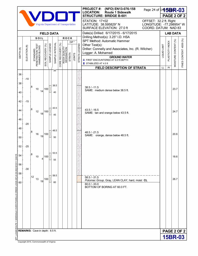
23.7
24.7
20.6
18.6
26.7
38.5 / -11.5SAME: medium dense below 38.5 ft.
43.5 / -16.5SAME: tan and orange below 43.5 ft.
48.5 / -21.5SAME: orange, dense below 48.5 ft.
58.5 / -31.5Potomac Group, Gray, LEAN CLAY, hard, moist CL60.0 / -33.0BOTTOM OF BORING AT 60.0 FT.
100
100
100
100
100
PAGE 2 OF 2
15BR-03
15BR-03
FIELD DESCRIPTION OF STRATA
GROUND WATER
PAGE 2 OF 2OFFSET: 32.2 ft. RightLONGITUDE: -77.298954° WCOORD. DATUM: NAD 83
REMARKS: Cave-in depth: 8.5 ft.
Copyright 2015, Commonwealth of Virginia
SP
T_L
OG
B:R
OU
TE
1 S
IDE
WA
LK O
VE
R P
OW
ELL
S C
RE
EK
LO
GS
.GP
J:8.
30.0
02:0
2101
1:12
/4/1
5
LAB DATA
MO
IST
UR
E C
ON
TE
NT
(%
)
PLA
ST
ICIT
Y IN
DE
X
PILL
LIQ
UID
LIM
IT
FIN
ES
CO
NT
EN
T -
#200
(%
)
SO
IL R
EC
OV
ER
Y (
%)
CO
RE
RE
CO
VE
RY
(%
)FIRST ENCOUNTERED AT 6.0 ft DEPTH
STABILIZED AT 4.5 ft
DIP °
R O C K
SA
MP
LE L
EG
EN
D
S O I L
PROJECT #:LOCATION:STRUCTURE:
ELE
VA
TIO
N (
ft)
-10
-15
-20
-25
-30
DE
PT
H (
ft)
SA
MP
LE IN
TE
RV
AL
RO
CK
QU
ALI
TY
DE
SIG
NA
TIO
N
ST
AN
DA
RD
PE
NE
TR
AT
ION
TE
ST
HA
MM
ER
BLO
WS
FIELD DATA
ST
RA
TA
LE
GE
ND
JOIN
TS
ST
RA
TA
36
38
40
42
44
46
48
50
52
54
56
58
60
STATION: 17+02LATITUDE: 38.595829° NSURFACE ELEVATION: 27.0 ft
(NFO) EN13-076-158Route 1 SidewalkBRIDGE B-601
Date(s) Drilled: 6/17/2015 - 6/17/2015Drilling Method(s): 3.25" I.D. HSASPT Method: Automatic HammerOther Test(s):Driller: Connelly and Associates, Inc. (R. Wilcher)Logger: A. Mohamed
8
6
8
8
12
10
12
16
10
13
14
18
19
4
19
35
38.5
40
43.5
45
48.5
50
53.5
55
58.5
60
Page 24 of 140 Pages
Page 25 of 140 Pages

Appendix B Soil Laboratory Test Results Liquid Limit and Plastic Limit, and Grain Size Analysis Curves (13 pages)
Corrosion Series Test Results (2 pages)
Page 26 of 140 Pages
15BR-02 S-4 6.0-8.0 8.6 - 25 22 3 6.9 GW-GM
07/01/15 TESTED BY: JMK REVIEWED BY: DK PAGE 1 OF 12
15BR-02 S-5 8.0-10.0 31.0 - - - - - -
Jay Kay Testing, Inc. (AASHTO-Accredited)
15BR-02 S-2 2.0-4.0 29.4 - - - - - -
15BR-02 S-3 4.0-6.0 19.1 - - - - - -
15BR-01 S-14 58.5-60.0 21.9 - - - - - -
15BR-02 S-1 0-2.0 42.5 - - - - - -
15BR-01 S-12 48.5-50.0 25.4 - - - - - -
15BR-01 S-13 53.5-55.0 26.0 - 67 32 35 97.7 CH
15BR-01 S-10 38.5-40.0 23.7 - - - - - -
15BR-01 S-11 43.5-45.0 23.0 - - - - - -
15BR-01 S-8 28.5-30.0 24.9 - - - - - -
15BR-01 S-9 33.5-35.0 23.4 - - - - - -
15BR-01 S-6 18.5-20.0 30.8 - 49 30 19 79.0 ML
15BR-01 S-7 23.5-25.0 26.0 - - - - - -
15BR-01 S-4 8.5-10.0 24.0 - 29 21 8 46.4 SC
15BR-01 S-5 13.5-15.0 28.9 - - - - - -
15BR-01 S-2 2.5-4.0 14.2 - - - - - -
15BR-01 S-3 5.0-6.5 17.5 - - - - - -
15SWM-02 S-8 14.0-16.0 25.3 - - - - - -
15BR-01 S-1 0-2.0 23.6 - - - - - -
15SWM-02 S-6 10.0-12.0 26.3 - - - - - -
15SWM-02 S-7 12.0-14.0 27.0 - - - - - -
15SWM-02 S-4 6.0-8.0 11.5 - - - - - -
15SWM-02 S-5 8.0-10.0 31.0 - 69 21 48 44.1 SC
15SWM-02 S-2 2.0-4.0 18.0 - - - - - -
15SWM-02 S-3 4.0-6.0 17.6 - - - - - -
15SWM-01 S-8 14.0-16.0 26.4 - - - - - -
15SWM-02 S-1 0-2.0 17.9 - - - - - -
15SWM-01 S-6 10.0-12.0 24.9 - - - - - -
15SWM-01 S-7 12.0-14.0 26.3 - - - - - -
15SWM-01 S-4 6.0-8.0 10.4 - - - - - -
15SWM-01 S-5 8.0-10.0 28.9 - - - - - -
- - - - -
15SWM-01 S-2 2.0-4.0 18.8 - - - - - -
15SWM-01 S-3 4.0-6.0 21.5 - 25 20 5 26.0 SC-SM
15SWM-01 S-1 0-2.0 27.5 -
SAMPLES: 57 LOCATION: 5233 Lehman Road, Suite 110
Spring Grove, PA 17362
Phone: (410) 259-5101REPORT: 07/01/15 REMARKS:
BORING SAMPLE DEPTH MC % OM % LL PL PI % FINES USCS
-
-
SUMMARY OF LABORATORY TESTING
ROUTE 1 SIDEWALK OVER POWELLS CREEK
PROJECT #: 14156 SAMPLED: - JAY KAY TESTING, INC.
Page 27 of 140 Pages
28.1 -
- - -
-
REMARKS:
S-6 10.0-12.0 28.9
-
ROUTE 1 SIDEWALK OVER POWELLS CREEK
SUMMARY OF LABORATORY TESTING
PROJECT #: 14156 SAMPLED: -
SAMPLE DEPTH MC % OM % LL PL PI
- -
- - - -
BORING % FINES USCS
15BR-02
- -
15BR-02 S-10 18.0-20.0
15BR-02 S-8 14.0-16.0 30.1 -
-
15BR-02
-
-
JAY KAY TESTING, INC.
SAMPLES: LOCATION: 5233 Lehman Road, Suite 110
Spring Grove, PA 17362
Phone: (410) 259-5101REPORT: 07/01/15
57
-
45 24 21 37.3 SC
15BR-02 S-9 16.0-18.0 28.7 - - - - - -
15BR-02 S-7 12.0-14.0 30.2 - - -
S-12 22.0-24.0 33.5 - 69 21 48 77.1 CH
15BR-02 S-11 20.0-22.0 25.4 - - - - -
-
15BR-03 S-1 0-2.0 12.3 - - - - - -
15BR-02 S-13 24.0-26.0 25.9 - - - - -
-
15BR-03 S-3 5.0-6.5 27.5 - - - - - -
15BR-03 S-2 2.5-4.0 23.1 - - - - -
-
15BR-03 S-5 13.5-15.0 34.2 - - - - - -
15BR-03 S-4 8.5-10.0 8.2 - - - - -
SC
15BR-03 S-7 23.5-25.0 25.4 - - - - - -
15BR-03 S-6 18.5-20.0 28.8 - 46 26 20 31.1
SC
15BR-03 S-9 33.5-35.0 23.0 - - - - - -
15BR-03 S-8 28.5-30.0 27.9 - 34 22 12 37.9
-
15BR-03 S-11 43.5-45.0 24.7 - - - - - -
15BR-03 S-10 38.5-40.0 23.7 - - - - -
-
15BR-03 S-13 53.5-55.0 18.6 - - - - - -
15BR-03 S-12 48.5-50.0 20.6 - - - - -
-15BR-03 S-14 58.5-60.0 26.7 - - - - -
Jay Kay Testing, Inc. (AASHTO-Accredited)
07/01/15 TESTED BY: JMK REVIEWED BY: DK PAGE 2 OF 12
Page 28 of 140 Pages
3/8 #60 #100
AASHTO T-89/T-90
ATTERBERG LIMITS CLASSIFICATION
ROUTE 1 SIDEWALK OVER POWELLS CREEK
Boring: 15SWM-01 Project No.: 14156 JAY KAY TESTING, INC.
Sample: S-3 Sampled: - 5233 Lehman Road, Suite 110
Spring Grove, PA 17362
Phone: (410) 259-5101Depth: 4.0-6.0'
GRAIN SIZE (mm) AASHTO T-88
GRAIN SIZE ANALYSIS
Location: -
Diameter U.S. Standard Sieve Hydrometer
GRAVEL SAND SILT OR CLAY
3 3/4 #4 #10 #40 #200
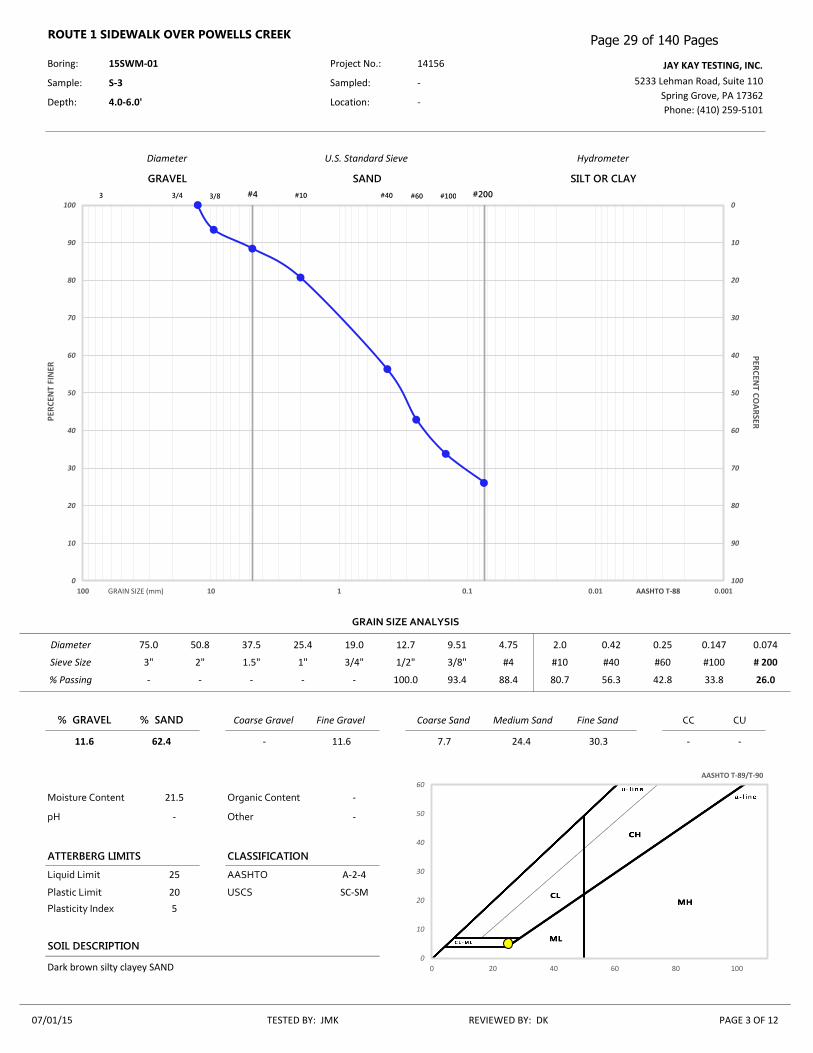
- 100.0 93.4 88.4 80.7 56.3 42.8 33.8 26.0
Diameter 75.0 50.8 37.5 25.4 19.0 12.7 9.51 4.75 2.0 0.42 0.25 0.147 0.074
24.4 30.3 - -
% GRAVEL % SAND Coarse Gravel Fine Gravel Coarse Sand Medium Sand Fine Sand CC CU
Sieve Size 3" 2" 1.5" 1" 3/4" 1/2" 3/8" #4 #10 #40 #60 #100 # 200
% Passing - - - -
Moisture Content 21.5 Organic Content -
pH - Other -
Liquid Limit 25 AASHTO A-2-4
11.6 62.4 - 11.6 7.7
Plastic Limit 20 USCS SC-SM
Plasticity Index 5
SOIL DESCRIPTION
Dark brown silty clayey SAND
07/01/15 TESTED BY: JMK REVIEWED BY: DK PAGE 3 OF 12
0
10
20
30
40
50
60
70
80
90
1000
10
20
30
40
50
60
70
80
90
100
0.0010.010.1110100
PER
CEN
T FI
NER
P
ERC
ENT C
OA
RSER
0
10
20
30
40
50
60
0 20 40 60 80 100
Page 29 of 140 Pages

3/8 #60 #100
AASHTO T-89/T-90
ATTERBERG LIMITS CLASSIFICATION
Sample: S-5 Sampled: - 5233 Lehman Road, Suite 110
Spring Grove, PA 17362
Phone: (410) 259-5101Depth: 8.0-10.0' Location: -
ROUTE 1 SIDEWALK OVER POWELLS CREEK
GRAIN SIZE (mm) AASHTO T-88
Diameter U.S. Standard Sieve Hydrometer
GRAVEL SAND SILT OR CLAY
3 3/4 #4 #10 #40 #200
Boring: 15SWM-02 Project No.: 14156 JAY KAY TESTING, INC.
- - - - 100.0 94.0 72.9 55.1 44.1
GRAIN SIZE ANALYSIS
Diameter 75.0 50.8 37.5 25.4 19.0 12.7 9.51 4.75 2.0 0.42 0.25 0.147 0.074
6.0 49.9 - -
% GRAVEL % SAND Coarse Gravel Fine Gravel Coarse Sand Medium Sand Fine Sand CC CU
Sieve Size 3" 2" 1.5" 1" 3/4" 1/2" 3/8" #4 #10 #40 #60 #100 # 200
% Passing - - - -
Moisture Content 31.0 Organic Content -
pH - Other -
Liquid Limit 69 AASHTO A-7-6
- 55.9 - - -
Plastic Limit 21 USCS SC
Plasticity Index 48
SOIL DESCRIPTION
Brown clayey SAND
07/01/15 TESTED BY: JMK REVIEWED BY: DK PAGE 4 OF 12
0
10
20
30
40
50
60
70
80
90
1000
10
20
30
40
50
60
70
80
90
100
0.0010.010.1110100
PER
CEN
T FI
NER
P
ERC
ENT C
OA
RSER
0
10
20
30
40
50
60
0 20 40 60 80 100
Page 30 of 140 Pages
3/8 #60 #100
AASHTO T-89/T-90
ATTERBERG LIMITS CLASSIFICATION
Sample: S-4 Sampled: - 5233 Lehman Road, Suite 110
Spring Grove, PA 17362
Phone: (410) 259-5101Depth: 8.5-10.0' Location: -
ROUTE 1 SIDEWALK OVER POWELLS CREEK
GRAIN SIZE (mm) AASHTO T-88
Diameter U.S. Standard Sieve Hydrometer
GRAVEL SAND SILT OR CLAY
3 3/4 #4 #10 #40 #200
Boring: 15BR-01 Project No.: 14156 JAY KAY TESTING, INC.
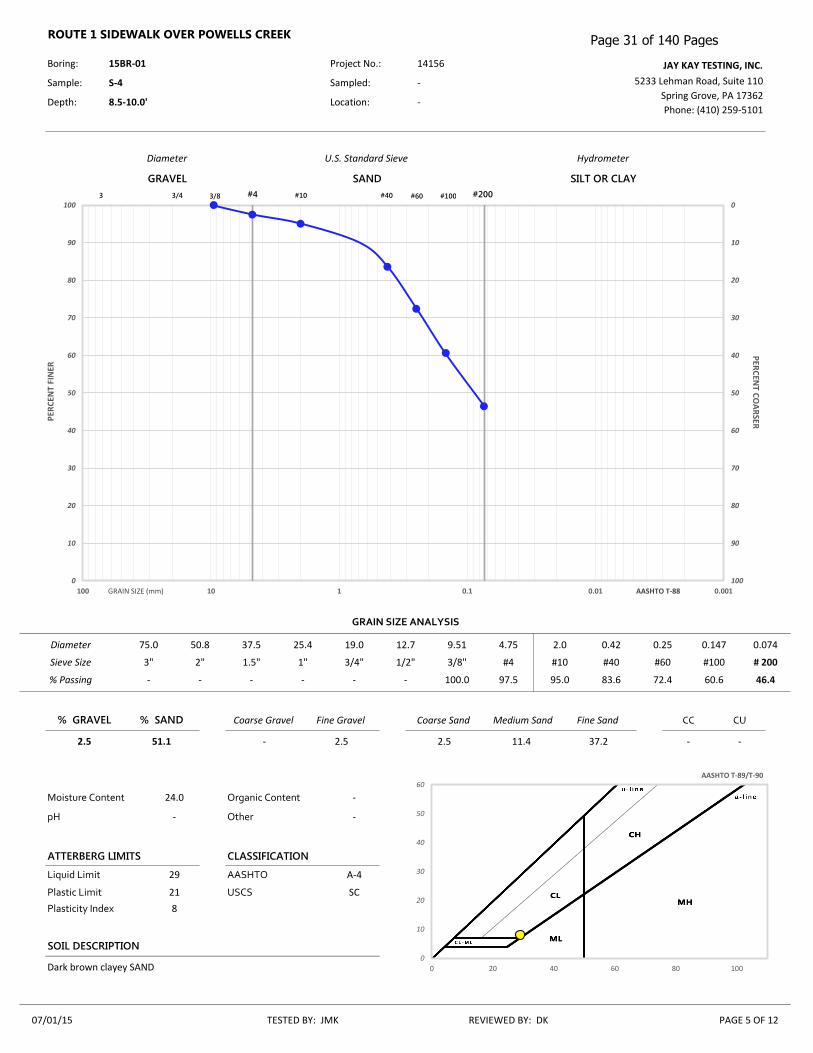
- - 100.0 97.5 95.0 83.6 72.4 60.6 46.4
GRAIN SIZE ANALYSIS
Diameter 75.0 50.8 37.5 25.4 19.0 12.7 9.51 4.75 2.0 0.42 0.25 0.147 0.074
11.4 37.2 - -
% GRAVEL % SAND Coarse Gravel Fine Gravel Coarse Sand Medium Sand Fine Sand CC CU
Sieve Size 3" 2" 1.5" 1" 3/4" 1/2" 3/8" #4 #10 #40 #60 #100 # 200
% Passing - - - -
Moisture Content 24.0 Organic Content -
pH - Other -
Liquid Limit 29 AASHTO A-4
2.5 51.1 - 2.5 2.5
Plastic Limit 21 USCS SC
Plasticity Index 8
SOIL DESCRIPTION
Dark brown clayey SAND
07/01/15 TESTED BY: JMK REVIEWED BY: DK PAGE 5 OF 12
0
10
20
30
40
50
60
70
80
90
1000
10
20
30
40
50
60
70
80
90
100
0.0010.010.1110100
PER
CEN
T FI
NER
P
ERC
ENT C
OA
RSER
0
10
20
30
40
50
60
0 20 40 60 80 100
Page 31 of 140 Pages

3/8 #60 #100
AASHTO T-89/T-90
ATTERBERG LIMITS CLASSIFICATION
Sample: S-6 Sampled: - 5233 Lehman Road, Suite 110
Spring Grove, PA 17362
Phone: (410) 259-5101Depth: 18.5-20.0' Location: -
ROUTE 1 SIDEWALK OVER POWELLS CREEK
GRAIN SIZE (mm) AASHTO T-88
Diameter U.S. Standard Sieve Hydrometer
GRAVEL SAND SILT OR CLAY
3 3/4 #4 #10 #40 #200
Boring: 15BR-01 Project No.: 14156 JAY KAY TESTING, INC.
- - - 100.0 99.6 96.8 93.0 90.3 79.0
GRAIN SIZE ANALYSIS
Diameter 75.0 50.8 37.5 25.4 19.0 12.7 9.51 4.75 2.0 0.42 0.25 0.147 0.074
2.8 17.8 - -
% GRAVEL % SAND Coarse Gravel Fine Gravel Coarse Sand Medium Sand Fine Sand CC CU
Sieve Size 3" 2" 1.5" 1" 3/4" 1/2" 3/8" #4 #10 #40 #60 #100 # 200
% Passing - - - -
Moisture Content 30.8 Organic Content -
pH - Other -
Liquid Limit 49 AASHTO A-7-5
- 21.0 - - 0.4
Plastic Limit 30 USCS ML
Plasticity Index 19
SOIL DESCRIPTION
Gray brown SILT with sand
07/01/15 TESTED BY: JMK REVIEWED BY: DK PAGE 6 OF 12
0
10
20
30
40
50
60
70
80
90
1000
10
20
30
40
50
60
70
80
90
100
0.0010.010.1110100
PER
CEN
T FI
NER
P
ERC
ENT C
OA
RSER
0
10
20
30
40
50
60
0 20 40 60 80 100
Page 32 of 140 Pages
3/8 #60 #100
AASHTO T-89/T-90
ATTERBERG LIMITS CLASSIFICATION
Sample: S-13 Sampled: - 5233 Lehman Road, Suite 110
Spring Grove, PA 17362
Phone: (410) 259-5101Depth: 53.5-55.0' Location: -
ROUTE 1 SIDEWALK OVER POWELLS CREEK
GRAIN SIZE (mm) AASHTO T-88
Diameter U.S. Standard Sieve Hydrometer
GRAVEL SAND SILT OR CLAY
3 3/4 #4 #10 #40 #200
Boring: 15BR-01 Project No.: 14156 JAY KAY TESTING, INC.
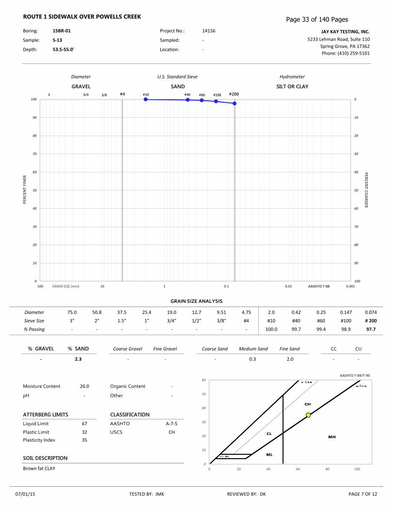
- - - - 100.0 99.7 99.4 98.9 97.7
GRAIN SIZE ANALYSIS
Diameter 75.0 50.8 37.5 25.4 19.0 12.7 9.51 4.75 2.0 0.42 0.25 0.147 0.074
0.3 2.0 - -
% GRAVEL % SAND Coarse Gravel Fine Gravel Coarse Sand Medium Sand Fine Sand CC CU
Sieve Size 3" 2" 1.5" 1" 3/4" 1/2" 3/8" #4 #10 #40 #60 #100 # 200
% Passing - - - -
Moisture Content 26.0 Organic Content -
pH - Other -
Liquid Limit 67 AASHTO A-7-5
- 2.3 - - -
Plastic Limit 32 USCS CH
Plasticity Index 35
SOIL DESCRIPTION
Brown fat CLAY
07/01/15 TESTED BY: JMK REVIEWED BY: DK PAGE 7 OF 12
0
10
20
30
40
50
60
70
80
90
1000
10
20
30
40
50
60
70
80
90
100
0.0010.010.1110100
PER
CEN
T FI
NER
P
ERC
ENT C
OA
RSER
0
10
20
30
40
50
60
0 20 40 60 80 100
Page 33 of 140 Pages

3/8 #60 #100
AASHTO T-89/T-90
ATTERBERG LIMITS CLASSIFICATION
Sample: S-4 Sampled: - 5233 Lehman Road, Suite 110
Spring Grove, PA 17362
Phone: (410) 259-5101Depth: 6.0-8.0' Location: -
ROUTE 1 SIDEWALK OVER POWELLS CREEK
GRAIN SIZE (mm) AASHTO T-88
Diameter U.S. Standard Sieve Hydrometer
GRAVEL SAND SILT OR CLAY
3 3/4 #4 #10 #40 #200
Boring: 15BR-02 Project No.: 14156 JAY KAY TESTING, INC.
86.1 59.4 48.9 37.3 27.7 15.9 11.7 9.3 6.9
GRAIN SIZE ANALYSIS
Diameter 75.0 50.8 37.5 25.4 19.0 12.7 9.51 4.75 2.0 0.42 0.25 0.147 0.074
11.8 9.0 2.89 72.22
% GRAVEL % SAND Coarse Gravel Fine Gravel Coarse Sand Medium Sand Fine Sand CC CU
Sieve Size 3" 2" 1.5" 1" 3/4" 1/2" 3/8" #4 #10 #40 #60 #100 # 200
% Passing - - 100.0 92.5
Moisture Content 8.6 Organic Content -
pH - Other -
Liquid Limit 25 AASHTO A-1-a
62.7 30.4 13.9 48.8 9.6
Plastic Limit 22 USCS GW-GM
Plasticity Index 3
SOIL DESCRIPTION
Dark brown well graded GRAVEL with silt and sand
07/01/15 TESTED BY: JMK REVIEWED BY: DK PAGE 8 OF 12
0
10
20
30
40
50
60
70
80
90
1000
10
20
30
40
50
60
70
80
90
100
0.0010.010.1110100
PER
CEN
T FI
NER
P
ERC
ENT C
OA
RSER
0
10
20
30
40
50
60
0 20 40 60 80 100
Page 34 of 140 Pages

3/8 #60 #100
AASHTO T-89/T-90
ATTERBERG LIMITS CLASSIFICATION
Plastic Limit - USCS -
Plasticity Index -
VISUAL SOIL DESCRIPTION
Light brown clayey sand
10/20/15 TESTED BY: JMK REVIEWED BY: DK PAGE 1 OF 1
Moisture Content - Organic Content -
pH - Other -
Liquid Limit - AASHTO -
- 68.7 - - 0.7 1.5 66.5 - -
% GRAVEL % SAND Coarse Gravel Fine Gravel Coarse Sand Medium Sand Fine Sand CC CU
Sieve Size 3" 2" 1.5" 1" 3/4" 1/2" 3/8" #4 #10 #40 #60 #100 # 200
% Passing - - - - - - - 100.0 99.3 97.8 72.1 39.3 31.3
Diameter 75.0 50.8 37.5 25.4 19.0 12.7 9.51 4.75 2.0 0.42 0.25 0.147 0.074
GRAIN SIZE (mm) AASHTO T-88
GRAIN SIZE ANALYSIS
Location: -
Diameter U.S. Standard Sieve Hydrometer
GRAVEL SAND SILT OR CLAY
3 3/4 #4 #10 #40 #200
ROUTE 1 SIDEWALK OVER POWELLS CREEK
Boring: 15BR-2 Project No.: 14156 JAY KAY TESTING, INC.
Sample: S-6 Sampled: - 5233 Lehman Road, Suite 110
Spring Grove, PA 17362
Phone: (410) 259-5101Depth: 10.5-11.0'
0
10
20
30
40
50
60
70
80
90
1000
10
20
30
40
50
60
70
80
90
100
0.0010.010.1110100
PER
CEN
T FI
NER
P
ERC
ENT C
OA
RSER
0
10
20
30
40
50
60
0 20 40 60 80 100
Page 35 of 140 Pages

3/8 #60 #100
AASHTO T-89/T-90
ATTERBERG LIMITS CLASSIFICATION
Sample: S-10 Sampled: - 5233 Lehman Road, Suite 110
Spring Grove, PA 17362
Phone: (410) 259-5101Depth: 18.0-20.0' Location: -
ROUTE 1 SIDEWALK OVER POWELLS CREEK
GRAIN SIZE (mm) AASHTO T-88
Diameter U.S. Standard Sieve Hydrometer
GRAVEL SAND SILT OR CLAY
3 3/4 #4 #10 #40 #200
Boring: 15BR-02 Project No.: 14156 JAY KAY TESTING, INC.
- - - - 100.0 99.6 87.9 57.2 37.3
GRAIN SIZE ANALYSIS
Diameter 75.0 50.8 37.5 25.4 19.0 12.7 9.51 4.75 2.0 0.42 0.25 0.147 0.074
0.4 62.3 - -
% GRAVEL % SAND Coarse Gravel Fine Gravel Coarse Sand Medium Sand Fine Sand CC CU
Sieve Size 3" 2" 1.5" 1" 3/4" 1/2" 3/8" #4 #10 #40 #60 #100 # 200
% Passing - - - -
Moisture Content 28.1 Organic Content -
pH - Other -
Liquid Limit 45 AASHTO A-7-6
- 62.7 - - -
Plastic Limit 24 USCS SC
Plasticity Index 21
SOIL DESCRIPTION
Light brown clayey SAND
07/01/15 TESTED BY: JMK REVIEWED BY: DK PAGE 9 OF 12
0
10
20
30
40
50
60
70
80
90
1000
10
20
30
40
50
60
70
80
90
100
0.0010.010.1110100
PER
CEN
T FI
NER
P
ERC
ENT C
OA
RSER
0
10
20
30
40
50
60
0 20 40 60 80 100
Page 36 of 140 Pages

3/8 #60 #100
AASHTO T-89/T-90
ATTERBERG LIMITS CLASSIFICATION
Sample: S-12 Sampled: - 5233 Lehman Road, Suite 110
Spring Grove, PA 17362
Phone: (410) 259-5101Depth: 22.0-24.0' Location: -
ROUTE 1 SIDEWALK OVER POWELLS CREEK
Diameter U.S. Standard Sieve Hydrometer
GRAVEL SAND SILT OR CLAY
3 3/4 #4 #10 #40 #200
Boring: 15BR-02 Project No.: 14156 JAY KAY TESTING, INC.
GRAIN SIZE ANALYSIS
Diameter 75.0 50.8 37.5 25.4 19.0 12.7 9.51 4.75 2.0 0.42 0.25 0.147 0.074
GRAIN SIZE (mm) AASHTO T-88
Sieve Size 3" 2" 1.5" 1" 3/4" 1/2" 3/8" #4 #10 #40 #60 #100 # 200
% Passing - - - - - - - - 100.0 93.6 87.9 83.0 77.1
- 22.9 - - - 6.4 16.5 - -
% GRAVEL % SAND Coarse Gravel Fine Gravel Coarse Sand Medium Sand Fine Sand CC CU
Plastic Limit 21 USCS CH
Plasticity Index 48
SOIL DESCRIPTION
Gray fat CLAY with sand
07/01/15 TESTED BY: JMK REVIEWED BY: DK PAGE 10 OF 12
Moisture Content 33.5 Organic Content -
pH - Other -
Liquid Limit 69 AASHTO A-7-6
0
10
20
30
40
50
60
70
80
90
1000
10
20
30
40
50
60
70
80
90
100
0.0010.010.1110100
PER
CEN
T FI
NER
P
ERC
ENT C
OA
RSER
0
10
20
30
40
50
60
0 20 40 60 80 100
Page 37 of 140 Pages

3/8 #60 #100
AASHTO T-89/T-90
ATTERBERG LIMITS CLASSIFICATION
Plastic Limit 26 USCS SC
Plasticity Index 20
SOIL DESCRIPTION
Light brown clayey SAND
07/01/15 TESTED BY: JMK REVIEWED BY: DK PAGE 11 OF 12
Moisture Content 28.8 Organic Content -
pH - Other -
Liquid Limit 46 AASHTO A-2-7
- 68.9 - - - 1.5 67.4 - -
% GRAVEL % SAND Coarse Gravel Fine Gravel Coarse Sand Medium Sand Fine Sand CC CU
Sieve Size 3" 2" 1.5" 1" 3/4" 1/2" 3/8" #4 #10 #40 #60 #100 # 200
% Passing - - - - - - - - 100.0 98.5 75.5 39.1 31.1
GRAIN SIZE ANALYSIS
Diameter 75.0 50.8 37.5 25.4 19.0 12.7 9.51 4.75 2.0 0.42 0.25 0.147 0.074
GRAIN SIZE (mm) AASHTO T-88
Diameter U.S. Standard Sieve Hydrometer
GRAVEL SAND SILT OR CLAY
3 3/4 #4 #10 #40 #200
Boring: 15BR-03 Project No.: 14156 JAY KAY TESTING, INC.
Sample: S-6 Sampled: - 5233 Lehman Road, Suite 110
Spring Grove, PA 17362
Phone: (410) 259-5101Depth: 18.5-20.0' Location: -
ROUTE 1 SIDEWALK OVER POWELLS CREEK
0
10
20
30
40
50
60
70
80
90
1000
10
20
30
40
50
60
70
80
90
100
0.0010.010.1110100
PER
CEN
T FI
NER
P
ERC
ENT C
OA
RSER
0
10
20
30
40
50
60
0 20 40 60 80 100
Page 38 of 140 Pages

3/8 #60 #100
AASHTO T-89/T-90
ATTERBERG LIMITS CLASSIFICATION
Plastic Limit 22 USCS SC
Plasticity Index 12
SOIL DESCRIPTION
Gray clayey SAND
07/01/15 TESTED BY: JMK REVIEWED BY: DK PAGE 12 OF 12
Moisture Content 27.9 Organic Content -
pH - Other -
Liquid Limit 34 AASHTO A-6
- 62.1 - - 0.1 2.8 59.2 - -
% GRAVEL % SAND Coarse Gravel Fine Gravel Coarse Sand Medium Sand Fine Sand CC CU
Sieve Size 3" 2" 1.5" 1" 3/4" 1/2" 3/8" #4 #10 #40 #60 #100 # 200
% Passing - - - - - - - 100.0 99.9 97.1 75.3 47.6 37.9
GRAIN SIZE ANALYSIS
Diameter 75.0 50.8 37.5 25.4 19.0 12.7 9.51 4.75 2.0 0.42 0.25 0.147 0.074
GRAIN SIZE (mm) AASHTO T-88
Diameter U.S. Standard Sieve Hydrometer
GRAVEL SAND SILT OR CLAY
3 3/4 #4 #10 #40 #200
Boring: 15BR-03 Project No.: 14156 JAY KAY TESTING, INC.
Sample: S-8 Sampled: - 5233 Lehman Road, Suite 110
Spring Grove, PA 17362
Phone: (410) 259-5101Depth: 28.5-30.0' Location: -
ROUTE 1 SIDEWALK OVER POWELLS CREEK
0
10
20
30
40
50
60
70
80
90
1000
10
20
30
40
50
60
70
80
90
100
0.0010.010.1110100
PER
CEN
T FI
NER
P
ERC
ENT C
OA
RSER
0
10
20
30
40
50
60
0 20 40 60 80 100
Page 39 of 140 Pages
HP ENVIRONMENTAL
INCORPORATED
Page 1 of 2Report Number: 153909
GeoConcepts Engineering, Inc. Date Received: 07/01/15Attn: Deniz Karadeniz Date Reported: 07/02/1519955 Highland Vista Dr. Project Location: Powell's Creek & Route 1Suite 170Ashburn, VA 20147
1. Client Sample No: 15BR-01 HPE Sample No.: 153909-01Sample Matrix: Soil Date Collected: 06/16/15Sample Location: 0 - 6.5 ft
Test(s) Requested: Soil Corrosion Potential ProfileAnalysis Method(s): Various Date Analyzed: 07/01/15
Analyte Result Units Reporting Limit QualifierResistivity - ASTM G187 5700 ohm-cm N/ARedox Potential - Electrode + 315 mV N/ApH - CA643 4.9 pH N/AChloride (Water Soluble) - CA422 15 mg/Kg 2.5Sulfate (Water Soluble) - CA417 150 mg/Kg 5.0Sulfide (Water Soluble) EPA 376.2 < 1.2 mg/Kg 1.2 UMoisture (Percent) 16 % N/A
2. Client Sample No: 15BR-03 HPE Sample No.: 153909-02Sample Matrix: Soil Date Collected: 06/17/15Sample Location: 2.5 - 6.5 ft
Test(s) Requested: Soil Corrosion Potential ProfileAnalysis Method(s): Various Date Analyzed: 07/01/15
Analyte Result Units Reporting Limit QualifierResistivity - ASTM G187 860 ohm-cm N/ARedox Potential - Electrode + 260 mV N/ApH - CA643 7.2 pH N/AChloride (Water Soluble) - CA422 29 mg/Kg 2.5Sulfate (Water Soluble) - CA417 91 mg/Kg 5.0Sulfide (Water Soluble) EPA 376.2 < 1.2 mg/Kg 1.2 UMoisture (Percent) 21 % N/A
JP 07/02/15
Analyte Qualifier Codes
U = Analyte was not detected
Certificate of Laboratory Analysis
Approved by Date
Page 40 of 140 Pages
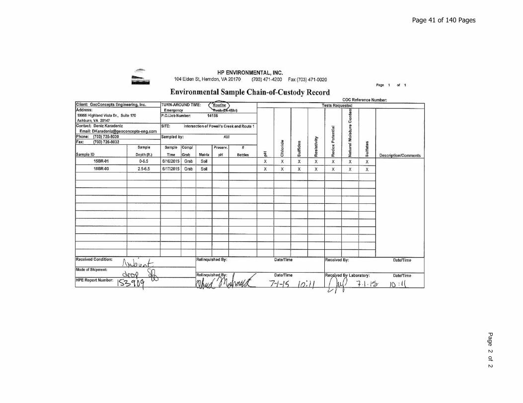
Page 2 of 2
Page 41 of 140 Pages
Appendix C Engineering Analysis Drilled Shaft Axial Compressional Resistance Results (11 pages)
Drilled Shaft Lateral Analysis Results (77 pages)
Page 42 of 140 Pages

LRFD Total Resistance (tons)D
epth
(ft
)
0 20 40 60 80 100 120 140 160 180 2000
510
1520
2530
3540
4550
5560
Dia=4 ft
LRFD Total Resistance (tons)D
epth
(ft
)
0 20 40 60 80 100 120 140 160 180 2000
510
1520
2530
3540
4550
550 Dia=4 ft
Page 43 of 140 Pages
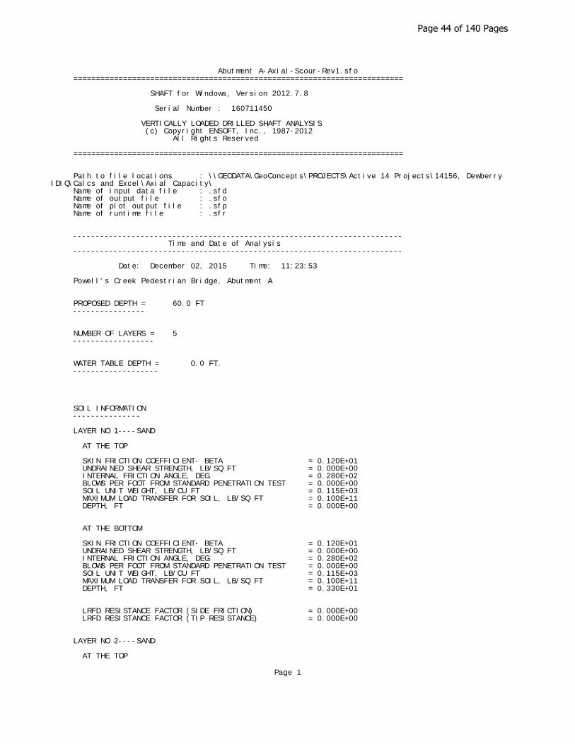
Abutment A-Axial-Scour-Rev1.sfo =========================================================================
SHAFT for Windows, Version 2012.7.8
Serial Number : 160711450
VERTICALLY LOADED DRILLED SHAFT ANALYSIS (c) Copyright ENSOFT, Inc., 1987-2012 All Rights Reserved
=========================================================================
Path to file locations : \\GEODATA\GeoConcepts\PROJECTS\Active 14 Projects\14156, Dewberry IDIQ\Calcs and Excel\Axial Capacity\ Name of input data file : .sfd Name of output file : .sfo Name of plot output file : .sfp Name of runtime file : .sfr
------------------------------------------------------------------------- Time and Date of Analysis -------------------------------------------------------------------------
Date: December 02, 2015 Time: 11:23:53 Powell's Creek Pedestrian Bridge, Abutment A
PROPOSED DEPTH = 60.0 FT ----------------
NUMBER OF LAYERS = 5 ------------------
WATER TABLE DEPTH = 0.0 FT. -------------------
SOIL INFORMATION ---------------
LAYER NO 1----SAND
AT THE TOP
SKIN FRICTION COEFFICIENT- BETA = 0.120E+01 UNDRAINED SHEAR STRENGTH, LB/SQ FT = 0.000E+00 INTERNAL FRICTION ANGLE, DEG. = 0.280E+02 BLOWS PER FOOT FROM STANDARD PENETRATION TEST = 0.000E+00 SOIL UNIT WEIGHT, LB/CU FT = 0.115E+03 MAXIMUM LOAD TRANSFER FOR SOIL, LB/SQ FT = 0.100E+11 DEPTH, FT = 0.000E+00
AT THE BOTTOM
SKIN FRICTION COEFFICIENT- BETA = 0.120E+01 UNDRAINED SHEAR STRENGTH, LB/SQ FT = 0.000E+00 INTERNAL FRICTION ANGLE, DEG. = 0.280E+02 BLOWS PER FOOT FROM STANDARD PENETRATION TEST = 0.000E+00 SOIL UNIT WEIGHT, LB/CU FT = 0.115E+03 MAXIMUM LOAD TRANSFER FOR SOIL, LB/SQ FT = 0.100E+11 DEPTH, FT = 0.330E+01
LRFD RESISTANCE FACTOR (SIDE FRICTION) = 0.000E+00 LRFD RESISTANCE FACTOR (TIP RESISTANCE) = 0.000E+00
LAYER NO 2----SAND
AT THE TOP
Page 1
Page 44 of 140 Pages
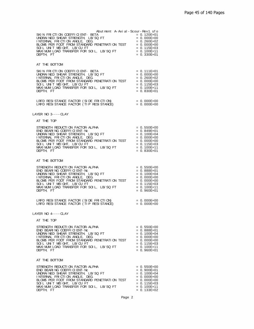
Abutment A-Axial-Scour-Rev1.sfo SKIN FRICTION COEFFICIENT- BETA = 0.120E+01 UNDRAINED SHEAR STRENGTH, LB/SQ FT = 0.000E+00 INTERNAL FRICTION ANGLE, DEG. = 0.260E+02 BLOWS PER FOOT FROM STANDARD PENETRATION TEST = 0.000E+00 SOIL UNIT WEIGHT, LB/CU FT = 0.115E+03 MAXIMUM LOAD TRANSFER FOR SOIL, LB/SQ FT = 0.100E+11 DEPTH, FT = 0.330E+01
AT THE BOTTOM
SKIN FRICTION COEFFICIENT- BETA = 0.111E+01 UNDRAINED SHEAR STRENGTH, LB/SQ FT = 0.000E+00 INTERNAL FRICTION ANGLE, DEG. = 0.260E+02 BLOWS PER FOOT FROM STANDARD PENETRATION TEST = 0.000E+00 SOIL UNIT WEIGHT, LB/CU FT = 0.115E+03 MAXIMUM LOAD TRANSFER FOR SOIL, LB/SQ FT = 0.100E+11 DEPTH, FT = 0.830E+01
LRFD RESISTANCE FACTOR (SIDE FRICTION) = 0.000E+00 LRFD RESISTANCE FACTOR (TIP RESISTANCE) = 0.000E+00
LAYER NO 3----CLAY
AT THE TOP
STRENGTH REDUCTION FACTOR-ALPHA = 0.550E+00 END BEARING COEFFICIENT-Nc = 0.849E+01 UNDRAINED SHEAR STRENGTH, LB/SQ FT = 0.100E+04 INTERNAL FRICTION ANGLE, DEG. = 0.000E+00 BLOWS PER FOOT FROM STANDARD PENETRATION TEST = 0.000E+00 SOIL UNIT WEIGHT, LB/CU FT = 0.115E+03 MAXIMUM LOAD TRANSFER FOR SOIL, LB/SQ FT = 0.100E+11 DEPTH, FT = 0.830E+01
AT THE BOTTOM
STRENGTH REDUCTION FACTOR-ALPHA = 0.550E+00 END BEARING COEFFICIENT-Nc = 0.888E+01 UNDRAINED SHEAR STRENGTH, LB/SQ FT = 0.100E+04 INTERNAL FRICTION ANGLE, DEG. = 0.000E+00 BLOWS PER FOOT FROM STANDARD PENETRATION TEST = 0.000E+00 SOIL UNIT WEIGHT, LB/CU FT = 0.115E+03 MAXIMUM LOAD TRANSFER FOR SOIL, LB/SQ FT = 0.100E+11 DEPTH, FT = 0.960E+01
LRFD RESISTANCE FACTOR (SIDE FRICTION) = 0.000E+00 LRFD RESISTANCE FACTOR (TIP RESISTANCE) = 0.000E+00
LAYER NO 4----CLAY
AT THE TOP
STRENGTH REDUCTION FACTOR-ALPHA = 0.550E+00 END BEARING COEFFICIENT-Nc = 0.888E+01 UNDRAINED SHEAR STRENGTH, LB/SQ FT = 0.100E+04 INTERNAL FRICTION ANGLE, DEG. = 0.000E+00 BLOWS PER FOOT FROM STANDARD PENETRATION TEST = 0.000E+00 SOIL UNIT WEIGHT, LB/CU FT = 0.115E+03 MAXIMUM LOAD TRANSFER FOR SOIL, LB/SQ FT = 0.100E+11 DEPTH, FT = 0.960E+01
AT THE BOTTOM
STRENGTH REDUCTION FACTOR-ALPHA = 0.550E+00 END BEARING COEFFICIENT-Nc = 0.900E+01 UNDRAINED SHEAR STRENGTH, LB/SQ FT = 0.100E+04 INTERNAL FRICTION ANGLE, DEG. = 0.000E+00 BLOWS PER FOOT FROM STANDARD PENETRATION TEST = 0.000E+00 SOIL UNIT WEIGHT, LB/CU FT = 0.115E+03 MAXIMUM LOAD TRANSFER FOR SOIL, LB/SQ FT = 0.100E+11 DEPTH, FT = 0.133E+02
Page 2
Page 45 of 140 Pages
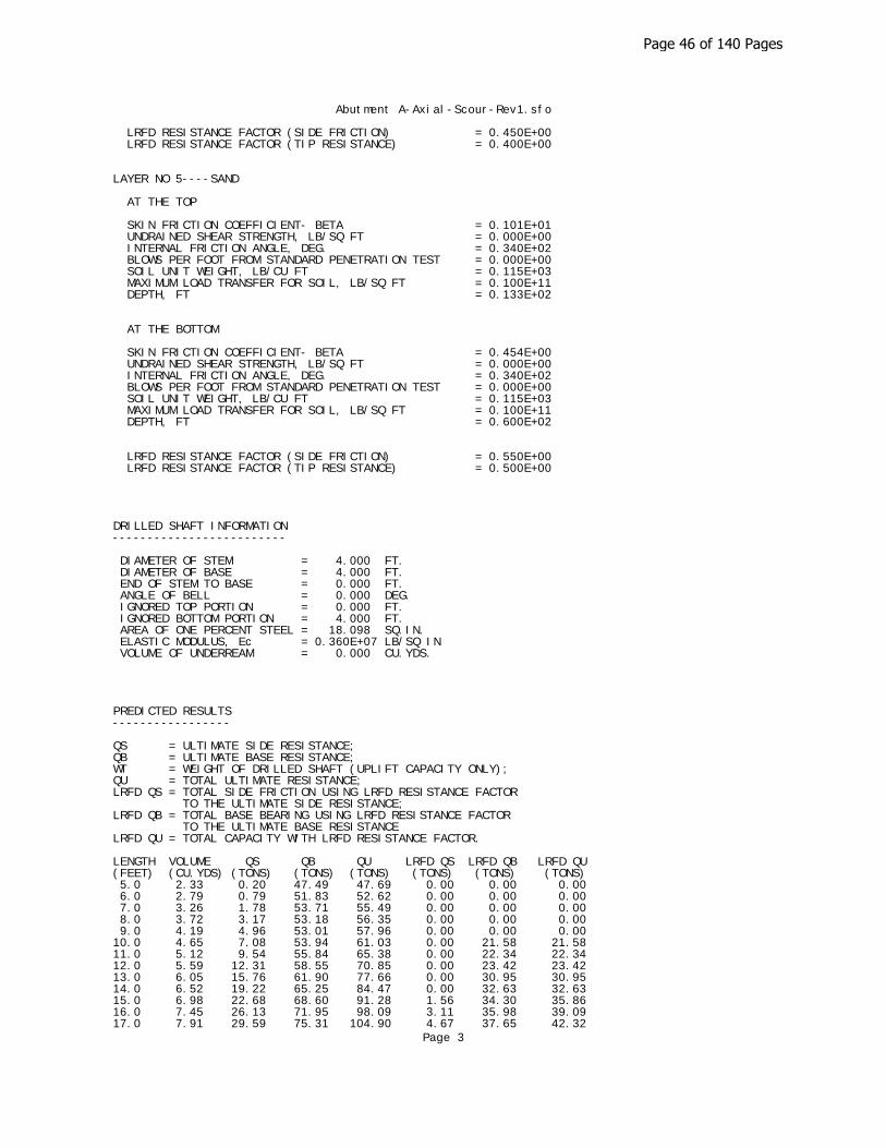
Abutment A-Axial-Scour-Rev1.sfo
LRFD RESISTANCE FACTOR (SIDE FRICTION) = 0.450E+00 LRFD RESISTANCE FACTOR (TIP RESISTANCE) = 0.400E+00
LAYER NO 5----SAND
AT THE TOP
SKIN FRICTION COEFFICIENT- BETA = 0.101E+01 UNDRAINED SHEAR STRENGTH, LB/SQ FT = 0.000E+00 INTERNAL FRICTION ANGLE, DEG. = 0.340E+02 BLOWS PER FOOT FROM STANDARD PENETRATION TEST = 0.000E+00 SOIL UNIT WEIGHT, LB/CU FT = 0.115E+03 MAXIMUM LOAD TRANSFER FOR SOIL, LB/SQ FT = 0.100E+11 DEPTH, FT = 0.133E+02
AT THE BOTTOM
SKIN FRICTION COEFFICIENT- BETA = 0.454E+00 UNDRAINED SHEAR STRENGTH, LB/SQ FT = 0.000E+00 INTERNAL FRICTION ANGLE, DEG. = 0.340E+02 BLOWS PER FOOT FROM STANDARD PENETRATION TEST = 0.000E+00 SOIL UNIT WEIGHT, LB/CU FT = 0.115E+03 MAXIMUM LOAD TRANSFER FOR SOIL, LB/SQ FT = 0.100E+11 DEPTH, FT = 0.600E+02
LRFD RESISTANCE FACTOR (SIDE FRICTION) = 0.550E+00 LRFD RESISTANCE FACTOR (TIP RESISTANCE) = 0.500E+00
DRILLED SHAFT INFORMATION -------------------------
DIAMETER OF STEM = 4.000 FT. DIAMETER OF BASE = 4.000 FT. END OF STEM TO BASE = 0.000 FT. ANGLE OF BELL = 0.000 DEG. IGNORED TOP PORTION = 0.000 FT. IGNORED BOTTOM PORTION = 4.000 FT. AREA OF ONE PERCENT STEEL = 18.098 SQ.IN. ELASTIC MODULUS, Ec = 0.360E+07 LB/SQ IN VOLUME OF UNDERREAM = 0.000 CU.YDS.
PREDICTED RESULTS -----------------
QS = ULTIMATE SIDE RESISTANCE; QB = ULTIMATE BASE RESISTANCE; WT = WEIGHT OF DRILLED SHAFT (UPLIFT CAPACITY ONLY); QU = TOTAL ULTIMATE RESISTANCE; LRFD QS = TOTAL SIDE FRICTION USING LRFD RESISTANCE FACTOR TO THE ULTIMATE SIDE RESISTANCE; LRFD QB = TOTAL BASE BEARING USING LRFD RESISTANCE FACTOR TO THE ULTIMATE BASE RESISTANCE LRFD QU = TOTAL CAPACITY WITH LRFD RESISTANCE FACTOR.
LENGTH VOLUME QS QB QU LRFD QS LRFD QB LRFD QU (FEET) (CU.YDS) (TONS) (TONS) (TONS) (TONS) (TONS) (TONS) 5.0 2.33 0.20 47.49 47.69 0.00 0.00 0.00 6.0 2.79 0.79 51.83 52.62 0.00 0.00 0.00 7.0 3.26 1.78 53.71 55.49 0.00 0.00 0.00 8.0 3.72 3.17 53.18 56.35 0.00 0.00 0.00 9.0 4.19 4.96 53.01 57.96 0.00 0.00 0.00 10.0 4.65 7.08 53.94 61.03 0.00 21.58 21.58 11.0 5.12 9.54 55.84 65.38 0.00 22.34 22.34 12.0 5.59 12.31 58.55 70.85 0.00 23.42 23.42 13.0 6.05 15.76 61.90 77.66 0.00 30.95 30.95 14.0 6.52 19.22 65.25 84.47 0.00 32.63 32.63 15.0 6.98 22.68 68.60 91.28 1.56 34.30 35.86 16.0 7.45 26.13 71.95 98.09 3.11 35.98 39.09 17.0 7.91 29.59 75.31 104.90 4.67 37.65 42.32
Page 3
Page 46 of 140 Pages
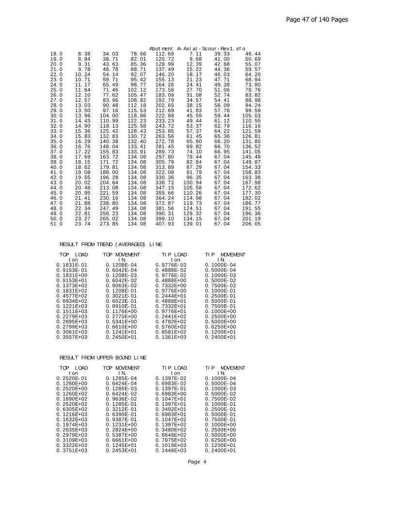
Abutment A-Axial-Scour-Rev1.sfo 18.0 8.38 34.03 78.66 112.69 7.11 39.33 46.44 19.0 8.84 38.71 82.01 120.72 9.68 41.00 50.69 20.0 9.31 43.63 85.36 128.99 12.39 42.68 55.07 21.0 9.78 48.78 88.71 137.49 15.22 44.36 59.57 22.0 10.24 54.14 92.07 146.20 18.17 46.03 64.20 23.0 10.71 59.71 95.42 155.13 21.23 47.71 68.94 24.0 11.17 65.49 98.77 164.26 24.41 49.38 73.80 25.0 11.64 71.46 102.12 173.58 27.70 51.06 78.76 26.0 12.10 77.62 105.47 183.09 31.08 52.74 83.82 27.0 12.57 83.96 108.82 192.79 34.57 54.41 88.98 28.0 13.03 90.48 112.18 202.65 38.15 56.09 94.24 29.0 13.50 97.16 115.53 212.69 41.83 57.76 99.59 30.0 13.96 104.00 118.88 222.88 45.59 59.44 105.03 31.0 14.43 110.99 122.23 233.23 49.44 61.12 110.55 32.0 14.90 118.13 125.58 243.72 53.37 62.79 116.16 33.0 15.36 125.42 128.43 253.85 57.37 64.22 121.59 34.0 15.83 132.83 130.72 263.56 61.45 65.36 126.81 35.0 16.29 140.38 132.40 272.78 65.60 66.20 131.80 36.0 16.76 148.04 133.41 281.45 69.82 66.70 136.52 37.0 17.22 155.83 133.91 289.73 74.10 66.95 141.05 38.0 17.69 163.72 134.08 297.80 78.44 67.04 145.48 39.0 18.15 171.72 134.08 305.79 82.84 67.04 149.87 40.0 18.62 179.81 134.08 313.89 87.29 67.04 154.33 41.0 19.08 188.00 134.08 322.08 91.79 67.04 158.83 42.0 19.55 196.28 134.08 330.36 96.35 67.04 163.38 43.0 20.02 204.64 134.08 338.72 100.94 67.04 167.98 44.0 20.48 213.08 134.08 347.15 105.58 67.04 172.62 45.0 20.95 221.59 134.08 355.66 110.26 67.04 177.30 46.0 21.41 230.16 134.08 364.24 114.98 67.04 182.02 47.0 21.88 238.80 134.08 372.87 119.73 67.04 186.77 48.0 22.34 247.49 134.08 381.56 124.51 67.04 191.55 49.0 22.81 256.23 134.08 390.31 129.32 67.04 196.36 50.0 23.27 265.02 134.08 399.10 134.15 67.04 201.19 51.0 23.74 273.85 134.08 407.93 139.01 67.04 206.05
RESULT FROM TREND (AVERAGED) LINE
TOP LOAD TOP MOVEMENT TIP LOAD TIP MOVEMENT ton IN. ton IN. 0.1831E-01 0.1208E-04 0.9776E-03 0.1000E-04 0.9153E-01 0.6042E-04 0.4888E-02 0.5000E-04 0.1831E+00 0.1208E-03 0.9776E-02 0.1000E-03 0.9153E+01 0.6042E-02 0.4888E+00 0.5000E-02 0.1373E+02 0.9063E-02 0.7332E+00 0.7500E-02 0.1831E+02 0.1208E-01 0.9776E+00 0.1000E-01 0.4577E+02 0.3021E-01 0.2444E+01 0.2500E-01 0.8934E+02 0.6023E-01 0.4888E+01 0.5000E-01 0.1221E+03 0.8910E-01 0.7332E+01 0.7500E-01 0.1511E+03 0.1176E+00 0.9776E+01 0.1000E+00 0.2279E+03 0.2775E+00 0.2441E+02 0.2500E+00 0.2695E+03 0.5341E+00 0.4782E+02 0.5000E+00 0.2799E+03 0.6610E+00 0.5760E+02 0.6250E+00 0.3061E+03 0.1241E+01 0.8581E+02 0.1200E+01 0.3557E+03 0.2450E+01 0.1361E+03 0.2400E+01
RESULT FROM UPPER-BOUND LINE
TOP LOAD TOP MOVEMENT TIP LOAD TIP MOVEMENT ton IN. ton IN. 0.2520E-01 0.1285E-04 0.1397E-02 0.1000E-04 0.1260E+00 0.6424E-04 0.6983E-02 0.5000E-04 0.2520E+00 0.1285E-03 0.1397E-01 0.1000E-03 0.1260E+02 0.6424E-02 0.6983E+00 0.5000E-02 0.1890E+02 0.9636E-02 0.1047E+01 0.7500E-02 0.2520E+02 0.1285E-01 0.1397E+01 0.1000E-01 0.6305E+02 0.3212E-01 0.3492E+01 0.2500E-01 0.1216E+03 0.6390E-01 0.6983E+01 0.5000E-01 0.1632E+03 0.9387E-01 0.1047E+02 0.7500E-01 0.1974E+03 0.1231E+00 0.1397E+02 0.1000E+00 0.2635E+03 0.2824E+00 0.3480E+02 0.2500E+00 0.2979E+03 0.5387E+00 0.6648E+02 0.5000E+00 0.3109E+03 0.6661E+00 0.7975E+02 0.6250E+00 0.3322E+03 0.1245E+01 0.1019E+03 0.1200E+01 0.3751E+03 0.2453E+01 0.1448E+03 0.2400E+01
Page 4
Page 47 of 140 Pages

Abutment A-Axial-Scour-Rev1.sfo
RESULT FROM LOWER-BOUND LINE
TOP LOAD TOP MOVEMENT TIP LOAD TIP MOVEMENT ton IN. ton IN. 0.1164E-01 0.1133E-04 0.5586E-03 0.1000E-04 0.5820E-01 0.5667E-04 0.2793E-02 0.5000E-04 0.1164E+00 0.1133E-03 0.5586E-02 0.1000E-03 0.5820E+01 0.5667E-02 0.2793E+00 0.5000E-02 0.8730E+01 0.8501E-02 0.4190E+00 0.7500E-02 0.1164E+02 0.1133E-01 0.5586E+00 0.1000E-01 0.2910E+02 0.2834E-01 0.1397E+01 0.2500E-01 0.5753E+02 0.5661E-01 0.2793E+01 0.5000E-01 0.8148E+02 0.8438E-01 0.4190E+01 0.7500E-01 0.1041E+03 0.1120E+00 0.5586E+01 0.1000E+00 0.1919E+03 0.2726E+00 0.1402E+02 0.2500E+00 0.2410E+03 0.5295E+00 0.2916E+02 0.5000E+00 0.2487E+03 0.6559E+00 0.3545E+02 0.6250E+00 0.2799E+03 0.1237E+01 0.6972E+02 0.1200E+01 0.3363E+03 0.2448E+01 0.1274E+03 0.2400E+01
Page 5
Page 48 of 140 Pages

LRFD Total Resistance (tons)D
epth
(ft
)
0 20 40 60 80 100 120 140 160 180 2000
510
1520
2530
3540
4550
5560
Dia=4 ft
Page 49 of 140 Pages

Abutment B-Axial-Scour.sfo =========================================================================
SHAFT for Windows, Version 2012.7.8
Serial Number : 160711450
VERTICALLY LOADED DRILLED SHAFT ANALYSIS (c) Copyright ENSOFT, Inc., 1987-2012 All Rights Reserved
=========================================================================
Path to file locations : \\GEODATA\GeoConcepts\PROJECTS\Active 14 Projects\14156, Dewberry IDIQ\Calcs and Excel\Axial Capacity\ Name of input data file : .sfd Name of output file : .sfo Name of plot output file : .sfp Name of runtime file : .sfr
------------------------------------------------------------------------- Time and Date of Analysis -------------------------------------------------------------------------
Date: December 02, 2015 Time: 11:25:01 Powell's Creek Pedestrian Bridge, Abutment B
PROPOSED DEPTH = 60.0 FT ----------------
NUMBER OF LAYERS = 4 ------------------
WATER TABLE DEPTH = 0.0 FT. -------------------
SOIL INFORMATION ---------------
LAYER NO 1----SAND
AT THE TOP
SKIN FRICTION COEFFICIENT- BETA = 0.120E+01 UNDRAINED SHEAR STRENGTH, LB/SQ FT = 0.000E+00 INTERNAL FRICTION ANGLE, DEG. = 0.280E+02 BLOWS PER FOOT FROM STANDARD PENETRATION TEST = 0.000E+00 SOIL UNIT WEIGHT, LB/CU FT = 0.115E+03 MAXIMUM LOAD TRANSFER FOR SOIL, LB/SQ FT = 0.100E+11 DEPTH, FT = 0.000E+00
AT THE BOTTOM
SKIN FRICTION COEFFICIENT- BETA = 0.120E+01 UNDRAINED SHEAR STRENGTH, LB/SQ FT = 0.000E+00 INTERNAL FRICTION ANGLE, DEG. = 0.280E+02 BLOWS PER FOOT FROM STANDARD PENETRATION TEST = 0.000E+00 SOIL UNIT WEIGHT, LB/CU FT = 0.115E+03 MAXIMUM LOAD TRANSFER FOR SOIL, LB/SQ FT = 0.100E+11 DEPTH, FT = 0.160E+01
LRFD RESISTANCE FACTOR (SIDE FRICTION) = 0.000E+00 LRFD RESISTANCE FACTOR (TIP RESISTANCE) = 0.000E+00
LAYER NO 2----SAND
AT THE TOP
Page 1
Page 50 of 140 Pages

Abutment B-Axial-Scour.sfo SKIN FRICTION COEFFICIENT- BETA = 0.120E+01 UNDRAINED SHEAR STRENGTH, LB/SQ FT = 0.000E+00 INTERNAL FRICTION ANGLE, DEG. = 0.330E+02 BLOWS PER FOOT FROM STANDARD PENETRATION TEST = 0.000E+00 SOIL UNIT WEIGHT, LB/CU FT = 0.115E+03 MAXIMUM LOAD TRANSFER FOR SOIL, LB/SQ FT = 0.100E+11 DEPTH, FT = 0.160E+01
AT THE BOTTOM
SKIN FRICTION COEFFICIENT- BETA = 0.104E+01 UNDRAINED SHEAR STRENGTH, LB/SQ FT = 0.000E+00 INTERNAL FRICTION ANGLE, DEG. = 0.330E+02 BLOWS PER FOOT FROM STANDARD PENETRATION TEST = 0.000E+00 SOIL UNIT WEIGHT, LB/CU FT = 0.115E+03 MAXIMUM LOAD TRANSFER FOR SOIL, LB/SQ FT = 0.100E+11 DEPTH, FT = 0.117E+02
LRFD RESISTANCE FACTOR (SIDE FRICTION) = 0.000E+00 LRFD RESISTANCE FACTOR (TIP RESISTANCE) = 0.000E+00
LAYER NO 3----SAND
AT THE TOP
SKIN FRICTION COEFFICIENT- BETA = 0.104E+01 UNDRAINED SHEAR STRENGTH, LB/SQ FT = 0.000E+00 INTERNAL FRICTION ANGLE, DEG. = 0.330E+02 BLOWS PER FOOT FROM STANDARD PENETRATION TEST = 0.000E+00 SOIL UNIT WEIGHT, LB/CU FT = 0.115E+03 MAXIMUM LOAD TRANSFER FOR SOIL, LB/SQ FT = 0.100E+11 DEPTH, FT = 0.117E+02
AT THE BOTTOM
SKIN FRICTION COEFFICIENT- BETA = 0.804E+00 UNDRAINED SHEAR STRENGTH, LB/SQ FT = 0.000E+00 INTERNAL FRICTION ANGLE, DEG. = 0.330E+02 BLOWS PER FOOT FROM STANDARD PENETRATION TEST = 0.000E+00 SOIL UNIT WEIGHT, LB/CU FT = 0.115E+03 MAXIMUM LOAD TRANSFER FOR SOIL, LB/SQ FT = 0.100E+11 DEPTH, FT = 0.266E+02
LRFD RESISTANCE FACTOR (SIDE FRICTION) = 0.550E+00 LRFD RESISTANCE FACTOR (TIP RESISTANCE) = 0.500E+00
LAYER NO 4----SAND
AT THE TOP
SKIN FRICTION COEFFICIENT- BETA = 0.804E+00 UNDRAINED SHEAR STRENGTH, LB/SQ FT = 0.000E+00 INTERNAL FRICTION ANGLE, DEG. = 0.340E+02 BLOWS PER FOOT FROM STANDARD PENETRATION TEST = 0.000E+00 SOIL UNIT WEIGHT, LB/CU FT = 0.115E+03 MAXIMUM LOAD TRANSFER FOR SOIL, LB/SQ FT = 0.100E+11 DEPTH, FT = 0.266E+02
AT THE BOTTOM
SKIN FRICTION COEFFICIENT- BETA = 0.454E+00 UNDRAINED SHEAR STRENGTH, LB/SQ FT = 0.000E+00 INTERNAL FRICTION ANGLE, DEG. = 0.340E+02 BLOWS PER FOOT FROM STANDARD PENETRATION TEST = 0.000E+00 SOIL UNIT WEIGHT, LB/CU FT = 0.115E+03 MAXIMUM LOAD TRANSFER FOR SOIL, LB/SQ FT = 0.100E+11 DEPTH, FT = 0.600E+02
LRFD RESISTANCE FACTOR (SIDE FRICTION) = 0.550E+00 LRFD RESISTANCE FACTOR (TIP RESISTANCE) = 0.500E+00
Page 2
Page 51 of 140 Pages

Abutment B-Axial-Scour.sfo
DRILLED SHAFT INFORMATION -------------------------
DIAMETER OF STEM = 4.000 FT. DIAMETER OF BASE = 4.000 FT. END OF STEM TO BASE = 0.000 FT. ANGLE OF BELL = 0.000 DEG. IGNORED TOP PORTION = 0.000 FT. IGNORED BOTTOM PORTION = 4.000 FT. AREA OF ONE PERCENT STEEL = 18.098 SQ.IN. ELASTIC MODULUS, Ec = 0.360E+07 LB/SQ IN VOLUME OF UNDERREAM = 0.000 CU.YDS.
PREDICTED RESULTS -----------------
QS = ULTIMATE SIDE RESISTANCE; QB = ULTIMATE BASE RESISTANCE; WT = WEIGHT OF DRILLED SHAFT (UPLIFT CAPACITY ONLY); QU = TOTAL ULTIMATE RESISTANCE; LRFD QS = TOTAL SIDE FRICTION USING LRFD RESISTANCE FACTOR TO THE ULTIMATE SIDE RESISTANCE; LRFD QB = TOTAL BASE BEARING USING LRFD RESISTANCE FACTOR TO THE ULTIMATE BASE RESISTANCE LRFD QU = TOTAL CAPACITY WITH LRFD RESISTANCE FACTOR.
LENGTH VOLUME QS QB QU LRFD QS LRFD QB LRFD QU (FEET) (CU.YDS) (TONS) (TONS) (TONS) (TONS) (TONS) (TONS) 5.0 2.33 0.20 26.31 26.51 0.00 0.00 0.00 6.0 2.79 0.79 28.83 29.62 0.00 0.00 0.00 7.0 3.26 1.78 31.34 33.13 0.00 0.00 0.00 8.0 3.72 3.17 33.85 37.03 0.00 0.00 0.00 9.0 4.19 4.96 36.37 41.32 0.00 0.00 0.00 10.0 4.65 7.08 38.88 45.96 0.00 0.00 0.00 11.0 5.12 9.54 41.40 50.93 0.00 0.00 0.00 12.0 5.59 12.31 43.91 56.22 0.00 21.95 21.95 13.0 6.05 15.38 46.42 61.81 0.00 23.21 23.21 14.0 6.52 18.75 48.94 67.69 0.00 24.47 24.47 15.0 6.98 22.41 51.45 73.86 0.00 25.73 25.73 16.0 7.45 26.33 53.97 80.30 0.00 26.98 26.98 17.0 7.91 30.52 56.48 87.00 2.30 28.24 30.54 18.0 8.38 34.96 58.99 93.95 4.74 29.50 34.24 19.0 8.84 39.64 61.51 101.15 7.32 30.75 38.07 20.0 9.31 44.56 67.54 112.10 10.03 33.77 43.80 21.0 9.78 49.70 74.09 123.79 12.85 37.05 49.90 22.0 10.24 55.07 81.17 136.24 15.80 40.59 56.39 23.0 10.71 60.64 88.80 149.44 18.87 44.40 63.27 24.0 11.17 66.42 95.42 161.83 22.05 47.71 69.76 25.0 11.64 72.39 100.99 173.38 25.33 50.49 75.83 26.0 12.10 78.55 105.47 184.02 28.72 52.74 81.46 27.0 12.57 84.89 108.82 193.71 32.21 54.41 86.62 28.0 13.03 91.40 112.18 203.58 35.79 56.09 91.88 29.0 13.50 98.09 115.53 213.61 39.47 57.76 97.23 30.0 13.96 104.93 118.88 223.81 43.23 59.44 102.67 31.0 14.43 111.92 122.23 234.15 47.07 61.12 108.19 32.0 14.90 119.06 125.58 244.65 51.00 62.79 113.79 33.0 15.36 126.34 128.43 254.78 55.01 64.22 119.22 34.0 15.83 133.76 130.72 264.48 59.09 65.36 124.45 35.0 16.29 141.31 132.40 273.70 63.24 66.20 129.44 36.0 16.76 148.97 133.41 282.38 67.45 66.70 134.16 37.0 17.22 156.75 133.91 290.66 71.73 66.95 138.69 38.0 17.69 164.65 134.08 298.72 76.07 67.04 143.11 39.0 18.15 172.65 134.08 306.72 80.47 67.04 147.51 40.0 18.62 180.74 134.08 314.82 84.93 67.04 151.96 41.0 19.08 188.93 134.08 323.01 89.43 67.04 156.47 42.0 19.55 197.21 134.08 331.28 93.98 67.04 161.02 43.0 20.02 205.57 134.08 339.64 98.58 67.04 165.62 44.0 20.48 214.01 134.08 348.08 103.22 67.04 170.26 45.0 20.95 222.51 134.08 356.59 107.90 67.04 174.94 46.0 21.41 231.09 134.08 365.16 112.62 67.04 179.65 47.0 21.88 239.72 134.08 373.80 117.37 67.04 184.40 48.0 22.34 248.42 134.08 382.49 122.15 67.04 189.19 49.0 22.81 257.16 134.08 391.23 126.96 67.04 193.99
Page 3
Page 52 of 140 Pages
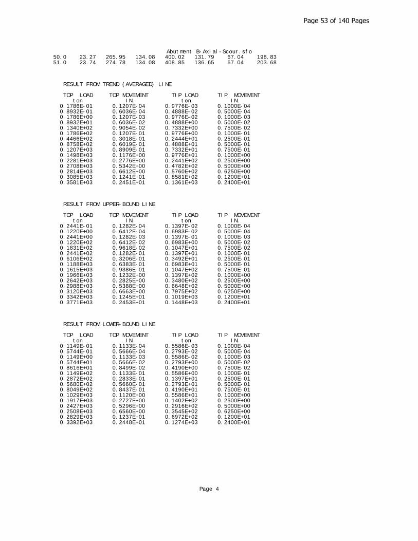
Abutment B-Axial-Scour.sfo 50.0 23.27 265.95 134.08 400.02 131.79 67.04 198.83 51.0 23.74 274.78 134.08 408.85 136.65 67.04 203.68
RESULT FROM TREND (AVERAGED) LINE
TOP LOAD TOP MOVEMENT TIP LOAD TIP MOVEMENT ton IN. ton IN. 0.1786E-01 0.1207E-04 0.9776E-03 0.1000E-04 0.8932E-01 0.6036E-04 0.4888E-02 0.5000E-04 0.1786E+00 0.1207E-03 0.9776E-02 0.1000E-03 0.8932E+01 0.6036E-02 0.4888E+00 0.5000E-02 0.1340E+02 0.9054E-02 0.7332E+00 0.7500E-02 0.1786E+02 0.1207E-01 0.9776E+00 0.1000E-01 0.4466E+02 0.3018E-01 0.2444E+01 0.2500E-01 0.8758E+02 0.6019E-01 0.4888E+01 0.5000E-01 0.1207E+03 0.8909E-01 0.7332E+01 0.7500E-01 0.1498E+03 0.1176E+00 0.9776E+01 0.1000E+00 0.2281E+03 0.2776E+00 0.2441E+02 0.2500E+00 0.2708E+03 0.5342E+00 0.4782E+02 0.5000E+00 0.2814E+03 0.6612E+00 0.5760E+02 0.6250E+00 0.3085E+03 0.1241E+01 0.8581E+02 0.1200E+01 0.3581E+03 0.2451E+01 0.1361E+03 0.2400E+01
RESULT FROM UPPER-BOUND LINE
TOP LOAD TOP MOVEMENT TIP LOAD TIP MOVEMENT ton IN. ton IN. 0.2441E-01 0.1282E-04 0.1397E-02 0.1000E-04 0.1220E+00 0.6412E-04 0.6983E-02 0.5000E-04 0.2441E+00 0.1282E-03 0.1397E-01 0.1000E-03 0.1220E+02 0.6412E-02 0.6983E+00 0.5000E-02 0.1831E+02 0.9618E-02 0.1047E+01 0.7500E-02 0.2441E+02 0.1282E-01 0.1397E+01 0.1000E-01 0.6106E+02 0.3206E-01 0.3492E+01 0.2500E-01 0.1188E+03 0.6383E-01 0.6983E+01 0.5000E-01 0.1615E+03 0.9386E-01 0.1047E+02 0.7500E-01 0.1966E+03 0.1232E+00 0.1397E+02 0.1000E+00 0.2642E+03 0.2825E+00 0.3480E+02 0.2500E+00 0.2988E+03 0.5388E+00 0.6648E+02 0.5000E+00 0.3120E+03 0.6663E+00 0.7975E+02 0.6250E+00 0.3342E+03 0.1245E+01 0.1019E+03 0.1200E+01 0.3771E+03 0.2453E+01 0.1448E+03 0.2400E+01
RESULT FROM LOWER-BOUND LINE
TOP LOAD TOP MOVEMENT TIP LOAD TIP MOVEMENT ton IN. ton IN. 0.1149E-01 0.1133E-04 0.5586E-03 0.1000E-04 0.5744E-01 0.5666E-04 0.2793E-02 0.5000E-04 0.1149E+00 0.1133E-03 0.5586E-02 0.1000E-03 0.5744E+01 0.5666E-02 0.2793E+00 0.5000E-02 0.8616E+01 0.8499E-02 0.4190E+00 0.7500E-02 0.1149E+02 0.1133E-01 0.5586E+00 0.1000E-01 0.2872E+02 0.2833E-01 0.1397E+01 0.2500E-01 0.5680E+02 0.5660E-01 0.2793E+01 0.5000E-01 0.8049E+02 0.8437E-01 0.4190E+01 0.7500E-01 0.1029E+03 0.1120E+00 0.5586E+01 0.1000E+00 0.1917E+03 0.2727E+00 0.1402E+02 0.2500E+00 0.2427E+03 0.5296E+00 0.2916E+02 0.5000E+00 0.2508E+03 0.6560E+00 0.3545E+02 0.6250E+00 0.2829E+03 0.1237E+01 0.6972E+02 0.1200E+01 0.3392E+03 0.2448E+01 0.1274E+03 0.2400E+01
Page 4
Page 53 of 140 Pages

Deflection (in) Moment (lbs-in) Shear Force (kips)D
epth
(ft
)
Dep
th (
ft)
Dep
th (
ft)
-0.1 0 0.1 0.2 0.3 0.4 0.5 0.6 0.7 0.80
24
68
1012
1416
1820
2224
2628
3032
3436
380 1000 2000 3000 4000 5000 6000 7000
02
46
810
1214
1618
2022
2426
2830
3234
3638
-40 -30 -20 -10 0 10 20 30
02
46
810
1214
1618
2022
2426
2830
3234
3638
Load Case 1
Load Case 2
Load Case 3
Load Case 4
Page 54 of 140 Pages
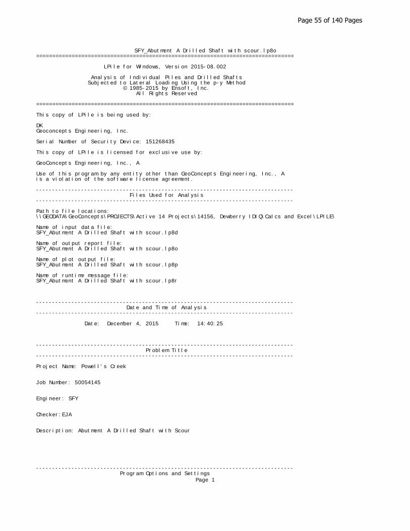
SFY_Abutment A Drilled Shaft with scour.lp8o================================================================================
LPile for Windows, Version 2015-08.002
Analysis of Individual Piles and Drilled Shafts Subjected to Lateral Loading Using the p-y Method © 1985-2015 by Ensoft, Inc. All Rights Reserved
================================================================================
This copy of LPile is being used by:
DKGeoconcepts Engineering, Inc.
Serial Number of Security Device: 151268435
This copy of LPile is licensed for exclusive use by:
GeoConcepts Engineering, Inc., A
Use of this program by any entity other than GeoConcepts Engineering, Inc., Ais a violation of the software license agreement.
-------------------------------------------------------------------------------- Files Used for Analysis--------------------------------------------------------------------------------
Path to file locations:\\GEODATA\GeoConcepts\PROJECTS\Active 14 Projects\14156, Dewberry IDIQ\Calcs and Excel\LPILE\
Name of input data file: SFY_Abutment A Drilled Shaft with scour.lp8d
Name of output report file: SFY_Abutment A Drilled Shaft with scour.lp8o
Name of plot output file: SFY_Abutment A Drilled Shaft with scour.lp8p
Name of runtime message file: SFY_Abutment A Drilled Shaft with scour.lp8r
-------------------------------------------------------------------------------- Date and Time of Analysis--------------------------------------------------------------------------------
Date: December 4, 2015 Time: 14:40:25
-------------------------------------------------------------------------------- Problem Title--------------------------------------------------------------------------------
Project Name: Powell's Creek Job Number: 50054145 Engineer: SFY Checker:EJA Description: Abutment A Drilled Shaft with Scour
-------------------------------------------------------------------------------- Program Options and Settings
Page 1
Page 55 of 140 Pages

SFY_Abutment A Drilled Shaft with scour.lp8o--------------------------------------------------------------------------------
Computational Options: - Use unfactored loads in computations (conventional analysis)Engineering Units Used for Data Input and Computations: - US Customary System Units (pounds, feet, inches)
Analysis Control Options: - Maximum number of iterations allowed = 500 - Deflection tolerance for convergence = 1.0000E-05 in - Maximum allowable deflection = 100.0000 in - Number of pile increments = 92
Loading Type and Number of Cycles of Loading: - Static loading specified
- Analysis uses p-y modification factors for p-y curves - No distributed lateral loads are entered - Loading by lateral soil movements acting on pile not selected - Input of shear resistance at the pile tip not selected - Computation of pile-head foundation stiffness matrix not selected - Push-over analysis of pile not selected - Buckling analysis of pile not selected
Output Options: - Output files use decimal points to denote decimal symbols. - Values of pile-head deflection, bending moment, shear force, and soil reaction are printed for full length of pile. - Printing Increment (nodal spacing of output points) = 1 - No p-y curves to be computed and reported for user-specified depths - Print using wide report formats
-------------------------------------------------------------------------------- Pile Structural Properties and Geometry--------------------------------------------------------------------------------
Total number of pile sections = 1
Total length of pile = 40.00 ft
Depth of ground surface below top of pile = 9.63 ft
Pile diameters used for p-y curve computations are defined using 2 points.
p-y curves are computed using pile diameter values interpolated with depth over the length of the pile.
Point Depth Pile X Diameter ft in----- --------- ----------- 1 0.00000 48.00000000 2 40.0000000 48.00000000
Input Structural Properties:----------------------------
Pile Section No. 1:
Section Type = Drilled Shaft (Bored Pile) Section Length = 40.000000 ft Section Diameter = 48.000000 in Shear Capacity of Section = 0.0000 lbs
-------------------------------------------------------------------------------- Ground Slope and Pile Batter Angles--------------------------------------------------------------------------------
Ground Slope Angle = 0.000 degrees = 0.000 radians
Pile Batter Angle = 0.000 degreesPage 2
Page 56 of 140 Pages

SFY_Abutment A Drilled Shaft with scour.lp8o = 0.000 radians
-------------------------------------------------------------------------------- Soil and Rock Layering Information--------------------------------------------------------------------------------
The soil profile is modelled using 3 layers
Layer 1 is sand, p-y criteria by Reese et al., 1974
Distance from top of pile to top of layer = 9.630000 ft Distance from top of pile to bottom of layer = 13.300000 ft Effective unit weight at top of layer = 57.600000 pcf Effective unit weight at bottom of layer = 57.600000 pcf Friction angle at top of layer = 32.000000 deg. Friction angle at bottom of layer = 32.000000 deg. Subgrade k at top of layer = 75.000000 pci Subgrade k at bottom of layer = 75.000000 pci
Layer 2 is stiff clay without free water
Distance from top of pile to top of layer = 13.300000 ft Distance from top of pile to bottom of layer = 18.300000 ft Effective unit weight at top of layer = 52.600000 pcf Effective unit weight at bottom of layer = 52.600000 pcf Undrained cohesion at top of layer = 1500. psf Undrained cohesion at bottom of layer = 1500. psf Epsilon-50 at top of layer = 0.008000 Epsilon-50 at bottom of layer = 0.008000
Layer 3 is sand, p-y criteria by Reese et al., 1974
Distance from top of pile to top of layer = 18.300000 ft Distance from top of pile to bottom of layer = 50.000000 ft Effective unit weight at top of layer = 57.600000 pcf Effective unit weight at bottom of layer = 57.600000 pcf Friction angle at top of layer = 34.000000 deg. Friction angle at bottom of layer = 34.000000 deg. Subgrade k at top of layer = 100.000000 pci Subgrade k at bottom of layer = 100.000000 pci
(Depth of lowest soil layer extends 10.00 ft below pile tip)
-------------------------------------------------------------------------------- Summary of Input Soil Properties--------------------------------------------------------------------------------
Layer Soil Type Layer Effective Undrained Angle of E50 Layer Name Depth Unit Wt. Cohesion Friction or kpy Num. (p-y Curve Type) ft pcf psf deg. krm pci ----- ------------------- ---------- ---------- ---------- ---------- ---------- ---------- 1 Sand 9.6300 57.6000 -- 32.0000 -- 75.0000 (Reese, et al.) 13.3000 57.6000 -- 32.0000 -- 75.0000 2 Stiff Clay 13.3000 52.6000 1500. -- 0.00800 -- w/o Free Water 18.3000 52.6000 1500. -- 0.00800 -- 3 Sand 18.3000 57.6000 -- 34.0000 -- 100.0000 (Reese, et al.) 50.0000 57.6000 -- 34.0000 -- 100.0000
-------------------------------------------------------------------------------- p-y Modification Factors for Group Action--------------------------------------------------------------------------------
Distribution of p-y modifiers with depth defined using 2 pointsPage 3
Page 57 of 140 Pages

SFY_Abutment A Drilled Shaft with scour.lp8o
Point Depth X p-mult y-mult No. ft----- ---------- ---------- ---------- 1 16.500 1.0000 1.0000 2 48.000 1.0000 1.0000
-------------------------------------------------------------------------------- Static Loading Type--------------------------------------------------------------------------------
Static loading criteria were used when computing p-y curves for all analyses.
-------------------------------------------------------------------------------- Pile-head Loading and Pile-head Fixity Conditions--------------------------------------------------------------------------------
Number of loads specified = 4
Load Load Condition Condition Axial Thrust Compute Top y No. Type 1 2 Force, lbs vs. Pile Length----- ---- -------------------- ----------------------- ---------------- --------------- 1 1 V = 23269. lbs M = 1112698. in-lbs 167644. Yes 2 1 V = 28753. lbs M = 1558633. in-lbs 96931. Yes 3 1 V = 28753. lbs M = 1543354. in-lbs 135553. Yes 4 1 V = 18926. lbs M = 1046542. in-lbs 124321. Yes
V = perpendicular shear force applied to pile headM = bending moment applied to pile heady = lateral deflection relative to pile axisS = pile slope relative to original pile batter angleR = rotational stiffness applied to pile headValues of top y vs. pile lengths can be computed only for load types withspecified shear loading.Axial thrust is assumed to be acting axially for all pile batter angles.
-------------------------------------------------------------------------------- Computations of Nominal Moment Capacity and Nonlinear Bending Stiffness--------------------------------------------------------------------------------
Axial thrust force values were determined from pile-head loading conditions
Number of Pile Sections Analyzed = 1
Pile Section No. 1:-------------------
Dimensions and Properties of Drilled Shaft (Bored Pile):--------------------------------------------------------
Length of Section = 40.000000 ftShaft Diameter = 48.000000in Concrete Cover Thickness = 3.000000in Number of Reinforcing Bars = 19 bars Yield Stress of Reinforcing Bars = 60000. psiModulus of Elasticity of Reinforcing Bars = 29000000. psiGross Area of Shaft = 1810.sq. in. Total Area of Reinforcing Steel = 19.000000sq. in. Area Ratio of Steel Reinforcement = 1.05 percentEdge-to-Edge Bar Spacing = 5.599310in Maximum Concrete Aggregate Size = 0.750000in Ratio of Bar Spacing to Aggregate Size = 7.47Offset of Center of Rebar Cage from Center of Pile = 0.0000in
Axial Structural Capacities:----------------------------
Nom. Axial Structural Capacity = 0.85 Fc Ac + Fy As = 5705.921 kips Tensile Load for Cracking of Concrete = -712.114 kips Nominal Axial Tensile Capacity = -1140.000 kips
Page 4
Page 58 of 140 Pages
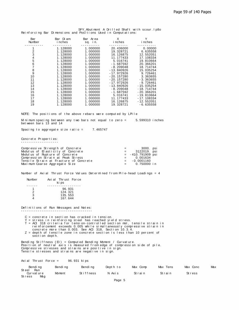
SFY_Abutment A Drilled Shaft with scour.lp8oReinforcing Bar Dimensions and Positions Used in Computations:
Bar Bar Diam. Bar Area X Y Number inches sq. in. inches inches ---------- ---------- ---------- ---------- ---------- 1 1.128000 1.000000 20.436000 0.00000 2 1.128000 1.000000 19.328721 6.635558 3 1.128000 1.000000 16.126875 12.552051 4 1.128000 1.000000 11.177433 17.108334 5 1.128000 1.000000 5.016741 19.810664 6 1.128000 1.000000 -1.687592 20.366201 7 1.128000 1.000000 -8.209048 18.714744 8 1.128000 1.000000 -13.840926 15.035254 9 1.128000 1.000000 -17.972926 9.726461 10 1.128000 1.000000 -20.157280 3.363655 11 1.128000 1.000000 -20.157280 -3.363655 12 1.128000 1.000000 -17.972926 -9.726461 13 1.128000 1.000000 -13.840926 -15.035254 14 1.128000 1.000000 -8.209048 -18.714744 15 1.128000 1.000000 -1.687592 -20.366201 16 1.128000 1.000000 5.016741 -19.810664 17 1.128000 1.000000 11.177433 -17.108334 18 1.128000 1.000000 16.126875 -12.552051 19 1.128000 1.000000 19.328721 -6.635558
NOTE: The positions of the above rebars were computed by LPile
Minimum spacing between any two bars not equal to zero = 5.599310 inchesbetween bars 13 and 14
Spacing to aggregate size ratio = 7.465747
Concrete Properties:--------------------
Compressive Strength of Concrete = 3000. psiModulus of Elasticity of Concrete = 3122019. psiModulus of Rupture of Concrete = -410.791909 psiCompression Strain at Peak Stress = 0.001634Tensile Strain at Fracture of Concrete = -0.0001160Maximum Coarse Aggregate Size = 0.750000 in
Number of Axial Thrust Force Values Determined from Pile-head Loadings = 4
Number Axial Thrust Force kips ------ ------------------ 1 96.931 2 124.321 3 135.553 4 167.644
Definitions of Run Messages and Notes:--------------------------------------
C = concrete in section has cracked in tension. Y = stress in reinforcing steel has reached yield stress. T = ACI 318 criteria for tension-controlled section met, tensile strain in reinforcement exceeds 0.005 while simultaneously compressive strain in concrete more than 0.003. See ACI 318, Section 10.3.4. Z = depth of tensile zone in concrete section is less than 10 percent of section depth.
Bending Stiffness (EI) = Computed Bending Moment / Curvature.Position of neutral axis is measured from edge of compression side of pile.Compressive stresses and strains are positive in sign.Tensile stresses and strains are negative in sign.
Axial Thrust Force = 96.931 kips
Bending Bending Bending Depth to Max Comp Max Tens Max Conc Max Steel Run Curvature Moment Stiffness N Axis Strain Strain Stress Stress Msg
Page 5
Page 59 of 140 Pages

SFY_Abutment A Drilled Shaft with scour.lp8o rad/in. in-kip kip-in2 in in/in in/in ksi ksi ------------- ------------- ------------- ------------- ------------- ------------- ------------- ------------- --- 6.25000E-07 656.1608347 1049857335. 45.8685863 0.00002867 -0.00000133 0.1038308 0.8270181 0.00000125 1311. 1048958618. 34.9662637 0.00004371 -0.00001629 0.1573170 1.2588271 0.00000188 1963. 1046923337. 31.3355670 0.00005875 -0.00003125 0.2103275 1.6908215 0.00000250 2611. 1044464721. 29.5210153 0.00007380 -0.00004620 0.2628459 2.1228736 0.00000313 3256. 1041821434. 28.4326137 0.00008885 -0.00006115 0.3148689 2.5549556 0.00000375 3897. 1039082555. 27.7071996 0.0001039 -0.00007610 0.3663952 2.9870580 0.00000438 4534. 1036288101. 27.1891757 0.0001190 -0.00009105 0.4174242 3.4191767 0.00000500 5167. 1033458560. 26.8007572 0.0001340 -0.0001060 0.4679557 3.8513098 0.00000563 5167. 918629831. 19.4144117 0.0001092 -0.0001608 0.3830733 -4.6238741 C 0.00000625 5167. 826766848. 18.8377236 0.0001177 -0.0001823 0.4117406 -5.2421626 C 0.00000688 5167. 751606226. 18.3523200 0.0001262 -0.0002038 0.4399335 -5.8631562 C 0.00000750 5167. 688972373. 17.9379275 0.0001345 -0.0002255 0.4677217 -6.4863007 C 0.00000813 5167. 635974499. 17.5789628 0.0001428 -0.0002472 0.4951313 -7.1114069 C 0.00000875 5167. 590547749. 17.2643479 0.0001511 -0.0002689 0.5221893 -7.7382717 C 0.00000938 5167. 551177899. 16.9891856 0.0001593 -0.0002907 0.5490226 -8.3658151 C 0.00001000 5167. 516729280. 16.7428034 0.0001674 -0.0003126 0.5755245 -8.9949870 C 0.00001063 5167. 486333440. 16.5248283 0.0001756 -0.0003344 0.6018621 -9.6243373 C 0.00001125 5167. 459314916. 16.3262140 0.0001837 -0.0003563 0.6278774 -10.2552726 C 0.00001188 5167. 435140446. 16.1489957 0.0001918 -0.0003782 0.6537696 -10.8860396 C 0.00001250 5167. 413383424. 15.9868926 0.0001998 -0.0004002 0.6794145 -11.5177514 C 0.00001313 5167. 393698499. 15.8385444 0.0002079 -0.0004221 0.7048475 -12.1501040 C 0.00001375 5167. 375803113. 15.7041070 0.0002159 -0.0004441 0.7301591 -12.7822873 C 0.00001438 5167. 359463847. 15.5811260 0.0002240 -0.0004660 0.7553195 -13.4145681 C 0.00001500 5167. 344486187. 15.4654354 0.0002320 -0.0004880 0.7801996 -14.0481355 C 0.00001563 5167. 330706739. 15.3593779 0.0002400 -0.0005100 0.8049596 -14.6815319 C 0.00001625 5167. 317987249. 15.2618430 0.0002480 -0.0005320 0.8295992 -15.3147564 C 0.00001688 5167. 306209944. 15.1718852 0.0002560 -0.0005540 0.8541182 -15.9478086 C 0.00001750 5235. 299167939. 15.0875556 0.0002640 -0.0005760 0.8784548 -16.5812655 C 0.00001813 5381. 296879514. 15.0076211 0.0002720 -0.0005980 0.9025736 -17.2154691 C 0.00001875 5526. 294737712. 14.9333384 0.0002800 -0.0006200 0.9265729 -17.8494972 C 0.00001938 5672. 292728325. 14.8641616 0.0002880 -0.0006420 0.9504526 -18.4833491 C 0.00002000 5817. 290838918. 14.7996132 0.0002960 -0.0006640 0.9742124 -19.1170243 C 0.00002063 5962. 289058567. 14.7392736 0.0003040 -0.0006860 0.9978520 -19.7505219 C 0.00002125 6107. 287377629. 14.6827725 0.0003120 -0.0007080 1.0213712 -20.3838414 C 0.00002188 6252. 285786100. 14.6294033 0.0003200 -0.0007300 1.0447452 -21.0172222 C 0.00002250 6396. 284272221. 14.5777836 0.0003280 -0.0007520 1.0678997 -21.6513961 C 0.00002313 6541. 282835350. 14.5292268 0.0003360 -0.0007740 1.0909347 -22.2853872 C 0.00002375 6685. 281469391. 14.4834921 0.0003440 -0.0007960 1.1138500
Page 6
Page 60 of 140 Pages
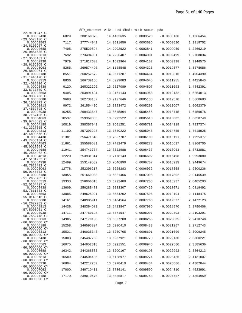
SFY_Abutment A Drilled Shaft with scour.lp8o-22.9191947 C 0.00002438 6829. 280168873. 14.4403635 0.0003520 -0.0008180 1.1366454 -23.5528180 C 0.00002563 7117. 277744942. 14.3611656 0.0003680 -0.0008620 1.1818752 -24.8195087 C 0.00002688 7405. 275529594. 14.2902922 0.0003841 -0.0009059 1.2266219 -26.0854535 C 0.00002813 7692. 273494901. 14.2266407 0.0004001 -0.0009499 1.2708834 -27.3506461 C 0.00002938 7979. 271617688. 14.1692964 0.0004162 -0.0009938 1.3146575 -28.6150805 C 0.00003063 8265. 269874406. 14.1158548 0.0004323 -0.0010377 1.3578056 -29.8802064 C 0.00003188 8551. 268252572. 14.0671287 0.0004484 -0.0010816 1.4004390 -31.1448478 C 0.00003313 8836. 266739150. 14.0229083 0.0004645 -0.0011255 1.4425843 -32.4086936 C 0.00003438 9120. 265322209. 13.9827089 0.0004807 -0.0011693 1.4842391 -33.6717369 C 0.00003563 9405. 263991494. 13.9461143 0.0004968 -0.0012132 1.5254013 -34.9339706 C 0.00003688 9688. 262738137. 13.9127646 0.0005130 -0.0012570 1.5660683 -36.1953873 C 0.00003813 9972. 261554430. 13.8823472 0.0005293 -0.0013007 1.6062379 -37.4559798 C 0.00003938 10255. 260433647. 13.8545894 0.0005455 -0.0013445 1.6459076 -38.7157406 C 0.00004063 10537. 259369883. 13.8292522 0.0005618 -0.0013882 1.6850749 -39.9746622 C 0.00004188 10819. 258357941. 13.8061251 0.0005781 -0.0014319 1.7237374 -41.2327368 C 0.00004313 11100. 257393223. 13.7850222 0.0005945 -0.0014755 1.7618925 -42.4899565 C 0.00004438 11381. 256471648. 13.7657787 0.0006109 -0.0015191 1.7995377 -43.7463134 C 0.00004563 11661. 255589581. 13.7482479 0.0006273 -0.0015627 1.8366705 -45.0017994 C 0.00004688 11941. 254743774. 13.7322988 0.0006437 -0.0016063 1.8732881 -46.2564062 C 0.00004813 12220. 253931314. 13.7178143 0.0006602 -0.0016498 1.9093880 -47.5101253 C 0.00004938 12499. 253149582. 13.7046890 0.0006767 -0.0016933 1.9449674 -48.7629482 C 0.00005063 12778. 252396217. 13.6928283 0.0006932 -0.0017368 1.9800236 -50.0148663 C 0.00005188 13055. 251669083. 13.6821466 0.0007098 -0.0017802 2.0145539 -51.2658705 C 0.00005313 13333. 250966013. 13.6722480 0.0007263 -0.0018237 2.0485203 -52.5164427 C 0.00005438 13609. 250285478. 13.6633307 0.0007429 -0.0018671 2.0819492 -53.7661853 C 0.00005563 13885. 249625921. 13.6554202 0.0007596 -0.0019104 2.1148475 -55.0149516 C 0.00005688 14161. 248985911. 13.6484564 0.0007763 -0.0019537 2.1472123 -56.2627282 C 0.00005813 14436. 248364081. 13.6423847 0.0007930 -0.0019970 2.1790406 -57.5095061 C 0.00005938 14711. 247759198. 13.6371547 0.0008097 -0.0020403 2.2103291 -58.7552748 C 0.00006063 14985. 247170130. 13.6327208 0.0008265 -0.0020835 2.2410748 -60.0000000 CY 0.00006188 15258. 246595834. 13.6290410 0.0008433 -0.0021267 2.2712743 -60.0000000 CY 0.00006313 15531. 246035348. 13.6260765 0.0008601 -0.0021699 2.3009245 -60.0000000 CY 0.00006438 15803. 245487783. 13.6237921 0.0008770 -0.0022130 2.3300221 -60.0000000 CY 0.00006563 16075. 244952318. 13.6221551 0.0008940 -0.0022560 2.3585636 -60.0000000 CY 0.00006688 16342. 244368583. 13.6200167 0.0009108 -0.0022992 2.3864213 -60.0000000 CY 0.00006813 16589. 243504435. 13.6128977 0.0009274 -0.0023426 2.4131007 -60.0000000 CY 0.00006938 16804. 242217262. 13.5978419 0.0009434 -0.0023866 2.4382844 -60.0000000 CY 0.00007063 17000. 240710411. 13.5786141 0.0009590 -0.0024310 2.4623991 -60.0000000 CY 0.00007188 17179. 239010476. 13.5555817 0.0009743 -0.0024757 2.4854959 -60.0000000 CY
Page 7
Page 61 of 140 Pages

SFY_Abutment A Drilled Shaft with scour.lp8o 0.00007313 17345. 237200978. 13.5303529 0.0009894 -0.0025206 2.5077609 -60.0000000 CY 0.00007438 17507. 235385057. 13.5049971 0.0010044 -0.0025656 2.5294281 -60.0000000 CY 0.00007938 18057. 227485995. 13.3892326 0.0010628 -0.0027472 2.6088731 -60.0000000 CY 0.00008438 18503. 219299164. 13.2642295 0.0011192 -0.0029308 2.6786536 -60.0000000 CY 0.00008938 18898. 211446344. 13.1409835 0.0011745 -0.0031155 2.7404037 -60.0000000 CY 0.00009438 19214. 203586871. 13.0090805 0.0012277 -0.0033023 2.7936018 -60.0000000 CY 0.00009938 19515. 196373018. 12.8902760 0.0012810 -0.0034890 2.8406921 -60.0000000 CY 0.0001044 19753. 189245556. 12.7673473 0.0013326 -0.0036774 2.8805100 -60.0000000 CY 0.0001094 19978. 182656587. 12.6520892 0.0013838 -0.0038662 2.9143698 -60.0000000 CY 0.0001144 20191. 176533077. 12.5439289 0.0014347 -0.0040553 2.9424284 -60.0000000 CY 0.0001194 20358. 170540404. 12.4327383 0.0014842 -0.0042458 2.9643600 -60.0000000 CY 0.0001244 20514. 164937508. 12.3298283 0.0015335 -0.0044365 2.9810339 -60.0000000 CY 0.0001294 20668. 159749628. 12.2370676 0.0015832 -0.0046268 2.9925440 -60.0000000 CY 0.0001344 20814. 154892496. 12.1466962 0.0016322 -0.0048178 2.9987311 -60.0000000 CY 0.0001394 20930. 150171441. 12.0545895 0.0016801 -0.0050099 2.9972790 -60.0000000 CY 0.0001444 21030. 145664484. 11.9655662 0.0017275 -0.0052025 2.9998880 -60.0000000 CY 0.0001494 21128. 141441776. 11.8844503 0.0017752 -0.0053948 2.9984133 -60.0000000 CY 0.0001544 21224. 137481206. 11.8104945 0.0018232 -0.0055868 2.9990785 -60.0000000 CY 0.0001594 21317. 133754059. 11.7418978 0.0018714 -0.0057786 2.9989920 -60.0000000 CY 0.0001644 21407. 130230227. 11.6750314 0.0019191 -0.0059709 2.9980527 -60.0000000 CY 0.0001694 21481. 126822389. 11.6076197 0.0019660 -0.0061640 2.9987483 -60.0000000 CY 0.0001744 21541. 123530997. 11.5396148 0.0020122 -0.0063578 2.9995821 -60.0000000 CY 0.0001794 21597. 120400481. 11.4757231 0.0020585 -0.0065515 2.9973391 -60.0000000 CY 0.0001844 21652. 117434026. 11.4162053 0.0021049 -0.0067451 2.9997318 -60.0000000 CY 0.0001894 21706. 114618857. 11.3610894 0.0021515 -0.0069385 2.9962616 60.0000000 CY 0.0001944 21759. 111944047. 11.3099089 0.0021984 -0.0071316 2.9980503 60.0000000 CY 0.0001994 21811. 109397649. 11.2605241 0.0022451 -0.0073249 2.9998751 60.0000000 CY 0.0002044 21861. 106967325. 11.2120612 0.0022915 -0.0075185 2.9957924 60.0000000 CY 0.0002094 21911. 104647175. 11.1664639 0.0023380 -0.0077120 2.9972642 60.0000000 CY 0.0002144 21956. 102416438. 11.1217543 0.0023842 -0.0079058 2.9995003 60.0000000 CY 0.0002194 21994. 100259697. 11.0768816 0.0024300 -0.0081000 2.9986120 60.0000000 CY 0.0002244 22028. 98173984. 11.0321049 0.0024753 -0.0082947 2.9938969 60.0000000 CY 0.0002294 22057. 96162011. 10.9877854 0.0025203 -0.0084897 2.9972913 60.0000000 CY 0.0002344 22086. 94233069. 10.9456246 0.0025654 -0.0086846 2.9993292 60.0000000 CY 0.0002394 22114. 92382606. 10.9055862 0.0026105 -0.0088795 2.9999343 60.0000000 CY 0.0002444 22142. 90605653. 10.8679811 0.0026559 -0.0090741 2.9947543 60.0000000 CY 0.0002494 22169. 88899150. 10.8322663 0.0027013 -0.0092687 2.9945835 60.0000000 CY 0.0002544 22196. 87258708. 10.7981431 0.0027468 -0.0094632 2.9975450 60.0000000 CY 0.0002594 22222. 85676692. 10.7621418 0.0027914 -0.0096586 2.9993042 60.0000000 CY 0.0002644 22248. 84153828. 10.7278623 0.0028362 -0.0098538 2.9999903
Page 8
Page 62 of 140 Pages
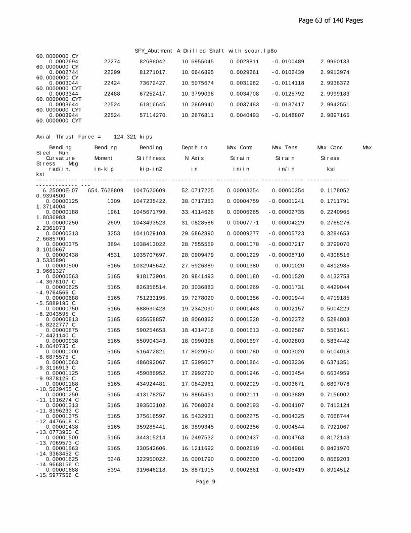
SFY_Abutment A Drilled Shaft with scour.lp8o60.0000000 CY 0.0002694 22274. 82686042. 10.6955045 0.0028811 -0.0100489 2.9960133 60.0000000 CY 0.0002744 22299. 81271017. 10.6646895 0.0029261 -0.0102439 2.9913974 60.0000000 CY 0.0003044 22424. 73672427. 10.5075674 0.0031982 -0.0114118 2.9936372 60.0000000 CYT 0.0003344 22488. 67252417. 10.3799098 0.0034708 -0.0125792 2.9999183 60.0000000 CYT 0.0003644 22524. 61816645. 10.2869940 0.0037483 -0.0137417 2.9942551 60.0000000 CYT 0.0003944 22524. 57114270. 10.2676811 0.0040493 -0.0148807 2.9897165 60.0000000 CYT
Axial Thrust Force = 124.321 kips
Bending Bending Bending Depth to Max Comp Max Tens Max Conc Max Steel Run Curvature Moment Stiffness N Axis Strain Strain Stress Stress Msg rad/in. in-kip kip-in2 in in/in in/in ksi ksi ------------- ------------- ------------- ------------- ------------- ------------- ------------- ------------- --- 6.25000E-07 654.7628809 1047620609. 52.0717225 0.00003254 0.00000254 0.1178052 0.9394500 0.00000125 1309. 1047235422. 38.0717353 0.00004759 -0.00001241 0.1711791 1.3714004 0.00000188 1961. 1045671799. 33.4114626 0.00006265 -0.00002735 0.2240965 1.8036983 0.00000250 2609. 1043493523. 31.0828586 0.00007771 -0.00004229 0.2765276 2.2361073 0.00000313 3253. 1041029103. 29.6862890 0.00009277 -0.00005723 0.3284653 2.6685700 0.00000375 3894. 1038413022. 28.7555559 0.0001078 -0.00007217 0.3799070 3.1010667 0.00000438 4531. 1035707697. 28.0909479 0.0001229 -0.00008710 0.4308516 3.5335890 0.00000500 5165. 1032945642. 27.5926389 0.0001380 -0.0001020 0.4812985 3.9661327 0.00000563 5165. 918173904. 20.9841493 0.0001180 -0.0001520 0.4132758 -4.3678107 C 0.00000625 5165. 826356514. 20.3036883 0.0001269 -0.0001731 0.4429044 -4.9764566 C 0.00000688 5165. 751233195. 19.7278020 0.0001356 -0.0001944 0.4719185 -5.5889195 C 0.00000750 5165. 688630428. 19.2342090 0.0001443 -0.0002157 0.5004229 -6.2043595 C 0.00000813 5165. 635658857. 18.8060362 0.0001528 -0.0002372 0.5284808 -6.8222777 C 0.00000875 5165. 590254653. 18.4314716 0.0001613 -0.0002587 0.5561611 -7.4421140 C 0.00000938 5165. 550904343. 18.0990398 0.0001697 -0.0002803 0.5834442 -8.0640735 C 0.00001000 5165. 516472821. 17.8029050 0.0001780 -0.0003020 0.6104018 -8.6875575 C 0.00001063 5165. 486092067. 17.5395007 0.0001864 -0.0003236 0.6371351 -9.3116913 C 0.00001125 5165. 459086952. 17.2992720 0.0001946 -0.0003454 0.6634959 -9.9378125 C 0.00001188 5165. 434924481. 17.0842961 0.0002029 -0.0003671 0.6897076 -10.5639455 C 0.00001250 5165. 413178257. 16.8865451 0.0002111 -0.0003889 0.7156002 -11.1916274 C 0.00001313 5165. 393503102. 16.7068024 0.0002193 -0.0004107 0.7413124 -11.8196233 C 0.00001375 5165. 375616597. 16.5432931 0.0002275 -0.0004325 0.7668744 -12.4476618 C 0.00001438 5165. 359285441. 16.3899345 0.0002356 -0.0004544 0.7921067 -13.0773960 C 0.00001500 5165. 344315214. 16.2497532 0.0002437 -0.0004763 0.8172143 -13.7069573 C 0.00001563 5165. 330542606. 16.1211692 0.0002519 -0.0004981 0.8421970 -14.3363452 C 0.00001625 5248. 322950022. 16.0001790 0.0002600 -0.0005200 0.8669203 -14.9668156 C 0.00001688 5394. 319646218. 15.8871915 0.0002681 -0.0005419 0.8914512 -15.5977556 C
Page 9
Page 63 of 140 Pages

SFY_Abutment A Drilled Shaft with scour.lp8o 0.00001750 5540. 316571655. 15.7826186 0.0002762 -0.0005638 0.9158587 -16.2285210 C 0.00001813 5686. 313702597. 15.6855910 0.0002843 -0.0005857 0.9401426 -16.8591112 C 0.00001875 5832. 311017473. 15.5951896 0.0002924 -0.0006076 0.9642930 -17.4896156 C 0.00001938 5977. 308482355. 15.5080843 0.0003005 -0.0006295 0.9881533 -18.1215451 C 0.00002000 6122. 306099874. 15.4267292 0.0003085 -0.0006515 1.0118912 -18.7532970 C 0.00002063 6267. 303856136. 15.3506027 0.0003166 -0.0006734 1.0355065 -19.3848707 C 0.00002125 6412. 301738878. 15.2792444 0.0003247 -0.0006953 1.0589989 -20.0162656 C 0.00002188 6557. 299737242. 15.2122466 0.0003328 -0.0007172 1.0823681 -20.6474810 C 0.00002250 6701. 297841574. 15.1492471 0.0003409 -0.0007391 1.1056140 -21.2785162 C 0.00002313 6846. 296037965. 15.0888096 0.0003489 -0.0007611 1.1286616 -21.9101170 C 0.00002375 6990. 294319516. 15.0307955 0.0003570 -0.0007830 1.1515162 -22.5422395 C 0.00002438 7134. 292684437. 14.9760167 0.0003650 -0.0008050 1.1742485 -23.1741781 C 0.00002563 7422. 289639923. 14.8752220 0.0003812 -0.0008488 1.2193455 -24.4375006 C 0.00002688 7709. 286861181. 14.7847588 0.0003973 -0.0008927 1.2639502 -25.7000785 C 0.00002813 7996. 284312654. 14.7032567 0.0004135 -0.0009365 1.3080605 -26.9619061 C 0.00002938 8283. 281963463. 14.6291838 0.0004297 -0.0009803 1.3516426 -28.2233140 C 0.00003063 8568. 279782982. 14.5598359 0.0004459 -0.0010241 1.3945473 -29.4858956 C 0.00003188 8854. 277758698. 14.4967733 0.0004621 -0.0010679 1.4369577 -30.7476951 C 0.00003313 9138. 275872820. 14.4392912 0.0004783 -0.0011117 1.4788716 -32.0087058 C 0.00003438 9423. 274110144. 14.3867877 0.0004945 -0.0011555 1.5202866 -33.2689209 C 0.00003563 9706. 272457601. 14.3387453 0.0005108 -0.0011992 1.5612004 -34.5283337 C 0.00003688 9990. 270903889. 14.2947168 0.0005271 -0.0012429 1.6016106 -35.7869371 C 0.00003813 10272. 269439190. 14.2543139 0.0005434 -0.0012866 1.6415147 -37.0447241 C 0.00003938 10555. 268054929. 14.2171976 0.0005598 -0.0013302 1.6809105 -38.3016874 C 0.00004063 10836. 266743586. 14.1830706 0.0005762 -0.0013738 1.7197953 -39.5578198 C 0.00004188 11118. 265497874. 14.1513392 0.0005926 -0.0014174 1.7581338 -40.8135173 C 0.00004313 11398. 264311028. 14.1212785 0.0006090 -0.0014610 1.7958725 -42.0694260 C 0.00004438 11679. 263179699. 14.0935932 0.0006254 -0.0015046 1.8330983 -43.3244572 C 0.00004563 11958. 262099234. 14.0680945 0.0006419 -0.0015481 1.8698084 -44.5786024 C 0.00004688 12237. 261065473. 14.0446137 0.0006583 -0.0015917 1.9060003 -45.8318531 C 0.00004813 12516. 260074688. 14.0229998 0.0006749 -0.0016351 1.9416711 -47.0842008 C 0.00004938 12794. 259123525. 14.0031172 0.0006914 -0.0016786 1.9768182 -48.3356364 C 0.00005063 13072. 258208963. 13.9848439 0.0007080 -0.0017220 2.0114387 -49.5861509 C 0.00005188 13349. 257328267. 13.9680695 0.0007246 -0.0017654 2.0455299 -50.8357353 C 0.00005313 13625. 256478962. 13.9526943 0.0007412 -0.0018088 2.0790888 -52.0843802 C 0.00005438 13901. 255658796. 13.9386279 0.0007579 -0.0018521 2.1121125 -53.3320760 C 0.00005563 14177. 254865719. 13.9257880 0.0007746 -0.0018954 2.1445981 -54.5788131 C 0.00005688 14452. 254097860. 13.9140998 0.0007914 -0.0019386 2.1765425 -55.8245815 C 0.00005813 14726. 253353509. 13.9034949 0.0008081 -0.0019819 2.2079428 -57.0693712 C 0.00005938 15000. 252631094. 13.8939109 0.0008250 -0.0020250 2.2387958
Page 10
Page 64 of 140 Pages
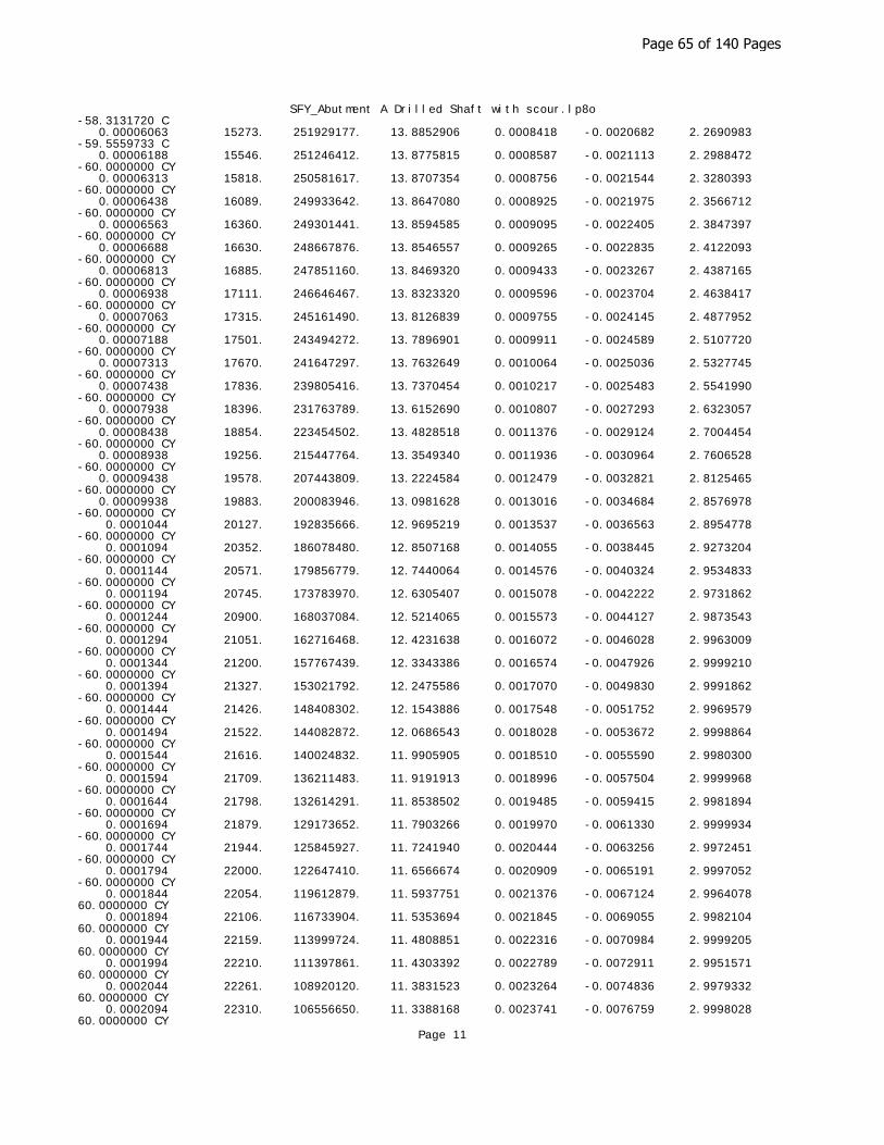
SFY_Abutment A Drilled Shaft with scour.lp8o-58.3131720 C 0.00006063 15273. 251929177. 13.8852906 0.0008418 -0.0020682 2.2690983 -59.5559733 C 0.00006188 15546. 251246412. 13.8775815 0.0008587 -0.0021113 2.2988472 -60.0000000 CY 0.00006313 15818. 250581617. 13.8707354 0.0008756 -0.0021544 2.3280393 -60.0000000 CY 0.00006438 16089. 249933642. 13.8647080 0.0008925 -0.0021975 2.3566712 -60.0000000 CY 0.00006563 16360. 249301441. 13.8594585 0.0009095 -0.0022405 2.3847397 -60.0000000 CY 0.00006688 16630. 248667876. 13.8546557 0.0009265 -0.0022835 2.4122093 -60.0000000 CY 0.00006813 16885. 247851160. 13.8469320 0.0009433 -0.0023267 2.4387165 -60.0000000 CY 0.00006938 17111. 246646467. 13.8323320 0.0009596 -0.0023704 2.4638417 -60.0000000 CY 0.00007063 17315. 245161490. 13.8126839 0.0009755 -0.0024145 2.4877952 -60.0000000 CY 0.00007188 17501. 243494272. 13.7896901 0.0009911 -0.0024589 2.5107720 -60.0000000 CY 0.00007313 17670. 241647297. 13.7632649 0.0010064 -0.0025036 2.5327745 -60.0000000 CY 0.00007438 17836. 239805416. 13.7370454 0.0010217 -0.0025483 2.5541990 -60.0000000 CY 0.00007938 18396. 231763789. 13.6152690 0.0010807 -0.0027293 2.6323057 -60.0000000 CY 0.00008438 18854. 223454502. 13.4828518 0.0011376 -0.0029124 2.7004454 -60.0000000 CY 0.00008938 19256. 215447764. 13.3549340 0.0011936 -0.0030964 2.7606528 -60.0000000 CY 0.00009438 19578. 207443809. 13.2224584 0.0012479 -0.0032821 2.8125465 -60.0000000 CY 0.00009938 19883. 200083946. 13.0981628 0.0013016 -0.0034684 2.8576978 -60.0000000 CY 0.0001044 20127. 192835666. 12.9695219 0.0013537 -0.0036563 2.8954778 -60.0000000 CY 0.0001094 20352. 186078480. 12.8507168 0.0014055 -0.0038445 2.9273204 -60.0000000 CY 0.0001144 20571. 179856779. 12.7440064 0.0014576 -0.0040324 2.9534833 -60.0000000 CY 0.0001194 20745. 173783970. 12.6305407 0.0015078 -0.0042222 2.9731862 -60.0000000 CY 0.0001244 20900. 168037084. 12.5214065 0.0015573 -0.0044127 2.9873543 -60.0000000 CY 0.0001294 21051. 162716468. 12.4231638 0.0016072 -0.0046028 2.9963009 -60.0000000 CY 0.0001344 21200. 157767439. 12.3343386 0.0016574 -0.0047926 2.9999210 -60.0000000 CY 0.0001394 21327. 153021792. 12.2475586 0.0017070 -0.0049830 2.9991862 -60.0000000 CY 0.0001444 21426. 148408302. 12.1543886 0.0017548 -0.0051752 2.9969579 -60.0000000 CY 0.0001494 21522. 144082872. 12.0686543 0.0018028 -0.0053672 2.9998864 -60.0000000 CY 0.0001544 21616. 140024832. 11.9905905 0.0018510 -0.0055590 2.9980300 -60.0000000 CY 0.0001594 21709. 136211483. 11.9191913 0.0018996 -0.0057504 2.9999968 -60.0000000 CY 0.0001644 21798. 132614291. 11.8538502 0.0019485 -0.0059415 2.9981894 -60.0000000 CY 0.0001694 21879. 129173652. 11.7903266 0.0019970 -0.0061330 2.9999934 -60.0000000 CY 0.0001744 21944. 125845927. 11.7241940 0.0020444 -0.0063256 2.9972451 -60.0000000 CY 0.0001794 22000. 122647410. 11.6566674 0.0020909 -0.0065191 2.9997052 -60.0000000 CY 0.0001844 22054. 119612879. 11.5937751 0.0021376 -0.0067124 2.9964078 60.0000000 CY 0.0001894 22106. 116733904. 11.5353694 0.0021845 -0.0069055 2.9982104 60.0000000 CY 0.0001944 22159. 113999724. 11.4808851 0.0022316 -0.0070984 2.9999205 60.0000000 CY 0.0001994 22210. 111397861. 11.4303392 0.0022789 -0.0072911 2.9951571 60.0000000 CY 0.0002044 22261. 108920120. 11.3831523 0.0023264 -0.0074836 2.9979332 60.0000000 CY 0.0002094 22310. 106556650. 11.3388168 0.0023741 -0.0076759 2.9998028 60.0000000 CY
Page 11
Page 65 of 140 Pages

SFY_Abutment A Drilled Shaft with scour.lp8o 0.0002144 22359. 104298379. 11.2973541 0.0024219 -0.0078681 2.9965599 60.0000000 CY 0.0002194 22400. 102107274. 11.2527916 0.0024686 -0.0080614 2.9959491 60.0000000 CY 0.0002244 22437. 99999688. 11.2078776 0.0025148 -0.0082552 2.9986819 60.0000000 CY 0.0002294 22467. 97949505. 11.1611841 0.0025601 -0.0084499 2.9999025 60.0000000 CY 0.0002344 22495. 95980571. 11.1166715 0.0026055 -0.0086445 2.9967469 60.0000000 CY 0.0002394 22523. 94090249. 11.0742642 0.0026509 -0.0088391 2.9938093 60.0000000 CY 0.0002444 22550. 92276182. 11.0339599 0.0026964 -0.0090336 2.9970201 60.0000000 CY 0.0002494 22577. 90534024. 10.9956733 0.0027420 -0.0092280 2.9990764 60.0000000 CY 0.0002544 22604. 88859520. 10.9592909 0.0027878 -0.0094222 2.9999630 60.0000000 CY 0.0002594 22630. 87247978. 10.9249607 0.0028337 -0.0096163 2.9963955 60.0000000 CY 0.0002644 22656. 85696542. 10.8923304 0.0028797 -0.0098103 2.9916177 60.0000000 CY 0.0002694 22681. 84199927. 10.8617753 0.0029259 -0.0100041 2.9952036 60.0000000 CY 0.0002744 22706. 82755387. 10.8331226 0.0029723 -0.0101977 2.9978165 60.0000000 CY 0.0003044 22831. 75010551. 10.6793986 0.0032505 -0.0113595 2.9955143 60.0000000 CYT 0.0003344 22891. 68457938. 10.5529983 0.0035287 -0.0125213 2.9897493 60.0000000 CYT 0.0003644 22923. 62909993. 10.4594276 0.0038112 -0.0136788 2.9999158 60.0000000 CYT
Axial Thrust Force = 135.553 kips
Bending Bending Bending Depth to Max Comp Max Tens Max Conc Max Steel Run Curvature Moment Stiffness N Axis Strain Strain Stress Stress Msg rad/in. in-kip kip-in2 in in/in in/in ksi ksi ------------- ------------- ------------- ------------- ------------- ------------- ------------- ------------- --- 6.25000E-07 654.1884659 1046701545. 54.6194518 0.00003414 0.00000414 0.1235350 0.9856276 0.00000125 1308. 1046447552. 39.3465636 0.00004918 -0.00001082 0.1768598 1.4176129 0.00000188 1960. 1045082260. 34.2633652 0.00006424 -0.00002576 0.2297371 1.8500205 0.00000250 2608. 1043031433. 31.7236948 0.00007931 -0.00004069 0.2821314 2.2825679 0.00000313 3252. 1040650417. 30.2006273 0.00009438 -0.00005562 0.3340334 2.7151819 0.00000375 3893. 1038092238. 29.1856282 0.0001094 -0.00007055 0.3854400 3.1478371 0.00000438 4530. 1035429216. 28.4608674 0.0001245 -0.00008548 0.4363496 3.5805226 0.00000500 5163. 1032699313. 27.9174674 0.0001396 -0.0001004 0.4867615 4.0132328 0.00000563 5793. 1029924253. 27.4949564 0.0001547 -0.0001153 0.5366754 4.4459648 0.00000625 5793. 926931828. 20.8742121 0.0001305 -0.0001695 0.4549817 -4.8730490 C 0.00000688 5793. 842665298. 20.2635119 0.0001393 -0.0001907 0.4843213 -5.4821123 C 0.00000750 5793. 772443190. 19.7401260 0.0001481 -0.0002119 0.5131279 -6.0943226 C 0.00000813 5793. 713024483. 19.2857104 0.0001567 -0.0002333 0.5414567 -6.7092545 C 0.00000875 5793. 662094163. 18.8875422 0.0001653 -0.0002547 0.5693723 -7.3263861 C 0.00000938 5793. 617954552. 18.5348717 0.0001738 -0.0002762 0.5968947 -7.9455817 C 0.00001000 5793. 579332392. 18.2192880 0.0001822 -0.0002978 0.6240316 -8.5668065 C 0.00001063 5793. 545254016. 17.9381098 0.0001906 -0.0003194 0.6509204 -9.1888699 C 0.00001125 5793. 514962127. 17.6827225 0.0001989 -0.0003411 0.6774580
Page 12
Page 66 of 140 Pages

SFY_Abutment A Drilled Shaft with scour.lp8o-9.8127117 C 0.00001188 5793. 487858857. 17.4527063 0.0002073 -0.0003627 0.7037872 -10.4370742 C 0.00001250 5793. 463465914. 17.2416340 0.0002155 -0.0003845 0.7298043 -11.0629076 C 0.00001313 5793. 441396109. 17.0511252 0.0002238 -0.0004062 0.7556923 -11.6885654 C 0.00001375 5793. 421332649. 16.8731870 0.0002320 -0.0004280 0.7812257 -12.3161167 C 0.00001438 5793. 403013838. 16.7108146 0.0002402 -0.0004498 0.8066171 -12.9436291 C 0.00001500 5793. 386221595. 16.5623756 0.0002484 -0.0004716 0.8318813 -13.5709666 C 0.00001563 5793. 370772731. 16.4216905 0.0002566 -0.0004934 0.8567993 -14.2001715 C 0.00001625 5793. 356512242. 16.2921244 0.0002647 -0.0005153 0.8815881 -14.8292363 C 0.00001688 5793. 343308084. 16.1725141 0.0002729 -0.0005371 0.9062513 -15.4581259 C 0.00001750 5793. 331047081. 16.0611619 0.0002811 -0.0005589 0.9307548 -16.0871603 C 0.00001813 5810. 320532792. 15.9548392 0.0002892 -0.0005808 0.9549685 -16.7175876 C 0.00001875 5955. 317615159. 15.8559296 0.0002973 -0.0006027 0.9790580 -17.3478382 C 0.00001938 6101. 314879585. 15.7637167 0.0003054 -0.0006246 1.0030231 -17.9779116 C 0.00002000 6246. 312308983. 15.6775737 0.0003136 -0.0006464 1.0268635 -18.6078072 C 0.00002063 6391. 309887689. 15.5968405 0.0003217 -0.0006683 1.0505724 -19.2375897 C 0.00002125 6536. 307587795. 15.5185322 0.0003298 -0.0006902 1.0739925 -19.8688045 C 0.00002188 6681. 305413940. 15.4449830 0.0003379 -0.0007121 1.0972893 -20.4998388 C 0.00002250 6826. 303355602. 15.3757974 0.0003460 -0.0007340 1.1204626 -21.1306921 C 0.00002313 6970. 301403398. 15.3106226 0.0003541 -0.0007559 1.1435119 -21.7613636 C 0.00002375 7114. 299548930. 15.2491429 0.0003622 -0.0007778 1.1664371 -22.3918528 C 0.00002438 7259. 297784664. 15.1910750 0.0003703 -0.0007997 1.1892379 -23.0221588 C 0.00002563 7546. 294494105. 15.0828438 0.0003865 -0.0008435 1.2343687 -24.2832117 C 0.00002688 7834. 291480945. 14.9832449 0.0004027 -0.0008873 1.2788226 -25.5453834 C 0.00002813 8120. 288718773. 14.8934243 0.0004189 -0.0009311 1.3227812 -26.8068007 C 0.00002938 8406. 286175430. 14.8121409 0.0004351 -0.0009749 1.3662423 -28.0674574 C 0.00003063 8692. 283824006. 14.7383562 0.0004514 -0.0010186 1.4092036 -29.3273474 C 0.00003188 8977. 281641813. 14.6711946 0.0004676 -0.0010624 1.4516627 -30.5864644 C 0.00003313 9262. 279605796. 14.6087591 0.0004839 -0.0011061 1.4935181 -31.8459107 C 0.00003438 9546. 277700153. 14.5505619 0.0005002 -0.0011498 1.5347732 -33.1056585 C 0.00003563 9829. 275914614. 14.4972301 0.0005165 -0.0011935 1.5755260 -34.3645990 C 0.00003688 10112. 274236863. 14.4482757 0.0005328 -0.0012372 1.6157741 -35.6227251 C 0.00003813 10395. 272656201. 14.4032745 0.0005491 -0.0012809 1.6555152 -36.8800295 C 0.00003938 10677. 271163282. 14.3618564 0.0005655 -0.0013245 1.6947466 -38.1365051 C 0.00004063 10959. 269749911. 14.3236970 0.0005819 -0.0013681 1.7334660 -39.3921444 C 0.00004188 11240. 268408870. 14.2885106 0.0005983 -0.0014117 1.7716708 -40.6469398 C 0.00004313 11520. 267133776. 14.2560449 0.0006148 -0.0014552 1.8093585 -41.9008837 C 0.00004438 11800. 265918964. 14.2260759 0.0006313 -0.0014987 1.8465264 -43.1539684 C 0.00004563 12080. 264759389. 14.1984046 0.0006478 -0.0015422 1.8831720 -44.4061858 C 0.00004688 12359. 263650541. 14.1728529 0.0006644 -0.0015856 1.9192926 -45.6575280 C
Page 13
Page 67 of 140 Pages
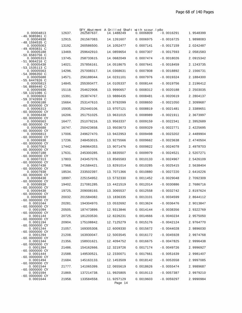
SFY_Abutment A Drilled Shaft with scour.lp8o 0.00004813 12637. 262587637. 14.1488249 0.0006809 -0.0016291 1.9548399 -46.9085961 C 0.00004938 12915. 261567083. 14.1261607 0.0006975 -0.0016725 1.9898083 -48.1594535 C 0.00005063 13192. 260586500. 14.1052477 0.0007141 -0.0017159 2.0242487 -49.4093831 C 0.00005188 13469. 259642910. 14.0859654 0.0007307 -0.0017593 2.0581583 -50.6583756 C 0.00005313 13745. 258733615. 14.0682049 0.0007474 -0.0018026 2.0915342 -51.9064216 C 0.00005438 14021. 257856161. 14.0518675 0.0007641 -0.0018459 2.1243735 -53.1535113 C 0.00005563 14296. 257008317. 14.0368631 0.0007808 -0.0018892 2.1566731 -54.3996350 C 0.00005688 14571. 256188044. 14.0231101 0.0007976 -0.0019324 2.1884300 -55.6447826 C 0.00005813 14845. 255393477. 14.0105337 0.0008144 -0.0019756 2.2196412 -56.8889440 C 0.00005938 15118. 254622908. 13.9990657 0.0008312 -0.0020188 2.2503035 -58.1321086 C 0.00006063 15391. 253874767. 13.9886435 0.0008481 -0.0020619 2.2804137 -59.3742659 C 0.00006188 15664. 253147610. 13.9792099 0.0008650 -0.0021050 2.3099687 -60.0000000 CY 0.00006313 15935. 252440106. 13.9707121 0.0008819 -0.0021481 2.3389651 -60.0000000 CY 0.00006438 16206. 251751025. 13.9631015 0.0008989 -0.0021911 2.3673997 -60.0000000 CY 0.00006563 16477. 251079216. 13.9563337 0.0009159 -0.0022341 2.3952689 -60.0000000 CY 0.00006688 16747. 250423658. 13.9503673 0.0009329 -0.0022771 2.4225695 -60.0000000 CY 0.00006813 17006. 249627470. 13.9422953 0.0009498 -0.0023202 2.4489904 -60.0000000 CY 0.00006938 17236. 248453015. 13.9275566 0.0009662 -0.0023638 2.4740504 -60.0000000 CY 0.00007063 17442. 246964353. 13.9071476 0.0009822 -0.0024078 2.4978703 -60.0000000 CY 0.00007188 17631. 245300285. 13.8835507 0.0009979 -0.0024521 2.5207271 -60.0000000 CY 0.00007313 17803. 243457076. 13.8565583 0.0010133 -0.0024967 2.5426109 -60.0000000 CY 0.00007438 17968. 241584421. 13.8291014 0.0010285 -0.0025415 2.5638404 -60.0000000 CY 0.00007938 18534. 233502397. 13.7071366 0.0010880 -0.0027220 2.6416226 -60.0000000 CY 0.00008438 18997. 225154952. 13.5732330 0.0011452 -0.0029048 2.7092309 -60.0000000 CY 0.00008938 19402. 217081285. 13.4421519 0.0012014 -0.0030886 2.7686716 -60.0000000 CY 0.00009438 19725. 209008193. 13.3065537 0.0012558 -0.0032742 2.8197624 -60.0000000 CY 0.00009938 20032. 201584082. 13.1836335 0.0013101 -0.0034599 2.8644112 -60.0000000 CY 0.0001044 20281. 194304970. 13.0532692 0.0013624 -0.0036476 2.9013847 -60.0000000 CY 0.0001094 20505. 187473899. 12.9313846 0.0014144 -0.0038356 2.9322769 -60.0000000 CY 0.0001144 20725. 181203530. 12.8226231 0.0014666 -0.0040234 2.9575050 -60.0000000 CY 0.0001194 20904. 175108842. 12.7125279 0.0015176 -0.0042124 2.9764770 -60.0000000 CY 0.0001244 21057. 169305308. 12.6009330 0.0015672 -0.0044028 2.9896030 -60.0000000 CY 0.0001294 21208. 163930047. 12.5003545 0.0016172 -0.0045928 2.9974768 -60.0000000 CY 0.0001344 21356. 158931621. 12.4094752 0.0016675 -0.0047825 2.9996438 -60.0000000 CY 0.0001394 21486. 154162666. 12.3219726 0.0017174 -0.0049726 2.9996927 -60.0000000 CY 0.0001444 21588. 149530521. 12.2330071 0.0017661 -0.0051639 2.9981407 -60.0000000 CY 0.0001494 21684. 145163133. 12.1453509 0.0018142 -0.0053558 2.9997085 -60.0000000 CY 0.0001544 21777. 141065399. 12.0655619 0.0018626 -0.0055474 2.9989687 -60.0000000 CY 0.0001594 21869. 137214738. 11.9925805 0.0019113 -0.0057387 2.9979210 -60.0000000 CY 0.0001644 21958. 133584558. 11.9257129 0.0019603 -0.0059297 2.9990984
Page 14
Page 68 of 140 Pages

SFY_Abutment A Drilled Shaft with scour.lp8o-60.0000000 CY 0.0001694 22040. 130125060. 11.8617992 0.0020091 -0.0061209 2.9979886 -60.0000000 CY 0.0001744 22108. 126786460. 11.7980040 0.0020573 -0.0063127 2.9984914 -60.0000000 CY 0.0001794 22165. 123566679. 11.7322327 0.0021045 -0.0065055 2.9999922 -60.0000000 CY 0.0001844 22218. 120503917. 11.6680067 0.0021513 -0.0066987 2.9962805 60.0000000 CY 0.0001894 22270. 117599306. 11.6081478 0.0021983 -0.0068917 2.9992333 60.0000000 CY 0.0001944 22322. 114840362. 11.5523809 0.0022455 -0.0070845 2.9988606 60.0000000 CY 0.0001994 22373. 112215015. 11.5006209 0.0022929 -0.0072771 2.9961694 60.0000000 CY 0.0002044 22423. 109715537. 11.4521704 0.0023405 -0.0074695 2.9990694 60.0000000 CY 0.0002094 22473. 107332007. 11.4067379 0.0023883 -0.0076617 2.9997970 60.0000000 CY 0.0002144 22521. 105053276. 11.3642926 0.0024362 -0.0078538 2.9941739 60.0000000 CY 0.0002194 22564. 102857292. 11.3222149 0.0024838 -0.0080462 2.9977439 60.0000000 CY 0.0002244 22603. 100737517. 11.2803252 0.0025310 -0.0082390 2.9996363 60.0000000 CY 0.0002294 22635. 98680649. 11.2340315 0.0025768 -0.0084332 2.9984634 60.0000000 CY 0.0002344 22663. 96694653. 11.1884497 0.0026223 -0.0086277 2.9932525 60.0000000 CY 0.0002394 22690. 94789278. 11.1449819 0.0026678 -0.0088222 2.9963116 60.0000000 CY 0.0002444 22717. 92959985. 11.1035603 0.0027134 -0.0090166 2.9986638 60.0000000 CY 0.0002494 22744. 91203200. 11.0642097 0.0027591 -0.0092109 2.9998495 60.0000000 CY 0.0002544 22770. 89514097. 11.0269915 0.0028050 -0.0094050 2.9976149 60.0000000 CY 0.0002594 22796. 87888941. 10.9917239 0.0028510 -0.0095990 2.9927986 60.0000000 CY 0.0002644 22822. 86324234. 10.9582184 0.0028971 -0.0097929 2.9946585 60.0000000 CY 0.0002694 22847. 84813337. 10.9272159 0.0029435 -0.0099865 2.9974432 60.0000000 CY 0.0002744 22871. 83356895. 10.8976667 0.0029900 -0.0101800 2.9992188 60.0000000 CY 0.0003044 22997. 75554596. 10.7511749 0.0032724 -0.0113376 2.9980806 60.0000000 CYT 0.0003344 23055. 68950984. 10.6264980 0.0035532 -0.0124968 2.9915740 60.0000000 CYT 0.0003644 23085. 63355592. 10.5310526 0.0038373 -0.0136527 2.9963767 60.0000000 CYT
Axial Thrust Force = 167.644 kips
Bending Bending Bending Depth to Max Comp Max Tens Max Conc Max Steel Run Curvature Moment Stiffness N Axis Strain Strain Stress Stress Msg rad/in. in-kip kip-in2 in in/in in/in ksi ksi ------------- ------------- ------------- ------------- ------------- ------------- ------------- ------------- --- 6.25000E-07 652.5444172 1044071067. 61.9113784 0.00003869 0.00000869 0.1399027 1.1177937 0.00000125 1305. 1044008708. 42.9939275 0.00005374 -0.00000626 0.1930811 1.5498299 0.00000188 1956. 1043178168. 36.6997234 0.00006881 -0.00002119 0.2458371 1.9824975 0.00000250 2604. 1041517578. 33.5560096 0.00008389 -0.00003611 0.2981222 2.4154107 0.00000313 3248. 1039401824. 31.6710467 0.00009897 -0.00005103 0.3499198 2.8484386 0.00000375 3889. 1037030942. 30.4150269 0.0001141 -0.00006594 0.4012241 3.2815342 0.00000438 4526. 1034505942. 29.5182410 0.0001291 -0.00008086 0.4520325 3.7146768 0.00000500 5159. 1031881550. 28.8459055 0.0001442 -0.00009577 0.5023435 4.1478563
Page 15
Page 69 of 140 Pages

SFY_Abutment A Drilled Shaft with scour.lp8o 0.00000563 5789. 1029189554. 28.3231682 0.0001593 -0.0001107 0.5521563 4.5810668 0.00000625 5789. 926270599. 22.4167204 0.0001401 -0.0001599 0.4874915 -4.5934694 C 0.00000688 5789. 842064181. 21.7174044 0.0001493 -0.0001807 0.5178283 -5.1922426 C 0.00000750 5789. 771892166. 21.1151502 0.0001584 -0.0002016 0.5474953 -5.7952548 C 0.00000813 5789. 712515845. 20.5912037 0.0001673 -0.0002227 0.5765992 -6.4016476 C 0.00000875 5789. 661621856. 20.1306008 0.0001761 -0.0002439 0.6051989 -7.0109600 C 0.00000938 5789. 617513733. 19.7223105 0.0001849 -0.0002651 0.6333506 -7.6227468 C 0.00001000 5789. 578919124. 19.3582776 0.0001936 -0.0002864 0.6611160 -8.2364995 C 0.00001063 5789. 544865058. 19.0305220 0.0002022 -0.0003078 0.6884932 -8.8522704 C 0.00001125 5789. 514594777. 18.7332442 0.0002107 -0.0003293 0.7154950 -9.4699791 C 0.00001188 5789. 487510842. 18.4655082 0.0002193 -0.0003507 0.7422720 -10.0882906 C 0.00001250 5789. 463135299. 18.2181360 0.0002277 -0.0003723 0.7686373 -10.7089257 C 0.00001313 5789. 441081238. 17.9946446 0.0002362 -0.0003938 0.7948611 -11.3294384 C 0.00001375 5789. 421032090. 17.7857660 0.0002446 -0.0004154 0.8206843 -11.9522258 C 0.00001438 5789. 402726347. 17.5954857 0.0002529 -0.0004371 0.8463748 -12.5748319 C 0.00001500 5789. 385946083. 17.4183842 0.0002613 -0.0004587 0.8717888 -13.1986028 C 0.00001563 5789. 370508240. 17.2536688 0.0002696 -0.0004804 0.8969663 -13.8231813 C 0.00001625 5789. 356257923. 17.1020062 0.0002779 -0.0005021 0.9220130 -14.4475795 C 0.00001688 5866. 347628491. 16.9594114 0.0002862 -0.0005238 0.9467986 -15.0730380 C 0.00001750 6013. 343590627. 16.8254880 0.0002944 -0.0005456 0.9713554 -15.6992648 C 0.00001813 6159. 339824170. 16.7011430 0.0003027 -0.0005673 0.9957832 -16.3253117 C 0.00001875 6306. 336301956. 16.5854194 0.0003110 -0.0005890 1.0200815 -16.9511781 C 0.00001938 6451. 332977550. 16.4746662 0.0003192 -0.0006108 1.0440882 -17.5784469 C 0.00002000 6597. 329848075. 16.3703338 0.0003274 -0.0006326 1.0679190 -18.2060063 C 0.00002063 6742. 326902179. 16.2726274 0.0003356 -0.0006544 1.0916219 -18.8333847 C 0.00002125 6888. 324123643. 16.1809634 0.0003438 -0.0006762 1.1151969 -19.4605813 C 0.00002188 7033. 321498103. 16.0948247 0.0003521 -0.0006979 1.1386435 -20.0875955 C 0.00002250 7177. 318996899. 16.0114131 0.0003603 -0.0007197 1.1618101 -20.7159529 C 0.00002313 7322. 316622191. 15.9322896 0.0003684 -0.0007416 1.1848172 -21.3444582 C 0.00002375 7466. 314367257. 15.8575979 0.0003766 -0.0007634 1.2076974 -21.9727794 C 0.00002438 7610. 312222866. 15.7869980 0.0003848 -0.0007852 1.2304504 -22.6009157 C 0.00002563 7898. 308233291. 15.6568799 0.0004012 -0.0008288 1.2755740 -23.8566310 C 0.00002688 8186. 304584039. 15.5376207 0.0004176 -0.0008724 1.3200228 -25.1133168 C 0.00002813 8472. 301231184. 15.4279996 0.0004339 -0.0009161 1.3638178 -26.3707878 C 0.00002938 8758. 298146829. 15.3286042 0.0004503 -0.0009597 1.4071049 -27.6274952 C 0.00003063 9044. 295297980. 15.2381892 0.0004667 -0.0010033 1.4498817 -28.8834332 C 0.00003188 9328. 292656816. 15.1557046 0.0004831 -0.0010469 1.4921459 -30.1385955 C 0.00003313 9613. 290193374. 15.0787406 0.0004995 -0.0010905 1.5337661 -31.3944348 C 0.00003438 9896. 287889290. 15.0069146 0.0005159 -0.0011341 1.5747638 -32.6507319 C 0.00003563 10179. 285732829. 14.9409089 0.0005323 -0.0011777 1.6152494
Page 16
Page 70 of 140 Pages

SFY_Abutment A Drilled Shaft with scour.lp8o-33.9062233 C 0.00003688 10462. 283708873. 14.8801380 0.0005487 -0.0012213 1.6552207 -35.1609023 C 0.00003813 10744. 281804288. 14.8240933 0.0005652 -0.0012648 1.6946751 -36.4147617 C 0.00003938 11025. 280007606. 14.7723309 0.0005817 -0.0013083 1.7336100 -37.6677945 C 0.00004063 11306. 278308767. 14.7244616 0.0005982 -0.0013518 1.7720230 -38.9199935 C 0.00004188 11587. 276698912. 14.6801429 0.0006147 -0.0013953 1.8099116 -40.1713514 C 0.00004313 11867. 275170108. 14.6390351 0.0006313 -0.0014387 1.8472694 -41.4219066 C 0.00004438 12146. 273711534. 14.5994293 0.0006478 -0.0014822 1.8839506 -42.6735093 C 0.00004563 12425. 272321396. 14.5626618 0.0006644 -0.0015256 1.9201058 -43.9242280 C 0.00004688 12703. 270994125. 14.5285117 0.0006810 -0.0015690 1.9557325 -45.1740543 C 0.00004813 12981. 269724732. 14.4967812 0.0006977 -0.0016123 1.9908277 -46.4229796 C 0.00004938 13258. 268508731. 14.4672926 0.0007143 -0.0016557 2.0253888 -47.6709953 C 0.00005063 13534. 267342076. 14.4398858 0.0007310 -0.0016990 2.0594128 -48.9180925 C 0.00005188 13810. 266221111. 14.4144163 0.0007477 -0.0017423 2.0928969 -50.1642623 C 0.00005313 14086. 265142523. 14.3907533 0.0007645 -0.0017855 2.1258382 -51.4094955 C 0.00005438 14361. 264103302. 14.3687781 0.0007813 -0.0018287 2.1582337 -52.6537828 C 0.00005563 14635. 263100705. 14.3483829 0.0007981 -0.0018719 2.1900805 -53.8971147 C 0.00005688 14909. 262132232. 14.3294693 0.0008150 -0.0019150 2.2213754 -55.1394814 C 0.00005813 15182. 261195594. 14.3119476 0.0008319 -0.0019581 2.2521154 -56.3808731 C 0.00005938 15455. 260288696. 14.2957358 0.0008488 -0.0020012 2.2822973 -57.6212798 C 0.00006063 15727. 259409611. 14.2807586 0.0008658 -0.0020442 2.3119180 -58.8606911 C 0.00006188 15998. 258556568. 14.2669470 0.0008828 -0.0020872 2.3409742 -60.0000000 CY 0.00006313 16269. 257727936. 14.2542377 0.0008998 -0.0021302 2.3694626 -60.0000000 CY 0.00006438 16539. 256922207. 14.2425722 0.0009169 -0.0021731 2.3973799 -60.0000000 CY 0.00006563 16809. 256137987. 14.2318967 0.0009340 -0.0022160 2.4247227 -60.0000000 CY 0.00006688 17078. 255373986. 14.2221615 0.0009511 -0.0022589 2.4514875 -60.0000000 CY 0.00006813 17343. 254574267. 14.2123481 0.0009682 -0.0023018 2.4775693 -60.0000000 CY 0.00006938 17588. 253523425. 14.1985136 0.0009850 -0.0023450 2.5025621 -60.0000000 CY 0.00007063 17804. 252086873. 14.1780193 0.0010013 -0.0023887 2.5262055 -60.0000000 CY 0.00007188 18001. 250445776. 14.1537708 0.0010173 -0.0024327 2.5488160 -60.0000000 CY 0.00007313 18180. 248614022. 14.1251923 0.0010329 -0.0024771 2.5703496 -60.0000000 CY 0.00007438 18345. 246653564. 14.0941870 0.0010483 -0.0025217 2.5910150 -60.0000000 CY 0.00007938 18925. 238430853. 13.9629261 0.0011083 -0.0027017 2.6669338 -60.0000000 CY 0.00008438 19404. 229975096. 13.8262384 0.0011666 -0.0028834 2.7331289 -60.0000000 CY 0.00008938 19814. 221690423. 13.6919017 0.0012237 -0.0030663 2.7908777 -60.0000000 CY 0.00009438 20146. 213467721. 13.5492532 0.0012787 -0.0032513 2.8397933 -60.0000000 CY 0.00009938 20453. 205819628. 13.4179184 0.0013334 -0.0034366 2.8819816 -60.0000000 CY 0.0001044 20716. 198474251. 13.2899575 0.0013871 -0.0036229 2.9171499 -60.0000000 CY 0.0001094 20940. 191451090. 13.1646060 0.0014399 -0.0038101 2.9456224 -60.0000000 CY 0.0001144 21159. 184999126. 13.0483125 0.0014924 -0.0039976 2.9680400 -60.0000000 CY
Page 17
Page 71 of 140 Pages
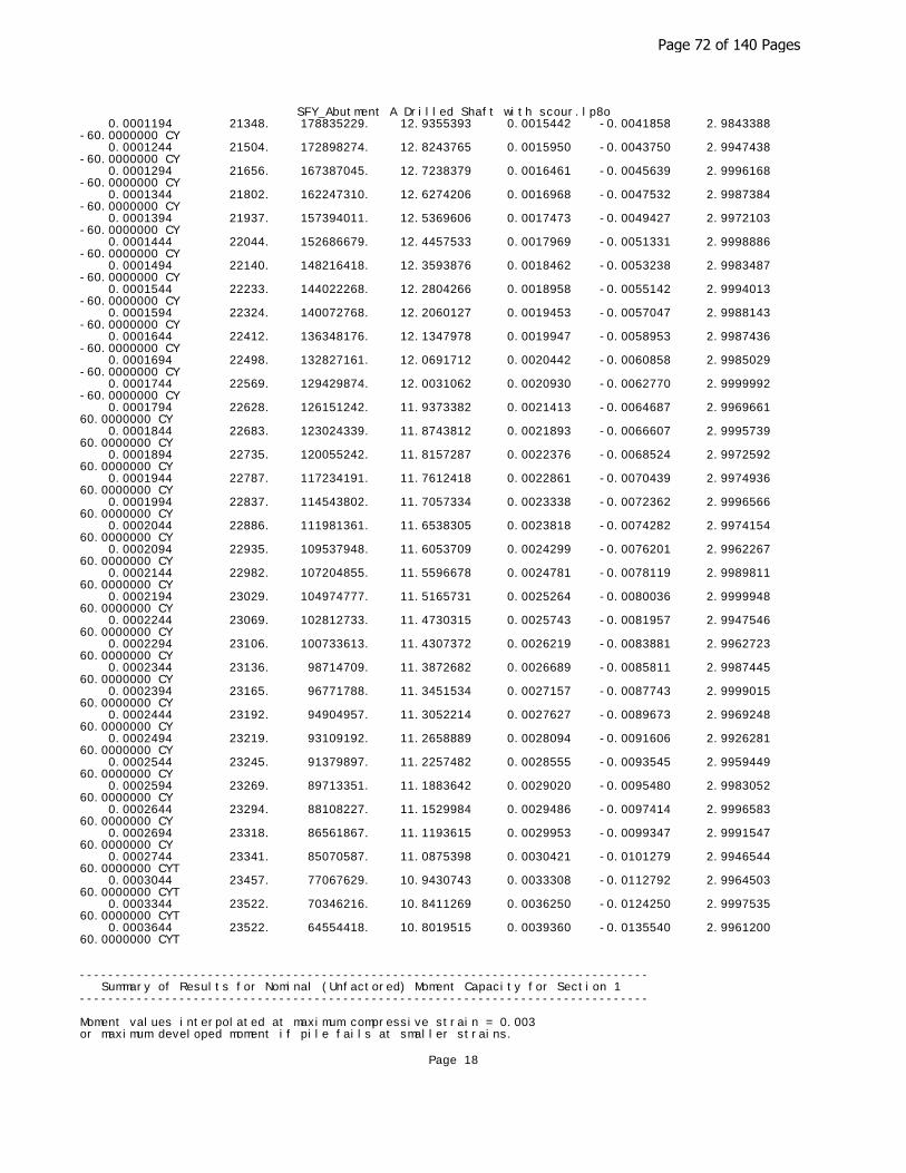
SFY_Abutment A Drilled Shaft with scour.lp8o 0.0001194 21348. 178835229. 12.9355393 0.0015442 -0.0041858 2.9843388 -60.0000000 CY 0.0001244 21504. 172898274. 12.8243765 0.0015950 -0.0043750 2.9947438 -60.0000000 CY 0.0001294 21656. 167387045. 12.7238379 0.0016461 -0.0045639 2.9996168 -60.0000000 CY 0.0001344 21802. 162247310. 12.6274206 0.0016968 -0.0047532 2.9987384 -60.0000000 CY 0.0001394 21937. 157394011. 12.5369606 0.0017473 -0.0049427 2.9972103 -60.0000000 CY 0.0001444 22044. 152686679. 12.4457533 0.0017969 -0.0051331 2.9998886 -60.0000000 CY 0.0001494 22140. 148216418. 12.3593876 0.0018462 -0.0053238 2.9983487 -60.0000000 CY 0.0001544 22233. 144022268. 12.2804266 0.0018958 -0.0055142 2.9994013 -60.0000000 CY 0.0001594 22324. 140072768. 12.2060127 0.0019453 -0.0057047 2.9988143 -60.0000000 CY 0.0001644 22412. 136348176. 12.1347978 0.0019947 -0.0058953 2.9987436 -60.0000000 CY 0.0001694 22498. 132827161. 12.0691712 0.0020442 -0.0060858 2.9985029 -60.0000000 CY 0.0001744 22569. 129429874. 12.0031062 0.0020930 -0.0062770 2.9999992 -60.0000000 CY 0.0001794 22628. 126151242. 11.9373382 0.0021413 -0.0064687 2.9969661 60.0000000 CY 0.0001844 22683. 123024339. 11.8743812 0.0021893 -0.0066607 2.9995739 60.0000000 CY 0.0001894 22735. 120055242. 11.8157287 0.0022376 -0.0068524 2.9972592 60.0000000 CY 0.0001944 22787. 117234191. 11.7612418 0.0022861 -0.0070439 2.9974936 60.0000000 CY 0.0001994 22837. 114543802. 11.7057334 0.0023338 -0.0072362 2.9996566 60.0000000 CY 0.0002044 22886. 111981361. 11.6538305 0.0023818 -0.0074282 2.9974154 60.0000000 CY 0.0002094 22935. 109537948. 11.6053709 0.0024299 -0.0076201 2.9962267 60.0000000 CY 0.0002144 22982. 107204855. 11.5596678 0.0024781 -0.0078119 2.9989811 60.0000000 CY 0.0002194 23029. 104974777. 11.5165731 0.0025264 -0.0080036 2.9999948 60.0000000 CY 0.0002244 23069. 102812733. 11.4730315 0.0025743 -0.0081957 2.9947546 60.0000000 CY 0.0002294 23106. 100733613. 11.4307372 0.0026219 -0.0083881 2.9962723 60.0000000 CY 0.0002344 23136. 98714709. 11.3872682 0.0026689 -0.0085811 2.9987445 60.0000000 CY 0.0002394 23165. 96771788. 11.3451534 0.0027157 -0.0087743 2.9999015 60.0000000 CY 0.0002444 23192. 94904957. 11.3052214 0.0027627 -0.0089673 2.9969248 60.0000000 CY 0.0002494 23219. 93109192. 11.2658889 0.0028094 -0.0091606 2.9926281 60.0000000 CY 0.0002544 23245. 91379897. 11.2257482 0.0028555 -0.0093545 2.9959449 60.0000000 CY 0.0002594 23269. 89713351. 11.1883642 0.0029020 -0.0095480 2.9983052 60.0000000 CY 0.0002644 23294. 88108227. 11.1529984 0.0029486 -0.0097414 2.9996583 60.0000000 CY 0.0002694 23318. 86561867. 11.1193615 0.0029953 -0.0099347 2.9991547 60.0000000 CY 0.0002744 23341. 85070587. 11.0875398 0.0030421 -0.0101279 2.9946544 60.0000000 CYT 0.0003044 23457. 77067629. 10.9430743 0.0033308 -0.0112792 2.9964503 60.0000000 CYT 0.0003344 23522. 70346216. 10.8411269 0.0036250 -0.0124250 2.9997535 60.0000000 CYT 0.0003644 23522. 64554418. 10.8019515 0.0039360 -0.0135540 2.9961200 60.0000000 CYT
-------------------------------------------------------------------------------- Summary of Results for Nominal (Unfactored) Moment Capacity for Section 1--------------------------------------------------------------------------------
Moment values interpolated at maximum compressive strain = 0.003or maximum developed moment if pile fails at smaller strains.
Page 18
Page 72 of 140 Pages

SFY_Abutment A Drilled Shaft with scour.lp8o Load Axial Thrust Nominal Mom. Cap. Max. Comp. No. kips in-kip Strain ---- ---------------- ------------------ ------------ 1 96.931 22332.755 0.00300000 2 124.321 22718.471 0.00300000 3 135.553 22875.486 0.00300000 4 167.644 23319.985 0.00300000
Note that the values of moment capacity in the table above are not factored by a strength reduction factor (phi-factor).
In ACI 318, the value of the strength reduction factor depends on whether the transverse reinforcing steel bars are tied hoops (0.65) or spirals (0.70).
The above values should be multiplied by the appropriate strength reduction factor to compute ultimate moment capacity according to ACI 318, Section 9.3.2.2 or the value required by the design standard being followed.
The following table presents factored moment capacities and corresponding bending stiffnesses computed for common resistance factor values used for reinforced concrete sections.
Axial Resist. Nominal Ult. (Fac) Ult. (Fac) Bend. Stiff.Load Factor Moment Cap Ax. Thrust Moment Cap at Ult Mom No. for Moment in-kips kips in-kips kip-in^2 ----- ------------ ------------ ------------ ------------ ------------ 1 0.65 22333. 63.005148 14516. 248187538. 2 0.65 22718. 80.808647 14767. 253245772. 3 0.65 22875. 88.109447 14869. 255324956. 4 0.65 23320. 108.968596 15158. 261277884. 1 0.70 22333. 67.851699 15633. 245830340. 2 0.70 22718. 87.024699 15903. 250378847. 3 0.70 22875. 94.887098 16013. 252243035. 4 0.70 23320. 117.350798 16324. 257564242. 1 0.75 22333. 72.698250 16750. 242541960. 2 0.75 22718. 93.240750 17039. 247031166. 3 0.75 22875. 101.664750 17157. 248859586. 4 0.75 23320. 125.733000 17490. 253944074.
-------------------------------------------------------------------------------- Computed Values of Pile Loading and Deflection for Lateral Loading for Load Case Number 1--------------------------------------------------------------------------------
Pile-head conditions are Shear and Moment (Loading Type 1)
Shear force at pile head = 23269.0 lbsApplied moment at pile head = 1112698.0 in-lbsAxial thrust load on pile head = 167644.0 lbs
Depth Deflect. Bending Shear Slope Total Bending Soil Res. Soil Spr. Distrib. X y Moment Force S Stress Stiffness p Es*h Lat. Load feet inches in-lbs lbs radians psi* in-lb^2 lb/inch lb/inch lb/inch ---------- ---------- ---------- ---------- ---------- ---------- ---------- ---------- ---------- ---------- 0.00 0.2574 1112698. 23269. -0.00131 0.00 1.04E+12 0.00 0.00 0.00 0.4348 0.2506 1235246. 23269. -0.00131 0.00 1.04E+12 0.00 0.00 0.00 0.8696 0.2438 1357788. 23269. -0.00130 0.00 1.04E+12 0.00 0.00 0.00 1.3043 0.2370 1480325. 23269. -0.00129 0.00 1.04E+12 0.00 0.00 0.00 1.7391 0.2303 1602855. 23269. -0.00128 0.00 1.04E+12 0.00 0.00 0.00 2.1739 0.2236 1725378. 23269. -0.00128 0.00 1.04E+12 0.00 0.00 0.00 2.6087 0.2170 1847894. 23269. -0.00127 0.00 1.04E+12 0.00 0.00 0.00 3.0435 0.2104 1970401. 23269. -0.00126 0.00 1.04E+12 0.00 0.00 0.00
Page 19
Page 73 of 140 Pages
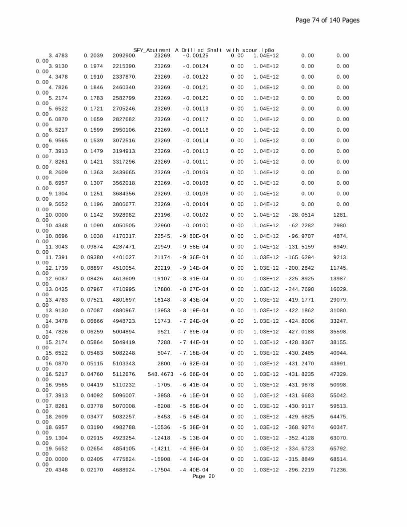
SFY_Abutment A Drilled Shaft with scour.lp8o 3.4783 0.2039 2092900. 23269. -0.00125 0.00 1.04E+12 0.00 0.00 0.00 3.9130 0.1974 2215390. 23269. -0.00124 0.00 1.04E+12 0.00 0.00 0.00 4.3478 0.1910 2337870. 23269. -0.00122 0.00 1.04E+12 0.00 0.00 0.00 4.7826 0.1846 2460340. 23269. -0.00121 0.00 1.04E+12 0.00 0.00 0.00 5.2174 0.1783 2582799. 23269. -0.00120 0.00 1.04E+12 0.00 0.00 0.00 5.6522 0.1721 2705246. 23269. -0.00119 0.00 1.04E+12 0.00 0.00 0.00 6.0870 0.1659 2827682. 23269. -0.00117 0.00 1.04E+12 0.00 0.00 0.00 6.5217 0.1599 2950106. 23269. -0.00116 0.00 1.04E+12 0.00 0.00 0.00 6.9565 0.1539 3072516. 23269. -0.00114 0.00 1.04E+12 0.00 0.00 0.00 7.3913 0.1479 3194913. 23269. -0.00113 0.00 1.04E+12 0.00 0.00 0.00 7.8261 0.1421 3317296. 23269. -0.00111 0.00 1.04E+12 0.00 0.00 0.00 8.2609 0.1363 3439665. 23269. -0.00109 0.00 1.04E+12 0.00 0.00 0.00 8.6957 0.1307 3562018. 23269. -0.00108 0.00 1.04E+12 0.00 0.00 0.00 9.1304 0.1251 3684356. 23269. -0.00106 0.00 1.04E+12 0.00 0.00 0.00 9.5652 0.1196 3806677. 23269. -0.00104 0.00 1.04E+12 0.00 0.00 0.00 10.0000 0.1142 3928982. 23196. -0.00102 0.00 1.04E+12 -28.0514 1281. 0.00 10.4348 0.1090 4050505. 22960. -0.00100 0.00 1.04E+12 -62.2282 2980. 0.00 10.8696 0.1038 4170317. 22545. -9.80E-04 0.00 1.04E+12 -96.9707 4874. 0.00 11.3043 0.09874 4287471. 21949. -9.58E-04 0.00 1.04E+12 -131.5159 6949. 0.00 11.7391 0.09380 4401027. 21174. -9.36E-04 0.00 1.03E+12 -165.6294 9213. 0.00 12.1739 0.08897 4510054. 20219. -9.14E-04 0.00 1.03E+12 -200.2842 11745. 0.00 12.6087 0.08426 4613609. 19107. -8.91E-04 0.00 1.03E+12 -225.8925 13987. 0.00 13.0435 0.07967 4710995. 17880. -8.67E-04 0.00 1.03E+12 -244.7698 16029. 0.00 13.4783 0.07521 4801697. 16148. -8.43E-04 0.00 1.03E+12 -419.1771 29079. 0.00 13.9130 0.07087 4880967. 13953. -8.19E-04 0.00 1.03E+12 -422.1862 31080. 0.00 14.3478 0.06666 4948723. 11743. -7.94E-04 0.00 1.03E+12 -424.8006 33247. 0.00 14.7826 0.06259 5004894. 9521. -7.69E-04 0.00 1.03E+12 -427.0188 35598. 0.00 15.2174 0.05864 5049419. 7288. -7.44E-04 0.00 1.03E+12 -428.8367 38155. 0.00 15.6522 0.05483 5082248. 5047. -7.18E-04 0.00 1.03E+12 -430.2485 40944. 0.00 16.0870 0.05115 5103343. 2800. -6.92E-04 0.00 1.03E+12 -431.2470 43991. 0.00 16.5217 0.04760 5112676. 548.4673 -6.66E-04 0.00 1.03E+12 -431.8235 47329. 0.00 16.9565 0.04419 5110232. -1705. -6.41E-04 0.00 1.03E+12 -431.9678 50998. 0.00 17.3913 0.04092 5096007. -3958. -6.15E-04 0.00 1.03E+12 -431.6683 55042. 0.00 17.8261 0.03778 5070008. -6208. -5.89E-04 0.00 1.03E+12 -430.9117 59513. 0.00 18.2609 0.03477 5032257. -8453. -5.64E-04 0.00 1.03E+12 -429.6825 64475. 0.00 18.6957 0.03190 4982788. -10536. -5.38E-04 0.00 1.03E+12 -368.9274 60347. 0.00 19.1304 0.02915 4923254. -12418. -5.13E-04 0.00 1.03E+12 -352.4128 63070. 0.00 19.5652 0.02654 4854105. -14211. -4.89E-04 0.00 1.03E+12 -334.6723 65792. 0.00 20.0000 0.02405 4775824. -15908. -4.64E-04 0.00 1.03E+12 -315.8849 68514. 0.00 20.4348 0.02170 4688924. -17504. -4.40E-04 0.00 1.03E+12 -296.2219 71236.
Page 20
Page 74 of 140 Pages

SFY_Abutment A Drilled Shaft with scour.lp8o0.00 20.8696 0.01946 4593939. -18997. -4.17E-04 0.00 1.03E+12 -275.8472 73958. 0.00 21.3043 0.01734 4491425. -20381. -3.94E-04 0.00 1.03E+12 -254.9166 76680. 0.00 21.7391 0.01535 4381952. -21656. -3.72E-04 0.00 1.04E+12 -233.5774 79402. 0.00 22.1739 0.01347 4266102. -22818. -3.50E-04 0.00 1.04E+12 -211.9687 82124. 0.00 22.6087 0.01170 4144463. -23867. -3.29E-04 0.00 1.04E+12 -190.2205 84846. 0.00 23.0435 0.01004 4017627. -24803. -3.08E-04 0.00 1.04E+12 -168.4539 87569. 0.00 23.4783 0.00848 3886188. -25625. -2.88E-04 0.00 1.04E+12 -146.7806 90291. 0.00 23.9130 0.00703 3750737. -26335. -2.69E-04 0.00 1.04E+12 -125.3034 93013. 0.00 24.3478 0.00567 3611858. -26934. -2.51E-04 0.00 1.04E+12 -104.1157 95735. 0.00 24.7826 0.00441 3470130. -27422. -2.33E-04 0.00 1.04E+12 -83.3022 98457. 0.00 25.2174 0.00325 3326118. -27804. -2.16E-04 0.00 1.04E+12 -62.9381 101179. 0.00 25.6522 0.00216 3180379. -28081. -1.99E-04 0.00 1.04E+12 -43.0895 103901. 0.00 26.0870 0.00117 3033452. -28255. -1.84E-04 0.00 1.04E+12 -23.8141 106623. 0.00 26.5217 2.46E-04 2885864. -28331. -1.69E-04 0.00 1.04E+12 -5.1608 109346. 0.00 26.9565 -5.97E-04 2738123. -28311. -1.55E-04 0.00 1.04E+12 12.8297 112068. 0.00 27.3913 -0.00137 2590719. -28199. -1.41E-04 0.00 1.04E+12 30.1252 114790. 0.00 27.8261 -0.00207 2444124. -27998. -1.29E-04 0.00 1.04E+12 46.7012 117512. 0.00 28.2609 -0.00271 2298790. -27713. -1.17E-04 0.00 1.04E+12 62.5404 120234. 0.00 28.6957 -0.00329 2155147. -27348. -1.06E-04 0.00 1.04E+12 77.6327 122956. 0.00 29.1304 -0.00382 2013609. -26905. -9.54E-05 0.00 1.04E+12 91.9752 125678. 0.00 29.5652 -0.00429 1874565. -26390. -8.57E-05 0.00 1.04E+12 105.5712 128400. 0.00 30.0000 -0.00471 1738387. -25805. -7.67E-05 0.00 1.04E+12 118.4299 131122. 0.00 30.4348 -0.00509 1605426. -25156. -6.83E-05 0.00 1.04E+12 130.5662 133845. 0.00 30.8696 -0.00542 1476011. -24445. -6.06E-05 0.00 1.04E+12 141.9999 136567. 0.00 31.3043 -0.00572 1350455. -23676. -5.35E-05 0.00 1.04E+12 152.7558 139289. 0.00 31.7391 -0.00598 1229052. -22853. -4.71E-05 0.00 1.04E+12 162.8630 142011. 0.00 32.1739 -0.00621 1112077. -21978. -4.12E-05 0.00 1.04E+12 172.3543 144733. 0.00 32.6087 -0.00641 999788. -21056. -3.60E-05 0.00 1.04E+12 181.2657 147455. 0.00 33.0435 -0.00659 892429. -20088. -3.12E-05 0.00 1.04E+12 189.6361 150177. 0.00 33.4783 -0.00674 790229. -19078. -2.70E-05 0.00 1.04E+12 197.5067 152899. 0.00 33.9130 -0.00687 693401. -18028. -2.33E-05 0.00 1.04E+12 204.9207 155622. 0.00 34.3478 -0.00698 602149. -16941. -2.01E-05 0.00 1.04E+12 211.9223 158344. 0.00 34.7826 -0.00708 516662. -15818. -1.73E-05 0.00 1.04E+12 218.5567 161066. 0.00 35.2174 -0.00716 437123. -14661. -1.49E-05 0.00 1.04E+12 224.8694 163788. 0.00 35.6522 -0.00724 363703. -13472. -1.29E-05 0.00 1.04E+12 230.9055 166510. 0.00 36.0870 -0.00730 296567. -12252. -1.12E-05 0.00 1.04E+12 236.7091 169232. 0.00 36.5217 -0.00735 235874. -11003. -9.92E-06 0.00 1.04E+12 242.3231 171954. 0.00 36.9565 -0.00740 181775. -9724. -8.87E-06 0.00 1.04E+12 247.7885 174676. 0.00 37.3913 -0.00745 134421. -8417. -8.08E-06 0.00 1.04E+12 253.1435 177398. 0.00
Page 21
Page 75 of 140 Pages

SFY_Abutment A Drilled Shaft with scour.lp8o 37.8261 -0.00749 93957. -7083. -7.51E-06 0.00 1.04E+12 258.4233 180121. 0.00 38.2609 -0.00752 60527. -5721. -7.13E-06 0.00 1.04E+12 263.6595 182843. 0.00 38.6957 -0.00756 34274. -4332. -6.89E-06 0.00 1.04E+12 268.8791 185565. 0.00 39.1304 -0.00760 15341. -2915. -6.77E-06 0.00 1.04E+12 274.1045 188287. 0.00 39.5652 -0.00763 3868. -1471. -6.72E-06 0.00 1.04E+12 279.3523 191009. 0.00 40.0000 -0.00767 0.00 0.00 -6.71E-06 0.00 1.04E+12 284.6330 96866. 0.00
* This analysis computed pile response using nonlinear moment-curvature rela- tionships. Values of total stress due to combined axial and bending stresses are computed only for elastic sections only and do not equal the actual stresses in concrete and steel. Stresses in concrete and steel may be inter- polated from the output for nonlinear bending properties relative to the magnitude of bending moment developed in the pile.
Output Summary for Load Case No. 1:
Pile-head deflection = 0.25742126 inchesComputed slope at pile head = -0.00131124 radiansMaximum bending moment = 5112676. inch-lbsMaximum shear force = -28331. lbsDepth of maximum bending moment = 16.52173913 feet below pile headDepth of maximum shear force = 26.52173913 feet below pile headNumber of iterations = 13Number of zero deflection points = 1
-------------------------------------------------------------------------------- Pile-head Deflection vs. Pile Length for Load Case 1--------------------------------------------------------------------------------
Boundary Condition Type 1, Shear and Moment
Shear = 23269. lbsMoment = 1112698. in-lbsAxial Load = 167644. lbs
Pile Pile Head Maximum Maximum Length Deflection Moment Shear feet inches ln-lbs lbs ------------ ------------ ------------ ------------ 40.00000 0.25742126 5112676. -28331. 38.00000 0.26407776 5113280. -30331. 36.00000 0.27432828 5078223. -33031. 34.00000 0.31013593 5054909. -37170. 32.00000 0.39279227 5031707. -42553. 30.00000 0.58840513 4973324. -48767. 28.00000 1.08718514 4941916. -56908. 26.00000 2.63874167 5011835. -68935.
-------------------------------------------------------------------------------- Computed Values of Pile Loading and Deflection for Lateral Loading for Load Case Number 2--------------------------------------------------------------------------------
Pile-head conditions are Shear and Moment (Loading Type 1)
Shear force at pile head = 28753.0 lbsApplied moment at pile head = 1558633.0 in-lbsAxial thrust load on pile head = 96931.0 lbs
Depth Deflect. Bending Shear Slope Total Bending Soil Res. Soil Spr. Distrib. X y Moment Force S Stress Stiffness p Es*h Lat. Load feet inches in-lbs lbs radians psi* in-lb^2 lb/inch lb/inch lb/inch ---------- ---------- ---------- ---------- ---------- ---------- ---------- ---------- ---------- ---------- 0.00 0.7693 1558633. 28753. -0.00393 0.00 1.05E+12 0.00 0.00
Page 22
Page 76 of 140 Pages
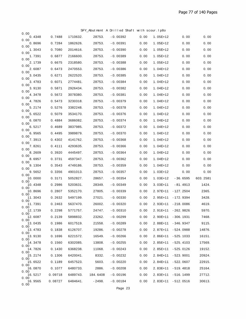
SFY_Abutment A Drilled Shaft with scour.lp8o0.00 0.4348 0.7488 1710632. 28753. -0.00392 0.00 1.05E+12 0.00 0.00 0.00 0.8696 0.7284 1862626. 28753. -0.00391 0.00 1.05E+12 0.00 0.00 0.00 1.3043 0.7080 2014616. 28753. -0.00390 0.00 1.05E+12 0.00 0.00 0.00 1.7391 0.6877 2166600. 28753. -0.00389 0.00 1.05E+12 0.00 0.00 0.00 2.1739 0.6675 2318580. 28753. -0.00388 0.00 1.05E+12 0.00 0.00 0.00 2.6087 0.6473 2470553. 28753. -0.00386 0.00 1.04E+12 0.00 0.00 0.00 3.0435 0.6271 2622520. 28753. -0.00385 0.00 1.04E+12 0.00 0.00 0.00 3.4783 0.6071 2774481. 28753. -0.00384 0.00 1.04E+12 0.00 0.00 0.00 3.9130 0.5871 2926434. 28753. -0.00382 0.00 1.04E+12 0.00 0.00 0.00 4.3478 0.5672 3078380. 28753. -0.00381 0.00 1.04E+12 0.00 0.00 0.00 4.7826 0.5473 3230318. 28753. -0.00379 0.00 1.04E+12 0.00 0.00 0.00 5.2174 0.5276 3382248. 28753. -0.00378 0.00 1.04E+12 0.00 0.00 0.00 5.6522 0.5079 3534170. 28753. -0.00376 0.00 1.04E+12 0.00 0.00 0.00 6.0870 0.4884 3686082. 28753. -0.00374 0.00 1.04E+12 0.00 0.00 0.00 6.5217 0.4689 3837985. 28753. -0.00372 0.00 1.04E+12 0.00 0.00 0.00 6.9565 0.4495 3989879. 28753. -0.00370 0.00 1.04E+12 0.00 0.00 0.00 7.3913 0.4302 4141762. 28753. -0.00368 0.00 1.04E+12 0.00 0.00 0.00 7.8261 0.4111 4293635. 28753. -0.00366 0.00 1.04E+12 0.00 0.00 0.00 8.2609 0.3920 4445497. 28753. -0.00364 0.00 1.04E+12 0.00 0.00 0.00 8.6957 0.3731 4597347. 28753. -0.00362 0.00 1.04E+12 0.00 0.00 0.00 9.1304 0.3543 4749186. 28753. -0.00359 0.00 1.04E+12 0.00 0.00 0.00 9.5652 0.3356 4901013. 28753. -0.00357 0.00 1.03E+12 0.00 0.00 0.00 10.0000 0.3171 5052827. 28657. -0.00354 0.00 1.03E+12 -36.6595 603.2581 0.00 10.4348 0.2986 5203631. 28349. -0.00349 0.00 3.03E+11 -81.4913 1424. 0.00 10.8696 0.2807 5352170. 27805. -0.00339 0.00 2.97E+11 -127.2504 2365. 0.00 11.3043 0.2632 5497199. 27021. -0.00330 0.00 2.95E+11 -172.9394 3428. 0.00 11.7391 0.2463 5637470. 26002. -0.00320 0.00 2.93E+11 -218.0086 4619. 0.00 12.1739 0.2298 5771757. 24747. -0.00310 0.00 2.91E+11 -262.9826 5970. 0.00 12.6087 0.2139 5898832. 23262. -0.00299 0.00 2.90E+11 -306.1931 7468. 0.00 13.0435 0.1986 6017519. 21558. -0.00289 0.00 2.88E+11 -346.9347 9115. 0.00 13.4783 0.1838 6126707. 19286. -0.00278 0.00 2.87E+11 -524.0988 14876. 0.00 13.9130 0.1696 6221572. 16549. -0.00266 0.00 2.86E+11 -525.1033 16151. 0.00 14.3478 0.1560 6302085. 13808. -0.00255 0.00 2.85E+11 -525.4103 17569. 0.00 14.7826 0.1430 6368238. 11068. -0.00243 0.00 2.85E+11 -525.0126 19152. 0.00 15.2174 0.1306 6420041. 8332. -0.00232 0.00 2.84E+11 -523.9001 20924. 0.00 15.6522 0.1189 6457523. 5603. -0.00220 0.00 2.84E+11 -522.0607 22915. 0.00 16.0870 0.1077 6480733. 2886. -0.00208 0.00 2.83E+11 -519.4818 25164. 0.00 16.5217 0.09718 6489743. 184.6408 -0.00196 0.00 2.83E+11 -516.1499 27712. 0.00 16.9565 0.08727 6484641. -2498. -0.00184 0.00 2.83E+11 -512.0516 30613. 0.00
Page 23
Page 77 of 140 Pages

SFY_Abutment A Drilled Shaft with scour.lp8o 17.3913 0.07798 6465541. -5156. -0.00172 0.00 2.84E+11 -507.1745 33932. 0.00 17.8261 0.06932 6432575. -7788. -0.00160 0.00 2.84E+11 -501.5072 37747. 0.00 18.2609 0.06127 6385897. -10388. -0.00148 0.00 2.84E+11 -495.0415 42155. 0.00 18.6957 0.05383 6325684. -13287. -0.00137 0.00 2.85E+11 -616.4248 59743. 0.00 19.1304 0.04700 6248633. -16377. -0.00125 0.00 2.86E+11 -568.1535 63070. 0.00 19.5652 0.04076 6156059. -19200. -0.00114 0.00 2.87E+11 -514.0198 65792. 0.00 20.0000 0.03511 6049435. -21744. -0.00103 0.00 2.88E+11 -461.0494 68514. 0.00 20.4348 0.03003 5930206. -24016. -9.21E-04 0.00 2.89E+11 -409.9860 71236. 0.00 20.8696 0.02550 5799763. -26029. -8.15E-04 0.00 2.91E+11 -361.5260 73958. 0.00 21.3043 0.02152 5659425. -27797. -7.13E-04 0.00 2.93E+11 -316.3176 76680. 0.00 21.7391 0.01807 5510427. -29340. -6.14E-04 0.00 2.95E+11 -274.9595 79402. 0.00 22.1739 0.01512 5353894. -30678. -5.18E-04 0.00 2.97E+11 -238.0003 82124. 0.00 22.6087 0.01266 5190835. -31836. -4.26E-04 0.00 3.04E+11 -205.9382 84846. 0.00 23.0435 0.01067 5022125. -32840. -3.69E-04 0.00 1.03E+12 -179.1211 87569. 0.00 23.4783 0.00881 4848527. -33705. -3.44E-04 0.00 1.03E+12 -152.5140 90291. 0.00 23.9130 0.00708 4670764. -34433. -3.20E-04 0.00 1.04E+12 -126.2406 93013. 0.00 24.3478 0.00547 4489553. -35024. -2.97E-04 0.00 1.04E+12 -100.4129 95735. 0.00 24.7826 0.00398 4305598. -35482. -2.75E-04 0.00 1.04E+12 -75.1316 98457. 0.00 25.2174 0.00260 4119586. -35810. -2.54E-04 0.00 1.04E+12 -50.4858 101179. 0.00 25.6522 0.00133 3932189. -36011. -2.34E-04 0.00 1.04E+12 -26.5535 103901. 0.00 26.0870 1.66E-04 3744060. -36089. -2.14E-04 0.00 1.04E+12 -3.4016 106623. 0.00 26.5217 -9.02E-04 3555829. -36048. -1.96E-04 0.00 1.04E+12 18.9134 109346. 0.00 26.9565 -0.00188 3368103. -35894. -1.79E-04 0.00 1.04E+12 40.3455 112068. 0.00 27.3913 -0.00277 3181467. -35630. -1.62E-04 0.00 1.04E+12 60.8587 114790. 0.00 27.8261 -0.00357 2996480. -35261. -1.47E-04 0.00 1.04E+12 80.4264 117512. 0.00 28.2609 -0.00430 2813674. -34793. -1.32E-04 0.00 1.04E+12 99.0312 120234. 0.00 28.6957 -0.00495 2633557. -34230. -1.19E-04 0.00 1.04E+12 116.6643 122956. 0.00 29.1304 -0.00553 2456610. -33578. -1.06E-04 0.00 1.04E+12 133.3253 125678. 0.00 29.5652 -0.00606 2283285. -32842. -9.41E-05 0.00 1.05E+12 149.0213 128400. 0.00 30.0000 -0.00652 2114011. -32026. -8.31E-05 0.00 1.05E+12 163.7663 131122. 0.00 30.4348 -0.00692 1949189. -31135. -7.30E-05 0.00 1.05E+12 177.5813 133845. 0.00 30.8696 -0.00728 1789197. -30175. -6.36E-05 0.00 1.05E+12 190.4934 136567. 0.00 31.3043 -0.00759 1634386. -29150. -5.51E-05 0.00 1.05E+12 202.5348 139289. 0.00 31.7391 -0.00785 1485083. -28064. -4.74E-05 0.00 1.05E+12 213.7426 142011. 0.00 32.1739 -0.00808 1341596. -26921. -4.03E-05 0.00 1.05E+12 224.1585 144733. 0.00 32.6087 -0.00827 1204206. -25727. -3.40E-05 0.00 1.05E+12 233.8280 147455. 0.00 33.0435 -0.00844 1073179. -24483. -2.83E-05 0.00 1.05E+12 242.7995 150177. 0.00 33.4783 -0.00857 948758. -23195. -2.33E-05 0.00 1.05E+12 251.1237 152899. 0.00 33.9130 -0.00868 831171. -21864. -1.89E-05 0.00 1.05E+12 258.8535 155622. 0.00 34.3478 -0.00877 720628. -20495. -1.50E-05 0.00 1.05E+12 266.0429 158344.
Page 24
Page 78 of 140 Pages
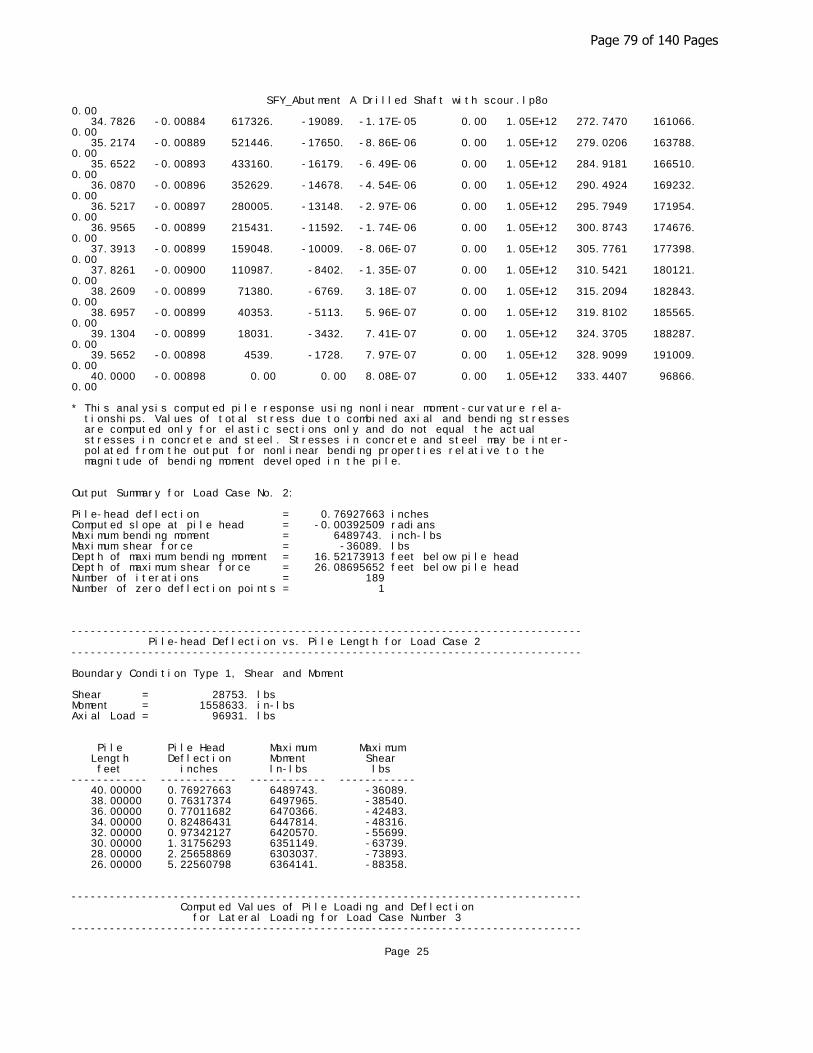
SFY_Abutment A Drilled Shaft with scour.lp8o0.00 34.7826 -0.00884 617326. -19089. -1.17E-05 0.00 1.05E+12 272.7470 161066. 0.00 35.2174 -0.00889 521446. -17650. -8.86E-06 0.00 1.05E+12 279.0206 163788. 0.00 35.6522 -0.00893 433160. -16179. -6.49E-06 0.00 1.05E+12 284.9181 166510. 0.00 36.0870 -0.00896 352629. -14678. -4.54E-06 0.00 1.05E+12 290.4924 169232. 0.00 36.5217 -0.00897 280005. -13148. -2.97E-06 0.00 1.05E+12 295.7949 171954. 0.00 36.9565 -0.00899 215431. -11592. -1.74E-06 0.00 1.05E+12 300.8743 174676. 0.00 37.3913 -0.00899 159048. -10009. -8.06E-07 0.00 1.05E+12 305.7761 177398. 0.00 37.8261 -0.00900 110987. -8402. -1.35E-07 0.00 1.05E+12 310.5421 180121. 0.00 38.2609 -0.00899 71380. -6769. 3.18E-07 0.00 1.05E+12 315.2094 182843. 0.00 38.6957 -0.00899 40353. -5113. 5.96E-07 0.00 1.05E+12 319.8102 185565. 0.00 39.1304 -0.00899 18031. -3432. 7.41E-07 0.00 1.05E+12 324.3705 188287. 0.00 39.5652 -0.00898 4539. -1728. 7.97E-07 0.00 1.05E+12 328.9099 191009. 0.00 40.0000 -0.00898 0.00 0.00 8.08E-07 0.00 1.05E+12 333.4407 96866. 0.00
* This analysis computed pile response using nonlinear moment-curvature rela- tionships. Values of total stress due to combined axial and bending stresses are computed only for elastic sections only and do not equal the actual stresses in concrete and steel. Stresses in concrete and steel may be inter- polated from the output for nonlinear bending properties relative to the magnitude of bending moment developed in the pile.
Output Summary for Load Case No. 2:
Pile-head deflection = 0.76927663 inchesComputed slope at pile head = -0.00392509 radiansMaximum bending moment = 6489743. inch-lbsMaximum shear force = -36089. lbsDepth of maximum bending moment = 16.52173913 feet below pile headDepth of maximum shear force = 26.08695652 feet below pile headNumber of iterations = 189Number of zero deflection points = 1
-------------------------------------------------------------------------------- Pile-head Deflection vs. Pile Length for Load Case 2--------------------------------------------------------------------------------
Boundary Condition Type 1, Shear and Moment
Shear = 28753. lbsMoment = 1558633. in-lbsAxial Load = 96931. lbs
Pile Pile Head Maximum Maximum Length Deflection Moment Shear feet inches ln-lbs lbs ------------ ------------ ------------ ------------ 40.00000 0.76927663 6489743. -36089. 38.00000 0.76317374 6497965. -38540. 36.00000 0.77011682 6470366. -42483. 34.00000 0.82486431 6447814. -48316. 32.00000 0.97342127 6420570. -55699. 30.00000 1.31756293 6351149. -63739. 28.00000 2.25658869 6303037. -73893. 26.00000 5.22560798 6364141. -88358.
-------------------------------------------------------------------------------- Computed Values of Pile Loading and Deflection for Lateral Loading for Load Case Number 3--------------------------------------------------------------------------------
Page 25
Page 79 of 140 Pages

SFY_Abutment A Drilled Shaft with scour.lp8oPile-head conditions are Shear and Moment (Loading Type 1)
Shear force at pile head = 28753.0 lbsApplied moment at pile head = 1543354.0 in-lbsAxial thrust load on pile head = 135553.0 lbs
Depth Deflect. Bending Shear Slope Total Bending Soil Res. Soil Spr. Distrib. X y Moment Force S Stress Stiffness p Es*h Lat. Load feet inches in-lbs lbs radians psi* in-lb^2 lb/inch lb/inch lb/inch ---------- ---------- ---------- ---------- ---------- ---------- ---------- ---------- ---------- ---------- 0.00 0.6316 1543354. 28753. -0.00318 0.00 1.05E+12 0.00 0.00 0.00 0.4348 0.6150 1695614. 28753. -0.00317 0.00 1.05E+12 0.00 0.00 0.00 0.8696 0.5985 1847868. 28753. -0.00316 0.00 1.05E+12 0.00 0.00 0.00 1.3043 0.5820 2000116. 28753. -0.00315 0.00 1.04E+12 0.00 0.00 0.00 1.7391 0.5656 2152356. 28753. -0.00314 0.00 1.04E+12 0.00 0.00 0.00 2.1739 0.5493 2304589. 28753. -0.00313 0.00 1.04E+12 0.00 0.00 0.00 2.6087 0.5330 2456814. 28753. -0.00312 0.00 1.04E+12 0.00 0.00 0.00 3.0435 0.5167 2609030. 28753. -0.00310 0.00 1.04E+12 0.00 0.00 0.00 3.4783 0.5006 2761237. 28753. -0.00309 0.00 1.04E+12 0.00 0.00 0.00 3.9130 0.4845 2913434. 28753. -0.00308 0.00 1.04E+12 0.00 0.00 0.00 4.3478 0.4685 3065621. 28753. -0.00306 0.00 1.04E+12 0.00 0.00 0.00 4.7826 0.4525 3217797. 28753. -0.00305 0.00 1.04E+12 0.00 0.00 0.00 5.2174 0.4367 3369962. 28753. -0.00303 0.00 1.04E+12 0.00 0.00 0.00 5.6522 0.4209 3522114. 28753. -0.00301 0.00 1.04E+12 0.00 0.00 0.00 6.0870 0.4052 3674254. 28753. -0.00299 0.00 1.04E+12 0.00 0.00 0.00 6.5217 0.3897 3826381. 28753. -0.00298 0.00 1.04E+12 0.00 0.00 0.00 6.9565 0.3742 3978495. 28753. -0.00296 0.00 1.04E+12 0.00 0.00 0.00 7.3913 0.3588 4130594. 28753. -0.00294 0.00 1.04E+12 0.00 0.00 0.00 7.8261 0.3436 4282679. 28753. -0.00291 0.00 1.04E+12 0.00 0.00 0.00 8.2609 0.3284 4434748. 28753. -0.00289 0.00 1.04E+12 0.00 0.00 0.00 8.6957 0.3134 4586802. 28753. -0.00287 0.00 1.04E+12 0.00 0.00 0.00 9.1304 0.2985 4738839. 28753. -0.00285 0.00 1.03E+12 0.00 0.00 0.00 9.5652 0.2837 4890859. 28753. -0.00282 0.00 1.03E+12 0.00 0.00 0.00 10.0000 0.2690 5042862. 28661. -0.00280 0.00 1.03E+12 -35.1133 681.0291 0.00 10.4348 0.2545 5193891. 28366. -0.00277 0.00 1.03E+12 -78.0769 1601. 0.00 10.8696 0.2401 5342776. 27844. -0.00274 0.00 1.03E+12 -121.9342 2650. 0.00 11.3043 0.2258 5488323. 27094. -0.00272 0.00 1.03E+12 -165.6982 3828. 0.00 11.7391 0.2117 5629339. 26117. -0.00269 0.00 1.03E+12 -208.8324 5146. 0.00 12.1739 0.1978 5764651. 24915. -0.00266 0.00 1.03E+12 -251.8894 6645. 0.00 12.6087 0.1840 5893086. 23493. -0.00260 0.00 3.19E+11 -293.1105 8312. 0.00 13.0435 0.1707 6013473. 21863. -0.00250 0.00 3.16E+11 -331.9169 10146. 0.00 13.4783 0.1579 6124755. 19681. -0.00240 0.00 3.14E+11 -504.5549 16672. 0.00 13.9130 0.1456 6222231. 17046. -0.00230 0.00 3.13E+11 -505.4681 18108.
Page 26
Page 80 of 140 Pages

SFY_Abutment A Drilled Shaft with scour.lp8o0.00 14.3478 0.1339 6305874. 14408. -0.00219 0.00 3.11E+11 -505.7317 19701. 0.00 14.7826 0.1228 6375675. 11770. -0.00209 0.00 3.10E+11 -505.3472 21476. 0.00 15.2174 0.1122 6431645. 9136. -0.00198 0.00 3.09E+11 -504.3154 23457. 0.00 15.6522 0.1021 6473810. 6510. -0.00187 0.00 3.09E+11 -502.6383 25676. 0.00 16.0870 0.09267 6502214. 3893. -0.00176 0.00 3.08E+11 -500.3202 28167. 0.00 16.5217 0.08379 6516922. 1291. -0.00165 0.00 3.08E+11 -497.3690 30971. 0.00 16.9565 0.07547 6518013. -1295. -0.00154 0.00 3.08E+11 -493.7983 34135. 0.00 17.3913 0.06774 6505584. -3861. -0.00143 0.00 3.08E+11 -489.6287 37713. 0.00 17.8261 0.06058 6479748. -6403. -0.00132 0.00 3.08E+11 -484.8910 41763. 0.00 18.2609 0.05399 6440636. -8919. -0.00121 0.00 3.09E+11 -479.6292 46351. 0.00 18.6957 0.04797 6388391. -11617. -0.00110 0.00 3.10E+11 -554.8076 60347. 0.00 19.1304 0.04251 6320967. -14405. -9.94E-04 0.00 3.11E+11 -513.8220 63070. 0.00 19.5652 0.03760 6239481. -16982. -8.89E-04 0.00 3.12E+11 -474.1139 65792. 0.00 20.0000 0.03323 6145016. -19358. -7.85E-04 0.00 3.14E+11 -436.4239 68514. 0.00 20.4348 0.02940 6038599. -21543. -6.84E-04 0.00 3.16E+11 -401.4518 71236. 0.00 20.8696 0.02609 5921183. -23556. -5.86E-04 0.00 3.18E+11 -369.8549 73958. 0.00 21.3043 0.02329 5793631. -25413. -5.20E-04 0.00 8.49E+11 -342.2456 76680. 0.00 21.7391 0.02067 5656737. -27127. -4.88E-04 0.00 1.03E+12 -314.5367 79402. 0.00 22.1739 0.01820 5511260. -28694. -4.59E-04 0.00 1.03E+12 -286.4469 82124. 0.00 22.6087 0.01587 5357967. -30115. -4.32E-04 0.00 1.03E+12 -258.1462 84846. 0.00 23.0435 0.01369 5197627. -31388. -4.05E-04 0.00 1.03E+12 -229.7930 87569. 0.00 23.4783 0.01165 5031014. -32513. -3.79E-04 0.00 1.03E+12 -201.5335 90291. 0.00 23.9130 0.00973 4858897. -33491. -3.54E-04 0.00 1.03E+12 -173.5023 93013. 0.00 24.3478 0.00795 4682039. -34324. -3.30E-04 0.00 1.03E+12 -145.8220 95735. 0.00 24.7826 0.00628 4501195. -35014. -3.07E-04 0.00 1.04E+12 -118.6034 98457. 0.00 25.2174 0.00474 4317107. -35564. -2.85E-04 0.00 1.04E+12 -91.9450 101179. 0.00 25.6522 0.00331 4130501. -35975. -2.64E-04 0.00 1.04E+12 -65.9341 103901. 0.00 26.0870 0.00199 3942085. -36253. -2.43E-04 0.00 1.04E+12 -40.6466 106623. 0.00 26.5217 7.70E-04 3752548. -36402. -2.24E-04 0.00 1.04E+12 -16.1466 109346. 0.00 26.9565 -3.50E-04 3562559. -36424. -2.06E-04 0.00 1.04E+12 7.5124 112068. 0.00 27.3913 -0.00138 3372761. -36326. -1.88E-04 0.00 1.04E+12 30.2872 114790. 0.00 27.8261 -0.00232 3183776. -36110. -1.72E-04 0.00 1.04E+12 52.1454 117512. 0.00 28.2609 -0.00317 2996199. -35784. -1.56E-04 0.00 1.04E+12 73.0642 120234. 0.00 28.6957 -0.00395 2810601. -35351. -1.42E-04 0.00 1.04E+12 93.0299 122956. 0.00 29.1304 -0.00465 2627525. -34816. -1.28E-04 0.00 1.04E+12 112.0381 125678. 0.00 29.5652 -0.00529 2447489. -34184. -1.16E-04 0.00 1.04E+12 130.0927 128400. 0.00 30.0000 -0.00586 2270986. -33461. -1.04E-04 0.00 1.04E+12 147.2052 131122. 0.00 30.4348 -0.00637 2098482. -32650. -9.29E-05 0.00 1.04E+12 163.3947 133845. 0.00 30.8696 -0.00683 1930419. -31758. -8.28E-05 0.00 1.05E+12 178.6869 136567. 0.00
Page 27
Page 81 of 140 Pages

SFY_Abutment A Drilled Shaft with scour.lp8o 31.3043 -0.00723 1767212. -30788. -7.36E-05 0.00 1.05E+12 193.1139 139289. 0.00 31.7391 -0.00759 1609257. -29745. -6.52E-05 0.00 1.05E+12 206.7131 142011. 0.00 32.1739 -0.00791 1456922. -28633. -5.75E-05 0.00 1.05E+12 219.5269 144733. 0.00 32.6087 -0.00819 1310558. -27456. -5.06E-05 0.00 1.05E+12 231.6020 147455. 0.00 33.0435 -0.00844 1170494. -26218. -4.44E-05 0.00 1.05E+12 242.9893 150177. 0.00 33.4783 -0.00866 1037041. -24922. -3.89E-05 0.00 1.05E+12 253.7421 152899. 0.00 33.9130 -0.00885 910491. -23572. -3.41E-05 0.00 1.05E+12 263.9163 155622. 0.00 34.3478 -0.00901 791121. -22170. -2.98E-05 0.00 1.05E+12 273.5697 158344. 0.00 34.7826 -0.00916 679196. -20718. -2.62E-05 0.00 1.05E+12 282.7611 161066. 0.00 35.2174 -0.00929 574966. -19220. -2.30E-05 0.00 1.05E+12 291.5497 163788. 0.00 35.6522 -0.00940 478670. -17677. -2.04E-05 0.00 1.05E+12 299.9944 166510. 0.00 36.0870 -0.00950 390538. -16091. -1.83E-05 0.00 1.05E+12 308.1529 169232. 0.00 36.5217 -0.00959 310793. -14462. -1.65E-05 0.00 1.05E+12 316.0814 171954. 0.00 36.9565 -0.00967 239652. -12793. -1.51E-05 0.00 1.05E+12 323.8334 174676. 0.00 37.3913 -0.00975 177324. -11083. -1.41E-05 0.00 1.05E+12 331.4591 177398. 0.00 37.8261 -0.00982 124019. -9334. -1.33E-05 0.00 1.05E+12 339.0048 180121. 0.00 38.2609 -0.00989 79941. -7546. -1.28E-05 0.00 1.05E+12 346.5118 182843. 0.00 38.6957 -0.00995 45296. -5719. -1.25E-05 0.00 1.05E+12 354.0158 185565. 0.00 39.1304 -0.01002 20287. -3852. -1.24E-05 0.00 1.05E+12 361.5461 188287. 0.00 39.5652 -0.01008 5119. -1946. -1.23E-05 0.00 1.05E+12 369.1247 191009. 0.00 40.0000 -0.01015 0.00 0.00 -1.23E-05 0.00 1.05E+12 376.7654 96866. 0.00
* This analysis computed pile response using nonlinear moment-curvature rela- tionships. Values of total stress due to combined axial and bending stresses are computed only for elastic sections only and do not equal the actual stresses in concrete and steel. Stresses in concrete and steel may be inter- polated from the output for nonlinear bending properties relative to the magnitude of bending moment developed in the pile.
Output Summary for Load Case No. 3:
Pile-head deflection = 0.63157720 inchesComputed slope at pile head = -0.00317746 radiansMaximum bending moment = 6518013. inch-lbsMaximum shear force = -36424. lbsDepth of maximum bending moment = 16.95652174 feet below pile headDepth of maximum shear force = 26.95652174 feet below pile headNumber of iterations = 77Number of zero deflection points = 1
-------------------------------------------------------------------------------- Pile-head Deflection vs. Pile Length for Load Case 3--------------------------------------------------------------------------------
Boundary Condition Type 1, Shear and Moment
Shear = 28753. lbsMoment = 1543354. in-lbsAxial Load = 135553. lbs
Pile Pile Head Maximum Maximum Length Deflection Moment Shear feet inches ln-lbs lbs ------------ ------------ ------------ ------------
Page 28
Page 82 of 140 Pages
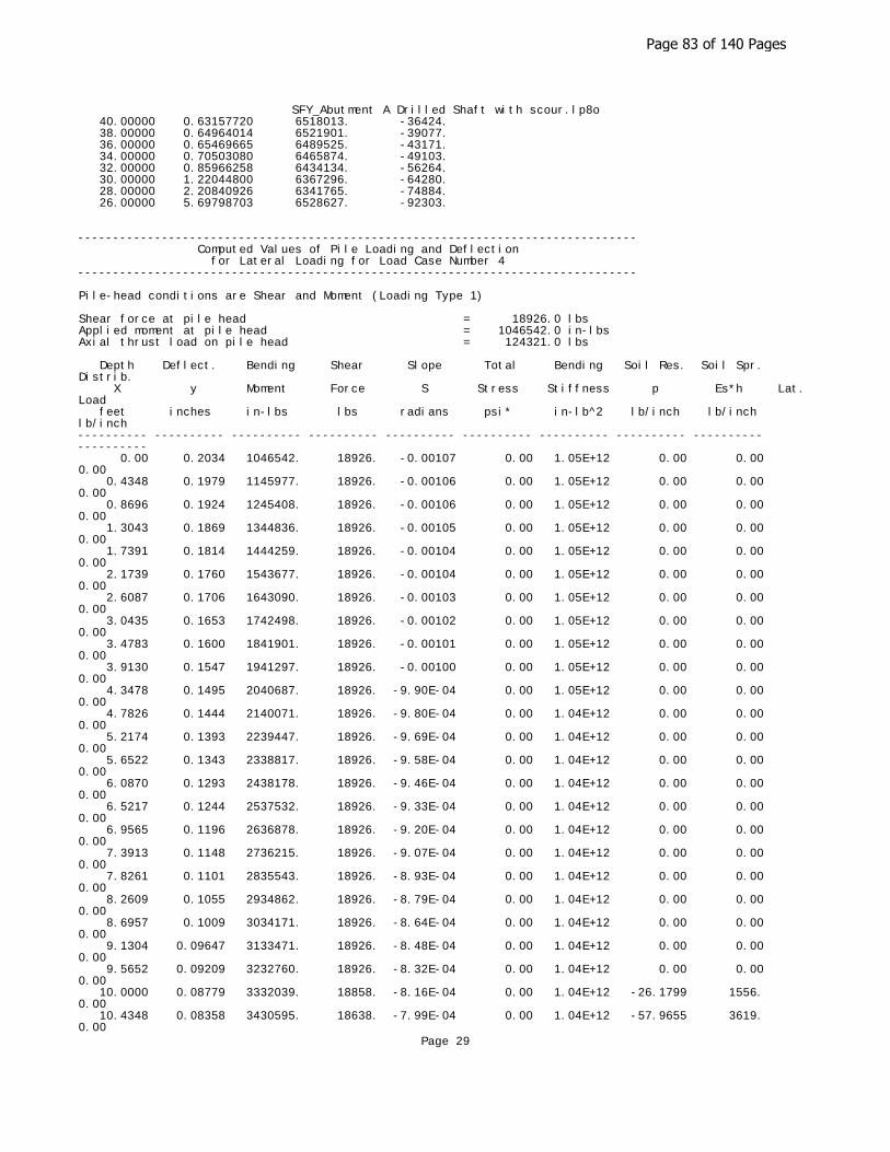
SFY_Abutment A Drilled Shaft with scour.lp8o 40.00000 0.63157720 6518013. -36424. 38.00000 0.64964014 6521901. -39077. 36.00000 0.65469665 6489525. -43171. 34.00000 0.70503080 6465874. -49103. 32.00000 0.85966258 6434134. -56264. 30.00000 1.22044800 6367296. -64280. 28.00000 2.20840926 6341765. -74884. 26.00000 5.69798703 6528627. -92303.
-------------------------------------------------------------------------------- Computed Values of Pile Loading and Deflection for Lateral Loading for Load Case Number 4--------------------------------------------------------------------------------
Pile-head conditions are Shear and Moment (Loading Type 1)
Shear force at pile head = 18926.0 lbsApplied moment at pile head = 1046542.0 in-lbsAxial thrust load on pile head = 124321.0 lbs
Depth Deflect. Bending Shear Slope Total Bending Soil Res. Soil Spr. Distrib. X y Moment Force S Stress Stiffness p Es*h Lat. Load feet inches in-lbs lbs radians psi* in-lb^2 lb/inch lb/inch lb/inch ---------- ---------- ---------- ---------- ---------- ---------- ---------- ---------- ---------- ---------- 0.00 0.2034 1046542. 18926. -0.00107 0.00 1.05E+12 0.00 0.00 0.00 0.4348 0.1979 1145977. 18926. -0.00106 0.00 1.05E+12 0.00 0.00 0.00 0.8696 0.1924 1245408. 18926. -0.00106 0.00 1.05E+12 0.00 0.00 0.00 1.3043 0.1869 1344836. 18926. -0.00105 0.00 1.05E+12 0.00 0.00 0.00 1.7391 0.1814 1444259. 18926. -0.00104 0.00 1.05E+12 0.00 0.00 0.00 2.1739 0.1760 1543677. 18926. -0.00104 0.00 1.05E+12 0.00 0.00 0.00 2.6087 0.1706 1643090. 18926. -0.00103 0.00 1.05E+12 0.00 0.00 0.00 3.0435 0.1653 1742498. 18926. -0.00102 0.00 1.05E+12 0.00 0.00 0.00 3.4783 0.1600 1841901. 18926. -0.00101 0.00 1.05E+12 0.00 0.00 0.00 3.9130 0.1547 1941297. 18926. -0.00100 0.00 1.05E+12 0.00 0.00 0.00 4.3478 0.1495 2040687. 18926. -9.90E-04 0.00 1.05E+12 0.00 0.00 0.00 4.7826 0.1444 2140071. 18926. -9.80E-04 0.00 1.04E+12 0.00 0.00 0.00 5.2174 0.1393 2239447. 18926. -9.69E-04 0.00 1.04E+12 0.00 0.00 0.00 5.6522 0.1343 2338817. 18926. -9.58E-04 0.00 1.04E+12 0.00 0.00 0.00 6.0870 0.1293 2438178. 18926. -9.46E-04 0.00 1.04E+12 0.00 0.00 0.00 6.5217 0.1244 2537532. 18926. -9.33E-04 0.00 1.04E+12 0.00 0.00 0.00 6.9565 0.1196 2636878. 18926. -9.20E-04 0.00 1.04E+12 0.00 0.00 0.00 7.3913 0.1148 2736215. 18926. -9.07E-04 0.00 1.04E+12 0.00 0.00 0.00 7.8261 0.1101 2835543. 18926. -8.93E-04 0.00 1.04E+12 0.00 0.00 0.00 8.2609 0.1055 2934862. 18926. -8.79E-04 0.00 1.04E+12 0.00 0.00 0.00 8.6957 0.1009 3034171. 18926. -8.64E-04 0.00 1.04E+12 0.00 0.00 0.00 9.1304 0.09647 3133471. 18926. -8.48E-04 0.00 1.04E+12 0.00 0.00 0.00 9.5652 0.09209 3232760. 18926. -8.32E-04 0.00 1.04E+12 0.00 0.00 0.00 10.0000 0.08779 3332039. 18858. -8.16E-04 0.00 1.04E+12 -26.1799 1556. 0.00 10.4348 0.08358 3430595. 18638. -7.99E-04 0.00 1.04E+12 -57.9655 3619. 0.00
Page 29
Page 83 of 140 Pages

SFY_Abutment A Drilled Shaft with scour.lp8o 10.8696 0.07945 3527561. 18256. -7.81E-04 0.00 1.04E+12 -88.6398 5821. 0.00 11.3043 0.07542 3622103. 17728. -7.63E-04 0.00 1.04E+12 -113.6571 7862. 0.00 11.7391 0.07149 3713539. 17078. -7.45E-04 0.00 1.04E+12 -135.7000 9904. 0.00 12.1739 0.06765 3801270. 16319. -7.26E-04 0.00 1.04E+12 -154.8857 11945. 0.00 12.6087 0.06391 3884772. 15468. -7.07E-04 0.00 1.04E+12 -171.3346 13987. 0.00 13.0435 0.06027 3963597. 14538. -6.87E-04 0.00 1.04E+12 -185.1703 16029. 0.00 13.4783 0.05674 4037368. 13036. -6.67E-04 0.00 1.04E+12 -390.6662 35922. 0.00 13.9130 0.05331 4100493. 10991. -6.47E-04 0.00 1.04E+12 -393.1857 38478. 0.00 14.3478 0.04999 4152900. 8934. -6.26E-04 0.00 1.04E+12 -395.3178 41255. 0.00 14.7826 0.04678 4194534. 6867. -6.05E-04 0.00 1.04E+12 -397.0603 44280. 0.00 15.2174 0.04368 4225345. 4792. -5.84E-04 0.00 1.04E+12 -398.4085 47584. 0.00 15.6522 0.04069 4245297. 2711. -5.62E-04 0.00 1.04E+12 -399.3561 51201. 0.00 16.0870 0.03782 4254364. 626.1306 -5.41E-04 0.00 1.04E+12 -399.8948 55172. 0.00 16.5217 0.03505 4252532. -1461. -5.20E-04 0.00 1.04E+12 -400.0151 59544. 0.00 16.9565 0.03240 4239797. -3547. -4.98E-04 0.00 1.04E+12 -399.7057 64373. 0.00 17.3913 0.02985 4216168. -5630. -4.77E-04 0.00 1.04E+12 -398.9534 69726. 0.00 17.8261 0.02742 4181665. -7709. -4.56E-04 0.00 1.04E+12 -397.7429 75682. 0.00 18.2609 0.02510 4136321. -9779. -4.35E-04 0.00 1.04E+12 -396.0559 82336. 0.00 18.6957 0.02288 4080183. -11503. -4.14E-04 0.00 1.04E+12 -264.6739 60347. 0.00 19.1304 0.02078 4016827. -12849. -3.94E-04 0.00 1.04E+12 -251.1394 63070. 0.00 19.5652 0.01877 3946621. -14121. -3.74E-04 0.00 1.04E+12 -236.7345 65792. 0.00 20.0000 0.01688 3869959. -15317. -3.54E-04 0.00 1.04E+12 -221.5996 68514. 0.00 20.4348 0.01508 3787251. -16432. -3.35E-04 0.00 1.04E+12 -205.8687 71236. 0.00 20.8696 0.01338 3698927. -17464. -3.16E-04 0.00 1.04E+12 -189.6695 73958. 0.00 21.3043 0.01178 3605428. -18410. -2.98E-04 0.00 1.04E+12 -173.1229 76680. 0.00 21.7391 0.01027 3507205. -19270. -2.80E-04 0.00 1.04E+12 -156.3428 79402. 0.00 22.1739 0.00886 3404715. -20041. -2.63E-04 0.00 1.04E+12 -139.4359 82124. 0.00 22.6087 0.00753 3298417. -20725. -2.46E-04 0.00 1.04E+12 -122.5016 84846. 0.00 23.0435 0.00629 3188775. -21320. -2.30E-04 0.00 1.04E+12 -105.6320 87569. 0.00 23.4783 0.00514 3076247. -21827. -2.14E-04 0.00 1.04E+12 -88.9120 90291. 0.00 23.9130 0.00406 2961288. -22248. -1.99E-04 0.00 1.04E+12 -72.4191 93013. 0.00 24.3478 0.00306 2844348. -22584. -1.84E-04 0.00 1.04E+12 -56.2234 95735. 0.00 24.7826 0.00214 2725869. -22836. -1.70E-04 0.00 1.04E+12 -40.3878 98457. 0.00 25.2174 0.00129 2606281. -23006. -1.57E-04 0.00 1.04E+12 -24.9678 101179. 0.00 25.6522 5.03E-04 2486006. -23098. -1.44E-04 0.00 1.04E+12 -10.0119 103901. 0.00 26.0870 -2.17E-04 2365450. -23112. -1.32E-04 0.00 1.04E+12 4.4379 106623. 0.00 26.5217 -8.75E-04 2245007. -23053. -1.21E-04 0.00 1.04E+12 18.3465 109346. 0.00 26.9565 -0.00148 2125056. -22922. -1.10E-04 0.00 1.04E+12 31.6853 112068. 0.00 27.3913 -0.00202 2005960. -22724. -9.93E-05 0.00 1.05E+12 44.4320 114790. 0.00 27.8261 -0.00251 1888068. -22460. -8.96E-05 0.00 1.05E+12 56.5703 117512.
Page 30
Page 84 of 140 Pages
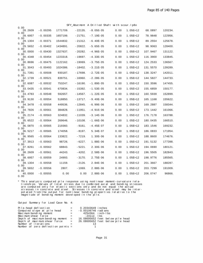
SFY_Abutment A Drilled Shaft with scour.lp8o0.00 28.2609 -0.00295 1771709. -22135. -8.05E-05 0.00 1.05E+12 68.0897 120234. 0.00 28.6957 -0.00335 1657199. -21751. -7.19E-05 0.00 1.05E+12 78.9848 122956. 0.00 29.1304 -0.00371 1544832. -21312. -6.40E-05 0.00 1.05E+12 89.2554 125678. 0.00 29.5652 -0.00402 1434891. -20822. -5.65E-05 0.00 1.05E+12 98.9063 128400. 0.00 30.0000 -0.00430 1327637. -20282. -4.96E-05 0.00 1.05E+12 107.9467 131122. 0.00 30.4348 -0.00454 1223318. -19697. -4.33E-05 0.00 1.05E+12 116.3900 133845. 0.00 30.8696 -0.00475 1122162. -19069. -3.75E-05 0.00 1.05E+12 124.2533 136567. 0.00 31.3043 -0.00493 1024386. -18402. -3.21E-05 0.00 1.05E+12 131.5570 139289. 0.00 31.7391 -0.00508 930187. -17698. -2.72E-05 0.00 1.05E+12 138.3247 142011. 0.00 32.1739 -0.00521 839751. -16960. -2.28E-05 0.00 1.05E+12 144.5827 144733. 0.00 32.6087 -0.00532 753247. -16190. -1.89E-05 0.00 1.05E+12 150.3596 147455. 0.00 33.0435 -0.00541 670834. -15392. -1.53E-05 0.00 1.05E+12 155.6859 150177. 0.00 33.4783 -0.00548 592657. -14567. -1.22E-05 0.00 1.05E+12 160.5939 152899. 0.00 33.9130 -0.00554 518850. -13717. -9.40E-06 0.00 1.05E+12 165.1168 155622. 0.00 34.3478 -0.00558 449536. -12845. -6.99E-06 0.00 1.05E+12 169.2887 158344. 0.00 34.7826 -0.00561 384828. -11951. -4.91E-06 0.00 1.05E+12 173.1442 161066. 0.00 35.2174 -0.00563 324832. -11039. -3.14E-06 0.00 1.05E+12 176.7178 163788. 0.00 35.6522 -0.00564 269646. -10108. -1.66E-06 0.00 1.05E+12 180.0435 166510. 0.00 36.0870 -0.00565 219360. -9161. -4.45E-07 0.00 1.05E+12 183.1546 169232. 0.00 36.5217 -0.00565 174058. -8197. 5.34E-07 0.00 1.05E+12 186.0833 171954. 0.00 36.9565 -0.00564 133822. -7219. 1.30E-06 0.00 1.05E+12 188.8600 174676. 0.00 37.3913 -0.00563 98726. -6227. 1.88E-06 0.00 1.05E+12 191.5132 177398. 0.00 37.8261 -0.00562 68843. -5221. 2.30E-06 0.00 1.05E+12 194.0690 180121. 0.00 38.2609 -0.00561 44243. -4202. 2.58E-06 0.00 1.05E+12 196.5505 182843. 0.00 38.6957 -0.00559 24993. -3170. 2.75E-06 0.00 1.05E+12 198.9776 185565. 0.00 39.1304 -0.00558 11159. -2126. 2.84E-06 0.00 1.05E+12 201.3667 188287. 0.00 39.5652 -0.00556 2807. -1069. 2.88E-06 0.00 1.05E+12 203.7299 191009. 0.00 40.0000 -0.00555 0.00 0.00 2.88E-06 0.00 1.05E+12 206.0747 96866. 0.00
* This analysis computed pile response using nonlinear moment-curvature rela- tionships. Values of total stress due to combined axial and bending stresses are computed only for elastic sections only and do not equal the actual stresses in concrete and steel. Stresses in concrete and steel may be inter- polated from the output for nonlinear bending properties relative to the magnitude of bending moment developed in the pile.
Output Summary for Load Case No. 4:
Pile-head deflection = 0.20343649 inchesComputed slope at pile head = -0.00106746 radiansMaximum bending moment = 4254364. inch-lbsMaximum shear force = -23112. lbsDepth of maximum bending moment = 16.08695652 feet below pile headDepth of maximum shear force = 26.08695652 feet below pile headNumber of iterations = 13Number of zero deflection points = 1
Page 31
Page 85 of 140 Pages

SFY_Abutment A Drilled Shaft with scour.lp8o-------------------------------------------------------------------------------- Pile-head Deflection vs. Pile Length for Load Case 4--------------------------------------------------------------------------------
Boundary Condition Type 1, Shear and Moment
Shear = 18926. lbsMoment = 1046542. in-lbsAxial Load = 124321. lbs
Pile Pile Head Maximum Maximum Length Deflection Moment Shear feet inches ln-lbs lbs ------------ ------------ ------------ ------------ 40.00000 0.20343649 4254364. -23112. 38.00000 0.20859267 4254909. -24559. 36.00000 0.21335876 4220401. -26346. 34.00000 0.23353152 4193582. -29409. 32.00000 0.28508537 4170346. -33572. 30.00000 0.39148715 4128918. -38486. 28.00000 0.65908460 4093567. -45170. 26.00000 1.43330134 4088984. -53895. 24.00000 4.26149056 4217425. -66033.
-------------------------------------------------------------------------------- Summary of Pile-head Responses for Conventional Analyses--------------------------------------------------------------------------------
Definitions of Pile-head Loading Conditions:
Load Type 1: Load 1 = Shear, V, lbs, and Load 2 = Moment, M, in-lbsLoad Type 2: Load 1 = Shear, V, lbs, and Load 2 = Slope, S, radiansLoad Type 3: Load 1 = Shear, V, lbs, and Load 2 = Rot. Stiffness, R, in-lbs/rad.Load Type 4: Load 1 = Top Deflection, y, inches, and Load 2 = Moment, M, in-lbsLoad Type 5: Load 1 = Top Deflection, y, inches, and Load 2 = Slope, S, radians
Load Load Load Axial Pile-head Pile-head Max Shear Max MomentCase Type Pile-head Type Pile-head Loading Deflection Rotation in Pile in Pile No. 1 Load 1 2 Load 2 lbs inches radians lbs in-lbs ---- ----- ---------- ---------- ---------- ---------- ---------- ---------- ---------- ---------- 1 V, lb 23269. M, in-lb 1112698. 167644. 0.2574 -0.00131 -28331. 5112676. 2 V, lb 28753. M, in-lb 1558633. 96931. 0.7693 -0.00393 -36089. 6489743. 3 V, lb 28753. M, in-lb 1543354. 135553. 0.6316 -0.00318 -36424. 6518013. 4 V, lb 18926. M, in-lb 1046542. 124321. 0.2034 -0.00107 -23112. 4254364.
Maximum pile-head deflection = 0.769276626 inchesMaximum pile-head rotation = -0.003925093 radians
The analysis ended normally.
Page 32
Page 86 of 140 Pages
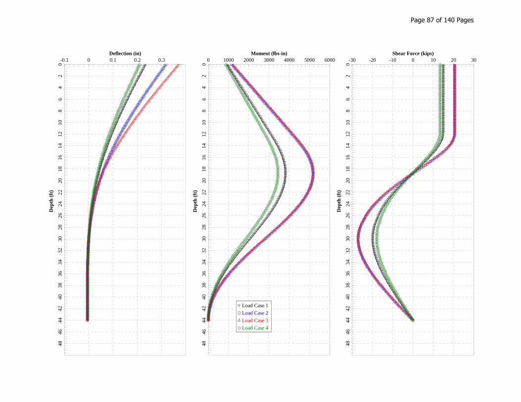
Deflection (in) Moment (lbs-in) Shear Force (kips)D
epth
(ft
)
Dep
th (
ft)
Dep
th (
ft)
-0.1 0 0.1 0.2 0.30
24
68
1012
1416
1820
2224
2628
3032
3436
3840
4244
4648
0 1000 2000 3000 4000 5000 6000
02
46
810
1214
1618
2022
2426
2830
3234
3638
4042
4446
48
-30 -20 -10 0 10 20 30
02
46
810
1214
1618
2022
2426
2830
3234
3638
4042
4446
48
Load Case 1
Load Case 2
Load Case 3
Load Case 4
Page 87 of 140 Pages

SFY_Abutment B Drilled Shaft with scour.lp8o================================================================================
LPile for Windows, Version 2015-08.002
Analysis of Individual Piles and Drilled Shafts Subjected to Lateral Loading Using the p-y Method © 1985-2015 by Ensoft, Inc. All Rights Reserved
================================================================================
This copy of LPile is being used by:
DKGeoconcepts Engineering, Inc.
Serial Number of Security Device: 151268435
This copy of LPile is licensed for exclusive use by:
GeoConcepts Engineering, Inc., A
Use of this program by any entity other than GeoConcepts Engineering, Inc., Ais a violation of the software license agreement.
-------------------------------------------------------------------------------- Files Used for Analysis--------------------------------------------------------------------------------
Path to file locations:\\GEODATA\GeoConcepts\PROJECTS\Active 14 Projects\14156, Dewberry IDIQ\Calcs and Excel\LPILE\
Name of input data file: SFY_Abutment B Drilled Shaft with scour.lp8d
Name of output report file: SFY_Abutment B Drilled Shaft with scour.lp8o
Name of plot output file: SFY_Abutment B Drilled Shaft with scour.lp8p
Name of runtime message file: SFY_Abutment B Drilled Shaft with scour.lp8r
-------------------------------------------------------------------------------- Date and Time of Analysis--------------------------------------------------------------------------------
Date: December 4, 2015 Time: 12:10:18
-------------------------------------------------------------------------------- Problem Title--------------------------------------------------------------------------------
Project Name: Powell's Creek Job Number: 50054145 Engineer: SFY Checker: EJA Description: Abutment B Drilled Shaft with Scour
-------------------------------------------------------------------------------- Program Options and Settings
Page 1
Page 88 of 140 Pages

SFY_Abutment B Drilled Shaft with scour.lp8o--------------------------------------------------------------------------------
Computational Options: - Use unfactored loads in computations (conventional analysis)Engineering Units Used for Data Input and Computations: - US Customary System Units (pounds, feet, inches)
Analysis Control Options: - Maximum number of iterations allowed = 500 - Deflection tolerance for convergence = 1.0000E-05 in - Maximum allowable deflection = 100.0000 in - Number of pile increments = 200
Loading Type and Number of Cycles of Loading: - Static loading specified
- Analysis uses p-y modification factors for p-y curves - No distributed lateral loads are entered - Loading by lateral soil movements acting on pile not selected - Input of shear resistance at the pile tip not selected - Computation of pile-head foundation stiffness matrix not selected - Push-over analysis of pile not selected - Buckling analysis of pile not selected
Output Options: - Output files use decimal points to denote decimal symbols. - Values of pile-head deflection, bending moment, shear force, and soil reaction are printed for full length of pile. - Printing Increment (nodal spacing of output points) = 1 - No p-y curves to be computed and reported for user-specified depths - Print using wide report formats
-------------------------------------------------------------------------------- Pile Structural Properties and Geometry--------------------------------------------------------------------------------
Total number of pile sections = 1
Total length of pile = 44.00 ft
Depth of ground surface below top of pile = 11.74 ft
Pile diameters used for p-y curve computations are defined using 2 points.
p-y curves are computed using pile diameter values interpolated with depth over the length of the pile.
Point Depth Pile X Diameter ft in----- --------- ----------- 1 0.00000 48.00000000 2 44.0000000 48.00000000
Input Structural Properties:----------------------------
Pile Section No. 1:
Section Type = Drilled Shaft (Bored Pile) Section Length = 44.000000 ft Section Diameter = 48.000000 in Shear Capacity of Section = 0.0000 lbs
-------------------------------------------------------------------------------- Ground Slope and Pile Batter Angles--------------------------------------------------------------------------------
Ground Slope Angle = 0.000 degrees = 0.000 radians
Pile Batter Angle = 0.000 degreesPage 2
Page 89 of 140 Pages
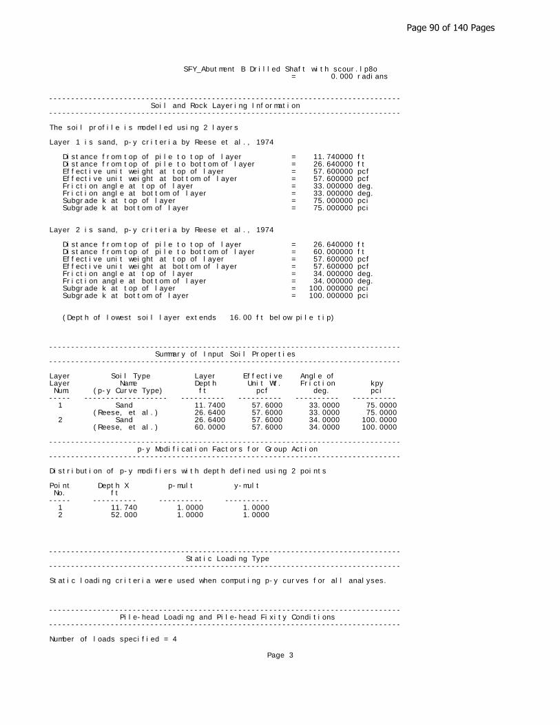
SFY_Abutment B Drilled Shaft with scour.lp8o = 0.000 radians
-------------------------------------------------------------------------------- Soil and Rock Layering Information--------------------------------------------------------------------------------
The soil profile is modelled using 2 layers
Layer 1 is sand, p-y criteria by Reese et al., 1974
Distance from top of pile to top of layer = 11.740000 ft Distance from top of pile to bottom of layer = 26.640000 ft Effective unit weight at top of layer = 57.600000 pcf Effective unit weight at bottom of layer = 57.600000 pcf Friction angle at top of layer = 33.000000 deg. Friction angle at bottom of layer = 33.000000 deg. Subgrade k at top of layer = 75.000000 pci Subgrade k at bottom of layer = 75.000000 pci
Layer 2 is sand, p-y criteria by Reese et al., 1974
Distance from top of pile to top of layer = 26.640000 ft Distance from top of pile to bottom of layer = 60.000000 ft Effective unit weight at top of layer = 57.600000 pcf Effective unit weight at bottom of layer = 57.600000 pcf Friction angle at top of layer = 34.000000 deg. Friction angle at bottom of layer = 34.000000 deg. Subgrade k at top of layer = 100.000000 pci Subgrade k at bottom of layer = 100.000000 pci
(Depth of lowest soil layer extends 16.00 ft below pile tip)
-------------------------------------------------------------------------------- Summary of Input Soil Properties--------------------------------------------------------------------------------
Layer Soil Type Layer Effective Angle of Layer Name Depth Unit Wt. Friction kpy Num. (p-y Curve Type) ft pcf deg. pci ----- ------------------- ---------- ---------- ---------- ---------- 1 Sand 11.7400 57.6000 33.0000 75.0000 (Reese, et al.) 26.6400 57.6000 33.0000 75.0000 2 Sand 26.6400 57.6000 34.0000 100.0000 (Reese, et al.) 60.0000 57.6000 34.0000 100.0000
-------------------------------------------------------------------------------- p-y Modification Factors for Group Action--------------------------------------------------------------------------------
Distribution of p-y modifiers with depth defined using 2 points
Point Depth X p-mult y-mult No. ft----- ---------- ---------- ---------- 1 11.740 1.0000 1.0000 2 52.000 1.0000 1.0000
-------------------------------------------------------------------------------- Static Loading Type--------------------------------------------------------------------------------
Static loading criteria were used when computing p-y curves for all analyses.
-------------------------------------------------------------------------------- Pile-head Loading and Pile-head Fixity Conditions--------------------------------------------------------------------------------
Number of loads specified = 4
Page 3
Page 90 of 140 Pages
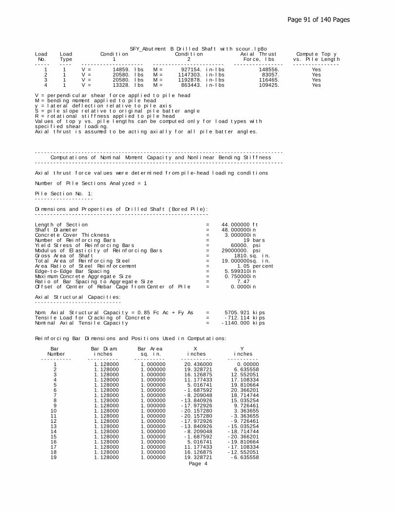
SFY_Abutment B Drilled Shaft with scour.lp8oLoad Load Condition Condition Axial Thrust Compute Top y No. Type 1 2 Force, lbs vs. Pile Length----- ---- -------------------- ----------------------- ---------------- --------------- 1 1 V = 14859. lbs M = 927154. in-lbs 148556. Yes 2 1 V = 20580. lbs M = 1147303. in-lbs 83057. Yes 3 1 V = 20580. lbs M = 1192878. in-lbs 116465. Yes 4 1 V = 13328. lbs M = 863443. in-lbs 109425. Yes
V = perpendicular shear force applied to pile headM = bending moment applied to pile heady = lateral deflection relative to pile axisS = pile slope relative to original pile batter angleR = rotational stiffness applied to pile headValues of top y vs. pile lengths can be computed only for load types withspecified shear loading.Axial thrust is assumed to be acting axially for all pile batter angles.
-------------------------------------------------------------------------------- Computations of Nominal Moment Capacity and Nonlinear Bending Stiffness--------------------------------------------------------------------------------
Axial thrust force values were determined from pile-head loading conditions
Number of Pile Sections Analyzed = 1
Pile Section No. 1:-------------------
Dimensions and Properties of Drilled Shaft (Bored Pile):--------------------------------------------------------
Length of Section = 44.000000 ftShaft Diameter = 48.000000in Concrete Cover Thickness = 3.000000in Number of Reinforcing Bars = 19 bars Yield Stress of Reinforcing Bars = 60000. psiModulus of Elasticity of Reinforcing Bars = 29000000. psiGross Area of Shaft = 1810.sq. in. Total Area of Reinforcing Steel = 19.000000sq. in. Area Ratio of Steel Reinforcement = 1.05 percentEdge-to-Edge Bar Spacing = 5.599310in Maximum Concrete Aggregate Size = 0.750000in Ratio of Bar Spacing to Aggregate Size = 7.47Offset of Center of Rebar Cage from Center of Pile = 0.0000in
Axial Structural Capacities:----------------------------
Nom. Axial Structural Capacity = 0.85 Fc Ac + Fy As = 5705.921 kips Tensile Load for Cracking of Concrete = -712.114 kips Nominal Axial Tensile Capacity = -1140.000 kips
Reinforcing Bar Dimensions and Positions Used in Computations:
Bar Bar Diam. Bar Area X Y Number inches sq. in. inches inches ---------- ---------- ---------- ---------- ---------- 1 1.128000 1.000000 20.436000 0.00000 2 1.128000 1.000000 19.328721 6.635558 3 1.128000 1.000000 16.126875 12.552051 4 1.128000 1.000000 11.177433 17.108334 5 1.128000 1.000000 5.016741 19.810664 6 1.128000 1.000000 -1.687592 20.366201 7 1.128000 1.000000 -8.209048 18.714744 8 1.128000 1.000000 -13.840926 15.035254 9 1.128000 1.000000 -17.972926 9.726461 10 1.128000 1.000000 -20.157280 3.363655 11 1.128000 1.000000 -20.157280 -3.363655 12 1.128000 1.000000 -17.972926 -9.726461 13 1.128000 1.000000 -13.840926 -15.035254 14 1.128000 1.000000 -8.209048 -18.714744 15 1.128000 1.000000 -1.687592 -20.366201 16 1.128000 1.000000 5.016741 -19.810664 17 1.128000 1.000000 11.177433 -17.108334 18 1.128000 1.000000 16.126875 -12.552051 19 1.128000 1.000000 19.328721 -6.635558
Page 4
Page 91 of 140 Pages
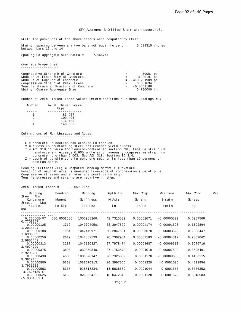
SFY_Abutment B Drilled Shaft with scour.lp8o
NOTE: The positions of the above rebars were computed by LPile
Minimum spacing between any two bars not equal to zero = 5.599310 inchesbetween bars 13 and 14
Spacing to aggregate size ratio = 7.465747
Concrete Properties:--------------------
Compressive Strength of Concrete = 3000. psiModulus of Elasticity of Concrete = 3122019. psiModulus of Rupture of Concrete = -410.791909 psiCompression Strain at Peak Stress = 0.001634Tensile Strain at Fracture of Concrete = -0.0001160Maximum Coarse Aggregate Size = 0.750000 in
Number of Axial Thrust Force Values Determined from Pile-head Loadings = 4
Number Axial Thrust Force kips ------ ------------------ 1 83.057 2 109.425 3 116.465 4 148.556
Definitions of Run Messages and Notes:--------------------------------------
C = concrete in section has cracked in tension. Y = stress in reinforcing steel has reached yield stress. T = ACI 318 criteria for tension-controlled section met, tensile strain in reinforcement exceeds 0.005 while simultaneously compressive strain in concrete more than 0.003. See ACI 318, Section 10.3.4. Z = depth of tensile zone in concrete section is less than 10 percent of section depth.
Bending Stiffness (EI) = Computed Bending Moment / Curvature.Position of neutral axis is measured from edge of compression side of pile.Compressive stresses and strains are positive in sign.Tensile stresses and strains are negative in sign.
Axial Thrust Force = 83.057 kips
Bending Bending Bending Depth to Max Comp Max Tens Max Conc Max Steel Run Curvature Moment Stiffness N Axis Strain Strain Stress Stress Msg rad/in. in-kip kip-in2 in in/in in/in ksi ksi ------------- ------------- ------------- ------------- ------------- ------------- ------------- ------------- --- 6.25000E-07 656.8551660 1050968266. 42.7315682 0.00002671 -0.00000329 0.0967508 0.7701597 0.00000125 1312. 1049704050. 33.3947699 0.00004174 -0.00001826 0.1502894 1.2018604 0.00000188 1964. 1047449971. 30.2847604 0.00005678 -0.00003322 0.2033447 1.6336839 0.00000250 2612. 1044869599. 28.7302934 0.00007183 -0.00004817 0.2559062 2.0655463 0.00000313 3257. 1042150327. 27.7978474 0.00008687 -0.00006313 0.3079716 2.4974299 0.00000375 3898. 1039359840. 27.1763570 0.0001019 -0.00007809 0.3595401 2.9293288 0.00000438 4535. 1036528147. 26.7325359 0.0001170 -0.00009305 0.4106115 3.3612405 0.00000500 5168. 1033670513. 26.3997500 0.0001320 -0.0001080 0.4611854 3.7931638 0.00000563 5168. 918818234. 18.5638689 0.0001044 -0.0001656 0.3666353 -4.7626189 C 0.00000625 5168. 826936411. 18.0472545 0.0001128 -0.0001872 0.3948583 -5.3854351 C
Page 5
Page 92 of 140 Pages

SFY_Abutment B Drilled Shaft with scour.lp8o 0.00000688 5168. 751760373. 17.6119822 0.0001211 -0.0002089 0.4226347 -6.0107611 C 0.00000750 5168. 689113675. 17.2405665 0.0001293 -0.0002307 0.4500415 -6.6379768 C 0.00000813 5168. 636104931. 16.9210030 0.0001375 -0.0002525 0.4771572 -7.2664386 C 0.00000875 5168. 590668865. 16.6423470 0.0001456 -0.0002744 0.5039887 -7.8961044 C 0.00000938 5168. 551290940. 16.3962325 0.0001537 -0.0002963 0.5305328 -8.5270243 C 0.00001000 5168. 516835257. 16.1790830 0.0001618 -0.0003182 0.5568753 -9.1584659 C 0.00001063 5168. 486433183. 15.9849015 0.0001698 -0.0003402 0.5829862 -9.7907022 C 0.00001125 5168. 459409117. 15.8098231 0.0001779 -0.0003621 0.6088656 -10.4237452 C 0.00001188 5168. 435229690. 15.6536581 0.0001859 -0.0003841 0.6346245 -11.0566215 C 0.00001250 5168. 413468205. 15.5105506 0.0001939 -0.0004061 0.6601401 -11.6904254 C 0.00001313 5168. 393779243. 15.3798196 0.0002019 -0.0004281 0.6854643 -12.3247061 C 0.00001375 5168. 375880187. 15.2613956 0.0002098 -0.0004502 0.7106693 -12.9588185 C 0.00001438 5168. 359537570. 15.1536746 0.0002178 -0.0004722 0.7357549 -13.5927618 C 0.00001500 5168. 344556838. 15.0529871 0.0002258 -0.0004942 0.7606099 -14.2275506 C 0.00001563 5168. 330774564. 14.9596168 0.0002337 -0.0005163 0.7852913 -14.8626736 C 0.00001625 5168. 318052466. 14.8737936 0.0002417 -0.0005383 0.8098545 -15.4976247 C 0.00001688 5168. 306272745. 14.7946801 0.0002497 -0.0005603 0.8342993 -16.1324034 C 0.00001750 5168. 295334432. 14.7215587 0.0002576 -0.0005824 0.8586255 -16.7670089 C 0.00001813 5225. 288281823. 14.6538108 0.0002656 -0.0006044 0.8828327 -17.4014406 C 0.00001875 5370. 286426477. 14.5890979 0.0002735 -0.0006265 0.9068171 -18.0366780 C 0.00001938 5516. 284683295. 14.5284022 0.0002815 -0.0006485 0.9306556 -18.6720039 C 0.00002000 5661. 283043608. 14.4718070 0.0002894 -0.0006706 0.9543761 -19.3071519 C 0.00002063 5806. 281497989. 14.4189407 0.0002974 -0.0006926 0.9779785 -19.9421211 C 0.00002125 5951. 280038120. 14.3694753 0.0003054 -0.0007146 1.0014625 -20.5769108 C 0.00002188 6096. 278656634. 14.3231204 0.0003133 -0.0007367 1.0248279 -21.2115204 C 0.00002250 6240. 277346981. 14.2796180 0.0003213 -0.0007587 1.0480743 -21.8459492 C 0.00002313 6385. 276103321. 14.2387378 0.0003293 -0.0007807 1.0712016 -22.4801964 C 0.00002375 6529. 274920428. 14.2002737 0.0003373 -0.0008027 1.0942094 -23.1142614 C 0.00002438 6674. 273793609. 14.1640411 0.0003452 -0.0008248 1.1170976 -23.7481434 C 0.00002563 6962. 271685152. 14.0952503 0.0003612 -0.0008688 1.1623391 -25.0171171 C 0.00002688 7250. 269755917. 14.0336905 0.0003772 -0.0009128 1.2070940 -26.2854424 C 0.00002813 7537. 267982265. 13.9785381 0.0003931 -0.0009569 1.2513709 -27.5530048 C 0.00002938 7824. 266344223. 13.9289827 0.0004092 -0.0010008 1.2951677 -28.8197978 C 0.00003063 8110. 264825075. 13.8843462 0.0004252 -0.0010448 1.3384822 -30.0858149 C 0.00003188 8396. 263410728. 13.8440573 0.0004413 -0.0010887 1.3813122 -31.3510494 C 0.00003313 8682. 262089213. 13.8076308 0.0004574 -0.0011326 1.4236553 -32.6154946 C 0.00003438 8967. 260850301. 13.7746522 0.0004735 -0.0011765 1.4655094 -33.8791435 C 0.00003563 9251. 259685197. 13.7447653 0.0004897 -0.0012203 1.5068722 -35.1419892 C 0.00003688 9535. 258586297. 13.7176624 0.0005058 -0.0012642 1.5477412 -36.4040246 C 0.00003813 9819. 257546995. 13.6930763 0.0005220 -0.0013080 1.5881141
Page 6
Page 93 of 140 Pages
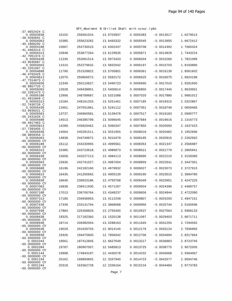
SFY_Abutment B Drilled Shaft with scour.lp8o-37.6652424 C 0.00003938 10102. 256561024. 13.6703937 0.0005383 -0.0013517 1.6279514 -38.9260691 C 0.00004063 10385. 255623282. 13.6493332 0.0005545 -0.0013955 1.6672412 -40.1866292 C 0.00004188 10667. 254730015. 13.6302447 0.0005708 -0.0014392 1.7060324 -41.4463214 C 0.00004313 10948. 253877264. 13.6129635 0.0005871 -0.0014829 1.7443224 -42.7051374 C 0.00004438 11230. 253061514. 13.5973433 0.0006034 -0.0015266 1.7821089 -43.9630687 C 0.00004563 11510. 252279632. 13.5832542 0.0006197 -0.0015703 1.8193890 -45.2201067 C 0.00004688 11790. 251528822. 13.5705801 0.0006361 -0.0016139 1.8561602 -46.4762425 C 0.00004813 12070. 250806572. 13.5592172 0.0006525 -0.0016575 1.8924198 -47.7314673 C 0.00004938 12349. 250110627. 13.5490723 0.0006690 -0.0017010 1.9281650 -48.9857720 C 0.00005063 12628. 249438951. 13.5400614 0.0006855 -0.0017445 1.9633931 -50.2391473 C 0.00005188 12906. 248789687. 13.5321088 0.0007020 -0.0017880 1.9981012 -51.4915849 C 0.00005313 13184. 248161203. 13.5251461 0.0007185 -0.0018315 2.0322867 -52.7430726 C 0.00005438 13461. 247551961. 13.5191112 0.0007351 -0.0018749 2.0659465 -53.9936021 C 0.00005563 13737. 246960581. 13.5139478 0.0007517 -0.0019183 2.0990777 -55.2431634 C 0.00005688 14013. 246385799. 13.5096045 0.0007684 -0.0019616 2.1316773 -56.4917463 C 0.00005813 14289. 245826462. 13.5060347 0.0007850 -0.0020050 2.1637423 -57.7393405 C 0.00005938 14564. 245281511. 13.5031955 0.0008018 -0.0020482 2.1952696 -58.9859354 C 0.00006063 14838. 244749972. 13.5010479 0.0008185 -0.0020915 2.2262562 -60.0000000 CY 0.00006188 15112. 244230950. 13.4995561 0.0008353 -0.0021347 2.2566987 -60.0000000 CY 0.00006313 15385. 243723618. 13.4986873 0.0008521 -0.0021779 2.2865941 -60.0000000 CY 0.00006438 15658. 243227213. 13.4984113 0.0008690 -0.0022210 2.3159390 -60.0000000 CY 0.00006563 15930. 242741027. 13.4987004 0.0008859 -0.0022641 2.3447301 -60.0000000 CY 0.00006688 16196. 242182160. 13.4979932 0.0009027 -0.0023073 2.3727915 -60.0000000 CY 0.00006813 16435. 241250692. 13.4905139 0.0009190 -0.0023510 2.3994780 -60.0000000 CY 0.00006938 16645. 239923186. 13.4755768 0.0009349 -0.0023951 2.4247225 -60.0000000 CY 0.00007063 16838. 238411930. 13.4571267 0.0009504 -0.0024396 2.4489757 -60.0000000 CY 0.00007188 17013. 236706764. 13.4348237 0.0009656 -0.0024844 2.4722090 -60.0000000 CY 0.00007313 17180. 234936903. 13.4112248 0.0009807 -0.0025293 2.4947151 -60.0000000 CY 0.00007438 17339. 233131794. 13.3868588 0.0009956 -0.0025744 2.5165596 -60.0000000 CY 0.00007938 17884. 225308829. 13.2755400 0.0010537 -0.0027563 2.5968133 -60.0000000 CY 0.00008438 18325. 217182360. 13.1520138 0.0011097 -0.0029403 2.6671711 -60.0000000 CY 0.00008938 18714. 209382054. 13.0288163 0.0011645 -0.0031255 2.7294592 -60.0000000 CY 0.00009438 19029. 201626703. 12.9014145 0.0012176 -0.0033124 2.7836965 -60.0000000 CY 0.00009938 19326. 194475600. 12.7856042 0.0012706 -0.0034994 2.8317664 -60.0000000 CY 0.0001044 19561. 187412845. 12.6627649 0.0013217 -0.0036883 2.8723745 -60.0000000 CY 0.0001094 19787. 180907007. 12.5485813 0.0013725 -0.0038775 2.9072005 -60.0000000 CY 0.0001144 19998. 174843197. 12.4430278 0.0014232 -0.0040668 2.9364067 -60.0000000 CY 0.0001194 20162. 168893802. 12.3337940 0.0014723 -0.0042577 2.9594746 -60.0000000 CY 0.0001244 20318. 163362728. 12.2336164 0.0015216 -0.0044484 2.9773783 -60.0000000 CY
Page 7
Page 94 of 140 Pages

SFY_Abutment B Drilled Shaft with scour.lp8o 0.0001294 20471. 158226530. 12.1377728 0.0015703 -0.0046397 2.9900062 -60.0000000 CY 0.0001344 20614. 153407167. 12.0488158 0.0016191 -0.0048309 2.9975431 -60.0000000 CY 0.0001394 20728. 148723307. 11.9580539 0.0016667 -0.0050233 2.9999999 -60.0000000 CY 0.0001444 20829. 144270527. 11.8714659 0.0017139 -0.0052161 2.9993757 -60.0000000 CY 0.0001494 20928. 140100578. 11.7925952 0.0017615 -0.0054085 2.9970426 -60.0000000 CY 0.0001544 21023. 136182269. 11.7177913 0.0018089 -0.0056011 2.9998904 -60.0000000 CY 0.0001594 21116. 132491843. 11.6472900 0.0018563 -0.0057937 2.9977213 -60.0000000 CY 0.0001644 21204. 128997237. 11.5812783 0.0019037 -0.0059863 2.9999590 -60.0000000 CY 0.0001694 21277. 125619898. 11.5150513 0.0019504 -0.0061796 2.9972956 -60.0000000 CY 0.0001744 21336. 122354505. 11.4480355 0.0019963 -0.0063737 2.9997810 -60.0000000 CY 0.0001794 21392. 119259641. 11.3857833 0.0020423 -0.0065677 2.9955723 -60.0000000 CY 0.0001844 21448. 116327017. 11.3280787 0.0020886 -0.0067614 2.9988707 -60.0000000 CY 0.0001894 21502. 113544263. 11.2739610 0.0021350 -0.0069550 2.9996889 60.0000000 CY 0.0001944 21555. 110892264. 11.2199582 0.0021809 -0.0071491 2.9960694 60.0000000 CY 0.0001994 21606. 108370435. 11.1695049 0.0022269 -0.0073431 2.9990747 60.0000000 CY 0.0002044 21657. 105967750. 11.1222487 0.0022731 -0.0075369 2.9996051 60.0000000 CY 0.0002094 21707. 103673437. 11.0782073 0.0023195 -0.0077305 2.9948308 60.0000000 CY 0.0002144 21749. 101453584. 11.0334074 0.0023653 -0.0079247 2.9981993 60.0000000 CY 0.0002194 21789. 99320986. 10.9899053 0.0024109 -0.0081191 2.9998272 60.0000000 CY 0.0002244 21819. 97245114. 10.9448109 0.0024557 -0.0083143 2.9970020 60.0000000 CY 0.0002294 21849. 95254744. 10.9019716 0.0025006 -0.0085094 2.9946834 60.0000000 CY 0.0002344 21878. 93345541. 10.8610953 0.0025456 -0.0087044 2.9977998 60.0000000 CY 0.0002394 21906. 91514963. 10.8223938 0.0025906 -0.0088994 2.9995682 60.0000000 CY 0.0002444 21934. 89755990. 10.7842209 0.0026354 -0.0090946 2.9990060 60.0000000 CY 0.0002494 21961. 88062890. 10.7458786 0.0026798 -0.0092902 2.9940293 60.0000000 CY 0.0002544 21987. 86435673. 10.7093966 0.0027242 -0.0094858 2.9946000 60.0000000 CY 0.0002594 22013. 84870519. 10.6746723 0.0027687 -0.0096813 2.9974565 60.0000000 CY 0.0002644 22039. 83363894. 10.6416111 0.0028134 -0.0098766 2.9992556 60.0000000 CY 0.0002694 22065. 81912528. 10.6101254 0.0028581 -0.0100719 2.9999837 60.0000000 CY 0.0002744 22091. 80512664. 10.5804040 0.0029030 -0.0102670 2.9962009 60.0000000 CY 0.0003044 22217. 72993142. 10.4231353 0.0031725 -0.0114375 2.9989753 60.0000000 CYT 0.0003344 22282. 66637159. 10.2917929 0.0034413 -0.0126087 2.9983775 60.0000000 CYT 0.0003644 22319. 61253523. 10.1923999 0.0037139 -0.0137761 2.9873795 60.0000000 CYT 0.0003944 22319. 56593984. 10.1739578 0.0040124 -0.0149176 2.9973940 60.0000000 CYT
Axial Thrust Force = 109.425 kips
Bending Bending Bending Depth to Max Comp Max Tens Max Conc Max Steel Run Curvature Moment Stiffness N Axis Strain Strain Stress Stress Msg rad/in. in-kip kip-in2 in in/in in/in ksi ksi ------------- ------------- ------------- ------------- ------------- ------------- -------------
Page 8
Page 95 of 140 Pages

SFY_Abutment B Drilled Shaft with scour.lp8o------------- --- 6.25000E-07 655.5238720 1048838195. 48.6964620 0.00003044 4.35289E-07 0.1102056 0.8782734 0.00000125 1310. 1048210825. 36.3822907 0.00004548 -0.00001452 0.1636420 1.3101580 0.00000188 1962. 1046386312. 32.2822412 0.00006053 -0.00002947 0.2166108 1.7422969 0.00000250 2610. 1044049574. 30.2333095 0.00007558 -0.00004442 0.2690899 2.1745149 0.00000313 3255. 1041483335. 29.0043866 0.00009064 -0.00005936 0.3210742 2.6067725 0.00000375 3895. 1038797123. 28.1853434 0.0001057 -0.00007430 0.3725621 3.0390561 0.00000438 4533. 1036040807. 27.6004716 0.0001208 -0.00008925 0.4235527 3.4713599 0.00000500 5166. 1033240095. 27.1619372 0.0001358 -0.0001042 0.4740458 3.9036809 0.00000563 5166. 918435640. 20.1456470 0.0001133 -0.0001567 0.3971644 -4.5045915 C 0.00000625 5166. 826592076. 19.5212877 0.0001220 -0.0001780 0.4262954 -5.1182666 C 0.00000688 5166. 751447342. 18.9939682 0.0001306 -0.0001994 0.4548792 -5.7352276 C 0.00000750 5166. 688826730. 18.5416066 0.0001391 -0.0002209 0.4829771 -6.3550006 C 0.00000813 5166. 635840058. 18.1491578 0.0001475 -0.0002425 0.5106559 -6.9770547 C 0.00000875 5166. 590422911. 17.8061434 0.0001558 -0.0002642 0.5379886 -7.6007911 C 0.00000938 5166. 551061384. 17.5051150 0.0001641 -0.0002859 0.5650542 -8.2255468 C 0.00001000 5166. 516620047. 17.2346151 0.0001723 -0.0003077 0.5917365 -8.8523616 C 0.00001063 5166. 486230633. 16.9951156 0.0001806 -0.0003294 0.6182432 -9.4794300 C 0.00001125 5166. 459217820. 16.7772641 0.0001887 -0.0003513 0.6444215 -10.1081176 C 0.00001188 5166. 435048461. 16.5828402 0.0001969 -0.0003731 0.6704742 -10.7366344 C 0.00001250 5166. 413296038. 16.4032761 0.0002050 -0.0003950 0.6961976 -11.3668124 C 0.00001313 5166. 393615274. 16.2405731 0.0002132 -0.0004168 0.7217681 -11.9970818 C 0.00001375 5166. 375723671. 16.0930897 0.0002213 -0.0004387 0.7472147 -12.6271805 C 0.00001438 5166. 359387859. 15.9546816 0.0002293 -0.0004607 0.7723478 -13.2588421 C 0.00001500 5166. 344413365. 15.8277898 0.0002374 -0.0004826 0.7973391 -13.8905114 C 0.00001563 5166. 330636830. 15.7114286 0.0002455 -0.0005045 0.8222079 -14.5220089 C 0.00001625 5166. 317920029. 15.6043841 0.0002536 -0.0005264 0.8469541 -15.1533340 C 0.00001688 5229. 309870134. 15.5022774 0.0002616 -0.0005484 0.8714026 -15.7861230 C 0.00001750 5375. 307132355. 15.4076627 0.0002696 -0.0005704 0.8957223 -16.4188111 C 0.00001813 5520. 304577073. 15.3199052 0.0002777 -0.0005923 0.9199206 -17.0513248 C 0.00001875 5666. 302186020. 15.2383203 0.0002857 -0.0006143 0.9439974 -17.6836633 C 0.00001938 5811. 299943280. 15.1623117 0.0002938 -0.0006362 0.9679523 -18.3158260 C 0.00002000 5957. 297829740. 15.0903083 0.0003018 -0.0006582 0.9917221 -18.9484211 C 0.00002063 6102. 295831585. 15.0215132 0.0003098 -0.0006802 1.0152808 -19.5817074 C 0.00002125 6246. 293945635. 14.9570557 0.0003178 -0.0007022 1.0387189 -20.2148144 C 0.00002188 6391. 292162253. 14.8965650 0.0003259 -0.0007241 1.0620360 -20.8477415 C 0.00002250 6536. 290472875. 14.8397116 0.0003339 -0.0007461 1.0852320 -21.4804881 C 0.00002313 6680. 288869862. 14.7862016 0.0003419 -0.0007681 1.1083066 -22.1130535 C 0.00002375 6824. 287346379. 14.7357721 0.0003500 -0.0007900 1.1312595 -22.7454369 C 0.00002438 6969. 285896290. 14.6881871 0.0003580 -0.0008120 1.1540904 -23.3776377 C
Page 9
Page 96 of 140 Pages

SFY_Abutment B Drilled Shaft with scour.lp8o 0.00002563 7257. 283189337. 14.5992500 0.0003741 -0.0008559 1.1992780 -24.6425823 C 0.00002688 7544. 280711125. 14.5179172 0.0003902 -0.0008998 1.2438551 -25.9080482 C 0.00002813 7831. 278436858. 14.4447421 0.0004063 -0.0009437 1.2879459 -27.1727572 C 0.00002938 8117. 276340386. 14.3786905 0.0004224 -0.0009876 1.3315483 -28.4367030 C 0.00003063 8403. 274399828. 14.3188973 0.0004385 -0.0010315 1.3746600 -29.6998792 C 0.00003188 8689. 272596733. 14.2646333 0.0004547 -0.0010753 1.4172788 -30.9622795 C 0.00003313 8974. 270915433. 14.2152791 0.0004709 -0.0011191 1.4594023 -32.2238974 C 0.00003438 9259. 269342538. 14.1703060 0.0004871 -0.0011629 1.5010284 -33.4847261 C 0.00003563 9543. 267863773. 14.1280559 0.0005033 -0.0012067 1.5420450 -34.7460021 C 0.00003688 9826. 266471454. 14.0890650 0.0005195 -0.0012505 1.5825292 -36.0068560 C 0.00003813 10109. 265157832. 14.0533819 0.0005358 -0.0012942 1.6225148 -37.2668795 C 0.00003938 10392. 263915314. 14.0206981 0.0005521 -0.0013379 1.6619991 -38.5260652 C 0.00004063 10674. 262737242. 13.9907434 0.0005684 -0.0013816 1.7009797 -39.7844053 C 0.00004188 10955. 261617752. 13.9632798 0.0005847 -0.0014253 1.7394542 -41.0418920 C 0.00004313 11236. 260551657. 13.9380970 0.0006011 -0.0014689 1.7774200 -42.2985173 C 0.00004438 11517. 259534353. 13.9150087 0.0006175 -0.0015125 1.8148744 -43.5542731 C 0.00004563 11797. 258561740. 13.8938488 0.0006339 -0.0015561 1.8518149 -44.8091512 C 0.00004688 12076. 257630155. 13.8744692 0.0006504 -0.0015996 1.8882389 -46.0631432 C 0.00004813 12355. 256736311. 13.8567375 0.0006669 -0.0016431 1.9241437 -47.3162406 C 0.00004938 12634. 255877255. 13.8405344 0.0006834 -0.0016866 1.9595265 -48.5684347 C 0.00005063 12912. 255050324. 13.8257528 0.0006999 -0.0017301 1.9943846 -49.8197165 C 0.00005188 13189. 254253110. 13.8122959 0.0007165 -0.0017735 2.0287152 -51.0700772 C 0.00005313 13466. 253483429. 13.8000762 0.0007331 -0.0018169 2.0625154 -52.3195074 C 0.00005438 13743. 252739298. 13.7890142 0.0007498 -0.0018602 2.0957824 -53.5679980 C 0.00005563 14019. 252018912. 13.7790379 0.0007665 -0.0019035 2.1285132 -54.8155393 C 0.00005688 14294. 251320619. 13.7700815 0.0007832 -0.0019468 2.1607049 -56.0621217 C 0.00005813 14569. 250642894. 13.7620850 0.0007999 -0.0019901 2.1923544 -57.3077369 C 0.00005938 14843. 249984394. 13.7549938 0.0008167 -0.0020333 2.2234588 -58.5523713 C 0.00006063 15116. 249343826. 13.7487576 0.0008335 -0.0020765 2.2540149 -59.7960165 C 0.00006188 15390. 248720020. 13.7433304 0.0008504 -0.0021196 2.2840195 -60.0000000 CY 0.00006313 15662. 248111898. 13.7386701 0.0008673 -0.0021627 2.3134695 -60.0000000 CY 0.00006438 15934. 247518466. 13.7347377 0.0008842 -0.0022058 2.3423616 -60.0000000 CY 0.00006563 16205. 246938801. 13.7314976 0.0009011 -0.0022489 2.3706925 -60.0000000 CY 0.00006688 16473. 246332491. 13.7282026 0.0009181 -0.0022919 2.3983803 -60.0000000 CY 0.00006813 16724. 245490774. 13.7209904 0.0009347 -0.0023353 2.4250028 -60.0000000 CY 0.00006938 16945. 244246286. 13.7065915 0.0009509 -0.0023791 2.4502111 -60.0000000 CY 0.00007063 17145. 242766356. 13.6879589 0.0009667 -0.0024233 2.4743393 -60.0000000 CY 0.00007188 17328. 241081609. 13.6648476 0.0009822 -0.0024678 2.4973723 -60.0000000 CY 0.00007313 17494. 239236448. 13.6381478 0.0009973 -0.0025127 2.5194187 -60.0000000 CY 0.00007438 17657. 237410910. 13.6119054 0.0010124 -0.0025576 2.5409236
Page 10
Page 97 of 140 Pages
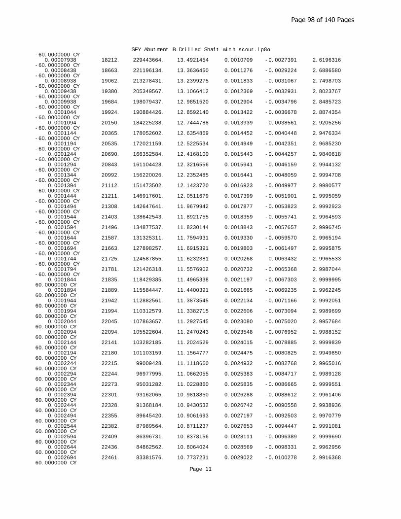
SFY_Abutment B Drilled Shaft with scour.lp8o-60.0000000 CY 0.00007938 18212. 229443664. 13.4921454 0.0010709 -0.0027391 2.6196316 -60.0000000 CY 0.00008438 18663. 221196134. 13.3636450 0.0011276 -0.0029224 2.6886580 -60.0000000 CY 0.00008938 19062. 213278431. 13.2399275 0.0011833 -0.0031067 2.7498703 -60.0000000 CY 0.00009438 19380. 205349567. 13.1066412 0.0012369 -0.0032931 2.8023767 -60.0000000 CY 0.00009938 19684. 198079437. 12.9851520 0.0012904 -0.0034796 2.8485723 -60.0000000 CY 0.0001044 19924. 190884426. 12.8592140 0.0013422 -0.0036678 2.8874354 -60.0000000 CY 0.0001094 20150. 184225238. 12.7444788 0.0013939 -0.0038561 2.9205256 -60.0000000 CY 0.0001144 20365. 178052602. 12.6354869 0.0014452 -0.0040448 2.9476334 -60.0000000 CY 0.0001194 20535. 172021159. 12.5225534 0.0014949 -0.0042351 2.9685230 -60.0000000 CY 0.0001244 20690. 166352584. 12.4168100 0.0015443 -0.0044257 2.9840618 -60.0000000 CY 0.0001294 20843. 161104428. 12.3216556 0.0015941 -0.0046159 2.9944132 -60.0000000 CY 0.0001344 20992. 156220026. 12.2352485 0.0016441 -0.0048059 2.9994708 -60.0000000 CY 0.0001394 21112. 151473502. 12.1423720 0.0016923 -0.0049977 2.9980577 -60.0000000 CY 0.0001444 21211. 146917601. 12.0511679 0.0017399 -0.0051901 2.9995059 -60.0000000 CY 0.0001494 21308. 142647641. 11.9679942 0.0017877 -0.0053823 2.9992923 -60.0000000 CY 0.0001544 21403. 138642543. 11.8921755 0.0018359 -0.0055741 2.9964593 -60.0000000 CY 0.0001594 21496. 134877537. 11.8230144 0.0018843 -0.0057657 2.9996745 -60.0000000 CY 0.0001644 21587. 131325311. 11.7594931 0.0019330 -0.0059570 2.9965194 -60.0000000 CY 0.0001694 21663. 127898257. 11.6915391 0.0019803 -0.0061497 2.9995875 -60.0000000 CY 0.0001744 21725. 124587855. 11.6232381 0.0020268 -0.0063432 2.9965533 -60.0000000 CY 0.0001794 21781. 121426318. 11.5576902 0.0020732 -0.0065368 2.9987044 -60.0000000 CY 0.0001844 21835. 118429385. 11.4965338 0.0021197 -0.0067303 2.9999995 60.0000000 CY 0.0001894 21889. 115584447. 11.4400391 0.0021665 -0.0069235 2.9962245 60.0000000 CY 0.0001944 21942. 112882561. 11.3873545 0.0022134 -0.0071166 2.9992051 60.0000000 CY 0.0001994 21994. 110312579. 11.3382715 0.0022606 -0.0073094 2.9989699 60.0000000 CY 0.0002044 22045. 107863657. 11.2927545 0.0023080 -0.0075020 2.9957684 60.0000000 CY 0.0002094 22094. 105522604. 11.2470243 0.0023548 -0.0076952 2.9988152 60.0000000 CY 0.0002144 22141. 103282185. 11.2024529 0.0024015 -0.0078885 2.9999839 60.0000000 CY 0.0002194 22180. 101103159. 11.1564777 0.0024475 -0.0080825 2.9949850 60.0000000 CY 0.0002244 22215. 99009428. 11.1118660 0.0024932 -0.0082768 2.9965016 60.0000000 CY 0.0002294 22244. 96977995. 11.0662055 0.0025383 -0.0084717 2.9989128 60.0000000 CY 0.0002344 22273. 95031282. 11.0228860 0.0025835 -0.0086665 2.9999551 60.0000000 CY 0.0002394 22301. 93162065. 10.9818850 0.0026288 -0.0088612 2.9961406 60.0000000 CY 0.0002444 22328. 91368184. 10.9430532 0.0026742 -0.0090558 2.9938936 60.0000000 CY 0.0002494 22355. 89645420. 10.9061693 0.0027197 -0.0092503 2.9970779 60.0000000 CY 0.0002544 22382. 87989564. 10.8711237 0.0027653 -0.0094447 2.9991081 60.0000000 CY 0.0002594 22409. 86396731. 10.8378156 0.0028111 -0.0096389 2.9999690 60.0000000 CY 0.0002644 22436. 84862562. 10.8064024 0.0028569 -0.0098331 2.9962956 60.0000000 CY 0.0002694 22461. 83381576. 10.7737231 0.0029022 -0.0100278 2.9916368 60.0000000 CY
Page 11
Page 98 of 140 Pages

SFY_Abutment B Drilled Shaft with scour.lp8o 0.0002744 22485. 81950467. 10.7426078 0.0029475 -0.0102225 2.9946622 60.0000000 CY 0.0003044 22610. 74283314. 10.5850679 0.0032218 -0.0113882 2.9905097 60.0000000 CYT 0.0003344 22672. 67802967. 10.4577708 0.0034968 -0.0125532 2.9963633 60.0000000 CYT 0.0003644 22707. 62317059. 10.3672904 0.0037776 -0.0137124 2.9979954 60.0000000 CYT 0.0003944 22707. 57576617. 10.4388507 0.0041168 -0.0148132 2.9941255 60.0000000 CYT
Axial Thrust Force = 116.465 kips
Bending Bending Bending Depth to Max Comp Max Tens Max Conc Max Steel Run Curvature Moment Stiffness N Axis Strain Strain Stress Stress Msg rad/in. in-kip kip-in2 in in/in in/in ksi ksi ------------- ------------- ------------- ------------- ------------- ------------- ------------- ------------- --- 6.25000E-07 655.1643340 1048262934. 50.2911383 0.00003143 0.00000143 0.1137974 0.9071769 0.00000125 1310. 1047760474. 37.1805704 0.00004648 -0.00001352 0.1672046 1.3390957 0.00000188 1961. 1046058449. 32.8158442 0.00006153 -0.00002847 0.2201493 1.7713115 0.00000250 2609. 1043794956. 30.6347698 0.00007659 -0.00004341 0.2726059 2.2036208 0.00000313 3254. 1041275539. 29.3266312 0.00009165 -0.00005835 0.3245683 2.6359760 0.00000375 3895. 1038621504. 28.4548110 0.0001067 -0.00007329 0.3760344 3.0683607 0.00000438 4532. 1035888544. 27.8322602 0.0001218 -0.00008823 0.4270033 3.5007680 0.00000500 5166. 1033105529. 27.3654791 0.0001368 -0.0001032 0.4774746 3.9331945 0.00000563 5166. 918316026. 20.5464155 0.0001156 -0.0001544 0.4048713 -4.4392160 C 0.00000625 5166. 826484423. 19.8958314 0.0001243 -0.0001757 0.4342530 -5.0503806 C 0.00000688 5166. 751349476. 19.3444157 0.0001330 -0.0001970 0.4630236 -5.6653571 C 0.00000750 5166. 688737020. 18.8724876 0.0001415 -0.0002185 0.4913192 -6.2830339 C 0.00000813 5166. 635757249. 18.4639928 0.0001500 -0.0002400 0.5192072 -6.9028717 C 0.00000875 5166. 590346017. 18.1044997 0.0001584 -0.0002616 0.5466675 -7.5250832 C 0.00000938 5166. 550989616. 17.7872689 0.0001668 -0.0002832 0.5737993 -8.1488363 C 0.00001000 5166. 516552765. 17.5071124 0.0001751 -0.0003049 0.6006956 -8.7733374 C 0.00001063 5166. 486167308. 17.2532137 0.0001833 -0.0003267 0.6272094 -9.3999035 C 0.00001125 5166. 459158013. 17.0276759 0.0001916 -0.0003484 0.6535813 -10.0264207 C 0.00001188 5166. 434991802. 16.8203134 0.0001997 -0.0003703 0.6795924 -10.6548545 C 0.00001250 5166. 413242212. 16.6341609 0.0002079 -0.0003921 0.7054776 -11.2831166 C 0.00001313 5166. 393564011. 16.4630557 0.0002161 -0.0004139 0.7311051 -11.9123994 C 0.00001375 5166. 375674738. 16.3056866 0.0002242 -0.0004358 0.7565092 -12.5424074 C 0.00001438 5166. 359341054. 16.1624139 0.0002323 -0.0004577 0.7817891 -13.1722437 C 0.00001500 5166. 344368510. 16.0298068 0.0002404 -0.0004796 0.8068657 -13.8026340 C 0.00001563 5166. 330593769. 15.9055834 0.0002485 -0.0005015 0.8316912 -14.4340325 C 0.00001625 5166. 317878624. 15.7912825 0.0002566 -0.0005234 0.8563939 -15.0652581 C 0.00001688 5307. 314502563. 15.6858028 0.0002647 -0.0005453 0.8809736 -15.6963102 C 0.00001750 5453. 311613468. 15.5877812 0.0002728 -0.0005672 0.9054074 -16.3274010 C 0.00001813 5599. 308899913. 15.4940199 0.0002808 -0.0005892 0.9295613
Page 12
Page 99 of 140 Pages
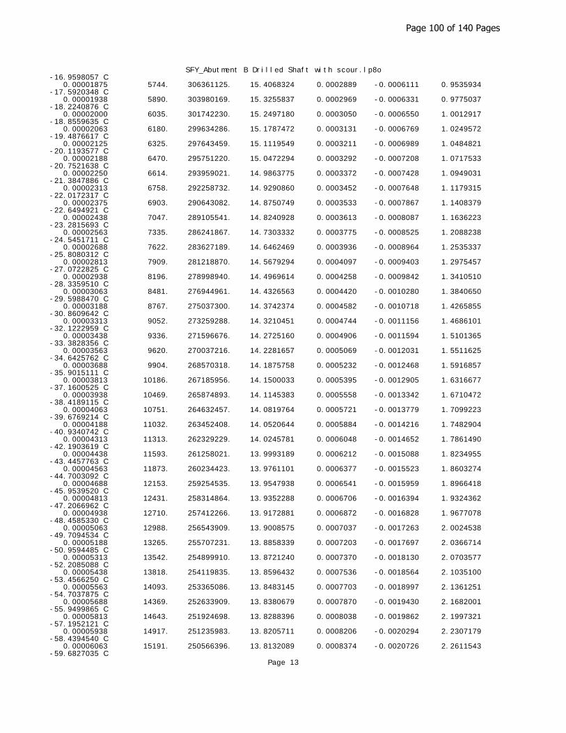
SFY_Abutment B Drilled Shaft with scour.lp8o-16.9598057 C 0.00001875 5744. 306361125. 15.4068324 0.0002889 -0.0006111 0.9535934 -17.5920348 C 0.00001938 5890. 303980169. 15.3255837 0.0002969 -0.0006331 0.9775037 -18.2240876 C 0.00002000 6035. 301742230. 15.2497180 0.0003050 -0.0006550 1.0012917 -18.8559635 C 0.00002063 6180. 299634286. 15.1787472 0.0003131 -0.0006769 1.0249572 -19.4876617 C 0.00002125 6325. 297643459. 15.1119549 0.0003211 -0.0006989 1.0484821 -20.1193577 C 0.00002188 6470. 295751220. 15.0472294 0.0003292 -0.0007208 1.0717533 -20.7521638 C 0.00002250 6614. 293959021. 14.9863775 0.0003372 -0.0007428 1.0949031 -21.3847886 C 0.00002313 6758. 292258732. 14.9290860 0.0003452 -0.0007648 1.1179315 -22.0172317 C 0.00002375 6903. 290643082. 14.8750749 0.0003533 -0.0007867 1.1408379 -22.6494921 C 0.00002438 7047. 289105541. 14.8240928 0.0003613 -0.0008087 1.1636223 -23.2815693 C 0.00002563 7335. 286241867. 14.7303332 0.0003775 -0.0008525 1.2088238 -24.5451711 C 0.00002688 7622. 283627189. 14.6462469 0.0003936 -0.0008964 1.2535337 -25.8080312 C 0.00002813 7909. 281218870. 14.5679294 0.0004097 -0.0009403 1.2975457 -27.0722825 C 0.00002938 8196. 278998940. 14.4969614 0.0004258 -0.0009842 1.3410510 -28.3359510 C 0.00003063 8481. 276944961. 14.4326563 0.0004420 -0.0010280 1.3840650 -29.5988470 C 0.00003188 8767. 275037300. 14.3742374 0.0004582 -0.0010718 1.4265855 -30.8609642 C 0.00003313 9052. 273259288. 14.3210451 0.0004744 -0.0011156 1.4686101 -32.1222959 C 0.00003438 9336. 271596676. 14.2725160 0.0004906 -0.0011594 1.5101365 -33.3828356 C 0.00003563 9620. 270037216. 14.2281657 0.0005069 -0.0012031 1.5511625 -34.6425762 C 0.00003688 9904. 268570318. 14.1875758 0.0005232 -0.0012468 1.5916857 -35.9015111 C 0.00003813 10186. 267185956. 14.1500033 0.0005395 -0.0012905 1.6316677 -37.1600525 C 0.00003938 10469. 265874893. 14.1145383 0.0005558 -0.0013342 1.6710472 -38.4189115 C 0.00004063 10751. 264632457. 14.0819764 0.0005721 -0.0013779 1.7099223 -39.6769214 C 0.00004188 11032. 263452408. 14.0520644 0.0005884 -0.0014216 1.7482904 -40.9340742 C 0.00004313 11313. 262329229. 14.0245781 0.0006048 -0.0014652 1.7861490 -42.1903619 C 0.00004438 11593. 261258021. 13.9993189 0.0006212 -0.0015088 1.8234955 -43.4457763 C 0.00004563 11873. 260234423. 13.9761101 0.0006377 -0.0015523 1.8603274 -44.7003092 C 0.00004688 12153. 259254535. 13.9547938 0.0006541 -0.0015959 1.8966418 -45.9539520 C 0.00004813 12431. 258314864. 13.9352288 0.0006706 -0.0016394 1.9324362 -47.2066962 C 0.00004938 12710. 257412266. 13.9172881 0.0006872 -0.0016828 1.9677078 -48.4585330 C 0.00005063 12988. 256543909. 13.9008575 0.0007037 -0.0017263 2.0024538 -49.7094534 C 0.00005188 13265. 255707231. 13.8858339 0.0007203 -0.0017697 2.0366714 -50.9594485 C 0.00005313 13542. 254899910. 13.8721240 0.0007370 -0.0018130 2.0703577 -52.2085088 C 0.00005438 13818. 254119835. 13.8596432 0.0007536 -0.0018564 2.1035100 -53.4566250 C 0.00005563 14093. 253365086. 13.8483145 0.0007703 -0.0018997 2.1361251 -54.7037875 C 0.00005688 14369. 252633909. 13.8380679 0.0007870 -0.0019430 2.1682001 -55.9499865 C 0.00005813 14643. 251924698. 13.8288396 0.0008038 -0.0019862 2.1997321 -57.1952121 C 0.00005938 14917. 251235983. 13.8205711 0.0008206 -0.0020294 2.2307179 -58.4394540 C 0.00006063 15191. 250566396. 13.8132089 0.0008374 -0.0020726 2.2611543 -59.6827035 C
Page 13
Page 100 of 140 Pages

SFY_Abutment B Drilled Shaft with scour.lp8o 0.00006188 15463. 249914730. 13.8067040 0.0008543 -0.0021157 2.2910383 -60.0000000 CY 0.00006313 15736. 249279819. 13.8010114 0.0008712 -0.0021588 2.3203666 -60.0000000 CY 0.00006438 16008. 248660604. 13.7960895 0.0008881 -0.0022019 2.3491360 -60.0000000 CY 0.00006563 16279. 248056106. 13.7919003 0.0009051 -0.0022449 2.3773431 -60.0000000 CY 0.00006688 16547. 247436901. 13.7878926 0.0009221 -0.0022879 2.4049281 -60.0000000 CY 0.00006813 16800. 246606976. 13.7804368 0.0009388 -0.0023312 2.4314966 -60.0000000 CY 0.00006938 17023. 245381245. 13.7659404 0.0009550 -0.0023750 2.4566660 -60.0000000 CY 0.00007063 17225. 243898908. 13.7468270 0.0009709 -0.0024191 2.4807120 -60.0000000 CY 0.00007188 17410. 242229557. 13.7242583 0.0009864 -0.0024636 2.5037716 -60.0000000 CY 0.00007313 17578. 240379761. 13.6982281 0.0010017 -0.0025083 2.5258555 -60.0000000 CY 0.00007438 17742. 238551030. 13.6723651 0.0010169 -0.0025531 2.5473618 -60.0000000 CY 0.00007938 18299. 230543488. 13.5503100 0.0010756 -0.0027344 2.6256457 -60.0000000 CY 0.00008438 18754. 222263913. 13.4198906 0.0011323 -0.0029177 2.6942480 -60.0000000 CY 0.00008938 19153. 214304094. 13.2941873 0.0011882 -0.0031018 2.7549871 -60.0000000 CY 0.00009438 19474. 206341753. 13.1618699 0.0012422 -0.0032878 2.8072598 -60.0000000 CY 0.00009938 19779. 199033577. 13.0386648 0.0012957 -0.0034743 2.8529288 -60.0000000 CY 0.0001044 20020. 191806972. 12.9112398 0.0013476 -0.0036624 2.8912657 -60.0000000 CY 0.0001094 20245. 185101468. 12.7945832 0.0013994 -0.0038506 2.9237680 -60.0000000 CY 0.0001144 20463. 178907870. 12.6873723 0.0014511 -0.0040389 2.9504736 -60.0000000 CY 0.0001194 20635. 172854641. 12.5734651 0.0015010 -0.0042290 2.9707681 -60.0000000 CY 0.0001244 20789. 167149056. 12.4661209 0.0015505 -0.0044195 2.9856614 -60.0000000 CY 0.0001294 20941. 161866656. 12.3695083 0.0016003 -0.0046097 2.9953514 -60.0000000 CY 0.0001344 21090. 156952119. 12.2821230 0.0016504 -0.0047996 2.9997334 -60.0000000 CY 0.0001394 21214. 152206301. 12.1921975 0.0016993 -0.0049907 2.9986525 -60.0000000 CY 0.0001444 21313. 147622457. 12.0998048 0.0017469 -0.0051831 2.9980473 -60.0000000 CY 0.0001494 21409. 143326285. 12.0154220 0.0017948 -0.0053752 2.9996356 -60.0000000 CY 0.0001544 21504. 139296146. 11.9385456 0.0018430 -0.0055670 2.9972012 -60.0000000 CY 0.0001594 21597. 135508295. 11.8683275 0.0018915 -0.0057585 2.9998922 -60.0000000 CY 0.0001644 21687. 131934832. 11.8039690 0.0019403 -0.0059497 2.9973739 -60.0000000 CY 0.0001694 21765. 128503693. 11.7392388 0.0019883 -0.0061417 2.9998621 -60.0000000 CY 0.0001744 21829. 125182706. 11.6707776 0.0020351 -0.0063349 2.9961109 -60.0000000 CY 0.0001794 21884. 122003690. 11.6042950 0.0020815 -0.0065285 2.9992639 -60.0000000 CY 0.0001844 21939. 118988986. 11.5423192 0.0021281 -0.0067219 2.9983785 60.0000000 CY 0.0001894 21992. 116127937. 11.4849273 0.0021750 -0.0069150 2.9972509 60.0000000 CY 0.0001944 22044. 113410790. 11.4313929 0.0022220 -0.0071080 2.9996345 60.0000000 CY 0.0001994 22096. 110825712. 11.3816245 0.0022692 -0.0073008 2.9971745 60.0000000 CY 0.0002044 22147. 108363172. 11.3353191 0.0023167 -0.0074933 2.9968833 60.0000000 CY 0.0002094 22197. 106013685. 11.2917604 0.0023642 -0.0076858 2.9994003 60.0000000 CY 0.0002144 22245. 103766022. 11.2481432 0.0024113 -0.0078787 2.9987512 60.0000000 CY 0.0002194 22284. 101577924. 11.2018006 0.0024574 -0.0080726 2.9942987
Page 14
Page 101 of 140 Pages

SFY_Abutment B Drilled Shaft with scour.lp8o60.0000000 CY 0.0002244 22321. 99479728. 11.1573073 0.0025034 -0.0082666 2.9976636 60.0000000 CY 0.0002294 22350. 97437327. 11.1108879 0.0025486 -0.0084614 2.9995113 60.0000000 CY 0.0002344 22378. 95480394. 11.0669767 0.0025938 -0.0086562 2.9991662 60.0000000 CY 0.0002394 22406. 93600890. 11.0253487 0.0026392 -0.0088508 2.9939796 60.0000000 CY 0.0002444 22433. 91797470. 10.9858224 0.0026847 -0.0090453 2.9955027 60.0000000 CY 0.0002494 22460. 90065541. 10.9482767 0.0027302 -0.0092398 2.9981576 60.0000000 CY 0.0002544 22487. 88400873. 10.9126004 0.0027759 -0.0094341 2.9996511 60.0000000 CY 0.0002594 22514. 86799307. 10.8787738 0.0028217 -0.0096283 2.9988839 60.0000000 CY 0.0002644 22540. 85256840. 10.8468318 0.0028676 -0.0098224 2.9940755 60.0000000 CY 0.0002694 22566. 83770499. 10.8165212 0.0029137 -0.0100163 2.9932462 60.0000000 CY 0.0002744 22590. 82332903. 10.7870815 0.0029597 -0.0102103 2.9963854 60.0000000 CY 0.0003044 22715. 74627167. 10.6293800 0.0032353 -0.0113747 2.9930915 60.0000000 CYT 0.0003344 22775. 68112663. 10.5024675 0.0035118 -0.0125382 2.9932589 60.0000000 CYT 0.0003644 22809. 62597466. 10.4105033 0.0037933 -0.0136967 2.9992116 60.0000000 CYT 0.0003944 22809. 57835694. 10.4833375 0.0041344 -0.0147956 2.9966310 60.0000000 CYT
Axial Thrust Force = 148.556 kips
Bending Bending Bending Depth to Max Comp Max Tens Max Conc Max Steel Run Curvature Moment Stiffness N Axis Strain Strain Stress Stress Msg rad/in. in-kip kip-in2 in in/in in/in ksi ksi ------------- ------------- ------------- ------------- ------------- ------------- ------------- ------------- --- 6.25000E-07 653.5228275 1045636524. 57.5717892 0.00003598 0.00000598 0.1301675 1.0391387 0.00000125 1307. 1045488302. 40.8235015 0.00005103 -0.00000897 0.1834340 1.4711519 0.00000188 1958. 1044348304. 35.2501084 0.00006609 -0.00002391 0.2362634 1.9036746 0.00000250 2606. 1042451855. 32.4658731 0.00008116 -0.00003884 0.2886141 2.3363758 0.00000313 3251. 1040173876. 30.7962591 0.00009624 -0.00005376 0.3404744 2.7691610 0.00000375 3891. 1037687833. 29.6836499 0.0001113 -0.00006869 0.3918398 3.2019969 0.00000438 4528. 1035077754. 28.8892165 0.0001264 -0.00008361 0.4427086 3.6348694 0.00000500 5162. 1032388209. 28.2935928 0.0001415 -0.00009853 0.4930799 4.0677710 0.00000563 5792. 1029644872. 27.8304848 0.0001565 -0.0001135 0.5429530 4.5006979 0.00000625 5792. 926680385. 21.5125989 0.0001345 -0.0001655 0.4684616 -4.7573414 C 0.00000688 5792. 842436713. 20.8664992 0.0001435 -0.0001865 0.4982452 -5.3618917 C 0.00000750 5792. 772233654. 20.3095659 0.0001523 -0.0002077 0.5273895 -5.9704694 C 0.00000813 5792. 712831065. 19.8260831 0.0001611 -0.0002289 0.5560336 -6.5819292 C 0.00000875 5792. 661914560. 19.4020685 0.0001698 -0.0002502 0.5842339 -7.1958251 C 0.00000938 5792. 617786923. 19.0257041 0.0001784 -0.0002716 0.6119977 -7.8121367 C 0.00001000 5792. 579175240. 18.6892869 0.0001869 -0.0002931 0.6393696 -8.4305068 C 0.00001063 5792. 545106109. 18.3886623 0.0001954 -0.0003146 0.6664536 -9.0500434 C 0.00001125 5792. 514822436. 18.1163809 0.0002038 -0.0003362 0.6931979 -9.6712307 C
Page 15
Page 102 of 140 Pages

SFY_Abutment B Drilled Shaft with scour.lp8o 0.00001188 5792. 487726518. 17.8693671 0.0002122 -0.0003578 0.7196590 -10.2935867 C 0.00001250 5792. 463340192. 17.6443119 0.0002206 -0.0003794 0.7458584 -10.9169369 C 0.00001313 5792. 441276374. 17.4387013 0.0002289 -0.0004011 0.7718237 -11.5410443 C 0.00001375 5792. 421218357. 17.2487058 0.0002372 -0.0004228 0.7975054 -12.1663785 C 0.00001438 5792. 402904515. 17.0756573 0.0002455 -0.0004445 0.8230575 -12.7915353 C 0.00001500 5792. 386116827. 16.9134845 0.0002537 -0.0004663 0.8482950 -13.4182342 C 0.00001563 5792. 370672154. 16.7636183 0.0002619 -0.0004881 0.8733532 -14.0452354 C 0.00001625 5792. 356415533. 16.6256558 0.0002702 -0.0005098 0.8982834 -14.6720596 C 0.00001688 5792. 343214957. 16.4961859 0.0002784 -0.0005316 0.9229775 -15.2997290 C 0.00001750 5806. 331768876. 16.3742519 0.0002865 -0.0005535 0.9474347 -15.9282671 C 0.00001813 5952. 328388330. 16.2610646 0.0002947 -0.0005753 0.9717654 -16.5566279 C 0.00001875 6098. 325226563. 16.1557504 0.0003029 -0.0005971 0.9959696 -17.1848107 C 0.00001938 6244. 322256879. 16.0567640 0.0003111 -0.0006189 1.0200015 -17.8132556 C 0.00002000 6389. 319449328. 15.9617960 0.0003192 -0.0006408 1.0437598 -18.4429583 C 0.00002063 6534. 316806069. 15.8728837 0.0003274 -0.0006626 1.0673929 -19.0724814 C 0.00002125 6679. 314312587. 15.7894937 0.0003355 -0.0006845 1.0909006 -19.7018245 C 0.00002188 6824. 311956023. 15.7111537 0.0003437 -0.0007063 1.1142826 -20.3309868 C 0.00002250 6969. 309724950. 15.6374440 0.0003518 -0.0007282 1.1375387 -20.9599677 C 0.00002313 7113. 307602526. 15.5668318 0.0003600 -0.0007500 1.1605915 -21.5895434 C 0.00002375 7258. 305579387. 15.4989212 0.0003681 -0.0007719 1.1834318 -22.2198180 C 0.00002438 7402. 303655079. 15.4347537 0.0003762 -0.0007938 1.2061474 -22.8499084 C 0.00002563 7689. 300073963. 15.3165565 0.0003925 -0.0008375 1.2512037 -24.1095339 C 0.00002688 7977. 296807935. 15.2103105 0.0004088 -0.0008812 1.2957581 -25.3684142 C 0.00002813 8264. 293813925. 15.1142197 0.0004251 -0.0009249 1.3397922 -26.6267145 C 0.00002938 8549. 291044411. 15.0241091 0.0004413 -0.0009687 1.3830758 -27.8868870 C 0.00003063 8835. 288485207. 14.9422235 0.0004576 -0.0010124 1.4258586 -29.1462877 C 0.00003188 9120. 286111459. 14.8676019 0.0004739 -0.0010561 1.4681382 -30.4049104 C 0.00003313 9404. 283902063. 14.7994288 0.0004902 -0.0010998 1.5099122 -31.6627486 C 0.00003438 9688. 281838982. 14.7370073 0.0005066 -0.0011434 1.5511784 -32.9197958 C 0.00003563 9972. 279906710. 14.6797382 0.0005230 -0.0011870 1.5919343 -34.1760454 C 0.00003688 10255. 278090302. 14.6266034 0.0005394 -0.0012306 1.6321318 -35.4320258 C 0.00003813 10537. 276375504. 14.5762654 0.0005557 -0.0012743 1.6716831 -36.6887664 C 0.00003938 10819. 274756899. 14.5298548 0.0005721 -0.0013179 1.7107236 -37.9446719 C 0.00004063 11100. 273225510. 14.4870154 0.0005885 -0.0013615 1.7492506 -39.1997348 C 0.00004188 11381. 271773431. 14.4474337 0.0006050 -0.0014050 1.7872617 -40.4539476 C 0.00004313 11661. 270393672. 14.4108327 0.0006215 -0.0014485 1.8247543 -41.7073023 C 0.00004438 11940. 269080027. 14.3769665 0.0006380 -0.0014920 1.8617257 -42.9597911 C 0.00004563 12220. 267826971. 14.3456166 0.0006545 -0.0015355 1.8981733 -44.2114059 C 0.00004688 12498. 266629566. 14.3165876 0.0006711 -0.0015789 1.9340945 -45.4621386 C 0.00004813 12776. 265483385. 14.2897046 0.0006877 -0.0016223 1.9694865
Page 16
Page 103 of 140 Pages
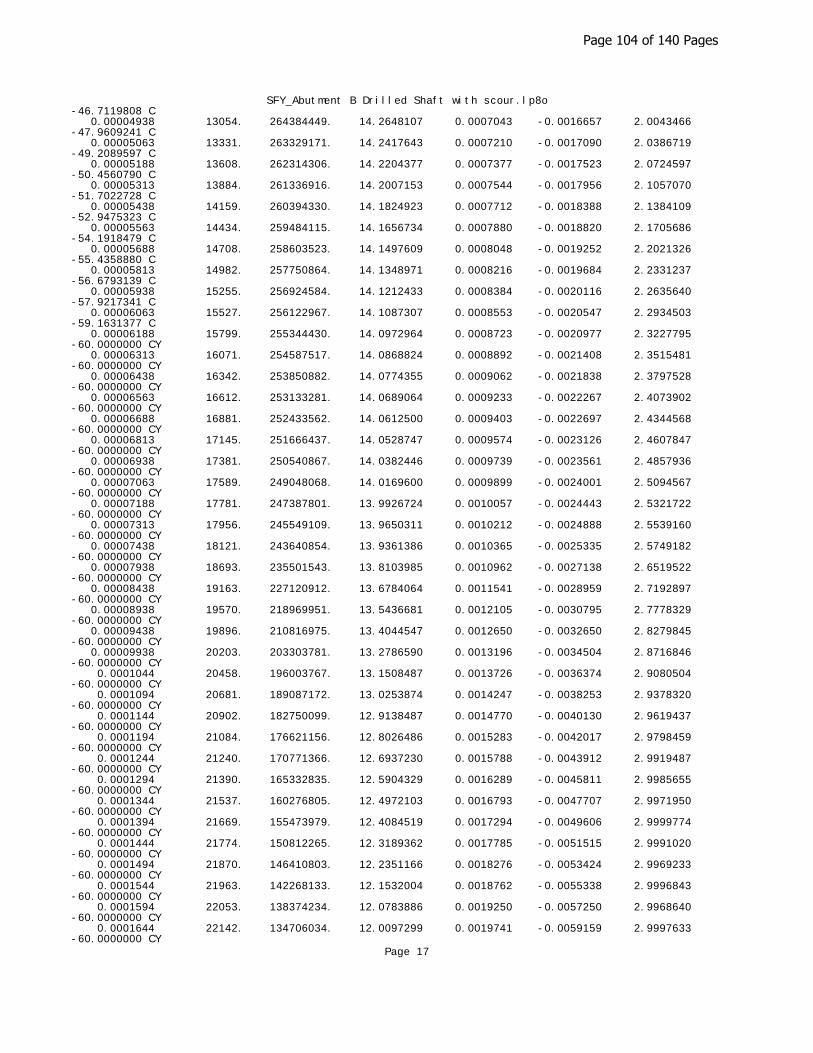
SFY_Abutment B Drilled Shaft with scour.lp8o-46.7119808 C 0.00004938 13054. 264384449. 14.2648107 0.0007043 -0.0016657 2.0043466 -47.9609241 C 0.00005063 13331. 263329171. 14.2417643 0.0007210 -0.0017090 2.0386719 -49.2089597 C 0.00005188 13608. 262314306. 14.2204377 0.0007377 -0.0017523 2.0724597 -50.4560790 C 0.00005313 13884. 261336916. 14.2007153 0.0007544 -0.0017956 2.1057070 -51.7022728 C 0.00005438 14159. 260394330. 14.1824923 0.0007712 -0.0018388 2.1384109 -52.9475323 C 0.00005563 14434. 259484115. 14.1656734 0.0007880 -0.0018820 2.1705686 -54.1918479 C 0.00005688 14708. 258603523. 14.1497609 0.0008048 -0.0019252 2.2021326 -55.4358880 C 0.00005813 14982. 257750864. 14.1348971 0.0008216 -0.0019684 2.2331237 -56.6793139 C 0.00005938 15255. 256924584. 14.1212433 0.0008384 -0.0020116 2.2635640 -57.9217341 C 0.00006063 15527. 256122967. 14.1087307 0.0008553 -0.0020547 2.2934503 -59.1631377 C 0.00006188 15799. 255344430. 14.0972964 0.0008723 -0.0020977 2.3227795 -60.0000000 CY 0.00006313 16071. 254587517. 14.0868824 0.0008892 -0.0021408 2.3515481 -60.0000000 CY 0.00006438 16342. 253850882. 14.0774355 0.0009062 -0.0021838 2.3797528 -60.0000000 CY 0.00006563 16612. 253133281. 14.0689064 0.0009233 -0.0022267 2.4073902 -60.0000000 CY 0.00006688 16881. 252433562. 14.0612500 0.0009403 -0.0022697 2.4344568 -60.0000000 CY 0.00006813 17145. 251666437. 14.0528747 0.0009574 -0.0023126 2.4607847 -60.0000000 CY 0.00006938 17381. 250540867. 14.0382446 0.0009739 -0.0023561 2.4857936 -60.0000000 CY 0.00007063 17589. 249048068. 14.0169600 0.0009899 -0.0024001 2.5094567 -60.0000000 CY 0.00007188 17781. 247387801. 13.9926724 0.0010057 -0.0024443 2.5321722 -60.0000000 CY 0.00007313 17956. 245549109. 13.9650311 0.0010212 -0.0024888 2.5539160 -60.0000000 CY 0.00007438 18121. 243640854. 13.9361386 0.0010365 -0.0025335 2.5749182 -60.0000000 CY 0.00007938 18693. 235501543. 13.8103985 0.0010962 -0.0027138 2.6519522 -60.0000000 CY 0.00008438 19163. 227120912. 13.6784064 0.0011541 -0.0028959 2.7192897 -60.0000000 CY 0.00008938 19570. 218969951. 13.5436681 0.0012105 -0.0030795 2.7778329 -60.0000000 CY 0.00009438 19896. 210816975. 13.4044547 0.0012650 -0.0032650 2.8279845 -60.0000000 CY 0.00009938 20203. 203303781. 13.2786590 0.0013196 -0.0034504 2.8716846 -60.0000000 CY 0.0001044 20458. 196003767. 13.1508487 0.0013726 -0.0036374 2.9080504 -60.0000000 CY 0.0001094 20681. 189087172. 13.0253874 0.0014247 -0.0038253 2.9378320 -60.0000000 CY 0.0001144 20902. 182750099. 12.9138487 0.0014770 -0.0040130 2.9619437 -60.0000000 CY 0.0001194 21084. 176621156. 12.8026486 0.0015283 -0.0042017 2.9798459 -60.0000000 CY 0.0001244 21240. 170771366. 12.6937230 0.0015788 -0.0043912 2.9919487 -60.0000000 CY 0.0001294 21390. 165332835. 12.5904329 0.0016289 -0.0045811 2.9985655 -60.0000000 CY 0.0001344 21537. 160276805. 12.4972103 0.0016793 -0.0047707 2.9971950 -60.0000000 CY 0.0001394 21669. 155473979. 12.4084519 0.0017294 -0.0049606 2.9999774 -60.0000000 CY 0.0001444 21774. 150812265. 12.3189362 0.0017785 -0.0051515 2.9991020 -60.0000000 CY 0.0001494 21870. 146410803. 12.2351166 0.0018276 -0.0053424 2.9969233 -60.0000000 CY 0.0001544 21963. 142268133. 12.1532004 0.0018762 -0.0055338 2.9996843 -60.0000000 CY 0.0001594 22053. 138374234. 12.0783886 0.0019250 -0.0057250 2.9968640 -60.0000000 CY 0.0001644 22142. 134706034. 12.0097299 0.0019741 -0.0059159 2.9997633 -60.0000000 CY
Page 17
Page 104 of 140 Pages

SFY_Abutment B Drilled Shaft with scour.lp8o 0.0001694 22226. 131224710. 11.9454129 0.0020233 -0.0061067 2.9962890 -60.0000000 CY 0.0001744 22297. 127867123. 11.8810741 0.0020718 -0.0062982 2.9994486 -60.0000000 CY 0.0001794 22353. 124617799. 11.8159581 0.0021195 -0.0064905 2.9974287 60.0000000 CY 0.0001844 22408. 121533987. 11.7549480 0.0021673 -0.0066827 2.9980647 60.0000000 CY 0.0001894 22460. 118599687. 11.6934013 0.0022144 -0.0068756 2.9998882 60.0000000 CY 0.0001944 22511. 115811474. 11.6362637 0.0022618 -0.0070682 2.9954739 60.0000000 CY 0.0001994 22561. 113159700. 11.5829429 0.0023093 -0.0072607 2.9980207 60.0000000 CY 0.0002044 22611. 110635046. 11.5330251 0.0023571 -0.0074529 2.9998314 60.0000000 CY 0.0002094 22660. 108227256. 11.4865173 0.0024050 -0.0076450 2.9963274 60.0000000 CY 0.0002144 22708. 105926035. 11.4427028 0.0024530 -0.0078370 2.9965770 60.0000000 CY 0.0002194 22754. 103720373. 11.4006776 0.0025010 -0.0080290 2.9991446 60.0000000 CY 0.0002244 22792. 101579799. 11.3574847 0.0025483 -0.0082217 2.9999995 60.0000000 CY 0.0002294 22827. 99520053. 11.3159346 0.0025956 -0.0084144 2.9945612 60.0000000 CY 0.0002344 22856. 97520369. 11.2727412 0.0026420 -0.0086080 2.9959177 60.0000000 CY 0.0002394 22884. 95597573. 11.2280431 0.0026877 -0.0088023 2.9984278 60.0000000 CY 0.0002444 22910. 93750649. 11.1853206 0.0027334 -0.0089966 2.9997638 60.0000000 CY 0.0002494 22937. 91976512. 11.1448705 0.0027793 -0.0091907 2.9982254 60.0000000 CY 0.0002544 22963. 90270757. 11.1065979 0.0028252 -0.0093848 2.9934088 60.0000000 CY 0.0002594 22988. 88630176. 11.0701252 0.0028713 -0.0095787 2.9945705 60.0000000 CY 0.0002644 23013. 87047800. 11.0361982 0.0029177 -0.0097723 2.9973758 60.0000000 CY 0.0002694 23038. 85522610. 11.0041045 0.0029642 -0.0099658 2.9991818 60.0000000 CY 0.0002744 23062. 84052385. 10.9735125 0.0030109 -0.0101591 2.9999654 60.0000000 CYT 0.0003044 23186. 76174531. 10.8302573 0.0032965 -0.0113135 2.9996655 60.0000000 CYT 0.0003344 23246. 69520815. 10.7135422 0.0035823 -0.0124677 2.9962872 60.0000000 CYT 0.0003644 23273. 63870221. 10.6161547 0.0038683 -0.0136217 2.9899357 60.0000000 CYT
-------------------------------------------------------------------------------- Summary of Results for Nominal (Unfactored) Moment Capacity for Section 1--------------------------------------------------------------------------------
Moment values interpolated at maximum compressive strain = 0.003or maximum developed moment if pile fails at smaller strains.
Load Axial Thrust Nominal Mom. Cap. Max. Comp. No. kips in-kip Strain ---- ---------------- ------------------ ------------ 1 83.057 22136.231 0.00300000 2 109.425 22509.046 0.00300000 3 116.465 22608.300 0.00300000 4 148.556 23056.233 0.00300000
Note that the values of moment capacity in the table above are not factored by a strength reduction factor (phi-factor).
In ACI 318, the value of the strength reduction factor depends on whether the transverse reinforcing steel bars are tied hoops (0.65) or spirals (0.70).
The above values should be multiplied by the appropriate strength reduction factor to compute ultimate moment capacity according to ACI 318, Section 9.3.2.2 or the value required by the design standard being followed.
The following table presents factored moment capacities and corresponding bending stiffnesses computed for common resistance factor values used for
Page 18
Page 105 of 140 Pages
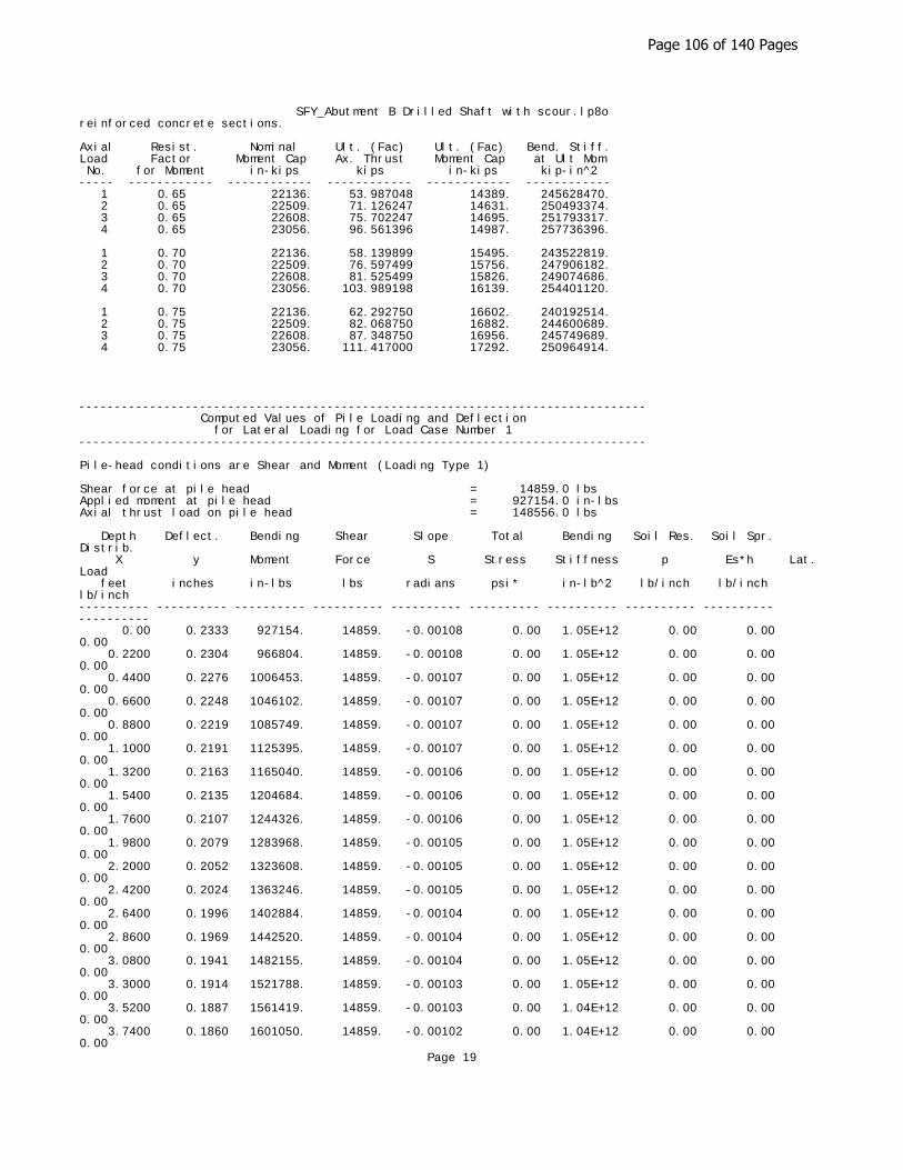
SFY_Abutment B Drilled Shaft with scour.lp8oreinforced concrete sections.
Axial Resist. Nominal Ult. (Fac) Ult. (Fac) Bend. Stiff.Load Factor Moment Cap Ax. Thrust Moment Cap at Ult Mom No. for Moment in-kips kips in-kips kip-in^2 ----- ------------ ------------ ------------ ------------ ------------ 1 0.65 22136. 53.987048 14389. 245628470. 2 0.65 22509. 71.126247 14631. 250493374. 3 0.65 22608. 75.702247 14695. 251793317. 4 0.65 23056. 96.561396 14987. 257736396. 1 0.70 22136. 58.139899 15495. 243522819. 2 0.70 22509. 76.597499 15756. 247906182. 3 0.70 22608. 81.525499 15826. 249074686. 4 0.70 23056. 103.989198 16139. 254401120. 1 0.75 22136. 62.292750 16602. 240192514. 2 0.75 22509. 82.068750 16882. 244600689. 3 0.75 22608. 87.348750 16956. 245749689. 4 0.75 23056. 111.417000 17292. 250964914.
-------------------------------------------------------------------------------- Computed Values of Pile Loading and Deflection for Lateral Loading for Load Case Number 1--------------------------------------------------------------------------------
Pile-head conditions are Shear and Moment (Loading Type 1)
Shear force at pile head = 14859.0 lbsApplied moment at pile head = 927154.0 in-lbsAxial thrust load on pile head = 148556.0 lbs
Depth Deflect. Bending Shear Slope Total Bending Soil Res. Soil Spr. Distrib. X y Moment Force S Stress Stiffness p Es*h Lat. Load feet inches in-lbs lbs radians psi* in-lb^2 lb/inch lb/inch lb/inch ---------- ---------- ---------- ---------- ---------- ---------- ---------- ---------- ---------- ---------- 0.00 0.2333 927154. 14859. -0.00108 0.00 1.05E+12 0.00 0.00 0.00 0.2200 0.2304 966804. 14859. -0.00108 0.00 1.05E+12 0.00 0.00 0.00 0.4400 0.2276 1006453. 14859. -0.00107 0.00 1.05E+12 0.00 0.00 0.00 0.6600 0.2248 1046102. 14859. -0.00107 0.00 1.05E+12 0.00 0.00 0.00 0.8800 0.2219 1085749. 14859. -0.00107 0.00 1.05E+12 0.00 0.00 0.00 1.1000 0.2191 1125395. 14859. -0.00107 0.00 1.05E+12 0.00 0.00 0.00 1.3200 0.2163 1165040. 14859. -0.00106 0.00 1.05E+12 0.00 0.00 0.00 1.5400 0.2135 1204684. 14859. -0.00106 0.00 1.05E+12 0.00 0.00 0.00 1.7600 0.2107 1244326. 14859. -0.00106 0.00 1.05E+12 0.00 0.00 0.00 1.9800 0.2079 1283968. 14859. -0.00105 0.00 1.05E+12 0.00 0.00 0.00 2.2000 0.2052 1323608. 14859. -0.00105 0.00 1.05E+12 0.00 0.00 0.00 2.4200 0.2024 1363246. 14859. -0.00105 0.00 1.05E+12 0.00 0.00 0.00 2.6400 0.1996 1402884. 14859. -0.00104 0.00 1.05E+12 0.00 0.00 0.00 2.8600 0.1969 1442520. 14859. -0.00104 0.00 1.05E+12 0.00 0.00 0.00 3.0800 0.1941 1482155. 14859. -0.00104 0.00 1.05E+12 0.00 0.00 0.00 3.3000 0.1914 1521788. 14859. -0.00103 0.00 1.05E+12 0.00 0.00 0.00 3.5200 0.1887 1561419. 14859. -0.00103 0.00 1.04E+12 0.00 0.00 0.00 3.7400 0.1860 1601050. 14859. -0.00102 0.00 1.04E+12 0.00 0.00 0.00
Page 19
Page 106 of 140 Pages

SFY_Abutment B Drilled Shaft with scour.lp8o 3.9600 0.1833 1640678. 14859. -0.00102 0.00 1.04E+12 0.00 0.00 0.00 4.1800 0.1806 1680305. 14859. -0.00102 0.00 1.04E+12 0.00 0.00 0.00 4.4000 0.1779 1719930. 14859. -0.00101 0.00 1.04E+12 0.00 0.00 0.00 4.6200 0.1753 1759554. 14859. -0.00101 0.00 1.04E+12 0.00 0.00 0.00 4.8400 0.1726 1799176. 14859. -0.00100 0.00 1.04E+12 0.00 0.00 0.00 5.0600 0.1700 1838796. 14859. -9.98E-04 0.00 1.04E+12 0.00 0.00 0.00 5.2800 0.1673 1878414. 14859. -9.93E-04 0.00 1.04E+12 0.00 0.00 0.00 5.5000 0.1647 1918030. 14859. -9.88E-04 0.00 1.04E+12 0.00 0.00 0.00 5.7200 0.1621 1957645. 14859. -9.83E-04 0.00 1.04E+12 0.00 0.00 0.00 5.9400 0.1595 1997257. 14859. -9.78E-04 0.00 1.04E+12 0.00 0.00 0.00 6.1600 0.1570 2036867. 14859. -9.73E-04 0.00 1.04E+12 0.00 0.00 0.00 6.3800 0.1544 2076476. 14859. -9.68E-04 0.00 1.04E+12 0.00 0.00 0.00 6.6000 0.1518 2116082. 14859. -9.63E-04 0.00 1.04E+12 0.00 0.00 0.00 6.8200 0.1493 2155687. 14859. -9.57E-04 0.00 1.04E+12 0.00 0.00 0.00 7.0400 0.1468 2195289. 14859. -9.52E-04 0.00 1.04E+12 0.00 0.00 0.00 7.2600 0.1443 2234889. 14859. -9.46E-04 0.00 1.04E+12 0.00 0.00 0.00 7.4800 0.1418 2274487. 14859. -9.41E-04 0.00 1.04E+12 0.00 0.00 0.00 7.7000 0.1393 2314082. 14859. -9.35E-04 0.00 1.04E+12 0.00 0.00 0.00 7.9200 0.1369 2353675. 14859. -9.29E-04 0.00 1.04E+12 0.00 0.00 0.00 8.1400 0.1344 2393266. 14859. -9.23E-04 0.00 1.04E+12 0.00 0.00 0.00 8.3600 0.1320 2432855. 14859. -9.17E-04 0.00 1.04E+12 0.00 0.00 0.00 8.5800 0.1296 2472441. 14859. -9.11E-04 0.00 1.04E+12 0.00 0.00 0.00 8.8000 0.1272 2512025. 14859. -9.04E-04 0.00 1.04E+12 0.00 0.00 0.00 9.0200 0.1248 2551606. 14859. -8.98E-04 0.00 1.04E+12 0.00 0.00 0.00 9.2400 0.1224 2591184. 14859. -8.91E-04 0.00 1.04E+12 0.00 0.00 0.00 9.4600 0.1201 2630760. 14859. -8.85E-04 0.00 1.04E+12 0.00 0.00 0.00 9.6800 0.1178 2670334. 14859. -8.78E-04 0.00 1.04E+12 0.00 0.00 0.00 9.9000 0.1155 2709905. 14859. -8.71E-04 0.00 1.04E+12 0.00 0.00 0.00 10.1200 0.1132 2749473. 14859. -8.64E-04 0.00 1.04E+12 0.00 0.00 0.00 10.3400 0.1109 2789038. 14859. -8.57E-04 0.00 1.04E+12 0.00 0.00 0.00 10.5600 0.1086 2828601. 14859. -8.50E-04 0.00 1.04E+12 0.00 0.00 0.00 10.7800 0.1064 2868160. 14859. -8.43E-04 0.00 1.04E+12 0.00 0.00 0.00 11.0000 0.1042 2907717. 14859. -8.36E-04 0.00 1.04E+12 0.00 0.00 0.00 11.2200 0.1020 2947271. 14859. -8.28E-04 0.00 1.04E+12 0.00 0.00 0.00 11.4400 0.09981 2986822. 14859. -8.21E-04 0.00 1.04E+12 0.00 0.00 0.00 11.6600 0.09765 3026371. 14859. -8.13E-04 0.00 1.04E+12 0.00 0.00 0.00 11.8800 0.09552 3065916. 14845. -8.05E-04 0.00 1.04E+12 -10.4451 288.6911 0.00 12.1000 0.09340 3105385. 14795. -7.97E-04 0.00 1.04E+12 -27.2537 770.3244 0.00 12.3200 0.09131 3144661. 14701. -7.90E-04 0.00 1.04E+12 -44.4499 1285. 0.00 12.5400 0.08923 3183625. 14560. -7.82E-04 0.00 1.04E+12 -61.9268 1832.
Page 20
Page 107 of 140 Pages

SFY_Abutment B Drilled Shaft with scour.lp8o0.00 12.7600 0.08718 3222153. 14374. -7.73E-04 0.00 1.04E+12 -79.5791 2410. 0.00 12.9800 0.08515 3260124. 14143. -7.65E-04 0.00 1.04E+12 -95.0270 2946. 0.00 13.2000 0.08314 3297429. 13873. -7.57E-04 0.00 1.04E+12 -109.2467 3469. 0.00 13.4200 0.08115 3333969. 13567. -7.48E-04 0.00 1.04E+12 -122.7041 3992. 0.00 13.6400 0.07919 3369651. 13227. -7.40E-04 0.00 1.04E+12 -135.4129 4514. 0.00 13.8600 0.07725 3404386. 12853. -7.31E-04 0.00 1.04E+12 -147.3868 5037. 0.00 14.0800 0.07533 3438090. 12449. -7.23E-04 0.00 1.04E+12 -158.6398 5560. 0.00 14.3000 0.07343 3470685. 12017. -7.14E-04 0.00 1.04E+12 -169.1858 6083. 0.00 14.5200 0.07156 3502098. 11557. -7.05E-04 0.00 1.04E+12 -179.0391 6605. 0.00 14.7400 0.06971 3532259. 11072. -6.96E-04 0.00 1.04E+12 -188.2142 7128. 0.00 14.9600 0.06788 3561105. 10564. -6.87E-04 0.00 1.04E+12 -196.7256 7651. 0.00 15.1800 0.06608 3588576. 10034. -6.78E-04 0.00 1.04E+12 -204.5880 8173. 0.00 15.4000 0.06430 3614618. 9485. -6.69E-04 0.00 1.04E+12 -211.8161 8696. 0.00 15.6200 0.06255 3639180. 8917. -6.60E-04 0.00 1.04E+12 -218.4249 9219. 0.00 15.8400 0.06082 3662216. 8332. -6.50E-04 0.00 1.04E+12 -224.4295 9742. 0.00 16.0600 0.05912 3683684. 7733. -6.41E-04 0.00 1.04E+12 -229.8449 10264. 0.00 16.2800 0.05744 3703546. 7119. -6.32E-04 0.00 1.04E+12 -234.6864 10787. 0.00 16.5000 0.05578 3721769. 6494. -6.22E-04 0.00 1.04E+12 -238.9691 11310. 0.00 16.7200 0.05415 3738323. 5858. -6.13E-04 0.00 1.04E+12 -242.7085 11832. 0.00 16.9400 0.05255 3753182. 5213. -6.03E-04 0.00 1.04E+12 -245.9198 12355. 0.00 17.1600 0.05097 3766323. 4561. -5.94E-04 0.00 1.04E+12 -248.6186 12878. 0.00 17.3800 0.04941 3777727. 3901. -5.84E-04 0.00 1.04E+12 -250.8202 13401. 0.00 17.6000 0.04788 3787379. 3237. -5.74E-04 0.00 1.04E+12 -252.5399 13923. 0.00 17.8200 0.04638 3795268. 2568. -5.65E-04 0.00 1.04E+12 -253.7934 14446. 0.00 18.0400 0.04490 3801384. 1897. -5.55E-04 0.00 1.04E+12 -254.5959 14969. 0.00 18.2600 0.04345 3805722. 1225. -5.45E-04 0.00 1.04E+12 -254.9629 15492. 0.00 18.4800 0.04202 3808279. 551.7585 -5.36E-04 0.00 1.04E+12 -254.9097 16014. 0.00 18.7000 0.04062 3809055. -120.5985 -5.26E-04 0.00 1.04E+12 -254.4516 16537. 0.00 18.9200 0.03925 3808054. -791.2315 -5.16E-04 0.00 1.04E+12 -253.6038 17060. 0.00 19.1400 0.03790 3805282. -1459. -5.07E-04 0.00 1.04E+12 -252.3814 17582. 0.00 19.3600 0.03657 3800748. -2123. -4.97E-04 0.00 1.04E+12 -250.7995 18105. 0.00 19.5800 0.03527 3794461. -2783. -4.87E-04 0.00 1.04E+12 -248.8731 18628. 0.00 19.8000 0.03400 3786436. -3437. -4.78E-04 0.00 1.04E+12 -246.6171 19151. 0.00 20.0200 0.03275 3776689. -4085. -4.68E-04 0.00 1.04E+12 -244.0461 19673. 0.00 20.2400 0.03153 3765237. -4725. -4.58E-04 0.00 1.04E+12 -241.1747 20196. 0.00 20.4600 0.03033 3752100. -5358. -4.49E-04 0.00 1.04E+12 -238.0174 20719. 0.00 20.6800 0.02916 3737300. -5981. -4.39E-04 0.00 1.04E+12 -234.5885 21241. 0.00 20.9000 0.02801 3720862. -6596. -4.30E-04 0.00 1.04E+12 -230.9021 21764. 0.00 21.1200 0.02689 3702811. -7200. -4.20E-04 0.00 1.04E+12 -226.9722 22287. 0.00
Page 21
Page 108 of 140 Pages
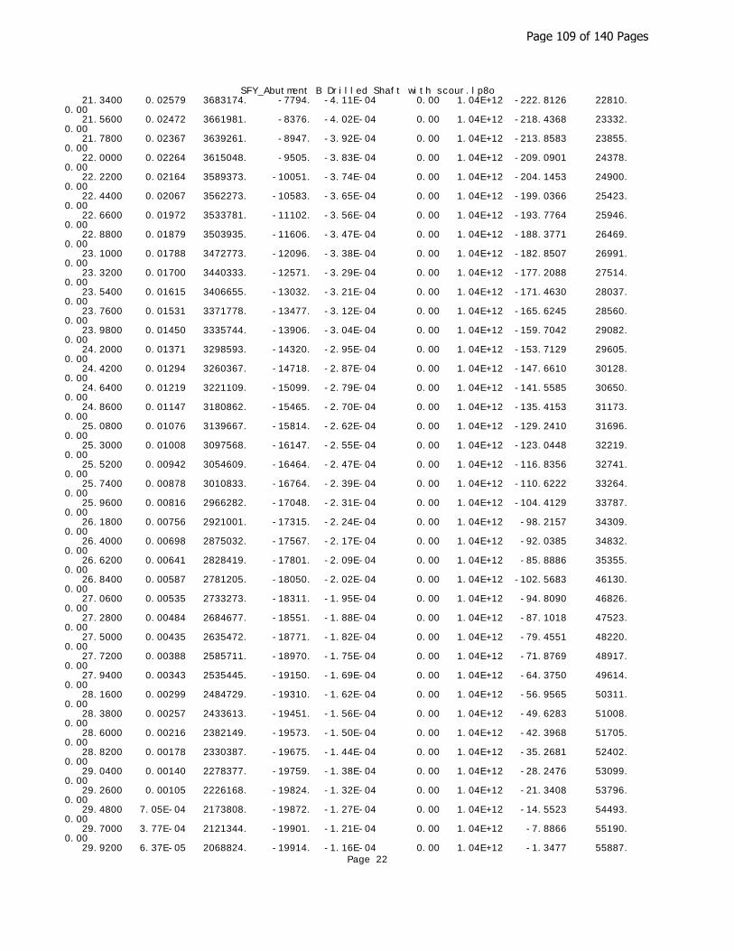
SFY_Abutment B Drilled Shaft with scour.lp8o 21.3400 0.02579 3683174. -7794. -4.11E-04 0.00 1.04E+12 -222.8126 22810. 0.00 21.5600 0.02472 3661981. -8376. -4.02E-04 0.00 1.04E+12 -218.4368 23332. 0.00 21.7800 0.02367 3639261. -8947. -3.92E-04 0.00 1.04E+12 -213.8583 23855. 0.00 22.0000 0.02264 3615048. -9505. -3.83E-04 0.00 1.04E+12 -209.0901 24378. 0.00 22.2200 0.02164 3589373. -10051. -3.74E-04 0.00 1.04E+12 -204.1453 24900. 0.00 22.4400 0.02067 3562273. -10583. -3.65E-04 0.00 1.04E+12 -199.0366 25423. 0.00 22.6600 0.01972 3533781. -11102. -3.56E-04 0.00 1.04E+12 -193.7764 25946. 0.00 22.8800 0.01879 3503935. -11606. -3.47E-04 0.00 1.04E+12 -188.3771 26469. 0.00 23.1000 0.01788 3472773. -12096. -3.38E-04 0.00 1.04E+12 -182.8507 26991. 0.00 23.3200 0.01700 3440333. -12571. -3.29E-04 0.00 1.04E+12 -177.2088 27514. 0.00 23.5400 0.01615 3406655. -13032. -3.21E-04 0.00 1.04E+12 -171.4630 28037. 0.00 23.7600 0.01531 3371778. -13477. -3.12E-04 0.00 1.04E+12 -165.6245 28560. 0.00 23.9800 0.01450 3335744. -13906. -3.04E-04 0.00 1.04E+12 -159.7042 29082. 0.00 24.2000 0.01371 3298593. -14320. -2.95E-04 0.00 1.04E+12 -153.7129 29605. 0.00 24.4200 0.01294 3260367. -14718. -2.87E-04 0.00 1.04E+12 -147.6610 30128. 0.00 24.6400 0.01219 3221109. -15099. -2.79E-04 0.00 1.04E+12 -141.5585 30650. 0.00 24.8600 0.01147 3180862. -15465. -2.70E-04 0.00 1.04E+12 -135.4153 31173. 0.00 25.0800 0.01076 3139667. -15814. -2.62E-04 0.00 1.04E+12 -129.2410 31696. 0.00 25.3000 0.01008 3097568. -16147. -2.55E-04 0.00 1.04E+12 -123.0448 32219. 0.00 25.5200 0.00942 3054609. -16464. -2.47E-04 0.00 1.04E+12 -116.8356 32741. 0.00 25.7400 0.00878 3010833. -16764. -2.39E-04 0.00 1.04E+12 -110.6222 33264. 0.00 25.9600 0.00816 2966282. -17048. -2.31E-04 0.00 1.04E+12 -104.4129 33787. 0.00 26.1800 0.00756 2921001. -17315. -2.24E-04 0.00 1.04E+12 -98.2157 34309. 0.00 26.4000 0.00698 2875032. -17567. -2.17E-04 0.00 1.04E+12 -92.0385 34832. 0.00 26.6200 0.00641 2828419. -17801. -2.09E-04 0.00 1.04E+12 -85.8886 35355. 0.00 26.8400 0.00587 2781205. -18050. -2.02E-04 0.00 1.04E+12 -102.5683 46130. 0.00 27.0600 0.00535 2733273. -18311. -1.95E-04 0.00 1.04E+12 -94.8090 46826. 0.00 27.2800 0.00484 2684677. -18551. -1.88E-04 0.00 1.04E+12 -87.1018 47523. 0.00 27.5000 0.00435 2635472. -18771. -1.82E-04 0.00 1.04E+12 -79.4551 48220. 0.00 27.7200 0.00388 2585711. -18970. -1.75E-04 0.00 1.04E+12 -71.8769 48917. 0.00 27.9400 0.00343 2535445. -19150. -1.69E-04 0.00 1.04E+12 -64.3750 49614. 0.00 28.1600 0.00299 2484729. -19310. -1.62E-04 0.00 1.04E+12 -56.9565 50311. 0.00 28.3800 0.00257 2433613. -19451. -1.56E-04 0.00 1.04E+12 -49.6283 51008. 0.00 28.6000 0.00216 2382149. -19573. -1.50E-04 0.00 1.04E+12 -42.3968 51705. 0.00 28.8200 0.00178 2330387. -19675. -1.44E-04 0.00 1.04E+12 -35.2681 52402. 0.00 29.0400 0.00140 2278377. -19759. -1.38E-04 0.00 1.04E+12 -28.2476 53099. 0.00 29.2600 0.00105 2226168. -19824. -1.32E-04 0.00 1.04E+12 -21.3408 53796. 0.00 29.4800 7.05E-04 2173808. -19872. -1.27E-04 0.00 1.04E+12 -14.5523 54493. 0.00 29.7000 3.77E-04 2121344. -19901. -1.21E-04 0.00 1.04E+12 -7.8866 55190. 0.00 29.9200 6.37E-05 2068824. -19914. -1.16E-04 0.00 1.04E+12 -1.3477 55887.
Page 22
Page 109 of 140 Pages
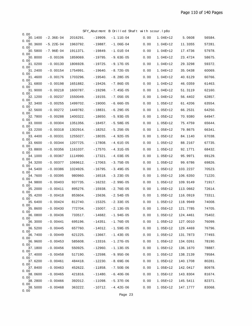
SFY_Abutment B Drilled Shaft with scour.lp8o0.00 30.1400 -2.36E-04 2016291. -19909. -1.11E-04 0.00 1.04E+12 5.0608 56584. 0.00 30.3600 -5.22E-04 1963792. -19887. -1.06E-04 0.00 1.04E+12 11.3355 57281. 0.00 30.5800 -7.96E-04 1911371. -19849. -1.01E-04 0.00 1.04E+12 17.4736 57978. 0.00 30.8000 -0.00106 1859069. -19795. -9.63E-05 0.00 1.04E+12 23.4724 58675. 0.00 31.0200 -0.00130 1806928. -19725. -9.17E-05 0.00 1.04E+12 29.3298 59372. 0.00 31.2400 -0.00154 1754991. -19640. -8.72E-05 0.00 1.04E+12 35.0438 60069. 0.00 31.4600 -0.00176 1703296. -19540. -8.28E-05 0.00 1.04E+12 40.6129 60766. 0.00 31.6800 -0.00198 1651882. -19426. -7.86E-05 0.00 1.04E+12 46.0359 61463. 0.00 31.9000 -0.00218 1600787. -19298. -7.45E-05 0.00 1.04E+12 51.3119 62160. 0.00 32.1200 -0.00237 1550049. -19155. -7.05E-05 0.00 1.04E+12 56.4402 62857. 0.00 32.3400 -0.00255 1499702. -19000. -6.66E-05 0.00 1.05E+12 61.4206 63554. 0.00 32.5600 -0.00272 1449782. -18831. -6.29E-05 0.00 1.05E+12 66.2531 64250. 0.00 32.7800 -0.00288 1400322. -18650. -5.93E-05 0.00 1.05E+12 70.9380 64947. 0.00 33.0000 -0.00304 1351356. -18457. -5.58E-05 0.00 1.05E+12 75.4759 65644. 0.00 33.2200 -0.00318 1302914. -18252. -5.25E-05 0.00 1.05E+12 79.8675 66341. 0.00 33.4400 -0.00331 1255027. -18035. -4.92E-05 0.00 1.05E+12 84.1140 67038. 0.00 33.6600 -0.00344 1207725. -17808. -4.61E-05 0.00 1.05E+12 88.2167 67735. 0.00 33.8800 -0.00356 1161037. -17570. -4.31E-05 0.00 1.05E+12 92.1771 68432. 0.00 34.1000 -0.00367 1114990. -17321. -4.03E-05 0.00 1.05E+12 95.9971 69129. 0.00 34.3200 -0.00377 1069612. -17063. -3.75E-05 0.00 1.05E+12 99.6786 69826. 0.00 34.5400 -0.00386 1024926. -16795. -3.49E-05 0.00 1.05E+12 103.2237 70523. 0.00 34.7600 -0.00395 980960. -16518. -3.23E-05 0.00 1.05E+12 106.6350 71220. 0.00 34.9800 -0.00403 937735. -16232. -2.99E-05 0.00 1.05E+12 109.9149 71917. 0.00 35.2000 -0.00411 895276. -15938. -2.76E-05 0.00 1.05E+12 113.0662 72614. 0.00 35.4200 -0.00418 853604. -15636. -2.54E-05 0.00 1.05E+12 116.0919 73311. 0.00 35.6400 -0.00424 812740. -15325. -2.33E-05 0.00 1.05E+12 118.9949 74008. 0.00 35.8600 -0.00430 772704. -15007. -2.13E-05 0.00 1.05E+12 121.7785 74705. 0.00 36.0800 -0.00436 733517. -14682. -1.94E-05 0.00 1.05E+12 124.4461 75402. 0.00 36.3000 -0.00441 695196. -14351. -1.76E-05 0.00 1.05E+12 127.0010 76099. 0.00 36.5200 -0.00445 657760. -14012. -1.59E-05 0.00 1.05E+12 129.4469 76796. 0.00 36.7400 -0.00449 621225. -13667. -1.43E-05 0.00 1.05E+12 131.7873 77493. 0.00 36.9600 -0.00453 585608. -13316. -1.27E-05 0.00 1.05E+12 134.0261 78190. 0.00 37.1800 -0.00456 550925. -12960. -1.13E-05 0.00 1.05E+12 136.1670 78887. 0.00 37.4000 -0.00458 517190. -12598. -9.95E-06 0.00 1.05E+12 138.2139 79584. 0.00 37.6200 -0.00461 484418. -12230. -8.69E-06 0.00 1.05E+12 140.1708 80281. 0.00 37.8400 -0.00463 452622. -11858. -7.50E-06 0.00 1.05E+12 142.0417 80978. 0.00 38.0600 -0.00465 421816. -11480. -6.40E-06 0.00 1.05E+12 143.8304 81674. 0.00 38.2800 -0.00466 392012. -11098. -5.37E-06 0.00 1.05E+12 145.5411 82371. 0.00 38.5000 -0.00468 363222. -10712. -4.42E-06 0.00 1.05E+12 147.1777 83068. 0.00
Page 23
Page 110 of 140 Pages
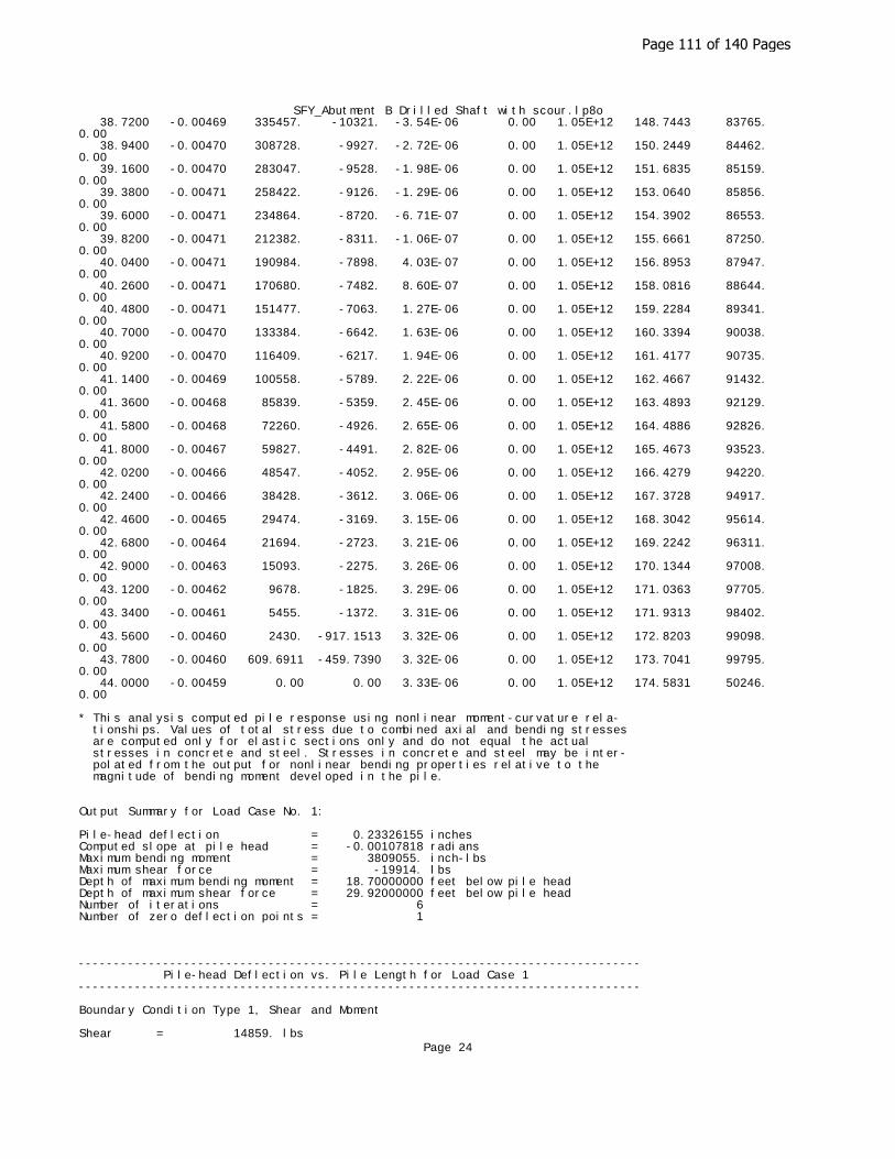
SFY_Abutment B Drilled Shaft with scour.lp8o 38.7200 -0.00469 335457. -10321. -3.54E-06 0.00 1.05E+12 148.7443 83765. 0.00 38.9400 -0.00470 308728. -9927. -2.72E-06 0.00 1.05E+12 150.2449 84462. 0.00 39.1600 -0.00470 283047. -9528. -1.98E-06 0.00 1.05E+12 151.6835 85159. 0.00 39.3800 -0.00471 258422. -9126. -1.29E-06 0.00 1.05E+12 153.0640 85856. 0.00 39.6000 -0.00471 234864. -8720. -6.71E-07 0.00 1.05E+12 154.3902 86553. 0.00 39.8200 -0.00471 212382. -8311. -1.06E-07 0.00 1.05E+12 155.6661 87250. 0.00 40.0400 -0.00471 190984. -7898. 4.03E-07 0.00 1.05E+12 156.8953 87947. 0.00 40.2600 -0.00471 170680. -7482. 8.60E-07 0.00 1.05E+12 158.0816 88644. 0.00 40.4800 -0.00471 151477. -7063. 1.27E-06 0.00 1.05E+12 159.2284 89341. 0.00 40.7000 -0.00470 133384. -6642. 1.63E-06 0.00 1.05E+12 160.3394 90038. 0.00 40.9200 -0.00470 116409. -6217. 1.94E-06 0.00 1.05E+12 161.4177 90735. 0.00 41.1400 -0.00469 100558. -5789. 2.22E-06 0.00 1.05E+12 162.4667 91432. 0.00 41.3600 -0.00468 85839. -5359. 2.45E-06 0.00 1.05E+12 163.4893 92129. 0.00 41.5800 -0.00468 72260. -4926. 2.65E-06 0.00 1.05E+12 164.4886 92826. 0.00 41.8000 -0.00467 59827. -4491. 2.82E-06 0.00 1.05E+12 165.4673 93523. 0.00 42.0200 -0.00466 48547. -4052. 2.95E-06 0.00 1.05E+12 166.4279 94220. 0.00 42.2400 -0.00466 38428. -3612. 3.06E-06 0.00 1.05E+12 167.3728 94917. 0.00 42.4600 -0.00465 29474. -3169. 3.15E-06 0.00 1.05E+12 168.3042 95614. 0.00 42.6800 -0.00464 21694. -2723. 3.21E-06 0.00 1.05E+12 169.2242 96311. 0.00 42.9000 -0.00463 15093. -2275. 3.26E-06 0.00 1.05E+12 170.1344 97008. 0.00 43.1200 -0.00462 9678. -1825. 3.29E-06 0.00 1.05E+12 171.0363 97705. 0.00 43.3400 -0.00461 5455. -1372. 3.31E-06 0.00 1.05E+12 171.9313 98402. 0.00 43.5600 -0.00460 2430. -917.1513 3.32E-06 0.00 1.05E+12 172.8203 99098. 0.00 43.7800 -0.00460 609.6911 -459.7390 3.32E-06 0.00 1.05E+12 173.7041 99795. 0.00 44.0000 -0.00459 0.00 0.00 3.33E-06 0.00 1.05E+12 174.5831 50246. 0.00
* This analysis computed pile response using nonlinear moment-curvature rela- tionships. Values of total stress due to combined axial and bending stresses are computed only for elastic sections only and do not equal the actual stresses in concrete and steel. Stresses in concrete and steel may be inter- polated from the output for nonlinear bending properties relative to the magnitude of bending moment developed in the pile.
Output Summary for Load Case No. 1:
Pile-head deflection = 0.23326155 inchesComputed slope at pile head = -0.00107818 radiansMaximum bending moment = 3809055. inch-lbsMaximum shear force = -19914. lbsDepth of maximum bending moment = 18.70000000 feet below pile headDepth of maximum shear force = 29.92000000 feet below pile headNumber of iterations = 6Number of zero deflection points = 1
-------------------------------------------------------------------------------- Pile-head Deflection vs. Pile Length for Load Case 1--------------------------------------------------------------------------------
Boundary Condition Type 1, Shear and Moment
Shear = 14859. lbsPage 24
Page 111 of 140 Pages

SFY_Abutment B Drilled Shaft with scour.lp8oMoment = 927154. in-lbsAxial Load = 148556. lbs
Pile Pile Head Maximum Maximum Length Deflection Moment Shear feet inches ln-lbs lbs ------------ ------------ ------------ ------------ 44.00000 0.23326155 3809055. -19914. 41.80000 0.23543823 3801051. -21088. 39.60000 0.24055239 3785328. -22826. 37.40000 0.25285480 3757585. -25103. 35.20000 0.28257330 3717401. -27685. 33.00000 0.34227666 3684560. -30846. 30.80000 0.47318667 3668116. -35385. 28.60000 0.84304825 3661269. -42861. 26.40000 2.34696066 3752402. -54877.
-------------------------------------------------------------------------------- Computed Values of Pile Loading and Deflection for Lateral Loading for Load Case Number 2--------------------------------------------------------------------------------
Pile-head conditions are Shear and Moment (Loading Type 1)
Shear force at pile head = 20580.0 lbsApplied moment at pile head = 1147303.0 in-lbsAxial thrust load on pile head = 83057.0 lbs
Depth Deflect. Bending Shear Slope Total Bending Soil Res. Soil Spr. Distrib. X y Moment Force S Stress Stiffness p Es*h Lat. Load feet inches in-lbs lbs radians psi* in-lb^2 lb/inch lb/inch lb/inch ---------- ---------- ---------- ---------- ---------- ---------- ---------- ---------- ---------- ---------- 0.00 0.3181 1147303. 20580. -0.00146 0.00 1.05E+12 0.00 0.00 0.00 0.2200 0.3142 1201953. 20580. -0.00145 0.00 1.05E+12 0.00 0.00 0.00 0.4400 0.3104 1256603. 20580. -0.00145 0.00 1.05E+12 0.00 0.00 0.00 0.6600 0.3066 1311252. 20580. -0.00145 0.00 1.05E+12 0.00 0.00 0.00 0.8800 0.3027 1365900. 20580. -0.00144 0.00 1.05E+12 0.00 0.00 0.00 1.1000 0.2989 1420548. 20580. -0.00144 0.00 1.05E+12 0.00 0.00 0.00 1.3200 0.2951 1475194. 20580. -0.00144 0.00 1.05E+12 0.00 0.00 0.00 1.5400 0.2913 1529840. 20580. -0.00143 0.00 1.05E+12 0.00 0.00 0.00 1.7600 0.2876 1584485. 20580. -0.00143 0.00 1.05E+12 0.00 0.00 0.00 1.9800 0.2838 1639129. 20580. -0.00143 0.00 1.05E+12 0.00 0.00 0.00 2.2000 0.2800 1693772. 20580. -0.00142 0.00 1.05E+12 0.00 0.00 0.00 2.4200 0.2763 1748415. 20580. -0.00142 0.00 1.05E+12 0.00 0.00 0.00 2.6400 0.2726 1803056. 20580. -0.00141 0.00 1.05E+12 0.00 0.00 0.00 2.8600 0.2688 1857696. 20580. -0.00141 0.00 1.05E+12 0.00 0.00 0.00 3.0800 0.2651 1912336. 20580. -0.00140 0.00 1.05E+12 0.00 0.00 0.00 3.3000 0.2614 1966974. 20580. -0.00140 0.00 1.05E+12 0.00 0.00 0.00 3.5200 0.2577 2021611. 20580. -0.00139 0.00 1.05E+12 0.00 0.00 0.00 3.7400 0.2541 2076247. 20580. -0.00139 0.00 1.05E+12 0.00 0.00 0.00 3.9600 0.2504 2130882. 20580. -0.00138 0.00 1.05E+12 0.00 0.00 0.00 4.1800 0.2468 2185516. 20580. -0.00138 0.00 1.05E+12 0.00 0.00 0.00 4.4000 0.2432 2240148. 20580. -0.00137 0.00 1.05E+12 0.00 0.00
Page 25
Page 112 of 140 Pages

SFY_Abutment B Drilled Shaft with scour.lp8o0.00 4.6200 0.2395 2294780. 20580. -0.00137 0.00 1.05E+12 0.00 0.00 0.00 4.8400 0.2359 2349410. 20580. -0.00136 0.00 1.05E+12 0.00 0.00 0.00 5.0600 0.2324 2404038. 20580. -0.00135 0.00 1.05E+12 0.00 0.00 0.00 5.2800 0.2288 2458666. 20580. -0.00135 0.00 1.05E+12 0.00 0.00 0.00 5.5000 0.2252 2513292. 20580. -0.00134 0.00 1.05E+12 0.00 0.00 0.00 5.7200 0.2217 2567916. 20580. -0.00133 0.00 1.05E+12 0.00 0.00 0.00 5.9400 0.2182 2622540. 20580. -0.00133 0.00 1.04E+12 0.00 0.00 0.00 6.1600 0.2147 2677161. 20580. -0.00132 0.00 1.04E+12 0.00 0.00 0.00 6.3800 0.2112 2731782. 20580. -0.00131 0.00 1.04E+12 0.00 0.00 0.00 6.6000 0.2078 2786400. 20580. -0.00131 0.00 1.04E+12 0.00 0.00 0.00 6.8200 0.2043 2841018. 20580. -0.00130 0.00 1.04E+12 0.00 0.00 0.00 7.0400 0.2009 2895633. 20580. -0.00129 0.00 1.04E+12 0.00 0.00 0.00 7.2600 0.1975 2950247. 20580. -0.00129 0.00 1.04E+12 0.00 0.00 0.00 7.4800 0.1941 3004860. 20580. -0.00128 0.00 1.04E+12 0.00 0.00 0.00 7.7000 0.1907 3059470. 20580. -0.00127 0.00 1.04E+12 0.00 0.00 0.00 7.9200 0.1874 3114079. 20580. -0.00126 0.00 1.04E+12 0.00 0.00 0.00 8.1400 0.1841 3168687. 20580. -0.00126 0.00 1.04E+12 0.00 0.00 0.00 8.3600 0.1808 3223292. 20580. -0.00125 0.00 1.04E+12 0.00 0.00 0.00 8.5800 0.1775 3277896. 20580. -0.00124 0.00 1.04E+12 0.00 0.00 0.00 8.8000 0.1742 3332498. 20580. -0.00123 0.00 1.04E+12 0.00 0.00 0.00 9.0200 0.1710 3387098. 20580. -0.00122 0.00 1.04E+12 0.00 0.00 0.00 9.2400 0.1678 3441696. 20580. -0.00121 0.00 1.04E+12 0.00 0.00 0.00 9.4600 0.1646 3496292. 20580. -0.00120 0.00 1.04E+12 0.00 0.00 0.00 9.6800 0.1614 3550887. 20580. -0.00120 0.00 1.04E+12 0.00 0.00 0.00 9.9000 0.1583 3605479. 20580. -0.00119 0.00 1.04E+12 0.00 0.00 0.00 10.1200 0.1551 3660069. 20580. -0.00118 0.00 1.04E+12 0.00 0.00 0.00 10.3400 0.1520 3714658. 20580. -0.00117 0.00 1.04E+12 0.00 0.00 0.00 10.5600 0.1490 3769244. 20580. -0.00116 0.00 1.04E+12 0.00 0.00 0.00 10.7800 0.1459 3823828. 20580. -0.00115 0.00 1.04E+12 0.00 0.00 0.00 11.0000 0.1429 3878410. 20580. -0.00114 0.00 1.04E+12 0.00 0.00 0.00 11.2200 0.1399 3932990. 20580. -0.00113 0.00 1.04E+12 0.00 0.00 0.00 11.4400 0.1369 3987568. 20580. -0.00112 0.00 1.04E+12 0.00 0.00 0.00 11.6600 0.1340 4042143. 20580. -0.00111 0.00 1.04E+12 0.00 0.00 0.00 11.8800 0.1311 4096716. 20565. -0.00110 0.00 1.04E+12 -11.3397 228.3575 0.00 12.1000 0.1282 4151208. 20511. -0.00109 0.00 1.04E+12 -29.6128 609.7655 0.00 12.3200 0.1254 4205491. 20408. -0.00108 0.00 1.04E+12 -48.3397 1018. 0.00 12.5400 0.1225 4259435. 20255. -0.00107 0.00 1.04E+12 -67.4068 1452. 0.00 12.7600 0.1197 4312907. 20052. -0.00106 0.00 1.04E+12 -86.7023 1912. 0.00 12.9800 0.1169 4365772. 19797. -0.00104 0.00 1.04E+12 -106.1156 2395. 0.00
Page 26
Page 113 of 140 Pages

SFY_Abutment B Drilled Shaft with scour.lp8o 13.2000 0.1142 4417895. 19492. -0.00103 0.00 1.04E+12 -125.5380 2902. 0.00 13.4200 0.1115 4469141. 19135. -0.00102 0.00 1.04E+12 -144.8626 3430. 0.00 13.6400 0.1088 4519374. 18727. -0.00101 0.00 1.04E+12 -163.9842 3979. 0.00 13.8600 0.1062 4568462. 18268. -9.99E-04 0.00 1.04E+12 -183.3829 4561. 0.00 14.0800 0.1035 4616270. 17758. -9.87E-04 0.00 1.04E+12 -203.0864 5179. 0.00 14.3000 0.1009 4662659. 17196. -9.76E-04 0.00 1.04E+12 -222.5922 5822. 0.00 14.5200 0.09838 4707494. 16583. -9.64E-04 0.00 1.04E+12 -241.8220 6489. 0.00 14.7400 0.09585 4750642. 15923. -9.52E-04 0.00 1.04E+12 -258.8061 7128. 0.00 14.9600 0.09336 4791983. 15224. -9.39E-04 0.00 1.04E+12 -270.5515 7651. 0.00 15.1800 0.09089 4831435. 14495. -9.27E-04 0.00 1.04E+12 -281.4083 8173. 0.00 15.4000 0.08846 4868924. 13739. -9.15E-04 0.00 1.03E+12 -291.3966 8696. 0.00 15.6200 0.08606 4904379. 12958. -9.02E-04 0.00 1.03E+12 -300.5366 9219. 0.00 15.8400 0.08370 4937737. 12153. -8.90E-04 0.00 1.03E+12 -308.8487 9742. 0.00 16.0600 0.08137 4968939. 11328. -8.77E-04 0.00 1.03E+12 -316.3533 10264. 0.00 16.2800 0.07907 4997934. 10484. -8.64E-04 0.00 1.03E+12 -323.0712 10787. 0.00 16.5000 0.07680 5024674. 9623. -8.52E-04 0.00 1.03E+12 -329.0231 11310. 0.00 16.7200 0.07457 5049118. 8748. -8.39E-04 0.00 1.03E+12 -334.2297 11832. 0.00 16.9400 0.07237 5071230. 7860. -8.26E-04 0.00 1.03E+12 -338.7120 12355. 0.00 17.1600 0.07021 5090978. 6960. -8.13E-04 0.00 1.03E+12 -342.4910 12878. 0.00 17.3800 0.06808 5108337. 6052. -8.00E-04 0.00 1.03E+12 -345.5876 13401. 0.00 17.6000 0.06599 5123284. 5136. -7.87E-04 0.00 1.03E+12 -348.0229 13923. 0.00 17.8200 0.06393 5135803. 4215. -7.74E-04 0.00 1.03E+12 -349.8178 14446. 0.00 18.0400 0.06190 5145880. 3290. -7.61E-04 0.00 1.03E+12 -350.9934 14969. 0.00 18.2600 0.05991 5153509. 2363. -7.47E-04 0.00 1.03E+12 -351.5707 15492. 0.00 18.4800 0.05796 5158684. 1435. -7.34E-04 0.00 1.03E+12 -351.5705 16014. 0.00 18.7000 0.05604 5161406. 507.3328 -7.21E-04 0.00 1.03E+12 -351.0137 16537. 0.00 18.9200 0.05415 5161679. -417.9012 -7.08E-04 0.00 1.03E+12 -349.9212 17060. 0.00 19.1400 0.05230 5159510. -1340. -6.95E-04 0.00 1.03E+12 -348.3135 17582. 0.00 19.3600 0.05048 5154911. -2256. -6.81E-04 0.00 1.03E+12 -346.2114 18105. 0.00 19.5800 0.04870 5147896. -3167. -6.68E-04 0.00 1.03E+12 -343.6351 18628. 0.00 19.8000 0.04695 5138482. -4070. -6.55E-04 0.00 1.03E+12 -340.6050 19151. 0.00 20.0200 0.04524 5126693. -4965. -6.42E-04 0.00 1.03E+12 -337.1413 19673. 0.00 20.2400 0.04356 5112550. -5850. -6.29E-04 0.00 1.03E+12 -333.2639 20196. 0.00 20.4600 0.04192 5096082. -6724. -6.16E-04 0.00 1.03E+12 -328.9925 20719. 0.00 20.6800 0.04031 5077318. -7586. -6.03E-04 0.00 1.03E+12 -324.3467 21241. 0.00 20.9000 0.03874 5056291. -8436. -5.90E-04 0.00 1.03E+12 -319.3459 21764. 0.00 21.1200 0.03720 5033035. -9272. -5.77E-04 0.00 1.03E+12 -314.0092 22287. 0.00 21.3400 0.03569 5007588. -10094. -5.64E-04 0.00 1.03E+12 -308.3554 22810. 0.00 21.5600 0.03422 4979989. -10900. -5.52E-04 0.00 1.03E+12 -302.4032 23332. 0.00 21.7800 0.03278 4950279. -11690. -5.39E-04 0.00 1.03E+12 -296.1708 23855.
Page 27
Page 114 of 140 Pages

SFY_Abutment B Drilled Shaft with scour.lp8o0.00 22.0000 0.03137 4918503. -12463. -5.26E-04 0.00 1.03E+12 -289.6763 24378. 0.00 22.2200 0.03000 4884705. -13219. -5.14E-04 0.00 1.03E+12 -282.9374 24900. 0.00 22.4400 0.02866 4848932. -13957. -5.01E-04 0.00 1.04E+12 -275.9717 25423. 0.00 22.6600 0.02735 4811233. -14676. -4.89E-04 0.00 1.04E+12 -268.7962 25946. 0.00 22.8800 0.02607 4771658. -15376. -4.77E-04 0.00 1.04E+12 -261.4276 26469. 0.00 23.1000 0.02483 4730258. -16056. -4.65E-04 0.00 1.04E+12 -253.8826 26991. 0.00 23.3200 0.02362 4687086. -16716. -4.53E-04 0.00 1.04E+12 -246.1771 27514. 0.00 23.5400 0.02244 4642196. -17356. -4.41E-04 0.00 1.04E+12 -238.3270 28037. 0.00 23.7600 0.02129 4595642. -17974. -4.29E-04 0.00 1.04E+12 -230.3477 28560. 0.00 23.9800 0.02018 4547480. -18572. -4.17E-04 0.00 1.04E+12 -222.2540 29082. 0.00 24.2000 0.01909 4497767. -19148. -4.06E-04 0.00 1.04E+12 -214.0608 29605. 0.00 24.4200 0.01803 4446559. -19702. -3.95E-04 0.00 1.04E+12 -205.7823 30128. 0.00 24.6400 0.01701 4393914. -20234. -3.83E-04 0.00 1.04E+12 -197.4324 30650. 0.00 24.8600 0.01601 4339891. -20744. -3.72E-04 0.00 1.04E+12 -189.0246 31173. 0.00 25.0800 0.01504 4284549. -21232. -3.61E-04 0.00 1.04E+12 -180.5720 31696. 0.00 25.3000 0.01410 4227945. -21698. -3.50E-04 0.00 1.04E+12 -172.0872 32219. 0.00 25.5200 0.01319 4170139. -22141. -3.40E-04 0.00 1.04E+12 -163.5827 32741. 0.00 25.7400 0.01231 4111191. -22561. -3.29E-04 0.00 1.04E+12 -155.0703 33264. 0.00 25.9600 0.01145 4051160. -22959. -3.19E-04 0.00 1.04E+12 -146.5614 33787. 0.00 26.1800 0.01062 3990105. -23335. -3.09E-04 0.00 1.04E+12 -138.0672 34309. 0.00 26.4000 0.00982 3928086. -23688. -2.99E-04 0.00 1.04E+12 -129.5982 34832. 0.00 26.6200 0.00905 3865161. -24019. -2.89E-04 0.00 1.04E+12 -121.1647 35355. 0.00 26.8400 0.00830 3801390. -24371. -2.79E-04 0.00 1.04E+12 -145.0020 46130. 0.00 27.0600 0.00757 3736606. -24740. -2.69E-04 0.00 1.04E+12 -134.3586 46826. 0.00 27.2800 0.00688 3670884. -25080. -2.60E-04 0.00 1.04E+12 -123.7840 47523. 0.00 27.5000 0.00620 3604296. -25393. -2.51E-04 0.00 1.04E+12 -113.2898 48220. 0.00 27.7200 0.00555 3536917. -25679. -2.42E-04 0.00 1.04E+12 -102.8871 48917. 0.00 27.9400 0.00493 3468819. -25937. -2.33E-04 0.00 1.04E+12 -92.5864 49614. 0.00 28.1600 0.00432 3400074. -26168. -2.24E-04 0.00 1.04E+12 -82.3976 50311. 0.00 28.3800 0.00374 3330753. -26372. -2.16E-04 0.00 1.04E+12 -72.3302 51008. 0.00 28.6000 0.00319 3260926. -26550. -2.07E-04 0.00 1.04E+12 -62.3929 51705. 0.00 28.8200 0.00265 3190662. -26701. -1.99E-04 0.00 1.04E+12 -52.5940 52402. 0.00 29.0400 0.00213 3120029. -26828. -1.91E-04 0.00 1.04E+12 -42.9411 53099. 0.00 29.2600 0.00164 3049096. -26928. -1.83E-04 0.00 1.04E+12 -33.4414 53796. 0.00 29.4800 0.00117 2977928. -27004. -1.76E-04 0.00 1.04E+12 -24.1016 54493. 0.00 29.7000 7.14E-04 2906590. -27056. -1.68E-04 0.00 1.04E+12 -14.9277 55190. 0.00 29.9200 2.80E-04 2835147. -27083. -1.61E-04 0.00 1.04E+12 -5.9253 55887. 0.00 30.1400 -1.35E-04 2763661. -27087. -1.54E-04 0.00 1.04E+12 2.9006 56584. 0.00 30.3600 -5.32E-04 2692193. -27068. -1.47E-04 0.00 1.04E+12 11.5454 57281. 0.00
Page 28
Page 115 of 140 Pages
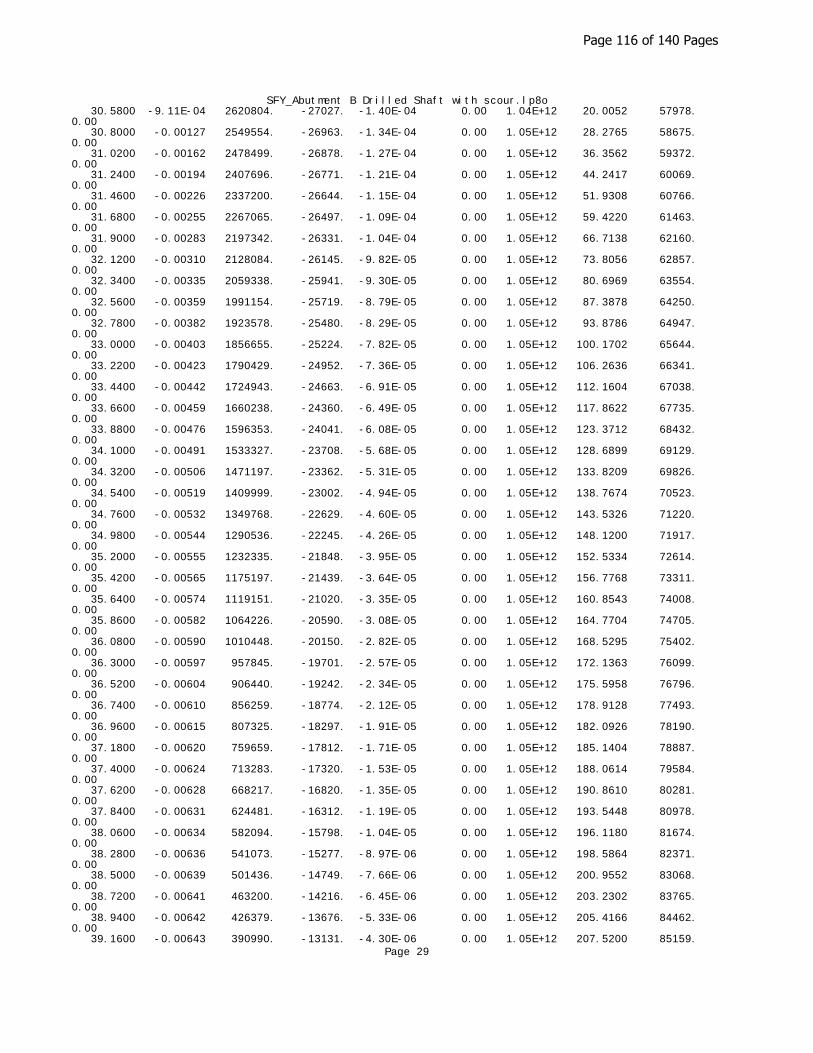
SFY_Abutment B Drilled Shaft with scour.lp8o 30.5800 -9.11E-04 2620804. -27027. -1.40E-04 0.00 1.04E+12 20.0052 57978. 0.00 30.8000 -0.00127 2549554. -26963. -1.34E-04 0.00 1.05E+12 28.2765 58675. 0.00 31.0200 -0.00162 2478499. -26878. -1.27E-04 0.00 1.05E+12 36.3562 59372. 0.00 31.2400 -0.00194 2407696. -26771. -1.21E-04 0.00 1.05E+12 44.2417 60069. 0.00 31.4600 -0.00226 2337200. -26644. -1.15E-04 0.00 1.05E+12 51.9308 60766. 0.00 31.6800 -0.00255 2267065. -26497. -1.09E-04 0.00 1.05E+12 59.4220 61463. 0.00 31.9000 -0.00283 2197342. -26331. -1.04E-04 0.00 1.05E+12 66.7138 62160. 0.00 32.1200 -0.00310 2128084. -26145. -9.82E-05 0.00 1.05E+12 73.8056 62857. 0.00 32.3400 -0.00335 2059338. -25941. -9.30E-05 0.00 1.05E+12 80.6969 63554. 0.00 32.5600 -0.00359 1991154. -25719. -8.79E-05 0.00 1.05E+12 87.3878 64250. 0.00 32.7800 -0.00382 1923578. -25480. -8.29E-05 0.00 1.05E+12 93.8786 64947. 0.00 33.0000 -0.00403 1856655. -25224. -7.82E-05 0.00 1.05E+12 100.1702 65644. 0.00 33.2200 -0.00423 1790429. -24952. -7.36E-05 0.00 1.05E+12 106.2636 66341. 0.00 33.4400 -0.00442 1724943. -24663. -6.91E-05 0.00 1.05E+12 112.1604 67038. 0.00 33.6600 -0.00459 1660238. -24360. -6.49E-05 0.00 1.05E+12 117.8622 67735. 0.00 33.8800 -0.00476 1596353. -24041. -6.08E-05 0.00 1.05E+12 123.3712 68432. 0.00 34.1000 -0.00491 1533327. -23708. -5.68E-05 0.00 1.05E+12 128.6899 69129. 0.00 34.3200 -0.00506 1471197. -23362. -5.31E-05 0.00 1.05E+12 133.8209 69826. 0.00 34.5400 -0.00519 1409999. -23002. -4.94E-05 0.00 1.05E+12 138.7674 70523. 0.00 34.7600 -0.00532 1349768. -22629. -4.60E-05 0.00 1.05E+12 143.5326 71220. 0.00 34.9800 -0.00544 1290536. -22245. -4.26E-05 0.00 1.05E+12 148.1200 71917. 0.00 35.2000 -0.00555 1232335. -21848. -3.95E-05 0.00 1.05E+12 152.5334 72614. 0.00 35.4200 -0.00565 1175197. -21439. -3.64E-05 0.00 1.05E+12 156.7768 73311. 0.00 35.6400 -0.00574 1119151. -21020. -3.35E-05 0.00 1.05E+12 160.8543 74008. 0.00 35.8600 -0.00582 1064226. -20590. -3.08E-05 0.00 1.05E+12 164.7704 74705. 0.00 36.0800 -0.00590 1010448. -20150. -2.82E-05 0.00 1.05E+12 168.5295 75402. 0.00 36.3000 -0.00597 957845. -19701. -2.57E-05 0.00 1.05E+12 172.1363 76099. 0.00 36.5200 -0.00604 906440. -19242. -2.34E-05 0.00 1.05E+12 175.5958 76796. 0.00 36.7400 -0.00610 856259. -18774. -2.12E-05 0.00 1.05E+12 178.9128 77493. 0.00 36.9600 -0.00615 807325. -18297. -1.91E-05 0.00 1.05E+12 182.0926 78190. 0.00 37.1800 -0.00620 759659. -17812. -1.71E-05 0.00 1.05E+12 185.1404 78887. 0.00 37.4000 -0.00624 713283. -17320. -1.53E-05 0.00 1.05E+12 188.0614 79584. 0.00 37.6200 -0.00628 668217. -16820. -1.35E-05 0.00 1.05E+12 190.8610 80281. 0.00 37.8400 -0.00631 624481. -16312. -1.19E-05 0.00 1.05E+12 193.5448 80978. 0.00 38.0600 -0.00634 582094. -15798. -1.04E-05 0.00 1.05E+12 196.1180 81674. 0.00 38.2800 -0.00636 541073. -15277. -8.97E-06 0.00 1.05E+12 198.5864 82371. 0.00 38.5000 -0.00639 501436. -14749. -7.66E-06 0.00 1.05E+12 200.9552 83068. 0.00 38.7200 -0.00641 463200. -14216. -6.45E-06 0.00 1.05E+12 203.2302 83765. 0.00 38.9400 -0.00642 426379. -13676. -5.33E-06 0.00 1.05E+12 205.4166 84462. 0.00 39.1600 -0.00643 390990. -13131. -4.30E-06 0.00 1.05E+12 207.5200 85159.
Page 29
Page 116 of 140 Pages
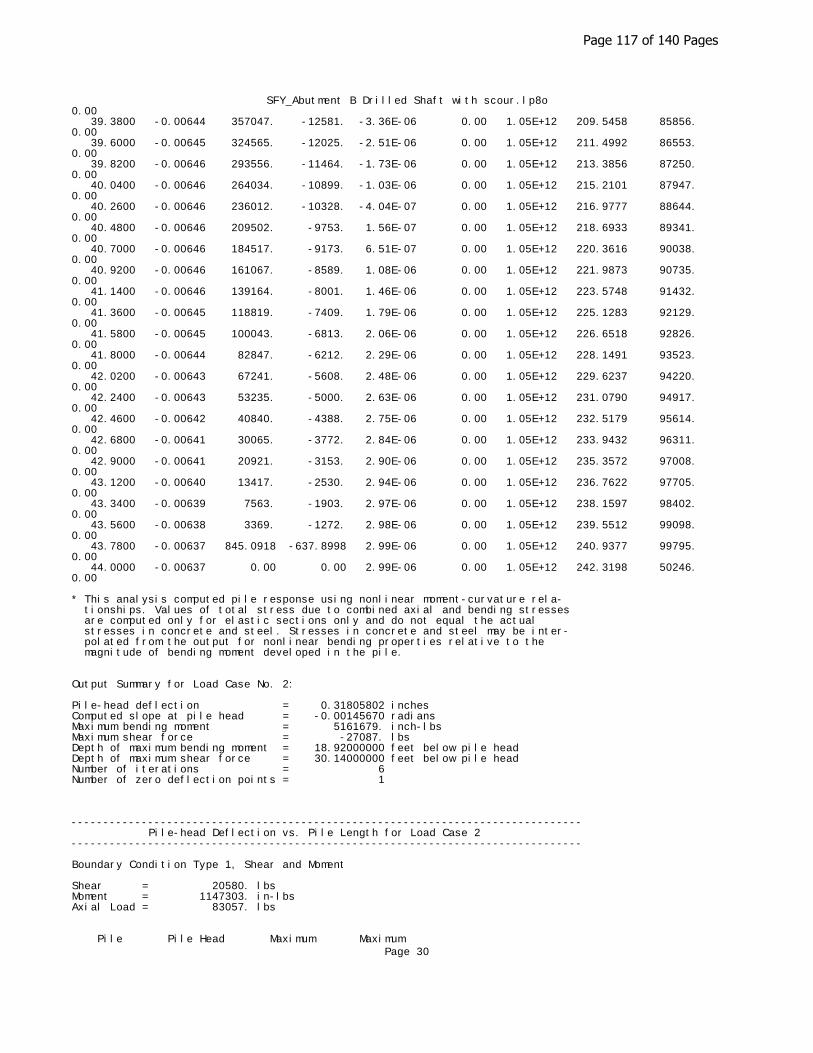
SFY_Abutment B Drilled Shaft with scour.lp8o0.00 39.3800 -0.00644 357047. -12581. -3.36E-06 0.00 1.05E+12 209.5458 85856. 0.00 39.6000 -0.00645 324565. -12025. -2.51E-06 0.00 1.05E+12 211.4992 86553. 0.00 39.8200 -0.00646 293556. -11464. -1.73E-06 0.00 1.05E+12 213.3856 87250. 0.00 40.0400 -0.00646 264034. -10899. -1.03E-06 0.00 1.05E+12 215.2101 87947. 0.00 40.2600 -0.00646 236012. -10328. -4.04E-07 0.00 1.05E+12 216.9777 88644. 0.00 40.4800 -0.00646 209502. -9753. 1.56E-07 0.00 1.05E+12 218.6933 89341. 0.00 40.7000 -0.00646 184517. -9173. 6.51E-07 0.00 1.05E+12 220.3616 90038. 0.00 40.9200 -0.00646 161067. -8589. 1.08E-06 0.00 1.05E+12 221.9873 90735. 0.00 41.1400 -0.00646 139164. -8001. 1.46E-06 0.00 1.05E+12 223.5748 91432. 0.00 41.3600 -0.00645 118819. -7409. 1.79E-06 0.00 1.05E+12 225.1283 92129. 0.00 41.5800 -0.00645 100043. -6813. 2.06E-06 0.00 1.05E+12 226.6518 92826. 0.00 41.8000 -0.00644 82847. -6212. 2.29E-06 0.00 1.05E+12 228.1491 93523. 0.00 42.0200 -0.00643 67241. -5608. 2.48E-06 0.00 1.05E+12 229.6237 94220. 0.00 42.2400 -0.00643 53235. -5000. 2.63E-06 0.00 1.05E+12 231.0790 94917. 0.00 42.4600 -0.00642 40840. -4388. 2.75E-06 0.00 1.05E+12 232.5179 95614. 0.00 42.6800 -0.00641 30065. -3772. 2.84E-06 0.00 1.05E+12 233.9432 96311. 0.00 42.9000 -0.00641 20921. -3153. 2.90E-06 0.00 1.05E+12 235.3572 97008. 0.00 43.1200 -0.00640 13417. -2530. 2.94E-06 0.00 1.05E+12 236.7622 97705. 0.00 43.3400 -0.00639 7563. -1903. 2.97E-06 0.00 1.05E+12 238.1597 98402. 0.00 43.5600 -0.00638 3369. -1272. 2.98E-06 0.00 1.05E+12 239.5512 99098. 0.00 43.7800 -0.00637 845.0918 -637.8998 2.99E-06 0.00 1.05E+12 240.9377 99795. 0.00 44.0000 -0.00637 0.00 0.00 2.99E-06 0.00 1.05E+12 242.3198 50246. 0.00
* This analysis computed pile response using nonlinear moment-curvature rela- tionships. Values of total stress due to combined axial and bending stresses are computed only for elastic sections only and do not equal the actual stresses in concrete and steel. Stresses in concrete and steel may be inter- polated from the output for nonlinear bending properties relative to the magnitude of bending moment developed in the pile.
Output Summary for Load Case No. 2:
Pile-head deflection = 0.31805802 inchesComputed slope at pile head = -0.00145670 radiansMaximum bending moment = 5161679. inch-lbsMaximum shear force = -27087. lbsDepth of maximum bending moment = 18.92000000 feet below pile headDepth of maximum shear force = 30.14000000 feet below pile headNumber of iterations = 6Number of zero deflection points = 1
-------------------------------------------------------------------------------- Pile-head Deflection vs. Pile Length for Load Case 2--------------------------------------------------------------------------------
Boundary Condition Type 1, Shear and Moment
Shear = 20580. lbsMoment = 1147303. in-lbsAxial Load = 83057. lbs
Pile Pile Head Maximum MaximumPage 30
Page 117 of 140 Pages

SFY_Abutment B Drilled Shaft with scour.lp8o Length Deflection Moment Shear feet inches ln-lbs lbs ------------ ------------ ------------ ------------ 44.00000 0.31805802 5161679. -27087. 41.80000 0.32131759 5152597. -28739. 39.60000 0.32902198 5135400. -31183. 37.40000 0.35301828 5102169. -34496. 35.20000 0.40643308 5068392. -38344. 33.00000 0.53058373 5032709. -43762. 30.80000 0.85049438 4985288. -51286. 28.60000 1.77241308 4952988. -61040. 26.40000 5.17530923 5036090. -74730.
-------------------------------------------------------------------------------- Computed Values of Pile Loading and Deflection for Lateral Loading for Load Case Number 3--------------------------------------------------------------------------------
Pile-head conditions are Shear and Moment (Loading Type 1)
Shear force at pile head = 20580.0 lbsApplied moment at pile head = 1192878.0 in-lbsAxial thrust load on pile head = 116465.0 lbs
Depth Deflect. Bending Shear Slope Total Bending Soil Res. Soil Spr. Distrib. X y Moment Force S Stress Stiffness p Es*h Lat. Load feet inches in-lbs lbs radians psi* in-lb^2 lb/inch lb/inch lb/inch ---------- ---------- ---------- ---------- ---------- ---------- ---------- ---------- ---------- ---------- 0.00 0.3708 1192878. 20580. -0.00170 0.00 1.05E+12 0.00 0.00 0.00 0.2200 0.3663 1247732. 20580. -0.00170 0.00 1.05E+12 0.00 0.00 0.00 0.4400 0.3618 1302585. 20580. -0.00170 0.00 1.05E+12 0.00 0.00 0.00 0.6600 0.3574 1357437. 20580. -0.00169 0.00 1.05E+12 0.00 0.00 0.00 0.8800 0.3529 1412288. 20580. -0.00169 0.00 1.05E+12 0.00 0.00 0.00 1.1000 0.3485 1467138. 20580. -0.00169 0.00 1.05E+12 0.00 0.00 0.00 1.3200 0.3440 1521987. 20580. -0.00168 0.00 1.05E+12 0.00 0.00 0.00 1.5400 0.3396 1576835. 20580. -0.00168 0.00 1.05E+12 0.00 0.00 0.00 1.7600 0.3352 1631681. 20580. -0.00167 0.00 1.05E+12 0.00 0.00 0.00 1.9800 0.3307 1686527. 20580. -0.00167 0.00 1.05E+12 0.00 0.00 0.00 2.2000 0.3263 1741371. 20580. -0.00167 0.00 1.05E+12 0.00 0.00 0.00 2.4200 0.3219 1796213. 20580. -0.00166 0.00 1.05E+12 0.00 0.00 0.00 2.6400 0.3176 1851054. 20580. -0.00166 0.00 1.05E+12 0.00 0.00 0.00 2.8600 0.3132 1905894. 20580. -0.00165 0.00 1.05E+12 0.00 0.00 0.00 3.0800 0.3088 1960732. 20580. -0.00165 0.00 1.05E+12 0.00 0.00 0.00 3.3000 0.3045 2015569. 20580. -0.00164 0.00 1.05E+12 0.00 0.00 0.00 3.5200 0.3002 2070404. 20580. -0.00164 0.00 1.05E+12 0.00 0.00 0.00 3.7400 0.2959 2125237. 20580. -0.00163 0.00 1.05E+12 0.00 0.00 0.00 3.9600 0.2916 2180069. 20580. -0.00163 0.00 1.05E+12 0.00 0.00 0.00 4.1800 0.2873 2234900. 20580. -0.00162 0.00 1.04E+12 0.00 0.00 0.00 4.4000 0.2830 2289728. 20580. -0.00161 0.00 1.04E+12 0.00 0.00 0.00 4.6200 0.2788 2344555. 20580. -0.00161 0.00 1.04E+12 0.00 0.00 0.00 4.8400 0.2745 2399379. 20580. -0.00160 0.00 1.04E+12 0.00 0.00 0.00
Page 31
Page 118 of 140 Pages
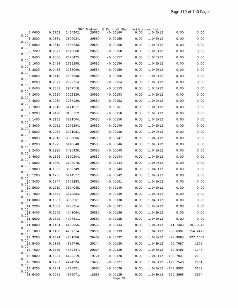
SFY_Abutment B Drilled Shaft with scour.lp8o 5.0600 0.2703 2454202. 20580. -0.00160 0.00 1.04E+12 0.00 0.00 0.00 5.2800 0.2661 2509024. 20580. -0.00159 0.00 1.04E+12 0.00 0.00 0.00 5.5000 0.2619 2563843. 20580. -0.00158 0.00 1.04E+12 0.00 0.00 0.00 5.7200 0.2577 2618660. 20580. -0.00158 0.00 1.04E+12 0.00 0.00 0.00 5.9400 0.2536 2673475. 20580. -0.00157 0.00 1.04E+12 0.00 0.00 0.00 6.1600 0.2494 2728288. 20580. -0.00156 0.00 1.04E+12 0.00 0.00 0.00 6.3800 0.2453 2783099. 20580. -0.00156 0.00 1.04E+12 0.00 0.00 0.00 6.6000 0.2412 2837908. 20580. -0.00155 0.00 1.04E+12 0.00 0.00 0.00 6.8200 0.2371 2892714. 20580. -0.00154 0.00 1.04E+12 0.00 0.00 0.00 7.0400 0.2331 2947518. 20580. -0.00153 0.00 1.04E+12 0.00 0.00 0.00 7.2600 0.2290 3002320. 20580. -0.00153 0.00 1.04E+12 0.00 0.00 0.00 7.4800 0.2250 3057120. 20580. -0.00152 0.00 1.04E+12 0.00 0.00 0.00 7.7000 0.2210 3111917. 20580. -0.00151 0.00 1.04E+12 0.00 0.00 0.00 7.9200 0.2170 3166712. 20580. -0.00150 0.00 1.04E+12 0.00 0.00 0.00 8.1400 0.2131 3221504. 20580. -0.00150 0.00 1.04E+12 0.00 0.00 0.00 8.3600 0.2091 3276294. 20580. -0.00149 0.00 1.04E+12 0.00 0.00 0.00 8.5800 0.2052 3331081. 20580. -0.00148 0.00 1.04E+12 0.00 0.00 0.00 8.8000 0.2013 3385866. 20580. -0.00147 0.00 1.04E+12 0.00 0.00 0.00 9.0200 0.1975 3440648. 20580. -0.00146 0.00 1.04E+12 0.00 0.00 0.00 9.2400 0.1936 3495428. 20580. -0.00145 0.00 1.04E+12 0.00 0.00 0.00 9.4600 0.1898 3550204. 20580. -0.00144 0.00 1.04E+12 0.00 0.00 0.00 9.6800 0.1860 3604978. 20580. -0.00144 0.00 1.04E+12 0.00 0.00 0.00 9.9000 0.1822 3659749. 20580. -0.00143 0.00 1.04E+12 0.00 0.00 0.00 10.1200 0.1785 3714517. 20580. -0.00142 0.00 1.04E+12 0.00 0.00 0.00 10.3400 0.1747 3769283. 20580. -0.00141 0.00 1.04E+12 0.00 0.00 0.00 10.5600 0.1710 3824045. 20580. -0.00140 0.00 1.04E+12 0.00 0.00 0.00 10.7800 0.1673 3878804. 20580. -0.00139 0.00 1.04E+12 0.00 0.00 0.00 11.0000 0.1637 3933561. 20580. -0.00138 0.00 1.04E+12 0.00 0.00 0.00 11.2200 0.1601 3988314. 20580. -0.00137 0.00 1.04E+12 0.00 0.00 0.00 11.4400 0.1565 4043064. 20580. -0.00136 0.00 1.04E+12 0.00 0.00 0.00 11.6600 0.1529 4097811. 20580. -0.00135 0.00 1.04E+12 0.00 0.00 0.00 11.8800 0.1494 4152555. 20565. -0.00134 0.00 1.04E+12 -11.7303 207.3345 0.00 12.1000 0.1458 4207214. 20509. -0.00133 0.00 1.04E+12 -30.6307 554.4479 0.00 12.3200 0.1424 4261656. 20402. -0.00132 0.00 1.04E+12 -49.9965 927.1509 0.00 12.5400 0.1389 4315746. 20244. -0.00130 0.00 1.04E+12 -69.7087 1325. 0.00 12.7600 0.1355 4369347. 20034. -0.00129 0.00 1.04E+12 -89.6496 1747. 0.00 12.9800 0.1321 4422319. 19771. -0.00128 0.00 1.04E+12 -109.7031 2193. 0.00 13.2000 0.1287 4474524. 19455. -0.00127 0.00 1.04E+12 -129.7543 2661. 0.00 13.4200 0.1254 4525821. 19086. -0.00126 0.00 1.04E+12 -149.6902 3152. 0.00 13.6400 0.1221 4576071. 18665. -0.00125 0.00 1.04E+12 -169.3995 3664.
Page 32
Page 119 of 140 Pages

SFY_Abutment B Drilled Shaft with scour.lp8o0.00 13.8600 0.1188 4625137. 18191. -0.00124 0.00 1.04E+12 -189.3480 4208. 0.00 14.0800 0.1155 4672879. 17664. -0.00122 0.00 1.04E+12 -209.5572 4789. 0.00 14.3000 0.1123 4719158. 17085. -0.00121 0.00 1.03E+12 -229.5245 5395. 0.00 14.5200 0.1091 4763832. 16453. -0.00120 0.00 1.03E+12 -249.1653 6027. 0.00 14.7400 0.1060 4806767. 15770. -0.00119 0.00 1.03E+12 -268.3966 6686. 0.00 14.9600 0.1029 4847827. 15036. -0.00118 0.00 1.03E+12 -287.1373 7369. 0.00 15.1800 0.09978 4886882. 14254. -0.00116 0.00 1.03E+12 -305.3079 8078. 0.00 15.4000 0.09672 4923806. 13431. -0.00115 0.00 1.03E+12 -318.6039 8696. 0.00 15.6200 0.09370 4958505. 12578. -0.00114 0.00 1.03E+12 -327.2073 9219. 0.00 15.8400 0.09071 4990919. 11705. -0.00113 0.00 1.03E+12 -334.7378 9742. 0.00 16.0600 0.08776 5020997. 10812. -0.00111 0.00 1.03E+12 -341.2164 10264. 0.00 16.2800 0.08484 5048693. 9904. -0.00110 0.00 1.03E+12 -346.6636 10787. 0.00 16.5000 0.08196 5073968. 8983. -0.00109 0.00 1.03E+12 -351.1006 11310. 0.00 16.7200 0.07910 5096793. 8052. -0.00107 0.00 1.03E+12 -354.5482 11832. 0.00 16.9400 0.07629 5117142. 7113. -0.00106 0.00 1.03E+12 -357.0276 12355. 0.00 17.1600 0.07351 5135000. 6168. -0.00105 0.00 1.03E+12 -358.5599 12878. 0.00 17.3800 0.07076 5150354. 5221. -0.00103 0.00 1.03E+12 -359.1661 13401. 0.00 17.6000 0.06804 5163200. 4273. -0.00102 0.00 9.29E+11 -358.8675 13923. 0.00 17.8200 0.06537 5173541. 3327. -9.99E-04 0.00 4.99E+11 -357.7064 14446. 0.00 18.0400 0.06277 5181381. 2385. -9.64E-04 0.00 3.17E+11 -355.8961 14969. 0.00 18.2600 0.06028 5186727. 1448. -9.21E-04 0.00 3.17E+11 -353.7228 15492. 0.00 18.4800 0.05791 5189594. 517.7128 -8.78E-04 0.00 3.17E+11 -351.2550 16014. 0.00 18.7000 0.05565 5190000. -406.0444 -8.35E-04 0.00 3.17E+11 -348.5611 16537. 0.00 18.9200 0.05350 5187964. -1322. -7.91E-04 0.00 3.17E+11 -345.7088 17060. 0.00 19.1400 0.05147 5183504. -2231. -7.48E-04 0.00 3.17E+11 -342.7653 17582. 0.00 19.3600 0.04955 5176643. -3132. -7.05E-04 0.00 3.18E+11 -339.7975 18105. 0.00 19.5800 0.04774 5167400. -4025. -6.70E-04 0.00 5.13E+11 -336.8714 18628. 0.00 19.8000 0.04601 5155801. -4911. -6.50E-04 0.00 9.51E+11 -333.7395 19151. 0.00 20.0200 0.04431 5141871. -5787. -6.36E-04 0.00 1.03E+12 -330.2022 19673. 0.00 20.2400 0.04265 5125636. -6654. -6.23E-04 0.00 1.03E+12 -326.2583 20196. 0.00 20.4600 0.04102 5107123. -7509. -6.10E-04 0.00 1.03E+12 -321.9274 20719. 0.00 20.6800 0.03943 5086363. -8353. -5.97E-04 0.00 1.03E+12 -317.2290 21241. 0.00 20.9000 0.03787 5063387. -9184. -5.84E-04 0.00 1.03E+12 -312.1825 21764. 0.00 21.1200 0.03634 5038232. -10001. -5.71E-04 0.00 1.03E+12 -306.8068 22287. 0.00 21.3400 0.03485 5010935. -10803. -5.58E-04 0.00 1.03E+12 -301.1207 22810. 0.00 21.5600 0.03339 4981534. -11590. -5.46E-04 0.00 1.03E+12 -295.1428 23332. 0.00 21.7800 0.03197 4950073. -12361. -5.33E-04 0.00 1.03E+12 -288.8913 23855. 0.00 22.0000 0.03058 4916595. -13115. -5.20E-04 0.00 1.03E+12 -282.3842 24378. 0.00 22.2200 0.02922 4881144. -13852. -5.08E-04 0.00 1.03E+12 -275.6391 24900. 0.00
Page 33
Page 120 of 140 Pages

SFY_Abutment B Drilled Shaft with scour.lp8o 22.4400 0.02790 4843769. -14570. -4.95E-04 0.00 1.03E+12 -268.6734 25423. 0.00 22.6600 0.02661 4804517. -15270. -4.83E-04 0.00 1.03E+12 -261.5040 25946. 0.00 22.8800 0.02535 4763439. -15951. -4.71E-04 0.00 1.03E+12 -254.1476 26469. 0.00 23.1000 0.02412 4720586. -16612. -4.59E-04 0.00 1.03E+12 -246.6206 26991. 0.00 23.3200 0.02293 4676011. -17253. -4.47E-04 0.00 1.04E+12 -238.9390 27514. 0.00 23.5400 0.02176 4629766. -17873. -4.35E-04 0.00 1.04E+12 -231.1184 28037. 0.00 23.7600 0.02063 4581907. -18473. -4.23E-04 0.00 1.04E+12 -223.1740 28560. 0.00 23.9800 0.01953 4532489. -19052. -4.12E-04 0.00 1.04E+12 -215.1208 29082. 0.00 24.2000 0.01846 4481568. -19609. -4.00E-04 0.00 1.04E+12 -206.9732 29605. 0.00 24.4200 0.01742 4429201. -20144. -3.89E-04 0.00 1.04E+12 -198.7454 30128. 0.00 24.6400 0.01640 4375445. -20658. -3.78E-04 0.00 1.04E+12 -190.4511 30650. 0.00 24.8600 0.01542 4320359. -21150. -3.66E-04 0.00 1.04E+12 -182.1037 31173. 0.00 25.0800 0.01447 4264000. -21619. -3.56E-04 0.00 1.04E+12 -173.7161 31696. 0.00 25.3000 0.01354 4206427. -22067. -3.45E-04 0.00 1.04E+12 -165.3010 32219. 0.00 25.5200 0.01265 4147699. -22492. -3.34E-04 0.00 1.04E+12 -156.8704 32741. 0.00 25.7400 0.01178 4087874. -22895. -3.24E-04 0.00 1.04E+12 -148.4360 33264. 0.00 25.9600 0.01094 4027011. -23276. -3.13E-04 0.00 1.04E+12 -140.0093 33787. 0.00 26.1800 0.01013 3965169. -23634. -3.03E-04 0.00 1.04E+12 -131.6010 34309. 0.00 26.4000 0.00934 3902407. -23971. -2.93E-04 0.00 1.04E+12 -123.2217 34832. 0.00 26.6200 0.00858 3838783. -24285. -2.83E-04 0.00 1.04E+12 -114.8814 35355. 0.00 26.8400 0.00784 3774356. -24618. -2.74E-04 0.00 1.04E+12 -137.0476 46130. 0.00 27.0600 0.00713 3708970. -24966. -2.64E-04 0.00 1.04E+12 -126.5285 46826. 0.00 27.2800 0.00645 3642700. -25286. -2.55E-04 0.00 1.04E+12 -116.0824 47523. 0.00 27.5000 0.00579 3575618. -25579. -2.46E-04 0.00 1.04E+12 -105.7207 48220. 0.00 27.7200 0.00515 3507796. -25844. -2.37E-04 0.00 1.04E+12 -95.4544 48917. 0.00 27.9400 0.00454 3439306. -26083. -2.28E-04 0.00 1.04E+12 -85.2937 49614. 0.00 28.1600 0.00395 3370219. -26295. -2.19E-04 0.00 1.04E+12 -75.2485 50311. 0.00 28.3800 0.00338 3300605. -26480. -2.11E-04 0.00 1.04E+12 -65.3277 51008. 0.00 28.6000 0.00284 3230533. -26640. -2.02E-04 0.00 1.04E+12 -55.5402 51705. 0.00 28.8200 0.00231 3160071. -26774. -1.94E-04 0.00 1.04E+12 -45.8939 52402. 0.00 29.0400 0.00181 3089287. -26882. -1.86E-04 0.00 1.04E+12 -36.3965 53099. 0.00 29.2600 0.00133 3018247. -26966. -1.79E-04 0.00 1.04E+12 -27.0548 53796. 0.00 29.4800 8.66E-04 2947016. -27025. -1.71E-04 0.00 1.04E+12 -17.8753 54493. 0.00 29.7000 4.24E-04 2875658. -27061. -1.64E-04 0.00 1.04E+12 -8.8640 55190. 0.00 29.9200 1.24E-06 2804236. -27072. -1.57E-04 0.00 1.04E+12 -0.02631 55887. 0.00 30.1400 -4.03E-04 2732812. -27061. -1.50E-04 0.00 1.04E+12 8.6330 56584. 0.00 30.3600 -7.89E-04 2661446. -27027. -1.43E-04 0.00 1.04E+12 17.1094 57281. 0.00 30.5800 -0.00116 2590197. -26971. -1.36E-04 0.00 1.04E+12 25.3992 57978. 0.00 30.8000 -0.00151 2519123. -26893. -1.30E-04 0.00 1.04E+12 33.4989 58675. 0.00 31.0200 -0.00184 2448281. -26794. -1.23E-04 0.00 1.04E+12 41.4056 59372.
Page 34
Page 121 of 140 Pages

SFY_Abutment B Drilled Shaft with scour.lp8o0.00 31.2400 -0.00216 2377725. -26675. -1.17E-04 0.00 1.04E+12 49.1167 60069. 0.00 31.4600 -0.00246 2307509. -26535. -1.11E-04 0.00 1.04E+12 56.6304 60766. 0.00 31.6800 -0.00275 2237687. -26376. -1.06E-04 0.00 1.04E+12 63.9449 61463. 0.00 31.9000 -0.00302 2168309. -26198. -1.00E-04 0.00 1.05E+12 71.0591 62160. 0.00 32.1200 -0.00327 2099424. -26001. -9.47E-05 0.00 1.05E+12 77.9724 62857. 0.00 32.3400 -0.00352 2031081. -25786. -8.94E-05 0.00 1.05E+12 84.6844 63554. 0.00 32.5600 -0.00375 1963326. -25554. -8.44E-05 0.00 1.05E+12 91.1951 64250. 0.00 32.7800 -0.00396 1896206. -25305. -7.95E-05 0.00 1.05E+12 97.5052 64947. 0.00 33.0000 -0.00417 1829763. -25040. -7.48E-05 0.00 1.05E+12 103.6154 65644. 0.00 33.2200 -0.00436 1764042. -24758. -7.03E-05 0.00 1.05E+12 109.5268 66341. 0.00 33.4400 -0.00454 1699082. -24462. -6.59E-05 0.00 1.05E+12 115.2409 67038. 0.00 33.6600 -0.00471 1634925. -24150. -6.17E-05 0.00 1.05E+12 120.7597 67735. 0.00 33.8800 -0.00486 1571607. -23824. -5.77E-05 0.00 1.05E+12 126.0851 68432. 0.00 34.1000 -0.00501 1509167. -23485. -5.38E-05 0.00 1.05E+12 131.2198 69129. 0.00 34.3200 -0.00515 1447641. -23132. -5.01E-05 0.00 1.05E+12 136.1664 69826. 0.00 34.5400 -0.00528 1387063. -22766. -4.65E-05 0.00 1.05E+12 140.9280 70523. 0.00 34.7600 -0.00539 1327465. -22388. -4.31E-05 0.00 1.05E+12 145.5079 71220. 0.00 34.9800 -0.00550 1268881. -21998. -3.98E-05 0.00 1.05E+12 149.9096 71917. 0.00 35.2000 -0.00560 1211341. -21597. -3.67E-05 0.00 1.05E+12 154.1368 72614. 0.00 35.4200 -0.00570 1154873. -21184. -3.37E-05 0.00 1.05E+12 158.1936 73311. 0.00 35.6400 -0.00578 1099508. -20762. -3.09E-05 0.00 1.05E+12 162.0840 74008. 0.00 35.8600 -0.00586 1045271. -20329. -2.82E-05 0.00 1.05E+12 165.8124 74705. 0.00 36.0800 -0.00593 992190. -19886. -2.56E-05 0.00 1.05E+12 169.3834 75402. 0.00 36.3000 -0.00599 940288. -19435. -2.32E-05 0.00 1.05E+12 172.8015 76099. 0.00 36.5200 -0.00605 889589. -18974. -2.09E-05 0.00 1.05E+12 176.0717 76796. 0.00 36.7400 -0.00610 840117. -18505. -1.87E-05 0.00 1.05E+12 179.1989 77493. 0.00 36.9600 -0.00615 791894. -18028. -1.66E-05 0.00 1.05E+12 182.1881 78190. 0.00 37.1800 -0.00619 744939. -17543. -1.47E-05 0.00 1.05E+12 185.0445 78887. 0.00 37.4000 -0.00623 699274. -17051. -1.29E-05 0.00 1.05E+12 187.7733 79584. 0.00 37.6200 -0.00626 654916. -16552. -1.12E-05 0.00 1.05E+12 190.3799 80281. 0.00 37.8400 -0.00629 611886. -16046. -9.57E-06 0.00 1.05E+12 192.8697 80978. 0.00 38.0600 -0.00631 570199. -15534. -8.08E-06 0.00 1.05E+12 195.2480 81674. 0.00 38.2800 -0.00633 529872. -15015. -6.69E-06 0.00 1.05E+12 197.5203 82371. 0.00 38.5000 -0.00635 490921. -14491. -5.41E-06 0.00 1.05E+12 199.6919 83068. 0.00 38.7200 -0.00636 453362. -13961. -4.22E-06 0.00 1.05E+12 201.7685 83765. 0.00 38.9400 -0.00637 417209. -13426. -3.12E-06 0.00 1.05E+12 203.7552 84462. 0.00 39.1600 -0.00638 382475. -12885. -2.11E-06 0.00 1.05E+12 205.6576 85159. 0.00 39.3800 -0.00638 349175. -12340. -1.19E-06 0.00 1.05E+12 207.4809 85856. 0.00 39.6000 -0.00638 317320. -11790. -3.53E-07 0.00 1.05E+12 209.2303 86553. 0.00
Page 35
Page 122 of 140 Pages
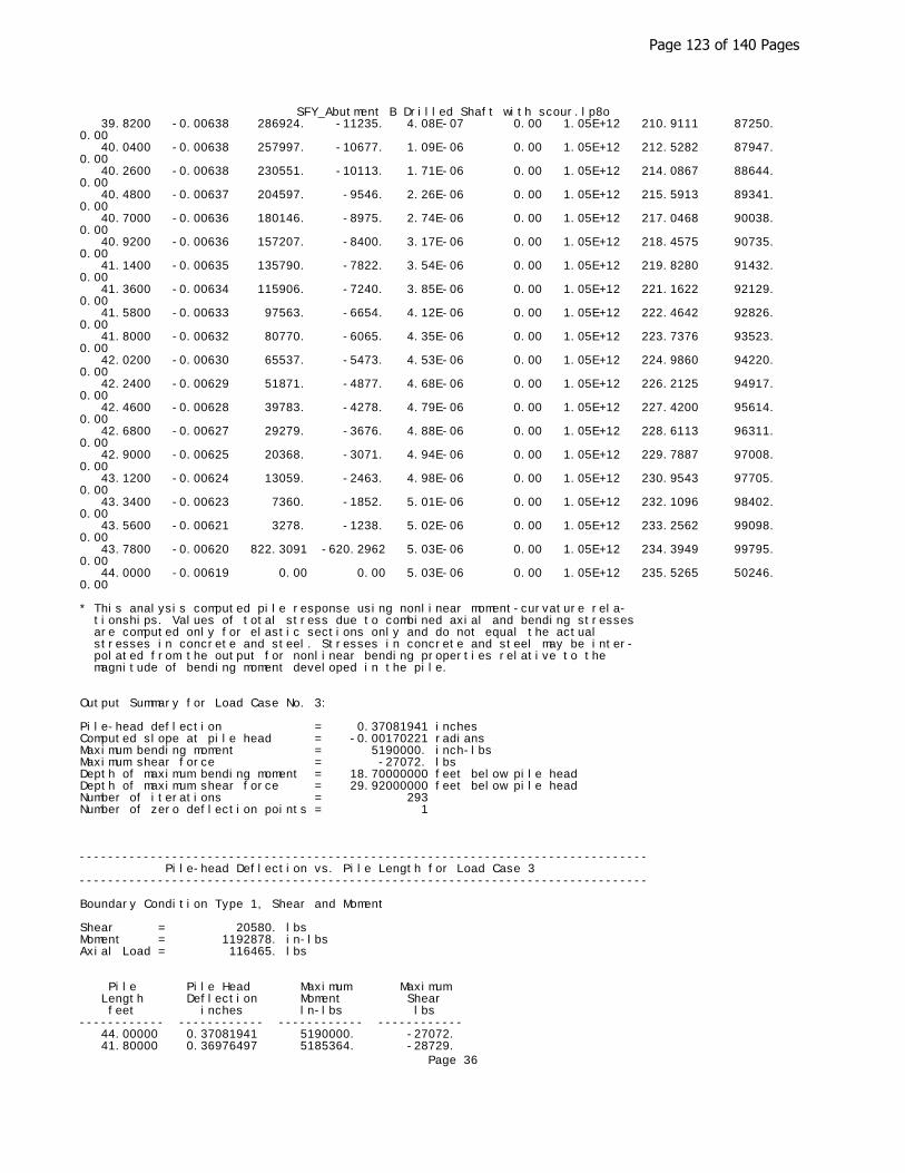
SFY_Abutment B Drilled Shaft with scour.lp8o 39.8200 -0.00638 286924. -11235. 4.08E-07 0.00 1.05E+12 210.9111 87250. 0.00 40.0400 -0.00638 257997. -10677. 1.09E-06 0.00 1.05E+12 212.5282 87947. 0.00 40.2600 -0.00638 230551. -10113. 1.71E-06 0.00 1.05E+12 214.0867 88644. 0.00 40.4800 -0.00637 204597. -9546. 2.26E-06 0.00 1.05E+12 215.5913 89341. 0.00 40.7000 -0.00636 180146. -8975. 2.74E-06 0.00 1.05E+12 217.0468 90038. 0.00 40.9200 -0.00636 157207. -8400. 3.17E-06 0.00 1.05E+12 218.4575 90735. 0.00 41.1400 -0.00635 135790. -7822. 3.54E-06 0.00 1.05E+12 219.8280 91432. 0.00 41.3600 -0.00634 115906. -7240. 3.85E-06 0.00 1.05E+12 221.1622 92129. 0.00 41.5800 -0.00633 97563. -6654. 4.12E-06 0.00 1.05E+12 222.4642 92826. 0.00 41.8000 -0.00632 80770. -6065. 4.35E-06 0.00 1.05E+12 223.7376 93523. 0.00 42.0200 -0.00630 65537. -5473. 4.53E-06 0.00 1.05E+12 224.9860 94220. 0.00 42.2400 -0.00629 51871. -4877. 4.68E-06 0.00 1.05E+12 226.2125 94917. 0.00 42.4600 -0.00628 39783. -4278. 4.79E-06 0.00 1.05E+12 227.4200 95614. 0.00 42.6800 -0.00627 29279. -3676. 4.88E-06 0.00 1.05E+12 228.6113 96311. 0.00 42.9000 -0.00625 20368. -3071. 4.94E-06 0.00 1.05E+12 229.7887 97008. 0.00 43.1200 -0.00624 13059. -2463. 4.98E-06 0.00 1.05E+12 230.9543 97705. 0.00 43.3400 -0.00623 7360. -1852. 5.01E-06 0.00 1.05E+12 232.1096 98402. 0.00 43.5600 -0.00621 3278. -1238. 5.02E-06 0.00 1.05E+12 233.2562 99098. 0.00 43.7800 -0.00620 822.3091 -620.2962 5.03E-06 0.00 1.05E+12 234.3949 99795. 0.00 44.0000 -0.00619 0.00 0.00 5.03E-06 0.00 1.05E+12 235.5265 50246. 0.00
* This analysis computed pile response using nonlinear moment-curvature rela- tionships. Values of total stress due to combined axial and bending stresses are computed only for elastic sections only and do not equal the actual stresses in concrete and steel. Stresses in concrete and steel may be inter- polated from the output for nonlinear bending properties relative to the magnitude of bending moment developed in the pile.
Output Summary for Load Case No. 3:
Pile-head deflection = 0.37081941 inchesComputed slope at pile head = -0.00170221 radiansMaximum bending moment = 5190000. inch-lbsMaximum shear force = -27072. lbsDepth of maximum bending moment = 18.70000000 feet below pile headDepth of maximum shear force = 29.92000000 feet below pile headNumber of iterations = 293Number of zero deflection points = 1
-------------------------------------------------------------------------------- Pile-head Deflection vs. Pile Length for Load Case 3--------------------------------------------------------------------------------
Boundary Condition Type 1, Shear and Moment
Shear = 20580. lbsMoment = 1192878. in-lbsAxial Load = 116465. lbs
Pile Pile Head Maximum Maximum Length Deflection Moment Shear feet inches ln-lbs lbs ------------ ------------ ------------ ------------ 44.00000 0.37081941 5190000. -27072. 41.80000 0.36976497 5185364. -28729.
Page 36
Page 123 of 140 Pages

SFY_Abutment B Drilled Shaft with scour.lp8o 39.60000 0.36208904 5176997. -31286. 37.40000 0.35678994 5155016. -34835. 35.20000 0.41136002 5123267. -38766. 33.00000 0.53924820 5090188. -44338. 30.80000 0.87211654 5050445. -52114. 28.60000 1.85553932 5043245. -62484. 26.40000 6.01424709 5275343. -79499.
-------------------------------------------------------------------------------- Computed Values of Pile Loading and Deflection for Lateral Loading for Load Case Number 4--------------------------------------------------------------------------------
Pile-head conditions are Shear and Moment (Loading Type 1)
Shear force at pile head = 13328.0 lbsApplied moment at pile head = 863443.0 in-lbsAxial thrust load on pile head = 109425.0 lbs
Depth Deflect. Bending Shear Slope Total Bending Soil Res. Soil Spr. Distrib. X y Moment Force S Stress Stiffness p Es*h Lat. Load feet inches in-lbs lbs radians psi* in-lb^2 lb/inch lb/inch lb/inch ---------- ---------- ---------- ---------- ---------- ---------- ---------- ---------- ---------- ---------- 0.00 0.2101 863443. 13328. -9.73E-04 0.00 1.05E+12 0.00 0.00 0.00 0.2200 0.2075 898910. 13328. -9.71E-04 0.00 1.05E+12 0.00 0.00 0.00 0.4400 0.2050 934376. 13328. -9.69E-04 0.00 1.05E+12 0.00 0.00 0.00 0.6600 0.2024 969841. 13328. -9.66E-04 0.00 1.05E+12 0.00 0.00 0.00 0.8800 0.1999 1005306. 13328. -9.64E-04 0.00 1.05E+12 0.00 0.00 0.00 1.1000 0.1973 1040770. 13328. -9.61E-04 0.00 1.05E+12 0.00 0.00 0.00 1.3200 0.1948 1076233. 13328. -9.59E-04 0.00 1.05E+12 0.00 0.00 0.00 1.5400 0.1923 1111696. 13328. -9.56E-04 0.00 1.05E+12 0.00 0.00 0.00 1.7600 0.1898 1147157. 13328. -9.53E-04 0.00 1.05E+12 0.00 0.00 0.00 1.9800 0.1872 1182618. 13328. -9.50E-04 0.00 1.05E+12 0.00 0.00 0.00 2.2000 0.1847 1218078. 13328. -9.47E-04 0.00 1.05E+12 0.00 0.00 0.00 2.4200 0.1822 1253537. 13328. -9.44E-04 0.00 1.05E+12 0.00 0.00 0.00 2.6400 0.1798 1288995. 13328. -9.41E-04 0.00 1.05E+12 0.00 0.00 0.00 2.8600 0.1773 1324452. 13328. -9.37E-04 0.00 1.05E+12 0.00 0.00 0.00 3.0800 0.1748 1359909. 13328. -9.34E-04 0.00 1.05E+12 0.00 0.00 0.00 3.3000 0.1723 1395364. 13328. -9.31E-04 0.00 1.05E+12 0.00 0.00 0.00 3.5200 0.1699 1430818. 13328. -9.27E-04 0.00 1.05E+12 0.00 0.00 0.00 3.7400 0.1675 1466271. 13328. -9.23E-04 0.00 1.05E+12 0.00 0.00 0.00 3.9600 0.1650 1501723. 13328. -9.20E-04 0.00 1.05E+12 0.00 0.00 0.00 4.1800 0.1626 1537174. 13328. -9.16E-04 0.00 1.05E+12 0.00 0.00 0.00 4.4000 0.1602 1572624. 13328. -9.12E-04 0.00 1.05E+12 0.00 0.00 0.00 4.6200 0.1578 1608073. 13328. -9.08E-04 0.00 1.05E+12 0.00 0.00 0.00 4.8400 0.1554 1643521. 13328. -9.04E-04 0.00 1.05E+12 0.00 0.00 0.00 5.0600 0.1530 1678967. 13328. -9.00E-04 0.00 1.05E+12 0.00 0.00 0.00 5.2800 0.1506 1714412. 13328. -8.95E-04 0.00 1.05E+12 0.00 0.00 0.00 5.5000 0.1483 1749856. 13328. -8.91E-04 0.00 1.05E+12 0.00 0.00
Page 37
Page 124 of 140 Pages

SFY_Abutment B Drilled Shaft with scour.lp8o0.00 5.7200 0.1459 1785299. 13328. -8.86E-04 0.00 1.05E+12 0.00 0.00 0.00 5.9400 0.1436 1820740. 13328. -8.82E-04 0.00 1.05E+12 0.00 0.00 0.00 6.1600 0.1413 1856180. 13328. -8.77E-04 0.00 1.05E+12 0.00 0.00 0.00 6.3800 0.1390 1891619. 13328. -8.73E-04 0.00 1.05E+12 0.00 0.00 0.00 6.6000 0.1367 1927056. 13328. -8.68E-04 0.00 1.05E+12 0.00 0.00 0.00 6.8200 0.1344 1962492. 13328. -8.63E-04 0.00 1.05E+12 0.00 0.00 0.00 7.0400 0.1321 1997927. 13328. -8.58E-04 0.00 1.05E+12 0.00 0.00 0.00 7.2600 0.1299 2033360. 13328. -8.53E-04 0.00 1.05E+12 0.00 0.00 0.00 7.4800 0.1276 2068791. 13328. -8.48E-04 0.00 1.05E+12 0.00 0.00 0.00 7.7000 0.1254 2104221. 13328. -8.42E-04 0.00 1.05E+12 0.00 0.00 0.00 7.9200 0.1232 2139650. 13328. -8.37E-04 0.00 1.05E+12 0.00 0.00 0.00 8.1400 0.1210 2175076. 13328. -8.31E-04 0.00 1.05E+12 0.00 0.00 0.00 8.3600 0.1188 2210502. 13328. -8.26E-04 0.00 1.05E+12 0.00 0.00 0.00 8.5800 0.1166 2245925. 13328. -8.20E-04 0.00 1.05E+12 0.00 0.00 0.00 8.8000 0.1144 2281348. 13328. -8.15E-04 0.00 1.05E+12 0.00 0.00 0.00 9.0200 0.1123 2316768. 13328. -8.09E-04 0.00 1.04E+12 0.00 0.00 0.00 9.2400 0.1102 2352187. 13328. -8.03E-04 0.00 1.04E+12 0.00 0.00 0.00 9.4600 0.1081 2387604. 13328. -7.97E-04 0.00 1.04E+12 0.00 0.00 0.00 9.6800 0.1060 2423019. 13328. -7.91E-04 0.00 1.04E+12 0.00 0.00 0.00 9.9000 0.1039 2458432. 13328. -7.85E-04 0.00 1.04E+12 0.00 0.00 0.00 10.1200 0.1018 2493844. 13328. -7.78E-04 0.00 1.04E+12 0.00 0.00 0.00 10.3400 0.09978 2529254. 13328. -7.72E-04 0.00 1.04E+12 0.00 0.00 0.00 10.5600 0.09775 2564662. 13328. -7.66E-04 0.00 1.04E+12 0.00 0.00 0.00 10.7800 0.09573 2600068. 13328. -7.59E-04 0.00 1.04E+12 0.00 0.00 0.00 11.0000 0.09374 2635472. 13328. -7.52E-04 0.00 1.04E+12 0.00 0.00 0.00 11.2200 0.09176 2670875. 13328. -7.46E-04 0.00 1.04E+12 0.00 0.00 0.00 11.4400 0.08980 2706275. 13328. -7.39E-04 0.00 1.04E+12 0.00 0.00 0.00 11.6600 0.08786 2741674. 13328. -7.32E-04 0.00 1.04E+12 0.00 0.00 0.00 11.8800 0.08594 2777070. 13315. -7.25E-04 0.00 1.04E+12 -10.1625 312.1949 0.00 12.1000 0.08403 2812393. 13266. -7.18E-04 0.00 1.04E+12 -26.5089 832.8256 0.00 12.3200 0.08215 2847530. 13175. -7.11E-04 0.00 1.04E+12 -42.8799 1378. 0.00 12.5400 0.08028 2882366. 13042. -7.04E-04 0.00 1.04E+12 -57.8004 1901. 0.00 12.7600 0.07843 2916797. 12870. -6.96E-04 0.00 1.04E+12 -71.9992 2424. 0.00 12.9800 0.07660 2950724. 12662. -6.89E-04 0.00 1.04E+12 -85.4880 2946. 0.00 13.2000 0.07479 2984053. 12420. -6.81E-04 0.00 1.04E+12 -98.2787 3469. 0.00 13.4200 0.07300 3016694. 12144. -6.74E-04 0.00 1.04E+12 -110.3833 3992. 0.00 13.6400 0.07124 3048565. 11838. -6.66E-04 0.00 1.04E+12 -121.8141 4514. 0.00 13.8600 0.06949 3079584. 11502. -6.58E-04 0.00 1.04E+12 -132.5835 5037. 0.00 14.0800 0.06776 3109676. 11139. -6.50E-04 0.00 1.04E+12 -142.7041 5560. 0.00
Page 38
Page 125 of 140 Pages

SFY_Abutment B Drilled Shaft with scour.lp8o 14.3000 0.06605 3138772. 10750. -6.43E-04 0.00 1.04E+12 -152.1884 6083. 0.00 14.5200 0.06437 3166805. 10336. -6.35E-04 0.00 1.04E+12 -161.0495 6605. 0.00 14.7400 0.06270 3193713. 9900. -6.26E-04 0.00 1.04E+12 -169.3002 7128. 0.00 14.9600 0.06106 3219439. 9443. -6.18E-04 0.00 1.04E+12 -176.9536 7651. 0.00 15.1800 0.05944 3243929. 8966. -6.10E-04 0.00 1.04E+12 -184.0231 8173. 0.00 15.4000 0.05784 3267134. 8472. -6.02E-04 0.00 1.04E+12 -190.5219 8696. 0.00 15.6200 0.05626 3289009. 7961. -5.94E-04 0.00 1.04E+12 -196.4635 9219. 0.00 15.8400 0.05471 3309512. 7435. -5.85E-04 0.00 1.04E+12 -201.8615 9742. 0.00 16.0600 0.05317 3328606. 6896. -5.77E-04 0.00 1.04E+12 -206.7293 10264. 0.00 16.2800 0.05166 3346257. 6345. -5.68E-04 0.00 1.04E+12 -211.0808 10787. 0.00 16.5000 0.05017 3362434. 5782. -5.60E-04 0.00 1.04E+12 -214.9297 11310. 0.00 16.7200 0.04870 3377111. 5210. -5.51E-04 0.00 1.04E+12 -218.2898 11832. 0.00 16.9400 0.04726 3390264. 4630. -5.43E-04 0.00 1.04E+12 -221.1749 12355. 0.00 17.1600 0.04584 3401872. 4043. -5.34E-04 0.00 1.04E+12 -223.5989 12878. 0.00 17.3800 0.04444 3411920. 3450. -5.25E-04 0.00 1.04E+12 -225.5756 13401. 0.00 17.6000 0.04306 3420393. 2853. -5.17E-04 0.00 1.04E+12 -227.1190 13923. 0.00 17.8200 0.04171 3427281. 2252. -5.08E-04 0.00 1.04E+12 -228.2430 14446. 0.00 18.0400 0.04038 3432576. 1648. -4.99E-04 0.00 1.04E+12 -228.9614 14969. 0.00 18.2600 0.03907 3436272. 1043. -4.91E-04 0.00 1.04E+12 -229.2881 15492. 0.00 18.4800 0.03779 3438368. 438.0059 -4.82E-04 0.00 1.04E+12 -229.2368 16014. 0.00 18.7000 0.03653 3438863. -166.6310 -4.73E-04 0.00 1.04E+12 -228.8214 16537. 0.00 18.9200 0.03529 3437761. -769.7087 -4.65E-04 0.00 1.04E+12 -228.0556 17060. 0.00 19.1400 0.03408 3435067. -1370. -4.56E-04 0.00 1.04E+12 -226.9529 17582. 0.00 19.3600 0.03289 3430789. -1968. -4.47E-04 0.00 1.04E+12 -225.5269 18105. 0.00 19.5800 0.03172 3424937. -2561. -4.38E-04 0.00 1.04E+12 -223.7911 18628. 0.00 19.8000 0.03057 3417522. -3149. -4.30E-04 0.00 1.04E+12 -221.7589 19151. 0.00 20.0200 0.02945 3408559. -3731. -4.21E-04 0.00 1.04E+12 -219.4434 19673. 0.00 20.2400 0.02835 3398065. -4307. -4.12E-04 0.00 1.04E+12 -216.8579 20196. 0.00 20.4600 0.02727 3386056. -4876. -4.04E-04 0.00 1.04E+12 -214.0153 20719. 0.00 20.6800 0.02622 3372553. -5437. -3.95E-04 0.00 1.04E+12 -210.9284 21241. 0.00 20.9000 0.02518 3357578. -5989. -3.87E-04 0.00 1.04E+12 -207.6101 21764. 0.00 21.1200 0.02417 3341153. -6533. -3.78E-04 0.00 1.04E+12 -204.0728 22287. 0.00 21.3400 0.02319 3323304. -7067. -3.70E-04 0.00 1.04E+12 -200.3290 22810. 0.00 21.5600 0.02222 3304056. -7590. -3.61E-04 0.00 1.04E+12 -196.3908 23332. 0.00 21.7800 0.02128 3283437. -8103. -3.53E-04 0.00 1.04E+12 -192.2702 23855. 0.00 22.0000 0.02036 3261475. -8605. -3.45E-04 0.00 1.04E+12 -187.9792 24378. 0.00 22.2200 0.01946 3238201. -9096. -3.36E-04 0.00 1.04E+12 -183.5294 24900. 0.00 22.4400 0.01858 3213645. -9574. -3.28E-04 0.00 1.04E+12 -178.9322 25423. 0.00 22.6600 0.01772 3187840. -10040. -3.20E-04 0.00 1.04E+12 -174.1988 25946. 0.00 22.8800 0.01689 3160818. -10494. -3.12E-04 0.00 1.04E+12 -169.3403 26469.
Page 39
Page 126 of 140 Pages

SFY_Abutment B Drilled Shaft with scour.lp8o0.00 23.1000 0.01608 3132614. -10934. -3.04E-04 0.00 1.04E+12 -164.3675 26991. 0.00 23.3200 0.01528 3103262. -11361. -2.96E-04 0.00 1.04E+12 -159.2910 27514. 0.00 23.5400 0.01451 3072797. -11775. -2.88E-04 0.00 1.04E+12 -154.1211 28037. 0.00 23.7600 0.01376 3041257. -12175. -2.81E-04 0.00 1.04E+12 -148.8678 28560. 0.00 23.9800 0.01303 3008676. -12561. -2.73E-04 0.00 1.04E+12 -143.5412 29082. 0.00 24.2000 0.01232 2975093. -12933. -2.65E-04 0.00 1.04E+12 -138.1506 29605. 0.00 24.4200 0.01163 2940544. -13290. -2.58E-04 0.00 1.04E+12 -132.7057 30128. 0.00 24.6400 0.01096 2905069. -13633. -2.51E-04 0.00 1.04E+12 -127.2153 30650. 0.00 24.8600 0.01031 2868705. -13962. -2.43E-04 0.00 1.04E+12 -121.6885 31173. 0.00 25.0800 0.00967 2831490. -14276. -2.36E-04 0.00 1.04E+12 -116.1337 31696. 0.00 25.3000 0.00906 2793464. -14575. -2.29E-04 0.00 1.04E+12 -110.5592 32219. 0.00 25.5200 0.00846 2754666. -14860. -2.22E-04 0.00 1.04E+12 -104.9732 32741. 0.00 25.7400 0.00789 2715134. -15129. -2.15E-04 0.00 1.04E+12 -99.3835 33264. 0.00 25.9600 0.00733 2674907. -15384. -2.08E-04 0.00 1.04E+12 -93.7974 33787. 0.00 26.1800 0.00679 2634025. -15625. -2.01E-04 0.00 1.04E+12 -88.2223 34309. 0.00 26.4000 0.00627 2592526. -15850. -1.95E-04 0.00 1.04E+12 -82.6652 34832. 0.00 26.6200 0.00576 2550448. -16061. -1.88E-04 0.00 1.04E+12 -77.1326 35355. 0.00 26.8400 0.00527 2507832. -16285. -1.82E-04 0.00 1.04E+12 -92.0996 46130. 0.00 27.0600 0.00480 2464571. -16518. -1.76E-04 0.00 1.04E+12 -85.1191 46826. 0.00 27.2800 0.00434 2420716. -16734. -1.69E-04 0.00 1.04E+12 -78.1856 47523. 0.00 27.5000 0.00390 2376314. -16931. -1.63E-04 0.00 1.04E+12 -71.3064 48220. 0.00 27.7200 0.00348 2331413. -17111. -1.57E-04 0.00 1.04E+12 -64.4891 48917. 0.00 27.9400 0.00307 2286061. -17272. -1.52E-04 0.00 1.05E+12 -57.7403 49614. 0.00 28.1600 0.00268 2240305. -17416. -1.46E-04 0.00 1.05E+12 -51.0667 50311. 0.00 28.3800 0.00230 2194191. -17542. -1.40E-04 0.00 1.05E+12 -44.4743 51008. 0.00 28.6000 0.00194 2147766. -17650. -1.35E-04 0.00 1.05E+12 -37.9690 51705. 0.00 28.8200 0.00159 2101074. -17742. -1.29E-04 0.00 1.05E+12 -31.5560 52402. 0.00 29.0400 0.00125 2054161. -17817. -1.24E-04 0.00 1.05E+12 -25.2405 53099. 0.00 29.2600 9.34E-04 2007071. -17876. -1.19E-04 0.00 1.05E+12 -19.0272 53796. 0.00 29.4800 6.26E-04 1959847. -17918. -1.14E-04 0.00 1.05E+12 -12.9202 54493. 0.00 29.7000 3.31E-04 1912531. -17944. -1.09E-04 0.00 1.05E+12 -6.9236 55190. 0.00 29.9200 4.92E-05 1865165. -17955. -1.04E-04 0.00 1.05E+12 -1.0410 55887. 0.00 30.1400 -2.20E-04 1817791. -17950. -9.98E-05 0.00 1.05E+12 4.7242 56584. 0.00 30.3600 -4.78E-04 1770448. -17930. -9.53E-05 0.00 1.05E+12 10.3692 57281. 0.00 30.5800 -7.24E-04 1723177. -17895. -9.09E-05 0.00 1.05E+12 15.8912 57978. 0.00 30.8000 -9.58E-04 1676015. -17846. -8.66E-05 0.00 1.05E+12 21.2880 58675. 0.00 31.0200 -0.00118 1629000. -17783. -8.24E-05 0.00 1.05E+12 26.5576 59372. 0.00 31.2400 -0.00139 1582169. -17706. -7.84E-05 0.00 1.05E+12 31.6983 60069. 0.00 31.4600 -0.00159 1535558. -17616. -7.45E-05 0.00 1.05E+12 36.7086 60766. 0.00
Page 40
Page 127 of 140 Pages

SFY_Abutment B Drilled Shaft with scour.lp8o 31.6800 -0.00179 1489201. -17512. -7.07E-05 0.00 1.05E+12 41.5876 61463. 0.00 31.9000 -0.00197 1443133. -17396. -6.70E-05 0.00 1.05E+12 46.3344 62160. 0.00 32.1200 -0.00214 1397388. -17268. -6.34E-05 0.00 1.05E+12 50.9485 62857. 0.00 32.3400 -0.00230 1351996. -17127. -5.99E-05 0.00 1.05E+12 55.4296 63554. 0.00 32.5600 -0.00246 1306989. -16975. -5.66E-05 0.00 1.05E+12 59.7778 64250. 0.00 32.7800 -0.00260 1262399. -16812. -5.33E-05 0.00 1.05E+12 63.9934 64947. 0.00 33.0000 -0.00274 1218253. -16638. -5.02E-05 0.00 1.05E+12 68.0768 65644. 0.00 33.2200 -0.00287 1174581. -16453. -4.72E-05 0.00 1.05E+12 72.0288 66341. 0.00 33.4400 -0.00299 1131410. -16258. -4.43E-05 0.00 1.05E+12 75.8504 67038. 0.00 33.6600 -0.00310 1088767. -16052. -4.15E-05 0.00 1.05E+12 79.5427 67735. 0.00 33.8800 -0.00321 1046677. -15838. -3.88E-05 0.00 1.05E+12 83.1071 68432. 0.00 34.1000 -0.00331 1005166. -15614. -3.62E-05 0.00 1.05E+12 86.5452 69129. 0.00 34.3200 -0.00340 964258. -15381. -3.37E-05 0.00 1.05E+12 89.8589 69826. 0.00 34.5400 -0.00348 923975. -15139. -3.14E-05 0.00 1.05E+12 93.0501 70523. 0.00 34.7600 -0.00356 884339. -14890. -2.91E-05 0.00 1.05E+12 96.1209 71220. 0.00 34.9800 -0.00364 845373. -14632. -2.69E-05 0.00 1.05E+12 99.0737 71917. 0.00 35.2000 -0.00371 807097. -14367. -2.48E-05 0.00 1.05E+12 101.9109 72614. 0.00 35.4200 -0.00377 769531. -14094. -2.28E-05 0.00 1.05E+12 104.6352 73311. 0.00 35.6400 -0.00383 732694. -13814. -2.10E-05 0.00 1.05E+12 107.2493 74008. 0.00 35.8600 -0.00388 696603. -13528. -1.92E-05 0.00 1.05E+12 109.7561 74705. 0.00 36.0800 -0.00393 661277. -13235. -1.75E-05 0.00 1.05E+12 112.1587 75402. 0.00 36.3000 -0.00397 626732. -12936. -1.58E-05 0.00 1.05E+12 114.4600 76099. 0.00 36.5200 -0.00401 592984. -12631. -1.43E-05 0.00 1.05E+12 116.6634 76796. 0.00 36.7400 -0.00405 560049. -12320. -1.28E-05 0.00 1.05E+12 118.7721 77493. 0.00 36.9600 -0.00408 527941. -12004. -1.15E-05 0.00 1.05E+12 120.7894 78190. 0.00 37.1800 -0.00411 496675. -11682. -1.02E-05 0.00 1.05E+12 122.7188 78887. 0.00 37.4000 -0.00413 466264. -11356. -8.97E-06 0.00 1.05E+12 124.5638 79584. 0.00 37.6200 -0.00415 436720. -11025. -7.84E-06 0.00 1.05E+12 126.3280 80281. 0.00 37.8400 -0.00417 408057. -10689. -6.77E-06 0.00 1.05E+12 128.0147 80978. 0.00 38.0600 -0.00419 380286. -10349. -5.78E-06 0.00 1.05E+12 129.6278 81674. 0.00 38.2800 -0.00420 353418. -10005. -4.86E-06 0.00 1.05E+12 131.1707 82371. 0.00 38.5000 -0.00422 327463. -9657. -4.00E-06 0.00 1.05E+12 132.6472 83068. 0.00 38.7200 -0.00423 302433. -9304. -3.21E-06 0.00 1.05E+12 134.0607 83765. 0.00 38.9400 -0.00423 278338. -8949. -2.48E-06 0.00 1.05E+12 135.4149 84462. 0.00 39.1600 -0.00424 255185. -8590. -1.81E-06 0.00 1.05E+12 136.7135 85159. 0.00 39.3800 -0.00424 232986. -8227. -1.19E-06 0.00 1.05E+12 137.9598 85856. 0.00 39.6000 -0.00424 211747. -7861. -6.32E-07 0.00 1.05E+12 139.1575 86553. 0.00 39.8200 -0.00425 191479. -7492. -1.24E-07 0.00 1.05E+12 140.3099 87250. 0.00 40.0400 -0.00425 172188. -7120. 3.34E-07 0.00 1.05E+12 141.4204 87947. 0.00 40.2600 -0.00424 153883. -6746. 7.44E-07 0.00 1.05E+12 142.4923 88644.
Page 41
Page 128 of 140 Pages

SFY_Abutment B Drilled Shaft with scour.lp8o0.00 40.4800 -0.00424 136571. -6368. 1.11E-06 0.00 1.05E+12 143.5289 89341. 0.00 40.7000 -0.00424 120259. -5988. 1.43E-06 0.00 1.05E+12 144.5332 90038. 0.00 40.9200 -0.00423 104954. -5605. 1.72E-06 0.00 1.05E+12 145.5082 90735. 0.00 41.1400 -0.00423 90663. -5220. 1.96E-06 0.00 1.05E+12 146.4569 91432. 0.00 41.3600 -0.00422 77393. -4832. 2.17E-06 0.00 1.05E+12 147.3820 92129. 0.00 41.5800 -0.00422 65150. -4441. 2.35E-06 0.00 1.05E+12 148.2861 92826. 0.00 41.8000 -0.00421 53941. -4049. 2.50E-06 0.00 1.05E+12 149.1718 93523. 0.00 42.0200 -0.00420 43771. -3654. 2.63E-06 0.00 1.05E+12 150.0412 94220. 0.00 42.2400 -0.00420 34647. -3257. 2.72E-06 0.00 1.05E+12 150.8966 94917. 0.00 42.4600 -0.00419 26574. -2857. 2.80E-06 0.00 1.05E+12 151.7399 95614. 0.00 42.6800 -0.00418 19559. -2455. 2.86E-06 0.00 1.05E+12 152.5729 96311. 0.00 42.9000 -0.00417 13608. -2052. 2.90E-06 0.00 1.05E+12 153.3972 97008. 0.00 43.1200 -0.00417 8725. -1646. 2.93E-06 0.00 1.05E+12 154.2141 97705. 0.00 43.3400 -0.00416 4918. -1237. 2.95E-06 0.00 1.05E+12 155.0248 98402. 0.00 43.5600 -0.00415 2191. -827.0050 2.96E-06 0.00 1.05E+12 155.8301 99098. 0.00 43.7800 -0.00414 549.4575 -414.5566 2.96E-06 0.00 1.05E+12 156.6308 99795. 0.00 44.0000 -0.00414 0.00 0.00 2.96E-06 0.00 1.05E+12 157.4272 50246. 0.00
* This analysis computed pile response using nonlinear moment-curvature rela- tionships. Values of total stress due to combined axial and bending stresses are computed only for elastic sections only and do not equal the actual stresses in concrete and steel. Stresses in concrete and steel may be inter- polated from the output for nonlinear bending properties relative to the magnitude of bending moment developed in the pile.
Output Summary for Load Case No. 4:
Pile-head deflection = 0.21010601 inchesComputed slope at pile head = -0.00097321 radiansMaximum bending moment = 3438863. inch-lbsMaximum shear force = -17955. lbsDepth of maximum bending moment = 18.70000000 feet below pile headDepth of maximum shear force = 29.92000000 feet below pile headNumber of iterations = 6Number of zero deflection points = 1
-------------------------------------------------------------------------------- Pile-head Deflection vs. Pile Length for Load Case 4--------------------------------------------------------------------------------
Boundary Condition Type 1, Shear and Moment
Shear = 13328. lbsMoment = 863443. in-lbsAxial Load = 109425. lbs
Pile Pile Head Maximum Maximum Length Deflection Moment Shear feet inches ln-lbs lbs ------------ ------------ ------------ ------------ 44.00000 0.21010601 3438863. -17955. 41.80000 0.21204530 3431412. -19011. 39.60000 0.21659406 3416698. -20570. 37.40000 0.22664827 3391576. -22570. 35.20000 0.25168487 3351017. -24866. 33.00000 0.30069632 3312747. -27549. 30.80000 0.40054375 3291975. -31146.
Page 42
Page 129 of 140 Pages

SFY_Abutment B Drilled Shaft with scour.lp8o 28.60000 0.65844374 3277893. -37203. 26.40000 1.61084662 3298967. -46714.
-------------------------------------------------------------------------------- Summary of Pile-head Responses for Conventional Analyses--------------------------------------------------------------------------------
Definitions of Pile-head Loading Conditions:
Load Type 1: Load 1 = Shear, V, lbs, and Load 2 = Moment, M, in-lbsLoad Type 2: Load 1 = Shear, V, lbs, and Load 2 = Slope, S, radiansLoad Type 3: Load 1 = Shear, V, lbs, and Load 2 = Rot. Stiffness, R, in-lbs/rad.Load Type 4: Load 1 = Top Deflection, y, inches, and Load 2 = Moment, M, in-lbsLoad Type 5: Load 1 = Top Deflection, y, inches, and Load 2 = Slope, S, radians
Load Load Load Axial Pile-head Pile-head Max Shear Max MomentCase Type Pile-head Type Pile-head Loading Deflection Rotation in Pile in Pile No. 1 Load 1 2 Load 2 lbs inches radians lbs in-lbs ---- ----- ---------- ---------- ---------- ---------- ---------- ---------- ---------- ---------- 1 V, lb 14859. M, in-lb 927154. 148556. 0.2333 -0.00108 -19914. 3809055. 2 V, lb 20580. M, in-lb 1147303. 83057. 0.3181 -0.00146 -27087. 5161679. 3 V, lb 20580. M, in-lb 1192878. 116465. 0.3708 -0.00170 -27072. 5190000. 4 V, lb 13328. M, in-lb 863443. 109425. 0.2101 -9.73E-04 -17955. 3438863.
Maximum pile-head deflection = 0.370819405 inchesMaximum pile-head rotation = -0.001702215 radians
The analysis ended normally.
Page 43
Page 130 of 140 Pages

Appendix D Bridge Plans Proposed Bridge Plans dated December 2015 (9 pages)
Page 131 of 140 Pages

None
Scale: 1" = 5’-0"
General Notes continue on Sheet 2.
substituted for Class II.
for Class I. Corrosion Resistant Reinforcing Steel, Class III, may be
Resistant Reinforcing Steel, Class II or Class III may be substituted
plan sheets and in the reinforcing steel schedule. Corrosion
Class(es) of CRR steel(s) required on this project is/are noted on the
and 60 ksi for stainless clad steel or solid stainless steel. The
The minimum yield strength shall be: 100 ksi for low carbon/chromium
more of the three Classes listed in the special provision.
Corrosion resistant reinforcing (CRR) steels shall conform to one or
construction tolerances.
where otherwise noted and are subject to fabrication and
dimensions on the detailed drawings are to centers of bars except
specifications noted in the special provisions. All reinforcing bar
resistant reinforcement) which shall conform to the applicable
A615 Grade 60 except for reinfrocing steel noted as CRR (corrosion
All reinforcing steel shall be deformed and shall conform to ASTM
shall be Class A3.
Concrete in substructure shall be Class A3. Drilled shaft concrete
Design loading includes 15 psf allowance for future wearing surface.
and construction methods.
Design loading includes 20 psf allowance for construction tolerances
Bridge standards, 2008.
Standards: Virginia Department of Transportation Road and
2nd Edition, 2009; and VDOT Modifications.
Design: LRFD Guide Specifications for Design of Pedestrian Bridges,
Bridge Specifications, 2007.
Construction: Virginia Department of Transportation Road and
Specifications:
Drainage area: 12.0 sq. mi.
controls).
Capacity: 90 psf pedestrian loading or H5 loading (whichever
Span layout: 54’-4’’ simple span prefabricated steel truss.
Width: 7’-6’’ face-to-face of rails
extent of applicable laws.
scanned signatures, is illegal. Violators will be prosecuted to the full
the VDOT Central Office. Any misuse of electronic files, including
The original approved sheet, including original signatures, is filed in
54’-4"
Finished grade Finished grade
ABUTMENT A ABUTMENT B
PLAN
7’-
6"
6’-
3"
1’-
3"
B Rte. 1 SidewalkL
Face of rail
Face of rail
To Powells Creek Blvd.
To Celestial Drive
Sta. 12+89.43
Abutment A
Face of backwall
Sta. 13+43.77
Abutment B
Face of backwall
PO
WE
LLS
CR
EE
K
o
LB
+ 0.50%
o
N 35 -49’-35" E
Sta. 13+45.60
PC
Sta. 13+50.52
PT
structure
Existing
56’-4"
90 typ.
Edge of stream
Overhead utilities
Rte. 1 sidewalk
Existing profile on
pole typ.
Overhead utility
Water valve
Existing Route 1 bridge
(by others)
Prefabricated truss
(by others)
Prefabricated truss
Rte. 1 Guardrail
Existing NB
Rte. 1 Guardrail
Existing NB
SECTION ALONG RTE. 1 SIDEWALK
Fill Fill
Elev. 27.54
Existing bridge
Top of slab
Elev. 27.57
Existing bridge
Top of slab
structure
Existing
LB Rte. 1
Ordinary high water
Elev. 18.0
Elev. 27.07
Elev. 27.34
LB
handrail typ.
HR-1 Type IIPT
Sta. 12+79.27
Wingwall typ.
Wingwall typ.
Edge of stream
o/
(to be relocated)
16" water line
Elev. 14.27
(to be relocated)
16" water lineo/
Sta. 12+88.43
Back of backwall
Beginning of bridge
Sta. 13+44.77
Back of backwall
End of bridge
R=100’
R=50’
100 year WSEL 29.82
existing beam)
Elev. 23.76 (bott. existing beam)
Elev. 23.96 (bott.
EN13-076-158, B601
105243
X032-S5
298-27
Dewberry
border
REVISIONS
For Table of Revisions,
see Sheet 2.
COMMONWEALTH OF VIRGINIA
DEPARTMENT OF TRANSPORTATION
No. Description Date
COORDINATED:
SUPERVISED:
DESIGNED:
DRAWN:
CHECKED:
PLANS BY:
GENERAL NOTES:
ROUTE
FEDERAL AID
PROJECT ROUTE PROJECT
STATE SHEET
NO.
and Scour Code:
FHWA Construction
UPC No.
DESIGN EXCEPTION(S):
VA.
STATE
Federal Oversight Code:
NBIS Number:
Approved:
c
Recommended for Approval:
State Structure and Bridge Engineer
_ _ _ _ _ _ _ _ _ _Date:
Chief Engineer
PROPOSED PEDESTRIAN BRIDGE ON
_ _ _ _ _ _ _ _ _ _ _ _ _ _ _ _ _ _ _ _ _ _ _ _ _ _ _ _ _ _ _ _ _ _ _ _
_ _ _ _ _ _ _ _ _ _ _ _ _ _ _ _ _ _ _ _ _ _ _ _ _ _ _ _
Date
Date
2015, Commonwealth of Virginia Sheet 1 of
01 -
GP
E.d
gn
Mark Unterkofler
9
1
NFO
PROJ. EN13-076-158, B601
PRINCE WILLIAM CO. - 0.1 MI. N POWELLS CREEK BLVD.
ROUTE 1 SIDEWALK OVER POWELLS CREEK
-
Rhoderick Undan
Evan Ashe
Cynthia Consolacion
Jim Davidson
1
STRUCTURAL ENGINEER
Dewberry Consultants LLC
Fairfax, VA
000000000030643
December 18, 2015
Page 132 of 140 Pages
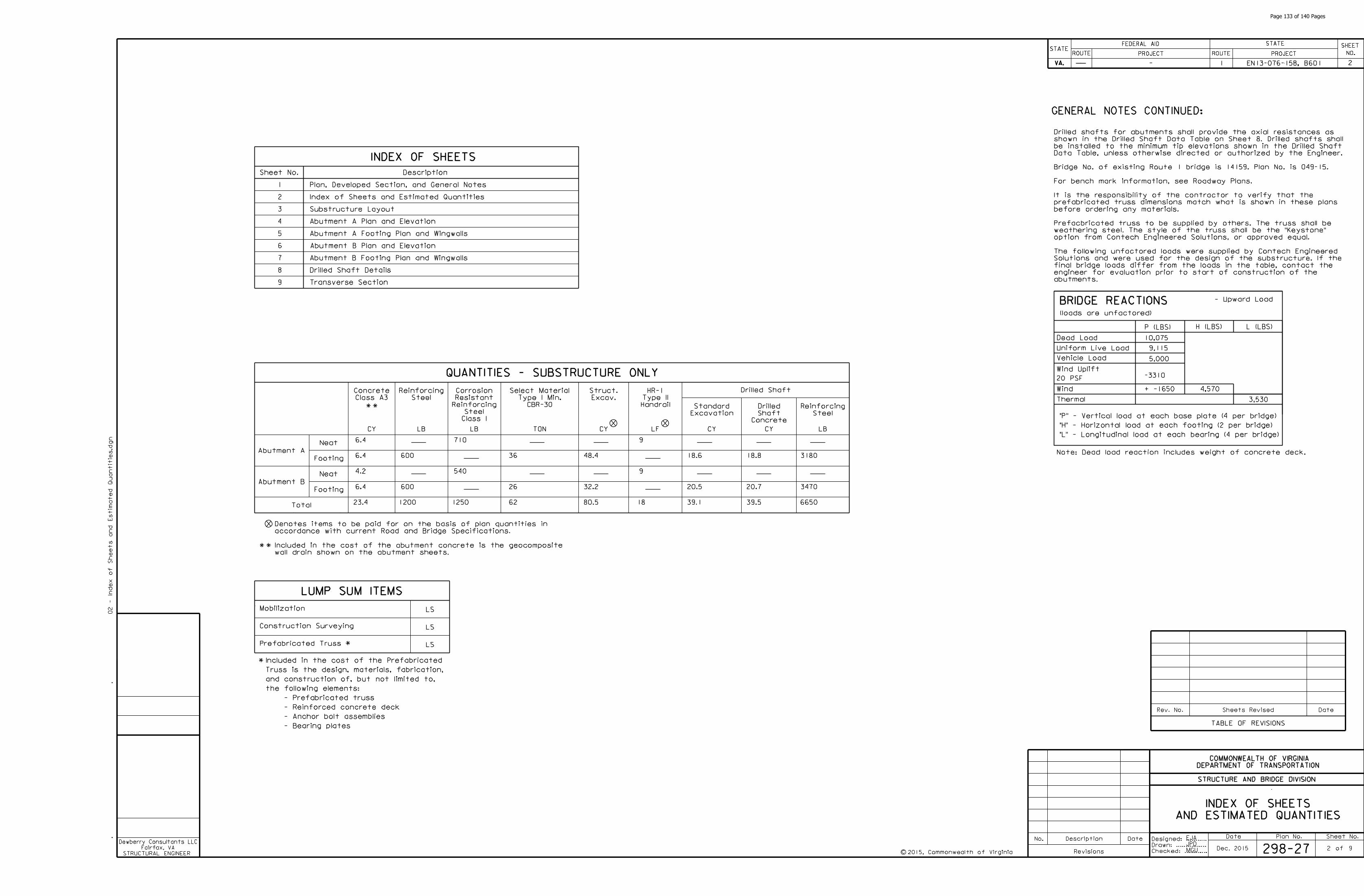
EJA
JPD2
Sheet No.
INDEX OF SHEETS
Description
Abutment B
Footing
Total
CY CY
Excav.
Struct.
Class A3
Concrete
QUANTITIES - SUBSTRUCTURE ONLY
CBR-30
Type I Min.
Select Material
TONLB
Mobilization
Construction Surveying
LS
LS
AND ESTIMATED QUANTITIES
INDEX OF SHEETS
Abutment A
DateSheets RevisedRev. No.
TABLE OF REVISIONS
1 Plan, Developed Section, and General Notes
2 Index of Sheets and Estimated Quantities
3 Substructure Layout
LUMP SUM ITEMS
5 Abutment A Footing Plan and Wingwalls
6 Abutment B Plan and Elevation
4 Abutment A Plan and Elevation
7 Abutment B Footing Plan and Wingwalls
8 Drilled Shaft Details
9 Transverse Section
2
Steel
Reinforcing
LB CY CY
Concrete
Shaft
Drilled
GENERAL NOTES CONTINUED:
LSPrefabricated Truss
LF
Handrail
Type II
HR-1
Footing
Neat
Neat
accordance with current Road and Bridge Specifications.
Denotes items to be paid for on the basis of plan quantities in
Class I
Steel
Reinforcing
Resistant
Corrosion
Excavation
Standard
6.4
6.4
4.2
6.4
23.4
Drilled Shaft
BRIDGE REACTIONS
P (LBS) H (LBS) L (LBS)
10,075
9,115
5,000
-3310
+ -1650
Uniform Live Load
Vehicle Load
Wind Uplift
20 PSF
Wind
Thermal
4,570
3,530
- Upward Load
"L" - Longitudinal load at each bearing (4 per bridge)
"H" - Horizontal load at each footing (2 per bridge)
"P" - Vertical load at each base plate (4 per bridge)
Dead Load
Note: Dead load reaction includes weight of concrete deck.
Steel
Reinforcing
LB
48.4
32.2
80.5
9
9
18
18.6
20.5
39.1
18.8
20.7
39.5
710
540
1250
600
600
1200
3180
3470
6650
36
26
62
- Bearing plates
- Anchor bolt assemblies
- Reinforced concrete deck
- Prefabricated truss
the following elements:
and construction of, but not limited to,
Truss is the design, materials, fabrication,
Included in the cost of the Prefabricated
MGU
wall drain shown on the abutment sheets.
Included in the cost of the abutment concrete is the geocomposite
(loads are unfactored)
abutments.
engineer for evaluation prior to start of construction of the
final bridge loads differ from the loads in the table, contact the
Solutions and were used for the design of the substructure. If the
The following unfactored loads were supplied by Contech Engineered
option from Contech Engineered Solutions, or approved equal.
weathering steel. The style of the truss shall be the "Keystone"
Prefacbricated truss to be supplied by others. The truss shall be
before ordering any materials.
prefabricated truss dimensions match what is shown in these plans
It is the responsibility of the contractor to verify that the
For bench mark information, see Roadway Plans.
Bridge No. of existing Route 1 bridge is 14159. Plan No. is 049-15.
Data Table, unless otherwise directed or authorized by the Engineer.
be installed to the minimum tip elevations shown in the Drilled Shaft
shown in the Drilled Shaft Data Table on Sheet 8. Drilled shafts shall
Drilled shafts for abutments shall provide the axial resistances as
298-27Dec. 2015
EN13-076-158, B601
STRUCTURAL ENGINEER
Dewberry Consultants LLC
Fairfax, VA
Date Plan No. Sheet No.Designed: ...........
Drawn: ................
Checked: ............2015, Commonwealth of Virginiac
No. Description Date
STRUCTURE AND BRIDGE DIVISION
COMMONWEALTH OF VIRGINIA
DEPARTMENT OF TRANSPORTATION
Revisions
ROUTE
FEDERAL AID
PROJECT ROUTE PROJECT
STATE SHEET
NO.
VA.
STATEROUTE
FEDERAL AID
PROJECT ROUTE PROJECT
STATE SHEET
NO.
VA.
STATE
02 - In
de
x of
Sheets and
Estim
ate
d
Quantitie
s.d
gn
of
- 1
9
Page 133 of 140 Pages

Scale: 1" = 5’-0"
SUBSTRUCTURE LAYOUT
footing and neatwork, see abutment sheets.
locating the footings of the abutments. For additional details of
The substructure layout is to be used only for the purpose of
Notes:
3
3
Back of backwall
Limits of side
walk appro
ach fill
Subgrade
Not to scale
Abutment drainage not shown
the Specifications
as per Section 305.03(a) of
Minimum density for top 6"
Benched
the VTM-10 test method.
accordance with Table II of
Minimum density 95% or in
Zone of select backfill material.
SECTION THROUGH ABUTMENT - FILL SECTION
1’-6"
structural excavation
To be paid for as
2’-1"
1’-0"
7’-
2" (A
but
me
nt
B)
8’-
9" (A
but
me
nt
A)
than the select backfill may be left in place.
In cut situations, material with strength characteristics greater
accordance with Sections 303 and 305 of the Specifications.
Select Material Type 1, minimum CBR 30 and shall be compacted in
Material in the abutment select backfill zone shall be 21A, 21B or
7’-2" (Abutment B)
8’-9" (Abutment A)
EJA
JPD
MGU 298-27Dec. 2015
EN13-076-158, B601
STRUCTURAL ENGINEER
Dewberry Consultants LLC
Fairfax, VA
Date Plan No. Sheet No.Designed: ...........
Drawn: ................
Checked: ............2015, Commonwealth of Virginiac
No. Description Date
STRUCTURE AND BRIDGE DIVISION
COMMONWEALTH OF VIRGINIA
DEPARTMENT OF TRANSPORTATION
Revisions
ROUTE
FEDERAL AID
PROJECT ROUTE PROJECT
STATE SHEET
NO.
VA.
STATEROUTE
FEDERAL AID
PROJECT ROUTE PROJECT
STATE SHEET
NO.
VA.
STATE
03 -
Substructure
Lay
out.d
gn
of
- 1
9
15BR-01 15BR-0215BR-03
54’-4"
o
N 35 -49’-35" Eo
Rte. 1 SidewalkLB
2’-
3�
"7’-
3�
"
1" 1"
6’-0"
W.P. #1
Face of backwall
Abutment A
Sta. 12+89.43
W.P. #2
Face of backwall
Abutment B
Sta. 13+43.77
2’-6"
7’-
3�
"2’-
3�
"
2’-6"
6’-0"
90 typ.
Drilled shaft typ.
SUBSTRUCTURE LAYOUT
2’-11" 2’-11"
Drilled shaftLCDrilled shaftLC
9’-
7"
9’-
7"
Page 134 of 140 Pages
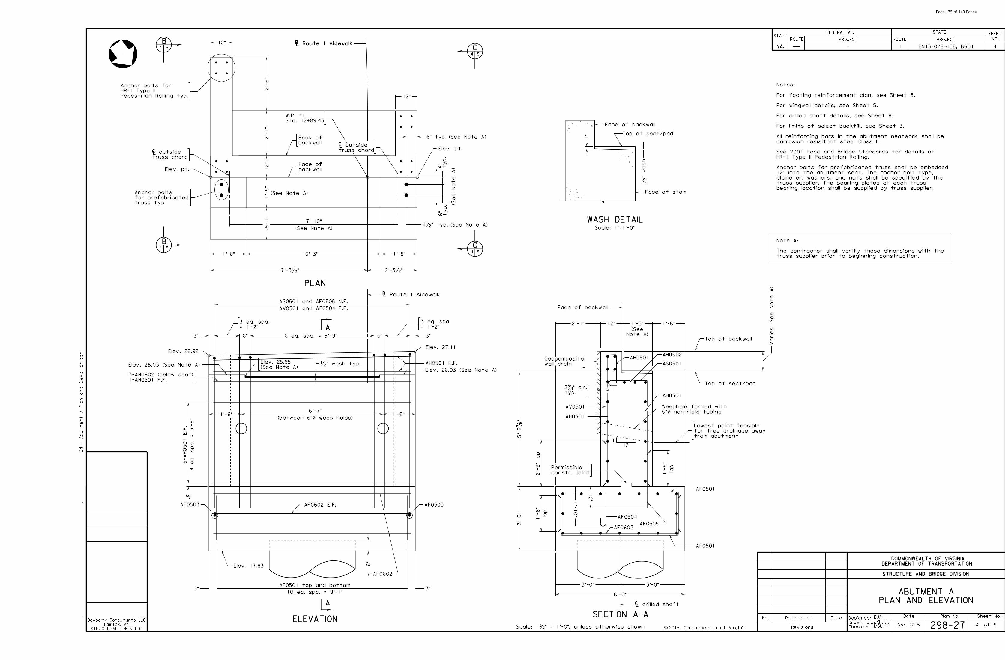
EJA
JPD4
PLAN AND ELEVATION
ABUTMENT A
4
Scale: �" = 1’-0", unless otherwise shown
truss supplier prior to beginning construction.
The contractor shall verify these dimensions with the
Note A:
bearing location shall be supplied by truss supplier.
truss supplier. The bearing plates at each truss
diameter, washers, and nuts shall be specified by the
12" into the abutment seat. The anchor bolt type,
Anchor bolts for prefabricated truss shall be embedded
HR-1 Type II Pedestrian Railing.
See VDOT Road and Bridge Standards for details of
corrosion resisitant steel Class I.
All reinforcing bars in the abutment neatwork shall be
For limits of select backfill, see Sheet 3.
For drilled shaft details, see Sheet 8.
For wingwall details, see Sheet 5.
For footing reinforcement plan. see Sheet 5.
Notes:
MGU 298-27Dec. 2015
EN13-076-158, B601
STRUCTURAL ENGINEER
Dewberry Consultants LLC
Fairfax, VA
Date Plan No. Sheet No.Designed: ...........
Drawn: ................
Checked: ............2015, Commonwealth of Virginiac
No. Description Date
STRUCTURE AND BRIDGE DIVISION
COMMONWEALTH OF VIRGINIA
DEPARTMENT OF TRANSPORTATION
Revisions
ROUTE
FEDERAL AID
PROJECT ROUTE PROJECT
STATE SHEET
NO.
VA.
STATEROUTE
FEDERAL AID
PROJECT ROUTE PROJECT
STATE SHEET
NO.
VA.
STATE
04 -
Abut
me
nt
A
Pla
n and
Ele
vatio
n.d
gn
of
- 1
9
Face of backwall
Top of seat/pad
1"
Face of stem
�"
wash
WASH DETAILScale: 1"=1’-0"
LB Route 1 sidewalk
Sta. 12+89.43
W.P. #1
LB Route 1 sidewalk
2’-3�"7’-3�"
PLAN
6’-3" 1’-8"1’-8"
truss chord
outside truss chord
outsideLC
LC
B4 5
B4 5
C
C4 5
4 5
12"
12"Pedestrian Railing typ.
HR-1 Type II
Anchor bolts for
Elev. pt.
truss typ.
for prefabricated
Anchor bolts
1’-
5"
12"
2’-
1"
2’-
6"
backwall
Back of
backwall
Face of
6" typ.
4�" typ.
Elev. 26.92Elev. 27.11
6"
Elev. 17.83
ELEVATION
A
3" 3"
1’-6"(between 6" weep holes)
6’-7"1’-6"
�" wash typ.
AA
3"3" 6 eq. spa. = 5’-9"
6"
= 1’-2"
3 eq. spa.
= 1’-2"
3 eq. spa.
6"
AH0501 E.F.
Face of backwall
1’-5"12"2’-1" 1’-6"
SECTION A-A
wall drain
Geocomposite
AV0501
AH0501
AS0501
AH0602
1’-
10"
12"
AF0501
AF0602
12
1
6" non-rigid tubing
Weephole formed with
o/
from abutment
for free drainage away
Lowest point feasible
1-AH0501 F.F.
3-AH0602 (below seat)
lap
1’-
8"
LB Route 1 sidewalk
AH0501
AF0504
AF0505
AF0503 AF0503
o/
1’-
6"
Elev. pt.
ty
p.
4"
ty
p.
6"
AV0501 and AF0504 F.F.
AS0501 and AF0505 N.F.
4 e
q.
spa.
= 3’-
9"
5-
AH0501
E.F.
AF0602 E.F.
7-AF0602
2’-
2" la
p
Top of seat/pad
typ.
2�" clr.
3"
constr. joint
Permissible
AH0501
AF0501
lap
1’-
8"
10 eq. spa. = 9’-1"
AF0501 top and bottom
7’-10"
(See Note A)
Elev. 26.03 (See Note A)(See Note A)
Elev. 25.95
Elev. 26.03 (See Note A)
Note A)
(See
Top of backwall
(See Note A)
(See Note A)
(See
Note
A)
(See Note A)
3’-0"3’-0"
6’-0"
LC drilled shaft
3’-
0"
5’-
2�
"
Varie
s (S
ee
Note
A)
Page 135 of 140 Pages
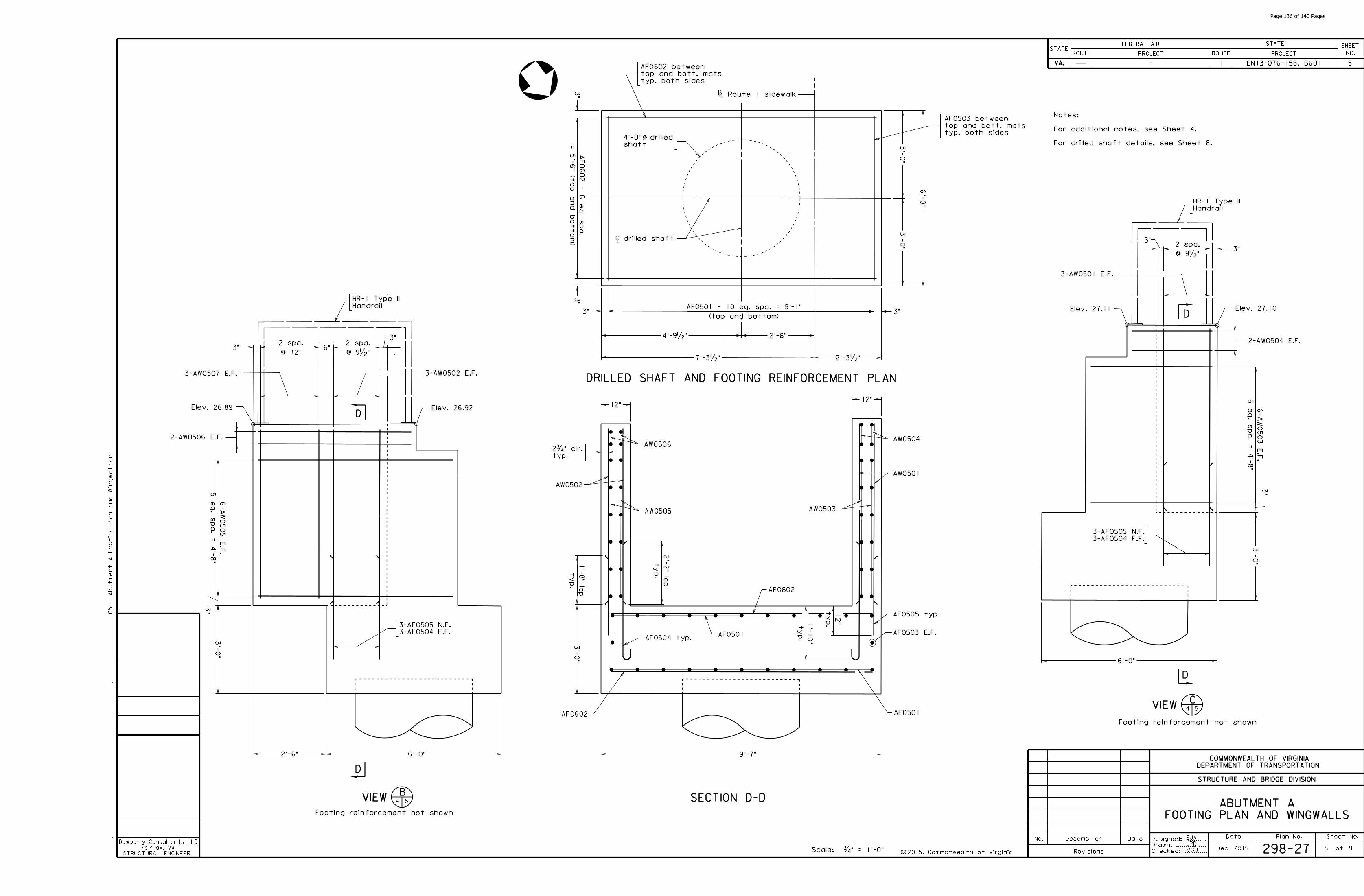
EJA
JPD5
5
Scale: �" = 1’-0"
FOOTING PLAN AND WINGWALLS
ABUTMENT A
For drilled shaft details, see Sheet 8.
For additional notes, see Sheet 4.
Notes:
MGU 298-27Dec. 2015
EN13-076-158, B601
STRUCTURAL ENGINEER
Dewberry Consultants LLC
Fairfax, VA
Date Plan No. Sheet No.Designed: ...........
Drawn: ................
Checked: ............2015, Commonwealth of Virginiac
No. Description Date
STRUCTURE AND BRIDGE DIVISION
COMMONWEALTH OF VIRGINIA
DEPARTMENT OF TRANSPORTATION
Revisions
ROUTE
FEDERAL AID
PROJECT ROUTE PROJECT
STATE SHEET
NO.
VA.
STATEROUTE
FEDERAL AID
PROJECT ROUTE PROJECT
STATE SHEET
NO.
VA.
STATE
05 -
Abut
me
nt
A
Fo
otin
g
Pla
n and
Win
gwall.d
gn
of
- 1
9
SECTION D-D
7’-3�" 2’-3�"
6’-
0"
9’-7"
3’-
0"
LB Route 1 sidewalk
typ. both sides
top and bott. mats
AF0602 between
3"
3"
= 5’-
6" (t
op and botto
m)
AF0602 - 6 e
q.
spa.
3"3"
AF0602
AF0602
ty
p.
12"
ty
p.
1’-
10"
AW0505
AW0506
AW0503
AW0504
typ. both sides
top and bott. mats
AF0503 between
(top and bottom)
AF0501 - 10 eq. spa. = 9’-1"
AF0503 E.F.
D
VIEWB
4 5
Footing reinforcement not shown
D
6’-0"2’-6"
Elev. 26.89 Elev. 26.92
3’-
0"
2-AW0506 E.F.
Handrail
HR-1 Type II
3-AW0507 E.F.
3’-
0"
3’-
0"
4’-9�"
o/
shaft
4’-0" drilled
3"@ 12"
2 spa.6"
@ 9�"
2 spa.
5 e
q.
spa.
= 4’-
8"
6-
AW
0505
E.F.
AF0505 typ.
AF0504 typ.
ty
p.
2’-
2" la
p
ty
p.
1’-
8" la
p
3"
3"
typ.
2�" clr.
DRILLED SHAFT AND FOOTING REINFORCEMENT PLAN
2’-6"
AF0501
AF05013-AF0504 F.F.
3-AF0505 N.F.
3-AW0502 E.F.
AW0501
AW0502
12"12"
drilled shaftLC
DElev. 27.11 Elev. 27.10
6’-0"
VIEWC
4 5
Footing reinforcement not shown
D
Handrail
HR-1 Type II
2-AW0504 E.F.
3’-
0"
3"@ 9�"
2 spa.
5 e
q.
spa.
= 4’-
8"
6-
AW
0503
E.F.
3"
3"
3-AF0504 F.F.
3-AF0505 N.F.
3-AW0501 E.F.
Page 136 of 140 Pages
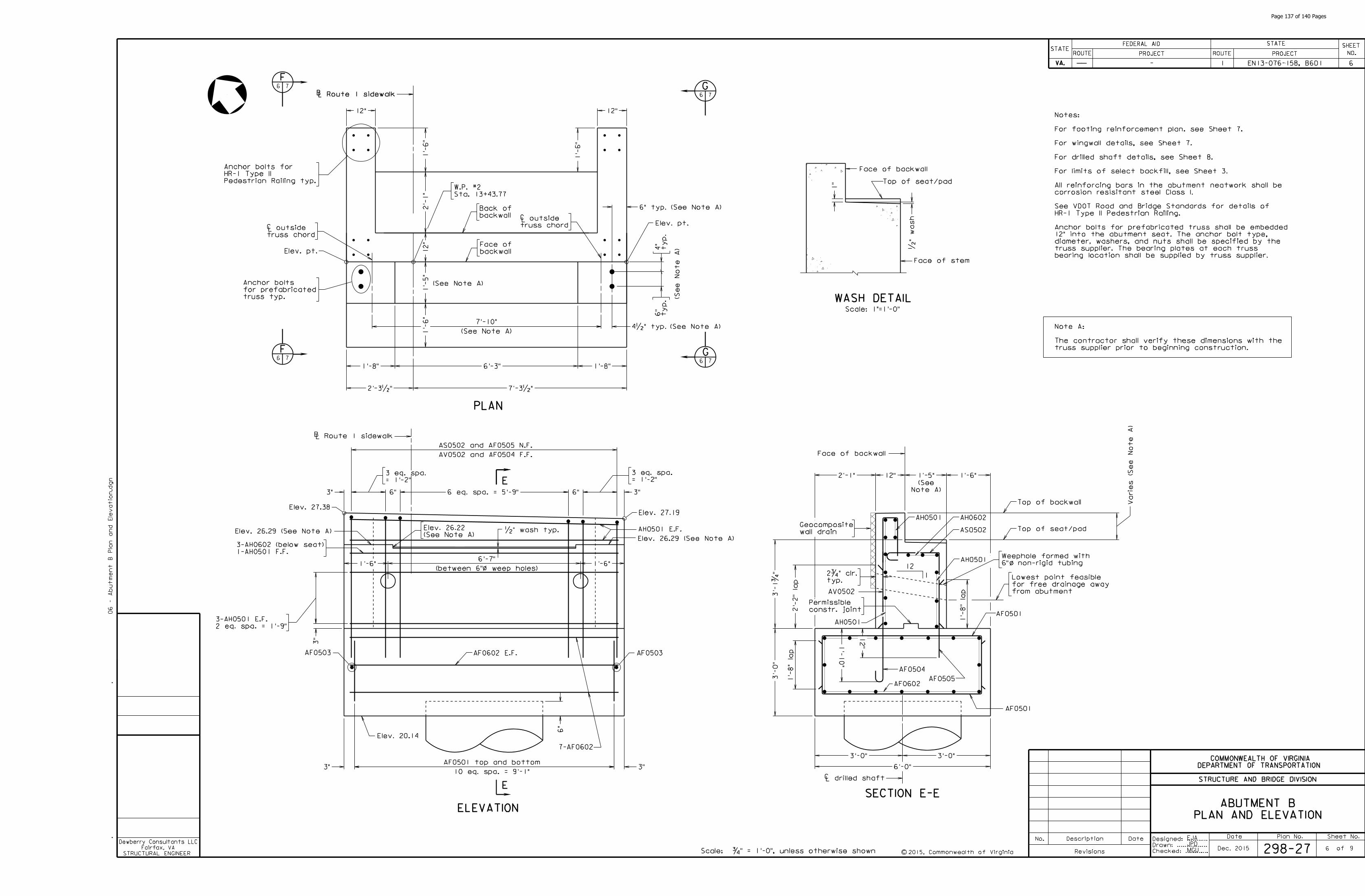
EJA
JPD6
PLAN AND ELEVATION
ABUTMENT B
6
Scale: �" = 1’-0", unless otherwise shown
truss supplier prior to beginning construction.
The contractor shall verify these dimensions with the
Note A:
bearing location shall be supplied by truss supplier.
truss supplier. The bearing plates at each truss
diameter, washers, and nuts shall be specified by the
12" into the abutment seat. The anchor bolt type,
Anchor bolts for prefabricated truss shall be embedded
HR-1 Type II Pedestrian Railing.
See VDOT Road and Bridge Standards for details of
corrosion resisitant steel Class I.
All reinforcing bars in the abutment neatwork shall be
For limits of select backfill, see Sheet 3.
For drilled shaft details, see Sheet 8.
For wingwall details, see Sheet 7.
For footing reinforcement plan. see Sheet 7.
Notes:
MGU 298-27Dec. 2015
EN13-076-158, B601
STRUCTURAL ENGINEER
Dewberry Consultants LLC
Fairfax, VA
Date Plan No. Sheet No.Designed: ...........
Drawn: ................
Checked: ............2015, Commonwealth of Virginiac
No. Description Date
STRUCTURE AND BRIDGE DIVISION
COMMONWEALTH OF VIRGINIA
DEPARTMENT OF TRANSPORTATION
Revisions
ROUTE
FEDERAL AID
PROJECT ROUTE PROJECT
STATE SHEET
NO.
VA.
STATEROUTE
FEDERAL AID
PROJECT ROUTE PROJECT
STATE SHEET
NO.
VA.
STATE
06 -
Abut
me
nt
B
Pla
n and
Ele
vatio
n.d
gn
of
- 1
9
Face of backwall
Top of seat/pad
1"
Face of stem
�"
wash
WASH DETAILScale: 1"=1’-0"
LB Route 1 sidewalk
Sta. 13+43.77
W.P. #2
LB Route 1 sidewalk
PLAN
truss chord
outside truss chord
outsideLC
LC
F6 7
F6 7
G
G6 7
6 7
Pedestrian Railing typ.
HR-1 Type II
Anchor bolts for
Elev. pt.
truss typ.
for prefabricated
Anchor bolts
backwall
Back of
backwall
Face of
Elev. 27.38Elev. 27.19
Elev. 20.14
ELEVATION
E
�" wash typ.
E = 1’-2"
3 eq. spa.
= 1’-2"
3 eq. spa.
AH0501 E.F.
Face of backwall
SECTION E-E
wall drain
Geocomposite
AV0502
AH0501
AS0502
AH0602
AF0501
AF0602
12
1
6" non-rigid tubing
Weephole formed with
o/
from abutment
for free drainage away
Lowest point feasible
1-AH0501 F.F.
3-AH0602 (below seat)
LB Route 1 sidewalk
AH0501
AF0504
AF0505
AF0503 AF0503
o/
Elev. pt.
ty
p.
4"
ty
p.
6"
AF0602 E.F.
7-AF0602
Top of seat/pad
typ.
2�" clr.
constr. joint
Permissible
AH0501
AF0501
1’-8"6’-3"1’-8"
2’-3�" 7’-3�"
4�" typ.
6" typ.
12"
1’-
6"
1’-
6"
2’-
1"
12"
1’-
5"
12"
AV0502 and AF0504 F.F.
AS0502 and AF0505 N.F.
3"
6"6 eq. spa. = 5’-9"6"3"
1’-6"(between 6" weep holes)
6’-7"1’-6"
6"
3"3"
1’-5" 1’-6"2’-1" 12"
2’-
2" la
p1’-
8" la
p
3’-
0"
12"1’-
10"
1’-
8" la
p
3"
2 eq. spa. = 1’-9"
3-AH0501 E.F.
10 eq. spa. = 9’-1"
AF0501 top and bottom
(See Note A)
(See Note A)
(See Note A)
(See Note A)
7’-10"
1’-
6"
(See
Note
A)
Elev. 26.29 (See Note A)(See Note A)
Elev. 26.22
Elev. 26.29 (See Note A)
Note A)
(See
Top of backwall Varie
s (S
ee
Note
A)
LC drilled shaft
6’-0"
3’-0"3’-0"
3’-
1�
"
Page 137 of 140 Pages
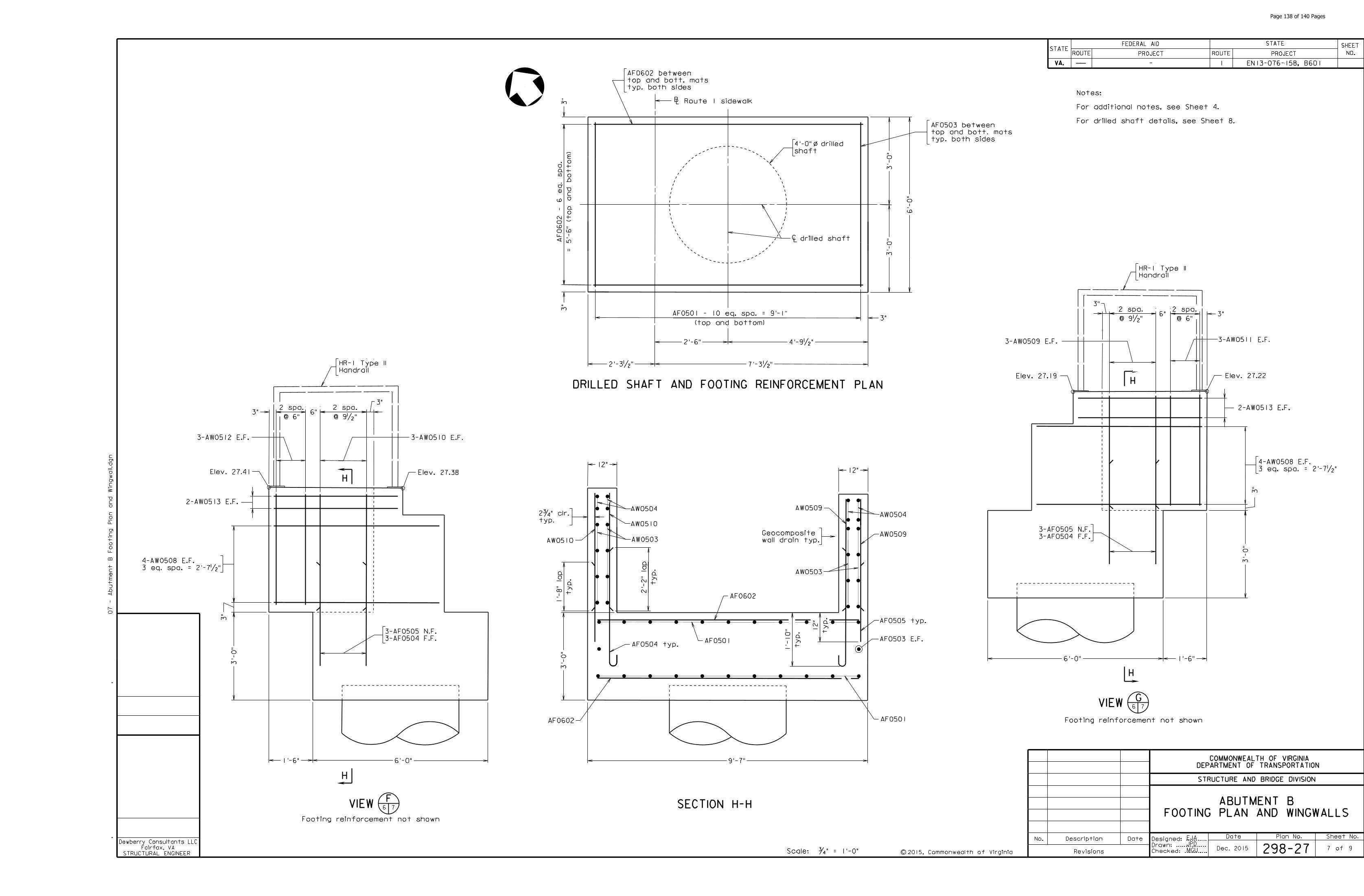
EJA
JPD7
Scale: �" = 1’-0"
FOOTING PLAN AND WINGWALLS
ABUTMENT B
For drilled shaft details, see Sheet 8.
For additional notes, see Sheet 4.
Notes:
MGU 298-27Dec. 2015
EN13-076-158, B601
STRUCTURAL ENGINEER
Dewberry Consultants LLC
Fairfax, VA
Date Plan No. Sheet No.Designed: ...........
Drawn: ................
Checked: ............2015, Commonwealth of Virginiac
No. Description Date
STRUCTURE AND BRIDGE DIVISION
COMMONWEALTH OF VIRGINIA
DEPARTMENT OF TRANSPORTATION
Revisions
ROUTE
FEDERAL AID
PROJECT ROUTE PROJECT
STATE SHEET
NO.
VA.
STATEROUTE
FEDERAL AID
PROJECT ROUTE PROJECT
STATE SHEET
NO.
VA.
STATE
07 -
Abut
me
nt
B
Fo
otin
g
Pla
n and
Win
gwall.d
gn
of
- 1
9
HElev. 27.19 Elev. 27.22
VIEWG
6 7
Footing reinforcement not shown
H
Handrail
HR-1 Type II
2-AW0513 E.F.
3’-
0"
3-AW0511 E.F.
6’-0" 1’-6"
3"
3 eq. spa. = 2’-7�"
4-AW0508 E.F.
3"
3"6"@ 6"
2 spa.
@ 9�"
2 spa.
3-AF0504 F.F.
3-AF0505 N.F.
3-AW0509 E.F.
SECTION H-H
6’-
0"
3’-
0"
LB Route 1 sidewalk
typ. both sides
top and bott. mats
AF0602 between
3"
3"
= 5’-
6" (t
op and botto
m)
AF0602 - 6 e
q.
spa.
AF0602
AF0602
ty
p.
12"
ty
p.
1’-
10"
AW0503
AW0504
AW0503
AW0504
typ. both sides
top and bott. mats
AF0503 between
AF0503 E.F.
wall drain typ.
Geocomposite
H
VIEWF
6 7
Footing reinforcement not shown
H
Elev. 27.41 Elev. 27.38
3’-
0"
2-AW0513 E.F.
Handrail
HR-1 Type II
3-AW0512 E.F.
3’-
0"
3’-
0"
o/
shaft
4’-0" drilled
AF0505 typ.
AF0504 typ.
ty
p.
2’-
2" la
p
ty
p.
1’-
8" la
p
3"
typ.
2�" clr.
DRILLED SHAFT AND FOOTING REINFORCEMENT PLAN
AF0501
AF0501
3"(top and bottom)
AF0501 - 10 eq. spa. = 9’-1"
2’-3�"
2’-6" 4’-9�"
7’-3�"
1’-6" 6’-0" 9’-7"
3" 6"@ 6"
2 spa.
@ 9�"
2 spa.
3"
3 eq. spa. = 2’-7�"
4-AW0508 E.F.
AW0509
AW0509
AW0510
3-AF0504 F.F.
3-AF0505 N.F.
3-AW0510 E.F.
AW0510
12"12"
drilled shaftLC
Page 138 of 140 Pages

JPD
Elevation A
Top of shaft
Elevation B
Minimum Shaft Tip
ELEVATIONS
DRILLED SHAFT DATA
8
8
Ties K
Number of
Not to scale
Resistance
Axial
Factored
Minimum
Description
Resistance
Lateral
Factored
Minimum
SFY
Abut. B
Abut. A
12
15
-23.86
-22.17
46
42
All reinforcing bars in the drilled shafts shall be black steel.
For abutment details, see sheets 4 thru 7.
Notes:
20.64
18.33
EJA
170
150
DRILLED SHAFT DETAILS
All loads are in tons and elevations are in feet. The Strength III Limit State controls the drilled shaft design.
298-27Dec. 2015
EN13-076-158, B601
STRUCTURAL ENGINEER
Dewberry Consultants LLC
Fairfax, VA
Date Plan No. Sheet No.Designed: ...........
Drawn: ................
Checked: ............2015, Commonwealth of Virginiac
No. Description Date
STRUCTURE AND BRIDGE DIVISION
COMMONWEALTH OF VIRGINIA
DEPARTMENT OF TRANSPORTATION
Revisions
ROUTE
FEDERAL AID
PROJECT ROUTE PROJECT
STATE SHEET
NO.
VA.
STATEROUTE
FEDERAL AID
PROJECT ROUTE PROJECT
STATE SHEET
NO.
VA.
STATE
08 -
Drille
d
Shaft
Details.d
gn
of
- 1
9
TYPICAL DRILLED SHAFT ELEVATION
6"
6"
Elev. B
B B
A A
LC
Elev. A
shaft
Top of
3’-
0"
Bottom of footing
Tip elevation
drilled shaft
DV09 series
K-
DS0401
@ 12"
max.
Drilled shaft
4’-0" dia. Standard e
xcavatio
nStructure e
xcavatio
n
See abut
me
nt sheets
min.
2’-
7"
SECTION A-A
LC
LC
DS0401
drilled shaft
CSL tube typ.
2" dia. steel
2’-
2"
min. la
p
3�" cl.
19-DV09 series
4’-0"
2’-0"2’-0"
drilled shaft
VIEW B-B
SECTION A-A
LC
LC drilled shaft
19-DV09 series
4’-0"
2’-0"2’-0"
drilled shaft
Abutment footing reinforcement not shown for clarity.
Page 139 of 140 Pages

Scale: 1�" = 1’-0"
EJA
JPD
TRANSVERSE SECTION
9
concrete deck.
and should be between 2’-10" and 3’-2" above the top of the
The top of the gripping surface of the handrails shall be level
deck shall be provided by the truss supplier.
design and detailing of the reinforcement in the concrete
Reinforcing steel in the concrete slab shall be CRR Class I. The
Prefabricated truss will be supplied by others.
Notes:
MGU 298-27Dec. 2015
EN13-076-158, B601
STRUCTURAL ENGINEER
Dewberry Consultants LLC
Fairfax, VA
Date Plan No. Sheet No.Designed: ...........
Drawn: ................
Checked: ............2015, Commonwealth of Virginiac
No. Description Date
STRUCTURE AND BRIDGE DIVISION
COMMONWEALTH OF VIRGINIA
DEPARTMENT OF TRANSPORTATION
Revisions
ROUTE
FEDERAL AID
PROJECT ROUTE PROJECT
STATE SHEET
NO.
VA.
STATEROUTE
FEDERAL AID
PROJECT ROUTE PROJECT
STATE SHEET
NO.
VA.
STATE
09 -
Transverse
Sec.d
gn
of
- 1
9
7’-6"
TRANSVERSE SECTION
6’-3"1’-3"
LB
See note ty
p. f
or both handrails
Existing Route 1 bridge
Deck form
Concrete deck
Rte. 1 sidewalk
Handrail
4’-
6"
min. ty
p.
2.0% slope
7’-0" min. between handrails
Face of truss chordFace of truss chord
Page 140 of 140 Pages