geotechnical report – concept design stage
TRANSCRIPT

Art Gallery of NSW Trust
Art Gallery of NSW Expansion - Sydney Modern
Geotechnical Report – Concept Design Stage

This page has been left intentionally blank

i
Art Gallery of NSW Expansion Project
Prepared for Art Gallery of NSW Trust 1 Art Gallery Road Sydney NSW 2000
Prepared by Coffey Geotechnics Pty Ltd Level 19, Tower B, 799 Pacific Highway Chatswood NSW 2067 Australia t: 02 9406 1000 f:02 9415 1678 ABN: 93 056 929 483
Document authorisation
Project ref: GEOTLCOV25037AA
Original issue: 27 September 2017
Revision issue: 24 October 2017
For and on behalf of Coffey
Robert Turner Principal Geotechnical Engineer
Revision history
Report ref Description Status Issued Author Reviewer Signatory
GEOTLCOV 25037AA-AF rev1
Geotechnical Investigation – Feasibility Stage
Final 13 Jun 2014 DS PJW PJW
GEOTLCOV 25037AA-AF rev 2
Geotechnical Investigation – Concept Stage
Draft 27 Sep 2017 RC RMT RC
GEOTLCOV 25037AA-AF rev 2
Geotechnical Investigation – Concept Stage
Final 11 Oct 2017 RC RMT RC
GEOTLCOV 25037AA-AF rev 3
Geotechnical Investigation – Concept Stage (minor corrections)
Final 24 Oct 2017 RMT - RMT

ii
Table of contents 1. Introduction .................................................................................................................................. 1 2. Site Information ........................................................................................................................... 2
2.1. Location ............................................................................................................................. 2 2.2. Terrain ............................................................................................................................... 3 2.3. Geology ............................................................................................................................. 3 2.4. Fuel Bunkers ..................................................................................................................... 5
3. Geotechnical Investigation 2014 ................................................................................................. 6 3.1. Drilling ............................................................................................................................... 6 3.2. Laboratory Testing ............................................................................................................ 7 3.3. Subsurface conditions encountered .................................................................................. 7 3.4. Interpreted geotechnical model ......................................................................................... 8 3.5. Groundwater...................................................................................................................... 9
4. Discussion and Recommendations ............................................................................................. 9 4.1. Preamble ........................................................................................................................... 9 4.2. Excavation ....................................................................................................................... 10
4.2.1. Excavation Equipment and Vibrations ............................................................... 10 4.2.2. Groundwater ....................................................................................................... 10 4.2.3. Excavation and Support for Units 1 and 2a........................................................ 11 4.2.4. Excavation and Support for Units 2b, 2c and 2d ................................................ 12 4.2.5. Rock pillar between gallery and eastern distributor ........................................... 12 4.2.6. Rock Anchors ..................................................................................................... 13
4.3. Foundations..................................................................................................................... 13 4.4. Seismic Design................................................................................................................ 14 4.5. Potential impacts on adjacent structures & services....................................................... 15 4.6. Acid Sulfate Soils ............................................................................................................ 15 4.7. Soil Aggressivity .............................................................................................................. 15
5. Closing Comments .................................................................................................................... 15
Important information about your Coffey Report
Figures Figure 1 Geotechnical Investigation Location Plan
Figures 2 - 4 Interpreted Cross Sections
Appendices
Appendix A: Engineering Borehole Logs, Core Photographs and Explanation Sheets
Appendix B: Laboratory Testing Results
Appendix C: Architect’s plans and sections

Geotechnical Report to support SSDA – Art Gallery of NSW Sydney Modern Expansion Project
Coffey GEOTLCOV25037AA-AF rev3 24 October 2017
1
1. Introduction The Art Gallery of NSW proposes to undertake a major expansion of the existing art gallery adjacent to the Phillip Precinct of the Domain. The expansion, proposed as a separate, stand-alone building, is located north of the existing gallery, partly extending over the Eastern Distributor land bridge and includes a disused Navy fuel bunker located to the north east of this land bridge.
The new building comprises a new entry plaza, new exhibition spaces, shop, food and beverage facilities, visitor amenities, art research and education spaces, new roof terraces and landscaping and associated site works and infrastructure, including loading and service areas, services infrastructure and an ancillary seawater heat exchange system.
Sketch 1 – Proposed new gallery layout
In June 2014, Coffey Geotechnics Pty Ltd prepared a geotechnical investigation report (reference GEOTLCOV25037AA-AF rev1) to assist in the early feasibility design of the expansion project. At that time the concept outlined in the above sketch had not been developed, so our report provided general advice to assist planning.
This document updates the original Coffey feasibility investigation report. It has been prepared to support the State Significant Development Application for the Sydney Modern Project. It presents the results of our previous geotechnical investigation, with geotechnical recommendations and discussion that pertain to the concept design. The report provides a geotechnical model for the site, and discussions and recommendations for the design of excavations, retention systems and building foundations and management of potential impacts on existing structures.
This report for the concept design stage was first issued on 27 September 2017, and issued as final on 11 October 2017. At that time, Coffey had interpreted that some excavation below existing bunker floor level was proposed. This revision corrects that misinterpretation and removes previous Section 4.6 (building over existing anchors) which is not relevant to the current development proposal.

Geotechnical Report to support SSDA – Art Gallery of NSW Sydney Modern Expansion Project
Coffey GEOTLCOV25037AA-AF rev3 24 October 2017
2
The original investigation was commissioned by The Gallery through Gale Planning Group Pty Ltd and was carried out generally in accordance with our proposals GEOTLCOV25037AA-AA dated 28 January 2014 and GEOTLCOV25037AA-AB dated 4 February 2014. This revision was conducted as an extension to that commission.
A Stage 1 preliminary environmental study, limited soil investigation and preliminary waste classification assessment was also carried out by Coffey. The results are presented in a separate report (Ref GEOTLCOV25037AC-R01 Rev2, dated 25 September 2017).
2. Site Information 2.1. Location The site is located to the north of the existing Gallery building, on the eastern side of Art Gallery Road, Sydney, NSW. The site extends over the existing Eastern Distributor land bridge (the backfilled tunnel roof above the Eastern Distributor carriageway) to the former Woolloomooloo fuel bunkers located to the west of Lincoln Crescent. The fuel bunker was excavated into the hillside, with a concrete gravity wall exposed along Lincoln Crescent.
The development site and position of the land bridge and fuel bunker are shown on Sketch 2 below.
Sketch 2 – Existing site layout

Geotechnical Report to support SSDA – Art Gallery of NSW Sydney Modern Expansion Project
Coffey GEOTLCOV25037AA-AF rev3 24 October 2017
3
2.2. Terrain The ground levels south of the land bridge vary from about RL 24 m to RL 23 m near Art Gallery Road to RL 19 m dipping to the south east. To the north of the land bridge, the ground is sloping down to the fuel bunker area. The ground level varied from about RL 23 m (Art Gallery Road level) to RL 15 m and then a 5 m high cliff is located just before the fuel bunker area where the ground elevation flattens to about RL 9 m. Lincoln Crescent is a further step down at about RL 2.7 m.
Medium to large trees are located on either side of the land bridge. Garden beds are located on the northern side of the land bridge. The roof of the fuel bunkers is covered with grass. Stairs are located on the northern side of the land bridge. A concrete footpath is located along the crest of the cliff that leads to Lincoln Crescent footbridge
2.3. Geology The Sydney 1:100,000 Geological Sheet indicates the locality is underlain by Hawkesbury Sandstone described as medium to coarse grained quartz sandstone with very minor shale and laminite lenses.
Sandstone bedrock was exposed on the cliff face at the eastern boundary of the fuel bunkers and along Eastern Distributor and intersection of Lincoln Crescent and Cowper Wharf Road.
Photograph 1: Rock outcrops near the fuel bunker area

Geotechnical Report to support SSDA – Art Gallery of NSW Sydney Modern Expansion Project
Coffey GEOTLCOV25037AA-AF rev3 24 October 2017
4
Photograph 2: Along Eastern Distributor
Photograph 3: Lincoln Crescent where the fuel bunker wall intersects the rock cutting.

Geotechnical Report to support SSDA – Art Gallery of NSW Sydney Modern Expansion Project
Coffey GEOTLCOV25037AA-AF rev3 24 October 2017
5
2.4. Fuel Bunkers The fuel bunkers comprise two connected ‘rooms’ (bunkers) each about 40 m by 50 m in footprint, located as shown on Figure 1. The floor level of the bunkers is about RL 0.7 m. The fuel bunkers are roofed with concrete slabs at about RL 9 m.
Coffey carried out ground penetrating radar (GPR) survey at the fuel bunkers to assess the lateral extent of the bunkers and identify concrete columns inside the bunkers (supporting the roof). The results of the GPR survey were reported in Ref: GEOTLCOV25037AA-AD, dated 14 March 2014 and GEOTLCOV25037AA-AD Addendum 1, dated 28 March 2014.
In 2016, Coffey prepared a Fuel Bunker Inflow Assessment (Ref. GEOTLCOV25037AB-AE dated 15 July 2016), assessing sources and rates of water inflow into the bunkers. That report has been used to assess groundwater conditions in the vicinity the bunker.
In September 2017, Coffey was provided with historical photographs of the fuel bunker construction, including rock excavation photographs.
Photograph 4: Fuel bunker excavation historical photographs

Geotechnical Report to support SSDA – Art Gallery of NSW Sydney Modern Expansion Project
Coffey GEOTLCOV25037AA-AF rev3 24 October 2017
6
Photograph 5: Fuel bunker excavation historical photographs
3. Geotechnical Investigation 2014 3.1. Drilling Nine boreholes (BH01 to BH08 and BH02a) were drilled between 8 and 24 April 2014. Figure 1 shows the borehole locations. The boreholes, except for BH02 and BH05, were drilled to nominal depths of 20 m below the existing ground. BH02 and BH05 were terminated to 1.5 m to 2 m below the ground surface due to obstructions encountered in the boreholes.
Most of the boreholes were drilled using Drillcat, a track mounted drilling rig. BH01 and BH05 were drilled using XC Drill, a track mounted drilling rig suitable for limited access sites.
For boreholes located on concrete paving, a diatube was used to core the concrete. Boreholes were advanced through soils using solid flight augers with a Tungsten Carbide (TC) drill bit. Standard Penetration Tests were carried out at intervals to assess soil strength. Environmental soil samples were also collected at selected intervals in the boreholes. Boreholes were continued into sandstone bedrock using NMLC coring techniques. On completion, boreholes were backfilled with cuttings.
The drilling operations were monitored by a Coffey Geotechnical Engineer who carried out sampling and testing, recorded test results, photographed rock cores, and logged materials encountered. The borehole locations were recorded using tape measurements from site features and the reduced levels were interpolated from a supplied survey drawing.

Geotechnical Report to support SSDA – Art Gallery of NSW Sydney Modern Expansion Project
Coffey GEOTLCOV25037AA-AF rev3 24 October 2017
7
3.2. Laboratory Testing The following laboratory tests were carried out on selected soil and rock samples:
• Point Load Strength Index tests on rock cores at approximately 1m intervals.
• Four pH, sulfate and chloride tests on soil samples to aid in the assessment of aggressiveness of the soils to concrete and steel.
Point Load Strength Index test results are included on the borehole logs in Appendix A.
The test certificates for chemical testing (pH, Sulfate and Chloride) are presented in Appendix B1 and summarised below.
• pH values of 7.8 to 8.4;
• Chloride levels of <10 mg/kg; and
• Sulfate concentrations of <10 mg/kg to 43 mg/kg.
3.3. Subsurface conditions encountered The engineering borehole logs and rock core photographs are presented in Appendix A, together with Coffey soil and rock explanation sheets which describe the terms and symbols used in log preparation. Figures 2 to 4 present interpreted sections along the southern side of the land bridge (Figure 2), along the northern side of the land bridge (Figure 3) and along Art Gallery Road (Figure 4).
Fill Materials
On the southern side of the land bridge, BH06 and BH07 penetrated fill thicknesses less than 1 m and BH08 drilled on a paved area encountered 0.1 m thick tile and 0.5 m thick concrete over sandstone.
Boreholes BH01 to BH05 and BH02a drilled on the northern side of the land bridge encountered thicker fill, 1.25 m to 3.2 m thick. Fill was generally described as sandy materials.
Residual Soil
Residual soil derived from weathering of the underlying bedrock was not encountered, but may occur between borehole locations.
Bedrock
Sandstone bedrock was generally moderately to slightly weathered and medium strength. Where bedding parting and jointing were encountered, a more weathered, lower strength and iron stained sandstone was observed. In BH01, BH02a, BH03 and BH07, a layer of extremely to highly weathered, very low to low strength sandstone was encountered below the fill. With increasing depth the sandstone becomes slightly weathered to fresh, and medium to high strength.
1 Test certificates in Appendix B also include results from laboratory testing for waste classification purposes that is reported separately. Soil aggressivity test results are shown on pages 3 and 5 of the test result certificates.

Geotechnical Report to support SSDA – Art Gallery of NSW Sydney Modern Expansion Project
Coffey GEOTLCOV25037AA-AF rev3 24 October 2017
8
3.4. Interpreted geotechnical model Table 1 presents a generalised description of the geotechnical units identified in the investigation. The rock units are classified using the Pells et al. rock mass classification system (refer Note 1, Table 1), which considers rock strength, defect type and spacing, and is widely used in the Sydney region.
Table 1: Geotechnical Units
Unit Material Description Approximate Unit Thickness2 (m)
1 Fill Sandy Fill. Tile and concrete 0.6 m thick in BH08 only 0.6 – 3.2
2a Bedrock Class V / Class IV Sandstone1: extremely to highly weathered, very low to low strength, absent in some boreholes. 0 – 4.0
2b Bedrock Class III Sandstone1: moderately to slightly weathered, medium strength with 0.8 m to 3.4 m thick Class IV Sandstone1 interbeds where bedding parting and jointing were encountered
5.8 – >18.75 Not penetrated in some boreholes
2c Bedrock Class II Sandstone1: moderately weathered to fresh, medium to high strength, encountered in BH01, BH06, BH07 and BH08 only Up to 5.5
2d Bedrock Class I Sandstone1: generally fresh with some moderately to slightly weathered layer, high strength, encountered in BH01 only
Not Penetrated
Notes: 1. Rock classified as shale in accordance with Pells et al (1998) “Foundations on Sandstone and Shale in the Sydney Region” Aust. Geomech. Jnl, Dec 1998.
2. The layer thicknesses provided above are based on subsurface conditions as observed at the borehole locations and may not be representative of all areas of the site.
A Geotechnical Model has been developed for three site areas where the Geotechnical units were encountered at varying elevations. These areas are:
• South (city-side) of the land bridge (BH06, BH07 and BH08);
• North (Botanic Gardens-side) of the land bridge (BH02a, BH03, and BH04), and;
• Near the intersection of Lincoln Crescent and Cowper Wharf Road (BH01).
Table 2 presents a summary of the Geotechnical Models in these three areas.
Table 2: Geotechnical Models
Geotechnical Unit RL to Top of Unit (m AHD)
South of Land Bridge North of Land Bridge Near intersection of
Lincoln Crescent and Cowper Wharf Road
Unit 1 - Fill 24.5 – 21.2 Surface / 22.2 – 18.3 Surface / 11.4
Unit 2a - Class V/IV Sandstone 23.7 Encountered BH07 only
17.2 – 16.4 Absent in BH04 3.2 / 8.2
Unit 2b Class III Sandstone 23.4 – 20.3 21.0 – 13.2 7.6
Unit 2c Class II Sandstone 8.3 – 5.6 Not encountered in the boreholes 1.8
Unit 2d Class I Sandstone Not encountered in the boreholes
Not encountered in the boreholes - 3.7

Geotechnical Report to support SSDA – Art Gallery of NSW Sydney Modern Expansion Project
Coffey GEOTLCOV25037AA-AF rev3 24 October 2017
9
3.5. Groundwater Groundwater was not encountered during augering in soil. Generally, groundwater was not monitored during coring of sandstone as water was used as drilling fluid while coring the rock.
In BH04, BH06 and BH08, where rock coring was carried out for over a day, groundwater level was measured on the second day prior to commencing coring. Groundwater levels of 8.3 m to 12 m below the ground surface or RL 12.3 m to RL 13.2 m were measured in the boreholes.
The exposed sandstone along the Eastern Distributor, intersection of Lincoln Crescent and Cowper Wharf Road, and the cliff face at the eastern boundary of the fuel bunker appeared to be dry.
From the Fuel Bunker Inflow Assessment Report (Ref. GEOTLCOV25037AB-AE dated 15 July 2016) groundwater levels between RL 0.4 m AHD and RL 1.1 m AHD were recorded in two existing wells on Lincoln Crescent. The water level in the two bunker rooms was measured at approximately 0.8 m AHD. The measured inflow rate into the bunker was 4.5 m3/day. An analytical assessment estimated 7 m3/day.
The bunker floor is above mean sea level, so the inflow into the bunkers was assumed to be groundwater seepage along rock defects rather than seawater. Monitoring data showed no significant tidal influence on water levels in the fuel bunkers or groundwater levels immediately east of the fuel bunkers, and groundwater quality indicates that seawater does not significantly contribute to water inflows to the fuel bunkers.
4. Discussion and Recommendations4.1. Preamble The 2014 investigation was carried out to assist feasibility design for the project, so boreholes were not targeted at particular locations pertinent to the current design concept, nor did we conduct detailed geotechnical mapping of rock cuttings that would be part of detailed design investigations.
As the design progressed, Coffey provided assessment on various matters, some of which are no longer relevant to the current design. For example, originally we were requested to assess the potential influence of building footings that may be constructed over the anchors that support the southern wall of the Eastern Distributor tunnel. The currently proposed development has no buildings located south (city-side) of the Eastern Distributor tunnel, so assessment of that matter is not included in this report.
From our recent interaction with the project stakeholders, we understand that key design strategies for the currently proposed development included:
• Limiting loads on the existing land bridge to less than or equal to the current operationalloads;
• Maximising the separation between road tunnels associated with the Eastern Distributor andthe excavation for the galleries. A minimum separation of 6m was targeted for deeperexcavation areas.
• Building over the southern bunker room (leaving the structure intact);
• Demolishing the northern bunker room, but utilising the existing floor slab (subject tostructural assessment).

Geotechnical Report to support SSDA – Art Gallery of NSW Sydney Modern Expansion Project
Coffey GEOTLCOV25037AA-AF rev3 24 October 2017
10
4.2. Excavation
4.2.1. Excavation Equipment and Vibrations
On the southern side of the land bridge, excavations are expected to be through nominal thicknesses (less than 1 m) of fill. The main excavation work will be on the northern side of the land bridge where thicker fill (indicated by boreholes to be about 1.25 m to 3.2 m thick) could be encountered in excavations. The bulk of the proposed deep excavation is expected to be in sandstone bedrock.
Where encountered, Unit 1 Fill and Unit 2a Sandstone of very low to low strength could be excavated using conventional earthmoving plant such as a large excavator. High powered excavation plant fitted with rippers and rock breakers will likely be required for the excavations in Units 2b to 2d, medium and high strength sandstone. Rotary rock grinder or rock saw attachments to the hydraulic excavator may be required to avoid both over break and excessive vibrations below shoring and adjacent to vibration sensitive structures.
Excavation contractors should be provided with the core logs and photographs, and should inspect existing rock exposures to make their own assessment of the suitability and productivity of particular excavation plant.
The use of hydraulic rock breakers for bulk and detail excavation may cause vibrations that could affect any nearby sensitive structures and services. Rotary rock saws may be required limit excessive vibrations and overbreak.
The vibration limits in Table 3 are commonly recommended in Sydney to reduce the risk of vibration damage to sensitive receptors.
Table 3: Ground Vibration Limits for Various Types of Structures
Type of Structure Peak Particle Velocity (mm/s)
Historic buildings or monuments 2
Residential or low rise buildings in good condition 10
Reinforced concrete commercial & industrial buildings in good condition 25
Dilapidation surveys should be carried out on neighbouring structures or sensitive services prior to commencing excavation. Vibration trials should be carried out to assess appropriate distances for the plant to be used on site to limit vibrations. Vibration monitoring should continue during site works to confirm that the limits are not exceeded.
To monitor the potential for damage it is recommended that the limit is specifically selected considering the structure of concern. It should be noted that limits set by the relevant authorities may override these recommendations. As the site is in close proximity to the heritage listed Gallery building, vibration limits of 2 mm/s may be necessary.
4.2.2. Groundwater
Information on groundwater is limited at present. Whilst groundwater levels were measured at RL 12.3 m to RL 13.2 m in the BH04, BH06 and BH08, these readings could have been affected by drill water, and may be lower.
Rock cuttings at Eastern Distributor road level and at Cowper Wharf Road (about RL 3 m) are dry, but this may be because the cuttings have drained and lowered the local groundwater levels. The Fuel Bunker Inflow Assessment indicates relatively low groundwater inflows to the bunkers, and the historical photographs suggest relatively dry excavation conditions.

Geotechnical Report to support SSDA – Art Gallery of NSW Sydney Modern Expansion Project
Coffey GEOTLCOV25037AA-AF rev3 24 October 2017
11
On the information currently available, we would anticipate that seepage into the bulk excavations could be controlled by pumping from sumps. This would be subject to further assessment as design excavation levels are refined.
In the long term, seepage will occur and provision will need to be made for permanent and effective drainage unless retaining walls and floor slabs are designed to resist hydrostatic pressures. Drainage systems should be designed to allow for access for periodic flushing.
Permission from the relevant authorities will be required to discharge water collected in basements. Chemical analysis may be required to determine whether treatment is required.
4.2.3. Excavation and Support for Units 1 and 2a
Depending on constraints around the proposed excavation footprint, there may be sufficient space for excavations to be battered. Temporary excavations in Unit 1 Fill and very low strength Units 2a sandstone above the water table could be cut to batters of flatter than 1.5 Horizontal to 1 Vertical. Permanent batters should be flatter than 2H:1V.
These batters assume that groundwater seepage is controlled and surcharge loads are kept well clear of the crest of soil cut batters, otherwise flatter cuts may be required.
Shoring will be required if batters are not feasible. Such shoring systems may include soldier piles with timber or shotcrete infill panels, or contiguous piles.
Retaining walls/pile elements should be specifically sized and designed to support any adjacent structures or surcharge loads that lie within the excavation zone of influence. The zone of influence will depend on the depth of excavation and joint and bedding defects in the exposed excavation face.
Depending on the stiffness requirements of the shoring and need to limit ground deformations behind the shoring wall, shoring systems could be cantilevered, internally braced or anchored.
The proposed excavation will induce ground movements due to removal of lateral support. Within the retained profile, the magnitude of adjacent ground movements will depend on the ground conditions, design lateral pressure, shoring system adopted, construction sequence and workmanship. Documented data has shown that for well-constructed shoring, vertical and lateral movements may be in the order of 0.1% to 0.3% of the retained height. If this aspect is critical, numerical analysis should be carried out to assess likely ground movements when designing the shoring system.
Table 4 provides preliminary parameters for retaining wall design
Table 4: Earth Pressure Coefficients for Retaining Wall Design
Geotechnical Unit
Bulk Unit Weight (kN/m3)
Effective Cohesion
(kPa)
Effective Friction Angle
Active Earth Pressure
Coefficient (Ka)
At Rest Earth
Pressure Coefficient
(K0)
Passive Earth
Pressure Coefficient
(Kp)
Unit 1 Fill 18 0 30 0.33 0.5 3
Unit 2a Sandstone
23 30 35 0.27 0.43 3.7
Note: K and Kp values apply for a horizontal ground surface.
Retaining structures should be designed for full hydrostatic water pressures, unless effective drainage is provided behind the retaining structures, and for any surcharge that may be applied to the wall.

Geotechnical Report to support SSDA – Art Gallery of NSW Sydney Modern Expansion Project
Coffey GEOTLCOV25037AA-AF rev3 24 October 2017
12
4.2.4. Excavation and Support for Units 2b, 2c and 2d
Excavation in Units 2b to 2d should be able to be cut vertically. If adverse jointing or weathering is encountered, support would be needed, e.g. rock bolts to support individual blocks and mesh and shotcrete to protect weathered or fractured zones. Typically the requirement for such support measures would be assessed as excavation progresses. An experienced geotechnical engineer/engineering geologist should carry out regular visits as excavation progresses (at least every 2 m depth of excavation).
The location, footing type, layout and founding depth for adjacent structures and the nature and depth of sensitive buried services beyond the site boundaries should be determined before excavation commences. Where adjacent structures and services are located within the zone of influence of the excavation, the ground may experience horizontal and vertical movements from excavation induced ground movements and this should be assessed as part of excavation retention design.
Based on past experience of deep basements in Sydney, typical lateral movements due to excavations in rock are of the order of 0.5 mm to 2 mm per metre of excavation, depending on rock quality and presence of bedding seams. Significant stress relief may already have occurred in some areas due to excavations for the Eastern Distributor and fuel bunker.
On past projects, lateral ground movements due to stress relief have been observed extending to 1.5 to 2 times the basement depth from the edge of excavations. Stress relief ground movements are unlikely to be significant at distances greater than twice the excavation depth. The potentially damaging effects of stress redistribution on structures in the vicinity of the proposed basement excavation should be assessed as part of the detailed design process.
4.2.5. Rock pillar between gallery and eastern distributor Excavation will result in a pillar of rock between the new development and the Eastern Distributor, as indicated in the sketch below. (This schematic sketch is from earlier design development drawings).
The Gallery has advised that the target minimum width of the rock pillar for future excavation is approximately 6 m. There may be some areas where the existing pillar between the bunker and road tunnels is less than 6m but these areas are not planned to be loaded in the new development.
Three cored boreholes drilled approximately 30 to 50 m north of the future rock pillar to depths of 18.6 to 20.0 m (RL -1.7 to +2.2 m AHD) indicate Fill overlying Class V/IV and Class III sandstone. The defects in the rock were typically sub-horizontal, rough and clean (no infill). Movement (rock sliding / rock fall) along such defects would be relatively unlikely. A more fractured zone was intersected from RL +2 m to below RL -2 m AHD (borehole termination depth) along with some local fracturing.
Eastern Distributor Off ramp
Rock pillar
Proposed excavation

Geotechnical Report to support SSDA – Art Gallery of NSW Sydney Modern Expansion Project
Coffey GEOTLCOV25037AA-AF rev3 24 October 2017
13
Based on the available geotechnical information, we consider that the proposed rock pillar is feasible from a geotechnical perspective and can likely be carried out using rock slope protection techniques typically used in Sydney, likely to comprise:
• Retention of Unit 1 Fill and Unit 2a Class IV/V sandstone.
• Class III sandstone generally unsupported with localised rock bolts and shotcreting at fractured / weathered zones
We recommended that a detailed assessment of the proposed rock pillar is carried out during the detailed design phase. We anticipated that such works will comprise the following:
• Cored borehole drilling at the proposed face of excavation, with acoustic televiewer to record defect conditions, plus standpipe piezometer installation and monitoring of groundwater.
• Geotechnical assessment and analysis, likely based on the RocScience suite of programmes (or similar). Detailed three dimensional finite element modelling software may not be required unless adverse conditions are encountered in the boreholes.
• Monitoring during construction to assess where rock slope protection is required.
In additional to geotechnical constraints, given the proximity of the site to the Eastern Distributor, the works may be subject to RMS and/or Transurban requirements.
4.2.6. Rock Anchors If rock anchors are required they should be inclined downwards to anchor into rock. The bond length of anchors is likely to be in Unit 2b Class III sandstone or better.
The preliminary working bond stresses in Table 5 can be adopted for anchors with the provision that bond lengths are between 3 m and 7 m and anchors are to be proof loaded to at least 1.3 times and 1.5 times their design working load (for temporary and permanent anchors respectively).
Table 5: Preliminary Anchor Bond Stresses
Unit Allowable (Working) Bond Stress (kPa)
Unit 2b – Class III Sandstone 500
Units 2c and 2d – Class II and I Sandstone 1,000
Anchor designs should be based on allowing effective bonding to be developed behind an ‘active zone’ determined by drawing a line at 45o from the base of the soldier pile to intersect the ground surface behind the excavated face.
The permission of adjacent landowners will be required to install support such as rock anchors and rock bolts, where the support extends beyond site boundaries.
4.3. Foundations If loads on existing footings supporting the land bridge (over the Eastern Distributor) are increased by the proposed development, then appropriate geotechnical and structural assessment should be conducted for those footings. We understand that design strategy is to keep future loading within the existing global condition, so that any increase in load would be localised only.
From the development details provided, we recommend buildings footings are founded in sandstone bedrock. The foundation will vary depending on the depth of excavation required for the various building levels.
Allowable geotechnical design parameters for shallow footings (strip or pad footings) and Limit State geotechnical design parameters for piles are provided in Table 6 below.

Geotechnical Report to support SSDA – Art Gallery of NSW Sydney Modern Expansion Project
Coffey GEOTLCOV25037AA-AF rev3 24 October 2017
14
Table 6: Preliminary Foundation Design Parameters
Geotechnical Unit
Allowable End Bearing
Pressure1 (MPa)
Ultimate End Bearing
Pressure1 (MPa)
Ultimate shaft Adhesion2,4
(kPa)
Elastic Modulus3 (MPa)
Unit 2a – Class V/IV Sandstone 1 3 150 100
Unit 2b – Class III Sandstone 4 20 800 1,000
Unit 2c – Class II Sandstone 8 80 2,000 2,000
Unit 2d – Class I Sandstone 12 120 3,000 3,000
Notes: 1. Assumes a minimum embedment of at least 0.3m into the relevant bearing stratum. Where allowable end bearing
design is carried out, settlement should be less than 1% of footing width. 2. Assumes a minimum embedment of at least 2 pile diameters into the relevant bearing stratum. 3. If limit state design is adopted serviceability should be assessed using the modulus value to check that settlements
are within tolerable limits. 4. Shaft adhesion should be ignored for pad footings.
For pile design the geotechnical strength reduction factor, φg, should be calculated in accordance with AS2159-2011. The φg value will depend on risk factors as defined in AS2159 that Coffey is not presently able to anticipate and this would normally be chosen by the pile designer.
For uplift loads a further reduction factor of 0.7 should be applied to the shaft adhesion in addition to the geotechnical strength reduction factor.
The use of limit state design also requires assessment of the serviceability performance of the foundation system, including pile group interaction effects. This should be carried out by an experienced geotechnical professional using well-established and soundly based methods. The elastic modulus values given in Table 6 may be adopted but it should be noted that the accuracy of settlement prediction is dependent on construction methods as well as material stiffness, both of which can involve considerable uncertainty. Therefore settlement predictions can have a large margin of error. Where foundation settlement is critical to the performance of the structure, serviceability pile load testing should be carried out to confirm the design assumption and/or assess prediction accuracy.
Rock quality should be assessed during construction to verify that rock quality is consistent with design assumptions. To adopt the parameters in Table 6 allowance should be made for a geotechnical engineer to observe footing excavations and to carry out spoon testing in a sufficient number of footings to confirm rock classifications. Allowance should be made initially for spoon testing all pad footings, to be reviewed once footing layouts and exposed rock quality can be assessed. Alternatively, design pressures may need to be downgraded if a lesser amount of verification is specified.
4.4. Seismic Design Based on AS 1170.4 – 2007, the Earthquake Hazard Factor, Z, for the Sydney region is 0.08. The site is generally classified as Sub-Soil Class Be - Rock Site (based on rock with compressive strengths of 1 MPa to 50 MPa).
The Earthquake Design Category could then be assessed based on a Probability Factor, kp, (which is related to an Annual Probability of being Exceeded) as defined in Table 3.1 of AS 1170.4 – 2007).

Geotechnical Report to support SSDA – Art Gallery of NSW Sydney Modern Expansion Project
Coffey GEOTLCOV25037AA-AF rev3 24 October 2017
15
4.5. Potential impacts on adjacent structures & services The ground adjacent to the development may experience horizontal and vertical movements due to stress changes from the excavation, footing system or other construction elements of the project. Because of the coastal position, and the site history of road and bunker excavation, the resulting ground movements are likely to be less than typically might occur in deep excavations in sandstone in Sydney.
Nevertheless, the potential impacts on the existing land bridge, Eastern Distributor carriageway, and the current Gallery building, and other adjacent structures and services should be assessed as part of design. The location, footing type, layout and founding depth for adjacent structures and the nature and depth of sensitive buried services within the potential zone of influence of the proposed excavation and footing system should be determined before construction. Prior to commencement of bulk excavation and construction works conditions surveys of the adjacent structures be carried out to provide a baseline for excavation monitoring and management works.
4.6. Acid Sulfate Soils Coffey has completed a Preliminary Acid Sulfate Soil Management Plan (Ref. GEOTLCOV25037AC-R04 Rev1, dated 25 September 2017). This plan highlights that acid sulfate soils could occur in the sediments of Woolloomooloo Bay and could be disturbed in the construction of the seawater exchange system. The plan presents our advice on management of potential acid sulfate soils.
Based on Prospect – Parramatta acid sulfate soil risk maps and the location of the site in the topography and encountered ground conditions, the main building that is the subject of this SSDA is within an area of no known occurrence of acid sulfate soils.
4.7. Soil Aggressivity The soil aggressivity test results were assessed for exposure classifications as defined in Australian Standard AS2159-2009 Piling – “Design and Installation”. The chemical test results indicated non-aggressive conditions to concrete and steel elements.
5. Closing Comments Based on the available geotechnical information and our experience on similar projects, the proposed development is considered feasible from a geotechnical perspective. The building should present a low risk to surrounding structures provided appropriate additional site investigation, design assessments and construction monitoring are carried out.
Subsurface conditions can be complex, vary over relatively short distances and over time. The inferred geotechnical model and recommendations in this report are based on limited subsurface investigations at discrete locations. The engineering logs describe subsurface conditions only at the investigation locations. Whilst the geotechnical investigation to date is adequate for the current project stage, discussions and recommendation in this report are preliminary in nature. Further specific geotechnical investigation should be conducted for detailed design.
Additional investigations may be required to support detailed design due to factors such as scope limitations and changes to the nature of the project. A geotechnical engineer should be engaged to assist with detailed design. During construction a geotechnical engineer should verify that conditions exposed are consistent with design assumptions.
The attached document entitled “Important Information about Your Coffey Report” forms an integral part of this report and presents additional information about the uses and limitations of the report.

Important information about your Coffey Report
As a client of Coffey you should know that site subsurface conditions cause more construction problems than any other factor. These notes have been prepared by Coffey to help you interpret and understand the limitations of your report.
Your report is based on project specific criteria
Your report has been developed on the basis of your unique project specific requirements as understood by Coffey and applies only to the site investigated. Project criteria typically include the general nature of the project; its size and configuration; the location of any structures on the site; other site improvements; the presence of underground utilities; and the additional risk imposed by scope-of-service limitations imposed by the client. Your report should not be used if there are any changes to the project without first asking Coffey to assess how factors that changed subsequent to the date of the report affect the report'srecommendations. Coffey cannot accept responsibility for problems that may occur due to changed factors if they are not consulted.
Subsurface conditions can change
Subsurface conditions are created by natural processes and the activity of man. For example, water levels can vary with time, fill may be placed on a site and pollutants may migrate with time. Because a report is based on conditions which existed at the time of subsurface exploration, decisions should not be based on a report whose adequacy may have been affected by time. Consult Coffey to be advised how time may have impacted on the project.
Interpretation of factual data
Site assessment identifies actual subsurface conditions only at those points where samples are taken and when they are taken. Data derived from literature and external data source review, sampling and subsequent laboratory testing are interpreted by geologists, engineers or scientists to provide an opinion about overall site conditions, their likely impact on the proposed development and recommended actions. Actual conditions may differ from those inferred to exist, because no professional, no matter how qualified, can reveal what is hidden by earth, rock and time. The actual interface between materials may be far more gradual or abrupt than assumed based on the facts obtained. Nothing can be done to change the actual site conditions which exist, but steps can be taken to reduce the impact of unexpected conditions. For this reason, owners should retain the services of Coffey through the development stage, to identify variances, conduct additional tests if required, and recommend solutions to problems encountered on site.
Your report will only give preliminary recommendations
Your report is based on the assumption that the site conditions as revealed through selective point sampling are indicative of actual conditions throughout an area. This assumption cannot be substantiated until project implementation has commenced and therefore your report recommendations can only be regarded as preliminary. Only Coffey, who prepared the report, is fully familiar with the background information needed to assess whether or not the report's recommendations are valid and whether or not changes should be considered as the project develops. If another party undertakes the implementation of the recommendations of this report there is a risk that the report will be misinterpreted and Coffey cannot be held responsible for such misinterpretation.
Your report is prepared for specific purposes and persons
To avoid misuse of the information contained in your report it is recommended that you confer with Coffey before passing your report on to another party who may not be familiar with the background and the purpose of the report. Your report should not be applied to any project other than that originally specified at the time the report was issued.
Interpretation by other design professionals
Costly problems can occur when other design professionals develop their plans based on misinterpretations of a report. To help avoid misinterpretations, retain Coffey to work with other project design professionals who are affected by the report. Have Coffey explain the report implications to design professionals affected by them and then review plans and specifications produced to see how they incorporate the report findings.

Important information about your Coffey Report
Data should not be separated from the report*
The report as a whole presents the findings of the site assessment and the report should not be copied in part or altered in any way. Logs, figures, drawings, etc. are customarily included in our reports and are developed by scientists, engineers or geologists based on their interpretation of field logs (assembled by field personnel) and laboratory evaluation of field samples. These logs etc. should not under any circumstances be redrawn for inclusion in other documents or separated from the report in any way.
Geoenvironmental concerns are not at issue
Your report is not likely to relate any findings, conclusions, or recommendations about the potential for hazardous materials existing at the site unless specifically required to do so by the client. Specialist equipment, techniques, and personnel are used to perform a geoenvironmental assessment. Contamination can create major health, safety and environmental risks. If you have no information about the potential for your site to be contaminated or create an environmental hazard, you are advised to contact Coffey for information relating to geoenvironmental issues.
Rely on Coffey for additional assistance
Coffey is familiar with a variety of techniques and approaches that can be used to help reduce risks for all parties to a project, from design to construction. It is common that not all approaches will be necessarily dealt with in your site assessment report due to concepts proposed at that time. As the project progresses through design towards construction, speak with Coffey to develop alternative approaches to problems that may be of genuine benefit both in time and cost.
Responsibility
Reporting relies on interpretation of factual information based on judgement and opinion and has a level of uncertainty attached to it, which is far less exact than the design disciplines. This has often resulted in claims being lodged against consultants, which are unfounded. To help prevent this problem, a number of clauses have been developed for use in contracts, reports and other documents. Responsibility clauses do not transfer appropriate liabilities from Coffey to other parties but are included to identify where Coffey's responsibilities begin and end. Their use is intended to help all parties involved to recognise their individual responsibilities. Read all documents from Coffey closely and do not hesitate to ask any questions you may have.
* For further information on this aspect reference should be
made to "Guidelines for the Provision of Geotechnical information in Construction Contracts" published by the Institution of Engineers Australia, National headquarters, Canberra, 1987.

Figures

BH2
A
A
'
B
B
'
C
C
'
BH3
BH5
BH4
BH6
BH7
BH1
BH8
BH2a
-
project no:
drawn
approved
date
scale
project:
title:
client:
original
size
GEOTECHNICAL INVESTIGATION
SYDNEY MODERN PROJECT
ART GALLERY ROAD, SYDNEY, NSW
A3
figure no:
ART GALLERY OF NSW
GEOTLCOV25037AA-AF
RC / AW
26 / 09 /17
PLO
T D
AT
E: 26/09/2017 10:22:34 A
M D
WG
F
ILE
: \\T
TS
779F
S1.T
T.LO
CA
L\D
AT
A\2. T
EC
HN
IC
AL\G
EO
TE
CH
NIC
S\1.P
RO
JE
CT
S\G
EO
TLC
OV
250\G
EO
TLC
OV
25037A
A A
GN
SW
E
XP
AN
SIO
N\12. C
AD
\754-G
EO
TLC
OV
25037A
A-A
F-R
EV
B.D
WG
re
visio
n
dateapproveddrawndescriptionno.
rev:
coffey
A TETRA TECH COMPANY
B
16/05/14-FAORIGINAL ISSUEA
FIGURE 1
1:1000 GEOTECHNICAL INVESTIGATION LOCATION PLAN
B
Scale (metres) 1:1000
100 3010 50
LEGEND
APPROXIMATE BOREHOLE LOCATION
SECTION LINE
APPROXIMATE EXTENT OF EXISTING FUEL BUNKER
APPROXIMATE EXTENT OF PROPOSED EXCAVATION

RL
(m
)
DISTANCE (m)
SECTION A-A'
0
2
4
6
8
10
12
14
16
18
20
22
24
26
0
10
20
30
40
50
60
70
80
N=R
MW/SW
MW/SW
FR/SW
FR
MW/SW
FR
M
L
M
H
III
IV
III
II
RL 24.30mAHDOffset -0.01mBH06
20.2m
XW/HW
MW
SW
FR
FRMW
FR
FR/SW
FR
SW
MW/SW
VLL
M
L
M
M
L
M
M/H
H
IV
III
IV
III
II
RL 24.50mAHDOffset 7.83mBH07
20.2m
SW
MW
SW
MW/SW
SW
FR
FR
SW/MW
FR
SWFR
SW
H
M
M/H
M
H
III
IV
III
II
RL 21.20mAHDOffset -2.49mBH08
20m
-
project no:
drawn
approved
date
scale
project:
title:
client:
original
size
GEOTECHNICAL INVESTIGATION
SYDNEY MODERN PROJECT
ART GALLERY ROAD, SYDNEY, NSW
A3
figure no:
ART GALLERY OF NSW
GEOTLCOV25037AA-AF
RC / AW
26 / 09 /17
PLO
T D
AT
E: 26/09/2017 9:28:50 A
M D
WG
F
ILE
: \\T
TS
779F
S1.T
T.LO
CA
L\D
AT
A\2. T
EC
HN
IC
AL\G
EO
TE
CH
NIC
S\1.P
RO
JE
CT
S\G
EO
TLC
OV
250\G
EO
TLC
OV
25037A
A A
GN
SW
E
XP
AN
SIO
N\12. C
AD
\754-G
EO
TLC
OV
25037A
A-A
F-R
EV
B.D
WG
re
visio
n
dateapproveddrawndescriptionno.
rev:
coffey
A TETRA TECH COMPANY
B
16/05/14-FAORIGINAL ISSUEA
FIGURE 2
AS SHOWN CROSS SECTION A-A'
B
Vertical Scale (metres) 1:200
Horizontal Scale (metres) 1:400
205 15100 5
2.50 5 7.52.5 10
LEGEND
FILL
SANDSTONE
NO CORE
TOPSOIL
CONCRETE
SANDSTONE, FINE, FINE TO MEDIUM GRAINED
WATER LEVEL
ROCK CLASSIFICATION (PELLS ET AL, 1998)
STANDARD PENETRATION TEST RESULT

RL
(m
)
DISTANCE (m)
SECTION B-B'
-10
-8
-6
-4
-2
0
2
4
6
8
10
12
14
16
18
20
22
24
0
10
20
30
40
50
60
70
80
90
100
110
120
130
140
150
N=18
N=R
XW/HW
MW
SW
Fr
MW/SW
FrMW/SW
SW/FR
Fr
MW/SW
Fr
MW/SW
Fr
VL
M
H
M
H
M/H
H
V/IV
III
II
I
RL 11.40mAHDOffset 0.0mBH01
20.25m
N=15
N=R
XW/HWHWXW
HW/MW
FR
MW/SW
FRXW/HW
HWSW
FR
SW/FR
FR
VLLVLL/M
M
VL/LL
M
V
IV
III
IV
III
RL 19.65mAHDOffset -7.8mBH02a
20m
N=24
MW/SW
FR
MW
FR
MW/SWXW/HW
SWXW/HW
FR
SW/FR
M
L-M
M
M-H
M
VLMVL
M
III
IV
III
RL 22.20mAHDOffset 7.5mBH04
20m
N=R
RL 15.20mAHDOffset 2.5mBH05
2m
?
? ?
?
??
?
?
?
?
?
?
??
?
ART GALLERY
ROAD
COWPER
WHARF
ROAD
UNIT 1 - FILL
UNIT 2 - SANDSTONE
BEDROCK OF VARIABLE
STRENGTH
EXISTING FUEL BUNKER TO
BE RE-FURBISHED
UNIT 1 - FILL
?
?
?
?
SANDSTONE
CUTTING
RL 1.35m
APPROXIMATE PROPOSED
BULK EXCAVATION
FOOTPATH
-
project no:
drawn
approved
date
scale
project:
title:
client:
original
size
GEOTECHNICAL INVESTIGATION
SYDNEY MODERN PROJECT
ART GALLERY ROAD, SYDNEY, NSW
A3
figure no:
ART GALLERY OF NSW
GEOTLCOV25037AA-AF
RC / AW
26 / 09 /17
PLO
T D
AT
E: 26/09/2017 11:17:43 A
M D
WG
F
ILE
: \\T
TS
779F
S1.T
T.LO
CA
L\D
AT
A\2. T
EC
HN
IC
AL\G
EO
TE
CH
NIC
S\1.P
RO
JE
CT
S\G
EO
TLC
OV
250\G
EO
TLC
OV
25037A
A A
GN
SW
E
XP
AN
SIO
N\12. C
AD
\754-G
EO
TLC
OV
25037A
A-A
F-R
EV
B.D
WG
re
visio
n
dateapproveddrawndescriptionno.
rev:
coffey
A TETRA TECH COMPANY
B
16/05/14-FAORIGINAL ISSUEA
FIGURE 3
AS SHOWN CROSS SECTION B-B'
B
LEGEND
FILL
SANDSTONE
NO CORE
TOPSOIL
CONCRETE
SANDSTONE, FINE, FINE TO MEDIUM GRAINED
WATER LEVEL
ROCK CLASSIFICATION (PELLS ET AL, 1998)
STANDARD PENETRATION TEST RESULT
Vertical Scale (metres) 1:200
Horizontal Scale (metres) 1:400
205 15100 5
2.50 5 7.52.5 10
EXISTING GROUND SURFACE
INFERRED GEOLOGICAL BOUNDARY?
UNIT LEGEND
UNIT 1 - FILL
UNIT 2 - SANDSTONE
NOTE:
2 x VERTICAL EXAGGERATION.
ROCK SURFACE IS LIKELY TO BE IRREGULAR WITH POTENTIAL
CLIFFS. STEPS AND BENCHES AND SHOULD NOT BE
INTERPRETED AS SMOOTH CHANGES BETWEEN BOREHOLES.

RL
(m
)
DISTANCE (m)
SECTION C-C'
-4
-2
0
2
4
6
8
10
12
14
16
18
20
22
24
26
0
10
20
30
40
50
60
70
80
90
100
110
120
130
140
150
N=15
N=R
XW/HWHWXW
HW/MW
FR
MW/SW
FRXW/HW
HWSW
FR
SW/FR
FR
VLLVLL/M
M
VL/LL
M
V
IV
III
IV
III
RL 19.65mAHDOffset 3.27mBH02a
20m
N=11
XW/HW
SW
Fr
MW/SW
Fr
MWSW
Fr
MW
LVL
M
M/H
M
M
M/H
V/IV
III
IV
III
IV
RL 18.30mAHDOffset 4.24mBH03
19.95m
N=24
MW/SW
FR
MW
FR
MW/SWXW/HW
SWXW/HW
FR
SW/FR
M
L-M
M
M-H
M
VLMVL
M
III
IV
III
RL 22.20mAHDOffset -8.44mBH04
20m
N=R
MW/SW
MW/SW
FR/SW
FR
MW/SW
FR
M
L
M
H
III
IV
III
II
RL 24.30mAHDOffset -5.94mBH06
20.2m
XW/HW
MW
SW
FR
FRMW
FR
FR/SW
FR
SW
MW/SW
VLL
M
L
M
M
L
M
M/H
H
IV
III
IV
III
II
RL 24.50mAHDOffset -1.49mBH07
20.2m
-
project no:
drawn
approved
date
scale
project:
title:
client:
original
size
GEOTECHNICAL INVESTIGATION
SYDNEY MODERN PROJECT
ART GALLERY ROAD, SYDNEY, NSW
A3
figure no:
ART GALLERY OF NSW
GEOTLCOV25037AA-AF
RC / AW
26 / 09 /17
PLO
T D
AT
E: 26/09/2017 9:29:17 A
M D
WG
F
ILE
: \\T
TS
779F
S1.T
T.LO
CA
L\D
AT
A\2. T
EC
HN
IC
AL\G
EO
TE
CH
NIC
S\1.P
RO
JE
CT
S\G
EO
TLC
OV
250\G
EO
TLC
OV
25037A
A A
GN
SW
E
XP
AN
SIO
N\12. C
AD
\754-G
EO
TLC
OV
25037A
A-A
F-R
EV
B.D
WG
re
visio
n
dateapproveddrawndescriptionno.
rev:
coffey
A TETRA TECH COMPANY
B
16/05/14-FAORIGINAL ISSUEA
FIGURE 4
AS SHOWN CROSS SECTION C-C'
B
Vertical Scale (metres) 1:200
Horizontal Scale (metres) 1:400
205 15100 5
2.50 5 7.52.5 10
LEGEND
FILL
SANDSTONE
NO CORE
TOPSOIL
CONCRETE
SANDSTONE, FINE, FINE TO MEDIUM GRAINED
WATER LEVEL
ROCK CLASSIFICATION (PELLS ET AL, 1998)
STANDARD PENETRATION TEST RESULT

drawn DS client:
approved RT project:
date 16.5.2014
scale as shown title:
A4 project no: figure no:
F:\GEOTECHNICS\1.PROJECTS\GEOTLCOV250\GEOTLCOV25037AA AGNSW Expansion\11. Technical\[figure 5.xlsx]Figure 5
ART GALLERY OF NSW
GEOTECHNICAL INVESTIGATIONSYDNEY MODERN PROJECT
ART GALLERY ROAD, SYDNEYStress and Settlement Distribution below a Footing
GEOTLCOV25037AA-AForiginalsize FIGURE 5
0
1
2
3
4
5
6
‐500 0 500 1000 1500 2000
Depth (m)
Stress (kPa)
Stress Distribution
middle of the footing
edge of the footing
1m from edge of the footing
2m from edge of the footing
0
1
2
3
4
5
6
0.0 0.5 1.0 1.5 2.0
Depth (m)
Settlement (mm))
Settlement Distribution
middle of the footing
edge of the footing
1m from edge of the footing
2m from edge of the footing
anchor level
anchor level
anchor level
anchor level

Appendix A Engineering Borehole Logs, Core Photographs and Explanation Sheets

DEFINITION:In engineering terms soil includes every type of uncementedor partially cemented inorganic or organic material found inthe ground. In practice, if the material can be remoulded ordisintegrated by hand in its field condition or in water it isdescribed as a soil. Other materials are described using rockdescription terms.
CLASSIFICATION SYMBOL & SOIL NAMESoils are described in accordance with the Unified SoilClassification (UCS) as shown in the table on Sheet 2.
PARTICLE SIZE DESCRIPTIVE TERMS
MOISTURE CONDITION
CONSISTENCY OF COHESIVE SOILS
DENSITY OF GRANULAR SOILS
MINOR COMPONENTS
SOIL STRUCTURE
GEOLOGICAL ORIGIN
Boulders
Cobbles
>200 mm
63 mm to 200 mm
Gravel coarse
medium
fine
20 mm to 63 mm
6 mm to 20 mm
2.36 mm to 6 mm
Sand coarse
medium
fine
600 μm to 2.36 mm
200 μm to 600 μm
75 μm to 200 μm
Looks and feels dry. Cohesive and cemented soilsare hard, friable or powdery. Uncemented granularsoils run freely through hands.
Soil feels cool and darkened in colour. Cohesivesoils can be moulded. Granular soils tend to cohere.
As for moist but with free water forming on handswhen handled.
Very Soft
Soft
Firm
Stiff
Very Stiff
Hard
Friable
<12
12 - 25
25 - 50
50 - 100
100 - 200
>200
–
A finger can be pushed well into thesoil with little effort.
A finger can be pushed into the soilto about 25mm depth.
The soil can be indented about 5mmwith the thumb, but not penetrated.
The surface of the soil can beindented with the thumb, but notpenetrated.
The surface of the soil can be marked,but not indented with thumb pressure.
The surface of the soil can be markedonly with the thumbnail.
Crumbles or powders when scrapedby thumbnail.
Very loose
Loose
Medium Dense
Dense
Very Dense
Less than 15
15 - 35
35 - 65
65 - 85
Greater than 85
Trace of
With some
Presence just detectableby feel or eye, but soilproperties little or nodifferent to generalproperties of primarycomponent.
Coarse grained soils:<5%
Fine grained soils:<15%
Presence easily detectedby feel or eye, soilproperties little differentto general properties ofprimary component.
Coarse grained soils:5 - 12%Fine grained soils:15 - 30%
Layers
Lenses
Pockets
Continuous acrossexposure or sample.
Discontinuouslayers of lenticularshape.
Irregular inclusionsof different material.
Weaklycemented
Moderatelycemented
Easily broken up byhand in air or water.
Effort is required tobreak up the soil byhand in air or water.
Extremelyweatheredmaterial
Residual soil
Aeolian soil
Alluvial soil
Colluvial soil
Fill
Lacustrine soil
Marine soil
Structure and fabric of parent rock visible.
Structure and fabric of parent rock not visible.
Deposited by wind.
Deposited by streams and rivers.
Deposited on slopes (transported downslopeby gravity).
Man made deposit. Fill may be significantlymore variable between tested locations thannaturally occurring soils.
Deposited by lakes.
Deposited in ocean basins, bays, beachesand estuaries.
Dry
Moist
Wet
TERM ASSESSMENTGUIDE
PROPORTION OFMINOR COMPONENT IN:
TERM DENSITY INDEX (%)
ZONING CEMENTING
WEATHERED IN PLACE SOILS
TRANSPORTED SOILS
TERMUNDRAINEDSTRENGTHsu (kPa)
FIELD GUIDE
Soil Description Explanation Sheet (1 of 2)
NAME SUBDIVISION SIZE

SOIL CLASSIFICATION INCLUDING IDENTIFICATION AND DESCRIPTION
COMMON DEFECTS IN SOIL
(Excluding particles larger than 60 mm and basing fractions on estimated mass)
Wide range in grain size and substantialamounts of all intermediate particle sizes.
Predominantly one size or a range of sizeswith more intermediate sizes missing.
Non-plastic fines (for identificationprocedures see ML below)
Plastic fines (for identification proceduressee CL below)
Wide range in grain sizes and substantialamounts of all intermediate sizes
Predominantly one size or a range of sizeswith some intermediate sizes missing.
Non-plastic fines (for identificationprocedures see ML below).
Plastic fines (for identification proceduressee CL below).
IDENTIFICATION PROCEDURES ON FRACTIONS <0.2 mm.
None to Low
Medium to High
Low to medium
Low to medium
High
Medium to High
Quick to slow
None
Slow to very slow
Slow to very slow
None
None
None
Medium
Low
Low to medium
High
Low to medium
ML
CL
OL
MH
CH
OH
Pt
SILT
CLAY
ORGANIC SILT
SILT
CLAY
ORGANIC CLAY
PEAT
GW
GP
GM
GC
SW
SP
SM
SC
GRAVEL
GRAVEL
SILTY GRAVEL
CLAYEY GRAVEL
SAND
SAND
SILTY SAND
CLAYEY SAND
HIGHLY ORGANICSOILS
Readily identified by colour, odour, spongy feel andfrequently by fibrous texture.
Low plasticity – Liquid Limit wL less than 35%. Medium plasticity – wL between 35% and 50%. High plasticity – wL greater than 50%.
PARTING
JOINT
SHEAREDZONE
SHEAREDSURFACE
A surface or crack across which thesoil has little or no tensile strength.Parallel or sub parallel to layering(eg bedding). May be open or closed.
A surface or crack across which the soilhas little or no tensile strength but which isnot parallel or sub parallel to layering. Maybe open or closed. The term 'fissure' maybe used for irregular joints <0.2 m in length.
Zone in clayey soil with roughlyparallel near planar, curved or undulatingboundaries containing closely spaced,smooth or slickensided, curved intersectingjoints which divide the mass into lenticularor wedge shaped blocks.
A near planar curved or undulating, smooth,polished or slickensided surface in clayeysoil. The polished or slickensided surfaceindicates that movement (in many casesvery little) has occurred along the defect.
A zone in clayey soil, usually adjacentto a defect in which the soil has ahigher moisture content than elsewhere.
SOFTENEDZONE
TUBE
TUBECAST
INFILLEDSEAM
Tubular cavity. May occur singly or as oneof a large number of separate orinter-connected tubes. Walls often coatedwith clay or strengthened by denser packingof grains. May contain organic matter
Roughly cylindrical elongated body of soildifferent from the soil mass in which itoccurs. In some cases the soil whichmakes up the tube cast is cemented.
Sheet or wall like body of soil substanceor mass with roughly planar to irregularnear parallel boundaries which cutsthrough a soil mass. Formed by infilling ofopen joints.
FIN
E G
RA
INE
D S
OIL
SM
ore
than
50%
of m
ater
ial l
ess
than
63 m
m is
sm
alle
r th
an 0
.075
mm
(A 0
.075
mm
par
ticle
is a
bou
t th
e sm
alle
st p
artic
le v
isib
le t
o th
e na
ked
eye
)
SIL
TS &
CLA
YS
SIL
TS &
CLA
YS
SA
ND
SG
RA
VE
LSLi
qui
d li
mit
grea
ter
than
50
Liq
uid
lim
itle
ss t
han
50M
ore
than
hal
f of c
oars
efr
actio
n is
sm
alle
r th
an 2
.36
mm
Mor
e th
an h
alf o
f coa
rse
frac
tion
is la
rger
tha
n 2.
36 m
m
SA
ND
SW
ITH
FIN
ES
CLE
AN
SA
ND
SG
RA
VE
LSW
ITH
FIN
ES
CLE
AN
GR
AV
ELS
(Ap
pre
ciab
leam
ount
of fi
nes)
(Litt
leor
no
fines
)
(Ap
pre
ciab
leam
ount
of fi
nes)
(Litt
leor
no
fines
)
CO
AR
SE
GR
AIIN
ED
SO
ILS
Mor
e th
an 5
0% o
f mat
eria
ls le
ss t
han
63 m
m is
larg
er t
han
0.07
5 m
m
FIELD IDENTIFICATION PROCEDURES PRIMARY NAME
TERM DEFINITION DIAGRAM TERM DEFINITION DIAGRAM
DRY STRENGTH DILATANCY TOUGHNESS
Soil Description Explanation Sheet (2 of 2)
USC
7281
0-03
/02/
2009

The descriptive terms used by Coffey are given below. They are broadly consistent with Australian Standard AS1726-1993.
DEFINITIONS:Rock Substance
DefectMass
Rock substance, defect and mass are defined as follows:In engineering terms rock substance is any naturally occurring aggregate of minerals and organic material which cannot bedisintegrated or remoulded by hand in air or water. Other material is described using soil descriptive terms. Effectivelyhomogenous material, may be isotropic or anisotropic.Discontinuity or break in the continuity of a substance or substances.Any body of material which is not effectively homogeneous. It can consist of two or more substances without defects, or one ormore substances with one or more defects.
SUBSTANCE DESCRIPTIVE TERMS:
CLASSIFICATION OF WEATHERING PRODUCTS
ROCK SUBSTANCE STRENGTH TERMS
ROCK NAME
PARTICLE SIZE
FABRIC
Simple rock names are used rather than precisegeological classification.
Grain size terms for sandstone are:Mainly 0.6mm to 2mmMainly 0.2mm to 0.6mmMainly 0.06mm (just visible) to 0.2mm
Coarse grainedMedium grainedFine grained
Terms for layering of penetrative fabric (eg. bedding,cleavage etc. ) are:
Massive
Indistinct
Distinct
No layering or penetrative fabric.
Layering or fabric just visible. Little effect on properties.
Layering or fabric is easily visible. Rock breaks moreeasily parallel to layering of fabric.
Term Definition
ResidualSoil
RS
ExtremelyWeatheredMaterial
XW
Soil derived from the weathering of rock; themass structure and substance fabric are nolonger evident; there is a large change involume but the soil has not been significantlytransported.
Material is weathered to such an extent that ithas soil properties, ie, it either disintegrates orcan be remoulded in water. Original rock fabricstill visible.
HighlyWeatheredRock
HW Rock strength is changed by weathering. Thewhole of the rock substance is discoloured,usually by iron staining or bleaching to theextent that the colour of the original rock is notrecognisable. Some minerals are decomposedto clay minerals. Porosity may be increased byleaching or may be decreased due to thedeposition of minerals in pores.
ModeratelyWeatheredRock
MW The whole of the rock substance is discoloured,usually by iron staining or bleaching , to theextent that the colour of the fresh rock is nolonger recognisable.
SlightlyWeatheredRock
SW Rock substance affected by weathering to theextent that partial staining or partialdiscolouration of the rock substance (usually bylimonite) has taken place. The colour andtexture of the fresh rock is recognisable;strength properties are essentially those of thefresh rock substance.
Fresh Rock FR Rock substance unaffected by weathering.
Notes on Weathering:1. AS1726 suggests the term "Distinctly Weathered" (DW) to cover the range of substance weathering conditions between XW and SW. For projects where it is not practical to delineate between HW and MW or it is judged that there is no advantage in making such a distinction. DW may be used with the definition given in AS1726.2. Where physical and chemical changes were caused by hot gasses and liquids associated with igneous rocks, the term "altered" may be substituted for "weathering" to give the abbreviations XA, HA, MA, SA and DA.
Very Low VL Material crumbles under firmblows with sharp end of pick;can be peeled with a knife;pieces up to 30mm thick canbe broken by finger pressure.
Term Abbrev- iation
Point LoadIndex, Is(50) (MPa)
Field Guide
Less than 0.1
Low L 0.1 to 0.3
Medium M 0.3 to 1.0
High H 1 to 3
Very High VH 3 to 10
ExtremelyHigh
EH More than 10
Easily scored with a knife;indentations 1mm to 3mmshow with firm bows of apick point; has a dull soundunder hammer. Pieces ofcore 150mm long by 50mmdiameter may be broken byhand. Sharp edges of coremay be friable and breakduring handling.
Readily scored with a knife; apiece of core 150mm long by50mm diameter can bebroken by hand with difficulty.
A piece of core 150mm longby 50mm can not be brokenby hand but can be brokenby a pick with a single firmblow; rock rings underhammer.
Hand specimen breaks aftermore than one blow of apick; rock rings underhammer.
Specimen requires manyblows with geological pick tobreak; rock rings underhammer.
Notes on Rock Substance Strength:1. In anisotropic rocks the field guide to strength applies to the strength perpendicular to the anisotropy. High strength anisotropic rocks may break readily parallel to the planar anisotropy.2. The term "extremely low" is not used as a rock substance strength term. While the term is used in AS1726-1993, the field guide therein makes it clear that materials in that strength range are soils in engineering terms.3. The unconfined compressive strength for isotropic rocks (and anisotropic rocks which fall across the planar anisotropy) is typically 10 to 25 times the point load index Is(50). The ratio may vary for different rock types. Lower strength rocks often have lower ratios than higher strength rocks.
Rock Description Explanation Sheet (1 of 2)
Abbreviation

COMMON DEFECTS INROCK MASSES
DEFECT SHAPE
Term Definition
Parting A surface or crack across which therock has little or no tensile strength.Parallel or sub parallel to layering(eg bedding) or a planar anisotropyin the rock substance (eg, cleavage).May be open or closed.
Joint A surface or crack across which therock has little or no tensile strength.but which is not parallel or subparallel to layering or planaranisotropy in the rock substance.May be open or closed.
ShearedZone
Zone of rock substance with roughlyparallel near planar, curved or undulating boundaries cut byclosely spaced joints, shearedsurfaces or other defects. Some ofthe defects are usually curved andintersect to divide the mass intolenticular or wedge shaped blocks.
(Note 3)
ShearedSurface
A near planar, curved or undulatingsurface which is usually smooth,polished or slickensided.(Note 3)
CrushedSeam
Seam with roughly parallel almostplanar boundaries, composed ofdisoriented, usually angularfragments of the host rocksubstance which may be moreweathered than the host rock. Theseam has soil properties.
(Note 3)
InfilledSeam
Seam of soil substance usually withdistinct roughly parallel boundariesformed by the migration of soil intoan open cavity or joint, infilledseams less than 1mm thick may bedescribed as veneer or coating onjoint surface.
ExtremelyWeatheredSeam
Seam of soil substance, often withgradational boundaries. Formad byweathering of the rock substance inplace.
Notes on Defects:1. Usually borehole logs show the true dip of defects and face sketches and sections the apparent dip.2. Partings and joints are not usually shown on the graphic log unless considered significant.3. Sheared zones, sheared surfaces and crushed seams are faults in geological terms.
Planar The defect does not vary inorientation
ROUGHNESS TERMS
COATING TERMS
BLOCK SHAPE TERMS
Curved The defect has a gradualchange in orientation
Undulating The defect has a wavy surface
Stepped The defect has one or morewell defined steps
Irregular The defect has many sharpchanges of orientation
Slickensided Grooved or striated surface,usually polished
Polished Shiny smooth surface
Smooth Smooth to touch. Few or nosurface irregularities
Rough Many small surface irregularities(amplitude generally less than1mm). Feels like fine to coarsesand paper.
Very Rough Many large surfaceirregularities (amplitudegenerally more than 1mm).Feels like, or coarser than verycoarse sand paper.
Clean No visible coating
Stained No visible coating butsurfaces are discoloured
Veneer A visible coating of soil ormineral, too thin to measure;may be patchy
Coating A visible coating up to 1mmthick. Thicker soil material isusually described usingappropriate defect terms (eg,infilled seam). Thicker rockstrength material is usuallydescribed as a vein.
Blocky Approximatelyequidimensional
Tabular Thickness much less thanlength or width
Columnar Height much greate thancross section
Note: The assessment of defect shape is partlyinfluenced by the scale of the observation.
7271
0 /
07-0
6
Diagram MapSymbol
Graphic Log(Note 1)
Rock Description Explanation Sheet (2 of 2)
TERMS
Bedding
Cleavage (Note 2)
20
20
60
(Note 2)
35
40
50
65
32
Seam

M
SPT8, 8, 10N=18
SPT13,
13/30mmN=R
E
E
E
E
E
HA
AD
/T
CA
SIN
G
TOPSOIL: Sandy SILT: fine grained, dark brown,with some rootlets.
FILL: SAND: fine to medium grained, brown, withtrace of fine to coarse sandstone gravel.
FILL: SAND: medium grained, brown, orangebrown, with some fine sandstone gravel and trace ofcontamination.
FILL: SAND: medium grained, pale grey.
Borehole BH01 continued as cored hole
TOPSOIL
FILL
0.2m: PID = 3.40.5m: PID = 2.2
1.0m: PID = 3.2
2.0m: PID = 1.4
3.0m: PID = 9.8
RL
(m)
12
13
14
15
16
17
18
drilling information material substance
BH01
GEOTLCOV25037AA
23 Apr 2014
24 Apr 2014
FA
DS
Borehole ID.
sheet:
project no.
date started:
date completed:
logged by:
checked by:
Gale Planning Group Pty Ltd
Sydney Modern - Art Gallery of NSW
Art Gallery Road, Sydney
client:
principal:
project:
location:
1 of 4
Engineering Log - Borehole
angle from horizontal: -90°
hole diameter : 120 mm
position: Not Specified surface elevation: 11.40 m (Datum Not Specified)
drill model: XC Drill, Track mounted
cons
iste
ncy
/re
lativ
e de
nsi
ty
grap
hic
log
moi
stur
eco
nditi
on
clas
sific
atio
nsy
mbo
l
samples &field tests
wat
er
samples & field tests consistency / relative densitysupportM mudC casing
N nil VSSFStVStHFbVLLMDDVD
very softsoftfirmstiffvery stiffhardfriablevery looseloosemedium densedensevery dense
classification symbol &soil descriptionbased on Unified
Classification System
water
water outflow
water inflow
penetration
no resistanceranging torefusal
10-Oct-12 waterlevel on date shown
method
1 2 3
BDESSU##HPNN*NcVSRHB
bulk disturbed sampledisturbed sampleenvironmental samplesplit spoon sampleundisturbed sample ##mm diameterhand penetrometer (kPa)standard penetration test (SPT)SPT - sample recoveredSPT with solid conevane shear; peak/remouded (kPa)refusalhammer bouncing
DTHA
diatubehand auger
ADASHAW
auger drilling*auger screwing*hand augerwashbore
*e.g.BTV
bit shown by suffixAD/Tblank bitTC bitV bit
met
hod
&su
ppor
t SOIL TYPE: plasticity or particle characteristic,colour, secondary and minor components
material description structure andadditional observations
1 2 3pe
netr
atio
n
dept
h (m
)
1.0
2.0
3.0
4.0
5.0
6.0
7.0
CD
F_0
_9_0
4B
B.G
LB L
og C
OF
BO
RE
HO
LE: N
ON
CO
RE
D G
INT
DA
TA
BA
SE
_RE
V1.
GP
J <
<D
raw
ingF
ile>
> 1
5/05
/201
4 18
:58
moistureDMWWpWl
drymoistwetplastic limitliquid limit
(kPa)
handpenetro-
meter
100
200
300
400

NM
LC
XW /HW
MW
SW
Fr
SANDSTONE: medium grained, pale grey,yellow brown, iron stained, bedded at 0 to 20°.
SANDSTONE: medium grained, pale grey,bedded at 0 to 20°.
from 7.75m to 7.92m massive
start coring at 3.20m
0%
80%
99%
98%
SM, 5°, PL, RO, Clay, 10 mm
SM, 5°, PL, RO, Clay, 15 mm
SM, 5°, PL, RO, Clay, 10 mm
SM, 5°, PL, RO, Clay, 5 mm
PT, 5°, PL, RO, Clay CO
SM, 5°, PL, RO, Clay, 40 mm
a=0.83d=1.00
a=0.91d=0.82
a=1.21d=1.23
a=1.47d=1.38
RL
(m)
12
13
14
15
16
17
18
drilling information material substance rock mass defects
complete drilling fluid loss no core recovered
core recovered(graphic symbols indicate material)
10/10/12, waterlevel on date shown
RQD = Rock Quality Designation (%)
core run & RQD
barrel withdrawn
25uL
method & support graphic log / core recovery
partial drilling fluid loss
water inflow
water pressure test result(lugeons) for depthinterval shown
waterASADCBWNMLCNQHQPQSPT
auger screwingauger drillingclaw or blade bitwashboreNMLC core (51.9 mm)wireline core (47.6mm)wireline core (63.5mm)wireline core (85.0mm)standard penetrationtest
DTHA
diatubehand auger
grap
hic
log
defectspacing(mm)
30 100
300
1000
3000
met
hod
&su
ppor
t
wea
ther
ing
&al
tera
tionROCK TYPE: grain characterisics,
colour, structure, minor components
material description
core
run
& R
QD
BH01
GEOTLCOV25037AA
23 Apr 2014
24 Apr 2014
FA
DS
Borehole ID.
sheet:
project no.
date started:
date completed:
logged by:
checked by:
Gale Planning Group Pty Ltd
Sydney Modern - Art Gallery of NSW
Art Gallery Road, Sydney
client:
principal:
project:
location:
2 of 4
Engineering Log - Cored Borehole
angle from horizontal: -90°
hole diameter : 120 mm
position: Not Specified
drilling fluid:
surface elevation: 11.40 m (Datum Not Specified)
drill model: XC Drill, Track mounted
particular general
additional observations anddefect descriptions
(type, inclination, planarity, roughness, coating,thickness, other)
& Is50 = axial;
= diametral
VL
L M H VH
EH
estimatedstrength
dept
h (m
)
1.0
2.0
3.0
4.0
5.0
6.0
7.0
defect typePTJTSZSSCSSMDB
partingjointshear zoneshear surfacecrushed seamseamdrilling break
SLPOLSOROVR
slickensidedpolishedsmoothroughvery rough
roughness coatingCNSNVNCO
cleanstainveneercoating
planarityPLCUUNSTIR
planarcurvedundulatingsteppedIrregular
weathering & alteration*RSXWHWDWMWSWFR
residual soilextremely weatheredhighly weathereddistinctly weatheredmoderately weatheredslightly weatheredfresh
*W replaced with A for alteration
CD
F_0
_9_0
4B
B.G
LB L
og C
OF
BO
RE
HO
LE: C
OR
ED
GIN
T D
AT
AB
AS
E_R
EV
1.G
PJ
<<
Dra
win
gFile
>>
15/
05/2
014
18:5
9
a = axial;d = diametral
samples,field tests& Is(50)(MPa)
strengthVLLMHVHEH
very lowlowmediumhighvery highextremely high
wat
er

NM
LC
MW /SW
Fr
MW /SW
SW /FR
Fr
MW /SW
Fr
SANDSTONE: medium to coarse grained, redbrown to yellow brown, ironstone bands.(continued)
SANDSTONE: medium grained, pale grey,massive.
from 9.60m to 10.10m, iron stained red-brown tobrown, cross bedded at 0 to 40°
10.45m iron stained red-brown
11.35m iron stained red-brown
SANDSTONE: medium grained, pale grey,massive.
13.00m becoming indistinctly bedded
SANDSTONE: medium to coarse grained,red-brown to pale grey, some iron staining,indistinctly bedded at 0 to 20°.
SANDSTONE: medium grained, pale grey,siderite laminae, distinctly to indistinctly beddedat 0 to 20°.
98%
99%
99%
PT, 5°, PL, RO, CNSM, 5°, PL, RO, Clay, 10 mm
JT, 40°, PL, RO, Fe CO
PT, 5°, PL, RO, CNJT, 65°, PL, RO, CNJT, 65°, PL, RO, CN
PT, 10°, PL, RO, X CO
JT, 50°, PL, RO, CNSM, 10°, PL, RO, Clay, 30 mm
SM, 10°, PL, RO, Clay, 3 mm
PT, 15°, PL, RO, CN
SM, 5°, PL, RO, Clay, 40 mm
PT, 5°, PL, RO, Clay CO
a=0.87d=0.76
a=1.39d=1.16
a=1.40d=1.32
a=1.30d=1.60
a=1.75d=1.85
a=1.22d=1.47
a=0.94d=0.92
a=1.74d=1.62
RL
(m)
20
21
22
23
24
25
26
drilling information material substance rock mass defects
complete drilling fluid loss no core recovered
core recovered(graphic symbols indicate material)
10/10/12, waterlevel on date shown
RQD = Rock Quality Designation (%)
core run & RQD
barrel withdrawn
25uL
method & support graphic log / core recovery
partial drilling fluid loss
water inflow
water pressure test result(lugeons) for depthinterval shown
waterASADCBWNMLCNQHQPQSPT
auger screwingauger drillingclaw or blade bitwashboreNMLC core (51.9 mm)wireline core (47.6mm)wireline core (63.5mm)wireline core (85.0mm)standard penetrationtest
DTHA
diatubehand auger
grap
hic
log
defectspacing(mm)
30 100
300
1000
3000
met
hod
&su
ppor
t
wea
ther
ing
&al
tera
tionROCK TYPE: grain characterisics,
colour, structure, minor components
material description
core
run
& R
QD
BH01
GEOTLCOV25037AA
23 Apr 2014
24 Apr 2014
FA
DS
Borehole ID.
sheet:
project no.
date started:
date completed:
logged by:
checked by:
Gale Planning Group Pty Ltd
Sydney Modern - Art Gallery of NSW
Art Gallery Road, Sydney
client:
principal:
project:
location:
3 of 4
Engineering Log - Cored Borehole
angle from horizontal: -90°
hole diameter : 120 mm
position: Not Specified
drilling fluid:
surface elevation: 11.40 m (Datum Not Specified)
drill model: XC Drill, Track mounted
particular general
additional observations anddefect descriptions
(type, inclination, planarity, roughness, coating,thickness, other)
& Is50 = axial;
= diametral
VL
L M H VH
EH
estimatedstrength
dept
h (m
)
9.0
10.0
11.0
12.0
13.0
14.0
15.0
defect typePTJTSZSSCSSMDB
partingjointshear zoneshear surfacecrushed seamseamdrilling break
SLPOLSOROVR
slickensidedpolishedsmoothroughvery rough
roughness coatingCNSNVNCO
cleanstainveneercoating
planarityPLCUUNSTIR
planarcurvedundulatingsteppedIrregular
weathering & alteration*RSXWHWDWMWSWFR
residual soilextremely weatheredhighly weathereddistinctly weatheredmoderately weatheredslightly weatheredfresh
*W replaced with A for alteration
CD
F_0
_9_0
4B
B.G
LB L
og C
OF
BO
RE
HO
LE: C
OR
ED
GIN
T D
AT
AB
AS
E_R
EV
1.G
PJ
<<
Dra
win
gFile
>>
15/
05/2
014
18:5
9
a = axial;d = diametral
samples,field tests& Is(50)(MPa)
strengthVLLMHVHEH
very lowlowmediumhighvery highextremely high
wat
er

NM
LC
Fr
MW /SW
Fr
SANDSTONE: medium grained, pale grey,siderite laminae, distinctly to indistinctly beddedat 0 to 20°. (continued)
SANDSTONE: medium to coarse grained, redbrown, yellow brown, iron stained, cross beddedat 0 to 20°.
SANDSTONE: medium grained, pale grey,massive.
Borehole BH01 terminated at 20.25 m
99%
100%
100%
PT, 5°, PL, RO, Clay CO
PT, 10°, PL, RO, CN
SM, 10°, PL, RO, Clay, 5 mm
a=1.43d=1.58
a=1.01d=1.37
a=1.17d=0.96
a=2.18d=1.67
a=1.21d=1.12
RL
(m)
28
29
30
31
32
33
34
drilling information material substance rock mass defects
complete drilling fluid loss no core recovered
core recovered(graphic symbols indicate material)
10/10/12, waterlevel on date shown
RQD = Rock Quality Designation (%)
core run & RQD
barrel withdrawn
25uL
method & support graphic log / core recovery
partial drilling fluid loss
water inflow
water pressure test result(lugeons) for depthinterval shown
waterASADCBWNMLCNQHQPQSPT
auger screwingauger drillingclaw or blade bitwashboreNMLC core (51.9 mm)wireline core (47.6mm)wireline core (63.5mm)wireline core (85.0mm)standard penetrationtest
DTHA
diatubehand auger
grap
hic
log
defectspacing(mm)
30 100
300
1000
3000
met
hod
&su
ppor
t
wea
ther
ing
&al
tera
tionROCK TYPE: grain characterisics,
colour, structure, minor components
material description
core
run
& R
QD
BH01
GEOTLCOV25037AA
23 Apr 2014
24 Apr 2014
FA
DS
Borehole ID.
sheet:
project no.
date started:
date completed:
logged by:
checked by:
Gale Planning Group Pty Ltd
Sydney Modern - Art Gallery of NSW
Art Gallery Road, Sydney
client:
principal:
project:
location:
4 of 4
Engineering Log - Cored Borehole
angle from horizontal: -90°
hole diameter : 120 mm
position: Not Specified
drilling fluid:
surface elevation: 11.40 m (Datum Not Specified)
drill model: XC Drill, Track mounted
particular general
additional observations anddefect descriptions
(type, inclination, planarity, roughness, coating,thickness, other)
& Is50 = axial;
= diametral
VL
L M H VH
EH
estimatedstrength
dept
h (m
)
17.0
18.0
19.0
20.0
21.0
22.0
23.0
defect typePTJTSZSSCSSMDB
partingjointshear zoneshear surfacecrushed seamseamdrilling break
SLPOLSOROVR
slickensidedpolishedsmoothroughvery rough
roughness coatingCNSNVNCO
cleanstainveneercoating
planarityPLCUUNSTIR
planarcurvedundulatingsteppedIrregular
weathering & alteration*RSXWHWDWMWSWFR
residual soilextremely weatheredhighly weathereddistinctly weatheredmoderately weatheredslightly weatheredfresh
*W replaced with A for alteration
CD
F_0
_9_0
4B
B.G
LB L
og C
OF
BO
RE
HO
LE: C
OR
ED
GIN
T D
AT
AB
AS
E_R
EV
1.G
PJ
<<
Dra
win
gFile
>>
15/
05/2
014
18:5
9
a = axial;d = diametral
samples,field tests& Is(50)(MPa)
strengthVLLMHVHEH
very lowlowmediumhighvery highextremely high
wat
er

PointID : BH01 Depth Range: 3.20 - 13.00 m
FA
A4
CORE PHOTOGRAPHBH01
client:drawn
project no:
datetitle:
project:approved
original size
scale
fig no: rev:
Gale Planning Group Pty Ltd
GEOTLCOV25037AA
N.T.S.
15/05/2014
DS Sydney Modern - Art Gallery of NSWArt Gallery Road, Sydney
FIGURE 1
CD
F_0
_9_0
4B
B.G
LB G
rfcT
bl C
OF
PH
OT
O C
OR
E P
HO
TO
1 P
ER
PA
GE
GIN
T D
AT
AB
AS
E_R
EV
1.G
PJ
<<
Dra
win
gFile
>>
15/
05/2
014
18:5
3

PointID : BH01 Depth Range: 13.00 - 20.25 m
FA
A4
CORE PHOTOGRAPHBH01
client:drawn
project no:
datetitle:
project:approved
original size
scale
fig no: rev:
Gale Planning Group Pty Ltd
GEOTLCOV25037AA
N.T.S.
15/05/2014
DS Sydney Modern - Art Gallery of NSWArt Gallery Road, Sydney
FIGURE 2
CD
F_0
_9_0
4B
B.G
LB G
rfcT
bl C
OF
PH
OT
O C
OR
E P
HO
TO
1 P
ER
PA
GE
GIN
T D
AT
AB
AS
E_R
EV
1.G
PJ
<<
Dra
win
gFile
>>
15/
05/2
014
18:5
3

M
SPT20, 15,
15/20mmN=R
E
E
E
HA
AD
/T
TOPSOIL: Silty SAND: medium grained, darkbrown, with some rootlets.
FILL: SAND: medium grained, brown, with trace ofsilt and fine sandstone gravel.
FILL: SAND: medium grained, brown, with somefine gravel.
Borehole BH02 terminated at 1.5 m
TOPSOIL
FILL
0.2m: PID = 1.90.5m: PID = 3.1
1.0m: PID = 2.0from 1.1 very strong hydrocarbonodour1.5m: PID = 10.7
HOLE TERMINATED AT 1.5m.ENCOUNTERED CONCRETESLAB, POSSIBLEUNDERGROUND CONCRETESTRUCTURE
RL
(m)
22
23
24
25
26
27
28
29
drilling information material substance
BH02
GEOTLCOV25037AA
11 Apr 2014
11 Apr 2014
FA
DS
Borehole ID.
sheet:
project no.
date started:
date completed:
logged by:
checked by:
Gale Planning Group Pty Ltd
Sydney Modern - Art Gallery of NSW
Art Gallery Road, Sydney
client:
principal:
project:
location:
1 of 1
Engineering Log - Borehole
angle from horizontal: -90°
hole diameter : 120 mm
position: Not Specified surface elevation: 22.00 m (Datum Not Specified)
drill model: Drillcat, Track mounted
cons
iste
ncy
/re
lativ
e de
nsi
ty
grap
hic
log
moi
stur
eco
nditi
on
clas
sific
atio
nsy
mbo
l
samples &field tests
wat
er
samples & field tests consistency / relative densitysupportM mudC casing
N nil VSSFStVStHFbVLLMDDVD
very softsoftfirmstiffvery stiffhardfriablevery looseloosemedium densedensevery dense
classification symbol &soil descriptionbased on Unified
Classification System
water
water outflow
water inflow
penetration
no resistanceranging torefusal
10-Oct-12 waterlevel on date shown
method
1 2 3
BDESSU##HPNN*NcVSRHB
bulk disturbed sampledisturbed sampleenvironmental samplesplit spoon sampleundisturbed sample ##mm diameterhand penetrometer (kPa)standard penetration test (SPT)SPT - sample recoveredSPT with solid conevane shear; peak/remouded (kPa)refusalhammer bouncing
DTHA
diatubehand auger
ADASHAW
auger drilling*auger screwing*hand augerwashbore
*e.g.BTV
bit shown by suffixAD/Tblank bitTC bitV bit
met
hod
&su
ppor
t SOIL TYPE: plasticity or particle characteristic,colour, secondary and minor components
material description structure andadditional observations
1 2 3pe
netr
atio
n
dept
h (m
)
1.0
2.0
3.0
4.0
5.0
6.0
7.0
CD
F_0
_9_0
4B
B.G
LB L
og C
OF
BO
RE
HO
LE: N
ON
CO
RE
D G
INT
DA
TA
BA
SE
_RE
V1.
GP
J <
<D
raw
ingF
ile>
> 1
5/05
/201
4 18
:58
moistureDMWWpWl
drymoistwetplastic limitliquid limit
(kPa)
handpenetro-
meter
100
200
300
400

M
SPT4, 8, 7N=15
SPT5, 9,
15/100mmN=R
HA
AD
/T
CA
SIN
G
TOPSOIL: Silty SAND: medium grained, darkbrown, with some rootlets.
FILL: Silty SAND: medium grained, dark brown,with some fine to medium sandstone gravel.
1.2m glass fragments and roots
FILL: SAND: medium grained, brown.
SANDSTONE: medium grained, pale grey, orangebrown, extremely weathered, estimated very lowstrength.
Borehole BH02a continued as cored hole
TOPSOIL
FILL
BEDROCK
RL
(m)
20
21
22
23
24
25
26
drilling information material substance
BH02a
GEOTLCOV25037AA
16 Apr 2014
16 Apr 2014
FA
DS
Borehole ID.
sheet:
project no.
date started:
date completed:
logged by:
checked by:
Gale Planning Group Pty Ltd
Sydney Modern - Art Gallery of NSW
Art Gallery Road, Sydney
client:
principal:
project:
location:
1 of 4
Engineering Log - Borehole
angle from horizontal: -90°
hole diameter : 120 mm
position: Not Specified surface elevation: 19.65 m (Datum Not Specified)
drill model: Drillcat, Track mounted
cons
iste
ncy
/re
lativ
e de
nsi
ty
grap
hic
log
moi
stur
eco
nditi
on
clas
sific
atio
nsy
mbo
l
samples &field tests
wat
er
samples & field tests consistency / relative densitysupportM mudC casing
N nil VSSFStVStHFbVLLMDDVD
very softsoftfirmstiffvery stiffhardfriablevery looseloosemedium densedensevery dense
classification symbol &soil descriptionbased on Unified
Classification System
water
water outflow
water inflow
penetration
no resistanceranging torefusal
10-Oct-12 waterlevel on date shown
method
1 2 3
BDESSU##HPNN*NcVSRHB
bulk disturbed sampledisturbed sampleenvironmental samplesplit spoon sampleundisturbed sample ##mm diameterhand penetrometer (kPa)standard penetration test (SPT)SPT - sample recoveredSPT with solid conevane shear; peak/remouded (kPa)refusalhammer bouncing
DTHA
diatubehand auger
ADASHAW
auger drilling*auger screwing*hand augerwashbore
*e.g.BTV
bit shown by suffixAD/Tblank bitTC bitV bit
met
hod
&su
ppor
t SOIL TYPE: plasticity or particle characteristic,colour, secondary and minor components
material description structure andadditional observations
1 2 3pe
netr
atio
n
dept
h (m
)
1.0
2.0
3.0
4.0
5.0
6.0
7.0
CD
F_0
_9_0
4B
B.G
LB L
og C
OF
BO
RE
HO
LE: N
ON
CO
RE
D G
INT
DA
TA
BA
SE
_RE
V1.
GP
J <
<D
raw
ingF
ile>
> 1
5/05
/201
4 18
:58
moistureDMWWpWl
drymoistwetplastic limitliquid limit
(kPa)
handpenetro-
meter
100
200
300
400

NM
LC
XW /HW
HW
XW
HW /MW
FR
NO CORE: 0.40 m
SANDSTONE: medium to coarse grained, darkred brown to yellow brown, iron-stained, pebblybands.
NO CORE: 0.20 m
SANDSTONE: medium grained, red brown toyellow brown, pale grey, massive to indistinctlybedded, iron stained bands.
SANDSTONE: medium grained, pale grey,massive.
start coring at 3.00m
0%
77%
97%
Def
ects
are
:PT
, 0
- 10
°, P
L, R
O, C
N,
unle
ss o
ther
wis
e de
scrib
edSM, 5°, PL, RO, Clayey sand, 8 mm
SM, 5°, PL, RO, Clayey sand, 40 mm
SM, 10 - 45°, PL, RO, Clayey sand,40 mmSM, 10°, PL, RO, Sandy clay, 5 mm
SM, 15°, PL, RO, Sandy clay, 8 mm
a=0.24d=0.13
a=0.46d=0.39
a=0.23d=0.17
a=0.74d=0.65
RL
(m)
20
21
22
23
24
25
26
drilling information material substance rock mass defects
complete drilling fluid loss no core recovered
core recovered(graphic symbols indicate material)
10/10/12, waterlevel on date shown
RQD = Rock Quality Designation (%)
core run & RQD
barrel withdrawn
25uL
method & support graphic log / core recovery
partial drilling fluid loss
water inflow
water pressure test result(lugeons) for depthinterval shown
waterASADCBWNMLCNQHQPQSPT
auger screwingauger drillingclaw or blade bitwashboreNMLC core (51.9 mm)wireline core (47.6mm)wireline core (63.5mm)wireline core (85.0mm)standard penetrationtest
DTHA
diatubehand auger
grap
hic
log
defectspacing(mm)
30 100
300
1000
3000
met
hod
&su
ppor
t
wea
ther
ing
&al
tera
tionROCK TYPE: grain characterisics,
colour, structure, minor components
material description
core
run
& R
QD
BH02a
GEOTLCOV25037AA
16 Apr 2014
16 Apr 2014
FA
DS
Borehole ID.
sheet:
project no.
date started:
date completed:
logged by:
checked by:
Gale Planning Group Pty Ltd
Sydney Modern - Art Gallery of NSW
Art Gallery Road, Sydney
client:
principal:
project:
location:
2 of 4
Engineering Log - Cored Borehole
angle from horizontal: -90°
hole diameter : 120 mm
position: Not Specified
drilling fluid:
surface elevation: 19.65 m (Datum Not Specified)
drill model: Drillcat, Track mounted
particular general
additional observations anddefect descriptions
(type, inclination, planarity, roughness, coating,thickness, other)
& Is50 = axial;
= diametral
VL
L M H VH
EH
estimatedstrength
dept
h (m
)
1.0
2.0
3.0
4.0
5.0
6.0
7.0
defect typePTJTSZSSCSSMDB
partingjointshear zoneshear surfacecrushed seamseamdrilling break
SLPOLSOROVR
slickensidedpolishedsmoothroughvery rough
roughness coatingCNSNVNCO
cleanstainveneercoating
planarityPLCUUNSTIR
planarcurvedundulatingsteppedIrregular
weathering & alteration*RSXWHWDWMWSWFR
residual soilextremely weatheredhighly weathereddistinctly weatheredmoderately weatheredslightly weatheredfresh
*W replaced with A for alteration
CD
F_0
_9_0
4B
B.G
LB L
og C
OF
BO
RE
HO
LE: C
OR
ED
GIN
T D
AT
AB
AS
E_R
EV
1.G
PJ
<<
Dra
win
gFile
>>
15/
05/2
014
18:5
9
a = axial;d = diametral
samples,field tests& Is(50)(MPa)
strengthVLLMHVHEH
very lowlowmediumhighvery highextremely high
wat
er

NM
LC
FR
MW /SW
FR
XW /HW
HW
SW
FR
SANDSTONE: medium grained, pale grey,massive. (continued)
at 10.2m shale clast (10mm)
SANDSTONE: medium grained, pale grey, darkred-brown orange brown, iron stained, distinctlybedded at 0 to 20°.
SANDSTONE: medium grained, pale grey,indistinctly bedded.
NO CORE: 0.20 m
SANDSTONE: medium grained, pale grey,orange brown, sideritic laminae, distinctly beddedat 0 to 20°.
from 15.2m to 15.8m curved iron stained bands
97%
81%
61%
98%
Def
ects
are
:PT
, 0
- 10
°, P
L, R
O, C
N,
unle
ss o
ther
wis
e de
scrib
ed
JT, 50°, PL, RO, CNJT, 50°, PL, RO, CN
SM, 5°, PL, RO, Clay, 5 mm
PT, 5°, PL, RO, X CO
SM, 90°, IR, RO, Clay, 5 mm
JT, 50°, PL, RO, Fe CO
SM, 5°, PL, RO, Clayey sand, 20 mm
highly fractured zone
SM, 5°, PL, RO, Clayey sand, 20 mmSM, 5°, PL, RO, Clayey sand, 3 mm
SM, 5°, PL, RO, Clayey sand, 10 mmSM, 5°, PL, RO, Sandy clay, 20 mm
JT, 40°, PL, RO, CN
a=0.48d=0.60
a=0.77d=0.78
a=0.49d=0.68
a=0.62d=0.46
a=0.85d=0.64
a=0.38d=0.53
a=0.74d=0.73
a=0.47d=0.42
a=0.69d=0.75
RL
(m)
28
29
30
31
32
33
34
drilling information material substance rock mass defects
complete drilling fluid loss no core recovered
core recovered(graphic symbols indicate material)
10/10/12, waterlevel on date shown
RQD = Rock Quality Designation (%)
core run & RQD
barrel withdrawn
25uL
method & support graphic log / core recovery
partial drilling fluid loss
water inflow
water pressure test result(lugeons) for depthinterval shown
waterASADCBWNMLCNQHQPQSPT
auger screwingauger drillingclaw or blade bitwashboreNMLC core (51.9 mm)wireline core (47.6mm)wireline core (63.5mm)wireline core (85.0mm)standard penetrationtest
DTHA
diatubehand auger
grap
hic
log
defectspacing(mm)
30 100
300
1000
3000
met
hod
&su
ppor
t
wea
ther
ing
&al
tera
tionROCK TYPE: grain characterisics,
colour, structure, minor components
material description
core
run
& R
QD
BH02a
GEOTLCOV25037AA
16 Apr 2014
16 Apr 2014
FA
DS
Borehole ID.
sheet:
project no.
date started:
date completed:
logged by:
checked by:
Gale Planning Group Pty Ltd
Sydney Modern - Art Gallery of NSW
Art Gallery Road, Sydney
client:
principal:
project:
location:
3 of 4
Engineering Log - Cored Borehole
angle from horizontal: -90°
hole diameter : 120 mm
position: Not Specified
drilling fluid:
surface elevation: 19.65 m (Datum Not Specified)
drill model: Drillcat, Track mounted
particular general
additional observations anddefect descriptions
(type, inclination, planarity, roughness, coating,thickness, other)
& Is50 = axial;
= diametral
VL
L M H VH
EH
estimatedstrength
dept
h (m
)
9.0
10.0
11.0
12.0
13.0
14.0
15.0
defect typePTJTSZSSCSSMDB
partingjointshear zoneshear surfacecrushed seamseamdrilling break
SLPOLSOROVR
slickensidedpolishedsmoothroughvery rough
roughness coatingCNSNVNCO
cleanstainveneercoating
planarityPLCUUNSTIR
planarcurvedundulatingsteppedIrregular
weathering & alteration*RSXWHWDWMWSWFR
residual soilextremely weatheredhighly weathereddistinctly weatheredmoderately weatheredslightly weatheredfresh
*W replaced with A for alteration
CD
F_0
_9_0
4B
B.G
LB L
og C
OF
BO
RE
HO
LE: C
OR
ED
GIN
T D
AT
AB
AS
E_R
EV
1.G
PJ
<<
Dra
win
gFile
>>
15/
05/2
014
18:5
9
a = axial;d = diametral
samples,field tests& Is(50)(MPa)
strengthVLLMHVHEH
very lowlowmediumhighvery highextremely high
wat
er

NM
LC
FR
SW /FR
FR
SANDSTONE: medium grained, pale grey,orange brown, sideritic laminae, distinctly beddedat 0 to 20°. (continued)
SANDSTONE: medium grained, pale grey,some orange-brown iron stained bands, massiveto indistinctly bedded.from 17.7m to 17.85m curved iron stained bands
SANDSTONE: medium grained, pale grey,sideritic laminae, flat bedded.
Borehole BH02a terminated at 20.00 m
98%
77%
Def
ects
are
:PT
, 0
- 10
°, P
L, R
O, C
N,
unle
ss o
ther
wis
e de
scrib
ed
SM, 5°, PL, RO, Clay, 8 mm
crushed seam, sandy clay, 50mm
JT, 45°, PL, RO, CN
SM, 40°, PL, RO, Clayey sand, 15 mmSM, 10°, PL, RO, Sandy clay, 5 mm
SM, 15°, PL, RO, Clayey sand, 8 mmJT, 45°, PL, RO, CNSM, 10°, PL, RO, Sandy clay, 15 mmcrushed seam, sandy clay, 20mmJT, 45°, PL, RO, CN
highly fractured zone (100mm)JT, 40°, PL, RO, CN
a=0.46d=0.57
a=0.39d=0.52
a=0.99d=0.88
a=0.51d=0.64
RL
(m)
36
37
38
39
40
41
42
drilling information material substance rock mass defects
complete drilling fluid loss no core recovered
core recovered(graphic symbols indicate material)
10/10/12, waterlevel on date shown
RQD = Rock Quality Designation (%)
core run & RQD
barrel withdrawn
25uL
method & support graphic log / core recovery
partial drilling fluid loss
water inflow
water pressure test result(lugeons) for depthinterval shown
waterASADCBWNMLCNQHQPQSPT
auger screwingauger drillingclaw or blade bitwashboreNMLC core (51.9 mm)wireline core (47.6mm)wireline core (63.5mm)wireline core (85.0mm)standard penetrationtest
DTHA
diatubehand auger
grap
hic
log
defectspacing(mm)
30 100
300
1000
3000
met
hod
&su
ppor
t
wea
ther
ing
&al
tera
tionROCK TYPE: grain characterisics,
colour, structure, minor components
material description
core
run
& R
QD
BH02a
GEOTLCOV25037AA
16 Apr 2014
16 Apr 2014
FA
DS
Borehole ID.
sheet:
project no.
date started:
date completed:
logged by:
checked by:
Gale Planning Group Pty Ltd
Sydney Modern - Art Gallery of NSW
Art Gallery Road, Sydney
client:
principal:
project:
location:
4 of 4
Engineering Log - Cored Borehole
angle from horizontal: -90°
hole diameter : 120 mm
position: Not Specified
drilling fluid:
surface elevation: 19.65 m (Datum Not Specified)
drill model: Drillcat, Track mounted
particular general
additional observations anddefect descriptions
(type, inclination, planarity, roughness, coating,thickness, other)
& Is50 = axial;
= diametral
VL
L M H VH
EH
estimatedstrength
dept
h (m
)
17.0
18.0
19.0
20.0
21.0
22.0
23.0
defect typePTJTSZSSCSSMDB
partingjointshear zoneshear surfacecrushed seamseamdrilling break
SLPOLSOROVR
slickensidedpolishedsmoothroughvery rough
roughness coatingCNSNVNCO
cleanstainveneercoating
planarityPLCUUNSTIR
planarcurvedundulatingsteppedIrregular
weathering & alteration*RSXWHWDWMWSWFR
residual soilextremely weatheredhighly weathereddistinctly weatheredmoderately weatheredslightly weatheredfresh
*W replaced with A for alteration
CD
F_0
_9_0
4B
B.G
LB L
og C
OF
BO
RE
HO
LE: C
OR
ED
GIN
T D
AT
AB
AS
E_R
EV
1.G
PJ
<<
Dra
win
gFile
>>
15/
05/2
014
18:5
9
a = axial;d = diametral
samples,field tests& Is(50)(MPa)
strengthVLLMHVHEH
very lowlowmediumhighvery highextremely high
wat
er

PointID : BH02a Depth Range: 3.00 - 13.00 m
FA
A4
CORE PHOTOGRAPHBH02A
client:drawn
project no:
datetitle:
project:approved
original size
scale
fig no: rev:
Gale Planning Group Pty Ltd
GEOTLCOV25037AA
N.T.S.
15/05/2014
DS Sydney Modern - Art Gallery of NSWArt Gallery Road, Sydney
FIGURE 3
CD
F_0
_9_0
4B
B.G
LB G
rfcT
bl C
OF
PH
OT
O C
OR
E P
HO
TO
1 P
ER
PA
GE
GIN
T D
AT
AB
AS
E_R
EV
1.G
PJ
<<
Dra
win
gFile
>>
15/
05/2
014
18:5
3

PointID : BH02a Depth Range: 13.00 - 20.00 m
FA
A4
CORE PHOTOGRAPHBH02A
client:drawn
project no:
datetitle:
project:approved
original size
scale
fig no: rev:
Gale Planning Group Pty Ltd
GEOTLCOV25037AA
N.T.S.
15/05/2014
DS Sydney Modern - Art Gallery of NSWArt Gallery Road, Sydney
FIGURE 4
CD
F_0
_9_0
4B
B.G
LB G
rfcT
bl C
OF
PH
OT
O C
OR
E P
HO
TO
1 P
ER
PA
GE
GIN
T D
AT
AB
AS
E_R
EV
1.G
PJ
<<
Dra
win
gFile
>>
15/
05/2
014
18:5
3

M
SPT14, 7, 4N=11
E
E
E
E
HA
AD
/T
CA
SIN
G
TOPSOIL: Silty SAND: medium grained, darkbrown, with some rootlets.
FILL: SAND: medium grained, dark brown, withsome pieces of concrete.
FILL: Gravelly SAND: fine to medium grained,dark brown, sandstone gravel, trace of concrete.
FILL: SAND: medium grained, pale brown.
SANDSTONE: medium grained, pale brown,orange brown, extremely weathered, estimated lowstrength.
Borehole BH03 continued as cored hole
TOPSOIL
FILL
0.2m: PID = 1.70.5m: PID = 2.2
1.0m: PID = 8.2 (hydrocarbonodour)
BEDROCK2.0m: PID =0 .3
RL
(m)
19
20
21
22
23
24
25
drilling information material substance
BH03
GEOTLCOV25037AA
15 Apr 2014
15 Apr 2014
FA
DS
Borehole ID.
sheet:
project no.
date started:
date completed:
logged by:
checked by:
Gale Planning Group Pty Ltd
Sydney Modern - Art Gallery of NSW
Art Gallery Road, Sydney
client:
principal:
project:
location:
1 of 4
Engineering Log - Borehole
angle from horizontal: -90°
hole diameter : 120 mm
position: Not Specified surface elevation: 18.30 m (Datum Not Specified)
drill model: Drillcat, Track mounted
cons
iste
ncy
/re
lativ
e de
nsi
ty
grap
hic
log
moi
stur
eco
nditi
on
clas
sific
atio
nsy
mbo
l
samples &field tests
wat
er
samples & field tests consistency / relative densitysupportM mudC casing
N nil VSSFStVStHFbVLLMDDVD
very softsoftfirmstiffvery stiffhardfriablevery looseloosemedium densedensevery dense
classification symbol &soil descriptionbased on Unified
Classification System
water
water outflow
water inflow
penetration
no resistanceranging torefusal
10-Oct-12 waterlevel on date shown
method
1 2 3
BDESSU##HPNN*NcVSRHB
bulk disturbed sampledisturbed sampleenvironmental samplesplit spoon sampleundisturbed sample ##mm diameterhand penetrometer (kPa)standard penetration test (SPT)SPT - sample recoveredSPT with solid conevane shear; peak/remouded (kPa)refusalhammer bouncing
DTHA
diatubehand auger
ADASHAW
auger drilling*auger screwing*hand augerwashbore
*e.g.BTV
bit shown by suffixAD/Tblank bitTC bitV bit
met
hod
&su
ppor
t SOIL TYPE: plasticity or particle characteristic,colour, secondary and minor components
material description structure andadditional observations
1 2 3pe
netr
atio
n
dept
h (m
)
1.0
2.0
3.0
4.0
5.0
6.0
7.0
CD
F_0
_9_0
4B
B.G
LB L
og C
OF
BO
RE
HO
LE: N
ON
CO
RE
D G
INT
DA
TA
BA
SE
_RE
V1.
GP
J <
<D
raw
ingF
ile>
> 1
5/05
/201
4 18
:58
moistureDMWWpWl
drymoistwetplastic limitliquid limit
(kPa)
handpenetro-
meter
100
200
300
400
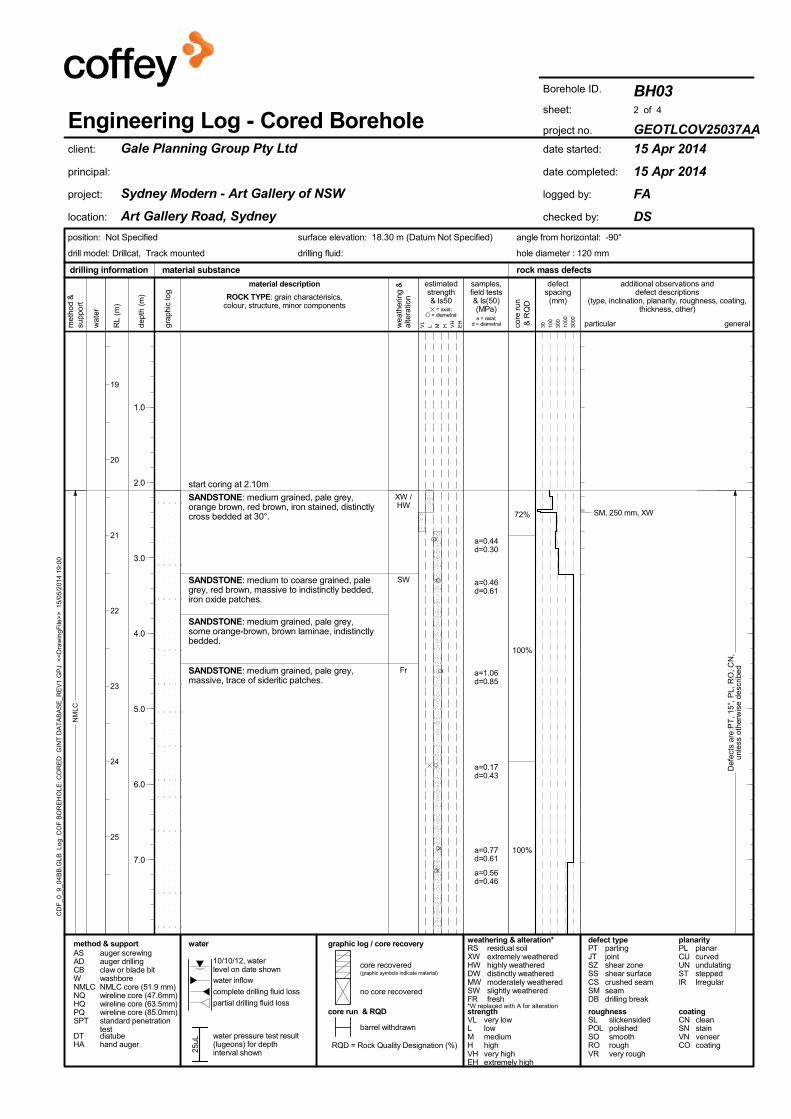
NM
LC
XW /HW
SW
Fr
SANDSTONE: medium grained, pale grey,orange brown, red brown, iron stained, distinctlycross bedded at 30°.
SANDSTONE: medium to coarse grained, palegrey, red brown, massive to indistinctly bedded,iron oxide patches.
SANDSTONE: medium grained, pale grey,some orange-brown, brown laminae, indistinctlybedded.
SANDSTONE: medium grained, pale grey,massive, trace of sideritic patches.
start coring at 2.10m
72%
100%
100%
Def
ects
are
:PT
, 15
°, P
L, R
O, C
N,
unle
ss o
ther
wis
e de
scrib
ed
SM, 250 mm, XW
a=0.44d=0.30
a=0.46d=0.61
a=1.06d=0.85
a=0.17d=0.43
a=0.77d=0.61
a=0.56d=0.46
RL
(m)
19
20
21
22
23
24
25
drilling information material substance rock mass defects
complete drilling fluid loss no core recovered
core recovered(graphic symbols indicate material)
10/10/12, waterlevel on date shown
RQD = Rock Quality Designation (%)
core run & RQD
barrel withdrawn
25uL
method & support graphic log / core recovery
partial drilling fluid loss
water inflow
water pressure test result(lugeons) for depthinterval shown
waterASADCBWNMLCNQHQPQSPT
auger screwingauger drillingclaw or blade bitwashboreNMLC core (51.9 mm)wireline core (47.6mm)wireline core (63.5mm)wireline core (85.0mm)standard penetrationtest
DTHA
diatubehand auger
grap
hic
log
defectspacing(mm)
30 100
300
1000
3000
met
hod
&su
ppor
t
wea
ther
ing
&al
tera
tionROCK TYPE: grain characterisics,
colour, structure, minor components
material description
core
run
& R
QD
BH03
GEOTLCOV25037AA
15 Apr 2014
15 Apr 2014
FA
DS
Borehole ID.
sheet:
project no.
date started:
date completed:
logged by:
checked by:
Gale Planning Group Pty Ltd
Sydney Modern - Art Gallery of NSW
Art Gallery Road, Sydney
client:
principal:
project:
location:
2 of 4
Engineering Log - Cored Borehole
angle from horizontal: -90°
hole diameter : 120 mm
position: Not Specified
drilling fluid:
surface elevation: 18.30 m (Datum Not Specified)
drill model: Drillcat, Track mounted
particular general
additional observations anddefect descriptions
(type, inclination, planarity, roughness, coating,thickness, other)
& Is50 = axial;
= diametral
VL
L M H VH
EH
estimatedstrength
dept
h (m
)
1.0
2.0
3.0
4.0
5.0
6.0
7.0
defect typePTJTSZSSCSSMDB
partingjointshear zoneshear surfacecrushed seamseamdrilling break
SLPOLSOROVR
slickensidedpolishedsmoothroughvery rough
roughness coatingCNSNVNCO
cleanstainveneercoating
planarityPLCUUNSTIR
planarcurvedundulatingsteppedIrregular
weathering & alteration*RSXWHWDWMWSWFR
residual soilextremely weatheredhighly weathereddistinctly weatheredmoderately weatheredslightly weatheredfresh
*W replaced with A for alteration
CD
F_0
_9_0
4B
B.G
LB L
og C
OF
BO
RE
HO
LE: C
OR
ED
GIN
T D
AT
AB
AS
E_R
EV
1.G
PJ
<<
Dra
win
gFile
>>
15/
05/2
014
19:0
0
a = axial;d = diametral
samples,field tests& Is(50)(MPa)
strengthVLLMHVHEH
very lowlowmediumhighvery highextremely high
wat
er

NM
LC
Fr
MW /SW
Fr
SANDSTONE: medium grained, pale grey,massive, trace of sideritic patches. (continued)
SANDSTONE: medium to coarse grained,orange brown, red brown, ironstone bands,distinctly bedded at 0 to 15°.
SANDSTONE: medium grained, pale grey,sideritic laminae, distinctly bedded at 0 to 15°.
11.85m to 12.05m: iron stained band
SANDSTONE: medium grained, pale grey,massive.
14.75m: iron stained band (50mm)
100%
87%
100%
94%
Def
ects
are
:PT
, 15
°, P
L, R
O, C
N,
unle
ss o
ther
wis
e de
scrib
ed
SM, 15°, PL, RO, Clay, 20 mm
JT, 60°, PL, RO
JT, 60°, PL, ROJT, 60°, PL, ROJT, 60°, PL, ROJT, 60°, PL, ROPT, 5°, PL, RO
PT, 10°, PL, ROhighly fractured zone (60mm)SM, 20°, PL, RO, Clay, 5 mm
SM, 5°, PL, RO, Clay, 5 mm
JT, 70°, IR, RO, Fe
PT, 10°, PL, RO, Clay
SM, 10°, PL, RO, Clay, 10 mmSM, 10°, PL, RO, Clay, 10 mm
a=0.39d=0.63
a=0.69d=0.52a=1.33d=1.13
a=0.71d=0.70
a=0.84d=1.00
a=0.75d=0.84
a=0.86d=0.80
RL
(m)
27
28
29
30
31
32
33
drilling information material substance rock mass defects
complete drilling fluid loss no core recovered
core recovered(graphic symbols indicate material)
10/10/12, waterlevel on date shown
RQD = Rock Quality Designation (%)
core run & RQD
barrel withdrawn
25uL
method & support graphic log / core recovery
partial drilling fluid loss
water inflow
water pressure test result(lugeons) for depthinterval shown
waterASADCBWNMLCNQHQPQSPT
auger screwingauger drillingclaw or blade bitwashboreNMLC core (51.9 mm)wireline core (47.6mm)wireline core (63.5mm)wireline core (85.0mm)standard penetrationtest
DTHA
diatubehand auger
grap
hic
log
defectspacing(mm)
30 100
300
1000
3000
met
hod
&su
ppor
t
wea
ther
ing
&al
tera
tionROCK TYPE: grain characterisics,
colour, structure, minor components
material description
core
run
& R
QD
BH03
GEOTLCOV25037AA
15 Apr 2014
15 Apr 2014
FA
DS
Borehole ID.
sheet:
project no.
date started:
date completed:
logged by:
checked by:
Gale Planning Group Pty Ltd
Sydney Modern - Art Gallery of NSW
Art Gallery Road, Sydney
client:
principal:
project:
location:
3 of 4
Engineering Log - Cored Borehole
angle from horizontal: -90°
hole diameter : 120 mm
position: Not Specified
drilling fluid:
surface elevation: 18.30 m (Datum Not Specified)
drill model: Drillcat, Track mounted
particular general
additional observations anddefect descriptions
(type, inclination, planarity, roughness, coating,thickness, other)
& Is50 = axial;
= diametral
VL
L M H VH
EH
estimatedstrength
dept
h (m
)
9.0
10.0
11.0
12.0
13.0
14.0
15.0
defect typePTJTSZSSCSSMDB
partingjointshear zoneshear surfacecrushed seamseamdrilling break
SLPOLSOROVR
slickensidedpolishedsmoothroughvery rough
roughness coatingCNSNVNCO
cleanstainveneercoating
planarityPLCUUNSTIR
planarcurvedundulatingsteppedIrregular
weathering & alteration*RSXWHWDWMWSWFR
residual soilextremely weatheredhighly weathereddistinctly weatheredmoderately weatheredslightly weatheredfresh
*W replaced with A for alteration
CD
F_0
_9_0
4B
B.G
LB L
og C
OF
BO
RE
HO
LE: C
OR
ED
GIN
T D
AT
AB
AS
E_R
EV
1.G
PJ
<<
Dra
win
gFile
>>
15/
05/2
014
19:0
0
a = axial;d = diametral
samples,field tests& Is(50)(MPa)
strengthVLLMHVHEH
very lowlowmediumhighvery highextremely high
wat
er

NM
LC
MW
SW
Fr
MW
16.05m to 16.15m: iron stained band
NO CORE: 0.15 m
SANDSTONE: medium grained, pale grey,massive.
SANDSTONE: medium grained, orange brown,red brown, iron stained bands, cross bedded,curved bands.
Borehole BH03 terminated at 19.95 m
94%
65%
Def
ects
are
:PT
, 15
°, P
L, R
O, C
N,
unle
ss o
ther
wis
e de
scrib
ed
SM, 5°, PL, RO, 5 mm
SM, 5°, PL, RO, Sandy clay, 2 mm
SM, 5°, PL, RO, Sandy clay, 2 mmSM, 5°, PL, RO, Sandy clay, 30 mmSM, 5°, PL, RO, Clay, 5 mmhighly fractured zone (60mm)SM, 5°, PL, RO, Clayey sand, 20 mmJT, 50°, PL, ROJT, 50°, PL, ROJT, 45°, PL, ROJT, 65°, PL, RO
JT, 70°, PL, ROPT, 20°, IR, RO
JT, 60°, PL, ROSM, 40°, PL, RO, 20 mmJT, 45°, PL, ROJT, 70°, PL, RO
a=0.62d=0.67
a=0.92d=0.86a=0.85d=0.84
a=1.03d=1.03
a=0.68d=0.60
RL
(m)
35
36
37
38
39
40
41
drilling information material substance rock mass defects
complete drilling fluid loss no core recovered
core recovered(graphic symbols indicate material)
10/10/12, waterlevel on date shown
RQD = Rock Quality Designation (%)
core run & RQD
barrel withdrawn
25uL
method & support graphic log / core recovery
partial drilling fluid loss
water inflow
water pressure test result(lugeons) for depthinterval shown
waterASADCBWNMLCNQHQPQSPT
auger screwingauger drillingclaw or blade bitwashboreNMLC core (51.9 mm)wireline core (47.6mm)wireline core (63.5mm)wireline core (85.0mm)standard penetrationtest
DTHA
diatubehand auger
grap
hic
log
defectspacing(mm)
30 100
300
1000
3000
met
hod
&su
ppor
t
wea
ther
ing
&al
tera
tionROCK TYPE: grain characterisics,
colour, structure, minor components
material description
core
run
& R
QD
BH03
GEOTLCOV25037AA
15 Apr 2014
15 Apr 2014
FA
DS
Borehole ID.
sheet:
project no.
date started:
date completed:
logged by:
checked by:
Gale Planning Group Pty Ltd
Sydney Modern - Art Gallery of NSW
Art Gallery Road, Sydney
client:
principal:
project:
location:
4 of 4
Engineering Log - Cored Borehole
angle from horizontal: -90°
hole diameter : 120 mm
position: Not Specified
drilling fluid:
surface elevation: 18.30 m (Datum Not Specified)
drill model: Drillcat, Track mounted
particular general
additional observations anddefect descriptions
(type, inclination, planarity, roughness, coating,thickness, other)
& Is50 = axial;
= diametral
VL
L M H VH
EH
estimatedstrength
dept
h (m
)
17.0
18.0
19.0
20.0
21.0
22.0
23.0
defect typePTJTSZSSCSSMDB
partingjointshear zoneshear surfacecrushed seamseamdrilling break
SLPOLSOROVR
slickensidedpolishedsmoothroughvery rough
roughness coatingCNSNVNCO
cleanstainveneercoating
planarityPLCUUNSTIR
planarcurvedundulatingsteppedIrregular
weathering & alteration*RSXWHWDWMWSWFR
residual soilextremely weatheredhighly weathereddistinctly weatheredmoderately weatheredslightly weatheredfresh
*W replaced with A for alteration
CD
F_0
_9_0
4B
B.G
LB L
og C
OF
BO
RE
HO
LE: C
OR
ED
GIN
T D
AT
AB
AS
E_R
EV
1.G
PJ
<<
Dra
win
gFile
>>
15/
05/2
014
19:0
0
a = axial;d = diametral
samples,field tests& Is(50)(MPa)
strengthVLLMHVHEH
very lowlowmediumhighvery highextremely high
wat
er

PointID : BH03 Depth Range: 2.10 - 12.00 m
FA
A4
CORE PHOTOGRAPHBH03
client:drawn
project no:
datetitle:
project:approved
original size
scale
fig no: rev:
Gale Planning Group Pty Ltd
GEOTLCOV25037AA
N.T.S.
15/05/2014
DS Sydney Modern - Art Gallery of NSWArt Gallery Road, Sydney
FIGURE 5
CD
F_0
_9_0
4B
B.G
LB G
rfcT
bl C
OF
PH
OT
O C
OR
E P
HO
TO
1 P
ER
PA
GE
GIN
T D
AT
AB
AS
E_R
EV
1.G
PJ
<<
Dra
win
gFile
>>
15/
05/2
014
18:5
3

PointID : BH03 Depth Range: 12.00 - 19.95 m
FA
A4
CORE PHOTOGRAPHBH03
client:drawn
project no:
datetitle:
project:approved
original size
scale
fig no: rev:
Gale Planning Group Pty Ltd
GEOTLCOV25037AA
N.T.S.
15/05/2014
DS Sydney Modern - Art Gallery of NSWArt Gallery Road, Sydney
FIGURE 6
CD
F_0
_9_0
4B
B.G
LB G
rfcT
bl C
OF
PH
OT
O C
OR
E P
HO
TO
1 P
ER
PA
GE
GIN
T D
AT
AB
AS
E_R
EV
1.G
PJ
<<
Dra
win
gFile
>>
15/
05/2
014
18:5
4

M
SPT15, 14, 10
N*=24
E
E
E
HA
AD
/T
CA
SIN
G
TOPSOIL: Silty SAND: medium grained, darkbrown, some plant roots.
FILL: SAND: medium grained, brown, with a traceof silt and sandstone gravel.
FILL: SAND: medium grained, dark brown andbrown, with some fine, balck gravel. Distinct odourof hydrocarbons.
SANDSTONE: medium grained, pale grey, palebrown and orange brown.
Borehole BH04 continued as cored hole
TOPSOIL
FILL
0.2m: PID = 3.40.5m: PID = 3.8
1.0m: PID = 4.8
From 1.0m to 1.5m stronghydrocarbon odour
BEDROCK
RL
(m)
23
24
25
26
27
28
29
drilling information material substance
BH04
GEOTLCOV25037AA
10 Apr 2014
11 Apr 2014
FA
DS
Borehole ID.
sheet:
project no.
date started:
date completed:
logged by:
checked by:
Gale Planning Group Pty Ltd
Sydney Modern - Art Gallery of NSW
Art Gallery Road, Sydney
client:
principal:
project:
location:
1 of 4
Engineering Log - Borehole
angle from horizontal: -90°
hole diameter : 120 mm
position: Not Specified surface elevation: 22.20 m (Datum Not Specified)
drill model: Drillcat, Track mounted
cons
iste
ncy
/re
lativ
e de
nsi
ty
grap
hic
log
moi
stur
eco
nditi
on
clas
sific
atio
nsy
mbo
l
samples &field tests
wat
er
samples & field tests consistency / relative densitysupportM mudC casing
N nil VSSFStVStHFbVLLMDDVD
very softsoftfirmstiffvery stiffhardfriablevery looseloosemedium densedensevery dense
classification symbol &soil descriptionbased on Unified
Classification System
water
water outflow
water inflow
penetration
no resistanceranging torefusal
10-Oct-12 waterlevel on date shown
method
1 2 3
BDESSU##HPNN*NcVSRHB
bulk disturbed sampledisturbed sampleenvironmental samplesplit spoon sampleundisturbed sample ##mm diameterhand penetrometer (kPa)standard penetration test (SPT)SPT - sample recoveredSPT with solid conevane shear; peak/remouded (kPa)refusalhammer bouncing
DTHA
diatubehand auger
ADASHAW
auger drilling*auger screwing*hand augerwashbore
*e.g.BTV
bit shown by suffixAD/Tblank bitTC bitV bit
met
hod
&su
ppor
t SOIL TYPE: plasticity or particle characteristic,colour, secondary and minor components
material description structure andadditional observations
1 2 3pe
netr
atio
n
dept
h (m
)
1.0
2.0
3.0
4.0
5.0
6.0
7.0
CD
F_0
_9_0
4B
B.G
LB L
og C
OF
BO
RE
HO
LE: N
ON
CO
RE
D G
INT
DA
TA
BA
SE
_RE
V1.
GP
J <
<D
raw
ingF
ile>
> 1
5/05
/201
4 18
:58
moistureDMWWpWl
drymoistwetplastic limitliquid limit
(kPa)
handpenetro-
meter
100
200
300
400

NM
LC
MW /SW
FR
MW
FR
SANDSTONE: medium grained, orange brownand pale grey, massive.
SANDSTONE: medium grained, red brown toyellow brown, ironstone bands, indistinctlybedded.
SANDSTONE: medium grained, pale grey,massive.
SANDSTONE: medium to coarse grained, redbrown, yellow brown and grey brown, pebblyquartz bands, iron stone bands, indistinctlybedded.
SANDSTONE: medium grained, pale grey,massive.
start coring at 1.55m
91%
97%
93%
Def
ects
are
:PT
, 0
- 10
°, P
L, R
O, C
N,
unle
ss o
ther
wis
e de
scrib
ed
SM, Sandy clay, 50 mm
SM, Sandy clay, 10 mm
JT, 50°, IR, RO, CNJT, 50°, IR, RO, CN
SM, 10°, PL, RO, Clay, 5 mm
SM, Sandy clay, 15 mmSM, Sandy clay, 50 mm
SM, Sandy clay, 25 mmSM, Sandy clay, 20 mmJT, 30°, IR, RO, CNSM, 20 mm, crushed
a=0.62d=0.50
a=0.34d=0.35
a=0.80d=0.68
a=0.13d=0.17
a=0.24d=0.39
a=1.38d=1.04
a=0.24d=0.27
RL
(m)
23
24
25
26
27
28
29
drilling information material substance rock mass defects
complete drilling fluid loss no core recovered
core recovered(graphic symbols indicate material)
10/10/12, waterlevel on date shown
RQD = Rock Quality Designation (%)
core run & RQD
barrel withdrawn
25uL
method & support graphic log / core recovery
partial drilling fluid loss
water inflow
water pressure test result(lugeons) for depthinterval shown
waterASADCBWNMLCNQHQPQSPT
auger screwingauger drillingclaw or blade bitwashboreNMLC core (51.9 mm)wireline core (47.6mm)wireline core (63.5mm)wireline core (85.0mm)standard penetrationtest
DTHA
diatubehand auger
grap
hic
log
defectspacing(mm)
30 100
300
1000
3000
met
hod
&su
ppor
t
wea
ther
ing
&al
tera
tionROCK TYPE: grain characterisics,
colour, structure, minor components
material description
core
run
& R
QD
BH04
GEOTLCOV25037AA
10 Apr 2014
11 Apr 2014
FA
DS
Borehole ID.
sheet:
project no.
date started:
date completed:
logged by:
checked by:
Gale Planning Group Pty Ltd
Sydney Modern - Art Gallery of NSW
Art Gallery Road, Sydney
client:
principal:
project:
location:
2 of 4
Engineering Log - Cored Borehole
angle from horizontal: -90°
hole diameter : 120 mm
position: Not Specified
drilling fluid:
surface elevation: 22.20 m (Datum Not Specified)
drill model: Drillcat, Track mounted
particular general
additional observations anddefect descriptions
(type, inclination, planarity, roughness, coating,thickness, other)
& Is50 = axial;
= diametral
VL
L M H VH
EH
estimatedstrength
dept
h (m
)
1.0
2.0
3.0
4.0
5.0
6.0
7.0
defect typePTJTSZSSCSSMDB
partingjointshear zoneshear surfacecrushed seamseamdrilling break
SLPOLSOROVR
slickensidedpolishedsmoothroughvery rough
roughness coatingCNSNVNCO
cleanstainveneercoating
planarityPLCUUNSTIR
planarcurvedundulatingsteppedIrregular
weathering & alteration*RSXWHWDWMWSWFR
residual soilextremely weatheredhighly weathereddistinctly weatheredmoderately weatheredslightly weatheredfresh
*W replaced with A for alteration
CD
F_0
_9_0
4B
B.G
LB L
og C
OF
BO
RE
HO
LE: C
OR
ED
GIN
T D
AT
AB
AS
E_R
EV
1.G
PJ
<<
Dra
win
gFile
>>
15/
05/2
014
19:0
0
a = axial;d = diametral
samples,field tests& Is(50)(MPa)
strengthVLLMHVHEH
very lowlowmediumhighvery highextremely high
wat
er

NM
LC
FR
MW /SW
XW /HW
SW
XW /HW
FR
SANDSTONE: medium grained, pale grey,massive. (continued)
SANDSTONE: medium grained, red brown,yellow brown and pale grey, ironstone bands,indistinctly bedded.
NO CORE: 0.23 m
SANDSTONE: medium grained, pale grey,sideritic laminae beds, indistinctly bedded.
NO CORE: 0.20 m
SANDSTONE: medium grained, pale grey,distinctly bedded at 0 to 10°.
93%
99%
86%
0%
86%
Def
ects
are
:PT
, 0
- 10
°, P
L, R
O, C
N,
unle
ss o
ther
wis
e de
scrib
ed
drill breaks
SM, 10°, PL, RO, Sandy clay, 8 mm
SM, Sandy clay, 50 mm
JT, 45°, IR, RO, CN
SM, 5°, IR, RO, Clayey sand, 30 mm
a=0.69d=0.62
a=0.70d=0.83
a=0.90d=0.96
a=0.49d=0.47
a=0.64d=0.67
a=1.10d=0.96
a=1.05d=1.02
a=0.71d=0.75
RL
(m)
31
32
33
34
35
36
37
drilling information material substance rock mass defects
complete drilling fluid loss no core recovered
core recovered(graphic symbols indicate material)
10/10/12, waterlevel on date shown
RQD = Rock Quality Designation (%)
core run & RQD
barrel withdrawn
25uL
method & support graphic log / core recovery
partial drilling fluid loss
water inflow
water pressure test result(lugeons) for depthinterval shown
waterASADCBWNMLCNQHQPQSPT
auger screwingauger drillingclaw or blade bitwashboreNMLC core (51.9 mm)wireline core (47.6mm)wireline core (63.5mm)wireline core (85.0mm)standard penetrationtest
DTHA
diatubehand auger
grap
hic
log
defectspacing(mm)
30 100
300
1000
3000
met
hod
&su
ppor
t
wea
ther
ing
&al
tera
tionROCK TYPE: grain characterisics,
colour, structure, minor components
material description
core
run
& R
QD
BH04
GEOTLCOV25037AA
10 Apr 2014
11 Apr 2014
FA
DS
Borehole ID.
sheet:
project no.
date started:
date completed:
logged by:
checked by:
Gale Planning Group Pty Ltd
Sydney Modern - Art Gallery of NSW
Art Gallery Road, Sydney
client:
principal:
project:
location:
3 of 4
Engineering Log - Cored Borehole
angle from horizontal: -90°
hole diameter : 120 mm
position: Not Specified
drilling fluid:
surface elevation: 22.20 m (Datum Not Specified)
drill model: Drillcat, Track mounted
particular general
additional observations anddefect descriptions
(type, inclination, planarity, roughness, coating,thickness, other)
& Is50 = axial;
= diametral
VL
L M H VH
EH
estimatedstrength
dept
h (m
)
9.0
10.0
11.0
12.0
13.0
14.0
15.0
defect typePTJTSZSSCSSMDB
partingjointshear zoneshear surfacecrushed seamseamdrilling break
SLPOLSOROVR
slickensidedpolishedsmoothroughvery rough
roughness coatingCNSNVNCO
cleanstainveneercoating
planarityPLCUUNSTIR
planarcurvedundulatingsteppedIrregular
weathering & alteration*RSXWHWDWMWSWFR
residual soilextremely weatheredhighly weathereddistinctly weatheredmoderately weatheredslightly weatheredfresh
*W replaced with A for alteration
CD
F_0
_9_0
4B
B.G
LB L
og C
OF
BO
RE
HO
LE: C
OR
ED
GIN
T D
AT
AB
AS
E_R
EV
1.G
PJ
<<
Dra
win
gFile
>>
15/
05/2
014
19:0
0
a = axial;d = diametral
samples,field tests& Is(50)(MPa)
strengthVLLMHVHEH
very lowlowmediumhighvery highextremely high
wat
er11
/04/
14

NM
LC
FR
SW /FR
SANDSTONE: medium grained, pale grey,distinctly bedded at 0 to 10°. (continued)
SANDSTONE: medium grained, red brown,yellow brown and pale grey, distinctly bedded at0 to 10°.17.1 to 17.4 m: iron stained, curved bands
SANDSTONE: medium grained, pale grey,orange brown, some iron staining, sideriticlaminae, indistinctly bedded.
Borehole BH04 terminated at 20.00 m
86%
91% Def
ects
are
:PT
, 0
- 10
°, P
L, R
O, C
N,
unle
ss o
ther
wis
e de
scrib
ed
JT, 65°, IR, RO, CN
SM, 5°, PL, RO, Clayey sand, 5 mm
PT, 10°, PL, RO, CO
SM, 5°, PL, RO, Sandy clay, 8 mm
SM, 5°, PL, RO, Clay, 10 mm
SM, 30 mmSM, 5°, PL, RO, Sandy clay, 3 mmSM, 10°, PL, RO, Clay, 15 mmSM, 40°, PL, RO, Clay, 30 mmSM, 30°, PL, RO, Clay, 20 mmSM, 40°, PL, RO, Clay, 8 mmSM, 15°, PL, RO, Clay, 8 mmSM, 40°, PL, RO, Clay, 8 mmSM, 30°, PL, RO, Clay, 15 mmSM, 10°, PL, RO, Clayey sand, 15 mm
a=0.67d=0.96
a=0.64d=0.69
a=0.59d=0.54
a=0.19d=0.62
RL
(m)
39
40
41
42
43
44
45
drilling information material substance rock mass defects
complete drilling fluid loss no core recovered
core recovered(graphic symbols indicate material)
10/10/12, waterlevel on date shown
RQD = Rock Quality Designation (%)
core run & RQD
barrel withdrawn
25uL
method & support graphic log / core recovery
partial drilling fluid loss
water inflow
water pressure test result(lugeons) for depthinterval shown
waterASADCBWNMLCNQHQPQSPT
auger screwingauger drillingclaw or blade bitwashboreNMLC core (51.9 mm)wireline core (47.6mm)wireline core (63.5mm)wireline core (85.0mm)standard penetrationtest
DTHA
diatubehand auger
grap
hic
log
defectspacing(mm)
30 100
300
1000
3000
met
hod
&su
ppor
t
wea
ther
ing
&al
tera
tionROCK TYPE: grain characterisics,
colour, structure, minor components
material description
core
run
& R
QD
BH04
GEOTLCOV25037AA
10 Apr 2014
11 Apr 2014
FA
DS
Borehole ID.
sheet:
project no.
date started:
date completed:
logged by:
checked by:
Gale Planning Group Pty Ltd
Sydney Modern - Art Gallery of NSW
Art Gallery Road, Sydney
client:
principal:
project:
location:
4 of 4
Engineering Log - Cored Borehole
angle from horizontal: -90°
hole diameter : 120 mm
position: Not Specified
drilling fluid:
surface elevation: 22.20 m (Datum Not Specified)
drill model: Drillcat, Track mounted
particular general
additional observations anddefect descriptions
(type, inclination, planarity, roughness, coating,thickness, other)
& Is50 = axial;
= diametral
VL
L M H VH
EH
estimatedstrength
dept
h (m
)
17.0
18.0
19.0
20.0
21.0
22.0
23.0
defect typePTJTSZSSCSSMDB
partingjointshear zoneshear surfacecrushed seamseamdrilling break
SLPOLSOROVR
slickensidedpolishedsmoothroughvery rough
roughness coatingCNSNVNCO
cleanstainveneercoating
planarityPLCUUNSTIR
planarcurvedundulatingsteppedIrregular
weathering & alteration*RSXWHWDWMWSWFR
residual soilextremely weatheredhighly weathereddistinctly weatheredmoderately weatheredslightly weatheredfresh
*W replaced with A for alteration
CD
F_0
_9_0
4B
B.G
LB L
og C
OF
BO
RE
HO
LE: C
OR
ED
GIN
T D
AT
AB
AS
E_R
EV
1.G
PJ
<<
Dra
win
gFile
>>
15/
05/2
014
19:0
0
a = axial;d = diametral
samples,field tests& Is(50)(MPa)
strengthVLLMHVHEH
very lowlowmediumhighvery highextremely high
wat
er

PointID : BH04 Depth Range: 1.55 - 11.00 m
FA
A4
CORE PHOTOGRAPHBH04
client:drawn
project no:
datetitle:
project:approved
original size
scale
fig no: rev:
Gale Planning Group Pty Ltd
GEOTLCOV25037AA
N.T.S.
15/05/2014
DS Sydney Modern - Art Gallery of NSWArt Gallery Road, Sydney
FIGURE 7
CD
F_0
_9_0
4B
B.G
LB G
rfcT
bl C
OF
PH
OT
O C
OR
E P
HO
TO
1 P
ER
PA
GE
GIN
T D
AT
AB
AS
E_R
EV
1.G
PJ
<<
Dra
win
gFile
>>
15/
05/2
014
18:5
4

PointID : BH04 Depth Range: 11.00 - 20.00 m
FA
A4
CORE PHOTOGRAPHBH04
client:drawn
project no:
datetitle:
project:approved
original size
scale
fig no: rev:
Gale Planning Group Pty Ltd
GEOTLCOV25037AA
N.T.S.
15/05/2014
DS Sydney Modern - Art Gallery of NSWArt Gallery Road, Sydney
FIGURE 8
CD
F_0
_9_0
4B
B.G
LB G
rfcT
bl C
OF
PH
OT
O C
OR
E P
HO
TO
1 P
ER
PA
GE
GIN
T D
AT
AB
AS
E_R
EV
1.G
PJ
<<
Dra
win
gFile
>>
15/
05/2
014
18:5
4

M
MSPT14,
10/70mmN=R
E
E
DT
AD
/TN
MLC
CA
SIN
G
CONCRETE: 0.3m.
FILL: SAND: fine grained, brown, pale brown,trace of fine sandstone gravel.
from 0.7m trace of concrete gravel
CONCRETE: 0.1m.
NO CORE: 0.45m (1.00-1.45) NO CORE
FILL: SAND: medium grained, pale brown, orangebrown, with sandstone gravels, concrete fragments,glass fragments.from 1.7m to 1.85m fine to medium gravel, darkgrey, pale grey, orange brownfrom 1.85m to 2.0m concrete slab (0.15m)
Borehole BH05 terminated at 2.0 m
CONCRETE SLAB
FILL
0.3m: PID = 3.90.5m: PID = 4.3
CONCRETE SLAB
FILL
HOLE TERMINATED AT 2.0m.ENCOUNTERED CONCRETESLAB, POSSIBLEUNDERGROUND CONCRETESTRUCTURE
RL
(m)
16
17
18
19
20
21
22
drilling information material substance
BH05
GEOTLCOV25037AA
22 Apr 2014
22 Apr 2014
FA
DS
Borehole ID.
sheet:
project no.
date started:
date completed:
logged by:
checked by:
Gale Planning Group Pty Ltd
Sydney Modern - Art Gallery of NSW
Art Gallery Road, Sydney
client:
principal:
project:
location:
1 of 1
Engineering Log - Borehole
angle from horizontal: -90°
hole diameter : 120 mm
position: Not Specified surface elevation: 15.20 m (Datum Not Specified)
drill model: XC Drill, Track mounted
cons
iste
ncy
/re
lativ
e de
nsi
ty
grap
hic
log
moi
stur
eco
nditi
on
clas
sific
atio
nsy
mbo
l
samples &field tests
wat
er
samples & field tests consistency / relative densitysupportM mudC casing
N nil VSSFStVStHFbVLLMDDVD
very softsoftfirmstiffvery stiffhardfriablevery looseloosemedium densedensevery dense
classification symbol &soil descriptionbased on Unified
Classification System
water
water outflow
water inflow
penetration
no resistanceranging torefusal
10-Oct-12 waterlevel on date shown
method
1 2 3
BDESSU##HPNN*NcVSRHB
bulk disturbed sampledisturbed sampleenvironmental samplesplit spoon sampleundisturbed sample ##mm diameterhand penetrometer (kPa)standard penetration test (SPT)SPT - sample recoveredSPT with solid conevane shear; peak/remouded (kPa)refusalhammer bouncing
DTHA
diatubehand auger
ADASHAW
auger drilling*auger screwing*hand augerwashbore
*e.g.BTV
bit shown by suffixAD/Tblank bitTC bitV bit
met
hod
&su
ppor
t SOIL TYPE: plasticity or particle characteristic,colour, secondary and minor components
material description structure andadditional observations
1 2 3pe
netr
atio
n
dept
h (m
)
1.0
2.0
3.0
4.0
5.0
6.0
7.0
CD
F_0
_9_0
4B
B.G
LB L
og C
OF
BO
RE
HO
LE: N
ON
CO
RE
D G
INT
DA
TA
BA
SE
_RE
V1.
GP
J <
<D
raw
ingF
ile>
> 1
5/05
/201
4 18
:58
moistureDMWWpWl
drymoistwetplastic limitliquid limit
(kPa)
handpenetro-
meter
100
200
300
400

M
SPT8/90mm
N*=R
E
E
E
HA
CA
SIN
G
TOPSOIL: Silty SAND: medium grained, darkbrown, with some rootlets.
FILL: Silty SAND: medium to coarse grained, darkbrown, with some tile fragments and fine gravel.
FILL: SAND: fine to medium grained, brown, withtrace of fine grained gravel..
SANDSTONE: medium grained, pale brown,orange brown, extremely weathered, estimated lowstrength.
Borehole BH06 continued as cored hole
TOPSOIL
FILL
0.2m: PID = 4.90.5m: PID = 4.3
BEDROCK
1.0m: PID = 4.6
RL
(m)
25
26
27
28
29
30
31
drilling information material substance
BH06
GEOTLCOV25037AA
08 Apr 2014
09 Apr 2014
FA
DS
Borehole ID.
sheet:
project no.
date started:
date completed:
logged by:
checked by:
Gale Planning Group Pty Ltd
Sydney Modern - Art Gallery of NSW
Art Gallery Road, Sydney
client:
principal:
project:
location:
1 of 4
Engineering Log - Borehole
angle from horizontal: -90°
hole diameter : 120 mm
position: Not Specified surface elevation: 24.30 m (Datum Not Specified)
drill model: Drillcat, Track mounted
cons
iste
ncy
/re
lativ
e de
nsi
ty
grap
hic
log
moi
stur
eco
nditi
on
clas
sific
atio
nsy
mbo
l
samples &field tests
wat
er
samples & field tests consistency / relative densitysupportM mudC casing
N nil VSSFStVStHFbVLLMDDVD
very softsoftfirmstiffvery stiffhardfriablevery looseloosemedium densedensevery dense
classification symbol &soil descriptionbased on Unified
Classification System
water
water outflow
water inflow
penetration
no resistanceranging torefusal
10-Oct-12 waterlevel on date shown
method
1 2 3
BDESSU##HPNN*NcVSRHB
bulk disturbed sampledisturbed sampleenvironmental samplesplit spoon sampleundisturbed sample ##mm diameterhand penetrometer (kPa)standard penetration test (SPT)SPT - sample recoveredSPT with solid conevane shear; peak/remouded (kPa)refusalhammer bouncing
DTHA
diatubehand auger
ADASHAW
auger drilling*auger screwing*hand augerwashbore
*e.g.BTV
bit shown by suffixAD/Tblank bitTC bitV bit
met
hod
&su
ppor
t SOIL TYPE: plasticity or particle characteristic,colour, secondary and minor components
material description structure andadditional observations
1 2 3pe
netr
atio
n
dept
h (m
)
1.0
2.0
3.0
4.0
5.0
6.0
7.0
CD
F_0
_9_0
4B
B.G
LB L
og C
OF
BO
RE
HO
LE: N
ON
CO
RE
D G
INT
DA
TA
BA
SE
_RE
V1.
GP
J <
<D
raw
ingF
ile>
> 1
5/05
/201
4 18
:58
moistureDMWWpWl
drymoistwetplastic limitliquid limit
(kPa)
handpenetro-
meter
100
200
300
400

NM
LC
MW /SW
SANDSTONE: medium to coarse grained,brown, dark brown, pebbly bands, ironstonebands, indistinctly bedded at 0 to 40°.from 1.5m to 1.7m pale grey
SANDSTONE: medium grained, red brown andyellow brown, some ironstone bands, indistinctlybedded.
from 4.5m to 4.75m fine grained, pale grey
SANDSTONE: medium grained, red brown toorange brown, distinctly bedded at 0.
start coring at 1.10m
97%
80%
96%
Def
ects
are
:PT
, 0
- 10
°, P
L, R
O, C
N,
side
rite
lam
inae
unle
ss o
ther
wis
e de
scrib
ed
SM, Sandy clay, 40 mm, XW
PT, 0 - 10°, PL, RO, CNPT, 0 - 10°, PL, RO, CN
SM, Sandy clay, 80 mm, XW
SM, 5°, PL, RO, Sandy clay, 10 mm
SM, 0°, PL, RO, Sandy clay, 20 mm
SM, 0°, PL, RO, Sandy clay, 30 mm
JT, 40°, IR, RO, CO, carbonaceouslaminae
pebbly band
SM, 0°, PL, RO, Sandy clay, 10 mm
a=0.60d=1.07
a=0.66d=0.83
a=0.68d=0.70
a=0.12d=0.13
a=0.86d=0.60
a=0.73d=0.68
a=0.76d=0.56
RL
(m)
25
26
27
28
29
30
31
drilling information material substance rock mass defects
complete drilling fluid loss no core recovered
core recovered(graphic symbols indicate material)
10/10/12, waterlevel on date shown
RQD = Rock Quality Designation (%)
core run & RQD
barrel withdrawn
25uL
method & support graphic log / core recovery
partial drilling fluid loss
water inflow
water pressure test result(lugeons) for depthinterval shown
waterASADCBWNMLCNQHQPQSPT
auger screwingauger drillingclaw or blade bitwashboreNMLC core (51.9 mm)wireline core (47.6mm)wireline core (63.5mm)wireline core (85.0mm)standard penetrationtest
DTHA
diatubehand auger
grap
hic
log
defectspacing(mm)
30 100
300
1000
3000
met
hod
&su
ppor
t
wea
ther
ing
&al
tera
tionROCK TYPE: grain characterisics,
colour, structure, minor components
material description
core
run
& R
QD
BH06
GEOTLCOV25037AA
08 Apr 2014
09 Apr 2014
FA
DS
Borehole ID.
sheet:
project no.
date started:
date completed:
logged by:
checked by:
Gale Planning Group Pty Ltd
Sydney Modern - Art Gallery of NSW
Art Gallery Road, Sydney
client:
principal:
project:
location:
2 of 4
Engineering Log - Cored Borehole
angle from horizontal: -90°
hole diameter : 120 mm
position: Not Specified
drilling fluid:
surface elevation: 24.30 m (Datum Not Specified)
drill model: Drillcat, Track mounted
particular general
additional observations anddefect descriptions
(type, inclination, planarity, roughness, coating,thickness, other)
& Is50 = axial;
= diametral
VL
L M H VH
EH
estimatedstrength
dept
h (m
)
1.0
2.0
3.0
4.0
5.0
6.0
7.0
defect typePTJTSZSSCSSMDB
partingjointshear zoneshear surfacecrushed seamseamdrilling break
SLPOLSOROVR
slickensidedpolishedsmoothroughvery rough
roughness coatingCNSNVNCO
cleanstainveneercoating
planarityPLCUUNSTIR
planarcurvedundulatingsteppedIrregular
weathering & alteration*RSXWHWDWMWSWFR
residual soilextremely weatheredhighly weathereddistinctly weatheredmoderately weatheredslightly weatheredfresh
*W replaced with A for alteration
CD
F_0
_9_0
4B
B.G
LB L
og C
OF
BO
RE
HO
LE: C
OR
ED
GIN
T D
AT
AB
AS
E_R
EV
1.G
PJ
<<
Dra
win
gFile
>>
15/
05/2
014
19:0
0
a = axial;d = diametral
samples,field tests& Is(50)(MPa)
strengthVLLMHVHEH
very lowlowmediumhighvery highextremely high
wat
er

NM
LC
MW /SW
FR /SW
FR
SANDSTONE: medium grained, pale grey tored brown, siderite laminae, indistinctly todistinctly bedded at 0 to 20°.
SANDSTONE: medium grained, pale grey,trace of siderite laminae, indistinctly bedded.11.22 m: trace of shale clasts (10mm)11.32 m: trace of shale clasts (10mm)
11.93 m: shale band 40mm
SANDSTONE: medium grained, pale grey, redbrown, siderite laminae, indistinctly bedded.
SANDSTONE: medium grained, pale grey,trace of siderite patches, indistinctly bedded.
14.4 m: trace of shale clasts (10mm)14.5 m: trace of shale clasts (10mm)
96%
91%
96%
93%
Def
ects
are
:PT
, 0
- 10
°, P
L, R
O, C
N,
side
rite
lam
inae
unle
ss o
ther
wis
e de
scrib
ed
SM, Sandy clay, 20 mm, XW
SM, Sandy clay, 10 mm, XW
SM, 5 mm, XW
JT, 45°, PL, RO, carbonaceouslaminaehighly fractured zoneSM, 0°, PL, RO, Clayey sand, 10 mm
SM, 0 - 5°, PL, RO, Sandy clay, 10 mm
SM, 0 - 5°, PL, RO, Sandy clay, 40 mm
SM, 5°, PL, RO, Sandy clay, 10 mm
SM, 5°, PL, RO, Sandy clay, 20 mm
SM, 5°, PL, RO, Gravelly sand, 10 mm
SM, 5°, PL, RO, Sandy clay, 10 mm
a=0.32d=0.44
a=1.66d=1.47
a=0.83d=0.91
a=0.49d=0.54
a=0.91d=0.40
a=0.82d=0.88
a=0.95d=0.78
a=0.45d=0.85
RL
(m)
33
34
35
36
37
38
39
drilling information material substance rock mass defects
complete drilling fluid loss no core recovered
core recovered(graphic symbols indicate material)
10/10/12, waterlevel on date shown
RQD = Rock Quality Designation (%)
core run & RQD
barrel withdrawn
25uL
method & support graphic log / core recovery
partial drilling fluid loss
water inflow
water pressure test result(lugeons) for depthinterval shown
waterASADCBWNMLCNQHQPQSPT
auger screwingauger drillingclaw or blade bitwashboreNMLC core (51.9 mm)wireline core (47.6mm)wireline core (63.5mm)wireline core (85.0mm)standard penetrationtest
DTHA
diatubehand auger
grap
hic
log
defectspacing(mm)
30 100
300
1000
3000
met
hod
&su
ppor
t
wea
ther
ing
&al
tera
tionROCK TYPE: grain characterisics,
colour, structure, minor components
material description
core
run
& R
QD
BH06
GEOTLCOV25037AA
08 Apr 2014
09 Apr 2014
FA
DS
Borehole ID.
sheet:
project no.
date started:
date completed:
logged by:
checked by:
Gale Planning Group Pty Ltd
Sydney Modern - Art Gallery of NSW
Art Gallery Road, Sydney
client:
principal:
project:
location:
3 of 4
Engineering Log - Cored Borehole
angle from horizontal: -90°
hole diameter : 120 mm
position: Not Specified
drilling fluid:
surface elevation: 24.30 m (Datum Not Specified)
drill model: Drillcat, Track mounted
particular general
additional observations anddefect descriptions
(type, inclination, planarity, roughness, coating,thickness, other)
& Is50 = axial;
= diametral
VL
L M H VH
EH
estimatedstrength
dept
h (m
)
9.0
10.0
11.0
12.0
13.0
14.0
15.0
defect typePTJTSZSSCSSMDB
partingjointshear zoneshear surfacecrushed seamseamdrilling break
SLPOLSOROVR
slickensidedpolishedsmoothroughvery rough
roughness coatingCNSNVNCO
cleanstainveneercoating
planarityPLCUUNSTIR
planarcurvedundulatingsteppedIrregular
weathering & alteration*RSXWHWDWMWSWFR
residual soilextremely weatheredhighly weathereddistinctly weatheredmoderately weatheredslightly weatheredfresh
*W replaced with A for alteration
CD
F_0
_9_0
4B
B.G
LB L
og C
OF
BO
RE
HO
LE: C
OR
ED
GIN
T D
AT
AB
AS
E_R
EV
1.G
PJ
<<
Dra
win
gFile
>>
15/
05/2
014
19:0
0
a = axial;d = diametral
samples,field tests& Is(50)(MPa)
strengthVLLMHVHEH
very lowlowmediumhighvery highextremely high
wat
er09
/04/
14

NM
LC
FR
MW /SW
FR
SANDSTONE: medium grained, pale grey,trace of siderite patches, indistinctly bedded.(continued)
SANDSTONE: medium grained, pale grey,orange brown, iron stained, distinctly bedded at 0to 20°.
SANDSTONE: medium grained, pale grey,massive, trace of siderite patches.
Borehole BH06 terminated at 20.20 m
93%
98%
Def
ects
are
:PT
, 0
- 10
°, P
L, R
O, C
N,
side
rite
lam
inae
unle
ss o
ther
wis
e de
scrib
ed
JT, 90°, IR, RO, CN
PT, 0°, PL, RO, CO, coaly lenticles
SM, 5°, PL, RO, Clay, 5 mmSM, 0°, PL, RO, Clay, 40 mm
SM, 0°, PL, RO, Clay, 5 mm
a=1.30d=1.20
a=2.20d=1.61
a=0.84d=1.24
a=2.52d=1.22
a=1.17d=1.27
RL
(m)
41
42
43
44
45
46
47
drilling information material substance rock mass defects
complete drilling fluid loss no core recovered
core recovered(graphic symbols indicate material)
10/10/12, waterlevel on date shown
RQD = Rock Quality Designation (%)
core run & RQD
barrel withdrawn
25uL
method & support graphic log / core recovery
partial drilling fluid loss
water inflow
water pressure test result(lugeons) for depthinterval shown
waterASADCBWNMLCNQHQPQSPT
auger screwingauger drillingclaw or blade bitwashboreNMLC core (51.9 mm)wireline core (47.6mm)wireline core (63.5mm)wireline core (85.0mm)standard penetrationtest
DTHA
diatubehand auger
grap
hic
log
defectspacing(mm)
30 100
300
1000
3000
met
hod
&su
ppor
t
wea
ther
ing
&al
tera
tionROCK TYPE: grain characterisics,
colour, structure, minor components
material description
core
run
& R
QD
BH06
GEOTLCOV25037AA
08 Apr 2014
09 Apr 2014
FA
DS
Borehole ID.
sheet:
project no.
date started:
date completed:
logged by:
checked by:
Gale Planning Group Pty Ltd
Sydney Modern - Art Gallery of NSW
Art Gallery Road, Sydney
client:
principal:
project:
location:
4 of 4
Engineering Log - Cored Borehole
angle from horizontal: -90°
hole diameter : 120 mm
position: Not Specified
drilling fluid:
surface elevation: 24.30 m (Datum Not Specified)
drill model: Drillcat, Track mounted
particular general
additional observations anddefect descriptions
(type, inclination, planarity, roughness, coating,thickness, other)
& Is50 = axial;
= diametral
VL
L M H VH
EH
estimatedstrength
dept
h (m
)
17.0
18.0
19.0
20.0
21.0
22.0
23.0
defect typePTJTSZSSCSSMDB
partingjointshear zoneshear surfacecrushed seamseamdrilling break
SLPOLSOROVR
slickensidedpolishedsmoothroughvery rough
roughness coatingCNSNVNCO
cleanstainveneercoating
planarityPLCUUNSTIR
planarcurvedundulatingsteppedIrregular
weathering & alteration*RSXWHWDWMWSWFR
residual soilextremely weatheredhighly weathereddistinctly weatheredmoderately weatheredslightly weatheredfresh
*W replaced with A for alteration
CD
F_0
_9_0
4B
B.G
LB L
og C
OF
BO
RE
HO
LE: C
OR
ED
GIN
T D
AT
AB
AS
E_R
EV
1.G
PJ
<<
Dra
win
gFile
>>
15/
05/2
014
19:0
0
a = axial;d = diametral
samples,field tests& Is(50)(MPa)
strengthVLLMHVHEH
very lowlowmediumhighvery highextremely high
wat
er

PointID : BH06 Depth Range: 1.10 - 11.00 m
FA
A4
CORE PHOTOGRAPHBH06
client:drawn
project no:
datetitle:
project:approved
original size
scale
fig no: rev:
Gale Planning Group Pty Ltd
GEOTLCOV25037AA
N.T.S.
15/05/2014
DS Sydney Modern - Art Gallery of NSWArt Gallery Road, Sydney
FIGURE 9
CD
F_0
_9_0
4B
B.G
LB G
rfcT
bl C
OF
PH
OT
O C
OR
E P
HO
TO
1 P
ER
PA
GE
GIN
T D
AT
AB
AS
E_R
EV
1.G
PJ
<<
Dra
win
gFile
>>
15/
05/2
014
18:5
4

PointID : BH06 Depth Range: 11.00 - 20.20 m
FA
A4
CORE PHOTOGRAPHBH06
client:drawn
project no:
datetitle:
project:approved
original size
scale
fig no: rev:
Gale Planning Group Pty Ltd
GEOTLCOV25037AA
N.T.S.
15/05/2014
DS Sydney Modern - Art Gallery of NSWArt Gallery Road, Sydney
FIGURE 10
CD
F_0
_9_0
4B
B.G
LB G
rfcT
bl C
OF
PH
OT
O C
OR
E P
HO
TO
1 P
ER
PA
GE
GIN
T D
AT
AB
AS
E_R
EV
1.G
PJ
<<
Dra
win
gFile
>>
15/
05/2
014
18:5
4

ME
E
E
HA
AD
/T
CA
SIN
G
TOPSOIL: Silty SAND: medium grained, darkbrown, with some rootlets.
FILL: Silty SAND: medium grained, dark brown,with some tile and brick fragments.
SANDSTONE: medium grained, pale brown,orange brown, extremely weathered, estimated lowstrength.
Borehole BH07 continued as cored hole
TOPSOIL
FILL
0.2m: PID = 2.20.5m: PID = 2.1
1.0m: PID = 3.2
BEDROCK
RL
(m)
25
26
27
28
29
30
31
drilling information material substance
BH07
GEOTLCOV25037AA
09 Apr 2014
09 Apr 2014
FA
DS
Borehole ID.
sheet:
project no.
date started:
date completed:
logged by:
checked by:
Gale Planning Group Pty Ltd
Sydney Modern - Art Gallery of NSW
Art Gallery Road, Sydney
client:
principal:
project:
location:
1 of 4
Engineering Log - Borehole
angle from horizontal: -90°
hole diameter : 120 mm
position: Not Specified surface elevation: 24.50 m (Datum Not Specified)
drill model: Drillcat, Track mounted
cons
iste
ncy
/re
lativ
e de
nsi
ty
grap
hic
log
moi
stur
eco
nditi
on
clas
sific
atio
nsy
mbo
l
samples &field tests
wat
er
samples & field tests consistency / relative densitysupportM mudC casing
N nil VSSFStVStHFbVLLMDDVD
very softsoftfirmstiffvery stiffhardfriablevery looseloosemedium densedensevery dense
classification symbol &soil descriptionbased on Unified
Classification System
water
water outflow
water inflow
penetration
no resistanceranging torefusal
10-Oct-12 waterlevel on date shown
method
1 2 3
BDESSU##HPNN*NcVSRHB
bulk disturbed sampledisturbed sampleenvironmental samplesplit spoon sampleundisturbed sample ##mm diameterhand penetrometer (kPa)standard penetration test (SPT)SPT - sample recoveredSPT with solid conevane shear; peak/remouded (kPa)refusalhammer bouncing
DTHA
diatubehand auger
ADASHAW
auger drilling*auger screwing*hand augerwashbore
*e.g.BTV
bit shown by suffixAD/Tblank bitTC bitV bit
met
hod
&su
ppor
t SOIL TYPE: plasticity or particle characteristic,colour, secondary and minor components
material description structure andadditional observations
1 2 3pe
netr
atio
n
dept
h (m
)
1.0
2.0
3.0
4.0
5.0
6.0
7.0
CD
F_0
_9_0
4B
B.G
LB L
og C
OF
BO
RE
HO
LE: N
ON
CO
RE
D G
INT
DA
TA
BA
SE
_RE
V1.
GP
J <
<D
raw
ingF
ile>
> 1
5/05
/201
4 18
:58
moistureDMWWpWl
drymoistwetplastic limitliquid limit
(kPa)
handpenetro-
meter
100
200
300
400

NM
LC
XW /HW
MW
SW
FR
FR
MW
FR
SANDSTONE: medium grained, red brown,yellow brown, pale grey, iron stained, massive,trace of siderite patches.
2 to 2.15 m: plant root
SANDSTONE: medium grained, red brown, ironstained, distinctly bedded at 0 to 20°.
4.3 m: becoming pale grey to orange brown
SANDSTONE: medium grained, pale grey,trace of siderite patches, indistinctly bedded.
NO CORE: 0.05 m
SANDSTONE: medium grained, pale grey,trace of siderite patches, indistinctly bedded.
SANDSTONE: medium grained, red brown,yellow brown, iron stained, distinctly bedded at 0to 20°, some curved bedding.
SANDSTONE: medium grained, pale grey,trace of siderite patches, indistinctly bedded.
start coring at 1.15m
67%
51%
89%
Def
ects
are
:PT
, 0
- 10
°, P
L, R
O, C
N,
unle
ss o
ther
wis
e de
scrib
ed
vertical plant root development
PT, 0 - 10°, PL, RO, CO, sideritelaminaeJT, 95°, PL, RO, CO, siderite
SM, 10°, PL, RO, Sandy clay, 100 mmJT, 45°, PL, RO, CO, siderite
PT, 10°, PL, RO, CO, siderite
SM, 5°, PL, RO, Sandy clay, 15 mm
a=0.24d=0.29
a=0.61d=0.47
a=0.07d=0.14
a=0.43d=0.30
a=0.56d=0.56
a=0.60d=0.58
RL
(m)
25
26
27
28
29
30
31
drilling information material substance rock mass defects
complete drilling fluid loss no core recovered
core recovered(graphic symbols indicate material)
10/10/12, waterlevel on date shown
RQD = Rock Quality Designation (%)
core run & RQD
barrel withdrawn
25uL
method & support graphic log / core recovery
partial drilling fluid loss
water inflow
water pressure test result(lugeons) for depthinterval shown
waterASADCBWNMLCNQHQPQSPT
auger screwingauger drillingclaw or blade bitwashboreNMLC core (51.9 mm)wireline core (47.6mm)wireline core (63.5mm)wireline core (85.0mm)standard penetrationtest
DTHA
diatubehand auger
grap
hic
log
defectspacing(mm)
30 100
300
1000
3000
met
hod
&su
ppor
t
wea
ther
ing
&al
tera
tionROCK TYPE: grain characterisics,
colour, structure, minor components
material description
core
run
& R
QD
BH07
GEOTLCOV25037AA
09 Apr 2014
09 Apr 2014
FA
DS
Borehole ID.
sheet:
project no.
date started:
date completed:
logged by:
checked by:
Gale Planning Group Pty Ltd
Sydney Modern - Art Gallery of NSW
Art Gallery Road, Sydney
client:
principal:
project:
location:
2 of 4
Engineering Log - Cored Borehole
angle from horizontal: -90°
hole diameter : 120 mm
position: Not Specified
drilling fluid:
surface elevation: 24.50 m (Datum Not Specified)
drill model: Drillcat, Track mounted
particular general
additional observations anddefect descriptions
(type, inclination, planarity, roughness, coating,thickness, other)
& Is50 = axial;
= diametral
VL
L M H VH
EH
estimatedstrength
dept
h (m
)
1.0
2.0
3.0
4.0
5.0
6.0
7.0
defect typePTJTSZSSCSSMDB
partingjointshear zoneshear surfacecrushed seamseamdrilling break
SLPOLSOROVR
slickensidedpolishedsmoothroughvery rough
roughness coatingCNSNVNCO
cleanstainveneercoating
planarityPLCUUNSTIR
planarcurvedundulatingsteppedIrregular
weathering & alteration*RSXWHWDWMWSWFR
residual soilextremely weatheredhighly weathereddistinctly weatheredmoderately weatheredslightly weatheredfresh
*W replaced with A for alteration
CD
F_0
_9_0
4B
B.G
LB L
og C
OF
BO
RE
HO
LE: C
OR
ED
GIN
T D
AT
AB
AS
E_R
EV
1.G
PJ
<<
Dra
win
gFile
>>
15/
05/2
014
19:0
0
a = axial;d = diametral
samples,field tests& Is(50)(MPa)
strengthVLLMHVHEH
very lowlowmediumhighvery highextremely high
wat
er

NM
LC
FR
FR /SW
FR
7.92 m: carbonaceous laminaeSANDSTONE: medium grained, pale grey,trace of siderite patches, indistinctly bedded.(continued)
11.08 m: shale band 8mm
SANDSTONE: medium to coarse grained, palegrey, red brown, orange brown, pebbly bands(quartz), indistinctly bedded.11.58 m: shale band 15mm
13 to 13.2 m: ironstone laminae, thinly bedded
SANDSTONE: medium grained, pale grey,trace of ironstone laminae, indistinctly bedded.
13.75 m: trace of shale clast (10mm)
89%
94%
Def
ects
are
:PT
, 0
- 10
°, P
L, R
O, C
N,
unle
ss o
ther
wis
e de
scrib
ed
SM, 10°, PL, RO, Clay, 30 mmSM, 10°, PL, RO, Clay, 10 mm
SM, 10°, PL, RO, Clay, 10 mm
SM, 5°, PL, RO, Clay, 10 mm
CS, 5°, PL, RO, Qz, 15 mmJT, 60°, PL, RO, CN
SM, 5°, PL, RO, Sandy clay, 5 mmSM, 10°, PL, RO, Sandy clay, 10 mm
SM, 5°, PL, RO, Clay, 10 mm
CS, 45°, RO, Qz, 50 mm
CS, 10°, RO, Qz, 100 mm
highly fractured zone, carbonaceouscoated
a=0.12d=0.10
a=0.98d=0.80
a=1.33d=1.09
a=1.25d=0.66
a=1.38d=1.16
a=0.95d=0.90
a=1.54d=1.53
a=0.72d=0.73
RL
(m)
33
34
35
36
37
38
39
drilling information material substance rock mass defects
complete drilling fluid loss no core recovered
core recovered(graphic symbols indicate material)
10/10/12, waterlevel on date shown
RQD = Rock Quality Designation (%)
core run & RQD
barrel withdrawn
25uL
method & support graphic log / core recovery
partial drilling fluid loss
water inflow
water pressure test result(lugeons) for depthinterval shown
waterASADCBWNMLCNQHQPQSPT
auger screwingauger drillingclaw or blade bitwashboreNMLC core (51.9 mm)wireline core (47.6mm)wireline core (63.5mm)wireline core (85.0mm)standard penetrationtest
DTHA
diatubehand auger
grap
hic
log
defectspacing(mm)
30 100
300
1000
3000
met
hod
&su
ppor
t
wea
ther
ing
&al
tera
tionROCK TYPE: grain characterisics,
colour, structure, minor components
material description
core
run
& R
QD
BH07
GEOTLCOV25037AA
09 Apr 2014
09 Apr 2014
FA
DS
Borehole ID.
sheet:
project no.
date started:
date completed:
logged by:
checked by:
Gale Planning Group Pty Ltd
Sydney Modern - Art Gallery of NSW
Art Gallery Road, Sydney
client:
principal:
project:
location:
3 of 4
Engineering Log - Cored Borehole
angle from horizontal: -90°
hole diameter : 120 mm
position: Not Specified
drilling fluid:
surface elevation: 24.50 m (Datum Not Specified)
drill model: Drillcat, Track mounted
particular general
additional observations anddefect descriptions
(type, inclination, planarity, roughness, coating,thickness, other)
& Is50 = axial;
= diametral
VL
L M H VH
EH
estimatedstrength
dept
h (m
)
9.0
10.0
11.0
12.0
13.0
14.0
15.0
defect typePTJTSZSSCSSMDB
partingjointshear zoneshear surfacecrushed seamseamdrilling break
SLPOLSOROVR
slickensidedpolishedsmoothroughvery rough
roughness coatingCNSNVNCO
cleanstainveneercoating
planarityPLCUUNSTIR
planarcurvedundulatingsteppedIrregular
weathering & alteration*RSXWHWDWMWSWFR
residual soilextremely weatheredhighly weathereddistinctly weatheredmoderately weatheredslightly weatheredfresh
*W replaced with A for alteration
CD
F_0
_9_0
4B
B.G
LB L
og C
OF
BO
RE
HO
LE: C
OR
ED
GIN
T D
AT
AB
AS
E_R
EV
1.G
PJ
<<
Dra
win
gFile
>>
15/
05/2
014
19:0
0
a = axial;d = diametral
samples,field tests& Is(50)(MPa)
strengthVLLMHVHEH
very lowlowmediumhighvery highextremely high
wat
er

NM
LC
SW
MW /SW
SANDSTONE: medium grained, pale grey,trace of ironstone laminae, indistinctly bedded.(continued)
SANDSTONE: medium grained, pale grey,orange brown, iron stained, quartz laminae,distinctly bedded at 0 to 20°.
Borehole BH07 terminated at 20.20 m
94%
Def
ects
are
:PT
, 0
- 10
°, P
L, R
O, C
N,
unle
ss o
ther
wis
e de
scrib
ed
PT, 15°, PL, RO, CO
SM, 20°, PL, RO, Clay, 5 mmSM, 20°, PL, RO, Clay, 3 mm
a=0.98d=0.96
a=2.39d=2.04
a=0.92d=1.01
a=1.38d=1.38
a=1.38d=1.58
RL
(m)
41
42
43
44
45
46
47
drilling information material substance rock mass defects
complete drilling fluid loss no core recovered
core recovered(graphic symbols indicate material)
10/10/12, waterlevel on date shown
RQD = Rock Quality Designation (%)
core run & RQD
barrel withdrawn
25uL
method & support graphic log / core recovery
partial drilling fluid loss
water inflow
water pressure test result(lugeons) for depthinterval shown
waterASADCBWNMLCNQHQPQSPT
auger screwingauger drillingclaw or blade bitwashboreNMLC core (51.9 mm)wireline core (47.6mm)wireline core (63.5mm)wireline core (85.0mm)standard penetrationtest
DTHA
diatubehand auger
grap
hic
log
defectspacing(mm)
30 100
300
1000
3000
met
hod
&su
ppor
t
wea
ther
ing
&al
tera
tionROCK TYPE: grain characterisics,
colour, structure, minor components
material description
core
run
& R
QD
BH07
GEOTLCOV25037AA
09 Apr 2014
09 Apr 2014
FA
DS
Borehole ID.
sheet:
project no.
date started:
date completed:
logged by:
checked by:
Gale Planning Group Pty Ltd
Sydney Modern - Art Gallery of NSW
Art Gallery Road, Sydney
client:
principal:
project:
location:
4 of 4
Engineering Log - Cored Borehole
angle from horizontal: -90°
hole diameter : 120 mm
position: Not Specified
drilling fluid:
surface elevation: 24.50 m (Datum Not Specified)
drill model: Drillcat, Track mounted
particular general
additional observations anddefect descriptions
(type, inclination, planarity, roughness, coating,thickness, other)
& Is50 = axial;
= diametral
VL
L M H VH
EH
estimatedstrength
dept
h (m
)
17.0
18.0
19.0
20.0
21.0
22.0
23.0
defect typePTJTSZSSCSSMDB
partingjointshear zoneshear surfacecrushed seamseamdrilling break
SLPOLSOROVR
slickensidedpolishedsmoothroughvery rough
roughness coatingCNSNVNCO
cleanstainveneercoating
planarityPLCUUNSTIR
planarcurvedundulatingsteppedIrregular
weathering & alteration*RSXWHWDWMWSWFR
residual soilextremely weatheredhighly weathereddistinctly weatheredmoderately weatheredslightly weatheredfresh
*W replaced with A for alteration
CD
F_0
_9_0
4B
B.G
LB L
og C
OF
BO
RE
HO
LE: C
OR
ED
GIN
T D
AT
AB
AS
E_R
EV
1.G
PJ
<<
Dra
win
gFile
>>
15/
05/2
014
19:0
0
a = axial;d = diametral
samples,field tests& Is(50)(MPa)
strengthVLLMHVHEH
very lowlowmediumhighvery highextremely high
wat
er

PointID : BH07 Depth Range: 1.15 - 11.00 m
FA
A4
CORE PHOTOGRAPHBH07
client:drawn
project no:
datetitle:
project:approved
original size
scale
fig no: rev:
Gale Planning Group Pty Ltd
GEOTLCOV25037AA
N.T.S.
15/05/2014
DS Sydney Modern - Art Gallery of NSWArt Gallery Road, Sydney
FIGURE 11
CD
F_0
_9_0
4B
B.G
LB G
rfcT
bl C
OF
PH
OT
O C
OR
E P
HO
TO
1 P
ER
PA
GE
GIN
T D
AT
AB
AS
E_R
EV
1.G
PJ
<<
Dra
win
gFile
>>
15/
05/2
014
18:5
4

PointID : BH07 Depth Range: 11.00 - 20.20 m
FA
A4
CORE PHOTOGRAPHBH07
client:drawn
project no:
datetitle:
project:approved
original size
scale
fig no: rev:
Gale Planning Group Pty Ltd
GEOTLCOV25037AA
N.T.S.
15/05/2014
DS Sydney Modern - Art Gallery of NSWArt Gallery Road, Sydney
FIGURE 12
CD
F_0
_9_0
4B
B.G
LB G
rfcT
bl C
OF
PH
OT
O C
OR
E P
HO
TO
1 P
ER
PA
GE
GIN
T D
AT
AB
AS
E_R
EV
1.G
PJ
<<
Dra
win
gFile
>>
15/
05/2
014
18:5
4

DT
NM
LC
SW
MW
SW
MW /SW
SW
TILE: 0.1 m.
CONCRETE: 0.5 m.
SANDSTONE: medium to coarse grained, palegrey, red brown, iron stained patches, trace ofquartz pebbles, indistinctly bedded.
SANDSTONE: medium grained, red brown,yellow brown, iron stained, massive.
SANDSTONE: medium grained, pale grey,yellow brown, siderite laminae, thinly bedded at15°.
SANDSTONE: medium to coarse grained, redbrown to yellow brown, iron stained, massive.
SANDSTONE: medium grained, pale grey,indistinctly bedded.
SANDSTONE: medium grained, red brown, ironstained, massive.
SANDSTONE: medium grained, pale grey,indistinctly bedded.
SANDSTONE: medium to coarse grained, palegrey, red brown, orange brown, iron stained,trace of quartz pebbles, indistinctly bedded.7.28m: shale clast
start coring at 0.00m
100%
92%
90%
Def
ects
are
:PT
, 0
- 15
°, P
L, R
O, C
N,
unle
ss o
ther
wis
e de
scrib
ed
JT, 65°, PL, RO, Fe CO
JT, 70°, PL, RO, Fe CO
SM, 10°, PL, RO, Clay, 70 mm
SM, 10°, PL, RO, Sandy clay, 10 mm
SM, 10°, PL, RO, Clay, 5 mmSM, 5°, IR, RO, Clay, 8 mm
SM, 10°, PL, RO, Sand, 5 mm
a=1.72d=1.89
a=0.76d=0.83
a=0.39d=0.52
a=0.52d=0.67
a=0.88d=0.94
a=1.51d=1.52
a=0.92d=0.74
a=0.54d=0.62
RL
(m)
22
23
24
25
26
27
28
drilling information material substance rock mass defects
complete drilling fluid loss no core recovered
core recovered(graphic symbols indicate material)
10/10/12, waterlevel on date shown
RQD = Rock Quality Designation (%)
core run & RQD
barrel withdrawn
25uL
method & support graphic log / core recovery
partial drilling fluid loss
water inflow
water pressure test result(lugeons) for depthinterval shown
waterASADCBWNMLCNQHQPQSPT
auger screwingauger drillingclaw or blade bitwashboreNMLC core (51.9 mm)wireline core (47.6mm)wireline core (63.5mm)wireline core (85.0mm)standard penetrationtest
DTHA
diatubehand auger
grap
hic
log
defectspacing(mm)
30 100
300
1000
3000
met
hod
&su
ppor
t
wea
ther
ing
&al
tera
tionROCK TYPE: grain characterisics,
colour, structure, minor components
material description
core
run
& R
QD
BH08
GEOTLCOV25037AA
11 Apr 2014
14 Apr 2014
FA
DS
Borehole ID.
sheet:
project no.
date started:
date completed:
logged by:
checked by:
Gale Planning Group Pty Ltd
Sydney Modern - Art Gallery of NSW
Art Gallery Road, Sydney
client:
principal:
project:
location:
1 of 3
Engineering Log - Cored Borehole
angle from horizontal: -90°
hole diameter : 120 mm
position: Not Specified
drilling fluid:
surface elevation: 21.20 m (Datum Not Specified)
drill model: Drillcat, Track mounted
particular general
additional observations anddefect descriptions
(type, inclination, planarity, roughness, coating,thickness, other)
& Is50 = axial;
= diametral
VL
L M H VH
EH
estimatedstrength
dept
h (m
)
1.0
2.0
3.0
4.0
5.0
6.0
7.0
defect typePTJTSZSSCSSMDB
partingjointshear zoneshear surfacecrushed seamseamdrilling break
SLPOLSOROVR
slickensidedpolishedsmoothroughvery rough
roughness coatingCNSNVNCO
cleanstainveneercoating
planarityPLCUUNSTIR
planarcurvedundulatingsteppedIrregular
weathering & alteration*RSXWHWDWMWSWFR
residual soilextremely weatheredhighly weathereddistinctly weatheredmoderately weatheredslightly weatheredfresh
*W replaced with A for alteration
CD
F_0
_9_0
4B
B.G
LB L
og C
OF
BO
RE
HO
LE: C
OR
ED
GIN
T D
AT
AB
AS
E_R
EV
1.G
PJ
<<
Dra
win
gFile
>>
15/
05/2
014
19:0
1
a = axial;d = diametral
samples,field tests& Is(50)(MPa)
strengthVLLMHVHEH
very lowlowmediumhighvery highextremely high
wat
er

NM
LC
SW
FR
FR
SW /MW
FR
SANDSTONE: medium to coarse grained, palegrey, red brown, orange brown, iron stained,trace of quartz pebbles, indistinctly bedded.(continued)8.23m: shale clast8.41m: shale clast
SANDSTONE: medium grained, massive, traceof siderite patches.
NO CORE: 0.20 m
SANDSTONE: medium grained, pale grey,siderite laminae, quartz bands, indistinctlybedded.
SANDSTONE: medium grained, pale grey, redbrown, yellow brown, ironstone bands, distinctlybedded at 15°.
SANDSTONE: medium grained, pale grey,siderite laminae, distinctly bedded at 0 to 20°.
14.2m: ironstone band14.35m: ironstone band
15.10m: ironstone band
SANDSTONE: medium grained, pale grey,massive.
90%
90%
95%
100%
Def
ects
are
:PT
, 0
- 15
°, P
L, R
O, C
N,
unle
ss o
ther
wis
e de
scrib
ed
PT, 20°, IR, RO
SM, 10°, PL, RO, Clayey sand, 30 mm
SM, 10°, PL, RO, Sandy clay, 50 mm
SM, 5°, PL, RO, Clayey sand, 3 mm
SM, 10°, PL, RO, Clay, 3 mm
SM, 10°, PL, RO, Clay, 3 mm
SM, 65°, PL, RO, Clay, 5 mm
PT, 5°, PL, RO, CO
a=0.35d=0.39
a=0.92d=1.06
a=1.26d=1.40
a=1.55d=1.41
a=1.36d=2.00
a=2.13d=1.85
a=2.62d=2.16a=1.78d=1.52
RL
(m)
30
31
32
33
34
35
36
drilling information material substance rock mass defects
complete drilling fluid loss no core recovered
core recovered(graphic symbols indicate material)
10/10/12, waterlevel on date shown
RQD = Rock Quality Designation (%)
core run & RQD
barrel withdrawn
25uL
method & support graphic log / core recovery
partial drilling fluid loss
water inflow
water pressure test result(lugeons) for depthinterval shown
waterASADCBWNMLCNQHQPQSPT
auger screwingauger drillingclaw or blade bitwashboreNMLC core (51.9 mm)wireline core (47.6mm)wireline core (63.5mm)wireline core (85.0mm)standard penetrationtest
DTHA
diatubehand auger
grap
hic
log
defectspacing(mm)
30 100
300
1000
3000
met
hod
&su
ppor
t
wea
ther
ing
&al
tera
tionROCK TYPE: grain characterisics,
colour, structure, minor components
material description
core
run
& R
QD
BH08
GEOTLCOV25037AA
11 Apr 2014
14 Apr 2014
FA
DS
Borehole ID.
sheet:
project no.
date started:
date completed:
logged by:
checked by:
Gale Planning Group Pty Ltd
Sydney Modern - Art Gallery of NSW
Art Gallery Road, Sydney
client:
principal:
project:
location:
2 of 3
Engineering Log - Cored Borehole
angle from horizontal: -90°
hole diameter : 120 mm
position: Not Specified
drilling fluid:
surface elevation: 21.20 m (Datum Not Specified)
drill model: Drillcat, Track mounted
particular general
additional observations anddefect descriptions
(type, inclination, planarity, roughness, coating,thickness, other)
& Is50 = axial;
= diametral
VL
L M H VH
EH
estimatedstrength
dept
h (m
)
9.0
10.0
11.0
12.0
13.0
14.0
15.0
defect typePTJTSZSSCSSMDB
partingjointshear zoneshear surfacecrushed seamseamdrilling break
SLPOLSOROVR
slickensidedpolishedsmoothroughvery rough
roughness coatingCNSNVNCO
cleanstainveneercoating
planarityPLCUUNSTIR
planarcurvedundulatingsteppedIrregular
weathering & alteration*RSXWHWDWMWSWFR
residual soilextremely weatheredhighly weathereddistinctly weatheredmoderately weatheredslightly weatheredfresh
*W replaced with A for alteration
CD
F_0
_9_0
4B
B.G
LB L
og C
OF
BO
RE
HO
LE: C
OR
ED
GIN
T D
AT
AB
AS
E_R
EV
1.G
PJ
<<
Dra
win
gFile
>>
15/
05/2
014
19:0
1
a = axial;d = diametral
samples,field tests& Is(50)(MPa)
strengthVLLMHVHEH
very lowlowmediumhighvery highextremely high
wat
er14
/04/
14

NM
LC
FR
SW
FR
SW
SANDSTONE: medium grained, pale grey,massive. (continued)
SANDSTONE: medium grained, pale grey,orange brown, siderite laminae, indistinctlybedded.
SANDSTONE: medium grained, pale grey,massive.
SANDSTONE: medium grained, pale grey,orange brown, siderite laminae, distinctly beddedat 40°.
Borehole BH08 terminated at 20.00 m
100%
100%
Def
ects
are
:PT
, 0
- 15
°, P
L, R
O, C
N,
unle
ss o
ther
wis
e de
scrib
ed
PT, 0°, IR, RO, Clay CO
JT, 80°, PL, RO, Clay CO
a=1.56d=1.50
a=1.68d=1.75
a=1.41d=1.46
a=1.24d=1.69
RL
(m)
38
39
40
41
42
43
44
drilling information material substance rock mass defects
complete drilling fluid loss no core recovered
core recovered(graphic symbols indicate material)
10/10/12, waterlevel on date shown
RQD = Rock Quality Designation (%)
core run & RQD
barrel withdrawn
25uL
method & support graphic log / core recovery
partial drilling fluid loss
water inflow
water pressure test result(lugeons) for depthinterval shown
waterASADCBWNMLCNQHQPQSPT
auger screwingauger drillingclaw or blade bitwashboreNMLC core (51.9 mm)wireline core (47.6mm)wireline core (63.5mm)wireline core (85.0mm)standard penetrationtest
DTHA
diatubehand auger
grap
hic
log
defectspacing(mm)
30 100
300
1000
3000
met
hod
&su
ppor
t
wea
ther
ing
&al
tera
tionROCK TYPE: grain characterisics,
colour, structure, minor components
material description
core
run
& R
QD
BH08
GEOTLCOV25037AA
11 Apr 2014
14 Apr 2014
FA
DS
Borehole ID.
sheet:
project no.
date started:
date completed:
logged by:
checked by:
Gale Planning Group Pty Ltd
Sydney Modern - Art Gallery of NSW
Art Gallery Road, Sydney
client:
principal:
project:
location:
3 of 3
Engineering Log - Cored Borehole
angle from horizontal: -90°
hole diameter : 120 mm
position: Not Specified
drilling fluid:
surface elevation: 21.20 m (Datum Not Specified)
drill model: Drillcat, Track mounted
particular general
additional observations anddefect descriptions
(type, inclination, planarity, roughness, coating,thickness, other)
& Is50 = axial;
= diametral
VL
L M H VH
EH
estimatedstrength
dept
h (m
)
17.0
18.0
19.0
20.0
21.0
22.0
23.0
defect typePTJTSZSSCSSMDB
partingjointshear zoneshear surfacecrushed seamseamdrilling break
SLPOLSOROVR
slickensidedpolishedsmoothroughvery rough
roughness coatingCNSNVNCO
cleanstainveneercoating
planarityPLCUUNSTIR
planarcurvedundulatingsteppedIrregular
weathering & alteration*RSXWHWDWMWSWFR
residual soilextremely weatheredhighly weathereddistinctly weatheredmoderately weatheredslightly weatheredfresh
*W replaced with A for alteration
CD
F_0
_9_0
4B
B.G
LB L
og C
OF
BO
RE
HO
LE: C
OR
ED
GIN
T D
AT
AB
AS
E_R
EV
1.G
PJ
<<
Dra
win
gFile
>>
15/
05/2
014
19:0
1
a = axial;d = diametral
samples,field tests& Is(50)(MPa)
strengthVLLMHVHEH
very lowlowmediumhighvery highextremely high
wat
er

PointID : BH08 Depth Range: 0.60 - 10.00 m
FA
A4
CORE PHOTOGRAPHBH08
client:drawn
project no:
datetitle:
project:approved
original size
scale
fig no: rev:
Gale Planning Group Pty Ltd
GEOTLCOV25037AA
N.T.S.
15/05/2014
DS Sydney Modern - Art Gallery of NSWArt Gallery Road, Sydney
FIGURE 13
CD
F_0
_9_0
4B
B.G
LB G
rfcT
bl C
OF
PH
OT
O C
OR
E P
HO
TO
1 P
ER
PA
GE
GIN
T D
AT
AB
AS
E_R
EV
1.G
PJ
<<
Dra
win
gFile
>>
15/
05/2
014
18:5
4

PointID : BH08 Depth Range: 10.00 - 20.00 m
FA
A4
CORE PHOTOGRAPHBH08
client:drawn
project no:
datetitle:
project:approved
original size
scale
fig no: rev:
Gale Planning Group Pty Ltd
GEOTLCOV25037AA
N.T.S.
15/05/2014
DS Sydney Modern - Art Gallery of NSWArt Gallery Road, Sydney
FIGURE 14
CD
F_0
_9_0
4B
B.G
LB G
rfcT
bl C
OF
PH
OT
O C
OR
E P
HO
TO
1 P
ER
PA
GE
GIN
T D
AT
AB
AS
E_R
EV
1.G
PJ
<<
Dra
win
gFile
>>
15/
05/2
014
18:5
4

Appendix B Laboratory Testing Results

Certificate of Analysis
Coffey Geotechnics Pty Ltd Chatswood
Level 18, Tower B, Citadel Tower 799 Pacific Highway
Chatswood
NSW 2067
Attention: Aryel Pyliotis
Report 416273-S
Client Reference GEOTLCOV25037AA
Received Date Apr 28, 2014
Client Sample ID BH5_0.2M BH5_0.5M BH1_0.5M QC8
Sample Matrix Soil Soil Soil Soil
Eurofins | mgt Sample No. S14-Ap20768 S14-Ap20769 S14-Ap20771 S14-Ap20772
Date Sampled Apr 22, 2014 Apr 22, 2014 Apr 23, 2014 Apr 23, 2014
Test/Reference LOR Unit
Total Recoverable Hydrocarbons - 1999 NEPM Fractions
TRH C6-C9 20 mg/kg < 20 - < 20 < 20
TRH C10-C14 20 mg/kg < 20 - < 20 < 20
TRH C15-C28 50 mg/kg < 50 - < 50 < 50
TRH C29-C36 50 mg/kg < 50 - < 50 < 50
TRH C10-36 (Total) 50 mg/kg < 50 - < 50 < 50
BTEX
Benzene 0.1 mg/kg < 0.1 - < 0.1 < 0.1
Toluene 0.1 mg/kg < 0.1 - < 0.1 < 0.1
Ethylbenzene 0.1 mg/kg < 0.1 - < 0.1 < 0.1
m&p-Xylenes 0.2 mg/kg < 0.2 - < 0.2 < 0.2
o-Xylene 0.1 mg/kg < 0.1 - < 0.1 < 0.1
Xylenes - Total 0.3 mg/kg < 0.3 - < 0.3 < 0.3
4-Bromofluorobenzene (surr.) 1 % 92 - 93 83
Total Recoverable Hydrocarbons - 2013 NEPM Fractions
NaphthaleneN02 0.5 mg/kg < 0.5 - < 0.5 < 0.5
TRH C6-C10 20 mg/kg < 20 - < 20 < 20
TRH C6-C10 less BTEX (F1)N04 20 mg/kg < 20 - < 20 < 20
TRH >C10-C16 50 mg/kg < 50 - < 50 < 50
TRH >C10-C16 less Naphthalene (F2)N01 50 mg/kg < 50 - < 50 < 50
TRH >C16-C34 100 mg/kg < 100 - < 100 < 100
TRH >C34-C40 100 mg/kg < 100 - < 100 < 100
Polycyclic Aromatic Hydrocarbons
Acenaphthene 0.5 mg/kg < 0.5 - < 0.5 < 0.5
Acenaphthylene 0.5 mg/kg < 0.5 - < 0.5 < 0.5
Anthracene 0.5 mg/kg < 0.5 - < 0.5 < 0.5
Benz(a)anthracene 0.5 mg/kg < 0.5 - < 0.5 < 0.5
Benzo(a)pyrene 0.5 mg/kg < 0.5 - < 0.5 < 0.5
Benzo(b&j)fluorantheneN07 0.5 mg/kg < 0.5 - < 0.5 < 0.5
Benzo(g.h.i)perylene 0.5 mg/kg < 0.5 - < 0.5 < 0.5
Benzo(k)fluoranthene 0.5 mg/kg < 0.5 - < 0.5 < 0.5
Chrysene 0.5 mg/kg < 0.5 - < 0.5 < 0.5
Dibenz(a.h)anthracene 0.5 mg/kg < 0.5 - < 0.5 < 0.5
Fluoranthene 0.5 mg/kg < 0.5 - 0.9 < 0.5
Fluorene 0.5 mg/kg < 0.5 - < 0.5 < 0.5
Indeno(1.2.3-cd)pyrene 0.5 mg/kg < 0.5 - < 0.5 < 0.5
Naphthalene 0.5 mg/kg < 0.5 - < 0.5 < 0.5
Date Reported: May 06, 2014
Eurofins | mgt Unit F6, Building F, 16 Mars Road, Lane Cove West, NSW, Australia, 2066
ABN : 50 005 085 521 Telephone: +61 2 9900 8400 Facsimile: +61 2 9420 2977
Page 1 of 17
Report Number: 416273-S
NATA AccreditedAccreditation Number 1261Site Number 18217
Accredited for compliance with ISO/IEC 17025.The results of the tests, calibrations and/ormeasurements included in this document are traceableto Australian/national standards.

Client Sample ID BH5_0.2M BH5_0.5M BH1_0.5M QC8
Sample Matrix Soil Soil Soil Soil
Eurofins | mgt Sample No. S14-Ap20768 S14-Ap20769 S14-Ap20771 S14-Ap20772
Date Sampled Apr 22, 2014 Apr 22, 2014 Apr 23, 2014 Apr 23, 2014
Test/Reference LOR Unit
Polycyclic Aromatic Hydrocarbons
Phenanthrene 0.5 mg/kg < 0.5 - < 0.5 < 0.5
Pyrene 0.5 mg/kg < 0.5 - 0.8 < 0.5
Total PAH 0.5 mg/kg < 0.5 - 1.7 < 0.5
Benzo(a)pyrene TEQ (lower bound)* 0.5 mg/kg < 0.5 - < 0.5 < 0.5
Benzo(a)pyrene TEQ (medium bound)* 0.5 mg/kg 0.6 - 0.6 0.6
Benzo(a)pyrene TEQ (upper bound)* 0.5 mg/kg 1.2 - 1.2 1.2
2-Fluorobiphenyl (surr.) 1 % 97 - 95 102
p-Terphenyl-d14 (surr.) 1 % 128 - 123 126
Organochlorine Pesticides
Chlordanes - Total 0.1 mg/kg < 0.1 - < 0.1 < 0.1
4.4'-DDD 0.05 mg/kg < 0.05 - < 0.05 < 0.05
4.4'-DDE 0.05 mg/kg < 0.05 - < 0.05 < 0.05
4.4'-DDT 0.05 mg/kg < 0.05 - < 0.05 < 0.05
a-BHC 0.05 mg/kg < 0.05 - < 0.05 < 0.05
Aldrin 0.05 mg/kg < 0.05 - < 0.05 < 0.05
b-BHC 0.05 mg/kg < 0.05 - < 0.05 < 0.05
d-BHC 0.05 mg/kg < 0.05 - < 0.05 < 0.05
Dieldrin 0.05 mg/kg < 0.05 - < 0.05 < 0.05
Endosulfan I 0.05 mg/kg < 0.05 - < 0.05 < 0.05
Endosulfan II 0.05 mg/kg < 0.05 - < 0.05 < 0.05
Endosulfan sulphate 0.05 mg/kg < 0.05 - < 0.05 < 0.05
Endrin 0.05 mg/kg < 0.05 - < 0.05 < 0.05
Endrin aldehyde 0.05 mg/kg < 0.05 - < 0.05 < 0.05
Endrin ketone 0.05 mg/kg < 0.05 - < 0.05 < 0.05
g-BHC (Lindane) 0.05 mg/kg < 0.05 - < 0.05 < 0.05
Heptachlor 0.05 mg/kg < 0.05 - < 0.05 < 0.05
Heptachlor epoxide 0.05 mg/kg < 0.05 - < 0.05 < 0.05
Hexachlorobenzene 0.05 mg/kg < 0.05 - < 0.05 < 0.05
Methoxychlor 0.2 mg/kg < 0.2 - < 0.2 < 0.2
Toxaphene 1 mg/kg < 1 - < 1 < 1
Dibutylchlorendate (surr.) 1 % 92 - 85 101
Tetrachloro-m-xylene (surr.) 1 % 83 - 72 80
Organophosphorus Pesticides (OP)
Chlorpyrifos 0.5 mg/kg < 0.5 - < 0.5 < 0.5
Coumaphos 0.5 mg/kg < 0.5 - < 0.5 < 0.5
Demeton (total) 1 mg/kg < 1 - < 1 < 1
Diazinon 0.5 mg/kg < 0.5 - < 0.5 < 0.5
Dichlorvos 0.5 mg/kg < 0.5 - < 0.5 < 0.5
Dimethoate 0.5 mg/kg < 0.5 - < 0.5 < 0.5
Disulfoton 0.5 mg/kg < 0.5 - < 0.5 < 0.5
Ethoprop 0.5 mg/kg < 0.5 - < 0.5 < 0.5
Fenitrothion 0.5 mg/kg < 0.5 - < 0.5 < 0.5
Fensulfothion 0.5 mg/kg < 0.5 - < 0.5 < 0.5
Fenthion 0.5 mg/kg < 0.5 - < 0.5 < 0.5
Methyl azinphos 0.5 mg/kg < 0.5 - < 0.5 < 0.5
Malathion 0.5 mg/kg < 0.5 - < 0.5 < 0.5
Methyl parathion 0.5 mg/kg < 0.5 - < 0.5 < 0.5
Mevinphos 0.5 mg/kg < 0.5 - < 0.5 < 0.5
Monocrotophos 10 mg/kg < 10 - < 10 < 10
Date Reported: May 06, 2014
Eurofins | mgt Unit F6, Building F, 16 Mars Road, Lane Cove West, NSW, Australia, 2066
ABN : 50 005 085 521 Telephone: +61 2 9900 8400 Facsimile: +61 2 9420 2977
Page 2 of 17
Report Number: 416273-S

Client Sample ID BH5_0.2M BH5_0.5M BH1_0.5M QC8
Sample Matrix Soil Soil Soil Soil
Eurofins | mgt Sample No. S14-Ap20768 S14-Ap20769 S14-Ap20771 S14-Ap20772
Date Sampled Apr 22, 2014 Apr 22, 2014 Apr 23, 2014 Apr 23, 2014
Test/Reference LOR Unit
Organophosphorus Pesticides (OP)
Parathion 0.5 mg/kg < 0.5 - < 0.5 < 0.5
Phorate 0.5 mg/kg < 0.5 - < 0.5 < 0.5
Profenofos 0.5 mg/kg < 0.5 - < 0.5 < 0.5
Prothiofos 0.5 mg/kg < 0.5 - < 0.5 < 0.5
Ronnel 0.5 mg/kg < 0.5 - < 0.5 < 0.5
Stirophos 0.5 mg/kg < 0.5 - < 0.5 < 0.5
Trichloronate 0.5 mg/kg < 0.5 - < 0.5 < 0.5
Triphenylphosphate (surr.) 1 % 95 - 118 104
Chloride 10 mg/kg < 10 < 10 - -
pH (1:5 Aqueous extract) 0.1 units 8.4 8.4 - -
Sulphate (as S) 10 mg/kg < 10 < 10 - -
% Moisture 0.1 % 10 6.8 6.4 6.1
Asbestos see attached - see attached -
Heavy Metals
Arsenic 2 mg/kg < 2 - < 2 2.1
Cadmium 0.4 mg/kg < 0.4 - < 0.4 < 0.4
Chromium 5 mg/kg 14 - 5.9 8.3
Copper 5 mg/kg 15 - 9.7 10
Lead 5 mg/kg 10 - 12 13
Mercury 0.05 mg/kg < 0.05 - 0.05 0.05
Nickel 5 mg/kg 8.1 - < 5 5.5
Zinc 5 mg/kg 20 - 24 30
Client Sample ID BH1_1.0M BH1_2.0M
Sample Matrix Soil Soil
Eurofins | mgt Sample No. S14-Ap20773 S14-Ap20774
Date Sampled Apr 23, 2014 Apr 23, 2014
Test/Reference LOR Unit
Total Recoverable Hydrocarbons - 1999 NEPM Fractions
TRH C6-C9 20 mg/kg - < 20
TRH C10-C14 20 mg/kg - < 20
TRH C15-C28 50 mg/kg - < 50
TRH C29-C36 50 mg/kg - < 50
TRH C10-36 (Total) 50 mg/kg - < 50
BTEX
Benzene 0.1 mg/kg - < 0.1
Toluene 0.1 mg/kg - < 0.1
Ethylbenzene 0.1 mg/kg - < 0.1
m&p-Xylenes 0.2 mg/kg - < 0.2
o-Xylene 0.1 mg/kg - < 0.1
Xylenes - Total 0.3 mg/kg - < 0.3
4-Bromofluorobenzene (surr.) 1 % - 89
Total Recoverable Hydrocarbons - 2013 NEPM Fractions
NaphthaleneN02 0.5 mg/kg - < 0.5
TRH C6-C10 20 mg/kg - < 20
TRH C6-C10 less BTEX (F1)N04 20 mg/kg - < 20
TRH >C10-C16 50 mg/kg - < 50
Date Reported: May 06, 2014
Eurofins | mgt Unit F6, Building F, 16 Mars Road, Lane Cove West, NSW, Australia, 2066
ABN : 50 005 085 521 Telephone: +61 2 9900 8400 Facsimile: +61 2 9420 2977
Page 3 of 17
Report Number: 416273-S

Client Sample ID BH1_1.0M BH1_2.0M
Sample Matrix Soil Soil
Eurofins | mgt Sample No. S14-Ap20773 S14-Ap20774
Date Sampled Apr 23, 2014 Apr 23, 2014
Test/Reference LOR Unit
Total Recoverable Hydrocarbons - 2013 NEPM Fractions
TRH >C10-C16 less Naphthalene (F2)N01 50 mg/kg - < 50
TRH >C16-C34 100 mg/kg - < 100
TRH >C34-C40 100 mg/kg - < 100
Polycyclic Aromatic Hydrocarbons
Acenaphthene 0.5 mg/kg - < 0.5
Acenaphthylene 0.5 mg/kg - < 0.5
Anthracene 0.5 mg/kg - < 0.5
Benz(a)anthracene 0.5 mg/kg - < 0.5
Benzo(a)pyrene 0.5 mg/kg - < 0.5
Benzo(b&j)fluorantheneN07 0.5 mg/kg - < 0.5
Benzo(g.h.i)perylene 0.5 mg/kg - < 0.5
Benzo(k)fluoranthene 0.5 mg/kg - < 0.5
Chrysene 0.5 mg/kg - < 0.5
Dibenz(a.h)anthracene 0.5 mg/kg - < 0.5
Fluoranthene 0.5 mg/kg - < 0.5
Fluorene 0.5 mg/kg - < 0.5
Indeno(1.2.3-cd)pyrene 0.5 mg/kg - < 0.5
Naphthalene 0.5 mg/kg - < 0.5
Phenanthrene 0.5 mg/kg - < 0.5
Pyrene 0.5 mg/kg - < 0.5
Total PAH 0.5 mg/kg - < 0.5
Benzo(a)pyrene TEQ (lower bound)* 0.5 mg/kg - < 0.5
Benzo(a)pyrene TEQ (medium bound)* 0.5 mg/kg - 0.6
Benzo(a)pyrene TEQ (upper bound)* 0.5 mg/kg - 1.2
2-Fluorobiphenyl (surr.) 1 % - 82
p-Terphenyl-d14 (surr.) 1 % - 110
Organochlorine Pesticides
Chlordanes - Total 0.1 mg/kg - < 0.1
4.4'-DDD 0.05 mg/kg - < 0.05
4.4'-DDE 0.05 mg/kg - < 0.05
4.4'-DDT 0.05 mg/kg - < 0.05
a-BHC 0.05 mg/kg - < 0.05
Aldrin 0.05 mg/kg - < 0.05
b-BHC 0.05 mg/kg - < 0.05
d-BHC 0.05 mg/kg - < 0.05
Dieldrin 0.05 mg/kg - < 0.05
Endosulfan I 0.05 mg/kg - < 0.05
Endosulfan II 0.05 mg/kg - < 0.05
Endosulfan sulphate 0.05 mg/kg - < 0.05
Endrin 0.05 mg/kg - < 0.05
Endrin aldehyde 0.05 mg/kg - < 0.05
Endrin ketone 0.05 mg/kg - < 0.05
g-BHC (Lindane) 0.05 mg/kg - < 0.05
Heptachlor 0.05 mg/kg - < 0.05
Heptachlor epoxide 0.05 mg/kg - < 0.05
Hexachlorobenzene 0.05 mg/kg - < 0.05
Methoxychlor 0.2 mg/kg - < 0.2
Toxaphene 1 mg/kg - < 1
Dibutylchlorendate (surr.) 1 % - 89
Tetrachloro-m-xylene (surr.) 1 % - 78
Date Reported: May 06, 2014
Eurofins | mgt Unit F6, Building F, 16 Mars Road, Lane Cove West, NSW, Australia, 2066
ABN : 50 005 085 521 Telephone: +61 2 9900 8400 Facsimile: +61 2 9420 2977
Page 4 of 17
Report Number: 416273-S

Client Sample ID BH1_1.0M BH1_2.0M
Sample Matrix Soil Soil
Eurofins | mgt Sample No. S14-Ap20773 S14-Ap20774
Date Sampled Apr 23, 2014 Apr 23, 2014
Test/Reference LOR Unit
Organophosphorus Pesticides (OP)
Chlorpyrifos 0.5 mg/kg - < 0.5
Coumaphos 0.5 mg/kg - < 0.5
Demeton (total) 1 mg/kg - < 1
Diazinon 0.5 mg/kg - < 0.5
Dichlorvos 0.5 mg/kg - < 0.5
Dimethoate 0.5 mg/kg - < 0.5
Disulfoton 0.5 mg/kg - < 0.5
Ethoprop 0.5 mg/kg - < 0.5
Fenitrothion 0.5 mg/kg - < 0.5
Fensulfothion 0.5 mg/kg - < 0.5
Fenthion 0.5 mg/kg - < 0.5
Methyl azinphos 0.5 mg/kg - < 0.5
Malathion 0.5 mg/kg - < 0.5
Methyl parathion 0.5 mg/kg - < 0.5
Mevinphos 0.5 mg/kg - < 0.5
Monocrotophos 10 mg/kg - < 10
Parathion 0.5 mg/kg - < 0.5
Phorate 0.5 mg/kg - < 0.5
Profenofos 0.5 mg/kg - < 0.5
Prothiofos 0.5 mg/kg - < 0.5
Ronnel 0.5 mg/kg - < 0.5
Stirophos 0.5 mg/kg - < 0.5
Trichloronate 0.5 mg/kg - < 0.5
Triphenylphosphate (surr.) 1 % - 82
Chloride 10 mg/kg < 10 < 10
pH (1:5 Aqueous extract) 0.1 units 8.3 7.8
Sulphate (as S) 10 mg/kg < 10 43
% Moisture 0.1 % 35 3.1
Heavy Metals
Arsenic 2 mg/kg - < 2
Cadmium 0.4 mg/kg - < 0.4
Chromium 5 mg/kg - 11
Copper 5 mg/kg - 11
Lead 5 mg/kg - 6.2
Mercury 0.05 mg/kg - < 0.05
Nickel 5 mg/kg - < 5
Zinc 5 mg/kg - 6.3
Date Reported: May 06, 2014
Eurofins | mgt Unit F6, Building F, 16 Mars Road, Lane Cove West, NSW, Australia, 2066
ABN : 50 005 085 521 Telephone: +61 2 9900 8400 Facsimile: +61 2 9420 2977
Page 5 of 17
Report Number: 416273-S

Sample HistoryWhere samples are submitted/analysed over several days, the last date of extraction and analysis is reported.A recent review of our LIMS has resulted in the correction or clarification of some method identifications. Due to this, some of the method reference information on reports has changed. However,no substantive change has been made to our laboratory methods, and as such there is no change in the validity of current or previous results (regarding both quality and NATA accreditation).
If the date and time of sampling are not provided, the Laboratory will not be responsible for compromised results should testing be performed outside the recommended holding time.
Description Testing Site Extracted Holding Time
Eurofins | mgt Suite 10 (filtered metals)
Total Recoverable Hydrocarbons - 1999 NEPM Fractions Sydney May 06, 2014 14 Day
- Method: E004 Petroleum Hydrocarbons (TPH)
BTEX Sydney May 06, 2014 14 Day
- Method: E029/E016 BTEX
Total Recoverable Hydrocarbons - 2013 NEPM Fractions Sydney May 06, 2014 14 Day
- Method: LM-LTM-ORG2010
Polycyclic Aromatic Hydrocarbons Sydney May 01, 2014 14 Day
- Method: E007 Polyaromatic Hydrocarbons (PAH)
Organochlorine Pesticides Sydney May 01, 2014 14 Day
- Method: E013 Organochlorine Pesticides (OC)
Organophosphorus Pesticides (OP) Sydney May 01, 2014 14 Day
- Method: E014 Organophosphorus Pesticides (OP)
Chloride Sydney May 02, 2014 28 Day
- Method: E033 /E045 /E047 Chloride
pH (1:5 Aqueous extract) Sydney May 02, 2014 7 Day
- Method: E018.2 pH
Sulphate (as S) Sydney May 02, 2014 28 Day
- Method: E045 Sulphate
% Moisture Sydney May 01, 2014 28 Day
- Method: E005 Moisture Content
Eurofins | mgt Suite 10
Metals M8 Sydney May 01, 2014 28 Day
- Method: LTM-MET-3040_R0 TOTAL AND DISSOLVED METALS AND MERCURY IN WATERS BY ICP-MS
Date Reported: May 06, 2014
Eurofins | mgt Unit F6, Building F, 16 Mars Road, Lane Cove West, NSW, Australia, 2066
ABN : 50 005 085 521 Telephone: +61 2 9900 8400 Facsimile: +61 2 9420 2977
Page 6 of 17
Report Number: 416273-S

.Company Name: Coffey Geotechnics Pty Ltd Chatswood Order No.: Received: Apr 28, 2014 5:20 PMAddress: Level 18, Tower B, Citadel Tower 799 Pacific Highway Report #: 416273 Due: May 6, 2014
Chatswood Phone: +61 2 9406 1000 Priority: 5 DayNSW 2067 Fax: +61 2 9406 1002 Contact Name: Aryel Pyliotis
Client Job No.: GEOTLCOV25037AA
Eurofins | mgt Client Manager: Jean Heng
Sample Detail
% M
oisture
Asbestos
Chloride
HO
LD
pH (1:5 A
queous extract)
Sulphate (as S
)
TR
H C
6-C9
BT
EX
Eurofins | m
gt Suite 10
Eurofins | m
gt Suite 10 (filtered m
etals)
Laboratory where analysis is conducted
Melbourne Laboratory - NATA Site # 1254 & 14271
Sydney Laboratory - NATA Site # 18217 X X X X X X X X X
Brisbane Laboratory - NATA Site # 20794
External Laboratory X
Sample ID Sample Date SamplingTime
Matrix LAB ID
BH5_0.2M Apr 22, 2014 Soil S14-Ap20768 X X X X X X
BH5_0.5M Apr 22, 2014 Soil S14-Ap20769 X X X X
BH1_0.2M Apr 23, 2014 Soil S14-Ap20770 X
BH1_0.5M Apr 23, 2014 Soil S14-Ap20771 X X X
QC8 Apr 23, 2014 Soil S14-Ap20772 X X
BH1_1.0M Apr 23, 2014 Soil S14-Ap20773 X X X X
BH1_2.0M Apr 23, 2014 Soil S14-Ap20774 X X X X X
BH1_3.0M Apr 23, 2014 Soil S14-Ap20775 X
QC10 Apr 24, 2014 Water S14-Ap20776 X
TB 0102653 Apr 24, 2014 Water S14-Ap20777 X X
ABN – 50 005 085 521 e.mail : [email protected] web : www.eurofins.com.au
MelbourneMelbourneMelbourneMelbourne3-5 Kingston Town CloseOakleigh VIC 3166Phone : +61 3 8564 5000NATA # 1261Site # 1254 & 14271
SydneySydneySydneySydneyUnit F6, Building F16 Mars RoadLane Cove West NSW 2066Phone : +61 2 9900 8400NATA # 1261 Site # 18217
BrisbaneBrisbaneBrisbaneBrisbane1/21 Smallwood PlaceMurarrie QLD 4172Phone : +61 7 3902 4600NATA # 1261 Site # 20794
Date Reported:May 06, 2014
Eurofins | mgt Unit F6, Building F, 16 Mars Road, Lane Cove West, NSW, Australia, 2066
ABN : 50 005 085 521 Telephone: +61 2 9900 8400 Facsimile: +61 2 9420 2977
Page 7 of 17
Report Number: 416273-S

Company Name: Coffey Geotechnics Pty Ltd Chatswood Order No.: Received: Apr 28, 2014 5:20 PMAddress: Level 18, Tower B, Citadel Tower 799 Pacific Highway Report #: 416273 Due: May 6, 2014
Chatswood Phone: +61 2 9406 1000 Priority: 5 DayNSW 2067 Fax: +61 2 9406 1002 Contact Name: Aryel Pyliotis
Client Job No.: GEOTLCOV25037AA
Eurofins | mgt Client Manager: Jean Heng
Sample Detail
% M
oisture
Asbestos
Chloride
HO
LD
pH (1:5 A
queous extract)
Sulphate (as S
)
TR
H C
6-C9
BT
EX
Eurofins | m
gt Suite 10
Eurofins | m
gt Suite 10 (filtered m
etals)
Laboratory where analysis is conducted
Melbourne Laboratory - NATA Site # 1254 & 14271
Sydney Laboratory - NATA Site # 18217 X X X X X X X X X
Brisbane Laboratory - NATA Site # 20794
External Laboratory X
TS 0102654 Apr 24, 2014 Water S14-Ap20778 X X
ABN – 50 005 085 521 e.mail : [email protected] web : www.eurofins.com.au
MelbourneMelbourneMelbourneMelbourne3-5 Kingston Town CloseOakleigh VIC 3166Phone : +61 3 8564 5000NATA # 1261Site # 1254 & 14271
SydneySydneySydneySydneyUnit F6, Building F16 Mars RoadLane Cove West NSW 2066Phone : +61 2 9900 8400NATA # 1261 Site # 18217
BrisbaneBrisbaneBrisbaneBrisbane1/21 Smallwood PlaceMurarrie QLD 4172Phone : +61 7 3902 4600NATA # 1261 Site # 20794
Page 8 of 17
Report Number: 416273-S

Eurofins | mgt Internal Quality Control Review and Glossary
General
Holding Times
UNITS
TERMS
QC - ACCEPTANCE CRITERIA
QC DATA GENERAL COMMENTS
1. Laboratory QC results for Method Blanks, Duplicates, Matrix Spikes, and Laboratory Control Samples are included in this QC report where applicable. Additional QC data may be available on
request.
2. All soil results are reported on a dry basis, unless otherwise stated.
3. Actual PQLs are matrix dependant. Quoted PQLs may be raised where sample extracts are diluted due to interferences.
4. Results are uncorrected for matrix spikes or surrogate recoveries.
5. SVOC analysis on waters are performed on homogenised, unfiltered samples, unless noted otherwise.
6. Samples were analysed on an 'as received' basis. 7. This report replaces any interim results previously issued.
Please refer to 'Sample Preservation and Container Guide' for holding times (QS3001).
For samples received on the last day of holding time, notification of testing requirements should have been received at least 6 hours prior to sample receipt deadlines as stated on the Sample
Receipt Acknowledgment.
If the Laboratory did not receive the information in the required timeframe, and regardless of any other integrity issues, suitably qualified results may still be reported.
Holding times apply from the date of sampling, therefore compliance to these may be outside the laboratory's control.
**NOTE: pH duplicates are reported as a range NOT as RPD
mg/kg: milligrams per Kilogram mg/l: milligrams per litre
ug/l: micrograms per litre ppm: Parts per million
ppb: Parts per billion %: Percentage
org/100ml: Organisms per 100 millilitres NTU: Units
MPN/100mL: Most Probable Number of organisms per 100 millilitres
Dry Where a moisture has been determined on a solid sample the result is expressed on a dry basis.
LOR Limit of Reporting.
SPIKE Addition of the analyte to the sample and reported as percentage recovery.
RPD Relative Percent Difference between two Duplicate pieces of analysis.
LCS Laboratory Control Sample - reported as percent recovery
CRM Certified Reference Material - reported as percent recovery
Method Blank In the case of solid samples these are performed on laboratory certified clean sands.
In the case of water samples these are performed on de-ionised water.
Surr - Surrogate The addition of a like compound to the analyte target and reported as percentage recovery.
Duplicate A second piece of analysis from the same sample and reported in the same units as the result to show comparison.
Batch Duplicate A second piece of analysis from a sample outside of the clients batch of samples but run within the laboratory batch of analysis.
Batch SPIKE Spike recovery reported on a sample from outside of the clients batch of samples but run within the laboratory batch of analysis.
USEPA United States Environmental Protection Agency
APHA American Public Health Association
ASLP Australian Standard Leaching Procedure (AS4439.3)
TCLP Toxicity Characteristic Leaching Procedure
COC Chain of Custody
SRA Sample Receipt Advice
CP Client Parent - QC was performed on samples pertaining to this report
NCP Non-Client Parent - QC performed on samples not pertaining to this report, QC is representative of the sequence or batch that client samples were analysed within
TEQ Toxic Equivalency Quotient
RPD Duplicates: Global RPD Duplicates Acceptance Criteria is 30% however the following acceptance guidelines are equally applicable:
Results <10 times the LOR : No Limit
Results between 10-20 times the LOR : RPD must lie between 0-50%
Results >20 times the LOR : RPD must lie between 0-30%
Surrogate Recoveries : Recoveries must lie between 50-150% - Phenols 20-130%.
1. Where a result is reported as a less than (<), higher than the nominated LOR, this is due to either matrix interference, extract dilution required due to interferences or contaminant levels within
the sample, high moisture content or insufficient sample provided.
2. Duplicate data shown within this report that states the word "BATCH" is a Batch Duplicate from outside of your sample batch, but within the laboratory sample batch at a 1:10 ratio. The Parent
and Duplicate data shown is not data from your samples.
3. Organochlorine Pesticide analysis - where reporting LCS data, Toxophene & Chlordane are not added to the LCS.
4. Organochlorine Pesticide analysis - where reporting Spike data, Toxophene is not added to the Spike.
5. Total Recoverable Hydrocarbons - where reporting Spike & LCS data, a single spike of commercial Hydrocarbon products in the range of C12-C30 is added and it's Total Recovery is reported
in the C10-C14 cell of the Report.
6. pH and Free Chlorine analysed in the laboratory - Analysis on this test must begin within 30 minutes of sampling.Therefore laboratory analysis is unlikely to be completed within holding time.
Analysis will begin as soon as possible after sample receipt.
7. Recovery Data (Spikes & Surrogates) - where chromatographic interference does not allow the determination of Recovery the term "INT" appears against that analyte.
8. Polychlorinated Biphenyls are spiked only using Arochlor 1260 in Matrix Spikes and LCS's.
9. For Matrix Spikes and LCS results a dash " -" in the report means that the specific analyte was not added to the QC sample.
10. Duplicate RPD's are calculated from raw analytical data thus it is possible to have two sets of data.
Date Reported: May 06, 2014
Eurofins | mgt Unit F6, Building F, 16 Mars Road, Lane Cove West, NSW, Australia, 2066
ABN : 50 005 085 521 Telephone: +61 2 9900 8400 Facsimile: +61 2 9420 2977
Page 9 of 17
Report Number: 416273-S

Quality Control Results
Test Units Result 1 AcceptanceLimits
PassLimits
QualifyingCode
Method Blank
Total Recoverable Hydrocarbons - 1999 NEPM Fractions
TRH C6-C9 mg/kg < 20 20 Pass
TRH C10-C14 mg/kg < 20 20 Pass
TRH C15-C28 mg/kg < 50 50 Pass
TRH C29-C36 mg/kg < 50 50 Pass
Method Blank
BTEX
Benzene mg/kg < 0.1 0.1 Pass
Toluene mg/kg < 0.1 0.1 Pass
Ethylbenzene mg/kg < 0.1 0.1 Pass
m&p-Xylenes mg/kg < 0.2 0.2 Pass
o-Xylene mg/kg < 0.1 0.1 Pass
Xylenes - Total mg/kg < 0.3 0.3 Pass
Method Blank
Total Recoverable Hydrocarbons - 2013 NEPM Fractions
Naphthalene mg/kg < 0.5 0.5 Pass
TRH C6-C10 mg/kg < 20 20 Pass
TRH C6-C10 less BTEX (F1) mg/kg < 20 20 Pass
TRH >C10-C16 mg/kg < 50 50 Pass
TRH >C16-C34 mg/kg < 100 100 Pass
TRH >C34-C40 mg/kg < 100 100 Pass
Method Blank
Polycyclic Aromatic Hydrocarbons
Acenaphthene mg/kg < 0.5 0.5 Pass
Acenaphthylene mg/kg < 0.5 0.5 Pass
Anthracene mg/kg < 0.5 0.5 Pass
Benz(a)anthracene mg/kg < 0.5 0.5 Pass
Benzo(a)pyrene mg/kg < 0.5 0.5 Pass
Benzo(b&j)fluoranthene mg/kg < 0.5 0.5 Pass
Benzo(g.h.i)perylene mg/kg < 0.5 0.5 Pass
Benzo(k)fluoranthene mg/kg < 0.5 0.5 Pass
Chrysene mg/kg < 0.5 0.5 Pass
Dibenz(a.h)anthracene mg/kg < 0.5 0.5 Pass
Fluoranthene mg/kg < 0.5 0.5 Pass
Fluorene mg/kg < 0.5 0.5 Pass
Indeno(1.2.3-cd)pyrene mg/kg < 0.5 0.5 Pass
Naphthalene mg/kg < 0.5 0.5 Pass
Phenanthrene mg/kg < 0.5 0.5 Pass
Pyrene mg/kg < 0.5 0.5 Pass
Method Blank
Organochlorine Pesticides
Chlordanes - Total mg/kg < 0.1 0.1 Pass
4.4'-DDD mg/kg < 0.05 0.05 Pass
4.4'-DDE mg/kg < 0.05 0.05 Pass
4.4'-DDT mg/kg < 0.05 0.05 Pass
a-BHC mg/kg < 0.05 0.05 Pass
Aldrin mg/kg < 0.05 0.05 Pass
b-BHC mg/kg < 0.05 0.05 Pass
d-BHC mg/kg < 0.05 0.05 Pass
Dieldrin mg/kg < 0.05 0.05 Pass
Endosulfan I mg/kg < 0.05 0.05 Pass
Date Reported: May 06, 2014
Eurofins | mgt Unit F6, Building F, 16 Mars Road, Lane Cove West, NSW, Australia, 2066
ABN : 50 005 085 521 Telephone: +61 2 9900 8400 Facsimile: +61 2 9420 2977
Page 10 of 17
Report Number: 416273-S

Test Units Result 1 AcceptanceLimits
PassLimits
QualifyingCode
Endosulfan II mg/kg < 0.05 0.05 Pass
Endosulfan sulphate mg/kg < 0.05 0.05 Pass
Endrin mg/kg < 0.05 0.05 Pass
Endrin aldehyde mg/kg < 0.05 0.05 Pass
Endrin ketone mg/kg < 0.05 0.05 Pass
g-BHC (Lindane) mg/kg < 0.05 0.05 Pass
Heptachlor mg/kg < 0.05 0.05 Pass
Heptachlor epoxide mg/kg < 0.05 0.05 Pass
Hexachlorobenzene mg/kg < 0.05 0.05 Pass
Methoxychlor mg/kg < 0.2 0.2 Pass
Toxaphene mg/kg < 1 1 Pass
Method Blank
Organophosphorus Pesticides (OP)
Chlorpyrifos mg/kg < 0.5 0.5 Pass
Coumaphos mg/kg < 0.5 0.5 Pass
Demeton (total) mg/kg < 1 1 Pass
Diazinon mg/kg < 0.5 0.5 Pass
Dichlorvos mg/kg < 0.5 0.5 Pass
Dimethoate mg/kg < 0.5 0.5 Pass
Disulfoton mg/kg < 0.5 0.5 Pass
Ethoprop mg/kg < 0.5 0.5 Pass
Fenitrothion mg/kg < 0.5 0.5 Pass
Fensulfothion mg/kg < 0.5 0.5 Pass
Fenthion mg/kg < 0.5 0.5 Pass
Methyl azinphos mg/kg < 0.5 0.5 Pass
Malathion mg/kg < 0.5 0.5 Pass
Methyl parathion mg/kg < 0.5 0.5 Pass
Mevinphos mg/kg < 0.5 0.5 Pass
Monocrotophos mg/kg < 10 10 Pass
Parathion mg/kg < 0.5 0.5 Pass
Phorate mg/kg < 0.5 0.5 Pass
Profenofos mg/kg < 0.5 0.5 Pass
Prothiofos mg/kg < 0.5 0.5 Pass
Ronnel mg/kg < 0.5 0.5 Pass
Stirophos mg/kg < 0.5 0.5 Pass
Trichloronate mg/kg < 0.5 0.5 Pass
Method Blank
Chloride mg/kg < 10 10 Pass
Sulphate (as S) mg/kg < 10 10 Pass
Method Blank
Heavy Metals
Arsenic mg/kg < 2 2 Pass
Cadmium mg/kg < 0.4 0.4 Pass
Chromium mg/kg < 5 5 Pass
Copper mg/kg < 5 5 Pass
Lead mg/kg < 5 5 Pass
Mercury mg/kg < 0.05 0.05 Pass
Nickel mg/kg < 5 5 Pass
Zinc mg/kg < 5 5 Pass
LCS - % Recovery
Total Recoverable Hydrocarbons - 1999 NEPM Fractions
TRH C6-C9 % 100 70-130 Pass
TRH C10-C14 % 85 70-130 Pass
LCS - % Recovery
Date Reported: May 06, 2014
Eurofins | mgt Unit F6, Building F, 16 Mars Road, Lane Cove West, NSW, Australia, 2066
ABN : 50 005 085 521 Telephone: +61 2 9900 8400 Facsimile: +61 2 9420 2977
Page 11 of 17
Report Number: 416273-S

Test Units Result 1 AcceptanceLimits
PassLimits
QualifyingCode
BTEX
Benzene % 106 70-130 Pass
Toluene % 91 70-130 Pass
Ethylbenzene % 87 70-130 Pass
m&p-Xylenes % 96 70-130 Pass
o-Xylene % 93 70-130 Pass
Xylenes - Total % 95 70-130 Pass
LCS - % Recovery
Total Recoverable Hydrocarbons - 2013 NEPM Fractions
Naphthalene % 89 70-130 Pass
TRH C6-C10 % 93 70-130 Pass
TRH >C10-C16 % 97 70-130 Pass
LCS - % Recovery
Polycyclic Aromatic Hydrocarbons
Acenaphthene % 92 70-130 Pass
Acenaphthylene % 96 70-130 Pass
Anthracene % 99 70-130 Pass
Benz(a)anthracene % 88 70-130 Pass
Benzo(a)pyrene % 90 70-130 Pass
Benzo(b&j)fluoranthene % 101 70-130 Pass
Benzo(g.h.i)perylene % 80 70-130 Pass
Benzo(k)fluoranthene % 100 70-130 Pass
Chrysene % 97 70-130 Pass
Dibenz(a.h)anthracene % 81 70-130 Pass
Fluoranthene % 104 70-130 Pass
Fluorene % 93 70-130 Pass
Indeno(1.2.3-cd)pyrene % 83 70-130 Pass
Naphthalene % 96 70-130 Pass
Phenanthrene % 90 70-130 Pass
Pyrene % 99 70-130 Pass
LCS - % Recovery
Organochlorine Pesticides
Chlordanes - Total % 86 70-130 Pass
4.4'-DDD % 87 70-130 Pass
4.4'-DDE % 99 70-130 Pass
4.4'-DDT % 85 70-130 Pass
a-BHC % 81 70-130 Pass
Aldrin % 82 70-130 Pass
b-BHC % 89 70-130 Pass
d-BHC % 87 70-130 Pass
Dieldrin % 86 70-130 Pass
Endosulfan I % 91 70-130 Pass
Endosulfan II % 86 70-130 Pass
Endosulfan sulphate % 87 70-130 Pass
Endrin % 88 70-130 Pass
Endrin aldehyde % 92 70-130 Pass
Endrin ketone % 86 70-130 Pass
g-BHC (Lindane) % 90 70-130 Pass
Heptachlor % 90 70-130 Pass
Heptachlor epoxide % 80 70-130 Pass
Hexachlorobenzene % 104 70-130 Pass
Methoxychlor % 102 70-130 Pass
LCS - % Recovery
Organophosphorus Pesticides (OP)
Date Reported: May 06, 2014
Eurofins | mgt Unit F6, Building F, 16 Mars Road, Lane Cove West, NSW, Australia, 2066
ABN : 50 005 085 521 Telephone: +61 2 9900 8400 Facsimile: +61 2 9420 2977
Page 12 of 17
Report Number: 416273-S

Test Units Result 1 AcceptanceLimits
PassLimits
QualifyingCode
Chlorpyrifos % 98 70-130 Pass
Coumaphos % 94 70-130 Pass
Diazinon % 96 70-130 Pass
Dichlorvos % 108 70-130 Pass
Dimethoate % 97 70-130 Pass
Disulfoton % 98 70-130 Pass
Ethoprop % 101 70-130 Pass
Fenitrothion % 95 70-130 Pass
Fensulfothion % 86 70-130 Pass
Fenthion % 97 70-130 Pass
Methyl azinphos % 91 70-130 Pass
Malathion % 97 70-130 Pass
Methyl parathion % 94 70-130 Pass
Mevinphos % 94 70-130 Pass
Monocrotophos % 98 70-130 Pass
Parathion % 98 70-130 Pass
Phorate % 96 70-130 Pass
Profenofos % 99 70-130 Pass
Prothiofos % 97 70-130 Pass
Ronnel % 100 70-130 Pass
Stirophos % 94 70-130 Pass
Trichloronate % 99 70-130 Pass
LCS - % Recovery
Chloride % 110 70-130 Pass
Sulphate (as S) % 105 70-130 Pass
LCS - % Recovery
Heavy Metals
Arsenic % 78 70-130 Pass
Cadmium % 74 70-130 Pass
Chromium % 102 70-130 Pass
Copper % 85 70-130 Pass
Lead % 81 70-130 Pass
Mercury % 70 70-130 Pass
Nickel % 100 70-130 Pass
Zinc % 84 70-130 Pass
Test Lab Sample ID QASource Units Result 1 Acceptance
LimitsPass
LimitsQualifying
Code
Spike - % Recovery
Total Recoverable Hydrocarbons - 1999 NEPM Fractions Result 1
TRH C6-C9 S14-Ap20768 CP % 128 70-130 Pass
TRH C10-C14 S14-Ap20768 CP % 76 70-130 Pass
Spike - % Recovery
BTEX Result 1
Benzene S14-Ap20768 CP % 99 70-130 Pass
Toluene S14-Ap20768 CP % 84 70-130 Pass
Ethylbenzene S14-Ap20768 CP % 80 70-130 Pass
m&p-Xylenes S14-Ap20768 CP % 91 70-130 Pass
o-Xylene S14-Ap20768 CP % 87 70-130 Pass
Xylenes - Total S14-Ap20768 CP % 89 70-130 Pass
Spike - % Recovery
Total Recoverable Hydrocarbons - 2013 NEPM Fractions Result 1
Naphthalene S14-Ap20768 CP % 83 70-130 Pass
TRH C6-C10 S14-Ap20768 CP % 124 70-130 Pass
TRH >C10-C16 S14-Ap20768 CP % 87 70-130 Pass
Spike - % Recovery
Date Reported: May 06, 2014
Eurofins | mgt Unit F6, Building F, 16 Mars Road, Lane Cove West, NSW, Australia, 2066
ABN : 50 005 085 521 Telephone: +61 2 9900 8400 Facsimile: +61 2 9420 2977
Page 13 of 17
Report Number: 416273-S

Test Lab Sample ID QASource Units Result 1 Acceptance
LimitsPass
LimitsQualifying
Code
Polycyclic Aromatic Hydrocarbons Result 1
Acenaphthene S14-Ap20768 CP % 93 70-130 Pass
Acenaphthylene S14-Ap20768 CP % 100 70-130 Pass
Anthracene S14-Ap20768 CP % 86 70-130 Pass
Benz(a)anthracene S14-Ap20768 CP % 88 70-130 Pass
Benzo(a)pyrene S14-Ap20768 CP % 84 70-130 Pass
Benzo(b&j)fluoranthene S14-Ap20768 CP % 84 70-130 Pass
Benzo(g.h.i)perylene S14-Ap20768 CP % 90 70-130 Pass
Benzo(k)fluoranthene S14-Ap20768 CP % 83 70-130 Pass
Chrysene S14-Ap20768 CP % 94 70-130 Pass
Dibenz(a.h)anthracene S14-Ap20768 CP % 88 70-130 Pass
Fluoranthene S14-Ap20768 CP % 113 70-130 Pass
Fluorene S14-Ap20768 CP % 95 70-130 Pass
Indeno(1.2.3-cd)pyrene S14-Ap20768 CP % 91 70-130 Pass
Naphthalene S14-Ap20768 CP % 99 70-130 Pass
Phenanthrene S14-Ap20768 CP % 97 70-130 Pass
Pyrene S14-Ap20768 CP % 109 70-130 Pass
Spike - % Recovery
Organochlorine Pesticides Result 1
Chlordanes - Total S14-Ap20768 CP % 77 70-130 Pass
4.4'-DDD S14-Ap20768 CP % 79 70-130 Pass
4.4'-DDE S14-Ap20768 CP % 87 70-130 Pass
4.4'-DDT S14-Ap20768 CP % 72 70-130 Pass
a-BHC S14-Ap20768 CP % 76 70-130 Pass
Aldrin S14-Ap20768 CP % 75 70-130 Pass
b-BHC S14-Ap20768 CP % 78 70-130 Pass
d-BHC S14-Ap20768 CP % 78 70-130 Pass
Dieldrin S14-Ap20768 CP % 74 70-130 Pass
Endosulfan I S14-Ap20768 CP % 76 70-130 Pass
Endosulfan II S14-Ap20768 CP % 74 70-130 Pass
Endosulfan sulphate S14-Ap20768 CP % 77 70-130 Pass
Endrin S14-Ap20768 CP % 75 70-130 Pass
Endrin aldehyde S14-Ap20768 CP % 80 70-130 Pass
Endrin ketone S14-Ap20768 CP % 76 70-130 Pass
g-BHC (Lindane) S14-Ap20768 CP % 75 70-130 Pass
Heptachlor S14-Ap20768 CP % 80 70-130 Pass
Heptachlor epoxide S14-Ap20768 CP % 70 70-130 Pass
Hexachlorobenzene S14-Ap20768 CP % 96 70-130 Pass
Methoxychlor S14-Ap20768 CP % 88 70-130 Pass
Spike - % Recovery
Heavy Metals Result 1
Arsenic S14-Ap20768 CP % 82 70-130 Pass
Cadmium S14-Ap20768 CP % 81 70-130 Pass
Chromium S14-Ap20768 CP % 71 70-130 Pass
Copper S14-Ap20768 CP % 91 70-130 Pass
Lead S14-Ap20768 CP % 97 70-130 Pass
Mercury S14-Ap20768 CP % 72 70-130 Pass
Nickel S14-Ap20768 CP % 80 70-130 Pass
Zinc S14-Ap20768 CP % 71 70-130 Pass
Spike - % Recovery
Result 1
Chloride S14-Ap20774 CP % 100 70-130 Pass
Sulphate (as S) S14-Ap20774 CP % 97 70-130 Pass
Date Reported: May 06, 2014
Eurofins | mgt Unit F6, Building F, 16 Mars Road, Lane Cove West, NSW, Australia, 2066
ABN : 50 005 085 521 Telephone: +61 2 9900 8400 Facsimile: +61 2 9420 2977
Page 14 of 17
Report Number: 416273-S

Test Lab Sample ID QASource Units Result 1 Acceptance
LimitsPass
LimitsQualifying
Code
Duplicate
Total Recoverable Hydrocarbons - 1999 NEPM Fractions Result 1 Result 2 RPD
TRH C6-C9 S14-Ap20768 CP mg/kg < 20 < 20 <1 30% Pass
TRH C10-C14 S14-Ap20768 CP mg/kg < 20 < 20 <1 30% Pass
TRH C15-C28 S14-Ap20768 CP mg/kg < 50 < 50 <1 30% Pass
TRH C29-C36 S14-Ap20768 CP mg/kg < 50 < 50 <1 30% Pass
Duplicate
BTEX Result 1 Result 2 RPD
Benzene S14-Ap20768 CP mg/kg < 0.1 < 0.1 <1 30% Pass
Toluene S14-Ap20768 CP mg/kg < 0.1 < 0.1 <1 30% Pass
Ethylbenzene S14-Ap20768 CP mg/kg < 0.1 < 0.1 <1 30% Pass
m&p-Xylenes S14-Ap20768 CP mg/kg < 0.2 < 0.2 <1 30% Pass
o-Xylene S14-Ap20768 CP mg/kg < 0.1 < 0.1 <1 30% Pass
Xylenes - Total S14-Ap20768 CP mg/kg < 0.3 < 0.3 <1 30% Pass
Duplicate
Total Recoverable Hydrocarbons - 2013 NEPM Fractions Result 1 Result 2 RPD
Naphthalene S14-Ap20768 CP mg/kg < 0.5 < 0.5 <1 30% Pass
TRH C6-C10 S14-Ap20768 CP mg/kg < 20 < 20 <1 30% Pass
TRH C6-C10 less BTEX (F1) S14-Ap20768 CP mg/kg < 20 < 20 <1 30% Pass
TRH >C10-C16 S14-Ap20768 CP mg/kg < 50 < 50 <1 30% Pass
TRH >C16-C34 S14-Ap20768 CP mg/kg < 100 < 100 <1 30% Pass
TRH >C34-C40 S14-Ap20768 CP mg/kg < 100 < 100 <1 30% Pass
Duplicate
Polycyclic Aromatic Hydrocarbons Result 1 Result 2 RPD
Acenaphthene S14-Ap20768 CP mg/kg < 0.5 < 0.5 <1 30% Pass
Acenaphthylene S14-Ap20768 CP mg/kg < 0.5 < 0.5 <1 30% Pass
Anthracene S14-Ap20768 CP mg/kg < 0.5 < 0.5 <1 30% Pass
Benz(a)anthracene S14-Ap20768 CP mg/kg < 0.5 < 0.5 <1 30% Pass
Benzo(a)pyrene S14-Ap20768 CP mg/kg < 0.5 < 0.5 <1 30% Pass
Benzo(b&j)fluoranthene S14-Ap20768 CP mg/kg < 0.5 < 0.5 <1 30% Pass
Benzo(g.h.i)perylene S14-Ap20768 CP mg/kg < 0.5 < 0.5 <1 30% Pass
Benzo(k)fluoranthene S14-Ap20768 CP mg/kg < 0.5 < 0.5 <1 30% Pass
Chrysene S14-Ap20768 CP mg/kg < 0.5 < 0.5 <1 30% Pass
Dibenz(a.h)anthracene S14-Ap20768 CP mg/kg < 0.5 < 0.5 <1 30% Pass
Fluoranthene S14-Ap20768 CP mg/kg < 0.5 < 0.5 <1 30% Pass
Fluorene S14-Ap20768 CP mg/kg < 0.5 < 0.5 <1 30% Pass
Indeno(1.2.3-cd)pyrene S14-Ap20768 CP mg/kg < 0.5 < 0.5 <1 30% Pass
Naphthalene S14-Ap20768 CP mg/kg < 0.5 < 0.5 <1 30% Pass
Phenanthrene S14-Ap20768 CP mg/kg < 0.5 < 0.5 <1 30% Pass
Pyrene S14-Ap20768 CP mg/kg < 0.5 < 0.5 <1 30% Pass
Duplicate
Organochlorine Pesticides Result 1 Result 2 RPD
Chlordanes - Total S14-Ap20768 CP mg/kg < 0.1 < 0.1 <1 30% Pass
4.4'-DDD S14-Ap20768 CP mg/kg < 0.05 < 0.05 <1 30% Pass
4.4'-DDE S14-Ap20768 CP mg/kg < 0.05 < 0.05 <1 30% Pass
4.4'-DDT S14-Ap20768 CP mg/kg < 0.05 < 0.05 <1 30% Pass
a-BHC S14-Ap20768 CP mg/kg < 0.05 < 0.05 <1 30% Pass
Aldrin S14-Ap20768 CP mg/kg < 0.05 < 0.05 <1 30% Pass
b-BHC S14-Ap20768 CP mg/kg < 0.05 < 0.05 <1 30% Pass
d-BHC S14-Ap20768 CP mg/kg < 0.05 < 0.05 <1 30% Pass
Dieldrin S14-Ap20768 CP mg/kg < 0.05 < 0.05 <1 30% Pass
Endosulfan I S14-Ap20768 CP mg/kg < 0.05 < 0.05 <1 30% Pass
Endosulfan II S14-Ap20768 CP mg/kg < 0.05 < 0.05 <1 30% Pass
Endosulfan sulphate S14-Ap20768 CP mg/kg < 0.05 < 0.05 <1 30% Pass
Date Reported: May 06, 2014
Eurofins | mgt Unit F6, Building F, 16 Mars Road, Lane Cove West, NSW, Australia, 2066
ABN : 50 005 085 521 Telephone: +61 2 9900 8400 Facsimile: +61 2 9420 2977
Page 15 of 17
Report Number: 416273-S

Duplicate
Organochlorine Pesticides Result 1 Result 2 RPD
Endrin S14-Ap20768 CP mg/kg < 0.05 < 0.05 <1 30% Pass
Endrin aldehyde S14-Ap20768 CP mg/kg < 0.05 < 0.05 <1 30% Pass
Endrin ketone S14-Ap20768 CP mg/kg < 0.05 < 0.05 <1 30% Pass
g-BHC (Lindane) S14-Ap20768 CP mg/kg < 0.05 < 0.05 <1 30% Pass
Heptachlor S14-Ap20768 CP mg/kg < 0.05 < 0.05 <1 30% Pass
Heptachlor epoxide S14-Ap20768 CP mg/kg < 0.05 < 0.05 <1 30% Pass
Hexachlorobenzene S14-Ap20768 CP mg/kg < 0.05 < 0.05 <1 30% Pass
Methoxychlor S14-Ap20768 CP mg/kg < 0.2 < 0.2 <1 30% Pass
Toxaphene S14-Ap20768 CP mg/kg < 1 < 1 <1 30% Pass
Duplicate
Organophosphorus Pesticides (OP) Result 1 Result 2 RPD
Chlorpyrifos S14-Ap20768 CP mg/kg < 0.5 < 0.5 <1 30% Pass
Coumaphos S14-Ap20768 CP mg/kg < 0.5 < 0.5 <1 30% Pass
Diazinon S14-Ap20768 CP mg/kg < 0.5 < 0.5 <1 30% Pass
Dichlorvos S14-Ap20768 CP mg/kg < 0.5 < 0.5 <1 30% Pass
Dimethoate S14-Ap20768 CP mg/kg < 0.5 < 0.5 <1 30% Pass
Disulfoton S14-Ap20768 CP mg/kg < 0.5 < 0.5 <1 30% Pass
Ethoprop S14-Ap20768 CP mg/kg < 0.5 < 0.5 <1 30% Pass
Fenitrothion S14-Ap20768 CP mg/kg < 0.5 < 0.5 <1 30% Pass
Fensulfothion S14-Ap20768 CP mg/kg < 0.5 < 0.5 <1 30% Pass
Fenthion S14-Ap20768 CP mg/kg < 0.5 < 0.5 <1 30% Pass
Methyl azinphos S14-Ap20768 CP mg/kg < 0.5 < 0.5 <1 30% Pass
Malathion S14-Ap20768 CP mg/kg < 0.5 < 0.5 <1 30% Pass
Methyl parathion S14-Ap20768 CP mg/kg < 0.5 < 0.5 <1 30% Pass
Mevinphos S14-Ap20768 CP mg/kg < 0.5 < 0.5 <1 30% Pass
Monocrotophos S14-Ap20768 CP mg/kg < 10 < 10 <1 30% Pass
Parathion S14-Ap20768 CP mg/kg < 0.5 < 0.5 <1 30% Pass
Phorate S14-Ap20768 CP mg/kg < 0.5 < 0.5 <1 30% Pass
Profenofos S14-Ap20768 CP mg/kg < 0.5 < 0.5 <1 30% Pass
Prothiofos S14-Ap20768 CP mg/kg < 0.5 < 0.5 <1 30% Pass
Ronnel S14-Ap20768 CP mg/kg < 0.5 < 0.5 <1 30% Pass
Stirophos S14-Ap20768 CP mg/kg < 0.5 < 0.5 <1 30% Pass
Trichloronate S14-Ap20768 CP mg/kg < 0.5 < 0.5 <1 30% Pass
Duplicate
Heavy Metals Result 1 Result 2 RPD
Arsenic S14-Ap20768 CP mg/kg < 2 < 2 <1 30% Pass
Cadmium S14-Ap20768 CP mg/kg < 0.4 < 0.4 <1 30% Pass
Chromium S14-Ap20768 CP mg/kg 14 9.9 35 30% Fail Q15
Copper S14-Ap20768 CP mg/kg 15 12 18 30% Pass
Lead S14-Ap20768 CP mg/kg 10 13 20 30% Pass
Mercury S14-Ap20768 CP mg/kg < 0.05 < 0.05 <1 30% Pass
Nickel S14-Ap20768 CP mg/kg 8.1 7.9 2.0 30% Pass
Zinc S14-Ap20768 CP mg/kg 20 18 10 30% Pass
Duplicate
Result 1 Result 2 RPD
Chloride S14-Ap20774 CP mg/kg < 10 < 10 <1 30% Pass
Sulphate (as S) S14-Ap20774 CP mg/kg 43 42 2.0 30% Pass
Date Reported: May 06, 2014
Eurofins | mgt Unit F6, Building F, 16 Mars Road, Lane Cove West, NSW, Australia, 2066
ABN : 50 005 085 521 Telephone: +61 2 9900 8400 Facsimile: +61 2 9420 2977
Page 16 of 17
Report Number: 416273-S

Comments
Sample IntegrityCustody Seals Intact (if used) N/A
Attempt to Chill was evident Yes
Sample correctly preserved Yes
Organic samples had Teflon liners Yes
Sample containers for volatile analysis received with minimal headspace Yes
Samples received within HoldingTime Yes
Some samples have been subcontracted No
Qualifier Codes/Comments
Code Description
N01F2 is determined by arithmetically subtracting the "naphthalene" value from the ">C10-C16" value. The naphthalene value used in this calculation is obtained from volatiles(Purge & Trap analysis).
N02
Where we have reported both volatile (P&T GCMS) and semivolatile (GCMS) naphthalene data, results may not be identical. Provided correct sample handling protocols havebeen followed, any observed differences in results are likely to be due to procedural differences within each methodology. Results determined by both techniques have passedall QAQC acceptance criteria, and are entirely technically valid.
N04F1 is determined by arithmetically subtracting the "Total BTEX" value from the "C6-C10" value. The "Total BTEX" value is obtained by summing the concentrations of BTEXanalytes. The "C6-C10" value is obtained by quantitating against a standard of mixed aromatic/aliphatic analytes.
N07Please note:- These two PAH isomers closely co-elute using the most contemporary analytical methods and both the reported concentration (and the TEQ) apply specifically tothe total of the two co-eluting PAHs
Q15 The RPD reported passes Eurofins | mgt's Acceptance Criteria as stipulated in SOP 05. Refer to Glossary Page of this report for further details
Authorised By
Jean Heng Client Services
Bob Symons Senior Analyst-Inorganic (NSW)
James Norford Senior Analyst-Metal (NSW)
Ryan Hamilton Senior Analyst-Organic (NSW)
Ryan Hamilton Senior Analyst-Volatile (NSW)
Dr. Bob Symons
Laboratory Manager
- Indicates Not Requested
* Indicates NATA accreditation does not cover the performance of this service
Uncertainty data is available on requestEurofins | mgt shall not be liable for loss, cost, damages or expenses incurred by the client, or any other person or company, resulting from the use of any information or interpretation given in this report. In no case shall Eurofins | mgt be liable for consequential damages including, but notlimited to, lost profits, damages for failure to meet deadlines and lost production arising from this report. This document shall not be reproduced except in full and relates only to the items tested. Unless indicated otherwise, the tests were performed on the samples as received.
Date Reported: May 06, 2014
Eurofins | mgt Unit F6, Building F, 16 Mars Road, Lane Cove West, NSW, Australia, 2066
ABN : 50 005 085 521 Telephone: +61 2 9900 8400 Facsimile: +61 2 9420 2977
Page 17 of 17
Report Number: 416273-S

Appendix C Architect’s plans and sections


drawing no.
drawing
project
Revision
Executive Architect:
Lead Architect:Client:
Art Gallery of NSW
Art Gallery RoadSydney, NSW, 2000
T (61 2) 9225 1780
Copyright: Key Plan:
Architectus SydneyLevel 18 MLC Centre 19 Martin Place
Sydney NSW 2000T (61 2) 8252 8400F (61 2) 8252 8600
[email protected] 11 098 489 448
SANAA JIMUSHO LTD.Tokyo, 3698
1-5-27 Tatsumi, Koto-ku, TokyoJapan 135-0053
www.sanaa.co.jp
S A N A AKazuyo Sejima + Ryue Nishizawa / S A N A A
Do not scale drawings.
drawn
checked
project no
Scale:0 10 20 30
1:1000 @ A1
1:2000 @ A3
C
ART GALLERY OF NSW EXPANSIONPROJECT - SYDNEY MODERN
DA_0015
Site and Context Analysis - BuiltForm
140419Architectus
LJ/JW/JJ
Revision Description Date
A SSDA DRAFT 06 10 2017B SSDA Issue 19 10 2017C SSDA Issue 03 11 2017


18
10
9
3
5
6
7
8
12
24
22
21
20
2
6
7
8
9
10
11
12
19
19
18
17
3
5
5
8
8
9
9
10
11
11
12
13
13
13
14
14
15
16
16
16
17
1 8
18
19
20
21
23
24
24
26
ART GALLERY ROAD
LINCOLN C
RESCENT
PIGMENTED CONCRETE
PIGMENTED CONCRETE
PHOTOVOLTAIC TRANSPARENT
ROOF
PIGMENTED CONCRETE
PIGMENTED CONCRETE
METAL/GLASS ROOF
PIGMENTED CONCRETE
PHOTOVOLTAIC TRANSPARENT ROOF
PHOTOVOLTAIC TRANSPARENT ROOF
PIGMENTED CONCRETE
EXTERNAL GLAZED LIFT
VISITOR DROP OFFTAXI RANK
COACH DROP OFF
BIKE PARKING
MRS MACQUARIES RD
WHARF TERRACES
ART GALLERY OF NSW
EXISTING SUBSTATIONEX
HA
US
T
EXISTING STAIR
EXISTING STAIR
NEW SOUND BARRIER TO EDGE OF LANDBRIDGE. REFER ACOUSTIC REPORT
CAH
ILL
EXPR
ESSW
AY
PROPOSED LOCATION OF SEAWATER HEAT EXCHANGE PIPES UNDERGROUND
LINE OF LAND
BRIDGE BELOW
EA
ST
ER
N S
UB
UR
BS
RA
ILW
AY
ACCESSIBLE PARKING
BUS STOP
BUS STOP
PLAZACAFE
JOSEPH BUEYS TREE
EXHIBITION SPACE
CIRCULATION / AMENITY
BACK OF HOUSE AREA
TERRACE
LANDSCAPING
PAVING
PROPOSED TREE
EXISTING TREE TO REMAIN
EXISTING TREE TO BE TRANSPLANTED
PROPOSED LOCATION OF NEW & TRANSPLANTED TREE
TEMPORARY EXHIBITION WALLS
SITE AREA NEW BUILDING AREA
drawing no.
drawing
project
Revision
Executive Architect:
Lead Architect:Client:
Art Gallery of NSW
Art Gallery RoadSydney, NSW, 2000
T (61 2) 9225 1780
Copyright: Key Plan:
Architectus SydneyLevel 18 MLC Centre 19 Martin Place
Sydney NSW 2000T (61 2) 8252 8400F (61 2) 8252 8600
[email protected] 11 098 489 448
SANAA JIMUSHO LTD.Tokyo, 3698
1-5-27 Tatsumi, Koto-ku, TokyoJapan 135-0053
www.sanaa.co.jp
S A N A AKazuyo Sejima + Ryue Nishizawa / S A N A A
Do not scale drawings.
drawn
checked
project no
Scale:0 10 15
1:500 @ A11:1000 @ A3
5
D
ART GALLERY OF NSW EXPANSIONPROJECT - SYDNEY MODERN
DA_0100
Proposed Site Plan
140419Architectus
LJ/JW/JJ
Revision Description Date
A SSDA DRAFT 04 10 2017B SSDA DRAFT 06 10 2017C SSDA Issue 19 10 2017D SSDA Issue 03 11 2017