geotechnical investigation watonga boulevard … foundation design ... a geotechnical investigation...
TRANSCRIPT

GEOTECHNICAL INVESTIGATION
WATONGA BOULEVARD PAVING AND
DRAINAGE IMPROVEMENTS
W. 34TH
STREET TO W. 43RD
STREET
WBS NO. N-000811-0001-3
HOUSTON, TEXAS
REPORT NO. 1140210101
Reported to:
IDC, INC.
Houston, Texas
Submitted by:
GEOTEST ENGINEERING, INC.
Houston, Texas
August 9, 2016
Key Map Nos. 451 R, M & H


i
TABLE OF CONTENTS
Page
EXECUTIVE SUMMARY........................................................................................... 1
1.0 INTRODUCTION............................................................................................. 4
1.1 General .................................................................................................. 4
1.2 Authorization .......................................................................................... 4
1.3 Location and Description of Project ....................................................... 4
1.4 Purpose and Scope .................................................................................. 5
2.0 FIELD INVESTIGATION ................................................................................ 7
2.1 General .................................................................................................... 7
2.2 Geotechnical Borings .............................................................................. 7
2.3 Piezometer Installation ............................................................................ 8
3.0 LABORATORY TESTING .............................................................................. 9
4.0 SUBSURFACE CONDITIONS........................................................................ 10
4.1 Geology ................................................................................................... 10
4.2 General Fault Information ....................................................................... 10
4.3 Existing Paving ....................................................................................... 11
4.4 Soils Stratigraphy .................................................................................... 11
4.5 Water Levels ............................................................................................ 13
4.6 Environmental Concerns ......................................................................... 13
5.0 ENGINEERING ANALYSES AND RECOMMENDATIONS ....................... 15
5.1 General .................................................................................................... 15
5.2 Trench Excavation ................................................................................... 15
5.2.1 Geotechnical Parameters ............................................................... 15
5.2.2 Excavation Stability ...................................................................... 16
5.2.3 Groundwater Control ..................................................................... 17
5.2.4 Bedding and Backfill for Water Line and Storm Sewer ................ 17
5.2.5 Influence of Open Cut Excavations of Adjacent Structures .......... 18
5.3 Trenchless Installation ............................................................................. 18
5.3.1 Geotechnical Parameters for Trenchless Installation .................... 18
5.3.2 Earth Pressure on Pipe and Casing ................................................ 18

ii
TABLE OF CONTENTS (Continued)
Page
5.3.3 Live Loads on Pipeline Due to Vehicular Traffic
and Rail Traffic.............................................................................. 19
5.3.4 Insertion/Reception Pits ................................................................ 19
5.3.5 Insertion/Reception Pit Backfill .................................................... 19
5.3.6 Carrier Pipe Design Parameters..................................................... 19
5.3.7 Influence of Trenchless Operation on Adjacent Structures ........... 19
5.4 Piping System Thrust Restraint ............................................................... 21
5.4.1 Restrained Joints ........................................................................... 21
5.5 Structures ................................................................................................. 22
5.5.1 Description .................................................................................... 22
5.5.2 Foundation Conditions .................................................................. 22
5.5.3 Foundation Design Recommendations .......................................... 22
5.5.4 Protection of Below Grade Structures ........................................... 25
5.5.5 Groundwater Control During Construction ................................... 25
5.5.6 Structure Backfill .......................................................................... 25
5.6 16-inch Waterline Aerial Crossing Bridge ............................................... 26
5.6.1 Axial Capacity – Method of Analysis ............................................ 26
5.6.2 Allowable Axial Capacities – Drilled Shaft ................................... 28
5.6.3 Foundation Settlement ................................................................... 28
5.6.4 Construction Considerations .......................................................... 28
5.7 Traffic Signal ............................................................................................ 29
5.8 Pavement Structure Design ...................................................................... 30
5.8.1 Design Parameters ........................................................................... 30
5.8.2 Recommended Pavement Section ................................................... 32
5.8.3 Preparation of Pavement Subgrade ................................................. 33
6.0 CONSTRUCTION CONSIDERATIONS ........................................................ 35
6.1 Groundwater Control ............................................................................... 35
7.0 LIMITATIONS ................................................................................................. 36

iii
ILLUSTRATIONS
Figure
Vicinity Map ................................................................................................................. 1
Plan of Borings ............................................................................................................. 2.1 thru 2.3
Boring Log Profile ........................................................................................................ 3.1 thru 3.3
Symbols and Abbreviations Used on Boring Log Profile ............................................. 4
Trench Support Earth Pressure ..................................................................................... 5.1 thru 5.3
Stability of Bottom for Braced Cut ............................................................................... 6
Earth Pressure on Pipe and Casing Augering ............................................................... 7
Vertical Stress on Pipes Due to Traffic Loads .............................................................. 8
Live Loads on Pipe Crossing Under Railroad Tracks ................................................... 9
Thrust Forces Acting on a Bend ................................................................................... 10
Lateral Earth Pressure Diagram for Permanent Wall .................................................... 11.1 thru 11.3
Uplift Pressure and Resistance ...................................................................................... 12
Allowable Axial Capacity
24-inch Diameter Shaft, South Abutment ........................................................ 13.1
24-inch Diameter Shaft, North Abutment ........................................................ 13.2
24-inch Diameter Shaft, Interior ...................................................................... 13.3
Design Equations for Drilled and Under-reamed
Footings Subject to Eccentric Loads ........................................................................ 14
TABLES
Table
Summary of Boring Information ................................................................................... 1
Geotechnical Design Parameter Summary – Open Cut Excavation ............................. 2
Geotechnical Design Parameter Summary – Trenchless Installation ........................... 3
Summary of Soil Parameters Used for Drilled Shaft Analyses
Borings GB-6 and GB-6A ................................................................................ 4.1
Summary of Soil Parameters Used for Drilled Shaft Analyses
Borings GB-7 and GB-7A ................................................................................ 4.2

iv
APPENDIX A
Figure
Log of Borings .............................................................................................................. A-1 thru A-12
Symbols and Terms Used on Boring Logs.................................................................... A-13
Piezometer Installation Report ...................................................................................... A-14 thru A-16
APPENDIX B
Figure
Summary of Laboratory Test Results ............................................................................ B-1 thru B-12
Grain Size Distribution Curves ..................................................................................... B-13 thru B-18
APPENDIX C
Piezometer Abandonment Reports
APPENDIX D
Pavement Design Calculations

Geotest Engineering, Inc. Report No. 1140210101
Watonga Boulevard Paving and Drainage Improvements August 9, 2016
W. 34th
Street to W. 43rd
Street; WBS No. N-000811-0001-3
Houston, Texas
1
EXECUTIVE SUMMARY
A geotechnical investigation was performed for the design and construction of the proposed
Watonga Boulevard reconstruction from W. 34th to W. 43
rd Street in Houston, Texas. The project calls
for replacing 5,400 LF of the existing 4-lane boulevard section of Watonga Boulevard from W. 34th
Street to W. 43rd
Street with same four lane configuration along with storm sewer and water line
replacement. The proposed storm sewer is 24, 30 and 36 inches in size and will be approximately 4.5
to 16.0 feet deep below existing grade. The proposed water line is 16 inches in size and approximately
5.0 to 16.0 feet deep. The project also involves the design of an aerial crossing bridge for the 16-inch
water line at the crossing of the Brickhouse Gully. The project does not, however, include vehicular
bridge widening or bridge replacement at the crossing of Brickhouse Gully. The proposed storm sewer
discharges into the Brickhouse Gully. The project includes replacement of existing traffic signal posts
at W. 43rd
Street and Watonga Boulevard. The proposed waterline will be installed by both open cut
and trenchless methods of construction. The storm sewer will be installed by open cut method of
construction.
The purposes of this study were to evaluate soil and groundwater conditions and to provide
geotechnical recommendations for the proposed storm sewer, water line and paving improvements
along Watonga Boulevard from W. 34th to W. 43
rd Street in accordance with City of Houston
Infrastructure Design Manual July 2015 requirements. The investigation included drilling and
sampling of twelve (12) borings to depths ranging from 22 to 60 feet, installing three (3) piezometers,
performing laboratory tests on soil samples recovered from the borings, performing engineering
analyses and developing geotechnical recommendations and preparing a geotechnical report.
The principal findings and conclusions developed from this investigation are as follows:
The subsurface soil beneath pavement as encountered in borings GB-1A through GB-12
and as shown in the boring log profiles presented on Figures 3.1 through 3.3 along
Watonga Boulevard between W. 34th and W. 43
rd Street generally consists of cohesive

Geotest Engineering, Inc. Report No. 1140210101
Watonga Boulevard Paving and Drainage Improvements August 9, 2016
W. 34th
Street to W. 43rd
Street; WBS No. N-000811-0001-3
Houston, Texas
2
soils intermittent with and/or underlain by cohesionless soils to the explored depths of 22
to 60 feet. The cohesive soils consist of soft to hard gray, brown, yellowish brown and
reddish brown sandy silty clay, silty clay, sandy lean clay, lean clay with sand, lean clay,
sandy fat clay, fat clay w/sand and fat clay. The cohesionless soils consist of medium
dense to very dense gray, brown and reddish brown poorly graded sand w/silt, silty sand,
clayey sand, sandy silt, silt w/sand and clayey silt. Fill materials consisting of stiff to very
stiff brown and gray lean clay w/sand, calcareous and ferrous nodules and shell fragments
were encountered beneath the pavement to a depth of 2 to 6 feet in borings GB-5 and GB-
6.
Based on the available information from U.S. Geological Survey (USGS) Maps and
information contained in Geotest Library relating to geologic faults for the project
alignment, the nearest known fault is Long Point Fault which is approximately 1 mile
southwest from the middle of the project alignment. The expected projection of the
fault trace may not cross the project alignment. Hence, a Phase I Geological Fault Study
may not be needed for the project.
Groundwater was first encountered at depths ranging from 13 to 23 feet during drilling
in borings GB-1A, GB-7, GB-11 and GB-12. The groundwater level, measured 15
minutes after water was first encountered, ranged from 7.0 to 21.8 feet in these borings.
In piezometer borings GB-1AP, GB-7AP and GB-12P, the water level measured on
June 1, 2015 and November 30, 2015 was at 26.9 feet and 16.5 feet in Piezometer GB-
7AP and GB-12P, respectively and no water was noted in Piezometer GB-1AP.
The existing paving as obtained in the soil borings GB-1A through GB-12 consists of
6.5 to 9.0 inches of concrete, except in boring GB-11 where 4.5 inches of concrete was
overlaid by 3.0 inches of asphalt.
All excavation operations for utilities should be carried out in accordance with OSHA
standards and the City of Houston Standard Specifications. The backfill for utilities
should be designed and constructed in accordance with City of Houston Standard
Specifications Section No. 02317.
Geotest Engineering, Inc. Report No. 1140210101
Watonga Boulevard Paving and Drainage Improvements August 9, 2016
W. 34th
Street to W. 43rd
Street; WBS No. N-000811-0001-3
Houston, Texas
3
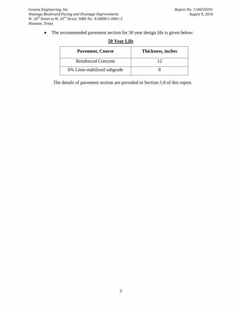
The recommended pavement section for 50 year design life is given below:
50 Year Life
Pavement, Course Thickness, inches
Reinforced Concrete 12
6% Lime-stabilized subgrade 8
The details of pavement section are provided in Section 5.8 of this report.

Geotest Engineering, Inc. Report No. 1140210101
Watonga Boulevard Paving and Drainage Improvements August 9, 2016
W. 34th
Street to W. 43rd
Street; WBS No. N-000811-0001-3
Houston, Texas
4
1.0 INTRODUCTION
1.1 General
The City of Houston selected IDC, Inc. (Engineer) to perform engineering services for the
design of reconstruction of Watonga Boulevard between W. 34th
Street and 43rd
Street in Houston,
Texas. IDC, Inc. retained Geotest Engineering, Inc. (GEI) as part of the design team to perform
geotechnical investigation for the above project.
1.2 Authorization
This study was authorized by Subcontract Services Agreement on April 28, 2015 by
accepting our proposal No. 1140338199 dated February 18, 2015 and e-mail Notice to Proceed on
October 23, 2015 for additional scope of 16-inch water line aerial crossing bridge at Brickhouse
Gully by accepting our Proposal No. 1140371499, dated October 6, 2015.
1.3 Location and Description of Project
The project is located along Watonga Boulevard between W. 34th to 43
rd Street in Houston,
Texas. The project alignment is bounded by Mangum Road to the west, White Oak Bayou to the east,
W. 34th Street to the south and W. 43
rd Street to the north, within the Key Map Page and Grid 451R, M,
& H.
The project calls for replacing 5,400 LF of the existing 4-lane boulevard section of Watonga
Boulevard from W. 34th Street to W. 43
rd Street with same four lane configuration along with storm
sewer and water line replacement. The proposed storm sewer is 24, 30 and 36 inches in size and will
be approximately 4.5 to 16.0 feet deep below existing grade. The proposed water line is 16 inches in
size and approximately 5.0 to 16.0 feet deep. The project also involves the design of an aerial crossing
bridge for the 16-inch water line at the crossing of the Brickhouse Gully. The project does not,
however, include vehicular bridge widening or bridge replacement at the crossing of Brickhouse Gully.
The proposed storm sewer discharges into the Brickhouse Gully. The project includes replacement of
Geotest Engineering, Inc. Report No. 1140210101
Watonga Boulevard Paving and Drainage Improvements August 9, 2016
W. 34th
Street to W. 43rd
Street; WBS No. N-000811-0001-3
Houston, Texas
5
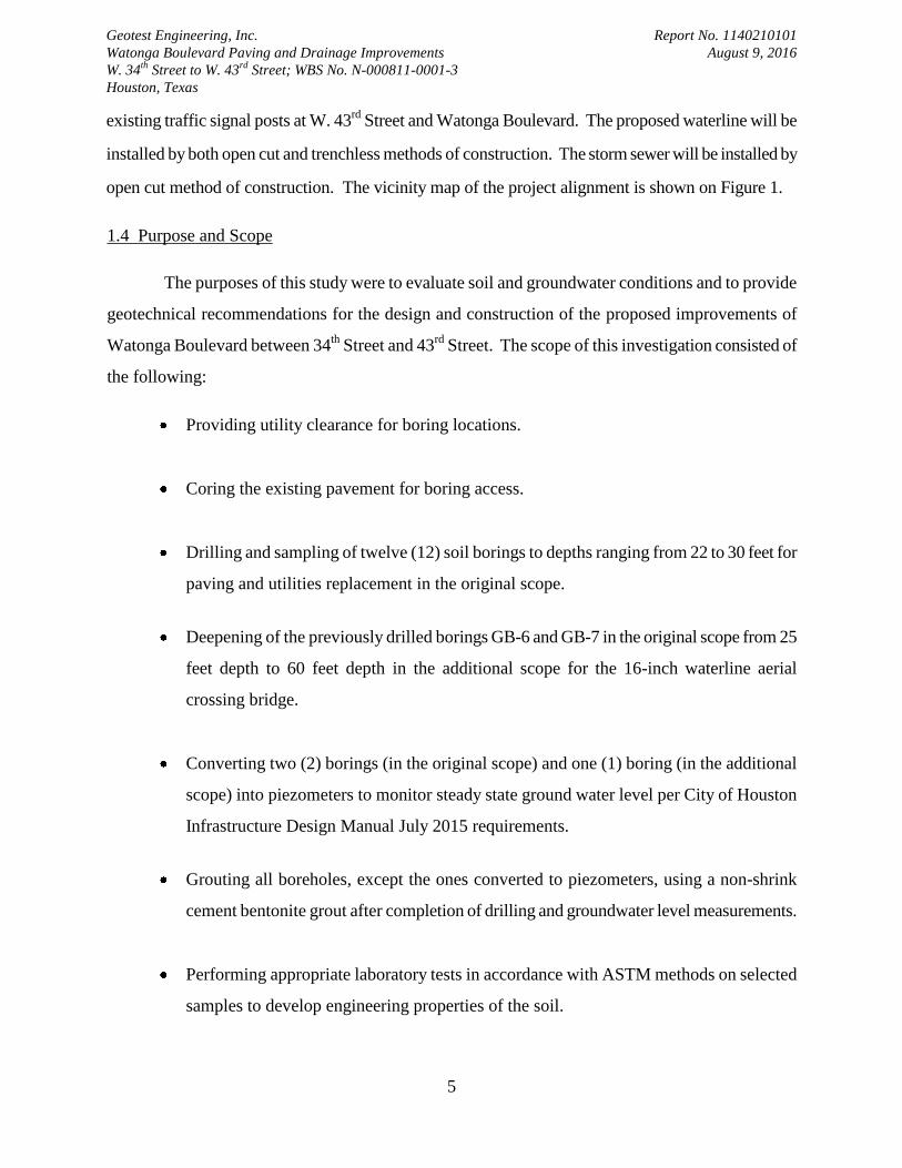
existing traffic signal posts at W. 43rd
Street and Watonga Boulevard. The proposed waterline will be
installed by both open cut and trenchless methods of construction. The storm sewer will be installed by
open cut method of construction. The vicinity map of the project alignment is shown on Figure 1.
1.4 Purpose and Scope
The purposes of this study were to evaluate soil and groundwater conditions and to provide
geotechnical recommendations for the design and construction of the proposed improvements of
Watonga Boulevard between 34th
Street and 43rd
Street. The scope of this investigation consisted of
the following:
Providing utility clearance for boring locations.
Coring the existing pavement for boring access.
Drilling and sampling of twelve (12) soil borings to depths ranging from 22 to 30 feet for
paving and utilities replacement in the original scope.
Deepening of the previously drilled borings GB-6 and GB-7 in the original scope from 25
feet depth to 60 feet depth in the additional scope for the 16-inch waterline aerial
crossing bridge.
Converting two (2) borings (in the original scope) and one (1) boring (in the additional
scope) into piezometers to monitor steady state ground water level per City of Houston
Infrastructure Design Manual July 2015 requirements.
Grouting all boreholes, except the ones converted to piezometers, using a non-shrink
cement bentonite grout after completion of drilling and groundwater level measurements.
Performing appropriate laboratory tests in accordance with ASTM methods on selected
samples to develop engineering properties of the soil.

Geotest Engineering, Inc. Report No. 1140210101
Watonga Boulevard Paving and Drainage Improvements August 9, 2016
W. 34th
Street to W. 43rd
Street; WBS No. N-000811-0001-3
Houston, Texas
6
Reviewing available fault information to evaluate the potential for known active faults
that may impact the project.
Performing engineering analyses in accordance with the City of Houston Infrastructure
Design Manual (July 2015) to develop geotechnical recommendations for the design of
pavement reconstruction including subgrade stabilization, bedding and backfill for
utilities, groundwater control for open cut constructions and trenchless installation, 16-
inch waterline aerial crossing bridge, and traffic signal post foundation.
Preparing a geotechnical report that includes all field data, laboratory test data and
geotechnical recommendations.
Preparing a separate soil type report for trench (open cut) excavation.

Geotest Engineering, Inc. Report No. 1140210101
Watonga Boulevard Paving and Drainage Improvements August 9, 2016
W. 34th
Street to W. 43rd
Street; WBS No. N-000811-0001-3
Houston, Texas
7
2.0 FIELD INVESTIGATION
2.1 General
After obtaining the utilities clearance of the marked twelve (12) borings in the field, the
borings were drilled to the explored depths utilizing a truck mounted drilling rig. Traffic control
devices and personnel were utilized during coring and drilling to maintain safety of drill crew and
people driving in the streets. All the drilling and sampling were performed in accordance with
appropriate ASTM procedures.
2.2 Geotechnical Borings
Subsurface conditions for the project alignment were explored by drilling and sampling twelve
(12) soil borings (designated as GB-1 through GB-12) to depths ranging from 22 to 30 feet in the
original scope and deepening of borings GB-6 and GB-7 (designated as GB-6A and GB-7A) to 60 feet
in the additional scope. During the field investigation, obstruction was encountered at the location of
boring GB-1 at a depth of 6 feet. Offset boring GB-1A was drilled to the proposed explored depth of
27 feet. Borings GB-6 and GB-7 were deepened to 60 feet depth from the original depth of 25 feet for
the proposed 16-inch waterline aerial crossing bridge. The approximate boring locations are shown on
Figures 2.1 through 2.3, Plan of Borings. Survey information (Northing and Easting coordinates and
ground surface elevation) of completed borings was provided to us by IDC, Inc. The survey
information of completed borings is summarized in Table 1.
In general, samples were obtained continuously to a depth of 20 feet and intermittently at 5
feet intervals afterwards to the termination depths of 30 and 60 feet for all borings, except borings
GB-2 and GB-3 where continuous sampling was done to a depth of 22 feet. Cohesive soils were
obtained with a 3-inch thin-walled tube sampler in general accordance with ASTM Method D1587
and samples of granular soils were obtained with a 2-inch diameter split-barrel sampler in general
accordance with ASTM Method D1586. Each sample was removed from the sampler in the field,
carefully examined and then logged by an experienced soils technician. Suitable portions of each
sample were sealed and packaged for transportation to Geotest’s Laboratory. The shear strength of

Geotest Engineering, Inc. Report No. 1140210101
Watonga Boulevard Paving and Drainage Improvements August 9, 2016
W. 34th
Street to W. 43rd
Street; WBS No. N-000811-0001-3
Houston, Texas
8
cohesive soil samples was estimated using a pocket penetrometer in the field. Driving resistances for
the split-barrel sampler were recorded as "Blows per Foot" on the boring logs. All the borings,
except the ones converted to piezometers, were grouted with cement-bentonite grout after
completion of drilling and obtaining water level measurements (if any).
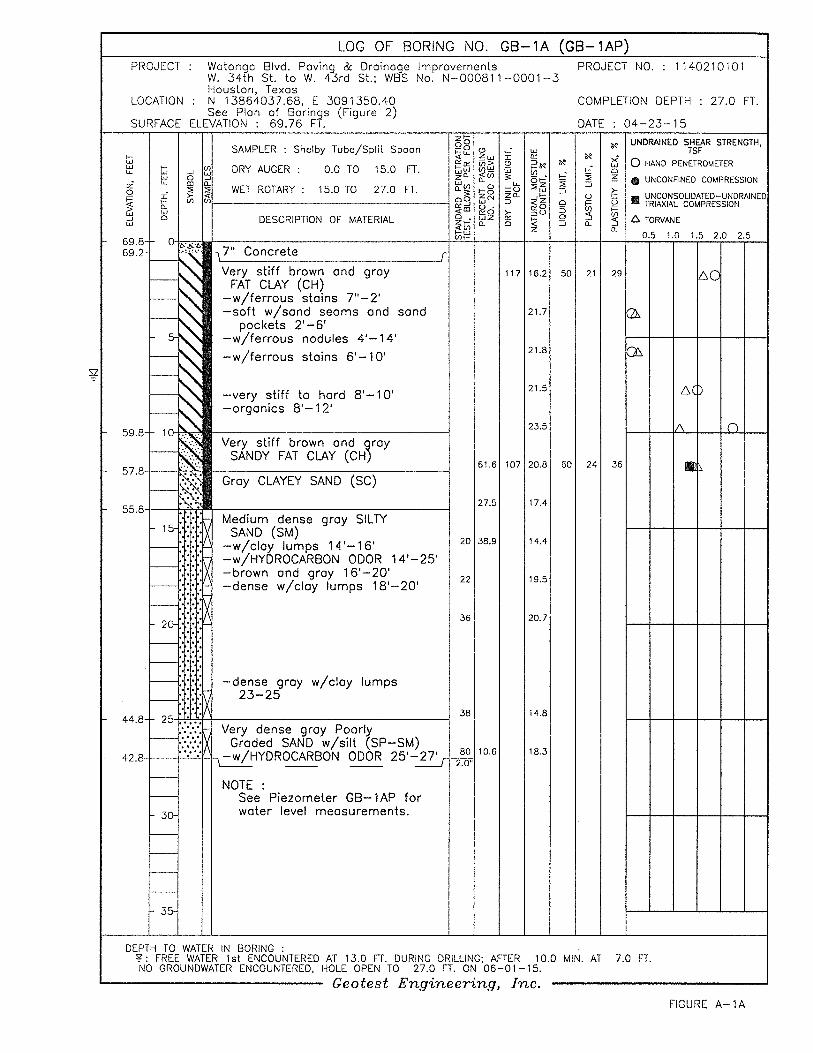
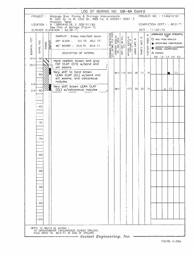
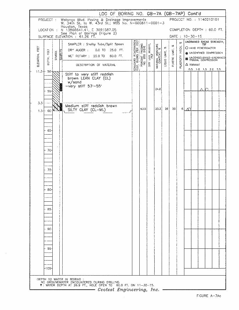
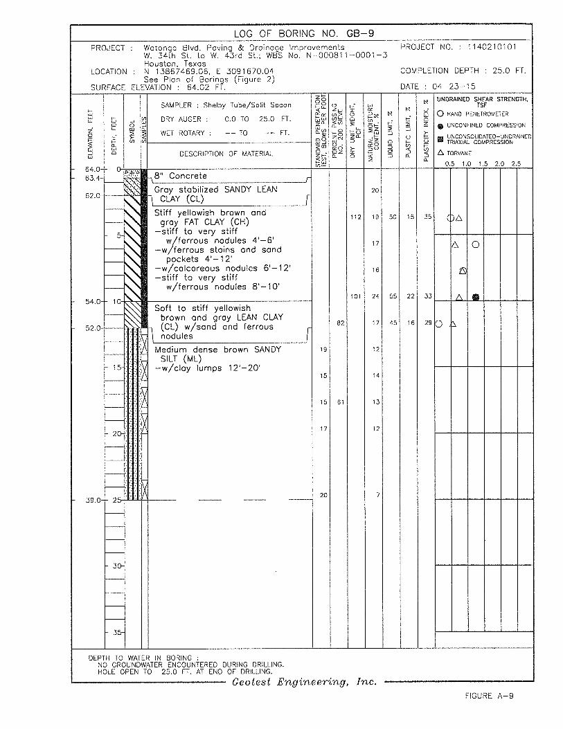
Detailed descriptions of the soils encountered in the borings are given on the boring logs
presented on Figures A-1 through A-12 and A-6A and A-7A in Appendix A. A key to symbols and
terms used on boring logs is given on Figure A-13 in Appendix A.
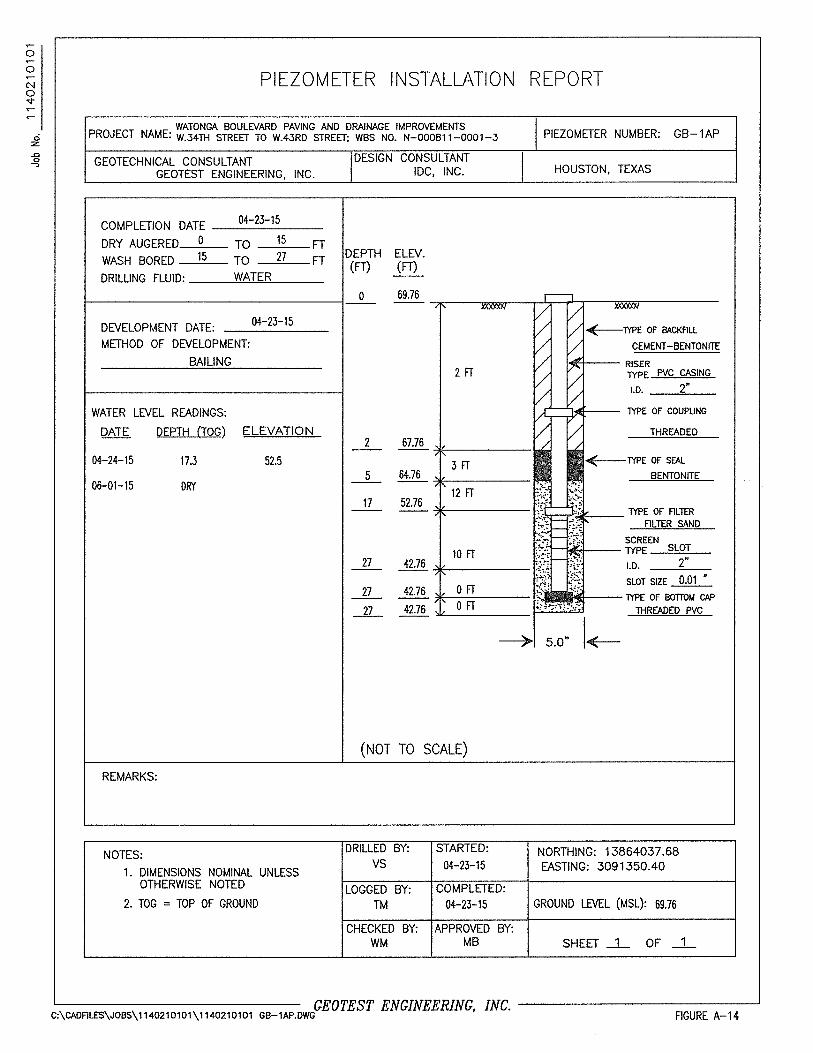
2.3 Piezometer Installation
During the field investigation, a total of three (3) piezometers were installed (two (2) in the
original scope and one (1) in the additional scope) in the open boreholes of borings GB-1A, GB-7A
and GB-12. The location of the piezometers, designated as GB-1AP, GB-7AP and GB-12P, is
shown on Figure 2.1 through 2.3 (Plan of Borings). The piezometer installation report showing the
details of the construction of the piezometers are provided on Figures A-14, A-15 and A-16 in
Appendix A. After taking the final water level measurements, the piezometers were abandoned in
place. The piezometer abandonment reports are presented in Appendix C.

Geotest Engineering, Inc. Report No. 1140210101
Watonga Boulevard Paving and Drainage Improvements August 9, 2016
W. 34th
Street to W. 43rd
Street; WBS No. N-000811-0001-3
Houston, Texas
9
3.0 LABORATORY TESTING
The laboratory testing program was designed to evaluate the pertinent physical properties and
shear strength characteristics of the subsurface soils. Classification tests were performed on selected
samples to aid in soil classification. All the tests were performed in accordance with ASTM Standards.
Undrained shear strengths of selected cohesive samples were measured by unconsolidated
undrained (UU) triaxial compression tests (ASTM D2850). The results of the UU triaxial compression
tests are plotted on the boring logs as solid squares. The shear strength of cohesive samples was
measured in the field with a calibrated hand pocket penetrometer and also in the laboratory with a
Torvane. The shear strength values obtained from the penetrometer and Torvane are plotted on the
boring logs as open circles and triangles, respectively.
Measurements of moisture content and dry unit weight were taken for each UU triaxial
compression test sample. Moisture content (ASTM D2216) measurements were also made on other
samples to define the moisture profile at each boring location. The liquid and plastic limit tests
(ASTM D4318) and percent passing No. 200 sieves (ASTM D1140) were performed on appropriate
samples. Sieve analysis (ASTM D422) was also performed on selected cohesionless soil samples.
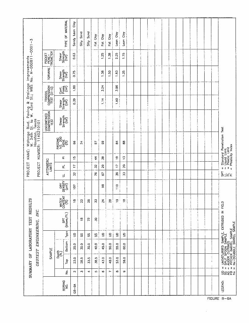
The result of all tests are tabulated or summarized on the boring logs presented on Figures
A-1 through A-12 in Appendix A. The summary of laboratory tests is also presented in a tabular
form on Figures B-1 through B-12 in Appendix B. The grain size distribution curves are presented
on Figures B-13 through B-18 in Appendix B.
Geotest Engineering, Inc. Report No. 1140210101
Watonga Boulevard Paving and Drainage Improvements August 9, 2016
W. 34th
Street to W. 43rd
Street; WBS No. N-000811-0001-3
Houston, Texas
10
4.0 SUBSURFACE CONDITIONS
4.1 Geology
The project area lies in the boundary of the Beaumont Formation and the Lissie Formation.
Both the Beaumont and Lissie formations are part of the fluvial and marine coastal complex resulting
from the glacial cycles within the Pleistocene (10,000 years to 2 million years ago)/Holocene (2,500
years to 10,000 years ago) epoch. Seaward the lithologies are primarily dominated by clays, often
interspersed with coarser sediments, primarily silts and sands. The clays of the Beaumont formation
are overconsolidated and slickensided as a result of exposure to weathering during glacial
retrenchment and cyclic wetting and drying. Northern portions of Harris County are under the
influence of the drainage systems established by rivers such as the Brazos and the San Jacinto. The
lithologic pattern generally includes silt, sand and clay with minor amounts of calcareous nodules
and iron oxide. Various mineral impregnations are associated with the lithologies. Primary among
these are the ferruginous-iron-based and calcareous minerals, which include calcium carbonate.
These minerals impart an acidic or alkaline characteristic to soils.
Based on the Houston Sheet of Geologic Atlas of Texas (Bureau of Economic Geology,
University of Texas, 1982), the section of Watonga Boulevard proposed reconstruction lies within
the boundaries of the Lissie Formation’s surface exposure. The upper zones of the Lissie Formation
consist of clay, silt, sand and minor amounts of siliceous gravel in areas to the northwest. The Lissie
Formation is characterized by a featureless flat to gently rolling surface and fluviatile deposition.
The calcareous deposits and concentrations of calcium carbonate, iron oxide and iron-manganese
oxides are common in the zone of weathering.
4.2 General Fault Information
A review of information in the Geotest library, relating to known surface and subsurface
geologic faults in the general area of the project alignment, was undertaken. The available
information consisted of U.S. Geological and NASA maps, open file reports and information
contained in our files relating to geologic faults for the project alignment.

Geotest Engineering, Inc. Report No. 1140210101
Watonga Boulevard Paving and Drainage Improvements August 9, 2016
W. 34th
Street to W. 43rd
Street; WBS No. N-000811-0001-3
Houston, Texas
11
Based on the available information from U.S. Geological Survey (USGS) Maps and
information contained in Geotest Library relating to geologic faults for the project alignment, the
nearest known fault is Long Point Fault which is approximately 1 mile southwest from the middle of
the project alignment. The expected projection of the fault trace may not cross the project alignment.
Hence, a Phase I Geological Fault Study may not be needed for the project.
4.3 Existing Paving
The existing paving as obtained in the soil borings GB-1A through GB-12, GB-6A and GB-
7A consists of 6.5 to 9.0 inches of concrete, except in boring GB-11 where 4.5 inch of concrete was
overlaid by a 3.0 inch of asphalt.
The details of the existing pavement thickness at each of the boring locations are summarized
below:
Boring Nos.
Asphalt
Thickness
(in)
Concrete
Thickness
(in)
Total (in.)
GB-1A (GB-
1AP)
-- 7.0 7.0
GB-2 -- 7.5 7.5
GB-3 -- 6.5 6.5
GB-4 -- 7.0 7.0
GB-5 -- 7.0 7.0
GB-6 -- 8.0 8.0
GB-6A -- 8.0 8.0
GB-7 -- 8.5 8.5
GB-7A -- 8.0 8.0
GB-8 -- 8.0 8.0
GB-9 -- 8.0 8.0
GB-10 -- 8.0 8.0
GB-11 3.0 4.5 7.5
GB-12 -- 9.0 9.0
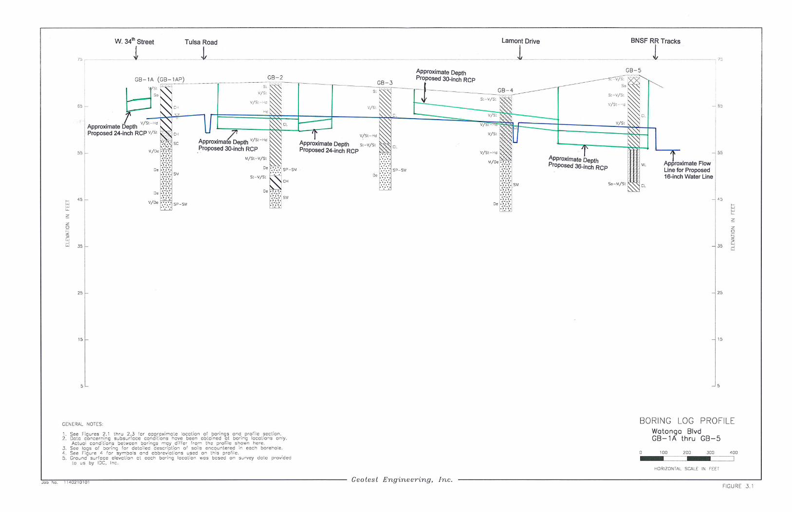
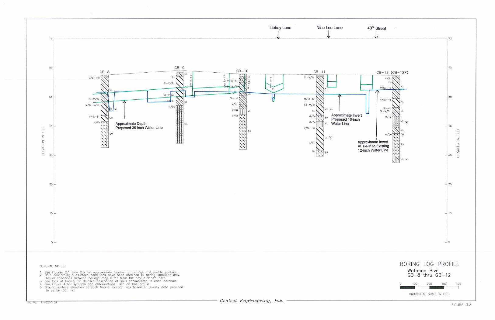
4.4 Soils Stratigraphy
Based on the subsurface soils encountered in the boreholes, three (3) boring log profiles were
developed and are presented on Figures 3.1 through 3.3. To the left of each boring shown on the

Geotest Engineering, Inc. Report No. 1140210101
Watonga Boulevard Paving and Drainage Improvements August 9, 2016
W. 34th
Street to W. 43rd
Street; WBS No. N-000811-0001-3
Houston, Texas
12
profile is an indication of the consistency or density of each stratum. More than one consistency for
an individual stratum indicates that the consistency is different at different depths within the stratum.
For cohesive soils, consistency is related to the undrained shear strength of the soil. For
cohesionless soils, the density of soil is measured by standard penetration test blows of the soil. To
the right of each boring shown on the profile is the overall classification of the soil contained within
each stratum. The symbols and abbreviations used on the boring log profile are given on Figure 4.
The soil classification is based on ASTM Standards.
The subsurface soil beneath pavement as encountered in borings GB-1A through GB-12 and as
shown in the boring log profiles presented on Figures 3.1 through 3.3 along Watonga Boulevard
between W. 34th and W. 43
rd Street generally consists of cohesive soils intermittent with and/or
underlain by cohesionless soils to the explored depths of 22 to 60 feet. The cohesive soils consist of
soft to hard gray, brown, yellowish brown and reddish brown sandy silty clay, silty clay, sandy lean
clay, lean clay with sand, lean clay, sandy fat clay, fat clay w/sand and fat clay. The cohesionless soils
consist of medium dense to very dense gray, brown and reddish brown poorly graded sand w/silt, silty
sand, clayey sand, sandy silt, silt w/sand and clayey silt. Fill materials consisting of stiff to very stiff
brown and gray lean clay w/sand, calcareous and ferrous nodules and shell fragments were encountered
beneath the pavement to a depth of 2 to 6 feet in borings GB-5 and GB-6.
The Sandy Fat Clay, Fat Clay w/sand and Fat Clay are of high to very high plasticity with
liquid limits ranging from 50 to 76 and plasticity indices ranging from 26 to 44. The Lean Clay, Lean
Clay w/sand and Sandy Lean Clay are of medium plasticity with liquid limits ranging from 26 to 46 and
plasticity indices ranging from 9 to 31. The percent fines (percent passing No. 200 sieve) of Poorly
Graded Sand with silt range from 9 to 11 percent. The percent fines of Silty Sand and Clayey Sand
range from 14 to 43 percent. The percent fines of Sandy Silt ranges between 58 to 68 percent. The
percent fines of the Sandy Silty Clay range between 52 to 69 percent. The percent fines of Sandy Lean
Clay range from 54 to 69 percent. The percent fines of Sandy Fat Clay is about 62 percent. The
percent fines of Silt w/sand is about 81 percent and the percent fines of clayey silt is about 100 percent.
The percent fines of Lean Clay with sand and Fat Clay with sand range from 72 to 85 percent. The
percent fines of Lean Clay and Fat Clay ranges from 88 to 100 percent.

Geotest Engineering, Inc. Report No. 1140210101
Watonga Boulevard Paving and Drainage Improvements August 9, 2016
W. 34th
Street to W. 43rd
Street; WBS No. N-000811-0001-3
Houston, Texas
13
4.5 Water Levels
Groundwater was first encountered at depths ranging from 13 to 23 feet during drilling in
borings GB-1A, GB-7, GB-11 and GB-12. The groundwater level, measured 15 minutes after water
was first encountered, ranged from 7.0 to 21.8 feet in these borings. In piezometer borings GB-1AP,
GB-7AP and GB-12P, the water level measured on June 1, 2015 and November 30, 2015 was at 26.9
feet and 16.5 feet in Piezometers GB-7AP and GB-12P, respectively and no water was noted in
Piezometer GB-1AP. The detailed water level information as encountered in borings and
piezometers is presented in the table below.
Boring No.
Groundwater
Depth During
Drilling (ft)
(After 15 min)
Groundwater
Depth 30 Days
After Drilling
(ft)
GB-1A (GB-1AP) 7.0 None (6-1-15)
GB-6 -- --
GB-6A -- --
GB-7 21.0 N/A
GB-7A (GB-7AP) -- 26.9 (11-30-15)
GB-11 21.8 N/A
GB-12 (GB-12P) 20.6 16.5 (6-1-15)
Note: In all other borings, GB-2 through GB-6 and GB-8 through GB-10, no groundwater was encountered
during drilling.
However, it should be noted that various environmental and man-made factors such as
amount of precipitation, nearby subsurface construction activities, and change in area drainage can
substantially influence the groundwater level.
4.6 Environmental Concerns
Hydrocarbon odor was encountered during drilling in boring GB-1A between the depths of
14 to 27 feet. Geotest Engineering, Inc. has performed a Phase I and Phase II Environmental
Geotest Engineering, Inc. Report No. 1140210101
Watonga Boulevard Paving and Drainage Improvements August 9, 2016
W. 34th
Street to W. 43rd
Street; WBS No. N-000811-0001-3
Houston, Texas
14
Assessment for the project areas and the findings of the studies are included in reports 1130019301
and 1130021801. It should be noted that the recommended potentially petroleum contaminated area
(PPCA) given in Phase II ESA report (Report No. 1130021801) ends about 30 feet before the
location of boring GB-1A. To address the issue, the following alternatives were proposed by GEI:
Perform an additional environmental boring and testing to confirm the limits of the
PPCA.
Alternatively, issue an addendum report to extend the limits of PPCA to station
number 104+20 to 107+50 (to the next environmental boring).

Geotest Engineering, Inc. Report No. 1140210101
Watonga Boulevard Paving and Drainage Improvements August 9, 2016
W. 34th
Street to W. 43rd
Street; WBS No. N-000811-0001-3
Houston, Texas
15
5.0 ENGINEERING ANALYSES AND RECOMMENDATIONS
5.1 General
The project calls for replacing the existing 5,400 LF of 4-lane boulevard section of Watonga
Boulevard from W. 34th Street to W. 43
rd Street with same four lane configuration, storm sewer and
water line replacement. The proposed storm sewer is 24, 30, 36 inches in size and will be
approximately 4.5 to 16.0 feet deep below existing grade. The proposed water line is 16-inches in size
and approximately 5.0 to 16.0 feet deep. The project also involves the design of an aerial crossing
bridge at the crossing of the Brickhouse Gully for the 16-inch waterline. The project does not,
however, include vehicular bridge widening or bridge replacement at the crossing of Brickhouse Gully.
The proposed storm sewer discharges into the Brickhouse Gully. The project includes replacement of
existing traffic signal posts at W. 43rd
Street and Watonga Boulevard. The proposed waterline will be
installed by both open cut and trenchless methods of construction. The storm sewer will be installed by
open cut method of construction.
5.2 Trench Excavation
Based on the information provided to us by IDC, Inc., it is understood that the storm sewer
will be installed by open cut method of construction and waterline will be installed by open cut and
augering/trenchless methods. The following subsections provide information for the design and
construction of open cut method of installation and open excavation for auger pits for trenchless
installation.
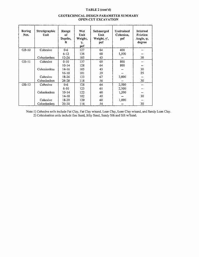
5.2.1 Geotechnical Parameters. Based on the soil conditions revealed by the borings GB-1A
through GB-12, geotechnical parameters were developed for the design of open cut installation for
the proposed storm sewer and water line and open excavation for auger pits for the waterline
installation. The design parameters are provided in Table 2. For design, the groundwater level
should be assumed to exist at the ground surface.

Geotest Engineering, Inc. Report No. 1140210101
Watonga Boulevard Paving and Drainage Improvements August 9, 2016
W. 34th
Street to W. 43rd
Street; WBS No. N-000811-0001-3
Houston, Texas
16
5.2.2 Excavation Stability. The open excavation may be shored or laid back to a stable slope
or supported by some other equivalent means used to provide safety for workers and adjacent
structures, if any. The excavating operations should be in accordance with OSHA Standards, OSHA
2207, Subpart P, latest revision and the City of Houston Standard Specification.
Excavation Shallower Than 5 Feet - Excavations that are less than 5 feet deep (critical
height) should be effectively protected when an indication of dangerous ground movement is
anticipated.
Excavations Deeper Than 5 Feet - Excavations that are deeper than 5 feet should be sloped,
shored, sheeted, braced or laid back to a stable slope or supported by some other equivalent
means or protection such that workers are not exposed to moving ground or cave-ins. The
slopes and shoring should be in accordance with the trench safety requirements as per OSHA
Standards. The following items provide design criteria for excavation stability.
(i) OSHA Soil Type. Based on the soil conditions revealed by borings drilled for this
study and assumed groundwater level at surface, OSHA soil type “C” should be used
for determination of allowable maximum slope and/or the design of shoring along the
alignment for full proposed depth of open excavation. For shoring deeper than 20
feet, an engineering evaluation is required.
(ii) Excavation Support Earth Pressure. Based on the subsurface conditions indicated by
our field investigation and laboratory testing results, excavation support earth
pressure diagrams are developed and are presented on Figures 5.1 through 5.3. These
pressure diagrams can be used for the design of temporary trench bracing. For a
trench box, a lateral earth pressure resulting from an equivalent fluid with a unit
weight of 92 pcf can be used. The effects of any surcharge loads at the ground
surface should be added to the computed lateral earth pressures. A surcharge load, q,
will typically result in a lateral load equal to 0.5q. The above value of equivalent
fluid pressure is based on assumption that the groundwater level is near the ground
surface, since these conditions may exist after a heavy rain or flooding.

Geotest Engineering, Inc. Report No. 1140210101
Watonga Boulevard Paving and Drainage Improvements August 9, 2016
W. 34th
Street to W. 43rd
Street; WBS No. N-000811-0001-3
Houston, Texas
17
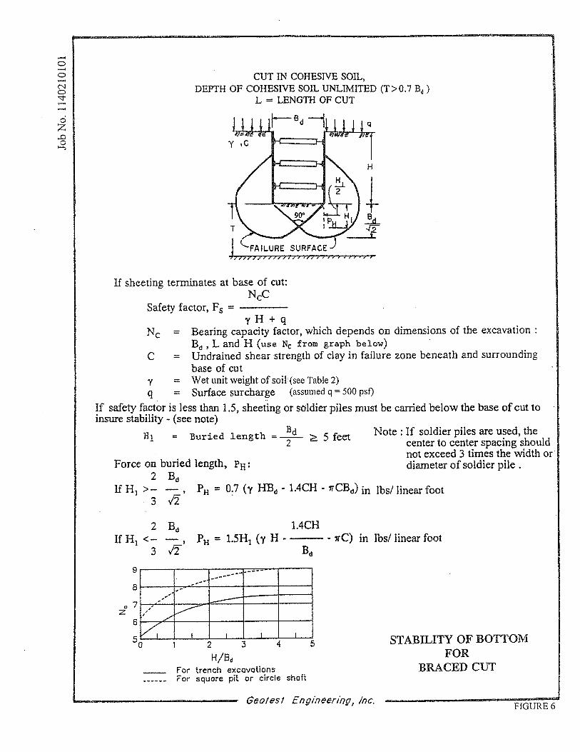
(iii) Bottom Stability. In braced cuts, if tight sheeting is terminated at the base of the cut,
the bottom of the excavation can become unstable. The parameters that govern the
stability of the excavation base are the soil shear strength and the differential
hydrostatic head between the groundwater level within the retained soils and the
groundwater level at the interior of the trench excavation. For cuts in cohesive soils
as predominantly encountered for excavation depths shallower than 7 feet, the bottom
stability can be evaluated as outlined on Figure 6. However, at locations near borings
GB-1, GB-5, GB-7, GB-8, GB-9 and GB-11 where cohesionless soils were
encountered at invert or within 3 feet to 5 feet of invert depth, dewatering will be
necessary to avoid bottom stability problems.
5.2.3 Groundwater Control. Excavations for waterline and storm sewer lines may encounter
groundwater seepage to varying degrees depending upon groundwater conditions at the time of
construction and the location and depth of excavation. Based on the soil conditions identified in the
borings, all excavations (for excavation depths shallower than 7 feet) will be in cohesive soils. In
general for cohesive soils as encountered in all the borings for excavation depths shallower than 7
feet, groundwater (if encountered) may be managed by collection in excavation bottom sumps for
pumped disposal. However, for deeper excavations due to the presence of water bearing
cohesionless soils at invert or within 3 to 5 feet of invert depth at locations near borings GB-1, GB-5,
GB-7, GB-8, GB-9 and GB-11, dewatering will be required. Dewatering such as vacuum well points
up to 15 feet may be required to lower the ground water level to at least 5 feet below the bottom of
excavation. The dewatering system should be pumping well ahead of time before excavation starts
so that a steady state condition (groundwater elevation at least 5 feet below the proposed excavation
bottom) is achieved. It is recommended that the actual groundwater conditions should be verified by
the contractor at the time of construction and that groundwater control should be performed in
general accordance with the City of Houston Standard Specifications, Section 01578.
5.2.4 Bedding and Backfill for Water Line and Storm Sewer. In general, excavation and
backfill for utilities should be designed and constructed in accordance with the City of Houston
Standard Specification No. 02317, Subsection 3.09 and 3.10 “Excavation and Backfill for Utilities.”

Geotest Engineering, Inc. Report No. 1140210101
Watonga Boulevard Paving and Drainage Improvements August 9, 2016
W. 34th
Street to W. 43rd
Street; WBS No. N-000811-0001-3
Houston, Texas
18
Bedding and backfill for storm sewer should be in accordance with City of Houston Standard
Specification Section 02317 and Drawing No. 02317-03. Bedding and backfill for water line should
be in accordance with City of Houston Standard Specification Section 02317 and Drawing No.
02317-04.
5.2.5 Influence of Open Cut Excavations on Adjacent Structures. Based on the information
provided to us, open cut excavations for the proposed waterline are generally along the streets and
there are no immediate building structures along the proposed excavations except at the bridge at the
Brickhouse Gully, where open excavations for storm sewer may be close to the bridge structure.
Underground utilities and adjacent structures to the excavations should be properly protected during
excavations and monitored during and after the excavations and during dewatering.
5.3 Trenchless Installation
It is understood that the proposed 16-inch waterline along Watonga Boulevard will be
installed by trenchless method of construction at the railroad and street crossings.
5.3.1 Geotechnical Parameters for Trenchless Installation. Based on the soil conditions
revealed by borings GB-1A through GB-12 and laboratory test data, geotechnical design parameters
were developed for cohesive soils and cohesionless soils and are provided in Table 3. The cohesive
soils include fat clays, fat clays with sand, lean clays, lean clays with sand, sandy silty clay and sandy
lean clays. The cohesionless soils include poorly graded sand w/silt, silty sand, sandy silt, and silt
with sand. For design conditions, the groundwater levels should be assumed to exist at the ground
surface.
5.3.2 Earth Pressure on Pipe and Casing. The earth pressures on the pipe and casing should
be determined from Figure 7. Equations to calculate the tunnel liner loads are also shown in Figure
7. For pipe crossing under major roads, the stress due to traffic loads should be considered.
Geotest Engineering, Inc. Report No. 1140210101
Watonga Boulevard Paving and Drainage Improvements August 9, 2016
W. 34th
Street to W. 43rd
Street; WBS No. N-000811-0001-3
Houston, Texas
19
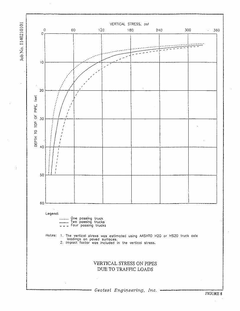
5.3.3 Live Loads on Pipeline Due to Vehicular Traffic and Rail Traffic. Loads on pipe due
to traffic should be considered. A graph providing calculated vertical stress on pipe due to vehicular
and rail traffic loads are given on Figures 8 and 9, respectively.
5.3.4 Insertion/Reception Pits. The insertion/reception pits for trenchless installation may be
constructed by retained excavation. Retained excavations generally require less ground surface area
than open cut excavation with laid back slopes. The retention system can consist of driven sheetpile,
liner plates, solider pile/lagging, driven planking, or ring beams and timber lagging. The items
pertaining to the design criteria for retained excavation stability should be in accordance with
guidelines as outlined in Section 5.2.2 of this report.
5.3.5 Insertion/Reception Pit Backfill. The excavated insertion/reception pits should be
backfilled per the City of Houston Standard Specification Section No. 02317 "Excavation and
Backfill for Utilities" and Section No. 02447 "Auguring Pipe and Conduit" and Drawing No. 02447-
01.
5.3.6 Carrier Pipe Design Parameters. Carrier pipe must be sufficiently strong to withstand
anticipated long-term ground loads and must not be subject to deterioration by substance either in the
ground or in the tunnel. The carrier pipe design should include consideration of not only the loads
applied to the pipe but also factors other than soil loading. These factors could include minimum
structural code requirements, loading from pipe jacking operations and other construction loads. The
drained geotechnical design parameters given in Table 3 should be used in analyzing the soil
structure intersection of the carrier pipe.
5.3.7 Influence of Trenchless Operation on Adjacent Structures. Surface and near-surface
structures near the pipe and casing augering primarily consist of railroad tracks, city streets and
public utilities.
Ground movement, in terms of loss of ground or ground lost, is commonly associated with soft
ground augering. If such ground movement is excessive, it may cause damage to the structures, roads

Geotest Engineering, Inc. Report No. 1140210101
Watonga Boulevard Paving and Drainage Improvements August 9, 2016
W. 34th
Street to W. 43rd
Street; WBS No. N-000811-0001-3
Houston, Texas
20
and services located above the auger casing. While ground movement cannot be eliminated, it can be
controlled within certain limits by the use of proper construction techniques and good quality
workmanship. These include, but are not limited to, prevention of excessive ground loss during
trenchless operation with the use of grouting and filling the annular space between the pipe or casing
and the surrounding soil and prevention of undue loss of fines through dewatering.
The selection and execution of trenchless methods that are best suited to anticipated ground
conditions along the proposed auger casing are, in fact, the contractor’s primary contribution to
successful completion of the proposed auger casing. Review of the boring logs revealed that the
ground conditions for augering (excavation face) will be primarily through medium stiff to hard Fat
Clays, Lean Clays, Sandy-Silty Clay and medium dense Sandy Silt and Silty Sand and the ground in
this area may be expected to behave as firm to raveling ground and some squeezing ground, where
cohesive soils are encountered. However, due to spacing of borings, soil conditions other than those
encountered in the borings could exist. In view of the sandy silt and silty sand encountered within one
bore diameter or at invert near borings GB-1, GB-4, GB-5, GB-8, GB-9, GB-11 and GB-12, dewatering
may be required.
The proposed auger casing is parallel with or crosses beneath a number of water, telephone and
storm and sanitary sewer lines. The largest potential problems from utilities may result from:
Leaking water pipes
Gas pipe breakage leading to a potential explosion
Breakage of storm or sanitary sewers
In general, it is the contractor’s responsibility to investigate these and other possible third party
interactions along the proposed water line alignment and to accommodate all of these interactions with
the use of good construction methods.

Geotest Engineering, Inc. Report No. 1140210101
Watonga Boulevard Paving and Drainage Improvements August 9, 2016
W. 34th
Street to W. 43rd
Street; WBS No. N-000811-0001-3
Houston, Texas
21
5.4 Piping System Thrust Restraint
Unbalanced thrust forces will occur at any point in the pipe where the direction or cross
sectional area of the flow changes. The force diagram shown in Figure 10 illustrates the thrust force
generated by flow at a bend in the pipe. The equations for computing this thrust force are also given
in this figure. The thrust force will often require more resistance or support than is available just
from the pipe bearing against the backfill. In order to prevent intolerable movement and
overstressing of the pipe, suitable buttressing should be provided.
Based on the drawings provided to us, it was noted that several horizontal bends are proposed
which may require restraint in addition to that supplied by the pipe bearing backfill. In general,
thrust blocks, both horizontal and vertical and restrained joints are common methods of supplying
additional reaction. However, it is noted that restrained joints are considered for supplying
additional reaction for the project and is discussed below.
5.4.1 Restrained Joints. Where thrust blocks are not practical, restrained joints, allowing
thrust and shear forces to be transmitted across the pipe joints, are employed to allow a number of
pipe sections to act integrally in bearing. The equations necessary to determine the restrained pipe
length on each side of the bend are given below:
)(
)1(
wpe WWW
CosPAL
where, L = restrained pipe length on each side of the bend, in feet
P = internal pressure, in pounds per square inch
A = cross sectional area of first unrestrained pipe joint, in square inches
= deflection angle of bend, in degrees
= co-efficient of friction between pipe and soil (recommended 0.3)
eW = overburden load, in pounds per liner foot = b BcH
pW = weight of pipe, in pounds per linear foot

Geotest Engineering, Inc. Report No. 1140210101
Watonga Boulevard Paving and Drainage Improvements August 9, 2016
W. 34th
Street to W. 43rd
Street; WBS No. N-000811-0001-3
Houston, Texas
22
wW = weight of water in pipe, in pounds per linear foot
b = wet unit weight of backfill material, in pounds per cubic foot
(recommended 120 pcf)
Bc = pipe outer diameter, in feet
H = earth cover, in feet
Reinforced concrete encasement may be used in lieu of the manufactured joint restrained
system. The equations and soil parameters given above can be used for the design of reinforced
concrete encasement.
5.5 Structures
5.5.1 Description. The structure associated with this project will be new manholes. The new
manholes for storm sewer will be placed at depths ranging from 4.5 to 16.0 feet.
5.5.2 Foundation Conditions. Based on the soil conditions revealed by the borings GB-1
through GB-12, the manholes bottom will be in soft to hard fat clay, lean cay, lean clay with sand,
sandy silty clay, clayey sand, medium dense sandy silt and silty sand.
5.5.3 Foundation Design Recommendations. The following items provide recommendations
and design criteria for construction of the new manholes.
Allowable Bearing Pressures. The mat foundation for supporting the new manholes
placed at depths ranging from 4.5 to 16.0 feet [into soft to hard fat clay, lean cay, lean
clay with sand, sandy silty clay, clayey sand, medium dense sandy silt and silty sand]
should be designed for an allowable (net) bearing pressures as given below for total
loads:

Geotest Engineering, Inc. Report No. 1140210101
Watonga Boulevard Paving and Drainage Improvements August 9, 2016
W. 34th
Street to W. 43rd
Street; WBS No. N-000811-0001-3
Houston, Texas
23
Manhole/Structure ID Nearest Boring
No.
Allowable (Net)
Bearing Pressure,
psf
MA-4, MA-3, MA-1, C-16, C-18,
C-19, C-20
GB-1A and GB-4
(El. 56.6 – El. 63.6)
5,000
B-11, B-12, B-13,
B-14, B-15, Inlet B-6,
C-15
GB-1A, GB-2 and
GB-3
(El. 58.8 – El 62.6)
3,000
C-21, MH-0-C GB-5
(El. 55.4 – El. 56.0)
4,000
MH-MD1 GB-6
(El. 46.0)
2,400
ME32, E-31 GB-7
(El. 51.2 – El. 51.6)
2,500
E-29, E-28, E-27, E-26, E-25 GB-8 and GB-9
(El. 52.3 – El. 54.8)
1,250
E-22, E-21, MF1 GB-10
(El. 52.3 – El. 56.0)
3,750
Inlet F-1, Inlet F-4 GB-10
(El. 57.3)
1,000
Inlet G-4, MH-MG1 GB-11
(El. 57.6)
1,500
MH1, MH2, MH3 GB-12
(El. 55.2 – El. 56.4)
5,000
These allowable bearing pressures include a safety factor of 2.0. The above
recommendations assume that the final bearing surfaces consist of undisturbed
natural soils and that underlying semi-transmissive zones are properly pressure-
relieved and stable undisturbed bearing surfaces are attained.
Bottom Stability. In braced cut, if sheeting is terminated at the base of the cut, the
bottom of the excavation can become unstable under a certain condition. This

Geotest Engineering, Inc. Report No. 1140210101
Watonga Boulevard Paving and Drainage Improvements August 9, 2016
W. 34th
Street to W. 43rd
Street; WBS No. N-000811-0001-3
Houston, Texas
24
condition is governed by the shear strength of the soils and by the differential
hydrostatic head. For cuts in cohesive soils (sandy lean clay, lean clay w/sand, fat
clay and fat clay with sand), as predominantly encountered for excavation depths
shallower than 7 feet, bottom stability can be evaluated in accordance with the
procedure outlined in Figure 6. However, at locations near borings GB-1, GB-5,
GB-7, GB-8, GB-9 and GB-11 where cohesionless soils were encountered at invert or
within 3 to 5 feet of invert depth, dewatering will be necessary to avoid bottom
stability problems.
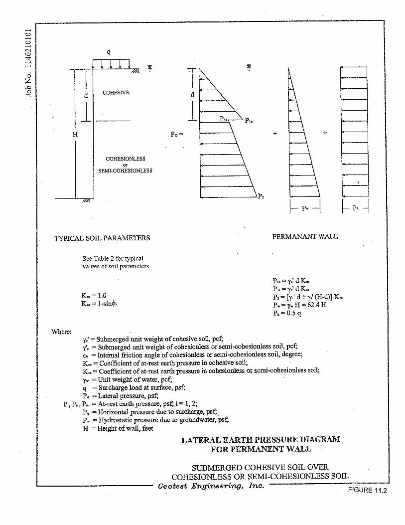
Lateral Earth Pressure. The pressure diagrams presented on Figures 5.1 through 5.3
can be used for the design of braced excavation. The lateral earth pressure diagrams
presented on Figures 11.1 through 11.3 are applicable for the design of the permanent
walls.
Hydrostatic Uplift Resistance. Structures extending below the groundwater level
should be designed to resist uplift pressure resulting from excess piezometric head.
Design uplift pressures should be computed based on the assumption that the water
table is at ground surface. To resist the hydrostatic uplift at the bottom of the
structure, one of the following sources of resistance can be utilized in each of the
designs.
a. Dead weight of structure,
b. Weight of soil above base extensions plus weight of structure, or
c. Soil-wall friction plus dead weight of structure.
The uplift force and resistance to uplift should be computed as detailed on Figure 12.
In determining the configuration and dimensions of the structure using one of the
approaches presented on Figure 12, the following factors of safety are recommended.
a. Dead weight of concrete structure, Sf1 = 1.10,
b. Weight of soil (backfill) above base extension, Sf2 = 1.5, and
c. Soil-wall friction, Sf3 = 3.0.

Geotest Engineering, Inc. Report No. 1140210101
Watonga Boulevard Paving and Drainage Improvements August 9, 2016
W. 34th
Street to W. 43rd
Street; WBS No. N-000811-0001-3
Houston, Texas
25
Friction resistance should be discounted for the upper 5 feet, since this zone is affected
by seasonal moisture changes.
5.5.4 Protection of Below Grade Structures. The design of the proper means for protection
of below grade structures will depend upon the potential of the aggressivity or corrosivity of soil and
groundwater properties. The aggressivity testing was not within the scope of this study. The design
of the protection of below grade structures is beyond the scope of services for this study.
5.5.5 Groundwater Control During Construction. Excavations for waterline and storm
sewer manhole may encounter groundwater seepage to varying degrees depending upon groundwater
conditions at the time of construction and the location and depth of excavation. Based on the soil
conditions identified in the borings, most excavations (for excavation depths shallower than 7 feet)
will be in cohesive soils. In general for cohesive soils as encountered predominantly in all the
borings for excavation depths shallower than 7 feet, groundwater (if encountered) may be managed
by collection in excavation bottom sumps for pumped disposal. However, for deeper excavations,
due to the presence of water bearing cohesionless soils at invert or within 3 to 5 feet of invert depth
at locations near borings GB-1, GB-5, GB-7, GB-8, GB-9 and GB-11, dewatering will be required.
Dewatering such as vacuum well points up to 15 feet may be required to lower the ground water
level to at least 5 feet below the bottom of excavation. The dewatering system should be pumping
well ahead of time before excavation starts so that a steady state condition (groundwater elevation at
least 5 feet below the proposed excavation bottom) is achieved. It is recommended that the actual
groundwater conditions should be verified by the contractor at the time of construction and that
groundwater control should be performed in general accordance with the City of Houston Standard
Specifications, Section 01578.
5.5.6 Structure Backfill. Excavations for the proposed structures should be backfilled in
accordance with the City of Houston Standard Specifications, Section 02316, “Excavation and
Backfill for Structures.”

Geotest Engineering, Inc. Report No. 1140210101
Watonga Boulevard Paving and Drainage Improvements August 9, 2016
W. 34th
Street to W. 43rd
Street; WBS No. N-000811-0001-3
Houston, Texas
26
5.6 16-inch Waterline Aerial Crossing Bridge
The proposed 16-inch waterline was originally planned to be supported on the existing bridge
at the Brickhouse Gully Crossing. However, in the additional scope, the proposed 16-inch waterline
will be supported on aerial crossing bridge at the Brickhouse Gully on the west side of the existing
bridge.
Based on the subsurface conditions revealed by soil borings GB-6, GB-6A, GB-7 and GB-7A,
the proposed 16-inch waterline aerial crossing bridge can be supported on drilled shafts. Design of the
bridge foundation should ensure adequate axial and lateral capacities of the foundations under
consideration. Following is a brief discussion of our method of analysis and recommendations:
5.6.1 Axial Capacity – Method of Analysis. Axial capacities of straight-sided drilled shafts
were computed using the static method of analysis as presented in the FHWA's "Drilled Shaft:
Construction Procedures and Design Methods." In the static method, the ultimate compressive
capacity, Q, for a given penetration is taken as the sum of the cumulative friction capacity, Qs, and the
end bearing capacity, Qp:
Q = Qs + Qp = fAs + qAp
Where As and Ap represent, respectively, the embedded shaft surface area and shaft tip area; f and q are
the unit skin friction and unit end bearing resistance, respectively.
Cohesive Soils. The unit skin friction, f, of a drilled shaft installed in clay at any particular
depth is a function of the undrained shear strength, Su of the clay and it is estimated using this
expression:
f = α Su
where: f = unit skin friction
α = shear strength reduction factor
Su = undrained shear strength

Geotest Engineering, Inc. Report No. 1140210101
Watonga Boulevard Paving and Drainage Improvements August 9, 2016
W. 34th
Street to W. 43rd
Street; WBS No. N-000811-0001-3
Houston, Texas
27
The shear strength reduction factor, α, for drilled shafts are discussed below.
Drilled Shafts: α = 0.55 for Su/Pa ≤ 1.5, Pa = 14.7 psi and
α = 0.55 -0.1 (Su/Pa -1.5) for 1.5 < Su/Pa ≤ 2.5, Pa = 14.7 psi
The unit end bearing, q, in clay is estimated using the expression:
q = SuNc
where: Su = undrained shear strength, and
Nc = a dimensionless bearing capacity factor; limited to 9.0 for deep
foundations
Cohesionless Soils. The unit skin friction, f, for drilled shafts driven in cohesionless soils is computed
using the following equation:
f = k σv tan c
where,
k = coefficient of lateral earth pressure, k = 0.7 for compression for drilled
shaft; and 0.5 for tension for drilled shaft
σv = effective overburden pressure
c = friction angle at interface of concrete surface and soil (use -5 )
= internal friction angle of soil
Unit end bearing, q, for cast-in-place drilled shafts driven in cohesionless soils, is computed
using the following equation:
q = Nq σv
where,
Nq = a dimensionless bearing capacity factor which is a function of , the
angle of internal friction of soil

Geotest Engineering, Inc. Report No. 1140210101
Watonga Boulevard Paving and Drainage Improvements August 9, 2016
W. 34th
Street to W. 43rd
Street; WBS No. N-000811-0001-3
Houston, Texas
28
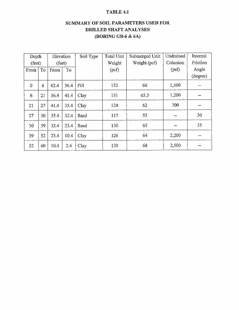
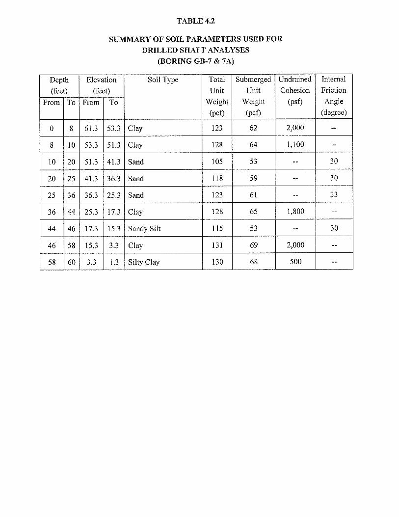
5.6.2 Allowable Axial Capacities – Drilled Shaft. Based on laboratory unconsolidated-
undrained triaxial compression tests, torvanes, and pocket penetrometers obtained from borings
GB-6, GB-6A, GB-7 and GB-7A, undrained shear strength profiles were developed and average
undrained shear strength values were used for the computation of axial shaft capacity. Summaries of
the parameters are presented in Tables 4.1 and 4.2. Using the parameters presented in these tables,
allowable axial capacities were developed for a 24-inch diameter drilled shaft for the proposed 16-
inch waterline aerial crossing bridge at the Brickhouse Gully. The developed allowable axial
capacity curves are presented on Figures 13.1 through 13.3 for 24-inch diameter shafts at abutment
and interior bents. It should be noted a factor of safety of 2.0 for skin friction and 3.0 for end bearing
were incorporated in the development of the allowable axial shaft capacities for the drilled shafts. It
should also be noted that in computing the axial capacity the contribution to axial capacity of the top
10 feet of soil has been neglected. However, if the estimated scour depth (sd) is deeper than 10 feet,
the design tip penetration determined from these capacity curves should be extended with an
additional length equal to the scour depth minus 10 feet (sd-10).
Group Effects. To minimize group effect, it is recommended that the shafts be spaced with a
minimum center–center distance of at least 3.0 times the shaft diameter.
5.6.3 Foundation Settlement. It is believed that drilled shafts designed in accordance with the
above recommendations, should experience small settlements. The settlements are generally in the
order of about 1 to 2% of shaft diameter. Differential settlements resulting from variation in subsurface
conditions and loading conditions, are also expected to be small. However, after the foundation design
is completed, the aforementioned settlement may be verified/estimated based on the final design load,
final configuration and dimension of drilled shafts, final design tip elevation, and the structural
properties of concrete, steel, etc. for drilled shafts.
5.6.4 Construction Considerations. Drilled shaft construction should follow TxDOT Standard
Specifications for Construction and Maintenance of Highways, Streets, and Bridges, 2014, Item 416.
Due to the presence of water bearing cohesionless soils encountered at the site, it is anticipated that
shaft installation will require the use of slurry displacement methods, and possible surface casing. The
surface casing is temporary and shall be retrieved as outlined in TxDOT Standard Specifications.

Geotest Engineering, Inc. Report No. 1140210101
Watonga Boulevard Paving and Drainage Improvements August 9, 2016
W. 34th
Street to W. 43rd
Street; WBS No. N-000811-0001-3
Houston, Texas
29
5.7 Traffic Signal
We understand that the existing traffic signals at W. 43rd
and Watonga Boulevard will be
replaced with new traffic signal with four new mast arm poles. Based on the subsurface conditions
revealed by borings GB-11 and GB-12 the traffic signal foundation may be supported on drilled and
underreamed footing (drilled pier). The drilled piers should be placed at a depth of at least 10 feet
below the existing grade into the stiff to hard lean clay soils and sized based on a net allowable
bearing pressure of 2,250 psf for total dead and live loads, or 1,500 psf for dead and sustained live
loads, whichever results in a larger footing area. These net allowable bearing pressures include a
factor of safety of 2.0 for total dead and live loads and 3.0 for dead and sustained live loads,
respectively.
It is our opinion that the bell to shaft diameter ratio be limited to 2.5:1. If designed bell sizes
cannot be achieved due to sloughing or cave-in during construction, the bell to shaft diameter ratio
should be reduced to less than 2:1 or straight shafts may be used.
Allowable resistance to overturning moments for drilled and underreamed footings may
be computed using the design equations provided on Figure 14. Reinforcing steel to resist uplift
load may be designed for a 31d kips, where ‘d’ is diameter of shaft.
It is recommended that an experienced soils engineer or technician be present to monitor the
drilled pier or drilled shaft foundation construction. The objectives would be (a) to ensure that
footing has been constructed to the specified dimension and is placed at the correct depth into
appropriate stratum with adequate bearing capacity as recommended in this report, (b) the footing is
concentric to the pier shaft or column, (c) the loose cutting and any soft compressible materials have
been removed from the bottom of the excavation and (d) the ability to provide immediate on-site
recommendations, should unexpected foundation construction conditions occur.
` The installation of drilled shaft, where utilized, should be carried out in accordance with City
of Houston Standard Specification No. 02465, “Drilled Shaft Foundations.”
Geotest Engineering, Inc. Report No. 1140210101
Watonga Boulevard Paving and Drainage Improvements August 9, 2016
W. 34th
Street to W. 43rd
Street; WBS No. N-000811-0001-3
Houston, Texas
30
Placement of concrete in the drilled footing should be accomplished as soon as possible after
excavation to prevent change in the state of stress and caving of the foundation soils in the shaft
bottom. No footing should be poured without the prior approval of the project engineer, architect, or
owner’s representatives.
5.8 Pavement Structure Design
It is understood that approximately 5,400 linear feet of existing pavement along Watonga
Boulevard between W. 34th
Street and W. 43rd
Street will be reconstructed with a rigid pavement.
The pavement design presented below was developed in accordance with “AASHTO Guide for
Design of Pavement Structures,” 1993 Edition.
5.8.1 Design Parameters
Subgrade Soil Properties. CBR tests were not within the scope of this project.
Therefore, resilient soil modulus is estimated based on physical properties and
strength characteristics of the natural subgrade soils. Based on the physical
properties and strength characteristics of the natural subgrade soils obtained from
laboratory tests, the effective roadbed soil resilient modulus (MR) is estimated to be
about 4,118 psi. Based on the estimated resilient modulus of the 8-inch lime-
stabilized subgrade, the effective modulus of subgrade reaction (k) is estimated to be
about 79 pci.
Traffic Data. A traffic loading of 42.8 x 10⁶ – 18-kip ESALs over 50 year design
period was utilized for the design of the pavement along Watonga Boulevard
between 34th
and 43rd
Street. This traffic loading is estimated based on a daily traffic
volume of 6,364 vehicles at 3700 Watonga Boulevard at Lamonte Lane and Railroad
(Site: RR T-244 5726) from a seven day count conducted in 2013 obtained from the
City of Houston GIMS website. This volume is projected to 2016 based on an
assumed growth rate of 2.0%. A distribution of 95% passenger cars and 5%
heavy trucks were assumed for the project alignment.

Geotest Engineering, Inc. Report No. 1140210101
Watonga Boulevard Paving and Drainage Improvements August 9, 2016
W. 34th
Street to W. 43rd
Street; WBS No. N-000811-0001-3
Houston, Texas
31
Rigid Pavement:
Other Design Parameters. Other design parameters used in the development of rigid
pavement thickness are given below:
Material Properties of Concrete:
Modulus of Elasticity of Concrete (Ec): 3,604,996 psi
Mean value of Modulus of Rupture of Concrete after 28 days
(S’c): 630 psi (based on compressive strength of 4,000 psi)
Load Transfer coefficient (J): 2.7
Drainage coefficient (Cd): 1.2
Overall Standard Deviation (So): 0.35
Reliability Level (R): 95%
Serviceability Index
Initial (Po): 4.5
Terminal (Pt): 2.50
Reinforcement Variables
Allowable Working Stress (fs): 45,000 psi (grade 60 steel)
Friction Factor (F): 1.8
Flexible Pavement:
Overall Standard Deviation (So): 0.45
Reliability Level (R): 95%
Serviceability Index
Initial (Po): 4.2
Terminal (Pt): 2.25
Layer, coefficient:
a1, a2, a3 = layer coefficient for surface, base and subbase course,
respectively. Values of the layer coefficient for each pavement
material are as follows:
a1 = 0.44 for HMHL asphalt concrete surface

Geotest Engineering, Inc. Report No. 1140210101
Watonga Boulevard Paving and Drainage Improvements August 9, 2016
W. 34th
Street to W. 43rd
Street; WBS No. N-000811-0001-3
Houston, Texas
32
a2 = 0.34 for Asphalt concrete black base
= 0.23 for Cement stabilized base
= 0.17 for lime and flyash stabilized base
a3 = 0.11 for Lime stabilized soils
Drainage coefficient:
m2, m3 = Drainage coefficient for base and subbase layers; m2 = 1.15
and m3 = 1.15 (based on a fair quality of drainage)
5.8.2 Recommended Pavement Section
Based on the design parameters described above and the AASHTO design procedures, the
thickness of rigid pavement was determined. The recommended pavement section for 50 year design
life is given below:
50 Year Life Pavement Section
Pavement Course Thickness, inches
Reinforced Concrete 12
6% Lime-stabilized subgrade 8
Based on the reinforcement variables and recommended pavement section, the required
longitudinal and transverse reinforcing steel (No. 4, Grade 60 Steel) can be determined for 12-inch
concrete pavement per Table 1 of City of Houston Drawing No. 02751-01 (Revised July 1, 2009).
Temporary Pavement Section
The flexible pavement section given below may be utilized for the temporary pavement
during construction period for the detour.
Pavement Course Thickness, inches
HMAC Surface 2
Asphalt Concrete Base 6

Geotest Engineering, Inc. Report No. 1140210101
Watonga Boulevard Paving and Drainage Improvements August 9, 2016
W. 34th
Street to W. 43rd
Street; WBS No. N-000811-0001-3
Houston, Texas
33
Transition Pavement Section
Based on the information provided to us, a transition pavement will be constructed at the
intersection of Tulsa and Watonga. No pavement cores can be obtained nor any as built drawings
were available to us to determine the existing pavement thickness along Tulsa.
Traffic Data. No traffic volume data is provided to us nor any traffic count data could be
obtained from the City of Houston GIMS website for traffic using Tulsa Road. Therefore, an
average daily volume of 1,800 is assumed. A traffic loading of 0.25 x 10⁶ 18-Kip ESALs over a 20-
year design period was utilized for the design of the flexible transition pavement section, assuming
Tulsa Road to be a commercial street with 98.5% passenger cars, 1% buses and 0.5% heavy trucks.
The flexible pavement section given below may be utilized for the transition pavement at
Tulsa Road provided that the existing pavement is thinner than the section provided below.
Pavement Course Thickness, inches
HMAC Surface 2
Asphalt Base 6
Lime Stabilized Subgrade 8
5.8.3 Preparation of Pavement Subgrade
Based on the field and laboratory test data, the subgrade soils below the existing pavement
along the project alignment consist of slight to high plasticity fat clay, lean clay and sandy lean clay.
The soils have slight to high volume change potential. Hence, lime stabilization of the clay subgrade
soils will be required to reduce the swelling and shrinkage potential of clay subgrade soils to
accelerate the construction and provide a stable subgrade on which to construct the pavement
section. The subgrade soils should be stabilized with approximately 6 percent lime (by dry unit
weight of soil) to a depth of at least 8 inches. This corresponds to approximately 40 pounds of
hydrated lime per square yard based upon a soil dry unit weight of 111 pcf. It should be noted that
quantity of lime was calculated based on the dry unit weight determined from the specific boring
Geotest Engineering, Inc. Report No. 1140210101
Watonga Boulevard Paving and Drainage Improvements August 9, 2016
W. 34th
Street to W. 43rd
Street; WBS No. N-000811-0001-3
Houston, Texas
34
locations only. The actual percentages of lime should be confirmed by laboratory tests at the time of
construction.
Subgrade preparation for the proposed pavement after removing the existing pavement
should consist of stripping, proof-rolling, and stabilization. The following procedures for subgrade
preparation are recommended:
1. Strip the surficial soils to a suitable depth to remove all surficial vegetation and
achieve grade. In isolated areas where soft, compressible, or very loose soils are
encountered, additional stripping may be required. Stripping should extend to a
minimum of 2 feet in the adjacent open (unpaved) area, where it exists beyond the
edge of the proposed pavement.
2. After stripping, the exposed surface should be proof-rolled with a minimum of 3
passes of a 30-ton pneumatic-tired roller or a partially loaded truck utilizing a tire
pressure of approximately 90 psi. If rutting develops, the tire pressure should be
reduced. The purpose of the proof-rolling operation is to identify any underlying
zones or pockets of soft soils so these weak materials can be removed and replaced.
3. Lime stabilization of cohesive subgrade should be performed in accordance with
City of Houston Standard Specification No. 02336, “Lime-Stabilized Subgrade.”
Geotest Engineering, Inc. Report No. 1140210101
Watonga Boulevard Paving and Drainage Improvements August 9, 2016
W. 34th
Street to W. 43rd
Street; WBS No. N-000811-0001-3
Houston, Texas
35
6.0 CONSTRUCTION CONSIDERATIONS
6.1 Groundwater Control
Excavations for waterline and storm sewer lines may encounter groundwater seepage to
varying degrees depending upon groundwater conditions at the time of construction and the location
and depth of excavation. Based on the soil conditions identified in the borings, all excavations (for
excavation depths shallower than 7 feet) will be in cohesive soils. In general for cohesive soils as
encountered in all the borings for excavation depths shallower than 7 feet, groundwater (if
encountered) may be managed by collection in excavation bottom sumps for pumped disposal.
However, for deeper excavations, due to the presence of water bearing cohesionless soils at invert or
within 3 feet of invert depth in borings GB-1, GB-5, GB-7, GB-8, GB-9 and GB-11, dewatering will
be required. Dewatering such as vacuum well points up to 15 feet may be required to lower the
ground water level to at least 5 feet below the bottom of excavation. The dewatering system should
be pumping well ahead of time before excavation starts so that a steady state condition (groundwater
elevation at least 5 feet below the proposed excavation bottom) is achieved. It is recommended that
the actual groundwater conditions should be verified by the contractor at the time of construction and
that groundwater control should be performed in general accordance with the City of Houston
Standard Specifications, Section 01578.

Geotest Engineering, Inc. Report No. 1140210101
Watonga Boulevard Paving and Drainage Improvements August 9, 2016
W. 34th
Street to W. 43rd
Street; WBS No. N-000811-0001-3
Houston, Texas
36
7.0 LIMITATIONS
The description of subsurface conditions and the design information contained in this report are
based on the soil borings made at the time of drilling at specific locations. However, some variation in
soil conditions may occur between soil borings. Should any subsurface conditions other than those
described in our boring logs be encountered, Geotest should be immediately notified so that further
investigation and supplemental recommendations can be provided. The depth of the groundwater level
may vary with changes in environmental conditions such as frequency and magnitude of rainfall. The
stratification lines on the log of borings represent the approximate boundaries between soil types,
however, the transition between soil types may be more gradual than depicted.
This report has been prepared for the exclusive use of City of Houston, Texas, and IDC, Inc.
for the Watonga Boulevard Paving and Drainage Improvements project. This report shall not be
reproduced without the written permission of Geotest Engineering, Inc., the City of Houston or IDC,
Inc.