geotechnical investigation report - mcgill street
TRANSCRIPT

Geotechnical Investigation Report - McGill Street Retaining Wall at Mill Creek
Hawkesbury, ON
Prepared for: Town of Hawkesbury 600 Higginson Street Hawkesbury, ON K6A 1H1
Prepared by: Stantec Consulting Ltd. 1331 Clyde Avenue Ottawa, ON K2C 3G4
Project No. 121622735
October 2019
DRAFT

GEOTECHNICAL INVESTIGATION REPORT - MCGILL STREET RETAINING WALL AT MILL CREEK October 2019
i
Table of Contents
1.0 INTRODUCTION ............................................................................................................. 1
2.0 BACKGROUND .............................................................................................................. 1
3.0 SCOPE OF WORK ........................................................................................................... 2
4.0 METHOD OF INVESTIGATION ........................................................................................ 2 4.1 SURVEYING .................................................................................................................... 3 4.2 LABORATORY TESTING .................................................................................................. 3
5.0 RESULTS OF INVESTIGATION .......................................................................................... 3 5.1 SITE RECONNAISSANCE ................................................................................................ 3 5.2 SUBSURFACE INFORMATION ........................................................................................ 4
5.2.1 Asphalt ......................................................................................................... 4 5.2.2 Fill .................................................................................................................. 4 5.2.3 Silty Sand ...................................................................................................... 4 5.2.4 Till .................................................................................................................. 5 5.2.5 Bedrock ....................................................................................................... 5
5.3 GROUNDWATER ............................................................................................................ 5
6.0 DISCUSSION AND RECOMMENDATIONS ..................................................................... 6 6.1 GEOTECHNICAL ASSESSMENT ...................................................................................... 6 6.2 GEOTECHNICAL DESIGN PARAMETERS ....................................................................... 7 6.3 LATERAL EARTH PRESSURE ............................................................................................ 8
6.3.1 Earth Pressure Design .................................................................................. 8 6.3.2 Seismic Lateral Earth Pressures ................................................................... 8
6.4 FOUNDATION RECOMMENDATION ............................................................................. 9 6.4.1 Geotechnical Resistances ......................................................................... 9 6.4.2 Geotechnical Horizontal Resistance (Sliding) .........................................10
6.5 BACKFILL .......................................................................................................................10 6.6 EROSION PROTECTION ................................................................................................11 6.7 EXCAVATION ...............................................................................................................11 6.8 FROST PROTECTION .....................................................................................................11 6.9 GROUNDWATER ...........................................................................................................11 6.10 VIBRATION MONITORING AND PRE-CONSTRUCTION SURVEYS ................................12 6.11 ADVERSE WEATHER CONDITIONS ...............................................................................13
7.0 CLOSURE ...................................................................................................................... 14
DRAFT

GEOTECHNICAL INVESTIGATION REPORT - MCGILL STREET RETAINING WALL AT MILL CREEK October 2019
ii
LIST OF TABLES Table 6.1: Comparison of Retaining Wall Rehabilitation and Replacement Options ....... 6 Table 6.2: Geotechnical Parameters .................................................................................... 7 Table 6.3: Design Parameters for Proposed Retaining Wall ................................................ 8 Table 6.4: Seismic Characteristic Parameters to Estimate Lateral Earth Pressures ............ 9 Table 6.5: Seismic Earth Pressure Parameters ....................................................................... 9 Table 6.6: Geotechnical Resistance for Proposed Retaining Wall ..................................... 9 Table 6.7: Estimates of Percolation Time and Coefficients of Permeability ......................12 Table 6.8: Suggested Peak Vibration Limits of Nearby Structures/Services .......................12
LIST OF APPENDICES
APPENDIX A Statement of General Conditions
APPENDIX B Drawing No. 1 – Key Plan Drawing No. 2 – Borehole Location Plan
APPENDIX C Symbols and Terms Used on Borehole and Test Pit Records Borehole Records Site Photographs Town of Hawkesbury McGill Street Retaining Wall Contract 1413/B
APPENDIX D Laboratory Test Results
APPENDIX E Preliminary Wall Section
APPENDIX F NBC Seismic Hazard CalculationDRAFT

GEOTECHNICAL INVESTIGATION REPORT - MCGILL STREET RETAINING WALL AT MILL CREEK October 2019
1
1.0 INTRODUCTION
This report presents the results of the Geotechnical Investigation at the McGill Street Retaining Wall at Mill Creek in Hawkesbury, Ontario. The location of the site is shown on the Key Plan, Drawing No. 1 in Appendix B.
The work was carried out in general accordance with Stantec Consulting Ltd. (Stantec) proposal dated April 26, 2019.
Limitations associated with the contents of this report are provided in the Statement of General Conditions included in Appendix A.
2.0 BACKGROUND
The Town of Hawkesbury (Town) identified a poor preforming retaining wall located on the west side of McGill Street at Mill Creek, immediately south of the intersection with Main Street. The retaining wall is a rubble stone retaining wall, which is showing signs of distress. The construction history and design of the wall is unknown, no background documents on the origin of the retaining wall are available.
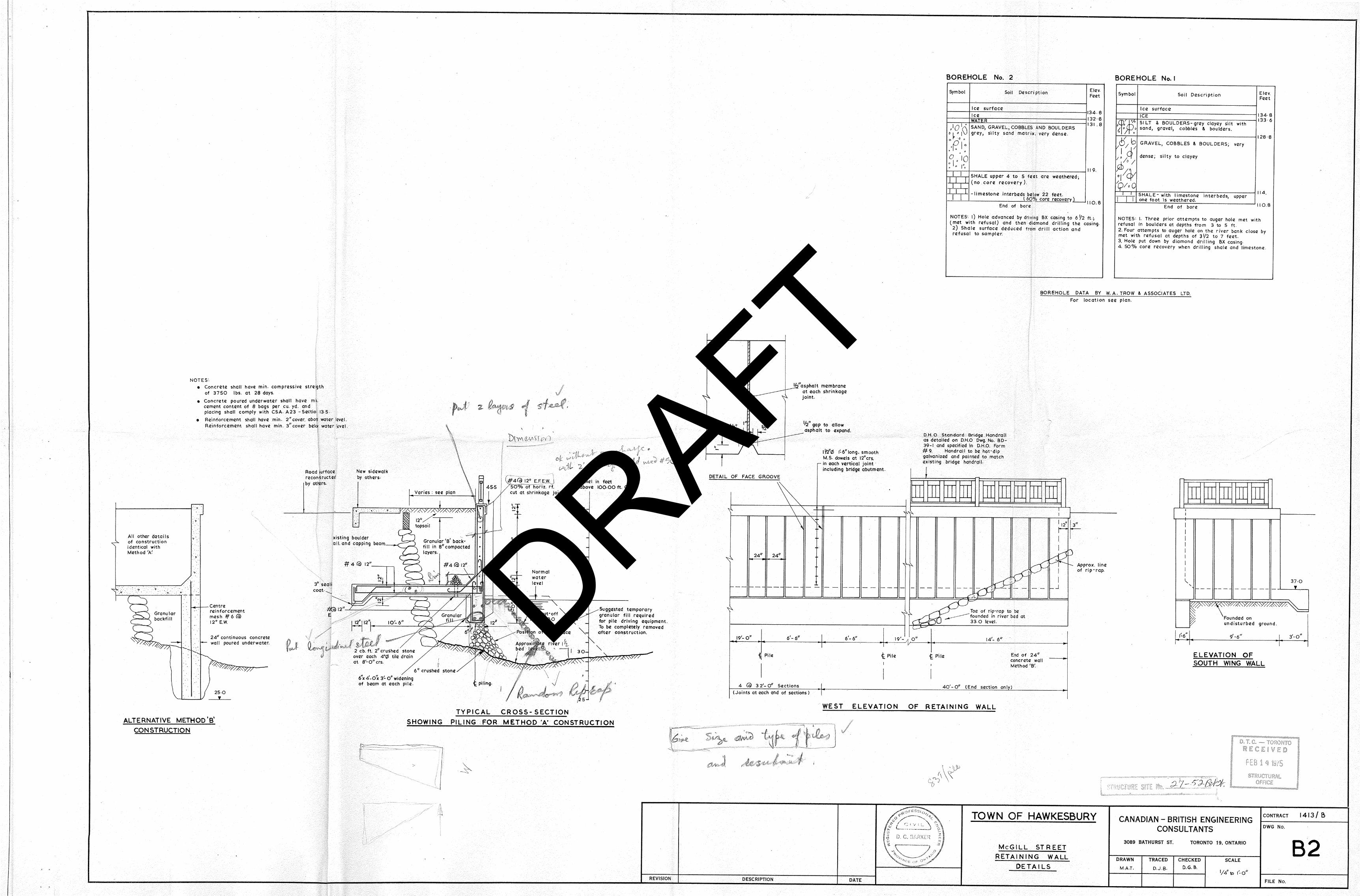
A search of the Town’s archives was carried out that found a set of contract drawings titled “Town of Hawkesbury McGill Street Retaining Wall Contract 1413/B” dated May 1964, which show the proposed construction of a new concrete retaining wall. The contract drawings are provided in Appendix C. The proposed alignment of the new wall was planned about 1 to 2 m away from the rubble stone retaining wall and toward the creek. The drawings present two boreholes records by W.A. Trow and Associates Ltd. (Trow), which were drilled at the north and south ends of the wall at the creek level. The boreholes encountered a layer of sand, gravel, cobbles and boulders extending to shale bedrock at elevation 36.3 m and 34.7 m. The drawings also indicate sewer outfall is located near the south end of the stone rubble retaining wall.
General Site Description
The retaining wall is inferred to be 3 to 5 m high and 50 m long. The exposed face of the retaining wall is about 3 m high and the submerged height of the wall is unknown, however the depth of Mill Creek is inferred to be about 1 to 2 m (normal creek water level). The visible section of the retaining wall consists of sub rounded rubble stones generally less than 0.8 m in diameter and no mortar/cement is visible between the stones. The top of the rubble stones is capped with concrete.
A chain link fence and guide rail are parallel to the top of the wall.
McGill Street is a two-lane road with a west bound turning lane and east bound merge lane with Main Street. Several utilities are buried within McGill Street such as a 100 mm diameter gas main, sewers and a water main.
DRAFT

GEOTECHNICAL INVESTIGATION REPORT - MCGILL STREET RETAINING WALL AT MILL CREEK October 2019
2
Physiographic Description
Based on available geological mapping of the area the following subsurface conditions are anticipated in the vicinity of the site:
• According to the Physiography of the Eastern Portion of Southern Ontario by Chapman and Putnam, the site is in a zone of sand planes and till planes.
• The drift thickness at the site ranges from about 0 to 6 m according to the Ontario Division of Mines Drift Thickness Series, Hawkesbury – Lachute Area.
• The bedrock in the vicinity of the site is interbedded quartz sandstone, shaly limestone, and shale of the Rockcliffe Formation (Ontario Geological Survey, Hawkesbury – Lachute Area Map p.2718).
Topography
The normal stage elevation of the creek is several meters lower than McGill Street. The ground surface behind the retaining wall, McGill Street, is generally flat with a gentle slope toward the south from Main Street.
3.0 SCOPE OF WORK
The scope of work for this Geotechnical Investigation included the following:
• Site reconnaissance to observe the condition of the retaining wall; • Advance one (1) borehole behind the retaining wall to a depth of 8 m below ground
surface or refusal, if shallower; • Standard Penetration Tests (SPT) at regular intervals in the boreholes to collect soil samples; • A geotechnical laboratory testing program to characterize the soil; • Prepare a Geotechnical Investigation report with geotechnical engineering
recommendations on options to stabilize or replace the wall.
4.0 METHOD OF INVESTIGATION
Stantec arranged to have the borehole locations cleared of both private and public underground utilities prior to drilling. It was originally planned to drill the borehole behind the retaining wall in south bound lane of McGill Street, however due the location of buried utilities such as gas and water the location of the borehole was relocated to the parking lot on the west side of McGill Street.
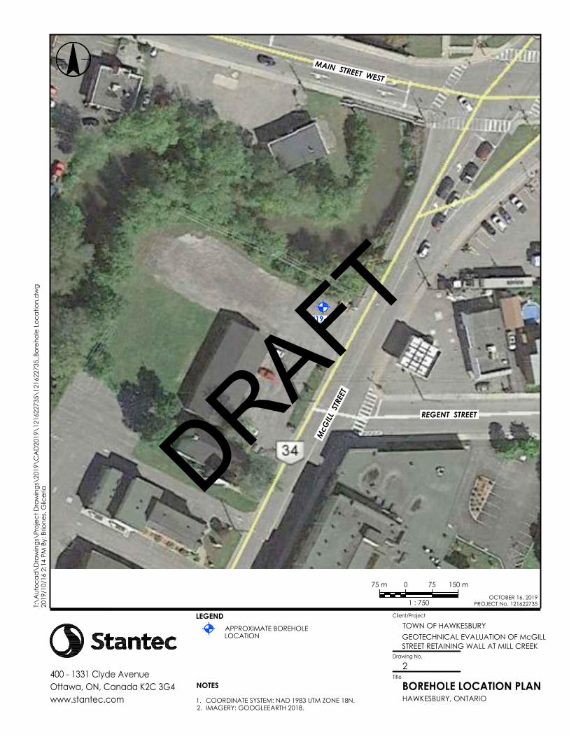
The field drilling program was carried out on August 20, 2019. Boreholes BH19-01 was drilled at the location shown on the Borehole Location Plan, Drawing No. 2 in Appendix B.
The borehole was advanced using a truck mounted CME drill rig equipped for soil sampling. The subsurface stratigraphy encountered in each borehole was recorded in the field by experienced Stantec personnel while performing Standard Penetration Tests (SPT). Split spoon
DRAFT

GEOTECHNICAL INVESTIGATION REPORT - MCGILL STREET RETAINING WALL AT MILL CREEK October 2019
3
samples were collected continuously until the termination of the boreholes. The borehole was backfilled with auger cuttings and cold patch asphalt at surface. All recovered soil samples were stored in moisture-proof bags and returned to the Stantec Ottawa Laboratory for further classification and testing.
4.1 SURVEYING
The borehole was in the northeast corner of the parking lot to civic address 20 Main Street. The location shown on the Borehole Location Plan, Drawing No. 2 in Appendix B.
4.2 LABORATORY TESTING
All samples returned to the laboratory were subjected to detailed visual examination and classification by a geotechnical engineer. Moisture content determination was conducted on all soil samples and select soil samples were also submitted for grain size analysis. The results of the laboratory tests are provided in the Borehole Records in Appendix C, and the figures included in Appendix D. The samples will be stored for a period of one (1) month after the issuance of this report, unless otherwise directed by the client.
5.0 RESULTS OF INVESTIGATION
The following sections summarize the result of the investigation.
5.1 SITE RECONNAISSANCE
A site visit was carried out by Stantec on June 14, 2019, to observe the condition of the retaining wall. Site photographs collected during the visit are presented in Appendix C, and the site observations are summarized below:
• The exposed face of the retaining wall was about 3 m high. • The visible section of the retaining wall consisted of sub rounded rubble stones generally less
than 0.8 m in diameter with no mortar/cement visible between the stones. The top of the rubble stones was capped with concrete.
• The concrete cap above the rubble stones was in a poor condition, several vertical cracks were visible. A large segment of the concrete cap was displaced from the wall and the rubble stones are displaced toward the creek.
• Ponding water was noted along the west curb of McGill Street. The location of the water appears to coincide with the location where the concrete cap is displaced.
• A large concrete block was visible on the face of the retaining wall, the concrete block was located near the Main Street West Bridge.
• The chain link fence was in a poor, several of the posts and top bars are bent. • The guide rail at the top of the retaining wall was in a fair condition, no distresses were
observed.
DRAFT

GEOTECHNICAL INVESTIGATION REPORT - MCGILL STREET RETAINING WALL AT MILL CREEK October 2019
4
5.2 SUBSURFACE INFORMATION
In general, the subsurface profile at the site consists of asphalt and fill material, over a layer of silty sand underlain by a silty sand with gravel till deposit.
The subsurface conditions and results of the laboratory tests performed on soil samples are presented in the Borehole Records provided in Appendix C. An explanation of the symbols and terms used in the Borehole Records is also provided.
A summary of the observed subsurface conditions is provided below.
5.2.1 Asphalt
A 40 mm thick layer of asphalt was encountered at ground surface.
5.2.2 Fill
Fill was encountered beneath the asphalt layer, the thickness of the fill was 1.8 m. The fill encountered consisted of silty sand with varying amounts of gravel and trace clay. Debris including brick and rock pieces was noted at a depth of 1.5 m.
The SPT ‘N’ values varied from 5 to greater than 50 indicating a loose to very dense compactness.
The moisture content ranged from 8% to 10%.
One representative sample of the fill was chosen for grain size analysis; the results are summarized below. The grain size distribution curve is shown on Figure No. 1 Appendix D.
• Gravel: 20% • Sand: 50% • Clay and Silt sized particles: 30%
According to the Unified Soil Classification System (USCS), the soil can be classified as silty sand with gravel.
5.2.3 Silty Sand
A layer of silty sand was encountered beneath the fill, the thickness of the silty sand layer was 1.5 m and consisted of black to brown silty sand with varying amounts of gravel and occasional cobbles.
The SPT ‘N’ value was 8 indicating a loose compactness.
The moisture content ranged from 13% to 25%.
DRAFT
GEOTECHNICAL INVESTIGATION REPORT - MCGILL STREET RETAINING WALL AT MILL CREEK October 2019
5
One representative sample of the sand was chosen for grain size analysis; the results are summarized below. The grain size distribution curves are shown on Figure No. 2 Appendix D.
• Gravel: 22% • Sand: 44% • Silt: 26% • Clay: 8%
According to the USCS, the soil can be classified as silty sand with gravel.
5.2.4 Till
A till deposit was encountered beneath the layer of silty sand, the thickness of the till was 0.7 m, the borehole was terminated on refusal within the till layer. The till consisted of silty sand with gravel and frequent rock pieces.
The SPT ‘N’ values varied from 43 to greater than 50 indicating a dense to very dense compactness.
The moisture content ranged from 6% to 8%.
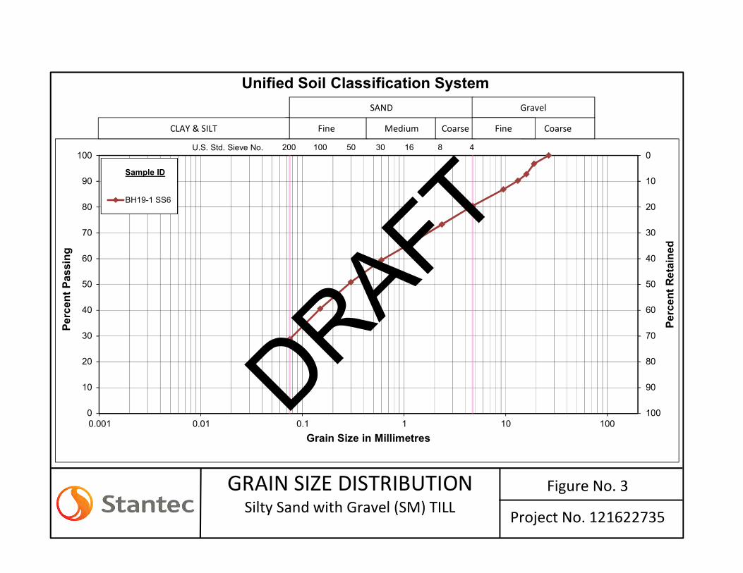
One representative sample of the sand was chosen for grain size analysis; the results are summarized below. The grain size distribution curves are shown on Figure No. 3 Appendix D.
• Gravel: 19% • Sand: 52% • Clay and Silt sized particles: 29%
According to the USCS, the soil can be classified as silty sand with gravel.
5.2.5 Bedrock
Auger refusal was encountered at a depth of 4.1 m on inferred bedrock or cobbles and boulders.
The Trow boreholes, presented on the 1964 Contract Drawings, encountered bedrock at approximate elevation 36.3 m and 34.7 m
5.3 GROUNDWATER
The soil samples in the borehole were observed to wet below a 2 m depth, the groundwater level is likely about 2 m below grade, however the groundwater level will change in response to changes in the water level in the creek.
The 1964 Contract Drawings indicate a normal water depth of 1.8 m in the creek.
Fluctuations in the groundwater level should be anticipated, due to seasonal variations or in response to a precipitation event and the water level in the creek.
DRAFT

GEOTECHNICAL INVESTIGATION REPORT - MCGILL STREET RETAINING WALL AT MILL CREEK October 2019
6
6.0 DISCUSSION AND RECOMMENDATIONS
The following sections summarize the geotechnical assessment of the existing retaining wall, review of rehabilitation/replacement options for the retaining wall and geotechnical recommendations for the design and construction of a new retaining wall.
6.1 GEOTECHNICAL ASSESSMENT
The observed distresses in the retaining wall such as the cracks in the concrete cap and displaced rubble stones, suggest rotational sliding of the wall occurred. It is our opinion that the retaining wall is unstable, particularly at the location where the rotational sliding occurred. We recommend rehabbing/replacing the wall, the work should be carried out within 24 months.
The observed distresses in the retaining wall do not suggest a failure of the wall is imminent, however changes to the site conditions such as an earthquake or erosion of the toe could trigger additional movement and/or failure. We recommend bi-monthly monitoring of the wall. If changes in the condition of face of the retaining wall, concrete cap and ground surface behind the wall are observed a geotechnical engineer should be contacted to assess the retaining wall.
The following table presents several rehabilitation and replacement options for the retaining wall, advantages, disadvantages, risks and relative cost and ranking for each option.
Table 6.1: Comparison of Retaining Wall Rehabilitation and Replacement Options
Option Advantages Disadvantages Relative Cost Risk Ranking
1-Refurbish Resurface the wall face with concrete
• Least intrusive option
• Reduces excavation into McGill Street
• Reduces traffic impacts
• Short-term solution, spalling of concrete.
• Long-term performance of wall anticipated to be poor
Low to medium
• Long-term performance
• Poor bonding between concrete and rubble stones
3
2-Sheet Piles Install sheet piles behind the wall
• Reduces excavation into McGill Street
• Option may require installing tie-back anchors
• Alignment of sheet piles may encroach into McGill Street
medium • Obstruction causing shallow refusal of sheet piles
4
3-Gabion Wall Replace the wall with a gabion basket wall
• Aesthetic consistent with existing wall
• Simple wall construction
• Excavation for wall will extend into McGill Street
• Traffic disruptions • Long-term
performance of gabion baskets due to ice loading
High • Deformation of gabion basket from ice loads
2
DRAFT

GEOTECHNICAL INVESTIGATION REPORT - MCGILL STREET RETAINING WALL AT MILL CREEK October 2019
7
Option Advantages Disadvantages Relative Cost Risk Ranking
4-Manufacture Wall System Replace the wall with interlocking wall system such as Redi-Rock or equivalent
• Simple wall construction
• Commonly used materials
• Long-term performance
• Excavation for wall will extend into McGill Street
• Traffic disruptions
High • Dewatering of subgrade for base block
1
Consideration was also given to placing additional rip-rap against the face of the wall. It was concluded that is not feasible due to the encroachment of the rip-rap into the creek and potential impacts to the hydraulics of the creek.
It is our opinion that Option 4, replace the exiting wall with a Redi-Rock wall or equivalent is the preferred option. A preliminary wall section for 4.27 m high wall is presented in Appendix E. The preliminary wall section is only for conceptual planning and not intended for detailed design. The detailed design of the wall will need to include armor stone at the toe to prevent scour, additional backfill behind the wall for drainage and a gravity drain above the normal water level in the creek.
6.2 GEOTECHNICAL DESIGN PARAMETERS
The subsurface conditions encountered in the boreholes are provided on the Borehole Record in Appendix B. An explanation of the symbols and terms used in the Borehole Record is also included in Appendix B for reference.
Table 6.2: Geotechnical Parameters Depth Below Grade (m) Soil Type
Design Parameters1
From To γ φ E
0 2 FILL: Brown silty sand (SM) 20 30 20
2 3.5 Loose black-brown silty sand (SM) with gravel 20 30 15
3.5 9.5 TILL: Very dense brown clayey sand (SC) to silty sand (SM) with gravel 21 33 100
9.5 varies Inferred Bedrock 26 - -
Notes: (1) γ = total unit weight (kN/m3), φ = soil friction angle (°) and E = soil modulus (MPa).
(2) Groundwater will be assumed to be at the level of the creek for design purposes.
DRAFT

GEOTECHNICAL INVESTIGATION REPORT - MCGILL STREET RETAINING WALL AT MILL CREEK October 2019
8
6.3 LATERAL EARTH PRESSURE
6.3.1 Earth Pressure Design
Table 6.3 provides soil parameters to be used for the design of the retaining wall; the parameters assume a horizontal backslope.
Table 6.3: Design Parameters for Proposed Retaining Wall Parameters OPSS Granular
A OPSS Granular B
Type I
Unit Weight (kN/m3) 22.0 21.0
Angle of Internal Friction, ɸ 35° 32°
Coefficient of Active Earth Pressure, Ka (Horizontal Backslope) 0.27 0.31
Coefficient of Passive Earth Pressure, Kp (Horizontal Backslope) 3.69 3.25
For analysis, the total thrusts due to earth pressure can be calculated using the following equations:
𝑃𝑃𝐴𝐴 = ½ 𝐾𝐾𝑎𝑎 𝛾𝛾 𝐻𝐻2
𝑃𝑃𝑃𝑃 = ½ 𝐾𝐾𝑝𝑝 𝛾𝛾 𝐻𝐻2
Where 𝐾𝐾𝑎𝑎 and 𝐾𝐾𝑝𝑝 are the earth pressure coefficients corresponding to active and passive conditions, respectively, and 𝑃𝑃𝐴𝐴 and 𝑃𝑃𝑃𝑃 are the corresponding thrusts. 𝐻𝐻 is the height of the wall upon which active and/or passive thrusts are acting. The values of 𝐾𝐾𝑎𝑎 and 𝐾𝐾𝑝𝑝 along with the soil unit weight 𝛾𝛾 are given in Table 6.3. The thrust typically acts at a point one-third up the height of the wall; however, the wall type and material will dictate the actual pressure distribution.
6.3.2 Seismic Lateral Earth Pressures
The retaining wall should also be designed to resist the earth pressures induced under seismic loading conditions.
The total active and passive thrusts under seismic loading conditions can be calculated using the following equations:
PAE = ½ KAE γ H2 (1 - kV)
PPE = ½ KPE γ H2 (1 - kV) – not applicable
where:
KAE = active earth pressure coefficient (combined static and seismic)
KPE = passive earth pressure coefficient (combined static and seismic) – not applicable
H = height of wall
DRAFT

GEOTECHNICAL INVESTIGATION REPORT - MCGILL STREET RETAINING WALL AT MILL CREEK October 2019
9
kh = horizontal acceleration coefficient
kv = vertical acceleration coefficient
γ = total unit weight
For this site, the characteristic parameters provided below in Table 6.4 were used to develop the recommended KAE values in accordance with CHBDC 2014. KPE is not applicable to design of the retaining wall, soil below the frost penetration depth is not present in front of the wall.
Table 6.4: Seismic Characteristic Parameters to Estimate Lateral Earth Pressures
Site Adjusted 𝑷𝑷𝑷𝑷𝑷𝑷 Horizontal Acceleration Coefficient, kho Horizontal Acceleration Coefficient, kh
Non-Yielding Yielding > 25 𝑚𝑚𝑚𝑚
0.327g 0.3270 0.1635
Note: kho is the seismic horizontal acceleration coefficient that corresponds to zero wall movement and is equal to the site-adjusted 𝑷𝑷𝑷𝑷𝑷𝑷 estimated at ground surface. Vertical acceleration coefficient (kv) should be ignored in the calculations as per CHBDC 2014, section C4.6.5.
The seismic earth pressures may be calculated using the parameters provided in Table 6.5. Value assumes a horizontal backfill slope. The angle of friction between the soil and the wall has been set at 0° to provide a conservative estimate.
Table 6.5: Seismic Earth Pressure Parameters Parameters OPSS Granular A OPSS Granular B
Unit Weight (kN/m3) 22 21.0
Angle of Internal Friction, ɸ 35° 32°
Wall type: (a) yielding; (b) non-yielding (a) (b) (a) (b)
Active Earth Pressure (KAE) 0.37 0.50 0.41 0.56
Height of Application of PAE from base as a ratio of wall height (H) 0.404 0.456 0.401 0.453
6.4 FOUNDATION RECOMMENDATION
6.4.1 Geotechnical Resistances
The geotechnical resistances provided in Table 6.6 below may be used in the design for the retaining wall foundation.
Table 6.6: Geotechnical Resistance for Proposed Retaining Wall
Subgrade Soil Type
Footing Width (m)
Factored Geotechnical Resistance at ULSf (kPa)
φgu = 0.5
Factored Geotechnical Resistance at SLS (kPa)
φgs = 0.8
Till 2 to 3 235 235
DRAFT

GEOTECHNICAL INVESTIGATION REPORT - MCGILL STREET RETAINING WALL AT MILL CREEK October 2019
10
The Geotechnical Resistances were estimated assuming a consequence classification of “Typical” with a consequence factor equal to 1.0 based on Section 6.5 and Table 6.1 of the CHBDC.
In accordance with Section 6.9.1 of the CHBDC and the Typical Understanding of subsurface conditions adopted for this project, a resistance factor of 0.5 has been applied in calculating the factored geotechnical resistance at Ultimate Limit State (ULSf).
The geotechnical resistance at Serviceability Limit State (SLS) corresponds to a maximum settlement of 25 mm and incorporates a resistance factor of 0.8. For this project the ULSF resistance value governs the design.
The geotechnical resistance values provided above relate to loads applied concentric and perpendicular to the top of the walls; where applicable, inclination of the load should be considered in accordance with Section 6.10.2 of the Canadian Highway Bridge Design Code (CHBDC 2014) and its Commentary.
6.4.2 Geotechnical Horizontal Resistance (Sliding)
The unfactored horizontal resistance along the base of the retaining wall may be calculated using the following unfactored coefficients of friction:
0.55 between OPSS Granular A/Till and precast concrete
In accordance with Table 6.2 of the CHBDC, a resistance factor against sliding of 0.8 (frictional) should be applied to obtain the resistance at ULSf.
6.5 BACKFILL
The retaining wall should be backfilled with free-draining granular backfill materials and incorporate longitudinal drains and weep holes to provide positive drainage of the backfill. For the purpose of this report, it is assumed that the wall will be backfilled with either OPSS Granular B Type I or II or Granular A materials. The backfill should be placed within a wedge-shaped zone defined by a line drawn up and back from the back edge of the base of the wall at an inclination of 1 horizontal to 1 vertical (1H:1V).
Excavation and backfill for the new structures should be carried out in accordance with OPSS 902 Construction Specification for Excavation and Backfilling – Structures. Backfill materials should be placed and compacted in accordance with the requirements of OPSS.PROV 206 and OPSS.PROV 501, respectively.
DRAFT

GEOTECHNICAL INVESTIGATION REPORT - MCGILL STREET RETAINING WALL AT MILL CREEK October 2019
11
6.6 EROSION PROTECTION
Erosion protection should be placed on the reinstated side slopes to the river. Erosion protection should include the following:
• A 0.8 m thick layer (minimum) layer of rip-rap placed on the slope. • Side slope of the rip-rap should be no steeper than 1.5H:1V. • Rip-rap material should consist of well graded angular rock with a minimum diameter of 275
mm and a maximum diameter of 500 mm. Rip-rap material should be placed on a non-woven geotextile such as Terrafix 600R.
6.7 EXCAVATION
The overburden soils near the toe of the existing retaining wall (below road grade) are mainly Type 1 soils. Open cut excavations 1.2 m or deeper must be sloped to within 1.2 m of its bottom with a slope no steeper than one horizontal to one vertical (1H:1V) for Type 1 soils. The stability of the wall of the excavation may be affected by:
• Surcharge loads • Stockpiles • Groundwater seepage conditions
6.8 FROST PROTECTION
In accordance with OPSD 3090.101, the design frost penetration depth for foundations, f, at the site is 1.8 m. Therefore, footings sensitive to movement from frost heave should be provided with a minimum of 1.8 m of soil cover or equivalent insulation for protection against frost heaving.
The wall manufacture’s minimum embedment depths for frost penetration should be followed for design.
6.9 GROUNDWATER
The proposed excavation for the retaining wall will require excavation beneath water level of Mill Creek. It is anticipated the excavations can be dewatered using a cofferdam with sump and pump techniques. High inflow rates may be encountered where excavations are carried out within high permeability zones such as the silty sand and till layers. Alternative dewatering measures may be required to cut off water seepage in these areas such as enclosing the work area with a sheet pile cofferdam advanced to refusal.
The Ontario Building Code (OBC) Supplementary Standard SB-6 Percolation Time and Soil Descriptions provide approximate relationships between the grain size analysis of soils and respective percolation time (T) and coefficient of permeability (K). Values for the hydraulic conductivity of the fill materials are not available as the inherent variability of fill materials does not provide for consistent and representative values or range in values.
DRAFT

GEOTECHNICAL INVESTIGATION REPORT - MCGILL STREET RETAINING WALL AT MILL CREEK October 2019
12
Percolation time (T) and coefficient of permeability (K) values are provided in Table 6.7 various soil layers.
Table 6.77.4: Estimates of Percolation Time and Coefficients of Permeability
Native Soil Type Estimated
Percolation Time - T (minutes/cm)
Estimated Coefficient of Permeability - K (cm/sec)
Silty Sand (SM) with gravel/Till 8 to 20 1x10⁻³ to 1x10⁻⁵
The OBC states that “Field conditions such as soil density, structure and mineralogy will influence the actual T and K values and as such an anticipated range is provided for each of the soil types encountered”. The OBC also states, in part, that “it must be emphasized that, particularly for fine grained soils, there is no consistent relationship (between coefficient of permeability and soils of various types) due to the many factors involved”. Such factors as structure, mineralogy, density (compactness or consistency), plasticity, and organic content of the soil can have a large influence on the hydraulic conductivity; variations in excess of an “order of magnitude” are commonplace in this respect.
In consideration of the limitations stated above, the values provided should be considered only as an approximation of the field conditions.
Contractors must make their own independent assessment of the soil and groundwater conditions as reported herein for purposes of assessing the need and methods of possible dewatering and/or unwatering.
Dewatering activities should be limited to less than 50,000 L/day, thus a Ministry of the Environment Permit to Take Water (PTTW) is not required for temporary groundwater dewatering of excavations.
The quality of groundwater removed during the construction activities should be assessed at that time to determine if it may be disposed of directly to the local sanitary/storm sewer without treatment, under a permit that would be required from the Town.
Stantec recommends the successful bidder submit a dewatering plan.
6.10 VIBRATION MONITORING AND PRE-CONSTRUCTION SURVEYS
The required construction activities will generate some vibrations that will be perceptible to the nearby residences. The vibrations are expected to be greatest during excavation and material placement. It is recommended that pre-construction surveys be carried out. Table 6.8 provides vibration limits intended to prevent cracking and other structural problems.
Table 6.8: Suggested Peak Vibration Limits of Nearby Structures/Services Frequency Range (Hz) <10 10 to 40 >40
Peak Particle Velocity (mm/sec) 5 5 to 50 (sliding scale) 50
DRAFT

GEOTECHNICAL INVESTIGATION REPORT - MCGILL STREET RETAINING WALL AT MILL CREEK October 2019
13
6.11 ADVERSE WEATHER CONDITIONS
Additional precautions, effort, and measures may be required, when and where construction is undertaken during late fall, winter, and early spring construction when the temperature and climatic conditions have an adverse influence on the standard construction practices or during periods of inclement weather. With respect to all earthworks activities undertaken during the late fall through to late spring, when less-than-ideal construction conditions may prevail, the following comments are provided:
• All of the engineered fill should consist of granular materials, including either the crushed rock or imported OPSS granular B or A materials. The use of non-granular fill materials may be considered, but would be extremely problematic.
• Fill placement should be inspected by qualified field personnel on a full time basis under the supervision of a geotechnical engineer, with the authority to stop the placement of fill at any time when conditions are considered to be unfavorable.
• Imported materials that contain ice, snow, or any frozen material should not be accepted for use.
• Overnight frost penetration may occur, even in granular fill materials, where precipitation and ground surface runoff pools and accumulates, and freezing temperatures exist. Any frozen materials should be removed prior to placing subsequent lifts of engineered fill. Breaking the frost in-situ is not considered acceptable.
• It may be necessary to stop the placement of engineered fill during periods of cold, where ambient temperatures are -5°C or less, exist.
• Concrete should not be placed over frozen subgrades. Once concrete is placed the subgrade must be protected from freezing.
• Footings should not be placed on frozen subgrades. The subgrades beneath footings and concrete slabs must be protected from freezing.
• The placement of engineered fill materials, grout and concrete, during cold weather conditions requires extra effort beyond that typical when better climatic conditions prevail. At any time where conditions are deemed unfavorable, the placement operation may need to be suspended.
Additional considerations for heating of concrete, heating of forms and reinforcing steel, protection of concrete from freezing, and similar measures may also be required subject to climatic conditions at the time of construction.
DRAFT

GEOTECHNICAL INVESTIGATION REPORT - MCGILL STREET RETAINING WALL AT MILL CREEK October 2019
14
7.0 CLOSURE
We trust that this memorandum meets with your requirements and encourage you to contact us should you have any questions or comments with regards to this memo.
Use of this report is subject to the Statement of General Conditions provided in Appendix A. It is the responsibility of the Town of Hawkesbury, identified as “the Client” within the Statement of General Conditions, and its agents to review the conditions and to notify Stantec Consulting Ltd. should any of these not be satisfied. The Statement of General Conditions addresses the following:
• Use of the report • Basis of the report • Standard of care • Interpretation of site conditions • Varying or unexpected site conditions • Planning, design or construction
This report has been prepared by Christopher McGrath and reviewed by Raymond Hache.
Respectfully submitted,
STANTEC CONSULTING LTD.
Chris McGrath, P.Eng. Senior Associate, Geotechnical Engineer
v:\01216\active\1216205xx\121620526\05_report_deliv\deliverables\report\121620526 rpt_final_sr_lacasse road_20170920.docx
DRAFT

GEOTECHNICAL INVESTIGATION REPORT - MCGILL STREET RETAINING WALL AT MILL CREEK October 2019
APPENDIX A Statement of General Conditions
DRAFT

STATEMENT OF GENERAL CONDITIONS USE OF THIS REPORT: This report has been prepared for the sole benefit of the Client or its agent and may not be used by any third party without the express written consent of Stantec Consulting Ltd. and the Client. Any use which a third party makes of this report is the responsibility of such third party. BASIS OF THE REPORT: The information, opinions, and/or recommendations made in this report are in accordance with Stantec Consulting Ltd.’s present understanding of the site specific project as described by the Client. The applicability of these is restricted to the site conditions encountered at the time of the investigation or study. If the proposed site specific project differs or is modified from what is described in this report or if the site conditions are altered, this report is no longer valid unless Stantec Consulting Ltd. is requested by the Client to review and revise the report to reflect the differing or modified project specifics and/or the altered site conditions. STANDARD OF CARE: Preparation of this report, and all associated work, was carried out in accordance with the normally accepted standard of care in the state or province of execution for the specific professional service provided to the Client. No other warranty is made. INTERPRETATION OF SITE CONDITIONS: Soil, rock, or other material descriptions, and statements regarding their condition, made in this report are based on site conditions encountered by Stantec Consulting Ltd. at the time of the work and at the specific testing and/or sampling locations. Classifications and statements of condition have been made in accordance with normally accepted practices which are judgmental in nature; no specific description should be considered exact, but rather reflective of the anticipated material behavior. Extrapolation of in situ conditions can only be made to some limited extent beyond the sampling or test points. The extent depends on variability of the soil, rock and groundwater conditions as influenced by geological processes, construction activity, and site use. VARYING OR UNEXPECTED CONDITIONS: Should any site or subsurface conditions be encountered that are different from those described in this report or encountered at the test locations, Stantec Consulting Ltd. must be notified immediately to assess if the varying or unexpected conditions are substantial and if reassessments of the report conclusions or recommendations are required. Stantec Consulting Ltd. will not be responsible to any party for damages incurred as a result of failing to notify Stantec Consulting Ltd. that differing site or sub-surface conditions are present upon becoming aware of such conditions. PLANNING, DESIGN, OR CONSTRUCTION: Development or design plans and specifications should be reviewed by Stantec Consulting Ltd., sufficiently ahead of initiating the next project stage (property acquisition, tender, construction, etc), to confirm that this report completely addresses the elaborated project specifics and that the contents of this report have been properly interpreted. Specialty quality assurance services (field observations and testing) during construction are a necessary part of the evaluation of sub-subsurface conditions and site preparation works. Site work relating to the recommendations included in this report should only be carried out in the presence of a qualified geotechnical engineer; Stantec Consulting Ltd. cannot be responsible for site work carried out without being present.
DRAFT

GEOTECHNICAL INVESTIGATION REPORT - MCGILL STREET RETAINING WALL AT MILL CREEK October 2019
APPENDIX B Drawing No. 1 – Key Plan
Drawing No. 2 – Borehole Location Plan
DRAFT

Drawing No.
Title
Project Location
Client/Project
_̂
Québec
Ontario
Highway 417Alfred
L'Orignal
VankleekHill
Chatham
_̂
Atlantic
Street
Roch Street
OmerStreet
SinclairStreet
AberdeenStreet
AlbertStreet
JamesStreet
NelsonStreet West
Albe
rt
Stre
et
Wes
tSt
reet
Edm
ond
Stre
et
Jam
esSt
reet
Race
Stre
et
Kipl
ing
Stre
et
GhislainStreet
James
Street
Ja m es
Stree t
MarchCrescent
Lafle cheRo ad
Theria
ult
S treet
RegentStreet
R egentS treet
Porte
lanc
eAv
enue
Wes
t Stre
et
CecileBoulevard
Ghislain Street
Laur
ier S
treet
Cat
herin
eSt
reet
Mar
y St
reet
Cha
mpl
ain
Stre
et
Stevens Street
HigginsonStreet
Wes
tSt
reet
Higginson Street
MayCrescent
RegentStreet
RegentStreet
Tach
eBo
uleva
rd
TessierStreet
IndustrielBoulevard
Mcg
illSt
reet
CountyRoad 17
Cartie
rBo
uleva
rd
SpenceAvenue
Cartie
rBou
levar
d
Cam
eron
Stre
et
Cam
eron
Stre
et
Cartie
rBou
levard
John
Stre
et
Main StreetEast
SpenceAvenue
Main Street
East
SandyHill Road
Main StreetEast
Cam
eron
Stre
et
CountyRoad 4
Mcg
illSt
reet
Cam
eron
Stre
et
Mcg
illS
t ree t
CountyRoad 4
SpenceAvenue
SpenceAvenue
Chenail
Boulevard
CountyRoad 17
Mcg
illSt
reet
Cam
eron
Stre
et
JohnStreet
SpenceAvenue
SandyHill Road
Main StreetWest
CountyRoad 17
County Road 17
Chu
rch
Richer
Laur
in
Riordon
Mar
io
Dollard
Aberdeen
Cha
rtran
d
Wat
er
Dupl
ate
Lansdowne
Smer
don
MillEntrance
Sinclair
Fauteux
Roch
Andre
Therese
Paquette
Cle
men
t
Ham
ilton
Thor
ne
Wol
fe
BelleRive
Jerome
Montc
alm
Atlantic
Rupert
Abbo
tt
Race
Ham
pden
Garneau
Nelson
Mar
ch
Alla
n
Jacynthe
Ger
ard
William
Albert
Roxane
Portelance
Lafrance
Gen
evie
ve
Kipl
ing
Pros
pect
Salis
bury
Charle
bois
Cat
herin
eLa
urie
r
Ther
iaul
t
Berth
a
Mar
y
Gor
don
Gascon
Henry
Emer
ald
Wes
t
Stevens
Cha
mpl
ain
Edm
ond
Stan
ley
Sidney
Kitc
hene
rOmer
Paul
Berthiaume
Cartie
r
May
Higginson
4
Cecile
RejaneRegent
Lafle
che
AlexanderSiversky
Pilo
n
RoyalGhislain
Tache
Parisien
BonPasteur
Jam
esChenail
34
Tessier
McG
ill
Cam
eron
John
Spence
Sandy Hill
Industriel
Main
17
High
way
34
High
way
34
Highway 34
528500
528500
529000
529000
529500
529500
530000
530000
530500
530500
531000
531000
531500
531500
5049
000
5049
000
5049
500
5049
500
5050
000
5050
000
5050
500
5050
500
5051
000
5051
000
5051
500
5051
500
5052
000
5052
000
5052
500
5052
500
($$¯
Disclaimer: Stantec assumes no responsibility for data supplied in electronic format. The recipient accepts full responsibility for verifying the accuracy and completeness of the data. The recipient releases Stantec, its officers, employees, consultants and agents, from any and all claims arising in any way from the content or provision of the data.
0 200 400 600 800
metres1:20,000 (at original document size of 8.5x11)
1
Project No. 121622735260 McGill StreetHawkesbury, ON
Prepared by Gliceria Briones on 2019-10-16
Key Plan
Notes1. Coordinate System: NAD 1983 UTM Zone 18N2. Base features produced under license with the OntarioMinistry of Natural Resources and Forestry © Queen'sPrinter for Ontario, 2018.3. Service Layer Credits: Sources: Esri, HERE, DeLorme, Intermap, increment PCorp., GEBCO, USGS, FAO, NPS, NRCAN, GeoBase, IGN, Kadaster NL, OrdnanceSurvey, Esri Japan, METI, Esri China (Hong Kong), swisstopo, MapmyIndia, ©OpenStreetMap contributors, and the GIS User Community.
TOWN OF HAWKESBURYGEOTECHNICAL EVALUATION OF McGILL STREETRETAINING WALL AT MILL CREEK
Legend
Railway
Roads
Buildings
Waterbodies
KEY MAP
T:\Au
tocad
\Draw
ings\P
rojec
t Draw
ings\2
019\C
AD20
19\12
1622
735\G
IS\12
1622
735_
Key P
lan.m
xd
Rev
ised:
2019
-10-16
By:
gbrio
nes
Site
SITE
DRAFT
BH19-01M
cGILL
STR
EET
REGENT STREET
MAIN STREET WEST
LEGEND
T:\A
utoc
ad\D
raw
ings
\Pro
ject
Dra
win
gs\2
019\
CA
D20
19\1
2162
2735
\121
6227
35_B
oreh
ole
Loca
tion.
dw
g20
19/1
0/16
2:1
4 PM
By:
Brio
nes,
Glic
eria
Client/Project
Title
www.stantec.com
OCTOBER 16, 2019PROJECT No. 121622735
TOWN OF HAWKESBURYGEOTECHNICAL EVALUATION OF McGILLSTREET RETAINING WALL AT MILL CREEK
Drawing No.
2
BOREHOLE LOCATION PLANHAWKESBURY, ONTARIO
400 - 1331 Clyde AvenueOttawa, ON, Canada K2C 3G4
0
1 : 750
75 m 75 150 m
NOTES
1. COORDINATE SYSTEM: NAD 1983 UTM ZONE 18N.2. IMAGERY: GOOGLEEARTH 2018.
APPROXIMATE BOREHOLELOCATION
DRAFT

GEOTECHNICAL INVESTIGATION REPORT - MCGILL STREET RETAINING WALL AT MILL CREEK October 2019
APPENDIX C Symbols and Terms Used on Borehole and Test Pit Records
Borehole Records
Site Photographs
Town of Hawkesbury McGill Street Retaining Wall Contract 1413/B
DRAFT

SYMBOLS AND TERMS USED ON BOREHOLE AND TEST PIT RECORDS – JULY 2014 Page 1 of 3
SYMBOLS AND TERMS USED ON BOREHOLE AND TEST PIT RECORDS SOIL DESCRIPTION
Terminology describing common soil genesis:
Rootmat - vegetation, roots and moss with organic matter and topsoil typically forming a mattress at the ground surface
Topsoil - mixture of soil and humus capable of supporting vegetative growth Peat - mixture of visible and invisible fragments of decayed organic matter
Till - unstratified glacial deposit which may range from clay to boulders
Fill - material below the surface identified as placed by humans (excluding buried services)
Terminology describing soil structure: Desiccated - having visible signs of weathering by oxidization of clay minerals, shrinkage cracks, etc.
Fissured - having cracks, and hence a blocky structure Varved - composed of regular alternating layers of silt and clay
Stratified - composed of alternating successions of different soil types, e.g. silt and sand Layer - > 75 mm in thickness Seam - 2 mm to 75 mm in thickness
Parting - < 2 mm in thickness
Terminology describing soil types: The classification of soil types are made on the basis of grain size and plasticity in accordance with the Unified Soil Classification System (USCS) (ASTM D 2487 or D 2488) which excludes particles larger than 75 mm. For particles larger than 75 mm, and for defining percent clay fraction in hydrometer results, definitions proposed by Canadian Foundation Engineering Manual, 4th Edition are used. The USCS provides a group symbol (e.g. SM) and group name (e.g. silty sand) for identification.
Terminology describing cobbles, boulders, and non-matrix materials (organic matter or debris): Terminology describing materials outside the USCS, (e.g. particles larger than 75 mm, visible organic matter, and construction debris) is based upon the proportion of these materials present:
Trace, or occasional Less than 10% Some 10-20%
Frequent > 20%
Terminology describing compactness of cohesionless soils: The standard terminology to describe cohesionless soils includes compactness (formerly "relative density"), as determined by the Standard Penetration Test (SPT) N-Value - also known as N-Index. The SPT N-Value is described further on page 3. A relationship between compactness condition and N-Value is shown in the following table.
Compactness Condition SPT N-Value Very Loose <4
Loose 4-10 Compact 10-30
Dense 30-50 Very Dense >50
Terminology describing consistency of cohesive soils: The standard terminology to describe cohesive soils includes the consistency, which is based on undrained shear strength as measured by in situ vane tests, penetrometer tests, or unconfined compression tests. Consistency may be crudely estimated from SPT N-Value based on the correlation shown in the following table (Terzaghi and Peck, 1967). The correlation to SPT N-Value is used with caution as it is only very approximate.
Consistency Undrained Shear Strength Approximate SPT N-Value kips/sq.ft. kPa
Very Soft <0.25 <12.5 <2 Soft 0.25 - 0.5 12.5 - 25 2-4 Firm 0.5 - 1.0 25 - 50 4-8 Stiff 1.0 - 2.0 50 – 100 8-15
Very Stiff 2.0 - 4.0 100 - 200 15-30 Hard >4.0 >200 >30
DRAFT

SYMBOLS AND TERMS USED ON BOREHOLE AND TEST PIT RECORDS – JULY 2014 Page 2 of 3
ROCK DESCRIPTION
Except where specified below, terminology for describing rock is as defined by the International Society for Rock Mechanics (ISRM) 2007 publication “The Complete ISRM Suggested Methods for Rock Characterization, Testing and Monitoring: 1974-2006” Terminology describing rock quality:
RQD Rock Mass Quality Alternate (Colloquial) Rock Mass Quality 0-25 Very Poor Quality Very Severely Fractured Crushed 25-50 Poor Quality Severely Fractured Shattered or Very Blocky 50-75 Fair Quality Fractured Blocky 75-90 Good Quality Moderately Jointed Sound
90-100 Excellent Quality Intact Very Sound
RQD (Rock Quality Designation) denotes the percentage of intact and sound rock retrieved from a borehole of any orientation. All pieces of intact and sound rock core equal to or greater than 100 mm (4 in.) long are summed and divided by the total length of the core run. RQD is determined in accordance with ASTM D6032.
SCR (Solid Core Recovery) denotes the percentage of solid core (cylindrical) retrieved from a borehole of any orientation. All pieces of solid (cylindrical) core are summed and divided by the total length of the core run (It excludes all portions of core pieces that are not fully cylindrical as well as crushed or rubble zones).
Fracture Index (FI) is defined as the number of naturally occurring fractures within a given length of core. The Fracture Index is reported as a simple count of natural occurring fractures. Terminology describing rock with respect to discontinuity and bedding spacing:
Spacing (mm) Discontinuities
Bedding >6000 Extremely Wide -
2000-6000 Very Wide Very Thick 600-2000 Wide Thick 200-600 Moderate Medium 60-200 Close Thin 20-60 Very Close Very Thin <20 Extremely Close Laminated <6 - Thinly Laminated
Terminology describing rock strength: Strength Classification Grade Unconfined Compressive Strength (MPa)
Extremely Weak R0 <1 Very Weak R1 1 – 5
Weak R2 5 – 25 Medium Strong R3 25 – 50
Strong R4 50 – 100 Very Strong R5 100 – 250
Extremely Strong R6 >250
Terminology describing rock weathering: Term Symbol Description
Fresh W1 No visible signs of rock weathering. Slight discoloration along major discontinuities
Slightly W2 Discoloration indicates weathering of rock on discontinuity surfaces. All the rock material may be discolored.
Moderately W3 Less than half the rock is decomposed and/or disintegrated into soil.
Highly W4 More than half the rock is decomposed and/or disintegrated into soil.
Completely W5 All the rock material is decomposed and/or disintegrated into soil. The original mass structure is still largely intact.
Residual Soil W6 All the rock converted to soil. Structure and fabric destroyed.
DRAFT

SYMBOLS AND TERMS USED ON BOREHOLE AND TEST PIT RECORDS – JULY 2014 Page 3 of 3
STRATA PLOT Strata plots symbolize the soil or bedrock description. They are combinations of the following basic symbols. The dimensions within the strata symbols are not indicative of the particle size, layer thickness, etc.
Boulders Cobbles Gravel
Sand Silt Clay Organics Asphalt Concrete Fill Igneous Bedrock
Meta-morphic Bedrock
Sedi-mentary Bedrock
SAMPLE TYPE
SS Split spoon sample (obtained by performing the Standard Penetration Test)
ST Shelby tube or thin wall tube
DP Direct-Push sample (small diameter tube sampler hydraulically advanced)
PS Piston sample BS Bulk sample
HQ, NQ, BQ, etc. Rock core samples obtained with the use of standard size diamond coring bits.
RECOVERY For soil samples, the recovery is recorded as the length of the soil sample recovered. For rock core, recovery is defined as the total cumulative length of all core recovered in the core barrel divided by the length drilled and is recorded as a percentage on a per run basis. N-VALUE Numbers in this column are the field results of the Standard Penetration Test: the number of blows of a 140 pound (63.5 kg) hammer falling 30 inches (760 mm), required to drive a 2 inch (50.8 mm) O.D. split spoon sampler one foot (300 mm) into the soil. In accordance with ASTM D1586, the N-Value equals the sum of the number of blows (N) required to drive the sampler over the interval of 6 to 18 in. (150 to 450 mm). However, when a 24 in. (610 mm) sampler is used, the number of blows (N) required to drive the sampler over the interval of 12 to 24 in. (300 to 610 mm) may be reported if this value is lower. For split spoon samples where insufficient penetration was achieved and N-Values cannot be presented, the number of blows are reported over sampler penetration in millimetres (e.g. 50/75). Some design methods make use of N-values corrected for various factors such as overburden pressure, energy ratio, borehole diameter, etc. No corrections have been applied to the N-values presented on the log. DYNAMIC CONE PENETRATION TEST (DCPT) Dynamic cone penetration tests are performed using a standard 60 degree apex cone connected to ‘A’ size drill rods with the same standard fall height and weight as the Standard Penetration Test. The DCPT value is the number of blows of the hammer required to drive the cone one foot (300 mm) into the soil. The DCPT is used as a probe to assess soil variability. OTHER TESTS
S Sieve analysis H Hydrometer analysis k Laboratory permeability γ Unit weight
Gs Specific gravity of soil particles CD Consolidated drained triaxial
CU Consolidated undrained triaxial with pore pressure measurements
UU Unconsolidated undrained triaxial DS Direct Shear C Consolidation Qu Unconfined compression
Ip Point Load Index (Ip on Borehole Record equals Ip(50) in which the index is corrected to a reference diameter of 50 mm)
WATER LEVEL MEASUREMENT
measured in standpipe, piezometer, or well
inferred
Single packer permeability test; test interval from depth shown to bottom of borehole
Double packer permeability test; test interval as indicated
Falling head permeability test using casing
Falling head permeability test using well point or piezometer
DRAFT

40 mm asphalt
FILL: brown to grey silty sand(SM) with gravel
FILL: brown silty sand (SM) tracegravel trace clay
FILL: brown silty sand (SM) withdebris (brick, rock pieces)
Loose black-brown silty SAND(SM) with gravel- occasional cobbles- wet
Dense to very dense grey siltysand (SM) with gravel TILL- frequent rock pieces- wet
Auger Refusal at 4.1 m
End of Borehole
1
2
3
4
5
6
13
50/ 50 mm
5
8
43
50/ 150 mm
75
225
100
125
425
225
SS
SS
SS
SS
SS
SS
W
DATES: BORING
OR
RQ
D
50 100 150 200
Town of Hawkesbury
DATUM
DE
PT
H (
m)
ELE
VA
TIO
N (
m)
ST
RA
TA
PLO
T
NU
MB
ER
RE
CO
VE
RY
(mm
)
N-V
ALU
E
BH19-01
121622735
August 20, 2019
CLIENT
Inferred Groundwater Level
SAMPLES
Remoulded Vane Test, kPaPocket Penetrometer Test, kPa
10 20 30 40 50 60 70 80 90
LSOIL DESCRIPTION
TY
PE
WATER CONTENT & ATTERBERG LIMITSW
1 of 1
DYNAMIC PENETRATION TEST, BLOWS/0.3m
McGill Street at Mill Creek, Hawkesbury, ONBOREHOLE No.
0
1
2
3
4
5
UNDRAINED SHEAR STRENGTH - kPa
Field Vane Test, kPa
STANDARD PENETRATION TEST, BLOWS/0.3m
WATER LEVEL
WA
TE
R L
EV
EL
Groundwater Level Measured in Standpipe
PW
LOCATION PROJECT No.
BOREHOLE RECORD BH19-01
ST
N13
-ST
AN
-GE
O 1
2162
273
5 -
HA
WK
ES
BU
RY
WA
LL 2
.GP
J S
MA
RT
.GD
T 1
0/1
6/19
DRAFT

Page 1 Project No. 121622735
Photo No. 1: Panoramic view of the retaining wall from the Main Street West Bridge.
Photo No. 2: View of the retaining wall from west side of Mill Creek. Multiple cracks are
visible in the concrete cap.
DRAFT

Page 2 Project No. 121622735
Photo No. 3: Lager concrete block at the north end of the retaining wall.
Photo No. 4: Retaining wall.
DRAFT

Page 3 Project No. 121622735
Photo No. 5: South end of the retaining wall, concrete cap is cracked, and the rubble
stones are displaced toward the creek.
Photo No. 6: Backslope behind the retaining wall looking south.
DRAFT

Page 4 Project No. 121622735
Photo No. 7: Profile of retaining wall looking south.
Photo No. 8: Backslope behind the retaining wall looking north.
DRAFT

Page 5 Project No. 121622735
Photo No. 9: Backslope behind the retaining wall looking north.
Photo No. 10: Backslope behind the retaining wall looking south.
DRAFT

Page 6 Project No. 121622735
Photo No. 11: Panoramic view of the retaining wall from Main Street West Bridge.
Photo No. 12: Backslope behind the retaining wall looking north.
DRAFT

DRAFT

DRAFT
DRAFT

GEOTECHNICAL INVESTIGATION REPORT - MCGILL STREET RETAINING WALL AT MILL CREEK October 2019
APPENDIX D Laboratory Test Results
DRAFT

Unified Soil Classification System
Figure No. 1
Project No. 121622735
0
10
20
30
40
50
60
70
80
90
1000
10
20
30
40
50
60
70
80
90
100
0.001 0.01 0.1 1 10 100
Pe
rce
nt
Re
tain
ed
Pe
rce
nt
Pa
ssin
g
Grain Size in Millimetres
Sample ID
BH19-1 SS3
Fine Medium Coarse Coarse
SAND Gravel
CLAY & SILT Fine
GRAIN SIZE DISTRIBUTIONFILL: Silty Sand with Gravel (SM)
8163050100200U.S. Std. Sieve No. 4
DRAFT

Unified Soil Classification System
Figure No. 2
Project No. 121622735
0
10
20
30
40
50
60
70
80
90
1000
10
20
30
40
50
60
70
80
90
100
0.001 0.01 0.1 1 10 100
Pe
rce
nt
Re
tain
ed
Pe
rce
nt
Pa
ssin
g
Grain Size in Millimetres
Sample ID
BH19-1 SS5A
Fine Medium Coarse Coarse
SAND Gravel
CLAY & SILT Fine
GRAIN SIZE DISTRIBUTIONSilty SAND with Gravel (SM)
8163050100200U.S. Std. Sieve No. 4
DRAFT
Unified Soil Classification System
Figure No. 3
Project No. 121622735
0
10
20
30
40
50
60
70
80
90
1000
10
20
30
40
50
60
70
80
90
100
0.001 0.01 0.1 1 10 100
Pe
rce
nt
Re
tain
ed
Pe
rce
nt
Pa
ssin
g
Grain Size in Millimetres
Sample ID
BH19-1 SS6
Fine Medium Coarse Coarse
SAND Gravel
CLAY & SILT Fine
GRAIN SIZE DISTRIBUTIONSilty Sand with Gravel (SM) TILL
8163050100200U.S. Std. Sieve No. 4
DRAFT

GEOTECHNICAL INVESTIGATION REPORT - MCGILL STREET RETAINING WALL AT MILL CREEK October 2019
APPENDIX E Preliminary Wall Section
DRAFT

14'-0" (4.27 m)
This drawing is for reference only. Determination of the suitability and/or manner of use of any details contained in this document is the sole responsibility of
the design engineer of record. Final project designs, including all construction details, shall be prepared by a licensed professional engineer using the actual
conditions of the proposed site. Final wall design must address both internal and external drainage and all modes of wall stability.
f = 30° ƅ FINE TO MEDIUM SAND or SILTY SAND
N. Lindwall
1 of 1
J. Johnson
Preliminary Wall Section
This drawing is for reference only. Determination of the suitability and/or manner of use of any details contained in this document is the sole responsibility of
the design engineer of record. Final project designs, including all construction details, shall be prepared by a licensed professional engineer using the actual
conditions of the proposed site. Final wall design must address both internal and external drainage and all modes of wall stability.
B_30_XL_180_cad.dwg
Fine to Medium Sand or Silty Sand, f = 30°
250 lb/ft
2
(12 kPa) Live Load Surcharge
May 9, 2019
LOAD CONDITION B ƅ 250 lb/ft
2
(12 kPa) LIVE LOAD SURCHARGE, NO BACK SLOPE, NO TOE SLOPE
28" (710 mm)
28" (710 mm)
Setback = 1
5
8
" (41 mm)
Top Blocks
(5Á Wall Batter Angle)
Top block
Grade to drain surface water
away from wall
Gravity drain to outlet (as specified
by Engineer)
Leveling pad (as specified by
Engineer)
Fill all void spaces in and between
blocks with drainstone (ASTM No. 57
or equivalent)
Redi-Rock XL Block (typical)
Non-woven geotextile fabric at back of XL
blocks and behind drainstone (If specified
by Engineer based on site soil conditions)
Backfill per design requirements. Install
in lifts and compact per project
specifications.
Non-woven geotextile fabric between
adjacent blocks at face (required)
Move blocks forward during installation to
engage shear knobs (typical)
Setback = 3
1
4
" (83 mm)
XL Block
(5Á Wall Batter Angle)
f = 30°
Middle block (typical)
PRELIMINARY
Professional Engineering Design
Required for Construction
(3) 28" (710 mm) Blocks
(1) 41" (1030 mm) Block
(1) 52" (1320 mm) XL Block
(1) 72" (1830 mm) XL Block
(1) 96" (2440 mm) XL Block
15.0-FOOT (4.57 m) HIGH SECTION
1'-0" (305 mm)
1'-0" (305 mm)
250 lb / ft
2
(12 kPa)
Drainstone (AASHTO No. 57 or
equivalent) to extend at least 12"
(305 mm) behind 18" high blocks
72" (1830 mm)
Optional transition block to maintain
consistent batter from XL blocks to
overlying blocks
28" (710 mm)
52" (1320 mm)
05481 US 31 SOUTH, CHARLEVOIX, MI 49720
(866) 222-8400 ext 3010 ǒ [email protected]
www.redi-rock.com
DRAWN BY:
FILE:SHEET:
DATE:
TITLE:
APPROVED BY:
96" (2440 mm)
41" (1030 mm)
DRAFT

GEOTECHNICAL INVESTIGATION REPORT - MCGILL STREET RETAINING WALL AT MILL CREEK October 2019
APPENDIX F NBC Seismic Hazard Calculation
DRAFT

2015 National Building Code Seismic Hazard CalculationINFORMATION: Eastern Canada English (613) 995-5548 français (613) 995-0600 Facsimile (613) 992-8836
Western Canada English (250) 363-6500 Facsimile (250) 363-6565
Site: 45.609N 74.613W User File Reference: McGill Street, Hawkesbury, ON
Requested by: Stantec Consulting Ltd.
2019-10-17 16:52 UT
Probability of exceedance per annum 0.000404 0.001 0.0021 0.01
Probability of exceedance in 50 years 2 % 5 % 10 % 40 %
Sa (0.05) 0.531 0.308 0.190 0.056
Sa (0.1) 0.613 0.366 0.233 0.076
Sa (0.2) 0.506 0.306 0.197 0.066
Sa (0.3) 0.381 0.231 0.149 0.051
Sa (0.5) 0.269 0.161 0.103 0.036
Sa (1.0) 0.131 0.079 0.050 0.017
Sa (2.0) 0.062 0.036 0.023 0.007
Sa (5.0) 0.016 0.009 0.005 0.001
Sa (10.0) 0.006 0.003 0.002 0.001
PGA (g) 0.327 0.198 0.126 0.040
PGV (m/s) 0.224 0.129 0.080 0.025
Notes: Spectral (Sa(T), where T is the period in seconds) and peak ground acceleration (PGA) values aregiven in units of g (9.81 m/s2). Peak ground velocity is given in m/s. Values are for "firm ground"(NBCC2015 Site Class C, average shear wave velocity 450 m/s). NBCC2015 and CSAS6-14 values arehighlighted in yellow. Three additional periods are provided - their use is discussed in the NBCC2015Commentary. Only 2 significant figures are to be used. These values have been interpolated from a10-km-spaced grid of points. Depending on the gradient of the nearby points, values at thislocation calculated directly from the hazard program may vary. More than 95 percent ofinterpolated values are within 2 percent of the directly calculated values.
References
National Building Code of Canada 2015 NRCC no. 56190; Appendix C: Table C-3, Seismic DesignData for Selected Locations in Canada
Structural Commentaries (User's Guide - NBC 2015: Part 4 of Division B)Commentary J: Design for Seismic Effects
Geological Survey of Canada Open File 7893 Fifth Generation Seismic Hazard Model for Canada: Gridvalues of mean hazard to be used with the 2015 National Building Code of Canada
See the websites www.EarthquakesCanada.ca and www.nationalcodes.ca for more information
DRAFT