geotechnical exploration report on two proposed …
TRANSCRIPT

GEOTECHNICAL EXPLORATION REPORT on
TWO PROPOSED CUSTOM RESIDENCES Canyon View Subdivision
Gibson Canyon Road Vacaville, California
for BLUE MOUNTAIN CONSTRUCTION SERVICES, INC.
By
KC ENGINEERING COMPANY
Project No. VV2117B
10 April 2019


Geotechnical Exploration Gibson Canyon Road, Vacaville 10 April 2019
________________________________________________________________________________________________________
KC ENGINEERING COMPANY Project No. VV2117B Page 3 of 67
TABLE OF CONTENTS
Page No.
LETTER OF TRANSMITTAL
GEOTECHNICAL EXPLORATION REPORT ......................................................................................... 4
Purpose and Scope.............................................................................................................. 4
Site Location and Description ............................................................................................. 4
Proposed Construction ........................................................................................................ 5
Report Review ..................................................................................................................... 5
Field Exploration ................................................................................................................. 5
Laboratory Testing .............................................................................................................. 6
Subsurface Conditions ........................................................................................................ 6
Site Geology ........................................................................................................................ 7
Geo-Hazards ........................................................................................................................ 7
DISCUSSIONS, CONCLUSIONS AND RECOMMENDATIONS ........................................................... 10
General .............................................................................................................................. 10
Geotechnical Considerations ............................................................................................ 10
Grading .............................................................................................................................. 11
Slopes ................................................................................................................................ 12
Surface & Subsurface Drainage ........................................................................................ 13
Foundations ...................................................................................................................... 14
Slab-on-Grade Construction ............................................................................................. 17
Retaining Walls ................................................................................................................. 18
Swimming Pool.................................................................................................................. 20
Pavement Areas ................................................................................................................ 21
General Construction Requirements ................................................................................ 22
LIMITATIONS AND UNIFORMITY OF CONDITIONS ........................................................................ 23
APPENDIX ...................................................................................................................................... 24
Aerial Vicinity Map, Figure 1
Site Plan, Figure 2
Test Pit Log Subsurface Exploration Legend Laboratory Test Results 2006 Geotechnical Report Data US Seismic Design Maps Report

Geotechnical Exploration Gibson Canyon Road, Vacaville 10 April 2019
________________________________________________________________________________________________________
KC ENGINEERING COMPANY Project No. VV2117B Page 4 of 67
GEOTECHNICAL EXPLORATION REPORT
Purpose and Scope
The purpose of the geotechnical exploration for the two proposed custom residences to be
located on Gibson Canyon Road/Dobbins Street in Vacaville, California was to determine the
surface and subsurface soil conditions at the subject site. Based on the results of the exploration,
geotechnical criteria were established for the grading of the site, the design of foundations, slabs,
retaining walls, swimming pool, drainage and the construction of other related facilities on the
property.
In accordance with your authorization, our exploration services included the following tasks:
a. A review of available geotechnical and geologic literature concerning the site and
vicinity;
b. Site reconnaissance by the Geotechnical Engineer to observe and map surface
conditions;
c. Excavating and logging of five exploratory test pits and sampling of the subsurface
soils;
d. Laboratory testing of the samples obtained to determine their classification and
engineering characteristics;
e. Analysis of the data and formulation of conclusions and recommendations; and
f. Preparation of this written report.
Site Location and Description
The subject property is designated as APN 129-240-010, located east of Gibson Canyon Road in
Vacaville, California as shown on Figure 1, “Aerial Vicinity Map” included in the Appendix of this
report. The irregular shaped, 14.9-acre property is bounded by Gibson Canyon Road/Dobbins Street
on the west, a rural residence on the north and south and undeveloped hillside property and the
Bascuerini/SID Reservoir on the east. The property consists of a southwest trending ridge through
the central portion of the property and ridge features on the north and south. A broad east-west
trending swale is present that extends up from Gibson Canyon Road. We understand that this swale
was filled with compacted material during SID pipeline replacement operations 15 to 20 years ago.
A broad swale also exists in the northerly direction which is bisected by two ridges. The topography
of the property is shown on Figure 2, “Site Plan”. Vegetation on the property consists of native
grasses, weeds and a number of mature trees.
A number of relatively shallow landslides and debris flows are present on the property. The majority
of the landslides are located on the west facing slope above Gibson Canyon Road. These slides were

Geotechnical Exploration Gibson Canyon Road, Vacaville 10 April 2019
________________________________________________________________________________________________________
KC ENGINEERING COMPANY Project No. VV2117B Page 5 of 67
mapped during our 2006 study on the site and are estimated to range in thickness from 5 to 15 feet.
The landslides are shown on our 2006 Geotechnical Investigation Figure 2, “Site Plan” included in
the Appendix of this report. We should note that our recent reconnaissance did not reveal any new
landslides, nor any obvious slope instabilities above the two proposed home sites.
The above description is based on a reconnaissance of the site by the Geotechnical Engineer, a
review of a Google aerial image dated 9/1/18, a Site Plan by Phillippi Engineering dated 2/12/19.
The Google aerial image was used as the basis for our “Aerial Vicinity Map” and the Site Plan was
used as our “Site Plan” included as Figures 1 and 2, respectively, in the Appendix.
Proposed Construction
The proposed construction is planned to consist of building two new custom residences in the
approximate locations shown on Figure 2, “Site Plan” of the Appendix. The residences are expected
to be of conventional wood framing and one to two stories in height. An asphalt paved driveway is
planned to access the two residences. Cut and fill grading of 5 feet vertical or less is expected to
create the building pads and yard areas. Additional improvements are expected to consist of
underground utilities, a sewer lift station and water line tie-in on Vine Street. We also expect that
retaining walls may be utilized, along with swimming pools, storm water treatment bio-basins,
creating positive surface drainage and landscaping.
Report Review
It is noted that we previously investigated the site for a 13-lot residential subdivision as presented
in our report “Geotechnical Investigation” dated 5/11/2006. Our investigation included mapping of
landslides and the drilling of thirteen borings at the proposed home locations. The location of the
mapped landslides and borings are shown on the 2006 Figure 2 included in the Appendix of this
report. The boring logs and laboratory data are also included in the Appendix of this report. We
included this data should future development such as shops or other out-buildings or improvements
occur in the previously investigated areas.
Field Exploration
Our recent field exploration was specific to the two proposed residences. It was performed on
3/11/19 and included a reconnaissance of site and the excavation of five exploratory test pits at
the approximate locations shown on Figure 2.
The test pits were dug to a maximum depth of 12 feet below the existing ground surface. The test
pits were excavated with a track mounted Kubota excavator using a 24 inch wide bucket. The
encountered soils were logged and samples obtained for laboratory testing.

Geotechnical Exploration Gibson Canyon Road, Vacaville 10 April 2019
________________________________________________________________________________________________________
KC ENGINEERING COMPANY Project No. VV2117B Page 6 of 67
The samples were then transported to our laboratory for testing. Classifications made in the field
were verified in the laboratory after further examination and testing. The stratification of the soils
and descriptions are shown on the respective “Test Pit Log” contained within the Appendix.
Laboratory Testing
The laboratory testing program was directed towards providing sufficient information for the
determination of the engineering characteristics of the site soils so that the recommendations
outlined in this report could be formulated. The laboratory test results are presented in the
Appendix.
Moisture content and dry density tests (ASTM D2937) were performed on representative
relatively undisturbed soil samples to determine the consistency and moisture variation of the
underlying soils. In order to assist in the identification and classification of the subsurface soils,
sieve analysis tests (ASTM D6913 & D422), and Atterberg Limits test (ASTM D4318) were performed
on selected soil samples. The Atterberg Limits test results were also used to estimate the expansion
potential of the near surface soils. The strength of the subsurface soils were evaluated by
unconfined compression tests (ASTM D2166) and direct shear tests (ASTM D3080) on relatively
undisturbed samples.
The samples were then transported to our laboratory for testing. Classifications made in the field
were verified in the laboratory after further examination and testing. The stratification of the soils,
descriptions, location of undisturbed soil samples and standard penetration resistance are shown
on the respective “Log of Test Boring” contained within the Appendix.
Subsurface Conditions
Based on our findings from the field and laboratory results, the subsurface soil conditions on the
property were found to vary between the two proposed home sites. At the southeastern home site,
Test Pits 1, 2 and 3 revealed the upper 4 to 8 feet to consist of firm to very stiff, moderately to highly
expansive silty and sandy clay fill materials, underlain by highly expansive native silty and sandy
clays. The fill materials appeared to be well compacted and not loose. At the northerly home site,
Test Pits 4 and 5 revealed the upper 4 feet to consist of moderately to highly expansive, firm silty
clay, underlain by stiff sandy clay to 7 to 8 feet, further underlain by highly weathered, friable
sandstone to the maximum depth explored of 9 feet below grade. We should note that the
previously drilled borings in 2006, revealed similar soil conditions.
Groundwater was not encountered at the time of our exploration. Fluctuations in the
groundwater level can occur with variations in seasonal rainfall, subsurface stratification, and
irrigation on the site and vicinity.

Geotechnical Exploration Gibson Canyon Road, Vacaville 10 April 2019
________________________________________________________________________________________________________
KC ENGINEERING COMPANY Project No. VV2117B Page 7 of 67
A more thorough description and stratification of the soils encountered along with the results of
the laboratory tests are presented on the respective “Test Pit Log” and “Log of Test Boring” in
the Appendix. The approximate locations of the test pits and borings are shown on the current
and 2006 Figure 2 in the Appendix.
Site Geology
According to the Geologic Map of the Geologic Map of the Northeastern San Francisco Bay Region,1
the geologic materials underlying the site are mapped as Eocene-aged Markley Sandstone. The
Markley Sandstone consist of massive, grayish to yellowish brown, fine to coarse, micaceous,
feldspathic sandstone and siltstone. This unit also includes mudstone. Bedding in the area is
mapped with a northwest strike and easterly dip of 37 to 56 degrees. Landslides are not shown on
the published map, however a number of shallow slides are present as shown on our 2006 Figure 2.
The subsurface deposits encountered during our exploration generally correlate with previous
mapping, with the exception of the surficial overburden silt and clay soils.
Geo-Hazards
Seismicity & Ground Motion Analysis
The site is not located within an Alquist-Priolo Earthquake Fault Zone2. There are no known active
faults crossing the site as mapped and/or recognized by the State of California. However,
Vacaville is located in a seismically-active region and earthquake related ground shaking should be
expected during the design life of structures constructed on the site. The California Geological
Survey has defined an active fault as one that has had surface displacement in the last 11,000
years, or has experienced earthquakes in recorded history.
Based on our review of the Fault Activity Map of California3 and the USGS National Seismic Hazard
Maps-Source Parameters4, the nearest major active faults are the Great Valley 4b, Gordon Valley
(Vaca Fault Zone), the Green Valley Fault and the Hunting Creek-Berryessa Fault, located
approximately 0.05 miles west, 9.8 miles southwest, and 12.7 miles northwest of the site,
respectively. Numerous other active faults in the Bay Area may also produce significant seismic
shaking at the site.
1 Graymer, R.W., Jones, D.L., and Brabb, E.E., 2002, Geologic Map and Map Database of Northeastern San
Francisco Bay Region, California, United States Geological Survey, Miscellaneous Field Studies Map, MF-2403,
Version 1.0 2 Parish, J.G., 2018 Earthquake Fault Zones, California Geological Survey, Special Publication 42, Revised 2018. 3 Jennings, C.W. and Bryant, W.A., 2010, Fault Activity Map of California, California Geological Survey Geologic
Data Map No. 6, scale 1:750,000 4 U.S. Geological Survey, 2008 National Seismic Hazards Maps – Source Parameters, accessed 4/10/19, from USGS
web site: https://earthquake.usgs.gov/cfusion/hazfaults_2008_search/query_results.cfm

Geotechnical Exploration Gibson Canyon Road, Vacaville 10 April 2019
________________________________________________________________________________________________________
KC ENGINEERING COMPANY Project No. VV2117B Page 8 of 67
The 2016 CBC specifies that the potential for liquefaction and soil strength loss should be
evaluated, where applicable, for the Maximum Considered Earthquake Geometric Mean (MCEG)
peak ground acceleration with an adjustment for site class effects in accordance with American
Society of Civil Engineer (ASCE 7-10)5. The MCEG is peak ground acceleration is based on the
geometric mean peak ground acceleration with a 2 percent probability of exceedance in 50 years.
The MCEG peak ground acceleration with adjustment for site class effects (PGAM) was calculated
to be 0.686g using the United States Geological Survey web-based seismic design tool with a site
coefficient (FPGA) of 1.0 for Site Class D.
Structures at the site should be designed to withstand the anticipated ground accelerations.
Based on the SEAOC/OSHPD Seismic Design Maps6 website and ASCE 7-10, the 2016 CBC
earthquake design values are as follows, as well as presented in the Appendix:
Site Class: D
Mapped Acceleration Parameters: SS = 1.850g; S1 = 0.628g
Design Spectral Response Accelerations: SDS = 1.233g; SD1 = 0.628g
Fault Rupture
The site is not located within an Alquist-Priolo Earthquake Fault Zone. Based on our review of
geologic maps, no known active, or inactive faults cross or project toward the subject site. In
addition, no evidence of active faulting was visible on the site during our site reconnaissance.
Therefore, it is our opinion that there is no potential for fault-related surface rupture at the
subject site.
Landsliding
As discussed above, active landsliding or obvious signs of slope instability are not present above
the two proposed home sites. Therefore it is our opinion that a landslide hazard is not present
at either of the two home sites. However, it is noted that active landslides are present on the
property as shown on our 2006 Figure 2, “Site Plan” included in the Appendix. These landslides
are considered relatively shallow (5 to 15 feet deep) and can be expected to continue to slide
during and after periods of heavy rainfall. These landslides do not pose a hazard to the proposed
home sites.
5 American Society of Civil Engineer (ASCE), 2010, Minimum Design Loads for Buildings and Other Structures,
Standard 7-10. 6 http://seismicmaps.org/, accessed 4/10/19

Geotechnical Exploration Gibson Canyon Road, Vacaville 10 April 2019
________________________________________________________________________________________________________
KC ENGINEERING COMPANY Project No. VV2117B Page 9 of 67
Liquefaction
Soil liquefaction is a phenomenon in which loose and saturated cohesionless soils are subject to
a temporary, but essentially total loss of shear strength, due to pore pressure build-up under the
reversing cyclic shear stresses associated with earthquakes. Soils typically found most
susceptible to liquefaction are saturated and loose, fine to medium grained sand having a
uniform particle range and less than 15% fines passing the No. 200 sieve. According to Special
Publication 117 by the Division of Mines and Geology, the assessment of hazards associated with
potential liquefaction of soil deposits at a site must consider translational site instability (i.e.
lateral spreading, etc.) and more localized hazards such as bearing failure and settlement.
Due to the cohesive overburden soils, lack of groundwater and the relatively shallow bedrock
conditions, it is our opinion that the potential for liquefaction related hazards at the site is nil.

Geotechnical Exploration Gibson Canyon Road, Vacaville 10 April 2019
________________________________________________________________________________________________________
KC ENGINEERING COMPANY Project No. VV2117B Page 10 of 67
DISCUSSIONS, CONCLUSIONS AND RECOMMENDATIONS
General
From a geotechnical point of view, the proposed two custom residences and additional
improvements are considered to be feasible for construction on the subject site provided the
recommendations presented in this report are incorporated into the project plans and
specifications.
All grading and foundation plans for the development must be reviewed by the Soil Engineer
prior to contract bidding or submittal to governmental agencies to ensure that the geotechnical
recommendations contained herein are properly incorporated and utilized in design.
KC ENGINEERING CO., should be notified at least two working days prior to site clearing, grading,
and/or foundation operations on the property. This will give the Soil Engineer ample time to
discuss the problems that may be encountered in the field and coordinate the work with the
contractor.
Field observation and testing during the grading and/or foundation operations must be provided
by representatives of KC ENGINEERING CO., to enable them to form an opinion regarding the
adequacy of the site preparation, the acceptability of fill materials, and the extent to which the
earthwork construction and the degree of compaction comply with the specification
requirements. Any work related to the grading and/or foundation operations performed without
the full knowledge and under the direct observation of the Soil Engineer will render the
recommendations of this report invalid.
Geotechnical Considerations
The primary geotechnical considerations for the property are the presence of moderately to highly
expansive soil materials and the potential for differential fill or native soil thicknesses under the
proposed structure locations. The site soils are prone to heave and shrink movements with
changes in moisture content and, consequently, must be carefully considered in the design of
grading, foundations, and drainage. Considering the varying depths of materials and the
moderately to highly expansive nature of the soils, differential foundation movements can be
anticipated if the structure is not adequately supported. Therefore, it is the opinion of KC
ENGINEERING COMPANY that the proposed structures be supported on either a post-tensioned
slab foundation system or a pier and grade beam foundation with a raised wood floor. Grading,
foundation design, drainage, and slab-on-grade recommendations are presented herein.

Geotechnical Exploration Gibson Canyon Road, Vacaville 10 April 2019
________________________________________________________________________________________________________
KC ENGINEERING COMPANY Project No. VV2117B Page 11 of 67
Grading
Grading activities during the rainy season may be hampered by excessive moisture. Grading
activities may be performed during the rainy season, however, achieving proper compaction may
be difficult due to excessive moisture; and delays may occur. Grading performed during the dry
months will minimize the occurrence of the above problems.
Prior to grading, the site should be stripped to remove all vegetation and any debris. Due to the
relatively firm and disturbed nature of the near surface soils, we recommend that the upper 2 feet
of the existing materials be over-excavated, followed by scarifying, moisture conditioning and
compacting the exposed bottom 12 inches. After over-excavation, it is recommended that the
upper 12 inches be scarified, moisture conditioned and compacted to a minimum degree of relative
compaction of 90% at least 3 percent above optimum moisture content as determined by ASTM
D1557 Laboratory Test Procedure. After processing the lower 12 inches and compacting the native
subgrade, the site may be brought to the desired finished grades by placing engineered fill in lifts of
8 inches in uncompacted thickness and compacting to a relative compaction of 90% at 3% or more
above optimum moisture content in accordance with the aforementioned test procedure. All soils
encountered during our investigation are suitable for use as engineered fill when placed and
compacted at the recommended moisture content.
If a cut/fill transition occurs beneath the proposed structures, it is recommended that the cut
portion of the pad be over-excavated a minimum of 1 foot, the bottom scarified 12 inches, and the
area replaced and compacted as engineered fill as noted below.
Where any other loose or soft soils are encountered, they must be excavated to undisturbed native
ground. Should it be desired to replace these materials to achieve the design grades, the soils must
be placed as compacted engineered fill. Materials generated from loose/soft soils may be used as
engineered fill with the approval of the Soil Engineer provided they do not contain debris or
excessive organics.
Should import material be used to establish the proper grading for the proposed development, the
import material should be approved by the Soil Engineer before it is brought to the site. If select
import soil is used, it should meet the following requirements:
a. Have an R-Value of not less than 25;
b. Have a Plasticity Index not higher than 15;
c. Not more than 15% passing the No. 200 sieve;
d. No rocks larger than 3 inches in maximum size;

Geotechnical Exploration Gibson Canyon Road, Vacaville 10 April 2019
________________________________________________________________________________________________________
KC ENGINEERING COMPANY Project No. VV2117B Page 12 of 67
The fill materials shall be placed in uniform lifts of not more than 8 inches in uncompacted thickness.
Each layer shall be spread evenly and shall be thoroughly blade mixed during the spreading to obtain
uniformity of material in each layer. Before compaction begins, the fill shall be brought to a water
content that will permit proper compaction by either (a) aerating the material if it is too wet, or (b)
spraying the material with water if it is too dry.
Compaction shall be by footed rollers or other types of acceptable compacting rollers. Rollers shall
be of such design that they will be able to compact the fill to the specified density. Rolling shall be
accomplished while the fill material is within the specified moisture content range. Rolling of each
layer shall be continuous over its entire area and the roller shall make sufficient trips to ensure that
the required density has been obtained. No ponding or jetting shall be permitted.
The standard test used to define maximum densities and optimum moisture content of all
compaction work shall be the Laboratory Test procedure ASTM D1557 and field tests shall be
expressed as a relative compaction in terms of the maximum dry density and optimum moisture
content obtained in the laboratory by the foregoing standard procedure. Field density and moisture
tests should be made in each compacted layer by the Soil Engineer in accordance with ASTM D6938,
respectively. When footed rollers are used for compaction, the density and moisture tests should
be taken in the compacted material below the surface disturbed by the roller. When these tests
indicate that the compaction requirements for any layer of fill, or portion thereof, have not been
met, the particular layer, or portion thereof, shall be reworked until the compaction requirements
have been met.
Slopes
Should any fill slope grading be required, we recommend that the toe of fill slopes be properly
keyed into competent material before filling. Prior to placement of fill slopes and after stripping
of vegetation, a toe of slope keyway must be constructed into competent soil materials prior to
placement of engineered fill as required by the 2016 CBC Appendix J. A toe key excavation should
be placed at the base of all such fills. This key should be a minimum of 12 feet in width, cut into
competent non-yielding material a minimum of 2 vertical feet, and sloped into the hillside at a
gradient of no less than 5%. Subsequent keyed benches should be excavated as the fill progresses
upslope. Subdrainage in keyways surrounding structures will also be required. A typical
detail/cross-section is included in the Appendix.
Unsupported cut slopes should not be steeper than 3H:1V (horizontal to vertical) unless re-
constructed as a cut slope buttress. A typical cut slope buttress detail is included in the Appendix.
Fill slopes should not be steeper than 2H:1V. Fill slopes must be compacted as the filling
operation progresses upslope, and include over-constructing the fill slope face and cutting back
the looser surface soils to a firm and adequately compacted designed slope grade. Track-walking

Geotechnical Exploration Gibson Canyon Road, Vacaville 10 April 2019
________________________________________________________________________________________________________
KC ENGINEERING COMPANY Project No. VV2117B Page 13 of 67
of slope surfaces does not provide adequate soil densities and is an unacceptable method of
slope compaction.
Cut and fill slopes in soil may experience severe erosion when grading is halted during rainy
weather. Before work is stopped, a positive gradient away from the slopes must be established
to carry the surface runoff water away from the slopes to areas where erosion and sediment can
be controlled. After the completion of the slope grading, erosion protection and hydro-seeding
must be provided on all soil surfaces. Slope planting, preferably with deep-rooted native plants
requiring minimal irrigation, should be completed on all exposed surfaces of cut and fill slopes.
Graded slopes should not be left exposed through a winter season without the completion of
erosion control measures and slope planting.
Surface & Subsurface Drainage
A very important factor affecting the performance of structures is the proper design,
implementation, and maintenance of surface and subsurface drainage, as well as maintaining
uniform moisture conditions around the structures. Ponded water will cause swelling and/or loss
of soil strength and may also seep under structures. Should surface water be allowed to seep
under the structures, differential foundation movement resulting in structural damage and/or
standing water under the slab will occur. This may cause dampness to the floor which may result
in mildew, staining, and/or warping of floor coverings. To minimize the potential for the above
problems, dampproofing and waterproofing should be provided as required by Section 1805 of
the 2016 CBC. In addition, the following surface drainage measures are recommended and must
be maintained by the property owner in perpetuity:
a) Positive building pad slopes and drainage must be provided by the project Civil
Engineer to remove all storm water from the pad and to prevent storm and/or
irrigation water from ponding adjacent to the structure foundations. The finished pad
grade around the structures should be compacted and sloped 5% away from the
exterior foundations and as required in Section 1804.4 of the 2016 CBC and be
directed to yard swales and drainage outlets.
b) Enclosed or trapped planter areas adjacent to the structure foundation should be
avoided if possible. Where enclosed planter areas are constructed, these areas must
be provided with adequate measures to drain surface water (irrigation and rainfall)
away from the foundation. Positive surface gradients and/or controlled drainage area
inlets should be provided. Care should be taken to adequately slope surface grades
away from the structure foundation and into area inlets. Drainage area inlets should
be piped to a suitable discharge facility.

Geotechnical Exploration Gibson Canyon Road, Vacaville 10 April 2019
________________________________________________________________________________________________________
KC ENGINEERING COMPANY Project No. VV2117B Page 14 of 67
c) Adequate measures for storm water discharge from the roof gutter downspouts must
be provided by the project Civil Engineer and maintained by the property owners at
all times, such that no water is allowed to pond next to the structure. Closed pipe
discharge lines should be connected to downspouts and discharged into a suitable
drainage facility. It is important not to allow concentrated discharge on the surface
of any slope so as to prevent erosion.
d) Site drainage should be designed by the project Civil Engineer. Civil engineering,
hydraulic engineering, and surveying expertise is necessary to design proper surface
drainage to assure that the flow of water is directed away from the foundations.
e) Over-irrigation of plants is a common source of water migrating beneath a structure.
Consequently, the amount of irrigation should not be any more than the amount
necessary to support growth of the plants. Foliage requiring little irrigation (drip
system) is recommended for the areas immediately adjacent to the structure.
f) Landscape mounds or concrete flatwork should not be constructed to block or
obstruct the surface drainage paths. The Landscape Architect or other landscaper
should be made aware of these landscaping recommendations and should implement
them as designed. The surface drainage facilities should be constructed by the
contractor as designed by the Civil Engineer.
In addition, where upslope conditions occur above proposed residences, we recommend that a
subdrain be constructed at the toe of slope between the slope and structure to intercept
potential seepage. Subdrains should be a minimum of 3 feet deep, 12 inches wide and backfilled
with a 4 inch diameter SDR35 perforated pipe placed 3 to 6 inches above the bottom and the
trench filled with Caltrans Class 2 Permeable drainrock filled to within 6 inches of the surface and
capped with compacted soil. The subdrain should extend around the uphill side of the residences
and be connected into a suitable discharge pipe or storm drain inlet.
Foundations
Based on the results of the field and laboratory testing program, the sites near surface foundation
soils are considered moderately to highly expansive and susceptible to potential differential
movements due to variations in moisture content and varying material thicknesses. Provided
that the building pads are constructed in accordance with the Grading section noted above, the
structure may be supported by properly designed and constructed thickened post-tensioned slab
foundation system. Alternatively, pier and grade beam foundation may be utilized should raised
wood floors be desired. Recommendations for both systems are provided below.

Geotechnical Exploration Gibson Canyon Road, Vacaville 10 April 2019
________________________________________________________________________________________________________
KC ENGINEERING COMPANY Project No. VV2117B Page 15 of 67
Post-Tensioned Slab
Post-tensioned slabs should be a minimum 12 inches in thickness (for uniform thickness slabs)
and designed using the following criteria which is based on the design method of the “Standard
Requirements for Design of Shallow Post-Tensioned Concrete Foundations on Expansive Soils”,
dated May 2008, Third Edition, prepared by the Post Tensioning Institute:
Edge Moisture Variation Distance:
em (Edge Lift) = 4.3 feet
em (Center Lift) = 7.2 feet
Differential Movement:
ym (Edge Lift) = 2.6 inches
ym (Center Lift) = -1.7 inches
Estimated Differential Settlement: = 0.5 inches
In addition to the recommendations and guidelines in the Third Edition by the PTI, the following
recommendations should also be incorporated into the design and construction for the above
structural mat foundation systems:
a) An allowable bearing capacity of 1,000 p.s.f. may be utilized and may be increased
by one-third to resist short-term wind and seismic loading.
b) To resist lateral loading, a coefficient of friction between the perimeter concrete
thickened edge and the soil of 0.30 may be used.
c) All areas to receive slabs should be thoroughly soaked prior to placing the
underslab components. This work should be performed under the observation of
the Soil Engineer and approved prior to vapor barrier and concrete placement.
d) The reinforcement and/or cables shall be placed in the center of the slab unless
otherwise designated by the Structural Engineer.
e) A vapor retarder membrane should be installed between the prepared building
pad and the interior slab to minimize moisture condensation under the floor
coverings and/or upward vapor transmission. The vapor barrier membrane should
be a minimum 15-mil extruded polyolefin plastic that complies with ASTM E1745
Class A and have a permeance of less than 0.01 perms per ASTM E96 or ASTM
F1249. It is noted that polyethylene films (visqueen) do not meet these

Geotechnical Exploration Gibson Canyon Road, Vacaville 10 April 2019
________________________________________________________________________________________________________
KC ENGINEERING COMPANY Project No. VV2117B Page 16 of 67
specifications. The vapor barrier must be adequately lapped and taped/sealed at
penetrations and seems in accordance with ASTM E1643 and the manufacturer’s
specifications. The vapor retarder must be placed continuously across the slab
area.
f) The slabs should be thickened a minimum of 12 inches wide at the edges and
extend below pad grade at least 4 inches to create frictional resistance for lateral
loading, to provide additional edge rigidity, and to minimize moisture infiltration
under the slab.
g) Water vapor migrating to the surface of the concrete can adversely affect floor
covering adhesives. Provisions should be provided in the concrete mix design to
minimize moisture emissions. This should include the selection of a water-cement
ratio which inhibits water permeation (0.45 max). Additional suitable admixtures
to limit water transmission may also be utilized. The slabs should not be subjected
to rainfall or cleaning water prior to placement of the floor coverings. In addition,
we recommend that a Type II cement be utilized in the concrete mix to provide an
additional protection against sulfate attack.
h) Exterior porches, garages and attached covered patios areas should also be
designed as part of the same post-tension foundation system.
i) We recommend that appropriate provisions be provided by the Structural
Engineer and Contractor to minimize slab cracking, such as curing measures
and/or admixtures to minimize concrete shrinkage and curling. American
Concrete Institute methods and guidelines of curing, such as wet curing or
membrane curing, are recommended to minimize drying shrinkage cracking.
j) The foundation plans, specifications, calculations and concrete mix designs should
be provided to the Structural Engineer and us for review prior to construction to
ensure conformance with the above recommendations.
Pier & Grade Beam
The piers should have a minimum diameter of 16 inches and extend a minimum depth of 12 feet
below pad grade. The piers should be designed on the basis of skin friction acting between the soil
and that portion of the pier that extends below a depth of 3 feet below finished grade. For the soil
at the site, an allowable skin friction value of 500 p.s.f. can be used for combined dead and live loads.
This value can be increased by one-third for transient loads which include wind or seismic forces.
Reinforced concrete grade beams should be used to support bearing walls and to tie all piers

Geotechnical Exploration Gibson Canyon Road, Vacaville 10 April 2019
________________________________________________________________________________________________________
KC ENGINEERING COMPANY Project No. VV2117B Page 17 of 67
together. Isolated piers should not be used. Reinforcing steel should be provided as necessary for
structural support and continuity of pier and grade beam. Piers should be reinforced with a
minimum of four No. 6 reinforcing bars for the full depth of the piers. The grade beams should be
reinforced with a minimum of four No. 4 bars, two located near the top and two near the bottom
of the grade beams. Spacing of the piers should be determined, as required, by the load distribution
but minimum spacing should not be less than three pier diameters, center to center. It is noted that
the above recommendations are minimums only. The final design of the foundation must be
performed by a qualified Structural Engineer or Architect in accordance with current standard of
practice and for the anticipated loading conditions.
In order to mitigate against the effects of soil expansion on the foundations, it is recommended that
the grade beams be designed to resist uplift loads. The grade beams should be designed for an uplift
pressure of 2,000 p.s.f. acting against the bottom of the grade beam. Resistance to uplift is to be
provided by the pier foundations and the dead load of the structure. An adhesion value of 400 psf
may be applied to the portion of the pier below its upper 3 feet. In addition, any piers located on
the slope or within 15 feet of top of slope should be designed to account for lateral soil creep forces.
For these piers, we recommend that the upper 5 feet be designed for a uniform lateral pressure of
60 p.s.f. over two pier diameters in the outslope direction.
To resist lateral loads, the passive resistance of the soil can be used. The soil passive pressures can
be assumed to act against the lateral projected area of the pier described by the vertical dimension
of twice the pier diameter. It is recommended that a passive pressure equivalent of that of a fluid
weighing 250 p.c.f. be used below the upper 3 feet, and below the upper 5 feet for piers on or within
15 feet of top of slope.
Even though the piers will be designed to develop their capacity through friction, their bottoms
should be cleaned and/or tamped prior to placing reinforcing steel and pouring concrete. Also, it is
important that care be exercised to ensure that any concrete spills during the concrete pour must
be removed, and no "mushrooming" effects are allowed to remain around the top of the pier or
bottom of the grade beam. It is the responsibility of the contractor to ensure that this condition
does not occur.
Slab-on-Grade Construction
Garage floors where a pier and grade beam foundation is used and any exterior concrete
flatwork, including driveways and detached patios and flatwork/pool decking may experience
some cracking due to finishing and curing methods as well as moisture variations within the
underlying clay soils. To reduce the potential cracking of the slabs-on-grade, the following
recommendations are made:

Geotechnical Exploration Gibson Canyon Road, Vacaville 10 April 2019
________________________________________________________________________________________________________
KC ENGINEERING COMPANY Project No. VV2117B Page 18 of 67
a) All areas to receive slabs should be thoroughly soaked in the upper 12 inches to
seal any desiccation cracks prior to placing concrete. This work should be done
under the observation of the Soil Engineer.
b) Slabs should be underlain by a minimum of 4 inches of angular gravel or clean
crushed rock material placed between the finished subgrade and the slabs to serve
as a capillary break between the subsoil and the slab. The gravel should not have
more that 10% passing the No. 4 sieve per CBC Section 1805.4.1.
c) Slabs should be a minimum of 5 inches thick and reinforced with a minimum of
No. 4 rebar spaced 18 inches center to center, each way. The actual slab thickness
and reinforcement should be determined by the project structural engineer in
accordance with the structural requirements and the anticipated loading
conditions. The reinforcement shall be placed in the center to upper half of the
slab unless otherwise designated by the design engineer. The edges of slabs
adjacent to landscape areas should be thickened to rest on grade.
d) Slabs for driveways, and exterior flatwork should be placed structurally
independent of the foundations. A 30-pound felt strip, expansion joint material,
or other positive separator should be provided around the edge of all floating slabs
to prevent bonding to the foundation. We also recommend that exterior slabs be
rebar doweled and epoxied to the perimeter foundation to minimize differential
movements.
e) Exterior slabs should be provided with crack control saw cut joints or tool joints to
allow for expansion and contraction of the concrete. In general, contraction joints
should be spaced no more than 20 times the slab thickness in each direction. The
layout of the joints should be determined by the project Structural Engineer
and/or Architect.
f) Curing of slabs should follow the guidelines provided by the American Concrete
Institute and the CBC to minimize shrinkage cracking.
Retaining Walls
Any retaining walls that are to be incorporated into the project should be designed to resist
lateral pressures exerted from a media having an equivalent fluid weight as follows:

Geotechnical Exploration Gibson Canyon Road, Vacaville 10 April 2019
________________________________________________________________________________________________________
KC ENGINEERING COMPANY Project No. VV2117B Page 19 of 67
Gradient of
Back Slope
Equivalent Fluid Weight (p.c.f.) Coefficient
of Friction Unrestrained
Condition (Active)
Restrained
Condition (At Rest)
Passive
Resistance
Horizontal 60 75 250 0.30
2:1 70 85 250 0.30
It should be noted that the effects of any surcharge or compaction loads behind the walls must
be accounted for in the design of the walls. In addition, an earthquake load of 15.5H2 applied at
1/3H where H = wall height, from the bottom of the wall is applicable. Restrained conditions
should be used where framing or other structural members rests on top or is connected to the
top of walls.
The above criteria are based on fully drained conditions. In order to achieve fully-drained
conditions, a drainage filter blanket should be placed behind the wall. The blanket should be a
minimum of 12 inches thick and should extend to within 12 inches of the surface and be capped
with compacted soils. If the excavated area behind the wall exceeds 12 inches, the entire
excavated space behind the 12-inch blanket should consist of compacted engineered fill or
blanket material. The drainage blanket material may consist of either granular crushed rock
encapsulated in geotextile filter fabric (Mirafi 140N or equivalent) or Class II permeable material
that meets CalTrans Specification, Section 68. A 4-inch diameter SDR35 perforated drain pipe
should be installed in the bottom of the drainage blanket and should be underlain by 4 inches of
filter type material. Alternatively, weep holes may be provided. Piping with a minimum gradient
of 2% shall be provided to discharge water that collects behind the walls to an adequately
controlled discharge system away from the structure foundations.
The drainage blanket for any retaining wall that is part of the residence should extend to at least
one foot below the crawl space elevation if a wood floor is used or one foot below the gravel
under slab if a concrete slab floor is used, such as in a basement. This may require that the
drainage blanket extend to at least behind and to the bottom level of the retaining wall footing.
Retaining walls that are structurally part of the structure should be founded on the same type of
foundation system, except where bedrock is exposed at the base of wall. Retaining walls that are
separate from the structure, such as landscape walls, or where bedrock is exposed may be
founded on a spread footing foundation system provided walls are located in cut. Foundation
design recommendations are presented in the Foundation of this report. Any walls located on a
slope or within 15 feet of top of slope should be supported on piers.
Continuous spread footings should extend to a minimum depth of 24 inches below lowest
adjacent pad grade (i.e., trenching depth). At this depth, the recommended design bearing
pressure for continuous and isolated footings should not exceed 2,000 p.s.f. due to dead plus live

Geotechnical Exploration Gibson Canyon Road, Vacaville 10 April 2019
________________________________________________________________________________________________________
KC ENGINEERING COMPANY Project No. VV2117B Page 20 of 67
loads. The above allowable pressures may be increased by 1/3 due to all loads which include
wind and seismic. All foundations must be adequately reinforced to provide structural continuity
and resist the anticipated loads as determined by the project Structural Engineer. However,
continuous footings are to be reinforced with a minimum of four No. 5 bars, two at the top and
two near the bottom of the footing. Additional reinforcement will be as required by the
structural engineer and in accordance with structural building code requirements.
To accommodate lateral building loads, the passive resistance of the foundation soil can be
utilized. The passive soil pressures can be assumed to act against the front face of the footing
below a depth of 1 foot below the ground surface. It is recommended that a passive pressure
equivalent to that of a fluid weighing 250 p.c.f. be used. For design purposes, an allowable
friction coefficient of 0.30 can be assumed at the base of the spread footings. These two modes
of resistance should not be added unless the frictional component is reduced by 50 percent since
the mobilization of the passive resistance requires some horizontal movement, effectively
reducing the frictional resistance.
If mechanically stabilized earth, segmental block retaining walls are utilized, the design and
construction of these proposed flexible modular retaining wall systems should conform to the
recommendations of the manufacturer and/or Keystone Retaining Wall Systems or the National
Concrete Masonry Association (NCMA). The following soil parameters would be applicable for
design using on-site soil materials within the reinforced, retained and bearing zones: = 28 degrees,
c = 0 p.s.f., = 120 p.c.f.. The wall backfill within the reinforced zone may consist of the on-site soil
materials provided it has a maximum Liquid Limit of 40 and a maximum Plasticity Index of 20. The
wall embedment should conform to the recommendations by Keystone or NCMA.
Swimming Pool
The pool walls should be designed to resist a lateral soil pressure exerted from a media having
an equivalent fluid weight of 80 p.c.f. In addition, the pool shell should be designed to be as rigid
and uniform as possible. Any pools located on or near a descending slope should have the pool
shell supported on piers that derive support in the underlying bedrock. Specific
recommendations can be provided once pool plans are available.
A gravel blanket consisting of an eight (8) inch thick layer of clean gravel, under the pool shell is
recommended. A hydrostatic relief valve should be installed in the bottom of the pool shell to
prevent damage during future maintenance. The gravel should be placed as high up the pool
wall as practical. A perforated pipe should be placed in the lowest section of the gravel and be
discharge to daylight or a sump.

Geotechnical Exploration Gibson Canyon Road, Vacaville 10 April 2019
________________________________________________________________________________________________________
KC ENGINEERING COMPANY Project No. VV2117B Page 21 of 67
It is recommended that the pool deck/flatwork adjacent to the pool areas be reinforced, as
designed by the project structural engineer, and cantilevered over the pool bond beam in lieu of
the standard coping. This will eliminate construction expansion joints between the pool coping
and deck slab, which is a continuing maintenance problem. A watertight seal should be placed
beneath the concrete slab at the contact with the pool bond beam.
The surrounding concrete flatwork (pool decking) should have positive surface drainage and be
provided with an adequate number of surface drains and conduit system to remove surface
runoff from rainfall and pool splash. In addition, all concrete flatwork should be provided with
construction joints at regular intervals to provide for expansion and contraction of the slab
components. Slab recommendations are provided above.
The Soil Engineer should review the pool plans and calculations prior to construction and observe
the pool excavation at the completion of excavating activities.
Pavement Areas
The proposed driveway is anticipated to consist of either asphalt concrete (AC) or Portland cement
concrete (PCC) surfaces. Recommendations for both pavement surfaces are presented below. We
emphasize that the performance of the pavement is critically dependent upon adequate and
uniform compaction of the subgrade soils, as well as engineered fill and utility trench backfill within
the limits of pavements. Pavements will typically have poor performance and shorter life where
water is allowed to migrate into the aggregate base and subgrade soils. Due to the hillside swale
location of the driveways, seepage under the pavements can be expected. Therefore, we
recommend that the road section be underlain with Tensar geogrid as recommended below.
Preparation of Subgrade: After underground utilities have been placed in the areas to receive
pavement and removal of excess material has been completed, the upper 8 inches of the
subgrade soil shall be scarified, moisture conditioned and compacted to a minimum relative
compaction of 95% at a moisture content at 3% or more above optimum in accordance with the
grading recommendations specified in this report. Prior to placement of aggregate baserock, it
is recommended that the subgrade be proof rolled and observed for deflection by the Soils
Engineer. Should deflection and/or pumping conditions be encountered, stabilization
recommendations will be provided by the Geotechnical Engineer based on field conditions. We
recommend that Tensar TX130S geogrid be placed over the subgrade prior to aggregate base
placement.
Aggregate Base: All aggregate base material placed subsequently should also be compacted to a
minimum relative compaction of 95% based on the ASTM Test Procedure D1557. Aggregate base
should be crushed and angular and meet the minimum requirements of Caltrans Class 2 per

Geotechnical Exploration Gibson Canyon Road, Vacaville 10 April 2019
________________________________________________________________________________________________________
KC ENGINEERING COMPANY Project No. VV2117B Page 22 of 67
Section 26. The recommended aggregate base thicknesses for asphalt concrete pavements are
noted in the table below. The minimum aggregate base thickness for PCC roadway pavements is 6
compacted inches.
Asphalt Concrete: Based on a R-Value of 5, the recommended pavement section was calculated in
accordance with Topic 608 of the California Department of Transportation Highway Design Manual.
Traffic Condition Traffic Index
(TI)
Asphalt Concrete
(inches)
Class II Aggregate Base1
(inches)
Private Driveways 4.5 3.0 6.0*
NOTES: (1) Minimum R-Value = 78 per Caltrans Section 26. (2) All layers in compacted thickness to CalTrans Standard Specifications. * Aggregate Base to be placed over Tensar TX130S Geogrid
Portland Cement Concrete: Where PCC pavement areas are utilized, the concrete should be poured
on the compacted aggregate base layer. The concrete section should be designed by the project
Structural Engineer. We recommend a minimum of 5 inches thick PCC reinforced with a minimum
of No. 4 rebar spaced at 18 inches on center, each way, underlain by 6 inches of compacted Class 2
aggregate base. Additional reinforcement may be required by the Structural Engineer.
General Construction Requirements
Utility trenches extending to the building foundations must be backfilled with native or approved
import material and compacted to relative compaction of 90% in accordance with Laboratory
Test Procedure ASTM D1557. Backfilling and compaction of these trenches must meet the
requirements set forth by the City of Vacaville or Solano County, Department of Public Works.
Applicable safety standards require that trenches in excess of 5 feet must be properly shored or
that the walls of the trench slope back to provide safety for installation of lines. If trench wall
sloping is performed, the inclination should vary with the soil type and applicable OSHA Safety
Standards.
With respect to state-of-the-art construction or local requirements, utility lines are generally
bedded with granular materials. These materials can convey surface or subsurface water
beneath the structures. It is, therefore, recommended that all utility trenches which possess the
potential to transport water be sealed with a compacted impervious cohesive soil material or
lean concrete where the trench enters/exits the building perimeter. This impervious seal should
extend a minimum of 2 feet away from the building perimeter.

Geotechnical Exploration Gibson Canyon Road, Vacaville 10 April 2019
________________________________________________________________________________________________________
KC ENGINEERING COMPANY Project No. VV2117B Page 23 of 67
LIMITATIONS AND UNIFORMITY OF CONDITIONS 1. It should be noted that it is the responsibility of the owner or his representative to notify
KC ENGINEERING CO., in writing, a minimum of two working days before any clearing, grading,
or foundation excavation operations can commence at the site.
2. The recommendations of this report are based upon the assumption that the soil
conditions do not deviate from those disclosed in the test pits and borings and from a
reconnaissance of the site. Should any variations or undesirable conditions be encountered
during the development of the site, KC ENGINEERING CO., will provide supplemental
recommendations as dictated by the field conditions.
3. This report is issued with the understanding that it is the responsibility of the owner, or
his representative, to ensure that the information and recommendations contained herein are
brought to the attention of the Architect and Engineer for the project and incorporated into the
plans and that the necessary steps are taken to see that the Contractor and Subcontractors carry
out such recommendations in the field.
4. At the present date, the findings of this report are valid for the property investigated.
With the passage of time, significant changes in the conditions of a property can occur due to
natural processes or works of man on this or adjacent properties. In addition, legislation or the
broadening of knowledge may result in changes in applicable standards. Changes outside of our
control may render this report invalid, wholly or partially. Therefore, this report should not be
considered valid after a period of two (2) years without our review, nor should it be used, or is it
applicable, for any properties other than those investigated.
5. Not withstanding, all the foregoing applicable codes must be adhered to at all times.

APPENDIX
Aerial Vicinity Map
Site Plan
Test Pit Log
Subsurface Exploration Legend
Laboratory Test Results
2006 Geotechnical Report Data
Slope Cross-Sections
US Seismic Design Maps Report

KC ENGINEERING COMPANY 865 Cotting Lane, Suite A Vacaville, CA 95688 707.447.4025
Project No. VV2117B Two Proposed Custom Residences Gibson Canyon Road, Vacaville, CA Figure 1 – AERIAL VICINITY MAP

KC ENGINEERING COMPANY 865 Cotting Lane, Suite A Vacaville, CA 95688 707-447-4025
Project No. VV2117B Two Proposed Custom Residences Gibson Canyon Road, Vacaville, CA Figure 2 – SITE PLAN
TP1 TP2
TP3
LEGEND Approximate Test Pit Location
TP4
TP5

865 Cotting Lane, Suite A, Vacaville, California 95688
TEST PIT LOG Client: Blue Mountain Construction Services, Inc.
707 Aldridge Rd., Suite B Vacaville, CA 95688
Project No: VV2117B Date of Test Pits: 11 March 2019
Project: Canyon View Subdivision – Two Proposed Custom Single-Family Residences
Gibson Canyon Road/Dobbins Street Vacaville, CA
TEST PIT No.
DEPTH (feet) USCS DESCRIPTION
TP-1
0 – 8’
8’ – 11’
11’ – 12’
CL
CL/CH
CL
Brown Silty CLAY w/ occasional Gravels; moist, very stiff. (FILL)
Dark Gray/ Black Sandy CLAY; very moist, stiff. (NATIVE)
Olive Sandy CLAY; wet, stiff.
TP-2
0 – 5’
5’ – 10.5’
10.5’ – 11.5’
CL
CL/CH
CL
Brown Silty CLAY w/ occasional Gravels; moist, very stiff. (FILL)
Dark Gray/ Black Sandy CLAY; very moist, stiff. (NATIVE)
Olive Sandy CLAY; wet, stiff.
TP-3
0 – 4’
4’ – 11’
11’ – 12’
CL
CH
Rx?
Brown Sandy CLAY; wet, firm. (FILL)
Dark Brown Silty CLAY; wet, stiff. (NATIVE)
Brown & Gray Clayey SAND/ Sandy CLAY; wet, medium dense,
(highly weathered sandstone)
865 Cotting Lane, Suite A Vacaville, California 95688 (707) 447-4025 fax 447-4143
8798 Airport Road Redding, California 96002 (530) 222-0832 fax 222-1611
KC ENGINEERING COMPANY A SUBSIDIARY OF MATERIALS TESTING, INC.

Test Pit Log Canyon View Subdivision, Vacaville, CA VV2117B _______________________________________________________________________________
TP-4 0 – 4’
4’ – 7’
7’ – 8’
CL
CL
Rx
Dark Brown Silty CLAY; wet, firm.
Brown Sandy CLAY; very moist, stiff.
Brown SANDSTONE; dry, highly weathered, friable.
TP-5 0 – 4’
4’ – 8’
8’ – 9’
CL
CL
Rx
Dark Brown Silty CLAY; wet, firm.
Brown Sandy CLAY; very moist, stiff.
Brown SANDSTONE; dry, highly weathered, friable.
Note: No Groundwater Encountered During the Field Exploration.

UNIFIED SOIL CLASSIFICATION SYSTEM MAJOR DIVISIONS SYMBOLS TYPICAL NAMES
CO
AR
SE G
RA
INE
D S
OIL
S M
ore
than
hal
f of
mat
eria
l is
reta
ined
on
the
No.
200
Sie
ve
GRAVEL More than half
of coarse fraction is larger than No. 4 sieve
Clean gravels (<5% fines) GW Well graded gravels, gravel-sand mixtures, little or
no fines (Cu>4 & 1<Cc<3)
GP Poorly graded gravels, gravel-sand mixtures, little or no fines (Cu < 4 and/or 1>Cc>3)
Gravel with fines
(>12% fines)
GM Silty gravels and gravel-sand-silt mixtures (PI<4 or below “A” line)
GC Clayey gravels and gravel-sand-clay mixtures (PI>7 & on or above “A” line)
SAND Half or more of the coarse
fraction is smaller than No. 4 sieve
Clean sands (<5% fines) SW Well graded sands, gravelly sands, little or no fines
(Cu>6 & 1<Cc<3)
SP Poorly graded sands, gravelly sands, little or no fines (Cu<6 and/or 1>Cc>3)
Sand with fines
(>12% fines)
SM Silty sands and gravel-sand-silt mixtures (PI<4 or below “A” line)
SC Clayey sands and gravel-sand-clay mixtures (PI>7 & on or above “A” line)
FIN
E G
RA
INE
D S
OIL
S H
alf
or m
ore
of th
e m
ater
ial
pass
es th
e N
o. 2
00 S
ieve
SILTS AND CLAYS Liquid Limit is less than 50%
ML Inorganic silts with gravel and sand having slight plasticity (PI<4 or below “A” line)
CL Inorganic clays of low to med. plasticity with gravel and sand (PI>7 & on or above “A” line)
OL Organic silts and clays of low plasticity
SILTS AND CLAYS Liquid Limit is 50% or more
MH Inorganic elastic silts (PI below “A” line)
CH Inorganic clays of high plasticity, fat clays (PI on or above “A” line)
OH Organic silts and clays of medium to high plasticity
HIGHLY ORGANIC SOILS Pt Peat and other highly organic soils
SOIL GRAIN SIZE U.S. STANDARD SIEVE OPENINGS
CLAY SILT SAND GRAVEL COBBLES BOULDERS
FINE MEDIUM COARSE FINE COARSE
SOIL GRAIN SIZE IN MILLIMETERS
12” 3” ¾” #4 #10 #40 #200
300 75 19.0 4.75 2.00 0.425 0.075 0.002
SAMPLER AND LAB TESTING LEGEND
Auger
Bulk Sample, taken from auger cuttings
California Sampler
Bulk/Grab Sample
Pitcher
Standard Penetration Test
Shelby Tube
No Recovery LL=Liquid Limit (%) PI=Plasticity Index ¦ =Friction Angle C=Cohesion UCC=Unconfined Compression R value=Resistance Value Consol=Consolidation Test
MTI-KC ENGINEERING COMPANY 865 Cotting Lane, Ste A, Vacaville, CA 95688
8798 Airport Road, Redding, CA 96002
RELATIVE DENSITY (Coarse-grained soils) CONSISTENCY (Fine-grained soils) SANDS & GRAVELS BLOWS/FOOT1 SILTS & CLAYS STRENGTH2 BLOWS/FOOT1
Very Loose 0 – 4 Very Soft < 500 0 – 2 Loose 4 – 10 Soft 500 – 1,000 2 – 4
Medium Dense 10 – 30 Firm 1,000 – 2,000 4 – 8 Dense 30 – 50 Stiff 2,000 – 4,000 8 – 15
Very Dense > 50 Very Stiff 4,000 – 8,000 15 – 30 Hard > 8,000 >30
1 – Number of blows of 140 pound hammer falling 30 inches to drive a 2-inch O.D. split spoon sampler (ASTM D1586) 2 – Unconfined compressive strength in lb/ft2 as determined by lab testing or approximated by the standard penetration test (ASTM D1586) or pocket penetrometer.
WEATHERING (Bedrock) Fresh No visible sign of decomposition or discoloration; rings under
hammer impact Slightly weathered
Slight discoloration inwards from open fractures; little or no effect on normal cementation; otherwise similar to Fresh
Moderately weathered
Discoloration throughout; weaker minerals decomposed; strength somewhat less than fresh rock but cores can not be broken by hand or scraped with knife; texture preserved; cementation little to not affected; fractures may contain filling
Highly weathered
Most minerals somewhat decomposed; specimens can be broken by hand with effort or shaved with knife; texture becoming indistinct but fabric preserved; faint fractures
Completely weathered
Minerals decomposed to soil but fabric and structure preserved; specimens can be easily crumbled or penetrated
STRENGTH (Bedrock) Plastic Very low strength Friable Crumbles easily by rubbing with fingers Weak An unfractured specimen will crumble under light
hammer blows Moderately strong Specimen will withstand a few heavy hammer blows
before breaking Strong Specimen will withstand a few heavy ringing blows and
will yield with difficulty only dust and small flying fragments
Very strong Specimen will resist heavy ringing hammer blows and will yield with difficulty only dust and small flying fragments
BEDDING (Bedrock) SPACING (inches) FRACTURING (Bedrock) SPACING (inches)
Very thickly bedded > 48 Very little fractured > 48
Thickly bedded 24 to 48 Occasionally fractured 12 to 48
Thin bedded 2.5 to 24 Moderately fractured 6 to 12
Very thin bedded 5/8 to 2.5 Closely fractured 1 to 6
Laminated 1/8 to 5/8 Intensely fractured 5/8 to 1
Thinly laminated <1/8 Crushed <5/8
S:\KC ENGR CO\Forms\Boring Legend 2016.docx January 2016

Construction Materials Testing and Quality Control Services Soil - Concrete - Asphalt - Steel - Masonry
Client: Blue Mountain Construction Services, Inc. Client No.: VV2117B-001 707 Aldridge Road, Suite B Report No.: 0300-001 Vacaville, CA 95688 Date: 03/29/19 Project: 2 Custom Homes, Canyon View Subdivision Submitted by: KC Engineering Gibson Canyon Road, Vacaville, California
________________________________________________________________
Initial Dry Density of Soil (ASTM D7263, Method B) and
Liquid Limit, Plastic Limit & Plasticity Index of Soils (ASTM D4318)
Sample #
Description Dry Density p.c.f.
Moisture Content
%
Liquid Limit
Plastic Limit
Plastic Index
TP1-1 Brown Clay with Sand) --- --- 42 20 22 TP2-1 Brown Clay (visual) 101.0 22.6 --- --- --- TP4-1 Brown Sandy Clay --- --- 27 15 12 TP4-2 Brown Clay with Sand (visual) 60.0 20.5 --- --- --- TP4-3 Brown Sandy Clay --- --- 39 16 23
Notes: Tested by Ricky Mathews & Josh Hobbs. The samples were tested according to the referenced standard test procedures and relate only to the items inspected or tested. Results are not transferable and shall not be reproduced, except in full, without written permission from MTI.

03/29/19
0300-002
(no specification provided)
PL= LL= PI=
D90= D85= D60=D50= D30= D15=D10= Cu= Cc=
USCS= AASHTO=
*
Brown Clay with Sand#4#8#10#16#30#50#100#200
10099999998969082
20 42 22
0.1500 0.0885 0.02470.0119 0.0014
CL A-7-6(18)
Material tested in accordance with ASTM D422
Blue Mountain Construction Services, Inc.2 Custom Homes, Canyon View SubdivisionGibson Canyon Road, Vacaville, California
VV2117B-001
Material Description
Atterberg Limits
Coefficients
Classification
Remarks
Location: TP1-1Sample Number: 1 Date:
Client:Project:
Project No: Figure
SIEVE PERCENT SPEC.* PASS?
SIZE FINER PERCENT (X=NO)
PE
RC
EN
T F
INE
R
0
10
20
30
40
50
60
70
80
90
100
GRAIN SIZE - mm.
0.0010.010.1110100
% +3"Coarse
% GravelFine Coarse Medium
% SandFine Silt
% FinesClay
0 0 0 1 2 15 40 42
6 in.
3 in.
2 in.
1½
in.
1 in.
¾ in.
½ in.
3/8
in.
#4
#10
#20
#30
#40
#60
#100
#140
#200
Particle Size Distribution Report

Tested By: Josh Hobbs Checked By: John Hubbard
03/29/19
0300-003
(no specification provided)
PL= LL= PI=
D90= D85= D60=D50= D30= D15=D10= Cu= Cc=
USCS= AASHTO=
*
Dark Brown Sandy Clay (visual)#4#8#16#30#50
#100#200
1001009997876652 0.3425 0.2781 0.1168
CH
Material tested in accordance with ASTM D6913
Blue Mountain Construction Services, Inc.2 Custom Homes, Canyon View SubdivisionGibson Canyon Road, Vacaville, California
VV2117B-001
Material Description
Atterberg Limits
Coefficients
Classification
Remarks
Location: TP1-2Sample Number: 2 Date:
Client:Project:
Project No: Figure
SIEVE PERCENT SPEC.* PASS?
SIZE FINER PERCENT (X=NO)
PE
RC
EN
T F
INE
R
0
10
20
30
40
50
60
70
80
90
100
GRAIN SIZE - mm.
0.0010.010.1110100
% +3"Coarse
% GravelFine Coarse Medium
% SandFine Silt
% FinesClay
0 0 0 0 6 42 52
6 in
.
3 in
.
2 in
.
1½
in
.
1 in
.
¾ in
.
½ in
.
3/8
in
.
#4
#1
0
#2
0
#3
0
#4
0
#6
0
#1
00
#1
40
#2
00
Particle Size Distribution Report

Tested By: Josh Hobbs Checked By: John Hubbard
03/29/19
0300-004
(no specification provided)
PL= LL= PI=
D90= D85= D60=D50= D30= D15=D10= Cu= Cc=
USCS= AASHTO=
*
Brown Clay with Sand (visual)#4#8#16#30#50
#100#200
1001009998969082 0.1500 0.0966
CL
Material tested in accordance with ASTM D6913
Blue Mountain Construction Services, Inc.2 Custom Homes, Canyon View SubdivisionGibson Canyon Road, Vacaville, California
VV2117B-001
Material Description
Atterberg Limits
Coefficients
Classification
Remarks
Location: TP1-3Sample Number: 3 Date:
Client:Project:
Project No: Figure
SIEVE PERCENT SPEC.* PASS?
SIZE FINER PERCENT (X=NO)
PE
RC
EN
T F
INE
R
0
10
20
30
40
50
60
70
80
90
100
GRAIN SIZE - mm.
0.0010.010.1110100
% +3"Coarse
% GravelFine Coarse Medium
% SandFine Silt
% FinesClay
0 0 0 0 3 15 82
6 in
.
3 in
.
2 in
.
1½
in
.
1 in
.
¾ in
.
½ in
.
3/8
in
.
#4
#1
0
#2
0
#3
0
#4
0
#6
0
#1
00
#1
40
#2
00
Particle Size Distribution Report

Tested By: Josh Hobbs Checked By: John Hubbard
03/29/19
0300-005
(no specification provided)
PL= LL= PI=
D90= D85= D60=D50= D30= D15=D10= Cu= Cc=
USCS= AASHTO=
*
Brown Sandy Clay (visual)3/8"#4#8#16#30#50
#100#200
100100999997886952
0.3312 0.2642 0.1057
CL
Material tested in accordance with ASTM D6913
Blue Mountain Construction Services, Inc.2 Custom Homes, Canyon View SubdivisionGibson Canyon Road, Vacaville, California
VV2117B-001
Material Description
Atterberg Limits
Coefficients
Classification
Remarks
Location: TP3-1Sample Number: 5 Date:
Client:Project:
Project No: Figure
SIEVE PERCENT SPEC.* PASS?
SIZE FINER PERCENT (X=NO)
PE
RC
EN
T F
INE
R
0
10
20
30
40
50
60
70
80
90
100
GRAIN SIZE - mm.
0.0010.010.1110100
% +3"Coarse
% GravelFine Coarse Medium
% SandFine Silt
% FinesClay
0 0 0 1 5 42 52
6 in
.
3 in
.
2 in
.
1½
in
.
1 in
.
¾ in
.
½ in
.
3/8
in
.
#4
#1
0
#2
0
#3
0
#4
0
#6
0
#1
00
#1
40
#2
00
Particle Size Distribution Report

Tested By: John Hubbard
03/29/19
0300-006
(no specification provided)
PL= LL= PI=
D90= D85= D60=D50= D30= D15=D10= Cu= Cc=
USCS= AASHTO=
*
Brown Sandy Clay (visual)#4#8#10#16#30#50
#100#200
10010010010099917460
15 27 12
0.2859 0.2314 0.07500.0465 0.0055
CL A-6(4)
Material tested in accordance with ASTM D422
Blue Mountain Construction Services, Inc.2 Custom Homes, Canyon View SubdivisionGibson Canyon Road, Vacaville, California
VV2117B-001
Material Description
Atterberg Limits
Coefficients
Classification
Remarks
Location: TP4-1Sample Number: 6 Date:
Client:Project:
Project No: Figure
SIEVE PERCENT SPEC.* PASS?
SIZE FINER PERCENT (X=NO)
PE
RC
EN
T F
INE
R
0
10
20
30
40
50
60
70
80
90
100
GRAIN SIZE - mm.
0.0010.010.1110100
% +3"Coarse
% GravelFine Coarse Medium
% SandFine Silt
% FinesClay
0 0 0 0 4 36 31 29
6 in
.
3 in
.
2 in
.
1½
in
.
1 in
.
¾ in
.
½ in
.
3/8
in
.
#4
#1
0
#2
0
#3
0
#4
0
#6
0
#1
00
#1
40
#2
00
Particle Size Distribution Report

Tested By: John Hubbard
03/29/19
0300-007
(no specification provided)
PL= LL= PI=
D90= D85= D60=D50= D30= D15=D10= Cu= Cc=
USCS= AASHTO=
*
Brown Sandy Clay (visual)#8#10#16#30#50
#100#200
10010010099927561
16 39 23
0.2721 0.2211 0.07130.0399 0.0017
CL A-6(11)
Material tested in accordance with ASTM D422
Blue Mountain Construction Services, Inc.2 Custom Homes, Canyon View SubdivisionGibson Canyon Road, Vacaville, California
VV2117B-001
Material Description
Atterberg Limits
Coefficients
Classification
Remarks
Location: TP4-3Sample Number: 8 Date:
Client:Project:
Project No: Figure
SIEVE PERCENT SPEC.* PASS?
SIZE FINER PERCENT (X=NO)
PE
RC
EN
T F
INE
R
0
10
20
30
40
50
60
70
80
90
100
GRAIN SIZE - mm.
0.0010.010.1110100
% +3"Coarse
% GravelFine Coarse Medium
% SandFine Silt
% FinesClay
0 0 0 0 3 36 26 35
6 in
.
3 in
.
2 in
.
1½
in
.
1 in
.
¾ in
.
½ in
.
3/8
in
.
#4
#1
0
#2
0
#3
0
#4
0
#6
0
#1
00
#1
40
#2
00
Particle Size Distribution Report

Tested By: Ricky Mathews
UNCONFINED COMPRESSION TEST
Project No.: VV2117B-001Date Sampled: 03/29/19Remarks: Material tested in accordance with ASTM D2166Exceeds strain dial capacity.Sample began to Shear.
Figure 0300-008
Client: Blue Mountain Construction Services, Inc.
Project: 2 Custom Homes, Canyon View SubdivisionGibson Canyon Road, Vacaville, California
Location: TP2-1Sample Number: 4
Description: Brown Clay (visual)LL = PI = PL = GS= 2.74 Type: Tube
Sample No.
Unconfined strength, psf
Undrained shear strength, psf
Failure strain, %
Strain rate, in./min.
Water content, %
Wet density, pcf
Dry density, pcf
Saturation, %
Void ratio
Specimen diameter, in.
Specimen height, in.
Height/diameter ratio
1
139970015.5N/A22.6
123.8101.089.3
0.69321.946.003.09
Co
mp
ressiv
e S
tre
ss, p
sf
0
500
1000
1500
2000
Axial Strain, %
0 5 10 15 20
1

Tested By: Ricky Mathews Checked By: Josh Hobbs
UNCONFINED COMPRESSION TEST
Project No.: VV2117B-001Date Sampled: 03/29/19Remarks: Material tested in accordance with ASTM D2166Type of Failure - Bulge
Figure 0300-009
Client: Blue Mountain Construction Services, Inc.
Project: 2 Custom Homes, Canyon View SubdivisionGibson Canyon Road, Vacaville, California
Location: TP4-2Sample Number: 7
Description: Brown Clay with Sand (visual)LL = PI = PL = GS= 2.72 Type: Tube
Sample No.
Unconfined strength, psf
Undrained shear strength, psf
Failure strain, %
Strain rate, in./min.
Water content, %
Wet density, pcf
Dry density, pcf
Saturation, %
Void ratio
Specimen diameter, in.
Specimen height, in.
Height/diameter ratio
1
4644232215.7N/A20.572.360.030.5
1.82971.944.602.37
Co
mp
ressiv
e S
tre
ss, p
sf
0
1500
3000
4500
6000
Axial Strain, %
0 5 10 15 20
1

0
LIQUID LIMIT, %
KEY SYMBOL SAMPLE NUMBER
DEPTHNATURAL MOISTURE
CONTENT, %
LIQUID LIMIT, LL, %
PLASTIC LIMIT, PL, %
PLASTICITY INDEX, PI, %
LIQUIDITY INDEX
UNIFIED SOIL CLASSIFICATION SYMBOL
CL
CL
CLN/A22
12
23
N/A
N/A
TP4-1
TP4-3
--- N/A
---
---
N/A
N/A
TP1-1 42
27
39
15
20
16
Date:
PLASTICITY CHART AND DATA
Report No:
3/29/2019 0300-010
2 Custom Homes, Canyon View SubdivisionGibson Canyon Road, Vacaville, California
Client No:
VV2117B-001
Note: Atterberg Limits tested in accordance with ASTM D4318.
80
70
60
50
40
30
20
10
10 20 30 40 50 60 70 80 90 100 1 1110 120
PLA
STIC
ITY
IND
EX
, %
CL
CH
OH or MH
ML
CL-ML
"A" LINE
Materials Testing, Inc.
ML


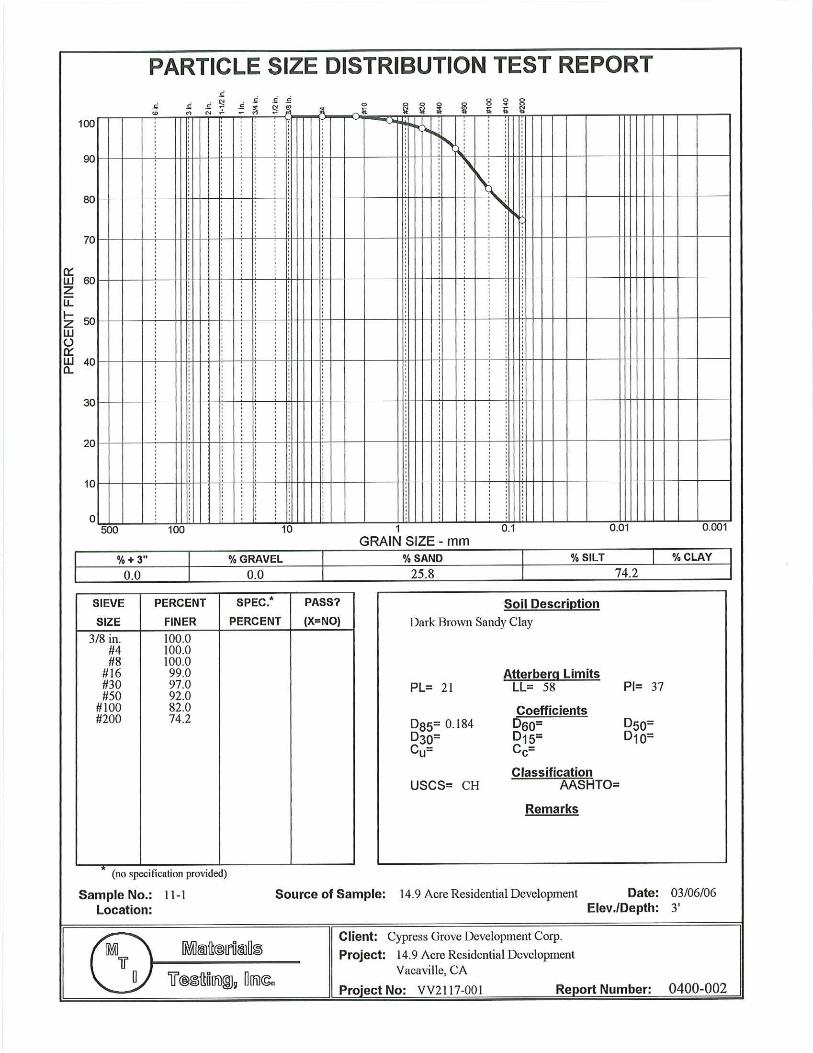

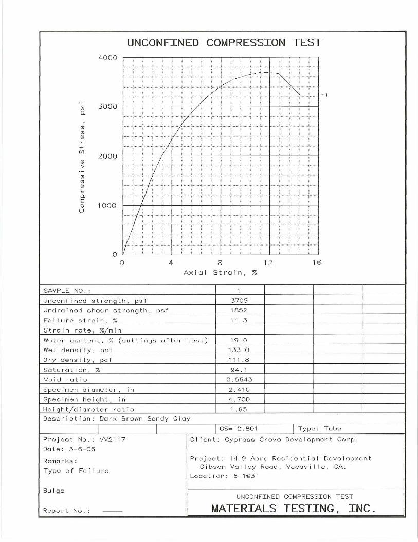


4/9/2019 U.S. Seismic Design Maps
https://seismicmaps.org 1/2
Gibson Canyon Rd., VacavilleLatitude, Longitude: 38.3677, -121.9903
Date 4/9/2019, 3:00:14 PM
Design Code Reference Document ASCE7-10
Risk Category II
Site Class D - Stiff Soil
Type Value DescriptionSS 1.85 MCER ground motion. (for 0.2 second period)
S1 0.628 MCER ground motion. (for 1.0s period)
SMS 1.85 Site-modified spectral acceleration value
SM1 0.941 Site-modified spectral acceleration value
SDS 1.233 Numeric seismic design value at 0.2 second SA
SD1 0.628 Numeric seismic design value at 1.0 second SA
Type Value DescriptionSDC D Seismic design category
Fa 1 Site amplification factor at 0.2 second
Fv 1.5 Site amplification factor at 1.0 second
PGA 0.686 MCEG peak ground acceleration
FPGA 1 Site amplification factor at PGA
PGAM 0.686 Site modified peak ground acceleration
TL 8 Long-period transition period in seconds
SsRT 1.85 Probabilistic risk-targeted ground motion. (0.2 second)
SsUH 1.887 Factored uniform-hazard (2% probability of exceedance in 50 years) spectral acceleration
SsD 2.279 Factored deterministic acceleration value. (0.2 second)
S1RT 0.628 Probabilistic risk-targeted ground motion. (1.0 second)
S1UH 0.627 Factored uniform-hazard (2% probability of exceedance in 50 years) spectral acceleration.
S1D 0.737 Factored deterministic acceleration value. (1.0 second)
PGAd 0.863 Factored deterministic acceleration value. (Peak Ground Acceleration)
CRS 0.98 Mapped value of the risk coefficient at short periods
CR1 1.001 Mapped value of the risk coefficient at a period of 1 s

4/9/2019 U.S. Seismic Design Maps
https://seismicmaps.org 2/2
DISCLAIMER
While the information presented on this website is believed to be correct, SEAOC /OSHPD and its sponsors and contributors assume no responsibility or liability for its accuracy. The material presented in this webapplication should not be used or relied upon for any specific application without competent examination and verification of its accuracy, suitability and applicability by engineers or other licensed professionals. SEAOC /OSHPD do not intend that the use of this information replace the sound judgment of such competent professionals, having experience and knowledge in the field of practice, nor to substitute for the standard of care required ofsuch professionals in interpreting and applying the results of the seismic data provided by this website. Users of the information from this website assume all liability arising from such use. Use of the output of this website doesnot imply approval by the governing building code bodies responsible for building code approval and interpretation for the building site described by latitude/longitude location in the search results of this webstie.
MCER Response Spectrum
Sa(g)
0.0 2.5 5.0 7.50.0
0.5
1.0
1.5
2.0
Period, T (sec)
Sa(
g)
Design Response Spectrum
Sa(g)
0.0 2.5 5.0 7.50.0
0.5
1.0
1.5
Period, T (sec)
Sa(
g)