geotechnical engineering services - snohomish … · shallow foundations and mat ... this report...
TRANSCRIPT

DGeo Cap Sante Boat Haven M, N, O-DockMaintenance Dredge ProjectAnacortes, Washington
forPort of Anacortes
June 7, 2012
Earth Science + Technology

Geotechnical Engineering Services
Snoqualmie Switch Station Snoqualmie, Washington
for Puget Sound Energy
March 25, 2013
Plaza 600 Building 600 Stewart Street, Suite 1700 Seattle, Washington 98101 206.728.2674


March 25, 2013 | Page i File No. 0186-679-10
Table of Contents
INTRODUCTION AND SCOPE ..................................................................................................................... 1
FIELD EXPLORATION AND LABORATORY TESTING .................................................................................. 1
Field Explorations ................................................................................................................................... 1
SITE CONDITIONS ....................................................................................................................................... 1
Sensitive Areas ....................................................................................................................................... 1 Geology ................................................................................................................................................... 2 Surface Conditions ................................................................................................................................. 2 Subsurface Conditions .......................................................................................................................... 2
CONCLUSIONS AND RECOMMENDATIONS .............................................................................................. 2
Seismic Design ....................................................................................................................................... 2 IBC Design Parameters ................................................................................................................... 2
Shallow Foundations and Mat Foundations ......................................................................................... 3 Allowable Soil Bearing Pressure ..................................................................................................... 3 Embedment ..................................................................................................................................... 3 Settlement ....................................................................................................................................... 3 Lateral Resistance .......................................................................................................................... 4 Construction Considerations .......................................................................................................... 4
Retaining Walls ...................................................................................................................................... 4 General ............................................................................................................................................ 4 Design Parameters.......................................................................................................................... 5 Wall Drainage .................................................................................................................................. 5 Global Stability Analyses ................................................................................................................. 5
Storm Drain Pipe .................................................................................................................................... 5 Slope Stability .................................................................................................................................. 5 Steep Slope Construction Recommendations .............................................................................. 6
Earthwork ............................................................................................................................................... 7 Excavation Considerations ............................................................................................................. 7 Clearing and Grubbing .................................................................................................................... 7 Subgrade Preparation ..................................................................................................................... 7 Erosion and Sedimentation Control ............................................................................................... 7 Structural Fill ................................................................................................................................... 8 Weather Considerations ................................................................................................................. 9 Temporary Slopes ......................................................................................................................... 10 Permanent Slopes ......................................................................................................................... 10
LIMITATIONS ........................................................................................................................................... 11
REFERENCES .......................................................................................................................................... 11

Page ii | March 25, 2013 | GeoEngineers, Inc. File No. 0186-679-10
Table of Contents (continued)
LIST OF FIGURES
Figure 1. Vicinity Map Figure 2. Site Plan Figure 3. Global Stability Analysis – Static and Seismic Conditions
APPENDICES
Appendix A. Field Explorations Figure A-1. Key to Exploration Logs Figures A-2 through A-8. Logs of Borings
Appendix B. Report Limitations and Guidelines for Use

SNOQUALMIE SWITCH STATION Snoqualmie, Washington
March 25, 2013 | Page 1 File No. 0186-679-10
INTRODUCTION AND SCOPE
This report summarizes the results of our geotechnical engineering services for the proposed improvements to the existing Puget Sound Energy (PSE) Snoqualmie Switch Station. The site is located east of Salish Lodge off Railroad Avenue in Snoqualmie, Washington. The site is shown in relation to the surrounding area on the Vicinity Map, Figure 1, and the Site Plan, Figure 2. We previously issued a draft of this report dated March 15, 2015; this report supersedes our previous report.
We understand that the proposed improvements include bringing in underground feeder lines from Snohomish County Public Utility District run-of-the-river hydroelectric projects at Hancock Creek and Calligan Creek. These underground feeders will enter from the north and tie into the existing PSE switch station using a new regulator, transformer, and breaker switch, which will be located at the east end of the existing station. The improvements will require expansion onto the steep slope to the east, including a new retaining wall that will be approximately 2 to 9 feet high. Due to space limitations, the retaining wall will likely be a reinforced concrete wall. The proposed improvements will include modifications to the existing storm drainage system, including a new catch basin behind the retaining wall and a new drain pipe extending south down the steep slope and connecting to an existing catch basin that discharges into the Snoqualmie River. The approximate locations of the proposed improvements are shown on the attached Site Plan, Figure 2.
Our geotechnical engineering services were completed in general accordance with our proposal dated February 12, 2013. Our scope of service includes:
■ Completing four borings and three hand-augered borings at the site;
■ Providing geotechnical conclusions and recommendations for the proposed improvements, and
■ Preparing this report.
FIELD EXPLORATION AND LABORATORY TESTING
Field Explorations
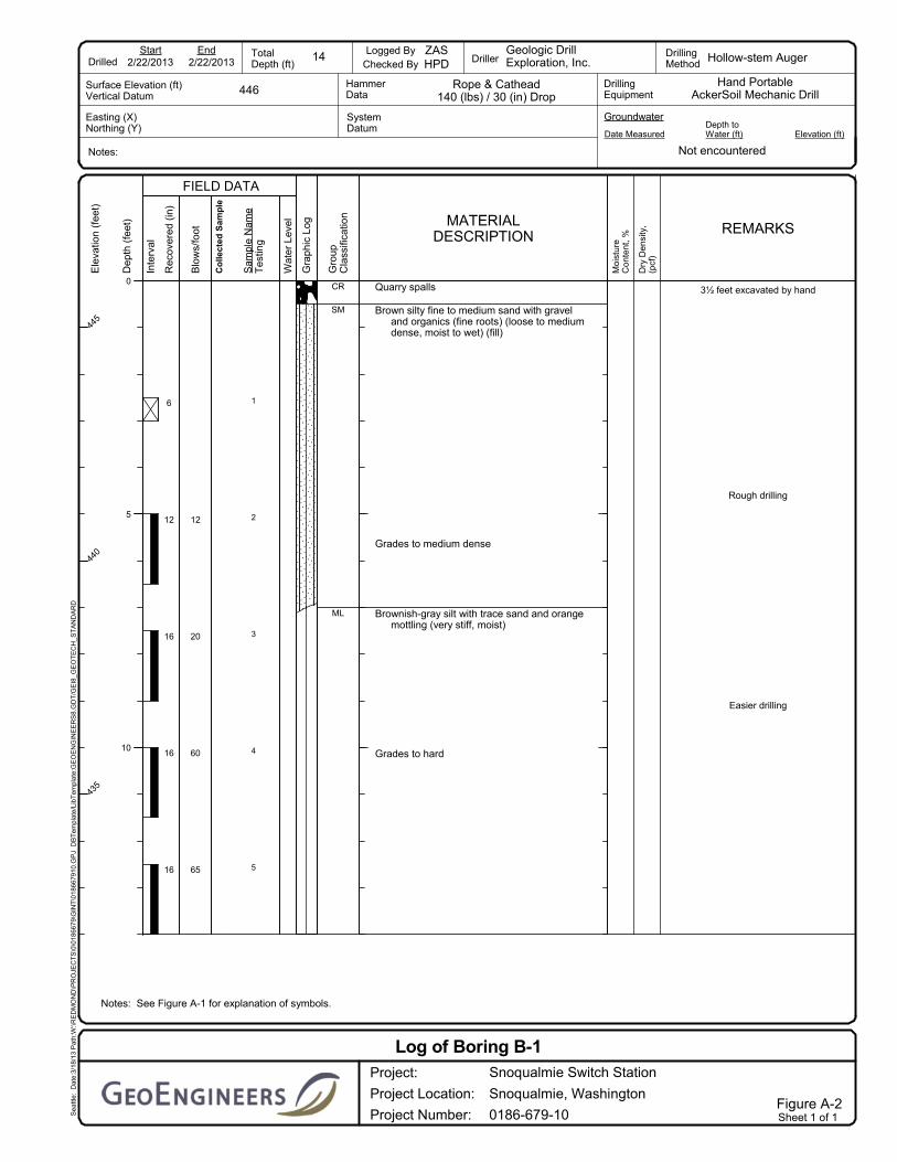
The subsurface conditions at the site were evaluated by completing four borings (B-1 through B-4) to depths ranging from 11½ to 14 feet below existing site grades, and three hand-augered borings (HA-1 through HA-3). The approximate locations of the explorations are shown on the Site Plan, Figure 2. A detailed description of the field exploration program is presented in Appendix A.
SITE CONDITIONS
Sensitive Areas
We reviewed the available sensitive areas maps published online by King County. The maps include identification of areas with significant landslide, seismic, erosion, and coal mine hazards. No geologic sensitive areas are mapped in the vicinity of the proposed switch station improvements; however, based on the slope inclination, the steep slope would be characterized as an erosion and steep slope hazard area.

SNOQUALMIE SWITCH STATION Snoqualmie, Washington
Page 2 | March 25, 2013 | GeoEngineers, Inc. File No. 0186-679-10
Geology
Geologic information for the project area (Dragovich, Joe D., Littke, Heather A., Anderson, Megan L., et al., 2009) indicates that surficial soils mapped at the site consist of glaciolacustrine deposits and alluvium underlain by bedrock. Glaciolacustrine deposits generally consist of silt, clayey or sandy silt, and silty sand, typically with scattered dropstones and occasional layers and lenses of sand and/or gravel. Alluvium generally consists of well sorted/stratified sand and silt with lesser gravelly sand, sandy pebble gravel, peat, and organic sediments. The glaciolacustrine deposits or alluvium is underlain by bedrock (Volcanic rocks of Snoqualmie Falls - Miocene).
Surface Conditions
The site is bounded by Railroad Avenue to the north, Salish Lodge to the west, a paved surface parking lot to the east, and a construction access road to the south. The ground surface slopes down from the north where it is about Elevation 446 feet, to about Elevation 416 feet at the south margin of the site. The area of the proposed improvements is currently undeveloped and forested with deciduous and coniferous trees and brush.
Subsurface Conditions
Based on the explorations performed at the site, the subsurface conditions generally consist of topsoil and fill overlying glaciolacustrine deposits. We observed approximately 4 to 6 inches of topsoil in most of the explorations. The topsoil generally consists of forest duff and organic soil. Below the topsoil, we observed fill consisting of loose to medium dense silty sand/sandy silt with organics (fine roots, charcoal) and varying gravel content to a depth of approximately 3 to 7 feet. Below the fill, we observed glaciolacustrine deposits consisting of very stiff to hard silt with variable amounts of gravel. The glaciolacustrine deposits extended to the depths explored. Bedrock was not encountered in the explorations.
No groundwater was observed during drilling. These observations may or may not be representative of the long-term groundwater conditions at the site.
CONCLUSIONS AND RECOMMENDATIONS
Seismic Design
IBC Design Parameters
We recommend the 2012 International Building Code (IBC) parameters for Site Class, short period spectral response acceleration (SS), one-second period spectral response acceleration (S1) and Seismic Coefficients FA and FV presented in the following table.
SNOQUALMIE SWITCH STATION Snoqualmie, Washington
March 25, 2013 | Page 3 File No. 0186-679-10
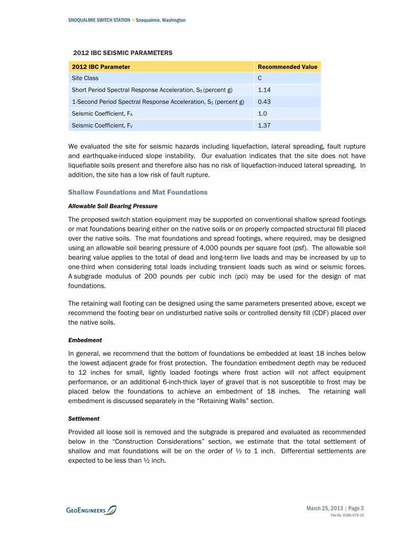
2012 IBC SEISMIC PARAMETERS
2012 IBC Parameter Recommended Value
Site Class C
Short Period Spectral Response Acceleration, SS (percent g) 1.14
1-Second Period Spectral Response Acceleration, S1 (percent g) 0.43
Seismic Coefficient, FA 1.0
Seismic Coefficient, FV 1.37
We evaluated the site for seismic hazards including liquefaction, lateral spreading, fault rupture and earthquake-induced slope instability. Our evaluation indicates that the site does not have liquefiable soils present and therefore also has no risk of liquefaction-induced lateral spreading. In addition, the site has a low risk of fault rupture.
Shallow Foundations and Mat Foundations
Allowable Soil Bearing Pressure
The proposed switch station equipment may be supported on conventional shallow spread footings or mat foundations bearing either on the native soils or on properly compacted structural fill placed over the native soils. The mat foundations and spread footings, where required, may be designed using an allowable soil bearing pressure of 4,000 pounds per square foot (psf). The allowable soil bearing value applies to the total of dead and long-term live loads and may be increased by up to one-third when considering total loads including transient loads such as wind or seismic forces. A subgrade modulus of 200 pounds per cubic inch (pci) may be used for the design of mat foundations.
The retaining wall footing can be designed using the same parameters presented above, except we recommend the footing bear on undisturbed native soils or controlled density fill (CDF) placed over the native soils.
Embedment
In general, we recommend that the bottom of foundations be embedded at least 18 inches below the lowest adjacent grade for frost protection. The foundation embedment depth may be reduced to 12 inches for small, lightly loaded footings where frost action will not affect equipment performance, or an additional 6-inch-thick layer of gravel that is not susceptible to frost may be placed below the foundations to achieve an embedment of 18 inches. The retaining wall embedment is discussed separately in the “Retaining Walls” section.
Settlement
Provided all loose soil is removed and the subgrade is prepared and evaluated as recommended below in the “Construction Considerations” section, we estimate that the total settlement of shallow and mat foundations will be on the order of ½ to 1 inch. Differential settlements are expected to be less than ½ inch.

SNOQUALMIE SWITCH STATION Snoqualmie, Washington
Page 4 | March 25, 2013 | GeoEngineers, Inc. File No. 0186-679-10
Lateral Resistance
Lateral foundation loads can be resisted by passive resistance on the sides of foundations and by friction on the base of the foundations. For foundations supported on native soils or on structural fill placed and compacted in accordance with our recommendations, the allowable frictional resistance can be computed using a coefficient of friction of 0.35 applied to vertical dead-load forces.
The allowable passive resistance can be computed using an equivalent fluid density of 300 pounds per cubic foot (pcf) (triangular distribution) if these elements are poured directly against compacted native soils or surrounded by structural fill. The structural fill should extend out from the face of the foundation element for a distance at least equal to three times the height of the element and be compacted to at least 95 percent of the maximum dry density (MDD) estimated in general accordance with American Society for Testing and Materials (ASTM) D 1557. For the retaining wall footing, due to the descending slope in front of the wall, passive resistance should be neglected.
The above coefficient of friction and passive equivalent fluid density values incorporate a factor of safety of about 1.5.
Construction Considerations
If soft soil areas are present at the foundation bearing surface elevation, the soft soils in these areas must be removed and replaced with structural fill. In such instances, the zone of structural fill must extend laterally beyond the footing edges for a horizontal distance that is at least equal to the depth of overexcavation.
For the retaining wall footing, soft soil areas below the foundation subgrade elevation must be removed and replaced with CDF. The overexcavated areas must be neat-cut to limit the extent of the excavation and limit disturbance of the soils at the face of the retaining wall.
We recommend that a representative from our firm observe the condition of all footing excavations to evaluate whether the work is completed in accordance with our recommendations and whether the subsurface conditions are as anticipated.
Retaining Walls
General
The proposed improvements will require expansion onto the steep slope to the east, and the grade transition will be accomplished by using a reinforced concrete retaining wall up to 9 feet in height. Based on our explorations, we anticipate overexcavation will be required in some areas below the retaining wall footing. Loose soils must be overexcavated and backfilled with CDF, as discussed in the previous section. Retaining walls must be backfilled with a 12-inch wide zone of drainage aggregate, with weep pipes extending to the face of the wall.
The retaining wall must have a minimum of 24 inches of embedment at the face of the wall for wall heights up to 4 feet and a minimum of 36 inches of embedment at the face of the wall for wall heights greater than 4 feet.

SNOQUALMIE SWITCH STATION Snoqualmie, Washington
March 25, 2013 | Page 5 File No. 0186-679-10
Design Parameters
We recommend the retaining wall be designed using the parameters presented in the table below. The retaining wall foundations may be designed using the recommendations previously presented in the “Shallow Foundations and Mat Foundations” section. The parameters listed below assume drainage is provided as described in the “Wall Drainage” section below.
Soil Parameters Retained Soils
Unit Weight (pcf) 125
Friction Angle (degrees) 35
Seismic Coefficient, Kh 0.15
Active Earth Pressure (pcf) – triangular distribution 31H
Seismic Pressure (psf) – uniform distribution 6H
Wall Drainage
We recommend drainage for the retaining wall be provided by placing a 12-inch-wide zone of free-draining soil behind the wall (base course or yard course meet this requirement) and installing weepholes. Permanent drainage systems must intercept surface water runoff at the top and/or bottom of cut and fill slopes to prevent the surface water from flowing in an uncontrolled manner across the wall.
Global Stability Analyses
We performed slope stability analyses to evaluate the global static and seismic (pseudostatic) stability of the proposed retaining wall. For our analyses, we used the slope stability program Slope/W 2012. Soil strength parameters for the slope stability analysis were selected by reviewing the exploration logs and from our professional judgment based on the geologic origin of the soil units. A ground acceleration of 0.15g (where g is the gravitational constant) was used for seismic (pseudostatic) analysis. This ground acceleration corresponds to 50 percent of the effective IBC design ground acceleration, which is assumed equal to the design spectral response acceleration (SDS) divided by 2.5, per Section 1803.5.12 of the IBC, where SDS is determined in accordance with Section 1613.5.4 of the IBC.
Figure 3 presents the modeled soil strength parameters and slope geometry, along with the static and seismic factors of safety and resulting critical failure surface. The global factor of safety for the slopes is at least 1.5 for static conditions and at least 1.1 for seismic conditions. Based on our slope stability analyses and geotechnical evaluation, it is our opinion that the proposed retaining wall has adequate factors of safety for global stability.
Storm Drain Pipe
Slope Stability
Based on our field observations, subsurface explorations, and experience, it is our opinion that the steep slope is susceptible to surficial soil movement. It is our opinion that the upper weathered soil layer on the slope may move slowly downslope via raveling and soil creep. Instability of this nature is confined to the upper weathered or disturbed zone of soil, which typically has lower

SNOQUALMIE SWITCH STATION Snoqualmie, Washington
Page 6 | March 25, 2013 | GeoEngineers, Inc. File No. 0186-679-10
strength than the underlying unweathered soil. This process is more significant on steeper slopes than on flatter slopes. Significant weathering typically occurs in the upper 2 to 3 feet and is the result of oxidation, root penetration, wet/dry and freeze/thaw cycles, and gravity. Erosion of the soils on the steep slope can be managed and effectively reduced through proper erosion control practices and surface restoration methods that are described in the “Earthwork” section of this report.
We recommend that the storm drain pipe be installed aboveground to limit potential impacts from slope movement. Recommendations for construction of the storm drain pipe in the steep slope area are presented below.
Steep Slope Construction Recommendations
The aboveground portion of the pipe should extend from an anchor point behind the retaining wall onto the face of the slope. The pipe should be butt-fuse welded into a continuous section of pipe, without joints.
Because the soils surrounding the pipe can experience movement, we recommend that the pipe be straight and oriented perpendicular to the contours on the face of the slope. This will reduce the loads that the soil movement could impose on the pipe, as compared with a pipe running cross-slope.
In addition, the pipe will likely experience some loss of support from surficial soil movement. Therefore, we recommend that the pipe be anchored securely at the top of the slope. We recommend against mid-slope anchorage of the pipe because any soil movement near the mid-slope anchors could cause distress to the pipe at the anchorage points. In our opinion, high density polyethylene (HDPE) pipe is appropriate for this project because the flexibility of the pipe will enable the pipe to withstand bending stresses if there is some loss of support.
The HDPE pipe should be anchored at the top of the slope with a structure designed to restrain the full weight of the pipe, plus the full weight and hydrodynamic loads of the designed stormwater contained within the pipe. We recommend that the anchorage be achieved by means of a structure of sufficient size or a structure plus a dead-man block of concrete. A manhole can be used for this structural anchorage, provided that the manhole has sufficient face area and the structural capacity to transmit the loads from the pipe into the ground. The pipe anchorage should be positioned behind the retaining wall. The anchor should be fully embedded in undisturbed dense native soil or structural fill. It may be possible to design the retaining wall as the anchorage, provided the retaining wall is properly designed for the increased lateral loads.
The capacity of the pipe anchorage can be evaluated using the parameters presented in the “Shallow Foundations and Mat Foundations” section. Lateral loads can be resisted by a combination of friction between the base of the anchor and the supporting soil, and by the passive lateral resistance of the soil at the face of the anchor.

SNOQUALMIE SWITCH STATION Snoqualmie, Washington
March 25, 2013 | Page 7 File No. 0186-679-10
Earthwork
Excavation Considerations
Topsoil, fill, and glaciolacustrine deposits were observed in the explorations. We anticipate that these soils can be excavated with conventional excavation equipment, such as trackhoes or dozers. Cobbles and boulders were encountered in the soils at the site, and the contractor should be prepared to remove them where necessary. Bedrock is anticipated to be present below the glaciolacustrine deposits, although explorations at the site did not extend to the bedrock.
Clearing and Grubbing
Trees, brush, and other vegetation, including topsoil with roots, should be stripped and removed from areas where structural fill will be placed. The stripped material should be placed in landscaping areas or transported off-site for disposal.
Subgrade Preparation
In areas where structural fill is to be placed, the upper 12 inches of existing subgrade soils must be evaluated prior to fill placement. This can be done by probing. Likewise, the bearing surface in the proposed foundation areas for structures and retaining walls must be evaluated after site grading is complete. Soft zones noted during probing must be overexcavated and replaced with compacted structural fill or CDF.
Erosion and Sedimentation Control
Potential sources or causes of erosion and sedimentation depend upon construction methods, slope length and gradient, amount of soil exposed and/or disturbed, soil type, construction sequencing and weather. The project impact on erosion-prone areas can be reduced by implementing an erosion and sedimentation control plan. The plan should be designed in accordance with applicable city and/or county standards. The plan should incorporate basic planning principles, including:
■ Scheduling grading and construction to reduce soil exposure;
■ Retaining existing vegetation whenever feasible;
■ Revegetating or mulching denuded areas;
■ Directing runoff away from denuded areas;
■ Minimizing the length and steepness of slopes with exposed soils;
■ Decreasing runoff velocities;
■ Confining sediment to the project site, and;
■ Inspecting and maintaining control measures frequently.
We recommend that graded and disturbed slopes be tracked in place with the equipment running perpendicular to the slope contours so that the track marks provide a texture to help resist erosion and channeling. Some sloughing and raveling of slopes with exposed or disturbed soil should be expected.

SNOQUALMIE SWITCH STATION Snoqualmie, Washington
Page 8 | March 25, 2013 | GeoEngineers, Inc. File No. 0186-679-10
Temporary erosion protection must be used and maintained in areas with exposed or disturbed soils to help reduce the potential for erosion and reduce transport of sediment to adjacent areas. Temporary erosion protection must include the construction of a silt fence around the perimeter of the work area prior to the commencement of grading activities. Permanent erosion protection must be provided by reestablishing vegetation using hydroseeding and/or landscape planting.
Until the permanent erosion protection is established and the site is stabilized, site monitoring must be performed by qualified personnel to evaluate the effectiveness of the erosion control measures and repair and/or modify them as appropriate. Provisions for modifications to the erosion control system based on monitoring observations must be included in the erosion and sedimentation control plan.
Structural Fill
MATERIALS
Materials used to raise site grades, placed to support structures or pavements, or used for utility trench backfill are classified as structural fill for the purpose of this report. Structural fill material quality varies depending upon its use as described below:
■ On-site soils must not be used as structural fill to support switch station equipment. On-site soils may be considered for use as structural fill for other purposes during dry weather. On-site soils may also be used during wet weather provided that they can be moisture-conditioned to meet compaction specifications. If on-site soils cannot be moisture-conditioned, imported gravel borrow must conform to Puget Sound Energy Base Course Aggregate Specification 1275.1310 as described in the following table:
US Standard Sieve Size Percent Passing (by weight)
3 inches 100
¾ inch 70 - 90
⅜ inch 60 - 80
¼ inch 50 - 70
U.S. No. 40 < 30
U.S. No. 200 5 maximum
■ Structural fill placed as “yard course crushed aggregate” surfacing material must be angular
crushed rock conforming to Puget Sound Energy Specification 1275.1330 as described in the following table:
US Standard Sieve Size Percent Passing (by weight)
1½ inches 100
1 inch 60 to 100
¾ or ⅝ inch 0 to 35
⅜ inch 0 to 5

SNOQUALMIE SWITCH STATION Snoqualmie, Washington
March 25, 2013 | Page 9 File No. 0186-679-10
FILL PLACEMENT AND COMPACTION CRITERIA
Structural fill must be mechanically compacted to a firm, non-yielding condition. In general, structural fill must be placed in loose lifts not exceeding 8 to 10 inches in thickness. Each lift must be conditioned to the proper moisture content and compacted to the specified density before placing subsequent lifts. Structural fill must be compacted to the following criteria:
■ Structural fill placed below foundations and roadways or to establish yard grades must be compacted to at least 95 percent of the MDD estimated in general accordance with ASTM D 1557. Structural fill placed to form finished slopes must also be compacted to at least 95 percent of the MDD.
■ Structural fill (including utility trench backfill) placed outside of areas where foundations, roadways, parking and yard areas are to be located must be compacted to at least 90 percent of the MDD estimated in general accordance with ASTM D 1557.
We recommend that a representative from our firm be present during proof-rolling and/or probing of the exposed subgrade soils in structure areas prior to the placement of structural fill and also during the placement of structural fill. Our representative will evaluate the adequacy of the subgrade soils and identify areas needing further work, perform in-place moisture-density tests in the fill to evaluate whether the work is being done in accordance with the compaction specifications, and advise on any modifications to procedures that may be appropriate for the prevailing conditions.
Weather Considerations
The native soils contain a sufficient percentage of fines (silt) and are moisture-sensitive. When the moisture content of these soils is appreciably above the optimum moisture content, these soils become muddy and unstable, operation of equipment on these soils will be difficult and it will be difficult to meet the required compaction criteria. Additionally, disturbance of these near-surface soils should be expected if earthwork is completed during periods of wet weather.
The wet weather season in the Puget Sound region generally begins in October and continues through May; however, periods of wet weather can occur during any month of the year. The optimum earthwork period for these types of soils is typically June through September. If wet weather earthwork is unavoidable, we recommend that:
■ Stockpiles of on-site soils that will be used as structural fill during wet weather be covered with plastic sheeting to protect them from rain.
■ If on-site soils cannot be moisture-conditioned to meet compaction requirements during wet weather, imported gravel borrow must be used as discussed previously in the “Structural Fill” section of this report.
■ The ground surface in and around the work area be sloped so that surface water is directed away from the work area. The ground surface must be graded such that areas of ponded water do not develop. The contractor must take measures to prevent surface water from collecting in excavations and trenches. Measures must be implemented to remove surface water from the work area.

SNOQUALMIE SWITCH STATION Snoqualmie, Washington
Page 10 | March 25, 2013 | GeoEngineers, Inc. File No. 0186-679-10
Temporary Slopes
The soils encountered at the site are classified as Type C soil in accordance with the provisions of Title 296-155 of the Washington Administrative Code (WAC), Part N, “Excavation, Trenching, and Shoring”. We recommend that temporary slopes in excess of 4 feet in height be inclined no steeper than 1H:1V. Flatter slopes may be necessary if localized sloughing occurs. For open cuts at the site, we recommend that:
■ No traffic, construction equipment, stockpiles or building supplies be allowed at the top of cut slopes within a distance of at least 5 feet from the top of the cut.
■ Exposed soil along the slope be protected from surface erosion using waterproof tarps or plastic sheeting.
■ Construction activities be scheduled so that the length of time that the temporary cut is left open is kept as short as possible.
■ Erosion control measures be implemented as appropriate such that runoff from the site is reduced to the extent practicable.
■ Surface water be diverted away from the excavation.
■ The general condition and stability of the slopes be visually assessed periodically by a geotechnical engineer.
Because the contractor has control of the construction operations, the contractor must be made responsible for the stability of all temporary slopes, as well as the safety of the excavations. All shoring and temporary slopes must conform to applicable local, state and federal safety regulations.
Permanent Slopes
We recommend that permanent cut and fill slopes be constructed no steeper than 2H:1V. To achieve uniform compaction, we recommend that fill slopes be overbuilt slightly and subsequently cut back to expose properly compacted fill. Fill placed on existing slopes that are steeper than 5H:1V must be properly keyed into the native soil slope surface. This can be done by constructing the fill in a series of 6- to 8-foot-wide horizontal benches cut into the slope. Bench surfaces must be thoroughly compacted prior to placing the fill soils.
To reduce erosion, newly constructed slopes must be planted or hydroseeded shortly after completion of grading. Until the vegetation is established, some sloughing and raveling of the slopes should be expected. This may require localized repairs and reseeding. Temporary covering, such as clear heavy plastic sheeting, jute fabric, loose straw or excelsior matting must be used to protect the slopes during periods of rainfall.

SNOQUALMIE SWITCH STATION Snoqualmie, Washington
March 25, 2013 | Page 11 File No. 0186-679-10
LIMITATIONS
We have prepared this report for the exclusive use of Puget Sound Energy and their authorized agents for the proposed Snoqualmie Switch Station Improvements in Snoqualmie, Washington.
Within the limitations of scope, schedule and budget, our services have been executed in accordance with generally accepted practices in the field of geotechnical engineering in this area at the time this report was prepared. No warranty or other conditions, express or implied, should be understood.
Any electronic form, facsimile or hard copy of the original document (email, text, table, and/or figure), if provided, and any attachments are only a copy of the original document. The original document is stored by GeoEngineers, Inc. and will serve as the official document of record.
Please refer to Appendix B, Report Limitations and Guidelines for Use, for additional information pertaining to use of this report.
REFERENCES
International Code Council, “International Building Code.” 2012.
Dragovich, Joe D., Littke, Heather A., Anderson, Megan L., et al., 2009, Geologic map of the Snoqualmie 7.5-minute quadrangle, King County, Washington, Washington Division of Geology and Earth Resources Geologic Map GM-75.
King Country GIS database. URL: http://www.metrokc.gov/gis/mapportal/iMAP_main.htm.
United States Geological Survey, U.S. Seismic Design Maps, 2008 data, accessed on 3/12/13 at: http://geohazards.usgs.gov/designmaps/us/application.php.

Earth Science + Technology
Type Name of Services HereName of Project Here
forType Client Name Here
Type Date of Report Here

Three Forks ParkThree Forks ParkRiver View ParkRiver View Park
Borst LakeBorst Lake
Snoqualmie RiverSnoqualmie River
Meadowbrook SloughMeadowbrook Slough
Tokul CreekTokul Creek
SSnnooqquuaal lmmiiee RR iivveerr
MM uu dd CC rr ee ee kk
CC oo aa ll CC rr ee ee kk
KKiimmbbaallll CCrreeeekk
SE 80Th St
SE Tokul Rd
Mill Pond Rd
SE Park St
SE 47Th St
Preston Snoqualmie Trl
396Th Dr SE
Falls Ave SE
SE 60Th St
396T
h Ave
SE
378T
h Ave
SE Silva
St
SE David Powell Rd
SE 53Rd St
384T
h Ave
SE
SE 49Th St
SE 86Th St
Fish Hatchery Rd
364T
h Ave
SE
372N
d Pl S
E
Stearns Rd
SE Cedar St
2Nd Ave NW
SE 70Th Dr
Railroad Pl SE
SE 47Th Pl
Alpha St
402Nd Ave SE
King St
SE 77Th St
SE 85Th St
372Nd Ave SE371St Ct SE
SE 82Nd St
SE 56Th St
376Th Ave SE
382N
d Ave
SE
SE Gravenstein Ct
365Th
Ave SE
358T
h Ave
SE
4Th St
SE 88Th St
Railroad Pl SE
SE 60Th St
UV202
µ
Vicinity Map
Figure 1
Snoqualmie Switch StationSnoqualmie, Washington
King
Snohomish
Kittitas
Kitsap
Pierce
SeattleBellevue
§̈¦90
§̈¦5 §̈¦405
UV167
2,000 2,0000
Feet
Data Sources: ESRI Data & Maps, Street Maps 2005
Notes:1. The locations of all features shown are approximate.2. This drawing is for information purposes. It is intended to assist in showing features discussed in an attached document. GeoEngineers, Inc. cannot guarantee the accuracy and content of electronic files. The master file is stored by GeoEngineers, Inc. and will serve as the official record of this communication.3. It is unlawful to copy or reproduce all or any part thereof, whether for personal use or resale, without permission.
Transverse Mercator, Zone 10 N North, North American Datum 1983North arrow oriented to grid northOf
fice:
Redm
ond
Path:
\\red
\proje
cts\0\
0186
679\G
IS\01
8667
910_
F1_V
icinity
Map.m
xdMa
p Rev
ised:
3/14
/2013
E
L
Site

HA-2
HA-1
HA-3
B-1 B-2
B-3
B-4
FEET020 20
W E
N
S
Boring by GeoEngineersHand Auger by GeoEngineers
Notes1. The locations of all features shown are approximate.2. This drawing is for information purposes. It is intended to assist in
showing features discussed in an attached document.GeoEngineers, Inc. cannot guarantee the accuracy and contentof electronic files. The master file is stored by GeoEngineers, Inc.and will serve as the official record of this communication.
Reference: CAD file "SK-056401.dwg" provided by PSE on 3-4-13.
B-1
HA-1
Legend
Figure 2
Snoqualmie Switch StationSnoqualmie, Washington
Site Plan

Not to Scale
SharePoint Working\Figure 3 Slope Stability Analyses.ppt HPD:tb2 03/08/13
Global Stability AnalysisStatic and Seismic Conditions
Snoqualmie Switch StationSnoqualmie, Washington
Figure 3

Earth Science + Technology
Type Name of Services HereName of Project Here
forType Client Name Here
Type Date of Report Here

APPENDIX A Field Explorations

SNOQUALMIE SWITCH STATION Snoqualmie, Washington
March 25, 2013 | Page A-1 File No. 0186-679-10
APPENDIX A FIELD EXPLORATIONS
Field Explorations
Subsurface conditions were explored at the site by completing four borings (B-1 through B-4), and three hand-augered borings (HA-1 through HA-3). The borings were completed by Geologic Drill Exploration Inc of Bellevue, Washington, on February 22, 2013. The locations of the explorations were estimated in the field by measuring distances from site features through taping and pacing. The approximate locations of the explorations are shown on the Site Plan, Figure 2. Exploration elevations were estimated based on a site plan (SK-056401.dwg) provided by Puget Sound Energy on March 4, 2013.
Borings
The borings were drilled using a hand-portable hollow-stem auger drill rig. The borings were continuously observed by a geotechnical engineer from our firm who examined and classified the soils encountered, collected soil samples, observed groundwater conditions and prepared a detailed log of each boring. The soils encountered in the borings were sampled with a 2-inch outside diameter split-barrel standard penetration test (SPT) sampler or with a 3-inch diameter Shelby tube sampler. The SPT samples were obtained by driving the sampler 18 inches into the soil with a 140-pound hammer free-falling 30 inches. The number of blows required for each 6 inches of penetration was recorded. The blow count ("N-value") of the soil was calculated as the number of blows required for the final 12 inches of penetration. This resistance, or N-value, provides a measure of the relative density of granular soils and the relative consistency of cohesive soils. Where very dense soil conditions precluded driving the full 18 inches, the penetration resistance for the partial penetration was entered on the log. The blow counts are shown on the boring logs at the respective sample depths. The Shelby tube sampler was pushed into the soft peat to collect relatively undisturbed samples for laboratory consolidation testing.
Soils encountered in the borings were visually classified in general accordance with the classification system described in Figure A-1. A key to the exploration log symbols is also presented in Figure A-1. The logs of the borings are presented in Figures A-2 through A-4. The logs reflect our interpretation of the field conditions and the results of laboratory testing and evaluation of samples. They also indicate the depths at which the soil types or their characteristics change, although the change might actually be gradual.
The borings were backfilled in accordance with Department of Ecology standards. No groundwater was observed during drilling. These observations may or may not be representative of the long-term groundwater conditions at the site.
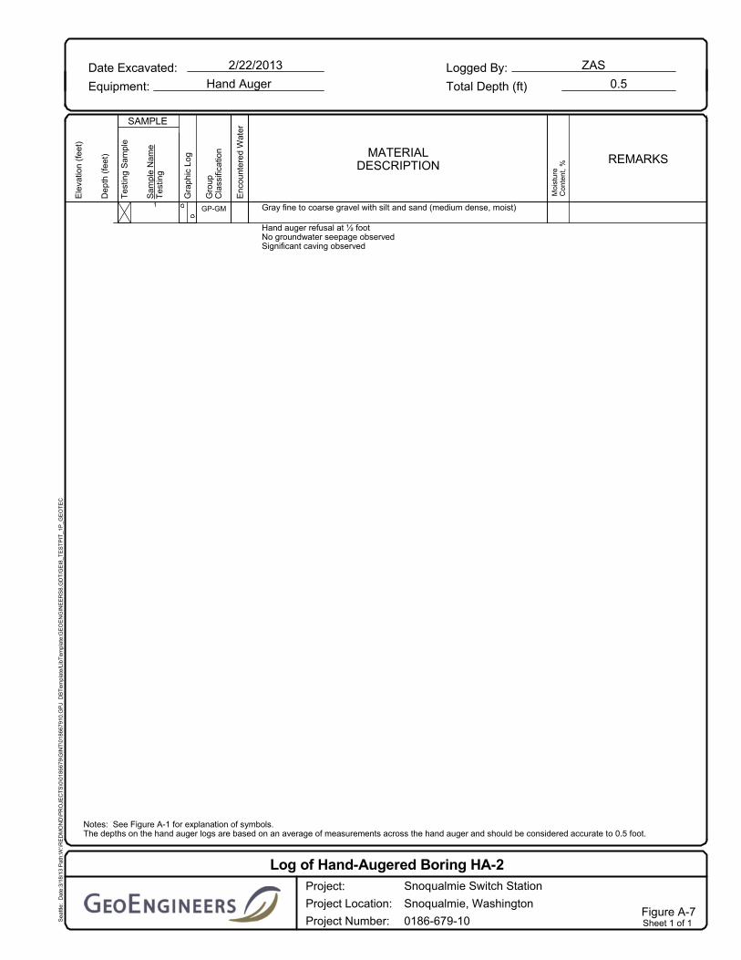
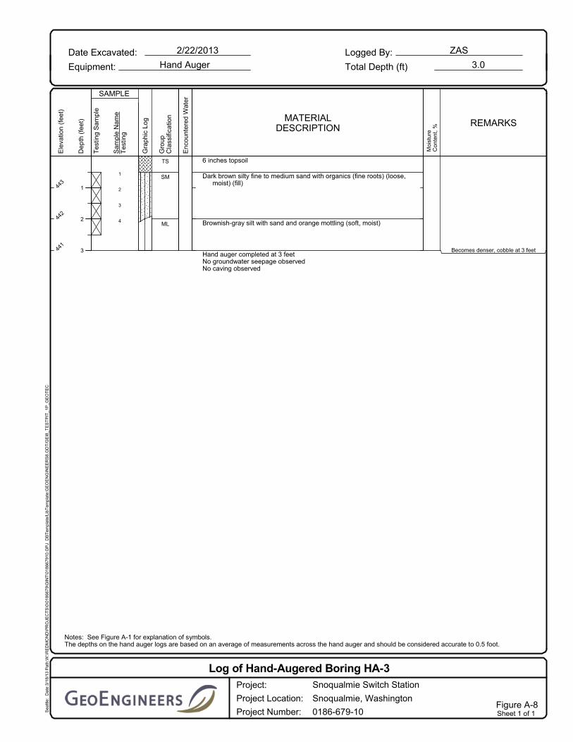
Hand-Augered Borings
Hand-augered borings were completed using hand tools. The hand-augered borings were completed by GeoEngineers, Inc on February 22, 2013 and were continuously monitored by a representative from our firm who examined and classified the soils encountered, obtained representative soil samples, observed groundwater conditions and prepared a detailed log of each exploration.

SNOQUALMIE SWITCH STATION Snoqualmie, Washington
Page A-2 | March 25, 2013 | GeoEngineers, Inc. File No. 0186-679-10
Soils encountered in the hand-augered borings were visually classified in general accordance with the classification system described in Figure A-1. A key to the hand-augered boring log symbols is also presented in Figure A-1. The logs of the borings are presented in Figures A-5 through A-7. The hand-augered boring logs are based on our interpretation of the field data, and indicate the various types of soils encountered.
No groundwater was observed during excavation of the hand-augered borings. These observations may or may not be representative of the long-term groundwater conditions at the site.

Sheen Classification
NOTE: The reader must refer to the discussion in the report text and the logs of explorations for a proper understanding of subsurfaceconditions. Descriptions on the logs apply only at the specific exploration locations and at the time the explorations were made; they arenot warranted to be representative of subsurface conditions at other locations or times.
CC
Asphalt Concrete
NSSSMSHSNT
Shelby tube
ADDITIONAL MATERIAL SYMBOLS
%FALCACPCSDSHAMCMDOCPMPIPPPPMSATXUCVS
Graphic Log Contact
Distinct contact between soil strata orgeologic units
Approximate location of soil stratachange within a geologic soil unit
Approximate location of soil stratachange within a geologic soil unit
Measured groundwater level inexploration, well, or piezometer
Measured free product in well orpiezometer
GRAPH
Topsoil/Forest Duff/Sod
Direct-Push
Crushed Rock/Quarry Spalls
Blowcount is recorded for driven samplers as the numberof blows required to advance sampler 12 inches (ordistance noted). See exploration log for hammer weightand drop.
A "P" indicates sampler pushed using the weight of thedrill rig.
FIGURE A-1
2.4-inch I.D. split barrel
SYMBOLS TYPICAL
KEY TO EXPLORATION LOGS
CR
Bulk or grab
Piston
Standard Penetration Test (SPT)
DESCRIPTIONSLETTER
Distinct contact between soil strata orgeologic units
TSGC
PT
OH
CH
MH
OL
GM
GP
GW
DESCRIPTIONSTYPICAL
LETTER
(APPRECIABLE AMOUNTOF FINES)
MAJOR DIVISIONS
POORLY-GRADED SANDS,GRAVELLY SAND
PEAT, HUMUS, SWAMP SOILSWITH HIGH ORGANICCONTENTS
CLEAN SANDS
GRAVELS WITHFINES
CLEANGRAVELS
HIGHLY ORGANIC SOILS
SILTSAND
CLAYS
SILTSAND
CLAYS
SANDAND
SANDYSOILS
GRAVELAND
GRAVELLYSOILS
(LITTLE OR NO FINES)
FINEGRAINED
SOILS
COARSEGRAINED
SOILS
SW
MORE THAN 50%OF COARSEFRACTION
RETAINED ON NO.4 SIEVE
CL
WELL-GRADED SANDS,GRAVELLY SANDS
SILTY GRAVELS, GRAVEL - SAND- SILT MIXTURES
LIQUID LIMITGREATER THAN 50
SILTY SANDS, SAND - SILTMIXTURES
(APPRECIABLE AMOUNTOF FINES)
SOIL CLASSIFICATION CHART
LIQUID LIMITLESS THAN 50
SANDS WITHFINES
SP(LITTLE OR NO FINES)
ML
SC
SM
NOTE: Multiple symbols are used to indicate borderline or dual soil classifications
MORE THAN 50%OF COARSEFRACTION
PASSING NO. 4SIEVE
CLAYEY GRAVELS, GRAVEL -SAND - CLAY MIXTURES
CLAYEY SANDS, SAND - CLAYMIXTURES
INORGANIC SILTS, ROCKFLOUR, CLAYEY SILTS WITHSLIGHT PLASTICITY
ORGANIC SILTS AND ORGANICSILTY CLAYS OF LOWPLASTICITY
INORGANIC SILTS, MICACEOUSOR DIATOMACEOUS SILTYSOILS
ORGANIC CLAYS AND SILTS OFMEDIUM TO HIGH PLASTICITY
INORGANIC CLAYS OF HIGHPLASTICITY
MORE THAN 50%PASSING NO. 200
SIEVE
MORE THAN 50%RETAINED ON NO.
200 SIEVE
WELL-GRADED GRAVELS,GRAVEL - SAND MIXTURES
POORLY-GRADED GRAVELS,GRAVEL - SAND MIXTURES
INORGANIC CLAYS OF LOW TOMEDIUM PLASTICITY, GRAVELLYCLAYS, SANDY CLAYS, SILTYCLAYS, LEAN CLAYS
GRAPH
SYMBOLS
AC
Cement Concrete
Sampler Symbol Descriptions
Groundwater Contact
Material Description Contact
No Visible SheenSlight SheenModerate SheenHeavy SheenNot Tested
Laboratory / Field TestsPercent finesAtterberg limitsChemical analysisLaboratory compaction testConsolidation testDirect shearHydrometer analysisMoisture contentMoisture content and dry densityOrganic contentPermeability or hydraulic conductivityPlasticity indexPocket penetrometerParts per millionSieve analysisTriaxial compressionUnconfined compressionVane shear
1
2
3
4
5
6
12
16
16
16
12
20
60
65
Quarry spalls
Brown silty fine to medium sand with graveland organics (fine roots) (loose to mediumdense, moist to wet) (fill)
Grades to medium dense
Brownish-gray silt with trace sand and orangemottling (very stiff, moist)
Grades to hard
CR
SM
ML
3½ feet excavated by hand
Rough drilling
Easier drilling
TotalDepth (ft)
HammerData
SystemDatum
Start EndChecked ByLogged By
HPDDrilled
Notes:
ZAS
Surface Elevation (ft)Vertical Datum
Driller
GroundwaterDepth toWater (ft)Date Measured Elevation (ft)
Easting (X)Northing (Y)
Hand PortableAckerSoil Mechanic Drill
Geologic DrillExploration, Inc.
DrillingMethod
Hollow-stem Auger14
Rope & Cathead140 (lbs) / 30 (in) Drop
DrillingEquipment
2/22/20132/22/2013
Not encountered
446
Notes: See Figure A-1 for explanation of symbols.
FIELD DATA
Dep
th (
feet
)
0
5
10
Inte
rval
Ele
vatio
n (f
eet)
445
440
435
Sam
ple
Nam
eT
estin
g
Rec
over
ed (
in)
Gra
phic
Log
Co
llect
ed S
amp
le
Blo
ws/
foot
MATERIALDESCRIPTION
Gro
upC
lass
ifica
tion
Wat
er L
evel
Log of Boring B-1Snoqualmie Switch Station
Snoqualmie, Washington
0186-679-10
Project:
Project Location:
Project Number:Figure A-2Sheet 1 of 1S
eattl
e: D
ate:
3/18
/13
Pat
h:W
:\RE
DM
ON
D\P
RO
JEC
TS
\0\0
1866
79\G
INT
\018
6679
10.G
PJ
DB
Tem
plat
e/Li
bTem
plat
e:G
EO
EN
GIN
EE
RS
8.G
DT
/GE
I8_G
EO
TE
CH
_ST
AN
DA
RD
REMARKS
Moi
stur
eC
onte
nt,
%
Dry
Den
sity
,(p
cf)

1
2
3
4
10
12
16
14
25
52
50/5.5"
50/5"
Dark brown silty fine to medium sand with tracegravel and organics (fine roots) (loose tomedium dense, moist) (fill)
Brownish-gray silt with trace sand, occasionalgravel, and orange mottling (very stiff,moist)
Brownish-gray silt with trace sand and orangemottling (hard, moist)
Grades to moist to wet
SM
ML
ML
TotalDepth (ft)
HammerData
SystemDatum
Start EndChecked ByLogged By
HPDDrilled
Notes:
ZAS
Surface Elevation (ft)Vertical Datum
Driller
GroundwaterDepth toWater (ft)Date Measured Elevation (ft)
Easting (X)Northing (Y)
Hand PortableAckerSoil Mechanic Drill
Geologic DrillExploration, Inc.
DrillingMethod
Hollow-stem Auger11.5
Rope & Cathead140 (lbs) / 30 (in) Drop
DrillingEquipment
2/22/20132/22/2013
Not encountered
448
Notes: See Figure A-1 for explanation of symbols.
FIELD DATA
Dep
th (
feet
)
0
5
10
Inte
rval
Ele
vatio
n (f
eet)
445
440
Sam
ple
Nam
eT
estin
g
Rec
over
ed (
in)
Gra
phic
Log
Co
llect
ed S
amp
le
Blo
ws/
foot
MATERIALDESCRIPTION
Gro
upC
lass
ifica
tion
Wat
er L
evel
Log of Boring B-2Snoqualmie Switch Station
Snoqualmie, Washington
0186-679-10
Project:
Project Location:
Project Number:Figure A-3Sheet 1 of 1S
eattl
e: D
ate:
3/18
/13
Pat
h:W
:\RE
DM
ON
D\P
RO
JEC
TS
\0\0
1866
79\G
INT
\018
6679
10.G
PJ
DB
Tem
plat
e/Li
bTem
plat
e:G
EO
EN
GIN
EE
RS
8.G
DT
/GE
I8_G
EO
TE
CH
_ST
AN
DA
RD
REMARKS
Moi
stur
eC
onte
nt,
%
Dry
Den
sity
,(p
cf)

1
2
3
4
4
18
18
18
5
3
21
50/6"
GravelDark brown silty fine to coarse sand with gravel
and organics (fine roots) (loose, moist) (fill)
Brown/yellow silty fine to coarse sand withgravel and organics (fine roots andcharcoal) (very loose, moist)
Greenish-gray silt with trace sand and orangemottling (very stiff, moist)
Grayish-brown silt with trace sand (hard, moist)
CR
SM
SM
ML
ML
Gravels/cobbles
TotalDepth (ft)
HammerData
SystemDatum
Start EndChecked ByLogged By
HPDDrilled
Notes:
HPD
Surface Elevation (ft)Vertical Datum
Driller
GroundwaterDepth toWater (ft)Date Measured Elevation (ft)
Easting (X)Northing (Y)
Hand PortableAckerSoil Mechanic Drill
Geologic DrillExploration, Inc.
DrillingMethod
Hollow-stem Auger11.5
Rope & Cathead140 (lbs) / 30 (in) Drop
DrillingEquipment
2/22/20132/22/2013
Not encountered
450
Notes: See Figure A-1 for explanation of symbols.
FIELD DATA
Dep
th (
feet
)
0
5
10
Inte
rval
Ele
vatio
n (f
eet)
445
440
Sam
ple
Nam
eT
estin
g
Rec
over
ed (
in)
Gra
phic
Log
Co
llect
ed S
amp
le
Blo
ws/
foot
MATERIALDESCRIPTION
Gro
upC
lass
ifica
tion
Wat
er L
evel
Log of Boring B-3Snoqualmie Switch Station
Snoqualmie, Washington
0186-679-10
Project:
Project Location:
Project Number:Figure A-4Sheet 1 of 1S
eattl
e: D
ate:
3/18
/13
Pat
h:W
:\RE
DM
ON
D\P
RO
JEC
TS
\0\0
1866
79\G
INT
\018
6679
10.G
PJ
DB
Tem
plat
e/Li
bTem
plat
e:G
EO
EN
GIN
EE
RS
8.G
DT
/GE
I8_G
EO
TE
CH
_ST
AN
DA
RD
REMARKS
Moi
stur
eC
onte
nt,
%
Dry
Den
sity
,(p
cf)

1
2
3
4
10
16
18
18
15
45
52
58
6 inches topsoil
Dark brown silty fine to coarse sand with gravel(medium dense, moist) (fill)
Grayish-brown silt with trace sand (hard, moist)
Becomes moist to wet
With orange mottling
TS
SM
ML
Rough drilling
TotalDepth (ft)
HammerData
SystemDatum
Start EndChecked ByLogged By
HPDDrilled
Notes:
ZAS
Surface Elevation (ft)Vertical Datum
Driller
GroundwaterDepth toWater (ft)Date Measured Elevation (ft)
Easting (X)Northing (Y)
Hand PortableAckerSoil Mechanic Drill
Geologic DrillExploration, Inc.
DrillingMethod
Hollow-stem Auger11.5
Rope & Cathead140 (lbs) / 30 (in) Drop
DrillingEquipment
2/22/20132/22/2013
Not encountered
448
Notes: See Figure A-1 for explanation of symbols.
FIELD DATA
Dep
th (
feet
)
0
5
10
Inte
rval
Ele
vatio
n (f
eet)
445
440
Sam
ple
Nam
eT
estin
g
Rec
over
ed (
in)
Gra
phic
Log
Co
llect
ed S
amp
le
Blo
ws/
foot
MATERIALDESCRIPTION
Gro
upC
lass
ifica
tion
Wat
er L
evel
Log of Boring B-4Snoqualmie Switch Station
Snoqualmie, Washington
0186-679-10
Project:
Project Location:
Project Number:Figure A-5Sheet 1 of 1S
eattl
e: D
ate:
3/18
/13
Pat
h:W
:\RE
DM
ON
D\P
RO
JEC
TS
\0\0
1866
79\G
INT
\018
6679
10.G
PJ
DB
Tem
plat
e/Li
bTem
plat
e:G
EO
EN
GIN
EE
RS
8.G
DT
/GE
I8_G
EO
TE
CH
_ST
AN
DA
RD
REMARKS
Moi
stur
eC
onte
nt,
%
Dry
Den
sity
,(p
cf)

1
2
Dark brown silty fine to coarse sand with gravel and organics (fine roots)(loose to medium dense, moist to wet) (fill)
Increasing gravel content, becomes medium denseHand auger refusal at 1 foot due to gravelNo groundwater seepage observedNo caving observed
SM
Notes: See Figure A-1 for explanation of symbols.The depths on the hand auger logs are based on an average of measurements across the hand auger and should be considered accurate to 0.5 foot.
Sea
ttle:
Dat
e:3/
18/1
3 P
ath:
W:\R
ED
MO
ND
\PR
OJE
CT
S\0
\018
6679
\GIN
T\0
1866
7910
.GP
J D
BT
empl
ate/
LibT
empl
ate:
GE
OE
NG
INE
ER
S8.
GD
T/G
EI8
_TE
ST
PIT
_1P
_GE
OT
EC
Date Excavated:
Equipment:
Logged By:2/22/2013
Hand Auger Total Depth (ft)
ZAS
1.0
Tes
ting
Sam
ple
Dep
th (
feet
)
1
SAMPLE
Gra
phic
Log
Ele
vatio
n (f
eet)
437
Sam
ple
Nam
eT
estin
gMATERIAL
DESCRIPTION
Gro
upC
lass
ifica
tion
Enc
ount
ered
Wat
er
Moi
stur
eC
onte
nt,
% REMARKS
Log of Hand-Augered Boring HA-1Snoqualmie Switch Station
Snoqualmie, Washington
0186-679-10
Project:
Project Location:
Project Number:Figure A-6Sheet 1 of 1
1 Gray fine to coarse gravel with silt and sand (medium dense, moist)
Hand auger refusal at ½ footNo groundwater seepage observedSignificant caving observed
GP-GM
Notes: See Figure A-1 for explanation of symbols.The depths on the hand auger logs are based on an average of measurements across the hand auger and should be considered accurate to 0.5 foot.
Sea
ttle:
Dat
e:3/
18/1
3 P
ath:
W:\R
ED
MO
ND
\PR
OJE
CT
S\0
\018
6679
\GIN
T\0
1866
7910
.GP
J D
BT
empl
ate/
LibT
empl
ate:
GE
OE
NG
INE
ER
S8.
GD
T/G
EI8
_TE
ST
PIT
_1P
_GE
OT
EC
Date Excavated:
Equipment:
Logged By:2/22/2013
Hand Auger Total Depth (ft)
ZAS
0.5
Tes
ting
Sam
ple
Dep
th (
feet
)
SAMPLE
Gra
phic
Log
Ele
vatio
n (f
eet)
Sam
ple
Nam
eT
estin
gMATERIAL
DESCRIPTION
Gro
upC
lass
ifica
tion
Enc
ount
ered
Wat
er
Moi
stur
eC
onte
nt,
% REMARKS
Log of Hand-Augered Boring HA-2Snoqualmie Switch Station
Snoqualmie, Washington
0186-679-10
Project:
Project Location:
Project Number:Figure A-7Sheet 1 of 1
1
2
3
4
6 inches topsoil
Dark brown silty fine to medium sand with organics (fine roots) (loose,moist) (fill)
Brownish-gray silt with sand and orange mottling (soft, moist)
Hand auger completed at 3 feetNo groundwater seepage observedNo caving observed
TS
SM
ML
Becomes denser, cobble at 3 feet
Notes: See Figure A-1 for explanation of symbols.The depths on the hand auger logs are based on an average of measurements across the hand auger and should be considered accurate to 0.5 foot.
Sea
ttle:
Dat
e:3/
18/1
3 P
ath:
W:\R
ED
MO
ND
\PR
OJE
CT
S\0
\018
6679
\GIN
T\0
1866
7910
.GP
J D
BT
empl
ate/
LibT
empl
ate:
GE
OE
NG
INE
ER
S8.
GD
T/G
EI8
_TE
ST
PIT
_1P
_GE
OT
EC
Date Excavated:
Equipment:
Logged By:2/22/2013
Hand Auger Total Depth (ft)
ZAS
3.0
Tes
ting
Sam
ple
Dep
th (
feet
)
1
2
3
SAMPLE
Gra
phic
Log
Ele
vatio
n (f
eet)
443
442
441
Sam
ple
Nam
eT
estin
gMATERIAL
DESCRIPTION
Gro
upC
lass
ifica
tion
Enc
ount
ered
Wat
er
Moi
stur
eC
onte
nt,
% REMARKS
Log of Hand-Augered Boring HA-3Snoqualmie Switch Station
Snoqualmie, Washington
0186-679-10
Project:
Project Location:
Project Number:Figure A-8Sheet 1 of 1

APPENDIX B Report Limitations and Guidelines for Use

SNOQUALMIE SWITCH STATION Snoqualmie, Washington
March 25, 2013 | Page B-1 File No. 0186-679-10
APPENDIX B REPORT LIMITATIONS AND GUIDELINES FOR USE1
This appendix provides information to help you manage your risks with respect to the use of this report.
Geotechnical Services Are Performed for Specific Purposes, Persons and Projects
This report has been prepared for the exclusive use of Puget Sound Energy and their authorized agents. This report may be made available to prospective contractors for their bidding or estimating purposes, but our report, conclusions and interpretations should not be construed as a warranty of the subsurface conditions. This report is not intended for use by others, and the information contained herein is not applicable to other sites.
GeoEngineers structures our services to meet the specific needs of our clients. For example, a geotechnical or geologic study conducted for a civil engineer or architect may not fulfill the needs of a construction contractor or even another civil engineer or architect that are involved in the same project. Because each geotechnical or geologic study is unique, each geotechnical engineering or geologic report is unique, prepared solely for the specific client and project site. Our report is prepared for the exclusive use of our Client. No other party may rely on the product of our services unless we agree in advance to such reliance in writing. This is to provide our firm with reasonable protection against open-ended liability claims by third parties with which there would otherwise be no contractual limits to their actions. Within the limitations of scope, schedule and budget, our services have been executed in accordance with our Agreement with the Client and generally accepted geotechnical practices in this area at the time this report was prepared. This report should not be applied for any purpose or project except the one originally contemplated.
A Geotechnical Engineering or Geologic Report Is Based on a Unique Set of Project-Specific Factors
This report has been prepared for the proposed improvements to the Snoqualmie Switch Station located on Railroad Avenue in Snoqualmie, Washington. GeoEngineers considered a number of unique, project-specific factors when establishing the scope of services for this project and report. Unless GeoEngineers specifically indicates otherwise, do not rely on this report if it was:
■ not prepared for you,
■ not prepared for your project,
■ not prepared for the specific site explored, or
■ completed before important project changes were made.
1 Developed based on material provided by ASFE, Professional Firms Practicing in the Geosciences; www.asfe.org.

SNOQUALMIE SWITCH STATION Snoqualmie, Washington
Page B-2 | March 25, 2013 | GeoEngineers, Inc. File No. 0186-679-10
For example, changes that can affect the applicability of this report include those that affect:
■ the function of the proposed structure;
■ elevation, configuration, location, orientation or weight of the proposed structure;
■ composition of the design team; or
■ project ownership.
If important changes are made after the date of this report, GeoEngineers should be given the opportunity to review our interpretations and recommendations and provide written modifications or confirmation, as appropriate.
Subsurface Conditions Can Change
This geotechnical or geologic report is based on conditions that existed at the time the study was performed. The findings and conclusions of this report may be affected by the passage of time, by manmade events such as construction on or adjacent to the site, or by natural events such as floods, earthquakes, slope instability or groundwater fluctuations. Always contact GeoEngineers before applying a report to determine if it remains applicable.
Most Geotechnical and Geologic Findings Are Professional Opinions
Our interpretations of subsurface conditions are based on field observations from widely spaced sampling locations at the site. Site exploration identifies subsurface conditions only at those points where subsurface tests are conducted or samples are taken. GeoEngineers reviewed field and laboratory data and then applied our professional judgment to render an opinion about subsurface conditions throughout the site. Actual subsurface conditions may differ, sometimes significantly, from those indicated in this report. Our report, conclusions and interpretations should not be construed as a warranty of the subsurface conditions.
Geotechnical Engineering Report Recommendations Are Not Final
Do not over-rely on the preliminary construction recommendations included in this report. These recommendations are not final, because they were developed principally from GeoEngineers’ professional judgment and opinion. GeoEngineers’ recommendations can be finalized only by observing actual subsurface conditions revealed during construction. GeoEngineers cannot assume responsibility or liability for this report's recommendations if we do not perform construction observation.
Sufficient monitoring, testing and consultation by GeoEngineers should be provided during construction to confirm that the conditions encountered are consistent with those indicated by the explorations, to provide recommendations for design changes should the conditions revealed during the work differ from those anticipated, and to evaluate whether or not earthwork activities are completed in accordance with our recommendations. Retaining GeoEngineers for construction observation for this project is the most effective method of managing the risks associated with unanticipated conditions.

SNOQUALMIE SWITCH STATION Snoqualmie, Washington
March 25, 2013 | Page B-3 File No. 0186-679-10
A Geotechnical Engineering or Geologic Report Could Be Subject to Misinterpretation
Misinterpretation of this report by other design team members can result in costly problems. You could lower that risk by having GeoEngineers confer with appropriate members of the design team after submitting the report. Also retain GeoEngineers to review pertinent elements of the design team's plans and specifications. Contractors can also misinterpret a geotechnical engineering or geologic report. Reduce that risk by having GeoEngineers participate in pre-bid and preconstruction conferences, and by providing construction observation.
Do Not Redraw the Exploration Logs
Geotechnical engineers and geologists prepare final boring and testing logs based upon their interpretation of field logs and laboratory data. To prevent errors or omissions, the logs included in a geotechnical engineering or geologic report should never be redrawn for inclusion in architectural or other design drawings. Only photographic or electronic reproduction is acceptable, but recognize that separating logs from the report can elevate risk.
Give Contractors a Complete Report and Guidance
Some owners and design professionals believe they can make contractors liable for unanticipated subsurface conditions by limiting what they provide for bid preparation. To help prevent costly problems, give contractors the complete geotechnical engineering or geologic report, but preface it with a clearly written letter of transmittal. In that letter, advise contractors that the report was not prepared for purposes of bid development and that the report's accuracy is limited; encourage them to confer with GeoEngineers and/or to conduct additional study to obtain the specific types of information they need or prefer. A pre-bid conference can also be valuable. Be sure contractors have sufficient time to perform additional study. Only then might an owner be in a position to give contractors the best information available, while requiring them to at least share the financial responsibilities stemming from unanticipated conditions. Further, a contingency for unanticipated conditions should be included in your project budget and schedule.
Contractors Are Responsible for Site Safety on Their Own Construction Projects
Our geotechnical recommendations are not intended to direct the contractor’s procedures, methods, schedule or management of the work site. The contractor is solely responsible for job site safety and for managing construction operations to minimize risks to on-site personnel and to adjacent properties.
Read These Provisions Closely
Some clients, design professionals and contractors may not recognize that the geoscience practices (geotechnical engineering or geology) are far less exact than other engineering and natural science disciplines. This lack of understanding can create unrealistic expectations that could lead to disappointments, claims and disputes. GeoEngineers includes these explanatory “limitations” provisions in our reports to help reduce such risks. Please confer with GeoEngineers if you are unclear how these “Report Limitations and Guidelines for Use” apply to your project or site.
Geotechnical, Geologic and Environmental Reports Should Not Be Interchanged

SNOQUALMIE SWITCH STATION Snoqualmie, Washington
Page B-4 | March 25, 2013 | GeoEngineers, Inc. File No. 0186-679-10
The equipment, techniques and personnel used to perform an environmental study differ significantly from those used to perform a geotechnical or geologic study and vice versa. For that reason, a geotechnical engineering or geologic report does not usually relate any environmental findings, conclusions or recommendations; e.g., about the likelihood of encountering underground storage tanks or regulated contaminants. Similarly, environmental reports are not used to address geotechnical or geologic concerns regarding a specific project.
Biological Pollutants
GeoEngineers’ Scope of Work specifically excludes the investigation, detection, prevention or assessment of the presence of Biological Pollutants. Accordingly, this report does not include any interpretations, recommendations, findings, or conclusions regarding the detecting, assessing, preventing or abating of Biological Pollutants and no conclusions or inferences should be drawn regarding Biological Pollutants, as they may relate to this project. The term “Biological Pollutants” includes, but is not limited to, molds, fungi, spores, bacteria, and viruses, and/or any of their byproducts.
If Client desires these specialized services, they should be obtained from a consultant who offers services in this specialized field.

Earth Science + Technology
Type Name of Services HereName of Project Here
forType Client Name Here
Type Date of Report Here