geotechnical engineering report - sturgis web...
TRANSCRIPT

Geotechnical Engineering Report Ridgeway EMS Station
Fairfield County, South Carolina
February 17, 2015
Terracon Project No. 73155009
Prepared for:
Genesis Consulting Group
Columbia, South Carolina
Prepared by:
Terracon Consultants, Inc.
Columbia, South Carolina
Terracon Consultants, Inc. 521 Clemson Road Columbia, South Carolina 29229
P [803] 741 9000 F [803] 741 9900 terracon.com
February 17, 2015
Genesis Consulting Group
1330 Lady Street, Suite 205
Columbia, South Carolina 29201
Attn: Mr. David Brandes, P.E.
Re: Geotechnical Engineering Report
Ridgeway EMS Station
Fairfield County, South Carolina
Terracon Project No. 73155009
Dear Mr. Brandes:
Terracon Consultants, Inc. (Terracon) has completed the geotechnical engineering services
for the above referenced project. This study was performed in general accordance with our
Proposal No. P73150042, dated January 23, 2015 and approved on January 28, 2015.
This report presents the findings of the subsurface exploration and provides geotechnical
recommendations concerning earthwork and the design and construction of foundations,
floor slabs, and pavements for the proposed project.
We appreciate the opportunity to be of service to you on this project. If you have any
questions concerning this report or we may be of further service, please contact us.
Sincerely,
Terracon Consultants, Inc.
Phillip A. Morrison, P.E. Kenneth J. Zur, P.E.
Geotechnical Department Manager Senior Geotechnical Engineer
SC Registration No. 17275 SC Registration No. 25833
Copies: Addressee (1 via email)
File (1)

TABLE OF CONTENTS
Responsive ■ Resourceful ■ Reliable
Page EXECUTIVE SUMMARY ............................................................................................ i 1.0 INTRODUCTION ....................................................................................................... 1 2.0 PROJECT DESCRIPTION ........................................................................................ 1
2.1 Project Description ........................................................................................ 1 2.2 Site Location and Description ........................................................................ 2
3.0 SUBSURFACE CONDITIONS ................................................................................... 3 3.1 Geology ........................................................................................................ 3 3.2 Typical Subsurface Profile ............................................................................. 3 3.3 Groundwater Conditions ................................................................................ 4
4.0 RECOMMENDATIONS FOR DESIGN AND CONSTRUCTION ................................ 4 4.1 Geotechnical Considerations......................................................................... 4 4.2 Earthwork ...................................................................................................... 5
4.2.1 Site Preparation ................................................................................. 5
4.2.2 Subgrade Preparation ........................................................................ 5
4.2.3 Material Types ................................................................................... 6
4.2.4 Compaction Requirements ................................................................ 7
4.2.5 Excavation ......................................................................................... 7
4.2.6 Additional Considerations .................................................................. 9
4.3 Foundation Systems ..................................................................................... 9 4.3.1 Design Recommendations ................................................................. 9
4.3.2 Construction Recommendations .......................................................10
4.4 Site Seismic Coefficient ................................................................................11 4.5 Floor Slabs ...................................................................................................11
4.5.1 Design Recommendations ................................................................11
4.5.2 Construction Considerations .............................................................12
4.6 Pavements ...................................................................................................12 4.6.1 Design Recommendations ................................................................12
4.6.2 General Design Recommendations ..................................................13
4.6.3 Construction Considerations .............................................................14
5.0 GENERAL COMMENTS ......................................................................................... 15
APPENDIX A – FIELD EXPLORATION
Exhibit A-1 – Site Location Plan
Exhibit A-2 – Boring Location Plan
Exhibit A-3 – Field Testing Description
Exhibit A-4 to A-6 – Boring Logs
APPENDIX B – LABORATORY TESTING
Exhibit B-1 – Laboratory Testing Description
Exhibit B-2 – Summary of Laboratory Data
Exhibits B-3 to B-4 Laboratory Data Sheets
APPENDIX C – SUPPORTING DOCUMENTS
Exhibit C-1 – General Notes
Exhibit C-2 – Unified Soil Classification System

Geotechnical Engineering Report Ridgeway EMS Station ■ Fairfield County, SC February 17, 2015 ■ Terracon Project No. 73155009
Responsive ■ Resourceful ■ Reliable i
EXECUTIVE SUMMARY
A geotechnical investigation has been performed for a proposed Ridgeway EMS Station to
be constructed along Old SC Highway 21 just north of Ridgeway, South Carolina. Two
borings were performed to power auger refusal at depths of 21.2 and 23.4 feet below the
existing ground surface. Based on the information obtained from our subsurface exploration,
the site can be developed for the proposed project. The following geotechnical
considerations were identified:
Below about 3 to 5-½ feet of loose clayey sand, the soil profile includes interlayered
zones of dense to very dense silty sand and partially weathered rock. Power auger
refusal (the presumed top of rock) was encountered in each boring. Depths ranged
from 21.2 and 23.4 feet below the existing ground surface. Groundwater was not
encountered in the borings to the auger refusal depths.
Excavation will penetrate a substantial thickness of high consistency soil and partially
weathered rock. There is a potential that bedrock could be encountered between or
beyond the boring locations. Further, boulders or rock pinnacles could be
encountered within the soil mass. The possibility of encountering such materials
should be considered in the project schedule and budget.
The building can be supported by shallow spread footings bearing on firm residual
soils or compacted structural fill.
Based on the 2012 International Building Code, the seismic site classification for this
site is C.
Close monitoring of the construction operations discussed herein will be critical in
achieving the design subgrade support. We therefore recommend that the Terracon
be retained to monitor this portion of the work.
This summary should be used in conjunction with the entire report for design purposes. It
should be recognized that details were not included or fully developed in this section, and
the report must be read in its entirety for a comprehensive understanding of the items
contained herein. The section titled GENERAL COMMENTS should be read for an
understanding of the report limitations.

Responsive ■ Resourceful ■ Reliable 1
GEOTECHNICAL ENGINEERING REPORT
RIDGEWAY EMS STATION
FAIRFIELD COUNTY, SOUTH CAROLINA
Terracon Project No. 73155009
February 17, 2015
1.0 INTRODUCTION
This report presents the results of our geotechnical engineering services performed for the
proposed Ridgeway EMS Station to be constructed along Old SC Highway 21 in Fairfield
County, South Carolina. The purpose of these services is to provide information and
geotechnical engineering recommendations relative to:
subsurface soil conditions groundwater conditions
earthwork foundation design and construction
seismic site class floor slab design and construction
pavement design and construction
Our geotechnical engineering scope of work for this project included the advancement of
two test borings to power auger refusal depths of depth of 21.2 and 23.4 feet below the
existing ground surface. The Site Location Plan, Boring Location Plan, and Boring Logs are
included in Appendix A of this report. The results of the laboratory testing performed on soil
samples obtained from the site during the field exploration are included in Appendix B of this
report. Descriptions of the field exploration and laboratory testing are included in their
respective appendices.
We note that slope stability of the proposed cut slope is not part of Terracon’s current scope
of services. If this analysis is desired, the work could be performed as a follow-up service to
this report.
2.0 PROJECT DESCRIPTION
2.1 Project Description
ITEM DESCRIPTION
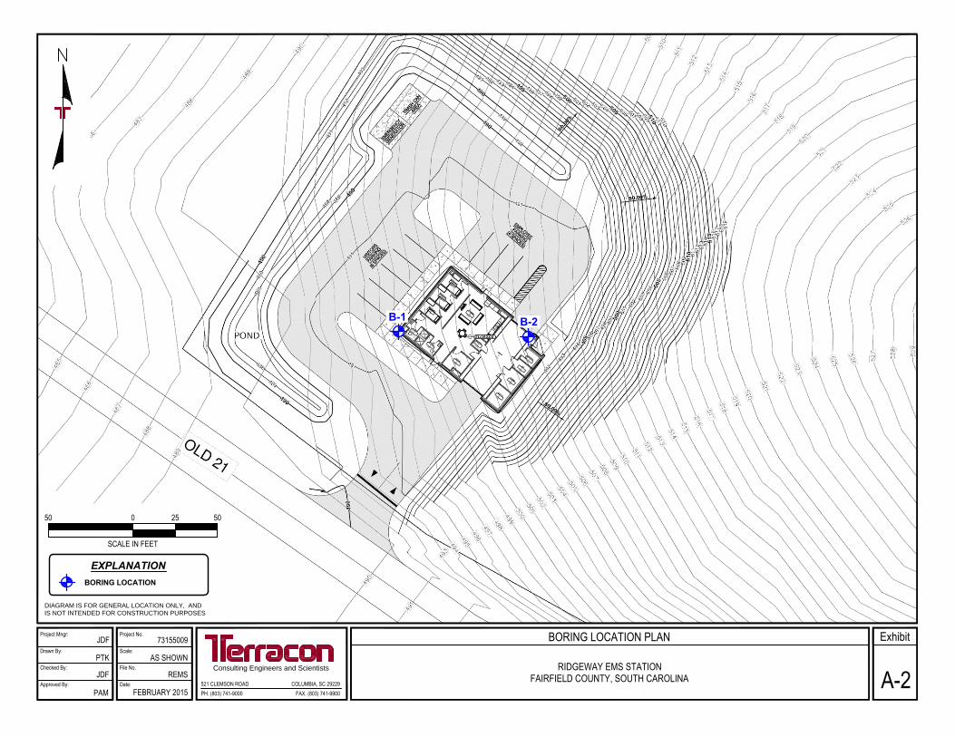
Site layout See the attached Boring Location Plan (Exhibit A-2)
Structures The EMS station will be a 2,400 s.f., single-story building with one
interior parking bay for the EMS vehicle.
Building construction The building is understood to be a steel framed structure with a
concrete slab-on-grade.

Geotechnical Engineering Report Ridgeway EMS Station ■ Fairfield County, SC February 17, 2015 ■ Terracon Project No. 73155009
Responsive ■ Resourceful ■ Reliable 2
ITEM DESCRIPTION
Finished floor elevation The finished floor elevation will be 492 feet, based on the
provided grading plan.
Maximum loads
The loads were not provided at the time of this report. We have
presumed the following:
Maximum Column Load: less than 50 kips
Maximum Uniform Slab Load:
Truck stall: 300 psf
Other areas: 150 psf
Grading
Based on the provided grading plan, the majority of the site will be
cut to reach the planned grades. Cut depths will be up to 20 feet
with the deepest at the east corner of the site. There will be up to
about 2 feet of cut in the west corner of the site.
Slopes The plans indicate that cut slopes of 2H:1V are planned. The cut
heights will reach about 20 feet.
Retention/detention
A storm water detention/retention pond is planned on the west
side of the site. The depth of the pond will be about 2 feet. It will
primarily be constructed by filling perimeter embankments.
Traffic loading We anticipate moderate-duty concrete/asphalt drives and light-
duty parking stalls.
2.2 Site Location and Description
ITEM DESCRIPTION
Location The site is located on the north side of Old SC Highway 21, just
north of Ridgeway, SC.
Existing improvements The site is currently undeveloped.
Surrounding developments The site is bordered on the north and east by undeveloped land
and to the west by a rural residence.
Current ground cover The site is currently covered by moderate density deciduous
trees.
Existing topography In the general development, site topography slopes downward to
the west from Elevation 520 to 488 feet.
Existing utilities
Power lines are present along Old Highway 21. Underground
telecommunications lines were indicated along the edge of the
pavement of the north side of Old 21. No other utilities were
marked at the time of our exploration.

Geotechnical Engineering Report Ridgeway EMS Station ■ Fairfield County, SC February 17, 2015 ■ Terracon Project No. 73155009
Responsive ■ Resourceful ■ Reliable 3
3.0 SUBSURFACE CONDITIONS
3.1 Geology
The subject site is located in South Carolina’s Piedmont physiographic province. The in-
place chemical and mechanical weathering of the parent sedimentary and metamorphic rock
forms the soils present in this region. A common soil profile includes a surficial clayey or silty
layer transitioning to coarser material at depth. Generally dividing the soil layer from the
bedrock is a very dense layer referred to as “partially weathered rock”. Partially weathered
rock is composed of irregular zones of very dense soil and rock. Partially weathered rock
exhibits standard penetration test values of 100 blows per foot (bpf) or more.
The topography of the underlying bedrock surface and the thickness of the various soil and
weathered rock strata vary greatly in short, horizontal distances because of variation in
mineralogy of the material, previous and present groundwater conditions, and past tectonic
activity (faulting, folding, intrusions, etc.). Further, the presence of boulders and rock
pinnacles is possible within the soil matrix.
3.2 Typical Subsurface Profile
Specific conditions encountered at each boring location are indicated on the individual
boring logs. Stratification boundaries on the boring logs represent the approximate location
of changes in soil types; in-situ, the transition between materials may be gradual. Details for
each of the borings can be found on the boring logs included in Appendix A of this report.
Based on the results of the borings, subsurface conditions on the project site can be
generalized as follows:
Description Approximate Depth to
Bottom of Stratum (feet) Material Encountered Consistency/Density
Surface 2 inches Topsoil N/A
Stratum 1 3 to 5-½
Clayey sand Loose to very dense
Stratum 2 13-½ to 21 Silty sand intermixed with partially weathered rock
(silty sand) Dense to very dense
Stratum 31 21.2 and 23.4
Partially weathered rock (silty sand)
Very dense
Notes: 1. Power auger refusal (presumed top of rock) encountered in Borings B-1 and B-2, respectively.
Laboratory testing of the moderate depth soils (Stratum 2) indicates that the silty sands have
fines contents of about 20 to 26 percent with moisture contents from 5 to 10 percent at the
time of our exploration.

Geotechnical Engineering Report Ridgeway EMS Station ■ Fairfield County, SC February 17, 2015 ■ Terracon Project No. 73155009
Responsive ■ Resourceful ■ Reliable 4
3.3 Groundwater Conditions
Groundwater was not encountered in any of the borings at the time of drilling or when the
borings were checked 24 hours later. These observations represent groundwater conditions
at the time of the field exploration and may not be indicative of other times, or at other
locations.
Groundwater levels can be expected to fluctuate with varying seasonal and weather
conditions. Further, water can perch above the very dense soil and partially weathered rock
layers that comprise the explored strata and expose itself with excavation faces made
through the materials such as is planned for this site.
4.0 RECOMMENDATIONS FOR DESIGN AND CONSTRUCTION
4.1 Geotechnical Considerations
The site is suited for the proposed construction of the planned structure. The building may
be supported by conventional spread footings with tolerable settlement estimates.
The primarily issue at this site will be the presence of high consistency soils and partially
weathered rock within the planned excavation range. The borings indicate a typical
piedmont setting, including several feet of moderate to high consistency soil transitioning to
partially weathered rock and eventually reaching the basement rock. As can be seen in the
boring logs, the thicknesses of the residual soil and partially weathered rock as well as the
depth to rock are somewhat variable. Based on limited data, the rock surface elevations
appear to generally decrease to the west, falling roughly in proportion to the existing ground
surface. From our review of the proposed grading data, it appears that rock could be
encountered by the excavation in the east portion of the pavement areas where excavation
is deepest. Utility trenches may also encounter rock.
Though groundwater was not encountered by the borings, there is the potential for periodic
groundwater seeps from the face of the cut slope due to perched water in the upper soils
above the very dense soils and partially weathered rock layers. This can occur after heavy
or prolonged rain events. It would be prudent to consider providing a ditch along the base of
the cut slope slopes to provide separation from the adjacent pavements and move the water
around the site.
Geotechnical engineering recommendations for foundation and pavement systems and
other earth related phases of the project are outlined below. The recommendations
contained in this report are based upon the results of field and lab testing presented in
Appendix A and Appendix B, respectively, engineering analyses, and our current
understanding of the proposed project.
Geotechnical Engineering Report Ridgeway EMS Station ■ Fairfield County, SC February 17, 2015 ■ Terracon Project No. 73155009
Responsive ■ Resourceful ■ Reliable 5
4.2 Earthwork
The following presents recommendations for site preparation, excavation, subgrade
preparation and placement of engineered fills on the project. The recommendations
presented for design and construction of earth supported elements including foundations,
slabs and pavements are contingent upon following the recommendations outlined in this
section. All grading for the structure should incorporate the limits of the proposed structure
plus five feet beyond proposed perimeter building walls and any exterior columns.
Earthwork on the project should be observed and evaluated by Terracon. The evaluation of
earthwork should include observation and testing of engineered fill, subgrade preparation,
foundation bearing soils, and other geotechnical conditions exposed during the construction
of the project.
4.2.1 Site Preparation
After the area has been timbered and the stumps removed, topsoil, concentrations of large
roots and any other unsuitable materials should be stripped and removed from the
construction area. The stripping should extend at least 5 feet beyond the construction limits.
Clean topsoil may be stockpiled for reuse in landscaped areas or pavement shoulders.
Once the contractor’s stripping activities nears completion, we recommend that our
representative observe the subgrade to identify any remaining pockets of organics or
unsuitable material that should be removed.
The site is moderately to heavily wooded, requiring clearing and grubbing activities to
prepare the fill and shallow cut portions of the construction area for mass grading. Clearing
can, for the most part, be accomplished using conventional equipment. Small potholes and
disturbed areas will be created throughout the subgrade in the course of removing the
stumps and rootmat associated with the trees present at the site. These areas are
sometimes “leveled” in the process of cleaning the site in preparation for grading, generally
without receiving adequate compaction. We recommend that the stump holes associated
with large tree stumps be enlarged to remove any loosened soil and to allow fill placement
and compaction with conventional equipment in the fill and at-grade areas. The resulting
holes should then be backfilled as described in Section 4.2.2 of this report.
4.2.2 Subgrade Preparation
After stripping, the exposed subgrades in the at-grade areas and areas receiving fill should
be proofrolled. Cut areas should be proofrolled after they have been excavated to their
proposed subgrade levels. Proofrolling should be performed with a heavily loaded tandem
axle dump truck or with similar approved construction equipment under the observation of
the Terracon geotechnical engineer. If conditions are found to be unstable, the subgrade
should be undercut to soils that would provide a firm base for the compaction of the
structural fill. The undercut soils should be replaced with compacted structural fill, placed as
Geotechnical Engineering Report Ridgeway EMS Station ■ Fairfield County, SC February 17, 2015 ■ Terracon Project No. 73155009
Responsive ■ Resourceful ■ Reliable 6
described in the “Earthwork” section of this report. Mass fill placement may commence after
proofrolling has been successfully completed.
The exposed subgrade soils will be composed of primarily silty sands which can become
unstable when exposed to construction traffic after periods of inclement weather or during
colder periods of the year. Traffic exposure to wet subgrades can destabilize what would
have been otherwise satisfactory conditions, requiring further repair. As a precaution, we
recommend that once the planned subgrade levels have been achieved, the construction
traffic be rerouted from planned structural areas (building and pavements) after periods of
precipitation to allow them to dry. This should help reduce the amount of subgrade repairs
required later in the project. Positive drainage should be maintained at all times to prevent
ponding of stormwater on exposed subgrades or during the operation life of the structure.
Additionally, when inclement weather is expected or over long holiday weekends, exposed
subgrade soils should be rolled smooth to limit stormwater infiltration into prepared
subgrade soils.
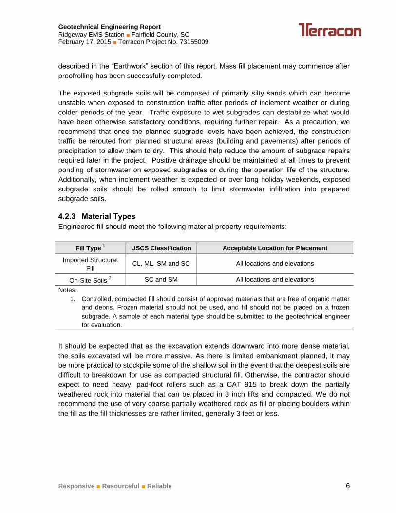
4.2.3 Material Types
Engineered fill should meet the following material property requirements:
Fill Type 1 USCS Classification Acceptable Location for Placement
Imported Structural
Fill CL, ML, SM and SC All locations and elevations
On-Site Soils 2 SC and SM All locations and elevations
Notes:
1. Controlled, compacted fill should consist of approved materials that are free of organic matter
and debris. Frozen material should not be used, and fill should not be placed on a frozen
subgrade. A sample of each material type should be submitted to the geotechnical engineer
for evaluation.
It should be expected that as the excavation extends downward into more dense material,
the soils excavated will be more massive. As there is limited embankment planned, it may
be more practical to stockpile some of the shallow soil in the event that the deepest soils are
difficult to breakdown for use as compacted structural fill. Otherwise, the contractor should
expect to need heavy, pad-foot rollers such as a CAT 915 to break down the partially
weathered rock into material that can be placed in 8 inch lifts and compacted. We do not
recommend the use of very coarse partially weathered rock as fill or placing boulders within
the fill as the fill thicknesses are rather limited, generally 3 feet or less.

Geotechnical Engineering Report Ridgeway EMS Station ■ Fairfield County, SC February 17, 2015 ■ Terracon Project No. 73155009
Responsive ■ Resourceful ■ Reliable 7
4.2.4 Compaction Requirements
ITEM DESCRIPTION
Fill Lift Thickness
8 inches or less in loose thickness when heavy,
self-propelled compaction equipment is used.
4 inches in loose thickness when hand-guided
equipment (i.e. jumping jack or plate compactor) is
used.
Compaction Requirements 1
95% of the material’s standard Proctor maximum
dry unit weight (ASTM D698).
Moisture Content
Within the range of -2 percent and +2 percent of the
optimum moisture content as determined by the
standard Proctor test at the time of placement and
compaction.
1. We recommend that engineered fill be tested for moisture content and compaction during
placement. Should the results of the in-place density tests indicate the specified moisture or
compaction limits have not been met, the area represented by the test should be reworked and
retested as required until the specified moisture and compaction requirements are achieved.
4.2.5 Excavation
Based on the boring data, the mass excavation will encounter high consistency residual
soils (SPT values greater than 30 bpf), partially weathered rock and potentially mass rock.
The use of specialized equipment will be required to excavate these materials. Large, track-
mounted excavating equipment, such as a CAT Model 320, can generally excavate through
a substantial thickness of partially weathered rock. Similarly, large bulldozers, such as a
CAT Model D-8K, equipped with a single-tooth ripper can generally break down partially
weathered rock to sizes that can be loaded and removed. Reaching near to or below the
auger refusal levels will likely require the use of pneumatic tools or explosives (if allowed),
especially in trenches.
Depending on the volume rock encountered, the contractor may consider the use of blasting
techniques. The project site is located within less than 500 feet away from an existing
residence. As such, this structure may be adversely influenced by the shock of blasting. As
such, alternate rock excavation techniques such as the use of pneumatic equipment may
also be considered. A detailed plan of the contractor’s actual method of rock removal should
be submitted to the designers for review and approval.
If rock blasting is needed, we recommend that it be monitored to determine whether any
detrimental impact occurs. Typical monitoring would include seismic accelerometers, blast
monitors and the like at the surrounding existing structures (if possible) or at least at the
property boundaries to measure the vibrations associated with both the signature blasting
and production blasting. Further, we recommend that the owner budget for a comprehensive
precondition survey of the existing structures to be made prior to commencement of any

Geotechnical Engineering Report Ridgeway EMS Station ■ Fairfield County, SC February 17, 2015 ■ Terracon Project No. 73155009
Responsive ■ Resourceful ■ Reliable 8
blasting to provide a baseline of the existing conditions. A precondition survey and vibration
data may be found invaluable to help the owner protect himself from frivolous litigation.
Terracon can aid the designers in developing a plan for these activities.
Because of the presence of substantial partially weathered rock above the planned
excavation base and rock encountered just below that level, we recommend that a rock
definition similar to the one in the following paragraph be included in the project
specifications. Unit rates for mass rock and trench rock should be included in the bid
package to limit disputes, in quantifying the final volume rock excavation.
Any material which cannot either be ripped using a tracked dozer or similar
equipment with a minimum draw bar force of 60,000 pounds pulling a single-
tooth ripper or excavated using a front end loader with a minimum bucket
breakout force of 30,000 pounds should be considered mass rock. Further,
any material that cannot be excavated with a backhoe having a minimum
bucket curling force of not less than 30,000 pounds and outfitted with rock
teeth should be considered trench rock.
It is typical to excavate shallow underground utilities with small to moderate sized backhoes.
This type of equipment will likely be underpowered if those excavations must be made in
partially weathered rock and rock, expected to be present at the planned subgrade levels.
For utility trenches below the building and elsewhere, it may be more practical to over-
excavate these areas with the larger mass excavation equipment below the utility trench
depth and then replace the partially weathered rock with compacted structural fill. The
structural fill could then be more quickly excavated with moderate powered backhoes.
Further, more uniform excavations can be made in the structural fill than in partially
weathered rock. Excavations in partially weathered rock can loosen massive pieces of earth
requiring significantly more time, material, and effort to backfill with structural fill, especially if
irregularly shaped excavations are created.
Groundwater was not encountered in the borings to the auger refusal depths of 21.2 and
23.4 feet below the existing ground surface. However, perched water can collect above and
travel along very hard soil layers and bedrock. If intersected by excavation, the water can
seep into the excavation until depleted, restarting when recharged by surface water
infiltration. As a precaution, we recommend that the civil design include a shallow ditch to
separate the slope and the paved areas. The ditch should be sloped positively drain into an
area drain or other means away from the area. This will provide a means to limit a wet toe
and help limit the introduction of water into the pavement subgrades.
As a minimum, all temporary excavations should be sloped or braced as required by
Occupational Health and Safety Administration (OSHA) regulations to provide stability and
safe working conditions. Temporary excavations will probably be required during grading
operations. The grading contractor, by his contract, is usually responsible for designing and
Geotechnical Engineering Report Ridgeway EMS Station ■ Fairfield County, SC February 17, 2015 ■ Terracon Project No. 73155009
Responsive ■ Resourceful ■ Reliable 9
constructing stable, temporary excavations and should shore, slope or bench the sides of
the excavations as required, to maintain stability of both the excavation sides and bottom.
All excavations should comply with applicable local, state and federal safety regulations,
including the current OSHA Excavation and Trench Safety Standards.
Construction site safety is the sole responsibility of the contractor who controls the means,
methods and sequencing of construction operations. Under no circumstances shall the
information provided herein be interpreted to mean that Terracon is assuming any
responsibility for construction site safety or the contractor's activities; such responsibility
shall neither be implied nor inferred.
4.2.6 Additional Considerations
The geotechnical engineer should be retained during the construction phase of the project to
observe earthwork and to perform necessary tests and observations during subgrade
preparation; proofrolling; placement and compaction of controlled compacted fills; backfilling
of excavations into the completed subgrade, and just prior to construction of building floor
slabs and pavements.
4.3 Foundation Systems
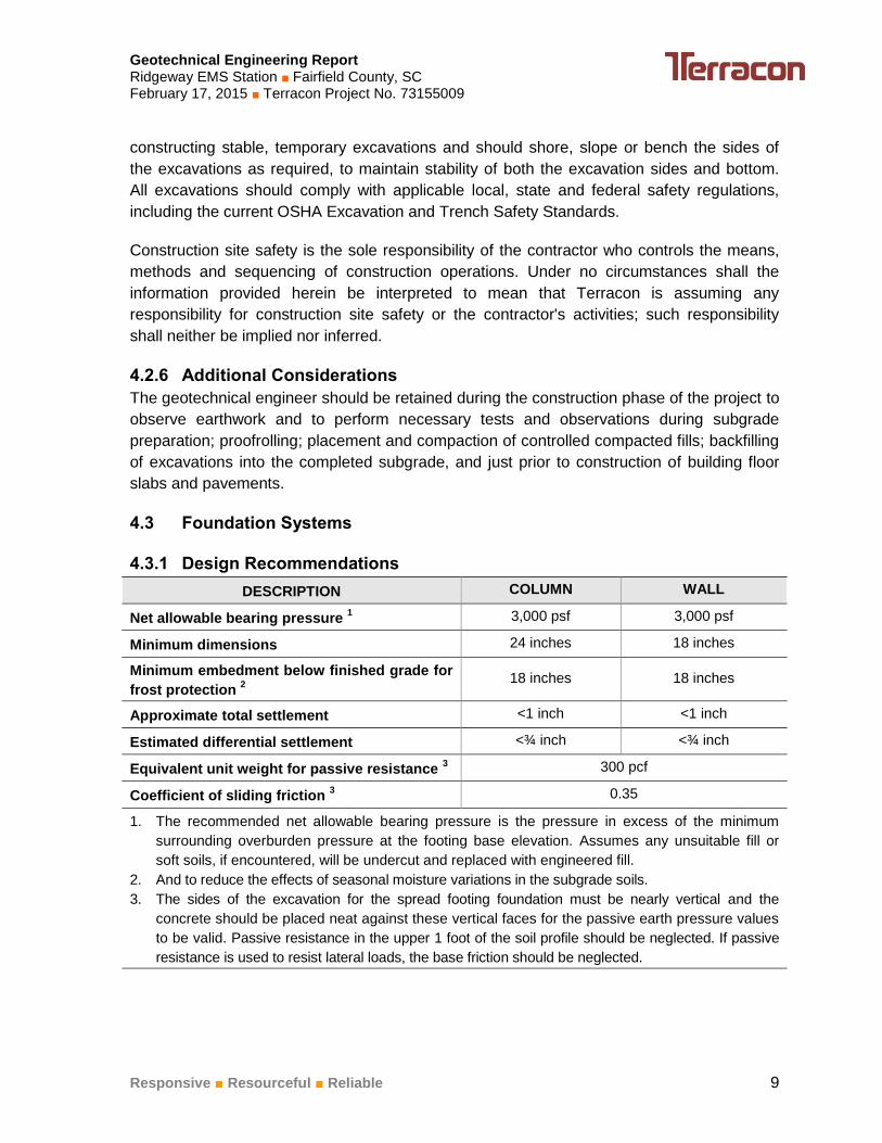
4.3.1 Design Recommendations
DESCRIPTION COLUMN WALL
Net allowable bearing pressure 1 3,000 psf 3,000 psf
Minimum dimensions 24 inches 18 inches
Minimum embedment below finished grade for
frost protection 2
18 inches 18 inches
Approximate total settlement <1 inch <1 inch
Estimated differential settlement <¾ inch <¾ inch
Equivalent unit weight for passive resistance 3 300 pcf
Coefficient of sliding friction 3 0.35
1. The recommended net allowable bearing pressure is the pressure in excess of the minimum
surrounding overburden pressure at the footing base elevation. Assumes any unsuitable fill or
soft soils, if encountered, will be undercut and replaced with engineered fill.
2. And to reduce the effects of seasonal moisture variations in the subgrade soils.
3. The sides of the excavation for the spread footing foundation must be nearly vertical and the
concrete should be placed neat against these vertical faces for the passive earth pressure values
to be valid. Passive resistance in the upper 1 foot of the soil profile should be neglected. If passive
resistance is used to resist lateral loads, the base friction should be neglected.

Geotechnical Engineering Report Ridgeway EMS Station ■ Fairfield County, SC February 17, 2015 ■ Terracon Project No. 73155009
Responsive ■ Resourceful ■ Reliable 10
4.3.2 Construction Recommendations
To check that soil bearing conditions compatible with the design value are achieved, we
recommend that the footing excavations be observed and tested by a Terracon
representative. This evaluation should include performing hand auger borings and dynamic
cone penetration testing (DCP) at different locations and random probing of the surface.
If unsuitable bearing soils are encountered in footing excavations, the excavations should be
extended deeper to suitable soils and the footings could bear directly on these soils at the
lower level or on lean concrete backfill placed in the excavations. The footings could also
bear on properly compacted backfill extending down to the suitable soils. Overexcavation for
compacted backfill placement below footings should extend laterally beyond all edges of the
footings at least 8 inches per foot of overexcavation depth below footing base elevation. The
overexcavation should then be backfilled up to the footing base elevation with compacted
layers of soil backfill placed in lifts of 9 inches or less in loose thickness and compacted to at
least 95 percent of the material's maximum standard effort maximum dry unit weight (ASTM
D 698).
The base of all foundation excavations should be free of water and loose soil prior to placing
concrete. Concrete should be placed soon after excavating to reduce bearing soil
disturbance. If the soils at the bearing level become excessively dry, disturbed or saturated,
or frozen, the affected soil should be removed prior to placing concrete. Place a lean
concrete mud-mat over the bearing soils if the excavations must remain open overnight or
for an extended period of time. It is recommended that the geotechnical engineer be
retained to observe and test the soil foundation bearing materials.
Geotechnical Engineering Report Ridgeway EMS Station ■ Fairfield County, SC February 17, 2015 ■ Terracon Project No. 73155009
Responsive ■ Resourceful ■ Reliable 11
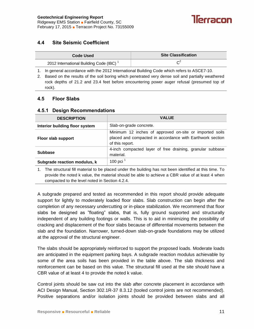
4.4 Site Seismic Coefficient
Code Used Site Classification
2012 International Building Code (IBC) 1 C
2
1. In general accordance with the 2012 International Building Code which refers to ASCE7-10.
2. Based on the results of the soil boring which penetrated very dense soil and partially weathered
rock depths of 21.2 and 23.4 feet before encountering power auger refusal (presumed top of
rock).
4.5 Floor Slabs
4.5.1 Design Recommendations
DESCRIPTION VALUE
Interior building floor system Slab-on-grade concrete.
Floor slab support
Minimum 12 inches of approved on-site or imported soils
placed and compacted in accordance with Earthwork section
of this report.
Subbase 4-inch compacted layer of free draining, granular subbase
material.
Subgrade reaction modulus, k 100 pci 1
1. The structural fill material to be placed under the building has not been identified at this time. To
provide the noted k value, the material should be able to achieve a CBR value of at least 4 when
compacted to the level noted in Section 4.2.4.
A subgrade prepared and tested as recommended in this report should provide adequate
support for lightly to moderately loaded floor slabs. Slab construction can begin after the
completion of any necessary undercutting or in-place stabilization. We recommend that floor
slabs be designed as ”floating” slabs, that is, fully ground supported and structurally
independent of any building footings or walls. This is to aid in minimizing the possibility of
cracking and displacement of the floor slabs because of differential movements between the
slab and the foundation. Narrower, turned-down slab-on-grade foundations may be utilized
at the approval of the structural engineer.
The slabs should be appropriately reinforced to support the proposed loads. Moderate loads
are anticipated in the equipment parking bays. A subgrade reaction modulus achievable by
some of the area soils has been provided in the table above. The slab thickness and
reinforcement can be based on this value. The structural fill used at the site should have a
CBR value of at least 4 to provide the noted k value.
Control joints should be saw cut into the slab after concrete placement in accordance with
ACI Design Manual, Section 302.1R-37 8.3.12 (tooled control joints are not recommended).
Positive separations and/or isolation joints should be provided between slabs and all

Geotechnical Engineering Report Ridgeway EMS Station ■ Fairfield County, SC February 17, 2015 ■ Terracon Project No. 73155009
Responsive ■ Resourceful ■ Reliable 12
foundations, columns or utility lines to allow independent movement. Interior trench backfill
placed beneath slabs should be compacted in accordance with recommendations outlined in
the Earthwork section of this report. Other design and construction considerations, as
outlined in the ACI Design Manual Section 302.1R, are recommended.
The use of a vapor retarder or barrier should be considered beneath concrete slabs on
grade that will be covered with wood, tile, carpet, or other moisture sensitive or impervious
coverings, or when the slab will support equipment sensitive to moisture. When conditions
warrant the use of a vapor retarder/barrier, the slab designer and slab contractor should
refer to ACI 302 and ACI 360 for procedures and cautions regarding the use and placement
of a vapor retarder/barrier.
4.5.2 Construction Considerations
We recommend the area underlying the floor slab be rough graded and then thoroughly
proofrolled with a loaded tandem axle dump truck prior to final grading and placement of base
rock. Particular attention should be paid to high traffic areas that were rutted and disturbed
earlier and to areas where backfilled trenches are located. Areas where unsuitable conditions
are located should be repaired by removing and replacing the affected material with properly
compacted fill. All floor slab subgrade areas should be moisture conditioned and properly
compacted to the recommendations in this report immediately prior to placement of the base
rock and concrete.
On most project sites, the site grading is generally accomplished early in the construction
phase. However as construction proceeds, the subgrade may be disturbed due to utility
excavations, construction traffic, desiccation, rainfall, etc. As a result, the floor slab subgrade
may not be suitable for placement of base rock and concrete and corrective action will be
required to repair the damaged areas.
4.6 Pavements
4.6.1 Design Recommendations
No traffic information has been provided to us at the time of this report. As such, we have
assumed the following:
Pavement design life of 20 years
Light-duty pavement (minimal loading, visitor and employee parking spaces)
Medium-duty pavement (loading below, drives and aprons)
o 30 passenger vehicles per day
o 1 trash truck per week
o 5 delivery vehicles per week
o 10 EMS trucks per week
Geotechnical Engineering Report Ridgeway EMS Station ■ Fairfield County, SC February 17, 2015 ■ Terracon Project No. 73155009
Responsive ■ Resourceful ■ Reliable 13
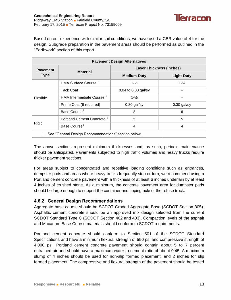
Based on our experience with similar soil conditions, we have used a CBR value of 4 for the
design. Subgrade preparation in the pavement areas should be performed as outlined in the
“Earthwork” section of this report.
Pavement Design Alternatives
Pavement
Type Material
Layer Thickness (inches)
Medium-Duty Light-Duty
Flexible
HMA Surface Course 1 1-½ 1-½
Tack Coat 0.04 to 0.08 gal/sy -
HMA Intermediate Course 1 1-½ -
Prime Coat (If required) 0.30 gal/sy 0.30 gal/sy
Base Course1 8 6
Rigid Portland Cement Concrete
1 5 5
Base Course1 4 4
1. See “General Design Recommendations” section below.
The above sections represent minimum thicknesses and, as such, periodic maintenance
should be anticipated. Pavements subjected to high traffic volumes and heavy trucks require
thicker pavement sections.
For areas subject to concentrated and repetitive loading conditions such as entrances,
dumpster pads and areas where heavy-trucks frequently stop or turn, we recommend using a
Portland cement concrete pavement with a thickness of at least 6 inches underlain by at least
4 inches of crushed stone. As a minimum, the concrete pavement area for dumpster pads
should be large enough to support the container and tipping axle of the refuse truck.
4.6.2 General Design Recommendations
Aggregate base course should be SCDOT Graded Aggregate Base (SCDOT Section 305).
Asphaltic cement concrete should be an approved mix design selected from the current
SCDOT Standard Type C (SCDOT Section 402 and 403). Compaction levels of the asphalt
and Macadam Base Course materials should conform to SCDOT requirements.
Portland cement concrete should conform to Section 501 of the SCDOT Standard
Specifications and have a minimum flexural strength of 550 psi and compressive strength of
4,000 psi. Portland cement concrete pavement should contain about 5 to 7 percent
entrained air and should have a maximum water to cement ratio of about 0.45. A maximum
slump of 4 inches should be used for non-slip formed placement, and 2 inches for slip
formed placement. The compressive and flexural strength of the pavement should be tested

Geotechnical Engineering Report Ridgeway EMS Station ■ Fairfield County, SC February 17, 2015 ■ Terracon Project No. 73155009
Responsive ■ Resourceful ■ Reliable 14
to verify its strength. The concrete should be deposited by truck mixers or agitators and
placed a maximum of 90 minutes from time the water is added to the mix.
To limit the amount of random cracking of the slab due to drying, shrinkage, or thermal
expansion and contraction of the concrete, we recommend a 15-foot maximum joint
spacing. They should be laid out as square as possible. In heavy-duty and dumpster pad
areas, we further recommend that the pavement sections be reinforced with 6-inch by 12-
inch, D5 x D3 deformed welded wire fabric. Note that the heavier steel should be in the
longitudinal direction. The reinforcing wire fabric should be placed just slightly above the
mid-depth of the slab.
Transitions from dissimilar paving materials should be thickened and then tapered to the
design section within about 5 feet. Isolation joints should be used at penetrations within the
paving and at the termination of the paving to allow free relative movement. Polyurethane,
self-leveling, elastomeric joint sealant should be used to seal all joints within the concrete
pavement to limit the flow of water to the underlying subgrade.
Construction joints should be designed as butt joints. They should be reinforced with A615
Grade 40 smooth steel dowels for load transfer while holding adjacent panels in plane and
allowing for longitudinal expansion and contraction. The dowels should be placed at the mid-
height of the slab and placed perpendicular to the panel edge, both vertically and
horizontally. One end should be lightly greased or sleeved to break the concrete bond and
allow free inter-panel movement.
4.6.3 Construction Considerations
Pavement subgrades prepared early in the project should be carefully evaluated as the time
for pavement construction approaches. We recommend the pavement areas be rough
graded and then thoroughly proofrolled with a loaded tandem-axle dump truck. Particular
attention should be paid to high traffic areas that were rutted and disturbed and to areas
where backfilled trenches are located. Areas where unsuitable conditions are located should
be repaired by replacing the materials with properly compacted fill.
The pavement subgrade may have sections that consist of very coarse partially weathered
rock. If large pieces of loosened material are present, they should be removed and replaced
with compacted structural fill or stone base. If ignored, these areas will tend to shift under
the wheel loads of heavy vehicles and cause the premature failure of the pavement.
Future performance of pavements constructed on the site will be dependent upon
maintaining stable moisture content of the subgrade soils; and, providing for a planned
program of preventative maintenance. The performance of all pavements can be enhanced
by minimizing excess moisture that can reach the subgrade soils. The following
recommendations should be considered at minimum:

Geotechnical Engineering Report Ridgeway EMS Station ■ Fairfield County, SC February 17, 2015 ■ Terracon Project No. 73155009
Responsive ■ Resourceful ■ Reliable 15
Site grading at a minimum 2 percent grade away from the pavements;
Sealing all landscaped areas in, or adjacent to pavements to reduce moisture
migration to subgrade soils;
Placing compacted backfill against the exterior side of curb and gutter; and,
Placing curb, gutter and/or sidewalk directly on subgrade soils without the use of
base course materials.
Preventative maintenance should be planned and provided through an on-going pavement
management program in order to enhance future pavement performance. Preventative
maintenance activities are intended to slow the rate of pavement deterioration, and to
preserve the pavement investment.
Preventative maintenance consists of both localized maintenance (e.g. crack and joint
sealing and patching) and global maintenance (e.g. surface sealing). Preventative
maintenance is usually the first priority when implementing a planned pavement
maintenance program and provides the highest return on investment for pavements. Prior to
implementing any maintenance, additional engineering observation is recommended to
determine the type and extent of preventative maintenance.
5.0 GENERAL COMMENTS
Terracon should be retained to review the final design plans and specifications so
comments can be made regarding interpretation and implementation of our geotechnical
recommendations in the design and specifications. Terracon also should be retained to
provide testing and observation during excavation, grading, foundation and construction
phases of the project.
The analysis and recommendations presented in this report are based upon the data
obtained from the borings performed at the indicated locations and from other information
discussed in this report. This report does not reflect variations that may occur between
borings, across the site, or due to the modifying effects of weather. The nature and extent of
such variations may not become evident until during or after construction. If variations
appear, we should be immediately notified so that further evaluation and supplemental
recommendations can be provided.
The scope of services for this project does not include either specifically or by implication
any environmental or biological (e.g., mold, fungi, bacteria) assessment of the site or
identification or prevention of pollutants, hazardous materials or conditions. If the owner is
concerned about the potential for such contamination or pollution, other studies should be
undertaken.
Geotechnical Engineering Report Ridgeway EMS Station ■ Fairfield County, SC February 17, 2015 ■ Terracon Project No. 73155009
Responsive ■ Resourceful ■ Reliable 16
This report has been prepared for the exclusive use of our client for specific application to
the project discussed and has been prepared in accordance with generally accepted
geotechnical engineering practices. No warranties, either express or implied, are intended or
made. Site safety, excavation support, and dewatering requirements are the responsibility of
others. In the event that changes in the nature, design, or location of the project as outlined
in this report are planned, the conclusions and recommendations contained in this report
shall not be considered valid unless Terracon reviews the changes and either verifies or
modifies the conclusions of this report in writing.

APPENDIX A
FIELD EXPLORATION

DIAGRAM IS FOR GENERAL LOCATION ONLY, AND IS NOT
INTENDED FOR CONSTRUCTION PURPOSES
521 CLEMSON ROAD COLUMBIA, SC 29229
PH. (803) 741-9000 FAX. (803) 741-9900
A-1
Exhibit SITE LOCATION MAP Project Mngr.
Drawn By:
Checked By:
Approved By:
JDF
PTK
JDF
PAM Date:
Project No.
Scale:
File Name:
73155009
N.T.S.
A-1
Feb 2015
RIDGEWAY EMS STATION
FAIRFIELD COUNTY, SOUTH CAROLINA
SITE
Project Mngr:
Approved By:
Checked By:
Drawn By:
Project No.
Scale:
Date:
File No.Consulting Engineers and Scientists
Exhibit
521 CLEMSON ROAD COLUMBIA, SC 29229FAX. (803) 741-9900PH. (803) 741-9000
JDF
PTK
JDF
PAM
73155009
AS SHOWN
REMS
FEBRUARY 2015
BORING LOCATION PLAN
A-2RIDGEWAY EMS STATION
FAIRFIELD COUNTY, SOUTH CAROLINA
DIAGRAM IS FOR GENERAL LOCATION ONLY, AND
IS NOT INTENDED FOR CONSTRUCTION PURPOSES
EXPLANATION
BORING LOCATION
SCALE IN FEET
50 0 25 50
B-1
B-2

Geotechnical Engineering Report Ridgeway EMS Station ■ Fairfield County, SC February 17, 2015 ■ Terracon Project No. 73155009
Responsive ■ Resourceful ■ Reliable Exhibit A-3
Field Exploration Description
Two (2) test borings were drilled at the site on February 4 and 5, 2015. The borings were drilled
to power auger refusal, occurring at depths of 21.1 and 23.4 feet below the ground surface at
the approximate locations shown on the attached Boring Location Plan, Exhibit A-2.
The borings were located in the field by using the proposed site plan and an aerial photograph
of the site, and measuring from existing property lines and site features. The ground surface
elevations at the boring locations were interpolated from the contour lines shown on the
provided topographic plan and are shown on the Boring Logs. The boring locations shown on
the Boring Location Plan and the ground surface elevations shown on the Boring Logs are
approximate and should be considered accurate only to the degree implied by the method of
location.
The test borings were advanced with an ATV-mounted CME-550X drill rig utilizing 3-¼-inch
inside diameter hollow-stem augers. Penetration resistance measurements were obtained by
driving a split-spoon sampler into the subsurface materials with a 140-pound automatic hammer
falling 30 inches. The penetration resistance value is a useful index in estimating the
consistency or relative density of materials encountered. A CME automatic SPT hammer was
used to advance the split-barrel sampler in the borings performed on this site. A greater
efficiency is typically achieved with the automatic hammer compared to the conventional safety
hammer operated with a cathead and rope. Published correlations between the SPT values and
soil properties are based on the lower efficiency cathead and rope method. This higher
efficiency affects the standard penetration resistance blow count (N) value by increasing the
penetration per hammer blow over what would be obtained using the cathead and rope method.
The effect of the automatic hammer's efficiency has been considered in the interpretation and
analysis of the subsurface information for this report.
Continuous lithologic logs of each boring were recorded by our field personnel during the drilling
operations. At selected intervals, samples of the subsurface materials were taken by a driving a
split-spoon sampler.
Representative disturbed soil samples were obtained from the borings and were in sealed
containers and returned to our laboratory where our engineer visually reviewed and classified
them. The purposes of this review are to check the drillers’ field classifications and visually
estimate the soils’ relative constituents (sand, clay, etc.). The soil types and penetrometer
values are shown on the Boring Logs. These records represent our interpretation of the field
conditions based on the driller’s field logs and our engineer’s review of the soil samples. The
lines designating the interfaces between various strata represent approximate boundaries only,
as transitions between materials may be gradual.
Groundwater conditions were evaluated in each boring at the time of site exploration and when
checked again after 24 hours. The boreholes were then backfilled with the auger cuttings.

Geotechnical Engineering Report Ridgeway EMS Station ■ Fairfield County, SC February 17, 2015 ■ Terracon Project No. 73155009
Responsive ■ Resourceful ■ Reliable Exhibit A-3
Our exploration services include storing the collected soil samples and making them available
for inspection for 60 days from the report date. The samples will then be discarded unless
requested otherwise.
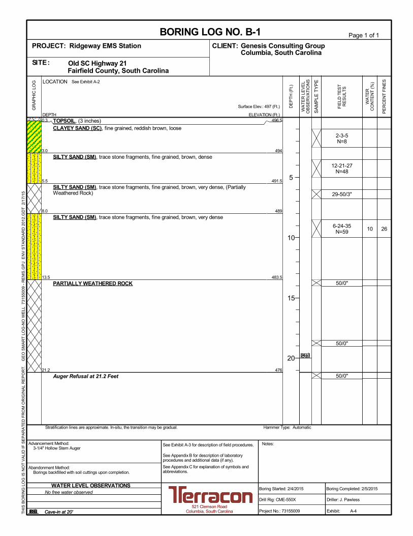
0.3
3.0
5.5
8.0
13.5
21.2
TOPSOIL, (3 inches)CLAYEY SAND (SC), fine grained, reddish brown, loose
SILTY SAND (SM), trace stone fragments, fine grained, brown, dense
SILTY SAND (SM), trace stone fragments, fine grained, brown, very dense, (PartiallyWeathered Rock)
SILTY SAND (SM), trace stone fragments, fine grained, brown, very dense
PARTIALLY WEATHERED ROCK
Auger Refusal at 21.2 Feet
2-3-5N=8
12-21-27N=48
29-50/3"
6-24-35N=59
50/0"
50/0"
50/0"
2610
496.5
494
491.5
489
483.5
476
Hammer Type: AutomaticStratification lines are approximate. In-situ, the transition may be gradual.
LOCATION
DEPTH
GR
AP
HIC
LO
G See Exhibit A-2
TH
IS B
OR
ING
LO
G IS
NO
T V
ALI
D IF
SE
PA
RA
TE
D F
RO
M O
RIG
INA
L R
EP
OR
T.
GE
O S
MA
RT
LO
G-N
O W
ELL
731
550
09 -
RE
MS
.GP
J E
NV
ST
AN
DA
RD
201
2.G
DT
2/1
7/1
5
Page 1 of 1
Advancement Method:3-1/4" Hollow Stem Auger
Abandonment Method:Borings backfilled with soil cuttings upon completion.
521 Clemson RoadColumbia, South Carolina
Notes:
Project No.: 73155009
Drill Rig: CME-550X
Boring Started: 2/4/2015
BORING LOG NO. B-1Genesis Consulting GroupCLIENT:Columbia, South Carolina
Driller: J. Pawless
Boring Completed: 2/5/2015
Exhibit: A-4
See Exhibit A-3 for description of field procedures.
See Appendix B for description of laboratoryprocedures and additional data (if any).
See Appendix C for explanation of symbols andabbreviations.
FIE
LD T
ES
TR
ES
ULT
S
PE
RC
EN
T F
INE
S
WA
TE
RC
ON
TE
NT
(%
)
Surface Elev.: 497 (Ft.)
ELEVATION (Ft.)
SA
MP
LE T
YP
E
WA
TE
R L
EV
EL
OB
SE
RV
AT
ION
S
DE
PT
H (
Ft.)
5
10
15
20
Cave-in at 20'Cave-in at 20'
WATER LEVEL OBSERVATIONSNo free water observed
PROJECT: Ridgeway EMS Station
SITE: Old SC Highway 21 Fairfield County, South Carolina
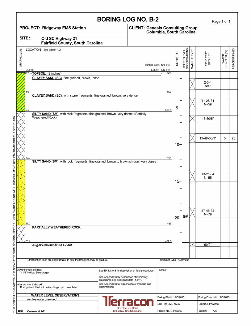
0.2
3.0
5.5
12.0
21.0
23.4
TOPSOIL, (2 inches)CLAYEY SAND (SC), fine grained, brown, loose
CLAYEY SAND (SC), with stone fragments, fine grained, brown, very dense
SILTY SAND (SM), with rock fragments, fine grained, brown, very dense, (PartiallyWeathered Rock)
SILTY SAND (SM), with rock fragments, fine grained, brown to brownish gray, very dense
PARTIALLY WEATHERED ROCK
Auger Refusal at 23.4 Feet
2-3-4N=7
11-28-31N=59
18-50/5"
13-49-50/3"
13-21-34N=55
57-45-34N=79
50/0"
205
506
503
500.5
494
485
482.5
Hammer Type: AutomaticStratification lines are approximate. In-situ, the transition may be gradual.
LOCATION
DEPTH
GR
AP
HIC
LO
G See Exhibit A-2
TH
IS B
OR
ING
LO
G IS
NO
T V
ALI
D IF
SE
PA
RA
TE
D F
RO
M O
RIG
INA
L R
EP
OR
T.
GE
O S
MA
RT
LO
G-N
O W
ELL
731
550
09 -
RE
MS
.GP
J E
NV
ST
AN
DA
RD
201
2.G
DT
2/1
7/1
5
Page 1 of 1
Advancement Method:3-1/4" Hollow Stem Auger
Abandonment Method:Borings backfilled with soil cuttings upon completion.
521 Clemson RoadColumbia, South Carolina
Notes:
Project No.: 73155009
Drill Rig: CME-550X
Boring Started: 2/5/2015
BORING LOG NO. B-2Genesis Consulting GroupCLIENT:Columbia, South Carolina
Driller: J. Pawless
Boring Completed: 2/5/2015
Exhibit: A-5
See Exhibit A-3 for description of field procedures.
See Appendix B for description of laboratoryprocedures and additional data (if any).
See Appendix C for explanation of symbols andabbreviations.
FIE
LD T
ES
TR
ES
ULT
S
PE
RC
EN
T F
INE
S
WA
TE
RC
ON
TE
NT
(%
)
Surface Elev.: 506 (Ft.)
ELEVATION (Ft.)
SA
MP
LE T
YP
E
WA
TE
R L
EV
EL
OB
SE
RV
AT
ION
S
DE
PT
H (
Ft.)
5
10
15
20
Cave-in at 20'Cave-in at 20'
WATER LEVEL OBSERVATIONSNo free water observed
PROJECT: Ridgeway EMS Station
SITE: Old SC Highway 21 Fairfield County, South Carolina

APPENDIX B
LABORATORY TESTING

Geotechnical Engineering Report Ridgeway EMS Station ■ Fairfield County, SC February 17, 2015 ■ Terracon Project No. 73155009
Responsive ■ Resourceful ■ Reliable Exhibit B-1
Laboratory Testing Description
Samples retrieved during the field exploration were taken to the laboratory for further
observation by the project geotechnical engineer and were classified in accordance with the
Unified Soil Classification System (USCS) described in Appendix C. At that time, the field
descriptions were confirmed or modified as necessary and an applicable laboratory testing
program was formulated to determine engineering properties of the subsurface materials.
Laboratory tests were conducted on selected soil samples and the test results are presented in
this appendix. The laboratory test results were used for the geotechnical engineering analyses,
and the development of foundation and earthwork recommendations. Laboratory tests were
performed in general accordance with the applicable ASTM, local or other accepted standards.
Selected soil samples obtained from the site were tested for the following engineering
properties:
Percent Fines ASTM D1140-06 Moisture Content Determination ASTM D2216-10
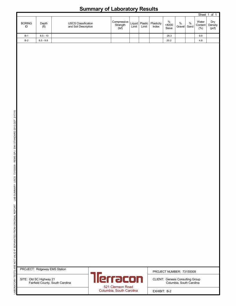
Sheet 1 of 1
Summary of Laboratory Results
DryDensity
(pcf)
WaterContent
(%)
BORINGID
CompressiveStrength
(tsf)
%<#200Sieve
LiquidLimit
USCS Classificationand Soil Description
Depth(ft)
PlasticLimit
PlasticityIndex
%Gravel
%Sand
521 Clemson RoadColumbia, South Carolina
PROJECT NUMBER: 73155009
CLIENT: Genesis Consulting Group Columbia, South Carolina
EXHIBIT: B-2
LAB
OR
AT
OR
Y T
ES
TS
AR
E N
OT
VA
LID
IF S
EP
AR
AT
ED
FR
OM
OR
IGIN
AL
RE
PO
RT
. L
AB
SU
MM
AR
Y:
US
CS
731
5500
9 -
RE
MS
.GP
J E
NV
ST
AN
DA
RD
201
2.G
DT
2/1
7/1
5
B-1 8.5 - 10 26.3 9.8
B-2 8.5 - 9.8 20.2 4.8
PROJECT: Ridgeway EMS Station
SITE: Old SC Highway 21 Fairfield County, South Carolina

APPENDIX C
SUPPORTING DOCUMENTS
TraceWithModifier
Water Level Aftera Specified Period of Time
GRAIN SIZE TERMINOLOGYRELATIVE PROPORTIONS OF SAND AND GRAVEL
TraceWithModifier
Standard Penetration orN-Value
Blows/Ft.
Descriptive Term(Consistency)
Loose
Very Stiff
Exhibit C-1
Standard Penetration orN-Value
Blows/Ft.
Ring SamplerBlows/Ft.
Ring SamplerBlows/Ft.
Medium Dense
Dense
Very Dense
0 - 1 < 3
4 - 9 2 - 4 3 - 4
Medium-Stiff 5 - 9
30 - 50
WA
TE
R L
EV
EL
Auger
Shelby Tube
Ring Sampler
Grab Sample
8 - 15
Split Spoon
Macro Core
Rock Core
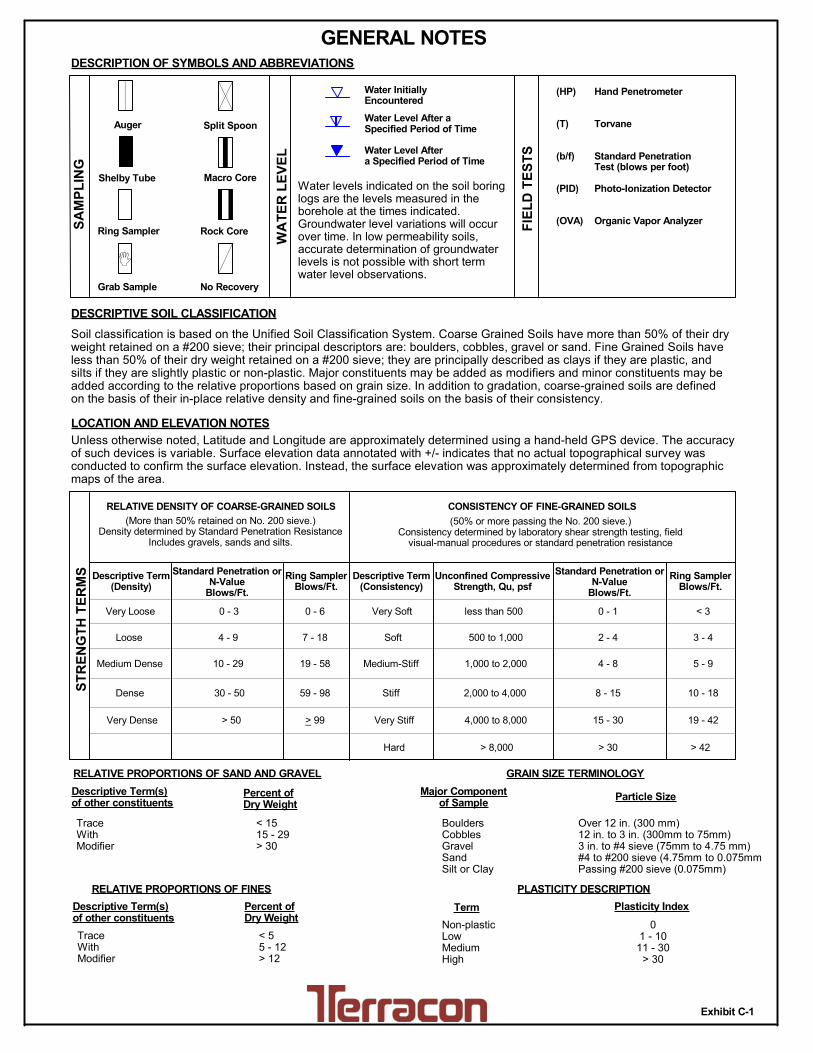
PLASTICITY DESCRIPTION
Term
< 1515 - 29> 30
Descriptive Term(s)of other constituents
Water InitiallyEncountered
Water Level After aSpecified Period of Time
Major Componentof Sample
Percent ofDry Weight
(More than 50% retained on No. 200 sieve.)Density determined by Standard Penetration Resistance
Includes gravels, sands and silts.
Hard
Very Loose 0 - 3 0 - 6 Very Soft
7 - 18 Soft
10 - 29 19 - 58
59 - 98 Stiff
less than 500
500 to 1,000
1,000 to 2,000
2,000 to 4,000
4,000 to 8,000> 99
LOCATION AND ELEVATION NOTES
SA
MP
LIN
G
FIE
LD
TE
ST
S
(HP)
(T)
(b/f)
(PID)
(OVA)
DESCRIPTION OF SYMBOLS AND ABBREVIATIONS
Descriptive Term(Density)
Non-plasticLowMediumHigh
BouldersCobblesGravelSandSilt or Clay
10 - 18
> 50 15 - 30 19 - 42
> 30 > 42
_
Hand Penetrometer
Torvane
Standard PenetrationTest (blows per foot)
Photo-Ionization Detector
Organic Vapor Analyzer
Water levels indicated on the soil boringlogs are the levels measured in theborehole at the times indicated.Groundwater level variations will occurover time. In low permeability soils,accurate determination of groundwaterlevels is not possible with short termwater level observations.
CONSISTENCY OF FINE-GRAINED SOILS
(50% or more passing the No. 200 sieve.)Consistency determined by laboratory shear strength testing, field
visual-manual procedures or standard penetration resistance
DESCRIPTIVE SOIL CLASSIFICATION
> 8,000
Unless otherwise noted, Latitude and Longitude are approximately determined using a hand-held GPS device. The accuracyof such devices is variable. Surface elevation data annotated with +/- indicates that no actual topographical survey wasconducted to confirm the surface elevation. Instead, the surface elevation was approximately determined from topographicmaps of the area.
Soil classification is based on the Unified Soil Classification System. Coarse Grained Soils have more than 50% of their dryweight retained on a #200 sieve; their principal descriptors are: boulders, cobbles, gravel or sand. Fine Grained Soils haveless than 50% of their dry weight retained on a #200 sieve; they are principally described as clays if they are plastic, andsilts if they are slightly plastic or non-plastic. Major constituents may be added as modifiers and minor constituents may beadded according to the relative proportions based on grain size. In addition to gradation, coarse-grained soils are definedon the basis of their in-place relative density and fine-grained soils on the basis of their consistency.
Plasticity Index
01 - 1011 - 30
> 30
RELATIVE PROPORTIONS OF FINES
Descriptive Term(s)of other constituents
Percent ofDry Weight
< 55 - 12> 12
No Recovery
RELATIVE DENSITY OF COARSE-GRAINED SOILS
Particle Size
Over 12 in. (300 mm)12 in. to 3 in. (300mm to 75mm)3 in. to #4 sieve (75mm to 4.75 mm)#4 to #200 sieve (4.75mm to 0.075mmPassing #200 sieve (0.075mm)
ST
RE
NG
TH
TE
RM
S Unconfined CompressiveStrength, Qu, psf
4 - 8
GENERAL NOTES

Exhibit C-2
UNIFIED SOIL CLASSIFICATION SYSTEM
Criteria for Assigning Group Symbols and Group Names Using Laboratory Tests A
Soil Classification
Group
Symbol Group Name
B
Coarse Grained Soils:
More than 50% retained
on No. 200 sieve
Gravels:
More than 50% of
coarse fraction retained
on No. 4 sieve
Clean Gravels:
Less than 5% fines C
Cu 4 and 1 Cc 3 E
GW Well-graded gravel F
Cu 4 and/or 1 Cc 3 E
GP Poorly graded gravel F
Gravels with Fines:
More than 12% fines C
Fines classify as ML or MH GM Silty gravel F,G,H
Fines classify as CL or CH GC Clayey gravel F,G,H
Sands:
50% or more of coarse
fraction passes No. 4
sieve
Clean Sands:
Less than 5% fines D
Cu 6 and 1 Cc 3 E
SW Well-graded sand I
Cu 6 and/or 1 Cc 3 E
SP Poorly graded sand I
Sands with Fines:
More than 12% fines D
Fines classify as ML or MH SM Silty sand G,H,I
Fines classify as CL or CH SC Clayey sand G,H,I
Fine-Grained Soils:
50% or more passes the
No. 200 sieve
Silts and Clays:
Liquid limit less than 50
Inorganic: PI 7 and plots on or above “A” line
J CL Lean clay
K,L,M
PI 4 or plots below “A” line J ML Silt
K,L,M
Organic: Liquid limit - oven dried
0.75 OL Organic clay
K,L,M,N
Liquid limit - not dried Organic silt K,L,M,O
Silts and Clays:
Liquid limit 50 or more
Inorganic: PI plots on or above “A” line CH Fat clay
K,L,M
PI plots below “A” line MH Elastic Silt K,L,M
Organic: Liquid limit - oven dried
0.75 OH Organic clay
K,L,M,P
Liquid limit - not dried Organic silt K,L,M,Q
Highly organic soils: Primarily organic matter, dark in color, and organic odor PT Peat
A Based on the material passing the 3-inch (75-mm) sieve
B If field sample contained cobbles or boulders, or both, add “with cobbles
or boulders, or both” to group name. C
Gravels with 5 to 12% fines require dual symbols: GW-GM well-graded
gravel with silt, GW-GC well-graded gravel with clay, GP-GM poorly
graded gravel with silt, GP-GC poorly graded gravel with clay. D
Sands with 5 to 12% fines require dual symbols: SW-SM well-graded
sand with silt, SW-SC well-graded sand with clay, SP-SM poorly graded
sand with silt, SP-SC poorly graded sand with clay
E Cu = D60/D10 Cc =
6010
2
30
DxD
)(D
F If soil contains 15% sand, add “with sand” to group name.
G If fines classify as CL-ML, use dual symbol GC-GM, or SC-SM.
H If fines are organic, add “with organic fines” to group name.
I If soil contains 15% gravel, add “with gravel” to group name.
J If Atterberg limits plot in shaded area, soil is a CL-ML, silty clay.
K If soil contains 15 to 29% plus No. 200, add “with sand” or “with gravel,”
whichever is predominant. L
If soil contains 30% plus No. 200 predominantly sand, add “sandy” to
group name. M
If soil contains 30% plus No. 200, predominantly gravel, add
“gravelly” to group name. N
PI 4 and plots on or above “A” line. O
PI 4 or plots below “A” line. P
PI plots on or above “A” line. Q
PI plots below “A” line.