geotechnical engineering report - oakton community · pdf filegeotechnical engineering report...
TRANSCRIPT

Responsive ■ Resourceful ■ Reliable
Geotechnical Engineering Report Science & Health Careers Center
Oakton Community College
Des Plaines, Illinois
October 4, 2011
Terracon Project No. 11115059
Prepared for:
Oakton Community College
Des Plaines, Illinois
Prepared by:
Terracon Consultants, Inc.
Naperville, Illinois


Responsive ■ Resourceful ■ Reliable
TABLE OF CONTENTS
Page
EXECUTIVE SUMMARY ............................................................................................................. i
1.0 INTRODUCTION .............................................................................................................. 1
2.0 PROJECT INFORMATION ............................................................................................... 1
2.1 Project Description ............................................................................................... 2
2.2 Site Location and Description ............................................................................... 3
3.1 Typical Profile ....................................................................................................... 3
3.2 Water Level Observations ..................................................................................... 4
4.0 RECOMMENDATIONS FOR DESIGN AND CONSTRUCTION ........................................ 5
4.1 Geotechnical Considerations ................................................................................ 5
4.2 Earthwork .............................................................................................................. 6
4.2.1 Site Preparation......................................................................................... 6
4.2.2 Engineered Fill Material Requirements ...................................................... 7
4.2.3 Fill Placement and Compaction Requirements .......................................... 7
4.2.4 Earthwork Construction Considerations ..................................................... 8
4.2.5 Grading and Drainage ............................................................................... 9
4.3 Drilled Shaft Foundations .....................................................................................10
4.3.2 Drilled Shaft Foundation Design Recommendations .................................10
4.3.2 Drilled Shaft Foundation Construction Considerations ..............................12
4.4 Floor Slab ............................................................................................................13
4.4.1 Floor Slab Design Recommendations ......................................................13
4.4.2 Floor Slab Construction Considerations ...................................................14
4.5 Below Grade Walls ..............................................................................................14
4.5.1 Lateral Earth Pressures ............................................................................14
4.5.2 Subsurface Drainage ................................................................................16
4.6 Pavements ..........................................................................................................16
4.6.1 Pavement Design Recommendations .......................................................16
4.6.2 Pavement Construction Considerations ....................................................18
4.7 Seismic Site Class ..............................................................................................18
APPENDIX A – FIELD EXPLORATION
Exhibit A-1 Field Exploration Description
Exhibit A-2 Boring Location Plan
Exhibits A-3 to A-21 Boring Logs
Exhibits A-22 & A-23 ReMi Seismic Testing Results
APPENDIX B – LABORATORY TESTING
Exhibit B-1 Laboratory Testing
Exhibits B-2 Chemical Test Results
APPENDIX C – SUPPORTING DOCUMENTS
Exhibit C-1 General Notes
Exhibit C-2 Unified Soil Classification

Geotechnical Engineering Report
Science & Health Careers Center ■ Des Plaines, Illinois October 4, 2011 ■ Terracon Project No. 11115059
Responsive ■ Resourceful ■ Reliable i
EXECUTIVE SUMMARY
The following items represent a brief summary of the findings of our subsurface exploration and
our geotechnical recommendations for the proposed Science & Health Careers Center planned
at Oakton Community College in Des Plaines, Illinois. This summary should be reviewed in
conjunction with the complete report.
Based on the subsurface conditions encountered in the borings, the anticipated structural
loads (600 to 1,000 kip column loads), and the preliminary building plans provided to us at
the time this report was prepared, it is Terracon’s opinion that the proposed 3-story building
should be supported on drilled shaft foundations. Geotechnical recommendations for
design and construction of drilled shaft foundations are provided in this report.
Existing fill materials (comprised primarily of lean clay with variable amounts of sand and
gravel) were encountered to depths of about 2½ to 6 feet below existing surface grades
at most of the boring locations. Based on conditions encountered in the borings, it
appears that some compactive effort was applied to portions of the fill; however, no
documentation regarding placement and compaction of the fill was provided for our
review. If the existing fill will be left in place below slabs, pavements or other features,
additional observation and testing of the existing fill should be performed to reduce the
risk of adverse slab/pavement performance.
The soils encountered in the upper few feet at the boring locations generally consisted of
lean clays with traces of sand and gravel (both fill and native soils). The moisture content
of these soils was relatively high (ranging from about 18 to 31 percent) at many of the
boring locations. Subgrades comprised of clay soils with relatively high moisture
contents often become unstable when they are disturbed and/or subjected to
construction traffic. Therefore, some undercutting or stabilization of the subgrade will
likely be required to facilitate compaction of new engineered fill or to provide a stable
subgrade for grade supported floor slabs and pavements.
A 10-year flood elevation of 634.1 feet and a 100-year flood elevation of 636.5 feet were
indicated on the preliminary plans provided to us. The ground surface elevation at the
building area borings generally ranged from about 632 to 634 feet. Therefore, even
though the depth to water was variable at the boring locations, and water was not
encountered at some boring locations, it is likely that water will be encountered in
excavations at this site. The contractor should anticipate this and plan for the
appropriate dewatering needed to control seepage and facilitate construction.

Geotechnical Engineering Report
Science & Health Careers Center ■ Des Plaines, Illinois October 4, 2011 ■ Terracon Project No. 11115059
Responsive ■ Resourceful ■ Reliable ii
Close monitoring of the construction operations discussed herein will be critical in
achieving the design subgrade support. We therefore recommend that Terracon be
retained to provide observation/testing during this portion of the work.
This summary should be used in conjunction with the entire report for design purposes. It
should be recognized that details were not included or fully developed in this section, and the
report must be read in its entirety for a comprehensive understanding of the items contained
herein. The section titled GENERAL COMMENTS should be read for an understanding of the
report limitations.

Responsive ■ Resourceful ■ Reliable 1
GEOTECHNICAL ENGINEERING REPORT
SCIENCE & HEALTH CAREERS CENTER
OAKTON COMMUNITY COLLEGE
DES PLAINES, ILLINOIS Terracon Project No. 11115059
October 4, 2011
1.0 INTRODUCTION
Terracon Consultants, Inc. (Terracon) has completed a subsurface exploration for the proposed
Science & Health Careers Center planned at the Oakton Community College campus in Des
Plaines, Illinois. Twenty (20) borings were performed at the site to depths ranging from
approximately 10 to 80 feet below the existing ground surface. Boring logs and a Boring Location
Plan are included in Appendix A.
Borings 1 through 12 were located within the proposed new Science & Health Careers Center
building area. Borings 13 through 15 were located near the existing Oakton Community College
building, and were requested to provide preliminary information for a potential future addition to that
building (not addressed in this report). Borings 16 through 18 were performed in the north part of
Parking Lot D (not currently planned for additional development), and Borings 19 and 20 were
performed in the peninsula on the west side of Oakton Lake (where grades may be lowered to
balance the floodplain area and account for the grade increases in the new development).
This report describes the subsurface conditions encountered at the boring locations, presents
the test data, and provides geotechnical engineering recommendations regarding the following
items:
site preparation and earthwork
design and construction of drilled shaft foundations
floor slab subgrade preparation
lateral earth pressures
pavement subgrade preparation
recommended minimum pavement sections
seismic site class
2.0 PROJECT INFORMATION
Project information was provided by Legat Architects and is summarized below.

Geotechnical Engineering Report
Science & Health Careers Center ■ Des Plaines, Illinois October 4, 2011 ■ Terracon Project No. 11115059
Responsive ■ Resourceful ■ Reliable 2
2.1 Project Description
ITEM DESCRIPTION
Site layout See Appendix A, Exhibit A-2 Boring Location Plan
Structure
The proposed building will be a three-story structure located
in the southern part of the existing Parking Lot D. The
building “footprint” is larger in the upper floors due to
overhangs. The plan areas of the first, second and third
floors will be about 24,000, 28,000, and 36,000 square feet,
respectively.
Current grade within most of the building area is at about 633
feet (USGS datum), and the 100-year flood elevation is
approximately 636.5 feet. Therefore, the first floor elevation
is planned to be at about elevation 640.5 feet.
In the west part of the building, fill will be placed above
current grade to develop a subgrade for a slab-on-grade.
In the east part of the building, the first floor slab will be a
structural slab supported on the building’s foundation system,
and the portions of the columns extending below the first floor
level will be screened by a curtain wall that extends to
existing ground level.
A wall with unbalanced backfill is planned at the junction
between the structural slab and slab-on-grade areas of the
building.
Maximum loads
According to the project structural engineer (Harley Ellis
Devereaux), column loads are expected to range from
approximately 600 to 1000 kips.
Maximum allowable settlement
Maximum allowable settlements for the building were not
provided. The following values were assumed:
Columns: 1 inch
Walls: ¾ inch over 40 feet
Pavements
A new parking lot is planned south of the new building, and
some of the existing pavements in Parking Lot D may be
reconstructed.
Grading
Fills of up to 7 feet are expected to develop the floor slab
subgrade in the west part of the building. Cuts/fills of 2 feet
or less are expected in the remainder of the development
area.

Geotechnical Engineering Report
Science & Health Careers Center ■ Des Plaines, Illinois October 4, 2011 ■ Terracon Project No. 11115059
Responsive ■ Resourceful ■ Reliable 3
2.2 Site Location and Description
ITEM DESCRIPTION
Location Oakton Community College campus, 1600 East Golf Road,
Des Plaines, Illinois
Current Site Improvements
Existing pavements are present within the north part of the
proposed new building area. The south part of the proposed
new building area is currently a lawn area.
Existing topography
Based on the site topographic plan prepared by Manhard
Consulting, surface elevations within the proposed new
building area currently range from about 632 to 634 feet.
3.0 SUBSURFACE CONDITIONS
3.1 Typical Profile
Subsurface conditions at each boring location are described on the individual boring logs in
Appendix A. The stratification boundaries shown on the boring logs represent the approximate
depths where changes in material types occur. In-situ, transitions between material types can
be more gradual. Based on the results of the borings, subsurface conditions on the project site
can be generalized as follows:
Description Approximate Depth
to Bottom of Stratum Material Encountered Consistency/Density
Surface 1 1 4 to 18 inches Topsoil / topsoil fill N/A
Surface 2 2 9 to 15 inches
2 to 4 inches of asphalt over 6 to
12 inches of crushed stone
aggregate
N/A
Stratum 1 3 2½ to 6 feet
Fill: lean clay with variable
amounts of sand N/A
Stratum 2 3 to 8 feet Lean clay, trace sand and gravel Medium stiff to stiff
Stratum 3 40 to 80 feet
Lean clay, trace sand and gravel;
with occasional seams/layers of
silty clay, silt and sand
Stiff to very stiff
1. Surface 1 was encountered in Borings 1 through 5 and 16 through 18.
2. Surface 2 was encountered in Borings 7 through 10 and 12.
3. Stratum 1 was encountered in Borings 1 trough 9, 11, 13, 15, and 17 through 20.

Geotechnical Engineering Report
Science & Health Careers Center ■ Des Plaines, Illinois October 4, 2011 ■ Terracon Project No. 11115059
Responsive ■ Resourceful ■ Reliable 4
3.2 Water Level Observations
The borings were observed during and after the completion of drilling for the presence and level
of water. The water level observations are summarized in the following table.
Observed Water Depth (ft)
1
Boring Number While Drilling After Drilling
1 None 61
5 13½ None
8 39 39
9 68½ 30
10 7 11½
11 14 None
12 14½ 12
13 7 None
14 18 None
15 9½ None
16 6 6
1 Below existing grade
Water was not encountered in the remaining borings at the time of our exploration. However,
the absence of water at a boring location does not necessarily mean that the boring terminated
above the subsurface water level. Trapped water could occur within existing fill materials, and
“perched” water could occur above lower permeability soil layers and within seams/layers of silt
or sand. Due to the relatively low permeability of the cohesive soils encountered in the borings,
longer term observations in cased holes or piezometers, sealed from the influence of surface
water, would be required for a better evaluation of the groundwater conditions on this site.
A 10-year flood elevation of 634.1 feet and a 100-year flood elevation of 636.5 feet were
indicated on the preliminary plans provided to us. The ground surface elevation at the building
area borings generally ranged from about 632 to 634 feet. Therefore, even though the depth to
water was variable in the borings, and water was not encountered at some boring locations, it is
likely that water will be encountered in excavations at this site.
Water levels may fluctuate due to seasonal variations in the amount of rainfall, runoff, and other
factors not evident at the time the borings were performed. Trapped or “perched” water could
occur above lower permeability soil layers. Water level fluctuations and perched water should
be considered when developing design and construction plans and specifications for the project.

Geotechnical Engineering Report
Science & Health Careers Center ■ Des Plaines, Illinois October 4, 2011 ■ Terracon Project No. 11115059
Responsive ■ Resourceful ■ Reliable 5
4.0 RECOMMENDATIONS FOR DESIGN AND CONSTRUCTION
4.1 Geotechnical Considerations
Based on the subsurface conditions encountered in the borings, the anticipated structural loads,
and the preliminary building plans provided to us at the time this report was prepared, it is
Terracon’s opinion that the proposed 3-story building should be supported on drilled shaft
foundations. Recommendations for design and construction of drilled shaft foundations bearing in
stiff to very stiff native clay soils are provided in Section 4.3 of this report.
Existing fill materials (comprised primarily of lean clay with variable amounts of sand and gravel)
were encountered to depths of about 2½ to 6 feet below existing surface grades at most of the
boring locations. Based on conditions encountered in the borings, it appears that some
compactive effort was applied to portions of the fill; however, no documentation regarding
placement and compaction of the fill was provided for our review. Since deep foundations
(drilled shafts) are recommended for support of the building’s structural loads, the presence of
existing fill materials to the depths encountered is not expected to affect the foundation design.
The following considerations are provided regarding the impact of the existing fill on new grade
supported building floor slabs and pavements.
If portions of the existing fill will be left in place, the existing fill should be thoroughly observed
and tested before the fill is used to support new slabs and pavements. The existing pavements
in Parking Lot D have been supported on the fill, and these pavements have reportedly
performed in a satisfactory manner for the owner. However, it should be noted that
undocumented fill may contain soft or loose soils or other unsuitable materials; these conditions
may not be disclosed by the widely spaced, small-diameter borings. If these conditions are
present and are not discovered and corrected during construction, larger than normal settlement
resulting in cracking or other damage could occur in slabs, pavements, utility lines and any other
elements supported on or above the existing fill. These risks can be reduced by thorough
observation and testing during construction, but they cannot be eliminated without complete
removal and replacement of the fill. To reduce the risk of adverse performance and provide
more uniform support for slabs and pavements, any fill materials that will be left in place below
new slab and pavements should be observed and tested. Where unsuitable conditions are
observed, the materials should improved by scarification/compaction or be removed and
replaced with engineered fill that is placed and compacted as recommended in this report.
The soils encountered in the upper few feet at the boring locations generally consisted of lean clays
with traces of sand and gravel (both fill and native soils). The moisture content of these soils was
relatively high (ranging from about 18 to 31 percent) at many of the boring locations. Subgrades
comprised of clay soils with relatively high moisture contents often become unstable when they
are disturbed and/or subjected to construction traffic. Therefore, some undercutting or

Geotechnical Engineering Report
Science & Health Careers Center ■ Des Plaines, Illinois October 4, 2011 ■ Terracon Project No. 11115059
Responsive ■ Resourceful ■ Reliable 6
stabilization of the subgrade will likely be required to facilitate compaction of new engineered fill
or to provide a stable subgrade for floor slabs or pavements.
A 10-year flood elevation of 634.1 feet and a 100-year flood elevation of 636.5 feet were
indicated on the preliminary plans provided to us. The ground surface elevation at the building
area borings generally ranged from about 632 to 634 feet. Therefore, even though the depth to
water was variable at the boring locations, and water was not encountered at some boring
locations, it is likely that water will be encountered in excavations at this site. The contractor
should anticipate this and plan for the appropriate dewatering needed to control seepage and
facilitate construction.
Our recommendations for earthwork, design and construction of drilled shaft foundations, lateral
earth pressures for below grade walls, subgrade preparation for grade supported floor slabs, and
pavements for the facility are presented in the following sections.
4.2 Earthwork
Recommendations for site preparation, excavation, subgrade preparation and placement of
engineered fill for the project are provided below.
4.2.1 Site Preparation
Pavements, curbs, sidewalks and other existing improvements that are currently present within
proposed construction areas should be removed. Existing utilities that would interfere with the
proposed new construction should be removed or relocated. Excavations created by
demolition/removal of existing improvements should be observed and evaluated prior to
placement of new fill. The demolition contractor should be aware of project requirements for
backfilling so that removal of recently placed fill materials and replacement of under controlled
conditions is not necessary when building construction commences.
Organic soils, root systems, and other unsuitable materials should also be stripped from
proposed construction areas during site preparation. The drill crew noted a relatively thick
topsoil layer (up to 18 inches thick) at some of the boring locations. However, since samples of
this layer were not obtained and organic content tests were not performed, additional
exploration (such as shallow test pits) may be advisable so the earthwork contractor can
evaluate the required stripping depth. Organic soils removed during site preparation could be
utilized as fill for landscaped areas, but these materials should not be used as fill beneath the
proposed building or pavement areas.
The soils exposed following removal of existing improvements should be observed and tested
prior to placing new engineered fill and/or construction of new slabs and pavements. The
exposed soils should be proofrolled using a loaded tandem-axle dump truck with a gross weight
of at least 25 tons, or similarly loaded equipment. Areas that display excessive deflection

Geotechnical Engineering Report
Science & Health Careers Center ■ Des Plaines, Illinois October 4, 2011 ■ Terracon Project No. 11115059
Responsive ■ Resourceful ■ Reliable 7
(pumping) or rutting during proofroll operations should be improved by scarification/compaction
or by removal and replacement with engineered fill.
4.2.2 Engineered Fill Material Requirements
Engineered fill should meet the following material property requirements:
Fill Type 1 USCS Classification Acceptable Location for Placement
4
Cohesive 2 CL, CL-ML Below/adjacent to slabs and pavements
Granular GW, GP, GM, GC
SW, SP, SM, SC Below/adjacent to slabs and pavements
Unsuitable CH, MH, OL, OH, PT Non-structural locations
1. Engineered fill should consist of approved materials that are free of organic matter and debris.
Cohesive fill materials should have liquid limit less than 45 and a plasticity index less than 20;
cohesive soils that do not meet these criteria should be considered “unsuitable.” Frozen material
should not be used, and fill should not be placed on a frozen subgrade. A sample of each material
type should be submitted to the geotechnical engineer for evaluation prior to use on this site.
2. Based on visual and tactile examination of recovered soil samples and the results of the laboratory
tests, most of the on-site lean clay soils (native and fill) would meet the criteria for engineered fill.
However, any organic materials, rock fragments larger than 3 inches, and other unsuitable materials
should be removed prior to use of the existing fill materials in new fill sections.
3. A large portion of the on-site lean clay soils had moisture contents of 18 percent or greater.
Significant drying (if weather conditions are favorable) and/or incorporation of a chemical modifier
(such as lime or Class C fly ash) will be required to reduce the moisture contents of wet soils so
they can be properly compacted in new fill sections. In our experience, modified Proctor optimum
moisture contents in the range of 11 to 14 percent would be expected for these types of soils.
4. Since deep foundations (drilled shafts) are recommended, recommendations for materials to be
placed below/adjacent to foundations are not provided. However, any backfill for below grade walls
or adjacent to grade beams should meet the material and compaction requirements recommended
in this section and Section 4.2.3.
4.2.3 Fill Placement and Compaction Requirements
Item Description
Fill Lift Thickness
9 inches or less in loose thickness when heavy, self-
propelled compaction equipment is used.
4 to 6 inches in loose thickness when hand-guided
equipment (i.e., a jumping jack or plate compactor) is
used.
Minimum Compaction Requirement 1, 2
Below Slabs-on-grade, Upper 12 inches
of Areas to be Paved
95% of the material’s modified Proctor maximum dry
density (ASTM D 1557). This level of compaction should
extend beyond the edges of footings at least 8 inches for
every foot of fill placed below the foundation base
elevation.

Geotechnical Engineering Report
Science & Health Careers Center ■ Des Plaines, Illinois October 4, 2011 ■ Terracon Project No. 11115059
Responsive ■ Resourceful ■ Reliable 8
Item Description
Minimum Compaction Requirement 1, 2
Below 12 Inches in Areas to be Paved,
Landscaped Areas
90% of the material’s maximum modified Proctor dry
density (ASTM D 1557)
Moisture Content of Cohesive Soil 4 -2% to +3% of modified Proctor optimum (ASTM D 1557)
Moisture Content of Granular Material 3 Workable moisture levels
1. We recommend that each lift of fill be tested for moisture content and compaction prior to the
placement of additional fill or concrete. If the results of the in-place density tests indicate the
specified moisture or compaction limits have not been met, the area represented by the test
should be reworked and retested as required until the specified moisture and compaction
requirements are achieved.
2. If granular material is a coarse sand or gravel, is of a uniform size, or has a low fines content,
compaction comparison to relative density (ASTM D 4253/4254) may be more appropriate.
3. The gradation of a granular material affects its stability and the moisture content required for
proper compaction. Moisture levels should be maintained to achieve compaction without bulking
during placement or pumping when proofrolled.
4. Significant drying of the on-site clay soils will be required to reach the moisture content range
recommended for compaction.
4.2.4 Earthwork Construction Considerations
The geotechnical engineer should be retained during the construction phase of the project to
observe earthwork and to perform necessary tests and observations during demolition/removal
of existing improvements, subgrade preparation, proofrolling, placement and compaction of
compacted engineered fills, backfilling of excavations, and just prior to construction of grade
supported building floor slabs.
Clay soils with high moisture contents (greater than 18 percent) were encountered within the
upper several feet of the soil profile at most of the boring locations. These soils will be sensitive to
disturbance from construction activities, particularly if further wetted by surface water or seepage.
Therefore, it is anticipated that some areas of the site will become unstable during proofrolling and
construction operations. The amount of stabilization required would be highly dependent upon
weather conditions during construction and drainage measures implemented during mass grading
and construction.
Some means of subgrade stabilization will likely be required to facilitate construction. In general
(weather permitting), scarifying, drying and recompacting the exposed subgrades is expected to
be the most economical means of improving these soils prior to placing new fill. However, this
option is typically less effective where soft/wet soils are thicker than about one foot, and this
method is also dependent on weather conditions. Alternatives for subgrade stabilization could
include undercutting unsuitable (wet, low strength, and/or disturbed) soils followed by the addition

Geotechnical Engineering Report
Science & Health Careers Center ■ Des Plaines, Illinois October 4, 2011 ■ Terracon Project No. 11115059
Responsive ■ Resourceful ■ Reliable 9
of crushed stone aggregate (typically on the order of 12 to 18 inches) to improve subgrade
stability, or the incorporation of a chemical additive such as lime, Class C fly ash or portland
cement. The need for stabilization and most appropriate type of stabilization will be dependent
upon soil, groundwater and weather conditions, the construction schedule and methods of
construction that will be used.
As noted above, the 10-year and 100-year flood elevations are reportedly above current surface
grades within the proposed building area. Therefore, it is likely that water will be encountered in
excavations at this site. Seepage should be expected in excavations for this project, and the
contractor is responsible for employing appropriate dewatering methods to control seepage and
facilitate construction. In our experience, dewatering of excavations in clay soils can typically be
accomplished using sump pits and pumps. If excessive seepage from sand seams/layers is
encountered, a more extensive dewatering system (such as multiple sump pits/pumps or well
points) could be required.
Care should be taken to avoid disturbance of prepared subgrades. Unstable subgrade
conditions could develop during general construction operations, particularly if the soils are
wetted and/or subjected to repetitive construction traffic. New fill compacted above optimum
moisture content or that accumulates water during construction can also become disturbed
under construction equipment. Construction traffic over the completed subgrade should be
avoided to the extent practical. If the subgrade becomes saturated, desiccated, or disturbed,
the affected materials should either be scarified and compacted or be removed and replaced.
Subgrades should be observed and tested prior to construction of slabs and pavements.
As a minimum, excavations should be performed in accordance with OSHA 29 CFR, Part 1926,
Subpart P, “Excavations” and its appendices, and in accordance with any applicable local, state,
and federal safety regulations. The contractor should be aware that slope height, slope
inclination, and excavation depth should in no instance exceed those specified by these safety
regulations. Flatter slopes than those dictated by these regulations may be required depending
upon the soil conditions encountered and other external factors. These regulations are strictly
enforced and if they are not followed, the owner, contractor, and/or earthwork and utility
subcontractor could be liable and subject to substantial penalties. Under no circumstances
should the information provided in this report be interpreted to mean that Terracon is
responsible for construction site safety or the contractor’s activities. Construction site safety is
the sole responsibility of the contractor who shall also be solely responsible for the means,
methods, and sequencing of the construction operations.
4.2.5 Grading and Drainage
During construction, grades should be developed to direct surface water flow away from or
around the site. Exposed subgrades should be sloped to provide positive drainage so that
saturation of subgrades is avoided. Surface water should not be permitted to accumulate on the
site.
Geotechnical Engineering Report
Science & Health Careers Center ■ Des Plaines, Illinois October 4, 2011 ■ Terracon Project No. 11115059
Responsive ■ Resourceful ■ Reliable 10
Final grades should slope away from the building to promote rapid surface drainage.
Accumulation of water adjacent to the building could contribute to significant moisture increases
in the subgrade soils and subsequent softening/settlement. Roof drains should discharge into a
storm sewer or several feet away from the building.
4.3 Drilled Shaft Foundations
Based on the anticipated column loads (600 to 1,000 kips) and the subsurface conditions
encountered at the boring locations, we recommend that the proposed new building be
supported on drilled shaft foundations (also referred to as “caissons” or “drilled piers”). Since
bedrock or hard clay soils were not encountered within the maximum 80-foot depth explored by
the borings, the drilled shafts will derive their capacity from a combination of side friction and
end bearing in the stiff to very stiff native clay soils encountered in the borings.
Belled shafts could be used to increase the end bearing area; the diameter of the bell should not
exceed 3 times the diameter of the shaft. Design recommendations and construction
considerations for drilled shaft foundations are provided in the following sections.
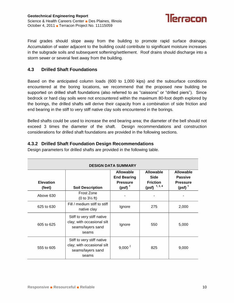
4.3.2 Drilled Shaft Foundation Design Recommendations
Design parameters for drilled shafts are provided in the following table.
DESIGN DATA SUMMARY
Elevation
(feet) Soil Description
Allowable
End Bearing
Pressure
(psf) 1
Allowable
Side
Friction
(psf) 1, 3, 4
Allowable
Passive
Pressure
(psf) 1
Above 630 Frost Zone
(0 to 3½ ft) - - -
625 to 630 Fill / medium stiff to stiff
native clay Ignore 275 2,000
605 to 625
Stiff to very stiff native
clay; with occasional silt
seams/layers sand
seams
Ignore 550 5,000
555 to 605
Stiff to very stiff native
clay; with occasional silt
seams/layers sand
seams
9,000 2 825 9,000

Geotechnical Engineering Report
Science & Health Careers Center ■ Des Plaines, Illinois October 4, 2011 ■ Terracon Project No. 11115059
Responsive ■ Resourceful ■ Reliable 11
1. The allowable end bearing capacity includes a factor of safety of 3, and the allowable side
friction and passive pressure values include a factor of safety of 2.
2. The drilled shaft should extend below elevation 605 feet to achieve this allowable end
bearing capacity.
3. For belled shafts (if used), side friction resistance should be neglected along the belled
portion of the shaft and for a distance of one bell diameter above the top of the bell.
4. Side friction values provided in the table are for compressive loads. In designing to resist
uplift loads, the allowable side friction values provided for compressive loading could be
used along with the effective weight of the drilled shaft. For belled shafts, the effective
unit weight of the soil above the bell within a cylinder defined by the bell perimeter can
also be used for uplift resistance. Buoyant concrete and soil weights should be used
below the water table. For shafts subjected to uplift loads, the drilled shaft reinforcing
steel should extend through the length were side friction is considered, and reinforcing
steel should extend into the bell if the bell uplift resistance is considered.
The following table provides estimated post-construction settlements of drilled shaft foundations
that are designed and constructed as recommended in this report. Elastic compression of the
drilled shafts should be added to these values.
DESCRIPTION VALUE
Estimated maximum total settlement ¾ inch
Estimated maximum differential settlement ½ inch
Pier caps or grade beams along the building’s perimeter areas should extend at least 3½ feet
below the lowest adjacent final grade for frost protection. Drilled shafts should be spaced at
least 3 shaft diameters apart (center-to-center) or 3 bell diameters if belled shafts are used. If
this spacing cannot be maintained, stresses from adjacent shafts could overlap in the bearing
soils, resulting in larger settlements.
Individual shafts could be designed to resist lateral loads using the allowable passive soil
pressures provided in the above table. The allowable passive pressures would apply to the
projected diameter of the shaft and require some movement to mobilize resistance. Lateral
resistance within the frost depth (3½ feet below final grade) should be ignored. Group action for
lateral resistance of drilled shafts should be taken into account when center to center spacing is
less than 8 diameters in the direction of loading. Design parameters for allowable passive
resistance in the direction of the load should be reduced in accordance with the following table.

Geotechnical Engineering Report
Science & Health Careers Center ■ Des Plaines, Illinois October 4, 2011 ■ Terracon Project No. 11115059
Responsive ■ Resourceful ■ Reliable 12
Passive Resistance Reduction Factors
Shaft Spacing
(Shaft Diameters) Reduction Factor
8D 1.0
6D 0.7
4D 0.4
3D 0.25
Lateral loads perpendicular to a row of shafts with center to center spacing of 3 diameters or
less would cause the foundations to react essentially as a vertical wall. For this case, an
allowable passive pressure equivalent to that exerted by fluids weighing 150 and 70 pcf above
and below groundwater, respectively, should be used for the projected shaft diameters. With
spacing of greater than 3 diameters, the values provided above for individual shafts may be
used.
As an alternative to using the allowable passive pressure parameters, lateral loading on the
drilled shafts could be analyzed using the LPILE computer program. LPILE analyzes shaft
deflection as a function of the design loads, shaft design and construction, and subsurface
conditions. Soil parameters for LPILE analysis of the drilled shafts are provided in the following
table.
LPILE Soil Parameters
Elevation
(feet)
LPILE
Material
Type 1
Layer
Description
Effective
Unit
Weight 2
(pcf)
Internal
Angle of
Friction
(degrees)
Undrained
Shear
Strength
(psf)
Static Soil
Modulus
Parameter,
k (pci) 5
Strain5
ε50
Above
630 3 Frost Depth 120 - - - -
625 to 630 2 Clay 60 - 1,000 100 0.01
605 to 625 2 Clay 65 - 2,000 500 0.005
555 to 605 2 Clay 70 - 3,000 1,000 0.005
1. LPILE material types: 2 = stiff clay with free water, 3 = stiff clay without free water
2. Maximum water level assumed at elevation 630 feet.
4.3.2 Drilled Shaft Foundation Construction Considerations
Drilled shafts for this project should have a minimum diameter of 30 inches. The bottom of each
drilled shaft excavation should be cleaned of loose material before placing reinforcing steel and
concrete. If water is present in a drilled shaft excavation and cannot be removed by
conventional means (such as pumping), concrete should be placed using a tremie or concrete
pump. Concrete should be placed as soon as possible after the foundation excavation is

Geotechnical Engineering Report
Science & Health Careers Center ■ Des Plaines, Illinois October 4, 2011 ■ Terracon Project No. 11115059
Responsive ■ Resourceful ■ Reliable 13
completed. Closely spaced shafts should have a staggered construction schedule that allows
for the concrete to set before an adjacent shaft is drilled.
Water was observed shallower than the expected drilled shaft depths at several of the boring
locations; therefore, the contractor should expect that temporary casing will be required for
excavation and construction of the drilled shafts. Temporary casing must also be used if
personnel need to enter the shafts to clean and/or observe the bearing surface.
Care should be taken when removing temporary casing during concrete placement. During
casing removal, the concrete level should be maintained a sufficient distance above the bottom
of the casing to counteract hydrostatic and earth pressure on the annular spacing outside of the
casing. Placement of loose soil backfill around the casing should not be permitted around the
casing prior to removal of the casing. Drilled shaft concrete should be designed with a slump of
approximately 5 to 7 inches to help facilitate removal of temporary casing and reduce the
possibility of concrete arching. Water that accumulates in drilled shaft excavations should be
removed prior to concrete placement, or a tremie method should be used for placement of the
concrete.
4.4 Floor Slab
The following recommendations for grade supported floor slabs would apply to the west part of the
building. We understand the east part of the building will have a structural slab that will be
supported on the building’s foundation system.
4.4.1 Floor Slab Design Recommendations
ITEM DESCRIPTION
Floor slab support
Native soils, tested and evaluated existing fill, or
new engineered fill materials that have been
prepared in accordance with section 4.2 and
tested/approved by the geotechnical engineer
Granular leveling course 2 6 inches of well-graded granular material
Modulus of subgrade reaction
100 pci for a soil subgrade prepared as
recommended in this report
Note: a value of 150 pci can be used at the top of
the compacted granular leveling course
1. Floor slabs should be structurally independent of building footings and walls supported on the
footings to reduce the potential for floor slab cracking caused by differential movements between
the slab and foundation.
2. The floor slab should be placed on a leveling course comprised of well-graded granular material
(e.g., IDOT CA-6 aggregate) compacted to at least 95% of the material’s modified Proctor
maximum dry density (ASTM D 1557)

Geotechnical Engineering Report
Science & Health Careers Center ■ Des Plaines, Illinois October 4, 2011 ■ Terracon Project No. 11115059
Responsive ■ Resourceful ■ Reliable 14
Joints should be constructed at regular intervals as recommended by the American Concrete
Institute (ACI) to help control the location of cracking. It should be understood that differential
settlement between the floor slabs and foundations could occur.
If moisture vapor transmission through the concrete slab is a concern, a vapor barrier should be
used. The need for, and placement of, the vapor barrier should be determined by the architect
or slab designer based on the proposed floor covering treatment, building function, concrete
properties, placement techniques, and construction schedule. For further guidance concerning
the use of a vapor barrier system, refer to Sections 302 and 360 of the American Concrete
Institute (ACI) Manual of Concrete Practice.
4.4.2 Floor Slab Construction Considerations
On most project sites, the site grading is generally accomplished early in the construction phase.
However, as construction proceeds, the subgrade may be disturbed by utility excavations,
construction traffic, desiccation, rainfall, etc. As a result, corrective action may be required prior to
placement of the granular leveling course and concrete.
The condition of the floor slab subgrades immediately prior to placement of the granular leveling
course and construction of the slabs. Particular attention should be paid to high traffic areas that
were rutted and disturbed earlier and to areas where backfilled trenches are located. Areas
where unsuitable conditions are located should be repaired by scarification/compaction or by
removing the affected material and replacing it with engineered fill.
4.5 Below Grade Walls
4.5.1 Lateral Earth Pressures
Walls with unbalanced backfill levels (e.g., below grade building walls and/or cast-in-place
concrete cantilever retaining walls) should be designed for earth pressures at least equal to
those indicated in the following table. Earth pressures will be influenced by structural design of
the walls, conditions of wall restraint, methods of construction and/or compaction and the
strength of the materials being restrained. The “active” condition assumes some wall movement
and is commonly used for free-standing concrete cantilever retaining walls. The "at-rest"
condition assumes no wall movement and is used for design of building walls, dock walls, and
other walls that are fixed and cannot rotate. The recommended design lateral earth pressures
do not include a factor of safety and do not provide for possible hydrostatic pressure on the
walls.

Geotechnical Engineering Report
Science & Health Careers Center ■ Des Plaines, Illinois October 4, 2011 ■ Terracon Project No. 11115059
Responsive ■ Resourceful ■ Reliable 15
Lateral Earth Pressure Parameters
Pressure
Conditions
Coefficient For
Backfill Type
Equivalent Fluid
Unit Weight (pcf)
Surcharge
Pressure, P1
(psf)
Earth
Pressure,
P2 (psf)
Active (Ka) Granular - 0.33
Cohesive - 0.42
40
50
(0.33)S
(0.42)S
(40)H
(50)H
At-Rest (Ko) Granular - 0.5
Cohesive - 0.58
60
70
(0.5)S
(0.58)S
(60)H
(70)H
Passive (Kp) Granular – 3.0
Cohesive – 2.4
360
290
---
---
---
---
Conditions applicable to the above recommendations include:
For active earth pressure, wall must rotate about base, with top lateral movements of about
0.002 H to 0.004 H, where H is wall height
For passive earth pressure to develop, wall must move horizontally to mobilize resistance.
Uniform surcharge, where S is surcharge pressure
In-situ soil backfill weight a maximum of 120 pcf
Horizontal backfill and surface in front of the wall, compacted to between 95 and 100
percent of standard Proctor maximum dry density
No loading from compaction equipment or other construction equipment
No loading from nearby foundations
No dynamic loading
Ignore passive pressure in frost zone
Backfill placed against structures should consist of granular or cohesive engineered fill. For
the granular values to be valid, the granular fill must extend out from the base of the wall at an

Geotechnical Engineering Report
Science & Health Careers Center ■ Des Plaines, Illinois October 4, 2011 ■ Terracon Project No. 11115059
Responsive ■ Resourceful ■ Reliable 16
angle of at least 45 degrees from vertical for the active and at-rest cases and at an angle of at
least 60 degrees from vertical for the passive case. To calculate the resistance to sliding, a
value of 0.4 should be used as the ultimate coefficient of friction between the concrete and the
underlying clay soil.
4.5.2 Subsurface Drainage
Drains should be constructed at the base of below grade walls/retaining walls to reduce the risk
of hydrostatic loading. The drain pipe should be located with its invert at the bottom of the wall
and should be surrounded with free-draining granular material graded to prevent the intrusion of
fines. A minimum 2-foot wide layer of free-draining granular material should be placed adjacent
to the wall. For exterior locations, the granular material should extend from the drainage pipes
to within about 2 feet of final grade and be capped with a cohesive fill material that is placed and
compacted as recommended in Section 4.2 of this report. At interior locations, the granular
material should extend up to the floor slab subgrade elevation. As an alternative to filter graded
gravel, free-draining 1-inch nominal size gravel could be used for the drains if the entire system,
including the gravel, is encapsulated with an appropriate geotextile filter fabric.
The drainage networks (pipes) for subdrains should be sloped to provide positive gravity
drainage to sumps equipped for automated pumping or to a down gradient storm sewer or other
suitable outlet that will allow gravity drainage. Redundant pumps with battery backup power
could be considered to reduce the risk of hydrostatic pressure and seepage in the event of
pump and/or power failure. Periodic maintenance of drainage systems is necessary so that they
do not become plugged and inoperative.
A prefabricated drainage structure placed against below grade walls may also be used as an
alternative to free-draining granular fill above the pipe. A prefabricated drainage structure
consists of a plastic drainage core or mesh that is covered with filter fabric to prevent soil
intrusion. The drainage structure is fastened to the wall after the wall has been waterproofed.
4.6 Pavements
4.6.1 Pavement Design Recommendations
Pavement thickness design is dependent upon:
the anticipated traffic conditions,
subgrade and paving material characteristics, and
climate conditions at the project site.
Specific information regarding anticipated vehicle types, axle loads and traffic volumes was not
provided. In developing our recommendations, we have considered that traffic will consist
primarily of automobile traffic and a limited number of delivery trucks and trash collection trucks.
The “Parking Areas” pavement section is for automobile traffic only. The “Drives” pavement
section considers automobile traffic and a maximum of five delivery trucks/trash collection trucks

Geotechnical Engineering Report
Science & Health Careers Center ■ Des Plaines, Illinois October 4, 2011 ■ Terracon Project No. 11115059
Responsive ■ Resourceful ■ Reliable 17
per day. If heavier vehicle types or higher traffic volumes are expected, Terracon should be
notified and these recommendations should be reviewed.
Recommended minimum pavement sections for parking areas and drives are provided in the
following table.
Pavement Area Minimum Pavement Section
Parking Areas 3” ACC
8” Crushed Stone Aggregate 2
Drives 4” ACC
10” Crushed Stone Aggregate 2
Trash Container Pad 1
7” PCC
4” Crushed Stone Aggregate
1. Portland cement concrete pavements are recommended for areas subject to repeated truck traffic, truck turning areas, and trash container pads. The trash container pad should be large enough to support the container and the tipping axle of the trash collection vehicle.
2. IDOT CA-6 or an approved alternate gradation.
Pavements and subgrades will be subject to freeze-thaw cycles and seasonal fluctuations in
moisture content. The pavement sections provided in the table above were developed based
on local soil and climate conditions. Asphalt, concrete and aggregate base course materials for
pavements should conform to the applicable Illinois DOT "Standard Specifications of Road and
Bridge Construction.” Concrete pavement should be air-entrained and have a minimum
compressive strength of 4,000 psi after 28 days of laboratory curing (ASTM C 31).
Construction traffic on the pavements was not considered in developing the estimated minimum
pavement thicknesses. If the pavements will be subject to construction equipment/vehicles, the
pavement sections should be revised to consider the additional loading.
The pavement sections provided above assume that the subgrade soils will not experience
significant increases in moisture content. Paved areas should be sloped to provide rapid drainage
of surface water and to drain water away from the pavement edges. Water should not be allowed
to accumulate on or adjacent to the pavement, since this could saturate and soften the subgrade
soils and subsequently accelerate pavement deterioration. Periodic maintenance of the
pavements will be required. Cracks should be sealed, and areas exhibiting distress should be
repaired promptly to help prevent further deterioration. Even with periodic maintenance, some
movement and related cracking may still occur and repairs may be required.

Geotechnical Engineering Report
Science & Health Careers Center ■ Des Plaines, Illinois October 4, 2011 ■ Terracon Project No. 11115059
Responsive ■ Resourceful ■ Reliable 18
4.6.2 Pavement Construction Considerations
Pavement subgrades should be prepared in accordance with the recommendations presented
in Sections 4.1 and 4.2 of this report. Grading and paving is commonly performed by separate
contractors and there is often a time lapse between the end of grading operations and the
commencement of paving. Subgrades prepared early in the construction process may become
disturbed by construction traffic. Non-uniform subgrades often result in poor pavement
performance and local failures relatively soon after pavements are constructed. Depending on
the paving equipment used by the contractor, measures may be required to improve subgrade
strength to greater depths for support of heavily loaded concrete/asphalt trucks.
Before paving, pavement subgrades should be proofrolled with a loaded tandem-axle dump
truck (minimum gross weight of 25 tons) or other approved rubber-tired equipment providing an
equivalent subgrade loading. Proofrolling of the subgrade should help locate soft, yielding, or
otherwise unsuitable soil at or just below the exposed subgrade level. Unsuitable areas
observed at this time should be improved by scarification and compaction or be removed and
replaced with engineered fill.
4.7 Seismic Site Class
Code Site Class
2009 International Building Code (IBC)1 D
1. In general accordance with Table 1613.5.2 of the IBC.
2. The 2009 IBC requires a site soil profile determination extending a depth of 100 feet. The
geophysical testing extended to a depth of 100 feet. The maximum depth explored in the borings
was approximately 80 feet, with the borings terminating in stiff to very stiff clay soils. The site class
was evaluated using the shear wave velocities estimated from the geophysical testing and
conditions encountered in the borings.
Please refer to Appendix A, Exhibit A-1 for a description of the geophysical testing used to
evaluate the IBC seismic site class. The geophysical test results are presented in Appendix A,
Exhibits A-20 and A-21.
5.0 GENERAL COMMENTS
Terracon should be retained to review the final design plans and specifications so comments
can be made regarding interpretation and implementation of our geotechnical recommendations
in the design and specifications. Terracon also should be retained to provide observation and
testing services during grading, excavation, foundation construction and other earth-related
construction phases of the project.

Geotechnical Engineering Report
Science & Health Careers Center ■ Des Plaines, Illinois October 4, 2011 ■ Terracon Project No. 11115059
Responsive ■ Resourceful ■ Reliable 19
Support of slabs and pavements on/above existing undocumented fill is discussed in this report.
Even with the construction observation/testing recommended in this report, a risk remains for
the owner that unsuitable materials within or buried by the fill will not be discovered. This may
result in larger than normal settlement and damage to slabs and pavements supported above
existing fill, requiring additional maintenance. This risk cannot be eliminated without removing
the existing fill from below the building and pavement areas, but can be reduced by thorough
observation and testing as discussed herein.
The analysis and recommendations presented in this report are based upon the data obtained
from the borings performed at the indicated locations and from other information discussed in
this report. This report does not reflect variations that may occur between borings, across the
site, or due to the modifying effects of construction or weather. The nature and extent of such
variations may not become evident until during or after construction. If variations appear, we
should be immediately notified so that further evaluation and supplemental recommendations
can be provided.
The scope of geotechnical services for this project does not include either specifically or by
implication any environmental or biological (e.g., mold, fungi, bacteria) assessment of the site or
identification or prevention of pollutants, hazardous materials or conditions. If the owner is
concerned about the potential for such contamination or pollution, other studies should be
undertaken.
This report has been prepared for the exclusive use of our client for specific application to the
project discussed and has been prepared in accordance with generally accepted geotechnical
engineering practices. Site safety, excavation support, and dewatering requirements are the
responsibility of others. In the event that changes in the nature, design, or location of the project
as outlined in this report are planned, the conclusions and recommendations contained in this
report shall not be considered valid unless Terracon reviews the changes and either verifies or
modifies the conclusions of this report in writing.

APPENDIX A
FIELD EXPLORATION

Geotechnical Engineering Report
Science & Health Careers Center ■ Des Plaines, Illinois October 4, 2011 ■ Terracon Project No. 11115059
Responsive ■ Resourceful ■ Reliable Exhibit A-1
Field Exploration Description
The borings were drilled at the approximate locations indicated on the attached Boring Location
Plan (Exhibit A-2). Terracon personnel laid out the boring locations in the field by determining
distances from available reference features with a measuring wheel and estimating right angles.
Surface elevations at the boring locations (rounded to the nearest foot) were interpolated from
the site topographic plan prepared by Manhard Consulting. Differences could occur from
interpolation and from superimposing approximate boring locations on the topographic plan.
The locations and elevations of the borings should be considered accurate only to the degree
implied by the means and methods used to define them.
The borings were drilled with truck-mounted and ATV-mounted, rotary drill rigs using continuous
flight, hollow-stemmed augers to advance the boreholes. Soil samples were obtained using both
thin-walled tube and split-barrel sampling procedures. In the thin-walled tube sampling
procedure, a thin-walled, seamless steel tube with a sharp cutting edge is pushed hydraulically into
the ground to obtain samples of cohesive or moderately cohesive soils. In the split barrel
sampling procedure, a standard 2-inch (outside diameter) split-barrel sampling spoon is driven
into the ground with a 140-pound automatic hammer falling a distance of 30 inches. The
number of blows required to advance the sampling spoon the last 12 inches (or less) of a
normal 18-inch penetration is recorded as the Standard Penetration Test (SPT) resistance
value. These values, also referred to as SPT N-values, are used to estimate the relative density
of granular soils and the consistency of cohesive soils. The SPT N-values are provided on the
boring logs at the depths of occurrence. The samples were sealed and transported to the
laboratory for testing and classification. Upon completion of drilling, the boreholes were
backfilled with auger cuttings and pavements were surface patched.
The drill crew prepared a field log of each boring. These logs included visual classifications of the
materials encountered during drilling and the driller’s interpretation of the subsurface conditions
between samples. The boring logs included with this report represent the engineer's interpretation
of the field logs and include modifications based on laboratory observation and tests of the
samples.
Geophysical (ReMi) Testing Description
Terracon used a seismic refraction system consisting of a seismograph and using a linear array
of 12 geophones to perform a site-specific seismic class survey. Two tests were performed in
mutually perpendicular directions (approximately north-south and east-west lines) near the
proposed building addition. Refraction microtremors (ReMi) produced by ambient seismic noise
were recorded. These data were processed to derive a shear wave profile and an average
shear-wave velocity along the array for a corresponding depth of about 100 feet. The test
results are presented in this appendix as Exhibits A-22 and A-23.


3000*
4000*
4500*
3000*
3000*
4000*
4000*
5000*
CL
CL
CLML
CL
CL
CL
CL
CL
CL
1
2
3
4
5
6
7
8
9
10
18
18
18
18
18
18
18
18
18
18
11
9
11
19
15
8
10
12
14
15
HSSS
HSSS
HSSS
HSSS
HS
SS
HS
SS
HS
SS
HS
SS
HS
SS
HS
SS
HS
12
19
18
14
22
16
12
17
10
16
0.31.2
3.5
6
631.5631
628.5
626
Approx. 4" AsphaltApprox. 10" Crushed Stone AggregateFILL: LEAN CLAY, TRACE SAND ANDGRAVEL, gray, trace brownLEAN CLAY, TRACE SAND, brown andgray, stiffLEAN CLAY, TRACE SAND ANDGRAVEL, brown, stiff to very stiff
turning gray
Sample 4: with silt seams
Sample 9: with sand
UN
CO
NF
INE
DS
TR
EN
GT
H,
psf
TESTS
DESCRIPTION
Approx. Surface Elev.: 632 ft
BO
RE
2 1
1115
059.
GP
J P
RO
FIL
E.G
DT
10
/3/1
1
DE
PT
H,
ft.
TY
PE
NU
MB
ER
DR
Y U
NIT
WT
pcf
RE
CO
VE
RY
, in
.
5
10
15
20
25
30
35
40
SP
T -
N *
*B
LOW
S /
ft.
SAMPLES
US
CS
SY
MB
OL
WA
TE
RC
ON
TE
NT
, %
9-8-11NONE WD AB
11115059
GR
AP
HIC
LO
G
Continued Next Page
1600 E. Golf Road PROJECT
9-8-11
Legat Architects
*Pocket Penetrometer**140 Lbs Automatic SPT Hammer
Des Plaines, Illinois Science & Health Careers Center
The stratification lines represent the approximate boundary lines
SITE
BORING STARTED
GTCRIG
between soil and rock types: in-situ, the transition may be gradual.
Page 1 of 2
BORING COMPLETED
APPROVED KCB
WATER LEVEL OBSERVATIONS, ft
TDHFOREMAN
Oakton Community CollegeCLIENT
JOB #
61
ARCHITECT
LOG OF BORING NO. 1
WL
WL
EXHIBIT A-3

5000*
4000*
4000*
6000*
3000*
4000*
CL
CL
CL
CLSC
CLSC
CL
CL
CL
11
12
13
14
15
16
17
18
18
18
18
18
18
18
18
18
15
12
12
11
10
19
11
12
SS
HS
SS
HS
SS
HS
SS
HS
SS
HS
SS
HS
SS
HS
SS
13
17
17
18
14
12
16
1480 552
LEAN CLAY, TRACE SAND ANDGRAVEL, gray, stiff to very stiff
Samples 14 and 15: with sand seams
BOTTOM OF BORING
UN
CO
NF
INE
DS
TR
EN
GT
H,
psf
TESTS
DESCRIPTION
BO
RE
2 1
1115
059.
GP
J P
RO
FIL
E.G
DT
10
/3/1
1
DE
PT
H,
ft.
TY
PE
NU
MB
ER
DR
Y U
NIT
WT
pcf
RE
CO
VE
RY
, in
.
45
50
55
60
65
70
75
80
SP
T -
N *
*B
LOW
S /
ft.
SAMPLES
US
CS
SY
MB
OL
WA
TE
RC
ON
TE
NT
, %
9-8-11NONE WD AB
11115059
GR
AP
HIC
LO
G
1600 E. Golf Road PROJECT
9-8-11
Legat Architects
*Pocket Penetrometer**140 Lbs Automatic SPT Hammer
Des Plaines, Illinois Science & Health Careers Center
The stratification lines represent the approximate boundary lines
SITE
BORING STARTED
GTCRIG
between soil and rock types: in-situ, the transition may be gradual.
Page 2 of 2
BORING COMPLETED
APPROVED KCB
WATER LEVEL OBSERVATIONS, ft
TDHFOREMAN
Oakton Community CollegeCLIENT
JOB #
61
ARCHITECT
LOG OF BORING NO. 1
WL
WL
EXHIBIT A-3

3000*
2500*
5000*
5000*
4000*
4500*
5000*
4000*
CL
CL
CL
CL
CL
CL
CL
ML
CL
1
2
3
4
5
6
7
8
9
10
18
18
15
18
18
18
18
18
13
18
7
9
8
17
16
13
15
16
18
10
HSSS
HSSS
HSSS
HSSS
HS
SS
HS
SS
HS
SS
HS
SS
HS
SS
HS
SS
22
23
20
18
18
16
17
15
15
14
LL = 37PL = 19PI = 18
0.30.92.5
8
33.5
35
40
632.5632
630.5
625
599.5
598
593
Approx. 3" AsphaltApprox. 8" Crushed Stone AggregateFILL: LEAN CLAY, TRACE SAND ANDGRAVEL, brown and grayLEAN CLAY, TRACE SAND, brown andgray, stiff
LEAN CLAY, TRACE SAND ANDGRAVEL, brown, stiff to very stiff
turning gray
CLAYEY SILT, TRACE SAND, gray,medium denseLEAN CLAY, TRACE SAND ANDGRAVEL, gray, stiff
BOTTOM OF BORING
UN
CO
NF
INE
DS
TR
EN
GT
H,
psf
TESTS
DESCRIPTION
Approx. Surface Elev.: 633 ft
BO
RE
2 1
1115
059.
GP
J P
RO
FIL
E.G
DT
10
/3/1
1
DE
PT
H,
ft.
TY
PE
NU
MB
ER
DR
Y U
NIT
WT
pcf
RE
CO
VE
RY
, in
.
5
10
15
20
25
30
35
40
SP
T -
N *
*B
LOW
S /
ft.
SAMPLES
US
CS
SY
MB
OL
WA
TE
RC
ON
TE
NT
, %
9-10-11NONE WD AB
11115059
GR
AP
HIC
LO
G
1600 E. Golf Road PROJECT
9-10-11
Legat Architects
*Pocket Penetrometer**140 Lbs Automatic SPT Hammer
Des Plaines, Illinois Science & Health Careers Center
The stratification lines represent the approximate boundary lines
SITE
BORING STARTED
GTCRIG
between soil and rock types: in-situ, the transition may be gradual.
Page 1 of 1
BORING COMPLETED
APPROVED KCB
WATER LEVEL OBSERVATIONS, ft
TDHFOREMAN
Oakton Community College
AT
TE
RB
ER
GLI
MIT
S
CLIENT
JOB #
NONE
ARCHITECT
LOG OF BORING NO. 2
WL
WL
EXHIBIT A-4

3000*
4000*
4000*
3000*
5000*
4500*
5000*
CL
CL
CL
CL
CL
CL
CL-MLML
CL
1
2
3
4
5
6
7
8
9
10
15
16
16
18
18
18
18
18
7
16
7
8
9
13
13
9
16
14
15
14
HSSS
HSSS
HSSS
HSSS
HS
SS
HS
SS
HS
SS
HS
SS
HS
SS
HS
SS
19
21
16
16
19
14
16
19
16
18
0.30.9
6
33
36
40
632.5632
627
600
597
593
Approx. 3" AsphaltApprox. 8" Crushed Stone AggregateFILL: LEAN CLAY, TRACE SAND ANDGRAVEL, dark brown, brown and graySample 2: trace organics
LEAN CLAY, TRACE SAND ANDGRAVEL, brown, stiff to very stiff
turning gray
SILTY CLAY, TRACE SAND, gray, stiff tovery stiffSample 9: with silt seamsLEAN CLAY, TRACE SAND ANDGRAVEL, gray, very stiff
BOTTOM OF BORING
UN
CO
NF
INE
DS
TR
EN
GT
H,
psf
TESTS
DESCRIPTION
Approx. Surface Elev.: 633 ft
BO
RE
2 1
1115
059.
GP
J P
RO
FIL
E.G
DT
10
/3/1
1
DE
PT
H,
ft.
TY
PE
NU
MB
ER
DR
Y U
NIT
WT
pcf
RE
CO
VE
RY
, in
.
5
10
15
20
25
30
35
40
SP
T -
N *
*B
LOW
S /
ft.
SAMPLES
US
CS
SY
MB
OL
WA
TE
RC
ON
TE
NT
, %
9-10-11NONE WD AB
11115059
GR
AP
HIC
LO
G
1600 E. Golf Road PROJECT
9-10-11
Legat Architects
*Pocket Penetrometer**140 Lbs Automatic SPT Hammer
Des Plaines, Illinois Science & Health Careers Center
The stratification lines represent the approximate boundary lines
SITE
BORING STARTED
GTCRIG
between soil and rock types: in-situ, the transition may be gradual.
Page 1 of 1
BORING COMPLETED
APPROVED KCB
WATER LEVEL OBSERVATIONS, ft
TDHFOREMAN
Oakton Community CollegeCLIENT
JOB #
NONE
ARCHITECT
LOG OF BORING NO. 3
WL
WL
EXHIBIT A-5

3000*
4000*
4000*
3000*
3000*
4000*
4000*
4000*
CL
CL
CL-MLML
CL
CL
CL
CL
CL
CL
1
2
3
4
5
6
7
8
9
10
18
18
18
18
18
18
18
18
18
18
17
10
10
15
13
9
9
11
13
13
HSSS
HSSS
HSSS
HSSS
HS
SS
HS
SS
HS
SS
HS
SS
HS
SS
HS
SS
15
19
16
17
18
14
18
19
14
15
0.31.3
4
8.5
13
40
632.5631.5
629
624.5
620
593
Approx. 3" AsphaltApprox. 12" Crushed Stone AggregateFILL: SANDY LEAN CLAY, TRACEGRAVEL, brown, trace grayLEAN CLAY, TRACE SAND ANDGRAVEL, brown and gray, stiff
SILTY CLAY, TRACE SAND, brown,trace gray, stiffSample 4: with silt seams
LEAN CLAY, TRACE SAND ANDGRAVEL, gray, stiff to very stiff
BOTTOM OF BORING
UN
CO
NF
INE
DS
TR
EN
GT
H,
psf
TESTS
DESCRIPTION
Approx. Surface Elev.: 633 ft
BO
RE
2 1
1115
059.
GP
J P
RO
FIL
E.G
DT
10
/3/1
1
DE
PT
H,
ft.
TY
PE
NU
MB
ER
DR
Y U
NIT
WT
pcf
RE
CO
VE
RY
, in
.
5
10
15
20
25
30
35
40
SP
T -
N *
*B
LOW
S /
ft.
SAMPLES
US
CS
SY
MB
OL
WA
TE
RC
ON
TE
NT
, %
9-2-11NONE WD AB
11115059
GR
AP
HIC
LO
G
1600 E. Golf Road PROJECT
9-2-11
Legat Architects
*Pocket Penetrometer**140 Lbs Automatic SPT Hammer
Des Plaines, Illinois Science & Health Careers Center
The stratification lines represent the approximate boundary lines
SITE
BORING STARTED
GTCRIG
between soil and rock types: in-situ, the transition may be gradual.
Page 1 of 1
BORING COMPLETED
APPROVED KCB
WATER LEVEL OBSERVATIONS, ft
TDHFOREMAN
Oakton Community CollegeCLIENT
JOB #
NONE
ARCHITECT
LOG OF BORING NO. 4
WL
WL
EXHIBIT A-6

3000*
3500*
6000*
3000*
4500*
4000*
6000*
CL
CL
CL
ML
CL
CL
CL
ML
CL
1
2
3
4
5
6
7
8
9
10
16
18
18
18
18
18
18
18
18
18
7
8
10
19
15
8
14
11
34
17
HSSS
HSSS
HSSS
HSSS
HS
SS
HS
SS
HS
SS
HS
SS
HS
SS
HS
SS
14
21
18
17
19
13
19
16
16
17
0.30.9
3
13.5
18.5
32
37
40
632.5632
630
619.5
614.5
601
596
593
Approx. 3" AsphaltApprox. 9" Crushed Stone AggregateFILL: LEAN CLAY, TRACE SAND ANDGRAVEL, brown and grayLEAN CLAY, TRACE SAND ANDGRAVEL, brown and gray, stiff to verystiff
CLAYEY SILT, TRACE SAND, gray,medium dense
LEAN CLAY, TRACE SAND, TRACEGRAVEL, gray, stiff to very stiff
Sample 6: with sand
CLAYEY SILT, TRACE SAND, gray,dense
LEAN CLAY, TRACE SAND ANDGRAVEL, gray, very stiff
BOTTOM OF BORING
UN
CO
NF
INE
DS
TR
EN
GT
H,
psf
TESTS
DESCRIPTION
Approx. Surface Elev.: 633 ft
BO
RE
2 1
1115
059.
GP
J P
RO
FIL
E.G
DT
10
/3/1
1
DE
PT
H,
ft.
TY
PE
NU
MB
ER
DR
Y U
NIT
WT
pcf
RE
CO
VE
RY
, in
.
5
10
15
20
25
30
35
40
SP
T -
N *
*B
LOW
S /
ft.
SAMPLES
US
CS
SY
MB
OL
WA
TE
RC
ON
TE
NT
, %
9-10-1113.5 WD AB
11115059
GR
AP
HIC
LO
G
1600 E. Golf Road PROJECT
9-10-11
Legat Architects
*Pocket Penetrometer**140 Lbs Automatic SPT Hammer
Des Plaines, Illinois Science & Health Careers Center
The stratification lines represent the approximate boundary lines
SITE
BORING STARTED
GTCRIG
between soil and rock types: in-situ, the transition may be gradual.
Page 1 of 1
BORING COMPLETED
APPROVED KCB
WATER LEVEL OBSERVATIONS, ft
TDHFOREMAN
Oakton Community CollegeCLIENT
JOB #
NONE
ARCHITECT
LOG OF BORING NO. 5
WL
WL
EXHIBIT A-7
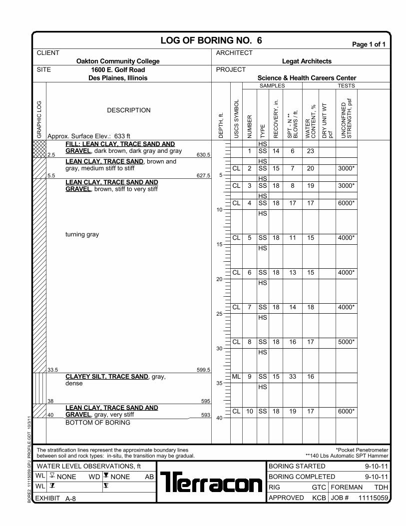
3000*
3000*
6000*
4000*
4000*
4000*
5000*
6000*
CL
CL
CL
CL
CL
CL
CL
ML
CL
1
2
3
4
5
6
7
8
9
10
14
15
18
18
18
18
18
18
15
18
6
7
8
17
11
13
14
16
33
19
HSSS
HSSS
HSSS
HSSS
HS
SS
HS
SS
HS
SS
HS
SS
HS
SS
HS
SS
23
20
19
17
15
15
18
17
16
17
2.5
5.5
33.5
38
40
630.5
627.5
599.5
595
593
FILL: LEAN CLAY, TRACE SAND ANDGRAVEL, dark brown, dark gray and gray
LEAN CLAY, TRACE SAND, brown andgray, medium stiff to stiff
LEAN CLAY, TRACE SAND ANDGRAVEL, brown, stiff to very stiff
turning gray
CLAYEY SILT, TRACE SAND, gray,dense
LEAN CLAY, TRACE SAND ANDGRAVEL, gray, very stiffBOTTOM OF BORING
UN
CO
NF
INE
DS
TR
EN
GT
H,
psf
TESTS
DESCRIPTION
Approx. Surface Elev.: 633 ft
BO
RE
2 1
1115
059.
GP
J P
RO
FIL
E.G
DT
10
/3/1
1
DE
PT
H,
ft.
TY
PE
NU
MB
ER
DR
Y U
NIT
WT
pcf
RE
CO
VE
RY
, in
.
5
10
15
20
25
30
35
40
SP
T -
N *
*B
LOW
S /
ft.
SAMPLES
US
CS
SY
MB
OL
WA
TE
RC
ON
TE
NT
, %
9-10-11NONE WD AB
11115059
GR
AP
HIC
LO
G
1600 E. Golf Road PROJECT
9-10-11
Legat Architects
*Pocket Penetrometer**140 Lbs Automatic SPT Hammer
Des Plaines, Illinois Science & Health Careers Center
The stratification lines represent the approximate boundary lines
SITE
BORING STARTED
GTCRIG
between soil and rock types: in-situ, the transition may be gradual.
Page 1 of 1
BORING COMPLETED
APPROVED KCB
WATER LEVEL OBSERVATIONS, ft
TDHFOREMAN
Oakton Community CollegeCLIENT
JOB #
NONE
ARCHITECT
LOG OF BORING NO. 6
WL
WL
EXHIBIT A-8

3000*
3000*
4000*
4000*
4000*
3000*
4000*
4000*
CL
CL
CL
CL
CL
CL
CL
ML
CL
1
2
3
4
5
6
7
8
9
10
18
18
18
18
18
18
18
18
16
18
10
9
8
12
11
11
9
12
11
10
HSSS
HSSS
HSSS
HSSS
HS
SS
HS
SS
HS
SS
HS
SS
HS
SS
HS
SS
22
21
21
17
19
15
17
19
17
20
LL = 31PL = 18PI = 13
1.1
3
33
36
40
632
630
600
597
593
Approx. 13" Topsoil FillFILL: LEAN CLAY, TRACE SAND ANDGRAVEL, brown and grayLEAN CLAY, TRACE SAND ANDGRAVEL, brown and gray, stiff to verystiff
turning gray
CLAYEY SILT, TRACE SAND, gray,medium dense
LEAN CLAY, TRACE SAND ANDGRAVEL, gray, stiff
BOTTOM OF BORING
UN
CO
NF
INE
DS
TR
EN
GT
H,
psf
TESTS
DESCRIPTION
Approx. Surface Elev.: 633 ft
BO
RE
2 1
1115
059.
GP
J P
RO
FIL
E.G
DT
10
/3/1
1
DE
PT
H,
ft.
TY
PE
NU
MB
ER
DR
Y U
NIT
WT
pcf
RE
CO
VE
RY
, in
.
5
10
15
20
25
30
35
40
SP
T -
N *
*B
LOW
S /
ft.
SAMPLES
US
CS
SY
MB
OL
WA
TE
RC
ON
TE
NT
, %
9-7-11NONE WD AB
11115059
GR
AP
HIC
LO
G
1600 E. Golf Road PROJECT
9-7-11
Legat Architects
*Pocket Penetrometer**140 Lbs Automatic SPT Hammer
Des Plaines, Illinois Science & Health Careers Center
The stratification lines represent the approximate boundary lines
SITE
BORING STARTED
GTCRIG
between soil and rock types: in-situ, the transition may be gradual.
Page 1 of 1
BORING COMPLETED
APPROVED KCB
WATER LEVEL OBSERVATIONS, ft
TDHFOREMAN
Oakton Community College
AT
TE
RB
ER
GLI
MIT
S
CLIENT
JOB #
NONE
ARCHITECT
LOG OF BORING NO. 7
WL
WL
EXHIBIT A-9

2000*
3000*
4000*
3000*
4000*
4000*
4000*
7000*
5000*
CL
CL
CL
CL
CL
CL
CL
CL-MLML
CL
1
2
3
4
5
6
7
8
9
10
15
18
18
18
8
18
18
18
18
18
4
6
8
14
8
11
12
11
23
16
HSSS
HSSS
HSSS
HSSS
HS
SS
HS
SS
HS
SS
HS
SS
HS
SS
HS
SS
HS
31
23
21
18
20
16
17
19
15
16
0.3
4
5.5
33
37
632.5
629
627.5
600
596
Approx. 4" Topsoil FillFILL: LEAN CLAY, TRACE SAND, darkbrown
Sample 1: trace organicsLEAN CLAY, TRACE SAND, brown andgray, medium stiffLEAN CLAY, TRACE SAND ANDGRAVEL, brown, stiff
turning gray
SILTY CLAY, TRACE SAND, gray, verystiffSample 9: with silt seams
LEAN CLAY, TRACE SAND ANDGRAVEL, gray, stiff to very stiff
UN
CO
NF
INE
DS
TR
EN
GT
H,
psf
TESTS
DESCRIPTION
Approx. Surface Elev.: 633 ft
BO
RE
2 1
1115
059.
GP
J P
RO
FIL
E.G
DT
10
/3/1
1
DE
PT
H,
ft.
TY
PE
NU
MB
ER
DR
Y U
NIT
WT
pcf
RE
CO
VE
RY
, in
.
5
10
15
20
25
30
35
40
SP
T -
N *
*B
LOW
S /
ft.
SAMPLES
US
CS
SY
MB
OL
WA
TE
RC
ON
TE
NT
, %
9-7-1139 WD AB
11115059
GR
AP
HIC
LO
G
Continued Next Page
1600 E. Golf Road PROJECT
9-7-11
Legat Architects
*Pocket Penetrometer**140 Lbs Automatic SPT Hammer
Des Plaines, Illinois Science & Health Careers Center
The stratification lines represent the approximate boundary lines
SITE
BORING STARTED
GTCRIG
between soil and rock types: in-situ, the transition may be gradual.
Page 1 of 2
BORING COMPLETED
APPROVED KCB
WATER LEVEL OBSERVATIONS, ft
TDHFOREMAN
Oakton Community CollegeCLIENT
JOB #
39
ARCHITECT
LOG OF BORING NO. 8
WL
WL
EXHIBIT A-10

6000*
7000*
5000*
3000*
4500*
6000*
4000*
CL
CL
CL
CLML
CLSC
CL
CL
CL
11
12
13
14
15
16
17
18
18
18
18
8
10
18
18
18
18
64
20
16
10
16
19
13
SS
HS
SS
HS
SS
HS
SS
HS
SS
HS
SS
HS
SS
HS
SS
16
11
16
15
13
15
12
1580 553
LEAN CLAY, TRACE SAND ANDGRAVEL, gray, stiff to hard
Sample 12: sampler encountered coarsegravel/cobble
Sample 14: with silt seams
Sample 15: with sand seams
BOTTOM OF BORING
UN
CO
NF
INE
DS
TR
EN
GT
H,
psf
TESTS
DESCRIPTION
BO
RE
2 1
1115
059.
GP
J P
RO
FIL
E.G
DT
10
/3/1
1
DE
PT
H,
ft.
TY
PE
NU
MB
ER
DR
Y U
NIT
WT
pcf
RE
CO
VE
RY
, in
.
45
50
55
60
65
70
75
80
SP
T -
N *
*B
LOW
S /
ft.
SAMPLES
US
CS
SY
MB
OL
WA
TE
RC
ON
TE
NT
, %
9-7-1139 WD AB
11115059
GR
AP
HIC
LO
G
1600 E. Golf Road PROJECT
9-7-11
Legat Architects
*Pocket Penetrometer**140 Lbs Automatic SPT Hammer
Des Plaines, Illinois Science & Health Careers Center
The stratification lines represent the approximate boundary lines
SITE
BORING STARTED
GTCRIG
between soil and rock types: in-situ, the transition may be gradual.
Page 2 of 2
BORING COMPLETED
APPROVED KCB
WATER LEVEL OBSERVATIONS, ft
TDHFOREMAN
Oakton Community CollegeCLIENT
JOB #
39
ARCHITECT
LOG OF BORING NO. 8
WL
WL
EXHIBIT A-10

3000*
3000*
4000*
4000*
4500*
4000*
4000*
CL
CL
CL
CL
CL
CL
ML
CL
1
2
3
4
5
6
7
8
9
10
18
3
18
13
18
18
18
18
18
18
11
7
8
8
10
9
12
11
47
12
HSSS
HSSS
HSSS
HSSS
HS
SS
HS
SS
HS
SS
HS
SS
HS
SS
HS
SS
HS
14
16
19
21
21
13
19
19
16
14
0.5
6
33
36
633.5
628
601
598
Approx. 6" Topsoil FillFILL: LEAN CLAY, TRACE SAND ANDGRAVEL, brown
LEAN CLAY, TRACE SAND ANDGRAVEL, brown and gray, stiff to verystiff
turning gray
CLAYEY SILT, TRACE SAND, gray,dense
LEAN CLAY, TRACE SAND ANDGRAVEL, gray, stiff to hard
UN
CO
NF
INE
DS
TR
EN
GT
H,
psf
TESTS
DESCRIPTION
Approx. Surface Elev.: 634 ft
BO
RE
2 1
1115
059.
GP
J P
RO
FIL
E.G
DT
10
/3/1
1
DE
PT
H,
ft.
TY
PE
NU
MB
ER
DR
Y U
NIT
WT
pcf
RE
CO
VE
RY
, in
.
5
10
15
20
25
30
35
40
SP
T -
N *
*B
LOW
S /
ft.
SAMPLES
US
CS
SY
MB
OL
WA
TE
RC
ON
TE
NT
, %
9-7-1168.5 WD AB
11115059
GR
AP
HIC
LO
G
Continued Next Page
1600 E. Golf Road PROJECT
9-7-11
Legat Architects
*Pocket Penetrometer**140 Lbs Automatic SPT Hammer
Des Plaines, Illinois Science & Health Careers Center
The stratification lines represent the approximate boundary lines
SITE
BORING STARTED
GTCRIG
between soil and rock types: in-situ, the transition may be gradual.
Page 1 of 2
BORING COMPLETED
APPROVED KCB
WATER LEVEL OBSERVATIONS, ft
TDHFOREMAN
Oakton Community CollegeCLIENT
JOB #
30
ARCHITECT
LOG OF BORING NO. 9
WL
WL
EXHIBIT A-11

6000*
4000*
5000*
4000*
4500*
9000+*
4000*
CL
CLML
CL
CL
CL
CL
CL
CL
11
12
13
14
15
16
17
18
18
18
18
18
18
18
18
18
19
34
10
12
13
12
40
13
SS
HS
SS
HS
SS
HS
SS
HS
SS
HS
SS
HS
SS
HS
SS
16
15
20
14
12
18
11
1380 554
LEAN CLAY, TRACE SAND ANDGRAVEL, gray, stiff to hard
Sample 12: with silt seams
BOTTOM OF BORING
UN
CO
NF
INE
DS
TR
EN
GT
H,
psf
TESTS
DESCRIPTION
BO
RE
2 1
1115
059.
GP
J P
RO
FIL
E.G
DT
10
/3/1
1
DE
PT
H,
ft.
TY
PE
NU
MB
ER
DR
Y U
NIT
WT
pcf
RE
CO
VE
RY
, in
.
45
50
55
60
65
70
75
80
SP
T -
N *
*B
LOW
S /
ft.
SAMPLES
US
CS
SY
MB
OL
WA
TE
RC
ON
TE
NT
, %
9-7-1168.5 WD AB
11115059
GR
AP
HIC
LO
G
1600 E. Golf Road PROJECT
9-7-11
Legat Architects
*Pocket Penetrometer**140 Lbs Automatic SPT Hammer
Des Plaines, Illinois Science & Health Careers Center
The stratification lines represent the approximate boundary lines
SITE
BORING STARTED
GTCRIG
between soil and rock types: in-situ, the transition may be gradual.
Page 2 of 2
BORING COMPLETED
APPROVED KCB
WATER LEVEL OBSERVATIONS, ft
TDHFOREMAN
Oakton Community CollegeCLIENT
JOB #
30
ARCHITECT
LOG OF BORING NO. 9
WL
WL
EXHIBIT A-11

3000*
2000*
3000*
7000*
4000*
4000*
4000*
4000*
CL
CL
CL
CL
ML
CL
CL
CL
ML
CL
1
2
3
4
5
6
7
8
9
10
15
18
18
16
18
18
18
18
18
18
7
6
9
22
17
9
9
10
27
10
HSSS
HSSS
HSSS
HSSS
HS
SS
HS
SS
HS
SS
HS
SS
HS
SS
HS
SS
22
20
20
17
21
22
18
18
16
17
1.5
3
11.5
18
33
36
40
631.5
630
621.5
615
600
597
593
Approx. 18" Topsoil
LEAN CLAY, TRACE SAND ANDORGANICS, dark brown, stiffLEAN CLAY, TRACE SAND ANDGRAVEL, brown, medium stiff to very stiff
grayish brown
CLAYEY SILT, TRACE SAND, gray,medium dense
LEAN CLAY, TRACE SAND ANDGRAVEL, gray, stiff
CLAYEY SILT, TRACE SAND, gray,medium dense
LEAN CLAY, TRACE SAND ANDGRAVEL, gray, stiff
BOTTOM OF BORING
UN
CO
NF
INE
DS
TR
EN
GT
H,
psf
TESTS
DESCRIPTION
Approx. Surface Elev.: 633 ft
BO
RE
2 1
1115
059.
GP
J P
RO
FIL
E.G
DT
10
/3/1
1
DE
PT
H,
ft.
TY
PE
NU
MB
ER
DR
Y U
NIT
WT
pcf
RE
CO
VE
RY
, in
.
5
10
15
20
25
30
35
40
SP
T -
N *
*B
LOW
S /
ft.
SAMPLES
US
CS
SY
MB
OL
WA
TE
RC
ON
TE
NT
, %
9-7-117 WD AB
11115059
GR
AP
HIC
LO
G
1600 E. Golf Road PROJECT
9-7-11
Legat Architects
*Pocket Penetrometer**140 Lbs Automatic SPT Hammer
Des Plaines, Illinois Science & Health Careers Center
The stratification lines represent the approximate boundary lines
SITE
BORING STARTED
GTCRIG
between soil and rock types: in-situ, the transition may be gradual.
Page 1 of 1
BORING COMPLETED
APPROVED KCB
WATER LEVEL OBSERVATIONS, ft
TDHFOREMAN
Oakton Community CollegeCLIENT
JOB #
11.5
ARCHITECT
LOG OF BORING NO. 10
WL
WL
EXHIBIT A-12

3000*
3480
6000*
4000*
4000*
4000*
4000*
CL
CL
CL
CLML
CL
CL
CL
ML
CL
1
2
3
4
5
6
7
8
9
10
16
14
15
18
18
18
18
18
18
18
9
8
21
15
11
13
13
23
11
HSSS
HSSS
HSST
HSSSHS
SS
HS
SS
HS
SS
HS
SS
HS
SS
HS
SS
109
19
20
19
18
15
17
15
16
17
17
2.5
5
33
37
40
630.5
628
600
596
593
FILL: LEAN CLAY AND LEAN CLAY,TRACE SAND AND ORGANICS, brown,trace gray and dark brownLEAN CLAY, TRACE SAND, brown andgray, stiffLEAN CLAY, TRACE SAND ANDGRAVEL, brown, stiff to very stiff
turning gray
Sample 5: with silt seams
CLAYEY SILT, TRACE SAND, gray,medium dense
LEAN CLAY, TRACE SAND ANDGRAVEL, gray, stiff to very stiff
BOTTOM OF BORING
UN
CO
NF
INE
DS
TR
EN
GT
H,
psf
TESTS
DESCRIPTION
Approx. Surface Elev.: 633 ft
BO
RE
2 1
1115
059.
GP
J P
RO
FIL
E.G
DT
10
/3/1
1
DE
PT
H,
ft.
TY
PE
NU
MB
ER
DR
Y U
NIT
WT
pcf
RE
CO
VE
RY
, in
.
5
10
15
20
25
30
35
40
SP
T -
N *
*B
LOW
S /
ft.
SAMPLES
US
CS
SY
MB
OL
WA
TE
RC
ON
TE
NT
, %
9-7-1114 WD AB
11115059
GR
AP
HIC
LO
G
1600 E. Golf Road PROJECT
9-7-11
Legat Architects
*Pocket Penetrometer**140 Lbs Automatic SPT Hammer
Des Plaines, Illinois Science & Health Careers Center
The stratification lines represent the approximate boundary lines
SITE
BORING STARTED
GTCRIG
between soil and rock types: in-situ, the transition may be gradual.
Page 1 of 1
BORING COMPLETED
APPROVED KCB
WATER LEVEL OBSERVATIONS, ft
TDHFOREMAN
Oakton Community CollegeCLIENT
JOB #
NONE
ARCHITECT
LOG OF BORING NO. 11
WL
WL
EXHIBIT A-13

3000*
3000*
3000*
3000*
4500*
4000*
3000*
5000*
5000*
CL
CL
CL
CL-ML
CL
CL
CL
CL
ML
CL
1
2
3
4
5
6
7
8
9
10
18
18
18
18
18
18
5
18
18
18
8
7
8
9
15
9
8
16
39
15
HSSS
HSSS
HSSS
HSSS
HS
SS
HS
SS
HS
SS
HS
SS
HS
SS
HS
SS
26
20
20
20
20
16
18
18
16
15
1.5
3.5
8.5
13
32
37
40
632.5
630.5
625.5
621
602
597
594
Approx. 18" Topsoil
LEAN CLAY, TRACE SAND, gray, stiff
LEAN CLAY, TRACE SAND ANDGRAVEL, brown and gray, stiff
SILTY CLAY, TRACE SAND, brown andgray, stiff
LEAN CLAY, TRACE SAND ANDGRAVEL, gray, very stiff to stiff
CLAYEY SILT, TRACE SAND, gray,dense
LEAN CLAY, TRACE SAND ANDGRAVEL, gray, very stiff
BOTTOM OF BORING
UN
CO
NF
INE
DS
TR
EN
GT
H,
psf
TESTS
DESCRIPTION
Approx. Surface Elev.: 634 ft
BO
RE
2 1
1115
059.
GP
J P
RO
FIL
E.G
DT
10
/3/1
1
DE
PT
H,
ft.
TY
PE
NU
MB
ER
DR
Y U
NIT
WT
pcf
RE
CO
VE
RY
, in
.
5
10
15
20
25
30
35
40
SP
T -
N *
*B
LOW
S /
ft.
SAMPLES
US
CS
SY
MB
OL
WA
TE
RC
ON
TE
NT
, %
9-2-1114.5 WD AB
11115059
GR
AP
HIC
LO
G
1600 E. Golf Road PROJECT
9-2-11
Legat Architects
*Pocket Penetrometer**140 Lbs Automatic SPT Hammer
Des Plaines, Illinois Science & Health Careers Center
The stratification lines represent the approximate boundary lines
SITE
BORING STARTED
GTCRIG
between soil and rock types: in-situ, the transition may be gradual.
Page 1 of 1
BORING COMPLETED
APPROVED KCB
WATER LEVEL OBSERVATIONS, ft
TDHFOREMAN
Oakton Community CollegeCLIENT
JOB #
12
ARCHITECT
LOG OF BORING NO. 12
WL
WL
EXHIBIT A-14

3000*
6320
4000*
3000*
3000*
3000*
4500*
7000*
CL
CLSCCL
CL
CL
CL
CL
CL
CL
1
2
3
4
5
6
7
8
9
10
7
18
22
18
18
18
18
18
18
15
11
9
8
10
9
10
10
13
23
HSSS
HSSS
HSSS
HSST
HS
SS
HS
SS
HS
SS
HS
SS
HS
SS
HS
SS
110
18
22
21
18
22
16
16
17
17
12
3.5
5.5
8
40
632.5
630.5
628
596
FILL: LEAN CLAY, TRACE SAND ANDGRAVEL, dark brown and brown
LEAN CLAY, TRACE SAND, dark brownto brown, stiffLEAN CLAY, TRACE SAND, WITHSAND SEAMS, brown and gray, mediumstiff to stiffLEAN CLAY, TRACE SAND ANDGRAVEL, brown, stiff to hard
turning gray
BOTTOM OF BORING
UN
CO
NF
INE
DS
TR
EN
GT
H,
psf
TESTS
DESCRIPTION
Approx. Surface Elev.: 636 ft
BO
RE
2 1
1115
059.
GP
J P
RO
FIL
E.G
DT
10
/3/1
1
DE
PT
H,
ft.
TY
PE
NU
MB
ER
DR
Y U
NIT
WT
pcf
RE
CO
VE
RY
, in
.
5
10
15
20
25
30
35
40
SP
T -
N *
*B
LOW
S /
ft.
SAMPLES
US
CS
SY
MB
OL
WA
TE
RC
ON
TE
NT
, %
9-12-117 WD AB
11115059
GR
AP
HIC
LO
G
1600 E. Golf Road PROJECT
9-12-11
Legat Architects
*Pocket Penetrometer**140 Lbs Automatic SPT Hammer
Des Plaines, Illinois Science & Health Careers Center
The stratification lines represent the approximate boundary lines
SITE
BORING STARTED
GTCRIG
between soil and rock types: in-situ, the transition may be gradual.
Page 1 of 1
BORING COMPLETED
APPROVED KCB
WATER LEVEL OBSERVATIONS, ft
TDHFOREMAN
Oakton Community CollegeCLIENT
JOB #
NONE
ARCHITECT
LOG OF BORING NO. 13
WL
WL
EXHIBIT A-15

3000*
3000*
3000*
4000*
4000*
4000*
4500*
5000*
5000*
5000*
CL
CL
CL
CL
CL
CL
CL
CL
CL
CL
1
2
3
4
5
6
7
8
9
10
18
15
18
18
18
18
18
18
18
18
8
8
9
12
11
12
13
15
14
14
HSSS
HSSS
HSSS
HSSS
HS
SS
HS
SS
HS
SS
HS
SS
HS
SS
HS
SS
22
21
20
17
18
15
20
17
16
17
5.5
40
628.5
594
LEAN CLAY, TRACE SAND, dark brownto brown, trace gray, stiff
Sample 1: trace organics
LEAN CLAY, TRACE SAND ANDGRAVEL, brown, stiff to very stiff
turning gray
BOTTOM OF BORING
UN
CO
NF
INE
DS
TR
EN
GT
H,
psf
TESTS
DESCRIPTION
Approx. Surface Elev.: 634 ft
BO
RE
2 1
1115
059.
GP
J P
RO
FIL
E.G
DT
10
/3/1
1
DE
PT
H,
ft.
TY
PE
NU
MB
ER
DR
Y U
NIT
WT
pcf
RE
CO
VE
RY
, in
.
5
10
15
20
25
30
35
40
SP
T -
N *
*B
LOW
S /
ft.
SAMPLES
US
CS
SY
MB
OL
WA
TE
RC
ON
TE
NT
, %
9-12-1118 WD AB
11115059
GR
AP
HIC
LO
G
1600 E. Golf Road PROJECT
9-12-11
Legat Architects
*Pocket Penetrometer**140 Lbs Automatic SPT Hammer
Des Plaines, Illinois Science & Health Careers Center
The stratification lines represent the approximate boundary lines
SITE
BORING STARTED
GTCRIG
between soil and rock types: in-situ, the transition may be gradual.
Page 1 of 1
BORING COMPLETED
APPROVED KCB
WATER LEVEL OBSERVATIONS, ft
TDHFOREMAN
Oakton Community CollegeCLIENT
JOB #
NONE
ARCHITECT
LOG OF BORING NO. 14
WL
WL
EXHIBIT A-16

3000*
4000*
4000*
4000*
5000*
4000*
4000*
CL
CLSC
CL
ML
CL
CL
CL
CL
1
2
3
4
5
6
7
8
9
10
14
18
18
14
18
18
18
18
18
18
9
5
7
13
11
12
15
14
13
HSSS
HSSS
HSSS
HSST
HS
SS
HS
SS
HS
SS
HS
SS
HS
SS
HS
SS
101
16
18
23
23
19
20
16
18
19
18
6
7.5
18.5
22
40
628
626.5
615.5
612
594
FILL: LEAN CLAY, TRACE SAND, darkbrown, brown and gray
LEAN CLAY, TRACE SAND, gray, tracebrown, medium stiff to stiffLEAN CLAY, TRACE SAND ANDGRAVEL, brown, very stiff
Sample 4: with sand seams
CLAYEY SILT, TRACE SAND, gray,medium dense
LEAN CLAY, TRACE SAND ANDGRAVEL, gray, very stiff to stiff
BOTTOM OF BORING
UN
CO
NF
INE
DS
TR
EN
GT
H,
psf
TESTS
DESCRIPTION
Approx. Surface Elev.: 634 ft
BO
RE
2 1
1115
059.
GP
J P
RO
FIL
E.G
DT
10
/3/1
1
DE
PT
H,
ft.
TY
PE
NU
MB
ER
DR
Y U
NIT
WT
pcf
RE
CO
VE
RY
, in
.
5
10
15
20
25
30
35
40
SP
T -
N *
*B
LOW
S /
ft.
SAMPLES
US
CS
SY
MB
OL
WA
TE
RC
ON
TE
NT
, %
9-12-119.5 WD AB
11115059
GR
AP
HIC
LO
G
1600 E. Golf Road PROJECT
9-12-11
Legat Architects
*Pocket Penetrometer**140 Lbs Automatic SPT Hammer
Des Plaines, Illinois Science & Health Careers Center
The stratification lines represent the approximate boundary lines
SITE
BORING STARTED
GTCRIG
between soil and rock types: in-situ, the transition may be gradual.
Page 1 of 1
BORING COMPLETED
APPROVED KCB
WATER LEVEL OBSERVATIONS, ft
TDHFOREMAN
Oakton Community CollegeCLIENT
JOB #
NONE
ARCHITECT
LOG OF BORING NO. 15
WL
WL
EXHIBIT A-17

3000*
4000*
CL
SC
SC
CL
1
2
3
4
18
18
18
18
8
7
15
13
HSSS
HSSS
HSSS
HSSS
19
19
14
14
0.30.8
3.5
910
630.5630
627.5
622621
Approx. 4" AsphaltApprox. 6" Crushed Stone AggregateLEAN CLAY, TRACE SAND ANDGRAVEL, brown and gray, stiffCLAYEY SAND, brown and gray, loose tomedium dense
LEAN CLAY, TRACE SAND ANDGRAVEL, gray, stiff to very stiffBOTTOM OF BORING
UN
CO
NF
INE
DS
TR
EN
GT
H,
psf
TESTS
DESCRIPTION
Approx. Surface Elev.: 631 ft
BO
RE
2 1
1115
059.
GP
J P
RO
FIL
E.G
DT
10
/3/1
1
DE
PT
H,
ft.
TY
PE
NU
MB
ER
DR
Y U
NIT
WT
pcf
RE
CO
VE
RY
, in
.
5
10
SP
T -
N *
*B
LOW
S /
ft.
SAMPLES
US
CS
SY
MB
OL
WA
TE
RC
ON
TE
NT
, %
9-2-116 WD AB
11115059
GR
AP
HIC
LO
G
1600 E. Golf Road PROJECT
9-2-11
Legat Architects
*Pocket Penetrometer**140 Lbs Automatic SPT Hammer
Des Plaines, Illinois Science & Health Careers Center
The stratification lines represent the approximate boundary lines
SITE
BORING STARTED
GTCRIG
between soil and rock types: in-situ, the transition may be gradual.
Page 1 of 1
BORING COMPLETED
APPROVED KCB
WATER LEVEL OBSERVATIONS, ft
TDHFOREMAN
Oakton Community CollegeCLIENT
JOB #
6
ARCHITECT
LOG OF BORING NO. 16
WL
WL
EXHIBIT A-18

3000*
3000*
4000*
CL
CL
CL
1
2
3
4
18
18
18
18
12
9
9
12
HSSS
HSSS
HSSS
HSSS
14
19
15
16
0.31.3
4
6
10
632.5631.5
629
627
623
Approx. 3" AsphaltApprox. 12" Crushed Stone AggregateFILL: LEAN CLAY, TRACE SAND ANDGRAVEL, brown and grayLEAN CLAY, TRACE SAND, brown andgray, stiffLEAN CLAY, TRACE SAND ANDGRAVEL, brown and gray, stiffturning gray
BOTTOM OF BORING
UN
CO
NF
INE
DS
TR
EN
GT
H,
psf
TESTS
DESCRIPTION
Approx. Surface Elev.: 633 ft
BO
RE
2 1
1115
059.
GP
J P
RO
FIL
E.G
DT
10
/3/1
1
DE
PT
H,
ft.
TY
PE
NU
MB
ER
DR
Y U
NIT
WT
pcf
RE
CO
VE
RY
, in
.
5
10
SP
T -
N *
*B
LOW
S /
ft.
SAMPLES
US
CS
SY
MB
OL
WA
TE
RC
ON
TE
NT
, %
9-2-11NONE WD AB
11115059
GR
AP
HIC
LO
G
1600 E. Golf Road PROJECT
9-2-11
Legat Architects
*Pocket Penetrometer**140 Lbs Automatic SPT Hammer
Des Plaines, Illinois Science & Health Careers Center
The stratification lines represent the approximate boundary lines
SITE
BORING STARTED
GTCRIG
between soil and rock types: in-situ, the transition may be gradual.
Page 1 of 1
BORING COMPLETED
APPROVED KCB
WATER LEVEL OBSERVATIONS, ft
TDHFOREMAN
Oakton Community CollegeCLIENT
JOB #
NONE
ARCHITECT
LOG OF BORING NO. 17
WL
WL
EXHIBIT A-19

3000*
3000*
4000*
CL
CL
CL
1
2
3
4
7
16
18
18
8
9
9
10
HSSS
HSSS
HSSS
HSSS
15
19
16
17
0.20.9
3.5
5.5
10
632631
628.5
626.5
622
Approx. 2" AsphaltApprox. 7" Crushed Stone AggregateFILL: LEAN CLAY, TRACE SAND ANDGRAVEL, brownLEAN CLAY, TRACE SAND, brown andgray, stiffLEAN CLAY, TRACE SAND ANDGRAVEL, brown and gray, stiff
BOTTOM OF BORING
UN
CO
NF
INE
DS
TR
EN
GT
H,
psf
TESTS
DESCRIPTION
Approx. Surface Elev.: 632 ft
BO
RE
2 1
1115
059.
GP
J P
RO
FIL
E.G
DT
10
/3/1
1
DE
PT
H,
ft.
TY
PE
NU
MB
ER
DR
Y U
NIT
WT
pcf
RE
CO
VE
RY
, in
.
5
10
SP
T -
N *
*B
LOW
S /
ft.
SAMPLES
US
CS
SY
MB
OL
WA
TE
RC
ON
TE
NT
, %
9-10-11NONE WD AB
11115059
GR
AP
HIC
LO
G
1600 E. Golf Road PROJECT
9-10-11
Legat Architects
*Pocket Penetrometer**140 Lbs Automatic SPT Hammer
Des Plaines, Illinois Science & Health Careers Center
The stratification lines represent the approximate boundary lines
SITE
BORING STARTED
GTCRIG
between soil and rock types: in-situ, the transition may be gradual.
Page 1 of 1
BORING COMPLETED
APPROVED KCB
WATER LEVEL OBSERVATIONS, ft
TDHFOREMAN
Oakton Community CollegeCLIENT
JOB #
NONE
ARCHITECT
LOG OF BORING NO. 18
WL
WL
EXHIBIT A-20

4000*
3000*
CL
CL
1
2
3
4
16
18
18
18
10
12
11
8
HSSS
HSSS
HSSS
HSSS
19
24
23
23
5.5
10
630.5
626
FILL: LEAN CLAY, TRACE SAND ANDGRAVEL, brown and gray
LEAN CLAY, TRACE SAND, brown andgray, stiff
BOTTOM OF BORING
UN
CO
NF
INE
DS
TR
EN
GT
H,
psf
TESTS
DESCRIPTION
Approx. Surface Elev.: 636 ft
BO
RE
2 1
1115
059.
GP
J P
RO
FIL
E.G
DT
10
/3/1
1
DE
PT
H,
ft.
TY
PE
NU
MB
ER
DR
Y U
NIT
WT
pcf
RE
CO
VE
RY
, in
.
5
10
SP
T -
N *
*B
LOW
S /
ft.
SAMPLES
US
CS
SY
MB
OL
WA
TE
RC
ON
TE
NT
, %
9-12-11NONE WD AB
11115059
GR
AP
HIC
LO
G
1600 E. Golf Road PROJECT
9-12-11
Legat Architects
*Pocket Penetrometer**140 Lbs Automatic SPT Hammer
Des Plaines, Illinois Science & Health Careers Center
The stratification lines represent the approximate boundary lines
SITE
BORING STARTED
GTCRIG
between soil and rock types: in-situ, the transition may be gradual.
Page 1 of 1
BORING COMPLETED
APPROVED KCB
WATER LEVEL OBSERVATIONS, ft
TDHFOREMAN
Oakton Community CollegeCLIENT
JOB #
NONE
ARCHITECT
LOG OF BORING NO. 19
WL
WL
EXHIBIT A-21

3000*
3000*
CL
CL
1
2
3
4
18
18
18
18
7
11
7
8
HSSS
HSSS
HSSS
HSSS
24
24
2019
23
5.5
8
10
630.5
628
626
FILL: LEAN CLAY, TRACE SAND, darkbrown and brown
LEAN CLAY, TRACE SAND, brown andgray, medium stiff to stiff
Sample 3: with silt seamsLEAN CLAY, TRACE SAND ANDGRAVEL, gray, stiffBOTTOM OF BORING
UN
CO
NF
INE
DS
TR
EN
GT
H,
psf
TESTS
DESCRIPTION
Approx. Surface Elev.: 636 ft
BO
RE
2 1
1115
059.
GP
J P
RO
FIL
E.G
DT
10
/3/1
1
DE
PT
H,
ft.
TY
PE
NU
MB
ER
DR
Y U
NIT
WT
pcf
RE
CO
VE
RY
, in
.
5
10
SP
T -
N *
*B
LOW
S /
ft.
SAMPLES
US
CS
SY
MB
OL
WA
TE
RC
ON
TE
NT
, %
9-12-11NONE WD AB
11115059
GR
AP
HIC
LO
G
1600 E. Golf Road PROJECT
9-12-11
Legat Architects
*Pocket Penetrometer**140 Lbs Automatic SPT Hammer
Des Plaines, Illinois Science & Health Careers Center
The stratification lines represent the approximate boundary lines
SITE
BORING STARTED
GTCRIG
between soil and rock types: in-situ, the transition may be gradual.
Page 1 of 1
BORING COMPLETED
APPROVED KCB
WATER LEVEL OBSERVATIONS, ft
TDHFOREMAN
Oakton Community CollegeCLIENT
JOB #
NONE
ARCHITECT
LOG OF BORING NO. 20
WL
WL
EXHIBIT A-22

-100
-90
-80
-70
-60
-50
-40
-30
-20
-10
00 500 1000 1500 2000 2500
Dep
th, f
t
Shear-Wave Velocity, ft/s
Vs100' = 1073 ft/s
Run 1: Vs Model

-100
-90
-80
-70
-60
-50
-40
-30
-20
-10
00 500 1000 1500 2000 2500
Dep
th, f
t
Shear-Wave Velocity, ft/s
Vs100' = 1096 ft/s
Run 2: Vs Model

APPENDIX B
LABORATORY TESTING

Geotechnical Engineering Report
Science & Health Careers Center ■ Des Plaines, Illinois October 4, 2011 ■ Terracon Project No. 11115059
Responsive ■ Resourceful ■ Reliable Exhibit B-1
Laboratory Testing
The soil samples obtained from the borings were tested in the laboratory to measure their water
contents. The dry densities of the recovered tube samples were measured. Unconfined
compressive strength tests were performed on selected tube samples, and a pocket
penetrometer was used to help estimate the unconfined compressive strength of other native
cohesive samples. Atterberg limits tests were performed on two samples to provide more
information on the soils’ plasticity and shrink-swell potential. The test results are provided on
the boring logs in Appendix A.
Chemical tests (including pH, resistivity, soluble chlorides, and soluble sulfates) were performed
on two composite soil samples. The results of these tests are summarized on Exhibit B-2.
The soil samples were classified in the laboratory based on visual observation, texture,
plasticity, and the limited laboratory testing described above. The soil descriptions presented on
the boring logs for native soils are in accordance with the enclosed General Notes (Exhibit C-1)
and Unified Soil Classification System (USCS). The estimated USCS group symbols for native
soils are shown on the boring logs, and a brief description of the USCS (Exhibit C-2) is included
with this report.

135
Amba
ssad
or D
rive
LAB
OR
ATO
RY
DAT
A SU
MM
ARY
Nap
ervi
lle, I
llinoi
s 6
0540
CH
EM
ICAL
TES
T R
ESU
LTS
Phon
e: 6
30-7
17-4
263
Fax:
630
-357
-948
9w
ww
.terr
acon
.com
PRO
JEC
T:Sc
ienc
e &
Hea
lth C
aree
rs C
ente
rLO
CAT
ION
:O
akto
n C
omm
unity
Col
lege
, Des
Pla
ines
, Illin
ois
CLI
EN
T:O
akto
n C
omm
unity
Col
lege
TER
RAC
ON
JO
B #:
1111
5059
REP
OR
T D
ATE
9/28
/201
1SA
MPL
ING
DAT
ES9/
1/20
11 &
9/7
/201
1Ty
pe o
f Tes
tR
esis
tivity
M
oist
ure
Con
tent
pHTe
mpe
ratu
reC
hlor
ide,
Sol
uble
Sulfa
te, S
olub
leU
nits
ohm
-cm
%C
elsi
usm
g/kg
mg/
kgTe
st M
etho
dsAS
TM G
187
ASTM
D 2
216
ASTM
G51
AASH
TO T
291
AASH
TO T
290
SAM
PLE
ID #
@
room
tem
pera
ture
B-1,
S-2
3.5
'-5' &
B-5,
S-2
, 3.5
'-5'
500
208.
617
.584
0<1
50B-
8, S
-7, 2
3.5'
-25'
&
B-8,
S-7
, 28.
5'-3
0'19
0023
8.6
17.4
<50
190
Rev
iew
ed b
y: P
radi
p Ta
ilor
(
Labo
rato
ry M
anag
er)
Exhi
bit B
-2

APPENDIX C
SUPPORTING DOCUMENTS

Exhibit C-1
GENERAL NOTES
DRILLING & SAMPLING SYMBOLS:
SS: Split Spoon – 1-3/8" I.D., 2" O.D., unless otherwise noted HS: Hollow Stem Auger
ST: Thin-Walled Tube - 2" O.D., unless otherwise noted PA: Power Auger
RS: Ring Sampler - 2.42" I.D., 3" O.D., unless otherwise noted HA: Hand Auger
DB: Diamond Bit Coring - 4", N, B RB: Rock Bit
BS: Bulk Sample or Auger Sample WB: Wash Boring or Mud Rotary
The number of blows required to advance a standard 2-inch O.D. split-spoon sampler (SS) the last 12 inches of the total 18-inch
penetration with a 140-pound hammer falling 30 inches is considered the “Standard Penetration” or “N-value”.
WATER LEVEL MEASUREMENT SYMBOLS:
WL: Water Level WS: While Sampling N/E: Not Encountered
WCI: Wet Cave in WD: While Drilling
DCI: Dry Cave in BCR: Before Casing Removal
AB: After Boring ACR: After Casing Removal
Water levels indicated on the boring logs are the levels measured in the borings at the times indicated. Groundwater levels at other times and other locations across the site could vary. In pervious soils, the indicated levels may reflect the location of groundwater. In low permeability soils, the accurate determination of groundwater levels may not be possible with only short-term observations.
DESCRIPTIVE SOIL CLASSIFICATION: Soil classification is based on the Unified Classification System. Coarse Grained Soils
have more than 50% of their dry weight retained on a #200 sieve; their principal descriptors are: boulders, cobbles, gravel or sand. Fine Grained Soils have less than 50% of their dry weight retained on a #200 sieve; they are principally described as clays if they are plastic, and silts if they are slightly plastic or non-plastic. Major constituents may be added as modifiers and minor constituents may be added according to the relative proportions based on grain size. In addition to gradation, coarse-grained soils are defined on the basis of their in-place relative density and fine-grained soils on the basis of their consistency.
CONSISTENCY OF FINE-GRAINED SOILS RELATIVE DENSITY OF COARSE-GRAINED SOILS
Unconfined
Compressive
Strength, Qu, psf
Standard Penetration or N-value (SS)
Blows/Ft. Consistency
Standard Penetration or N-value (SS)
Blows/Ft.
Ring Sampler (RS) Blows/Ft.
Relative Density
< 500 0-1 Very Soft 0 – 3 0-6 Very Loose
500 – 1,000 2-3 Soft 4 – 9 7-18 Loose
1,001 – 2,000 4-8 Medium Stiff 10 – 29 19-58 Medium Dense
2,001 – 4,000 8-15 Stiff 30 – 49 59-98 Dense
4,001 – 8,000 15-30 Very Stiff 50+ 99+ Very Dense
8,000+ >30 Hard
RELATIVE PROPORTIONS OF SAND AND GRAVEL GRAIN SIZE TERMINOLOGY
Descriptive Term(s) of other
Constituents
Percent of
Dry Weight
Major Component
of Sample Particle Size
Trace < 15 Boulders Over 12 in. (300mm)
With 15 – 29 Cobbles 12 in. to 3 in. (300mm to 75 mm)
Modifier > 30 Gravel 3 in. to #4 sieve (75mm to 4.75 mm)
Sand
Silt or Clay
#4 to #200 sieve (4.75mm to 0.075mm)
Passing #200 Sieve (0.075mm)
RELATIVE PROPORTIONS OF FINES PLASTICITY DESCRIPTION
Descriptive Term(s) of other
Constituents
Percent of
Dry Weight Term
Plasticity
Index
Trace < 5 Non-plastic 0
With 5 – 12 Low 1-10
Modifiers > 12 Medium 11-30
High 30+

Exhibit C-2
UNIFIED SOIL CLASSIFICATION SYSTEM
Criteria for Assigning Group Symbols and Group Names Using Laboratory Tests A
Soil Classification
Group
Symbol Group Name
B
Coarse Grained Soils:
More than 50% retained
on No. 200 sieve
Gravels:
More than 50% of
coarse
fraction retained on
No. 4 sieve
Clean Gravels:
Less than 5% fines C
Cu 4 and 1 Cc 3 E
GW Well-graded gravel F
Cu 4 and/or 1 Cc 3 E
GP Poorly graded gravel F
Gravels with Fines:
More than 12% fines C
Fines classify as ML or MH GM Silty gravel F,G, H
Fines classify as CL or CH GC Clayey gravel F,G,H
Sands:
50% or more of coarse
fraction passes
No. 4 sieve
Clean Sands:
Less than 5% fines D
Cu 6 and 1 Cc 3 E
SW Well-graded sand I
Cu 6 and/or 1 Cc 3 E
SP Poorly graded sand I
Sands with Fines:
More than 12% fines D
Fines classify as ML or MH SM Silty sand G,H,I
Fines Classify as CL or CH SC Clayey sand G,H,I
Fine-Grained Soils:
50% or more passes the
No. 200 sieve
Silts and Clays:
Liquid limit less than 50
Inorganic: PI 7 and plots on or above “A” line
J CL Lean clay
K,L,M
PI 4 or plots below “A” line J ML Silt
K,L,M
Organic: Liquid limit - oven dried
0.75 OL Organic clay
K,L,M,N
Liquid limit - not dried Organic silt K,L,M,O
Silts and Clays:
Liquid limit 50 or more
Inorganic: PI plots on or above “A” line CH Fat clay
K,L,M
PI plots below “A” line MH Elastic Silt K,L,M
Organic: Liquid limit - oven dried
0.75 OH Organic clay
K,L,M,P
Liquid limit - not dried Organic silt K,L,M,Q
Highly organic soils: Primarily organic matter, dark in color, and organic odor PT Peat
A Based on the material passing the 3-in. (75-mm) sieve
B If field sample contained cobbles or boulders, or both, add “with cobbles
or boulders, or both” to group name. C
Gravels with 5 to 12% fines require dual symbols: GW-GM well-graded
gravel with silt, GW-GC well-graded gravel with clay, GP-GM poorly
graded gravel with silt, GP-GC poorly graded gravel with clay. D
Sands with 5 to 12% fines require dual symbols: SW-SM well-graded
sand with silt, SW-SC well-graded sand with clay, SP-SM poorly graded
sand with silt, SP-SC poorly graded sand with clay
E Cu = D60/D10 Cc =
6010
2
30
DxD
)(D
F If soil contains 15% sand, add “with sand” to group name.
G If fines classify as CL-ML, use dual symbol GC-GM, or SC-SM.
H If fines are organic, add “with organic fines” to group name.
I If soil contains 15% gravel, add “with gravel” to group name.
J If Atterberg limits plot in shaded area, soil is a CL-ML, silty clay.
K If soil contains 15 to 29% plus No. 200, add “with sand” or “with
gravel,” whichever is predominant. L
If soil contains 30% plus No. 200 predominantly sand, add “sandy”
to group name. M
If soil contains 30% plus No. 200, predominantly gravel, add
“gravelly” to group name. N
PI 4 and plots on or above “A” line. O
PI 4 or plots below “A” line. P
PI plots on or above “A” line. Q
PI plots below “A” line.