geotechnical engineering report - apps.azdot.gov · pdf filegeotechnical engineering report...
TRANSCRIPT


Geotechnical Engineering ReportLongmore Road Pedestrian Improvements ■ SRPMIC, ArizonaJune 17, 2016 ■ Terracon Project No. 65155025
Resourceful ■ Responsive ■ Reliable
TABLE OF CONTENTS
Page1.0 INTRODUCTION .............................................................................................................12.0 PROJECT INFORMATION .............................................................................................1
2.1 Site Description ....................................................................................................12.2 Project Description ...............................................................................................2
3.0 SUBSURFACE CONDITIONS ........................................................................................23.1 Subsurface Soil Conditions ..................................................................................23.2 Existing Pavement Section ..................................................................................33.3 Laboratory Test Data – Subgrade Soils ...............................................................3
4.0 RECOMMENDATIONS FOR DESIGN AND CONSTRUCTION ......................................44.1 Geotechnical Considerations ...............................................................................44.2 Pavement Subgrade Parameters .........................................................................44.3 General Earthwork Considerations.......................................................................44.4 Earthwork Factors and Slopes .............................................................................54.5 Water ...................................................................................................................54.6 Pavement Thickness Recommendations ..............................................................5
5.0 GENERAL COMMENTS .................................................................................................6
Exhibit No.Appendix A – Field Exploration
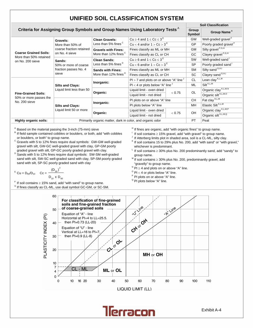
Site Plan and Boring Locations Diagram ..................................................................... A-1Field Exploration Description ....................................................................................... A-2General Notes ............................................................................................................. A-3Unified Soil Classification System ................................................................................ A-4Boring Logs ............................................................................................ A-5 through A-15
Appendix B – Laboratory TestingLaboratory Test Description ......................................................................................... B-1Atterberg Limits Results............................................................................................... B-2Grain Size Distribution .................................................................................... B-3 thru B-5Moisture-Density Relationship ........................................................................ B-6 and B-7Summary of Laboratory Results .................................................................................. B-8

Resourceful ■ Responsive ■ Reliable 1
GEOTECHNICAL ENGINEERING REPORTLONGMORE ROAD PEDESTRIAN IMPROVEMENTS
MCDOWELL ROAD TO OSBORN ROADSALT RIVER PIMA-MARICOPA INDIAN COMMUNITY, ARIZONA
Terracon Project No. 65155025June 17, 2016
1.0 INTRODUCTION
This report presents the results of our geotechnical engineering services for the proposedLongmore Road Pedestrian Improvements project in the Salt River Pima-Maricopa IndianCommunity (SRPMIC), Arizona. A Materials Design Report for the project has been preparedby Terracon Consultants, Inc. (Terracon) and issued under separate cover. The purpose ofthese services is to provide information and geotechnical engineering recommendations relativeto the planned earthwork and pavement improvements. The conclusions and recommendationsin this report are based on the results of field and laboratory testing, experience with similar soilconditions and pavements, and our understanding of the proposed project.
Our geotechnical engineering scope of work for this project included the advancement of 11shallow borings, laboratory testing, geotechnical and pavement engineering analysis, andpreparation of this report. Logs of the borings along with a Site Plan and Boring Locations diagram(Exhibit A-1) are included in Appendix A of this report. The results of the laboratory testingperformed on soil samples obtained from the site during the field exploration are included inAppendix B of this report. Descriptions of the field exploration and laboratory testing are includedin their respective appendices.
2.0 PROJECT INFORMATION
2.1 Site Description
ITEM DESCRIPTION
LocationThe project site is located along Longmore Road, betweenMcDowell Road and Osborn Road, on the Salt River Pima-Maricopa Indian Community, Arizona.

Geotechnical Engineering ReportLongmore Road Pedestrian Improvements ■ SRPMIC, ArizonaJune 17, 2016 ■ Terracon Project No. 65155025
Resourceful ■ Responsive ■ Reliable 2
ITEM DESCRIPTION
Existing Improvements
Longmore Road within the project limits is generally a two-laneasphalt concrete paved roadway with curb and gutter in someportions. There are scattered residential developments, commercialbuildings, and agricultural lands along the roadway alignment.There are driveways associated with the residential andcommercial properties.
Current Ground Cover Portland cement concrete, asphalt concrete, and bare soil.
Existing Topography Appears to be relatively flat.
2.2 Project Description
ITEM DESCRIPTION
Improvements
Pedestrian improvements to Longmore Road, located betweenMcDowell Road and Osborn Road, in the Salt River Pima-MaricopaIndian Community, Arizona. The project includes an 8-foot widesidewalk with trees and benches along Longmore Road for a lengthof about 1.5 miles and a short portion along Osborn Road, east ofLongmore Road. Minor widening to Longmore Road is planned insome locations and the pavement section will match the existingpavement section.
Grading Minor cuts and fills (less than 1-foot) are anticipated for the project.
3.0 SUBSURFACE CONDITIONS
3.1 Subsurface Soil Conditions
Specific conditions encountered at each boring location are indicated on the individual boring logsincluded in Appendix A of this report. Stratification boundaries on the boring logs represent theapproximate location of changes in soil types; in-situ, the transition between materials may begradual.
The borings were generally located outside of the roadway and along the proposed pedestrianpath alignment. Based on conditions encountered in the borings, subsurface conditions on theproject site can be generalized as follows:
Description Approximate Depth toBottom of Stratum (feet) Material Encountered
Stratum 10 to 3 (maximum depth
explored)Silty sand, clayey sand, and sandy clay with varying
gravel content, and no to weak cementation.

Geotechnical Engineering ReportLongmore Road Pedestrian Improvements ■ SRPMIC, ArizonaJune 17, 2016 ■ Terracon Project No. 65155025
Resourceful ■ Responsive ■ Reliable 3
Description Approximate Depth toBottom of Stratum (feet) Material Encountered
Undocumented fill was observed in borings B-3, B-8, and B-10 and extended to the total depthsexplored.
Laboratory tests consisting of grain size distribution, Atterberg Limits, and laboratory moisture-density relationships (Proctor) were conducted on selected soil samples and the test results aresummarized below and presented in Appendix B.
3.2 Existing Pavement Section
The existing Longmore Road is paved with asphalt concrete (AC) over aggregate base (AB)material. Based on the record drawings provided to us, the thickness of the existing pavementsection along the Longmore Road alignment consists of 4 inches of AC over 10 inches of AB.
3.3 Laboratory Test Data – Subgrade Soils
For purposes of subgrade evaluation, the results of the laboratory testing, including correlatedR-Values, are summarized in the following table:
SUMMARY OF TESTED AND CORRELATED R-VALUES
Boring Approx. Station; Offset Depth(ft.) LL PI -#200 R-Value Correlated
B-1 101+10; 30’R 0-3 26 2 42 51.8B-2 87+50; 40’L 0-3 23 2 33 58.6B-3 76+00; 40’L 0-0.8 NP NP 14 82.4B-4 67+50; 40’L 0-3 26 6 42 44.3B-5 60+25; 40’L 0-3 24 5 54 39.0B-6 51+30; 40’L 0-3 27 8 57 33.3B-7 43+00; 40’L 0-2 22 3 49 45.2B-8 35+00; 40’L 0-2 20 1 45 51.6B-9 27+50; 40’L 0-2.5 24 5 54 39.0
B-10 19+50; 30’L 0-1 25 4 41 48.5B-11 11+50; 30’L 0-3 25 6 60 34.5
Count 11Average 48.0
Standard Deviation 13.8

Geotechnical Engineering ReportLongmore Road Pedestrian Improvements ■ SRPMIC, ArizonaJune 17, 2016 ■ Terracon Project No. 65155025
Resourceful ■ Responsive ■ Reliable 4
4.0 RECOMMENDATIONS FOR DESIGN AND CONSTRUCTION
4.1 Geotechnical Considerations
Based on the site explorations and results of the laboratory testing, the subgrade soils in thesidewalk areas are considered suitable for support of the planned improvements. The followingsections present recommendations regarding pavement and earthwork construction.
4.2 Pavement Subgrade Parameters
The laboratory test data was used to establish one mean R-Value for pavement design withinthe project limits. The data indicates the subgrade soils at the site have good supportcharacteristics for the planned pavement sections. The calculated mean R-Value for the projectis 48, however we recommend an R-value of 25 be used for design purposes. Thecorresponding resilient modulus is 14,900 pounds per square inch (psi) for a seasonal variationfactor of 1.0 at the location of the project.
4.3 General Earthwork Considerations
The following presents recommendations for excavation and subgrade preparation on theproject. Earthwork on the project should be observed and evaluated by a licensed geotechnicalengineer. The evaluation of earthwork should include observation and testing of engineered fill,subgrade preparation, and other geotechnical conditions exposed during the construction of theproject.
It is anticipated that excavations for much of the proposed construction can be accomplishedwith conventional earthmoving equipment. Based upon the subsurface conditions determinedfrom the geotechnical exploration, the subgrade soils exposed during construction are expectedto be relatively stable. However, the stability of the subgrade may be affected by repetitiveconstruction traffic, moisture, or other factors.
Exposed areas which will receive fill, aggregate base course, or concrete sidewalk onceproperly cleared and benched where necessary, should be scarified to a minimum depth of six(6) inches, moisture conditioned, and compacted to a minimum of 95% of the maximum drydensity as determined by ARIZ 225 (standard Proctor) in accordance with ADOT specifications.Exposed surfaces should be free of mounds and depressions which could prevent uniformcompaction.
All fill that will be placed in the project should conform to the latest ADOT standard specificationsfor embankment material.

Geotechnical Engineering ReportLongmore Road Pedestrian Improvements ■ SRPMIC, ArizonaJune 17, 2016 ■ Terracon Project No. 65155025
Resourceful ■ Responsive ■ Reliable 5
4.4 Earthwork Factors and Slopes
Recommended cut slopes and shrinkage due to re-compaction of materials is presented in thefollowing table:
Location EarthworkFactor
Ground Compaction(feet)
Recommend Slope(horizontal: vertical)
Longmore Road 15% shrink 0.2Fill Slopes: 3:1, or flatterCut Slopes: 3:1, or flatter
Construction of fill slopes should be in accordance with Section 203-10 of the ADOT StandardSpecifications (ADOT, 2008). Slopes constructed at slope inclinations steeper than 3H:1Vshould have surface erosion measures considered in the design.
The face of all slopes should be compacted to the minimum specification for fillembankments. Fill slopes can be over-built and trimmed to expose a compacted slope surface.
4.5 Water
For balancing grading plans, approximately 90 gallons of water per cubic yard should beestimated for compaction of base materials. Approximately 90 gallons of water per cubic yardshould be estimated for compaction of subgrade materials.
The application of water estimated for subgrade materials is considerably higher than theamount calculated based upon the difference between in-situ and optimum compaction moisturecontent, and includes a conservative overrun for losses due to seepage, evaporation,inadequate mixing, spillage, etc. Precipitation during and/or before construction, or otherweather conditions may reduce the required amount of water.
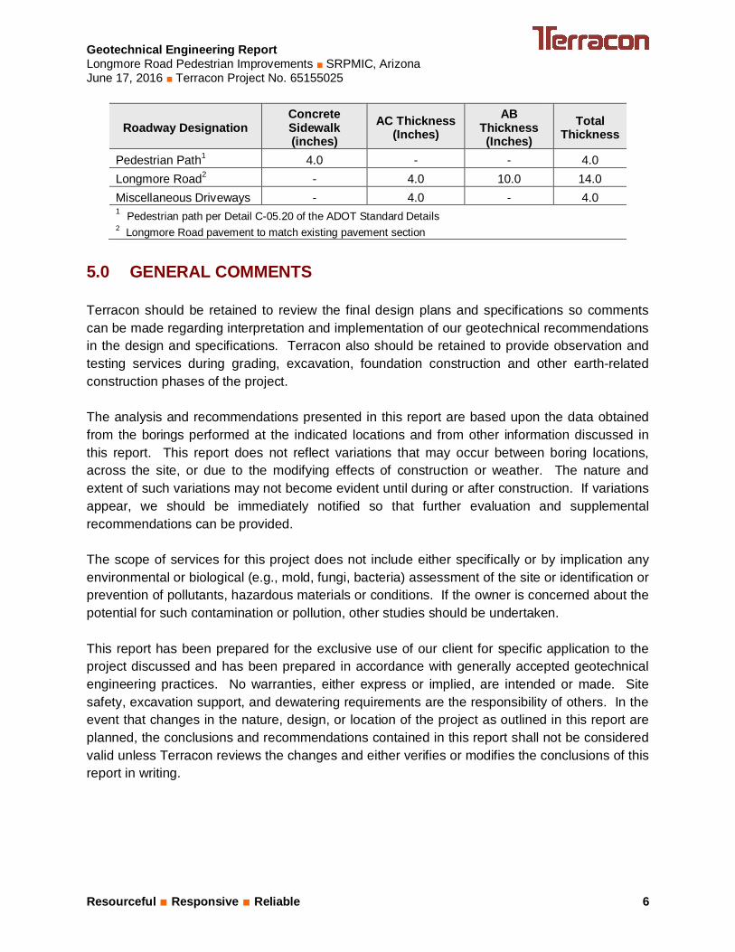
4.6 Pavement Thickness Recommendations
We recommend the pavement thicknesses presented in the table below be used for the project.Pavement thickness recommendations for Longmore Road and miscellaneous driveways arebased on the record drawings we received and local standards. Traffic count information wasnot available for this project. Pavement design analyses using traffic loading information was notperformed to verify the pavement thickness is adequate to support the traffic loading over aparticular design period. As such, increased pavement inspection and/or maintenance shouldbe anticipated based on traffic loading, weather effects, and other site conditions.
Geotechnical Engineering ReportLongmore Road Pedestrian Improvements ■ SRPMIC, ArizonaJune 17, 2016 ■ Terracon Project No. 65155025
Resourceful ■ Responsive ■ Reliable 6
Roadway DesignationConcreteSidewalk(inches)
AC Thickness(Inches)
ABThickness(Inches)
TotalThickness
Pedestrian Path1 4.0 - - 4.0Longmore Road2 - 4.0 10.0 14.0Miscellaneous Driveways - 4.0 - 4.01 Pedestrian path per Detail C-05.20 of the ADOT Standard Details2 Longmore Road pavement to match existing pavement section
5.0 GENERAL COMMENTS
Terracon should be retained to review the final design plans and specifications so commentscan be made regarding interpretation and implementation of our geotechnical recommendationsin the design and specifications. Terracon also should be retained to provide observation andtesting services during grading, excavation, foundation construction and other earth-relatedconstruction phases of the project.
The analysis and recommendations presented in this report are based upon the data obtainedfrom the borings performed at the indicated locations and from other information discussed inthis report. This report does not reflect variations that may occur between boring locations,across the site, or due to the modifying effects of construction or weather. The nature andextent of such variations may not become evident until during or after construction. If variationsappear, we should be immediately notified so that further evaluation and supplementalrecommendations can be provided.
The scope of services for this project does not include either specifically or by implication anyenvironmental or biological (e.g., mold, fungi, bacteria) assessment of the site or identification orprevention of pollutants, hazardous materials or conditions. If the owner is concerned about thepotential for such contamination or pollution, other studies should be undertaken.
This report has been prepared for the exclusive use of our client for specific application to theproject discussed and has been prepared in accordance with generally accepted geotechnicalengineering practices. No warranties, either express or implied, are intended or made. Sitesafety, excavation support, and dewatering requirements are the responsibility of others. In theevent that changes in the nature, design, or location of the project as outlined in this report areplanned, the conclusions and recommendations contained in this report shall not be consideredvalid unless Terracon reviews the changes and either verifies or modifies the conclusions of thisreport in writing.

Geotechnical Engineering ReportLongmore Road Pedestrian Improvements ■ SRPMIC, ArizonaJune 17, 2016 ■ Terracon Project No. 65155025
Resourceful ■ Responsive ■ Reliable
APPENDIX AFIELD EXPLORATION

EXHIBIT
A-1Longmore Road Pedestrian Improvements
MCDOWELL ROAD TO OSBORN ROAD
SALT RIVER PIMA-MARICOPA INDIAN COMMUNITY ARIZONA
Consulting Engineers and Scientists
4685 South Ash Avenue, Suite H-4 Tempe, AZ 85282FAX. (480) 897-1133PH. (480) 897-8200
Project No.
Scale:
Date:
File No.
06/01/2016
65155025.DWG
AS SHOWN
65155025Project Mngr:
Approved By:
Checked By:
Drawn By:
KLP
KLP
KLJ
KLP
SCALE: 1" ≈ 850'
SITE PLAN AND BORING LOCATION DIAGRAM
N
LEGEND: BORING LOCATION
B-1
IMAGE SOURCE: MARICOPA COUNTY ONLINE HISTORICAL AERIAL MAPS, 2015
E. OAK ST.
E. THOMAS RD.
E. OSBORN RD.
N. LO
NG
MO
RE
R
D
E. McDOWEL RD.
B-2
B-3
B-4
B-5
B-6
B-7
B-8
B-9
B-10
B-11

Geotechnical Engineering ReportLongmore Road Pedestrian Improvements ■ SRPMIC, ArizonaJune 17, 2016 ■ Terracon Project No. 65155025
Resourceful ■ Responsive ■ Reliable Exhibit A-2
Field Exploration Description
A total of 11 borings were advanced at the site on May 18, 2016. The borings were advancedutilizing hand auger methods to depths of up to approximately 3 feet below the existing groundsurface. The approximate boring and pavement core locations are shown on the attached SitePlan and Boring Locations diagram, Exhibit A-1.
The borings were located in the field utilizing a general plan and measurements off of theexisting site features. The borings were backfilled with cuttings.
Continuous lithologic logs of each boring were recorded by the field geologist during the drillingoperations. At selected intervals, samples of the subsurface materials were taken by drivingsplit-spoon or ring-barrel samplers. Bulk samples of subsurface materials were also obtained.

TraceWithModifier
Water Level Aftera Specified Period of Time
GRAIN SIZE TERMINOLOGYRELATIVE PROPORTIONS OF SAND AND GRAVEL
TraceWithModifier
Standard Penetration orN-Value
Blows/Ft.
Descriptive Term(Consistency)
Loose
Very Stiff
Standard Penetration orN-Value
Blows/Ft.
Ring SamplerBlows/Ft.
Ring SamplerBlows/Ft.
Medium Dense
Dense
Very Dense
0 - 1 < 3
4 - 9 2 - 4 3 - 4
Medium-Stiff 5 - 9
30 - 50
WA
TE
R L
EV
EL
Auger Shelby Tube Split Spoon
RockCore
8 - 15
PLASTICITY DESCRIPTION
Term
< 1515 - 29> 30
Descriptive Term(s)of other constituents
Water InitiallyEncountered
Water Level After aSpecified Period of Time
Major Componentof Sample
Percent ofDry Weight
(More than 50% retained on No. 200 sieve.)Density determined by Standard Penetration Resistance
Includes gravels, sands and silts.
Hard
Very Loose 0 - 3 0 - 6 Very Soft
7 - 18 Soft
10 - 29 19 - 58
59 - 98 Stiff
less than 500
500 to 1,000
1,000 to 2,000
MacroCore
2,000 to 4,000
4,000 to 8,000> 99
LOCATION AND ELEVATION NOTES
SA
MP
LIN
G
FIE
LD
TE
ST
S
DESCRIPTION OF SYMBOLS AND ABBREVIATIONS
Descriptive Term(Density)
Non-plasticLowMediumHigh
BouldersCobblesGravelSandSilt or Clay
10 - 18
> 50 15 - 30 19 - 42
> 30 > 42
_
CONSISTENCY OF FINE-GRAINED SOILS
Hand Penetrometer
Torvane
Standard PenetrationTest (blows per foot)
N value
Photo-Ionization Detector
Organic Vapor Analyzer
(HP)
(T)
(b/f)
N
(PID)
(OVA)
(50% or more passing the No. 200 sieve.)Consistency determined by laboratory shear strength testing, field
visual-manual procedures or standard penetration resistance
DESCRIPTIVE SOIL CLASSIFICATION
> 8,000
Unless otherwise noted, Latitude and Longitude are approximately determined using a hand-held GPS device. The accuracyof such devices is variable. Surface elevation data annotated with +/- indicates that no actual topographical survey wasconducted to confirm the surface elevation. Instead, the surface elevation was approximately determined from topographicmaps of the area.
Soil classification is based on the Unified Soil Classification System. Coarse Grained Soils have more than 50% of their dryweight retained on a #200 sieve; their principal descriptors are: boulders, cobbles, gravel or sand. Fine Grained Soils haveless than 50% of their dry weight retained on a #200 sieve; they are principally described as clays if they are plastic, andsilts if they are slightly plastic or non-plastic. Major constituents may be added as modifiers and minor constituents may beadded according to the relative proportions based on grain size. In addition to gradation, coarse-grained soils are definedon the basis of their in-place relative density and fine-grained soils on the basis of their consistency.
Plasticity Index
01 - 1011 - 30
> 30
RELATIVE PROPORTIONS OF FINES
Descriptive Term(s)of other constituents
Percent ofDry Weight
< 55 - 12> 12
RELATIVE DENSITY OF COARSE-GRAINED SOILS
Particle Size
Over 12 in. (300 mm)12 in. to 3 in. (300mm to 75mm)3 in. to #4 sieve (75mm to 4.75 mm)#4 to #200 sieve (4.75mm to 0.075mmPassing #200 sieve (0.075mm)
ST
RE
NG
TH
TE
RM
S Unconfined CompressiveStrength, Qu, psf
4 - 8
GENERAL NOTES
ModifiedCalifornia
Ring Sampler
GrabSample
ModifiedDames & MooreRing Sampler
NoRecovery
Water levels indicated on the soil boringlogs are the levels measured in theborehole at the times indicated.Groundwater level variations will occurover time. In low permeability soils,accurate determination of groundwaterlevels is not possible with short termwater level observations.
Exhibit A-3
UNIFIED SOIL CLASSIFICATION SYSTEM
Criteria for Assigning Group Symbols and Group Names Using Laboratory Tests A Soil Classification
Group Symbol Group Name B
Coarse Grained Soils: More than 50% retained on No. 200 sieve
Gravels: More than 50% of coarse fraction retained on No. 4 sieve
Clean Gravels: Less than 5% fines C
Cu 4 and 1 Cc 3 E GW Well-graded gravel F Cu 4 and/or 1 Cc 3 E GP Poorly graded gravel F
Gravels with Fines: More than 12% fines C
Fines classify as ML or MH GM Silty gravel F,G,H Fines classify as CL or CH GC Clayey gravel F,G,H
Sands: 50% or more of coarse fraction passes No. 4 sieve
Clean Sands: Less than 5% fines D
Cu 6 and 1 Cc 3 E SW Well-graded sand I Cu 6 and/or 1 Cc 3 E SP Poorly graded sand I
Sands with Fines: More than 12% fines D
Fines classify as ML or MH SM Silty sand G,H,I Fines classify as CL or CH SC Clayey sand G,H,I
Fine-Grained Soils: 50% or more passes the No. 200 sieve
Silts and Clays: Liquid limit less than 50
Inorganic: PI 7 and plots on or above “A” line J CL Lean clay K,L,M PI 4 or plots below “A” line J ML Silt K,L,M
Organic: Liquid limit - oven dried
0.75 OL Organic clay K,L,M,N
Liquid limit - not dried Organic silt K,L,M,O
Silts and Clays: Liquid limit 50 or more
Inorganic: PI plots on or above “A” line CH Fat clay K,L,M PI plots below “A” line MH Elastic Silt K,L,M
Organic: Liquid limit - oven dried
0.75 OH Organic clay K,L,M,P
Liquid limit - not dried Organic silt K,L,M,Q Highly organic soils: Primarily organic matter, dark in color, and organic odor PT Peat
A Based on the material passing the 3-inch (75-mm) sieve B If field sample contained cobbles or boulders, or both, add “with cobbles
or boulders, or both” to group name. C Gravels with 5 to 12% fines require dual symbols: GW-GM well-graded
gravel with silt, GW-GC well-graded gravel with clay, GP-GM poorly graded gravel with silt, GP-GC poorly graded gravel with clay.
D Sands with 5 to 12% fines require dual symbols: SW-SM well-graded sand with silt, SW-SC well-graded sand with clay, SP-SM poorly graded sand with silt, SP-SC poorly graded sand with clay
E Cu = D60/D10 Cc = 6010
2
30
DxD
)(D
F If soil contains 15% sand, add “with sand” to group name. G If fines classify as CL-ML, use dual symbol GC-GM, or SC-SM.
H If fines are organic, add “with organic fines” to group name. I If soil contains 15% gravel, add “with gravel” to group name. J If Atterberg limits plot in shaded area, soil is a CL-ML, silty clay. K If soil contains 15 to 29% plus No. 200, add “with sand” or “with gravel,”
whichever is predominant. L If soil contains 30% plus No. 200 predominantly sand, add “sandy” to
group name. M If soil contains 30% plus No. 200, predominantly gravel, add
“gravelly” to group name. N PI 4 and plots on or above “A” line. O PI 4 or plots below “A” line. P PI plots on or above “A” line. Q PI plots below “A” line.
Exhibit A-4

42
8 96
26-24-2
3.0
SILTY SAND (SM), brown
Boring Terminated at 3 Feet
Stratification lines are approximate. In-situ, the transition may be gradual.
GR
AP
HIC
LO
G
TH
IS B
OR
ING
LO
G IS
NO
T V
ALI
D IF
SE
PA
RA
TE
D F
RO
M O
RIG
INA
L R
EP
OR
T.
G
EO
SM
AR
T L
OG
-NO
WE
LL 6
515
502
5.G
PJ
TE
RR
AC
ON
2015
.GD
T
6/17
/16
SITE:
Page 1 of 1
Advancement Method:Hand Auger
Abandonment Method:Borings backfilled with soil cuttings upon completion.
4685 S Ash Ave Ste H-4Tempe, AZ
Notes:
Project No.: 65155025
Drill Rig: Hand Auger
Boring Started: 5/18/2016
BORING LOG NO. B-1Engineering and Environmental Consultants, Inc.CLIENT:Tucson, Arizona
Driller: Terracon
Boring Completed: 5/18/2016
Exhibit: A-5
See Exhibit A-2 for description of fieldproceduresSee Appendix B for description of laboratoryprocedures and additional data (if any).
See Appendix A for explanation of symbols andabbreviations.
McDowell Road to Osborn Road SRPMIC, Arizona
PROJECT: Longmore Road Pedestrian Improvements
PE
RC
EN
T F
INE
S
WA
TE
RC
ON
TE
NT
(%
)
DR
Y U
NIT
WE
IGH
T (
pcf)
ATTERBERGLIMITS
LL-PL-PI
SA
MP
LE T
YP
E
WA
TE
R L
EV
EL
OB
SE
RV
AT
ION
S
DE
PT
H (
Ft.)
FIE
LD T
ES
TR
ES
ULT
S
DEPTH
LOCATION See Exhibit A-1
Station: 101+10 Offset: 30'R
Latitude: 33.48768° Longitude: -111.86489°
Groundwater not encounteredWATER LEVEL OBSERVATIONS

33
6 98
23-21-2
3.0
SILTY SAND WITH GRAVEL (SM), brown
Boring Terminated at 3 Feet
Stratification lines are approximate. In-situ, the transition may be gradual.
GR
AP
HIC
LO
G
TH
IS B
OR
ING
LO
G IS
NO
T V
ALI
D IF
SE
PA
RA
TE
D F
RO
M O
RIG
INA
L R
EP
OR
T.
G
EO
SM
AR
T L
OG
-NO
WE
LL 6
515
502
5.G
PJ
TE
RR
AC
ON
2015
.GD
T
6/17
/16
SITE:
Page 1 of 1
Advancement Method:Hand Auger
Abandonment Method:Borings backfilled with soil cuttings upon completion.
4685 S Ash Ave Ste H-4Tempe, AZ
Notes:
Project No.: 65155025
Drill Rig: Hand Auger
Boring Started: 5/18/2016
BORING LOG NO. B-2Engineering and Environmental Consultants, Inc.CLIENT:Tucson, Arizona
Driller: Terracon
Boring Completed: 5/18/2016
Exhibit: A-6
See Exhibit A-2 for description of fieldproceduresSee Appendix B for description of laboratoryprocedures and additional data (if any).
See Appendix A for explanation of symbols andabbreviations.
McDowell Road to Osborn Road SRPMIC, Arizona
PROJECT: Longmore Road Pedestrian Improvements
PE
RC
EN
T F
INE
S
WA
TE
RC
ON
TE
NT
(%
)
DR
Y U
NIT
WE
IGH
T (
pcf)
ATTERBERGLIMITS
LL-PL-PI
SA
MP
LE T
YP
E
WA
TE
R L
EV
EL
OB
SE
RV
AT
ION
S
DE
PT
H (
Ft.)
FIE
LD T
ES
TR
ES
ULT
S
DEPTH
LOCATION See Exhibit A-1
Station: 87+50 Offset: 40'L
Latitude: 33.48682° Longitude: -111.8654°
Groundwater not encounteredWATER LEVEL OBSERVATIONS

14NP
0.8
FILL - SILTY SAND WITH GRAVEL (SM), brown
Auger Refusal at 0.8 Foot
Stratification lines are approximate. In-situ, the transition may be gradual.
GR
AP
HIC
LO
G
TH
IS B
OR
ING
LO
G IS
NO
T V
ALI
D IF
SE
PA
RA
TE
D F
RO
M O
RIG
INA
L R
EP
OR
T.
G
EO
SM
AR
T L
OG
-NO
WE
LL 6
515
502
5.G
PJ
TE
RR
AC
ON
2015
.GD
T
6/17
/16
SITE:
Page 1 of 1
Advancement Method:Hand Auger
Abandonment Method:Borings backfilled with soil cuttings upon completion.
4685 S Ash Ave Ste H-4Tempe, AZ
Notes:
Project No.: 65155025
Drill Rig: Hand Auger
Boring Started: 5/18/2016
BORING LOG NO. B-3Engineering and Environmental Consultants, Inc.CLIENT:Tucson, Arizona
Driller: Terracon
Boring Completed: 5/18/2016
Exhibit: A-7
See Exhibit A-2 for description of fieldproceduresSee Appendix B for description of laboratoryprocedures and additional data (if any).
See Appendix A for explanation of symbols andabbreviations.
McDowell Road to Osborn Road SRPMIC, Arizona
PROJECT: Longmore Road Pedestrian Improvements
PE
RC
EN
T F
INE
S
WA
TE
RC
ON
TE
NT
(%
)
DR
Y U
NIT
WE
IGH
T (
pcf)
ATTERBERGLIMITS
LL-PL-PI
SA
MP
LE T
YP
E
WA
TE
R L
EV
EL
OB
SE
RV
AT
ION
S
DE
PT
H (
Ft.)
FIE
LD T
ES
TR
ES
ULT
S
DEPTH
LOCATION See Exhibit A-1
Station: 76+00 Offset: 40'L
Latitude: 33.48368° Longitude: -111.86546°
Groundwater not encounteredWATER LEVEL OBSERVATIONS
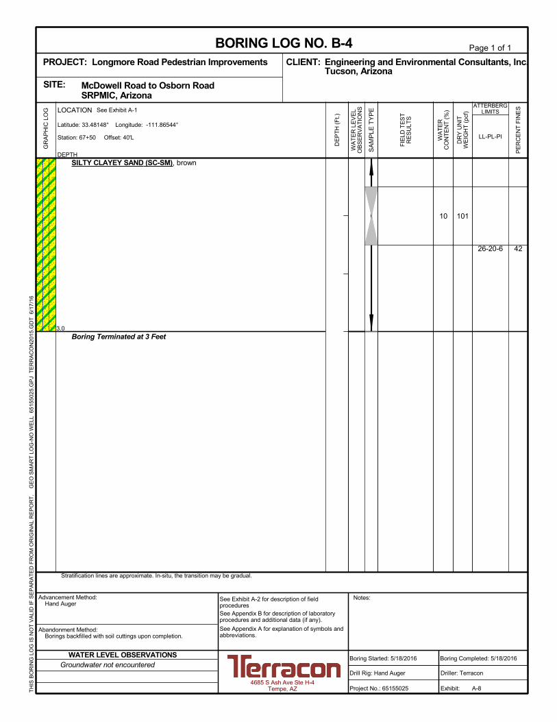
42
10 101
26-20-6
3.0
SILTY CLAYEY SAND (SC-SM), brown
Boring Terminated at 3 Feet
Stratification lines are approximate. In-situ, the transition may be gradual.
GR
AP
HIC
LO
G
TH
IS B
OR
ING
LO
G IS
NO
T V
ALI
D IF
SE
PA
RA
TE
D F
RO
M O
RIG
INA
L R
EP
OR
T.
G
EO
SM
AR
T L
OG
-NO
WE
LL 6
515
502
5.G
PJ
TE
RR
AC
ON
2015
.GD
T
6/17
/16
SITE:
Page 1 of 1
Advancement Method:Hand Auger
Abandonment Method:Borings backfilled with soil cuttings upon completion.
4685 S Ash Ave Ste H-4Tempe, AZ
Notes:
Project No.: 65155025
Drill Rig: Hand Auger
Boring Started: 5/18/2016
BORING LOG NO. B-4Engineering and Environmental Consultants, Inc.CLIENT:Tucson, Arizona
Driller: Terracon
Boring Completed: 5/18/2016
Exhibit: A-8
See Exhibit A-2 for description of fieldproceduresSee Appendix B for description of laboratoryprocedures and additional data (if any).
See Appendix A for explanation of symbols andabbreviations.
McDowell Road to Osborn Road SRPMIC, Arizona
PROJECT: Longmore Road Pedestrian Improvements
PE
RC
EN
T F
INE
S
WA
TE
RC
ON
TE
NT
(%
)
DR
Y U
NIT
WE
IGH
T (
pcf)
ATTERBERGLIMITS
LL-PL-PI
SA
MP
LE T
YP
E
WA
TE
R L
EV
EL
OB
SE
RV
AT
ION
S
DE
PT
H (
Ft.)
FIE
LD T
ES
TR
ES
ULT
S
DEPTH
LOCATION See Exhibit A-1
Station: 67+50 Offset: 40'L
Latitude: 33.48148° Longitude: -111.86544°
Groundwater not encounteredWATER LEVEL OBSERVATIONS

5424-19-5
3.0
SANDY SILTY CLAY (CL-ML), brown, weak to moderate cementation
Boring Terminated at 3 Feet
Stratification lines are approximate. In-situ, the transition may be gradual.
GR
AP
HIC
LO
G
TH
IS B
OR
ING
LO
G IS
NO
T V
ALI
D IF
SE
PA
RA
TE
D F
RO
M O
RIG
INA
L R
EP
OR
T.
G
EO
SM
AR
T L
OG
-NO
WE
LL 6
515
502
5.G
PJ
TE
RR
AC
ON
2015
.GD
T
6/17
/16
SITE:
Page 1 of 1
Advancement Method:Hand Auger
Abandonment Method:Borings backfilled with soil cuttings upon completion.
4685 S Ash Ave Ste H-4Tempe, AZ
Notes:
Project No.: 65155025
Drill Rig: Hand Auger
Boring Started: 5/18/2016
BORING LOG NO. B-5Engineering and Environmental Consultants, Inc.CLIENT:Tucson, Arizona
Driller: Terracon
Boring Completed: 5/18/2016
Exhibit: A-9
See Exhibit A-2 for description of fieldproceduresSee Appendix B for description of laboratoryprocedures and additional data (if any).
See Appendix A for explanation of symbols andabbreviations.
McDowell Road to Osborn Road SRPMIC, Arizona
PROJECT: Longmore Road Pedestrian Improvements
PE
RC
EN
T F
INE
S
WA
TE
RC
ON
TE
NT
(%
)
DR
Y U
NIT
WE
IGH
T (
pcf)
ATTERBERGLIMITS
LL-PL-PI
SA
MP
LE T
YP
E
WA
TE
R L
EV
EL
OB
SE
RV
AT
ION
S
DE
PT
H (
Ft.)
FIE
LD T
ES
TR
ES
ULT
S
DEPTH
LOCATION See Exhibit A-1
Station: 60+25 Offset: 40'L
Latitude: 33.47929° Longitude: -111.86543°
Groundwater not encounteredWATER LEVEL OBSERVATIONS

57
9 88
27-19-8
3.0
SANDY LEAN CLAY (CL), brown
Boring Terminated at 3 Feet
Stratification lines are approximate. In-situ, the transition may be gradual.
GR
AP
HIC
LO
G
TH
IS B
OR
ING
LO
G IS
NO
T V
ALI
D IF
SE
PA
RA
TE
D F
RO
M O
RIG
INA
L R
EP
OR
T.
G
EO
SM
AR
T L
OG
-NO
WE
LL 6
515
502
5.G
PJ
TE
RR
AC
ON
2015
.GD
T
6/17
/16
SITE:
Page 1 of 1
Advancement Method:Hand Auger
Abandonment Method:Borings backfilled with soil cuttings upon completion.
4685 S Ash Ave Ste H-4Tempe, AZ
Notes:
Project No.: 65155025
Drill Rig: Hand Auger
Boring Started: 5/18/2016
BORING LOG NO. B-6Engineering and Environmental Consultants, Inc.CLIENT:Tucson, Arizona
Driller: Terracon
Boring Completed: 5/18/2016
Exhibit: A-10
See Exhibit A-2 for description of fieldproceduresSee Appendix B for description of laboratoryprocedures and additional data (if any).
See Appendix A for explanation of symbols andabbreviations.
McDowell Road to Osborn Road SRPMIC, Arizona
PROJECT: Longmore Road Pedestrian Improvements
PE
RC
EN
T F
INE
S
WA
TE
RC
ON
TE
NT
(%
)
DR
Y U
NIT
WE
IGH
T (
pcf)
ATTERBERGLIMITS
LL-PL-PI
SA
MP
LE T
YP
E
WA
TE
R L
EV
EL
OB
SE
RV
AT
ION
S
DE
PT
H (
Ft.)
FIE
LD T
ES
TR
ES
ULT
S
DEPTH
LOCATION See Exhibit A-1
Station: 51+30 Offset: 40'L
Latitude: 33.4771° Longitude: -111.86542°
Groundwater not encounteredWATER LEVEL OBSERVATIONS

4922-19-3
2.0
SILTY SAND (SM), brown, calcite cemented nodules
Auger Refusal at 2 Feet
Stratification lines are approximate. In-situ, the transition may be gradual.
GR
AP
HIC
LO
G
TH
IS B
OR
ING
LO
G IS
NO
T V
ALI
D IF
SE
PA
RA
TE
D F
RO
M O
RIG
INA
L R
EP
OR
T.
G
EO
SM
AR
T L
OG
-NO
WE
LL 6
515
502
5.G
PJ
TE
RR
AC
ON
2015
.GD
T
6/17
/16
SITE:
Page 1 of 1
Advancement Method:Hand Auger
Abandonment Method:Borings backfilled with soil cuttings upon completion.
4685 S Ash Ave Ste H-4Tempe, AZ
Notes:
Project No.: 65155025
Drill Rig: Hand Auger
Boring Started: 5/18/2016
BORING LOG NO. B-7Engineering and Environmental Consultants, Inc.CLIENT:Tucson, Arizona
Driller: Terracon
Boring Completed: 5/18/2016
Exhibit: A-11
See Exhibit A-2 for description of fieldproceduresSee Appendix B for description of laboratoryprocedures and additional data (if any).
See Appendix A for explanation of symbols andabbreviations.
McDowell Road to Osborn Road SRPMIC, Arizona
PROJECT: Longmore Road Pedestrian Improvements
PE
RC
EN
T F
INE
S
WA
TE
RC
ON
TE
NT
(%
)
DR
Y U
NIT
WE
IGH
T (
pcf)
ATTERBERGLIMITS
LL-PL-PI
SA
MP
LE T
YP
E
WA
TE
R L
EV
EL
OB
SE
RV
AT
ION
S
DE
PT
H (
Ft.)
FIE
LD T
ES
TR
ES
ULT
S
DEPTH
LOCATION See Exhibit A-1
Station: 43+00 Offset: 40'L
Latitude: 33.47486° Longitude: -111.86543°
Groundwater not encounteredWATER LEVEL OBSERVATIONS
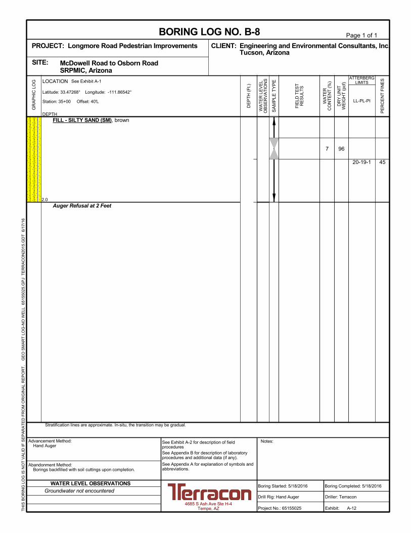
45
7 96
20-19-1
2.0
FILL - SILTY SAND (SM), brown
Auger Refusal at 2 Feet
Stratification lines are approximate. In-situ, the transition may be gradual.
GR
AP
HIC
LO
G
TH
IS B
OR
ING
LO
G IS
NO
T V
ALI
D IF
SE
PA
RA
TE
D F
RO
M O
RIG
INA
L R
EP
OR
T.
G
EO
SM
AR
T L
OG
-NO
WE
LL 6
515
502
5.G
PJ
TE
RR
AC
ON
2015
.GD
T
6/17
/16
SITE:
Page 1 of 1
Advancement Method:Hand Auger
Abandonment Method:Borings backfilled with soil cuttings upon completion.
4685 S Ash Ave Ste H-4Tempe, AZ
Notes:
Project No.: 65155025
Drill Rig: Hand Auger
Boring Started: 5/18/2016
BORING LOG NO. B-8Engineering and Environmental Consultants, Inc.CLIENT:Tucson, Arizona
Driller: Terracon
Boring Completed: 5/18/2016
Exhibit: A-12
See Exhibit A-2 for description of fieldproceduresSee Appendix B for description of laboratoryprocedures and additional data (if any).
See Appendix A for explanation of symbols andabbreviations.
McDowell Road to Osborn Road SRPMIC, Arizona
PROJECT: Longmore Road Pedestrian Improvements
PE
RC
EN
T F
INE
S
WA
TE
RC
ON
TE
NT
(%
)
DR
Y U
NIT
WE
IGH
T (
pcf)
ATTERBERGLIMITS
LL-PL-PI
SA
MP
LE T
YP
E
WA
TE
R L
EV
EL
OB
SE
RV
AT
ION
S
DE
PT
H (
Ft.)
FIE
LD T
ES
TR
ES
ULT
S
DEPTH
LOCATION See Exhibit A-1
Station: 35+00 Offset: 40'L
Latitude: 33.47268° Longitude: -111.86542°
Groundwater not encounteredWATER LEVEL OBSERVATIONS

54
10 93
24-19-5
2.5
SANDY SILTY CLAY (CL-ML), brown
Auger Refusal at 2.5 Feet
Stratification lines are approximate. In-situ, the transition may be gradual.
GR
AP
HIC
LO
G
TH
IS B
OR
ING
LO
G IS
NO
T V
ALI
D IF
SE
PA
RA
TE
D F
RO
M O
RIG
INA
L R
EP
OR
T.
G
EO
SM
AR
T L
OG
-NO
WE
LL 6
515
502
5.G
PJ
TE
RR
AC
ON
2015
.GD
T
6/17
/16
SITE:
Page 1 of 1
Advancement Method:Hand Auger
Abandonment Method:Borings backfilled with soil cuttings upon completion.
4685 S Ash Ave Ste H-4Tempe, AZ
Notes:
Project No.: 65155025
Drill Rig: Hand Auger
Boring Started: 5/18/2016
BORING LOG NO. B-9Engineering and Environmental Consultants, Inc.CLIENT:Tucson, Arizona
Driller: Terracon
Boring Completed: 5/18/2016
Exhibit: A-13
See Exhibit A-2 for description of fieldproceduresSee Appendix B for description of laboratoryprocedures and additional data (if any).
See Appendix A for explanation of symbols andabbreviations.
McDowell Road to Osborn Road SRPMIC, Arizona
PROJECT: Longmore Road Pedestrian Improvements
PE
RC
EN
T F
INE
S
WA
TE
RC
ON
TE
NT
(%
)
DR
Y U
NIT
WE
IGH
T (
pcf)
ATTERBERGLIMITS
LL-PL-PI
SA
MP
LE T
YP
E
WA
TE
R L
EV
EL
OB
SE
RV
AT
ION
S
DE
PT
H (
Ft.)
FIE
LD T
ES
TR
ES
ULT
S
DEPTH
LOCATION See Exhibit A-1
Station: 27+50 Offset: 40'L
Latitude: 33.47049° Longitude: -111.86541°
Groundwater not encounteredWATER LEVEL OBSERVATIONS

41
8 81
25-21-4
1.0
FILL - SILTY CLAYEY SAND WITH GRAVEL (SC-SM), brown
Auger Refusal at 1 Foot
Stratification lines are approximate. In-situ, the transition may be gradual.
GR
AP
HIC
LO
G
TH
IS B
OR
ING
LO
G IS
NO
T V
ALI
D IF
SE
PA
RA
TE
D F
RO
M O
RIG
INA
L R
EP
OR
T.
G
EO
SM
AR
T L
OG
-NO
WE
LL 6
515
502
5.G
PJ
TE
RR
AC
ON
2015
.GD
T
6/17
/16
SITE:
Page 1 of 1
Advancement Method:Hand Auger
Abandonment Method:Borings backfilled with soil cuttings upon completion.
4685 S Ash Ave Ste H-4Tempe, AZ
Notes:
Project No.: 65155025
Drill Rig: Hand Auger
Boring Started: 5/18/2016
BORING LOG NO. B-10Engineering and Environmental Consultants, Inc.CLIENT:Tucson, Arizona
Driller: Terracon
Boring Completed: 5/18/2016
Exhibit: A-14
See Exhibit A-2 for description of fieldproceduresSee Appendix B for description of laboratoryprocedures and additional data (if any).
See Appendix A for explanation of symbols andabbreviations.
McDowell Road to Osborn Road SRPMIC, Arizona
PROJECT: Longmore Road Pedestrian Improvements
PE
RC
EN
T F
INE
S
WA
TE
RC
ON
TE
NT
(%
)
DR
Y U
NIT
WE
IGH
T (
pcf)
ATTERBERGLIMITS
LL-PL-PI
SA
MP
LE T
YP
E
WA
TE
R L
EV
EL
OB
SE
RV
AT
ION
S
DE
PT
H (
Ft.)
FIE
LD T
ES
TR
ES
ULT
S
DEPTH
LOCATION See Exhibit A-1
Station: 19+50 Offset: 30'L
Latitude: 33.46838° Longitude: -111.86579°
Groundwater not encounteredWATER LEVEL OBSERVATIONS
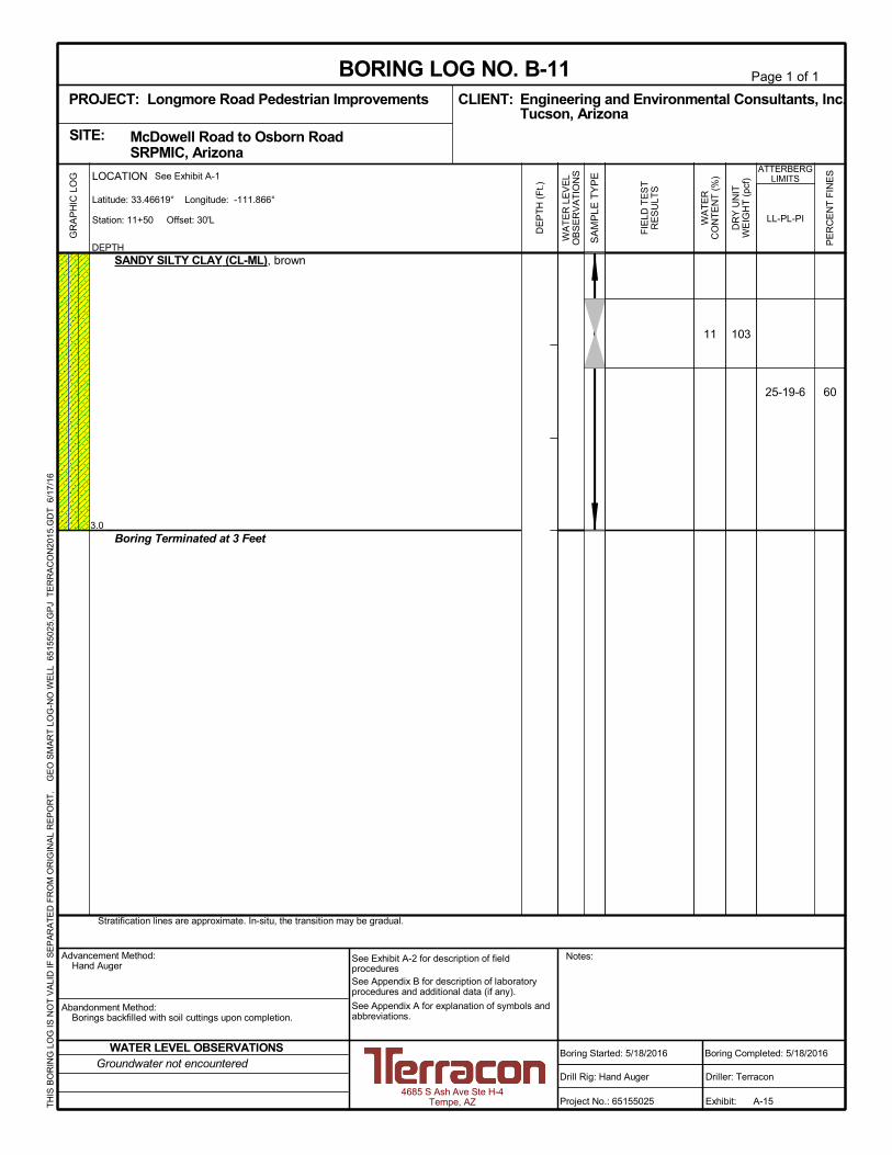
60
11 103
25-19-6
3.0
SANDY SILTY CLAY (CL-ML), brown
Boring Terminated at 3 Feet
Stratification lines are approximate. In-situ, the transition may be gradual.
GR
AP
HIC
LO
G
TH
IS B
OR
ING
LO
G IS
NO
T V
ALI
D IF
SE
PA
RA
TE
D F
RO
M O
RIG
INA
L R
EP
OR
T.
G
EO
SM
AR
T L
OG
-NO
WE
LL 6
515
502
5.G
PJ
TE
RR
AC
ON
2015
.GD
T
6/17
/16
SITE:
Page 1 of 1
Advancement Method:Hand Auger
Abandonment Method:Borings backfilled with soil cuttings upon completion.
4685 S Ash Ave Ste H-4Tempe, AZ
Notes:
Project No.: 65155025
Drill Rig: Hand Auger
Boring Started: 5/18/2016
BORING LOG NO. B-11Engineering and Environmental Consultants, Inc.CLIENT:Tucson, Arizona
Driller: Terracon
Boring Completed: 5/18/2016
Exhibit: A-15
See Exhibit A-2 for description of fieldproceduresSee Appendix B for description of laboratoryprocedures and additional data (if any).
See Appendix A for explanation of symbols andabbreviations.
McDowell Road to Osborn Road SRPMIC, Arizona
PROJECT: Longmore Road Pedestrian Improvements
PE
RC
EN
T F
INE
S
WA
TE
RC
ON
TE
NT
(%
)
DR
Y U
NIT
WE
IGH
T (
pcf)
ATTERBERGLIMITS
LL-PL-PI
SA
MP
LE T
YP
E
WA
TE
R L
EV
EL
OB
SE
RV
AT
ION
S
DE
PT
H (
Ft.)
FIE
LD T
ES
TR
ES
ULT
S
DEPTH
LOCATION See Exhibit A-1
Station: 11+50 Offset: 30'L
Latitude: 33.46619° Longitude: -111.866°
Groundwater not encounteredWATER LEVEL OBSERVATIONS

Geotechnical Engineering ReportLongmore Road Pedestrian Improvements ■ SRPMIC, ArizonaJune 17, 2016 ■ Terracon Project No. 65155025
Resourceful ■ Responsive ■ Reliable
APPENDIX BLABORATORY TESTING

Geotechnical Engineering ReportLongmore Road Pedestrian Improvements ■ SRPMIC, ArizonaJune 17, 2016 ■ Terracon Project No. 65155025
Resourceful ■ Responsive ■ Reliable Exhibit B-1
Laboratory Testing
Samples retrieved during the field exploration were taken to the laboratory for furtherobservation by the project geotechnical engineer and were classified in accordance with theUnified Soil Classification System (USCS) described in Appendix A. At that time, the fielddescriptions were confirmed or modified as necessary and an applicable laboratory testingprogram was formulated to determine engineering properties of the subsurface materials.
Laboratory tests were conducted on selected soil samples and the test results are presented inthis appendix. The laboratory test results were used for the geotechnical engineering analyses,and the development of recommendations. Laboratory tests were performed in generalaccordance with the applicable ASTM, local or other accepted standards.
Selected soil samples obtained from the site were tested for the following engineeringproperties:
n Atterberg Limits n Sieve Analysisn Laboratory Moisture-Density Relationships
(Proctor)n Unit Weight
n Moisture Content

0
10
20
30
40
50
60
0 20 40 60 80 100
CH o
r
OH
CL o
r
OL
ML or OL
MH or OH
PL PIBoring ID Depth Description
SILTY SAND
SILTY SAND
SILTY SAND with GRAVEL
SILTY, CLAYEY SAND
SANDY SILTY CLAY
SANDY LEAN CLAY
SILTY SAND
SILTY SAND
SANDY SILTY CLAY
SILTY, CLAYEY SAND with GRAVEL
SANDY SILTY CLAY
SM
SM
SM
SC-SM
CL-ML
CL
SM
SM
CL-ML
SC-SM
CL-ML
Fines
PLASTICITY
INDEX
LIQUID LIMIT
"U" L
ine
"A" L
ine
26
23
NP
26
24
27
22
20
24
25
25
24
21
NP
20
19
19
19
19
19
21
19
2
2
NP
6
5
8
3
1
5
4
6
42
33
14
42
54
57
49
45
54
41
60
LL USCS
B-1
B-2
B-3
B-4
B-5
B-6
B-7
B-8
B-9
B-10
B-11
ATTERBERG LIMITS RESULTSASTM D4318
0 - 3
0 - 3
0 - 0.8
0 - 3
0 - 3
0 - 3
0 - 2
0 - 2
0 - 2.5
0 - 1
0 - 3
4685 S Ash Ave Ste H-4Tempe, AZ
PROJECT NUMBER: 65155025PROJECT: Longmore Road Pedestrian
Improvements
SITE: McDowell Road to Osborn Road SRPMIC, Arizona
CLIENT: Engineering and EnvironmentalConsultants, Inc. Tucson, Arizona
EXHIBIT: B-2
LAB
OR
AT
OR
Y T
ES
TS
AR
E N
OT
VA
LID
IF S
EP
AR
AT
ED
FR
OM
OR
IGIN
AL
RE
PO
RT
.
AT
TE
RB
ER
G L
IMIT
S 6
5155
025.
GP
J T
ER
RA
CO
N20
15.G
DT
6/
17/1
6
CL-ML
0
5
10
15
20
25
30
35
40
45
50
55
60
65
70
75
80
85
90
95
100
0.0010.010.1110100
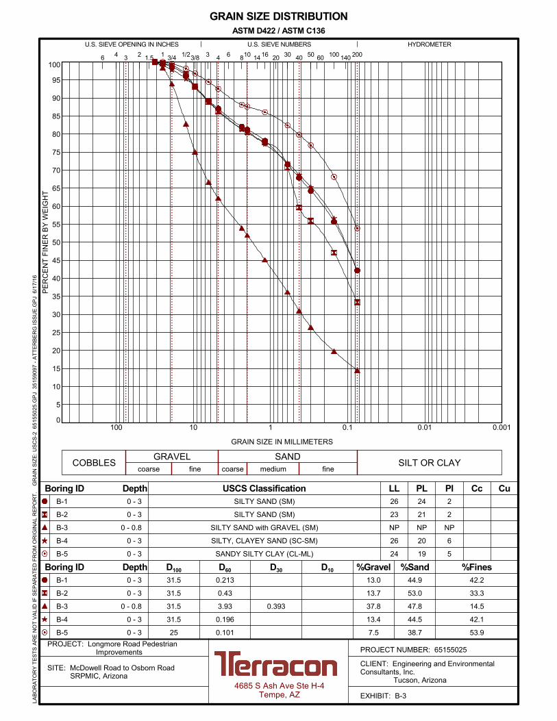
B-1
B-2
B-3
B-4
B-5
26
23
NP
26
24
0.393
0.213
0.43
3.93
0.196
0.101
31.5
31.5
31.5
31.5
25
6 16 20 30 40 501.5 2006 810
13.0
13.7
37.8
13.4
7.5
14
42.2
33.3
14.5
42.1
53.9
%Fines
LL PL PI
41 3/4 1/2 60
fine
B-1
B-2
B-3
B-4
B-5
GRAIN SIZE IN MILLIMETERS
PE
RC
EN
T F
INE
R B
Y W
EIG
HT
coarse fine
HYDROMETERU.S. SIEVE OPENING IN INCHES U.S. SIEVE NUMBERS
24
21
NP
20
19
2
2
NP
6
5
D100
Cc Cu
SILT OR CLAY
4
%Sand%GravelD30 D10
0 - 3
0 - 3
0 - 0.8
0 - 3
0 - 3
3/8 3 100 1403 2
COBBLESGRAVEL SAND
USCS Classification
44.9
53.0
47.8
44.5
38.7
D60
coarse medium
Boring ID Depth
Boring ID Depth
GRAIN SIZE DISTRIBUTION
0 - 3
0 - 3
0 - 0.8
0 - 3
0 - 3
SILTY SAND (SM)
SILTY SAND (SM)
SILTY SAND with GRAVEL (SM)
SILTY, CLAYEY SAND (SC-SM)
SANDY SILTY CLAY (CL-ML)
ASTM D422 / ASTM C136
4685 S Ash Ave Ste H-4Tempe, AZ
PROJECT NUMBER: 65155025PROJECT: Longmore Road Pedestrian
Improvements
SITE: McDowell Road to Osborn Road SRPMIC, Arizona
CLIENT: Engineering and EnvironmentalConsultants, Inc. Tucson, Arizona
EXHIBIT: B-3
LAB
OR
AT
OR
Y T
ES
TS
AR
E N
OT
VA
LID
IF S
EP
AR
AT
ED
FR
OM
OR
IGIN
AL
RE
PO
RT
.
GR
AIN
SIZ
E: U
SC
S-2
651
550
25.G
PJ
351
5909
7 -
AT
TE
RB
ER
G IS
SU
E.G
PJ
6/1
7/16

0
5
10
15
20
25
30
35
40
45
50
55
60
65
70
75
80
85
90
95
100
0.0010.010.1110100
B-6
B-7
B-8
B-9
B-10
27
22
20
24
25
0.09
0.122
0.136
0.098
0.305
25
31.5
31.5
37.5
31.5
6 16 20 30 40 501.5 2006 810
5.4
10.7
5.8
5.0
16.7
14
56.6
48.5
45.1
54.4
40.8
%Fines
LL PL PI
41 3/4 1/2 60
fine
B-6
B-7
B-8
B-9
B-10
GRAIN SIZE IN MILLIMETERS
PE
RC
EN
T F
INE
R B
Y W
EIG
HT
coarse fine
HYDROMETERU.S. SIEVE OPENING IN INCHES U.S. SIEVE NUMBERS
19
19
19
19
21
8
3
1
5
4
D100
Cc Cu
SILT OR CLAY
4
%Sand%GravelD30 D10
0 - 3
0 - 2
0 - 2
0 - 2.5
0 - 1
3/8 3 100 1403 2
COBBLESGRAVEL SAND
USCS Classification
38.0
40.8
49.1
40.6
42.5
D60
coarse medium
Boring ID Depth
Boring ID Depth
GRAIN SIZE DISTRIBUTION
0 - 3
0 - 2
0 - 2
0 - 2.5
0 - 1
SANDY LEAN CLAY (CL)
SILTY SAND (SM)
SILTY SAND (SM)
SANDY SILTY CLAY (CL-ML)
SILTY, CLAYEY SAND with GRAVEL (SC-SM)
ASTM D422 / ASTM C136
4685 S Ash Ave Ste H-4Tempe, AZ
PROJECT NUMBER: 65155025PROJECT: Longmore Road Pedestrian
Improvements
SITE: McDowell Road to Osborn Road SRPMIC, Arizona
CLIENT: Engineering and EnvironmentalConsultants, Inc. Tucson, Arizona
EXHIBIT: B-4
LAB
OR
AT
OR
Y T
ES
TS
AR
E N
OT
VA
LID
IF S
EP
AR
AT
ED
FR
OM
OR
IGIN
AL
RE
PO
RT
.
GR
AIN
SIZ
E: U
SC
S-2
651
550
25.G
PJ
351
5909
7 -
AT
TE
RB
ER
G IS
SU
E.G
PJ
6/1
7/16
0
5
10
15
20
25
30
35
40
45
50
55
60
65
70
75
80
85
90
95
100
0.0010.010.1110100
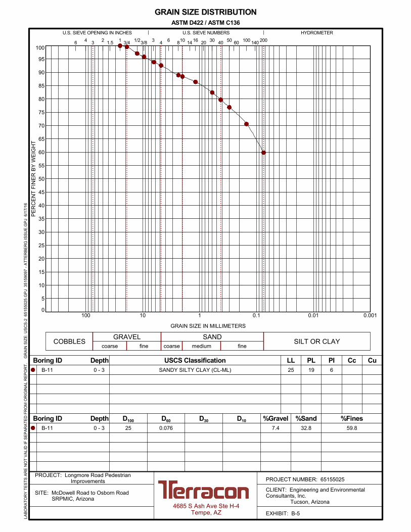
B-11 25
0.07625
6 16 20 30 40 501.5 2006 810
7.4
14
59.8
%Fines
LL PL PI
41 3/4 1/2 60
fine
B-11
GRAIN SIZE IN MILLIMETERS
PE
RC
EN
T F
INE
R B
Y W
EIG
HT
coarse fine
HYDROMETERU.S. SIEVE OPENING IN INCHES U.S. SIEVE NUMBERS
19 6
D100
Cc Cu
SILT OR CLAY
4
%Sand%GravelD30 D10
0 - 3
3/8 3 100 1403 2
COBBLESGRAVEL SAND
USCS Classification
32.8
D60
coarse medium
Boring ID Depth
Boring ID Depth
GRAIN SIZE DISTRIBUTION
0 - 3 SANDY SILTY CLAY (CL-ML)
ASTM D422 / ASTM C136
4685 S Ash Ave Ste H-4Tempe, AZ
PROJECT NUMBER: 65155025PROJECT: Longmore Road Pedestrian
Improvements
SITE: McDowell Road to Osborn Road SRPMIC, Arizona
CLIENT: Engineering and EnvironmentalConsultants, Inc. Tucson, Arizona
EXHIBIT: B-5
LAB
OR
AT
OR
Y T
ES
TS
AR
E N
OT
VA
LID
IF S
EP
AR
AT
ED
FR
OM
OR
IGIN
AL
RE
PO
RT
.
GR
AIN
SIZ
E: U
SC
S-2
651
550
25.G
PJ
351
5909
7 -
AT
TE
RB
ER
G IS
SU
E.G
PJ
6/1
7/16

75
80
85
90
95
100
105
110
115
120
125
130
135
0 5 10 15 20 25 30 35 40 45
Test Method
Remarks:
TEST RESULTS
PIPLLL
ATTERBERG LIMITS
26 20 6
PCF
% Maximum Dry Density
Optimum Water Content
118.4
% Percent Fines
ASTM D698 Method D
12.1
42.1
DR
Y D
EN
SIT
Y,
pcf
WATER CONTENT, %
ZAV for Gs = 2.8
ZAV for Gs = 2.7
ZAV for Gs = 2.6
Source of Material
Description of Material
MOISTURE-DENSITY RELATIONSHIPASTM D698/D1557
B-4 @ 0 - 3 feet
SILTY, CLAYEY SAND(SC-SM)
4685 S Ash Ave Ste H-4Tempe, AZ
PROJECT NUMBER: 65155025PROJECT: Longmore Road Pedestrian
Improvements
SITE: McDowell Road to Osborn Road SRPMIC, Arizona
CLIENT: Engineering and EnvironmentalConsultants, Inc. Tucson, Arizona
EXHIBIT: B-6
LAB
OR
AT
OR
Y T
ES
TS
AR
E N
OT
VA
LID
IF S
EP
AR
AT
ED
FR
OM
OR
IGIN
AL
RE
PO
RT
.
CO
MP
AC
TIO
N -
V2
651
5502
5.G
PJ
TE
RR
AC
ON
2012
.GD
T
6/17
/16

75
80
85
90
95
100
105
110
115
120
125
130
135
0 5 10 15 20 25 30 35 40 45
Test Method
Remarks:
TEST RESULTS
PIPLLL
ATTERBERG LIMITS
24 19 5
PCF
% Maximum Dry Density
Optimum Water Content
117.0
% Percent Fines
ASTM D698 Method D
12.7
54.4
DR
Y D
EN
SIT
Y,
pcf
WATER CONTENT, %
ZAV for Gs = 2.8
ZAV for Gs = 2.7
ZAV for Gs = 2.6
Source of Material
Description of Material
MOISTURE-DENSITY RELATIONSHIPASTM D698/D1557
B-9 @ 0 - 2.5 feet
SANDY SILTY CLAY(CL-ML)
4685 S Ash Ave Ste H-4Tempe, AZ
PROJECT NUMBER: 65155025PROJECT: Longmore Road Pedestrian
Improvements
SITE: McDowell Road to Osborn Road SRPMIC, Arizona
CLIENT: Engineering and EnvironmentalConsultants, Inc. Tucson, Arizona
EXHIBIT: B-7
LAB
OR
AT
OR
Y T
ES
TS
AR
E N
OT
VA
LID
IF S
EP
AR
AT
ED
FR
OM
OR
IGIN
AL
RE
PO
RT
.
CO
MP
AC
TIO
N -
V2
651
5502
5.G
PJ
TE
RR
AC
ON
2012
.GD
T
6/17
/16

B-1 0.0 - 3.0 SM 42 26 24 2B-1 0.5 - 1.5 SM 96 8 1, 2
B-2 0.0 - 3.0 SM 33 23 21 2
B-2 0.5 - 1.1 SM 98 6 1, 2B-3 0.0 - 0.8 SM 14 NP NP NP
B-4 0.0 - 3.0 SC-SM 42 26 20 6B-4 0.5 - 1.5 SC-SM 101 10 1, 2
B-5 0.0 - 3.0 CL-ML 54 24 19 5
B-6 0.0 - 3.0 CL 57 27 19 8B-6 0.5 - 1.2 CL 88 9 1, 2
B-7 0.0 - 2.0 SM 49 22 19 3B-8 0.0 - 2.0 SM 45 20 19 1
B-8 0.5 - 1.0 SM 96 7 1, 2
B-9 0.0 - 2.5 CL-ML 54 24 19 5B-9 0.5 - 1.5 CL-ML 93 10 1, 2
B-10 0.0 - 1.0 SC-SM 41 25 21 4B-10 0.5 - 0.9 SC-SM 81 8 1, 2
B-11 0.0 - 3.0 CL-ML 60 25 19 6
B-11 0.5 - 1.3 CL-ML 103 11 1, 2
50pH Resistivity
(ohm-cm)Sulfates(ppm)
Chlorides(ppm)
DryDensity
(pcf)
Expansion(%)
Corrosivity
Dry Density(pcf)
Atterberg Limits
In-Situ Properties
Passing#200
Sieve (%)
Classification
PL PI
WaterContent
(%)
Remarks
Expansion Testing
Surcharge(psf)
WaterContent (%) LL
USCSSoil
Class.Expansion
IndexEI
REMARKS1. Dry Density and/or moisture determined from one or more rings of a multi-ring sample.2. Visual Classification.3. Submerged to approximate saturation.4. Expansion Index in accordance with ASTM D4829-95.5. Air-Dried Sample
BoreholeNo.
Depth(ft.)
SUMMARY OF LABORATORY RESULTS
PROJECT: Longmore Road Pedestrian Improvements PROJECT NUMBER: 65155025
CLIENT: Engineering and Environmental Consultants, Inc. Tucson, Arizona
SITE: McDowell Road to Osborn Road SRPMIC, Arizona
PH. 480-897-8200 FAX. 480-897-1133
4685 S Ash Ave Ste H-4Tempe, AZ
EXHIBIT: B-8
TH
IS B
OR
ING
LO
G IS
NO
T V
ALI
D IF
SE
PA
RA
TE
D F
RO
M O
RIG
INA
L R
EP
OR
T.
S
OIL
PR
OP
ER
TIE
S 2
651
5502
5.G
PJ
TE
RR
AC
ON
2012
.GD
T 6
/17/
16