geotechnical engineering report engineering report route 14 drainage improvements ... results are...
TRANSCRIPT

GEOTECHNICAL ENGINEERING REPORT ROUTE 14 DRAINAGE IMPROVEMENTS BUCKLEY HALL ROAD, AND MAIN AND CHURCH STREETS MATHEWS COUNTY, VIRGINIA
Schnabel Reference # 12613082 October 1, 2012 Prepared For: AECOM Technical Services, Inc.

October 1, 2012 Mr. J. Scott Hodge, PE AECOM Technical Services, Inc. 1315 Franklin Road Roanoke, Virginia 24016
Subject: Project 12613082, Geotechnical Engineering Report, Route 14 Drainage Improvements, Buckley Hall Road, and Main and Church Streets, Mathews County, Virginia
Dear Mr. Hodge:
SCHNABEL ENGINEERING CONSULTANTS, INC. (Schnabel) is pleased to submit our geotechnical engineering report for this project. This report includes tables, figures, and appendices with relevant data collected for this study. This study was performed in accordance with our proposal dated August 6, 2012, as authorized by you on August 8, 2012.
We appreciate the opportunity to be of service for this project. Please call us if you have any questions regarding this report.
Sincerely, SCHNABEL ENGINEERING CONSULTANTS, INC. Benedictus K. Azumah, EIT Staff Engineer Edward G. Drahos, PE Principal
BKA:EGD:ms c: AECOM Transportation Attn: Kamran Khalilian, PE

GEOTECHNICAL ENGINEERING REPORT ROUTE 14 DRAINAGE IMPROVEMENTS
BUCKLEY HALL ROAD, AND MAIN AND CHURCH STREETS MATHEWS COUNTY, VIRGINIA
TABLE OF CONTENTS
1.0 EXECUTIVE SUMMARY ................................................................................................................. 1
2.0 SCOPE OF SERVICES ................................................................................................................... 2
3.0 DESCRIPTION OF SITE AND PROPOSED CONSTRUCTION ..................................................... 3
3.1 Description of Site 3.2 Proposed Construction
4.0 SUBSURFACE INVESTIGATION ................................................................................................... 5
4.1 Subsurface Investigation and Field Testing Program 4.2 Location Control
5.0 SITE GEOLOGY AND SUBSURFACE CONDITIONS ................................................................... 6
5.1 General Geologic Conditions 5.2 Generalized Strata Descriptions 5.3 Groundwater Conditions 5.4 Surface Water pH levels
6.0 LABORATORY TESTING ............................................................................................................... 8
6.1 Soil Test Results
7.0 BOX CULVERTS, HECPS AND JUNCTION BOXES .................................................................. 10
7.1 Culvert and HECP Bedding 7.2 Shallow Foundations 7.3 Lateral Earth Pressures
8.0 BACKFILL ..................................................................................................................................... 12
9.0 CONSTRUCTION CONSIDERATIONS ........................................................................................ 13
9.1 Foundations 9.2 Construction Dewatering 9.3 Engineering Services During Construction
10.0 GENERAL ...................................................................................................................................... 14
11.0 LIMITATIONS ................................................................................................................................ 15
October 1, 2012 Page i Schnabel Engineering Consultants, Inc. Project 12613082 ©2011 All Rights Reserved
October 1, 2012 Page ii Schnabel Engineering Consultants, Inc. Project 12613082 ©2011 All Rights Reserved
LIST OF FIGURES Figure 1: Site Vicinity Map Figures 2A, 2B and 2C: Location Plans
APPENDICES Appendix A: Subsurface Exploration Data Appendix B: Soil Laboratory Test Data Appendix C: Settlement Calculations

1.0 EXECUTIVE SUMMARY This report presents the results of geotechnical investigations and testing conducted by Schnabel Engineering Consultants, Inc. (Schnabel) for the Route 14 Drainage Improvements project. Our services included subsurface exploration, field engineering, soil laboratory testing and development of geotechnical engineering recommendations. The purpose of the exploration is to provide recommendations regarding the design of culverts, Horizontal Elliptical Concrete Pipes (HECPs) and junction boxes for this project. In general, the subsurface conditions at the site included generally loose alluvial sands with layers of soft clay to a depth of about 13 to 23 ft. These soils were underlain by generally soft to medium Yorktown Formation fat clay. Groundwater was observed as high as about El 0 to +2 across the site. Mat foundations have been evaluated for support of the proposed junction boxes and are recommended. Spread footings can be used to support culvert wing walls. A net allowable soil bearing pressure of 1,000 psf can be used to design the foundations. Foundations should be supported on suitable natural soils. If soft clay soils are encountered at the subgrade level, these soils should be undercut and backfilled with compacted structural fill consisting of VDOT No. 57 crushed stone. The junction boxes, culverts and HECPs are expected to all weigh less than the soils to be removed for construction of these facilities. Accordingly, settlements are expected to be small due to recompression of the soils that will be unloaded by the required excavations. Portions of the culvert and HECP subgrades are expected to be above the ground water levels encountered in the borings and portions will be below the observed ground water levels. Bedding material for culvert foundations, including foundations in soft materials, should consist of VDOT No. 25 or 26 aggregate where standing or running water is not present in the excavation. If standing or running water is present, the culvert bedding material should consist of VDOT No. 57 crushed stone below a 4-inch cap of VDOT No. 25 or 26 aggregate. Construction dewatering will likely be needed. This executive summary is provided solely for purposes of overview. Any party that relies on this report must read the full report. This executive summary omits several details, any one of which could be very important to the proper application of the report.
October 1, 2012 Page 1 Schnabel Engineering Consultants, Inc. Project 12613082 ©2012 All Rights Reserved

2.0 SCOPE OF SERVICES
The project includes improvements to the drainage across Route 14 (Main Street and Buckley Hall Road) and Route 611 (Church Street). It also includes improvements to a section of Put-In Creek between Buckley Hall Road and Church Road and a ditch just east of Put-In Creek.
The objective of this study is to evaluate the subsurface conditions and to provide recommendations regarding the design of foundations, culvert bedding and earthwork for this project. Our scope of services was outlined in our proposal P26130125 dated August 6, 2012 and finalized in our contract dated August 8, 2012. The scope of services included:
Subsurface exploration including test borings and hand auger probes. Field engineering including site reconnaissance, boring stakeout of some of the borings and
logging of the subsurface exploration. Soil laboratory testing including moisture contents, natural density, Atterberg Limits, gradation
tests, moisture-density testing, consolidation, moisture-density (Proctor) relationships (ASTM), and corrosion potential test series.
The recommendations summarized in this geotechnical engineering study.
Borings 12BH-009, -010 and -011 that were originally included in our proposal were not drilled due to project design changes.
October 1, 2012 Page 2 Schnabel Engineering Consultants, Inc. Project 12613082 ©2012 All Rights Reserved

3.0 DESCRIPTION OF SITE AND PROPOSED CONSTRUCTION
3.1 Description of Site The project site is located in the town of Mathews in Mathews County, Virginia. Buckley Hall Road (Route 198/14), Main Street (Route 14) and Church Street (Route 611) converge near the center of the town. At the project site, Buckley Hall Road runs generally west to east and Main Street runs generally north-south and connects to Buckley Hall Road from the south. Church Street runs generally east to west and connects to Main Street from the west. Several residential properties, businesses and asphalt-paved parking lots are located adjacent to these roads. A Food Lion grocery store and its parking lot are located east of Main Street. Another private parking lot is located west of Main Street across from the Food Lion. Drainage at the project site consists of Put-In Creek and several channels that tie into the creek. Put-In Creek runs in a north-south direction west of and roughly parallel to Main Street and is conveyed underneath Buckley Hall Road and Church Street by existing concrete culverts. Another existing culvert conveys storm water below Main Street from the Food Lion parking lot to Put-In Creek. We understand from VDOT that there is an existing box culvert in the Food Lion parking lot supported on 20-ft long timber piles. The ground surface is generally level at about El 2.5 to 6.5 across the site. The bottom of Put-In Creek is at about El 0 to 1.
3.2 Proposed Construction The proposed project includes replacement of the three existing storm culverts. The new culverts will still convey Put-In Creek under Buckley Hall Road and Church Street, and also convey storm water across Main Street into Put-In Creek. A portion of Put-in Creek and the drainage ditch extending west from the culvert below Main Street will also be cleaned out to improve drainage flow characteristics. The improvements to the creek and ditch will be limited to dredging about 1 ft of existing sediments. The culvert replacing the Buckley Hall Road culvert will consist of a quadruple 5’x3’ box culvert. This culvert will convey Put-In Creek under Buckley Hall Road and is expected to generally follow the alignment of the existing culvert. This culvert is expected to be about 268 ft long and will have wing walls and riprap at the entry and exit. The elevation at the top of this culvert will range from El 4.90 at the north end to El 3.92 at the south end. The invert elevations will range from El +1.23 to El + 0.25. The bottom of the culvert will range from El +0.56 to -0.42. The culvert replacing the Church Street culvert will consist of a double 7’x4’ box culvert. This culvert is expected to be about 67 ft long and will also have wing walls and riprap at the entry and exit. The elevation at the top of this culvert will range from El 3.0 at the north to El 2.5 at the south end. The invert elevations will range from El -1.82 to El -2.26, and the bottom of the culvert will range from El -2.49 to -2.93. Horizontal Elliptical Concrete Pipes (HECPs) are proposed from the parking lot of the Food Lion grocery store below Main Street into a ditch that extends to Put-In Creek. The pipes will consist of triple 38”x 24” HECPs. Two junction boxes, referred to as, Junction Boxes 4-1 and 4-4 will be part of the design of the HECPs. Junction Boxes 4-1 and 4-4 will have the dimensions of 12.5’x20’x3.3’ and 7’x20’x3.8’ (WxLxD), respectively. Wing walls are also planned to be constructed at the west end of the HECPs. Invert grades and bottom grades for the HECPs vary from about El +0.66 to -0.34 and El +0.35 to El -0.65, respectively.
October 1, 2012 Page 3 Schnabel Engineering Consultants, Inc. Project 12613082 ©2012 All Rights Reserved

We understand that the outside walls, top and bottom slabs of the box culverts will be 0.67 ft thick and the central walls will be 1.3 ft thick. The HECPs will have 0.31-ft thick walls. We obtained the site and project information during our site visits, from the project plans provided by your office on September 25, 2012, and communication with your office and VDOT.
October 1, 2012 Page 4 Schnabel Engineering Consultants, Inc. Project 12613082 ©2012 All Rights Reserved

4.0 SUBSURFACE INVESTIGATION
4.1 Subsurface Investigation and Field Testing Program Ayers and Ayers of Powhatan, Virginia drilled ten borings at this site under our observation. In addition, personnel from our office drilled two hand augers during our site visits. Appendix A includes specific observations, remarks, and logs for the borings and hand augers; classification criteria; and sampling protocols. Figures 2A, 2B and 2C show the approximate boring and hand auger locations. We will retain soil samples up to 45 days beyond the issuance of this report, unless you request other disposition. Standard Penetration Testing (SPT) was performed during drilling. The SPT results are included on the boring logs in Appendix A. A description of the SPT methods and equipment are also included in Appendix A. Dynamic Cone Penetration testing (DCP) was performed in the hand augers. The DCP results are included on the hand auger logs and a description of the DCP methods and equipment are also included in Appendix A. During drilling, one Shelby tube sample and two bulk samples were collected. Additionally, a temporary water observation well was installed in one of the borings (Boring 12BH-013) to a depth of about 30 ft. We also obtained several water samples from Put-In Creek and obtained pH measurements for these water samples.
4.2 Location Control Most of the borings were staked in the field by the project surveyor. The surveyor also provided ground surface elevations at the staked locations. However, we were not able to locate in the field the stakes for 12BH-002, -004, -005, -007, -008, -012 and -013 at the time we drilled the borings. Accordingly, we staked these borings and the two hand augers with a sub-meter accuracy Trimble GeoXT (2008 Model) GPS unit. The elevations of the ground surface at the boring and hand auger locations staked by our field personnel were scaled from the Option-1 topographic site plan we received from you on July 15, 2012. Approximate boring and hand auger locations are shown on Figures 2A, 2B and 2C. These locations and elevations should be considered no more accurate than the methods and plans used to obtain them.
October 1, 2012 Page 5 Schnabel Engineering Consultants, Inc. Project 12613082 ©2012 All Rights Reserved

5.0 SITE GEOLOGY AND SUBSURFACE CONDITIONS
5.1 General Geologic Conditions We reviewed existing geologic data and information in our files. Based on this review, the geologic strata in this portion of Mathews County include Pleistocene age sediments of the Lynnhaven and Poquoson Members over marine deposits of the Yorktown Formation. In addition, Recent alluvial clay and sand are often found in low-lying areas of the County.
5.2 Generalized Strata Descriptions
Surface Materials Topsoil encountered in the borings drilled in unpaved areas varied from about 0.2 to 0.3 ft. In the paved areas, we encountered about 1.0 to 2.5 inches of asphalt.
Existing Fill (Stratum A) Existing fill soils of Stratum A were encountered in most of the borings. The fill was encountered to depths of about 0.1 to 6.5 ft and primarily consisted of clayey sand and silty sand. The moisture contents of samples from Stratum A varied from 7.1 to 22.4 percent. The consistency of the soils was very loose to dense: N = 2 to 33.
Coarse-Grained Alluvium (Stratum B1) Below the fill soils of Stratum A, alluvial deposits were encountered to depths of about 13 ft to 23 ft below the ground surface. These materials consist of silty sand (SM), clayey sand (SC) silty, clayey sand (SC-SM) and poorly graded sand with silt (SP-SM). The natural moisture contents measured were about 11.4 to 40.2 percent. Based on the Standard Penetration Tests performed, this stratum is generally very loose to dense: N = WOH to 49. We noted a petroleum odor in one sample from Boring 12BH-002 at a depth of about 4 to 5.5 ft. A photoionization detector (PID) reading obtained from this sample measured about 25 ppm. This boring location is between a car wash and gas station on Buckley Hall Road.
Fine-Grained Alluvium (Stratum B2) Below the fill soils of Stratum A and interlayered with the soils of Stratum B1 in several borings, fat clay (CH) of Stratum B2 was encountered between depths of about 2 ft to 13 ft below the ground surface. The natural moisture contents measured were about 32.1 to 59.2 percent. Based on the Standard Penetration Tests performed, this stratum is generally very soft to soft: N = WOH to 2.
Fine-Grained Yorktown Formation (Stratum C1) Below Strata B1 and B2 in all the borings, fine-grained Yorktown Formation soils were encountered to depths of about 25 to 45 ft below the ground surface, about El -20.0 to El -40.0. These materials consisted of fat clay (CH) containing shell fragments and mica. The natural moisture contents measured
October 1, 2012 Page 6 Schnabel Engineering Consultants, Inc. Project 12613082 ©2012 All Rights Reserved

were about 34.4 to 70.2 percent. Based on the Standard Penetration Tests performed, this stratum is generally very soft to firm: N = 1 to 6.
Coarse-Grained Yorktown Formation (Stratum C2) Coarse-grained Yorktown Formation soil consisting of clayey sand (SC) was encountered interlayered with Stratum C1 in two borings. Natural moisture content values for Stratum C2 varied from 25.7 to 34.2 percent. Based on Standard Penetration Tests this material was found to be loose: N = 3 to 7.
5.3 Groundwater Conditions The logs note groundwater level readings obtained in the borings and hand augers during and after completion. Groundwater was encountered in all test borings at depths from 5 to 9 ft, approximate El 0 to -7. Stabilized ground water levels were recorded in Borings 12BH-006 and 12BH-013 at depths of 14.5 ft and 1.5 ft, approximate El -12 to +2, respectively. Based on our review of the ground water data from the borings, it appears that groundwater was at about El 0 to +2 at the time the borings were drilled. The groundwater levels on the logs show our estimate of the hydrostatic water table at the time of drilling. The final design should anticipate fluctuations in the hydrostatic water table depending on variations in precipitation, surface runoff, pumping, tidal action, stream levels, evaporation, leaking utilities, and similar factors.
5.4 Surface Water pH levels
The pH (hydrogen ion concentration) levels and temperature of the water in Put-In Creek entering and exiting the existing culverts across Buckley Hall Road and Church Street were measured using an Oakton pH/Conductivity 10 series meter. The results are summarized below in Table 5-1.
Table 5-1: Put-In Creek pH and Temperature Readings
Structure pH Temperature (°F)
Existing Culvert below Church Street (in) 7.26 77
Existing Culvert below Church Street (out) 7.92 76
Existing Culvert below Buckley Hall Road (in) 7.15 67
Existing Culvert below Buckley Hall Road (out) 7.50 76
October 1, 2012 Page 7 Schnabel Engineering Consultants, Inc. Project 12613082 ©2012 All Rights Reserved

6.0 LABORATORY TESTING
Our geotechnical laboratory conducted tests on selected samples obtained in the borings and hand augers. This testing aided in the classification of soils encountered in the subsurface exploration and provided data for use in the development of our geotechnical recommendations. The natural moisture content values of the soil samples are shown on the logs in Appendix A. The results of the remaining laboratory tests are presented on the boring logs and/or in Appendix B.
6.1 Soil Test Results
6.1.1 Index Testing
We performed Atterberg Limits and gradation tests on eight samples representing Strata A and B1 to aid in the classification of soils from these strata. Both of the fill samples from Stratum A and two of the alluvial samples from Stratum B1 were considered to be non-plastic (NP). The remaining alluvial soils of Stratum B1 were also of low to moderate plasticity with liquid limit values from 25 to 43 and plasticity index values from 4 to 16. The results of the index testing are indicated on the logs and are also presented in Appendix B.
6.1.2 Moisture Density Relationships
Moisture density relationship tests were conducted on a bulk sample from Stratum B1 and another combined bulk sample from Strata A and B1. Both samples classified as silty sand (SM). Maximum dry densities and optimum moisture contents for compaction of these soils varied from 118.3 pcf to 119.3 pcf and 11.7 to 11.6 percent, respectively. Natural moisture content values for Stratum A varied from 7.1 to 22.4 percent. Natural moisture content values for Stratum B1 varied from 11.4 to 40.2 percent.
6.1.3 Corrosion Potential Series Tests Corrosion potential series test including pH, reduction-oxidation potential, resistivity and qualitative tests for sulfides were conducted on several of the jar samples obtained from Strata A, B1 and B2. The pH measurements for Strata A, B1 and B2 soils were 6.85, 5.46 and 5.74, respectively. The reduction-oxidation potential measurements for Strata A, B1 and B2 were 273, 82 and 167 (mV), respectively. The resistivity of the soils samples for Strata A, B1 and B2 were measured as 6,300, 4,500 and 510 ohm-cm. Sulfides were not detected. The sample from Stratum B2 (Boring 12BH-005 at a depth of 2 ft) was classified as sandy fat clay (CH) contains organic matter. The low resistivity value of 510 ohm-cm indicates this sample is potentially corrosive to buried metal pipes.
6.1.4 Consolidation Testing A consolidation test was performed on one sample of alluvial clayey sand (SC) obtained from Boring 12BH-004A representing Stratum B1. Please note that this sample was originally classified as sandy lean clay of Stratum B2 but was reclassified as clayey sand based on the soil laboratory test results.
October 1, 2012 Page 8 Schnabel Engineering Consultants, Inc. Project 12613082 ©2012 All Rights Reserved
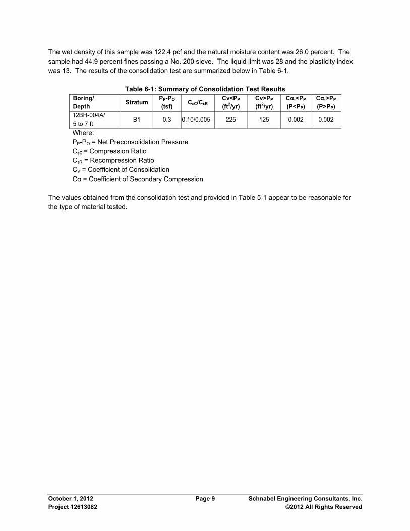
October 1, 2012 Page 9 Schnabel Engineering Consultants, Inc. Project 12613082 ©2012 All Rights Reserved
The wet density of this sample was 122.4 pcf and the natural moisture content was 26.0 percent. The sample had 44.9 percent fines passing a No. 200 sieve. The liquid limit was 28 and the plasticity index was 13. The results of the consolidation test are summarized below in Table 6-1.
Table 6-1: Summary of Consolidation Test Results Boring/ Depth Stratum PP-PO
(tsf) CεC/CεR
Cv<PP
(ft2/yr) Cv>PP
(ft2/yr) Cα,<PP
(P<PP) Cα,>PP
(P>PP) 12BH-004A/ 5 to 7 ft
B1 0.3 0.10/0.005 225 125 0.002 0.002
Where: PP-PO = Net Preconsolidation Pressure CεC = Compression Ratio CεR = Recompression Ratio CV = Coefficient of Consolidation Cα = Coefficient of Secondary Compression The values obtained from the consolidation test and provided in Table 5-1 appear to be reasonable for the type of material tested.

7.0 BOX CULVERTS, HECPS AND JUNCTION BOXES
7.1 Culvert and HECP Bedding Most of the test borings revealed very loose to loose density natural sands, and very soft consistency clays to a depth of about 30 ft below the ground surface. However, we consider the near-surface soils suitable for support of the proposed box culverts, pipes and junction boxes in part because these facilities are expect to all weigh less than the soils to be excavated for construction. Accordingly, settlements are expected to be limited to recompression of the soils that will be unloaded during excavation. Culverts, HECP and junction box subgrades should be evaluated in the field by a qualified Geotechnical Engineer. Culverts and HECPs should be installed in accordance with the guidelines presented in the VDOT Road and Bridge Specifications (2007). In accordance with VDOT Standard Specification 302.03(a)2.b, bedding material for culvert foundations, including foundations in soft materials, should consist of VDOT No. 25 or 26 aggregate except where standing or running water is present in the excavation. If standing or running water is present, the culvert bedding material should consist of VDOT No. 57 crushed stone below a 4-inch cap of VDOT No. 25 or 26 aggregate. Culvert bedding material should be uniformly compacted and should be at least 6 inches thick. Where soft, yielding, or otherwise unsuitable soils are observed at the culvert subgrade level, these materials should be undercut 12 inches and replaced with additional crushed stone. Soft clay of Stratum B2 is anticipated at or just below the quadruple 5’x3’ box culvert below Buckley Hall Road between about Stations 101+80 and 102+80. Because soils possessing petroleum odors encountered in Boring 12BH-002 could require excavation during construction of the culvert, we recommend chemical testing of the excavated soils if petroleum odors are observed during construction. The purpose of this testing is to support soil management considerations which could include off-site transportation and disposal.
7.2 Shallow Foundations Shallow mat and spread footing foundations are recommended for support of the proposed junction boxes and culvert wing walls, respectively. Foundations should be supported on suitable natural soils of Stratum B1. Shallow foundations can be designed for a net allowable soil bearing pressure not to exceed 1,000 psf. This bearing pressure provides a factor of safety of at least three against general shear failure. Foundations should be located at least 1.5 ft below final exterior grade for frost protection. Borings closest to the junction box and wing wall locations indicate sand of Stratum B1 at the subgrade elevations. However, soft alluvial clay of Stratum B2 could be encountered in excavations for these structures due to the potential variability of the alluvial soils between borings. If soft clay is encountered, it should be undercut to a depth of 12 inches and replaced with VDOT No. 57 crushed stone. The crushed stone should be compacted in place by at least two passes with suitable compaction equipment. Ground water is anticipated during excavation for foundations on this project. Accordingly, we recommend placing a 3-inch thick concrete mud mat to protect the subgrade. Alternatively, 6 inches of VDOT No. 57 crushed stone could be used to protect the subgrades where ground water is encountered.
October 1, 2012 Page 10 Schnabel Engineering Consultants, Inc. Project 12613082 ©2012 All Rights Reserved

Settlements of junction box and wing wall foundations supported on suitable natural soils and on VDOT No. 57 crushed stone are not expected to exceed about 1 inch. Angular distortion across junction box foundations is not expected to exceed an angular distortion of about 0.002 inches/inch. Concrete should be placed as soon as possible after excavation to limit the potential for moisture changes at the foundation level. Similarly, the junction box and wing wall foundations should be backfilled as soon as possible. Backfilling should be performed according to the recommendations included in Section 8 of this report. Wing wall footings can resist lateral loads by considering friction on the base of the footing. We recommend using an ultimate friction factor of 0.4 for concrete foundations poured on natural sand or crushed stone fill and a minimum factor of safety of 1.5 for evaluating sliding resistance. We have evaluated the Seismic Site Class for this project according to IBC Section 1613 (2009). We recommend Site Class E be used for seismic design on this project. This Site Class was evaluated based on Standard Penetration Test N-values, shear strength values from pocket penetrometer results, and extrapolation of the soil parameters to 100 feet.
7.3 Lateral Earth Pressures
Junction box walls and culvert wing walls are considered braced. Equivalent fluid pressure factors are presented in Table 7-1 for the respective backfill materials and, where applicable, surcharge loads using a rectangular earth pressure distribution.
Table 7-1: Recommended Design Parameters for Walls
Backfill Material Equivalent Fluid Pressure (pcf)
Surcharge Pressure Factor
VDOT #57 80 0.36 Soil Classified SC,SM per ASTM D-2487
90 0.46
The equivalent fluid earth pressure in Table 7-1 considers the ground water level at the top of the wall. Backfill compaction recommendations are provided in Section 8.
October 1, 2012 Page 11 Schnabel Engineering Consultants, Inc. Project 12613082 ©2012 All Rights Reserved

8.0 BACKFILL Soil backfill should consist of material classifying SC, SM, SP, SW, GC, GM, GP, or GW per ASTM D2487. Most of the non-organic, on-site soils are expected to meet this criterion. If off-site borrow soils are needed, they should also classify as SC, SM, SP, SW, GC, GM, GP or GW per ASTM D2487. Backfill should be placed in maximum eight-inch thick horizontal, loose lifts and should be compacted to at least 95 percent of maximum dry density per VTM-1 or ASTM D698, Standard Proctor. Successful reuse of the excavated, on-site soils as compacted backfill will depend on their natural moisture contents during excavation. Natural moisture content values of Strata A, B1 and B2 soils varied from about 5 percent below to about 30 percent above optimum for the soil types tested. Therefore, we anticipate scarifying and most of the on-site soils will be necessary to achieve the recommended compaction. The possibility of encountering groundwater is likely during construction. Accordingly, backfill materials may consist of open-graded crushed stone such as VDOT No. 57 crushed stone in order to facilitate compaction. The Contractor should place crushed stone backfill in maximum 12-inch thick lifts, and compact each lift using suitable vibratory equipment. Only light hand-operated equipment should be used to compact backfill against walls.
October 1, 2012 Page 12 Schnabel Engineering Consultants, Inc. Project 12613082 ©2012 All Rights Reserved

9.0 CONSTRUCTION CONSIDERATIONS
9.1 Foundations The contractor should exercise care during excavation so that as little disturbance as possible occurs at the foundation level. The contractor should carefully clean loose or soft soils from the bottom of the excavation before placing concrete. Foundation subgrades needing undercut should be concreted at the elevation of undercut or backfilled to the original design subgrade elevation with VDOT No. 57 crushed stone. A qualified Geotechnical Engineer should observe actual foundation subgrades during construction to evaluate whether subgrade soils meet the requirements as recommended in this report. The potential for variation of moisture content in foundation soils is probably greatest during construction. If the moisture content of foundation soils increases or decreases during construction, a moisture-related change in volume will likely occur as these soils return to their natural moisture content. Therefore, prompt placement of concrete, backfilling, and grading are very important for proper foundation performance.
9.2 Construction Dewatering We anticipate that groundwater will be encountered during excavation for the culverts, HECPs and junction boxes. Dewatering by pumping from trenches or sump pits at the bottom of the excavations could be effective in controlling ground water infiltration. Sumps should extend at least 2 ft below the base of the excavation. A well point system can also be used to dewater the excavation. Dewatering methods should be the responsibility of the Contractor.
9.3 Engineering Services During Construction The engineering recommendations provided in this report are based on the information obtained from the subsurface exploration and laboratory testing. However, conditions on the site may vary between the discrete locations observed at the time of our subsurface exploration. The nature and extent of variations between borings may not become evident until during construction. To account for this variability, we should provide professional observation and testing of actual subsurface conditions revealed during construction as an extension of our engineering services. These services will also help in evaluating the contractor's conformance with the plans and specifications.
October 1, 2012 Page 13 Schnabel Engineering Consultants, Inc. Project 12613082 ©2012 All Rights Reserved

10.0 GENERAL This report can be made available to prospective bidders for informational purposes. We recommend that the project specifications contain the following statement:
Schnabel has prepared this geotechnical engineering report for this project. This report is for informational purposes only and is not part of the contract documents. The opinions expressed represent the Geotechnical Engineer’s interpretation of the subsurface conditions, tests, and the results of analyses conducted. Should the data contained in this report not be adequate for the Contractor's purposes, the Contractor may make, before bidding, independent exploration, tests and analyses. This report may be examined by bidders at the office of the Owner, or copies may be obtained from the Owner at nominal charge.
The contract documents should include the boring and hand auger data provided in Appendix A.
October 1, 2012 Page 14 Schnabel Engineering Consultants, Inc. Project 12613082 ©2012 All Rights Reserved
October 1, 2012 Page 15 Schnabel Engineering Consultants, Inc. Project 12613082 ©2012 All Rights Reserved
11.0 LIMITATIONS
We based the analyses and recommendations submitted in this report on the information revealed by our exploration. We attempted to provide for normal contingencies, but the possibility remains that unexpected conditions may be encountered during construction.
We prepared this report to aid in the evaluation of this site and to assist in the design of the project. We intend it for use concerning this specific project. We based our recommendations on information on the site and proposed construction as described in this report. Substantial changes in loads, locations, or grades should be brought to our attention so we can modify our recommendations as needed.
We have endeavored to complete the services identified herein in a manner consistent with that level of care and skill ordinarily exercised by members of the profession currently practicing in the same locality and under similar conditions as this project. No other representation, express or implied, is included or intended, and no warranty or guarantee is included or intended in this report, or any other instrument of service.

FIGURES
Figure 1: Site Vicinity Map Figures 2A, 2B and 2C: Location Plans
October 1, 2012 Schnabel Engineering Consultants, Inc. Project 12613082 ©2012 All Rights Reserved

Main
St
Buckley Hall Rd
Cros
s Ct
Southwind Dr
Church St
UV14
UV14
Put In
Creek
UV14
³
Source:ESRI Imagery Service (http://goto.arcgisonline.com/maps/World_Imagery) ESRI MediaKit (2009&2010)Projection: NAD 1983 StatePlane Virginia South FIPS 4502 Feet
200 0 200100Feet
8/31/2
012
G:\20
12-S
EC-Jo
bs\12
6130
82_0
0_Rt
14_D
raina
ge\G
IS\Rt
14_V
ICIN
.mxd
Scale: 1:2,400
gnuy
da
ApproximateSite Location
FIGURE 1
SITEVICINITY
MAPPROJECT NO. 12613082.00
ROUTE 14 DRAINAGEIMPROVEMENTS
MATHEWS, VA
RuffRuff
RetzRetz
MoonMoon
LabanLaban
RedartRedart
MathewsMathews
HudginsHudgins
WilliamsWilliams
FitchettsFitchetts
TabernacleTabernacle
BeaverlettBeaverlett
ST14
ST198
_̂
SiteVicinity
ApproximateSite Location


October 1, 2012 Schnabel Engineering Consultants, Inc. Project 12613082 ©2012 All Rights Reserved
APPENDIX A
SUBSURFACE EXPLORATION DATA
Subsurface Exploration Procedures General Notes for Subsurface Exploration Logs VDOT Unified Soil Classification System Material and Sample Symbols List Boring Logs, 12BH-001 through 12BH-008, 12BH-012 and 12BH-013 Hand Auger Logs 12HA-001 and 12HA-002

SUBSURFACE EXPLORATION PROCEDURES Test Borings The borings are advanced by turning a hollow-stem auger with a center opening of 2¼ or 3¼ inches. A plug device blocks off the center opening while augers are advanced. Cuttings are brought to the surface by the auger flights. Sampling is performed through the center opening in the hollow stem auger, by standard methods, after removal of the plug. Water was not introduced into the boring using this procedure. Standard Penetration Test Results The numbers in the Sampling Data column of the boring logs represent Standard Penetration Test (SPT) results. Each number represents the blows needed to drive a 2-inch O.D., 1⅜-inch I.D. split-spoon sampler 6 inches, using a 140-pound hammer falling 30 inches. The sampler is typically driven a total of 18 or 24 inches. The first 6 inches are considered a seating interval. The total of the number of blows for the second and third 6-inch intervals is the SPT “N value.” The Standard Penetration Test is conducted according to ASTM D1586. Hand Augers Our personnel drilled the hand augers using a 3-inch O.D. auger. We visually classified the soils encountered according to the procedures outlined in this report. Dynamic Cone Penetrometer (DCP) measurements were obtained in the hand augers to provide a general indication of the relative density or consistency of the in-situ soils. DCP values are indicated on the hand auger logs. DCP tests were performed in general accordance with the paper titled “Dynamic Cone for Shallow In-Situ Penetration Testing”, ASTM Special Technical Publication No. 399, Sowers, G.F. and Hedges, C.S, 1966. Volatile Organic Vapor Screening The headspaces of soil samples collected during our subsurface exploration were screened for the presence of volatile organic vapors with a Photoionization Detector (PID). The PID provides an indication of the concentration of organic vapors in the headspace in parts per million (ppm). The PID detects a variety of organic vapors but does not detect the presence of methane. PID readings are presented in the sampling data column of the test boring log for Boring 12BH-002 where we observed petroleum odor in some of the samples. Water Observation Well A temporary water observation well was installed in Boring 12BH-013 by inserting a hand-slotted, 1¼-inch PVC pipe in this boring. The pipe was capped and the area surrounding the pipe was backfilled with cuttings from the boring. After about 26 hours, the groundwater level was measured and the pipe was removed and the hole backfilled.

GENERAL NOTES FOR SUBSURFACE EXPLORATION LOGS
1. Numbers in the Standard Penetration Test Hammer Blows column of the logs indicate blows required to drive a 2-inch O.D., 1⅜-inch I.D. sampling spoon 6 inches using a 140 pound hammer falling 30 inches. The Standard Penetration Test (SPT) N value is the number of blows required to drive the sampler 12 inches, after a 6-inch seating interval. The Standard Penetration Test is performed in general accordance with ASTM D1586.
2. Visual classification of soil is in accordance with terminology set forth in Chapter 3 of the Materials Manual of Instruction (MOI). The ASTM D2488 group symbols (e.g., CL) included in the Field Description of Strata column are based on visual observations. Some variation can be expected between samples visually classified and samples classified in the laboratory. Descriptions of materials tested in the laboratory were typically revised to indicate the material classification based on the results of the laboratory testing.
3. The values in the Pocket Penetrometer column represent pocket penetrometer readings. Pocket penetrometer readings provide an estimate of the unconfined compressive strength of fine-grained soils.
4. Water levels indicated on the logs are only estimates from available data and may vary with time, precipitation, porosity of the soil, site topography, and other factors.
5. The logs and related information depict subsurface conditions only at the specific locations and at the particular time when drilled or excavated. Soil conditions at other locations may differ from conditions occurring at these locations. Also, the passage of time may result in a change in the subsurface soil and water level conditions at the subsurface exploration location.
6. The stratification lines shown on the logs represent the approximate boundary between soil and rock types as obtained from the subsurface exploration. The transition lines appear on the logs as a finite boundary between two material types, but the transition between soil and rock materials may be finite or gradual. These transition lines are shown about half way between samples, as required by Chapter 3 of the Materials MOI, but some variation may also be expected vertically between samples taken.
7. The soil profile, water level observations and penetration resistances presented on these logs have been made with reasonable care and accuracy and must be considered only an approximate representation of subsurface conditions to be encountered at the particular location.
8. A list of material and sample symbols are included on the following pages.

UNIFIED SOIL CLASSIFICATION AND SYMBOL CHART LABORATORY CLASSIFICATION CRITERIA
PLASTICITY CHART
COARSE-GRAINED SOILS
FINE-GRAINED SOILS
(more than 50% of material is larger than No. 200 sieve size.)
(50% or more of material is smaller than No. 200 sieve size.)
Well-graded gravels, gravel-sandmixtures, little or no fines
greater than 4;
greater than 4;
between 1 and 3
between 1 and 3
=
=
=
=
Clean Gravels (Less than 5% fines)
C
C
C
C
D
D
D
D
D
D
D
D
D
D
u
u
c
c
60
60
30
30
x
x
10
10
10
10
60
60
Clean Sands (Less than 5% fines)
Above "A" line with P.I. between4 and 7 are borderline casesrequiring use of dual symbols
Limits plotting in shaded zonewith P.I. between 4 and 7 areborderline cases requiring useof dual symbols.
Determine percentages of sand and gravel from grain-size curve. Dependingon percentage of fines (fraction smaller than No. 200 sieve size),coarse-grained soils are classified as follows:
Less than 5 percentMore than 12 percent5 to 12 percent
GW, GP, SW, SPGM, GC, SM, SC
Borderline cases requiring dual symbols
Gravels with fines (More than 12% fines)
Sands with fines (More than 12% fines)
Well-graded sands, gravelly sands,little or no fines
Silty gravels, gravel-sand-silt mixturesAtterberg limits below "A"line or P.I. less than 4
Atterberg limits below "A"line or P.I. less than 4
Atterberg limits above "A"line with P.I. greater than 7
Atterberg limits above "A"line with P.I. greater than 7
Silty sands, sand-silt mixtures
Inorganic silts and very fine sands, rockflour, silty of clayey fine sands or clayeysilts with slight plasticity
Inorganic clays of low to mediumplasticity, gravelly clays, sandy clays,silty clays, lean clays
Inorganic silts, micaceous ordiatomaceous fine sandy or silty soils,elastic silts
Peat and other highly organic soils
Poorly-graded gravels, gravel-sandmixtures, little or no fines Not meeting all gradation requirements for GW
Not meeting all gradation requirements for GWPoorly graded sands, gravelly sands,little or no fines
Clayey gravels, gravel-sand-claymixtures
Clayey sands, sand-clay mixtures
Inorganic clays of high plasticity, fatclays
Organic silts and organic silty clays oflow plasticity
Organic clays of medium to highplasticity, organic silts
60
50
40
30
20
10
00 10 20 30 40 50
LIQUID LIMIT (LL) (%)
CL
CL+ML
CH
PL
AS
TIC
ITY
IND
EX
(P
I) (
%)
60 70 80 90 100
GW GW
GRAVELS
SANDS
SILTSAND
CLAYS
SILTSAND
CLAYS
HIGHLYORGANIC
SOILS
More than 50%of coarse
fraction largerthan No. 4sieve size
50% or moreof coarse
fraction smallerthan No. 4sieve size
Liquid limitless than
50%
Liquid limit50%
or greater
SW SW
GM GM
SM SM
ML
MH
PT
GP GP
SPSP
GC GC
SC SC
CL
CH
OL
OH
MH&OH
A LINE:PI = 0.73(LL-20)
ML&OL
UNIFIED SOILCLASSIFICATION SYSTEM

CH -
Fat Clay
CL -
Lean Clay
FL -Fill
GC - Clayey
Gravel
GM - Silty
Gravel
GP - Poorly-
graded Gravel
GW - Well-
Graded Gravel
ML - Silt
SC -
Clayey Sand
CL-ML
GC-GM
SW - Well-
Graded Sand
SM - Silty
Sand
SP - Poorly-
Graded Sand
Pavement/Soils
ASPH-
ASPHALT PVT
CONC-
CONCRETE PVT
GP-GC
GP-GM
GW-GC
GW-GM
SP-SC
SP-SM
SW-SC
SW-SM
AND -
Andesite
BST -
Basalt
CAV -
Cavity
DBS -
Diabase
DRT -
Diorite
GBR -
Gabbro
GGE -
Gouge SPT
Core
Grab
No
Recovery
Other
SLS -
Siltstone
SST-SHL -
Interbedded
Sandstone/Shale
MYL -
Mylonite
PHY -
Phyllite
RHY -
Rhyolite
SCH -
Schist
SedimentaryRocks
MetamorphicRocks
SamplingIgneousRocks
MATERIAL AND SAMPLESYMBOLS LIST
GNS -
Gneiss
Auger
Undisturbed
CGL -
Conglomorate
COL -
Coal
GWK -
Graywacke
LST -
Limestone
SHL -
Shale
SST -
Sandstone
CLST - Cherty
Limestone
SLT -
Slate
GRD -
Granodiorite
GRN
Granite
POR -
Porphyry
SE -
Shell Bed
UCY -
Underclay
SST-SLS -
Interbedded
Sandstone/Siltstone
MH -
Elastic Silt
MH/CH
MH/ML
MH/SM
ML/CL
ML/GM
ML/SM
GM/GP
GM/ML
GM/SM
HWR
Highly Weathered
Rock
MST
Mudstone
BRC -
Breccia
Misc.
SHDS
Shaly Dolostone
CHK
Chalk
SHLS-Shaly
Limestone
MSH
Silty Shale
Page 1of 2
SSHL
Sandy Shale
Vane

Pavement/SoilsSedimentary
RocksMetamorphic
RocksSampling
IgneousRocks
MATERIAL AND SAMPLESYMBOLS LIST
TOPS-
TOPSOIL CH/CL CH/MH CH/SC
CL/ML CL/SC CL/CHCRA
Crushed Aggregate
GC/SC
GP/GW
GP/SPGW/GP ML/MH
OH
Organic
OH/OL
OL
OrganicOL/OHPT
Peat
SC/CH
SC/CL
SC/GC SC-SM
BLD-Boulder
Bed
CHT
Charnocktite
DLS
Dolostone
LST-DLS-
Interbedded
Limestone/Dolostone
MSLS
Metasiltstone
MSST
Metasandstone
QZT -
Quartzite
MBST
Metabasalt
SPS
Soapstone
MBL
Marble
Page 2 of 2
SP/SW SM/GM SM/MH
SM/ML SM/SC SP/GP SW/SP
CHRT

0.25
13.5
22.1
20.3
30.5
37.9
32.9
35.2
53.0
34.2
24.5
0.0 / 5.02-INCHES FOREST LITTER, ROOTMAT ANDTOPSOIL TOPS0.2 / 4.8Gray, fine to medium clayey SAND, contains roots,loose, moist [B1] [ALLUVIUM] SC
4.0 / 1.0Gray, fine to coarse silty SAND, loose, moist SM
SAME, light gray, very loose, wet below 7 ft
14.5 / -9.5Gray, fine to medium poorly graded SAND with silt,medium dense, wet SP-SM
SAME, loose below 20 ft
22.0 / -17.0Gray, fat CLAY, contains shell fragments, soft, wet[C1] [YORKTOWN FORMATION] CH
24.75 / -19.75Dark gray, fine to medium clayey SAND, loose, wetSC
Bottom of Boring at 30 ft.
67
47
73
93
100
67
53
87
100
PAGE 1 OF 1
12BH-001
12BH-001
FIELD DESCRIPTION OF STRATA
GROUND WATER
PAGE 1 OF 1OFFSET: 15 FT LTLONGITUDE: 76.320853° WCOORD. DATUM: NAD 83
REMARKS: Rig Type: CME-45B (Truck).
Copyright 2012, Commonwealth of Virginia
SP
T_L
OG
AB
:126
130
82 V
DO
T L
OG
S.G
PJ:
8.30
.003
:012
512:
9/2
7/12
PK
T. P
EN
ET
RO
ME
TE
R (
tsf)
LAB DATA
MO
IST
UR
E C
ON
TE
NT
(%
)
PLA
ST
ICIT
Y IN
DE
X
PILL
LIQ
UID
LIM
IT
FIN
ES
CO
NT
EN
T -
#200
(%
)
SO
IL R
EC
OV
ER
Y (
%)
CO
RE
RE
CO
VE
RY
(%
)
FIRST ENCOUNTERED AT 5.0 ft DEPTH
DIP °
R O C K
SA
MP
LE L
EG
EN
D
S O I L
PROJECT #:LOCATION:STRUCTURE:
ELE
VA
TIO
N (
ft)
0
-5
-10
-15
-20
-25
DE
PT
H (
ft)
SA
MP
LE IN
TE
RV
AL
RO
CK
QU
ALI
TY
DE
SIG
NA
TIO
N
ST
AN
DA
RD
PE
NE
TR
AT
ION
TE
ST
HA
MM
ER
BLO
WS
FIELD DATA
ST
RA
TA
LE
GE
ND
JOIN
TS
ST
RA
TA
2
4
6
8
10
12
14
16
18
20
22
24
26
28
30
STATION: 101+37LATITUDE: 37.437483° NSURFACE ELEVATION: 5.0 ft
12613082Rt 14 Drainage ImprovementsCULVERT
Date(s) Drilled: 08/23/2012 - 08/23/2012Drilling Method(s): 2-1/4" I.D. Hollow Stem AugerSPT Method: Safety Hammer (140 lb)Other Test(s): Not ApplicableDriller: Ayers & Ayers, Inc.Logger: J. Ruffin
4
2
3
1
WOH
2
4
WOH
1
3
3
2
1
WOH
6
2
1
4
4
1
3
0
WOH
8
1
2
3
1.52
3.54
5.5
7
8.59
10.5
14
15.5
19
20.5
24
2525.5
28.5
30

0.25
0.25
11.1
7.2
29.3
59.2
36.3
32.5
31.4
63.9
36.2
0.0 / 5.752.5-INCHES ASPHALT, No base ASPH0.2 / 5.55Orange brown, fine to medium silty sand FILL, containsgravel, medium dense, moist [A] [FILL] FL
4.0 / 1.75Dark gray, fine to medium clayey SAND, very loose, moist[B1] [ALLUVIUM] SC
6.5 / -0.75Dark brown, fat CLAY, contains organic matter, very soft,wet [B2] CH8.5 / -2.75Light gray, fine to medium clayey SAND, contains organicmatter, soft, wet [B1] SCSAME, soft below 10 ft
17.0 / -11.25Gray, fine to medium poorly graded SAND with silt, loose,wet SP-SM
23.0 / -17.25Gray, fat CLAY, contains mica, very soft, wet [C1][YORKTOWN FORMATION] CH
29.5 / -23.75Gray, fat CLAY with sand, firm, wet CHBottom of Boring at 30 ft.
87
47
40
53
80
87
87
100
100
PAGE 1 OF 1
12BH-002
12BH-002
FIELD DESCRIPTION OF STRATA
GROUND WATER
PAGE 1 OF 1OFFSET: 15 FT LTLONGITUDE: 76.320943° WCOORD. DATUM: NAD 83
REMARKS: Rig Type: CME-45B (Truck).Offset 30 ft north and 17 ft east.PID@ 4-5.5'=25 ppm
Copyright 2012, Commonwealth of Virginia
SP
T_L
OG
A:1
261
3082
VD
OT
LO
GS
.GP
J:8.
30.0
03:0
1251
2:9/
27/
12
PK
T. P
EN
ET
RO
ME
TE
R (
tsf)
LAB DATA
MO
IST
UR
E C
ON
TE
NT
(%
)
PLA
ST
ICIT
Y IN
DE
X
PILL
LIQ
UID
LIM
IT
SO
IL R
EC
OV
ER
Y (
%)
CO
RE
RE
CO
VE
RY
(%
)
FIRST ENCOUNTERED AT 7.0 ft DEPTH
DIP °
R O C K
SA
MP
LE L
EG
EN
D
S O I L
PROJECT #:LOCATION:STRUCTURE:
ELE
VA
TIO
N (
ft)
5
0
-5
-10
-15
-20
DE
PT
H (
ft)
SA
MP
LE IN
TE
RV
AL
RO
CK
QU
ALI
TY
DE
SIG
NA
TIO
N
ST
AN
DA
RD
PE
NE
TR
AT
ION
TE
ST
HA
MM
ER
BLO
WS
FIELD DATA
ST
RA
TA
LE
GE
ND
JOIN
TS
ST
RA
TA
2
4
6
8
10
12
14
16
18
20
22
24
26
28
30
STATION: 102+10LATITUDE: 37.437308° NSURFACE ELEVATION: 5.75 ft
12613082Rt 14 Drainage ImprovementsCULVERT
Date(s) Drilled: 08/23/2012 - 08/23/2012Drilling Method(s): 2-1/4" I.D. Hollow Stem AugerSPT Method: Safety Hammer (140 lb)Other Test(s): Not ApplicableDriller: Ayers & Ayers, Inc.Logger: J. Ruffin
5
8
2
WOH
WOH
1
3
1
1
7
5
1
WOH
1
2
3
0
1
6
3
2
WOH
1
2
2
1
5
0.5
2
3.54
5.5
7
8.59
10.5
14
15.5
19
20.5
24
2525.5
28.529
30

0.5
0.25
11.4
13.8
21.4
30.2
37.3
31.3
25.7
66.8
34.4
0.0 / 6.51-INCH ASPHALT, No base ASPH0.1 / 6.4Orange gray, fine to coarse clayey sand FILL, loose, moist[B1] [ALLUVIUM] FL0.5 / 6.0Dark gray, fine to medium silty SAND, loose, moist SM4.0 / 2.5Light gray, fine to medium clayey SAND, loose, wet SC
SAME, very loose below 8 ft
13.0 / -6.5Light gray, fine to medium clayey SAND, contains shellfragments, very loose, moist [C2] [YORKTOWNFORMATION] SC
SAME, loose below 20 ft
22.0 / -15.5Light gray, fat CLAY, very soft, moist [C1] CH
SAME, soft below 29 ft
Bottom of Boring at 30 ft.
67
60
67
87
93
93
100
87
PAGE 1 OF 1
12BH-003
12BH-003
FIELD DESCRIPTION OF STRATA
GROUND WATER
PAGE 1 OF 1OFFSET: 23 FT RTLONGITUDE: 76.321232° WCOORD. DATUM: NAD 83
REMARKS: Rig Type: CME-45B (Truck).
Copyright 2012, Commonwealth of Virginia
SP
T_L
OG
A:1
261
3082
VD
OT
LO
GS
.GP
J:8.
30.0
03:0
1251
2:9/
27/
12
PK
T. P
EN
ET
RO
ME
TE
R (
tsf)
LAB DATA
MO
IST
UR
E C
ON
TE
NT
(%
)
PLA
ST
ICIT
Y IN
DE
X
PILL
LIQ
UID
LIM
IT
SO
IL R
EC
OV
ER
Y (
%)
CO
RE
RE
CO
VE
RY
(%
)
FIRST ENCOUNTERED AT 5.0 ft DEPTH
DIP °
R O C K
SA
MP
LE L
EG
EN
D
S O I L
PROJECT #:LOCATION:STRUCTURE:
ELE
VA
TIO
N (
ft)
5
0
-5
-10
-15
-20
DE
PT
H (
ft)
SA
MP
LE IN
TE
RV
AL
RO
CK
QU
ALI
TY
DE
SIG
NA
TIO
N
ST
AN
DA
RD
PE
NE
TR
AT
ION
TE
ST
HA
MM
ER
BLO
WS
FIELD DATA
ST
RA
TA
LE
GE
ND
JOIN
TS
ST
RA
TA
2
4
6
8
10
12
14
16
18
20
22
24
26
28
30
STATION: 103+33LATITUDE: 37.437040° NSURFACE ELEVATION: 6.5 ft
12613082Rt 14 Drainage ImprovementsCULVERT
Date(s) Drilled: 08/23/2012 - 08/23/2012Drilling Method(s): 2-1/4" I.D. Hollow Stem AugerSPT Method: Safety Hammer (140 lb)Other Test(s): Not ApplicableDriller: Ayers & Ayers, Inc.Logger: J. Ruffin
7
4
4
1
1
1
5
WOH
2
5
6
2
1
1
1
3
WOH
1
3
3
3
0
1
2
3
1
2
0.5
2
3.54
5.5
7
8.59
10.5
14
15.5
19
20.5
24
2525.5
28.529
30

0.25
0.25
9.2
18.1
24.0
26.2
28.2
28.4
28.2
58.9
58.0
26 10 38.4
0.0 / 5.03-INCHES FOREST LITTER, ROOTMAT ANDTOPSOIL TOPS0.25 / 4.75Orange brown, fine to coarse clayey sand FILL,medium dense, moist FL0.75 / 4.25Gray, fine to coarse clayey SAND, very loose, moist[B1] [ALLUVIUM] SC
SAME, light gray, wet below 6.5 ft
12.0 / -7.0Gray, fine to medium poorly graded SAND with silt,loose, wet SP-SM
SAME, very loose below 21 ft
22.0 / -17.0Gray, fat CLAY, contains shell fragments, soft, wet[C1] [YORKTOWN FORMATION] CH
93
40
53
80
87
87
87
80
73
PAGE 1 OF 2
12BH-004
12BH-004
FIELD DESCRIPTION OF STRATA
GROUND WATER
PAGE 1 OF 2OFFSET: 40 FT RTLONGITUDE: 76.321433° WCOORD. DATUM: NAD 83
REMARKS: Rig Type: CME-45B (Truck).Offset 30 feet west of creek.
Copyright 2012, Commonwealth of Virginia
SP
T_L
OG
AB
:126
130
82 V
DO
T L
OG
S.G
PJ:
8.30
.003
:012
512:
9/2
7/12
PK
T. P
EN
ET
RO
ME
TE
R (
tsf)
LAB DATA
MO
IST
UR
E C
ON
TE
NT
(%
)
PLA
ST
ICIT
Y IN
DE
X
PILL
LIQ
UID
LIM
IT
FIN
ES
CO
NT
EN
T -
#200
(%
)
SO
IL R
EC
OV
ER
Y (
%)
CO
RE
RE
CO
VE
RY
(%
)
FIRST ENCOUNTERED AT 7.0 ft DEPTH
DIP °
R O C K
SA
MP
LE L
EG
EN
D
S O I L
PROJECT #:LOCATION:STRUCTURE:
ELE
VA
TIO
N (
ft)
0
-5
-10
-15
-20
-25
DE
PT
H (
ft)
SA
MP
LE IN
TE
RV
AL
RO
CK
QU
ALI
TY
DE
SIG
NA
TIO
N
ST
AN
DA
RD
PE
NE
TR
AT
ION
TE
ST
HA
MM
ER
BLO
WS
FIELD DATA
ST
RA
TA
LE
GE
ND
JOIN
TS
ST
RA
TA
2
4
6
8
10
12
14
16
18
20
22
24
26
28
30
32
STATION: 104+44LATITUDE: 37.436787° NSURFACE ELEVATION: 5.0 ft
12613082Rt 14 Drainage ImprovementsCULVERT
Date(s) Drilled: 08/23/2012 - 08/23/2012Drilling Method(s): 2-1/4" I.D. Hollow Stem AugerSPT Method: Safety Hammer (140 lb)Other Test(s): Not ApplicableDriller: Ayers & Ayers, Inc.Logger: J. Ruffin
3
2
1
1
1
1
2
1
2
6
1
1
1
1
2
1
1
1
5
1
1
1
0
3
0
1
1
1.52
3.54
5.5
7
8.59
10.5
14
15.5
19
20.5
24
2525.5
29
30.5

0.5
0.5
0.75
62.1
69.7
58.6
32.5 / -27.5Gray, fat CLAY, contains shell fragments, soft, wet[C1] [YORKTOWN FORMATION] CH
Bottom of Boring at 45 ft.
100
87
PAGE 2 OF 2
12BH-004
12BH-004
FIELD DESCRIPTION OF STRATA
GROUND WATER
PAGE 2 OF 2OFFSET: 40 FT RTLONGITUDE: 76.321433° WCOORD. DATUM: NAD 83
REMARKS: Rig Type: CME-45B (Truck).Offset 30 feet west of creek.
Copyright 2012, Commonwealth of Virginia
SP
T_L
OG
AB
:126
130
82 V
DO
T L
OG
S.G
PJ:
8.30
.003
:012
512:
9/2
7/12
PK
T. P
EN
ET
RO
ME
TE
R (
tsf)
LAB DATA
MO
IST
UR
E C
ON
TE
NT
(%
)
PLA
ST
ICIT
Y IN
DE
X
PILL
LIQ
UID
LIM
IT
FIN
ES
CO
NT
EN
T -
#200
(%
)
SO
IL R
EC
OV
ER
Y (
%)
CO
RE
RE
CO
VE
RY
(%
)
FIRST ENCOUNTERED AT 7.0 ft DEPTH
DIP °
R O C K
SA
MP
LE L
EG
EN
D
S O I L
PROJECT #:LOCATION:STRUCTURE:
ELE
VA
TIO
N (
ft)
-30
-35
-40
DE
PT
H (
ft)
SA
MP
LE IN
TE
RV
AL
RO
CK
QU
ALI
TY
DE
SIG
NA
TIO
N
ST
AN
DA
RD
PE
NE
TR
AT
ION
TE
ST
HA
MM
ER
BLO
WS
FIELD DATA
ST
RA
TA
LE
GE
ND
JOIN
TS
ST
RA
TA
34
36
38
40
42
44
STATION: 104+44LATITUDE: 37.436787° NSURFACE ELEVATION: 5.0 ft
12613082Rt 14 Drainage ImprovementsCULVERT
Date(s) Drilled: 08/23/2012 - 08/23/2012Drilling Method(s): 2-1/4" I.D. Hollow Stem AugerSPT Method: Safety Hammer (140 lb)Other Test(s): Not ApplicableDriller: Ayers & Ayers, Inc.Logger: J. Ruffin
1
1
1
2
2
2
1
1
2
34
35.5
39
4040.5
43.544
45
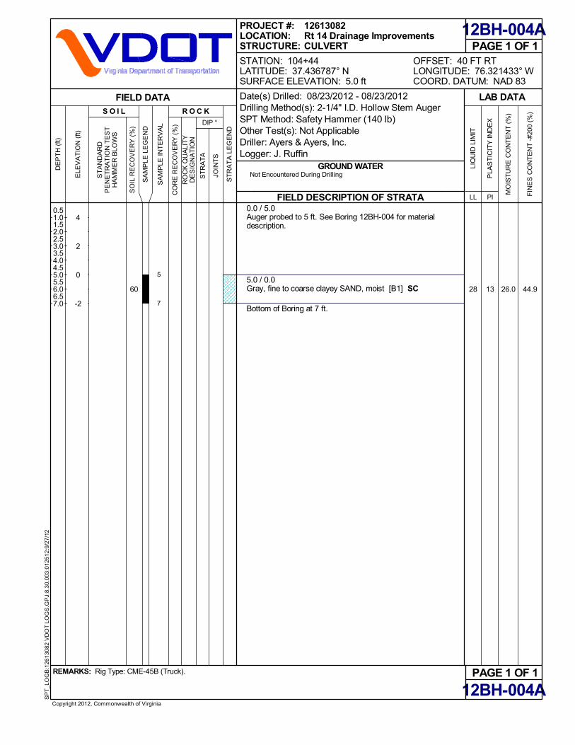
26.028 13 44.9
0.0 / 5.0Auger probed to 5 ft. See Boring 12BH-004 for materialdescription.
5.0 / 0.0Gray, fine to coarse clayey SAND, moist [B1] SC
Bottom of Boring at 7 ft.
60
PAGE 1 OF 1
12BH-004A
12BH-004A
FIELD DESCRIPTION OF STRATA
GROUND WATER
PAGE 1 OF 1OFFSET: 40 FT RTLONGITUDE: 76.321433° WCOORD. DATUM: NAD 83
REMARKS: Rig Type: CME-45B (Truck).
Copyright 2012, Commonwealth of Virginia
SP
T_L
OG
B:1
261
3082
VD
OT
LO
GS
.GP
J:8.
30.0
03:0
1251
2:9/
27/
12
LAB DATA
MO
IST
UR
E C
ON
TE
NT
(%
)
PLA
ST
ICIT
Y IN
DE
X
PILL
LIQ
UID
LIM
IT
FIN
ES
CO
NT
EN
T -
#200
(%
)
SO
IL R
EC
OV
ER
Y (
%)
CO
RE
RE
CO
VE
RY
(%
)Not Encountered During Drilling
DIP °
R O C K
SA
MP
LE L
EG
EN
D
S O I L
PROJECT #:LOCATION:STRUCTURE:
ELE
VA
TIO
N (
ft)
4
2
0
-2
DE
PT
H (
ft)
SA
MP
LE IN
TE
RV
AL
RO
CK
QU
ALI
TY
DE
SIG
NA
TIO
N
ST
AN
DA
RD
PE
NE
TR
AT
ION
TE
ST
HA
MM
ER
BLO
WS
FIELD DATA
ST
RA
TA
LE
GE
ND
JOIN
TS
ST
RA
TA
0.51.01.52.02.53.03.54.04.55.05.56.06.57.0
STATION: 104+44LATITUDE: 37.436787° NSURFACE ELEVATION: 5.0 ft
12613082Rt 14 Drainage ImprovementsCULVERT
Date(s) Drilled: 08/23/2012 - 08/23/2012Drilling Method(s): 2-1/4" I.D. Hollow Stem AugerSPT Method: Safety Hammer (140 lb)Other Test(s): Not ApplicableDriller: Ayers & Ayers, Inc.Logger: J. Ruffin
5
7

0.25
0.25
0.5
16.0
53.9
33.4
40.2
31.9
29.0
32.0
65.2
70.2
43 16 34.5
0.0 / 2.62-INCHES FOREST LITTER, ROOTMAT ANDTOPSOIL TOPS0.2 / 2.4Brown, fine to medium clayey sand FILL, containsroots, loose, moist [A] [FILL] FL2.0 / 0.6Gray, sandy fat CLAY, contains organic matter, soft,moist [B2] [ALLUVIUM] CH4.0 / -1.4Dark gray, fine to coarse clayey SAND, very loose,moist [B1] SCSAME, dark gray below 7 ft
8.5 / -5.9Dark gray, fine to medium silty SAND, loose, moistSM
12.0 / -9.4Green gray, fine to medium poorly graded SAND withsilt, medium dense, wet SP-SM
17.0 / -14.4Gray, fine to medium clayey SAND, very loose, wetSC
22.0 / -19.4Gray, fat CLAY, contains shell fragments, soft, moist[C1] [YORKTOWN FORMATION] CH
Bottom of Boring at 30 ft.
67
93
60
60
73
67
73
100
PAGE 1 OF 1
12BH-005
12BH-005
FIELD DESCRIPTION OF STRATA
GROUND WATER
PAGE 1 OF 1OFFSET: 15 FT RTLONGITUDE: 76.322819° WCOORD. DATUM: NAD 83
REMARKS: Rig Type: CME-45B (Truck).Offset 9 ft to the west of creek.
Copyright 2012, Commonwealth of Virginia
SP
T_L
OG
AB
:126
130
82 V
DO
T L
OG
S.G
PJ:
8.30
.003
:012
512:
9/2
7/12
PK
T. P
EN
ET
RO
ME
TE
R (
tsf)
LAB DATA
MO
IST
UR
E C
ON
TE
NT
(%
)
PLA
ST
ICIT
Y IN
DE
X
PILL
LIQ
UID
LIM
IT
FIN
ES
CO
NT
EN
T -
#200
(%
)
SO
IL R
EC
OV
ER
Y (
%)
CO
RE
RE
CO
VE
RY
(%
)
FIRST ENCOUNTERED AT 9.0 ft DEPTH
DIP °
R O C K
SA
MP
LE L
EG
EN
D
S O I L
PROJECT #:LOCATION:STRUCTURE:
ELE
VA
TIO
N (
ft)
0
-5
-10
-15
-20
-25
DE
PT
H (
ft)
SA
MP
LE IN
TE
RV
AL
RO
CK
QU
ALI
TY
DE
SIG
NA
TIO
N
ST
AN
DA
RD
PE
NE
TR
AT
ION
TE
ST
HA
MM
ER
BLO
WS
FIELD DATA
ST
RA
TA
LE
GE
ND
JOIN
TS
ST
RA
TA
2
4
6
8
10
12
14
16
18
20
22
24
26
28
30
STATION: 302+34LATITUDE: 37.433965° NSURFACE ELEVATION: 2.6 ft
12613082Rt 14 Drainage ImprovementsCULVERT
Date(s) Drilled: 08/22/2012 - 08/22/2012Drilling Method(s): 2-1/4" I.D. Hollow Stem AugerSPT Method: Safety Hammer (140 lb)Other Test(s): Not ApplicableDriller: Ayers & Ayers, Inc.Logger: J. Ruffin
2
1
1
1
1
4
1
1
1
2
1
1
1
1
10
1
1
1
2
1
2
1
4
11
1
1
1
1.52
33.54
5.5
7
8.59
10.5
14
15.5
19
20.5
24
2525.5
28.529
30
0.5
0.5
7.1
10.4
11.2
23.4
38.2
24.9
27.6
68.4
68.7
0.0 / 2.53-INCHES FOREST LITTER, ROOTMAT AND TOPSOILTOPS0.25 / 2.25Brown, fine to coarse clayey sand FILL, loose, moist FLSAME, orange brown, very loose below 2 ft
SAME, dark gray brown, wet below 4 ft
6.5 / -4.0Dark gray, fine to medium silty SAND, loose, wet [B1][ALLUVIUM] SM
8.5 / -6.0Light brown gray, fine to medium clayey SAND, very loose,wet SC
12.0 / -9.5Gray, fine to medium poorly graded SAND with silt, dense,wet SP-SM
18.0 / -15.5Gray, fine to medium clayey SAND, very loose, wet SC
22.0 / -19.5Gray, fat CLAY, soft, moist [C1] [YORKTOWNFORMATION] CH
Bottom of Boring at 30 ft.
53
47
67
33
87
100
87
80
87
PAGE 1 OF 1
12BH-006
12BH-006
FIELD DESCRIPTION OF STRATA
GROUND WATER
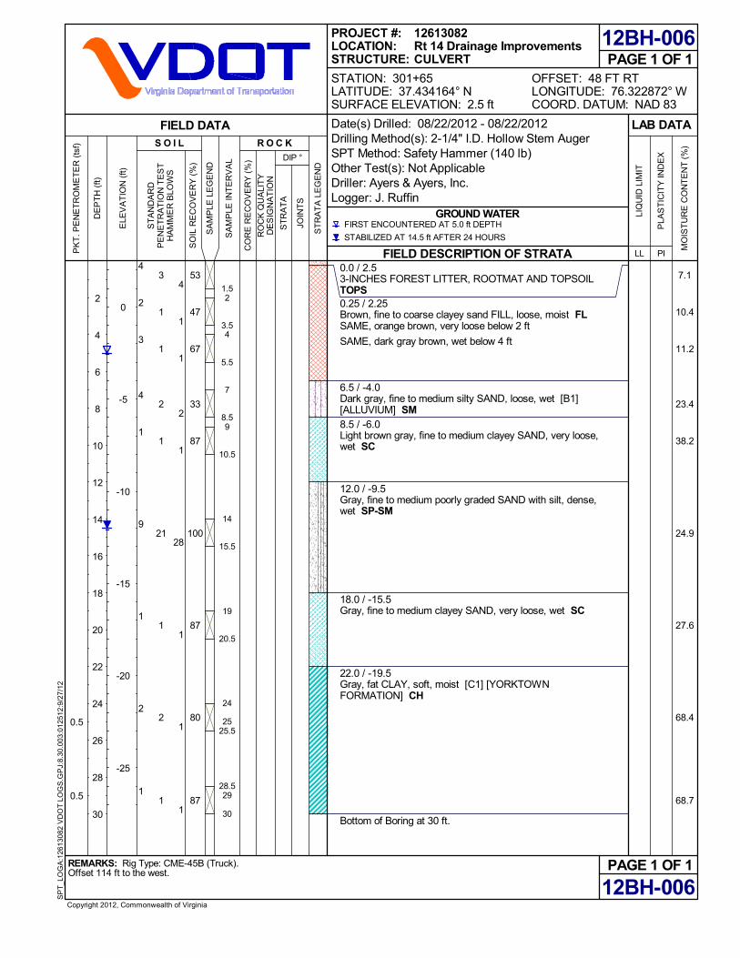
PAGE 1 OF 1OFFSET: 48 FT RTLONGITUDE: 76.322872° WCOORD. DATUM: NAD 83
REMARKS: Rig Type: CME-45B (Truck).Offset 114 ft to the west.
Copyright 2012, Commonwealth of Virginia
SP
T_L
OG
A:1
261
3082
VD
OT
LO
GS
.GP
J:8.
30.0
03:0
1251
2:9/
27/
12
PK
T. P
EN
ET
RO
ME
TE
R (
tsf)
LAB DATA
MO
IST
UR
E C
ON
TE
NT
(%
)
PLA
ST
ICIT
Y IN
DE
X
PILL
LIQ
UID
LIM
IT
SO
IL R
EC
OV
ER
Y (
%)
CO
RE
RE
CO
VE
RY
(%
)
FIRST ENCOUNTERED AT 5.0 ft DEPTH
STABILIZED AT 14.5 ft AFTER 24 HOURS
DIP °
R O C K
SA
MP
LE L
EG
EN
D
S O I L
PROJECT #:LOCATION:STRUCTURE:
ELE
VA
TIO
N (
ft)
0
-5
-10
-15
-20
-25
DE
PT
H (
ft)
SA
MP
LE IN
TE
RV
AL
RO
CK
QU
ALI
TY
DE
SIG
NA
TIO
N
ST
AN
DA
RD
PE
NE
TR
AT
ION
TE
ST
HA
MM
ER
BLO
WS
FIELD DATA
ST
RA
TA
LE
GE
ND
JOIN
TS
ST
RA
TA
2
4
6
8
10
12
14
16
18
20
22
24
26
28
30
STATION: 301+65LATITUDE: 37.434164° NSURFACE ELEVATION: 2.5 ft
12613082Rt 14 Drainage ImprovementsCULVERT
Date(s) Drilled: 08/22/2012 - 08/22/2012Drilling Method(s): 2-1/4" I.D. Hollow Stem AugerSPT Method: Safety Hammer (140 lb)Other Test(s): Not ApplicableDriller: Ayers & Ayers, Inc.Logger: J. Ruffin
4
2
3
4
1
9
1
2
1
3
1
1
2
1
21
1
2
1
4
1
1
2
1
28
1
1
1
1.52
3.54
5.5
7
8.59
10.5
14
15.5
19
20.5
24
2525.5
28.529
30

0.5
16.2
34.6
32.6
35.1
24.1
36.0
56.3
62.1
0.0 / 4.02-INCHES ASPHALT ASPH0.13 / 3.873-INCHES DENSE GRADED AGGREGATE BASE CRA0.4 / 3.6Orange brown, fine to coarse silty sand with gravel FILL,dense, moist [A] [FILL] FL2.0 / 2.0Dark gray, fine to medium silty SAND, medium dense, moist[B1] [ALLUVIUM] SM4.0 / 0.0Green gray, fine to medium clayey SAND, very loose, moistSCSAME, wet below 7 ft
13.0 / -9.0Light gray, fine to medium poorly graded SAND with silt,medium dense, wet SP-SM
17.0 / -13.0Dark gray, fine to medium clayey SAND, very loose, wet SC
22.5 / -18.5Gray, fat CLAY, contains shell fragments, soft, moist [C1][YORKTOWN FORMATION] CH
Bottom of Boring at 30 ft.
80
53
67
100
100
93
100
87
87
PAGE 1 OF 1
12BH-007
12BH-007
FIELD DESCRIPTION OF STRATA
GROUND WATER
PAGE 1 OF 1OFFSET: 5 FT RTLONGITUDE: 76.320751° WCOORD. DATUM: NAD 83
REMARKS: Rig Type: CME-45B (Truck).Offset 8.5 ft to the North, BHP
Copyright 2012, Commonwealth of Virginia
SP
T_L
OG
A:1
261
3082
VD
OT
LO
GS
.GP
J:8.
30.0
03:0
1251
2:9/
27/
12
PK
T. P
EN
ET
RO
ME
TE
R (
tsf)
LAB DATA
MO
IST
UR
E C
ON
TE
NT
(%
)
PLA
ST
ICIT
Y IN
DE
X
PILL
LIQ
UID
LIM
IT
SO
IL R
EC
OV
ER
Y (
%)
CO
RE
RE
CO
VE
RY
(%
)
FIRST ENCOUNTERED AT 7.0 ft DEPTH
DIP °
R O C K
SA
MP
LE L
EG
EN
D
S O I L
PROJECT #:LOCATION:STRUCTURE:
ELE
VA
TIO
N (
ft)
0
-5
-10
-15
-20
-25
DE
PT
H (
ft)
SA
MP
LE IN
TE
RV
AL
RO
CK
QU
ALI
TY
DE
SIG
NA
TIO
N
ST
AN
DA
RD
PE
NE
TR
AT
ION
TE
ST
HA
MM
ER
BLO
WS
FIELD DATA
ST
RA
TA
LE
GE
ND
JOIN
TS
ST
RA
TA
2
4
6
8
10
12
14
16
18
20
22
24
26
28
30
STATION: 201+15LATITUDE: 37.434463° NSURFACE ELEVATION: 4.0 ft
12613082Rt 14 Drainage ImprovementsCULVERT
Date(s) Drilled: 08/22/2012 - 08/22/2012Drilling Method(s): 2-1/4" I.D. Hollow Stem AugerSPT Method: Safety Hammer (140 lb)Other Test(s): Not ApplicableDriller: Ayers & Ayers, Inc.Logger: J. Ruffin
44
5
1
1
WOH
16
1
1
1
22
6
2
1
WOH
16
1
1
1
11
5
1
0
WOH
13
2
1
2
0.5
2
3.54
5.5
7
8.59
10.5
14
15.5
19
20.5
24
2525.5
28.5
30

0.5
0.5
22.4
24.4
37.6
30.2
27.2
28.2
39.4
65.2
66.5
25 4 25.5
0.0 / 4.01-INCH ASPHALT, no base ASPH0.1 / 3.9Orange brown, fine to coarse clayey sand FILL, veryloose, moist [A] [FILL] FL2.0 / 2.0Brown and gray, fine to coarse silty, clayey SAND,very loose, moist [B1] [ALLUVIUM] SC-SM
SAME, wet below 7 ft
13.0 / -9.0Light gray, fine to coarse poorly graded SAND withsilt, medium dense, wet SP-SM
17.0 / -13.0Gray, fine to medium clayey SAND, very loose, wetSC
23.0 / -19.0Gray, fat CLAY, contains shell fragments, soft, moist[C1] [YORKTOWN FORMATION] CH
Bottom of Boring at 30 ft.
87
47
7
100
100
87
87
87
PAGE 1 OF 1
12BH-008
12BH-008
FIELD DESCRIPTION OF STRATA
GROUND WATER
PAGE 1 OF 1OFFSET: 1 FT LTLONGITUDE: 76.321029° WCOORD. DATUM: NAD 83
REMARKS: Rig Type: CME-45B (Truck).
Copyright 2012, Commonwealth of Virginia
SP
T_L
OG
AB
:126
130
82 V
DO
T L
OG
S.G
PJ:
8.30
.003
:012
512:
9/2
7/12
PK
T. P
EN
ET
RO
ME
TE
R (
tsf)
LAB DATA
MO
IST
UR
E C
ON
TE
NT
(%
)
PLA
ST
ICIT
Y IN
DE
X
PILL
LIQ
UID
LIM
IT
FIN
ES
CO
NT
EN
T -
#200
(%
)
SO
IL R
EC
OV
ER
Y (
%)
CO
RE
RE
CO
VE
RY
(%
)
FIRST ENCOUNTERED AT 7.0 ft DEPTH
DIP °
R O C K
SA
MP
LE L
EG
EN
D
S O I L
PROJECT #:LOCATION:STRUCTURE:
ELE
VA
TIO
N (
ft)
0
-5
-10
-15
-20
-25
DE
PT
H (
ft)
SA
MP
LE IN
TE
RV
AL
RO
CK
QU
ALI
TY
DE
SIG
NA
TIO
N
ST
AN
DA
RD
PE
NE
TR
AT
ION
TE
ST
HA
MM
ER
BLO
WS
FIELD DATA
ST
RA
TA
LE
GE
ND
JOIN
TS
ST
RA
TA
2
4
6
8
10
12
14
16
18
20
22
24
26
28
30
STATION: 202+07LATITUDE: 37.434489° NSURFACE ELEVATION: 4.0 ft
12613082Rt 14 Drainage ImprovementsCULVERT
Date(s) Drilled: 08/22/2012 - 08/22/2012Drilling Method(s): 2-1/4" I.D. Hollow Stem AugerSPT Method: Safety Hammer (140 lb)Other Test(s): Not ApplicableDriller: Ayers & Ayers, Inc.Logger: J. Ruffin
3
2
1
1
WOH
16
1
1
1
1
2
1
1
WOH
12
1
1
1
2
1
1
0
WOH
10
0
2
2
0.5
2
3.54
5.5
7
8.59
10.5
14
15.5
19
20.5
24
25.5
28.529
30

0.25
0.25
0.5
8.6
26.9
30.2
30.2
32.1
25.1
40.9
48.2
62.8
0.0 / 3.51-INCH ASPHALT, No base ASPH0.1 / 3.4Orange brown, fine to coarse clayey sand FILL, loose, moist[A] [FILL] FL1.0 / 2.5Dark gray, fine to medium silty sand FILL, loose, moist FL2.0 / 1.5Dark gray, fine to medium clayey SAND, very loose, moist[B1] [ALLUVIUM] SC
SAME, wet below 7 ft
8.5 / -5.0Light gray, sandy fat CLAY, very soft, wet [B2] CH
13.0 / -9.5Light gray, fine to coarse poorly graded SAND with silt,medium dense, wet [B1] SP-SM
17.0 / -13.5Light gray, sandy fat CLAY, very soft, wet [B2] CH
23.0 / -19.5Light gray, fat CLAY, soft, moist [C1] [YORKTOWNFORMATION] CH
Bottom of Boring at 30 ft.
53
53
47
100
93
100
100
80
67
PAGE 1 OF 1
12BH-012
12BH-012
FIELD DESCRIPTION OF STRATA
GROUND WATER
PAGE 1 OF 1OFFSET: 3 FT LTLONGITUDE: 76.321141° WCOORD. DATUM: NAD 83
REMARKS: Rig Type: CME-45B (Truck).
Copyright 2012, Commonwealth of Virginia
SP
T_L
OG
A:1
261
3082
VD
OT
LO
GS
.GP
J:8.
30.0
03:0
1251
2:9/
27/
12
PK
T. P
EN
ET
RO
ME
TE
R (
tsf)
LAB DATA
MO
IST
UR
E C
ON
TE
NT
(%
)
PLA
ST
ICIT
Y IN
DE
X
PILL
LIQ
UID
LIM
IT
SO
IL R
EC
OV
ER
Y (
%)
CO
RE
RE
CO
VE
RY
(%
)
FIRST ENCOUNTERED AT 7.0 ft DEPTH
DIP °
R O C K
SA
MP
LE L
EG
EN
D
S O I L
PROJECT #:LOCATION:STRUCTURE:
ELE
VA
TIO
N (
ft)
0
-5
-10
-15
-20
-25
DE
PT
H (
ft)
SA
MP
LE IN
TE
RV
AL
RO
CK
QU
ALI
TY
DE
SIG
NA
TIO
N
ST
AN
DA
RD
PE
NE
TR
AT
ION
TE
ST
HA
MM
ER
BLO
WS
FIELD DATA
ST
RA
TA
LE
GE
ND
JOIN
TS
ST
RA
TA
2
4
6
8
10
12
14
16
18
20
22
24
26
28
30
STATION: 202+38LATITUDE: 37.434523° NSURFACE ELEVATION: 3.5 ft
12613082Rt 14 Drainage ImprovementsCULVERT
Date(s) Drilled: 08/22/2012 - 08/22/2012Drilling Method(s): 2-1/4" I.D. Hollow Stem AugerSPT Method: Safety Hammer (140 lb)Other Test(s): Not ApplicableDriller: Ayers & Ayers, Inc.Logger: J. Ruffin
13
1
1
1
WOH
14
1
2
1
4
1
1
1
WOH
9
1
1
1
3
1
1
1
WOH
7
0
1
2
0.5
2
3.54
5.5
7
8.59
1010.5
14
15.5
19
20.5
24
2525.5
28.5
30

0.25
0.5
0.5
6.2
20.1
18.9
30.8
30.8
29.2
40.6
47.9
64.6
14.70.0 / 3.52-INCHES ROOTMAT AND TOPSOIL TOPS0.2 / 3.3Orange brown, fine to coarse silty sand FILL, loose,moist [A] [FILL] FL2.0 / 1.5Gray, fine to medium clayey sand FILL, loose, moistFL4.0 / -0.5Gray, fine to medium clayey SAND, loose, moist [B1][ALLUVIUM] SCSAME, very loose, wet below 7 ft
13.0 / -9.5Dark gray, fine to medium poorly graded SILT withsand, dense, wet SP-SM
17.5 / -14.0Gray, sandy fat CLAY, soft, wet [B2] CH
23.0 / -19.5Gray, fat CLAY, soft, moist [C1] [YORKTOWNFORMATION] CH
SAME, contains shell fragments below 25.5 ft
Bottom of Boring at 30 ft.
7
67
47
100
100
100
100
100
80
PAGE 1 OF 1
12BH-013
12BH-013
FIELD DESCRIPTION OF STRATA
GROUND WATER
PAGE 1 OF 1OFFSET: 8 FT LTLONGITUDE: 76.321627° WCOORD. DATUM: NAD 83
REMARKS: Rig Type: CME-45B (Truck).
Copyright 2012, Commonwealth of Virginia
SP
T_L
OG
AB
:126
130
82 V
DO
T L
OG
S.G
PJ:
8.30
.003
:012
512:
9/2
7/12
PK
T. P
EN
ET
RO
ME
TE
R (
tsf)
LAB DATA
MO
IST
UR
E C
ON
TE
NT
(%
)
PLA
ST
ICIT
Y IN
DE
X
PILL
LIQ
UID
LIM
IT
FIN
ES
CO
NT
EN
T -
#200
(%
)
SO
IL R
EC
OV
ER
Y (
%)
CO
RE
RE
CO
VE
RY
(%
)
FIRST ENCOUNTERED AT 7.0 ft DEPTH
STABILIZED AT 1.5 ft AFTER 27 HOURS
DIP °
R O C K
SA
MP
LE L
EG
EN
D
S O I L
PROJECT #:LOCATION:STRUCTURE:
ELE
VA
TIO
N (
ft)
0
-5
-10
-15
-20
-25
DE
PT
H (
ft)
SA
MP
LE IN
TE
RV
AL
RO
CK
QU
ALI
TY
DE
SIG
NA
TIO
N
ST
AN
DA
RD
PE
NE
TR
AT
ION
TE
ST
HA
MM
ER
BLO
WS
FIELD DATA
ST
RA
TA
LE
GE
ND
JOIN
TS
ST
RA
TA
2
4
6
8
10
12
14
16
18
20
22
24
26
28
30
STATION: 203+88LATITUDE: 37.434681° NSURFACE ELEVATION: 3.5 ft
12613082Rt 14 Drainage ImprovementsCULVERT
Date(s) Drilled: 08/22/2012 - 08/22/2012Drilling Method(s): 2-1/4" I.D. Hollow Stem AugerSPT Method: Safety Hammer (140 lb)Other Test(s): Not ApplicableDriller: Ayers & Ayers, Inc.Logger: J. Ruffin
5
3
3
WOH
1
18
1
WOR
2
2
3
2
WOH
1
18
1
1
1
3
2
3
WOH
2
14
1
1
1
1.52
3.54
5.5
7
8.59
10.5
14
15.5
19
20.5
24
25.5
28.529
30

0.0 / 1.03-INCHES ROOTMAT AND TOPSOIL TOPS0.25 / 0.75Brown, clayey SAND, contains roots, very loose, wet [B1][ALLUVIUM] SC
SAME, loose below 4 ft
Bottom of Boring at 5 ft.
PAGE 1 OF 1
12HA-001
12HA-001
FIELD DESCRIPTION OF STRATA
GROUND WATER
PAGE 1 OF 1OFFSET: 25 FT LTLONGITUDE: 76.322405° WCOORD. DATUM: NAD 83
REMARKS: Rig Type: Not Applicable.Numbers in the "soil" column represent DCP blow counts.
Copyright 2012, Commonwealth of Virginia
SP
T_L
OG
:126
130
82 V
DO
T L
OG
S.G
PJ:
8.30
.003
:012
512:
9/2
7/12
LAB DATA
MO
IST
UR
E C
ON
TE
NT
(%
)
PLA
ST
ICIT
Y IN
DE
X
PILL
LIQ
UID
LIM
IT
SO
IL R
EC
OV
ER
Y (
%)
CO
RE
RE
CO
VE
RY
(%
)FIRST ENCOUNTERED AT 0.0 ft DEPTH
DIP °
R O C K
SA
MP
LE L
EG
EN
D
S O I L
PROJECT #:LOCATION:STRUCTURE:
ELE
VA
TIO
N (
ft)
0
-2
-4
DE
PT
H (
ft)
SA
MP
LE IN
TE
RV
AL
RO
CK
QU
ALI
TY
DE
SIG
NA
TIO
N
ST
AN
DA
RD
PE
NE
TR
AT
ION
TE
ST
HA
MM
ER
BLO
WS
FIELD DATA
ST
RA
TA
LE
GE
ND
JOIN
TS
ST
RA
TA
0.51.01.52.02.53.03.54.04.55.0
STATION: 299+00LATITUDE: 37.434804° NSURFACE ELEVATION: 1.0 ft
12613082Rt 14 Drainage ImprovementsNATURAL DITCH
Date(s) Drilled: 08/27/2012 - 08/27/2012Drilling Method(s): 3 1/4" O.D. Hand AugerSPT Method: Not ApplicableOther Test(s): Not ApplicableDriller: Not ApplicableLogger: J. Ruffin
1
1
0
3
7
1
2
1
2
7
3
1
0
3
9
0.41
1.42
2.43
3.44
4.4

0.0 / 1.03-INCHES ROOTMAT AND TOPSOIL TOPS0.25 / 0.75Brown, clayey SAND, contains roots, very loose, wet [B1][ALLUVIUM] SCSAME, loose below 3 ft
Bottom of Boring at 5 ft.
PAGE 1 OF 1
12HA-002
12HA-002
FIELD DESCRIPTION OF STRATA
GROUND WATER
PAGE 1 OF 1OFFSET: 25 FT RTLONGITUDE: 76.322636° WCOORD. DATUM: NAD 83
REMARKS: Rig Type: Not Applicable.Numbers in the "soil" column represent DCP blow counts.
Copyright 2012, Commonwealth of Virginia
SP
T_L
OG
:126
130
82 V
DO
T L
OG
S.G
PJ:
8.30
.003
:012
512:
9/2
7/12
LAB DATA
MO
IST
UR
E C
ON
TE
NT
(%
)
PLA
ST
ICIT
Y IN
DE
X
PILL
LIQ
UID
LIM
IT
SO
IL R
EC
OV
ER
Y (
%)
CO
RE
RE
CO
VE
RY
(%
)FIRST ENCOUNTERED AT 0.0 ft DEPTH
DIP °
R O C K
SA
MP
LE L
EG
EN
D
S O I L
PROJECT #:LOCATION:STRUCTURE:
ELE
VA
TIO
N (
ft)
0
-2
-4
DE
PT
H (
ft)
SA
MP
LE IN
TE
RV
AL
RO
CK
QU
ALI
TY
DE
SIG
NA
TIO
N
ST
AN
DA
RD
PE
NE
TR
AT
ION
TE
ST
HA
MM
ER
BLO
WS
FIELD DATA
ST
RA
TA
LE
GE
ND
JOIN
TS
ST
RA
TA
0.51.01.52.02.53.03.54.04.55.0
STATION: 300+20LATITUDE: 37.434519° NSURFACE ELEVATION: 1.0 ft
12613082Rt 14 Drainage ImprovementsNATURAL DITCH
Date(s) Drilled: 08/27/2012 - 08/27/2012Drilling Method(s): 3 1/4" O.D. Hand AugerSPT Method: Not ApplicableOther Test(s): Not ApplicableDriller: Not ApplicableLogger: J. Ruffin
0
0
0
2
3
1
0
0
3
3
0
0
0
2
2
0.41
1.42
2.43
3.44
4.4

APPENDIX B
SOIL LABORATORY TEST DATA
Summary of Laboratory Tests (3 Sheets) Atterberg Limits (1 Sheet) Gradation Curves (2 Sheets) Moisture Density Relationship (2 Sheets) Consolidation Test Report and Time-Compression Curves (5 Sheets)
October 1, 2012 Schnabel Engineering Consultants, Inc. Project 12613082 ©2012 All Rights Reserved

12BH-001
4.0 - 5.5
1.0 - -0.5
Jar
Gray, fine to coarse silty SAND, SM
B1 20.3 -- NP NP NP 24.5 97.7 0.0 -- --
12BH-004
1.0 - 5.0
4.0 - 0.0
Bulk
Gray, fine to coarse silty SAND, tracegravel, SM B1 25.9 -- NP NP NP 30.6 95.2 0.2 118.3 11.7
12BH-004
4.0 - 5.5
1.0 - -0.5
Jar
Gray, fine to coarse clayey SAND, SC
B1 24.0 -- 26 16 10 38.4 99.1 -- -- --
12BH-004A
5.0 - 7.0
0.0 - -2.0
Tube
Gray, fine to coarse clayey SAND, SC
B1 26.0 122.4 28 15 13 44.9 99.4 0.2 -- --
12BH-005
4.0 - 5.5
-1.4 - -2.9
Jar
Dark gray, fine to coarse clayey SAND, SC
B1 33.4 -- 43 27 16 34.5 98.4 0.0 -- --
12BH-008
2.0 - 3.5
2.0 - 0.5
Jar
Brown and gray, fine to coarse silty, clayeySAND, SC-SM B1 24.4 -- 25 21 4 25.5 98.9 0.0 -- --
12BH-013
0.0 - 1.5
3.5 - 2.0
Jar
Brown, fine to coarse silty sand FILL, tracegravel, FL A 6.2 -- NP NP NP 14.7 50.8 4.0 -- --
Sheet 1 of 2
BoringNo.
Summary Of Laboratory TestsAppendix B
Description of SoilSpecimen
Project Number: 12613082
Notes: 1. Soil tests in general accordance with ASTM standards.2. Soil classifications are in general accordance with ASTM D2487(as applicable), based on testing indicatedand visual classification.3. Key to abbreviations: NP=Non-Plastic; -- indicates no test performed
Project:
SampleDepth
ft
Elevationft
Route 14 Drainage ImprovementsBuckley Hall Road, Main and Church StreetsMathews County, VA
SampleType
DY
NA
MIC
LA
B S
UM
MA
RY
126
130
82 L
OG
S.G
PJ
SC
HN
AB
EL
DA
TA
TE
MP
LAT
E 2
008_
04_
22.G
DT
9/
27/1
2
Max
imu
m D
ryD
ensi
ty (
pcf
)
Str
atu
m
Pla
stic
Lim
it
% P
assi
ng
No
. 40
Sie
ve
Op
tim
um
Mo
istu
reC
on
ten
t (%
)
Liq
uid
Lim
it
% P
assi
ng
No
. 20
0 S
ieve
Wet
Nat
ura
lD
ensi
ty (
pcf
)
Nat
ura
lM
ois
ture
(%
)
Pla
stic
ity
Ind
ex
% R
etai
ned
No
. 4
Sie
ve

12BH-013
0.5 - 5.0
3.0 - -1.5
Bulk
Brown, fine to coarse silty sand FILL,contains crushed stone, FL A/B1 19.3 -- NP NP NP 24.6 91.1 2.8 119.3 11.6
Sheet 2 of 2
BoringNo.
Summary Of Laboratory TestsAppendix B
Description of SoilSpecimen
Project Number: 12613082
Notes: 1. Soil tests in general accordance with ASTM standards.2. Soil classifications are in general accordance with ASTM D2487(as applicable), based on testing indicatedand visual classification.3. Key to abbreviations: NP=Non-Plastic; -- indicates no test performed
Project:
SampleDepth
ft
Elevationft
Route 14 Drainage ImprovementsBuckley Hall Road, Main and Church StreetsMathews County, VA
SampleType
DY
NA
MIC
LA
B S
UM
MA
RY
126
130
82 L
OG
S.G
PJ
SC
HN
AB
EL
DA
TA
TE
MP
LAT
E 2
008_
04_
22.G
DT
9/
27/1
2
Max
imu
m D
ryD
ensi
ty (
pcf
)
Str
atu
m
Pla
stic
Lim
it
% P
assi
ng
No
. 40
Sie
ve
Op
tim
um
Mo
istu
reC
on
ten
t (%
)
Liq
uid
Lim
it
% P
assi
ng
No
. 20
0 S
ieve
Wet
Nat
ura
lD
ensi
ty (
pcf
)
Nat
ura
lM
ois
ture
(%
)
Pla
stic
ity
Ind
ex
% R
etai
ned
No
. 4
Sie
ve

12BH-004
2.0
3.0
Jar
Gray, fine to coarse clayey SAND, SC(Visual) B1 18.1 5.46 82 4500 0
12BH-005
2.0
0.6
Jar
Gray, sandy fat CLAY, contains organicmatter, CH (Visual) B2 53.9 5.74 167 510 0
12BH-013
2.0
1.5
Jar
Gray, fine to medium clayey sand FILL, FL(Visual) A 20.1 6.85 273 6300 0
Sheet 1 of 1
BoringNo.
Summary Of Laboratory TestsAppendix B
Description of SoilSpecimen
Project Number: 12613082
Notes: 1. Soil tests in general accordance with ASTM standards.2. Soil classifications are in general accordance with ASTM D2487(as applicable), based on testing indicatedand visual classification.3. Key to abbreviations: NP=Non-Plastic; -- indicates no test performed
Project:
SampleDepth
ft
Elevationft
Route 14 Drainage ImprovementsBuckley Hall Road, Main and Church StreetsMathews County, VA
SampleType
DY
NA
MIC
LA
B S
UM
MA
RY
126
130
82 L
OG
S.G
PJ
SC
HN
AB
EL
DA
TA
TE
MP
LAT
E 2
008_
04_
22.G
DT
9/
27/1
2
Str
atu
m
Oxi
dat
ion
Red
uct
ion
Po
ten
tial
(m
V)
pH
Su
lfid
es
Nat
ura
lM
ois
ture
(%
)
Res
isti
vity
(oh
m-c
m)

0
20
40
60
80
0 20 40 60 80 100
PLA
ST
ICIT
Y I
ND
EX
ATTERBERG LIMITS
ML
CL
LIQUID LIMIT
12BH-004
12BH-004A
12BH-005
12BH-008
DescriptionFinesPIPLLLSpecimen
PLOTTED DATA REPRESENTS SOIL PASSING NO. 40 SIEVE
26
28
43
25
16
15
27
21
10
13
16
4
38
45
35
26
Gray, fine to coarse clayey SAND, SC
Gray, fine to coarse clayey SAND, SC
Dark gray, fine to coarse clayey SAND, SC
Brown and gray, fine to coarse silty, clayey SAND, SC-SM
CL-ML
4.0 ft
5.0 ft
4.0 ft
2.0 ft
MH
CH
Project: Route 14 Drainage ImprovementsBuckley Hall Road, Main and Church StreetsMathews County, VA
Contract: 12613082AT
TE
RB
ER
G_L
IMIT
S 1
2613
082
LO
GS
.GP
J S
CH
NA
BE
L D
AT
A T
EM
PLA
TE
200
8_04
_22
.GD
T
9/27
/12

0
5
10
15
20
25
30
35
40
45
50
55
60
65
70
75
80
85
90
95
100
0.0010.010.1110100
U.S. SIEVE OPENING IN INCHES
200100 140604023 3/41.5 6 81041
24.5
30.6
38.4
44.9
34.5
HYDROMETER
6
Gray, fine to coarse silty SAND, SM
Gray, fine to coarse silty SAND, trace gravel, SM
Gray, fine to coarse clayey SAND, SC
Gray, fine to coarse clayey SAND, SC
Dark gray, fine to coarse clayey SAND, SC
Specimen
4.0 ft
1.0 ft
4.0 ft
5.0 ft
4.0 ft
4.0 ft
1.0 ft
4.0 ft
5.0 ft
4.0 ft
16 2014
%SandD30D60
ASTM D422
ASTM D422
ASTM D422
ASTM D422
ASTM D422
Test Method D10D100
LL
U.S. SIEVE NUMBERS
5030
GRADATION CURVES
4 3
GRAIN SIZE IN MILLIMETERS
PE
RC
EN
T F
INE
R B
Y W
EIG
HT
1/23/8
PL PI
0.0
0.2
0.0
0.2
0.0
12BH-001
12BH-004
12BH-004
12BH-004A
12BH-005
NP
NP
26
28
43
NP
NP
16
15
27
NP
NP
10
13
16
%Clay
12BH-001
12BH-004
12BH-004
12BH-004A
12BH-005
%Silt%GravelSpecimen
Sample Description
4.75
9.5
2
9.5
4.75
0.19
0.18
0.16
0.18
0.15
0.1
--
--
--
--
--
--
--
--
--
75.5
69.2
61.6
54.9
65.5
Project: Route 14 Drainage ImprovementsBuckley Hall Road, Main and Church StreetsMathews County, VA
Contract: 12613082SIE
VE
5 S
HE
ET
126
130
82 L
OG
S.G
PJ
SC
HN
AB
EL
DA
TA
TE
MP
LAT
E 2
010_
02_
25.G
DT
9/
27/1
2
fine coarseCOBBLES SILT OR CLAY
medium fine
SANDGRAVELcoarse
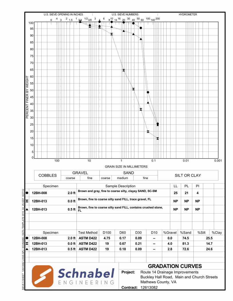
0
5
10
15
20
25
30
35
40
45
50
55
60
65
70
75
80
85
90
95
100
0.0010.010.1110100
U.S. SIEVE OPENING IN INCHES
200100 140604023 3/41.5 6 81041
25.5
14.7
24.6
HYDROMETER
6
Brown and gray, fine to coarse silty, clayey SAND, SC-SM
Brown, fine to coarse silty sand FILL, trace gravel, FL
Brown, fine to coarse silty sand FILL, contains crushed stone,FL
Specimen
2.0 ft
0.0 ft
0.5 ft
2.0 ft
0.0 ft
0.5 ft
16 2014
%SandD30D60
ASTM D422
ASTM D422
ASTM D422
Test Method D10D100
LL
U.S. SIEVE NUMBERS
5030
GRADATION CURVES
4 3
GRAIN SIZE IN MILLIMETERS
PE
RC
EN
T F
INE
R B
Y W
EIG
HT
1/23/8
PL PI
0.0
4.0
2.8
12BH-008
12BH-013
12BH-013
25
NP
NP
21
NP
NP
4
NP
NP
%Clay
12BH-008
12BH-013
12BH-013
%Silt%GravelSpecimen
Sample Description
4.75
19
19
0.17
0.67
0.18
0.09
0.21
0.09
--
--
--
74.5
81.3
72.6
Project: Route 14 Drainage ImprovementsBuckley Hall Road, Main and Church StreetsMathews County, VA
Contract: 12613082SIE
VE
5 S
HE
ET
126
130
82 L
OG
S.G
PJ
SC
HN
AB
EL
DA
TA
TE
MP
LAT
E 2
010_
02_
25.G
DT
9/
27/1
2
fine coarseCOBBLES SILT OR CLAY
medium fine
SANDGRAVELcoarse

109.0
110.0
111.0
112.0
113.0
114.0
115.0
116.0
117.0
118.0
119.0
120.0
121.0
6 8 10 12 14 16 18
VTM1
Comments:Bulk sample obtained from auger cuttings over
the depth interval of 1.0 to 5.0 ft.
DR
Y D
EN
SIT
Y,
pcf
MOISTURE DENSITY RELATIONSHIP
118.3
11.7
Test Methods:
Sample Description:
Opt. Moisture (%):
Max. Dry Density (pcf):
Assumed Specific Gravity:
Sample Source: 12BH-004, 1.0 ft
Gray, fine to coarse silty SAND, tracegravel, SM
2.63
9-12-12Date: DSReviewed By:
WATER CONTENT, %
Liquid Limit (LL): NP
Plasticity Index (PI): NP
% Retained #4 Sieve: 0.2
% Passing # 200 Sieve: 30.6
Project: Route 14 Drainage ImprovementsBuckley Hall Road, Main and Church StreetsMathews County, VA
Contract: 12613082CO
MP
AC
TIO
N 1
2613
082
LO
GS
.GP
J S
CH
NA
BE
L D
AT
A T
EM
PLA
TE
200
8_04
_22
.GD
T
9/27
/12
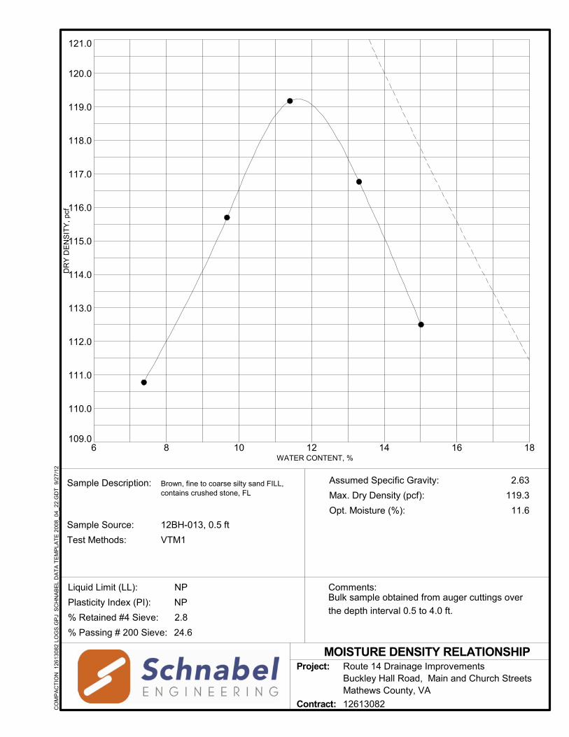
109.0
110.0
111.0
112.0
113.0
114.0
115.0
116.0
117.0
118.0
119.0
120.0
121.0
6 8 10 12 14 16 18
VTM1
Comments:Bulk sample obtained from auger cuttings over
the depth interval 0.5 to 4.0 ft.
DR
Y D
EN
SIT
Y,
pcf
MOISTURE DENSITY RELATIONSHIP
119.3
11.6
Test Methods:
Sample Description:
Opt. Moisture (%):
Max. Dry Density (pcf):
Assumed Specific Gravity:
Sample Source: 12BH-013, 0.5 ft
Brown, fine to coarse silty sand FILL,contains crushed stone, FL
2.63
WATER CONTENT, %
Liquid Limit (LL): NP
Plasticity Index (PI): NP
% Retained #4 Sieve: 2.8
% Passing # 200 Sieve: 24.6
Project: Route 14 Drainage ImprovementsBuckley Hall Road, Main and Church StreetsMathews County, VA
Contract: 12613082CO
MP
AC
TIO
N 1
2613
082
LO
GS
.GP
J S
CH
NA
BE
L D
AT
A T
EM
PLA
TE
200
8_04
_22
.GD
T
9/27
/12

Consolidation TestTest Results
1.00
3.00
5.00
7.00
9.00
11.00
Stra
in (%
)
Page 1 of 1
Before After Liquid Limits: 28 Test Date: 8-31-1225.92 24.34 Plastic Limits: 15
Dry Density (pcf): 96.33 106.00 Plasticity Index (%): 13Saturation (%): 94.29 112.78Void Ratio: 0.7347 0.5097 Specific Gravity: 2.680 AssumedSample Description: Gray, fne to coarse clayey SAND, SCProject Number: 12613082 Depth: 5'-7' Remarks:Sample Number: 12BH-004 Boring Number: 12BH-004Project: Route 14 & Route 611 Drainage Improvements
Location: Mathews County, VA
Moisture (%):
Gray, fine to coarse clayey SAND, SC
13.00
15.000.100 1.000 10.000 100.000
Pressure (tsf)
Page 1 of 1

Project: Route 14 & Route 611 Drainage Improvements Project Number: 12613082Location: Mathews County, VAJob Number: 12613082
Sample Number: 12BH-004 Sample Description:Boring Number: 12BH-004 Gray, fne to coarse clayey SAND, SCDepth: 5'-7' Remarks:Sample Type: Undisturbed Test Date: 8-31-12
Load Sequence
Cummulative Change in
HeightSpecimen
HeightHeight of
VoidVertical Strain Void Ratio
t90 Fitting Time
t50 Fitting Time t90 Cv t50 Cv
(tsf) (in) (in) (in) (%) (min) (min) (ft2/year) (ft2/year)0.000 0.0000 1.0000 0.4232 0.00 0.7337 0.000 0.000 0.000 0.0000.125 0.0100 0.9900 0.4132 1.00 0.7163 1.154 * 0.6410 657.259 274.8600.250 0.0166 0.9834 0.4066 1.66 0.7049 1.524 * 0.8468 490.931 205.2950.500 0.0289 0.9711 0.3943 2.89 0.6836 1.357 * 0.7538 537.821 224.8901.000 0.0471 0.9529 0.3761 4.71 0.6520 1.325 * 0.7362 530.243 221.7162.000 0.0703 0.9297 0.3529 7.03 0.6118 1.328 * 0.7380 503.491 210.5370.500 0.0694 0.9306 0.3538 6.94 0.6134 0.000 0.000 0.000 0.0000.125 0.0665 0.9335 0.3567 6.65 0.6184 0.000 0.000 0.000 0.0000.500 0.0682 0.9318 0.3550 6.82 0.6154 0.895 * 0.4974 750.343 313.7902.000 0.0746 0.9254 0.3486 7.46 0.6043 1.032 * 0.5734 642.069 268.4734.000 0.1021 0.8979 0.3211 10.21 0.5567 1.344 * 0.7467 464.188 194.0938.000 0.1164 0.8836 0.3068 11.64 0.5319 2.036 * 1.1311 296.725 124.082
16.000 0.1415 0.8585 0.2817 14.15 0.4884 1.334 * 0.7410 427.588 178.7982.000 0.1386 0.8614 0.2846 13.86 0.4934 0.000 0.000 0.000 0.0000.125 0.1297 0.8703 0.2935 12.97 0.5088 0.000 0.000 0.000 0.000
Predicted value indicated with *
Tested By: RG Checked By: DS
14
10111213
6789
345
Consolidation Test ResultsSummary
Index
10
2
Page 1 of 1
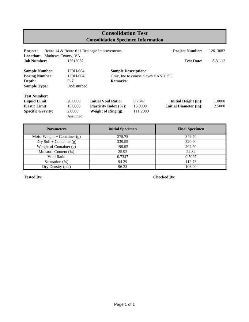
Project: Route 14 & Route 611 Drainage Improvements Project Number: 12613082Location: Mathews County, VAJob Number: 12613082 Test Date: 8-31-12
Sample Number: 12BH-004 Sample Description:Boring Number: 12BH-004 Gray, fne to coarse clayey SAND, SCDepth: 5'-7' Remarks:Sample Type: Undisturbed
Test Number:Liquid Limit: 28.0000 Initial Void Ratio: 0.7347 Initial Height (in): 1.0000Plastic Limit: 15.0000 Plasticity Index (%): 13.0000 Initial Diameter (in): 2.5000Specific Gravity: 2.6800 Weight of Ring (g): 111.2000
Assumed
Tested By: Checked By:
Void RatioSaturation (%)
Dry Density (pcf)
349.70320.90202.60
Moist Weight + Container (g)Dry Soil + Container (g)Weight of Container (g)Moisture Content (%) 24.34
375.75339.55199.9525.92
Consolidation TestConsolidation Specimen Information
Parameters Final SpecimenInitial Specimen
0.5097112.78106.00
0.734794.2996.33
Page 1 of 1

Consolidation Test Results(Sequence 8) Load 0.500 tsf
0.0684
0.0689
0.0694
0.0699
0.0704
0.0709
0.0 5.0 10.0 15.0 20.0 25.0 30.0 35.0 40.0
Dis
plac
emen
t (in
)
Time (Square Root Minute)
Consolidation Graph (Squareroot Time)
Load8Sqr Line1 Line2 Point1
Consolidation Graph (Logarithmic Time)
Load8Log
Page 2 of 2
0.0685
0.0690
0.0695
0.0700
0.0705
0.07100.01 0.10 1.00 10.00 100.00 1000.00 10000.00
Dis
plac
emen
t (in
)
Time (Logarithmic Minute)
Consolidation Graph (Logarithmic Time)
Load8Log
Page 2 of 2

Consolidation Test Results(Sequence 10) Load 4.000 tsf
0.0816
0.0866
0.0916
0.0966
0.1016
0.10660.0 5.0 10.0 15.0 20.0 25.0 30.0 35.0 40.0
Dis
plac
emen
t (in
)
Time (Square Root Minute)
Consolidation Graph (Squareroot Time)
Load10Sqr Line1 Line2 Point1
Consolidation Graph (Logarithmic Time)
Load10Log
Page 2 of 2
0.0800
0.0850
0.0900
0.0950
0.1000
0.1050
0.01 0.10 1.00 10.00 100.00 1000.00 10000.00
Dis
plac
emen
t (in
)
Time (Logarithmic Minute)
Consolidation Graph (Logarithmic Time)
Load10Log
Page 2 of 2

APPENDIX C
SETTLEMENT CALCULATIONS
Double 7’x4’ Culvert Settlement (2 Sheets) Quadruple 5’x3’ Culvert Settlement (2 Sheets) Junction Box 4-1 Settlement (2 Sheets) Junction Box 4-4 Settlement (2 Sheets)
October 1, 2012 Schnabel Engineering Consultants, Inc. Project 12613082 ©2012 All Rights Reserved

16676
756.6Initials: 0.71Initials: 6
1 0 2 Schmertmann 120 4 S2 no 402 2 4 Boussinesq 110 0.3 0.1 0.01
Date
Double 7' x 4' Box Culvert (12BH-005)
Schmertmann & One Dimensional Consolidation
E. Drahos
Project NameProject LocationJob Number
Route 14 Drainage Improvements
Spread Footing Settlement Calculation
Net Precon. (pc - po)
(tsf)
Comp. Ratio CR
Mathews County
Depth to Water Table (ft)
Recomp. Ratio RR
Bottom of Layer (ft)
Calculation Method
12613082
Project Data
September 6, 2012
DescriptionCalculated ByChecked By
LayerTop of
Layer (ft)
Soil Properties
J. Ruffin / B. Azumah
Foundation DetailsFooting Width B (ft)Footing Length L (ft)Footing Depth (ft)Footing Load (kips)Footing Bearing Pressure (ksf)
Modulus (tsf) or
Uncorrected N-value
Soil Modulus
(tsf)Modulus
Correlation
Correct for Auto
Hammer?
Total Unit Weight
(pcf)
Schnabel Engineering, LLC Page 1 of 2
3 4 8 Schmertmann 120 3 S2 no 304 8 12 Schmertmann 120 5 S2 no 505 12 17 Schmertmann 120 21 S2 no 2106 17 22 Schmertmann 120 2 S2 no 207 22 70 Boussinesq 110 1.0 0.1 0.0189
1011121314151617181920
Schnabel Engineering, LLC Page 1 of 2

TotalBottom Layer Cumulative Of Layer Calculation Top of Bottom Top of Bottom Top of Bottom Top of Bottom Settlement Settlement
Layer (ft) Method Layer of Layer Layer of Layer Layer of Layer Layer of Layer (inches) (inches)1 2 Schmertmann 0 240 0.00 0.002 4 Boussinesq 240 460 840 1060 #N/A #N/A #N/A #N/A 0.00 0.003 8 Schmertmann 460 815 0.03 0.034 12 Schmertmann 815 1046 0.07 0.105 17 Schmertmann 1046 1334 0.03 0.136 22 Schmertmann 1334 1622 0.29 0.417 70 Boussinesq 1622 3906 3622 5906 373 73 1994 3979 0.11 0.5289
1011121314151617181920
Pressure pc (psf) po (psf)Total Pressurepo + Δp (psf)
Overburden Pressure Applied PressureΔp (psf)
Preconsolidation
Schnabel Engineering, LLC Page 2 of 2
20
Schnabel Engineering, LLC Page 2 of 2

232685
13.908Initials: 0.60Initials: 6
1 0 2 Schmertmann 120 13 S2 no 1592 2 4 Schmertmann 120 8 S2 no 98
Modulus (tsf) or
Uncorrected N-value
Soil Modulus
(tsf)Modulus
Correlation
Correct for Auto
Hammer?
Total Unit Weight
(pcf)
J. Ruffin / B. Azumah
Foundation DetailsFooting Width B (ft)Footing Length L (ft)Footing Depth (ft)Footing Load (kips)Footing Bearing Pressure (ksf)
Project Data
September 6, 2012
DescriptionCalculated ByChecked By
LayerTop of
Layer (ft)
Soil PropertiesNet
Precon. (pc - po)
(tsf)
Comp. Ratio CR
Mathews County
Depth to Water Table (ft)
Recomp. Ratio RR
Bottom of Layer (ft)
Calculation Method
12613082
Date
Quad 5' x 3' Box Culvert (12BH-002)
Schmertmann & One Dimensional Consolidation
E. Drahos
Project NameProject LocationJob Number
Route 14 Drainage Improvements
Spread Footing Settlement Calculation
Schnabel Engineering, LLC Page 1 of 2
3 4 6 Schmertmann 120 3 S2 no 374 6 8 Boussinesq 120 0.3 0.1 0.015 8 17 Schmertmann 120 3 S2 no 376 17 23 Schmertmann 120 5 S2 no 617 23 30 Boussinesq 110 0.5 0.1 0.018 30 50 Boussinesq 110 1.0 0.1 0.019
1011121314151617181920
Schnabel Engineering, LLC Page 1 of 2
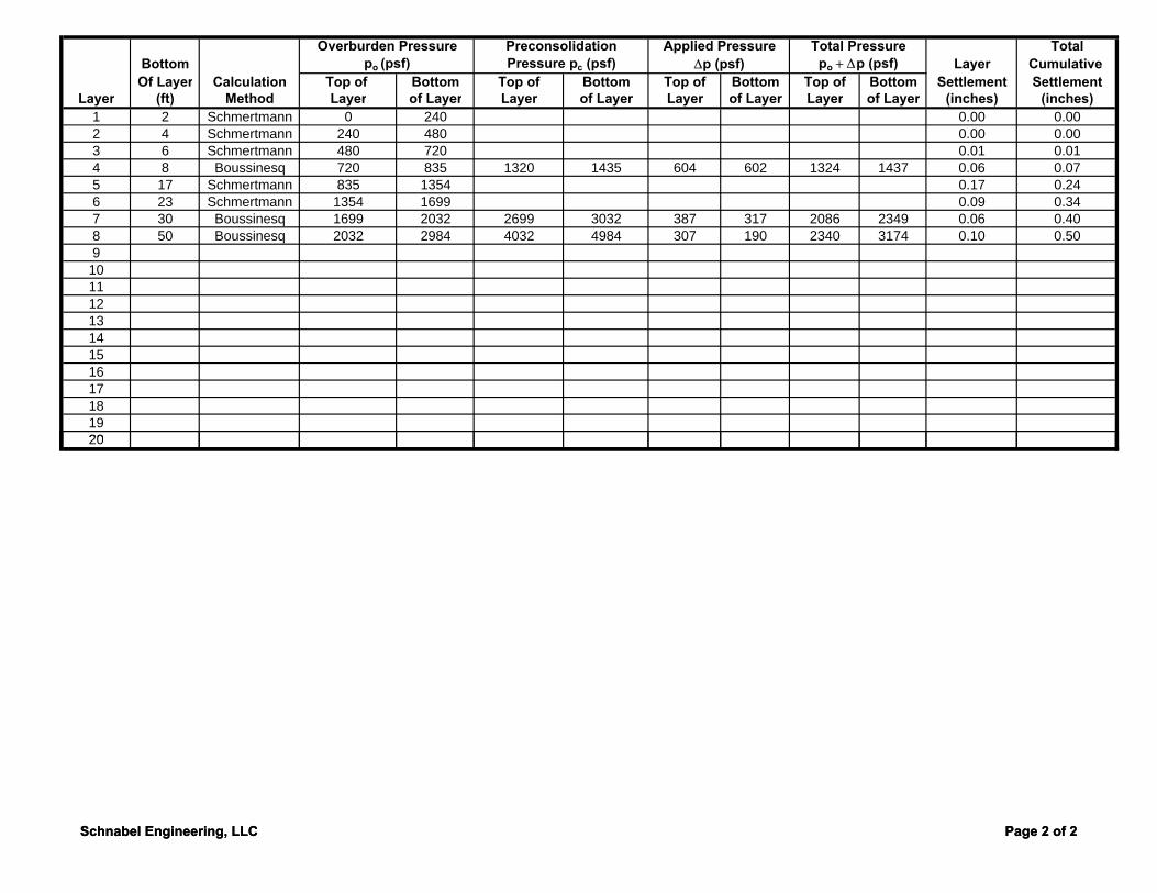
TotalBottom Layer Cumulative Of Layer Calculation Top of Bottom Top of Bottom Top of Bottom Top of Bottom Settlement Settlement
Layer (ft) Method Layer of Layer Layer of Layer Layer of Layer Layer of Layer (inches) (inches)1 2 Schmertmann 0 240 0.00 0.002 4 Schmertmann 240 480 0.00 0.003 6 Schmertmann 480 720 0.01 0.014 8 Boussinesq 720 835 1320 1435 604 602 1324 1437 0.06 0.075 17 Schmertmann 835 1354 0.17 0.246 23 Schmertmann 1354 1699 0.09 0.347 30 Boussinesq 1699 2032 2699 3032 387 317 2086 2349 0.06 0.408 50 Boussinesq 2032 2984 4032 4984 307 190 2340 3174 0.10 0.509
1011121314151617181920
Overburden Pressure Applied PressureΔp (psf)
Preconsolidation Total Pressurepo + Δp (psf)Pressure pc (psf) po (psf)
Schnabel Engineering, LLC Page 2 of 2
20
Schnabel Engineering, LLC Page 2 of 2

13203
100Initials: 0.38Initials: 7
1 0 2 Schmertmann 120 33 S2 no 2962 2 4 Schmertmann 120 11 S2 no 99
Date
Junction Box 4-1 (12BH-007)
Schmertmann & One Dimensional Consolidation
E. Drahos
Project NameProject LocationJob Number
Route 14 Drainage Improvements
Spread Footing Settlement Calculation
Net Precon. (pc - po)
(tsf)
Comp. Ratio CR
Mathews County
Depth to Water Table (ft)
Recomp. Ratio RR
Bottom of Layer (ft)
Calculation Method
12613082
Project Data
September 6, 2012
DescriptionCalculated ByChecked By
LayerTop of
Layer (ft)
Soil Properties
J. Ruffin / B. Azumah
Foundation DetailsFooting Width B (ft)Footing Length L (ft)Footing Depth (ft)Footing Load (kips)Footing Bearing Pressure (ksf)
Modulus (tsf) or
Uncorrected N-value
Soil Modulus
(tsf)Modulus
Correlation
Correct for Auto
Hammer?
Total Unit Weight
(pcf)
Schnabel Engineering, LLC Page 1 of 2
3 4 6 Schmertmann 120 3 S2 no 274 6 13 Schmertmann 120 1 S2 no 95 13 17 Schmertmann 120 29 S2 no 2606 17 23 Schmertmann 120 3 S2 no 277 23 50 Boussinesq 110 0.5 0.1 0.0189
1011121314151617181920
Schnabel Engineering, LLC Page 1 of 2
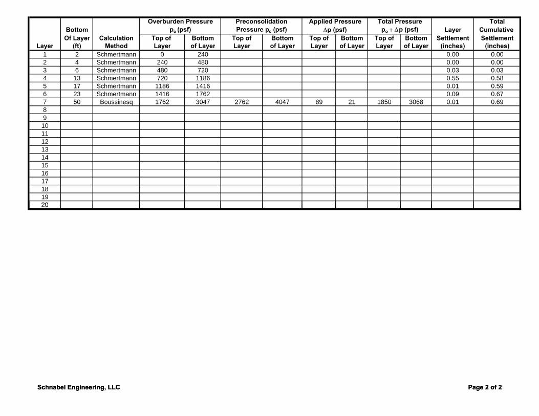
TotalBottom Layer Cumulative Of Layer Calculation Top of Bottom Top of Bottom Top of Bottom Top of Bottom Settlement Settlement
Layer (ft) Method Layer of Layer Layer of Layer Layer of Layer Layer of Layer (inches) (inches)1 2 Schmertmann 0 240 0.00 0.002 4 Schmertmann 240 480 0.00 0.003 6 Schmertmann 480 720 0.03 0.034 13 Schmertmann 720 1186 0.55 0.585 17 Schmertmann 1186 1416 0.01 0.596 23 Schmertmann 1416 1762 0.09 0.677 50 Boussinesq 1762 3047 2762 4047 89 21 1850 3068 0.01 0.6989
1011121314151617181920
Pressure pc (psf) po (psf)Total Pressurepo + Δp (psf)
Overburden Pressure Applied PressureΔp (psf)
Preconsolidation
Schnabel Engineering, LLC Page 2 of 2
20
Schnabel Engineering, LLC Page 2 of 2

7204
68Initials: 0.49Initials: 7
1 0 2 Schmertmann 120 3 S2 no 282 2 4 Schmertmann 120 3 S2 no 28
Modulus (tsf) or
Uncorrected N-value
Soil Modulus
(tsf)Modulus
Correlation
Correct for Auto
Hammer?
Total Unit Weight
(pcf)
J. Ruffin / B. Azumah
Foundation DetailsFooting Width B (ft)Footing Length L (ft)Footing Depth (ft)Footing Load (kips)Footing Bearing Pressure (ksf)
Project Data
September 6, 2012
DescriptionCalculated ByChecked By
LayerTop of
Layer (ft)
Soil PropertiesNet
Precon. (pc - po)
(tsf)
Comp. Ratio CR
Mathews County
Depth to Water Table (ft)
Recomp. Ratio RR
Bottom of Layer (ft)
Calculation Method
12613082
Date
Settlement Junction Box 4-4 (12BH-008)
Schmertmann & One Dimensional Consolidation
E. Drahos
Project NameProject LocationJob Number
Route 14 Drainage Improvements
Spread Footing Settlement Calculation
Schnabel Engineering, LLC Page 1 of 2
3 4 6 Schmertmann 120 2 S2 no 194 6 13 Schmertmann 120 1 S2 no 95 13 17 Schmertmann 120 22 S2 no 2086 17 23 Schmertmann 120 1 S2 no 97 23 30 Boussinesq 110 0.5 0.1 0.018 30 50 Boussinesq 110 1.0 0.1 0.019
1011121314151617181920
Schnabel Engineering, LLC Page 1 of 2

TotalBottom Layer Cumulative Of Layer Calculation Top of Bottom Top of Bottom Top of Bottom Top of Bottom Settlement Settlement
Layer (ft) Method Layer of Layer Layer of Layer Layer of Layer Layer of Layer (inches) (inches)1 2 Schmertmann 0 240 0.00 0.002 4 Schmertmann 240 480 0.00 0.003 6 Schmertmann 480 720 0.04 0.044 13 Schmertmann 720 1186 0.57 0.625 17 Schmertmann 1186 1416 0.01 0.626 23 Schmertmann 1416 1762 0.01 0.637 30 Boussinesq 1762 2095 2762 3095 69 44 1831 21398 50 Boussinesq 2095 3047 4095 5047 41 15 2136 30629
1011121314151617181920
Overburden Pressure Applied PressureΔp (psf)
Preconsolidation Total Pressurepo + Δp (psf)Pressure pc (psf) po (psf)
Schnabel Engineering, LLC Page 2 of 2
20
Schnabel Engineering, LLC Page 2 of 2