geotechnical and salinity investigation report · geotechnical and salinity investigation report...
TRANSCRIPT

172 Tallawong Road, Rouse Hill NE149.1-17
0
GEOTECHNICAL AND SALINITY INVESTIGATION REPORT
ADDRESS: 172 Tallawong Road, Rouse Hill
CLIENT: JS Architects Pty Ltd
DATE: 5 June 2017
REPORT NO: NE149.1-17
GEOTESTA PTY LTD | ABN 91851620815 | 44 Mary Parade, Rydalmere NSW 2116
Phone: 1300 852216 | Fax: 03 9562 9098 | email: [email protected]
172 Tallawong Road, Rouse Hill NE149.1-17
1
TABLE OF CONTENTS 1. INTRODUCTION ............................................................................................................... 3
2. FIELD INVESTIGATION .................................................................................................. 4
3. FINDINGS ........................................................................................................................... 5
3.1 Site Topography ..............................................................................................................5
3.2 Site Geology ....................................................................................................................5
3.3 Soil/Rock Profile ..............................................................................................................6
3.4 Site Classification .............................................................................................................7
3.5 Groundwater ...................................................................................................................7
3.6 Laboratory Testing and Analysis – Geotechnical .............................................................7
3.7 Laboratory Testing and Analysis - Soil Contamination ....................................................7
3.7.1 Salinity Classification ..............................................................................................8
3.7.2 Results – Exposure Classification ............................................................................8
4. FOUNDATION RECOMMENDATION ....................................................................... 10
4.1 Strip/Pad Footing System............................................................................................... 10
4.2 Slab on Ground .............................................................................................................. 10
4.3 Bored Piers or Screw Piles .............................................................................................. 11
4.3.1 Pile Construction Considerations .......................................................................... 12
5. EXCAVATION, RETAINING WALL & LATERAL EARTH PRESSURES .............. 13
5.1 Temporary Cut Batter and Excavation ........................................................................... 13
5.3 Lateral Earth Pressures .................................................................................................. 13
5.4 Anchored Soldier Pile Retention Systems ....................................................................... 14
5.5 Ground Anchors ............................................................................................................ 15
5.6 Estimated Wall Deflections and Ground Settlements ..................................................... 15
5.7 Drainage of Retention Systems....................................................................................... 16
5.8 Basement Floor Construction ......................................................................................... 16
6. REFERENCES .................................................................................................................... 18
Table Index
Table 1: Summary of Sub-surface Materials 6
Table 2: Summary of Laboratory Test Results 7
Table 3: Salinity test results 8
Table 4: Exposure classification test results 8
Table 5: Soil Aggresivity Testing Results 9
Table 6: Allowable Bearing Capacities for Pad/Strip Footings 10
Table 7: Geotechnical parameters for Slab on Ground Footings 11
Table 8: Allowable Skin Friction and End Bearing Capacity 12
Table 9: Materials Strength Parameters 14
Figures
Figure 1: Site Plan and Borehole Locations 4
Figure 2: Geology Map of the Site with Package Code 5

172 Tallawong Road, Rouse Hill NE149.1-17
2
Appendices Borehole Logs Laboratory Test Results
172 Tallawong Road, Rouse Hill NE149.1-17
3
1. INTRODUCTION
Geotesta was engaged by JS Architects Pty Ltd to conduct geotechnical investigation
including soil contamination assessment at 172 Tallawong Road, Rouse Hill NSW. The
proposed residential development includes 115 residential units with double basement
levels.
The field work was carried out on 22 May 2017. This report presents the geotechnical
investigation results including sub-surface soil profile with interpreted geotechnical
properties of the assessed subsurface lithology, laboratory test results (Atterberg
limits), soil classification, recommendations on the design parameters of footing,
geotechnical parameters including allowable bearing capacity, shaft friction, friction
angle, cohesion, and young’s modulus.
The scope of report also included laboratory chemical analysis on collected soil
samples, reporting chemical characteristic of the soil in relation to salinity and
aggresivity and comments on laboratory test results and recommendations. The soil
contamination assessment is to provide information on the soil contamination for the
future construction of residential development. This assessment has been carried out
in general accordance with the following guidelines:
The soil contamination assessment is performed in accordance with AS4482.1 - 2005,
AS4482.2 – 2005;
Department of Land and Water Conservation (DLWC, 2002), Site Investigations for
Urban Salinity;
Western Sydney Salinity Code of Practice March 2003 (Amended January 2004);
Australian Standard (AS) 3600 (2009), Concrete Structures;
The National Environment Protection Council (NEPC), amended on 30 April 2013
and
Other relevant NSW guidelines and legislation.
The soil contamination assessment was conducted in general accordance with the
Australian Standards. The salinity assessment was carried out with reference to the
Department of Infrastructure Planning and Natural Resources (DIPNR) publications.
172 Tallawong Road, Rouse Hill NE149.1-17
4
2. FIELD INVESTIGATION
The investigation involved of total eight (8) boreholes to a maximum depth of 4.5m for
the proposed residential development.
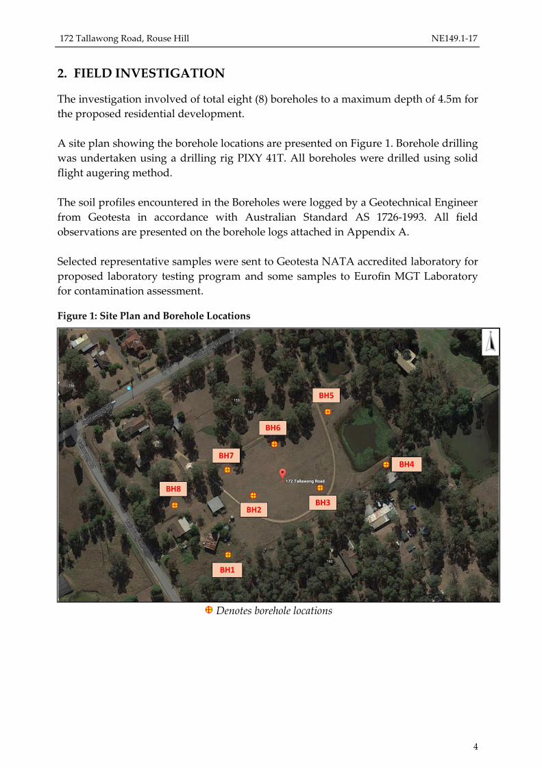
A site plan showing the borehole locations are presented on Figure 1. Borehole drilling
was undertaken using a drilling rig PIXY 41T. All boreholes were drilled using solid
flight augering method.
The soil profiles encountered in the Boreholes were logged by a Geotechnical Engineer
from Geotesta in accordance with Australian Standard AS 1726-1993. All field
observations are presented on the borehole logs attached in Appendix A.
Selected representative samples were sent to Geotesta NATA accredited laboratory for
proposed laboratory testing program and some samples to Eurofin MGT Laboratory
for contamination assessment.
Figure 1: Site Plan and Borehole Locations
Denotes borehole locations
172 Tallawong Road, Rouse Hill NE149.1-17
5
3. FINDINGS
3.1 Site Topography
The proposed site at 172 Tallawong Road in Rouse Hill is gently sloping from west to
east. The proposed site is covered by grass with medium to tall trees observed on the
perimeter of the site. There is a man-made dam at the eastern corner of the site (Figure
1).
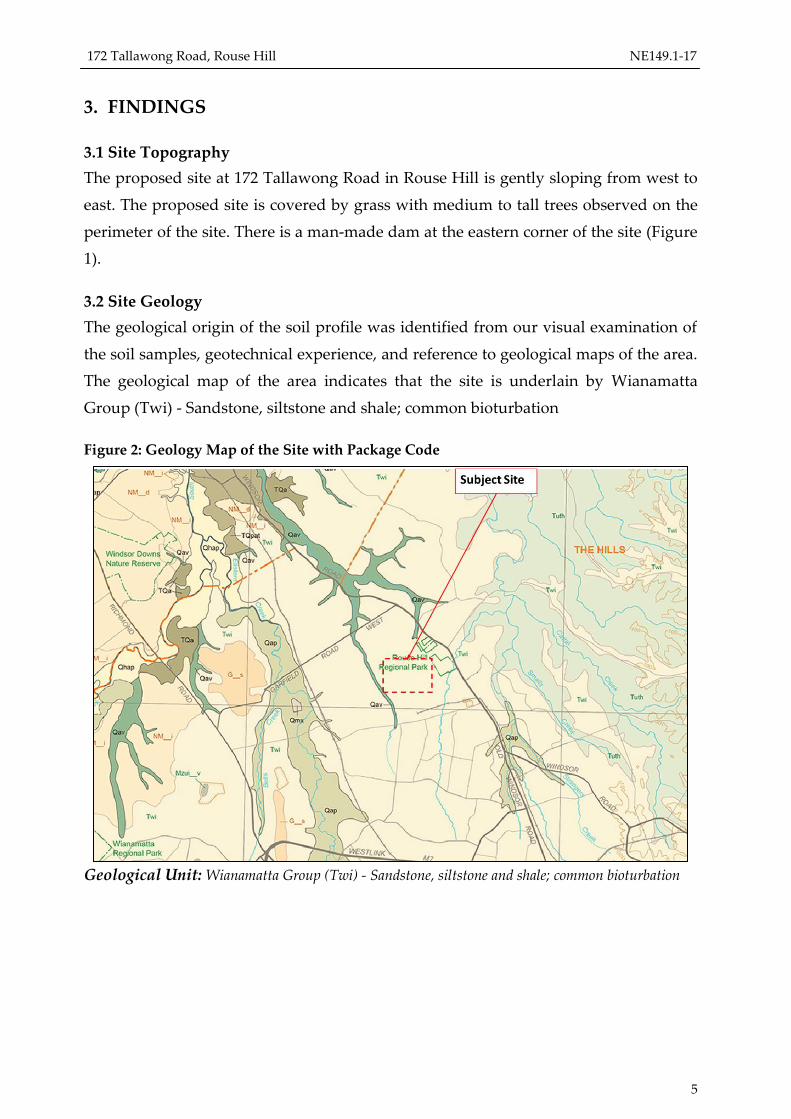
3.2 Site Geology
The geological origin of the soil profile was identified from our visual examination of
the soil samples, geotechnical experience, and reference to geological maps of the area.
The geological map of the area indicates that the site is underlain by Wianamatta
Group (Twi) - Sandstone, siltstone and shale; common bioturbation
Figure 2: Geology Map of the Site with Package Code
Geological Unit: Wianamatta Group (Twi) - Sandstone, siltstone and shale; common bioturbation

172 Tallawong Road, Rouse Hill NE149.1-17
6
3.3 Soil/Rock Profile
The encountered soil profiles are presented in the borehole logs in Appendix A and
tabulated in detail in the Table 1 below.
Table 1: Summary of Sub-surface Materials
Borehole
No.
Depth
(m) Soil/Rock Type
Compaction
Level/Consistency
BH 1
0-0.5 Fill Well compacted
0.5-1.0 Silty CLAY Firm
1.0-1.5 Silty CLAY Stiff to very stiff
1.5-2.0 Silty CLAY Hard
2.0-3.0 Silty CLAY with Shale fragments Hard
BH 2
0-0.3 Fill Well compacted
0.3-0.85 Silty CLAY Stiff to very stiff to hard
BH 3
0-0.3 Fill Well compacted
0.3-0.6 Silty CLAY Stiff
0.6-1.35 Silty CLAY Very stiff to hard
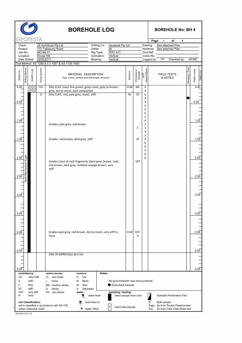
BH 4
0-0.2 Fill Well compacted
0.2-2.0 Silty CLAY Firm to stiff
2.0-4.0 Silty CLAY Very stiff
4.0-4.5 Silty CLAY Very stiff to hard
BH 5
0-0.3 Fill Well compacted
0.3-1.7 Silty CLAY Stiff to very stiff
1.7-2.4 Silty CLAY with Shale fragments Hard
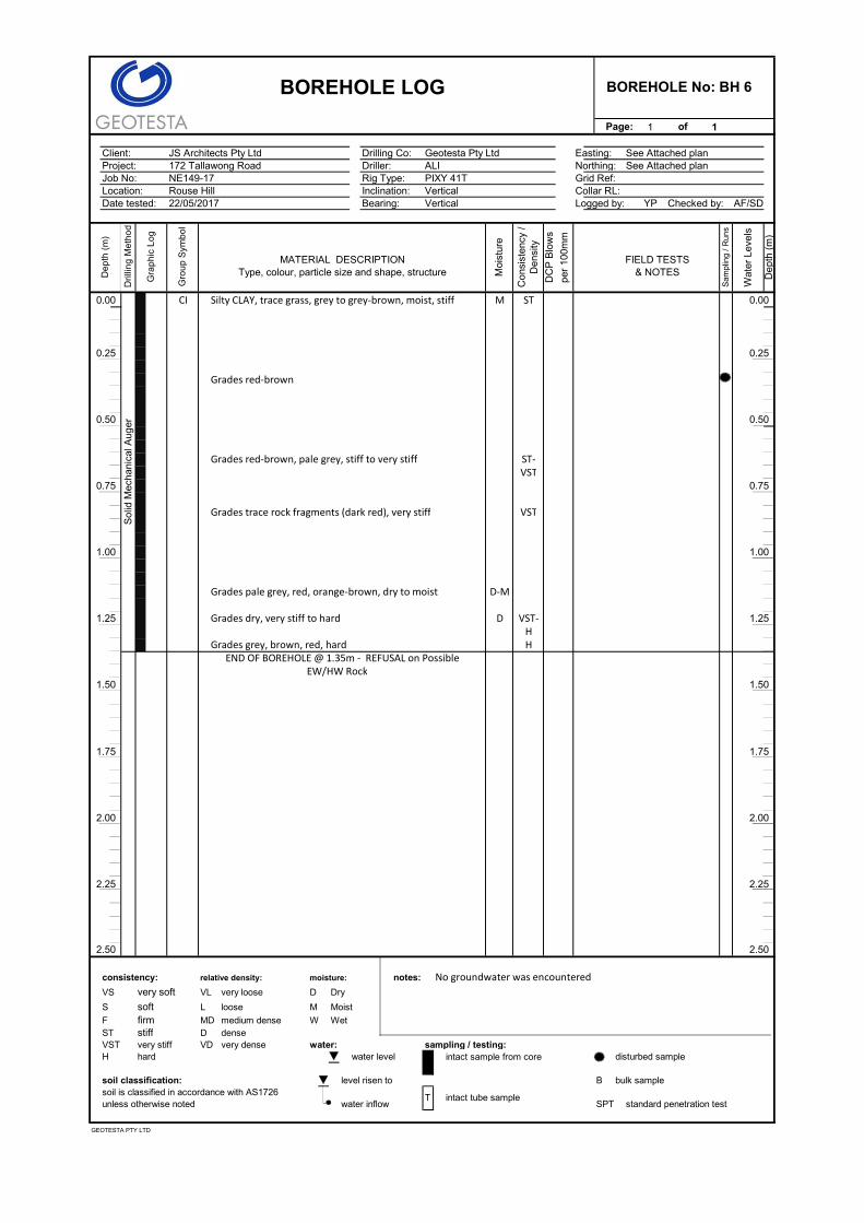
BH 6 0-0.80 Silty CLAY Stiff to very stiff
0.8-1.35 Silty CLAY Very stiff to hard
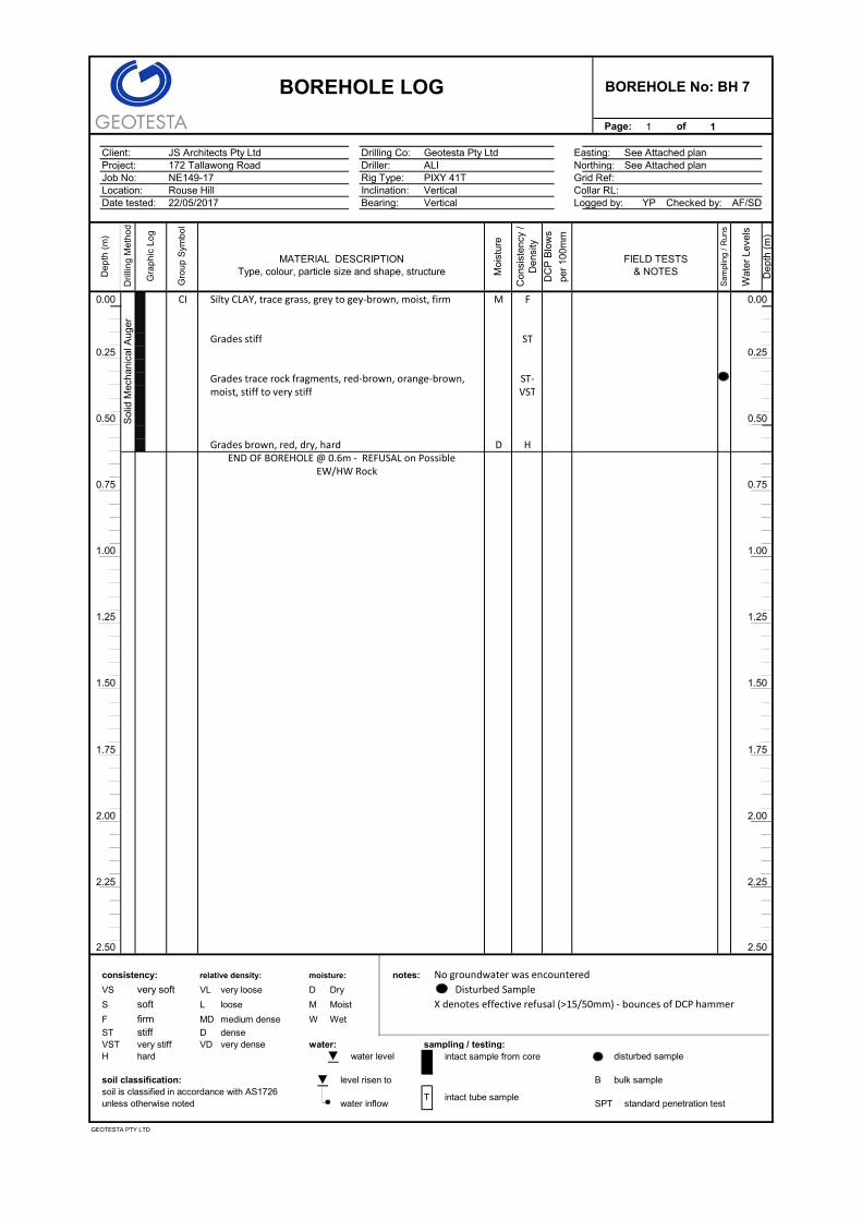
BH 7 0-0.40 Silty CLAY Firm to stiff
0.4-0.6 Silty CLAY Very stiff to hard
BH 8
0-0.40 Silty CLAY Stiff to very stiff
0.4-0.8 Silty CLAY Very stiff to hard
0.8-4.0 Silty CLAY Hard
172 Tallawong Road, Rouse Hill NE149.1-17
7
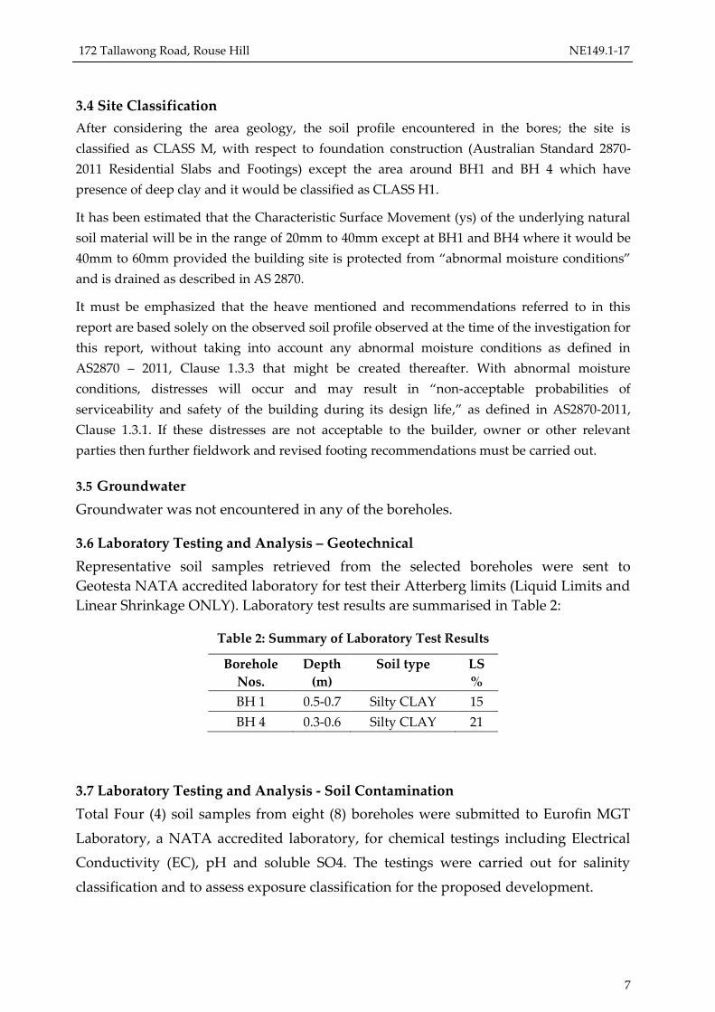
3.4 Site Classification
After considering the area geology, the soil profile encountered in the bores; the site is
classified as CLASS M, with respect to foundation construction (Australian Standard 2870-
2011 Residential Slabs and Footings) except the area around BH1 and BH 4 which have
presence of deep clay and it would be classified as CLASS H1.
It has been estimated that the Characteristic Surface Movement (ys) of the underlying natural
soil material will be in the range of 20mm to 40mm except at BH1 and BH4 where it would be
40mm to 60mm provided the building site is protected from “abnormal moisture conditions”
and is drained as described in AS 2870.
It must be emphasized that the heave mentioned and recommendations referred to in this
report are based solely on the observed soil profile observed at the time of the investigation for
this report, without taking into account any abnormal moisture conditions as defined in
AS2870 – 2011, Clause 1.3.3 that might be created thereafter. With abnormal moisture
conditions, distresses will occur and may result in “non-acceptable probabilities of
serviceability and safety of the building during its design life,” as defined in AS2870-2011,
Clause 1.3.1. If these distresses are not acceptable to the builder, owner or other relevant
parties then further fieldwork and revised footing recommendations must be carried out.
3.5 Groundwater
Groundwater was not encountered in any of the boreholes.
3.6 Laboratory Testing and Analysis – Geotechnical
Representative soil samples retrieved from the selected boreholes were sent to
Geotesta NATA accredited laboratory for test their Atterberg limits (Liquid Limits and
Linear Shrinkage ONLY). Laboratory test results are summarised in Table 2:
Table 2: Summary of Laboratory Test Results
Borehole
Nos.
Depth
(m)
Soil type LS
%
BH 1 0.5-0.7 Silty CLAY 15
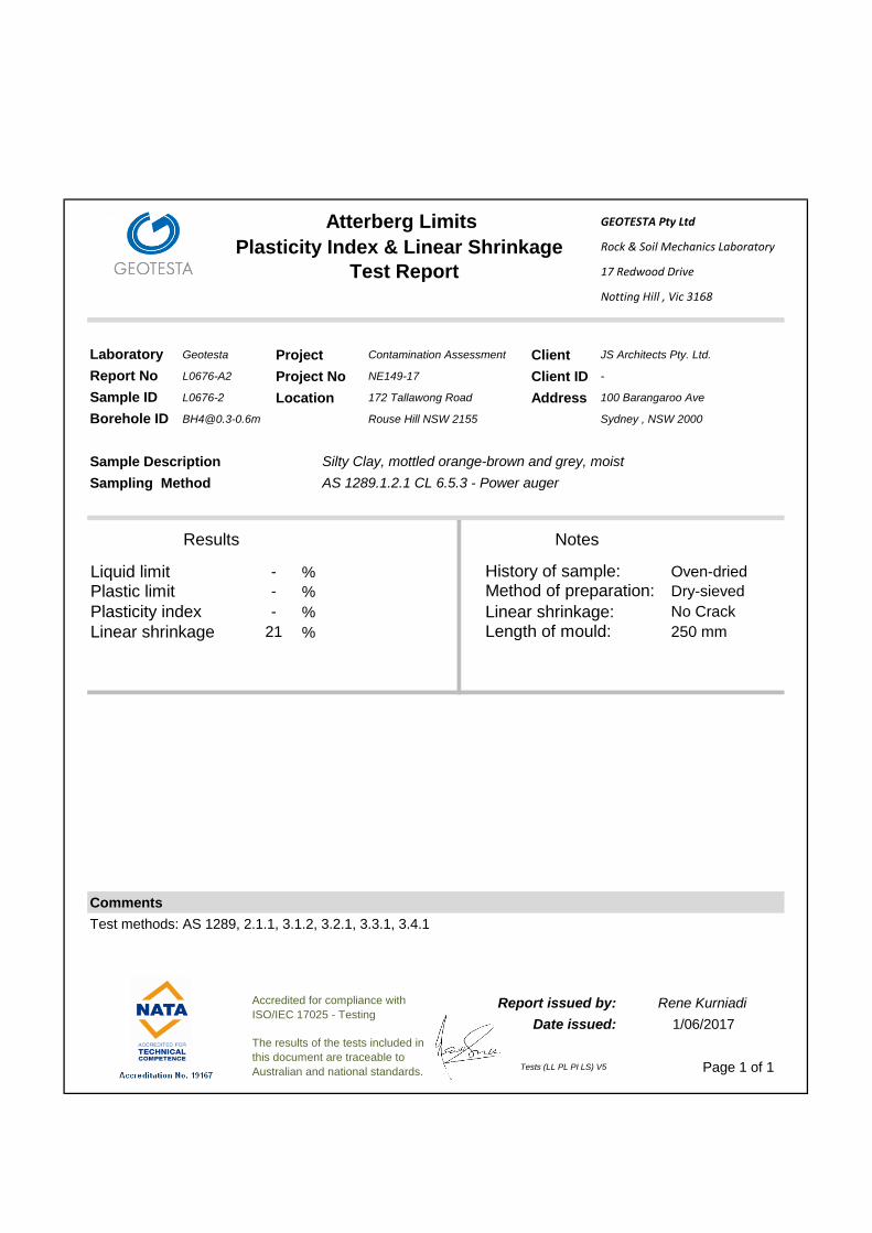
BH 4 0.3-0.6 Silty CLAY 21
3.7 Laboratory Testing and Analysis - Soil Contamination
Total Four (4) soil samples from eight (8) boreholes were submitted to Eurofin MGT
Laboratory, a NATA accredited laboratory, for chemical testings including Electrical
Conductivity (EC), pH and soluble SO4. The testings were carried out for salinity
classification and to assess exposure classification for the proposed development.

172 Tallawong Road, Rouse Hill NE149.1-17
8
Sampling was targeted to achieve a representative coverage of site conditions in line
with assessed sub-surface profiles, proposed development, and the investigation
scope.
Analysis Frequency Analyses
4 Samples Salinity suite including Electrical Conductivity (EC),
pH and soluble SO4
3.7.1 Salinity Classification
Laboratory test results for salinity classification are summarised in Table 3. Laboratory
certificates are provided in Appendix B.
Table 3: Salinity test results
Sample ID EC
(µS/cm)
Multiplication
Factor
ECe
(dS/m) Salinity Classification
BH1/01/0.5 190 7 1.330 Non-saline
BH4/01/0.3-0.5 420 7 2.940 Slightly Saline
BH6/01/0.3-0.5 69 7 0.483 Non-saline
BH7/01/0.3-0.5 19 7 0.133 Non-saline
The majority of results indicate sub-surface materials down to 0.5m bgl are classified
as non-saline. A slightly saline material is encountered in borehole BH4 at 0.3-0.5m
depth at the Dam side.
3.7.2 Results – Exposure Classification
Sulphate and pH test results for exposure classification are summarised in Table 4.
Laboratory test certificates are presented in Appendix B.
Table 4: Exposure classification test results
Sample ID pH Sulphate (SO4)
(mg/kg) Exposure Classification
BH1/01/0.5 5 45 A2
BH4/01/0.3-0.5 5.1 94 A2
BH6/01/0.3-0.5 5.2 42 A2
BH7/01/0.3-0.5 5.2 <10 A2
172 Tallawong Road, Rouse Hill NE149.1-17
9
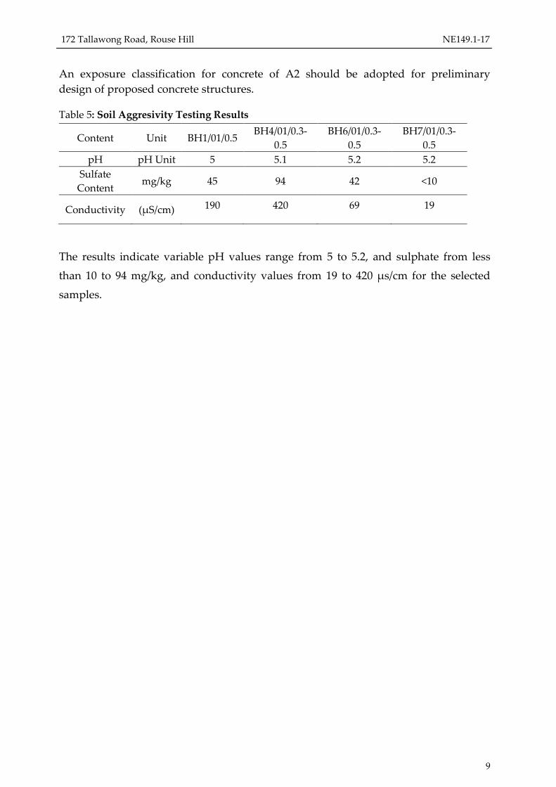
An exposure classification for concrete of A2 should be adopted for preliminary
design of proposed concrete structures.
Table 5: Soil Aggresivity Testing Results
Content Unit BH1/01/0.5 BH4/01/0.3-
0.5
BH6/01/0.3-
0.5
BH7/01/0.3-
0.5
pH pH Unit 5 5.1 5.2 5.2
Sulfate
Content mg/kg 45 94 42 <10
Conductivity (μS/cm) 190 420 69 19
The results indicate variable pH values range from 5 to 5.2, and sulphate from less
than 10 to 94 mg/kg, and conductivity values from 19 to 420 μs/cm for the selected
samples.
172 Tallawong Road, Rouse Hill NE149.1-17
10
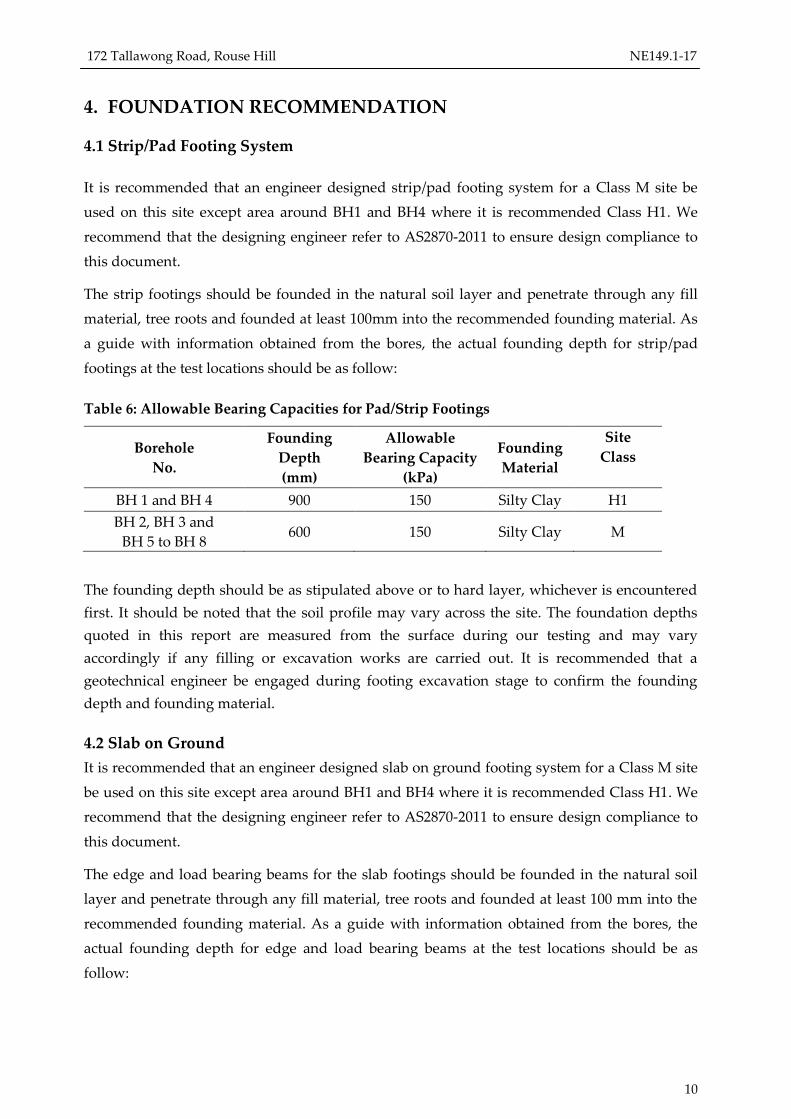
4. FOUNDATION RECOMMENDATION
4.1 Strip/Pad Footing System
It is recommended that an engineer designed strip/pad footing system for a Class M site be
used on this site except area around BH1 and BH4 where it is recommended Class H1. We
recommend that the designing engineer refer to AS2870-2011 to ensure design compliance to
this document.
The strip footings should be founded in the natural soil layer and penetrate through any fill
material, tree roots and founded at least 100mm into the recommended founding material. As
a guide with information obtained from the bores, the actual founding depth for strip/pad
footings at the test locations should be as follow:
Table 6: Allowable Bearing Capacities for Pad/Strip Footings
Borehole
No.
Founding
Depth
(mm)
Allowable
Bearing Capacity
(kPa)
Founding
Material
Site
Class
BH 1 and BH 4 900 150 Silty Clay H1
BH 2, BH 3 and
BH 5 to BH 8 600 150 Silty Clay M
The founding depth should be as stipulated above or to hard layer, whichever is encountered
first. It should be noted that the soil profile may vary across the site. The foundation depths
quoted in this report are measured from the surface during our testing and may vary
accordingly if any filling or excavation works are carried out. It is recommended that a
geotechnical engineer be engaged during footing excavation stage to confirm the founding
depth and founding material.
4.2 Slab on Ground
It is recommended that an engineer designed slab on ground footing system for a Class M site
be used on this site except area around BH1 and BH4 where it is recommended Class H1. We
recommend that the designing engineer refer to AS2870-2011 to ensure design compliance to
this document.
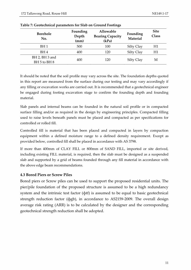
The edge and load bearing beams for the slab footings should be founded in the natural soil
layer and penetrate through any fill material, tree roots and founded at least 100 mm into the
recommended founding material. As a guide with information obtained from the bores, the
actual founding depth for edge and load bearing beams at the test locations should be as
follow:
172 Tallawong Road, Rouse Hill NE149.1-17
11
Table 7: Geotechnical parameters for Slab on Ground Footings
Borehole
No.
Founding
Depth
(mm)
Allowable
Bearing Capacity
(kPa)
Founding
Material
Site
Class
BH 1 500 100 Silty Clay H1
BH 4 400 120 Silty Clay H1
BH 2, BH 3 and
BH 5 to BH 8 400 120 Silty Clay M
It should be noted that the soil profile may vary across the site. The foundation depths quoted
in this report are measured from the surface during our testing and may vary accordingly if
any filling or excavation works are carried out. It is recommended that a geotechnical engineer
be engaged during footing excavation stage to confirm the founding depth and founding
material.
Slab panels and internal beams can be founded in the natural soil profile or in compacted
surface filling and/or as required in the design by engineering principles. Compacted filling
used to raise levels beneath panels must be placed and compacted as per specifications for
controlled or rolled fill.
Controlled fill is material that has been placed and compacted in layers by compaction
equipment within a defined moisture range to a defined density requirement. Except as
provided below, controlled fill shall be placed in accordance with AS 3798.
If more than 400mm of CLAY FILL or 800mm of SAND FILL, imported or site derived,
including existing FILL material, is required, then the slab must be designed as a suspended
slab and supported by a grid of beams founded through any fill material in accordance with
the above edge beam recommendations.
4.3 Bored Piers or Screw Piles
Bored piers or Screw piles can be used to support the proposed residential units. The
pier/pile foundation of the proposed structure is assumed to be a high redundancy
system and the intrinsic test factor (фtf) is assumed to be equal to basic geotechnical
strength reduction factor (фgb), in accordance to AS2159-2009. The overall design
average risk rating (ARR) is to be calculated by the designer and the corresponding
geotechnical strength reduction shall be adopted.
172 Tallawong Road, Rouse Hill NE149.1-17
12
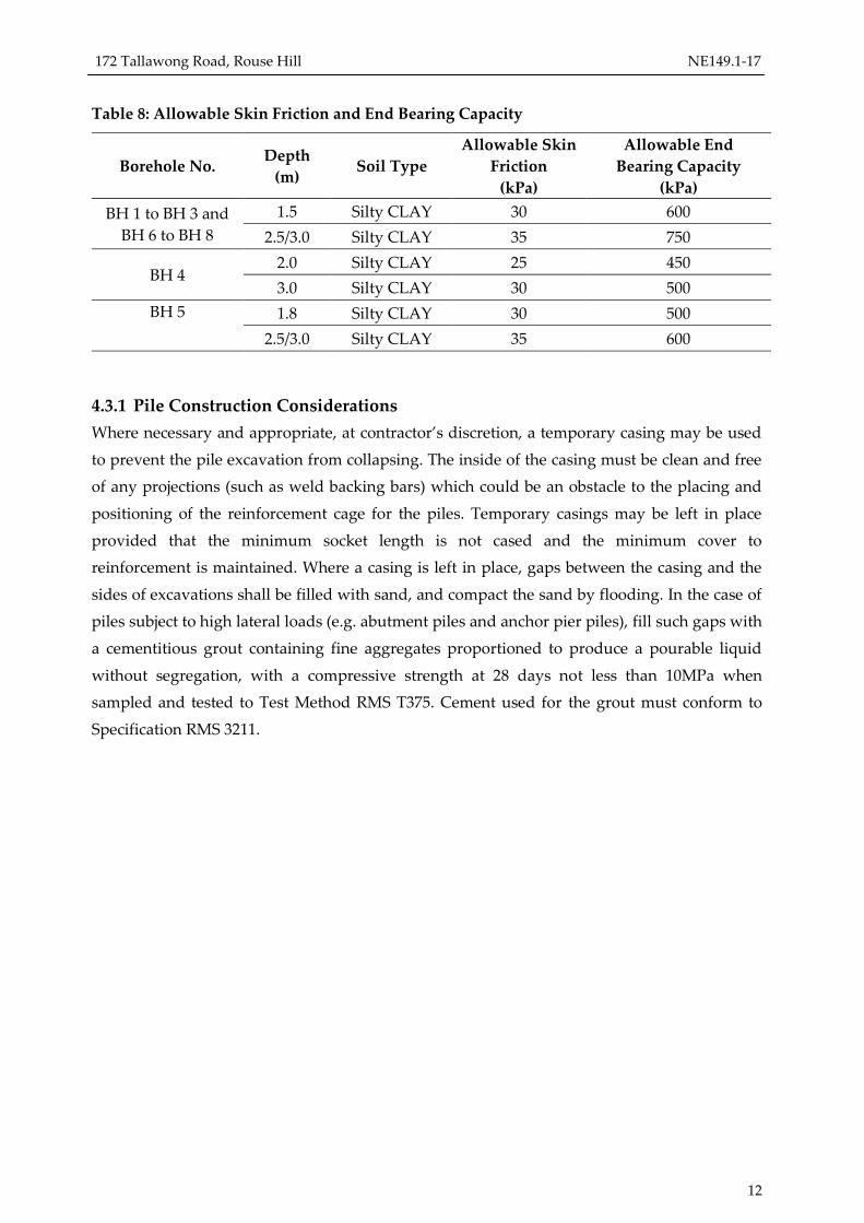
Table 8: Allowable Skin Friction and End Bearing Capacity
Borehole No. Depth
(m) Soil Type
Allowable Skin
Friction
(kPa)
Allowable End
Bearing Capacity
(kPa)
BH 1 to BH 3 and
BH 6 to BH 8
1.5 Silty CLAY 30 600
2.5/3.0 Silty CLAY 35 750
BH 4 2.0 Silty CLAY 25 450
3.0 Silty CLAY 30 500
BH 5 1.8 Silty CLAY 30 500
2.5/3.0 Silty CLAY 35 600
4.3.1 Pile Construction Considerations
Where necessary and appropriate, at contractor’s discretion, a temporary casing may be used
to prevent the pile excavation from collapsing. The inside of the casing must be clean and free
of any projections (such as weld backing bars) which could be an obstacle to the placing and
positioning of the reinforcement cage for the piles. Temporary casings may be left in place
provided that the minimum socket length is not cased and the minimum cover to
reinforcement is maintained. Where a casing is left in place, gaps between the casing and the
sides of excavations shall be filled with sand, and compact the sand by flooding. In the case of
piles subject to high lateral loads (e.g. abutment piles and anchor pier piles), fill such gaps with
a cementitious grout containing fine aggregates proportioned to produce a pourable liquid
without segregation, with a compressive strength at 28 days not less than 10MPa when
sampled and tested to Test Method RMS T375. Cement used for the grout must conform to
Specification RMS 3211.

172 Tallawong Road, Rouse Hill NE149.1-17
13
5. EXCAVATION, RETAINING WALL & LATERAL EARTH
PRESSURES
5.1 Temporary Cut Batter and Excavation
Excavation in the stiff to very stiff silty clay can be undertaken to 1.0m depth without battering
back. While for an excavation deeper than 1.0m, the cut batter should be no steeper than 1H:
1V. The above recommendations are based on the assumption that there is no existing
structure adjacent to the excavation area. Even at the above cut batters it should be noted that
following rainy periods, some degree of fretting and minor slumping could be anticipated.
Soft to Intermediate excavation conditions are anticipated beneath the site at boreholes BH1
and BH4 locations. At boreholes BH2, BH3, BH5, BH6, intermediate to hard excavation
condition is expected below approximately 1.0m depth due to the presence of hard clay with
rock fragments. At boreholes BH7 and BH8, hard excavation condition is expected below
approximately 1.0m depth due to the presence of hard clay with rock fragments/EW-HW rock.
The table below describes the excavation classes as per SANS 1200D.
Excavation Class Description
Soft Excavation in material that can be efficiently removed by a back-acting excavator
of flywheel power approximately 0.10kW per millimetre of tined-bucket width,
without the use of pneumatic tools such as paving breakers
Intermediate Excavation in material that requires a back-acting excavator of flywheel power
exceeding 0.10 kW per millimetre of tined-bucket width or the use of pneumatic
tools before removal by equipment equivalent to that specified for soft excavation.
Hard Hard rock excavation shall be excavation in material (excluding boulder
excavation) that cannot be efficiently removed without blasting or wedging and
splitting.
5.3 Lateral Earth Pressures
For minimum wall deflection, and for construction methods where restraint is applied via
struts, bracing or anchors, the temporary or short-term lateral earth pressure distribution
should approximate a trapezoidal distribution, in which a maximum pressure of 10H kPa is
obtained at a depth of 0.25H, and where H is the total depth of the excavation to be retained.
For basement walls, where wall deflections are not critical, the maximum pressure may be
reduced to 6H kPa.
The above parameters assume that the drained situation exists and that any adjacent surcharge
loading be superimposed using an “at rest” earth pressure coefficient (Ko) of 0.57. It is
emphasised that where adjoining footings exist, the “at rest” pressures must be maintained
and the active design condition is not appropriate.

172 Tallawong Road, Rouse Hill NE149.1-17
14
The lateral earth pressures can be estimated by adopting the following soil parameters, for
retaining walls where the active earth pressure condition is permitted to be mobilised.
Table 9: Materials Strength Parameters
Borehol
e
No.
Depth
(m) Soil/Rock Type
Unit
Weight
(kN/m3)
Cohesion
c’
(kPa)
Friction
Angle
(°)
BH 1
0-0.5 Fill 19 - 28
0.5-1.0 Silty CLAY 18 5 25
1.0-1.5 Silty CLAY 18 5 27
1.5-2.0 Silty CLAY 18 10 27
2.0-3.0 Silty CLAY with Shale
fragments 19 12 28
BH 2
0-0.3 Fill 19 - 28
0.3-0.8 Silty CLAY 18 5 27
0.8-0.85 Silty CLAY 18 10 27
BH 3
0-0.3 Fill 19 - 28
0.3-1.2 Silty CLAY 18 5 27
1.2-1.35 Silty CLAY 19 10 28
BH 4
0-0.2 Fill 19 - 28
0.2-2.0 Silty CLAY 18 5 27
2.0-4.0 Silty CLAY 18 7 27
4.0-4.5 Silty CLAY 19 10 28
BH 5
0-0.3 Fill 19 - 28
0.3-1.7 Silty CLAY 18 10 27
1.7-2.4 Silty CLAY with Shale
fragments 19 12 28
BH 6 0-1.2 Silty CLAY 18 5 27
1.2-1.35 Silty CLAY 19 10 28
BH 7 0-0.50 Silty CLAY 18 5 27
0.5-0.6 Silty CLAY 19 10 28
BH 8
0-0.50 Silty CLAY 18 5 27
0.5-0.8 Silty CLAY 18 10 27
0.8-4.0 Silty CLAY 19 10 28
Note: c’=effective cohesion; ’=effective angle of friction
5.4 Anchored Soldier Pile Retention Systems
The use of anchored secant or contiguous piles can be adopted for this site. In considering
such a retention system, the following aspects should be taken into account in the design and
construction of the proposed retaining walls:
172 Tallawong Road, Rouse Hill NE149.1-17
15
The anchors should be considered with earth pressure “at rest” condition as the
design criteria.
Additional reinforced Shotcrete layer should be applied to all the exposed faces of the
basement excavation prior to the next level of excavation. Shotcrete should be applied
before the bulk excavation exceeds a depth of approximately 1.0 meters. However,
this may require review once the levels of adjoining footings are known.
Excavation for the basement level should not extend more than 0.5 meters below the
level of the ground anchors if they are used to maintain at rest earth pressures before
the anchors are installed and fully pre-stressed.
5.5 Ground Anchors
Ground anchors used in connection with the temporary support of any retention structures
should extend into stiff to very stiff silty clay, with the design being based on a grout/ground
bond strength of 10kPa (drilled using air flush or auger methods) above the ground water
table.
The free length of ground anchors should be sufficient to ensure that failure cannot occur on a
sliding wedge behind the retention wall structures. As a guide it is therefore recommended
that the free length of the ground anchors should extend at least 1.5m beyond the 45˚ line
extending from the base of the basement excavation.
Generally, ground anchors should be installed at an angle of approximately 15˚ to 20˚ below
the horizontal and where possible the ground anchor bond length should not exceed 12m to
ensure adequate load transfer characteristics.
5.6 Estimated Wall Deflections and Ground Settlements
It is recommended that the proposed ground anchors be given sufficient capacity such that
additional stress can be applied throughout the construction sequence to limit wall deflections,
as required, based on regular monitoring of wall deflections. In addition, the depth to the top
row of anchors should not be greater than 1.5m below the ground surface level.
The maximum wall deflection is estimated to lie in the range between 0.25% and 0.35% of the
excavation depth. Corresponding vertical settlements of between 0.20% and 0.25% of the
excavation depth can be anticipated directly behind the wall, with settlements reducing to
zero at a lateral distance approximately corresponding to the depth of the basement
excavation. When considering the influence of the anticipated settlements on the existing
adjoining structures, the founding depths of the existing footings should be taken into account.
In addition to the inherent deformations which will take place within the proposed basement
excavation, there may be some minor delays between excavation and the establishment of a
suitable anchoring arrangement, during which time additional minor lateral deflection may
172 Tallawong Road, Rouse Hill NE149.1-17
16
take place. A full dilapidation survey of any adjoining structures is therefore recommended
prior to the commencement of the basement excavation. This should be followed by regular
survey and monitoring during construction.
5.7 Drainage of Retention Systems
As seepage infiltration from perched water table is quite likely to be present in the zones of
influence during wet season, it is recommended that a suitable drainage system be installed
and maintained behind all retaining wall structures to ensure the dissipation of any
hydrostatic forces which may result from the accumulation of any seepage water behind the
wall structures. Such seepage water flows should readily be able to be intercepted by the
construction of a suitable sub-surface cut-off drain on the high side of the subject site.
If the groundwater is encountered, then the earth retaining wall system should be designed as
either an impermeable tank system with installation of contiguous piles or secant piles and
additional impervious layer to prevent groundwater flow into the basement.
5.8 Basement Floor Construction
Provided that the basement excavation does not intersect the groundwater table and no
hydrostatic pressures will be generated on the underside of the basement floor, the use of a
conventional concrete ground slab should perform satisfactorily in relation to the proposed
utilisation. Such floor slabs should be constructed on stiff to very stiff silty clay subgrade at the
proposed basement level and may be designed using a Modulus of Subgrade reaction of
55kPa/mm. Under-slab drainage should be provided to the basement to prevent hydrostatic
build-up in the event of rising ground water.
Preparation of the basement floor subgrade should consist of stripping to grade and proof
rolling the subgrade, ensuring that any localised soft spots are removed and made good with
clean granular filling compacted to a dry density not less than 98% of the maximum dry
density value determined by the Standard Compaction test in accordance with Australian
Standard AS1289 5.11 – 1993.
A suitable dewatering system (spears or sump pump) may be required to pump groundwater
in the event that the groundwater is encountered above the basement level. Although
groundwater was not encountered during the geotechnical investigation, the presence of
perched groundwater resulted from infiltration of surface run-off should not be dismissed.

172 Tallawong Road, Rouse Hill NE149.1-17
17
DOCUMENT CONTROL
Date Version Report Prepared By: Report Reviewed by:
31 May 2017 NE149.1-17 Yogesh Pindoliya
BEng MEng MIEAust
Geotechnical Engineer
Amir Farazmand
BEng MEng MIEAust CPEng
Senior Geotechnical Engineer
172 Tallawong Road, Rouse Hill NE149.1-17
18
6. REFERENCES
Australian Standard (1993), Geotechnical Site Investigations (AS1726).
Australian Standard (2009), Piling - Design and Installation (AS2159).
Australian Standard (2002), Earth-retaining Structures (AS4678).
Australian Standard (2004), Bridge Design Part 5: Concrete (AS5100.5).
Pells, P.J.N., Mostyn, G., Walker, B.F. (1998) Design Loadings for Foundations on Shale and
Sandstone in the Sydney Region.
National Environment Protection Council, December 1999. National Environment
Protection (Assessment of Site Contamination) Measure.
NSW Environment Protection Authority, December 1994. Guidelines for Assessing Service
Station Sites
Australian Standard AS 3600: 2009, Concrete Structures
Department of Land and Water Conservation (DLWC, 2002) Site investigations for urban
salinity.
CSIRO BTF 18 (2003) Foundation Maintenance and Footing Performance: A homeowner’s
Guide.
Department of Infrastructure Planning and Natural Resources (DIPNR, 2002) Salinity
Potential in Western Sydney Map.
Western Sydney Regional Organisation of Councils (WSROC, 2003) Western Sydney
Salinity Code of Practice.
172 Tallawong Road, Rouse Hill NE149.1-17
19
Information about This Report
The report contains the results of Soil and water quality Assessment conducted for a specific
purpose and client. The results should not be used by other parties, or for other purposes, as
they may contain neither adequate nor appropriate information.
Test Hole Logging
The information on the test hole logs (boreholes, test pits, exposures etc.) is based on a visual
and tactile assessment, except at the discrete locations where test information is available (field
and/or laboratory results). The test hole logs include both factual data and inferred
information.
Groundwater
Unless otherwise indicated, the water levels presented on the test hole logs are the levels of
free water or seepage in the test hole recorded at the given time of measuring. The actual
groundwater level may differ from this recorded level depending on material permeability
(i.e. depending on response time of the measuring instrument). Further, variations of this level
could occur with time due to such effects as seasonal, environmental and tidal fluctuations or
construction activities. Confirmation of groundwater levels, pheratic surfaces or piezometric
pressures can only be made by appropriate instrumentation techniques and monitoring
programmes.
Interpretation of Results
The discussion or recommendations contained within this report normally are based on a site
evaluation from discrete test hole data. Generalised, idealised or inferred subsurface
conditions (including any geotechnical cross-sections) have been assumed or prepared by
interpolation and/or extrapolation of these data. As such these conditions are an interpretation
and must be considered as a guide only.
Change in Conditions
Local variations or anomalies in the generalised ground conditions do occur in the natural
environment, particularly between discrete test hole locations. Additionally, certain design or
construction procedures may have been assumed in assessing the soil-structure interaction
behaviour of the site. Furthermore, conditions may change at the site from those encountered
at the time of the geotechnical investigation through construction activities and constantly
changing natural forces.
Any change in design, in construction methods, or in ground conditions as noted during
construction, from those assumed or reported should be referred to GEOTESTA for
appropriate assessment and comment.
Reproduction of Reports
Where it is desired to reproduce the information contained in our geotechnical report, or other
technical information, for the inclusion in contract documents or engineering specification of
the subject development, such reproductions should include at least all of the relevant test
hole and test data, together with the appropriate standard description sheets and remarks
made in the written report of a factual or descriptive nature. Reports are the subject of
copyright and shall not be reproduced without the permission of Geotesta.

172 Tallawong Road, Rouse Hill NE149.1-17
20
SITE PHOTOGRAPHS
Location of borehole BH1
Location of borehole BH2
172 Tallawong Road, Rouse Hill NE149.1-17
21
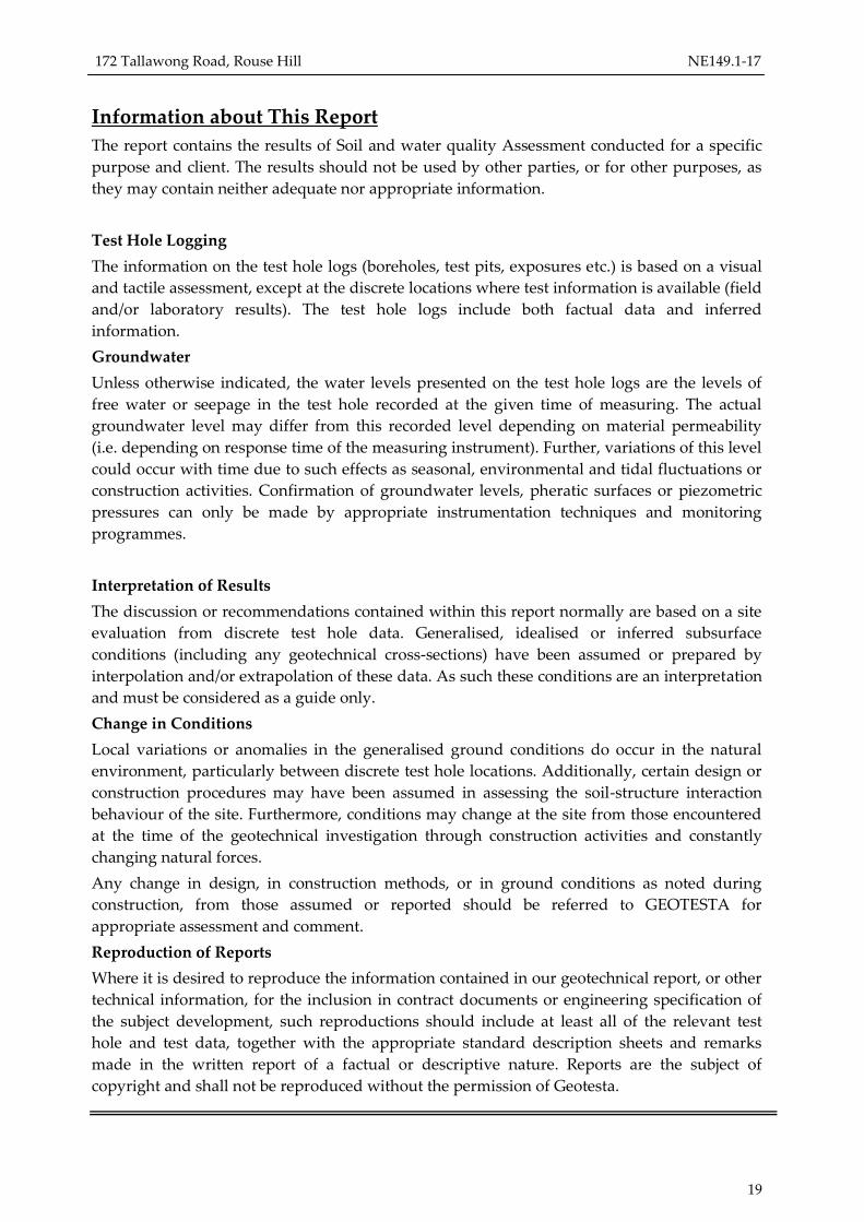
Location of borehole BH3
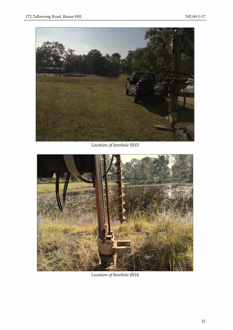
Location of borehole BH4
172 Tallawong Road, Rouse Hill NE149.1-17
22
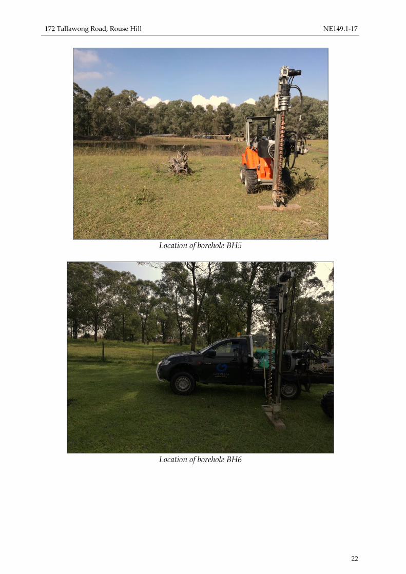
Location of borehole BH5
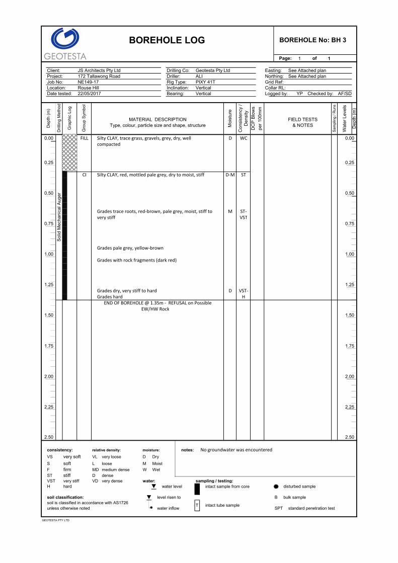
Location of borehole BH6

172 Tallawong Road, Rouse Hill NE149.1-17
23
Location of borehole BH7
Location of borehole BH8

172 Tallawong Road, Rouse Hill NE149.1-17
24
Appendix A
Borehole Logs

Page: 1 of 1
Client: Drilling Co:Project: Driller:Job No: Rig Type:Location: Inclination:Date Drilled: Bearing: Checked by:
consistency: relative density: moisture: Notes:
VS very soft VL very loose D Dry
S soft L loose M Moist No groundwater was encounteredF firm MD medium dense W Wet Disturbed SampleST stiff D dense S SaturatedVST very stiff VD very dense water: sampling / testing:H hard water level intact sample from core Standard Penetration Test
soil classification: level risen to B Bulk samplesoil is classified in accordance with AS1726 Supp Su from Pocket Penetrometerunless otherwise noted water inflow Suv Su from Field Vane Shear test
BOREHOLE LOG BOREHOLE No: BH 1
JS Architects Pty Ltd Geotesta Pty Ltd Easting: See attached Plan172 Tallawong Road Ali Northing: See attached PlanNE149-17 PIXY 41T Grid Ref:Rouse Hill Vertical Collar RL:22/05/2017 Vertical Logged by: YP AF/SD
Test Method: AS 1289.6.3.2-1997 & AS 1726-1993
De
pth
(m)
Dri
llin
g M
etho
d
Gra
phic
Log
Gro
up S
ymb
ol
Moi
stu
re
Co
nsis
ten
cy /
Str
eng
th
DC
Pbl
ows/
100m
m
Sam
plin
g /
Run
s
Wat
er L
eve
ls
De
pth
(m)
MATERIAL DESCRIPTION FIELD TESTSType, colour, particle size and shape, structure & NOTES
0.00 FILL Silty CLAY, trace of gravel, brick pieces, concrete D-M WC 8 0.00rubbles, grey, brown, dry to moist, well compacted 15
148
0.50 8 0.50CI Silty CLAY, red, pale grey, moist, firm M F 3
323
1.00 3 1.00Grades, trace rock fragments, pale grey, red-brown, ST- 4stiff to very stiff 8Grades trace tree roots 8
91.50 9 1.50
Grades pale grey, red-brown, mottled yellow-brown D-M H 13dry to moist, hard 14
15
2.00 2.00Grades trace of shale fragments (dark grey, brown, red)
2.50 2.50Grades with shale fragments
3.00 3.00END OF BOREHOLE @ 3.0m
3.50 3.50
4.00 4.00
4.504.50
5.00
T intact tube sample
So
lid M
ech
an
ica
l Au
ge
r VST
GEOTESTA PTY LTD
5.00

Page: 1 of 1
Client: Drilling Co: Easting:Project: Mckimmies Road, Mill Park Driller: Northing:Job No: Rig Type: Grid Ref:Location: Inclination: Collar RL:Date tested: Bearing: Logged by: Checked by:
compacted
consistency: relative density: moisture: notes: No groundwater was encounteredVS very soft VL very loose D Dry Disturbed SampleS soft L loose M Moist X denotes effective refusal (>15/50mm) - bounces of DCP hammerF firm MD medium dense W Wet
ST stiff D denseVST very stiff VD very dense water: sampling / testing:H hard water level intact sample from core disturbed sample
soil classification: level risen to B bulk samplesoil is classified in accordance with AS1726unless otherwise noted water inflow SPT standard penetration test
JS Architects Pty Ltd Geotesta Pty Ltd See Attached plan
BOREHOLE No: BH 2BOREHOLE LOG
172 Tallawong Road ALI See Attached planNE149-17 PIXY 41TRouse Hill Vertical22/05/2017 Vertical YP AF/SD
Sam
plin
g /
Run
s
Wat
er L
eve
ls
De
pth
(m
)
Dri
llin
g M
eth
od
Gra
ph
ic L
og
Gro
up
Sym
bo
l
Moi
stur
e
Co
nsis
tenc
y /
De
nsity
per
100m
m
De
pth
(m
)
MATERIAL DESCRIPTION FIELD TESTSType, colour, particle size and shape, structure & NOTES
0.00 FILL M
DC
P B
low
s
WC 5 0.00Silty CLAY, trace grass, gravels, grey, moist, well
6
0.25 6 0.25
CI Silty CLAY, red, moist, stiff M ST 4
0.50Grades red-brown, pale grey, dry to moist, very stiff D-M VST 9
6Grades with rock fragments (dark red)
40.50
0.75 8
Sol
id M
echa
nica
l Aug
er
X
0.75
Grades hard H
EW/HW RockEND OF BOREHOLE @ 0.85m - REFUSAL on Possible
1.00 1.00
1.25 1.25
1.50 1.50
1.75 1.75
2.00 2.00
2.25
2.50
T intact tube sample
GEOTESTA PTY LTD
2.50
2.25
Page: 1 of 1
Client: Drilling Co: Easting:Project: Mckimmies Road, Mill Park Driller: Northing:Job No: Rig Type: Grid Ref:Location: Inclination: Collar RL:Date tested: Bearing: Logged by: Checked by:
consistency: relative density: moisture: notes: No groundwater was encounteredVS very soft VL very loose D Dry
S soft L loose M Moist
F firm MD medium dense W WetST stiff D denseVST very stiff VD very dense water: sampling / testing:H hard water level intact sample from core disturbed sample
soil classification: level risen to B bulk samplesoil is classified in accordance with AS1726unless otherwise noted water inflow SPT standard penetration test
END OF BOREHOLE @ 1.35m - REFUSAL on Possible
compacted
very stiff
BOREHOLE LOG BOREHOLE No: BH 3
NE149-17 PIXY 41T
Co
nsis
tenc
y /
De
nsity
JS Architects Pty Ltd Geotesta Pty Ltd See Attached plan172 Tallawong Road ALI See Attached plan
Rouse Hill Vertical22/05/2017 Vertical YP AF/SD
per
100m
m
Sam
plin
g /
Run
s
Wat
er L
eve
ls
De
pth
(m
)
Dri
llin
g M
eth
od
Gra
ph
ic L
og
Gro
up
Sym
bo
l
Moi
stur
e
De
pth
(m
)
MATERIAL DESCRIPTION FIELD TESTSType, colour, particle size and shape, structure & NOTES
0.00 FILL Silty CLAY, trace grass, gravels, grey, dry, well D
DC
P B
low
s
WC 0.00
ST
0.25 0.25
CI Silty CLAY, red, mottled pale grey, dry to moist, stiff D-M
0.50 0.50
Grades trace roots, red-brown, pale grey, moist, stiff to M ST-
Grades with rock fragments (dark red)
VST0.75 0.75
Grades pale grey, yellow-brown1.00 1.00
H
1.25
Grades hard
1.25Grades dry, very stiff to hard D VST-
1.50EW/HW Rock
1.50
1.75 1.75
2.00 2.00
2.252.25
2.50
T intact tube sample
GEOTESTA PTY LTD
Sol
id M
echa
nica
l Aug
er
2.50
Page: 1 of 1
Client: Drilling Co:Project: Driller:Job No: Rig Type:Location: Inclination:Date Drilled: Bearing: Checked by:
consistency: relative density: moisture: Notes:
VS very soft VL very loose D Dry
S soft L loose M Moist No groundwater was encounteredF firm MD medium dense W Wet Disturbed SampleST stiff D dense S SaturatedVST very stiff VD very dense water: sampling / testing:H hard water level intact sample from core Standard Penetration Test
soil classification: level risen to B Bulk samplesoil is classified in accordance with AS1726 Supp Su from Pocket Penetrometerunless otherwise noted water inflow Suv Su from Field Vane Shear test
GEOTESTA PTY LTD
CI M
So
lid M
ech
an
ica
l Au
ge
r
Grades red-brown, dark grey, stiff
stiff
Grades pale grey, red-brown, dry to moist, very stiff to D-M
5.00 5.00
T intact tube sample
END OF BOREHOLE @ 4.5m4.50 4.50
4.00 VST- 4.00hard H
3.50 3.50
3.00 3.00
2.50 2.50
red-brown, dark grey, mottled orange-brown, very
2.00Grades trace of rock fragments (dark grey, brown, red), VST
62.00 6
65
1.50 ST 4 1.506
F 333
1.00Grades, pale grey, red-brown 5
51.00 4
56
0.504
ST 63
0.50 4
WC 4 0.00grey, dry to moist, well compacted 4
0.00 FILL Silty CLAY, trace fine gravel, grass roots, grey to brown- D-M
Silty CLAY, red, pale grey, moist, stiff
Wat
er L
eve
ls
De
pth
(m)
MATERIAL DESCRIPTION FIELD TESTSType, colour, particle size and shape, structure & NOTES
Test Method: AS 1289.6.3.2-1997 & AS 1726-1993
De
pth
(m)
Dri
llin
g M
etho
d
Gra
phic
Log
Gro
up S
ymb
ol
Moi
stu
re
Co
nsis
ten
cy /
Str
eng
th
DC
Pbl
ows/
100m
m
Sam
plin
g /
Run
s
Rouse Hill Vertical Collar RL:22/05/2017 Vertical Logged by: YP AF/SD
172 Tallawong Road Ali Northing: See attached PlanNE149-17 PIXY 41T Grid Ref:
BOREHOLE LOG BOREHOLE No: BH 4
JS Architects Pty Ltd Geotesta Pty Ltd Easting: See attached Plan

Page: 1 of 1
Client: Drilling Co: Easting:Project: Mckimmies Road, Mill Park Driller: Northing:Job No: Rig Type: Grid Ref:Location: Inclination: Collar RL:Date tested: Bearing: Logged by: Checked by:
consistency: relative density: moisture: notes: No groundwater was encounteredVS very soft VL very loose D Dry EW/HW - Extremely/Highly WeatheredS soft L loose M Moist X denotes effective refusal (>15/30mm) - bounces of DCP hammerF firm MD medium dense W WetST stiff D denseVST very stiff VD very dense water: sampling / testing:H hard water level intact sample from core disturbed sample
soil classification: level risen to B bulk samplesoil is classified in accordance with AS1726unless otherwise noted water inflow SPT standard penetration test
GEOTESTA PTY LTD
5
7
X
Sol
id M
echa
nica
l Aug
er
END OF BOREHOLE @ 2.4m - REFUSAL on Possible
dry to moist, well compacted
Grades red, grey to pale grey, brown to brown-grey
pale grey, orange-brown, dry, hard
2.50 2.50
T intact tube sample
EW/HW Rock
2.25 2.25
2.00 2.00
1.751.75 D H 13
6
1.50
7
61.50
ST-VST
Grades pale grey, red, stiff to very stiff
1.251.25 6
6
1.00
Grades with shale fragments (dark red), brown,
6
51.00
0.75
Grades red, pale grey
0.75 5
5
0.50
5
50.50
0.25
CI Silty CLAY, trace rock fragments, red-brown, moist, stiff M ST 6
0.25 9
10
WC 5 0.00
De
pth
(m
)
MATERIAL DESCRIPTION FIELD TESTSType, colour, particle size and shape, structure & NOTES
0.00 FILL Silty CLAY, trace grass, gravels, brown to grey-brown, D-M
DC
P B
low
s
Sam
plin
g /
Run
s
Wat
er L
eve
ls
De
pth
(m
)
Dri
llin
g M
eth
od
Gra
ph
ic L
og
Gro
up
Sym
bo
l
Moi
stur
e
Co
nsis
tenc
y /
De
nsity
Rouse Hill Vertical22/05/2017 Vertical YP AF/SD
per
100m
m
172 Tallawong Road ALI See Attached planNE149-17 PIXY 41T
BOREHOLE LOG BOREHOLE No: BH 5
JS Architects Pty Ltd Geotesta Pty Ltd See Attached plan
Page: 1 of 1
Client: Drilling Co: Easting:Project: Mckimmies Road, Mill Park Driller: Northing:Job No: Rig Type: Grid Ref:Location: Inclination: Collar RL:Date tested: Bearing: Logged by: Checked by:
consistency: relative density: moisture: notes: No groundwater was encounteredVS very soft VL very loose D Dry
S soft L loose M Moist
F firm MD medium dense W WetST stiff D denseVST very stiff VD very dense water: sampling / testing:H hard water level intact sample from core disturbed sample
soil classification: level risen to B bulk samplesoil is classified in accordance with AS1726unless otherwise noted water inflow SPT standard penetration test
GEOTESTA PTY LTD
2.50 2.50
T intact tube sample
2.25 2.25
2.00 2.00
1.751.75
1.50EW/HW Rock
1.50
Grades grey, brown, red, hard HEND OF BOREHOLE @ 1.35m - REFUSAL on Possible
1.25H
1.25 Grades dry, very stiff to hard D VST-
1.001.00
Grades pale grey, red, orange-brown, dry to moist D-M
0.75
Grades trace rock fragments (dark red), very stiff VST
0.75
Grades red-brown, pale grey, stiff to very stiff ST-VST
0.500.50
0.25
Grades red-brown
0.25
ST 0.00
De
pth
(m
)
MATERIAL DESCRIPTION FIELD TESTSType, colour, particle size and shape, structure & NOTES
0.00
Sol
id M
echa
nica
l Aug
er
CI Silty CLAY, trace grass, grey to grey-brown, moist, stiff M
DC
P B
low
s
per
100m
m
Sam
plin
g /
Run
s
Wat
er L
eve
ls
De
pth
(m
)
Dri
llin
g M
eth
od
Gra
ph
ic L
og
Gro
up
Sym
bo
l
Moi
stur
e
Co
nsis
tenc
y /
De
nsity
Rouse Hill Vertical22/05/2017 Vertical YP AF/SD
172 Tallawong Road ALI See Attached planNE149-17 PIXY 41T
BOREHOLE LOG BOREHOLE No: BH 6
JS Architects Pty Ltd Geotesta Pty Ltd See Attached plan
Page: 1 of 1
Client: Drilling Co: Easting:Project: Mckimmies Road, Mill Park Driller: Northing:Job No: Rig Type: Grid Ref:Location: Inclination: Collar RL:Date tested: Bearing: Logged by: Checked by:
consistency: relative density: moisture: notes: No groundwater was encounteredVS very soft VL very loose D Dry Disturbed SampleS soft L loose M Moist X denotes effective refusal (>15/50mm) - bounces of DCP hammerF firm MD medium dense W Wet
ST stiff D denseVST very stiff VD very dense water: sampling / testing:H hard water level intact sample from core disturbed sample
soil classification: level risen to B bulk samplesoil is classified in accordance with AS1726unless otherwise noted water inflow SPT standard penetration test
GEOTESTA PTY LTD
Sol
id M
echa
nica
l Aug
er
END OF BOREHOLE @ 0.6m - REFUSAL on PossibleD H
2.50 2.50
T intact tube sample
2.25 2.25
2.00 2.00
1.751.75
1.501.50
1.251.25
1.001.00
0.750.75EW/HW Rock
0.50
Grades brown, red, dry, hard
0.50
moist, stiff to very stiff VST
0.25
Grades trace rock fragments, red-brown, orange-brown, ST-
0.25Grades stiff ST
F 0.00
De
pth
(m
)
MATERIAL DESCRIPTION FIELD TESTSType, colour, particle size and shape, structure & NOTES
0.00 CI Silty CLAY, trace grass, grey to gey-brown, moist, firm M
DC
P B
low
s
Sam
plin
g /
Run
s
Wat
er L
eve
ls
De
pth
(m
)
Dri
llin
g M
eth
od
Gra
ph
ic L
og
Gro
up
Sym
bo
l
Moi
stur
e
Co
nsis
tenc
y /
De
nsity
Rouse Hill Vertical22/05/2017 Vertical YP AF/SD
per
100m
m
172 Tallawong Road ALI See Attached planNE149-17 PIXY 41T
BOREHOLE LOG BOREHOLE No: BH 7
JS Architects Pty Ltd Geotesta Pty Ltd See Attached plan

Page: 1 of 1
Client: Drilling Co:Project: Driller:Job No: Rig Type:Location: Inclination:Date Drilled: Bearing: Checked by:
consistency: relative density: moisture: Notes:
VS very soft VL very loose D Dry X denotes effective refusal (>15/50mm) - bounces of DCP hammerS soft L loose M Moist No groundwater was encounteredF firm MD medium dense W Wet Disturbed SampleST stiff D dense S SaturatedVST very stiff VD very dense water: sampling / testing:H hard water level intact sample from core Standard Penetration Test
soil classification: level risen to B Bulk samplesoil is classified in accordance with AS1726 Supp Su from Pocket Penetrometerunless otherwise noted water inflow Suv Su from Field Vane Shear test
GEOTESTA PTY LTD
So
lid M
ech
an
ica
l Au
ge
r
VSTD-M
5.00 5.00
T intact tube sample
4.504.50
END OF BOREHOLE @ 4.0m4.00 4.00
Grades grey3.50 3.50
Grades with shale frgaments (EW/HW)3.00 3.00
red-brown, pale grey, dry
2.50 2.50Grades trace shale fragments (dark grey, dark red), D
2.00 2.00Grades brown, pale grey, red-brown
1.00
1.50 1.50
Grades hard H X11
Grades, pale grey to gey, red-brown to brown
yellow-brown, dry to moist, very stiff 10
1.00
9
0.50 Grades trace rock fragments, pale grey, brown to 7 0.50
VST 766
0.00 CI Silty CLAY, trace fine gravel, grass roots, grey to brown- D-M
Grades red-brown, moist Mgrey, dry to moist, stiff to very stiff
Wat
er L
eve
ls
De
pth
(m)
MATERIAL DESCRIPTION FIELD TESTSType, colour, particle size and shape, structure & NOTES
ST- 8 0.00
Test Method: AS 1289.6.3.2-1997 & AS 1726-1993
De
pth
(m)
Dri
lling
Met
hod
Gra
phic
Log
Gro
up S
ymb
ol
Moi
stu
re
Co
nsis
ten
cy /
Str
eng
th
DC
Pbl
ows/
100m
m
Sam
plin
g /
Run
s
Rouse Hill Vertical Collar RL:22/05/2017 Vertical Logged by: YP AF/SD
172 Tallawong Road Ali Northing: See attached PlanNE149-17 PIXY 41T Grid Ref:
BOREHOLE LOG BOREHOLE No: BH 8
JS Architects Pty Ltd Geotesta Pty Ltd Easting: See attached Plan

172 Tallawong Road, Rouse Hill NE149.1-17
25
Appendix B
Laboratory Test Results

GEOTESTA Pty Ltd
Plasticity Index & Linear Shrinkage Rock & Soil Mechanics Laboratory
17 Redwood Drive
Notting Hill , Vic 3168
Geotesta Project Contamination Assessment Client JS Architects Pty. Ltd.
L0676-A1 Project No NE149-17 Client ID -
L0676-1 Location 172 Tallawong Road Address 100 Barangaroo Ave
[email protected] Rouse Hill NSW 2155 Sydney , NSW 2000
Results Notes
% History of sample:% Method of preparation:% Linear shrinkage:% Length of mould:
Comments
Test methods: AS 1289, 2.1.1, 3.1.2, 3.2.1, 3.3.1, 3.4.1
AS 1289.1.2.1 CL 6.5.3 - Power auger
Silty Clay, mottled orange-brown and grey, moist
Test Report
Sample Description
Laboratory
Report No
Sample ID
Borehole ID
Atterberg Limits
Report issued by:
Date issued: 1/06/2017
Tests (LL PL PI LS) V5
Rene Kurniadi
15
Sampling Method
Liquid limitPlastic limitPlasticity indexLinear shrinkage
-
Accredited for compliance with ISO/IEC 17025 - Testing
The results of the tests included in this document are traceable to Australian and national standards.
Oven-driedDry-sievedNo Crack
--
Page 1 of 1
200 mm
GEOTESTA Pty Ltd
Plasticity Index & Linear Shrinkage Rock & Soil Mechanics Laboratory
17 Redwood Drive
Notting Hill , Vic 3168
Geotesta Project Contamination Assessment Client JS Architects Pty. Ltd.
L0676-A2 Project No NE149-17 Client ID -
L0676-2 Location 172 Tallawong Road Address 100 Barangaroo Ave
[email protected] Rouse Hill NSW 2155 Sydney , NSW 2000
Results Notes
% History of sample:% Method of preparation:% Linear shrinkage:% Length of mould:
Comments
Test methods: AS 1289, 2.1.1, 3.1.2, 3.2.1, 3.3.1, 3.4.1
AS 1289.1.2.1 CL 6.5.3 - Power auger
Silty Clay, mottled orange-brown and grey, moist
Test Report
Sample Description
Laboratory
Report No
Sample ID
Borehole ID
Atterberg Limits
Report issued by:
Date issued: 1/06/2017
Tests (LL PL PI LS) V5
Rene Kurniadi
21
Sampling Method
Liquid limitPlastic limitPlasticity indexLinear shrinkage
-
Accredited for compliance with ISO/IEC 17025 - Testing
The results of the tests included in this document are traceable to Australian and national standards.
Oven-driedDry-sievedNo Crack
--
Page 1 of 1
250 mm

Certificate of Analysis
Geotesta Pty Ltd (NSW)
44 Mary Parade
Rydalmere
NSW 2116
Attention: Yogesh Pindoliya
Report 547276-S
Project name 172 TALLAWONG RD ROUSE HILL
Project ID NE149
Received Date May 23, 2017
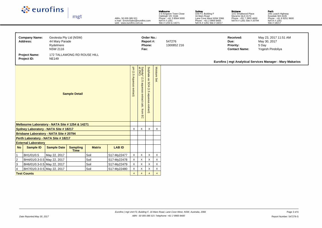
Client Sample ID BH1/01/0.5 BH4/01/0.3-0.5 BH6/01/0.3-0.5 BH7/01/0.3-0.5
Sample Matrix Soil Soil Soil Soil
Eurofins | mgt Sample No. S17-My22477 S17-My22478 S17-My22479 S17-My22480
Date Sampled May 22, 2017 May 22, 2017 May 22, 2017 May 22, 2017
Test/Reference LOR Unit
Conductivity (1:5 aqueous extract at 25°C) 5 uS/cm 190 420 69 19
pH (1:5 Aqueous extract) 0.1 pH Units 5.0 5.1 5.2 5.2
Salinity* (1:5 aqueous extract calc. from EC at 25C) 1 mg/kg 590 1300 250 110
Sulphate as SO4 (1:5 aqueous extract) 10 mg/kg 45 94 42 < 10
% Moisture 1 % 16 15 18 17
Date Reported: May 30, 2017
Eurofins | mgt Unit F3, Building F, 16 Mars Road, Lane Cove West, NSW, Australia, 2066
ABN : 50 005 085 521 Telephone: +61 2 9900 8400
Page 1 of 6
Report Number: 547276-S
NATA AccreditedAccreditation Number 1261Site Number 18217
Accredited for compliance with ISO/IEC 17025 – TestingThe results of the tests, calibrations and/ormeasurements included in this document are traceableto Australian/national standards.

Sample HistoryWhere samples are submitted/analysed over several days, the last date of extraction and analysis is reported.A recent review of our LIMS has resulted in the correction or clarification of some method identifications. Due to this, some of the method reference information on reports has changed. However,no substantive change has been made to our laboratory methods, and as such there is no change in the validity of current or previous results (regarding both quality and NATA accreditation).
If the date and time of sampling are not provided, the Laboratory will not be responsible for compromised results should testing be performed outside the recommended holding time.
Description Testing Site Extracted Holding Time
Conductivity (1:5 aqueous extract at 25°C) Sydney May 29, 2017 7 Day
- Method: LTM-INO-4030
pH (1:5 Aqueous extract) Sydney May 29, 2017 7 Day
- Method: LTM-GEN-7090 pH in soil by ISE
Salinity* (1:5 aqueous extract calc. from EC at 25C) Sydney May 30, 2017 21 Day
- Method: LTM-INO-4030
Sulphate as SO4 (1:5 aqueous extract) Sydney May 30, 2017 28 Day
- Method: APHA 4500-SO4 Sulfate by FIA
% Moisture Sydney May 23, 2017 14 Day
- Method: LTM-GEN-7080 Moisture
Date Reported: May 30, 2017
Eurofins | mgt Unit F3, Building F, 16 Mars Road, Lane Cove West, NSW, Australia, 2066
ABN : 50 005 085 521 Telephone: +61 2 9900 8400
Page 2 of 6
Report Number: 547276-S
.Company Name: Geotesta Pty Ltd (NSW) Order No.: Received: May 23, 2017 11:51 AMAddress: 44 Mary Parade Report #: 547276 Due: May 30, 2017
Rydelmere Phone: 1300852 216 Priority: 5 DayNSW 2116 Fax: Contact Name: Yogesh Pindoliya
Project Name: 172 TALLAWONG RD ROUSE HILLProject ID: NE149
Eurofins | mgt Analytical Services Manager : Mary Makarios
Sample Detail
pH (1:5 A
queous extract)
Salinity* (1:5 aqueous extract calc. from
EC
at 25C)
Sulphate as S
O4 (1:5 aqueous extract)
Moisture S
et
Melbourne Laboratory - NATA Site # 1254 & 14271
Sydney Laboratory - NATA Site # 18217 X X X X
Brisbane Laboratory - NATA Site # 20794
Perth Laboratory - NATA Site # 18217
External Laboratory
No Sample ID Sample Date SamplingTime
Matrix LAB ID
1 BH1/01/0.5 May 22, 2017 Soil S17-My22477 X X X X
2 BH4/01/0.3-0.5 May 22, 2017 Soil S17-My22478 X X X X
3 BH6/01/0.3-0.5 May 22, 2017 Soil S17-My22479 X X X X
4 BH7/01/0.3-0.5 May 22, 2017 Soil S17-My22480 X X X X
Test Counts 4 4 4 4
ABN– 50 005 085 521e.mail : [email protected] : www.eurofins.com.au
MelbourneMelbourneMelbourneMelbourne2-5 Kingston Town CloseOakleigh VIC 3166Phone : +61 3 8564 5000NATA # 1261Site # 1254 & 14271
SydneySydneySydneySydneyUnit F3, Building F16 Mars RoadLane Cove West NSW 2066Phone : +61 2 9900 8400NATA # 1261 Site # 18217
BrisbaneBrisbaneBrisbaneBrisbane1/21 Smallwood PlaceMurarrie QLD 4172Phone : +61 7 3902 4600NATA # 1261 Site # 20794
PerthPerthPerthPerth2/91 Leach HighwayKewdale WA 6105Phone : +61 8 9251 9600NATA # 1261Site # 18217
Date Reported:May 30, 2017
Eurofins | mgt Unit F3, Building F, 16 Mars Road, Lane Cove West, NSW, Australia, 2066
ABN : 50 005 085 521 Telephone: +61 2 9900 8400
Page 3 of 6
Report Number: 547276-S
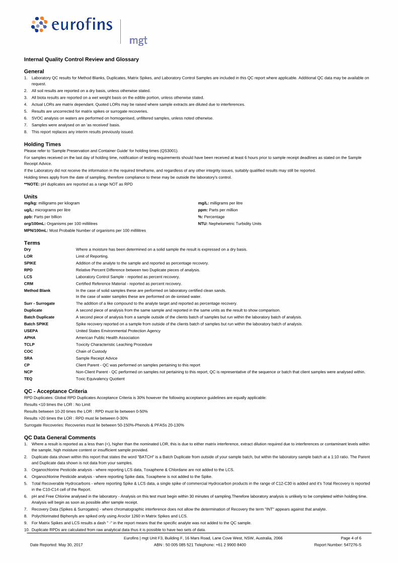
Internal Quality Control Review and Glossary
General
Holding Times
Units
Terms
QC - Acceptance Criteria
QC Data General Comments
1. Laboratory QC results for Method Blanks, Duplicates, Matrix Spikes, and Laboratory Control Samples are included in this QC report where applicable. Additional QC data may be available on
request.
2. All soil results are reported on a dry basis, unless otherwise stated.
3. All biota results are reported on a wet weight basis on the edible portion, unless otherwise stated.
4. Actual LORs are matrix dependant. Quoted LORs may be raised where sample extracts are diluted due to interferences.
5. Results are uncorrected for matrix spikes or surrogate recoveries.
6. SVOC analysis on waters are performed on homogenised, unfiltered samples, unless noted otherwise.
7. Samples were analysed on an 'as received' basis.
8. This report replaces any interim results previously issued.
Please refer to 'Sample Preservation and Container Guide' for holding times (QS3001).
For samples received on the last day of holding time, notification of testing requirements should have been received at least 6 hours prior to sample receipt deadlines as stated on the Sample
Receipt Advice.
If the Laboratory did not receive the information in the required timeframe, and regardless of any other integrity issues, suitably qualified results may still be reported.
Holding times apply from the date of sampling, therefore compliance to these may be outside the laboratory's control.
**NOTE: pH duplicates are reported as a range NOT as RPD
mg/kg: milligrams per kilogram mg/L: milligrams per litre
ug/L: micrograms per litre ppm: Parts per million
ppb: Parts per billion %: Percentage
org/100mL: Organisms per 100 millilitres NTU: Nephelometric Turbidity Units
MPN/100mL: Most Probable Number of organisms per 100 millilitres
Dry Where a moisture has been determined on a solid sample the result is expressed on a dry basis.
LOR Limit of Reporting.
SPIKE Addition of the analyte to the sample and reported as percentage recovery.
RPD Relative Percent Difference between two Duplicate pieces of analysis.
LCS Laboratory Control Sample - reported as percent recovery.
CRM Certified Reference Material - reported as percent recovery.
Method Blank In the case of solid samples these are performed on laboratory certified clean sands.
In the case of water samples these are performed on de-ionised water.
Surr - Surrogate The addition of a like compound to the analyte target and reported as percentage recovery.
Duplicate A second piece of analysis from the same sample and reported in the same units as the result to show comparison.
Batch Duplicate A second piece of analysis from a sample outside of the clients batch of samples but run within the laboratory batch of analysis.
Batch SPIKE Spike recovery reported on a sample from outside of the clients batch of samples but run within the laboratory batch of analysis.
USEPA United States Environmental Protection Agency
APHA American Public Health Association
TCLP Toxicity Characteristic Leaching Procedure
COC Chain of Custody
SRA Sample Receipt Advice
CP Client Parent - QC was performed on samples pertaining to this report
NCP Non-Client Parent - QC performed on samples not pertaining to this report, QC is representative of the sequence or batch that client samples were analysed within.
TEQ Toxic Equivalency Quotient
RPD Duplicates: Global RPD Duplicates Acceptance Criteria is 30% however the following acceptance guidelines are equally applicable:
Results <10 times the LOR : No Limit
Results between 10-20 times the LOR : RPD must lie between 0-50%
Results >20 times the LOR : RPD must lie between 0-30%
Surrogate Recoveries: Recoveries must lie between 50-150%-Phenols & PFASs 20-130%
1. Where a result is reported as a less than (<), higher than the nominated LOR, this is due to either matrix interference, extract dilution required due to interferences or contaminant levels within
the sample, high moisture content or insufficient sample provided.
2. Duplicate data shown within this report that states the word "BATCH" is a Batch Duplicate from outside of your sample batch, but within the laboratory sample batch at a 1:10 ratio. The Parent
and Duplicate data shown is not data from your samples.
3. Organochlorine Pesticide analysis - where reporting LCS data, Toxaphene & Chlordane are not added to the LCS.
4. Organochlorine Pesticide analysis - where reporting Spike data, Toxaphene is not added to the Spike.
5. Total Recoverable Hydrocarbons - where reporting Spike & LCS data, a single spike of commercial Hydrocarbon products in the range of C12-C30 is added and it's Total Recovery is reported
in the C10-C14 cell of the Report.
6. pH and Free Chlorine analysed in the laboratory - Analysis on this test must begin within 30 minutes of sampling.Therefore laboratory analysis is unlikely to be completed within holding time.
Analysis will begin as soon as possible after sample receipt.
7. Recovery Data (Spikes & Surrogates) - where chromatographic interference does not allow the determination of Recovery the term "INT" appears against that analyte.
8. Polychlorinated Biphenyls are spiked only using Aroclor 1260 in Matrix Spikes and LCS.
9. For Matrix Spikes and LCS results a dash " -" in the report means that the specific analyte was not added to the QC sample.
10. Duplicate RPDs are calculated from raw analytical data thus it is possible to have two sets of data.
Date Reported: May 30, 2017
Eurofins | mgt Unit F3, Building F, 16 Mars Road, Lane Cove West, NSW, Australia, 2066
ABN : 50 005 085 521 Telephone: +61 2 9900 8400
Page 4 of 6
Report Number: 547276-S
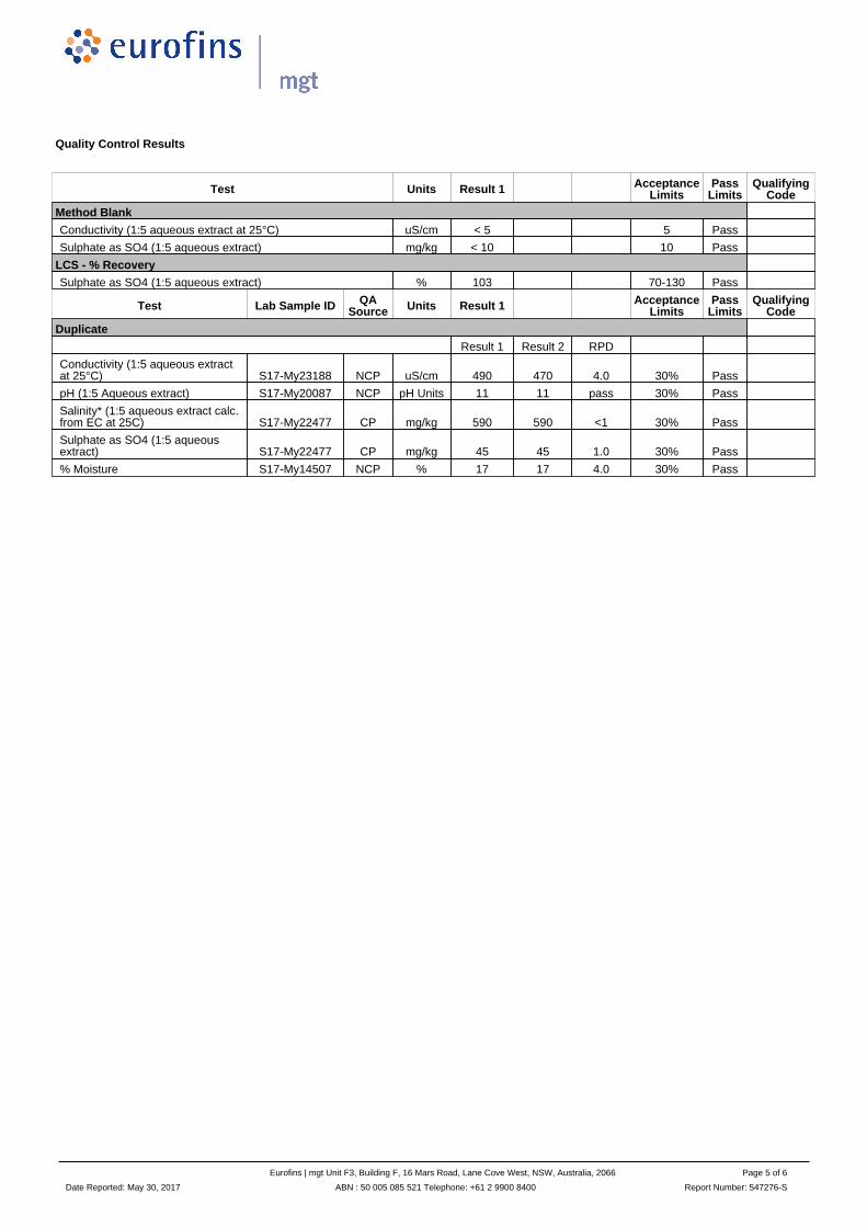
Quality Control Results
Test Units Result 1 AcceptanceLimits
PassLimits
QualifyingCode
Method Blank
Conductivity (1:5 aqueous extract at 25°C) uS/cm < 5 5 Pass
Sulphate as SO4 (1:5 aqueous extract) mg/kg < 10 10 Pass
LCS - % Recovery
Sulphate as SO4 (1:5 aqueous extract) % 103 70-130 Pass
Test Lab Sample ID QASource Units Result 1 Acceptance
LimitsPass
LimitsQualifying
Code
Duplicate
Result 1 Result 2 RPD
Conductivity (1:5 aqueous extractat 25°C) S17-My23188 NCP uS/cm 490 470 4.0 30% Pass
pH (1:5 Aqueous extract) S17-My20087 NCP pH Units 11 11 pass 30% Pass
Salinity* (1:5 aqueous extract calc.from EC at 25C) S17-My22477 CP mg/kg 590 590 <1 30% Pass
Sulphate as SO4 (1:5 aqueousextract) S17-My22477 CP mg/kg 45 45 1.0 30% Pass
% Moisture S17-My14507 NCP % 17 17 4.0 30% Pass
Date Reported: May 30, 2017
Eurofins | mgt Unit F3, Building F, 16 Mars Road, Lane Cove West, NSW, Australia, 2066
ABN : 50 005 085 521 Telephone: +61 2 9900 8400
Page 5 of 6
Report Number: 547276-S

Comments
Sample IntegrityCustody Seals Intact (if used) N/A
Attempt to Chill was evident Yes
Sample correctly preserved Yes
Appropriate sample containers have been used Yes
Sample containers for volatile analysis received with minimal headspace Yes
Samples received within HoldingTime Yes
Some samples have been subcontracted No
Authorised By
Mary Makarios Analytical Services Manager
Ryan Hamilton Senior Analyst-Inorganic (NSW)
Ryan Hamilton Senior Analyst-Metal (NSW)
Glenn Jackson
National Operations Manager
- Indicates Not Requested
* Indicates NATA accreditation does not cover the performance of this service
Measurement uncertainty of test data is available on request or please click here.Eurofins | mgt shall not be liable for loss, cost, damages or expenses incurred by the client, or any other person or company, resulting from the use of any information or interpretation given in this report. In no case shall Eurofins | mgt be liable for consequential damages including, but notlimited to, lost profits, damages for failure to meet deadlines and lost production arising from this report. This document shall not be reproduced except in full and relates only to the items tested. Unless indicated otherwise, the tests were performed on the samples as received.
Date Reported: May 30, 2017
Eurofins | mgt Unit F3, Building F, 16 Mars Road, Lane Cove West, NSW, Australia, 2066
ABN : 50 005 085 521 Telephone: +61 2 9900 8400
Page 6 of 6
Report Number: 547276-S