geosynthetics in barrier s for hydrocarbon remediation in ...geoeng.ca/directory/kerry pub/2014...
TRANSCRIPT
1 INTRODUCTION
Two fuel spills from fuel storage tanks at Australia’s Casey station (66°17' S 110°31' E) in Antarctica, identified in 1999 and 2012, resulted in elevated hydrocarbon levels detected in soil surrounding both sources. The clean-up required cost-effective remediation techniques suitable for the Antarctic conditions that would meet obligations under the Protocol on Environmental Protection of the Antarctic Treaty.
Remediation of the 1999 fuel spill was the first major instance in Antarctica of a comprehensive on- site remediation strategy which involved managing the contaminated site using a combination of ap-proaches and technologies: permeable reactive barriers (PRBs) and biopiles. Both technologies use geo-synthetics in their barrier design and while geosynthetics are commonly used with confidence in less ex-treme environments, there is a degree of uncertainty about their short and long-term performance in Antarctica. Research and investigations conducted so far have assisted to provide an evidence base for the efficacy of these products as barriers to contaminant migration in the short-term. Ongoing and future re-search is required to understand the long-term efficacy and to guide future management of remediation sites including the success of future geosynthetic barrier systems for many uses: landfills, biopiles.
This is particularly important for contaminated sites in Antarctica, where insufficiently managed re-mediation activities can lead to high impact environmental damage. In addition, the increased costs and logistical constraints of working in remote locations require technologies with minimal maintenance and management. Research into long-term performance of geosynthetics enables management plans to be prepared with a focus on eliminating unnecessary activity. As long as humans remain active in Antarctica, future contaminated sites are inevitable and investigation and monitoring of the performance of geosyn-thetics creates the opportunity for well-managed use in both new and legacy sites.
In 2013, the Committee for Environmental Protection of the Antarctic Treaty agreed that remediation of contaminated sites in Antarctica would receive the highest priority attention. The work at Australia’s Casey station is contributing to the development of an international Contaminated Sites Clean-up Manual and will inform future remediation management approaches across the continent.
Geosynthetics in barriers for hydrocarbon remediation in Antarctica
R.S. McWatters, D. Wilkins, T. Spedding, G. Hince & I. Snape Australian Antarctic Division, Kingston, Australia
R.K. Rowe & D. Jones GeoEngineering Center at Queen’s-RMC, Queen’s University, Kingston, Canada
A. Bouazza & W.P. Gates Monash University, Melbourne, Australia
ABSTRACT: An overview of geosynthetics used in contained treatment cells (biopiles) for remediation of two fuel spills at Casey station, Antarctica, is presented. The challenges associated with design and ap-plication in an Antarctic environment and areas of research are highlighted. This is the first instance of geosynthetics being used in Antarctica for remediation and research activities. Seven biopiles were con-structed and the barrier system used different combinations of geosynthetic clay liners (GCLs), high den-sity polyethylene (HDPE) geomembranes and geotextiles to investigate the best composite liner to man-age hydrocarbon migration in the cold, dry and extreme climate. One biopile uses a co-extruded HDPE with ethylene vinyl alcohol (EVOH) geomembrane; the first field site for this novel membrane. A geo-membrane exposure test investigates the long-term performance with exposure to UV, solar radiation and atmosphere. Geosynthetics were also used in the vertical barrier system of permeable reactive barriers (PRBs) and separation barriers between contaminated and uncontaminated soils. Four generations of geo-textile covers were used and discussed. Results from this project will provide the international Antarctic community with better informed options for managing and remediating contaminated sites originating from human impacts, whether legacy sites or modern sites.
Keywords: Biopiles, cold regions engineering, geomembranes, GCL, hydrocarbon-contaminated soil.

Figure 1. Summer view of 1999 fuel spill area including fuel tank (source), upper and lower PRBs, biopiles and geosynthetic
test plot. Extent of the contaminated and excavated area is not shown.
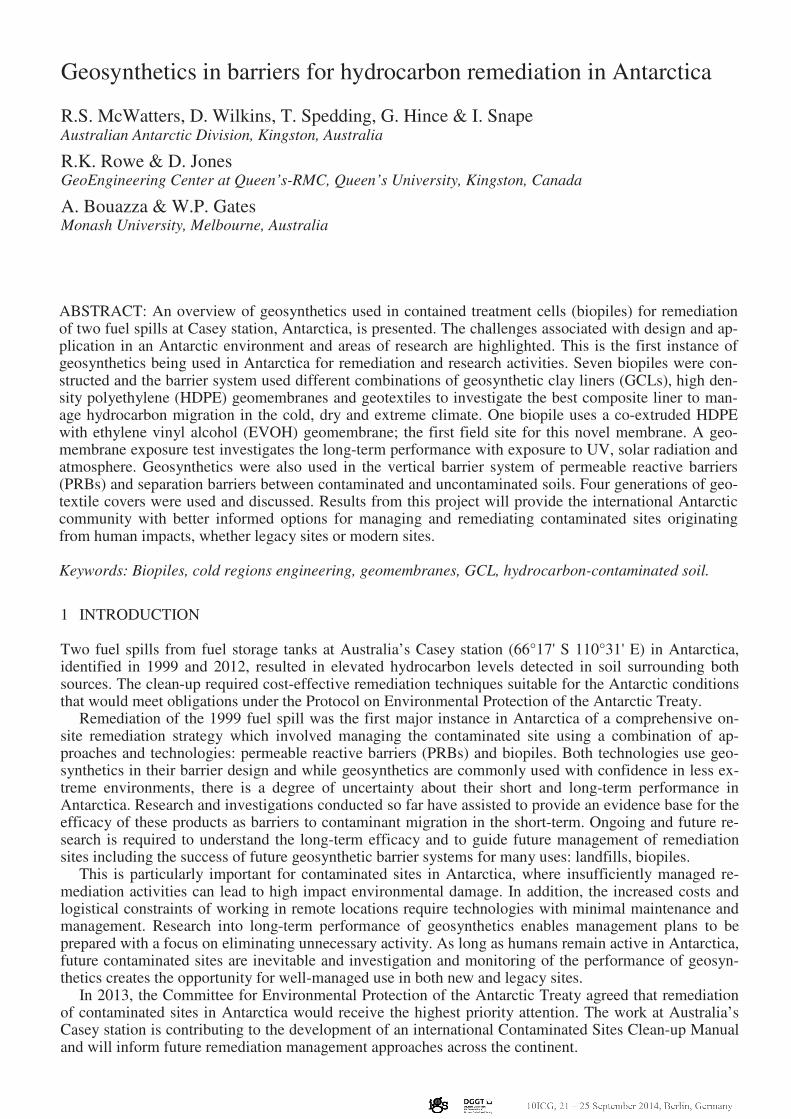
The first stage of the remediation approach adopted at Casey station was installation of the funnel-and-gate PRB down-gradient of the 1999 fuel spill in 2005. This PRB underwent replacement of the reactive material in 2010 prior to excavation of the up-gradient soil in 2011 through 2012 (Mumford et al. 2013). Mumford et al. (2014) studied the performance of the PRB during the first five years for fuel reten-tion/degradation characteristics and hydraulic performance in the Antarctic environment. Additional tem-porary and long-term PRBs were installed in 2011, 2013 and 2014 at the contaminated sites as the first step in managing the risks of contaminant migration throughout the remediation process and especially prior to excavation. Two of the PRBs (Upper and Lower) on the 1999 fuel spill site are shown in Figure 1. Geosynthetics were used in the funnel to direct groundwater to the barrier treatment cages. The next phase of the remediation process was to construct geosynthetic lined containment cells (bio-piles) in which hydrocarbon-contaminated soil was treated. Biopiles are an active soil treatment method, with nutrient addition and aeration systems specifically tailored to the site and soil conditions. The biopile design also included addressing the risks associated with remote Antarctic operations and the cold, dry environment. Contaminated soil was excavated from both fuel spill sites during the summers of 2011 through 2013 and placed in seven biopile treatment cells. Six biopile treatment cells were designed with a geosynthetic composite liner system using geosynthetic clay liners (GCL), high density polyethylene (HDPE) geomembranes (GMB) and geotextiles (GTX). The seventh biopile was created using a co-extruded HDPE/EVOH/HDPE geomembrane with an inner ethyl vinyl alcohol (EVOH) barrier. Geotextiles were used as the cover system to prevent off-site dust migration. The seven biopiles are shown in Figure 1 (numbered in chronological order as they were con-structed). This is the first time geosynthetics have been used and studied in field applications in Antarc-tica. It is also the first instance of a field trial with the co-extruded HDPE/EVOH/HDPE geomembrane. In 2012, ice removal identified a new area of hydrocarbon-contaminated soil, with the source of the spill traced to a weeping joint in a fuel line. Remediation began in late 2012 with partial excavation of contaminated soil and installation of a temporary PRB using geotubes (woven geotextile 2 x 4 x 0.5m) to contain the barrier treament material of granulared activated carbon (GAC), but allow contaminated groundwater and meltwater to flow through the geotube and exit as treated water. Figure 2 (far left) shows geotubes installed vertically in the ground and (middle left) the GAC placed inside the geotube. These PRBs were necessary to prevent off-site migration of hydrocarbons during remediation activities. In addition, temporary vertical GMB and GCL separation barriers between contaminated and
uncontaminated soil were installed (Figure 2 middle right). Excavated contaminated soil from site was placed into this seventh biopile constructed in 2013. A long-term PRB replaced the temporary PRB in 2014 and incorporated GCL and HDPE/EVOH/HDPE in the funnel and is shown in Figure 2 (far right). Research is focused on the effectiveness of the biopile technique at remediating soil as well as the long-term performance of the geosynthetics used in the barrier system to impede advective and diffusive contaminant migration under Antarctic climatic conditions: cold, arid and freeze-thaw cycling.
There are very few scientific studies that have investigated geosynthetics used in extreme climates (Bathurst et al., 2006), and there are no previous studies specific to Antarctic environment. Therefore, the aim of this research is to provide scientifically informed options for barrier systems for management of contaminated sites within the Australian Antarctic Territory and other regions of Antarctica. This paper provides an overview of all the geosynthetics employed in the barrier systems being researched at Casey station, Antarctica: biopiles, temporary containment barriers, and permeable reactive barriers. It also showcases the long-term performance and exposure testing sites for GCL and geomembranes: biopiles, test plot, and geomembrane exposure test.
2 GEOSYNTHETICS IN BIOPILES
2.1 Overview
Contaminated soil was excavated from the two fuel spill sites. From the 1999 site, approximately 600m3
was removed from a 780m2 area. From the 2011 site, approximately 135m
3 was removed from a 180m
2
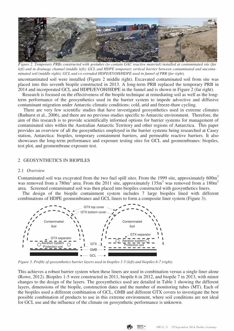
area. Screened contaminated soil was then placed into biopiles constructed with geosynthetics liners. The design of the biopile containment system includes 7 large biopiles lined with different combinations of HDPE geomembranes and GCL liners to form a composite liner system (Figure 3).
This achieves a robust barrier system when these liners are used in combination versus a single liner alone (Rowe, 2012). Biopiles 1-5 were constructed in 2011, biopile 6 in 2012, and biopile 7 in 2013, with minor changes to the design of the layers. The geosynthetics used are detailed in Table 1 showing the different layers, dimensions of the biopile, construction dates and the number of monitoring tubes (MT). Each of the biopiles used a different combination of GCL, GMB and different GTX covers to investigate the best possible combination of products to use in this extreme environment, where soil conditions are not ideal for GCL use and the influence of the climate on geosynthetic performance is unknown.
Aeration system
Protection soil
Contaminated
Soil
GTX top cover
GTX bottom cover
GTX separator
GMB
GCL
Contaminated
Soil
Aeration system Protection soil
GTX separator
GTX
Figure 3. Profile of geosynthetics barrier layers used in biopiles 1-5 (left) and biopiles 6-7 (right).
Figure 2. Temporary PRBs constructed with geotubes (to contain GAC reactive material) installed at contaminated site (far
left) and in drainage channel (middle left); GCL and HDPE temporary vertical barrier between contaminated and unconta-
minated soil (middle right); GCL and co-extruded HDPE/EVOH/HDPE used in funnel of PRB (far right).
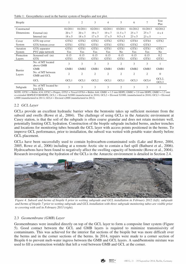
Table 1: Geosynthetics used in the barrier system of biopiles and test plot.
Biopile 1 2 3 4 5 6 7 Test
Plot
Constructed 01/2011 01/2011 02/2011 02/2011 03/2011 01/2012 01/2013 02/2012
Dimensions External (m)
Internal (m)
20 x 7
18 x 5
20 x 7
18 x 5
19 x 7
17 x 5
19 x 7
17 x 5
11.5 x 7
9.5 x 5
25 x 7
23 x 5
25 x 7 4 x 4
- 23 x 5
Cover
System
GTX top cover GTX2 GTX2 GTX2 GTX2 GTX2 GTX4 GTX4 GTX2
GTX bottom cover GTX1 GTX1 GTX1 GTX1 GTX1 GTX2 GTX3 -
Aeration
System
GTX separator GTX1 GTX1 GTX1 GTX1 GTX1 GTX1 GTX1 GTX1
PVC pipe network Yes Yes Yes Yes No Yes Yes No
Protection
Layers
Screened soil (m) 0.15 0.15 0.15 0.15 0.15 0.15 0.15 0.2
GTX GTX1 GTX1 GTX1 GTX1 GTX1 GTX1 GTX1 GTX1
Barrier
Layers
No. of MT located
above GMB 3 3 3 3 2 3 3 1
GMB GMB1 GMB2 GMB1 GMB1 GMB1 GMB2 GMB3 GMB1
No. of MT between
GMB and GCL 2 2 2 2 2 2 2 0
GCL GCL1 GCL1 GCL2 GCL1 GCL1 GCL3 GCL4 GCL2,
GCL3
Subgrade No. of MT located be-
low GCL 3 3 3 3 2 3 3 1
NOTE: GTX1 = Bidim A34; GTX2 = Propex, GTX3 = Texcel GTX4 = Bidim A44; GMB1 = 1.5 mm HDPE; GMB2 = 2.0 mm HDPE; GMB3 = 1.5 mm
co-extruded HDPE/EVOH/HDPE; GCL1 = Elcoseal X2000 (manufactured in 2010); GCL2 = Elcoseal X1000, (manufactured in 2010); GCL3 = Elcoseal
x2000 (manufactured in 2011); GCL4 = Elcoseal x2000 (manufactured in 2012).
2.2 GCL Layer
GCLs provide an excellent hydraulic barrier when the bentonite takes up sufficient moisture from the subsoil and swells (Rowe et al., 2004). The challenge of using GCLs in the Antarctic environment at Casey station, is that the soil of the subgrade is often coarse granular and does not retain moisture well, potentially limiting GCL hydration. Construction of the biopile subgrade included berms, anchor trenches and locations for monitoring tubes beneath the GCL layer with access points positioned in the berms. To improve GCL performance, prior to installation, the subsoil was wetted with potable water shortly before GCL placement.
GCLs have been successfully used to contain hydrocarbon-contaminated soils (Lake and Rowe, 2004, 2005, Rowe et al., 2006) including at a remote Arctic site to contain a fuel spill (Bathurst et al., 2006). Hydrocarbons have been found to negatively affect the swelling capacity of bentonite (Rowe et al., 2004). Research investigating the hydration of the GCLs in the Antarctic environment is detailed in Section 2.4.
2.3 Geomembrane (GMB) Layer
Geomembranes were installed directly on top of the GCL layer to form a composite liner system (Figure 5). Good contact between the GCL and GMB layers is required to minimize transmissivity of contaminants. This was achieved for the interior flat sections of the biopile but was more difficult over the berms and in the corner sections of the berms. In 2014, repairs were made to a corner section of Biopile 6 to prevent melt-water ingress between the GMB and GCL layers. A sand/bentonite mixture was used to fill a construction wrinkle that left a void between GMB and GCL at the corner.
Figure 4. Subsoil and berms of biopile 6 prior to wetting subgrade and GCL installation in February 2012 (left); subgrade
and berms of biopile 7 prior to wetting subgrade and GCL installation with three subgrade monitoring tubes are visible prior
to covering with soil in February 2013 (right).
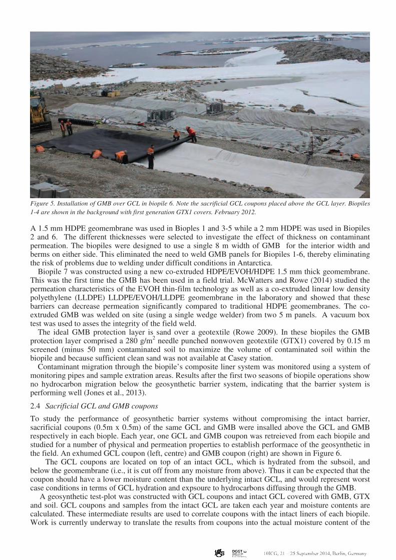
Figure 5. Installation of GMB over GCL in biopile 6. Note the sacrificial GCL coupons placed above the GCL layer. Biopiles
1-4 are shown in the background with first generation GTX1 covers. February 2012.
A 1.5 mm HDPE geomembrane was used in Bioples 1 and 3-5 while a 2 mm HDPE was used in Biopiles 2 and 6. The different thicknesses were selected to investigate the effect of thickness on contaminant permeation. The biopiles were designed to use a single 8 m width of GMB for the interior width and berms on either side. This eliminated the need to weld GMB panels for Biopiles 1-6, thereby eliminating the risk of problems due to welding under difficult conditions in Antarctica. Biopile 7 was constructed using a new co-extruded HDPE/EVOH/HDPE 1.5 mm thick geomembrane. This was the first time the GMB has been used in a field trial. McWatters and Rowe (2014) studied the permeation characteristics of the EVOH thin-film technology as well as a co-extruded linear low density polyethylene (LLDPE) LLDPE/EVOH/LLDPE geomembrane in the laboratory and showed that these barriers can decrease permeation significantly compared to traditional HDPE geomembranes. The co-extruded GMB was welded on site (using a single wedge welder) from two 5 m panels. A vacuum box test was used to asses the integrity of the field weld. The ideal GMB protection layer is sand over a geotextile (Rowe 2009). In these biopiles the GMB protection layer comprised a 280 g/m
2 needle punched nonwoven geotextile (GTX1) covered by 0.15 m
screened (minus 50 mm) contaminated soil to maximize the volume of contaminated soil within the biopile and because sufficient clean sand was not available at Casey station.
Contaminant migration through the biopile’s composite liner system was monitored using a system of monitoring pipes and sample extration areas. Results after the first two seasons of biopile operations show no hydrocarbon migration below the geosynthetic barrier system, indicating that the barrier system is performing well (Jones et al., 2013).
2.4 Sacrificial GCL and GMB coupons
To study the performance of geosynthetic barrier systems without compromising the intact barrier, sacrificial coupons (0.5m x 0.5m) of the same GCL and GMB were insalled above the GCL and GMB respectively in each biople. Each year, one GCL and GMB coupon was retreieved from each biopile and studied for a number of physical and permeation properties to establish performace of the geosynthetic in the field. An exhumed GCL coupon (left, centre) and GMB coupon (right) are shown in Figure 6.
The GCL coupons are located on top of an intact GCL, which is hydrated from the subsoil, and below the geomembrane (i.e., it is cut off from any moisture from above). Thus it can be expected that the coupon should have a lower moisture content than the underlying intact GCL, and would represent worst case conditions in terms of GCL hydration and expsoure to hydrocarbons diffusing through the GMB.
A geosynthetic test-plot was constructed with GCL coupons and intact GCL covered with GMB, GTX and soil. GCL coupons and samples from the intact GCL are taken each year and moisture contents are calculated. These intermediate results are used to correlate coupons with the intact liners of each biopile. Work is currently underway to translate the results from coupons into the actual moisture content of the
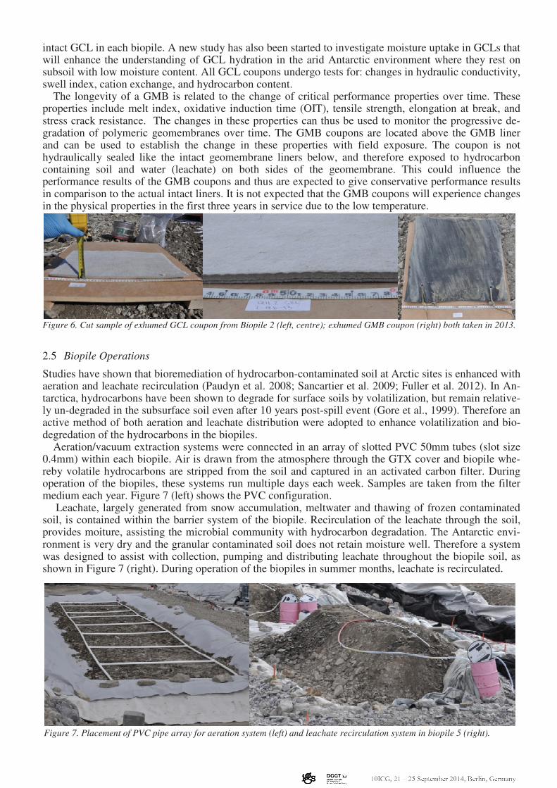
intact GCL in each biopile. A new study has also been started to investigate moisture uptake in GCLs that will enhance the understanding of GCL hydration in the arid Antarctic environment where they rest on subsoil with low moisture content. All GCL coupons undergo tests for: changes in hydraulic conductivity, swell index, cation exchange, and hydrocarbon content. The longevity of a GMB is related to the change of critical performance properties over time. These properties include melt index, oxidative induction time (OIT), tensile strength, elongation at break, and stress crack resistance. The changes in these properties can thus be used to monitor the progressive de-gradation of polymeric geomembranes over time. The GMB coupons are located above the GMB liner and can be used to establish the change in these properties with field exposure. The coupon is not hydraulically sealed like the intact geomembrane liners below, and therefore exposed to hydrocarbon containing soil and water (leachate) on both sides of the geomembrane. This could influence the performance results of the GMB coupons and thus are expected to give conservative performance results in comparison to the actual intact liners. It is not expected that the GMB coupons will experience changes in the physical properties in the first three years in service due to the low temperature.
Figure 6. Cut sample of exhumed GCL coupon from Biopile 2 (left, centre); exhumed GMB coupon (right) both taken in 2013.
2.5 Biopile Operations
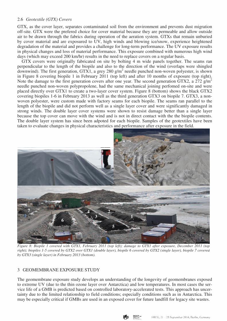
Studies have shown that bioremediation of hydrocarbon-contaminated soil at Arctic sites is enhanced with aeration and leachate recirculation (Paudyn et al. 2008; Sancartier et al. 2009; Fuller et al. 2012). In An-tarctica, hydrocarbons have been shown to degrade for surface soils by volatilization, but remain relative-ly un-degraded in the subsurface soil even after 10 years post-spill event (Gore et al., 1999). Therefore an active method of both aeration and leachate distribution were adopted to enhance volatilization and bio-degredation of the hydrocarbons in the biopiles. Aeration/vacuum extraction systems were connected in an array of slotted PVC 50mm tubes (slot size 0.4mm) within each biopile. Air is drawn from the atmosphere through the GTX cover and biopile whe-reby volatile hydrocarbons are stripped from the soil and captured in an activated carbon filter. During operation of the biopiles, these systems run multiple days each week. Samples are taken from the filter medium each year. Figure 7 (left) shows the PVC configuration.
Leachate, largely generated from snow accumulation, meltwater and thawing of frozen contaminated soil, is contained within the barrier system of the biopile. Recirculation of the leachate through the soil, provides moiture, assisting the microbial community with hydrocarbon degradation. The Antarctic envi-ronment is very dry and the granular contaminated soil does not retain moisture well. Therefore a system was designed to assist with collection, pumping and distributing leachate throughout the biopile soil, as shown in Figure 7 (right). During operation of the biopiles in summer months, leachate is recirculated.
Figure 7. Placement of PVC pipe array for aeration system (left) and leachate recirculation system in biopile 5 (right).
2.6 Geotextile (GTX) Covers
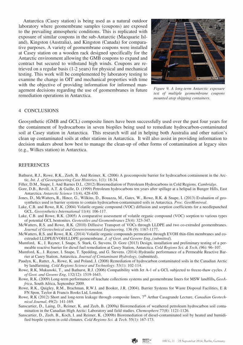
GTX, as the cover layer, separates contaminated soil from the environment and prevents dust migration off-site. GTX were the prefered choice for cover material because they are permeable and allow outside air to be drawn through the fabrics during operation of the aeration system. GTXs that remain unburied by cover material and are exposured to UV, high winds and blowing ice/snow, experience heightened degradation of the material and provides a challenge for long-term performance. The UV exposure results in physical changes and loss of material performance. This exposure combined with numerous high wind days (which may exceed 200 km/hr) results in the need to replace covers on a regular basis. GTX covers were originally fabricated on site by bolting 4 m wide panels together. The seams ran perpendicular to the length of the biopile and also to the direction of the wind (overlaps were shingled downwind). The first generation, GTX1, a grey 280 g/m
2 needle punched non-woven polyester, is shown
in Figure 8 covering biopile 1 in February 2011 (top left) and after 10 months of exposure (top right). Note the damage to the first generation covers after one year. The second generation GTX2, a 272 g/m
2
needle punched non-woven polypropolene, had the same mechanical joining perfomed on-site and were placed directly over GTX1 to create a two-layer cover system. Figure 8 (bottom) shows the black GTX2 covering biopiles 1-6 in February 2013 as well as the third generation GTX3 on biopile 7. GTX3, a non-woven polyester, were custom made with factory seams for each biopile. The seams ran parallel to the length of the biopile and did not perform well as a single layer cover and were significantly damaged in strong winds. The double layer cover systems were shown to resist damage better than a single layer because the top cover can move with the wind and is not in direct contact with the the biopile contents. The double layer system has since been adpoted for each biopile. Samples of the geotextiles have been taken to evaluate changes in physical characteristics and performance after exposure in the field.
3 GEOMEMBRANE EXPOSURE STUDY
The geomembrane exposure study develops an understanding of the longevity of geomembranes exposed to extreme UV (due to the thin ozone layer over Antarctica) and low temperatures. In most cases the ser-vice life of a GMB is predicted based on controlled laboratory-accelerated tests. This approach has uncer-tainty due to the limited relationship to field conditions; especially conditions such as in Antarctica. This may be especially critical if GMBs are used in an exposed cover for future landfill for legacy site wastes.
7
6
4 2
3 1
5
Figure 8: Biopile 1 covered with GTX1, February 2011 (top left); damage to GTX1 after exposure, December 2011 (top
right); biopiles 1-5 covered by GTX2 over GTX1 (double layer), biopile 6 covered by GTX2 (single layer), biopile 7 covered
by GTX3 (single layer) in February 2013 (bottom).
Antarctica (Casey station) is being used as a natural outdoor laboratory where geomembrane samples (coupons) are exposed to the prevailing atmospheric conditions. This is replicated with exposure of similar coupons in the sub-Antarctic (Macquarie Isl-and), Kingston (Australia), and Kingston (Canada) for compara-tive purposes. A variety of geomembrane coupons were installed at Casey station on a wooden rack designed specifically for the Antarctic environment allowing the GMB coupons to expand and contract but secured to withstand high winds. Coupons are re-trieved on a regular basis (1-2 years) for physical and mechanical testing. This work will be complemented by laboratory testing to examine the change in OIT and mechanical properties with time with the objective of providing information for informed man-agement decisions regarding the use of geomembranes in future remediation operations in Antarctica.
4 CONCLUSIONS
Geosynthetic (GMB and GCL) composite liners have been successfully used over the past four years for
the containment of hydrocarbons in seven biopiles being used to remediate hydrocarbon-contaminated
soil at Casey station in Antarctica. This research will aid in helping both Australia and other nation’s
clean up contaminated soils at other stations in Antarctica. It will also assist in providing information to
decision makers about how best to manage the clean-up of other forms of contamination at legacy sites
(e.g., Wilkes station) in Antarctica.
REFERENCES
Bathurst, R.J., Rowe, R.K., Zeeb, B. And Reimer, K. (2006) A geocomposite barrier for hydrocarbon containment in the Arc-tic, Int. J. of Geoengineering Case Histories, 1(1): 18-34.
Filler, D.M., Snape, I. And Barnes D.L. (2012) Bioremediation of Petroleum Hydrocarbons in Cold Regions. Cambridge. Gore, D.B., Revill, A.T. & Guille, D. (1999) Petroleum hydrocarbons ten years after spillage at a helipad in Bunger Hills, East
Antarctica. Antarctic Science 11(4), 428-430. Jones, D., McWatters, R., Hince, G., Wilkins, D., Bouazza, M., Gates, W., Rowe, R.K. & Snape, I. (2013) Evaluation of geo-
synthetics used in barrier systems to contain hydrocarbon-contaminated soils in Antarctica. Proc. GeoMontreal. Lake, C.B. and Rowe, R.K. (2004) Volatile organic compound (VOC) diffusion and sorption coefficients for a needlepunched
GCL. Geosynthetics International 11(4): 106-117. Lake, C.B. and Rowe, R.K. (2005) A comparative assessment of volatile organic compound (VOC) sorption to various types
of potential GCL bentonites. Geotextiles and Geomembranes 23(4): 323-347. McWatters, R.S. and Rowe, R.K. (2010) Diffusive Transport of VOCs through LLDPE and two co-extruded geomembranes.
Journal of Geotechnical and Geoenvironmental Engineering, 136 (9): 1167-1177. McWatters, R.S. and Rowe, R.K. (2014) Volatile organic compounds permeation through EVOH thin-film membranes and co-
extruded LLDPE/EVOH/LLDPE geomembrane. J. of Geot. and Geoenv Eng.,(submitted). Mumford, K., J. Rayner, I. Snape, S. Stark, G. Stevens, D. Gore (2013) Design, installation and preliminary testing of a per-
meable reactive barrier for diesel fuel remediation at Casey Station, Antarctica. Cold Regions Sci. & Tech, (96): 96–107. Mumford, K., J. Rayner, I. Snape, T. Spedding, and G. Stevens. (2014) Hydraulic performance of a Permeable Reactive Bar-
rier at Casey Station, Antarctica. Journal of Contaminant Hydrology, (submitted). Paudyn, K., Rutter, A., Rowe, K. and Poland, J. (2008) Remediation of hydrocarbon contaminated soils in the Canadian Arctic
by landfarming. Cold Regions Science and Technology. 53(1): 102-114. Rowe, R.K, Mukunoki, T., and Bathurst, R.J. (2006) Compatibility with Jet A-1 of a GCL subjected to freeze-thaw cycles. J.
of Geot. and Geoenv Eng, 132(12): 1519-1643. Rowe, R.K. (2009) Long-term performance of leachate collections systems and geomembrane liners for MSW landfills, GeoA-
frica, South Africa, September 2009. Rowe, R.K., Quigley, R.M., Brachman, R.W.I. and Booker, J.R. (2004). Barrier Systems for Waste Disposal Facilities, E &
FN Spon, Taylor & Francis Books Ltd, London. Rowe, R.K (2012) Short and long-term leakage through composite liners, 7
th Arthur Casagrande Lecture, Canadian Geotech-
nical Journal, 49(2): 141-169. Sanscartier, D., Laing, D., Reimer, K. and Zeeb, B. (2009a) Bioremediation of weathered petroleum hydrocarbon soil conta-
mination in the Canadian High Arctic: Laboratory and field studies. Chemosphere.77(8): 1121-1126. Sanscartier, D., Zeeb, B., Koch, I. and Reimer, K. (2009b) Bioremediation of diesel-contaminated soil by heated and humidi-
fied biopile system in cold climates. Cold Regions Sci. & Tech. 55(1): 167-173.
Figure 9. A long-term Antarctic exposure
test of multiple geomembrane coupons
mounted atop shipping containers.