george mason university sub i - pennsylvania state … 1.pdf · george mason university sub i ‐...
TRANSCRIPT

ARCHITECTURAL ENGINEERING SENIOR THESIS
George Mason University Student Union Building I
Fairfax, VA
Technical Assignment I
Brett Robinson Construction Management AE Faculty Consultant: Chris Magent
10/5/2009

George Mason University SUB I ‐ Fairfax, VA Brett Robinson AE Faculty Consultant: Chris Magent Construction Management
Technical Assignment I October 5, 2009 Page | 2
Table of Contents
A. Executive Summary………………………………………………………………………….…3 B. Project Summary Schedule……………………………………………………………….…4
C. Building Systems Summary…………………………………………………………………6
D. Project Cost Evaluation………………………………………………………………………11 E. Site Plan of Existing Conditions…………………………………………………………..13 F. Local Conditions………………………………………………………………………………...14 . .
G Client Information……………………………………………………………………………...16
H Project Delivery System……………………………………………………………………..17 I. Staffing Plan………………………………………………………………………………………19
…………………………………..21 J. Appendix………………………………………………………

George Mason University SUB I ‐ Fairfax, VA Brett Robinson AE Faculty Consultant: Chris Magent Construction Management
Technical Assignment I October 5, 2009 Page | 3
Executive Summary The Technical Assignment 1 provides an introduction to the George Mason University Student Union Building I. This assignment takes an in‐depth look at the existing conditions and specific construction management techniques that were used on the project. This report ns: includes the following sectio
• Project Schedule Summaystems Summ
• ation
ry • ary Building S
• Project Cost Evalu
•
Site PlanLocal Conditions
ation • ry System • Client Inform
Project Delive• Staffing Plan
The GMU SUB I project is a $17 million addition to the existing Student Union Building. The four story addition is located on the Fairfax, Virginia Campus. George Mason University selected Hess Construction + Engineering Services as the Design‐Builder. Hess Construction + Engineering Services has an extensive background in constructing educational facilities. Hess has consequently staffed the project accordingly with a staff that has a vast knowledge of educational facilities and tight construction sites. This project is very distinctive in the sense that the construction site is very small. This concept will be further detailed in the Site Plan Section.

George Mason University SUB I ‐ Fairfax, VA Brett Robinson AE Faculty Consultant: Chris Magent Construction Management
Technical Assignment I October 5, 2009 Page | 4
Project Schedule Summa
ry
Please See Project Schedule Summary in Appendix Page # 1 The schedule is broken down into three phases. These phases consist of the BCOM Building pproval, Site Plan/Foundation/Superstructures Approval and the Construction of Student nion Building I.
AU Key Elements of the PreConstruction Sequence The pre‐construction phase in this project is very important. The Bureau of Capital Outlay Management (BCOM) Submission and Approval process is a lengthy, tedious process. To become more familiar with the BCOM process, the project management team from Hess Construction + Engineering Services went through a BCOM certified course. Due to the fact that the project is design‐build the pre‐construction phase is very coordination heavy in the early stages of the project. There are regular meetings with BCOM and the design team to allow the project to move as quickly and efficiently as possible.
Key Elements of the Construction Sequence Site Excavation & Foundation Sequence This sequence is currently taking place on site at George Mason University. During the process, the first order of work was the removal of trees on the North and South Side of the project. This process laid the way for a new ADA sidewalk that connects from the Mason Pond Parking Deck across Aquia Creek Lane connecting to the Union Building. After these areas were complete, the demolition of the parking lot was slated. The asphalt parking ot spanned the entire area of the Student lUnion Building’s Floor plan. Upon completion of the demolition, the foundation work for the Geopier System began. This process involves the drilling of a 30” diameter hole to various depths and arrangements. Subsequently, lifts of 12” aggregate will be placed into the hole and compacted to form a bell shape. Once this process is completed this will furnish a net llowable bearing capacity of 6,000 psi at he bottom surface of the footing element. at
lease See Structural Foundation/First Floor Plan in Appendix Page # 2
Geopier Cutaway
P

George Mason University SUB I ‐ Fairfax, VA Brett Robinson AE Faculty Consultant: Chris Magent Construction Management
Technical Assignment I October 5, 2009 Page | 5
Structural Sequence The str g e ed: uctural phasin for th Student Union Building is as follow
• Phase One – 2nd nd 3rd Floors, Northeast portion of SUd
•
a B I • B I Phase Two ‐ 2n and 3rd Floors, Northwest portion of SU
• Phase Three – 4th and Roof, Northeast portion of SUB I
B I •
Phase Four ‐ 4th and Roof, Northwest portion of SU a F
• Phase Five ‐ 2nd nd 3rd loors, Southeast portion of SUB I
• SUB I Phase Six ‐ 4th and Roof, Southeast portion of SUB I Phase Seven ‐ 2nd and 3rd Floors, Southwest portion of
• Phase Eight ‐ 4th and Roof, Southwest portion of SUB I
The steel will be erected strictly from the North side of each phase to the South side. The reason the steel is sequenced in this manner is due to the fact that the George Mason site is so tight. The erection of a new Data Center to the North of the project adds further compaction to an already tight site and restricted the steel from being erected from South to North.
lease See Steel Erection Phasing Plan in Appendix Page # 3 P Finish Sequence Interior finishes will be one the longest items in the construction schedule sequence, consisting of 80 days. It will begin on January 28, 2009, immediately after the exterior skin is finished. This sequence will run simultaneously with the MEP Main Distribution and Equipment installation. To ease the construction process between Architectural, Structural and MEP item, Building Information Modeling will be used for coordination purposes. BIM has been involved throughout the entire design of the Student Union Project. Although hree dimensional modeling is being used, two dimensional drawings take precedence in tany dispute. As stated before, major overhead MEP work will run simultaneously as the interior work. As of now the eted in this manner: interior work will be compl
• In Metal Studs Wall Rough‐
• • MEP In Wall Rough‐In
allation • d Installation
Door Frame Inst
• Gypsum Wall Boar
• Paint First Coat
ork • o Grid
Ceiling Grid Ws t
• MEP Drop
• Finish Paint Flooring
• Installation Acoustical Ceiling Tile• Doors and Hardware

George Mason University SUB I ‐ Fairfax, VA Brett Robinson AE Faculty Consultant: Chris Magent Construction Management
Technical Assignment I October 5, 2009 Page | 6
Building Systems Summary
Yes/No Work Scope Yes Demolition Yes Structural Steel Frame Yes Cast In Place Concrete No Precast Concrete Yes Mechanical System Yes Electrical System Yes Masonry Yes Curtain Wall Yes Support of Excavation
Demolition Selective demolition was required for several portions of the project. The site‐work contractor C.W Strittmatter Inc. was responsible for the demolition of the following activities:
• nnel (HTW) Existing High Temperaan
• k
ture Water Tu• d Walkways Existing Parking Lot
• Existing Loading Doc
ouses •
Existing Gateh
• Existing Light Poles Tree Removal
• Existing Student Union Building I
High Temperature Water Tunnel (HTW) – George Mason University confirmed there was no asbestos inside the exiting HTW Tunnel. The existing HTW pipes were then capped. The emoval of (2) 136’ of 3” HTW pipe and the demolition of 136’ of concrete that made up the 0’ x 3’‐ 9” HTW Tunnel followed. r1 Existing Parking Lot and Walkways – The asphalt parking lot and concrete walkways in front of the existing Student Union Building I will be demolished to allow for construction f the Student Union Building I addition. The area that is to be demolished is roughly 1,000 sq. ft. o2 Existing Loading Dock – The entire existing 21’ x 10’ concrete loading dock (South) will be emolished to make allow for (2) 30” geopiers with steel columns and the new 26’ x 7’‐ 9” oncrete slab loadindc g dock. Existing Gatehouses – (2) existing gatehouses located on Aquia Creek Lane will be removed. he metal from the gatehouses will be recycled/reused. The 5” concrete pad that is upports the gatehouses will be demolished. Ts

George Mason University SUB I ‐ Fairfax, VA Brett Robinson AE Faculty Consultan
Page | 7
t: Chris Magent Construction Management
Existing Light Poles – (12) existing light poles will be removed along with their concrete ases and associated conduit/wiring. These light poles will be reused to light new idewalks on site.
Technical Assignment I October 5, 2009
(All Roof Areas are Designed for Minimum 30 psf Live/Snow Load)
The Student Union Building will use wide flange beams and columns that conform to ASTM A992/A992M–06a. The Headed Stud–Type Shear Connectors conform to ASTM A108–07. These are Cold‐Finished, Grade 1015 or 1020 shear connectors. Anchor Bolts conform to ASTM A307–07a, the anchor bolts are rated at 60,000 PSI Tensile Strength and are of the non‐headed type. High–Strength Threaded Fasteners are specified to conform to either ASTM A325–07, Standard Specification for Structural Bolts, Steel, Heat Treated, 120/105 ksi Minimum Tensile Strength, or ASTM A490–06, Standard Specification for Structural Bolts, Alloy Steel, Heat Treated, 150 ksi Minimum Tensile Strength.
bs Tree Removal – George Mason University wanted to save as many trees as possible that did not interfere with the building pad. Their main concern for a specific type of tree was any tree 6” or larger in diameter and NOT a pine tree. GMU wanted to approve any trees that were sought to be removed outside the building pad. Both on the North and South roughly sixty trees were removed, many of these trees were in the building pad. Eight trees were removed from the site and moved to another place on campus. It is planned to replant 16 trees deciduous trees consisting of October Glory Red Maple, Japanese Zeicova, White ringetree, and Yoshino Cherry and 36 shrubs consisting of Blue Princess Holly and ensiformis Yew.
FD Existing Student Union Building I – The entire Western exterior wall on the existing Student Union Building I is to be demolished. This wall is 3 stories of 135 linear feet of wall per floor.
Structural Steel Frame
he structural system used in the George Mason University Student Union Building I is Tstructural steel. The design loa udent Union Building I are as followed: ds for the St
• Live Loads
o + 20 psf (Partitions) o Assembly Areas – 100 psf
Administrative Offices – 8
o
0 psfo Stairs and Corridors – 100 psf
t) – 125 psf quipment Weight)
Storage (Lighanical Rooms – 150 psf (or Heavier per Eo Mech
o • Snow L
Roof – 30 psf oads
o o Ground Snow Load (Pg) – 25 psf
Snow Exposure Factor (Ce) – 1.0 o Snow Importance Factor (I) ‐ 1.2
Flat Roof Snow Load (Pf) – 26 psf + Snow Drift o
George Mason University SUB I ‐ Fairfax, VA Brett Robinson E Faculty Consultant: Chris Magent Construction Management
Technical Assignment I October 5, 2009 Page | 8
A
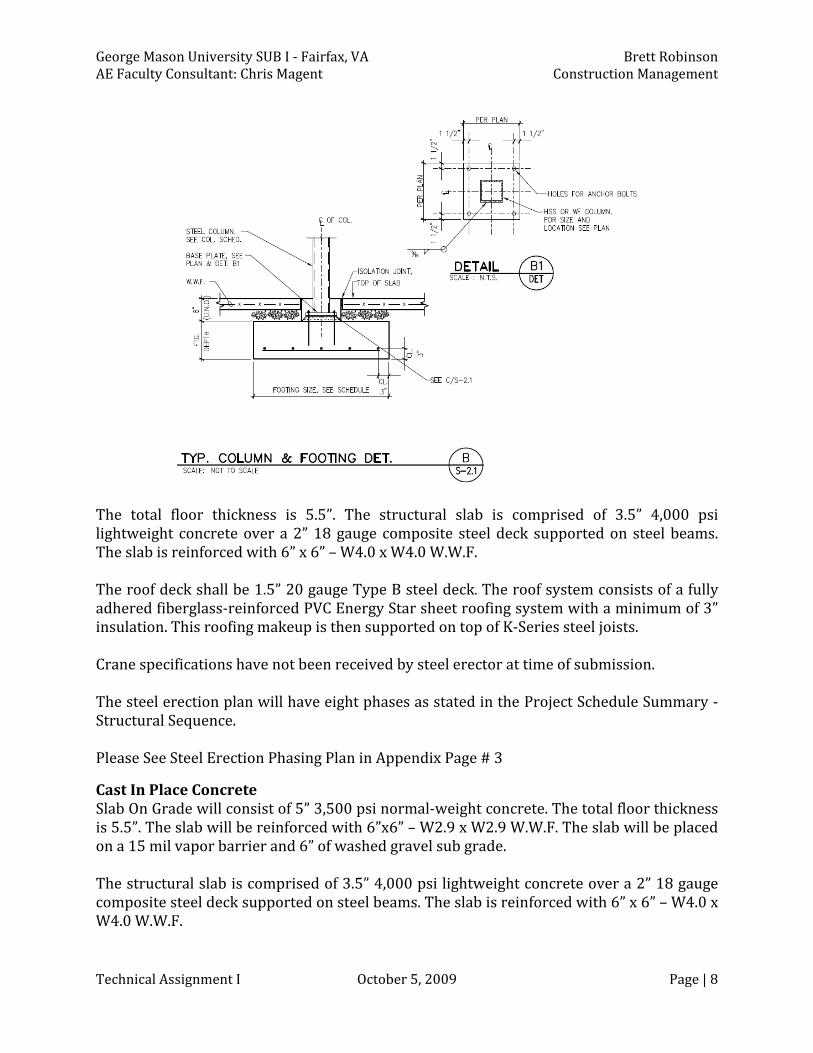
The total floor thickness is 5.5”. The structural slab is comprised of 3.5” 4,000 psi ightweight concrete over a 2” 18 gauge composite steel deck supported on steel beams. lThe slab is reinforced with 6” x 6” – W4.0 x W4.0 W.W.F. The roof deck shall be 1.5” 20 gauge Type B steel deck. The roof system consists of a fully dhered fiberglass‐reinforced PVC Energy Star sheet roofing system with a minimum of 3” ainsulation. This roofing makeup is then supported on top of K‐Series steel joists. Crane specifications have not been received by steel erector at time of submission. he steel erection plan will have eight phases as stated in the Project Schedule Summary ‐ TStructural Sequence. Please See Steel Erection Phasing Plan in Appendix Page # 3
Cast In Place Concrete Slab On Grade will consist of 5” 3,500 psi normal‐weight concrete. The total floor thickness s 5.5”. The slab will be reinforced with 6”x6” – W2.9 x W2.9 W.W.F. The slab will be placed ion a 15 mil vapor barrier and 6” of washed gravel sub grade. The structural slab is comprised of 3.5” 4,000 psi lightweight concrete over a 2” 18 gauge composite steel deck supported on steel beams. The slab is reinforced with 6” x 6” – W4.0 x W4.0 W.W.F.

George Mason University SUB I ‐ Fairfax, VA Brett Robinson AE Faculty Consultant: Chris Magent Construction Management
Technical Assignment I October 5, 2009 Page | 9
Mechanical System
• o Student Union Mechanical Rooms are l cated on the 1st and 4th Floors of the
• Building Project Two AHU Units (1st and 4th Floor) – 30,000 CFM, 460 Volts, 3 P
•
hase• Six Types of VAV Boxes – Max CFM ranging from 400 to 1200 CFM
F •
Two 700 Nominal C M Fan Coil Units – 120 Volt, Single Phase Two Base Mounted 300 GPM Hot Water Pumps – 480 Volts, 3 Phase
• Rectangular metal ducts and plenums for HVAC main distribution systems in pressure classes from minus 2 inches to plus 10 inches water gage ‐ Galvanized Sheet Steel: Lock forming quality, conforming to ASTM A653/A653M‐07
• Fire Suppression – All Occupancy Areas are Light Hazard (0.10 GPM/SQ. FT.) except Electrical, Mechanical, and Copy Rooms which are Ordinary Hazard Group I (0.15 GPM /SQ. FT.) Automatic Sprinklers are provided throughout the building with a Group 2A fire area (VUSBC 903.2)
Electrical System
• Total L 1384.5 KVA, includes: oad for Existing and New Stud
o
ent Union Buildings –o Load – 528 KVA Existing Building Highest Demand
New Motor Load – 421.8 KVA o New Receptacle Load – 235.5 KVA
• 0 Amp Fuses o New Lighting Load – 89.8 KVA
Fusible Disconnect Switch, 480‐30‐30 Amp with 2• AHU Units have a Single Point Power Connection
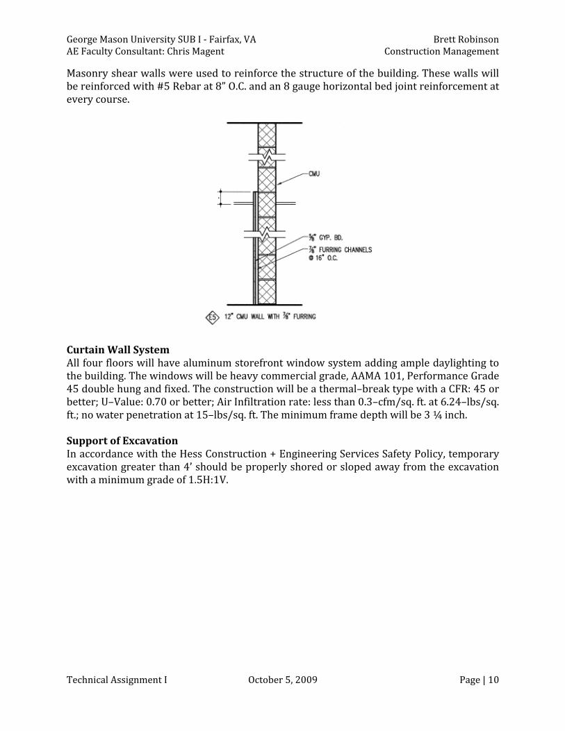
Masonry Floors one through four have similar wall enclosures. The wall system consists of 1/2” gypsum wall board with a 7/8” resilient hat channel. This is followed by 6” CMU and 2” R18 Spray applied insulation. Hot dipped galvanized steel masonry ties secure the brick veneer to the CMU. The brick veneer will consist of a color to balance the brick of the existing Student Union Building and will also have an accent color to complement the exposed horizontal concrete bands of the existing building. Continuous membrane base lashing and weep holes will allow or proper drainage. ff
George Mason University SUB I ‐ Fairfax, VA Brett Robinson
Technical Assignment I October 5, 2009 Page | 10
AE Faculty Consultant: Chris Magent Construction Management
Masonry shear walls were used to reinforce the structure of the building. These walls will be reinforced with #5 Rebar at 8” O.C. and an 8 gauge horizontal bed joint reinforcement at every course.
Curtain Wall System All four floors will have aluminum storefront window system adding ample daylighting to the building. The windows will be heavy commercial grade, AAMA 101, Performance Grade 45 double hung and fixed. The construction will be a thermal–break type with a CFR: 45 or better; U–Value: 0.70 or better; Air Infiltration rate: less than 0.3–cfm/sq. ft. at 6.24–lbs/sq. ft.; no water penetration at 15–lbs/sq. ft. The minimum frame depth will be 3 ¼ inch. Support of Excavation In accordance with the Hess Construction + Engineering Services Safety Policy, temporary excavation greater than 4’ should be properly shored or sloped away from the excavation with a minimum grade of 1.5H:1V.

George Mason University SUB I ‐ Fairfax, VA Brett Robinson AE Faculty Consultant: Chris Magent Construction Management
Technical Assignment I October 5, 20 Page | 11
09
Project Cost Evaluation
Cost Summary
George Mas ity SUB I Costs on Univers Cost Co . st/SQ. FT
Construction Cost* $14,212,337 $251.22 Total Project Cost $17,550,000 $310.21
*Construction Cost excludes land costs, site work, permitting, etc.
Building Systems Cost
George Mason Unive I – Building System s rsity SUB s CostBuilding System Cost Cos T. t/SQ. FStructural Steel $1,250,000 $22.10
Elevators $120,000 $2.13 Mechanical $3,650,000 $64.52
Fire Protection $200,000 $3.54 Electrical $2,025,000 $35.80
D4 Cost Estimate
Please See D4 Cost Estimate in Appendix Page # 4‐5 Using the D4 Cost Estimating Program, a parametric estimate was prepared for the GMU SUB I project. The project was selected based on similarities in type and use of the building, number of floors, project height, and square footage. The total project cost for the D4 estimate was $6,953,836 or $122.92 per square foot. The D4 estimate was $10,596,164 less than the total project cost for the Student Union Building project.
RS Means Cost Estimate
Please See RS Means Cost Estimate Reference in Appendix Page # 6‐7 Using the 2009 RS Means Square Foot Cost Estimate Book, a square foot estimate was prepared for the project. Type M.160 – College Student Union Building was used for this specific estimate.
Building Parameters Area (SF) 56,575
Perimeter (LF) * 4 Floors
564’‐1 7/8”
Avg. Story Height 13’‐10 1/2”

George Mason University SUB I ‐ Fairfax, VA Brett Robinson
Technical Assignment I October 5, 2009 Page | 12
AE Faculty Consultant: Chris Magent Construction Management
Brick face with concrete block back‐up was used in the estimate with a steel structure. Since the largest square footage available was 55,000 sq. ft., that specific cost of $154.45/sq. ft. was used.
Georg Universi Means e n Maso ty SU – RSB I Base Cost/sq. ft. $ 154.45 Per U just nit Ad Notes Height Adjust +$4.59 2.45 Per 1 ft
P erimeter Adjust ‐1.37 1.15 Per 100 LF Subtotal $157.67
Location Factor 0.93 Fairfax, VA Total Cost/sq. ft. $146.64 Additions include:
• 3,500 lb Elevator: +$69,800 ergency Lights: $805 each (185 fixtures)= +$148,925 • Nickel Cadmium Em
Total Cost: $8,499,181.89
The RS Means estimate was $9,050,818.11 less that the total project cost for the Student Union Building project.
Conclusion Both the D4 and the RS Means estimates were around $10 million less than the actual project cost for the GMU project. There are several possibilities for the differing costs.
• tThe project includes a 30,000 sq. ft. mechanical renovation in the existing S udent Union Building.
• xisting and new Student Union Select demolition will be done to connect the e
• Buildings. Geopier systems will be used for deep foundations.
• Extensive site work was done with the relocation of the main transformer, the main transformer, and the relocation of and secondary conduit lines associated with the
the emergency generator.

George Mason University SUB I ‐ Fairfax, VA Brett Robinson AE Faculty Consultant: Chris Magent Construction Management
Technical Assignment I October 5, 2009 Page | 13
Site Plan of Existing Conditions
in Appendix Page # 8 Please See Existing Conditions and Demo Plan Please See Site Plan in Appendix Page # 9‐10
lease See Utilities Layout in Appendix Page # 11 P
The George Mason University Student Union Building I is located on the Fairfax, Virginia Campus. The project is off of Aquia Creek Lane. The project is surrounded by a newly onstructed 3 story Data Center (North), an existing 3 story Student Union Building (West), ca 2 story Student Housing complex (East), and the 1 story Harris Theatre. The item that makes this construction project so unique is that the site is very compact. The site is so tight, there will be no construction parking allowed on‐site. Workers have the ption to pay for a semester log parking spot. George Mason will also allow for on‐campus oconstruction material deliveries for the project at an alternate location if needed. There are two main utilities relocation that will be done. The first is the relocation of the main transformer. This activity will also consist of the installation of main and secondary runs. The second is the demolition and reconstruction of a new HTW tunnel, as stated in the demolition section of the building system section.

George Mason University SUB I ‐ Fairfax, VA Brett Robinson AE Faculty Consultant: Chris Magent Construction Management
Technical Assignment I October 5, 2009 Page | 14
Local Conditions Preferred Methods of Construction in the Region The recent construction around the Fairfax Campus has been a steel superstructure with a brick veneer to complement the other buildings around campus and reflect the character of the university as an institution with a rich past, vibrant present, and promising future. Buildings should be tall enough to define adjoining spaces. This will require a minimum 3‐tory or 45 feet high building. Well‐developed and articulated rooflines are encouraged and oth sloped roofs and flat roofs are accepted. sb Availability for Construction Parking Due to such a confined site, parking is particularly limited on the SUB I construction site. Parking is available in an on‐campus parking lot, for a cost per semester. To alleviate such osts, many subcontractors choose to park in the numerous Fairfax City free parking lots nd carpool to the campus. ca Recycling According to the LEED Scorecard performed by Chris Flaherty of Hess Construction + Engineering Services, Hess plans to divert 93% of the construction waste management. PDS Recycling (Manassas, VA) will pick up the waste. The waste is then taken to a warehouse wned by Broad Run Recycling (Manassas, VA) and sorted to maximize the recyclables. The emaining trash that cannot be recycled is then taken to a landfill. or Soil Report Geotechnical Consulting & Testing Inc. performed a subsurface evaluation by drilling (9) test boring. The borings were at refusal depths from 10 to 40 feet below the ground urface. Soils classified are in accordance with ASTM D2488 “Description and Identification sof Soils” and the Unified Soil Classification System. George Mason University Student Union Building I is located in a Piedmont Physiographic Province. The ground has a rolling upland surface underlying by complexly folded and aulted crystalline rocks. The rocks are generally fine to coarse grained, lustrous, greenish‐fgray, reddish weathering, quartz‐rich schist, and lesser mica schist, phyllite, and gneiss. The existing Student Union Building I is supported on a deep foundation system consisting of drilled piers. The maximum column loads for the building addition are anticipated at 480 kips and maximum wall loads of approximately 1 kip per linear foot. Due to the presence of deep undocumented existing fill, a deep foundation system is recommended for support of he proposed building addition. Based on the subsurface information and anticipated loads
exceed 1/2”. tof the building, the estimated settlement of the 30” geopiers will not Please See Soil Boring Location Plan Diagram in Appendix Page # 12

George Mason University SUB I ‐ Fairfax, VA Brett Robinson AE Faculty Consultant: Chris Magent Construction Management
Technical Assignment I October 5, 2009 Page | 15
Local Conditions Ground Water Conditions Ground water observations were made during the drilling of the test borings by visual examination, upon completion of the drilling, and after a 24 hour period.
Summary of Ground Water Conditions
Boring Number
During Drilling
U ponCompletion
Af 4 ter 2H ours
Approximate Elevation
B‐1 25.0’ 23.0’ 11.0’ EL 411 B‐2 Dry Dry 11.0’ EL 410 B‐3 28.0’ 24.0’ 1 2.0’ EL 410 B‐4 25.0’ 21.5’ 1 5.0’ EL 411 B‐5 38.0’ 29.5’ 8.3’ EL 418

George Mason University SUB I ‐ Fairfax, VA Brett Robinson AE Faculty Consultant: Chris Magent Construction Management
Technical Assignment I October 5, 2009 Page | 16
Client InformationGeorge Mason University has had a rapid growth in all the campuses over the last couple decades. George Mason’s student population has increase to over 18,000 undergraduates. Accompanying the growth has been an increased demand for on‐campus Student Union support and office space at George Mason University develops its educational operation. The addition will house meeting spaces, office, and student service and activity spaces. With this in mind, George Mason University has decided to implement a design‐build process to construct an addition to the existing Student Union Building I. This process will be in accordance with the Commonwealth of Virginia design‐build procedures. At the current time, George Mason University is very familiar with the construction process nd design‐build contracts. Currently, George Mason University has eight construction
aprojects being performed on the Fairfax, Virginia campus. Cost was vital when preparing the design of this building. The university had a $20,627,000 budget slated for this project. Safety is very important for the university. The existing student union building, which is directly next to and will eventually connect to the new SUB I project, will remain open for student and faculty. With construction being performed directly next to this building, as well as all over campus the safety of the students and faculty poses a major issue. When proposing for this project one important aspect of the presentation was the schedule portion. The design‐builders had to propose a thirty activity CPM schedule. This included a description of how the schedule was going to be maintained in addition to, any long lead time items that will come into effect. Finally, quality is another crucial part of this project for GMU. As stated in the RFP, “The University intends to realize a project that meets its requirement for efficient and durable facilities as well as meeting contemporary standards for the student centers for intuitions for higher learning. It is its intension to encourage innovative planning resulting in the enhancement of campus life of students through the design of its facilities and its surroundings.”
To meet the owner’s satisfaction, the master plan delineates a new campus framework to create an academic setting that is compact, rational and readable. Pedestrian “streets”, semi‐enclosed quadrangles, quality open spaces and vistas combine in a coherent whole. The campus framework provides a flexible structure for future campus program elements while creating e sense of place. The framework is comprised of six fundamental elements:
a uniqu
• Arrival
• • rangles Main streets and quad
• rks Connections
a• s
View and LandmNatural system
• Compact Core

George Mason University SUB I ‐ Fairfax, VA Brett Robinson AE Faculty Consultant: Chris Magent Construction Management
Technical Assignment I October 5, 2009 Page | 17
Project Delivery System

George Mason University SUB I ‐ Fairfax, VA Brett Robinson AE Faculty Consultant: Chris Magent Construction Management
Technical Assignment I October 5, 2009 Page | 18
Project Delivery System There are essentially three key players in the project delivery of the George Mason University Student Union Building I project. As stated in the client information section, George Mason University is the owner of this project. All third party inspections are subcontracted out to EMSI Engineering, Inc. The delivery method chosen by GMU itself is Design‐Build. Essentially, all construction that is being performed on the Fairfax Campus is Design‐Build. Hess Construction + Engineering Services is the design builder and Grimm + Parker is the Architect. Hess Construction + Engineering Services was chosen for their ompetitive low bid and expert knowledge in construction in the education field. Grimm + cParker is a key designer in educational facilities in the DC, Maryland, Virginia area. Grimm + Parker performs its design services out of its home office in Bethesda, Maryland. Grimm + Parker has several consultants for each major design portions of the project. This includes mechanical, electrical, life safety, structural, civil, etc. These groups each perform designs of their respected division, code analysis, and preliminary Building Information Modeling.
The trade contractors to Hess Construction + Engineering Services are contracted under u nd were sellump s m a ected through the lowest competitive bid.
Under the Commonwealth of Virginia, a Standard Performance Bond (CO‐10) and a Standard Labor and Material Payment Bond (CO‐10.1) were used between the contractor, surety, and owner. In effort to insure this risk management, Insurance Associates were brought in for this specific task.
Based on George Mason experience with construction and Design‐Build projects and Hess Construction + Engineering Services/Grimm + Parker expertise in their respected educational construction and design, it is assessed that this particular delivery system and contracts are appropriate.

George Mason University SUB I ‐ Fairfax, VA Brett Robinson AE Faculty Consultant: Chris Magent Construction Management
Technical Assignment I October 5, 2009 Page | 19
Staffing Plan

George Mason University SUB I ‐ Fairfax, VA Brett Robinson AE Faculty Consultant: Chris Magent Construction Management
Technical Assignment I October 5, 2009 Page | 20
Staffing Plan This is the typical staffing plan for Hess Construction + Engineering Services. Hess’s main focus is on educational construction in the DC, Maryland, and Virginia areas. This staffing plan shows both the on‐site and in‐home office personnel. The main focus will be on the on‐site staff. This particular staffing plan also is for later in the project. At this current time, the GMU project is still in the early phases of construction.
Project Executive The project executive is responsible for the entire staff for this specific project. Michael is a key contact person between the owner, architect, and the trade contractors’ project managers. Michael attends the weekly owner’s meeting at GMU. With an architecture ackground, Michael has played a vital role in the design process of the Student Union uilding. bB Project Manager The project manager is responsible for the successful completion of the SUB I project. Greg’s main responsibilities consist of writing and reviewing contracts, payment requisitions, and overall preparation of project schedule. Greg also works on preparing ubcontractors’ project procedure, processing change orders, and establishing a schedule f values. so BIM Manager The BIM manager is responsible for the overall BIM process. Saurabh acts as a liaison etween the subcontractor’s BIM/IT personnel. He gathers all the BIM models, compiles he models together, and performs clash detection tests in Navisworks. bt Field Engineer he field engineer is responsible for tracking and distributing RFI’s, reviewing submittal, nd photographing the progression of the project. Ta Superintendent The superintendent is responsible for the coordination between subcontractors on‐site, maintaining the schedule, and creating a look‐a‐head schedule for future construction ctivities. Merrill in charge of quality control observations and maintains quality control hrough detailed daily reports. at

George Mason University SUB I ‐ Fairfax, VA Brett Robinson AE Faculty Consultant: Chris Magent Construction Management
Technical Assignment I October 5, 2009 Page | 21
Appendix
Table of Contents
A. Project Summary Schedule ………………………………………………...…………………1 B. Structural Foundation/First Floor Plan……………………………………………...…2
C. Steel Erection Phasing Plan Diagram………………………………….…………………3
D. D4 Cost Estimate…………………………………….………………………………………....…4 E. RS Means Cost Estimate Reference……………………………….…………………...…6 F. Existing Conditions and Demo Plan...…………………….………………………...……8 . .
G Site Plan…………………...…………………………….……………………………………………9 H Utilities Layout…………...……………………………..……………………………………….11 I. Soil Boring Location Plan Diagram………….…………………………………….....…12

ID Task Name Duration Start Finish1 STUDENT UNION BUILDING I 387 days Fri 1/23/09 Mon 7/19/102 BCOM BUILDING APPROVAL 175 days Fri 3/20/09 Thu 11/19/093 Schematic Design (incl. BCOM Submission) 28 days Fri 3/20/09 Tue 4/28/094 Preliminary Design (100% DD) (incl. BCOM Submission) 54 days Fri 5/1/09 Wed 7/15/095 Working Drawings (100% CD) (incl. BCOM Submission & Re-subm 49 days Thu 6/25/09 Tue 9/1/096 Working Drawing Comments II from BCOM & Re-submission 34 days Wed 9/2/09 Mon 10/19/097 Meeting with BCOM to present re-submission 2 days Tue 10/20/09 Wed 10/21/098 Working Drawings Approval 4 wks Thu 10/22/09 Wed 11/18/099 Building Permit Issued 1 day Thu 11/19/09 Thu 11/19/0910 SITE PLAN, FOUNDATION, SUPERSTRUCTURE APPROVALS 184 days Fri 1/23/09 Wed 10/7/0911 Geotechnical Study/Utility Verification 15 days Tue 3/3/09 Mon 3/23/0912 Site Plan Completion 30 days Fri 1/23/09 Thu 3/5/0913 Verification of infrastructure with Building Design 30 days Tue 3/24/09 Mon 5/4/0914 Submission for Water, Sewer, Storm, E&S, Grading 2 wks Tue 5/5/09 Mon 5/18/0915 Site Plan Approval 4 wks Thu 7/16/09 Wed 8/12/0916 Foundation Permit Approval 4 wks Thu 8/13/09 Wed 9/9/0917 Superstructure Permit Approval 4 wks Thu 9/10/09 Wed 10/7/0918 CONSTRUCTION 323 days Thu 4/23/09 Mon 7/19/1019 Long Lead Equipment Procurement 80 days Thu 4/23/09 Wed 8/12/0920 Site Mobilization/ Pre-Construction/ Site Security 15 days Thu 8/13/09 Wed 9/2/0921 Site Excavation & Foundation Work 30 days Thu 9/3/09 Wed 10/14/0922 MEP Below Grade 10 days Thu 9/24/09 Wed 10/7/0923 Structural Frame 45 days Thu 10/15/09 Wed 12/16/0924 Concrete Slab on Grade & Decks 45 days Thu 10/15/09 Wed 12/16/0925 Set MEP Sleeves/ Duct Penetrations (Deck to Roof) 50 days Thu 10/15/09 Wed 12/23/0926 MEP Risers 15 days Thu 12/24/09 Wed 1/13/1027 Exterior Skin 60 days Thu 11/5/09 Wed 1/27/1028 MEP Main Distribution/ Equipment Installation 40 days Thu 1/28/10 Wed 3/24/1029 Roofing 20 days Thu 12/17/09 Wed 1/13/1030 Interior Finishes 80 days Thu 1/28/10 Wed 5/19/1031 Building Commissioning 21 days Thu 5/20/10 Thu 6/17/1032 Building Addition Substantial Completion 1 day Fri 6/18/10 Fri 6/18/1033 University FF&E Installation 14 days Mon 6/21/10 Thu 7/8/1034 Occupancy of Addition 7 days Fri 7/9/10 Mon 7/19/10
De Ja Fe Ma Ap Ma Ju Jul Au Se Oc No De Ja Fe Ma Ap Ma Ju Jul Au
Task
Split
Progress
Milestone
Summary
Project Summary
External Tasks
External Milestone
Deadline
Page 1
Project: GMU SUB I:Tech 1Date: Sun 10/4/09


