geophysical manual · ultraseismic, seismic wave reflection, transient force vibration, parallel...
TRANSCRIPT

1
GEOHAZARDS FORUM, August 2-3, 2006, Lexington, Kentucky
GEOPHYSICAL MANUALGEOPHYSICAL MANUALA Practical Engineering Solution for Highway Related A Practical Engineering Solution for Highway Related
ProblemsProblems
By:Kanaan Hanna
Geotechnical Engineer
Khamis HaramyGeotechnical Engineer

2
Abandoned Mine VoidsDetection
Presentation FocusPresentation Focus
Geophysical Manual
Part IGeophysical
Workshop
Part II Part II
HIGHHIGH--RESOLUTION GEOPHYSICAL RESOLUTION GEOPHYSICAL TECHNOLOGIES FOR TRANSPORTATIONTECHNOLOGIES FOR TRANSPORTATION

3
Part I & II Part I & II –– BackgroundBackground
Why geophysical imaging technologies have not been fully utilized in engineering
investigations
• Highway engineers are using geophysics,but… Not much confidence
• Blackbox stigme• Processing complexity• Selecting EXPERIENCED geophysical contractor

4
Part I & II Part I & II –– BackgroundBackground
What can geophysics do for Highway Engineer
• Geophysics Engineering Benefit– Reduce cost– Less environmental impact– Better site characterization– Safer and more economical design– Accurate bids– Fewer claims

5
Part I & II Part I & II –– BackgroundBackground
FHWA – CFLHD Initiatives In cooperation with Blackhawk developed two documents…
• Geophysical Manual– A practical engineering solutions for highway related problems
Designed on solving engineering problems using various geophysical methods and techniques
• Geophysical Workshop– Increase confidence and familiarize Highway Engineers with
geophysical technologies for transportation projectsDesigned on using various geophysical methods and techniques
for solving engineering problems

6
Part I – Geophysical Manual
An Overview of the Geophysical Manual
ASTM Standard D6429-99Standard Guide for Selecting Surface
Geophysical Methods
ASTM Standard D420-98 (2003)Standard Guide to Site
Characterization for Engineering Design, and Construction Purposes
ASTM References

7
Chapter 1 Introduction• Purpose• Background• Evaluation of Appropriate Geophysical
Methods (Table 1)
Chapter 2 through 10 in two parts• Part I Engineering Applications – Chapter 2 through 7• Part II Detailed/Theory – Chapter 8 through 10
Bibliography for Part I and IIGlossary – Definitions of terms
Document Organization
Part I – Geophysical Manual

8
Part I – Geophysical ManualEngineering Problem Application Geophysical/NDT Solutions
Unknown Depth of Foundations
Sonic Echo/Impulse Response, Bending wave, Ultraseismic, Seismic Wave Reflection,
Transient Force Vibration, Parallel Seismic, Induction Field, Borehole logging, Dynamic
Foundation Response, Borehole Radar, Borehole Seismic
Integrity Testing of Foundations and Structures
Crosshole Sonic Logging, Crosshole Sonic Logging Tomography, Gamma-Gamma Density
Logging, Singlehole Sonic Logging, Sonic Echo/Impulse Response, Ultraseismic Profiling, Ultrasonic Pulse Velocity, Impact Echo, Ground Penetrating Radar, Spectral Analysis of Surface
Waves, Acoustic Emissions, Radiography
Rebar Quality and Bonding Half-cell Potential, Linear Polarization
Resistance, Galvanostatic Pulse Technique, Electrochemical Noise, Acoustic Emissions,
Magnetic Field Disturbance
CHAPTER 2 -
BRIDGE SYSTEM SUBSTRUCTURE
Foundation Scour Time Domain Reflectometry, Parallel Seismic, Ground Penetrating Radar, Continuous Seismic
Reflection Profiling, Fathometer
Bridge Deck Stability New Decks
Baseline Assessment
CHAPTER 3 -
BRIDGE SYSTEM SUPERSTRUCTURE Existing Decks
Vibration Monitoring, Ground Penetrating Radar, Electromagnetic, Impact Echo, Spectral
Analysis of Surface Waves and Ultrasonic Surface Waves Methods, Half-Cell Corrosion
Potential Mapping, Infrared Thermography
QA/QC Of New Pavements Existing Pavements CHAPTER 4 -
PAVEMENTS Transportation / Geotechnical
Methods
GPR, Impact Echo, Spectral Analysis of Surface Waves, Ultra Sonic Surface Wave (USW), Multichannel Analysis of Surface Waves
(MASW)
Mapping Voids, Sinkholes, Abandoned Mines, and Other
Cavities
Gravity, GPR, Resistivity , Seismic Refraction, Seismic Reflection, Rayleigh Waves Recorded with a Common Offset Array, Cross-borehole
Seismic Tomography CHAPTER 5 -
ROADWAY
SUBSIDENCE Roadbed Clay Problems
Conductivity Measurements, Resistivity Measurements, Time Domain Electromagnetic
Soundings, Induced Polarization
Mapping Bedrock, Lithologies, Sand & Gravel
Deposits, Groundwater Surface, and Flow
Ground Penetrating Radar, Seismic Refraction, Compressional and Shear Wave Reflection, Resistivity, Time Domain Electromagnetic,
Conductivity Measurements, Spectral Analysis of Surface Waves, Gravity, Very Low Frequency Electromagnetic, Borehole Televiewer, Induced
Polarization, Borehole Gamma and HydroPhysical Logging, Nuclear Magnetic Resonance, Self Potential, Electroseismic
Determining Engineering Properties and Rippability of
Soil and Rock
Seismic Refraction, Nuclear Magnetic Resonance, Ground Penetrating Radar, Spectral
Analysis of Surface Waves, Suspension Logging, Full Waveform Sonic Logging, Crosshole Shear
CHAPTER 6 -
SUBSURFACE CHARATERIZATION
Utility Locator, Detecting Underground Storage Tank,
UXO and Contaminant Plums
Magnetic, Electromagnetic, Ground Penetrating Radar, Acoustic Pipe Tracer, Metal Detectors,
resistivity, Induced Polarization, Refraction
CHAPTER 7 -
VIBRATION MEASUREMENTS
Vibration Caused By Traffic, Construction, and Blasting
Vibration Monitoring
Table 1 Document
Organization

9
Geophysical Manual Available Formats
• Hard copy – one volume, 742 pages, with 400 figures
• Adobe Acrobat File (pdf) on CD (available from Blackhawk)
• Online at the FHWA, CFLHD local site @ the following url:
http://www.cflhd.gov/geotechnical
Part I – Geophysical Manual

10
Navigation through the web site
Part I – Geophysical Manual
SplashSite

11
SOLUTION MATRIXSOLUTION MATRIX
PART IIGEOPHYSICAL METHODS/THEORIS
PART IIGEOPHYSICAL METHODS/THEORIS
The web Manual is designed with a Solution Matrix to guide the user for specific applications
PART IENGINEERING APPLICATIONS
PART IENGINEERING APPLICATIONS
Part I – Geophysical Manual

12
PART I – Problem/Application
Part I – Geophysical Manual
ENGINEERING APPLICATIONSENGINEERING APPLICATIONS
BRIDGEBRIDGE
PAVEMENTSPAVEMENTS
ROADWAYSUBSIDANCEROADWAY
SUBSIDANCEVIBRATION
MONITORINGVIBRATION
MONITORING
VoidsVoids ClayClay
SinkholesSinkholes
Abandoned Mines
Abandoned Mines
CavitiesCavities
SUBSURFACECHARACTARIZATION
SUBSURFACECHARACTARIZATION
13
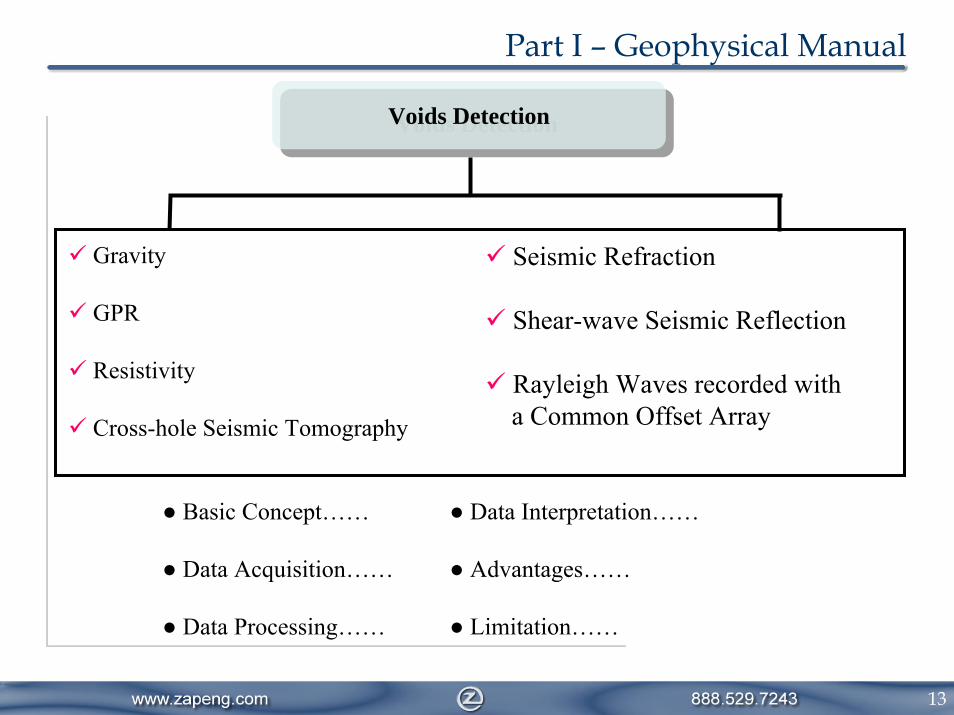
Voids DetectionVoids Detection
Part I – Geophysical Manual
Gravity
GPR
Resistivity
Cross-hole Seismic Tomography
Seismic Refraction
Shear-wave Seismic Reflection
Rayleigh Waves recorded witha Common Offset Array
● Basic Concept…… ● Data Interpretation……
● Data Acquisition…… ● Advantages……
● Data Processing…… ● Limitation……

14
PART II – Detailed/Theory
GEOPHYSICAL METHODSGEOPHYSICAL METHODS
GEOPHYSICALQUANTITIES
GEOPHYSICALQUANTITIES
SURFACEMETHODS
SURFACEMETHODS
BOREHOLEMETHODS
BOREHOLEMETHODS
Part I – Geophysical Manual

15
Part II – Geophysical Workshop
FHWA – CFLHD Initiatives In cooperation with Blackhawk developed two documents…
• Geophysical ManualDesigned on solving engineering problems using various geophysical
methods and techniques• Geophysical Workshop
Designed on using various geophysical methods and techniquesfor solving engineering problems

16
Geophysical Summaries
Engineering Benefit
Geophysical ManualFeature Comparison Matrix
Method Briefs
VoidsClay
Seismic ReflectionSeismic Refraction
SASWMASW
Crosshole Seismic
Electrical ResistivityTDEMFDEM
Magnetics
GPR
Part II – Geophysical Workshop
An Overview ofGeophysics
Case Studies
Choosing a Geophysical Contractor Summary

17
Geophysical Summaries
Engineering Benefit
Geophysical ManualFeature Comparison Matrix
Method Briefs
VoidsClay
Seismic ReflectionSeismic Refraction
SASWMASW
Crosshole Seismic
Electrical ResistivityTDEMFDEM
Magnetics
GPR
Part II – Geophysical Workshop
An Overview ofGeophysics
Case Studies
Choosing a Geophysical Contractor Summary

18
Method Brief
Basic Principles
Instrumentation
Data Examples
Field Surveys
Limitations
Advantages
Seismic Refraction
Seismic Reflection
Crosshole Seismic
Ground Penetrating Radar
Electrical Resistivity
Electromagnetic (TDEM/FDEM)
Magnetics
SASW / MASW
Geophysical Summary
Part II – Geophysical Workshop
Methods

19
Seismic RefractionTaylor River Road, CO (FHWA, CFLHD)
Part II – Geophysical Workshop

20
Loose-Medium dense silty SAND
Medium dense-Dense silty SANDS with Cobbles, boulders and rock fragments
Granite, moderately weathered
Highly fractured rock, granite/mica schist
300 m/s
500 m/s
600 m/s
700 m/s
800 m/s
900 m/s
1,000 m/s
1,100 m/s
400 m/s
Vel
ocity
Sca
le
Assumed Competent rock
Velocity Scale, m/s
300 1,100Softer Harder
Seismic RefractionData Example: Mapping Bedrock Seismic Refraction Tomography
Part II – Geophysical Workshop
-2020 10 -10Distance, m
2,700
2,680
2,690
2,695
2,685
Elev
atio
n, m
-15- 5515
Boring

21
Tow Vehicle and EM31-3 Array System
GPS
Frequency Domain Electromagnetics (EM)
Part II – Geophysical Workshop
Geophysical data integrated with GPS dataData acquisition speed ~ 10MPHTotal surveyed area ~ 34 milesField days ~ 4Soil boring performed during and after survey

22
Data Profiles provide limited information
EM38
Distance, m
80
40
100
EM31
Con
duct
ivity
, mS/
m
0MM46
EM Data PresentationFrom Physics to Engineering Data
P&P drawings provide optimum information
Part II – Geophysical Workshop

23
GEOPHYSICAL VOID DETECTIONDEMONSTRATIONS
Part III – Abandoned Mine Voids Detection
• Seismic Reflection•P-waves•S-wave
• Cross-hole tomography• Guided waves• RVSP• Sonar mapping

24
• Unknown mines,• Inaccurate historical mine maps, or• Incomplete historical mine maps
MSHA Old mine works present major H&S hazards to our nation’s miners…
DOT’s Abandoned mines beneath roadways impact the performance of transportation infrastructure in terms of…• Cost,• Public safety
Part III – Abandoned Mine Voids Detection

25
Criterion HRPW HRSW XHT GuidedWaves RVSP Sonar
Mapping*
Ability to LocateMine Works/Voids Fair Fair Poor Poor Good n/a
Resolution Poor Poor Poor Very Poor Very Good Excellent
Depth ofInvestigation Good Poor Good Good Good Very Good
AnticipatedRepeatability Good Fair Good Fair Good Very Good
Robustness underVariousGeologic/SurfaceConditions
Fair Poor Fair Fair Good Very Good
Cost High Very High Medium Low Medium Medium
Void Contents Poor Good Poor Poor Good Very Good
*Sonar mapping can only be used in a borehole that has intersected a water-filled void in the mine.
Performance Evaluation of Geophysical Methods
Part III – Abandoned Mine Voids Detection

26
HRS Data Analysis and InterpretationAnomalous Coal Response from P-wave
Part III – Abandoned Mine Void Detection

27
RVSP Data Analysis and InterpretationSeismic Amplitudes from RVSP Profiles along the Target Zone
Part III – Abandoned Mine Voids Detection
28
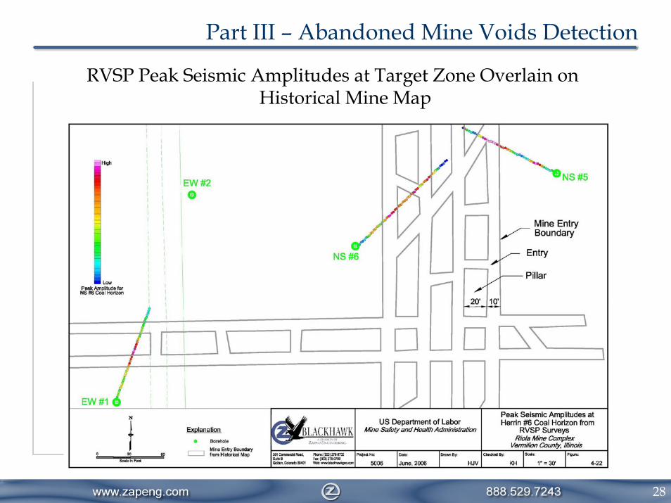
RVSP Peak Seismic Amplitudes at Target Zone Overlain on Historical Mine Map
Part III – Abandoned Mine Voids Detection

29
Void Confirmation through Drilling and Sonar Mapping
Part III – Abandoned Mine Voids Detection

30
Part III – Abandoned Mine Voids Detection
RVSP Application for Planned Development Site, Erie, CO

31
• xxx
Part III – Abandoned Mine Voids Detection
RVSP Peak Seismic Amplitudes at Target Zone Overlain on Historical Mine Map

32
Thank You

33
Training Material for Workshop on
Geophysical Methods for Transportation Applications
February 25, 2005
FHWA Resource Center
Geophysical Summaries
Case Studies
Engineering Benefit
Summary
Choosing a Geophysical Contractor
Method Briefs
Feature Comparison Matrix
OverviewTable of Contents
Part II – Geophysical Workshop

34
Feature Comparison Matrix
FeatureGeophysical
MethodAdvantages Limitations
i
-GPR Shallow voids only
Data recorded quickly and displayed on screen in during field acquisition
Antenna frequency changed quickly to either enhance resolution or penetration
Success is very site specific
Depends on a contrast in dielectric properties between thetarget and host
Any metal features may hinder surveyy
Resistivity Quite successful at imaging large shallow voids
Voids have a high resistivity
Best suited for finding shallow voids, 20 to 30 m depending on geology and void size
A 1 to 2 ratio is necessary for electrode arrays. A 40 ft deepvoid would require an 80 foot electrode spacing, which may not be efficient
Seismic Refraction
Rapid to apply in the field
Seismic refraction records are displayed on the instrument allowing potential fractures to be recognized during the field surve y
This method is indirect as it detects fractures and not voids
Voids may be detected if they are not too far beneath the bedrock
Fractures may not be related to a void and have some other origin
Shear -wave Seismic Reflection
Success depends on the f requency of shear waves in the ground
If high frequencies can be generated, small voids can be detected
Shear wave reflection is labor intensive
Requires extensive processing
Few sources exist for shear wave propagation
Voids, sinkholes,abandoned mines’karst
Crosshole Tomography
Tomograph y provides a high - resolution 2D or 3D volumetric image between two boreholes
Can image the entire length of the borehole
No diminishing returns with depth
Tomography is data intensive
Specialized 3D software is required for true 3D imaging
Artifacts c an be present due to limited ray coverage near image boundaries
Feature Comparison MatrixPart II – Geophysical Workshop
Voids, Clay, Bedrock Depth/Fracture, Faults, Lithology, Sand and Gravel, Utilities, UST, Plumes, UXO

35
Penetration
and Resolution
Horizontal Resolution
Dep
th/V
ertic
alR
esol
utio
n
Pen
etra
tion
Ground/Structure Surface
Key Geophysical Concepts – Contrast
Part II – Geophysical Workshop
High-Resolution GPRVoid Detection

36
Part III – Abandoned Mine Voids Detection Methodology A systematic approach – integrating 2-D and/or 3-D geophysical investigations with subsidence/geotechnical engineering evaluation for optimum foundation design…
Geophysics Subsurface Investigation:• Identify old mine works• Identify mine voids
Engineering GeophysicsSubsurface Characterization in terms of:• Subsidence evaluation• Void detection evaluation
Engineering Evaluation
Engineering Analysis:• Geotechnical evaluation• Foundation system evaluation and risk assessment• Engineering decision