geophysical characterization of subsurface barriers eie!iel · textbooks and publications (example...
TRANSCRIPT

SANDIA REPORTSAND95-1461 ● UC–721Unlimited ReleasePrinted August 1995..
RECORDCOPYei
Geophysical Characterization ofSubsurface Barriers
111111111111
EiE!iElDavid J. Borns
Prepared bySandia National LaboratoriesAlbuquerque, New Mexico 87185 and Livermore, California 94550for the United States Department of Energyunder Contract DE-AC04-94AL85000
Approved for public release; distribution is unlimited.
“.
. .
SF2900Q(8-81 )

..
.
Issued by Sandia National Laboratories, operated for the United StatesDepartment of Energy by Sandia Corporation.
NOTICE: This report was prepared as an account of work sponsored by anagency of the United States Government. Neither the United States Govern-ment nor any agency thereof, nor any of their employees, nor any of theircontractors, subcontractors, or their employees, makes any warranty,express or implied, or assumes any legal liability or responsibility for theaccuracy, completeness, or usefulness of any information, apparatus, prod-uct, or process disclosed, or represents that its use would not infringe pri-vately owned rights. Reference herein to any specific commercial product,process, or service by trade name, trademark, manufacturer, or otherwise,does not necessarily constitute or imply its endorsement, recommendation,or favoring by the United States Government, any agency thereof or any oftheir contractors or subcontractors. The views and opinions expressedherein do not necessarily state or reflect those of the United States Govern-ment, any agency thereof or any of their contractors.
Printed in the United States of America. This report has been reproduceddirectly from the best available copy.
Available to DOE and DOE contractors fromoffice of Scientific and ‘lkchnical InformationPO Box 62Oak Ridge, TN 37831
Prices available from (615) 576-8401, I?TS 626-8401
Available to the public fromNational Technical Information ServiceUS Department of Commerce5285 Port Royal RdSpringfield, VA 22161
NTIS price codesPrinted copy: A03Microfiche copy: AO1
;-.
,,

SAND95-1461Unlhnited Release
Printed August 1995
DistributionCategory UC-721
GEOPHYSICAL CHARACTERIZATION OF SUBSURFACEBARRIERS
David J. BornsGeophysics Department
Sandia National LaboratoriesAlbuquerque, NM 87185-0750
ABSTRACT
An option for controlling contaminant migration from plumes and buried waste sites isto construct a subsurface barrier of a low-permeability material. The successfid applicationof subsurface barriers requires processes to verifj the emplacement and effectiveness ofbarrier and to monitor the performance of a barrier after emplacement. Non destructiveand remote sensing techniques, such as geophysical methods, are possible technologies toaddress these needs. The changes in mechanical, hydrologic and chemical propertiesassociated with the emplacement of an engineered barrier will affect geophysicalproperties such a seismic velocity, electrical conductivity, and dielectric constant. Also,the barrier, once emplaced and interacting with the in situ geologic system, may affect thepaths along which electrical current flows in the subsurface. These changes in propertiesand processes facilitate the detection and monitoring of the barrier. The approaches tocharacterizing and monitoring engineered barriers can be divided between (1) methodsthat dhectly image the barrier using the contrasts in physical properties between the barrierand the host soil or rock and (2) methods that reflect flow processes around or throughthe barrier. For example, seismic methods that delineate the changes in density andstiffhess associated with the barrier represents a direct imaging method. Electrical selfpotential methods and flow probes based on heat flow methods represent techniques thatcan delineate the flow path or flow processes around and through a barrier. To some

extent, most of the geophysical methods, such as seismic, electromagnetic, and electricalimaging, discussed in this report can be configured either to address dkect imaging orprocess detection. Flow probes based on heat flow methods possibly can addressmonitoring issues if the longevity of subsurface probes is significantly increased.
Of the two approaches, direct imaging addresses requirements for the verification anddelineation of a barrier. However, direct imaging is impacted by the limits of resolution.Due to scale, time-dependency and dktribution of variations in material properties of soilsand barriers, direct imaging methods may have difficulty in achieving the requiredresolution (the order of 1 to 10 cm). The variation in material properties, such as seismicvelocity and electrical conductivity, due to variations in saturation has major effects on theachievable resolution relative to the effects of technology of the imaging method and itsinstrumentation. The development of geophysical source and receiver technology and thedevelopment of data processing and interpretation methods utilizing evolving computersystems will not alone sufficiently increase the resolution of the geophysical methods. Anunderstanding of the physical processes, such as time dependent moisture migration infingers, within the vadose zone and processes, such as the chemical evolution of porefluids associated with the emplacement of a barrier, is critical. The understanding derivedfrom these studies permits the effects of these processes on geophysical properties to beaccounted for in the final images.
Direct imaging methods also address requirements for the monitoring of barrierpefiormance. Multiple images taken over time can be effective in removing originalvariations in physical properties. Methods, such as electrical imaging and self potentialarrays, that detect flow processes and flow paths, offer an alternative approach. Thesemethods can detect whether flow is occurring around or through a barrier. Similarmethods have to been used to detect flow through earthen dams and leaks in lined storageponds. Such methods will not map the continuity of a barrier within the resolutionrequirements of many site operators, but will provide a means to measure and monitorperformance of a barrier. This monitoring capability can address post-closure compliancewith a regulatory standard.
. .,
.,
ii

TABLE OF CONTENTS
ABSTRACT ........................................................................................................................................ i
TABLE OF CONTENTS...
................................................................................................................ m
LIST OF FIGURES...
......................................................................................................................... Ill
INTRODUCTION ............................................................................................................................. 1
IWWOUS EVALUATIONSOF GEOPHYSICALIUETHODS... ... .......... ............. .......... ........ ....... .. ..... ...... ........ . 1
APPROACHOFmm REPORT..................................................................................................................1D~CW~ONOF~SSmW BmW~EWUCE~~ W~ODS ........... .. ....... ........ .. ..... ...... ........ .......3
Criteria for Barrier material from Heiser, etal. (1994) ....... .. ............. ........ ....... .. ..... .. ..... ....... .........3Frozen Barrier ................................................................................................................................3Physical Description ofBawiers .....................................................................................................4
EmmcnxOFBARRIERSON~ PHYSICALPROPERTIES MEASUREDBY GEOPHYSICALIVWIMODS. ...... .. ......5RELATIONSHIPBETWEENGEOPHYSXCALMETHODSN PHXWCALPROPERTIESOF Sores M RocKs .... ...8
Sismic Methoa%.............................................................................................................................Electromagnetic Imaging ..............................................................................................................l.Electrical Imaging ........................................................................................................................ 11
~~ODShC~OWmS ~ATmDWSB.ER*PUCAnONS: ....... .. ........ .. ..... .. ..... .. ..... .. ..... ........l4
WOL~ON~mS LI~AmONS ... ........ .. ........... ... ............ .............. .. ........ ......... ....... ....... ........ ........l6Chemical Waste Landfill: An example of the limitations of resolution .......................................... 19
SUMMARY ..........................................................................................................................................Recommendations .........................................................................................................................z
REFERENCES ................................................................................................................................ 29
LIST OF FIGURESFIGURE1:CONCEPTUALBARRIEREMPLACEMENT................. .. ........... ... ............ .. ......... ....... ....... ....... .. ....... .2
FIGURE2. THE smtu~ OFFROZENson+SHOWINGTHEcomm’uous LAYEROFADSORBEDWATERONMINERALGRAINS(FROMKING,ETAL.,1988) .....................................................................................4
FIGURE3:CONCE~. CROSS.SE~ON OF SnSWACE GRO~B~R ........... ........ ...... ........ ...... ..... .. ...5FIGURE4: POSSIBLECONFIGURATIONFORELEC~CAJ-MO~O~G SYS~M ....... ....... ....... .. ..... ....... ....... ...12
FIGURE 5: POSSIBLECONFIGURATIONFORELECTROMAGNETICORSEISMICSYSTEMFORMONITORINGORCHARACTERIZATION........................................................................................................................12
FIGURE6: THERELATIONSHIPBETWEENSOILSATURATIONM ELECTRICALCONDUCTIWIYFORAmxcfiSANDYSOILOFTHECHEMICALWmm LANDFILL(ASSUMING30°/0POROSITYw ARANGEOFSATURATIONFROM0.6TO0.8).A CHANGEINSATURATIONFROM 0.7 TO0.6 WOULD RESULTINAREDUCTIONINCONDUCTIVITYFROM0.013 TO0.010 S-M,WHICHISON THEORDEROFTHEOBSERVEDCONTRASTSINTHEELECTROMAGNETICIMAGESOFTHESITE.............................................................20
FIGURE7 (~ B,c): ATTENUATIONOFELECTROMAGNETICMETHODSM ALIMITATIONOFm? METHODS.....21FIGURE.7A ATIINUATIONFOR150OHM-MSOKATFOURFREQUENCIESSPANNINGm RANGE UTILIZEDBY
cURRENTGROUNDPENETRATINGRADAR (GPR) SYSTEMS. .......... ... ........... .. ..... .. ..... ....... .. ..... ....... .....21
FIGURE. 7B :ATI’ENUATIONFOR 100 OHM-MSOILATFOURFREQUENCIESSPANNINGTHERANGE UTILIZEDBYCURRENTGROUNDPENETIWTINGR4DAR (GPR) SYSTEMS. ......... ............. .. ......... ...... ....... .. ..... ....... .. ..22
FIGURE. 7C :AITIWUATIONFOR50OHM-MSOLATFOURFREQUENCIESSPANNINGTHERANGEUTILIZEDBYCURRENTGROUNDPENETRATINGRADAR(GPR) SYSTEMS. ....... .. ...... .......... ..... .. ........ ....... ....... .. ..... ...22
...111

TABLE5: LIMITSON RESOLUTION;FUNGE OFSEISMICVEIJXXITESAND WAVELENGTHSINUNCONSOLIDATEDSEDIMENTS.....................................................................................................................................23
FIGURE8:LIMITSOFSEISMICRESOLUTIONFORDIFTERENTFREQUENCIESAND SEDIMENTTYPES...................23FIGURE9A EFFECTSOFSURVEYASPIX!TRATIOONRESOLUTION.................................................................24FIGURE9B:EFFECTSOFSUBSURFACEHETEROGENEITIESONRESOLUTION...................................................24
:.
.%
iv

INTRODUCTION
An option for controlling contaminant migration from plumes and buried waste sites isto construct a subsurface barrier of a low-permeability material (Heiser, et al., 1994). Thisbarrier could either be “interim” or “permanent”. In concept, the “interim” barrier canprovide time for the evaluation and selection of remediation options. The “permanent”barrier would be a component of the engineered landfill or containment system and wouldhave to meet some performance goal to reduce subsurface movement of fluids. Therequirement arises of how to veri& the emplacement and effectiveness of the barrier andto monitor the barriers’ performance after emplacement. Non-destructive and remotesensing techniques, such as geophysical methods, are possible technologies to addressthese needs.
Previous Evaluations of Geophysical Methods
Both DOE and EPA have sponsored several evaluations of geophysical methods asapplied to environmental problems (example giveq Olhoeft, 1988, Calef and VanEeckhout, 1992). These evaluations give guidance as to the applicability of variousgeophysical methods, such as seismic, electrical, and electromagnetic, to different siteconditions and targets. As already stated, geophysical methods represent importantpossible characterization and monitoring technologies. Detailed descriptions ofgeophysical methods that could be applied to subsurface barriers are available in severaltextbooks and publications (example given, Telford, et al., 1978; S. H. Ward, 1990).Heiser (1994) summarized geophysical methods that could be applied specifically tobarrier emplacement.
Actual field demonstrations of geophysical methods as applied to barrier emplacementhave occurred. Voss, et al., (1994) report for a grout barrier emplacement in arid alluvialsoils that (1) borehole electrical and moisture logging during and after grout emplacementshow a decrease in resistivity and increase in moisture content at the emplacementhorizon, and (2) for this site, ground penetrating radar (GPR) was not effective in manylocalhies due to attenuation with depth and near surface clutter or objects. At the samearid alluvial site, Dwyer (1994) obtained similar results with an overlapping set ofgeophysical methods: ground penetrating radaq surface electromagnetic induction;downhole electromagnetic induction; downhole neutron probe; and downhole temperaturelogs.
Approach of this Report
The approach taken in this report is not to supply a summary of methods (see Heiser,1994) or a tutorial on geophysical methods, which can be obtained from, for example,Telford, et al., 1978 and S. H. Ward, 1990. The approach herein will be to:

. Describe possible barriers and emplacement methods
. Desctibe howthebatiers maytie~the physical propetiies measured;
. Describe what the methods measure and howthese measurements relate tothephysical properties;
. Identi& methods/technologies toaddress three basic tasks:Process control during barrier emplacementVer@ing barrier emplacement
Monitoring barrier pe~orrnance post emplacement● Describe resolution; and● Describe other limits of peflormance
This approach will focus primarily on geophysical imaging methods, for example,ground penetrating radar or electrical, electromagnetic, and seismic tomography. Theseimaging methods permit mapping of subsurface geophysical properties over broad regionswhile minimizing the number of boreholes that may affect the barrier. Therefore, chemicaltracer methods (Heiser, 1994) and borehole logging methods (such as neutron logging)are given minor consideration. The logic for this narrowed focus is in part that: (1) tracermethods, except radioactive, are not actually geophysical methods, and are covered inother studies (e.g., Heiser, 1994); (2) borehole logging methods interrogate only a regionseveral borehole radii or less around a borehole and the boreholes, unless already existingfor chemical monitoring, may affect the pefiormance of the barrier. The borehole loggingmethods are also described in textbooks, such as Hearst and Nelson (1985).
I 1storageTank
Figure 1: Conceptual Barrier Emplacement
.

Description of possibie barriers and emplacement methods
The commonly envisioned approach (Heiser, et al., 1994; Johnson et rd., 1984) is toemplace the barrier in an excavatio~ such as a trench or through a borehole method, suchas jet grouting and permeation grouting (see Figure 1). There is a general relationshipbetween permeability and groutabiiity; and the ability of a grout to penetrate an earthmaterial and form a barrier is a fbnction of viscosity. Earth materials with higherpermeability require higher viscosity grouts to forma barrier. The criteria and possiblematerials for these barriers are listed below:
Criteria for Barrier materiai from Heiser, et ai. (1994)
a) As low an effective difisivity as is reasonably achievable to minimize orinhibh transport of moisture and contaminants
b) Prefer to use conventional emplacement techniques (for example, jet grouting,permeation grouting, trenching)
c) Low permeability, resistance to aggressive chemicals. Special: radiation andthermal resistance
d) Possible binders: polyester styrenes, vinylsester styrenes, high molecularweight acrylics, sulfbr polymer cement, polyacryiic acids, bitume~ and &riirl-aicohol based tl.wanpolymer
e) Aggregates of recycled glass stone, sand and natural soils
f) Effective control of the cure time that allows placement of the barrier butdoesn’t permit the grout to slump due to gravity loading
Frozen Barrier
The use of refrigeration for the freezing of soils and other geologic materials has beenemployed in large-scale engineering projects to give load-bearing strength duringfoundation constructio~ to seal subsurface structures against groundwater flooding, andto stabilize geologic’materials during excavation. This engineering technology is proposedas method to prevent contaminant migration from storage tanks and disposal areas, suchas landfilis, trenches and pits. This frozen barrier will be formed by a network ofunderground piping in which a refi-igerant (for example, caicium chloride brine) wili becirculated. The barrier is formed by the conversion of water to ice in the pore space of thegeologic material. The effectiveness of the frozen soii will in part be a fi.mctionof thesaturation state of initial material and the distribution of soiid, gas and liquid phases ofwater in the pore space. An analog for the physical properties of the frozen barrier ispermafrost soil (King, et ai., 1988). This study looked at the seismic and electricalproperties of unconsolidated permafrost. In this analog, an important observation is that acontinuous unfrozen layer of water remains absorbed on the mineral grains of the soil(Figure 2). The remaining unfrozen water will increase in salinity and, therefore, decreasein electrical resistivity. Seismic velocities of perrnafiost decrease as a fi.mctionof porosityand the water-to- ice ratio. The physical properties of the frozen soil will vary with the

temperature attained during freezing (for example, the resistivity of the soil varies by afactor of five to ten from -2° to -15?
!. ..
Figure 2. The structure of frozen soil, showing the continuous layer of adsorbedwater on mineral grains (from King, et al., 1988)
Physical Description of Barriers
Post test samples of subsurface barriers (for example, Dwyer, 1994) show that theinjected grout initially enters the pore space of the soil (Figure 3). Subsequent injectionsbecome displacive with a grout monolith forming around injection sites or lines. Furtherinjections result in the fracturing of the monolith followed by filling of the fractures withgrout. The dimensions of the grouted zone vary along the length of the injection line andaway from the line.
New approaches are proposed to produced a more continuous and homogeneousbarrier in the subsurface. An example of such a new technology is the “soil sav/’ asproposed by Halliburton. In this technology, a line of water jet cutters and following groutinjectors is moved through the soil along a single slant borehole or between twoapproximately perpendicular directionally drilled boreholes. The effects of this systeminteracting with a heterogeneous geologic environment remains to be demonstrated.Certain effects, such as the introduction of water and grout, may have pronounced andlocal effects on soil properties.

mixedzonewheregroutentersporsspace
/\
monolithicgroutinfillingfracturesaroundinjectionpoint
inje”dionpoint\/
fracturedgroutmonolithFigure 3: Conceptual Cross-Section of Subsurface Grout Barrier
Effects of Barriers on the Physical PropertiesMeasured by Geophysical Methods
The emplacement of a barrier will change the physical behavior and properties ofintegrated host material in several ways. In part, the effects are based on the mode ofemplacement, the material emplaced and the nature of the host material. These changes inphysical properties are what makes the barrier detectable or capable of being monitored.Table 1 lists possible changes in material and hydrologic properties due to barrieremplacement. From this list, possible properties to be used for geophysical detection canbe identified. In Table 2, the possible relationships of barrier materials and installation tochanges in soil and geophysical properties are listed. These tables demonstrate that barrierinstallation can result in material and hydrologic changes that are detectable bygeophysical methods. The questions remaining are the limits of resolution of the variousgeophysical methods and the magnitudes of change in soil and chemical propertiesrequired to be detectable by the various methods.
Some of the observed effects of barrier emplacement maybe counter-intuitive. Forexample, with the reduction in permeability it has been suggested that a barrier leads to anincrease in apparent resistivity. However, the barrier emplacement may actually result in adecrease in resistivity (for example, Heiser, et al., 1994; and Dwyer, 1994). This resultmay rise from several processes that affect electrical properties especially in the vadosezone. One is that the emplacement of the grout includes water as a transport medium or asa byproduct of the chemical reactions occurring after emplacement. Frozen barriers mayalso collect water relative to the surrounding unsaturated host material. Portions of thiswater may remain unfkozen along grain boundaries and promote the flow of electricalcurrent (King, et al., 1988).
5

~. Mater&d D?OD&”t?S. .a) densityofintegratedhostmaterial-barriersystemb) bulkmodulusof integratedhostmaterial-barriersystemc) electricalproper&ies
(1) c&ductivity(2) dielectricconstant(3) conductivityofporefluidorfilling
d) thermal conductivity2. Hy&ologicpropertiesfor example,barriermaterialentersporesandfracturesthusdecreasing
eflectiveporosityandpermeability)
a) effectiveporosityb) saturationc) permeabilityd) relativepermeabilityto gasandliquide) tmtmsilv
rable2:Howbarriermaterials,soilproperties,andgeophysicalpropertiesare relatedEmplacedin sand,silt,claymixtures,saturatedandunsaturatedBarrierMaterial PossibleChange in Local Soil GeophysicalProperties
Proyrties Affected---- —--- --—- -.-— -. -- —-- ——--- ——-——-. .- —-- --——- --——- ---—:ementitous 1ZiTness- I seismicmethods-
1shearmodulus I velocity~bulkmodulus
II attenuation
I II I
phaseI electricalconductivity- I electricalmethods-
1~permeability I conductivityI m~tion I selfpotential~effectiveporosity ~electromagneticmethods-1 II
attenuationI I phaseI II velocityI I conductivity
———- ---- —--- -——- -—syntheticpolymers
-————- ---- --—— --——hydrocarbonwaxes
-- —-- --——— --——- --—stiffness- f;~~;::~~:-=s=----shear modulus I
I velocitybulk modulus I attenuation
I phaseelectricalconductivity- I electricalmethods-permeability I
I conductivitysaturation I self potentialeffectiveporosity ~electromagneticmethods-dielectricpropertiesof pores I attenuation
II phaseII velocityI conductivity
dielectricconstant,—--- —-——--—- -—-———stifTness-
;–.––.––-–--–---–--–-I selsrmcmethods-
.
3
6

.—— —————. . ---- —-- ---- ---- ---- ---- -—— ---- ---— ---- -----———————————— 1
IIIIIIIIIIIII1iIIIIIII
shear modulus i velocitybulk modulus I
Iattenuation
I phaseelectricalconductivity- : electricalmethods-permeability 1 conductivitysaturation I
i selfpotentialeffectiveporosity I electromagneticmetlmds-dielectricpropertiesof pores ~ attenuation
II phaseI velocityII
conductivityI dielectriccmstantIIII
----- ----- ----— ---lowtemperaturethermal
f&-e;5-------------- f;g~;~;.&:---------
I shear modulus II I
velocityI bulk modulus I attenuationI II I phaseI electricalconductivity- I electricalmethods-
1~ permeability I conductivityI saturation I selfpotentialII effectiveporosity ~electromagneticmethods-1 II I
attenuationI I phaseI II I velocityI I conductivityI I
7

Relationship between Geophysical Methods and Physical Properties ofSoils and Rocks
Heiser (1994) summarized geophysical methods that are candidates for characterizingsubsurface barriers. He also provided several case histories. Built upon Tables 1 and 2, theapproach of this report is evaluate how the actual properties afl’ectedby barrieremplacement relate to the distinct families of geophysical methods (i.e., seismic methodsand electromagnetic methods). Table 3 provides the linkage from the geophysical methodto the hydrologic and material properties that are directly and indirectly measured by themethod. This table is followed by several sections describing the basic principles of a givenfamily of geophysical methods and existing applications of these methods to projectssimilar in technical needs as barrier emplacement.
Zizb123:the linkage from the geophysicalmethodto the hydrologicand material propertiesthat aredirectlyand indirectlymeasuredby the methodMethod Property MeasuredDirectly ParameterDeterminedIndirectlyelectricaland electrical imaging resistivityor its inverse porosity
(conductivity) saturationionic strength of the pore fluidpermeabilitytortuosity
electromagnetic(imaging) perrnitivityor dielectricconstant saturationpresenceof non-aqueousphases
seismic imaging
neutron logging
resistivityor its inverse(conductivity)
seismicvelocityattenuationphase
neutron flux
porositysaturationionic strength of the pore fluidpermeabilitytortuositydensitybulk modulussaturationporosityfracturedensityrock qualitymoisturecontentporosity
electromagnetic(borehole,and perrnitivityor dielectic constant saturationtime domain reflectometry,TDR) presenceof non-aqueousphases
resistivityor its inverse overa restrictedrockvolume:(conductivity) porosily
saturationionic strength of the pore fluidpermeabilitytortuosity
heat flOW tiSOtrOpy Of heat flOW around an flowdirectionfor gas and liquid
8

Seismic Methods
The principle of seismic methods is to initiate elastic waves at one point (thetransmitter) and to determine at another point (the receiver) the arrival time, phase andattenuation of the transmitter impulse. These seismic impulses can be directly transmittedpoint-to-point or refracted and reflected. Therefore, seismic methods can be conductedfrom the surface, sutiace to borehole, and borehole-to-borehole. Seismic methods haveproven to be of great use in the petroleum industry and large-scale engineeringapplication. Due to the success of seismic methods in these applications, this family ofmethods is favored candidate for environmental applications such as barrier detection(Dwyer, 1994; Harding, 1994; Elbring, 1992; Lanksto~ 1990 Steeples and Miller, 1992,Calef and Van Eeckout, 1992).
The borehole-to-borehole tomographic imaging approach provides the maximumresolution of the subsurface. This configuration avoids surface noise sources andattenuation problems associated with near surface materials. In additio~ the source andreceiver are both near the area of interest giving shorter travel paths and less loss of highfrequency energy. Both compressional Q?)and shear (S) waves are used. In environmentalapplications, S waves will have somewhat better resolution capabilities than P-waves forthe same source frequency. This is a result of the lower S-wave velocities that result inshorter wavelengths than P waves.
SEISMIC PROPERTIESThe imaging capabilities of seismic methods are based on the observation that elastic
waves travel with different velocities in different rocks, soils and engineered materials. Theelastic wave velocity and other seismic properties of these materials are fimctions of therigidity (shear modulus- P), incompressibility (bulk modulus- k), and density (p) of thematerial (Equations 1 and 2). Considering models and empirical relationships, we useseismic data in certain applications to estimate porosity, saturation and other rockproperties. In the application to barrier characterization and monitoring, the introductionof binder and aggregate to the soil or rock matrix will affect the local rigidity,incompressibility, and density. These changes will make the barrier detectable to theseismic method within certain limits of resolution. This detectability has beendemonstrated in the field (Dwyer, 1994; Harding, 1994)
9

COMPRESSIONAL WAVE
()~;
V*= —P
or
where:VP= the compressional wave velocityk= the bulk modulusK= the shear modulusp = the density
SHEARWAVE1
()—
~=”~zP
[1]
.&-.a *.
[2]
Electromagnetic Imaging:
Electromagnetic methods are sensitive to variations in electrical conductivity ordielectric constant in the soil or rocks. These properties are some of the most responsivegeophysical indicators of metallic, acidic and water-based subsurface contaminants. Theseelectrical properties as determined by electromagnetic (EM) methods are unique amongstgeophysical measurements, since the electrical property is directly related to thehydrologic properties of the geologic medium and the chemical composition of the fluidpassing through the geologic medium (Dobecki and Romig, 1985). The DOE Workshopon Non-invasive Geophysical Site Characterization rated electromagnetic methods as oneof the most suitable technologies for waste site characterization (Calef and Van Eeckhout,1992). These methods have been utilized in studying lateral variations in shallow aquifersand saltwater intrusion (Bartel, 1987). Ramirez and Daily (1987) have demonstrated thecross borehole electromagnetic tomography can provide high resolution images of fluidmigration in unsaturated tuff. Stolarczyk (1987) showed similar success with highfrequency electromagnetic imaging in coal mines. Another use of this imaging approach isthe detection of fractures and fracture flow around tunnels in rock, such as at the WIPP(USA), Grimsel (Switzerland) and Stripa (Sweden) sites (Pfeifer et al., 1989; Lieb et al.,1989; Gale et al., 1983). The application of electromagnetic imaging to characterizeddisposal pits, hydrogeologic features, and plumes at landfill site has been demonstrated byBorns et al. (1993).
-1
10

GPR and cross borehole radar methods area subset (higher fi-equency) of theelectromagnetic imaging methods. GP~ both pulsed and continuous wave systerq isbeing extensively investigated for environmental applications in part due to its potential forhigh resolution (Berea and Haeni, 1991; Greaves and Tokso~ 1994; Pelton et al., 1994;Olhoefi, 1986; Roberts et al., 1994). A current approach is to apply the signal processingand imaging techniques developed for seismic methods to shallow radar images to greatlyenhance resolution. However, as discussed by Dwyer (1994) and Voss, et al. (1994) intheir barrier demonstrations, GPR systems are not applicable to many sites due to issues ofground clutter and limited penetration into the subsurface. Whh all the electromagneticmethods, there is a trade-off for the site engineer between resolution and coverage.
Electrical Imaging:
Direct current resistivity imaging methods have the advantages of ease of automatio~low cost and expendable electrodes. These methods have been implemented to detectleaks in earthen dams (Hadley, 1983) and monitor ground water flow in fluvial sediments(White, 1993). The electrical resistivity tomography (ERT) method developed by Raimerizand Daily at Lawrence Livermore Laboratory and LaBrecque at the University of Arizonais a commonly cited example of this family of methods. Schima, et al. (1993) tracked fluidflow in the vadose zone using cross borehole electrical imaging. The German nuclearwaste program has used borehole electrode arrays to monitor underground sealpetiormance (Flach and Yaramanci, 1989). For the University of Waterloo Borden fieldexperiment, Schneider and others (1993) used an automated DC resistivity system tomonitor migration of PCE and kerosene. We have been using another DC resistivityimaging method to monitor brine inflow around underground excavations at the DOEWaste Isolation Pilot Plant (Borns and others, 1990; Pfeifer and others, 1990; Truskowskiand Andersen, 1993). The WIPP system is based on a series of surface arrays and has beenoperating since 1990 in an automated mode. The data has been used to calculate localchanges in permeability and saturation (Truskowski and Andersen, 1993). Similar methodshave to been used to detect flow through earthen dams (Hadley, 1983) and leaks in linedstorage ponds (Frangos, 1994). For the post closure monitoring systeq planar arrays ofelectrodes can be placed on the surface of the landfill, within different layers of the capduring closure, and beneath the landfill if we are starting with new trenches or ifdirectional drilling is available @ig. 4, Fig. 5). These arrays can be used in conjunctionwith electrodes placed below the landfill using monitoring wells.
11

.
rlgure 4:rossmle connguratlon for electrical monitoring system
sudae EX/feelwm
Hloh It U*4B*4B Low Kmmz)%zn-nn
Figure 5: Possible configuration for electromagnetic or seismic system for monitoring orcharacterization
,“
12

ELECTRICALAND ELECTROMAGNET’lCPROPERTIESThe relationship amongst barrier materials, the physical and chemical processes in and
around a barrier, and the electrical properties measured is important in gauging theeffectiveness of electrical and electromagnetic methods for characterization andmonitoring of a barrier. Significant interrelationships are ( 1) how the electrical propertiesmirror the hydrologic system and (2) how the electrical properties reflect ongoing orcompleted geochemical processes. Characterization and monitoring of the hydrologicsystem and the possible chemical reactions around a barrier system are critical tasks indemonstrating barrier effectiveness.
(1) Electrical properties mirror the hydrologic system
The basic premise for the application of electrical and electromagnetic methods toenvironmental problems is that electrical current mimics thejhidjbv in thepore network.
The flow of electrical current in soils and rocks is supportedthrough either ionic conduction in apore network or mineral conduction in clays where they link as a continuousphase along the intergranular pore space. Hence, electrical properties of a soil, rock orengineered material will be a finction of pore fluid chemistry, matrix mineralogy, effectiveporosity, permeability and saturation. As with the seismic methods, the barrier materialwill locally alter these material properties and make the barrier detectable within certainlimits of resolution. Also, ionic flow through the barrier, as is possible in a leak scenario,will affect the local conductivity and self potential, which may be detectable by thesemethods in a monitoring mode. A great uncertainty in this assessment is what are theactual physical and chemical processes that occur in the subsurface accompanying barrieremplacement (i.e., the increase in conductivity around some barriers, Dwyer, 1994).
Electrical and electromagnetic properties, which are measured in situ, can be related tohydrologic properties of soil, rock, and barrier. For example, based on Archie’s Law(Equation 3) and the Poiseulle Equation (Equation 4), electrical conductivity/resistivitycan be expressed as iimctions of porosity, saturation, and permeability.
Archies Law: the relationship amongst porosity, saturation, tortuosity, and resistivity
p = pwm-”s-’
where:
P = the resistivity of the rock or soilpw = the resistivity of theporejluid
@= the porosipS = the saturation of the poresm = the “cementation factor”r = a constant = 2.0
[3]
13

Poiseulle Equation: the relationship of resistivity to permeability
~ =42 p ““s[4]
——3 P.
1 = thew“dth of the pore pathway orfracture
.
(2) Electrical properties reflect geochemicalprocesses.
Reactions between soil minerals and pore fluid either in the barrier material or thewaste, will tiect electrical properties of the barrier and surrounding soil. The followingchemical processes that atlect electrical properties are oxidation-reductio~ ion exchangereactions, and mineral-organic reactions (Olhoefi, 1985).
Oxidation-reduction: e.g., oxidation of iron to hematiteChange in electrical properties related to either (1) the reaction rate [kinetics limited]or (2) the speed of charged particle transfer to and from the interface [difision-limited].
Ion exchange reactions: commonly involving organic materialsChange in electrical properties in ion exchange systems related to (1) reaction rate[kinetics linzite~ at low frequencies and (2) high Hilbert distortion
Mheral-organic reactions: commonly clay-organic reactionsChange in electrical properties related to (1) reduced Hilbert distortion and high phaseat low frequency, which represent organic molecules preferentially attaching to thesutiaces of clay and inhibiting the cation exchange processes
Methods/technologies that Address Barrier Applications:
The application of geophysical methods to engineered barriers can be divided into threebasic tasks: (l)process control during barrier emplacement; (2) veri&ing barrieremplacement; and (3) monitoring barrier performance post emplacement. Table 4identifies geophysical methods that may apply to these three tasks. Considering fieldexperience, we list the methods in Table 4 in bold that are the most applicable to barriersand the methods in italics that are possibly applicable. Table 5 lists specifically theadvantages and disadvantages of the geophysical methods applicable to barriercharacterization and monitoring as listed in Table 4.
14
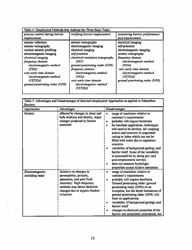
Table 4: GeophysicalMethods that Addressthe Three Basic Tasksprocess control during barrier verifiing barrier emplacement monitoring barrier performanceemplacement post emplacement
seismicrektion seismictomography electricalimagingseismictomography electromagneticimaging selfpotentialverticalseismicprofiling electricalimaging electromagneticimagingelectromagneticimaging selfpotential seismic tomographyelectrical imaging electrical resistance tomography frequency domainfrequency domain (ERq electromagnetic method
electromagnetic method groundpenetrating radar (GPR) (FW
F’ frequency domain very early time domainvery early time domain electromagnetic method electromagnetic method
electromagnetic method Pm mm(K??TW) very early time domain groundpenetrating radar (GPR)
groundpenetrating radar (GPR) electromagnetic method
mm
Table 5: Advantagesand Disadvantagesof SelectedGeophysicalApproachesas applied to SubsurfaceBarriersApproaches ~Advantages ~DisadvantagesSeismic ~affectedby changes in shear and ~ ● range of resolutionrelative to
I bulk modulusand density,major II I customer’srequirementsIchangesproducedby barrier~materials
I . probablywill requireboreholesI1° for boreholeapplication, techniques
I II
will need to be develop for couplingI
I I sourceand receiversin ungroutedI II I
casing or holes which can not beI I filled with water due to regulatoryI 1I I
concernsII
i ● variabilityof backgroundgeologyandI
I I barrier itself. Someof the variabilityI iI
is accountedfor by doing pre- andI
I I post-emplacementsurveys.iI ~● does not measurehydrologic
---- ---———— --- +--77 ———————. —-—----~__~Q@,ies exceptrelative saturation----- -—————--———-
Electromagnetic I Sensltwe to changes m [0 range of resolutionrelative toincluding radar I, permeability,porosity, I
I customer’srequirementsI saturation, and pore fluid~chemis@. High frequency
: ● probablywill requireboreholes.
I Groundpenetrating radar (groundI methods may detectdielectric i penetrating radar (GPR))is an~changesdue to organicbinders ~ exceptio%but the depth limitations ofI in b~er. II I
ground penetrating radar (GPR)willI I limit its applications.I II 1° variability ofbackgroundgeologyandI I barrier itselfI II 1’ changes in electricalpropertiesof theI I barrier not completelyunderstood,nor
15

1 ,
----- --—- ---- — 4---T:–-–----.-–--––– are the time depdent changesElectrical
E---------- -—-- --- --—.1SensWe to changesm 1- range of resolutionrelativeto~permeability,porosity, I
Icustomer’srequirements
1saturatio~ and pore fluid 1 ● probablywill requireboreholes,~chemistry. I
1° variability of backgroundgeologyandI I barrier itself~Selfpotentia.imethodsmay ~. ~hangesinel~cal propefiesof thet delineateflowpaths. II barrier not completelyundersto@ norII.—--- ---- ---- --- ---- ---- ---— ---- are the time dependentchanges
Potential Methods&---- —---- —--- -—- --—-
~heat flowtools can detectand j ● Heat flowtools will requireborehole1. heat flOW ‘ measureliquid and gas flowin ~ emplacement
! the vadosezone. I ● Longevityof tools is currentlylimitedI I
2. magneticsI Ii magneticscan detectobjects 10 rnagneticsdo not measurehydrologicI II I
propertiesor processes3. gravity I I
[ grav@ can detectdensity 10 densitychangesare small relativeto1changesdue to barrier materials. ! lateralvariations and instrumentI II I capabilitiesI I
.---— ---- -———-Other
L----------------+ ---------= ----v -------I range of resolutionrelatwe to
borehole logging I neutron logs can detectmoisture ;I customer’srequirementsinstruments I changes 10 will requireboreholes.sensors I I
I 1° must accountfor boreholeeffectsnuclear 1electrical log can detect Itracers ~conductivitychanges I
Iabsorbingsensors I I
~induction logs can detect 1I
I conductiv@r changes I
Resolution and its limitations
...Zke [barrier ver~jication] technoIo~”es shouldpermitcontinuity verljication of subsurface barriers on the order of afkw square meters in dry vadose zones to a depth of 10 meters.We seek technologies which have as small a resolution aspossible, but at least on the order of decimeter..
DOE-FY95 Needs Statement for Containment AssessmentTechnologies (ML-2)
Subsurface barriers are detectable by a variety of geophysical methods. The remainingquestion is whether the resolution of these methods meets the requirements of a siteengineer or a regulatory agency (Durant, et al., 1993). The DOE needs-statement lays outthe approximate criteria that barrier-emplacement engineers request: size on the order of a
few square meters; at a depth in the vadose zone up to IO meters; and resolution on theorder of decimeters. For a given geophysical method and an individual waste site (e.g.,conditions of soil type, saturation, electrical conductivity, and background noise), these
.
.
.
.’
16

criteria will raise basic questions: will the geophysical method finction in the soil typesand depths (issues of attenuation and background noise), and if the method can operatewith the site conditions, what are the attainable limits of detection and resolution.
There are two basic components to resolution: (1) the minimum size of a object thatcan be detected (e.g., can a single 1 mm wide fracture be detected) and (2) the precisionof locating this object in coordinate systerq e.g., L y, and z. The approach herein isheuristic by presenting some basic rules-of-thumb regarding resolution. The resolutionattainable is a fimction of several aspects: (1) the physical principles of the method, (2) theconditions of the specific site, and (3) the compromises required to field a method at aspecific site.
10 The physical principles of the methoda) Rules of i%umb for Resolution
i) Seismic (Parasnis, 1986)a) lower limit of size and location is 1/4 of the wavelength
usedii) Electromagnetic (cross-borehole; Nekut, 1994)
a) lower limit of siie and location is 1/20 of boreholeseparation
2. The conditions of the specific sitea) In general, the variation in material properties, such as seismic velocity and
electrical conductivity due to, for example, variations in saturation, hasmajor effects on resolution in terms of the technology of the imagingmethod and its instrumentation. The development of geophysicalinstrumentation, data processing and interpretation methods alone will notsignificantly increase this resolution. An understanding of the physicalprocesses, such as moisture migration and chemical evolution of porefluids, associated with barrier emplacement will improve resolution.
b) 3D spatial variation within the vadose zone; variations in moisture content,fingering, caliche
c) Variation in seismic and electrical properties laterallyd) Issues concerning the actual material properties of barriers
i) variability of material laterally with timeii) variation in electrical propertiesiii) variations in thickness of soil units and engineered units (see
figure 2)e) Background Variability
i) natural variations, facies layering, lateral and vertical variationsin density and therefore velocity, variations in saturation
ii) irregular interfaces
17

f) Man made objects in the subsurface and at the surface,
g) Stray electrical currents and electromagnetic signals
30 The compromises required to field a method at a specific sitea) Range of penetration and attenuation for example, the penetration limits of
high frequency electromagnetic methods including radar in soils of variousresistivity (see Fig. 6, this figure shows the approximate attenuation of asignal for three resistivities (50, 100, 150 ohm-m) that are representative ofarid alluvial soils over a range of frequencies representative of radarsystems. The maximum penetration or two-way travel path at 100 and 200dB attenuation ranges from 4.5 m at (60MHz, 150 ohm-m) to <1 mat (1G% 50 ohm-m)).
b) Limited range of wavelengths or frequencies, for example, seismic methodsin unconsolidated soils (Table 5 and Fig. 7, this table and figure show for arange of unconsolidated soils that possible resolution is dependent on thevelocity of the soil and the frequency transmitted in the soil and higherilequencies, e.g., 1000 ~ are required to approach resolutions of lessthan a meter.
c) Layout or geometry of the geophysical survey relative to the target (thebarrier or contaminant). Generally, the target will be better defined themore it is surrounded by sources and receivers. Hence, the higherresolution surveys will be conducted from both boreholes and the surface.Also, the resolution of survey will be limited by the obtainable length andorientation of receiver and transmitter station (see Fig. 8), e.g., in a cross-borehole survey, if the depth of borehole containing either sources orreceivers is roughly equivalent to the separation of the boreholes or the sizeof the target, then resolution will be diminished. Along similar lines, thespacing of receivers and transmitters affects the number of ray pathsthrough a given pixel of the image or the current density through a givenregion of the image. Both affect the resolution of the imaging method.
d) the difference between reflected and transmitted energy for comparingsurface to borehole methods
e) Calibration to account for three dimensional variation in geophysicalproperties and irregular interfaces(see Fig. 8, shows the effect of threedimensional structure on ray paths and current density)
f) Surface clutter and buried objects
g) Repositioning error
.
.
.
.’
18

Chemical Waste Landfiii: An example of the imitations of resolution
Demonstrations of electromagnetic and seismic methods to characterize an uniinedchromic acid disposai pit (UCAP) at the Chemicai Waste Landfill, Sandia NationalLaboratories, provide field example of the limitations of resolution (Borns, et ai. 1993).The dimensions of this pit are approximately 5 by 12 meters on the surface and 4 to 5meters deep. The soil units are stratified and channeiized unconsolidated sands and cobblezones. The resistivity of the soil units ranges from 60 to 100 ohm-w and the seismicvelocities are less than 800 m/s. The pit, therefore, is similar in scale to possible barrierand presents similar resolution requirements. For use in the demonstrations, threeboreholes were drilled to a depth of approximately 30 m. One borehole penetrated the pit,and other two boreholes straddled the pit. Separation between boreholes ranged from 4 to10 m. Both seismic and electromagnetic cross borehole surveys were tried using theseboreholes. These demonstrations at this site show that resolution attainable is a functionof the three aspects outlined in the preceding section: (1) the physicai principles of themethod, (2) the conditions of the specific site, and (3) the compromises required to field amethod at a specific site.
EXAMPLEOF ASPECT (l): THE PHYSICAL PRINCIPLESOF THE METHOD,At the chosen frequency of 15 MHz, the cross-borehole electromagnetic imaging was
abie to map the base of the disposal pit and individual soil units on the scale of 0.5 m. Thisobserved scale of resolution is consistent with the rule of thumb for electromagneticsurveys that the resolution is approximately 1/20 the of the borehole separation aspect(Nekut, 1993). For the UCAP site with a 10 m separation, the approximate resolution is[O.O5*1O]= 0.5 m.
EXAMPLEOF ASPECT (2): THE CONDITIONS OF THE SPECIFIC SITE AND ASPECT (3):THECOMPROMISES REQUIRED TO FIELD A METHOD AT A SPECIFIC SITE.
For compariso~ we conducted a cross-borehole pulsed radar survey at 60 MHz in thesame set of boreholes. The Radio Frequency Imaging Method (RIM) and the pulsed radarmethod resulted in similar images. Both images delineate four soil units in the 30 metersbelow the surface. These units are delineated probably by their varying moisture contentresulting in variations in conductivity and dielectric constant.
Theoretically, the pulsed radar unit using a higher frequency of 60 MHz versus 15 MHzshould result in higher resolution and should have the advantage of mapping variations inconductivity and dielectric constant. However, for the 50 to 100 ohm-m soils at this site,the radar method is highly attenuated even for direct ray paths over the ten meter boreholeseparation. This attenuation hits the raypath coverage, and therefore, the resolution (seeFigure 8a and 8b).
The reproducibility of these images maybe affected by lateral and vertical changes inthe physical properties with the soil unit. A primary change that can fiect the geophysicalimaging is the change in moisture content mirroring seasonal or storm infiltration. Themoisture content can also be affected by grout emplacement and aging of the grout
19

materials. Voss et al. (1994) measured a change in soil moisture from approximately 0.05g/cm3 to 0.10 g/cm3 at the grout injection intervals in a site adjacent to Chemical WasteLandfill. For electrical and electromagnetic surveys, soil moisture content, resistivity,dielectric constant, and attenuation are interrelated.
Conductivity as a function of saturation
0.018
0.(X)60.6 0.64 0.66 0.72 0.76 0.8
fractionalsaturation
Figure 6: The relationship betweensoil saturation and electricalconductivity for a typical sandy soilof the Chemical Waste Landfill(assuming 30% porosity and arange of saturation from 0.6 to0.8). A change in saturation horn0.7 to 0.6 would result in areduction in conductivity from0.013 to 0.010 S-m, which is onthe order of the observed contrastsin the electromagnetic images ofthe site.
EXAMPLEOF ASPECT (3):THE COMPROMISES REQUIREDTO FIELD A M13HOD AT ASPECIFIC SITE.
The seismic surveys were not completely tested since hurdles to implementation arose,both regulatory (limitations on the introduction of fluid into the borehole for coupling ofsource and receiver) and technical (coupling of the source and receivers with the style ofcompletion (non-grouted)of environmental boreholes). These hurdles represent afi.mdamental consideration of whether the methods can be fielded at a specific field site. Ifthe problems in fielding had been overcome, quarter wavelength resolutions of 0.1 mat1000 Hz to 4 m at 50 Hz may have been attainable. In an site adjacent to Chemical WasteLandfill, Harding (1994) was able to detect a grout injection, approximately 0.5 to 1 m incross-sectio~ at 5 m depth. While the grout injection was detected, its position in theseismic survey was displaced by a half meter from the injection point in some images. Thisapparent displacement may be some artifact of the imaging process or a three dimensionaleffect not accounted for in a two-dimensional image. For the typical unconsolidated nearsurface sites, it remains difficult to propagate a 1000 Hz or greater signal over distancesgreater than a few meters.
. .
20

Figure 7 (~ b, c): Attenuation of electromagnetic methods as a limitation of the methods
EM A ttenuation (assuming p = p.)H, -2xlo-3z~
> HY s the component of the magnetic fieldin they direction
f = @equencyz = distance along the axis that thewave is propagatingp = resistivity
150 Ohm-m attenuation
1 2 3dep h (m) ~
J 6 7
1
1E-05
1E-10
lE-15
1E-20
[5]
+1 GHz
+500 MHz
+ 100 MHz
+60 MHz
Figure. 7a: Attenuation for 150 ohm-m soil at four frequencies spanning the rangeutilized by current ground penetrating radar (GPR) systems.
21

Attenuation at 100 Ohm-m
1 2 3 ‘ep$(m) 5 6 71
1E-05
# IE-10x
1E-15
1E-20
-9-1 GHz
+500 MHz
+100 MHz
+60 MHz
Figure. 7b :Attenuation for 100 ohm-m soil at four frequencies spanning the rangeutilized by current ground penetrating radar (GPR) systems.
Attenuation at 50 Ohm-m
123$qM (~) 6 7
1
1E-05
# 1E-10x
IE-15
1E-20
+1 GHz
* 500MHz
+ 100 MHz
+60 MHz
Figure. 7C :Attenuation for 50 ohm-m soil at four frequencies spanningutilized by current ground penetrating radar (GPR) systems.
the range
.
.
.
.“
22

1 elasticvelocities (m/s) (%rasnis. 1986) Icompressional shear
medium range rangeair 330 330water 1450 1450
800 100 500XL till %L 2700 900 1300
.wavelength(m)@frequency in Hz
compressional shearfrequency 50 \ 200 : 1000 i 50 : 200 : 1000 :
.(W ~. ..... ............................r ........................... ............... .. ........ ........................... .................... ... ............................range min :max min imax min ;max min imax min imax min ~max............................. ........... ...... ........................... ............... ............ ........................... ........................ .............................medium ..................................... .......... ........................... ............... ............ ........................... ........................ ............................,air 6.6 ;6.6 1.65 11.65 0.33 io.33 o :0 0 ~o o :0................................................ ........................... ............... ............ ........................... ........................ .............................water 29 :29 7.25 ;7.25 1.45 :1.45 0 :0 0 :0 0 :0................................................ ........................... ............... ............ ................. ......... ............. ....... ............... ............sand 6 116 1.5 j4 0.3 ~0.8 2 $0 0.5 ;2.5 0.1 ~o.s...................................................................................................................................................................................glacial till 30 :54 7.5 113.51.5 ~2.7 18 ;26 4.5 ;6.5 0,9 :1.3
Table 5: Limits on Resolution; Range of Seismic Velocities and Wavelengths inUnconsolidated Sediments
Figure 8: Limits of seismic resolution for different frequencies and sediment types
23

LowASp@ct
r mxxnl. —-
.
I&hmrray-path densityaHecix xwolution
-% — / -
Figure 9a: Effects of survey aspect ratio on resolution
—
...●r
hckw~neitiu
act
I’Q--path●r rurmat&n#i&
Figure 9b: Effects of subsurface heterogeneities on resolution
.
24
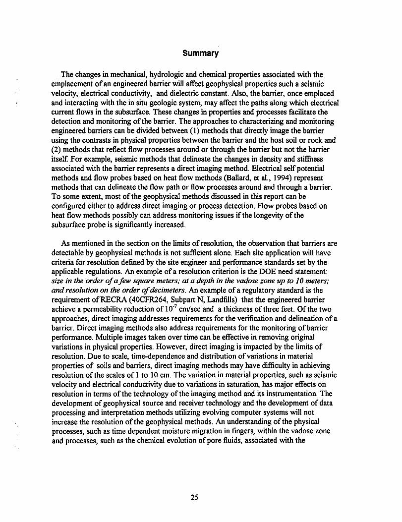
Summary
The changes in mechanical, hydrologic and chemical properties associated with theemplacement of an engineered barrier will affect geophysical properties such a seismicvelocity, electrical conductivity, and dielectric constant. Also, the barrier, once emplacedand interacting with the in situ geologic system may tiect the paths along which electricalcurrent flows in the subsurface. These changes in properties and processes facilitate thedetection and monitoring of the barrier. The approaches to characterizing and monitoringengineered barriers can be divided between (1) methods that directly image the barrierusing the contrasts in physical properties between the barrier and the host soil or rock and(2) methods that reflect flow processes around or through the barrier but not the barrieritself. For example, seismic methods that delineate the changes in density and stifiessassociated with the barrier represents a direct imaging method. Electrical self potentialmethods and flow probes based on heat flow methods (Ballard, et al., 1994) representmethods that can delineate the flow path or flow processes around and through a barrier.To some extent, most of the geophysical methods discussed in this report can beconfigured either to address direct imaging or process detection. Flow probes based onheat flow methods possibly can address monitoring issues if the longevity of thesubsurface probe is significantly increased.
As mentioned in the section on the limits of resolutio~ the observation that barriers aredetectable by geophysical methods is not sufficient alone. Each site application will havecriteria for resolution defined by the site engineer and perilormance standards set by theapplicable regulations. An example of a resolution criterion is the DOE need statement:size in the order of a finv square meters; at a depth in the vadose zone up to 10 meters;and resolution on the order of decimeters. An example of a regulatory standard is therequirement of RECRA (40CFR264, Subpart N, Landfills) that the engineered barrierachieve a permeability reduction of 10-7cm/sec and a thickness of three feet. Of the twoapproaches, direct imaging addresses requirements for the verification and delineation of abarrier. Direct imaging methods also address requirements for the monitoring of barrierperformance. Multiple images taken over time can be effective in removing originalvariations in physical properties. However, direct imaging is impacted by the limits ofresolution. Due to scale, time-dependence and distribution of variations in materialproperties of soils and barriers, direct imaging methods may have difficulty in achievingresolution of the scales of 1 to 10 cm. The variation in material properties, such as seismicvelocity and electrical conductivity due to variations in saturatio~ has major effects onresolution in terms of the technology of the imaging method and its instrumentation. Thedevelopment of geophysical source and receiver technology and the development of dataprocessing and interpretation methods utiltilng evolving computer systems will notincrease the resolution of the geophysical methods. An understanding of the physicalprocesses, such as time dependent moisture migration in fingers, within the vadose zoneand processes, such as the chemical evolution of pore fluids, associated with the
25

emplacement of a barrier need to studied. The understanding derived from these studiespermits the effects of these processes on geophysical properties to be accounted for in thefinal images.
Methods that detect flow processes and flow paths, such as electrical imaging and selfpotential arrays, offer an alternative approach. These methods can detect whether flow isoccurring around or through a barrier. Similar methods have to been used to detect flowthrough earthen dams (Hadley, 1983) and leaks in lined storage ponds (l%mgos, 1994).Such methods will not map the continuity of a barrier within the resolution requirementsof the site operating but provide a means to measure and monitor performance of abarrier. This monitoring capability can be direct towards post-closure compliance with aregulatory standard.
Recommendations
The capabilities and limitations of geophysical methods have been described in this reportand others. Table 6 addresses how the major families of geophysical methods (seismicimaging methods; electromagnetic imaging methods; and electrical imagingmethods)capture barrier processes and what the considerations or caveats for theapplication of these methods are. The application of remote sensing methods to subsurfacebarriers is a complex task due to variability of the natural subsurface and barrier and theresolution requirement of site operators and regulators. A significant hurdle toimplementation of remote sensing methods to barriers application is the incompleteunderstanding of the effects of the mechanical and chemical process that are associatedwith barrier emplacement and the effects of these processes on geophysical properties andmeasurements. Recommendations are as follows:
1. develop and utilize high-resolution three-dimensional imaging methods forelectromagnetic, seismic and electrical methods.
2. develop an understanding of the physical and chemical processes around andwithin a barriera) the three-dimensional distribution of mechanical properties around and
within the barrier, including time dependent behaviorb) chemical reactions during barrier emplacement and possible byproducts
that are introduced or producedc) chemical reactions of barrier materials with the hydrologic system or the
possible contaminantd) effects of a varying flow system in the unsaturated zone on electrical
current methods such as self potential3. pursue utilization of alternate drilling strategies such as directional and horizontal
drilling to decrease borehole effects and increase resolution4. increase longevity of flow probe technology5. develope techniques to generate higher fi-equency seismic signals with greater
range
.
26

Table 6W Seismic MethodsBarrier Processes Captured Considerations and Caveats
● emplacementof barrier materials has a distinct 1. methodsdo not direetlymonitor hydrologiceffecton seismicproptiea pmesses
● monitoring of the emplacementofbarrier 2. boreholesrequiredto reach optimum resolutionmaterial has been demonstrated(Harding, 3. boreholesneed to have appropriateaspect ratio1994) (length of boreholerelative to depth of barrier).
The possiblerange for the boreholedepth is 2xto 5X such that a barrier at 10 m depth mayrequireboreholes20 to 50 m deep.
4. horizontalor directionallydrilledboreholesandborehole-to-surfacesurveysmayenhancethe obtainableresolution.
5. resolutionmaynotmeetstateddecimetereritenz unlesshigherfrequencysourcescanbedeveloped.Still,theattenuationof thehighfrequencysignalsmayrequirecloselyspacedboreholes(i.e.,lessthan 5 m separation)
6. lateralvariationsin barrierpropertiesandnaturalvariationsin the soilmaymaskzoneswherethebarriermaybebreached(i.e.,singlefracture)
Table 6b: Electromagnetic Imaging MethodsBarrier Processes Captured Considerations and Caveats
● changes in properties related to hydrologic 1. changes in electricalpropertiesare variableproperties (porosity,saturation, permeability, within the vadosezone and around the barrier.fluid chemistry) Such changesfor a givenbarrier type are not
● reactionsbetweencontaminants and minerals completelyunderstoodin the soils may reflectedby changes in 2. methodshave not been demonstratedforelectricalproperties barrier emplacement
3. boreholesrequiredto reach optimum resolution4. boreholesneed to have appropriateaspect ratio
(length of boreholerelativeto depth of barrier).The possiblerange for the boreholedepth is 2xto 5L such that a barrier at 10m depth mayrequireboreholes20 to 50 m deep.
5. horizontalor directionallydrilled boreholesand borehole-to-surfacesurveysmay enhancethe obtainableresolution.
6. lateralvariations in barrier propertiesandnatural variations in the soil may mask zoneswhere the barrier maybe breached (i.e., single17acture)
27

Table 6c: Electrical Imaging MethodsBarrier Processes Captured Considerations and Caveats
. these methodseanmonitor processes(e.g., 1. changesin electricalpropertiesare variablefluid flow through a leak) in addition to within the vadosezone and around the barrier.changes in physicalpropertiesof the barrier Such changesfor a givenbarrier type are not
● changes in properties related to hydrologic completelyunderstoodproperties (porosity,saturation permeability, 2. boreholesrequiredto reach optimum resolutionfluid chemistry) 3. boreholesneed to haveappropriateaspeet ratio
● electricalcurrent may mimic hydrologicflow (length of boreholerelativeto depth of barrier).(i.e., self potentials may delineateflow and The possiblerange for the boreholedepth is 2x
flow rate). Electrical methodshavebeen to 5L such that a barrier at 10m depth mayaueeessfidcommerciallyin locating leaks in requireboreholes20 to 50 m deep.geomembraneliners) 4. horizontalor directionallydrilledboreholes
● reaetionsbetweeneontamirumtsand minerals and borehole-to-surfacesurveysmay enbaneein the soils may reflectedby changes in the obtainableresolution.elect.riealproperties 5. resolutionmay not meet stated deeimeter
● these methodsean be deployedin surface criteria unless higher fkqueney aoureesean bearrays thus minimizing boreholes developed.Still, the attenuationof the high
frequencysignals may require closelyspacedboreholes(i.e., less than 5 m separation)
6. lateralvariations in barrier propertiesandnatural variations in the soil may mask zoneswherethe barrier maybe breached (i.e., singlefracture)
28

REFERENCES:
Ballard, S., G. T. Barker, and R. L. Nichols, 1994, Theinsitu permeable flowsensor:Adevice for measuring groundwater flow velocity, Sandia Report, SAND93-2765,Sandia National Laboratories, Albuquerque, NM
Bartel, L. C., 1987, Results horn EM Surface Surveys to characterize the Culebra at theWIPP Site, Sandia Report, SAND87-1246
Bere~ M., Jr., and F. P. Haeni, 1991, Application of ground-penetrating radar methods inhydrogeologic studies, Ground Water, 29,375-386
Borns, D. J. , G. Newma~ L. Stolarczy~ and W. Mondt, 1993, Cross boreholeelectromagnetic imaging of chemical and mixed waste landfills, Proceedings of theSymposium on the Application of Geophysics to Engineering and EnvironmentalProblems, Environmental and Engineering Geophysical Society, 91-105, SAND92-2296C
Cale~ C., and E. Van Eeckhout, 1992, Workshop on Non invasive Geophysical SiteCharacterizatio~ EES-3 Report, Los Alamos National Laboratory, Los Alarnos,New Mexico
Dobecki, T. L., and Romig, P. R., 1985, Geotechnical and ground water geophysics,Geophysics, 50,2621-2636
Durant, N. D., V. B. Meyers, and L. A. Eccles, 1993, EPA’s approach to vadose zonemonitoring at RCRA facilities, Ground Water Monitoring and RemediatioLwinter, 151-158
Dwyer, B. P, 1994, Feasibility of permeation grouting for constructing subsurfacebarriers.in G. W. Gee and N. R. Wing, editors, In-Situ Remediation: ScientificBasis for Current and Future Technologies, Thirty-Third Hdord Symposium onHealth and the Environment, Battelle Press, Richland, WA 3-36
Elbring, G. J., 1992, Crosshole Shear-Wave Seismic Monitoring of an In Situ AirStripping Waste Remediation Process, Sandia Report, SAND91-2742, SandiaNational Laboratories, Albuquerque, NM
Flac~ D. , and U. Yaramanci, 1989, Geophysical investigations into sealing constructionand test site in rock salt: seismology, seismic tomography and geoelectrics,Proceedings of NEA/CEC Workshop on sealing of radioactive waste repositories,OCED-Paris
Fountain, L S., 1986, Detection and location of leaks in geomembrane-lined liquid wasteimpoundments using an electrical technique, Proc. Surface and Borehole Geophys.Methods and Ground Water Instrumentation Nat. Water Well Assoc., Conf andExpOS, 117-146
29

Frangos, W., 1994, Electrical detection and monitoring of leaks in lined waste disposalponds, Proceedings of the Symposium on the Application of Geophysics toEngineering and Environmental Problems, Bosto~ ~ Environmental andEngineering Geophysical Society, 1073-1082
Gale, J. E., P. A. Whherspoo~ C. R. Wilson, and A. Rouleau, 1983, Hydrologicalcharacterization of the Stripa Site, Proc. NEZ Workshop on Geological Disposalof Radioactive Waste. In Situ Experiments in Granite, OECD, 1983
Greaves, R. J., and M. N. Toksoz, 1994, Application of the multi-offset groundpenetrating radar, Proceedingsof the Symposium on the Application of Geophysicsto Engineering and Environmental Problems, Bosto~ M.& Environmental andEngineering Geophysical Society, 775-793
Hadley, L. M., 1983, A geophysical method of evaluating existing earth embankments,Bull. Assn. Eng. Geol., 20, 1361-1363
Harding, R. S. Jr., 1994, Crosswell seismic monitoring of a permeation groutingexperiment, Geotechnical Test Range-Sandia National Laboratories, Albuquerque,
Hearst, J., and P. Nelson, 1985, Well Log~”ngfor Physical Properties, McGraw-Hill, Inc.
Heiser, J. H., 1994, Subsurface barrier verification technologies, Informal Report, BNL-61127, Brookhave National Laboratory, Upton, NY
Heiser, J., L. Milan, J. Clinton, and P. Colombo, 1994, Durability of polymers forcontainment barriers, in G. W. Gee and N. R. Wing, editors, In-Situ Remediation:Scientific Basis for Current and Future Technologies, Thirty-Third HanfordSymposium on Health and the Environment, Battelle Press, Richland, WA 61-86
Johnso~ A. I., R. K. Frobel, N. J. Cavalli, and C. B. Pettersson, editors, 1984, HydraulicBarriers in Soil and Rock, ASTM Special Technical Publication 874, ASTM,Philadelphia, 332p.
King, M. S., R. W. Zimmerman, and R. F. Corwin, 1988, Seismic and electrical propertiesof unconsolidated permailost, Geophysical Prospecting 36, 349-364
Lankston, R. W., 1990, High-resolution refi-action seismic data acquisition andinterpretation, in Geotechnical and Environmental Geophysics, S. H. Ward, ed,Society of Exploration Geophysicists, OK, 45-74
Lieb, R. W., P. Zuidem~ and M. Gysel, 1989, Excavation responses in developingunderground repositories in fractured hard rock in Switzerland, in ExcavationResponse in Geological Repositories for Radioactive Waste, Proceedings of anNEA Workshop, Winnepeg, Canada, 26-28 April, 1988,91-101
Nekut, T., 1994, Electromagnetic ray-trace tomography, Geophysics, 59,371-377
Olhoeft, G. R., 1985, Low frequency electrical properties, Geophysics, 50,2492-2503
30

Olhoeft, G. R., 1986, Direct detection of hydrocarbon and organic chemicals with groundpenetrating radar and complex resistivity, Proceedings of the National Water WellAssociation Conference on Hydrocarbons and Organic Chemicals in GroundWater, 284-305
Olhoeft, G. R., 1988, Geohysics advisor expert system, Open File Report 88-399, U.S.Geological Survey, Golden, CO
Parasnis, D. S., 1986, Principles of Applied Geophysics, Chapman and Hall, LondoL 402
P.
Pelto~ J. R., L. M. Liberty, M. W. Lyle, M. E. Dougherty, D. D. Crowther, R. D. Bolger,P. J. Gallaway, and M. P. Petteys, 1994, Ground penetrating radar survey of awaste disposal area at the site of a former lumber mill, Proceedings of theSymposium on the Application of Geophysics to Engineering and EnvironmentalProblems, Bosto~ ~ Environmental and Engineering Geophysical Society, 919-927
Pfeifer, M. C., Borns, D.J., Skokan, C.K., Anderse~ H.T., and Starrett, J., 1989,Geophysical Methods to Monitor the Development of the Disturbed Rock Zonearound underground Excavations in Bedded Salt. SAND89-7055& oralpresentation and published in Proceedings of the Symposium on the Application ofGeophysics to Engineering and Environmental Problem (SAGEEP), March 13 to16, 1989, Golden, CO
Ramirez, A. L., and W. D. Daily, 1987, Electromagnetic experiment to map in situ waterin heated welded tuiT preliminary results, in Farmer, I. W., and others, editors,Rock Mechanics: Proceedings of the 28th U. S. Symposium Univ. of Arizon~TUCSOL29 June-1 July 1987, Balkeem~ Rotterdam, 37-46
Roberts, R., J. J. Daniels, and L. Peters. Jr., 1993, Accounting for near field conditionswhen interpreting 3-D ground penetrating radar (GPR) Dat~ in Proceedings of theSymposium on the Application of Geophysics to Engineering and EnvironmentalProblems (SAGEEP), Environmental and Engineering Geophysical Society, SanDiego, CA 575-
Schima, S, D. J. LaBreque, and M. Miletto, 1993, Tracking fluid flow in the unsaturatedzone using cross-borehole resistivity and IP, Proceedings of the Symposium on theApplication of Geophysics to Engineering and Environmental Problems(SAGEEP), Environmental and Engineering Geophysical Society, San Diego, CA527-541
Schneider, G. W., S. M. De Ryck, and P. A. Ferre, 1993, The application of automatedhigh resolution DC resistivity in monitoring hydrogeological field experiments,Proceedings of the Symposium on the Application of Geophysics to Engineeringand Environmental Problems (SAGEEP), Environmental and EngineeringGeophysical Society, 145-162
31

Steeples,, D. W., and R. D. Miller, 1990, Seismic reflection methods applied toengineering, environmental, and ground water problems, in Geotechnical andEnvironmental Geophysics, Vol. 1, Review and Tutorial, S. H. Ward, cd., Societyof Exploration Geophysicists, Tulsa, OK 1-30
Stolarczy~ L. G., 1987, Determining coal seam roof rock fracture zones withelectromagnetic (EM) wave tomography, in Farmer, I. W., and others, editors,Rock Mechanics: Proceedings of the 28th U. S. Symposium Univ. of Arizon~Tucso~ 29 June-1 July 1987, BaIkeem~ Rotterdaq 29-36
TeMord,W. M., L. P. Geldart, R. E. Sheriff, and D. A. Keys, 1978, Applied Geophysics,Cambridge University Press, Cambridge, 86op
Truskowski, M. G., and H. T. Anderse~ 1993, Resistivity changes over time related tomodeled fluid flow in Room-Q of the Waste Isolation Pilot Plant, Proceedings ofthe Symposium on the Application of Geophysics to Engineering andEnvironmental Problems (SAGEEP), Environmental and Engineering GeophysicalSociety, 545-558
Voss, C. F., C. M. Einberger, and R. V. Matalucci, 1994, Evaluation of two grouts forconstructing subsurface barriers, in G. W. Gee and N. R. Wing, editors, In-SituRemediation: Scientific Basis for Current and Future Technologies, Thirty-ThirdHanford Symposium on Health and the Environment, Battelle Press, Richland,w& 113-134
Ward, S. H., editor, 1990, Geotechnical and Environmental Geophysics: Volume 1:Review and Tutorial; Volume II: Environmental and Groundwate~ and VolumeIII: Geotechnical, Investigations in Geophysics No.5, Society of ExplorationGeophysicists, TUISXOK
White, P. A., Measurement of groundwater parameters using salt-water injection andsurface resistivity: Groundwater, 26, 179-186
32

DISTRIBUTION LIST
DOE OffIces
1 US Department of EnergyAlbuquerque Operations OfficeAttn: National Atomic MuseumLibraryP.O. Box 5400Albuquerque, NM 87185-4300
1 US Department of EnergyResearch & Waste Management
DivisionAttn: DirectorP.O. Box EOak Ridge, TN 37831
1 US Department of EnergyAlbuquerque Operations OfficeETNATTN: Dennis OlonaPennsylvania/H StreetAlbuquerque, NM 87116
1 US Department of EnergyAlbuquerque Operations OtliceETNATTN: Dan KrivitzkyPennsylvania/H StreetAlbuquerque, NM 87116
1 US Department of EnergyAlbuquerque Operations OfficeERPOATTN: Julianne LevingsPennsylvania/H StreetAlbuquerque, NM 87116
1 US Department of EnergyOffice of EnvironmentalRestorationand Waste ManagementAttn: J. Lytle, EM-30Forrestal BuildingWashington, DC 20585-0002
1 US Department of EnergyOffice of EnvironmentalRestoration and WasteManagementAttn: M. Frei, EM-34,
Trevion IIWashington, DC 20585-0002
1 US Department of EnergyOffice of EnvironmentalRestoration and WasteManagementAttn: S. Schneider, EM-342,
Trevion IIWashington, DC 20585-0002
1 US Department of EnergyOffice of Technology DevelopmentAttn: S. Chamberlain, EM-551,
Trevion II19901 Germantown Rd.Germantown, MD 20874-1290
Dist-1
State Agencies
1, NM Energy, Minerals, and NaturalResources DepartmentAttn: Library2040 S. PachecoSanta Fe, NM 87505
1 NM Environment DepartmentSecretary of the Environment1190 St. Francis DriveSanta Fe, NM 87503-0968
1 NM Bureau of Mines and MineralResources
SOCOITO,NM 87801
Other DOE Labs
1 Brookhaven National Laborato~Attn: J. HeiserDepartment of AdvancedTechnologyP.O. Box 5000Upton, NY 11973-5000
Libraries
1 Thomas Brannigan Libra~Attn: D. Dresp106 W. Hadley St.Las Cruces, NM 88001
1 Government PublicationsDepartmentZimmerman LibraryUniversity of New MexicoAlbuquerque, NM 87131
1 New Mexico Junior CollegePennell LibraryAttn: R. HillLovington HighwayHobbs, NM 88240
1 New Mexico State Libra~Attn: N. McCallan ,.325 Don Gaspar hSanta Fe, NM 87503
1 New Mexico TechMartin Speere Memorial LibraryCampus StreetSOCOflO,NM 87810
Internal
1 MS 072410 MS 075012 MS 07501 MS 07261 MS 07151 MS 07561 MS 071915 MS 0719
D. L. Hartley, 6000D. J. Borns, 6116Staff, 6116J. K. Rice, 6600R. Luna, 6603G. Allen, 6607J. E. Nelson, 6621Staff, 6621
Required Distribution:
5 MS 0899 Technical Library, 134141 MS 0619 Print Media, 134162 MS 0100 Document Processing for
DOE/OSTI1 MS 9018 Central Technical Files,
8523-2
‘1
Dist-2