geometrical and dimensional measurement planning -a ...446055/fulltext01.pdf · geometrical and...
TRANSCRIPT

Geometrical and dimensional Measurement Planning -a systematic and holistic approach
Richard Lindqvist
Licentiate Thesis
School of Industrial Engineering and Management Department of Production Engineering
The Royal Institute of Technology, Stockholm October 2011


TRITA IIP 11-02 ISSN 1650-1888 ISBN 978-91-7415-958-5 Copyright © Richard Lindqvist School of Industrial Engineering and Management Department of Production Engineering Metrology and Optics The Royal Institute of Technology S-100 44 Stockholm

I
SAMMANFATTNING För att försäkra sig om den slutliga kvaliteten på maskinbearbetade komponenter måste tillverkande företag mäta och verifiera de geometriska och dimensionella egenskaperna på komponenter innan dem skickas vidare nedströms till den mer värdeskapande monteringen. Det är idag vanligt att den geometriska och dimensionella mätningen och verifieringen uppstår varje gång då en maskin ställs om, när man startar om eller startar upp en ny produktionslina eller då en produktionsprocess ändras. Produktionsteknisk mätteknik och resultat från utförda mätningar används sedan som indata för statistisk processtyrning och övervakning av produktionsprocesser. Syftet med vår forskning har varit att först ta fram en nulägesbild av mätteknisk beredning inom fordons- och flygindustrin och utifrån den identifiera framtida trender med behovsanalys och gap. Utifrån analysen har vi sedan utforskat och utvecklat en modell och metodik för mätteknisk mät- och styrbarhetsberedning. I denna licentiat avhandling har vi utforskat området geometrisk och dimensionell mät- och styrbarhetsberedning (GMCP - Geometrical and dimensional Measurement and Controllability Planning). Vi presenterar en nulägesanalys av området och vi presenterar en teori med modell och ramverk för GMCP. Vidare har vi utforskat en metodik och verktyg benämnd kvalitetssäkringsmatris (QAM - Quality Assurance Matrix) och som vi lyfter fram i denna avhandling. I slutet av avhandlingen presenteras och diskuteras dem hittills uppnådda resultaten från forskningen och i det sista kapitlet dras slutsatser och den fortsatta forskningen inom ”SIMET-GICP” projektet presenteras.

II

III
SUMMARY In order to ensure final product quality on machined components, manufacturing enterprises must measure and inspect the geometrical and dimensional characteristics of components before they go into higher-value assemblies. Commonly, the geometrical and dimensional measurement and inspection occurs every time at machine tool set-up, when a line is restarted or if the production process is changed. Production metrology and results from production measurements is used as input data for statistical process control and monitoring of production processes. The purpose of our research has been to firstly perform a state of the art analysis in the area of measurement planning applied in the automotive and aerospace industry. The output from the state of the art study has then been used to identify future trends and needs including a gap analysis. Then we used the analysis to explore and develop a model and methodology for measurement and controllability planning. In this licentiate thesis we have explored the area of GMCP (Geometrical and dimensional Measurement and Controllability Planning). As a major result in this thesis a state of the art survey on GMCP is presented. Based on the state of the art study a theory and model framework for GMCP has been explored and a methodology and tool called QAM (Quality Assurance Matrix) is highlighted in this thesis. In the end of the thesis we present and discuss the present research results we have accomplished and in the final chapter we draw conclusions and outline the continued research within the SIMET-GICP project.
KEYWORDS Geometrical, dimensional, measurement planning, controllability, GMCP, quality assurance matrix and methodology, QAM, critical key characteristic.

IV
LIST OF FIGURES Fig. 1. Complex products from Saab AB, Scania CV and Volvo CE. 1 Fig. 2. An old artistic illustration of a typical product realization 3 process flow from an idea to final product. Fig. 3. Product development workshop at Volvo CE in Eskilstuna. 4 Fig. 4. A 3D-model based design definition, visualized in a CAD 5 system. Fig. 5. Consortium constellation within the SIMET research forum. 8 Fig. 6. Product realization steps and prioritized research areas 13 within the SIMET forum. Fig. 7. Comparision and presentation of different research methods. 16 Fig. 8. Roadmap to new knowledge and methodology for 17 measurement planning. Fig. 9. Delimitations in the SIMET research project, restricted to 18 geometrical and dimensional production metrology. Fig. 10. The meter prototype made of a Platinum Iridium alloy 23 composition. Fig. 11. The Saab Aerostructures business model. 26 Fig. 12. The Volvo CE Global Development Process (GDP). 27 Fig. 13. The current identified Metrology Interoperability Standards 28 landscape in the year of 2006. Fig. 14. An representation of a A0 IDEF0 model intended for; 30 “High-level measurement process planning (HIPP)”. Fig. 15. An representation of a A1-A5 IDEF0 model intended for; 30 “High-level measurement process planning (HIPP)”. Fig. 16. A representation of the eQuiPP consortium developed 31 interoperability situation. Fig. 17. Boeing AQS process flow according to the D1-9000-1 37 requirement document. Fig. l8. A general verification process. 39 Fig. 19. Scania CV quality assurance process, current state. 44 Fig. 20. Scania CV quality assurance process, proposed future state. 44 Fig. 21. The main activities in product development, industrialization 50 and reuse of design and production knowledge. Fig. 22. The scope and process for information management. 52 Fig. 23. Screen capture of a web-based guide, the example show the 53 work instruction web-based guide. Fig. 24. The basic principle of ASTRAKAN modeling. 54

V
Fig. 25. A holistic model approach where Inspection and 55 Measurement Planning is one important and key enabling functional competence. Fig. 26. The condensed version of the high-level GMCP information 56 model. Fig. 27. Example of Scania CV´s COR system. 59 Fig. 28. Functional breakdown and interrelationships. 60

VI
LIST OF PUBLICATIONS Paper A Lindqvist, R., Lundgren, M., Hedman, S., Lindahl, P., Vångell, T., and Mattsson, L. “An information model approach for systematic and holistic Geometrical Inspection and Control Planning (GICP)” Peer reviewed and published in the Journal of the CMSC. Presented at the 25: th annual CMSC conference, Louisville, Kentucky, USA, 2009. Vol. 4, No. 2, pp 20-26. Paper B Lindqvist, R., Horst, J., Brown, R., and Mattsson, L. “EQUIPP - Exchange of Quality measurement Process Plans “ Peer reviewed paper, published in the conference proceedings and presented at the 10: th International Symposium on Measurement and Quality Control (ISMQC) in Osaka, Japan, September 2010. pp D3-142-1 to D3-142-4. Paper C Lindqvist, R., Karlsson, K-J., Hedman, S., and Mattsson, L. “Geometry Assurance and Quality Control Planning by QAM” Peer reviewed paper, published in the conference proceedings and presented at the 10: th International Symposium on Measurement and Quality Control (ISMQC) in Osaka, Japan, September 2010. pp D3-144-1 to D3-144-4.

VII
"Everybody Needs to Deviate from the Norm..." Michael A. Lazar
Boeing 787 Dreamliner Technical Specialist Computer Aided Metrology Systems (CAMS)
Preface and Acknowledgement Performing research in production engineering and in the area of production engineering metrology is exciting and challenging. Without production engineering measurements there is no knowledge and no facts to make important production and manufacturing decisions on. Today production engineering metrology is being more generally regarded as a prerequisite in modern manufacturing of complex parts and components and companies are realizing the true value of implementing modern state of the art production engineering metrology solutions within their advanced production systems. After more than 10 years working for the aerospace company Saab AB in Linköping I decided to move on into higher education research. However the door into the world of research was opened for me by Ph.D Sven Hjelm at Scania CV who initiated me on an open position at KTH and in a research project called SIMET (Swedish Industrial Metrology forum). For this I am very gratefully thankful to Sven for guiding me into world of production engineering research at KTH. Though my research project assignment and my research work is very important I have now realized that working as a Ph.D student is mostly about education, continuously learning, critical thinking and reflecting on my own and other researchers work. This licentiate thesis and all the work to produce it couldn´t have been realized without the guidance, collaboration and help from many colleagues and friends. Firstly I would like to thank Vinnova, Scania CV, Volvo CE, Saab AB, Hexagon Metrology Nordic, Scandinavian Mitutoyo and Renishaw AB and the MERA research program for financially supporting my research. I would like to thank all my colleagues and friends at KTH Production Engineering and especially my mentor and academic supervisor professor Lars Mattsson for introducing me to the very interesting and broad world of production engineering metrology and for his active guidance of my research work. A special appreciation goes to my industry mentor, the quality and production engineering metrology guru and expert at Volvo CE in Eskilstuna, Mr. Karl-Johan Karlsson. Last but not least I give all my thoughts and appreciation to my family and to my wife Elin and to our amazing daughter Ingrid. Thank you for your patience, care and understanding for what I am doing in my professional life.

VIII
Abbreviations AIMS/PE – Advanced Integrated Mathematical System / Parametric Evaluator. It is a computer aided measurement and inspection planning system. Developed by McDonnell Douglas (today The Boeing Company) starting in 1975. CAD – Computer Aided Design CAE – Computer Aided Engineering CAM – Computer Aided Manufacturing CAPP – Computer Aided Process Planning CAIP – Computer Aided Inspection Planning CAQ – Computer Aided Quality control DFM – Design For Manufacturing DP – Design Parameter DMIS - Dimensional Measurement Interface Standard. Developed and managed by the DMSC (Dimensional Metrology Standards Consortium) DMSC - Dimensional Metrology Standards Consortium FAI - First Article Inspection (EN/SS 9102 First Article Inspection) FR – Functional Requirement GMCP - Geometrical and dimensional Measurement and Controllability Planning GPS - Geometrical Product Specifications, (ISO/TC 213 Geometrical Product Specifications and Verifications, ISO 1101:2004, SIS handbook 545:2007, utgåva 2) IDEF0 – Integration DEFinition language 0 IDEF3 – Integration DEFinition language 3 ISO – International Organization for Standardization KC - Key characteristic Manufacturing/Production – The terms is treated equally in this thesis; however the focus is on component manufacturing/production PMI - Product Manufacturing Information QFD - Quality Functional Deployment QAM - Quality Assurance Matrix and methodology (QAM) SPC - Statistical Process Control STEP - STandard for the Exchange of Product model data XML – eXtensible Mark-up Language XSD - eXtensible Schema Definition

IX
Contents SAMMANFATTNING ............................................................................................ I
SUMMARY ............................................................................................................. III
KEYWORDS ........................................................................................................... III
LIST OF FIGURES ................................................................................................. IV
LIST OF PUBLICATIONS ................................................................................... VI
ABBREVIATIONS .............................................................................................. VIII
1 INTRODUCTION ........................................................................................... 1
1.1 PRODUCTION ENGINEERING METROLOGY IN A PRODUCT REALIZATION AND
MANUFACTURING CONTEXT ..................................................................................... 1 1.2 SUMMARY AND CONCLUDING REMARKS ON CHAPTER 1 .............................. 6
2 BACKGROUND .............................................................................................. 7
2.1 BACKGROUND TO THE RESEARCH PROJECT ................................................. 7 2.2 INDUSTRY TARGETS .................................................................................... 9 2.3 COPQ - COST OF POOR QUALITY .............................................................. 10 2.4 RESEARCH OBJECTIVES ............................................................................. 11 2.5 PROBLEM STATEMENT AND WORKING HYPOTHESIS ................................... 11 2.6 DISCLAIMER .............................................................................................. 12 2.7 SUMMARY AND CONCLUDING REMARKS ON CHAPTER 2 ............................ 12
3 RESEARCH APPROACH ............................................................................ 13
3.1 PRIORITIZED SIMET RESEARCH ................................................................ 13 3.2 RESEARCH METHODOLOGY ....................................................................... 14
3.2.1 The research process and identified activities ..................................... 14 3.2.2 The experiential researcher ................................................................. 15
3.3 RESEARCH QUESTIONS AND GAP ANALYSIS ............................................... 16 3.3.1 Research questions ............................................................................... 16 3.3.2 Gap analysis and roadmap .................................................................. 17
3.4 RESEARCH DELIMITATIONS ....................................................................... 18 3.5 CONTRIBUTION OF THE THESIS AND APPENDED PAPERS ............................. 19 3.6 DISPOSITION OF THE THESIS ...................................................................... 20 3.7 SUMMARY AND CONCLUDING REMARKS ON CHAPTER 3 ............................ 21
4 STATE OF THE ART IN GMCP ................................................................ 23
4.1 HISTORICAL VIEWPOINT ON PRODUCTION METROLOGY AND DIMENSIONAL
MEASUREMENT ....................................................................................................... 23

X
4.2 NEW EMERGING PRODUCTION METROLOGY ............................................... 24 4.3 INTRODUCTION TO THE FIELD OF GMCP ................................................... 24
4.3.1 The product realization perspective ..................................................... 24 4.3.2 Information and activity modeling on GMCP? ........................................ 27
4.4 ACADEMIC AND INDUSTRY CONTRIBUTIONS .............................................. 32 4.4.1 ASME standard B89.7.2-1999 - dimensional inspection planning ....... 32 4.4.2 The GPS handbook, SIS 545:2007 ....................................................... 32 4.4.3 The handbook on CMM metrology, SIS 543:2008 ............................... 33 4.4.4 Technical specification ISO/TS 16949 ................................................. 33 4.4.5 SS-EN 9102 FAI and SS-EN 9103 VMKC ............................................ 35 4.4.6 VRM – Variation Risk Management ..................................................... 38 4.4.7 MPV – Module Property Verification .................................................. 38 4.4.8 CAIP (Computer Aided Inspection Planning) systems ......................... 39 4.4.9 Software and file formats ..................................................................... 40 4.4.10 Commercial proprietary GMCP software ....................................... 40
4.5 GMCP APPLIED IN SWEDISH AUTOMOTIVE AND AEROSPACE INDUSTRY .... 43 4.5.1 Scania CV (Automotive) ....................................................................... 43 4.5.2 Volvo Construction Equipment (Automotive) ....................................... 45 4.5.3 Saab AB – Saab Aerostructures (Aerospace) ....................................... 47
4.6 SUMMARY AND CONCLUDING REMARKS ON CHAPTER 4 ............................ 48
5 THEORY AND MODEL FRAMEWORK FOR GMCP ........................... 49
5.1 PRODUCTION METROLOGY IN COMPONENT MANUFACTURING ................... 49 5.2 INFORMATION MODELLING APPROACH ...................................................... 51
5.2.1 Information and activity modeling ....................................................... 51 5.2.2 Measurement process planning and model driven process planning ... 52 5.2.3 Activity modeling methodology ............................................................ 53 5.2.4 GMCP information model and relation to QAM? ................................ 54
5.3 DEVELOPMENT OF A DETAILED QAM METHODOLOGY .............................. 56 5.3.1 What questions should always be asked in measurement planning? .... 57 5.3.2 Understanding critical and non critical requirements ......................... 58
5.4 DESCRIPTION OF THE QAM TOOL AND METHODOLOGY ............................ 60 5.5 GENERAL PRINCIPLES AND RULES IN GMCP ............................................. 62 5.6 SUMMARY AND CONCLUDING REMARKS ON CHAPTER 5 ............................ 63
6 RESULTS AND DISCUSSION .................................................................. 65
6.1 THE QAM TOOL AND METHODOLOGY ....................................................... 65 6.2 THE EQUIPP STANDARDIZATION PROJECT ................................................. 66
6.2.1 Results .................................................................................................. 66 6.2.2 Discussion ............................................................................................ 66
6.3 SUMMARY AND CONCLUDING REMARKS ON CHAPTER 6 ............................ 67

XI
7 CONCLUSIONS AND FUTURE WORK ................................................. 69
7.1 THE AUTOMOTIVE AND AEROSPACE INDUSTRY CHALLENGES .................... 69 7.2 PRODUCTIVE PRODUCTION METROLOGY ................................................... 69 7.3 THE GMCP INFORMATION MODEL AND QAM METHODOLOGY ................. 70 7.4 THE INTERNATIONAL QIF STANDARDIZATION PROJECT ............................ 70 7.1 SUMMARY AND CONCLUDING REMARKS ON CHAPTER 7 ........................ 71
REFERENCES ......................................................................................................... 73
APPENDED PAPERS
PAPER A PAPER B PAPER C

XII

1
1 Introduction "If you can’t measure it, you can’t understand it. If you can’t understand it, you can’t control it. If you can’t control it, you can’t improve it."
James Harrington 1.1 Production engineering metrology in a product
realization and manufacturing context Metrology – to be distinguished from weather forecasting meteorology – is the science of measurement. This thesis is focusing on Geometrical and dimensional Measurement and Controllability Planning from now on abbreviated GMCP. The research in this rather unexplored area is limited to the automotive and aerospace industry and the main interaction has been with manufacturing companies such as Scania CV and Volvo CE and the aerospace company Saab AB. In Fig. 1 we can see some representative complex products these companies have developed or currently are under development.
Fig. 1. Complex products from Saab AB, Scania CV and Volvo CE. By the courtesy of Saab AB, Scania CV and Volvo CE.

2
A commonality among these different products is that their mechanical structure are mainly built up by many different components that are being assembled together to create a vehicle structure, i.e. airframe, chassis etc. However, firstly and in order to fit to each other and fulfill the component requirements these components need to be manufactured to the tolerances stated by the design engineer, production and process engineer and production metrology engineer. In this research we have studied specifically what, how, by whom, when, where in the machining process of components, such like 5-axis CNC (Computer Numerical Controlled) machining, one should perform production engineering measurements, i.e. the planning and preparation of measurements. However the future intent is to generalize the research results and apply it into other specific detail manufacturing areas, i.e. sheet metal, carbon fiber composites and other specific manufacturing disciplines. Today, global development and product realization projects are typically performed according to well defined project models and specified working processes. More of these models will later on be described in the state of the art chapter. However in order to explain these working processes from a product idea to final assembled, validated, verified and tested product we would like to use the following simplified, though illustrative picture, see Fig. 2. In Fig. 2 we can observe that there are many different activities being performed sequentially, in parallel or as iterative procedures, though it somehow follows a logical sequence of activities which creates the main working process. In this old flowchart we can observe that measurement and inspection is being performed in the end of the product realization process and prior to delivery of the product. That has been the traditional way in many companies and has created lots of hassle, as it is not until the last stage it is discovered that a design and its related geometrical and dimensional tolerance requirements cannot be verified, and comply with specifications and hence it also might be too late to make verifications because the inspection and verifications are performed to late and not frequent enough in previous stages of

3
operations in the production process which has generated errors and caused defects.
Fig. 2. An old artistic illustration of a typical product realization process flow from an idea to final product. By the courtesy of Saab AB. The new approach to solve these kinds of problems is presented as a structured and holistic model and methodology and one key issue is the early involvement of metrology experience already at the design and manufacturing planning and preparation stage. To exemplify the new way of working we refer to Fig. 3 which illustrates a typical dialogue that could take place in a GMCP enrolled company. At a minimum, the four roles shown in Fig. 3 are going to meet each other in a product development project meeting.

4
Fig. 3. Product development workshop at Volvo CE in Eskilstuna. By the courtesy of Volvo CE. They are currently in a design phase called detailed design. This means that the functional requirements and related GD&T (Geometrical and Dimensional Tolerance) requirements has been more or less decided and “frozen” by the design engineer. The team will in this case study a component that is going to be manufactured by machining operations and in a typical production process flow comprising of the following activities and operations; forged raw material from supplier, 5-axis multipurpose CNC machining, cleaning and visual inspection. First the team needs to look at the proposed detail design that the design engineer has developed and discuss the requirements from design engineering, production engineering, and quality engineering and production metrology engineering point of view. In Fig. 4 we can see the proposed detail design intent. It is a virtual 3D (Three Dimensional) model based design definition which means that the team can see all applicable and proposed geometrical and dimensional requirements, applicable tolerances and surface structure requirements annotated on the component, visualized in the CAD (computer aided design) system.

5
Fig. 4. A 3D-model based design definition, visualized in a CAD system. By the courtesy of Saab AB. The designer gives the background requirements on the component, the required functionality, interface and fittings to other components and how he or she has realized that by proper material choices, working with standard design elements, dimensioning, tolerances and datum reference systems, all presented and visualized in his or hers 3D CAD model. After this outlook, the CAD model with associated features and datum reference system is scrutinized from a manufacturing, verification and quality perspective by the specialists in these fields. Can this component be produced with existing machine tools? If not we must consider an alternative design or request investments of new machine tools. Next, the metrology issues are thoroughly investigated with regard to what, how, when, where and by whom the component tolerances be checked. Can we select a few critical measures (i.e. measurand according to ISO/TC 213) to keep track of the manufacturing process? Do we have calibrated dimensional measurement equipment in order to make reliable production

6
engineering measurements during production? What kind of environment and state on the component should be fulfilled before a production metrology measurement can be carried out? How frequently and how many components should be measured each time?
1.2 Summary and concluding remarks on chapter 1 We can now understand and realize that there are many engineering problems and questions to be discussed and solved in a component project development meeting like the one described above. It is therefore important to work close together and collaborate in so called IPD (Integrated Product Development) teams and work concurrently together with each other with a common goal to achieve a highly capable and quality assured component with zero defects during manufacturing, and from the very first produced unit. It is also important to have and use well proven principles, methods, tools, guides and standards (international, national and company standards) to follow when the engineers do the final detail design engineering work. This is where this thesis plays a role, by investigating current standards and development in measurement and inspection planning and concluding them with empirical knowledge from the companies to propose a new holistic and systematic model for the entire geometrical and dimensional measurement and controllability planning process.
7
2 Background “Competence in measurement is essential for humans to function effectively in modern civilization”.
L. Finkelstein
2.1 Background to the research project The increasing environmental demands to reduce emissions and fuel consumption have put a pressure on the automotive and aerospace industry to search for new materials and more effective and sustainable design and production solutions. One key factor is the use and development of effective production engineering and productive industrial production engineering metrology, from now on only expressed as production metrology. There are few activities in the manufacturing process of complex components and products that are as highly crucial for the final product quality functioning as geometrical and dimensional production metrology. Despite this fact, production metrology has for a long time been neglected at many managing boards, and the building of competence in this field has not been in focus compared to overall quality control systems such as SS-EN ISO 9000 and 9001. Most likely this biased vision of metrology is based on the myth that industrial production metrology is only related to extra costs and non-value adding activities. This negative attitude to production metrology has been reported, discussed and argued against in (Kenger, 2006; Kunzman, 2005 and Shingo, 1986). Our opinion and many other experienced researchers and industry representatives opinion is that industrial production metrology is a prerequisite (Kunzman, 2005; Weckenmann, 2008) in modern manufacturing of complex components, assemblies and final assembled products. The established SIMET (Swedish Industrial Metrology Forum) project is currently performing research in the area of GMCP. This research area has been prioritized and selected by the board of the SIMET forum. SIMET is a neutral, national forum for industrial geometrical and dimensional metrology people to interact and create a renewed

8
interest in the area of industrial geometrical and dimensional metrology, (Verkstadstidningen, 2009). SIMET will develop the necessary educational tools to improve education and raise the competence of individuals so they are prepared for the upcoming challenges of future industrial metrology. The forum is managed by a board and the companies, institutes and academic partner in the forum is according to Fig. 5:
Fig. 5. Consortium constellation within the SIMET research forum. What we have seen so far is that effective and direct feedbacks of captured geometrical and dimensional data information from the manufacturing process and the combination of continuous improvements are the key components to gain competitiveness over time. The goal with the geometrical and dimensional measurements is to gather correct geometrical and dimensional data in order to analyze, control and achieve predictability and stable condition of the manufacturing processes. This will also form the base for further improvements. With more effective information and activity models and methodology tools for geometrical, dimensional inspection and

9
control planning, more efforts can be put into the direct value adding activities within manufacturing and assembly operations. Current three dimensional (3D) model based definition and planning research in the area of information systems and information technology is the driving force for future effective and productive GMCP. The identified interoperability problems between hardware and software system platforms need to be solved. This work is mainly promoted by the National Institute of Standards and Technology (NIST) and the Dimensional Measuring System Consortium (DMSC) in the USA working under the project name eQuiPP (exchange of Quality measuring Process Plans), (eQuiPP, 2009), nowadays called QIF (Quality Information Framework). Our research at the department of production engineering at KTH has led to results that enable us to take an active role in the eQuiPP project group.
2.2 Industry targets The industrial targets of the SIMET GMCP project are to minimize the CoPQ (Cost of Poor Quality) and the related environmental impact by introducing a holistic and systematic approach to GMCP. The Swedish automotive industry with companies like Scania CV and Volvo CE are claiming a responsibility to provide society with transport solutions that will reduce the negative environmental impact and contribute to social development. The Volvo Group sustainability report from 2008, (Volvo Group, 2008), states: “The Volvo Group has 60 production plants in 19 countries worldwide. All production sites must meet minimum environmental requirements and pursue improvement programs. Requirements include that energy consumption, waste volumes and emissions to air are to be monitored, along with specifications of maximum emissions to air and water.” (Volvo Group, 2008) In the international aerospace industry and for transportation in the air even more challenging goals have been set up by the CleanSky project (Cleansky, 2009). According to the “Advisory Concil for Aeronautics Research in Europe – the European Technology Platform for

10
Aeronautics and Air Transport” the following goals have to be reached in 2020 (Cleansky, 2009):
50% reduction of CO2 emissions through drastic reduction of fuel consumption.
80% reduction of NOx (nitrogen oxide) emissions. 50% reduction of external noise. A green product life cycle: design, manufacturing,
maintenance, disposal and recycling.
2.3 CoPQ - Cost of Poor Quality Previous research has shown that the CoPQ (Cost of Poor Quality) is a major waste factor in production, where it contributes 10 to 40% of an operations total cost turnover (Kenger, 2006; Höglund and Sörqvist, 2007; Özaksel, 2008). These research results are in close agreement with the 15-35% estimated by Swedish production engineers’ active in the SIMET forum. In the aerospace industry equal amounts of potentials has been identified. The following quote is taken from Aerospace Engineering and Manufacturing online, (AEM, 2008), and is a representative example on the current potential to cut the CoPQ in the aerospace industry; “The payoffs can be significant. Over three years, Goodrich Corp. cut its quality escapes by 70% while trimming the costs of poor quality such as scrap, rework, and warranty costs by 40%.” "That saves our customers and ourselves over $100 million every year," said Steve Wells, Vice President of Quality and Continuous Improvement, Goodrich. "Quality can be a source of improvement for operating margins." Not to forget the problems Toyota were facing with their product quality. The latest estimation was that CoPQ to handle the acute quality problems on delivered cars and to get them adjusted will cost Toyota approximately $900 million, (NyTeknik, 2009; Topnews, 2009). Globally, Toyota needs to recall over 4,5 million vehicles. Bad- will related to lost sales is estimated to cost Toyota $155 million weekly. It seems obvious that Swedish manufacturing companies would benefit from a more fundamental investigation aiming to identify the visible and hidden costs of poor quality. Thus, a method to perform

11
correct and systematic measurements on strategic important geometrical and dimensional features on a component, module or product (Lindqvist et. al., 2009; Lindqvist and Vångell. 2008; Kenger, 2006) could be one of the most profitable contributions in a production line. The CoPQ can be directly transferred to environmental impact and long term sustainability for a manufacturing company. The CoPQ is most likely directly proportional to the environmental impact, but this needs to be further investigated. Many companies have attempted to develop cost models to calculate the CoPQ, but these models need further refinement and research to include the impact on environment and sustainability targets.
2.4 Research objectives The research objectives of this licentiate work are to investigate and develop principles and methodology to form a base and framework for a holistic and systematic GMCP approach. This includes the development of an activity model and a Quality Assurance Matrix (QAM) and methodology.
2.5 Problem statement and working hypothesis The problem statement in this work includes: We lack knowledge and a comprehensive overview and state of the art study on what has been done in the context of GMCP. Industry and academy lack profound gathered knowledge in the field of GMCP. Industry and academy needs a developed methodology and a structured and holistic approach to GMCP and the current lack of this is anticipated to be very costly for a product developing and manufacturing company. From reviewing reports, searching for papers, interviewing people and searching the internet for GMCP processes and knowledge used in the automotive and aerospace industry the conclusion is that there is a great variety in the implementation of GMCP activity models, processes and methodologies. They tend to be different from supplier to supplier, from company to company and between different

12
industries, (Lindqvist et. al., 2009). Despite being a highly important field, surprisingly little academic research has been published on systematic and holistic models for GMCP. Many papers refer to specific systematic inspection planning using coordinate measuring machines (CMM:s), for example (Zhaoa et. al., 2009; Cho et. al., 2007; Helgoson, 1998; Kim and Chang, 1996). However, very few journal publications are presenting systematic and holistic views regarding model based and model driven development and planning of complex components that is going to be manufactured, verified and controlled by measurements, (Lindqvist et. al, 2009; Lindqvist and Vångell, 2008; Sivard et. al., 2008). The conclusion and working hypothesis is: There is a gap to fill in the development and use of a holistic, systematic and in the long term, interoperable and standardized GMCP activity model and methodology!
2.6 Disclaimer The name and vendors products are used in this licentiate thesis solely for descriptive purposes only. This does not imply any endorsement or recommendation of any vendors’ products by the author.
2.7 Summary and concluding remarks on chapter 2 In this chapter we have accounted for the research and scientific approach. We have highlighted the background to the problem and discussed why we have chosen GMCP as a prioritized research area and we have put forward the industry targets and future goals. In the end of the chapter we present the research objectives including the problem statement and the current working hypothesis.

13
3 Research approach “You should not ask questions without knowledge.” W. Edwards Deming
3.1 Prioritized SIMET research The background and initiation of the research presented in this licentiate thesis is a research project identified by the Swedish Industrial Metrology (SIMET) forum, (SIMET, 2009). The SIMET forum has addressed and put priority on four main research areas, marked numbers 3-6 in Fig. 6. The research area with highest priority, and selected by the board of the SIMET management committee, was; Geometrical and dimensional Inspection and Control Planning. As inspection is more associated with defect detection we decided to broaden the scope to geometrical and dimensional measurement and controllability planning and consequently adopt the abbreviation GMCP for this important procedure in the overall quality management and quality control system.
Fig. 6. Product realization steps and prioritized research areas within the SIMET forum.

14
3.2 Research methodology
3.2.1 The research process and identified activities Sohlenius (2004) has developed and described a scientific method for research and development in the area of science of engineering. The method comprises of six steps and those are:
The research presented in this licentiate thesis has been planned and executed with this method in mind and can be stated as: Analyze what is Activities and research work has included; A SOTA (State Of The Art) study in the GMCP area. Current available standards have been identified. Work published both internally and in public by industry has been collected, and academic journals and papers have been studied and analyzed. Analyze the possible According to the previous activity; “Analyze what is”, we have drawn conclusions and tried to identify the missing links and gaps to a future state of work on GMCP. Our research has the intention to bridge this gap by following the roadmap presented in Fig. 8 in this chapter. Define the desirable This includes the definition of the future vision of work in GMCP as well as defining an activity model and a more detailed methodology for GMCP, with the intention to be used in both larger OEM:s (Original Equipment Manufacturer) and in smaller SME:s (Small
Analyze what is Analyze the possible Define the desirable Develop what has never been Analyze the result Generalize and extend theories
(Sohlenius, 2004)

15
Medium Enterprizes). This thesis is focusing on developing theory, principles, rules and methodology for GMCP. Future research work needs to implement the results and include case studies in order to validate, verify, falsify and draw conclusion on the developed theory, principles, rules and methodology framework of GMCP. Develop what has never been This activity includes the development of an activity model and a more detailed methodology for GMCP work. It will also relate to the metrology industries interoperability problems that need to be solved for a future long-term sustainable solution. The work on the international standardization work related to the QIF project will be intensified and merged into the SIMET GMCP research. Analyze the result This activity will be done in the follow up project “FFI-SIMET GICP”. Four case studies are planned to be performed at Scania CV, Volvo CE, Leax and Saab AB. Generalize and extend theories With experiences and knowledge gained and gathered from each individual case study, generalization and extension of the developed theory, principles, rules and methodology for GMCP will be possible to propose and realize. This will later on be presented and defended in a doctorial thesis.
3.2.2 The experiential researcher In the licentiate thesis by Bagge (2009) he describes a research concept called the “experiential researcher”. What is the experiential researcher? Per definition, the concept contains both theoretical and empirical methods with a solid origin in the practical knowledge base. The experiential researcher could be described as an experienced and intellectual person with devoted reflecting knowledge. The experiential researcher uses neither induction or deduction but rather an abduction method in his/hers research work, Fig. 7.

16
Fig. 7. Comparision and presentation of different research methods. (Bagge, 2009) In abduction the reflected knowledge gained from proven empirical and practical experiences is the start and the framework for the research. Illustrated in Fig. 7 is how the research work interacts between theory and empirical knowledge into practical knowledge, back and forth. The research is distinctive in its way that the research tends to be action based, and generally results in novel and profound knowledge. The research presented in this thesis has been performed in an experiential and action based manner and could be identified with the concept of abduction research method.
3.3 Research questions and gap analysis
3.3.1 Research questions The following research questions was early identified and defined in this (SIMET) research project: RQ1: How should a holistic and systematic information model for geometrical and dimensional measurement and controllability planning be designed?
RQ1.1: What activities and elements should be included in the information model?

17
RQ2: What kind of IS (Information Systems) and IT (Information Technology) tools can be developed and implemented for holistic and systematic geometrical measurement and controllability planning?
RQ2.1: How is interoperability in and between IS/IT systems working and handled in a sustainable and cost effective way?
As indicated above, associated research questions will touch IS and IT support, standards and interfaces which has an increasingly important role in the manufacturing industry.
3.3.2 Gap analysis and roadmap In the absence of a developed framework and an interoperable methodology supported by the eQuiPP (exchange of Quality measurement Process Plans) project, (DMSC (2), 2009), nowadays known as QIF, our research should result in a proposed medium term solution; see Fig. 8.
Fig. 8. Roadmap to new knowledge and methodology for measurement planning.

18
3.4 Research delimitations This thesis is limited to geometrical and dimensional production engineering metrology planning applied in the automotive and aerospace industry. It cover feature sizes from micrometers to tens of meters and measurements is carried out in one to three dimensions, see Fig. 9. We have restricted ourselves to the production metrology measurement process planning in the context of design and manufacturing but in close proximity to the machining processes and operations.
Fig. 9. Delimitations in the SIMET research project, restricted to geometrical and dimensional production metrology. Picture reproduced by Lindqvist et. al. (2009), by the courtesy of Carlsson (2009).

19
3.5 Contribution of the thesis and appended papers
In this thesis, one journal paper and two conference papers are included. All of the published papers are mainly written by the author of this licentiate thesis. Contribution in the terms of reading, giving constructive feedback and critical comments on all my published papers has been done by my supervisor Professor Lars Mattsson. In paper A my colleague at the institution of production engineering, Ph.D student Mr. Magnus Lundgren, has contributed with graphical pictures and text and profound insights regarding process planning and ASTRAKAN modelling. In paper A and C has Quality Engineer Mr. Stefan Hedman at Volvo CE contributed with some documents and text regarding the Quality Assurance Matrix introduction and implementation work at Volvo CE. Industrial production metrology expert at Volvo CE, Mr. Karl-Johan Karlsson, has contributed with his deep theoretical and practical knowledge in production engineering metrology and quality assurance and his main contributions and profound knowledge is reflected in paper A and C. In paper B has Mr. John Horst at NIST (National Institute of Standards and Technology) in the USA contributed with his profound knowledge in the development of standards in quality measurement planning. Paper A “An information model approach for systematic and holistic Geometrical Inspection and Control Planning (GICP)” Lindqvist, R., Lundgren, M., Hedman, S., Lindahl, P., Vångell, T., and Mattsson, L. Peer reviewed and published in the Journal of the CMSC. Presented at the 25: th annual CMSC conference, Louisville, Kentucky, USA, 2009. pp 20-26. This journal article is mainly a state of the art (SOTA) survey in the field of GMCP. It gives an overview on what has been previously done in the field of holistic and systematic GMCP. It also gives the reader an overview of the current research within the SIMET research project and reports on the information modeling approach using ASTRAKAN modeling language and an overview description of the QAM methodology research.
20
Paper B “EQUIPP-Exchange of Quality measurements Process Plans” Lindqvist, R., Horst, J., Brown, R., and Mattsson, L. Peer reviewed paper, published in the conference proceedings and presented at the 10: th International Symposium on Measurement and Quality Control (ISMQC) in Osaka, Japan, September 2010. pp D3-144-1 to D3-144-4. This paper mainly deals with interoperability problems in measurement planning and highlights the need to explore an international standard regarding how to secure this process flow and eliminate the operability problems seen today in industry. Paper C “Geometry Assurance and Quality Control Planning by QAM” Lindqvist, R., Karlsson, K-J., Hedman, S., and Mattsson, L. Peer reviewed paper, published in the conference proceedings and presented at the 10: th International Symposium on Measurement and Quality Control (ISMQC) in Osaka, Japan, September 2010. pp D3-142-1 to D3-142-4. This paper presents the method and guidelines in the use of the developed QAM (Quality Assurance Matrix) and methodology. The QAM application is currently a developed Microsoft Excel application. However, and which is being proposed in the paper, the long term sustainable solution would optimally be a company integrated MySQL or Oracle database solution and adapted for integration to the future QIF project standard.
3.6 Disposition of the thesis In chapter one the reader gets an introduction to the licentiate thesis and the research area that has been studied and explored. In chapter two the background to the research project and the problem statement and working hypothesis is explained. In chapter three the research approach including research methodology, research questions and the contributions of the

21
appended papers and the disposition of this licentiate thesis is outlined. In chapter four the state of the art (SOTA) in the field of GMCP is presented. Specifically the report on how the Swedish industry with Scania CV, Volvo CE and Saab AB currently performs GMCP is presented and summarized. The chapter also presents a brief overview of other related national and international standard operating procedures on GMCP. The problem with interoperability in GMCP is also highlighted and discussed. In chapter five the theory, principles, tools and a methodology for holistic and systematic GMCP is presented. The approach to structured model based definition and explanation on how design engineering and manufacturing engineering interplays with production metrology is presented and discussed. The importance of collaboration through a concurrent engineering approach and the importance of communicating product data and development issues early in a component development project are highlighted. The information modeling approach using the ASTRAKAN modeling language and the developed QAM methodology is presented. In chapter six the results of the so far performed research within the SIMET project is being presented, discussed and analyzed. In chapter seven the conclusions of the so far performed research work is concluded, discussed and presented. The future research work within the continued “FFI-SIMET GICP” project is outlined.
3.7 Summary and concluding remarks on chapter 3 In this chapter we have accounted for the research and scientific approach. The research methodology has been described in detail and the research questions have been highlighted and the contributions of the appended papers and the disposition of this licentiate thesis are outlined.

22

23
4 State of the art in GMCP “With standards, you control your business… without standards, your vendors control it” Glen Allan (Ford)
4.1 Historical viewpoint on production metrology and dimensional measurement
Modern production metrology was initiated by the changeover from craftsmanship production to mass production with the need and introduction of interchangeable components. This began in central Europe in the end of the 18th century, (Weckenmann, 2007). Former craftsmen only had to ensure the function of individually produced artifacts by adjusting the components to each other. Industry additionally had to ensure interchangeability and replaceability of components to gain economic benefits from mass production and to enable exchangeable spare components. As a consequence it was not sufficient to compare and to rework two components to make them fit together, but the absolute dimensions of components had to be produced, measured and verified exactly enough to ensure the function of the assembly independently from the choice of the individual parts. Dimensional measurement is always a comparison between the length to be measured and a standard of length, which is called the unit of length, (Carlsson, 1999). For internationally comparable length measurements a common length unit is indispensable and needs to be applied in all measurements for traceable and reliable measurements. The meter convention of 1875 provided this universal and internationally acknowledged length unit, the meter system was born, which was at that time embodied by a prototype made from platinum-iridium, se Fig. 10 below. Today and since 1983 the meter is defined as; “the length of the path travelled by light in vacuum during a time interval of 1/299792458 of a second”, (Carlsson, 1999).
Fig. 10. The meter prototype made of a Platinum Iridium alloy composition. (Carlsson, 1999; Weckenmann, 2007)

24
4.2 New emerging production metrology New and evolving contactless and automated scanning technologies are of high interest in the automotive and aerospace industry and especially in the aerospace industry for large volume measurements. Typically this involves scanning of free form and double curved airframe structures in different materials and combinations of different materials, comprising of carbon fiber composites, aluminum alloys, stainless steels alloys and titanium alloys. High speed scanning technologies are offering capabilities to capture huge amounts of dimensional data in a very short time. The current scanning systems are offering possibilities for industrial manufacturers to control and monitor and assist manufacturing processes, reducing time and cost, and increasing the accuracy and feasibility of the manufacturing methods. Nevertheless, creating data files of millions of 3D points is creating new challenges in measurement planning, information storage management, and what is more important, in analysis and transformation of the data into useful knowledge. New methods of data analysis and processing are needed, not only to be able to summarize the data in a valuable and useful format, but also to optimize the use of the systems by the engineering teams. Nevertheless measurement planning, measurement strategies and standardization for scanning technologies need to be continuously developed in order to optimize its use and minimize the cost for the scanning measurements.
4.3 Introduction to the field of GMCP
4.3.1 The product realization perspective Documented product development processes and activities are commonly applied in large companies. Even though the companies have good support in the product development process a considerable amount of rework has to be done due to incorrect early concept decisions. (Kihlander et. al., 2008). The main part of the product and manufacturing costs are set early and a concept decision involves the ability to establish new technologies, analyze product reliability as well as cost and time planning. The basic information for the decisions early in the product development project is often at the project

25
members experience supplemented by immature simulation results, (Kihlander et. al., 2008). To further improve this complex situation in product development, geometry and dimensional measurements on components needs to be clarified at an early stage and put into focus due to the increasing demands on tighter tolerances, increased measurement ratios, tighter uncertainty budgets, reduced measuring time, reduced lot sizes and preferences for in-process measurements. All these demands require improved industrial production metrology knowledge and adapted measuring methodologies. Often engineers in manufacturing technology are confronted with statements like “These measurements must not cost more than ... “. It is the task of a production metrology engineer to take those arguments seriously into account, and bring the metrology into a position, where it is accepted as an enabling and supportive technology that is adding value to the production process, (Kunzman et. al., 2005). In order to do that he or she needs support based on scientific knowledge, which is gained by the use of accurate and reliable production metrology. A documented product development process can be visualized in several ways. Today companies work, in most cases, with self developed, defined and specified processes. These are typically developed in an activity and process modeling software supporting different kinds of activity modeling languages such as ASTRAKAN, IDEF0 and IDEF3, (ASTRAKAN, 2009; IDEF, 2010). The finished applications are commonly easily accessed on the internet or intranet within the companies. A well defined and developed management, working or supportive process is beneficial to illustrate and describe; What to do, How to do it addressing Whom and What the results out from the process is intended to be. The usage of the ASTRAKAN modeling language will be described later on in chapter 5 of this thesis. One observation from the participating companies in this study like Saab AB, Scania CV and Volvo CE is that they have developed their own business activity models and processes. Examples of Saab Aerostructures business model, (Business Modeler, 2010), and Volvo CE´s global development model is displayed and illustrated below in Fig. 11 and 12.

26
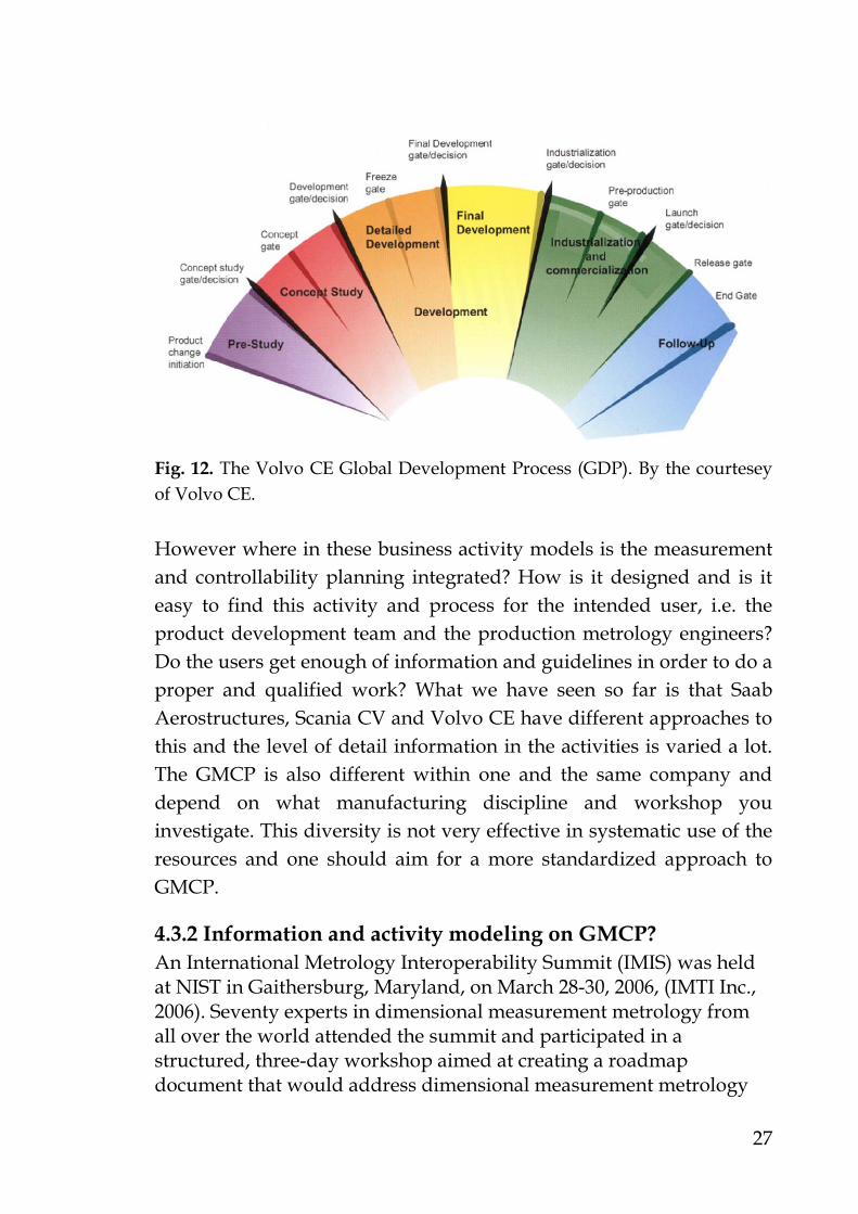
Fig. 11. The Saab Aerostructures business model. By the courtesy of Saab Aerostructures. In Fig. 11 we can see the Saab Aerostructures business model. This application and business model is accessible on the local Saab Aerostructures intranet. Each graphical item displayed in the model has clickable links that guides the viewer and user to the correct process of interest to be followed and executed. Each activity in the process is defined and links to relevant documents, i.e. standards, manuals and instructions etc, is given to the user. In Fig. 12 we can see an overview on Volvo Construction Equipment Global Development Process, (Volvo CE GDP, 2007). It displays the different phases with stage gates, from early product initiation or change through detailed development and industrialization to sustained production and follow-up.
27
Fig. 12. The Volvo CE Global Development Process (GDP). By the courtesey of Volvo CE. However where in these business activity models is the measurement and controllability planning integrated? How is it designed and is it easy to find this activity and process for the intended user, i.e. the product development team and the production metrology engineers? Do the users get enough of information and guidelines in order to do a proper and qualified work? What we have seen so far is that Saab Aerostructures, Scania CV and Volvo CE have different approaches to this and the level of detail information in the activities is varied a lot. The GMCP is also different within one and the same company and depend on what manufacturing discipline and workshop you investigate. This diversity is not very effective in systematic use of the resources and one should aim for a more standardized approach to GMCP.
4.3.2 Information and activity modeling on GMCP? An International Metrology Interoperability Summit (IMIS) was held at NIST in Gaithersburg, Maryland, on March 28-30, 2006, (IMTI Inc., 2006). Seventy experts in dimensional measurement metrology from all over the world attended the summit and participated in a structured, three-day workshop aimed at creating a roadmap document that would address dimensional measurement metrology

28
interoperability issues. The workshop was divided into four main topic areas regarding dimensional measurement metrology:
1. Product Definition, 2. Measurement Process Planning, 3. Measurement Process Execution, and 4. Analysis and Reporting of Quality Data
Interoperability issues can and do occur both within each of these four topics and when passing information between any two of the topicss. Fig. 13 below demonstrates the idea behind this way of thinking, (IMTI Inc., 2006). These interoperability problems have also been reported by Lindqvist et. al. (2009) and similar problem discussions regarding computer aided inspection planning and interoperability issues has been reported by Zhao et. al. (2009).
Fig. 13. The identified Metrology Interoperability Standards landscape in the year of 2006. (IMTI Inc., 2006) However, in the beginning of our research we observed there were few public and standardized instructions, information models and methods that supported the designers, production engineers and production metrology engineers performing GMCP, (Lindqvist and Vångell, 2008; Lindqvist et. al., 2009; Kihlander et. al., 2008; Savio et. al., 2007 ; Bagge, 2009). However, one good exception is the published

29
work by Feng and Horst at NIST, (Feng, 1994-1996, 1998, 2000 and 2007; Feng and Horst, 2007; SIMA, 1997), which has significantly contributed to the build-up of the BOK (Body Of Knowledge) and development of information activity models within this research area. As a result of the IMIS summit from 2006 a first project called HIPP (High-level Inspection Process Planning) started and one of the main topics was to develop an activity model for high-level inspection process planning, (Feng, 2007) †. An IDEF0 model was developed by Feng (2007). In Fig. 14 we can see the definition of the A0 level, “Perform High-level Measurement Process Planning”. This IDEF0 model covers five sub-levels: A1 - Determine Measurement Scope A2 - Determine Dimensional Measurement Method (optional) A3 - Develop High-level Dimensional Operation Plan (optional) A4 – Develop Reaction Plan (optional) A5 – Generate Support Data (optional) A1 identifies measurement requirements, determines measurement tasks and defines accuracy requirements. In A2 one selects gauge method and/or selects coordinate metrology method as well as choosing sensors for CMM application. A3 deals with probes setup and fixturing, features to be measured; sampling plan development and selection of evaluation functions and finally it covers high-level measurement operations. In A4 the measurement planner and the concurrent engineering team develops reaction plans and finally in A5 the measurement planner identifies what support data is to be generated.
† Inspection is in this case interpreted in a wider sense than normally used, and might be replaced by measurement.
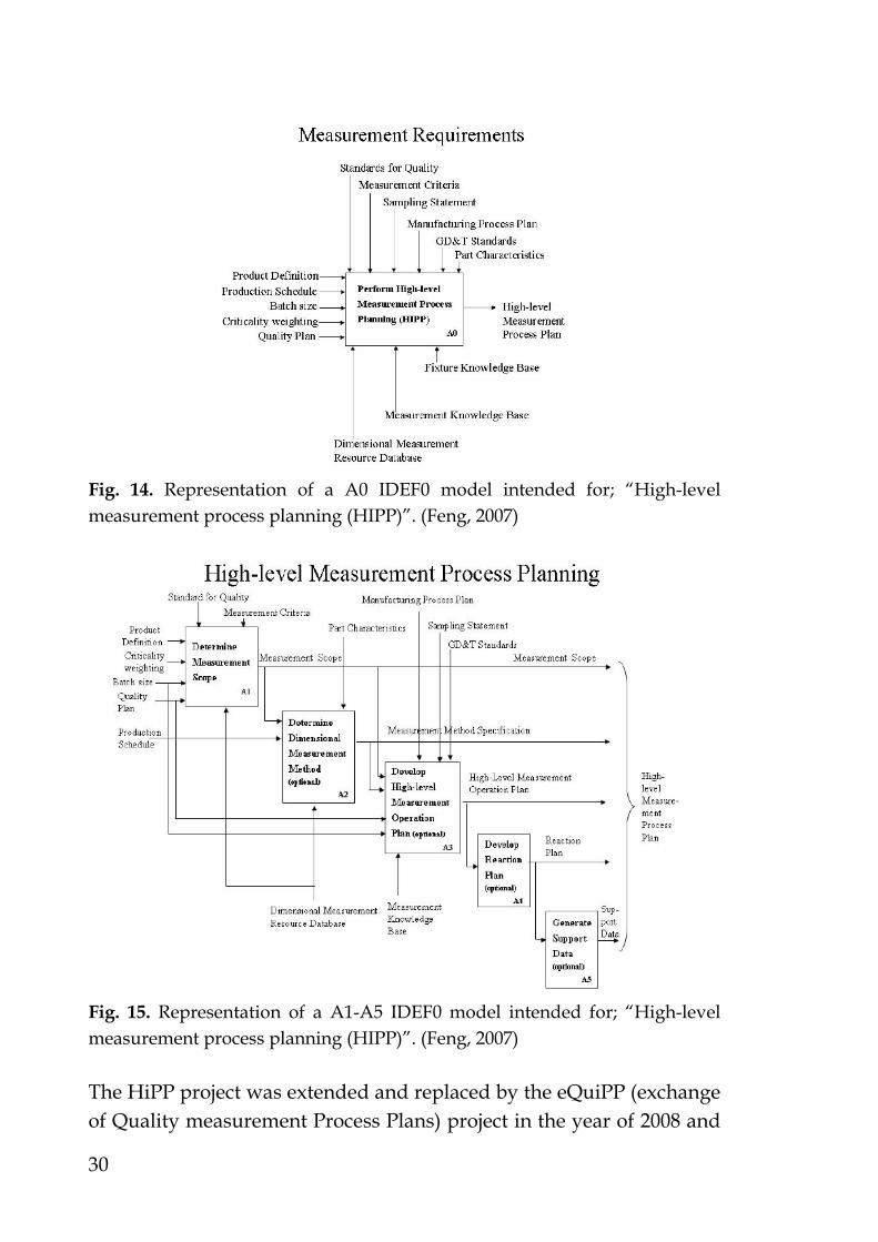
30
Fig. 14. Representation of a A0 IDEF0 model intended for; “High-level measurement process planning (HIPP)”. (Feng, 2007)
Fig. 15. Representation of a A1-A5 IDEF0 model intended for; “High-level measurement process planning (HIPP)”. (Feng, 2007) The HiPP project was extended and replaced by the eQuiPP (exchange of Quality measurement Process Plans) project in the year of 2008 and

31
later on in 2010 it was transformed into the QIF (Quality Information Framework) project, (Lindqvist et. al., 2010). The QIF project is the current running research project focusing on developing a standard, complementary to the STEP and DMIS standard, based on XML (eXtensible Markup Language). As reported by Lindqvist et. al. in (2009) Fig. 16 summarizes the eQuiPP developed intentions for interoperability issues and details what standards and protocols that are currently available and how they interact. It also addresses what standards and protocols that are missing and needs to be further explored.
Fig. 16. A representation of the eQuiPP consortium developed interoperability situation.

32
4.4 Academic and industry contributions
4.4.1 ASME standard B89.7.2-1999 - dimensional inspection planning
The only available standard found in the literature survey regarding geometrical and dimensional inspection and control planning is the ASME (American Society of Mechanical Engineers) B89.7.2-1999 and its primary sub reference ANSI/ASQC E2, “Guide to Inspection Planning”, (ASME B89.7.2-1999, 2000). This standard was a good attempt to start highlighting the importance of a structured way in performing dimensional inspection planning both for large companies as well for SME:s (Small to Medium size Enterprises). However, the standard has not been updated since its first edition, released in year 2000. The main section briefly describes what the dimensional inspection planner should consider, and it is a useful but far from complete reference guide to be used in today’s 3D MBD (Model Based Definition). It does mainly consider and focus on the planning of manual measurements.
4.4.2 The GPS handbook, SIS 545:2007 The handbook on GPS (Geometrical Product Specification), [SIS handbook 545; 2007], should be a mandatory guide and reference book for all Swedish design engineers, production engineers and production metrology staff. The ISO/TC 213, Geometrical Product Specification and Verification are the technical committee within ISO who constantly develops the GPS standard. In the GPS handbook the reader gets a very detailed orientation about how the GPS system is set up, its intentions and fundamental principles applicable on complex products and components. It also gives the reader an overview about the Swedish standard SS 2222, which is about technical documentation and how to classify and weight design and manufacturing requirements. The definition and orientation about the important production metrology related area uncertainty in measurements is also reported. This handbook is an excellent reference

33
guide for engineers engaged in product realization projects and has been a good input and reference to our research work.
4.4.3 The handbook on CMM metrology, SIS 543:2008 The handbook on CMM metrology, (SIS handbook 543; 2008), should also be mandatory guide and reference book for product realization engineers, and for Swedish production metrology staff working with CMM:s and portable CMM:s (PCMM). The handbook is published and issued by Swedish Standard Institute (SIS) and is an excellent reference guide for every production metrology engineer or technician working with CMM or PCMM technologies.
4.4.4 Technical specification ISO/TS 16949 The technical specification ISO/TS 16949, (SIS-ISO/TS 16949:2002; 2002), former known as QS9000, was primarily developed for the automotive industry suppliers. It is a detailed and structured approach to reach consensus and agreements on components to be manufactured by a supplier or sub-supplier. APQP (Advanced Product Quality Planning) and PPAP (Production Part Approval Process) is the major framework in ISO/TS 16949. PPAP is a major activity in the APQP methodology and process. The APQP and PPAP process is here generally described and the trend is that more companies adapt to this framework and implement it in its internal development processes. Both Volvo CE and Scania CV are on their way to integrate the ISO/TS 16949 in their organizations. Advanced Product Quality Planning (APQP) APQP is a structured approach to the design and development of new products and manufacturing processes, which especially has been developed to ensure that:
Suppliers understand the requirements of their customers (internal and external), end users and consumers.
The proposed product or process design satisfies the customer requirements.

34
The supplier has the ability to consistently meet the customers’ requirements for high quality, low cost and high delivery precision performance, i.e. key performance indicators (KPI).
The APQP process was developed by a consortia of automotive companies, and first published by the Automotive Industry Action Group (AIAG) in 1994, (APQP, 2008), and has since been adopted by many companies involved in the design and production of vehicles and component systems. APQP is now recognized in the ISO/TS 16949 as a possible customer requirement, and when specified it becomes mandatory for the component suppliers. Some of the key features of the APQP process include the following - The use of common terminology throughout the component supply chain, and the use of standard forms to document information regarding the product and process design, to ease communication with the supply chain partners. A process model for product development, which defines the expected inputs and outputs for each of the sub-processes, including:
Project definition Project planning Product design and development Design validation Process design and development Process validation Control plan methodology
The use of recommended tools and techniques to improve product, component and process quality incorporates: • Failure Modes Effects Analysis (FMEA) during system, product,
component and process design to identify and control identified risks. This includes both the design and process FMEA (D-FMEA and P-FMEA).
• Statistical techniques and statistical process control (SPC) to control process variation and minimize its impact on product quality and reach high capable production processes.
• Measurement system analysis (MSA) is used to ensure that measuring systems are repeatable and reproducible and allow non

35
conforming products to be detected, removed from production line and analyzed.
• A control plan methodology to ensure non-conforming products is detected and is not released and delivered to the next internal or external customer in the supply chain.
• Production Part Approval Process (PPAP). The purpose of the PPAP is to provide customers with evidence that:
Component suppliers have understood their requirements. The product meets the customer requirements. The production process is capable of consistently producing
conforming products. PPAP is an important part of the product development process, allowing producers to evaluate the components which they receive from suppliers, and establish confidence in the supplier's management systems. Although individual manufacturers have their own particular requirements, the Automotive Industry Action Group (IAAG) has developed a common PPAP standard as part of the APQP process and encourages the use of common terminology and standard forms to document project status. The PPAP process is designed to demonstrate that the component supplier has developed their design and production process to meet the customer’s requirements and thereby minimize the risk of failure by effective use of APQP. Failure to follow the agreed development process or keeping poor records during the PPAP process will undermine confidence in the quality of the supplied components.
4.4.5 SS-EN 9102 FAI and SS-EN 9103 VMKC Saab AB has access to the technical standard ISO/TS 16949 and uses it as a benchmark standard. However there are other similar standards and tools applied in the aerospace industry and examples on this are the Boeing Advanced Quality System (AQS) D1-9000-1 manual intended for the use within Boeing and for Boeing suppliers, (Boeing 1 and 2, 2006). Today there is SS-EN 9102 “First Article Inspection” and EN/SS 9103 “Variation Management of Key Characteristics” (VMKC) that dominates as guiding and mandatory standards in the aerospace

36
industry, (SS-EN 9102:2006, 2006; SS-EN 9103:2005, 2005). SS-EN 9102 FAI is used on components first article inspection. That means 100% verification is applied on the first articles being produced. While inspection planning is performed in SS-EN 9102 a certain FAI template is developed and used as documentation and for traceability purposes. While the FAI is executed in production the measurement planning for serial production has already been developed. Most of the metrology systems and manual gauges that have been selected and used in the FAI process are reused in the measurement planning of serial production. However not every metrology equipment used in FAI is reused in serial production, because in serial production effective and productive metrology should be applied. FAI is described as - One complete documented physical and functional verification of the process, the purpose of which is to verify that the prescribed production methods have produced an acceptable product that fulfills the requirements contained in engineering drawings, customer orders and other specified process requirements. The standard SS-EN 9103 is used for variation management of key characteristics. A KC (Key Characteristic) is defined as – The features of a material, process, or part whose variation has a significant influence on product fit, performance, service life, or manufacturability. In SS-EN 9100, (SS-EN 9100:2009, 2009), the following definition is given; Key Characteristics for part, subassembly or system are those selected geometrical, material properties, functional and/or cosmetic features, which are measurable, whose variation controls are necessary in meeting customer requirements and enhancing customer satisfaction”. Key characteristics for a process are those selected measurable parameters of a process whose control is essential to manage variation of part or system Key Characteristics. Substitute Key Characteristics may be identified when a customer-defined Key Characteristic is not readily measurable within the production setting and other characteristics may need to be controlled to ensure conformance. An example from Boeing AQS (Advanced Quality Systems) D1-9000-1 is displayed in Fig. 17. Here we can see an overview of the main process flow

37
describing how the identified key characteristics should be assessed and mitigated in production processes with the aim towards a robust and capable production processes.
Fig. 17. Boeing AQS process flow according to the D1-9000-1 requirement document. (Boeing AQS, 2006)

38
4.4.6 VRM – Variation Risk Management Another important contribution is the work on Variation Risk Management (VRM) by Thornton, (Thornton, 2004). In her book she presents a holistic framework to handle variation in product development up to production introduction. She proposes a model called the IAM process which includes three phases; Identification, Assessment and Mitigation. One of the important parts in her method is to take control over variations. She proposes a top-down structure called variation flow and the content of this flow includes:
Product KC (Key Characteristic) System KC Assembly KC Part/component KC Process KC External random disturbances/noises which cannot be
handled and controlled. This book has been important in the work of developing our GMCP methodology.
4.4.7 MPV – Module Property Verification Kenger (2006), manifests in his PhD thesis; “Module Property Verification”, that to guarantee quality - Inspection, verification and control activities need to be performed in a cost- and time efficient way. His contribution is a framework and a method to perform Module Property Verification. Instead of doing late verifications in the manufacturing and assembly processes he proposed more divided and frequent verification stations in the manufacturing and assembly line, as there is cost, time and quality benefits by introducing more frequent measurement stations up-front the production flow. He also identified in his literature review that there was a lack of information and knowledge models and methods on how to perform systematic measurement planning for both geometrical and dimensional verifications. For module property verifications he proposed a general verification process shown in Fig. l8.

39
Plan
Perform
Validate
Defect - Repair Ok - Delivery
What When How many
Inspection Control Test
Redesign Reassembly Rework Scrap -Replace
Adjustverification
Back toPerform verification
Fig. l8. A general verification process. (Kenger, 2006)
4.4.8 CAIP (Computer Aided Inspection Planning) systems In the area of CAPP (Computer Aided Process Planning) and CAIP (Computer Aided Inspection Planning) important state of the art surveys have been performed and published by Bagge (2009) and Zhao et. al, (2009). Bagge (2009) describes the current CAPP status and development efforts within the area and he proposes an approach to systematic operation and process planning in the machining of transmission components. Zhao et. al, (2009) give details about computer aided inspection planning systems for OMI (On Machine Inspection, also abbreviated OMV i.e. On Machine Verification) and CMM (Coordinate Metrology Machine) systems. They show the benefits and implementation requirements of OMI and they give detailed descriptions on early research, prior to the year of 1995, on CAIP systems. The CAIP research is divided into two categories; tolerance-driven and geometry-based CAIP systems. They also report

40
on recent and current research for OMI and CMM systems. They discuss the topics about inspection feature selecting and sequencing, measurement and sampling point’s selection and optimization for both OMI and CMMs and also included the findings on probing path planning and generation. Another important part is the discussion and development of neutral file formats, where they highlight STEP and specifically STEP-NC as an enabler for integrated inspection planning.
4.4.9 Software and file formats Software development in the GMCP area has been primarily related to geometrical and dimensional inspection planning of fixed as well as portable coordinate measuring machines, and a number of packages exist, e.g. AIMS (AIMS, 2009) and BCT Inspector [BCT, 2009] used mainly by the aerospace industries. The high volume automotive industries rely on CAD-plug in modules for measurement planning and probe path trajectories e.g. [Metrologiq, 2009; Wilcox, 2009; Zeiss, 2009). A problem with these metrology plug-in modules is that the CAD software is frequently updated while the metrology software is trailed behind, causing compatibility problems. An interesting research area is therefore the development of the neutral STEP and DMIS (STEP Tools, 2009; DMSC1, 2009) file formats, and especially the development of high and low level dimensional inspection planning processes. As previous mentioned and reported in chapter 4.3.2, NIST (National Institute for Standards and Technology) and the DMSC (Dimensional Metrology Standards Consortium) are doing research in the QIF project, aiming for implementing an interoperable standard for measurement planning.
4.4.10 Commercial proprietary GMCP software Today there exists some proprietary interesting software on the market for geometrical and dimensional measurement planning of CMM:s (Coordinate Measuring Machines) and PCMM:s (Portable Coordinate Measuring Machines) and manual gauges (such as calipers, micrometers etc.). Some of the available software’s will be briefly presented in this section:

41
AIMS AIMS (Advanced Integrated Mathematical System), (AIMS, 2009), “MultiCad” is a CAD (Computer Aided Design) file format independent software. It has a mathematical software kernel that can be integrated in different third party metrology software’s. This enables a seamless sharing of data and the possibility to; “close the loop of the digital thread”, and handle interoperability problems. Today it is being used by Lockheed Martin in its F-35 JSF (Joint Strike Fighter) program and the AIMS software is preferred and a prerequisite for suppliers delivering parts and components to the F-35 aircraft program. BTC BTC Inspector, (BTC, 2009), is a tool that facilitates the identification and extraction of valuable knowledge from the development environment and makes the data available throughout the entire lifecycle of the part. The data is available for quality assurance processes throughout the complete supply chain. The BCT Inspector process is supported for legacy raster data, 2D drawings and 3D model information. The BCT Inspector software supports a migration from traditional drawing based processes to model based information. It is a software module for the integration of quality management and first article inspection into the NX and Teamcenter product lifecycle management (PLM) environment. One reference user of this system is Volvo Aero in Norway. InspectionEasy™ The InspectionEasy™, (Inspectioneasy, 2010), software consists of two modules: the IDFCreator™ and IDF™ Poster. The IDF Creator is used for setup of inspection plans, create single or multiple phase inspection plans and establish variable, true-position or pass/fail check points over the imported drawing. Optical character recognition (OCR) speeds the set up by capturing target dimensions and tolerances automatically. The IDF Poster brings paperless data capture to the production floor. Operators capture inspection data through manual input or by more automated CMM:s or serial input measurement devices. Reports are generated for customers in

42
common formats such as SS-EN 9102:2006, PDF and others to aid in the quality control work and compliance issues. InspectionEasy™ was developed specifically for machine shops and manufacturing professionals. The software developers added many features designed in response to production customer needs. For example, if your poster station loses its network connection, data is automatically stored locally then synchronized when the network connection is reestablished. The software accommodates data in the exact sequence it is generated. "Turn Green" displays tell the operators that tolerances are checked and they can move on to the next operations. "Operator Check Lists" are a new feature which provides a print out of check points that can be used on the production floor. This allows operations without a poster station to collect data and have it manually typed in later or in the quality control office. Direct CAMS (Computer Aided Metrology System) software for inspection planning Much commercial and industrially available metrology software offer both on-line and off-line programming capabilities. A few of the suppliers are (Metrologiq, 2009; Verisurf, 2009; Wilcox, 2009; Zeiss, 2009). Experience gained from previous research (Lindqvist and Vångell, 2008) shows limitations in the interoperable reading of different CAD and neutral file formats. This is normally solved by an extra option from the software supplier and comes as a direct “CAD-plug in” module. This will also add an extra cost for the buyer of the software. Here is also a problem when the CAD software has frequent updates, while the industrial metrology software trails behind. This creates a compatibility problem or interoperability problem. One solution to this could be the use of neutral standard file formats such as STEP and DMIS.

43
4.5 GMCP applied in Swedish automotive and aerospace industry
In this chapter a review of the current state of the art in the Swedish automotive and aerospace industry regarding GMCP is presented. Hence, focus is on the participating manufacturing companies within the SIMET research project, i.e. Scania CV, Volvo CE and Saab AB. This chapter gives a broader and more applied viewpoint and analysis of the observed practical applications and ad-hoc solutions on GMCP seen in the industry today.
4.5.1 Scania CV (Automotive) On the quality assurance strategy in manufacturing and machining of complex transmission components, Scania CV has made development work during the past three years. Work related to gear manufacturing and process and operation planning, methods and tools, has been reported by Bagge (2009). This work is a good input to our research work on GMCP and QAM (Quality Assurance Matrix and methodology). In Scania´s vision towards zero defects in manufacturing of transmission components, Scania CV have gone from the following more reactive quality assurance and control system, Fig. 19, to a more proactive approach similar to what Shingo proposes (Shingo, 1986), Fig. 20. With more frequent measurement stations integrated in the production line the quality assurance systems becomes more proactive. Scania CV propose inspection by operators, so called self-inspection. However this is not according to the general standard working procedure and what Shingo taught about independent inspection. Shingo said, and this is a general rule in measurements, that all measurements should be performed independently. That is the operator responsible in a specific machine should not perform inspection on his own work. This should be done independently by another operator or quality technician.

44
Fig. 19. Scania CV quality assurance process, current state.
Fig. 20. Scania CV quality assurance process, proposed future state.

45
Scania CV is actively and continuously working with actions towards the goal of zero defects in component manufacturing. The strategy and actions include some of the following topics:
Automatic SPC (Statistical Process Control) o Control limits within 70% of the specified design or
manufacturing tolerance Storage of measurement data, which leads to:
o Easier to plan and work proactively o Easier to optimize the production process, for example
knowledge about how often and when to change a cutter in the machine tool.
Continuous machine and process capability follow-up o Easier to work proactively with improvements on the
quality assurance system. Feedback in realtime
o Faster actions on manufacturing defects which leads to reduced waste.
o Leads to more effective and productive manufacturing operation
Most of the design and manufacturing characteristics can be measured in-line for product verification and SPC.
4.5.2 Volvo Construction Equipment (Automotive) At Volvo CE in Eskilstuna the production of complex machined components has been studied. Typical components are transmission parts for gear boxes, axles and different housings. In general, the measurement and inspection of manufactured components is divided into four different topics and activities:
1. First Article Inspection 2. Verification by sampling 3. Verification by operator 4. Final verification
First Article Inspection - Means that the first manufactured component in a batch is measured in order to verify it is in accordance to the drawing specification. The verification methods of the component should be representative to serial production methods. The production leader is responsible for the first article inspection and that it is being performed with approved results. The operator, measuring technicians and production leader has the authority to

46
perform the first article inspection. This should always be performed when:
A new production order is launched Major tooling changes occur Collision or major breakdowns has happened in production
machines Operations are moved from one machine tool to another one
First article inspection can be performed manually with manual hand gauges, automatically in a CMM machine or in a combined way. If there is no other recommendation, the operation description should act as the guidance on how to perform first article verification. Verification by sampling - Verification by sampling assures that the quality of manufactured components is monitored. The sampling frequency is adapted to the specific process capability and its economical impact if an error occurs. Expensive components and components with machining operations that has a significant impact on the quality output will have a higher inspection frequency Verification by operator - The operator is responsible for that his/hers work is being verified. In order to do this and follow this principle, the operator has measurement instructions and operation description to follow. Final verification - Final verification is performed directly after the final manufacturing operation of the component and the purpose is to prevent that component with defects is delivered to the storage or direct to assembly. Component deviations are reported to the production leader at the specific section of the line. The results are documented and archived. The components are also ocularly inspected in order to catch any possible deviations regarding scratches, burrs, dirt and other possible contaminations. Different manufacturing departments at Volvo CE have been investigated and the conclusion is that the previous working practice and applicable work instructions is different between the studied departments. Some departments have developed very detailed instructions on when, how, by whom etc. the work should be carried out. Nevertheless, the following proposal for improvements has been identified:
In the industrialization phase, always describe and state the total number of parts/components to be manufactured in a
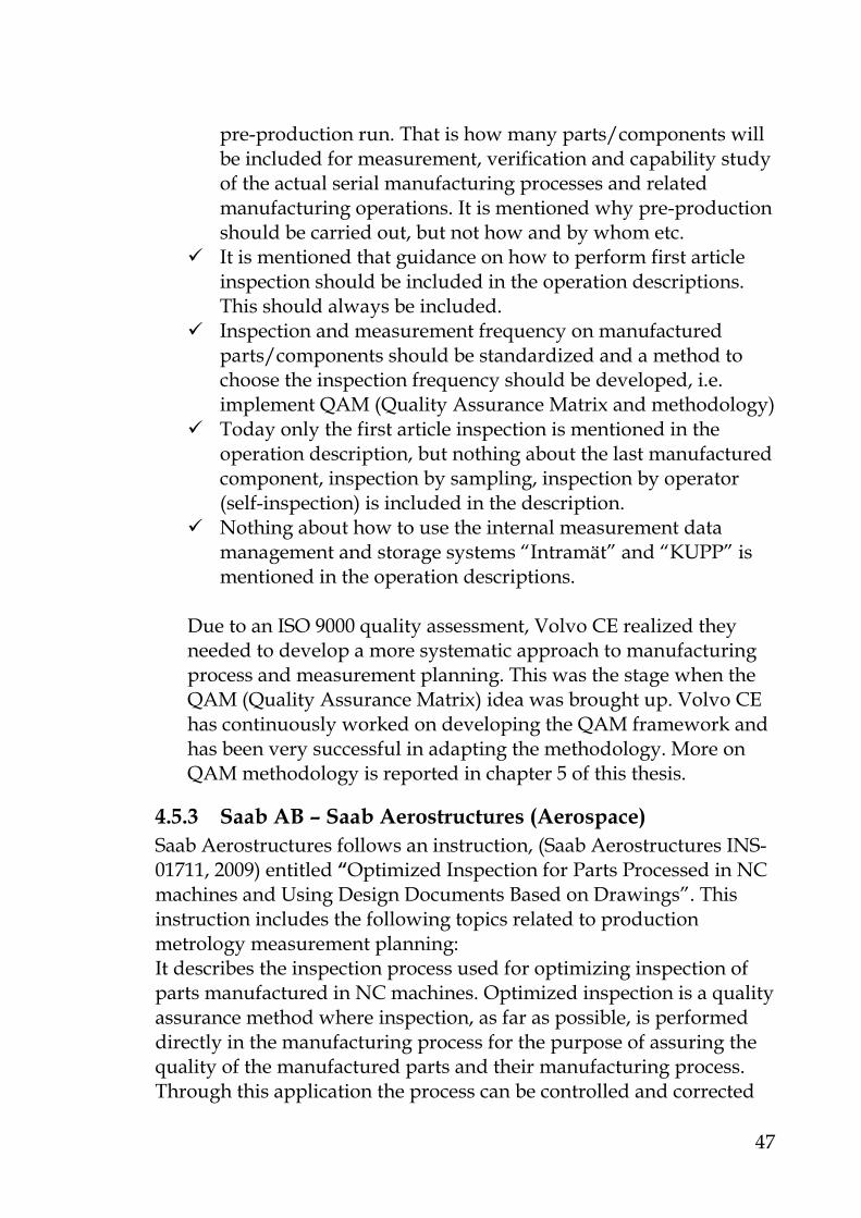
47
pre-production run. That is how many parts/components will be included for measurement, verification and capability study of the actual serial manufacturing processes and related manufacturing operations. It is mentioned why pre-production should be carried out, but not how and by whom etc.
It is mentioned that guidance on how to perform first article inspection should be included in the operation descriptions. This should always be included.
Inspection and measurement frequency on manufactured parts/components should be standardized and a method to choose the inspection frequency should be developed, i.e. implement QAM (Quality Assurance Matrix and methodology)
Today only the first article inspection is mentioned in the operation description, but nothing about the last manufactured component, inspection by sampling, inspection by operator (self-inspection) is included in the description.
Nothing about how to use the internal measurement data management and storage systems “Intramät” and “KUPP” is mentioned in the operation descriptions.
Due to an ISO 9000 quality assessment, Volvo CE realized they needed to develop a more systematic approach to manufacturing process and measurement planning. This was the stage when the QAM (Quality Assurance Matrix) idea was brought up. Volvo CE has continuously worked on developing the QAM framework and has been very successful in adapting the methodology. More on QAM methodology is reported in chapter 5 of this thesis.
4.5.3 Saab AB – Saab Aerostructures (Aerospace) Saab Aerostructures follows an instruction, (Saab Aerostructures INS-01711, 2009) entitled “Optimized Inspection for Parts Processed in NC machines and Using Design Documents Based on Drawings”. This instruction includes the following topics related to production metrology measurement planning: It describes the inspection process used for optimizing inspection of parts manufactured in NC machines. Optimized inspection is a quality assurance method where inspection, as far as possible, is performed directly in the manufacturing process for the purpose of assuring the quality of the manufactured parts and their manufacturing process. Through this application the process can be controlled and corrected

48
as early as possible. The method is divided into steps, depending on whether the part to be manufactured, measured and inspected is a new part, or whether it has been manufactured before and the process has been guaranteed and proven to be capable. The different steps are described as the following:
First work order and FAI. This is an inspection carried out by the inspection department to guarantee that the program and tools used in the manufacturing will produce a part that conforms to the requirements contained in the manufacturing documents. It also shows that the process is repeatable and capable.
Serial measurement. This measurement is performed by the measuring department on the first and last parts manufactured in every batch. Its purpose is to confirm that the first and last parts in the batch conform to the manufacturing documents, and that the process has been stable during the course of manufacture.
TMA inspection. This inspection is included as a part of serial measurement and is performed by the machine operator. Measurement is performed on all parts manufactured in the batch to check that the process is stable during the full course of the manufacturing.
Measurement planning of new components to be manufactured is based on full 3D MBD (Model Based Definition). In this case Hexagon PC-DMIS is being used as off-line programming software. In general the new MBD methodology is estimated by the Saab engineers to cut the lead-time for planning and programming activities by approximately 60% compared to the previously used methodology.
4.6 Summary and concluding remarks on chapter 4 In this chapter we have reported on the current status and state of the art in industry as well in academia on the research and on the current use of GMCP. The Swedish automotive and aerospace industry use different standards but similar approaches to measurement planning. The trend in the automotive industry is that they are adapting to the ISO/TS 16949 standard and in the aerospace industry they have adapted to the SS-EN 9102 and 9103 standards as guidelines and mandatory framework.

49
5 Theory and model framework for GMCP
“Essentially, all models are wrong but some are useful.” George E.P. Box
5.1 Production metrology in component manufacturing
In order to ensure final product quality, manufacturing enterprises must measure the geometrical and dimensional quality of components before they go into higher-value assemblies. Commonly dimensional measurement and verification occurs every time a new machining set-up is initiated, a line is restarted or if the production process is changed.
One important role of production engineering metrology is to achieve quality control loops between the following engineering disciplines: design, manufacturing, quality, measurement planning. This includes knowledge based support on how to: set correct tolerances, create measurement plans and procedures by using GD&T (Geometric Dimensioning and Tolerancing), and how to invoke surface structure requirement information inherent and annotated in the 3D CAD models. Production quality and quality assurance activities will be improved by the development of measurement methods and analyzing tools that feed measurement result back into design and manufacturing and product development. One example of a company that is using this approach is Volvo CE in Eskilstuna; see appended papers A and C for a more detailed description on their approaches. Volvo CE has developed a methodology and tool called QAM (Quality Assurance Matrix). The QAM tool is used in their product development work and in very early phases of product development. However, in order to grasp the engineering disciplines in a manufacturing company and how they interact to each other the following figure, Fig. 21 is presented. It represents the future vision on a quality assurance system in product development and

50
manufacturing. In this figure we can see different activities in design and manufacturing development and what their intentions are. In this context we see where the QAM methodology and tool is mainly being used in the integrated product development teams.
Fig. 21. The main activities in product development, industrialization and reuse of design and production knowledge. Besides the understanding of process concepts for quality assurance and improvement, it is also rather important to pay attention to the 6M:s impact on defects which is caused by errors, (Six Sigma, 2011): How does Man (People) introduce errors into the component? How do the Machines introduce errors into the component? How does the Material introduce errors into the component? How do the Methods introduce errors into the component? How do the Measurements introduce errors into the component? How does Mother Nature introduce errors into the component?
We cannot always completely build totally failsafe, i.e. Poka-Yoke, (Shingo, 1986), production systems for component manufacturing, although there is existing examples on failsafe machine tool solutions at Saab Aerostructures for airframe component manufacturing. So the need for efficient and productive production engineering metrology will still be in great demand.

51
5.2 Information modelling approach
5.2.1 Information and activity modeling In her doctorial thesis work, Von Euler-Chelpin (2008), describes information modeling and its relations to development of general theory in a very confined and distinctive way. She says; ”Information modeling typically involves the need to identify what information needs to be handled, and to choose or design an appropriate model for this information. If one has information modeling as a research area it will make it hard to apply a deductive approach, since the art of modeling and managing information is not usually expressed by general theories or truths. Another reason that makes generalizations difficult is that information modeling is a very subjective task. A model depends not only on the purpose of the model but also on the observer and/or the modeler. Further, it is in the nature of information representation that there are no rights or wrongs; there are only imperfect or less imperfect ways, and its level of “correctness” is fuzzy and difficult to evaluate...”,. Fig. 22 shows how the information management process is contained in different development steps, (Von Euler-Chelpin, 2008).
Fig. 22. The scope and process for information management. (Von Euler-Chelpin, 2008) It is our opinion that this description by Von Euler-Chelpin (2008) contextualizes information modeling in a distinctive and well defined way. The following sections in this thesis will describe our approach to information and activity modeling of GMCP activity and process models. The approach of activity modeling is a good way to describe

52
what and how, by whom, when and where etc. a certain engineering task should be carried out. However, the GMCP process in product development work is not always a serial process. It is a combination of serial, parallel and iterative activities forming a process. It is easy to think that a described activity model or process is serial because it is often visualized and presented in that way, despite being an iterative process with feedback loops.
5.2.2 Measurement process planning and model driven process planning
Process planning is a central and complex activity in a manufacturing company. During process planning many decisions are made mainly based on experience, e.g. concerning the choice of the right type of process, sequence planning, appropriate fixture design, measurement planning and control etc. However, process planning may also result in the need for changing the factory layout or trigger investments in new machines, (Lindqvist et. al., 2008). Model driven process planning activities utilize a common three dimensional digital product model with defined geometry, dimensions and tolerances. Process planning is performed using models which describe the product and the manufacturing processes, supported by models of machine tools, fixtures, cutting tools, production metrology equipment. (Lindqvist et. al., 2009) In our research we have chosen to use the modeling language called ASTRAKAN, (ASTRAKAN, 2009). This modeling language is suitable to model processes which are common in larger manufacturing companies, (Volvo CE GDP, 2007; Business Modeler, 2010). In the ModArt (Model driven part manufacturing) research project one of the main goals was to develop information models, see Fig. 23, to be used as guides in companies as well in academy for educational purposes, (ModArt, 2011).

53
Fig. 23. Screen capture of a web-based guide, the example show the work instruction web-based guide. (Production Guides, 2009)
5.2.3 Activity modeling methodology The Astrakan modeling language is developed out of IDEF0 and IDEF3 modeling languages. When using ASTRAKAN, you model a process or processes containing activities. Activities have inputs and outputs and frequently some controlling features and some supporting features. In order to model the information models we used the Microsoft Visio™ as the software tool. Fig. 24 illustrates the basic principles on how to model processes and activities by the use of the ASTRAKAN modeling language.

54
Fig. 24. The basic principle of ASTRAKAN modeling
5.2.4 GMCP information model and relation to QAM? The holistic view in our information model is the approach to concurrent engineering work and the interaction between different skills and disciplines, i.e. design, manufacturing, process engineering, fixture design and development, instruction development and industrial metrology. Fig. 25 shows the holistic model approach.
with activities

55
Fig. 25. A holistic model approach where Inspection and Measurement Planning is one important and key enabling functional competence. In our detailed GMCP model we have tried to capture and mix the good ideas behind the methodology and theories about QFD (Quality Function Deployment), (Akao, 2004), Design FMEA (Failure Modes and Effect Analysis), (APQP, 2008), including a design classification of all design features and characteristics that needs to be inspected, measured, controlled, monitored and tested. Process FMEA is also integrated and process classification, along with a calculation of the risk for a geometrical and dimensional deviation not being detected in the manufacturing process is also included in the model. During the course of this research work we have developed several different versions of the GMCP information model. At the beginning the information model was very extensive in contents and physical size and it is quite difficult to comprise all that developed and synthesized information simultaneously with the knowledge on one page. That is why we try to communicate the information contents by the following textual description of the GMCP model.

56
The model is based on QAM (Quality Assurance Matrix and methodology) which was originally an idea derived from Volvo CE in Eskilstuna, Sweden. Fig. 26 shows the simplified and rather condensed version of the GMCP model. It contains inputs with operation and manufacturing sequences and classified critical design characteristics. The control features contains target values on corrected capability index and a general guideline on acceptable measurement uncertainty. The supporting features are corrected capability indexes taken from a company machine and process capability management database system. The output from the activity is - measurement verification operators, process relations and a systematic measurement plan.
Fig. 26. The condensed version of the high-level GMCP information model.
5.3 Development of a detailed QAM methodology In order to achieve and manufacture high quality components, off-line measurements in dedicated qualified measuring rooms is currently used to guarantee and to control the conformance of the component. On the other hand in-line measurements are used to assess the robustness and capability of the machining operations in the specific
Develop GMCP concept

57
machine tools. The future challenge within production metrology will be to address the need of a faster and less costly component and production process realization. The rapid adaption and use of scanning metrology instead of traditional discrete, “point by point” measurement will increase in use. With these facts in mind and also considering the gap and roadmap analysis presented in chapter 3.3.2, the QAM methodology was explored and developed.
5.3.1 What questions should always be asked in measurement planning?
What is important in measurement and inspection planning? What activities should be carried out and what questions should always be asked and questioned during the GMCP process work? In an answer to these questions we have found out that the following questions should be mandatory when performing holistic and systematic GMCP work: What should be measured and verified or controlled and monitored in the machining process? How important is the specification operator, verification operator and does it exist any design and manufacturing classification on the specific requirement? Is the specific verification operator (measurand) measureable? What defined design specification and metrology verification uncertainties exist and how do we minimize the errors in making them to conform to each other? This should be in accordance to the standards developed by the ISO/TC 213 “Geometrical Product Specification and Verification”? Why(×5) should the measurement be done and what is the level of importance? Where in the machine tool or in a specific operation, on the machine tool or off-line in a measuring room? How – Manually, semi-automatic or fully automatic? With what metrology equipment should the measurements be carried out? - CMM, Portable CMM, hand gauges etc. and/or combinations of them? How is the metrology equipment chosen and is it done in a systematic way? As guidance the metrology equipment should have a tolerance which is 10 times lesser than the specified design or manufacturing tolerance.

58
With what uncertainty, stability, validity and traceability is the production measurements carried out? How is this calculated, predicted and physically validated and verified? When will the measurements be carried out? Is it according to the current production rate and planned tact times? How frequent will the measurements be carried out? Every each component, or every 10:th etc. and how many, i.e. what sample size? Who will be performing the measurement? And how does he or she know what to measure and what is important to know when taking measurements? This sets requirements on competence profile, and requirements on education, and need for qualification?
5.3.2 Understanding critical and non critical requirements It is very common in the automotive industry that they use some kind of design classification system. Both Scania CV and Volvo CE have developed their own classification systems. Saab AB also uses a classification system though it is diversified between different projects within Saab AB. In Fig. 27 we can see an example on Scania CV´s COR (Classification Of Requirement) system and how it is indicated on the drawings. The classification is divided into critical, major and standard requirement and a statement on how each category should be interpreted. This classification is a good input for the measurement planning and outlines to the concurrent engineering group what to focus on and how to prioritize when performing measurement planning. This could be supplemented by a manufacturing classification of the broken down design classification requirement and also act as a good input to the measurement planning process. Volvo CE uses a similar classification system, Volvo standard 105-0001, but they have numbered the requirements by numbers 1-4 where number one is the most critical and number four is the least critical. If the classification is judged to a number 4 then it is treated very openly and with high freedom. If this kind of classification systems is always applied on products and components this will extensively simplify the work for the manufacturing and metrology planners as well for the entire concurrent engineering development team.
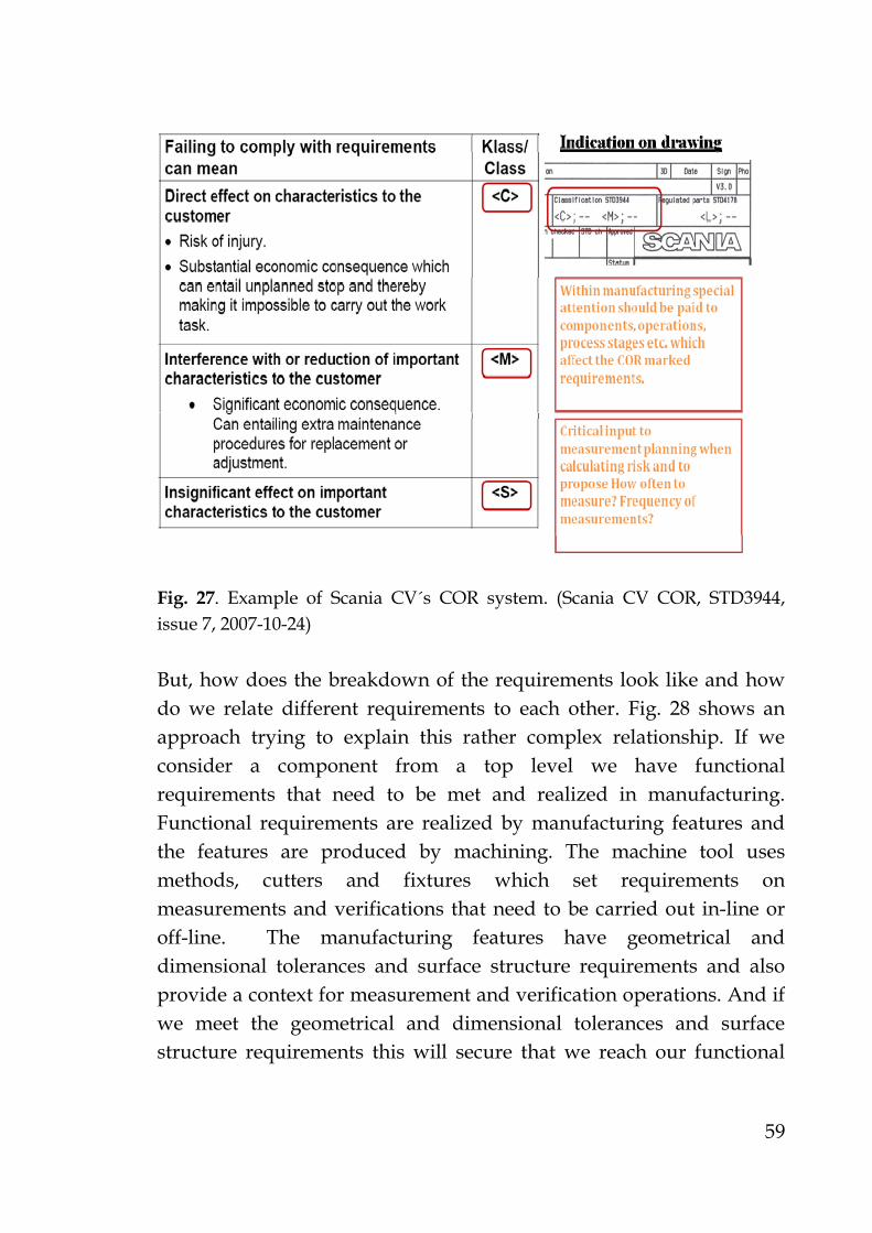
59
Fig. 27. Example of Scania CV´s COR system. (Scania CV COR, STD3944, issue 7, 2007-10-24) But, how does the breakdown of the requirements look like and how do we relate different requirements to each other. Fig. 28 shows an approach trying to explain this rather complex relationship. If we consider a component from a top level we have functional requirements that need to be met and realized in manufacturing. Functional requirements are realized by manufacturing features and the features are produced by machining. The machine tool uses methods, cutters and fixtures which set requirements on measurements and verifications that need to be carried out in-line or off-line. The manufacturing features have geometrical and dimensional tolerances and surface structure requirements and also provide a context for measurement and verification operations. And if we meet the geometrical and dimensional tolerances and surface structure requirements this will secure that we reach our functional

60
requirements on our component and this will close the functional breakdown requirement loop on our component.
Fig. 28. Functional breakdown and interrelationships. Note: Inspection has been replaced by verification.
5.4 Description of the QAM tool and methodology In appended paper A and C of this thesis the reader can get more detailed description of the QAM application and methodology. In this chapter we give a brief summary of the application and description of the methodology. The QAM methodology as introduced by Volvo CE is performed in a developed Microsoft Excel™ application. The QAM methodology is described as follows: 1. Use the Critical Characteristics, which as an example is described
and expressed in Volvo standard 105-0001, as a key input for each specification on the drawing together with the knowledge of risks occurring in the manufacturing operations. This is a way of doing a Process-FMEA, but the major difference is that the view is on the

61
components perspective and every specification is handled by a cross functional team in a cost effective way.
2. While the ability to measure is valued in the QAM methodology a quality assurance of the drawings with respect to the specification uncertainty is performed. Through the work in integrated product development teams consisting of members from product design department, manufacturing engineering, production leaders, measurement technicians and operators, the QAM work methodology enables a company to decrease and minimize specification uncertainty in a systematic way. All possible actions detected by the use of the QAM methodology is logged and investigated.
3. By the use of those characteristics which provide the best information about the different production methods, their robustness and capabilities, a systematic choice of geometry assurance philosophy can be performed. Optimal possibilities to secure manufacturing methods in very early stages of the product development are thereby achievable. In the mean time geometry assurance activities will provide and create conditions for workshop operators to control and manage the quality outputs from their machine tool process as well as provide input for measurement planning and quality control activities. This geometry assurance activity is essential and of central importance because the quality of each individual geometry feature will set the limits on how well the features can be controlled as well as what measurement methods can be used to verify and monitor the features.
4. Controllability for each dimensional feature is valued, features created in manufacturing and which is controllable is controlled and monitored by the workshop operators and that features that has been secured by the machine itself and is not controllable is monitored by the systematic developed control plans.
5. By the use of QAM, statistical control methods and machine- and process capability follow-up is investigated and decisions are taken on where it should be used in the production process. Also the correct software tools and support software for calculating the correct capability indexes are chosen. One should observe that the inherent geometrical and dimensional features can be valued and investigated in this stage, of the entire component.

62
6. The output from the QAM application is a systematic measurement and control plan, listing all identified verification operators and their manufacturing process relationships. The manufacturing process relationship gives us information on where the specific manufacturing feature is created and where we should keep extra focus in the process in order to secure the geometrical and dimensional characteristic of that specific feature. We also identify suitable production metrology equipment and a special section where all applicable and identified geometrical and dimensional features to be verified and monitored is compiled, i.e. dimensional, GD&T (Geometric Dimensioning & Tolerancing) and surface texture information. This means it will be much easier to immediately identify and analyze what kind of knowledge, the level of knowledge and the acute need for competence development and education among the influenced employees that really needs to be carried out.
In context the six points listed above tells us how the QAM methodology is working and how it is performed in product development teams.
5.5 General principles and rules in GMCP What is controllability and non controllability? Controllability is defined as; a machining process can be verified during the process and be adjusted to correct tolerance by the input from the measured dimensional feature. Imagine a precision hole that is manufactured by the use of an adjustable reamer in this case the hole could be adjusted and corrected according to the captured in-process measured value during the actual machining of the component. In general, controllability is valid for most of the manufactured dimensional features in machining. Non controllability is referred to features that not easily could be controlled and adjusted during machining operations. This is typically most of the GD&T features like positional and form characteristics. These GD&T characteristics are typically embedded in NC-programs, jigs and fixtures. That is why one should focus on the non controllable features in the prototype and pre-production programs, because

63
controllable dimensional features are as a basic rule generally easier to control in machining.
5.6 Summary and concluding remarks on chapter 5 In this chapter we have reported on the current research carried out within the SIMET project. We have presented an information activity model approach for GMCP and we have also further explored the QAM tool and methodology. The question about critical and non critical requirements on characteristics has been discussed. The most important questions to ask and to answer in GMCP have been highlighted and we have also presented the general principles and rules in GMCP.

64

65
6 Results and discussion
6.1 The QAM tool and methodology By the application of a tool and an integrated methodology called QAM (Quality Assurance model and Matrix), the results at Volvo CE in Eskilstuna has so far shown the following qualitative results, (paper C):
Changed design engineering, production engineering, and production metrology and related drawing requirement specifications, i.e. according to ISO/TC 213 “Geometrical Product Specification and Verification” defined; specification and verification operators.
New or changed selection of applicable measurement type, measuring method and dimensional metrology equipment.
A first proposal on a suitable sampling or measurement frequency strategy based on the risk assessment and identified current available machine and process capability in production.
According to Volvo CE, the following quantitative results (as of February 2008) have been achieved:
In total 130 QAM´s has been started. (i.e. 130 components has been analyzed and planned).
Drawing related problems and actions has ended in: 653 design engineering actions 435 production engineering actions. Measurement and controllability (GMCP) related activities and
problems have ended in 166 actions. Process and operation planning related activities and problems
have generated 666 actions. Material and purchasing related activities and problems have
generated 2 actions.

66
6.2 The eQuiPP standardization project
6.2.1 Results Starting in 2010 the eQuiPP, today known as QIF, technical committee has begun to meet in order to define a specification which for the first time promises to standardize all measurement process planning, information which is necessary for checking key characteristics on products and components. This will allow the definition, in a standard computer-readable language, of any quality-related requirement coming downstream from ISO 9000/9001 (and others ISO, ANSI and/or ASME related) quality standards. Therefore, eQuiPP has relevance to a very large sector of business and manufacturing. In appended paper C we present the eQuiPP standardization project.
6.2.2 Discussion Effective development tools for eQuiPP are attaining high interest and priority among the manufacturing industry management and this is due to the increased demands and focus on cost reduction, standard quality work and the aim towards zero defects in manufacturing. Success with information standards like eQuiPP starts with real market needs and a recognition of that need by a critical mass of end users, tier suppliers, and system vendors. The effort continues with the definition of a correct, complete, and unambiguous specification. The work ends with standardization, compliant implementations world-wide, public interoperability tests, and a certification program based on conformance tests. Actually, the work never ends, since a standard must grow and change with technologies and markets, but the intensity of the effort abates after the first few versions achieve international standardization. Many of the essential requirements are in place in the eQuiPP effort. The quality measurement experts currently working on eQuiPP have had a long and varied experience with both the technical and cultural sides of defining and implementing quality measurement information standards.

67
6.3 Summary and concluding remarks on chapter 6 In the suspense of project results from eQuiPP, the research presented in this licentiate thesis has focused mainly on exploring an information model and a tool and methodology called QAM. According to Volvo CE in Eskilstuna the explored QAM tool and methodology has proven to be a suitable tool in their measurement planning activities.

68

69
7 Conclusions and future work
7.1 The automotive and aerospace industry challenges
The automotive and aerospace industries have for a long time faced a dilemma. Given the critical nature of the final products they build, all sub-assemblies and components need to be free of defects. However, manufacturers and suppliers need to keep their costs down and efficiency up in order to remain competitive in the marketplace. The future of production measurements in the automotive and aerospace industry is challenging, as there is still quite a lot of challenging tasks and problems to be solved. The constantly evolving production metrology development in both hardware and software put pressure on the developers in the automotive and aerospace industry to reach at least the level of state of the art technology in order to stay competitive and sustainable. The treatment of measurement data and an efficient incorporation of it in the production processes are a true challenge for the industrial users of metrology systems.
7.2 Productive production metrology High speed scanning technologies are offering capabilities to capture huge amounts of geometrical and dimensional data in a very short time. The current systems are offering possibilities for industrial manufacturers to control and monitor and assist manufacturing processes. This will reduce time and cost, and increase the accuracy and feasibility of the manufacturing methods. Nevertheless, creating data files of millions of 3D points creates new challenges in information storage, management, and what is more important, in the analysis and transformation of the measurement data in useful knowledge. New methods of data analysis and processing are needed, not only to be able to summarize the data in a valuable and useful format, but also to optimize the use of the systems by the engineering teams.

70
7.3 The GMCP information model and QAM methodology
This licentiate thesis has described research activities and the industrial and academic need for a developed information model and methodology, describing in a holistic way the systematic geometrical and dimensional measurement and controllability planning of complex components. Finally, after many workshops and industry discussions one, simplified, proposed activity model, developed by the use of the ASTRAKAN modeling language, was proposed and presented in this thesis. An introduction to a specific methodology and tool called Quality Assurance Matrix and methodology (QAM) has also been presented. The current developed information model have so far been implemented and tested in one industrial and one academic project. More implementations in order to validate, verify, falsify and evaluate the developed activity model and QAM methodology are expected to be performed in the continuation of this research, i.e. in the SIMET-GICP project. Further research and linkage between the information model and the QAM methodology needs to be performed in order to bridge them into a more comprehensive and smoother framework for geometrical and dimensional measurement and controllability planning work.
7.4 The international QIF standardization project The former eQuiPP and HiPP project, now known as the QIF project, comprises and includes members and manufacturers such as NIST, KTH, Honeywell, Lockheed Martin, Saab AB and John Deere, along with metrology vendors such as Siemens PLM, Mitutoyo, Renishaw and Hexagon. The eQuiPP (exchange of Quality Measurement Process Plans) specification is proposed as an international standard which will reduce interoperability costs. The actual cost resulting from the lack of standardization is most likely enormous even though this cost is difficult to quantify. The primary scope of this new proposed standard is currently an XML (eXtensible Markup Language) based quality measurement plan, with an export format for variable and attribute measurement and inspection plan processing.

71
7.1 Summary and concluding remarks on chapter 7 In this chapter we have reported on the conclusions and future work. In the continued research work in the project called SIMET-GICP we will implement and further explore the QAM tool and methodology at the Swedish automotive companies Scania CV, Volvo CE and LEAX. In the aerospace industry we will implement and evaluate the QAM tool and methodology at Saab Aerostructures. In the international standardization project called QIF, KTH and the institution of production engineering and the SIMET forum will take a more active role as a member of the project committee.

72

73
References AEM. Aerospace Engineering and Manufacturing Online. 2008-10-22. URL: http://www.sae.org/mags/AEM/4681 AIMS (Advanced Integrated Mathematical System) information page. 2009-05-16. URL: http://www.aims-metrology.com/ Akao, Y. “Quality Function Deployment: Integrating Customer Requirements Into Product Design”. ISBN 1563273136, 9781563273131. Productivity Press, 2004. APQP, “Advanced Product Quality Planning (APQP) and control plan”, second edition, 2008. ISBN: 978-1-60534-137-8 ASME B89.7.2-1999. Dimensional Inspection Planning. The American Society of Mechanical Engineers, March 1, 2000. ASTRAKAN. Information Process Modeling. In Swedish. 2009-05-20. URL: http://www.astrakan.se/ Bagge, M., (2009) “An approach for systematic process planning of gear transmission parts”. Licentiate thesis. Department of Production Engineering, KTH, Stockholm. BCT. By BCT Technology AG. 2009-05-18. URL: http://www.bct-technology.com/en/products-solutions/bct-software-products/bct-inspector-suite.html Boeing (1) Advanced Quality Systems (AQS) Tools. Document identification number: D1-9000-1, 2006. URL: www.boeing.com/companyoffices/doingbiz/.../d1-9000-1.pdf Boeing (2), “Variation management of key characteristics (AS9103) evaluation”, fifth edition, 2006. URL: http://www.boeing.com/companyoffices/doingbiz/supplier/VMKC_Tool_10_04_06.pdf Business Modeler, (2010). Software tool for activity and process modeling development. URL: http://www.businessmodeler.com/?page=1 Carlsson, T., (1999), “Verkstadsmätteknik”. Book in Swedish. ISBN 91-47-01304-4

74
Cho, M-W., Lee, H., Yoon, G-S., Choi, J. “A feature-based inspection planning system for coordinate measuring machines”. Int J Adv Manuf Technol (2005) 26: 1078–1087. DOI 10.1007/s00170-004-2077-8. CleanSky, (2009). http://www.cleansky.eu/ DMSC (1). Dimensional Metrology Standards Consortium information page. 2009-05-18. URL: http://www.dmisstandard.com/ DMSC (2). Dimensional Metrology Standards Consortium. eQuiPP information page. 2009-05-18. URL: http://www.dmisstandard.com/eQuiPP/ Feng, S., (2007), “HiPP Activity Model”. Joint DMSC and the 53rd ISO/TC184/SC4 meeting in Irving, Texas, USA. Feng. S., "Manufacturing Planning and Execution Objects Foundation Interfaces", 2000. Journal of Manufacturing Systems, Vol. 19, No.1, pp. 1-17. Feng, S. and Zhang, C., "A Modular Architecture for Rapid Development of CAPP Systems for Agile Manufacturing", 1998. IIE Transactions Focused Issues on Design and Manufacturing, Vol. 30, pp. 893-903. Feng, S., "A Dimensional Inspection Planning Activity Model", 1996. Journal of Engineering Design and Automation - special issue on Tolerance and Metrology for Precision Manufacturing, Vol. 2, No. 4, pp. 253-267. Feng, S. and Yang, Y. "A Dimensional and Tolerance Data Model for Concurrent Design and Systems Integration", 1995. The SME Journal of Manufacturing Systems, Vol. 4, No. 6, pp. 406 - 426. Feng, S. "Dimensional Inspection Planning Based on Product Data Standards". The Proceedings of First International Conference on Concurrent Engineering: Research and Applications, pp. 333 -342, 1994. Hedlind, M., Lundgren, M., Lundholm, T., Kjellberg, T. “Machining description as a view of STEP-NC data”. Proceedings of the Swedish Production Symposium, Stockholm, Sweden, 2008. Helgoson, M., (1998), CAD Integrated Quality Control. Dissertation, PhD thesis. ISBN 91-7219-178-3. Division of Production Engineering, LiTH, Linköping. Höglund, F., Sörqvist, L., (2007), “Resultatorienterat förbättringsarbete som ger ökad lönsamhet och nöjdare kunder vid produktion av varor och tjänster”, Lund: Studentlitteratur, ISBN 978-91-04772-0.

75
IMTI Inc., (2006), “A roadmap for metrology interoperability”. URL: http://www.isd.mel.nist.gov/projects/metrology_interoperability/imis/Technology_Roadmap_Document_Final.pdf InspectionEasy, (2010). Software for inspection planning. 2010-01-19. URL: http://www.inspectioneasy.com IDEF, (2010), “IDEF0 and IDEF3”. 2010-01-26. URL: http://www.idef.com/ Kendall, I., (2007), “F-35 Joint Strike Fighter - Challenges in Metrology”. Presentation held at the Large Volume Metrology Conference (LVMC) on the 6-7:th of November in the UK. Kenger, P. Module Property Verification. Dissertation, PhD thesis. TRIATA-IIP-06-03. ISSN 1650-1888. Department of Production Engineering, KTH, Stockholm, 2006. Kim, S., Chang, S. “The development of the off-line measurement planning system for inspection automation”, 1996. Computers ind. Engng Vol. 30, No. 3, pp. 531-542. Elsevier Science Ltd. Kihlander, I., Janhager J., Ritzén, S.. "Challenges in Product Concept Decisions in A Company Developing Complex Products", 2008. Proceeding of 15th International Product Development Management Conference, IPDMC, EIASM, 29 juni- 1 juli, Hamburg, Germany. Kunzman, H., Pfeifer, T., Schmitt, R., Schwenke, H., Weckenmann, A. ”Productive Metrology – Adding Value to Manufacture”, 2005. CIRP Annals - Manufacturing Technology. Vol. 54, Issue 2, pp. 155-168. doi:10.1016/S0007-8506(07)60024-9 Lindqvist, R., Horst, J., Brown, R., and Mattsson, L. “EQUIPP - Exchange of Quality measurement Process Plans “, peer reviewed paper, published in the conference proceedings and presented at the 10: th International Symposium on Measurement and Quality Control (ISMQC) in Osaka, Japan, September 2010. pp D3-142-1 to D3-142-4. Lindqvist, R., Karlsson, K-J., Hedman, S., and Mattsson, L. “Geometry Assurance and Quality Control Planning by QAM”, peer reviewed paper, published in the conference proceedings and presented at the 10: th International Symposium on Measurement and Quality Control (ISMQC) in Osaka, Japan, September 2010. pp D3-144-1 to D3-144-4. Lindqvist, R., Lundgren, M., Hedman, S., Lindahl, P., Vångell, T., and Mattsson, L. “An information model approach for systematic and holistic Geometrical Inspection and Control Planning (GICP)”, published in the Journal of the CMSC. Presented at the 25: th annual CMSC conference, Louisville, Kentucky, USA, 2009. Vol. 4, No. 2, pp 20-26.

76
Lindqvist, R., Vångell, T. “An Industrial laser tracker metrology system for geometry and process assurance of airframe doors”. Proceedings of the Swedish Production Symposium, Stockholm, Sweden, 2008. Lindqvist, R., Vångell, T. “A photogrammetry based metrology system for geometry and process assurance of carbon fiber composite airframe parts”. Proceedings of the CMSC, Charlotte, North Carolina, USA, 2008. Metrologiq group. 2009-05-18. URL: http://www.metrologic.fr/ ModArt. 2011-05-23. URL: http://www.kth.se/itm/om/organisation/institutioner/2.1007/forskning/2.1015/dkt/2.1045/modart-1.79770 NyTeknik. “Framgångsmaskinen kör i diket”. 2010-02-17. URL: http://www.nyteknik.se/asikter/ledare/article728101.ece Production Guides. In Swedish. 2009-05-18. URL: http://www.produktionslotsen.se Saab Aerostructures, INS-01711. Issue 2, 2009-03-12. Optimized Inspection for Parts Processed in NC-machines and Using Design Documents Based on Drawings. Savio, E., De Chiffre, L., Schmitt, R. “Metrology of free form shaped parts”, 2007. Annals of the CIRP, Vol. 56. Issue 2. Shingo, S, (1986), “Zero Quality Control – Source Inspection and the Poka-yoke System”, Portland: Productivity Inc. SIMET (Swedish Industrial Metrology Forum). 2009-05-20. URL: http://www.simet.se/index_eng.htm SIS, SS-EN 9100:2009. Quality Management Systems - Requirements for Aviation, Space and Defense Organizations. ”Product quality management systems”, issue 1, 2009. SIS, SS-EN 9102:2006. Aerospace series – quality systems - ”First article inspection”, issue 1, 2006. SIS, SS-EN 9103:2005. Aerospace series – quality systems -”Variation management of Key Characteristics”, issue 1, 2005.

77
SIS-ISO/TS 16949:2002; Teknisk Specifikation, ”Ledningssystem för kvalitet – Särskilda krav vid tillämpning av ISO 9001:2000 för tillverkare av fordonskomponenter och reservdelar”, 2002. SIS handbook 543:2008; CMM koordinatmätteknik, 2008. SIS handbook 545:2007; “Geometriska Produkt Specifikationer – GPS”, 2007. Sivard, G., Lundgren, M. “A methodology for manufacturing system development”. Proceedings of the Swedish Production Symposium, Stockholm, Sweden, 2008. Six Sigma. 2011-04-15. URL: http://www.isixsigma.com/index.php?option=com_glossary&id=147 Sjögren, P., (2009). ”Sänkta utvecklingskostnader med kvalitetssäkringsmatris”and “Simet vill höja kompetensen inom mätteknik”. Published in Swedish by “Verkstadstidningen”. No. 11, pp. 18, 20-21 and 22. URL: http://www.verkstadstidningen.se/081008/nr/09-11/sid18_09-11.html Sohlenius G. (2004) “Systemic nature of the innovation process in industrial production - our engine of welfare”, Forthcoming doctoral thesis, Tampere University of Technology, Finland. STEP Tools, Inc. 2009-05-18. URL: http://www.steptools.com/ Thornton, A. Variation Risk management. ISBN- 0-471-44679-3. John Wiley & Sons, Inc., Hoboken, New Jersey, 2004. Topnews. “Toyota faces customer critisism on quality problems”. 2010-02-02. URL: http://topnews.us/content/210532-toyota-faces-customer-criticism-quality-problems Verisurf. 2009-05-18. URL: http://www.verisurf.com/ Von Euler-Chelpin, A. Information modeling for the manufacturing system life cycle. Dissertation, PhD thesis, TRIATA-IIP-08-05. Department of Production Engineering, KTH, Stockholm, 2008. Volvo CE GDP, (2007). Volvo CE, Global Development Process (GDP). Booklet, ref nr. VOE 21A1004276, 2007. Volvo Group Sustainability Report, 2008. Weckenmann A., Kraemer P., Hoffmann J., (2007), ” Manufacturing Metrology – State of the art and Prospects”. 9th International Symposium on Measurement and Quality Control, (9th ISMQC), November 21 – 24, IIT Madras.

78
Wilcox Association. 2009-05-18. URL: http://www.wilcoxassoc.com/home.php Zhaoa, F., Xun Xu, a., Xiea, S.Q. ”Computer-Aided Inspection Planning - The state of the art”, 2009. doi:10.1016/j.compind.2009.02.002 . Elsevier B.V. Zeiss. 2009-05-18. URL: http://www.zeiss.com/calypso Özaksel, G., ”Kvalitetsbristkostnader som begrepp och instrument för att reducera företagets slöserier”, 2008. Report in Swedish, issued by SWEREA-IVF. SWEREA-IVF rapport 09001. ISSN 1404-191X.