geology 229 engineering and environmental...
TRANSCRIPT

Geology 229Engineering and
Environmental Geology
Lecture 29Engineering and Environmental Site Investigation (West, Ch. 19)

Engineering & Environmental Site Investigation1. The purposes of site investigations2. Fundamental steps3. Approaches and tools
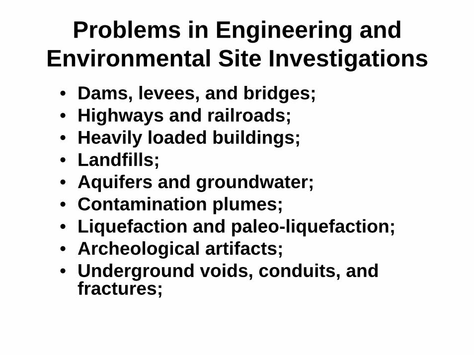
Problems in Engineering and Environmental Site Investigations
• Dams, levees, and bridges;• Highways and railroads;• Heavily loaded buildings;• Landfills;• Aquifers and groundwater;• Contamination plumes;• Liquefaction and paleo-liquefaction;• Archeological artifacts;• Underground voids, conduits, and
fractures;
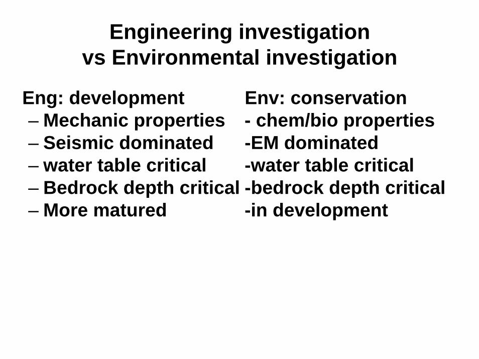
Engineering investigationvs Environmental investigation
Eng: development Env: conservation– Mechanic properties - chem/bio properties– Seismic dominated -EM dominated– water table critical -water table critical– Bedrock depth critical -bedrock depth critical– More matured -in development
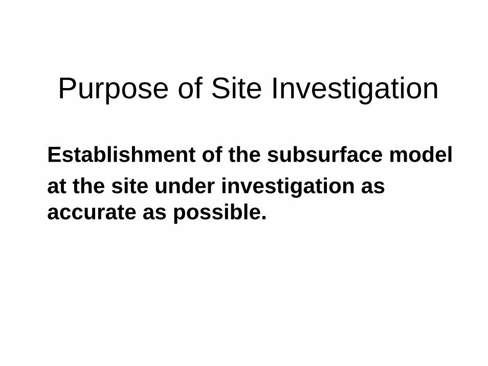
Purpose of Site Investigation
Establishment of the subsurface model at the site under investigation as accurate as possible.

3 Steps in Site Investigation
• 3-step approach: 1. Literature review, do your homework;2. Site visit and reconnaissance;3. Subsurface exploration:– direct and invasive techniques (boring
and coring);– Indirect and non-invasive techniques
(geophysical surveys,G228, G277).

1. Literature review• Review of designing plans and preliminary
plans:– How much is the impact (load, stress, demands)?
How deep it will go of the foundation?• Review of engineering reports:
– Reports of previous projects on the same site;– Reports of previous projects with similar nature of
the proposed one;– Review of public information or USGS open file
reports.


New tools for literature search
• World wide web (WWW)– Example 1: google earth– Example 2: site map:
http://terraserver.microsoft.com

2. Field reconnaissance• Visit the site by a group of experts:
– Project manager;– Designer;– Project geologist;– Project engineer;– Construction inspection personnel;– Town zoning officer.
• Purposes of Field reconnaissance: – To allow an experienced observer to view the site and
record information;– Preparing subsurface exploration (step 3);

2. Field reconnaissance (cont.): What to observe?
• Proposed location of the structure;• Topography and vegetation;• Surface soils, gullying (ditches and
trenches), and natural slopes;• Surface and subsurface water;• Surface and subsurface geology.

3. Subsurface exploration
– First need to run indirect and non-invasive techniques (geophysical surveys). This procedure can also provide more information for direct exploration;
– direct and invasive techniques (boring and coring, and other excavations).
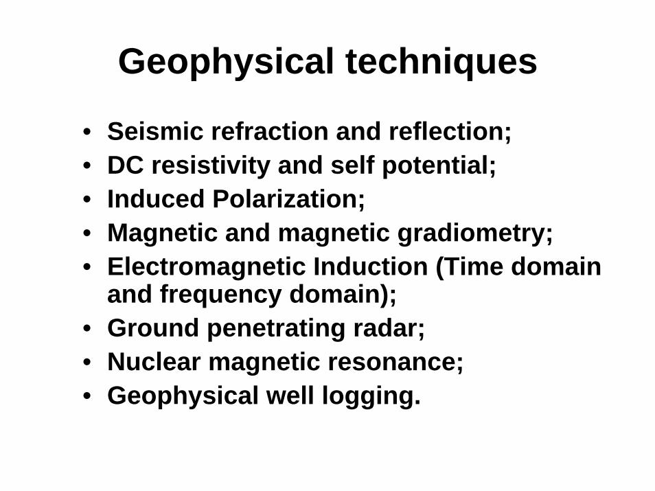
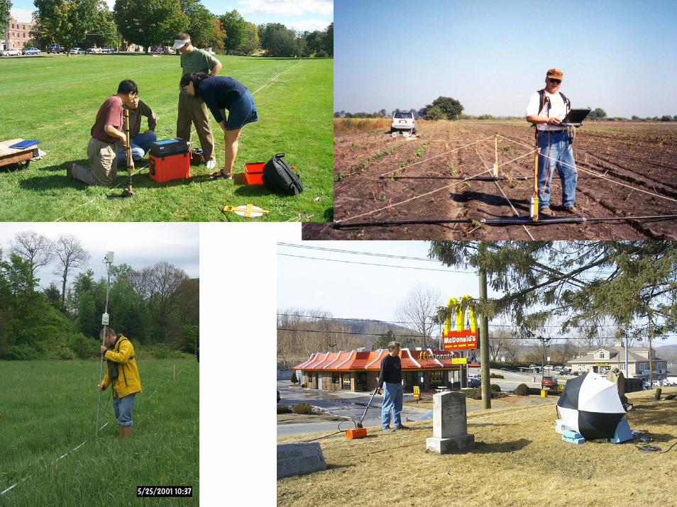
Geophysical techniques
• Seismic refraction and reflection;• DC resistivity and self potential;• Induced Polarization;• Magnetic and magnetic gradiometry;• Electromagnetic Induction (Time domain
and frequency domain);• Ground penetrating radar;• Nuclear magnetic resonance;• Geophysical well logging.
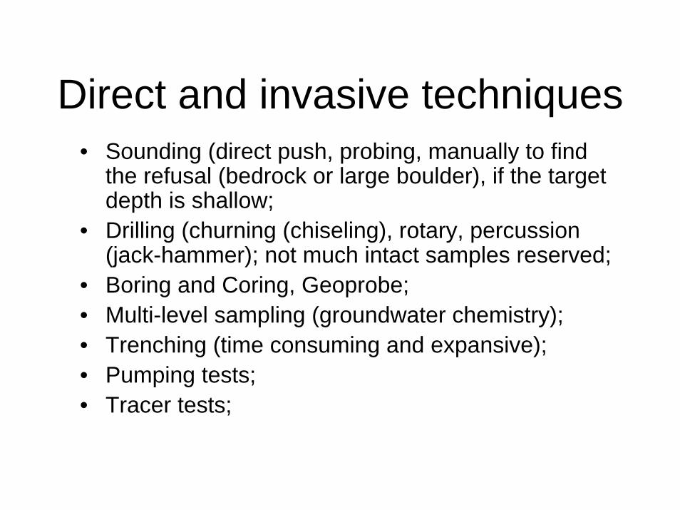
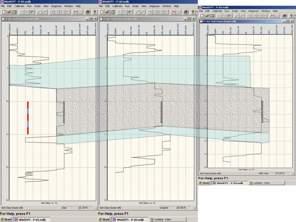
Direct and invasive techniques• Sounding (direct push, probing, manually to find
the refusal (bedrock or large boulder), if the target depth is shallow;
• Drilling (churning (chiseling), rotary, percussion (jack-hammer); not much intact samples reserved;
• Boring and Coring, Geoprobe;• Multi-level sampling (groundwater chemistry);• Trenching (time consuming and expansive);• Pumping tests;• Tracer tests;
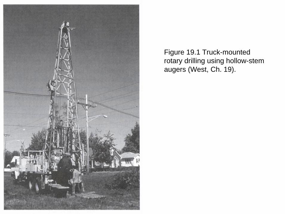
Figure 19.1 Truck-mounted rotary drilling using hollow-stem augers (West, Ch. 19).
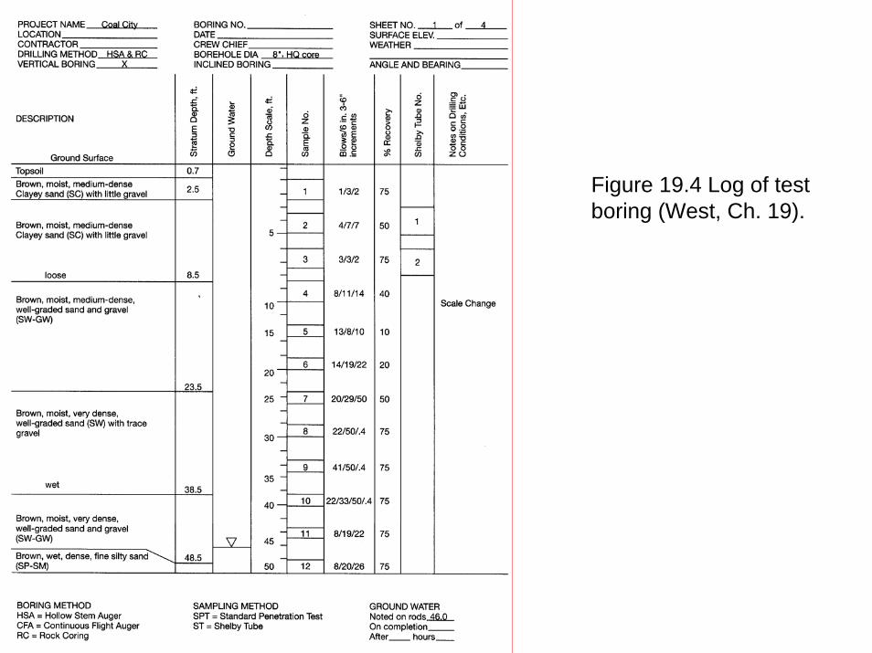
Figure 19.4 Log of test boring (West, Ch. 19).
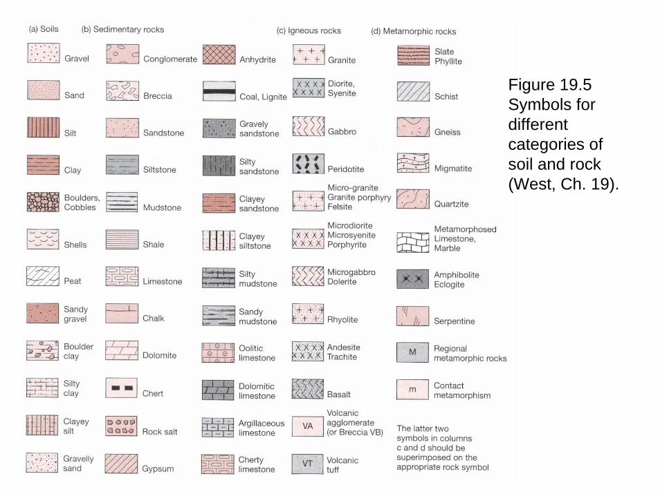
Figure 19.5 Symbols for different categories of soil and rock (West, Ch. 19).

Economical considerations
• Most site investigations are carried out by contractors in private sector industrial firms: money and time are the major constraints.
• Doing site investigation is doing business: – maximize the profit, minimize the expenses,
here the profit is the acquisition of information, as accurate as possible, with the least expense of monetary and man power consumptions.
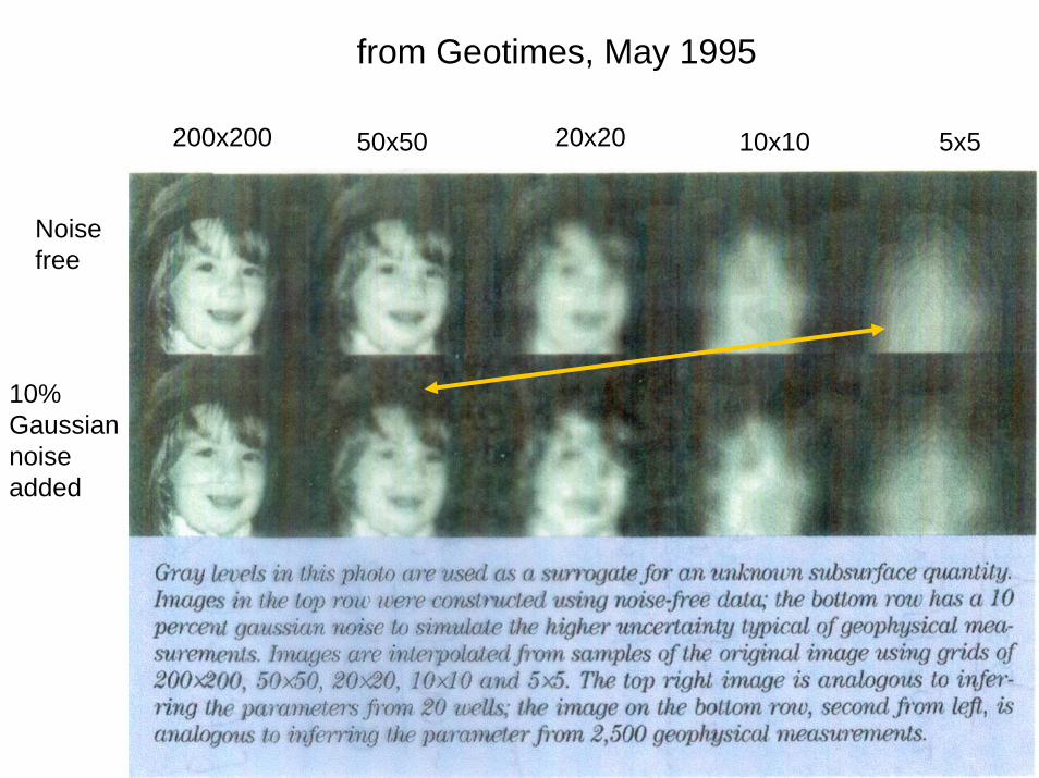
from Geotimes, May 1995
200x200 20x2050x50 10x10 5x5
Noise free
10% Gaussian noise added

Extrapolation from known to unknown:
• GPR survey at a cemetery site in New Milford, CT.


Choose the right tools: GPR vs Magnetic surveys
• There is not a tool universally working for all the engineering and environmental site investigation problems;
• The most expensive tool may not be the one you need for a particular site problem;
• Not New London, CT
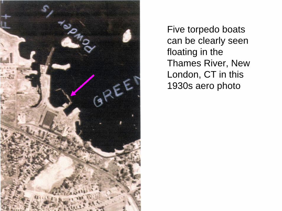
Five torpedo boats can be clearly seen floating in the Thames River, New London, CT in this 1930s aero photo


Complementary surveys: Seismic refraction and GPR
• Mansfield town hall, CT
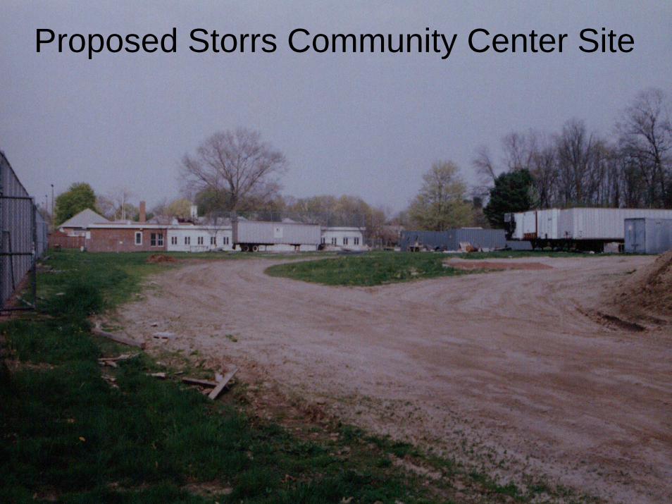
Proposed Storrs Community Center Site

Seismic Refraction ResultsProfile Parallel to the Tennis Courts
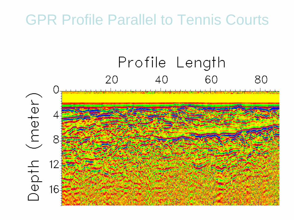
GPR Profile Parallel to Tennis Courts

GPR Profile Normal to Tennis Courts

Combination of direct/indirect methods:
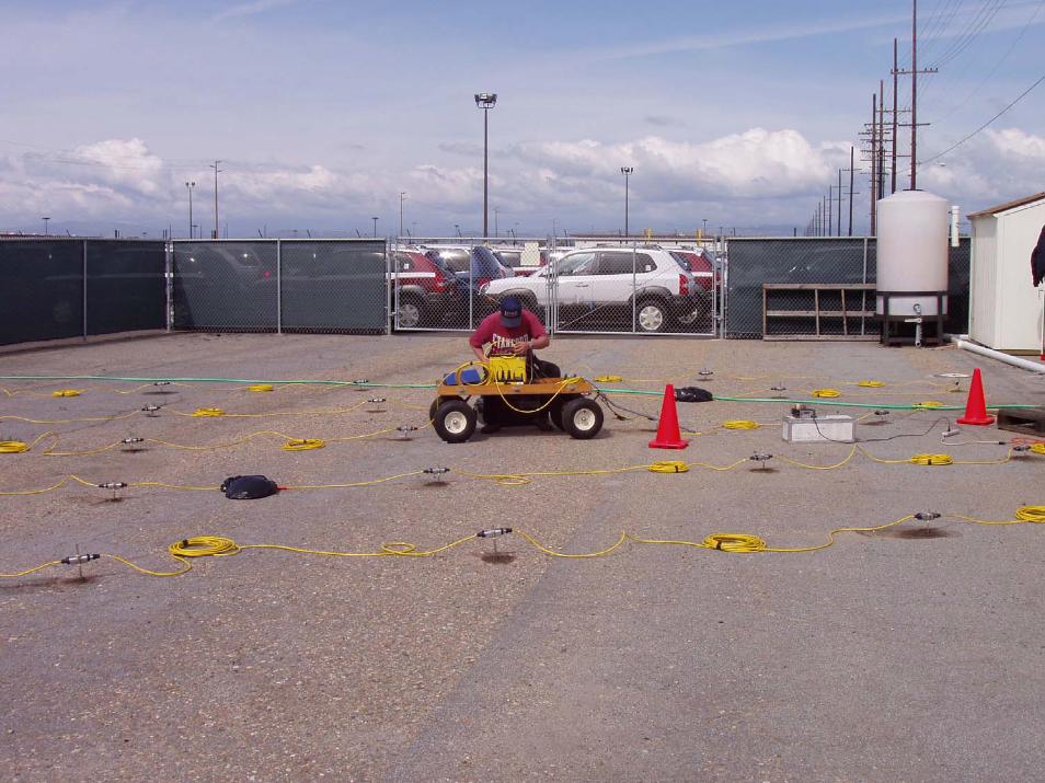
DC resistivity monitoring tracer test
• SEABEE Headquarter, CA

Utility PoleUtilityShed
WaterStorageTanks
20’V
ehic
leG
ate
20’V
ehic
leG
ate
4 ’Pe
rson
nel
Gat
e100’
60’
W1(Inject)
W3
W2
Utility PoleUtilityShed
WaterStorageTanks
20’V
ehic
leG
ate
20’V
ehic
leG
ate
4 ’Pe
rson
nel
Gat
e100’100’
60’
W1(Inject)
W3
W2
N
Note: Layout displayed with 10 ’ x 10’ grid
NN
Note: Layout displayed with 10 ’ x 10’ grid
N
Electrode locations for DC resistivity Surveys
East of Building 401East of Building 401Lot
AGI
1
2
3
4
56
7
8
9
10
1112
13
14
15
16
1718
19
20
21
22
23
24
25
26
27
28
Wells from previous extraction systemHydraulic Test WellsWells from previous extraction systemHydraulic Test WellsWells from previous extraction systemHydraulic Test WellsProposed electrode location


Utility PoleUtilityShed
WaterStorageTanks
20’V
ehic
leG
ate
20’V
ehic
leG
ate
4 ’Pe
rson
nel
Gat
e100’
60’
W1(Inject)
W3
W2
Utility PoleUtilityShed
WaterStorageTanks
20’V
ehic
leG
ate
20’V
ehic
leG
ate
4 ’Pe
rson
nel
Gat
e100’100’
60’
W1(Inject)
W3
W2
N
Note: Layout displayed with 10 ’ x 10’ grid
NN
Note: Layout displayed with 10 ’ x 10’ grid
N
Electrode locations for DC resistivity Surveys
East of Building 401East of Building 401Lot
AGI
1
2
3
4
56
7
8
9
10
1112
13
14
15
16
1718
19
20
21
22
23
24
25
26
27
28
Wells from previous extraction systemHydraulic Test WellsWells from previous extraction systemHydraulic Test WellsWells from previous extraction systemHydraulic Test WellsProposed electrode location


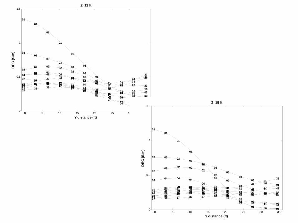
Day 00Day 01Day 02Day 03Day 04Day 07Day 11Day 16Day 23Day 31Day 37Day 41
0 5 10 15 20 25 30 350
0.5
1
1.5
00 00 00 0000
0000
00 00 00 00
0101
01
01
01
01
01
01
0101
01
0202 02 02
02
02
02
0202
02 02
0303
0303
03
03
03
0303 03 03
04 04 04 0404
04
04
04
0404
04
0707 07 07
0707
0707
07 07 07
1111 11 11 11
1111
1111 11 11
16 16 16 1616
1616 16 16 16
16
2323
23 23 2323 23 23 23 23 23
31 31 31 31 31 31 31 3131
313137 37
3737
3737 37
3737
373741 41 41 41
4141 41 41 41
4141
Y distance (ft)
DEC
(S/m
)
Z=12 ft
0 5 10 15 20 25 30 350
0.5
1
1.5
00 00 00 00 0000
00 00 00 00 00
0101
01
01
01
01
01
0101 01 01
0202 02 02
0202
02
0202
0202
03 03 0303
0303
0303
0303 03
04 04 04 0404
04
04
0404 04 04
07 07 07 07 0707
0707
07 07 07
1111 11 11 11
1111
1111 11 11
16 16 16 16 16 16 16 16 16 16 1623
2323 23 23 23 23 23 23 23 23
3131
31 31 31 31 31 3131
3131
37 37 37 37 37 37 3737
3737
37
4141
41 41 41 41 41 41 41 41 41
Y distance (ft)
DEC
(S/m
)
Z=15 ft

Use Multiple Surveys to Synergize the most comprehensive model
• Case example:– UConn’s Willimantic River Wellfield– GPR, Resistivity, Seismic refraction
tomography

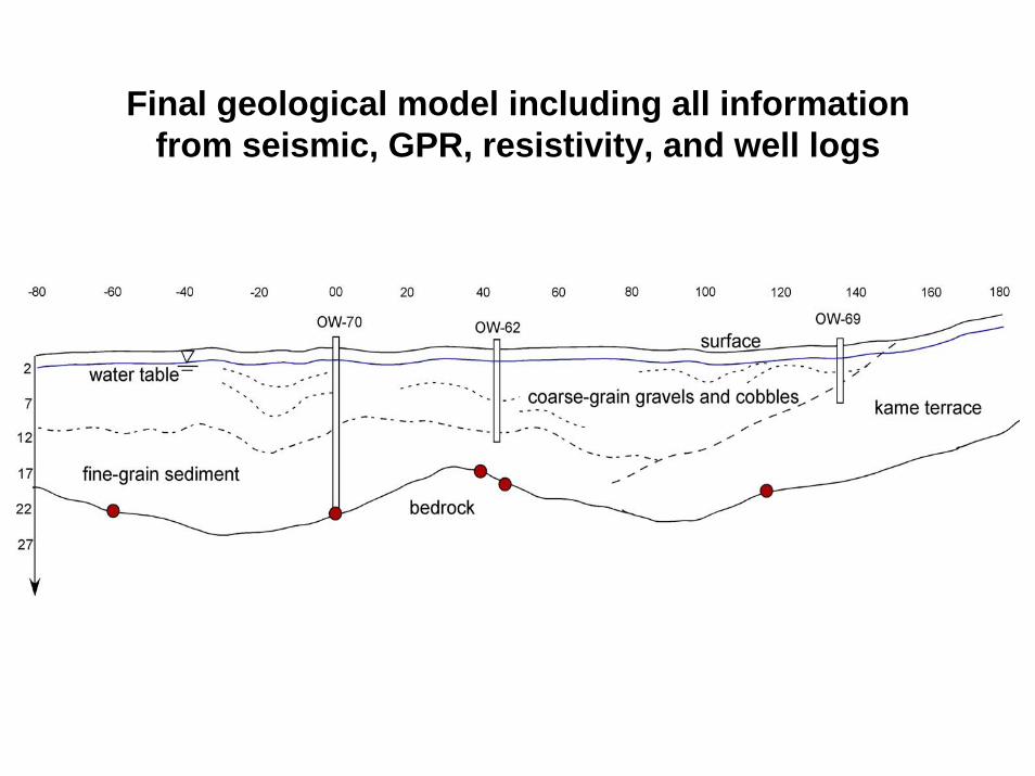
Final geological model including all information from seismic, GPR, resistivity, and well logs