generator set manual - design dlathe prime mover is a continuous duty, highly modified avco lycoming...
TRANSCRIPT

Generator SetManual

AEP Gas Power Systems
Innovator Generator Set
(Picture from Corp. Comm.)
Manual
July 2001 The information in this publication is subject to change and product improvement. Copies of this and other publications can be obtained through the General Services’ Documentation Solutions department, a part of Office Services. Address comments to:
Documentation Solutions P.O. Box 201 Tulsa, Oklahoma 74102-0201 (918) 599-2875
Copyright © 2001 AEP Gas Power Systems LLC No claim to copyright is made for the material contained in Appendix B and C. AEP Gas Power Systems Innovator Generator Set Manual, version 0 No part of this publication may be reproduced in any form or by any means without written permission from AEP Gas Power Systems.

AEP Gas Power Systems Contents • i
Contents Product Overview ........................................................................................................................... 1
Overview..................................................................................................................................... 1 Innovator Diagram...................................................................................................................... 3 Engine ......................................................................................................................................... 5 Gearbox....................................................................................................................................... 7 Generator..................................................................................................................................... 8 Control System............................................................................................................................ 9 Innovator Features and Spec Sheet ........................................................................................... 10
Installation..................................................................................................................................... 15 Overview................................................................................................................................... 15 Safety Considerations ............................................................................................................... 16 Site Preparation......................................................................................................................... 17 Receiving and Handling............................................................................................................ 18 Inspection.................................................................................................................................. 20 Pre-Installation Equipment ....................................................................................................... 21 Minimum Requirements ........................................................................................................... 22 Installation Detail...................................................................................................................... 27 Generator Storage and Preservation.......................................................................................... 30 Generator Storage and Preservation.......................................................................................... 30 Computer System...................................................................................................................... 31
Operation and Daily Maintenance ................................................................................................ 33 Overview................................................................................................................................... 33 Initial Start Check List .............................................................................................................. 35 Daily Running Check List ........................................................................................................ 38 Weekly Running Check List..................................................................................................... 41 30-Day Restart and Monthly Running Check List ................................................................... 42 How to Start Generator ............................................................................................................. 43 Post-Run Check (Shut Down)................................................................................................... 44 Emergency Shut Down ............................................................................................................. 45 Computer Operation.................................................................................................................. 46
Maintenance.................................................................................................................................. 49 Overview................................................................................................................................... 49 Oil System................................................................................................................................. 50 Fuel System............................................................................................................................... 57 Air System ................................................................................................................................ 59 Battery Maintenance ................................................................................................................. 60 Engine Compressor Section...................................................................................................... 63 Major Maintenance Schedule ................................................................................................... 64 Heavy Maintenance .................................................................................................................. 65
Maintenance Parts......................................................................................................................... 67 Recommended Parts List .......................................................................................................... 67
Troubleshooting ............................................................................................................................ 69 General Topics .......................................................................................................................... 69

ii • Contents AEP Gas Power Systems
Appendix A................................................................................................................................... 75
Manufacturer Information List ................................................................................................. 75 Appendix B ................................................................................................................................... 77
Manufacturer Reference Manuals............................................................................................. 77 Appendix C ................................................................................................................................... 79
Material Safety Data Sheets...................................................................................................... 79 Appendix D................................................................................................................................... 81
Drawings ................................................................................................................................... 81

AEP Gas Power Systems Preface • iii
Preface
Notices This manual outlines procedures for operating and maintaining the Innovator generator set using safe, effective methods. The procedures contain Notes, Cautions and Warnings, which should be followed, along
with standard procedures to eliminate the possibility of personal injury or improper service, which could damage the unit.
Although information in this manual is as complete as possible during the time of publication, the possibility exists that some information may not be current.
AEP Gas Power Systems cannot assume the responsibility for any errors, changes or omissions that may occur in the compilation of this information.
Safety Precautions
WARNING
The use of electric machinery can be hazardous. Installation, maintenance, and operation should be performed by qualified personnel; while adhering to all local, state and federal codes including, but not limited to, the National Electrical Code.
For equipment covered in this manual, it is important to observe safety precautions to eliminate the possibility of personal injury and/or damage to the equipment. Among many considerations are the following:
• Avoid high temperature exhaust.
• Shutoff fuel/lockout before performing maintenance.
• Avoid rotating shafts and do not wear loose clothing in proximity of rotating machinery.
• Perform all maintenance in accordance with owner’s lockout/clearance procedures and safety policies.
• Wear hearing protection proximity of this equipment while in operation. See OSHA standard 1910.95 available at www.osha.gov.
• Do not install or operate unit near flammable liquid or materials storage and accumulations of trash or debris should be kept away from unit.
These instructions do not purport to cover all details for variations in equipment or to provide for every possible contingency to be met in connection with installation, operation, or maintenance. Should further information be desired or should particular problems arise which are not covered sufficiently for the purchaser’s purposes, the matter should be referred to American Electric Power Gas Power Systems, P.O. Box 1623, Columbus, Ohio 43216-1623

AEP Gas Power Systems Overview • 1
Product Overview Overview
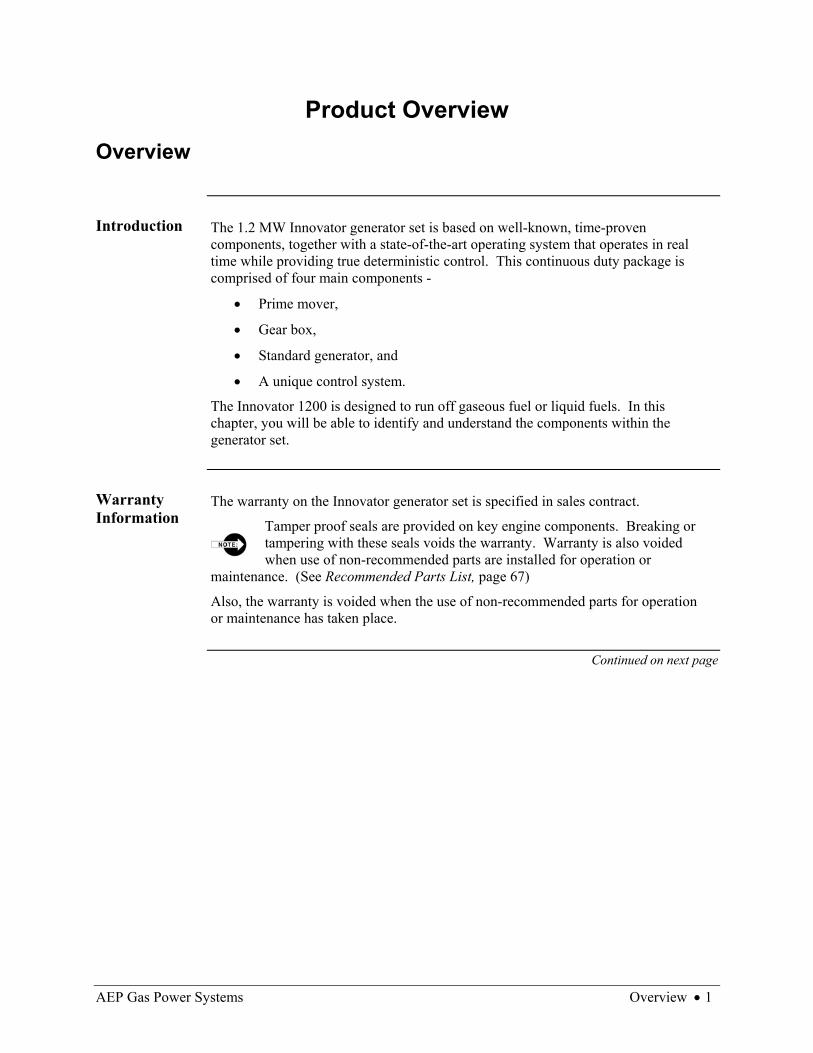
Introduction The 1.2 MW Innovator generator set is based on well-known, time-proven
components, together with a state-of-the-art operating system that operates in real time while providing true deterministic control. This continuous duty package is comprised of four main components -
• Prime mover,
• Gear box,
• Standard generator, and
• A unique control system.
The Innovator 1200 is designed to run off gaseous fuel or liquid fuels. In this chapter, you will be able to identify and understand the components within the generator set.
Warranty Information
The warranty on the Innovator generator set is specified in sales contract.
Tamper proof seals are provided on key engine components. Breaking or tampering with these seals voids the warranty. Warranty is also voided when use of non-recommended parts are installed for operation or
maintenance. (See Recommended Parts List, page 67)
Also, the warranty is voided when the use of non-recommended parts for operation or maintenance has taken place.
Continued on next page
2 • Overview AEP Gas Power Systems
Overview, Continued
In This Chapter
This chapter contains the following topics:
Topic See Page Innovator Diagram 3 Engine 5 Gearbox 7 Generator 8 Control System 9 Innovator Features and Spec Sheet 10

AEP Gas Power Systems Innovator Diagram • 3
Innovator Diagram
Part Identification
The photos below identify components from both long-side views of the Innovator.
Figure 1, Long-side Front
Figure 2, Long-side Back
Continued on next page
12
3 46
75
76
5
9
12
8
1011 12
8
1314
15
16
4 • Innovator Diagram AEP Gas Power Systems
Innovator Diagram, Continued
Part Identification Legend
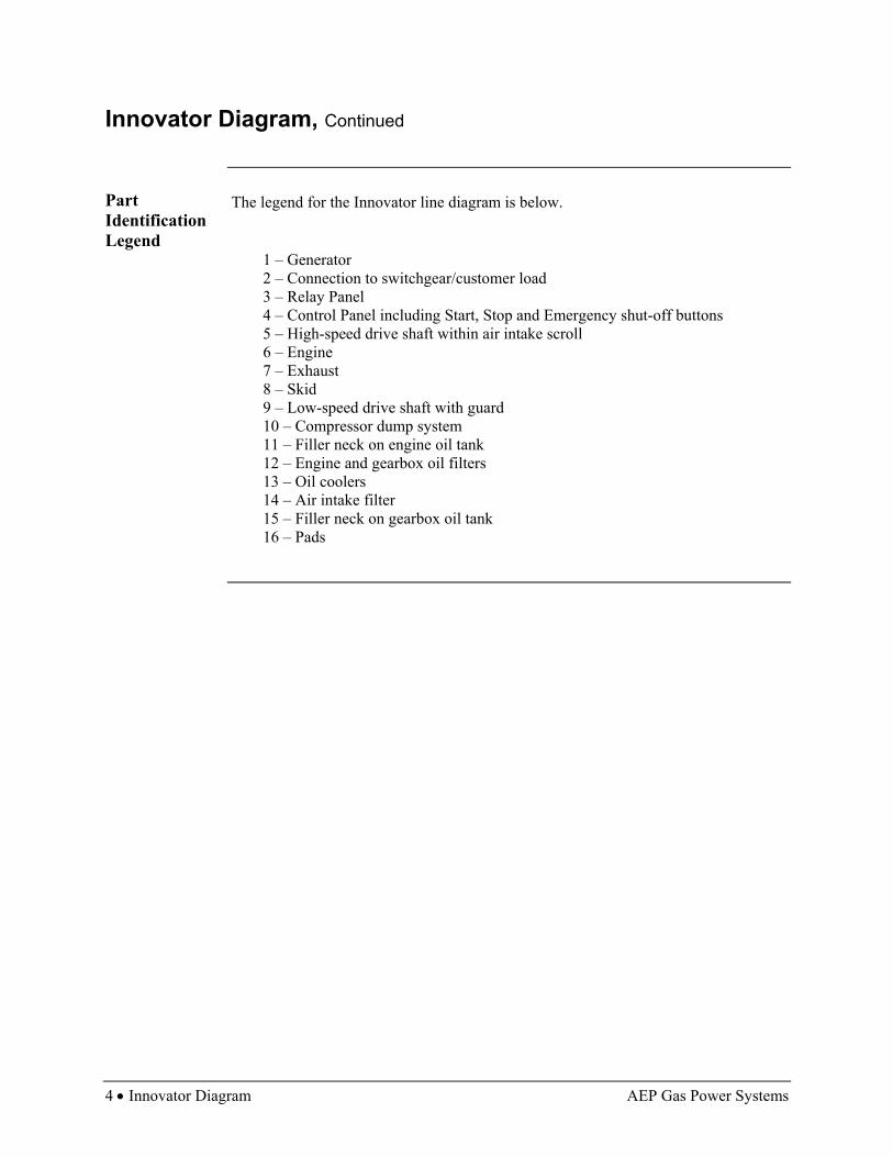
The legend for the Innovator line diagram is below.
1 – Generator 2 – Connection to switchgear/customer load 3 – Relay Panel 4 – Control Panel including Start, Stop and Emergency shut-off buttons 5 – High-speed drive shaft within air intake scroll 6 – Engine 7 – Exhaust 8 – Skid 9 – Low-speed drive shaft with guard 10 – Compressor dump system 11 – Filler neck on engine oil tank 12 – Engine and gearbox oil filters 13 – Oil coolers 14 – Air intake filter 15 – Filler neck on gearbox oil tank 16 – Pads

AEP Gas Power Systems Engine • 5
Engine
About the Engine
The prime mover is a continuous duty, highly modified Avco Lycoming T53 Gas Turbine Engine. This aero-derivative engine has an impressive 40 million hour history of excellent performance and reliability. The engine has been modified to stringent AEP GPS specifications to accommodate multiple industrial applications requiring 1,400 +SHP at a variety of output shaft speeds up to 21,000 RPM. Its features are as follows:
• Split-shaft design with five-stage axial compressor • One-stage centrifugal compressor • Two-stage gas producer turbine • Two-stage power turbine with onboard reduction gearing • Output speed of 6,000 RPM • Output up to 1,200 kW
Image Below is a photograph of the engine.
Figure 3, Engine
Continued on next page
Exhaust area will have high temperatures and airflow.

6 • Engine AEP Gas Power Systems
Engine, Continued
Sub-Systems There are four sub-systems associated with the engine component of the generator
set which are identified and described in the table below.
Sub-System Detail Lubrication System (engine only)
• Requires 28 gallons of MIL-L-23699 Aeroshell 500 oil • Oil pressure is set at 60-80 psi at 150°F or 65°C • Pressure lube through a motor-driven gear pump with gravity
return Cooling System
• Closed-loop system • Maximum engine inlet temperature of 200°F or 93°C • 3 micron absolute spin-on oil filter • Motor driven, temperature actuated, computer-controlled gear-
pump • Cooling radiator with motor-driven forced air fan
Fuel (gas) System
• Customer supplied, 150 psi combustible gas • Paper element, high-pressure gas filter • Normally-closed emergency solenoid valve • Computer-controlled fuel valve supplying four lines; two lines
go to each of the two manifolds • Each manifold contains 11 fuel distribution nozzles
Ignition System
• Computer-controlled capacitor discharge • Four combustion chamber mounted spark igniters

AEP Gas Power Systems Gearbox • 7
Gearbox
About the Gearbox
Cotta Transmission Company developed the reduction gearbox. This gearbox was specifically designed and manufactured to produce either an 1,800 RPM or 1,500 RPM output to the generator. Its characteristics are identified below:
• Two gear pressure lube gravity return • 3.32 to 1 reduction gearing assembly • All main bearings have temperature sensors
Image Below is a picture of the gearbox.
Figure 4, Gearbox
Sub-Systems There are two sub-systems associated with the gearbox component of the generator
set which are identified and described in the table below.
Sub-System Detail Lubrication System (gearbox only)
• Requires 14 gallons of MIL-L-23699 turbine oil • Oil pressure is set at 20-25 psi at 100°F or 38°C • Motor driven, positive displacement gear pump
Cooling System (same as engine cooling system)
• Maximum gearbox inlet temperature of 150°F or 65°C • 3 micron absolute spin-on oil filter • Motor driven, temperature actuated, computer-controlled gear-
pump • Cooling radiator with motor-driven forced air fan • Closed-loop system

8 • Generator AEP Gas Power Systems
Generator
About the Generator
The generator is built by Newage International Limited and is designed for easy installation, minimum operating vibration and rapid response to widely varying electrical loads. The generator consists of the following characteristics:
• 1,500 RPM (50Hz) or 1,800 RPM (60Hz) 4-pole generator • On-board voltage control regulator • On-board bearing temperature sensors and stator winding temperature
sensors • Two-bearing generator • Synchronous generator • Wye configuration • 1500 MVA, 80% power factor
Image Below is a picture of the generator.
Figure 5, Generator
Sub-Systems There are two sub-systems associated with the generator component of the generator
set which are identified and described in the table below.
Sub-System Detail Lubrication System
• Sealed bearings or grease fitting bearings, depending on unit provided
Cooling System • On-board generator driven suction fan

AEP Gas Power Systems Control System • 9
Control System
About the Control System
The Innovator Control System is an advanced and highly reliable feature. The Innovator control was developed by AEP GPS engineers in cooperation with OMNX Direct Control, a division of Olin Corporation. It offers a direct connection between the I/O and processor eliminating relays, timers and PLCs. The signals are processed at speeds up to 1ms update rate providing speed and stability surpassing traditional control systems.
The Control System has a Man Machine Interface (MMI) with graphics help and information. The input/output interface is a Computer Machine Interface (CMI). The Control System features are described below.
• PC-based, multi Input/Output, multi-function real-time direct control system • 2 analog outputs control fuel valves and linear actuators • 30 analog inputs control pressure speed and temperature • 14 digital outputs control various relay functions • 4 digital inputs sense activation of remote relays • PC included on generator unit • Outputs available for monitor, keyboard and mouse • Remote monitoring capabilities using networking or telecommunications
Image Below is a picture of one screen of the control system.
Figure 6, Screen of Control System
10 • Innovator Features and Spec Sheet AEP Gas Power Systems
Innovator Features and Spec Sheet
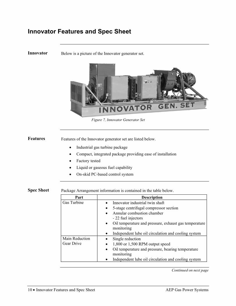
Innovator Below is a picture of the Innovator generator set.
Figure 7, Innovator Generator Set
Features Features of the Innovator generator set are listed below.
• Industrial gas turbine package • Compact, integrated package providing ease of installation • Factory tested • Liquid or gaseous fuel capability • On-skid PC-based control system
Spec Sheet Package Arrangement information is contained in the table below.
Part Description Gas Turbine • Innovator industrial twin shaft
• 5-stage centrifugal compressor section • Annular combustion chamber
- 22 fuel injectors • Oil temperature and pressure, exhaust gas temperature
monitoring • Independent lube oil circulation and cooling system
Main Reduction Gear Drive
• Single reduction • 1,800 or 1,500 RPM output speed • Oil temperature and pressure, bearing temperature
monitoring • Independent lube oil circulation and cooling system
Continued on next page

AEP Gas Power Systems Innovator Features and Spec Sheet • 11
Innovator Features and Spec Sheet, Continued
Spec Sheet (continued)
Part Description Generator • 1500 MVA, 80% power factor
• Salient pole, 3-phase, 6-wire, wye connected, synchronous with brushless exciter
• Open drip-proof construction • Ball bearings • Solid state voltage regulation with permanent magnet
generator • NEMA Class H insulation with H Rise • Continuous duty rating • Phase winding temperature and bearing temperature
monitoring Package • Steel base with drip pans
• Direct drive DC starter • Natural gas fuel system
Control System • PC based • Generator control • Pressure and temperature monitoring
Gas Turbine Engine and Gearbox Lube Oil Systems
• DC electric drive lube oil pumps • DC electric drive post lube oil pumps • Individual engine and gearbox air/oil coolers • Individual engine and gearbox air/oil tanks • Spin-on lube oil filters
Lube Oil Demisting System
• Mechanical demister placed on the engine oil tank vent
Documentation • Operation and maintenance manuals • Drawings • Maintenance schedule • Operational check sheets • Test reports
Fuel Consumption • Approximately 374 mscf per day of natural gas at full load
Continued on next page

12 • Innovator Features and Spec Sheet AEP Gas Power Systems
Innovator Features and Spec Sheet, Continued
Spec Sheet (continued)
Part Description Full Load Factory Testing of Gas Turbine and Package
• Each unit will be tested prior to shipment • Reports will be included with unit
Auxiliary Power The skid’s auxiliary components (oil, pumps, cooling fans, controls, starters, etc.) are powered by a 24-volt DC power system. On-board batteries supply the power for starting and operating the generator set, but by themselves cannot sustain operation of the generator set. Power to maintain the battery’s charge and sustain the operation of the generator set can be provided by the following:
• A 24-volt DC engine powered auxiliary power unit • An AC house powered rectified 24-volt DC battery
maintaining/charging system • An on-board optional belt driven alternator providing
black start (see below) capability. The skid is provided with 24-volt DC motors on oil pumps, fans and starters. As an option, AC motors can be supplied if AC power is available from an
external source. Black Start Black start is defined as having the optional installed
components that allow the generator set to start and operate with no external power available. The black start components consist of a skid mounted, belt driven 375 amps 28.8-volt DC alternator. This alternator is capable of providing power to operate the generator set’s 24-volt DC auxiliary components and controls, as well as recharge the starting batteries. For black start capability, a 150 psi high pressure gas source is required.
Continued on next page

AEP Gas Power Systems Innovator Features and Spec Sheet • 13
Innovator Features and Spec Sheet, Continued
Nominal Performance Ratings
The Nominal Performance Ratings are listed in the table below.
No inlet or exhaust loss; ISO conditions, pipeline natural gas fuel with LHV+31.5 to 43.3 MJ/nm3 (800-1100 BTU/scf)
Category Nominal Performance Rating Output Power kWe ISO: 15 degrees °C (59°F), sea level
1,200
Heat Rate, kJ/kWe-hr (BTU/kWe-hr)
14227 (13,485)
Exhaust Flow kg/hr (lb/hr) Exhaust Temperature, °C (°F)
18,897 (41,700) 578 (1,072)
Fuel Consumption (mscf) 374
Optional Equipment and Services
The Optional Equipment and Services available are in the table below.
Part Description Generator Options • Standard duty rating
• Standard voltages: 330, 3,300 at 50 Hz; 480, 4,160 at 60 Hz
Fuel Systems • Liquid (such as diesel and #2 fuel oil) • Alternate fuels (such as naptha, propane, and low
BTU methane) Lube Oil System • Water/oil lube oil cooler
• Electrostatic demister • Lube oil tank heater
Control System • Remote display/control terminal • Heat recovery application interface • Remote supervisory interface kW control • KVAR/power factor control • Vibration monitoring
Accessory Equipment
• Turbine cleaning system: on-crank and on-line • Package lifting kit
Enclosure • Optional weatherproof /acoustic enclosure
Continued on next page

14 • Innovator Features and Spec Sheet AEP Gas Power Systems
Innovator Features and Spec Sheet, Continued
Optional Equipment and Services (continued)
Part Description Ancillary Equipment: Various Air Inlet and Exhaust Systems
• Inlet and exhaust silencers • Self-cleaning or prefilter/barrier inlet filter • Inlet evaporative cooler • Exhaust gas SCR clean-up system
Switchgear • Independent operation • Parallel operation
All switchgear must meet the appropriate federal, state and local requirements; for example, the National Electric Code (United States).

AEP Gas Power Systems Overview • 15
Installation Overview
Introduction
Install the generator in accordance with the National Electrical Code and consistent with sound practices and all legal codes.
Installation requirements for the Innovator generator set are site specific. For example, the installation may be permanent, temporary, emergency or portable. After reading this chapter, you will understand several safety concerns, site preparation, receiving and handling, and all customer pre-installation and AEP GPS pre-installation requirements.
The customer is responsible for adhering to all federal, state and local codes.
In This Chapter
This chapter contains the following topics:
Topic See Page Safety Considerations 16 Site Preparation 17 Receiving and Handling 18 Inspection 20 Pre-Installation Equipment 21 Minimum Requirements 22 Installation Detail 27 Generator Storage and Preservation 30 Computer System 31
16 • Safety Considerations AEP Gas Power Systems
Safety Considerations
Overview
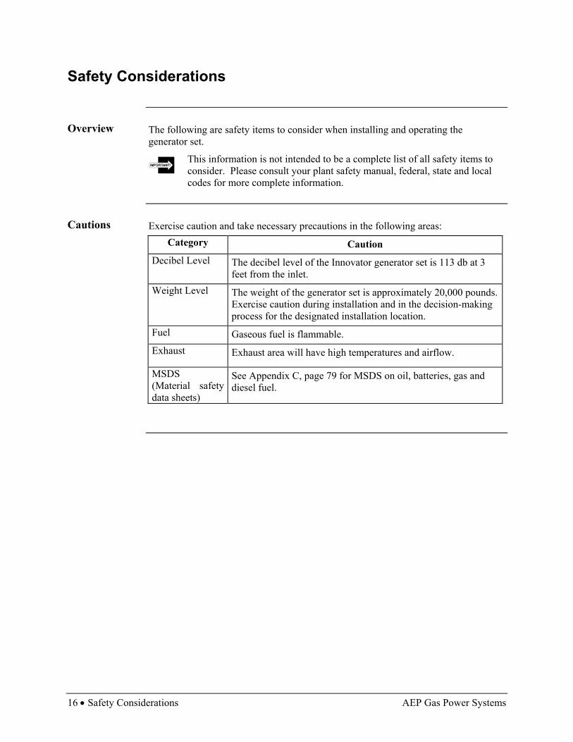
The following are safety items to consider when installing and operating the generator set.
This information is not intended to be a complete list of all safety items to consider. Please consult your plant safety manual, federal, state and local codes for more complete information.
Cautions Exercise caution and take necessary precautions in the following areas:
Category Caution Decibel Level The decibel level of the Innovator generator set is 113 db at 3
feet from the inlet. Weight Level The weight of the generator set is approximately 20,000 pounds.
Exercise caution during installation and in the decision-making process for the designated installation location.
Fuel Gaseous fuel is flammable. Exhaust Exhaust area will have high temperatures and airflow.
MSDS (Material safety data sheets)
See Appendix C, page 79 for MSDS on oil, batteries, gas and diesel fuel.

AEP Gas Power Systems Site Preparation • 17
Site Preparation
Requirements Meet the following requirements before installing the generator set.
• Prepare a clear, level area • Position unit so prevailing winds are on long side of unit container, not at
either end of unit • Place generator set unit in proximity to grid power connections (if
applicable) • Clear exhaust area • Cover ground with gravel and seal for dust control • Set unit on level piers, foundation or a pad capable of withstanding 14,620
pounds for bare skid or 20,000 pounds for enclosed unit • Install security fence surrounding unit within local, state and federal codes • Maintain the appropriate distance surrounding the unit for noise abatement
within local, state and federal codes • Install in a location that can be kept clean and free of blowing dust, dirt and
trash • Keep location isolated from vibration sources especially near 1,800 RPM
Floor Loading The area that the skid is place upon shall be capable of supporting 200 lb/in2.
Support Points
The skid is designed to rest on four load pads to properly support the unit and provide correct alignment of the equipment on the skid. There shall be no support rather than that of the pads.
Weights The overall dimension of the generator set is 17 feet by 6 feet. The following table
identifies the weight of the unit and components.
Part Weight Gearbox 1,000 lb Generator 6,060 lb Skid and Engine Ring 3,500 lb Engine 650 lb Oil and Oil System 500 lb Misc. Electric and Mechanical Auxiliary Components 2,910 lb Total Weight 14, 620 lb
18 • Receiving and Handling AEP Gas Power Systems
Receiving and Handling
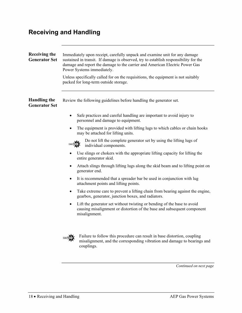
Receiving the Generator Set
Immediately upon receipt, carefully unpack and examine unit for any damage sustained in transit. If damage is observed, try to establish responsibility for the damage and report the damage to the carrier and American Electric Power Gas Power Systems immediately.
Unless specifically called for on the requisitions, the equipment is not suitably packed for long-term outside storage.
Handling the Generator Set
Review the following guidelines before handling the generator set.
• Safe practices and careful handling are important to avoid injury to personnel and damage to equipment.
• The equipment is provided with lifting lugs to which cables or chain hooks may be attached for lifting units.
Do not lift the complete generator set by using the lifting lugs of individual components.
• Use slings or chokers with the appropriate lifting capacity for lifting the entire generator skid.
• Attach slings through lifting lugs along the skid beam and to lifting point on generator end.
• It is recommended that a spreader bar be used in conjunction with lug attachment points and lifting points.
• Take extreme care to prevent a lifting chain from bearing against the engine, gearbox, generator, junction boxes, and radiators.
• Lift the generator set without twisting or bending of the base to avoid causing misalignment or distortion of the base and subsequent component misalignment.
Failure to follow this procedure can result in base distortion, coupling misalignment, and the corresponding vibration and damage to bearings and couplings.
Continued on next page
AEP Gas Power Systems Receiving and Handling • 19
Receiving and Handling, Continued
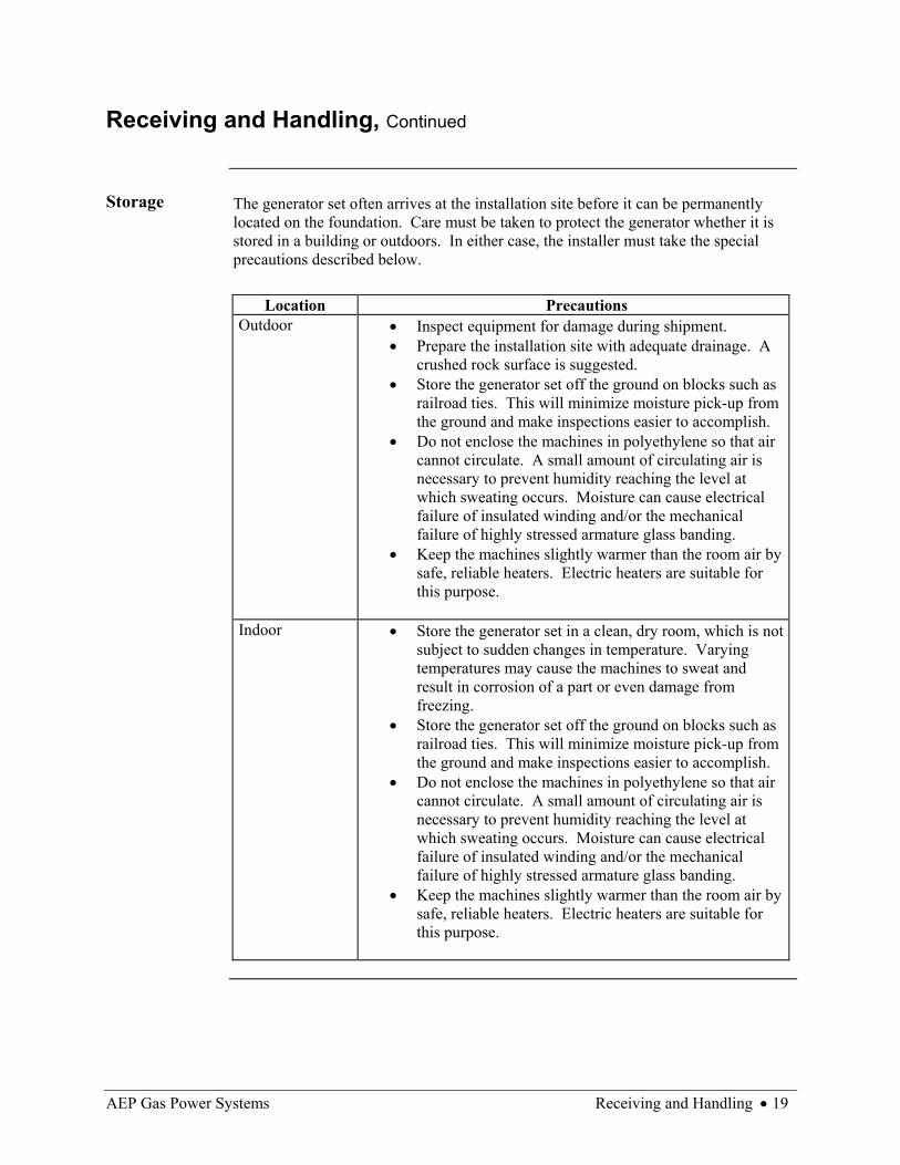
Storage The generator set often arrives at the installation site before it can be permanently
located on the foundation. Care must be taken to protect the generator whether it is stored in a building or outdoors. In either case, the installer must take the special precautions described below.
Location Precautions
Outdoor • Inspect equipment for damage during shipment. • Prepare the installation site with adequate drainage. A
crushed rock surface is suggested. • Store the generator set off the ground on blocks such as
railroad ties. This will minimize moisture pick-up from the ground and make inspections easier to accomplish.
• Do not enclose the machines in polyethylene so that air cannot circulate. A small amount of circulating air is necessary to prevent humidity reaching the level at which sweating occurs. Moisture can cause electrical failure of insulated winding and/or the mechanical failure of highly stressed armature glass banding.
• Keep the machines slightly warmer than the room air by safe, reliable heaters. Electric heaters are suitable for this purpose.
Indoor • Store the generator set in a clean, dry room, which is not
subject to sudden changes in temperature. Varying temperatures may cause the machines to sweat and result in corrosion of a part or even damage from freezing.
• Store the generator set off the ground on blocks such as railroad ties. This will minimize moisture pick-up from the ground and make inspections easier to accomplish.
• Do not enclose the machines in polyethylene so that air cannot circulate. A small amount of circulating air is necessary to prevent humidity reaching the level at which sweating occurs. Moisture can cause electrical failure of insulated winding and/or the mechanical failure of highly stressed armature glass banding.
• Keep the machines slightly warmer than the room air by safe, reliable heaters. Electric heaters are suitable for this purpose.

20 • Inspection AEP Gas Power Systems
Inspection
Prior to Installation
Carefully inspect the generator before installing generator set. Remove items listed below before installation:
• Any temporary protective coatings
• Any shipping covers and braces
During Installation
Carefully protect items listed below during installation to avoid damage from paint spray, weld splatter, welding rod butts, or metal chips from files and grinders, which could fall onto the generator.
• Bearings
• Terminal Box
• Windings
General Inspection
Follow inspection procedures before starting the machine for the first time, after an extended shut down, or after extensive maintenance or repair.
Be sure to check the following items:
• Check air passages to make sure they are free from all foreign objects, such as dirt, lint, old rags, wood chips, metal particles, or rodent nests
• If necessary, blow out the windings with clean dry air
• Inspect couplings for damage prior to operation and check all fasteners for tightness

AEP Gas Power Systems Pre-Installation Equipment • 21
Pre-Installation Equipment
Customer Supplied
The customer needs to meet the following requirements prior to installation of the generator set.
Equipment Detail Fuel Supply • Approved combustible gaseous system
• 150 psi at 16 million BTU’s per hour at maximum performance
Gas System • All piping/plumbing required as per local, state and federal codes
Interconnect Equipment
• All connection cables, switchgear and interconnect equipment as per local, state and federal codes
• The interconnection of the Control System to the switchgear must be tailored to the customer’s specific equipment
• When connecting the unit, carefully follow the instructions in the switchgear, paralleling unit if applicable, and this manual
Air Filtration • CFM based on site specifications Installation Equipment
• Appropriate forklift or crane
Fire Suppression • Appropriate fire suppression equipment is required when customer supplies unit container
AEP GPS Supplied
AEP Gas Power System will meet the following pre-installation requirements.
Equipment Detail Gas Filter • Supplied based on site specifications
• Customer (or customer’s contractor) must install gas filter based on manufacturer recommendations (See How to Change High Pressure Gas Filter, page 57)
Emergency Shut-Off
• Customer (or customer’s contractor) must install emergency shut-off in accordance with fuel source and Innovator generator set control valve within approved procedures
Initial Start-Up • An AEP GPS Field Technician can be made available to assist in a supervisory capacity during the initial start-up procedure
Fire Suppression • Appropriate fire suppression equipment will be provided when AEP GPS supplies the generator set in an enclosure
22 • Minimum Requirements AEP Gas Power Systems
Minimum Requirements
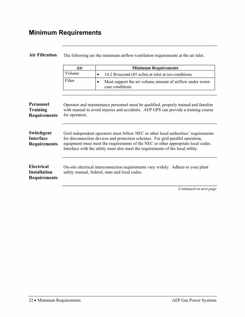
Air Filtration The following are the minimum airflow/ventilation requirements at the air inlet.
Air Minimum Requirements Volume • 14.2 lb/second (85 scfm) at inlet at iso-conditions Filter • Must support the air volume amount of airflow under worst-
case conditions
Personnel Training Requirements
Operator and maintenance personnel must be qualified, properly trained and familiar with manual to avoid injuries and accidents. AEP GPS can provide a training course for operators.
Switchgear Interface Requirements
Grid independent operators must follow NEC or other local authorities’ requirements for disconnection devices and protection schemes. For grid parallel operation, equipment must meet the requirements of the NEC or other appropriate local codes. Interface with the utility must also meet the requirements of the local utility.
Electrical Installation Requirements
On-site electrical interconnection requirements vary widely. Adhere to your plant safety manual, federal, state and local codes.
Continued on next page

AEP Gas Power Systems Minimum Requirements • 23
Minimum Requirements, Continued
Natural Gas Supply Piping Requirements
See figure and requirements below for Natural Gas Supply Piping.
Generator GearBox Engine
FuelControlValve
4 Flex hosesconnected tofuel manifold
GasFilter
Flange
3" pipe
EmergencyShut Off
Gas Source
Owner SuppliedHand Shut Off
Valve
Figure 8, Natural Gas Supply Piping
Label Requirements
Field Run According to location Source Either from high-pressure gas main with metering and regulators to
approximately 150 psig or from off-skid gas compressor with approximately 150 psig output pressure
Piping To be 3” Schedule 80 seamless ASME SA106 Grade B carbon steel with welded fittings installed by certified welders and in accordance with NFPA 37 (owner supplied)
Flanges To be 3” 150 lb class ASME SA105 carbon steel with gaskets (owner supplied)
External Hand Shut Off
Shall be 150 lb class, carbon steel body (ASME SA105) gate, globe, or ball valve (owner supplied)
Continued on next page

24 • Minimum Requirements AEP Gas Power Systems
Minimum Requirements, Continued
Grid Interface The Innovator is designed with the ability to interface with the electric grid. Several
pieces of equipment must be installed to facilitate grid paralleling. They are listed here:
• Generator
• On board generator operating system
• Electrical circuit breaker
• Metering instruments
• Synchronizing control
• Generator controller
• Protective relays
Operation & Connectors
In the grid parallel operation setup, the generator on board operating system controls the start up of the generator. When the unit is up to temperature and operating at idle, the control is shared with the synchronizing control. That control compares the power wave form of the utility system with that of the isolated generator and provides a signal to the generator control to speed up the generator or slow it down to pull the two signals into synchronization. In grid parallel operation, a power factor controller must be installed so that power factor can be controlled instead of voltage. If voltage is controlled, the unit will try to support low voltage on the grid and overload the generator.
When the waveforms of the utility and the generator match, the circuit breaker is closed to electrically attach the generator to the grid. The generator is then loaded to the set point by a signal from the generator controller. The generator controller continues to issue signals to the generator operating system calling for changes or corrections in the load level.
Unit comes equipped with a power factor control card for voltage control. In this situation, the AVR control is not connected. To control the voltage from the voltage sensor in the switchgear, the AVR control signal
can be applied. Review instruction in the Stamford Newage generator manual see Appendix B, page 77.
The innovator control system must have signals from the synchronizing control. The signals are:
Continued on next page

AEP Gas Power Systems Minimum Requirements • 25
Minimum Requirements, Continued
Operation & Connectors (continued)
Component Signal Direction Connector Speed/load control 4-20 ma From switchgear to
on board operating system generator control
CP4A-1 + CP4A-7 -
AVR control (see caution above)
+- 3 volts From switchgear to on board operating system generator control
CP4C-6 CP4C-12
Main breaker status Contact closure From switchgear to on board operating system generator control
CP4C – 4 CP4C – 10
Turbine ready signal
Contact closure On board operating system generator control to switchgear
CP4A-3 CP4A-9
Turbine failure signal
Contact closure On board operating system generator control to switchgear
CP4C-3 CP4C-9
Generator kW 4-20 ma From switchgear to on board operating system generator control
CP4C-5 + CP4C-11 -
Emergency valve shut down
Contact closure From switchgear to on board operating system generator control
CP4A-2 CP4A-8
Electrical Trip Contact closure From switchgear to on board operating system generator control
CP4A-6 CP4A-12
Switchgear breaker closed
Contact closure From switchgear to on board operating system generator control (PFC-3)
To be assigned
Continued on next page

26 • Minimum Requirements AEP Gas Power Systems
Minimum Requirements, Continued
Diagram The diagram below identifies the pin connector arrangement (Phoenix Connector).
Figure 9, CPA Cannon Plug #4
AEP Gas Power Systems Installation Detail • 27
Installation Detail
Innovator Connections – Long-side Front
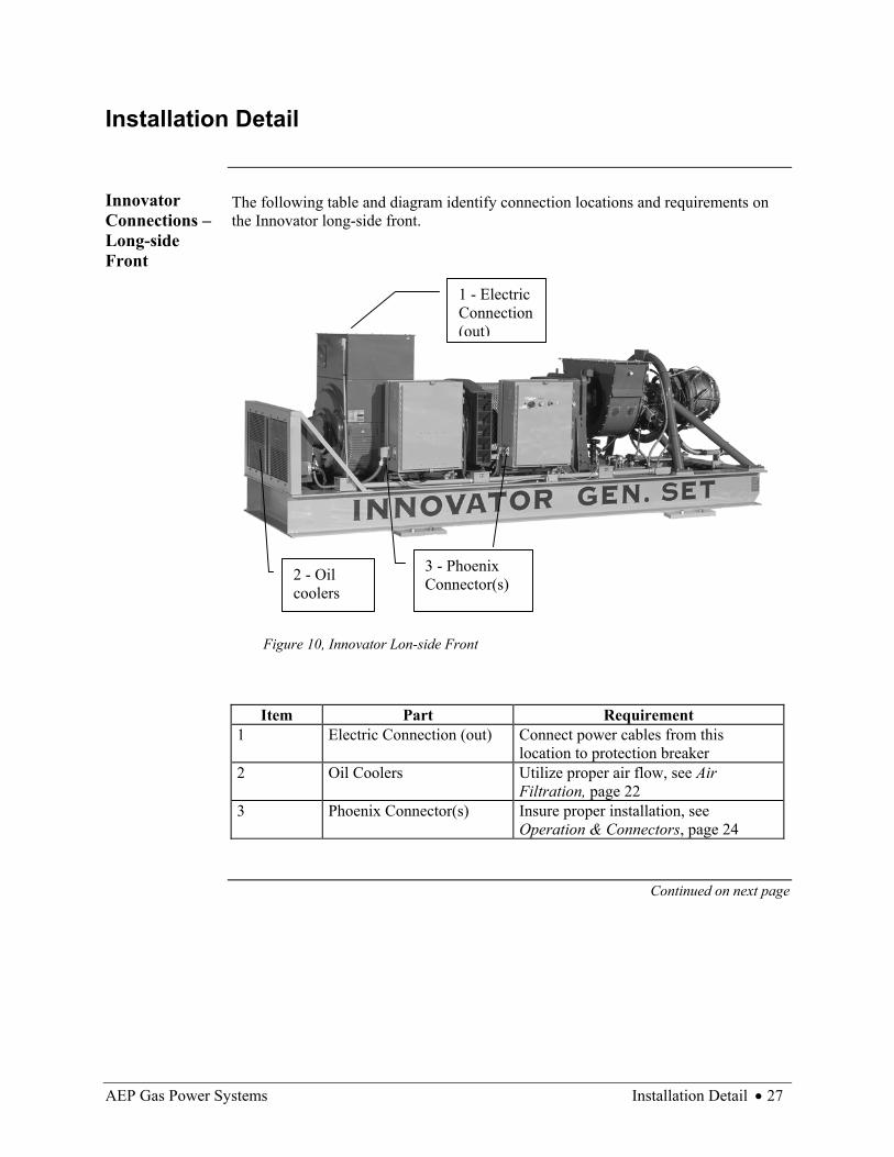
The following table and diagram identify connection locations and requirements on the Innovator long-side front.
Figure 10, Innovator Lon-side Front
Item Part Requirement 1 Electric Connection (out) Connect power cables from this
location to protection breaker 2 Oil Coolers Utilize proper air flow, see Air
Filtration, page 22 3 Phoenix Connector(s) Insure proper installation, see
Operation & Connectors, page 24
Continued on next page
3 - Phoenix Connector(s) 2 - Oil
coolers
1 - Electric Connection (out)
28 • Installation Detail AEP Gas Power Systems
Installation Detail, Continued
Innovator Connections – Long-side Back
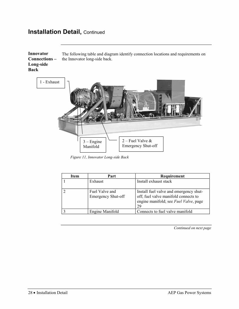
The following table and diagram identify connection locations and requirements on the Innovator long-side back.
Figure 11, Innovator Long-side Back
Item Part Requirement 1 Exhaust Install exhaust stack
2 Fuel Valve and
Emergency Shut-off Install fuel valve and emergency shut-off; fuel valve manifold connects to engine manifold; see Fuel Valve, page 29
3 Engine Manifold Connects to fuel valve manifold
Continued on next page
2 – Fuel Valve & Emergency Shut-off
1 - Exhaust
3 – Engine Manifold

AEP Gas Power Systems Generator Storage and Preservation • 29
Installation Detail, Continued
Fuel Valve Below is a close-up view of the fuel valve components.
Figure 12, Fuel Valve
Phoenix Connector
Several Phoenix Connectors require installation on the Innovator. Below is a close-up view of one.
Figure 13, Phoenix Connector
Emergency Shut-off
Fuel Valve Hose connections

30 • Generator Storage and Preservation AEP Gas Power Systems
Generator Storage and Preservation
Overview If the generator is inactive or disconnected for a month or longer, the machine needs
to be inspected. Take the following steps to maintain the equipment’s condition.
Scenario Actions Disconnected and Stored • Rotate the turbine shaft at least monthly to
reduce bearing wear.
Do not store the machine where there is a high degree of vibration that will wear the bearings at rest.
• Observe finished surfaces of the machine. If
corrosion is forming, remove rust and coat with a rust preventative such as a light oil or silicone-based product such as WD40.
• Check oil tanks for water condensation and drain if water is found.
• Keep under cover to minimize damage from weather conditions.
Unit is Connected but Inactive
• Rotate the turbine shaft. • Check oil tanks for water condensation and
drain if water is found. • Inspect piping for damage that may result in
leaks and repair if found. • Inspect for unsafe conditions.
AEP Gas Power Systems Computer System • 31
Computer System
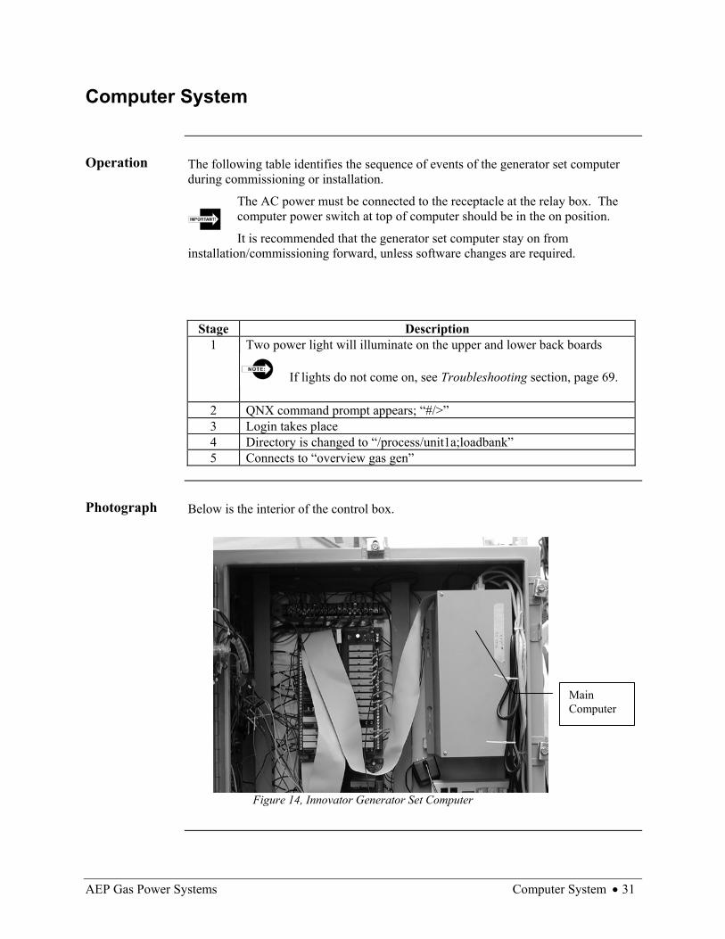
Operation The following table identifies the sequence of events of the generator set computer
during commissioning or installation.
The AC power must be connected to the receptacle at the relay box. The computer power switch at top of computer should be in the on position.
It is recommended that the generator set computer stay on from installation/commissioning forward, unless software changes are required.
Stage Description 1 Two power light will illuminate on the upper and lower back boards
If lights do not come on, see Troubleshooting section, page 69.
2 QNX command prompt appears; “#/>” 3 Login takes place 4 Directory is changed to “/process/unit1a;loadbank” 5 Connects to “overview gas gen”
Photograph Below is the interior of the control box.
Figure 14, Innovator Generator Set Computer
Main Computer

AEP Gas Power Systems Overview • 33
Operation and Daily Maintenance Overview
Introduction
This chapter provides instruction on generator set operation, daily maintenance and emergency shutdown features.
Follow all safety requirements provided by plant safety manual and local, state and federal codes.
In This Chapter
This chapter contains the following topics:
Topic See Page Initial Start Check List 35 Daily Running Check List 38 Weekly Running Check List 41 30-Day Restart and Monthly Running Check List 42 How to Start Generator 43 Post-Run Check (Shut Down) 44 Emergency Shut Down 45 Computer Operation 46
Continued on next page

34 • Overview AEP Gas Power Systems
Overview, Continued
Utility Interconnection Mode
Below is a flowchart of the operation of the generator set with a transfer switch between customer load and utility interconnection.
The transformer may also be located between transfer switch and utility rather than protection breaker and transfer switch shown here.
SynchronizingSwitchgear
Innovatorgenerator set
Transformer(See note above)
Load
ProtectionBreaker Transfer Switch
Utility
Figure 15, Flowchart of Operation of Generator Set with Utility
Island Mode Below is a flowchart of the operation of the generator set with customer load.
InnovatorGenerator set TransformerProtection
Breaker Load
Figure 16, Flowchart of Operation of Generator Set with Customer Load
AEP Gas Power Systems Initial Start Check List • 35
Initial Start Check List
About This Check List
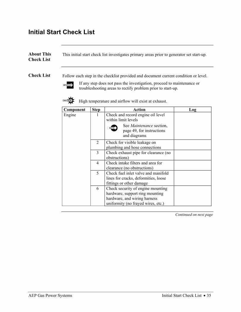
This initial start check list investigates primary areas prior to generator set start-up.
Check List
Follow each step in the checklist provided and document current condition or level.
If any step does not pass the investigation, proceed to maintenance or troubleshooting areas to rectify problem prior to start-up.
High temperature and airflow will exist at exhaust.
Component Step Action Log Engine 1 Check and record engine oil level
within limit levels See Maintenance section, page 49, for instructions and diagrams
2 Check for visible leakage on plumbing and hose connections
3 Check exhaust pipe for clearance (no obstructions)
4 Check intake filters and area for clearance (no obstructions)
5 Check fuel inlet valve and manifold lines for cracks, deformities, loose fittings or other damage
6 Check security of engine mounting hardware, support ring mounting hardware, and wiring harness uniformity (no frayed wires, etc.)
Continued on next page
36 • Initial Start Check List AEP Gas Power Systems
Initial Start Check List, Continued
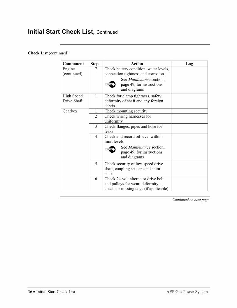
Check List (continued)
Component Step Action Log Engine (continued)
7 Check battery condition, water levels, connection tightness and corrosion
See Maintenance section, page 49, for instructions and diagrams
High Speed Drive Shaft
1 Check for clamp tightness, safety, deformity of shaft and any foreign debris
Gearbox 1 Check mounting security 2 Check wiring harnesses for
uniformity
3 Check flanges, pipes and hose for leaks
4 Check and record oil level within limit levels
See Maintenance section, page 49, for instructions and diagrams
5 Check security of low-speed drive shaft, coupling spacers and shim packs
6 Check 24-volt alternator drive belt and pulleys for wear, deformity, cracks or missing cogs (if applicable)
Continued on next page

AEP Gas Power Systems Initial Start Check List • 37
Initial Start Check List, Continued
Check List (continued)
Component Step Action Log Low-Speed Drive Shaft
1 Check to insure the guard is installed and secure
2 Check security of coupling spacers and shim packs on both ends
3 Check for applicable warning signs of shim pack breaking; rust streaks for example
Generator 1 Check mounting hardware to insure tightness
2 Check for visible grease leakage from bearings
3 Check security of high-voltage connections
4 Check grounding grid connection 5 Check to be sure inlet and exhaust air
passages are clear
Oil Cooling System
1 Check plumbing hoses and flanges for leakage
2 Check oil filters to insure tight fit, no damage or leakage (engine and gearbox)
See Maintenance section, page 50, for instructions and diagrams
3 Check oil cooling fans for obstructions
4 Check oil cooler exit for obstructions Control System
1 Check relay box and control box for mounting security; check for foreign objects and to be sure inlet and exhaust air passages are clear
2 Check security of Phoenix connectors to insure no damage, still in sockets and locks down
3 Check for standing alarms Skid 1 Check skid isolation-vibration pads
for condition (cracks, bends)
2 Check skid general condition (welds, level)
38 • Daily Running Check List AEP Gas Power Systems
Daily Running Check List
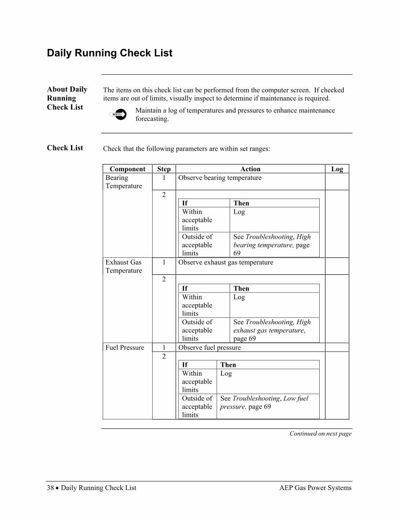
About Daily Running Check List
The items on this check list can be performed from the computer screen. If checked items are out of limits, visually inspect to determine if maintenance is required.
Maintain a log of temperatures and pressures to enhance maintenance forecasting.
Check List Check that the following parameters are within set ranges:
Component Step Action Log Bearing Temperature
1 Observe bearing temperature
2 If Then Within acceptable limits
Log
Outside of acceptable limits
See Troubleshooting, High bearing temperature, page 69
Exhaust Gas Temperature
1 Observe exhaust gas temperature
2 If Then Within acceptable limits
Log
Outside of acceptable limits
See Troubleshooting, High exhaust gas temperature, page 69
Fuel Pressure 1 Observe fuel pressure 2
If Then Within acceptable limits
Log
Outside of acceptable limits
See Troubleshooting, Low fuel pressure, page 69
Continued on next page

AEP Gas Power Systems Daily Running Check List • 39
Daily Running Check List, Continued
Check List (continued)
Component Step Action Log Generator Winding Temperatures
1 Observe winding temperatures
2 If Then Within acceptable limits
Log
Outside of acceptable limits
See Troubleshooting, High generator winding temperature, page 69
Oil Level 1 Observe oil level 2
If Then Within acceptable limits
Log
Outside of acceptable limits
See Troubleshooting, Engine oil below recommended level, page 69
Oil Pressure 1 Observer oil pressure 2
If Then Within acceptable limits
Log
Outside of acceptable limits
See Troubleshooting, High/low lube oil pressure, page 69
Oil Temperature 1 Observe oil temperature 2
If Then Within acceptable limits
Log
Outside of acceptable limits
See Troubleshooting, High/low lube oil temperature, page 69
Continued on next page
40 • Daily Running Check List AEP Gas Power Systems
Daily Running Check List, Continued
Check List (continued)
Component Step Action Log Output Voltage 1 Observe output voltage 2
If Then Within acceptable limits
Log
Outside of acceptable limits
See Troubleshooting, High/low output voltage page 69
Output kW 1 Observe output kW 2
If Then Within acceptable limits
Log
Outside of acceptable limits
See Troubleshooting, Low Output kW, page 69
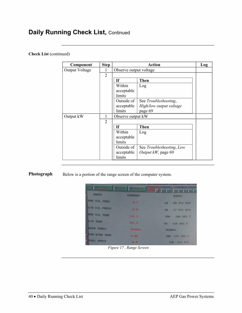
Photograph Below is a portion of the range screen of the computer system.
Figure 17 , Range Screen
AEP Gas Power Systems Weekly Running Check List • 41
Weekly Running Check List
About This Check List
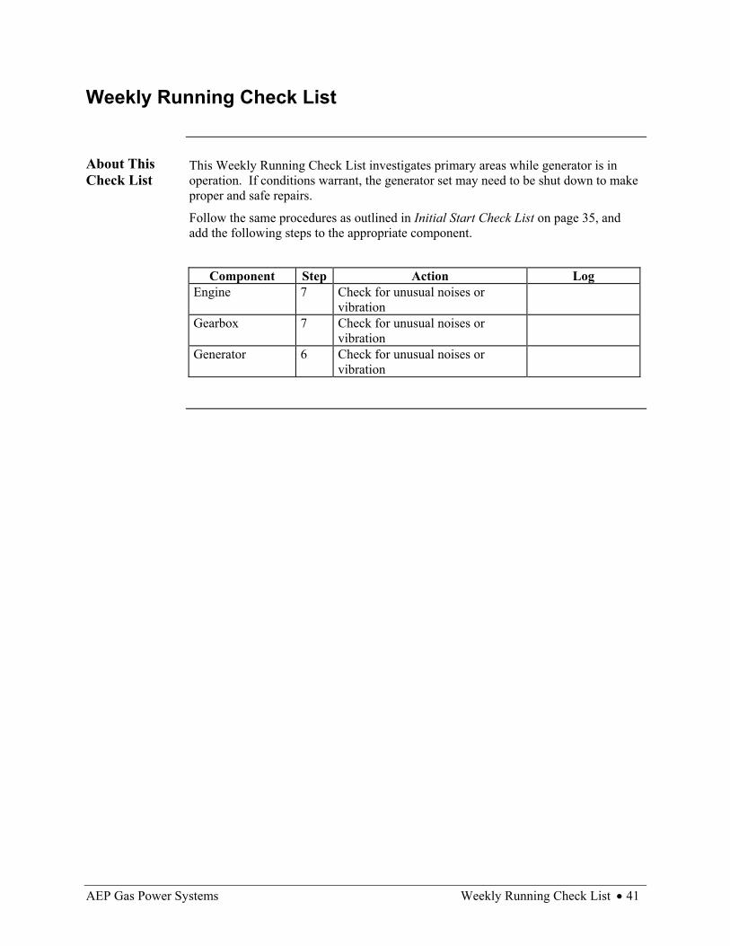
This Weekly Running Check List investigates primary areas while generator is in operation. If conditions warrant, the generator set may need to be shut down to make proper and safe repairs.
Follow the same procedures as outlined in Initial Start Check List on page 35, and add the following steps to the appropriate component.
Component Step Action Log
Engine 7 Check for unusual noises or vibration
Gearbox 7 Check for unusual noises or vibration
Generator 6 Check for unusual noises or vibration

42 • 30-Day Restart and Monthly Running Check List AEP Gas Power Systems
30-Day Restart and Monthly Running Check List
About This Check List
The 30-Day Restart and Monthly Running check list investigates primary areas prior to generator set restart and monthly running check. AEP Gas Power Systems recommends shutting down the generator set monthly and performing these checks if it is in continuous operation.
Follow the same procedures as outlined in Initial Start Check List on page 35, and add step 4 below to the Control System section.
Component Step Action Log
Control System
4 During monthly shutdown operate emergency trip to insure emergency gas shutoff valve operates properly

AEP Gas Power Systems How to Start Generator • 43
How to Start Generator
Start Sequence
Follow the steps below to start the generator set.
Step Action Result
1 Complete pre-start check form, page 35
Generator set ready for start-up
2 Push Start button (green)
Engine and gearbox pumps begin running
3 Listen for pumps Once pressure and flow are established: • Starter engages • Ignition comes on • Fuel flow initiates • Exhaust gas temperature rises • Starter disengages • Engine stabilizes at idle speed
Image Below is a picture of the Start button.
Figure 18, Start Button
Start Button

44 • Post-Run Check (Shut Down) AEP Gas Power Systems
Post-Run Check (Shut Down)
Shut-Down Sequence
Follow the steps below to shut down the generator set.
Step Action Result
1 Push Normal Stop button
The engine reduces to idle: • Customer load disconnects • Engine stabilizes for 1 to 2 minutes • Fuel flow shuts off • Engine coasts down to minimal
rotation speeds 2 Listen for pumps • Engine and gearbox pumps shut off
• Generator set is ready for pre-start sequence
Image Below is a picture of the Normal Stop button.
Figure 19, Normal Stop Button
Normal Stop Button

AEP Gas Power Systems Emergency Shut Down • 45
Emergency Shut Down
Emergency Shut-Down Sequence
Follow the steps below to shut down the generator set in an emergency situation.
Step Action Result 1 Push Emergency Shut-Down button (red)
• Emergency fuel valve
closes • Fuel control closes • Engine goes to
immediate shut down 2 Wait for generator set to shut down • Coast-down time is 3 to 5
minutes
Image Below is a picture of the Emergency Stop button.
Figure 20, Emergency Stop Button
Emergency Stop Button
46 • Computer Operation AEP Gas Power Systems
Computer Operation
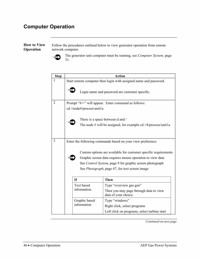
How to View Operation
Follow the procedures outlined below to view generator operation from remote network computer.
The generator unit computer must be running, see Computer System, page 31.
Step Action 1 Start remote computer then login with assigned name and password.
Login name and password are customer specific.
2 Prompt “#/>” will appear. Enter command as follows:
cd //node#/process/unit1a
There is a space between d and / The node # will be assigned, for example cd //4/process/unit1a
3 Enter the following commands based on your view preference:
Custom options are available for customer specific requirements Graphic screen data requires mouse operation to view data See Control System, page 9 for graphic screen photograph
See Photograph, page 47, for text screen image
If Then Text based information
Type “overview gas gen” Then you may page through data to view data of your choice.
Graphic based information
Type “windows” Right click, select programs Left click on programs, select turbine start
Continued on next page

AEP Gas Power Systems Computer Operation • 47
Computer Operation, Continued
Shutdown Follow the instructions below to shut down viewing capability.
If Then Text based information Type “vx” Graphics based information
• Close window as normal by clicking on “x” in upper right corner
• Prompt “#/>” will appear, type “cd /” then hit enter
• Shut down remote computer by power in off position
There is a space between d and /
Photograph See image below for text based information screen.
Figure 21, Text information screen


AEP Gas Power Systems Overview • 49
Maintenance Overview
Introduction This chapter leads you step-by-step through the general maintenance of the generator
set including the oil, fuel, air, and battery systems.
Daily Maintenance Reminder
Periodically look for peeling paint, cracked hoses, corrosion, etc. This should be an ongoing daily practice. If you encounter any of these, refer to the Troubleshooting section, page 69, for guidance.
In This Chapter
This chapter contains the following topics:
Topic See Page Oil System 50 Fuel System 57 Air System 59 Battery Maintenance 60 Engine Compressor Section 63 Major Maintenance Schedule 64 Heavy Maintenance 65

50 • Oil System AEP Gas Power Systems
Oil System
About Oil System
Recommended oil changes are every 2,500 operating hours for the gear box oil system or as needed based on operating conditions and 10,000 operating hours for the engine oil system or every 18 months which ever comes first. Oil filter changes are recommended every 1000 hours or as needed based on operating conditions. More frequent changes may be required in severe operating conditions.
Dispose of oil using current approved local, state and federal procedures.
Following the initial 350 operating hours, change the gearbox oil as part of the initial break-in.
Material List (Customer - Supplied Parts)
Keep the following items on hand when conducting maintenance on the oil system:
• Oil filter • Approved oil, (MIL-L-23699 Aeroshell 500 Turbine Oil) 42 gallons total
(28 gallons for engine, 14 gallons for gearbox) • Approved 30-gallon container (engine) or 15-gallon container (gearbox) • Type-compatible suction pump (Suction method only)
Predictive Maintenance
The following predictive maintenance is recommended. They may give indications of the overall condition of the lubricated components and be indicative of any future maintenance needs.
• Take oil samples every 6 months and send for laboratory analysis to check for oil condition, contaminants, or foreign materials
• Cut used oil filters open and visually inspect for metal filings or other foreign materials. Flakes of metal appearing in the filter, is a sign to perform maintenance. Determine source of metal.
Continued on next page

AEP Gas Power Systems Oil System • 51
Oil System, Continued
Methods to Change Oil
There are two methods that can be used to change the oil.
• Suction method • Drain plug method Use suction method of oil changing if the drain plug is not accessible on the bottom of oil tank.
Images Below is a picture of one view of the oil filters.
Figure 22, Oil Filters
Continued on next page
Oil Filters
52 • Oil System AEP Gas Power Systems
Oil System, Continued
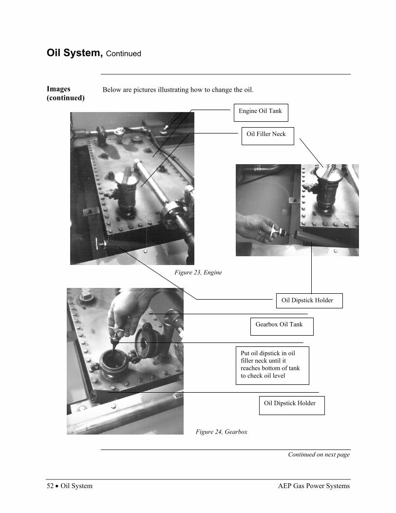
Images (continued)
Below are pictures illustrating how to change the oil.
Figure 23, Engine
Figure 24, Gearbox
Continued on next page
Engine Oil Tank
Oil Filler Neck
Oil Dipstick Holder
Put oil dipstick in oil filler neck until it reaches bottom of tank to check oil level
Oil Dipstick Holder
Gearbox Oil Tank
AEP Gas Power Systems Oil System • 53
Oil System, Continued
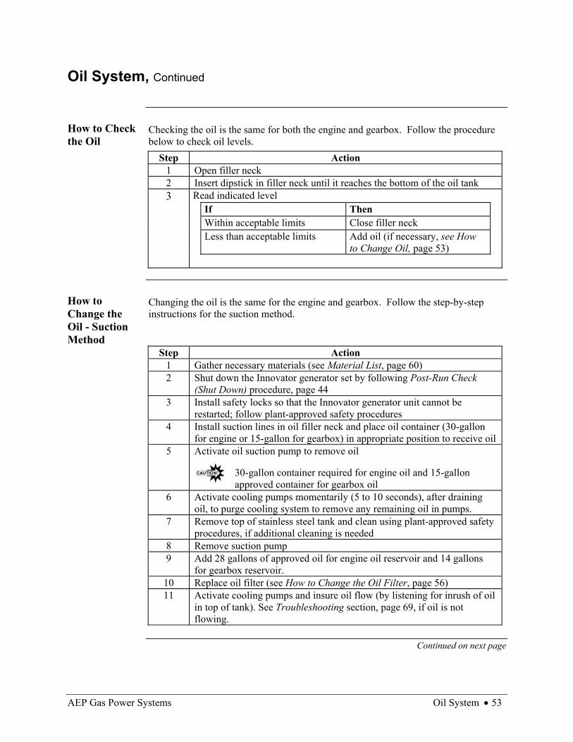
How to Check the Oil
Checking the oil is the same for both the engine and gearbox. Follow the procedure below to check oil levels.
Step Action 1 Open filler neck 2 Insert dipstick in filler neck until it reaches the bottom of the oil tank 3 Read indicated level If Then Within acceptable limits Close filler neck Less than acceptable limits Add oil (if necessary, see How
to Change Oil, page 53)
How to Change the Oil - Suction Method
Changing the oil is the same for the engine and gearbox. Follow the step-by-step instructions for the suction method.
Step Action 1 Gather necessary materials (see Material List, page 60) 2 Shut down the Innovator generator set by following Post-Run Check
(Shut Down) procedure, page 44 3 Install safety locks so that the Innovator generator unit cannot be
restarted; follow plant-approved safety procedures 4 Install suction lines in oil filler neck and place oil container (30-gallon
for engine or 15-gallon for gearbox) in appropriate position to receive oil 5 Activate oil suction pump to remove oil
30-gallon container required for engine oil and 15-gallon approved container for gearbox oil
6 Activate cooling pumps momentarily (5 to 10 seconds), after draining oil, to purge cooling system to remove any remaining oil in pumps.
7 Remove top of stainless steel tank and clean using plant-approved safety procedures, if additional cleaning is needed
8 Remove suction pump 9 Add 28 gallons of approved oil for engine oil reservoir and 14 gallons
for gearbox reservoir. 10 Replace oil filter (see How to Change the Oil Filter, page 56) 11 Activate cooling pumps and insure oil flow (by listening for inrush of oil
in top of tank). See Troubleshooting section, page 69, if oil is not flowing.
Continued on next page

54 • Oil System AEP Gas Power Systems
Oil System, Continued
Images Below are pictures illustrating oil change by suction method.
Figure 25, Changing Oil by Suction Method
Continued on next page
Suction Line in Oil Filler Neck
Suction Pump and Container
Oil Filler Neck
Add Approved Oil

AEP Gas Power Systems Oil System • 55
Oil System, Continued
How to Change the Oil – Drain- Plug Method
Changing the oil is the same for the engine and gearbox. Follow the procedures below if the drain-plug method is utilized.
Step Action 1 Gather necessary materials (see Material List, page 60) 2 Shut down the Innovator generator unit by following Normal shut-off
procedure, page 44 3 Install safety locks so that the Innovator generator unit cannot be
restarted. Follow plant-approved safety procedures. 4 Put 30-gallon (engine) or 15-gallon (gearbox) minimum container under
drain plug located at bottom of stainless steel tank 5 Remove drain plug 6 Activate cooling pumps momentarily (5 to 10 seconds), after draining
oil, to purge cooling system to remove any remaining oil in pumps 7 Remove top of stainless steel tank and clean using plant approved safety
procedures, if additional cleaning is needed 8 Replace plug on bottom of tank 9 Add 28 gallons of approved oil for engine oil reservoir and 14 gallons
for gear box reservoir 10 Replace oil filter (see How to Change the Oil Filter, page 56) 11 Activate cooling pumps and insure oil flow (by listening for inrush of oil
in top of tank). See Troubleshooting section, page 69, if oil is not flowing.
Continued on next page

56 • Oil System AEP Gas Power Systems
Oil System, Continued
How to Change the Oil Filter
Follow the steps below to change the oil filter.
Step Action 1 Gather necessary materials (see Material List, page 60) 2 Shut cooling pumps down (engine and transmission) 3 Remove filter by spinning off (use appropriate tools) 4 Fill new filter with two quarts of approved oil 5 Install new filter by spinning on, as stated by manufacturer
recommendations 6 Reenergize cooling pumps 7 Check for leaks
Image Below is a picture illustrating how to change the filter.
Figure 26, How to Change the Filter
Remove Filter by Spinning Off
AEP Gas Power Systems Fuel System • 57
Fuel System
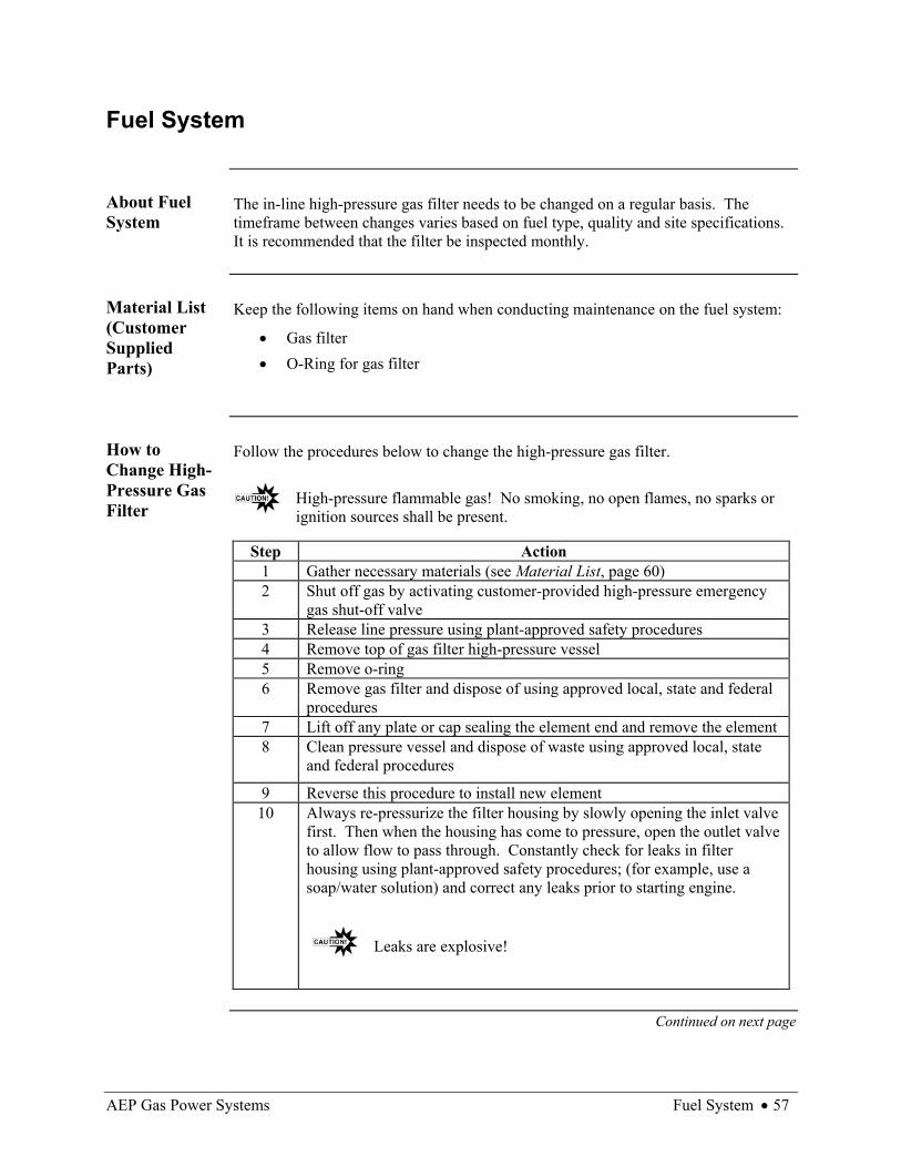
About Fuel System
The in-line high-pressure gas filter needs to be changed on a regular basis. The timeframe between changes varies based on fuel type, quality and site specifications. It is recommended that the filter be inspected monthly.
Material List (Customer Supplied Parts)
Keep the following items on hand when conducting maintenance on the fuel system:
• Gas filter • O-Ring for gas filter
How to Change High-Pressure Gas Filter
Follow the procedures below to change the high-pressure gas filter.
High-pressure flammable gas! No smoking, no open flames, no sparks or ignition sources shall be present.
Step Action 1 Gather necessary materials (see Material List, page 60) 2 Shut off gas by activating customer-provided high-pressure emergency
gas shut-off valve 3 Release line pressure using plant-approved safety procedures 4 Remove top of gas filter high-pressure vessel 5 Remove o-ring 6 Remove gas filter and dispose of using approved local, state and federal
procedures 7 Lift off any plate or cap sealing the element end and remove the element 8 Clean pressure vessel and dispose of waste using approved local, state
and federal procedures
9 Reverse this procedure to install new element 10
Always re-pressurize the filter housing by slowly opening the inlet valve first. Then when the housing has come to pressure, open the outlet valve to allow flow to pass through. Constantly check for leaks in filter housing using plant-approved safety procedures; (for example, use a soap/water solution) and correct any leaks prior to starting engine.
Leaks are explosive!
Continued on next page

58 • Fuel System AEP Gas Power Systems
Fuel System, Continued
Images Below are pictures of the fuel filter.
Figure 27, Fuel Filter
Fuel Filter

AEP Gas Power Systems Air System • 59
Air System
Overview Customer may supply the air filter based on site-specific installation. See specific air
filter manufacturer instructions/recommendations for maintenance. Air filters are site-specific and supplied through various manufacturers and contractors. See specifications for each.
60 • Battery Maintenance AEP Gas Power Systems
Battery Maintenance
About Battery Maintenance
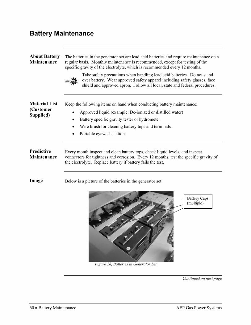
The batteries in the generator set are lead acid batteries and require maintenance on a regular basis. Monthly maintenance is recommended, except for testing of the specific gravity of the electrolyte, which is recommended every 12 months.
Take safety precautions when handling lead acid batteries. Do not stand over battery. Wear approved safety apparel including safety glasses, face shield and approved apron. Follow all local, state and federal procedures.
Material List (Customer Supplied)
Keep the following items on hand when conducting battery maintenance:
• Approved liquid (example: De-ionized or distilled water) • Battery specific gravity tester or hydrometer • Wire brush for cleaning battery tops and terminals • Portable eyewash station
Predictive Maintenance
Every month inspect and clean battery tops, check liquid levels, and inspect connectors for tightness and corrosion. Every 12 months, test the specific gravity of the electrolyte. Replace battery if battery fails the test.
Image Below is a picture of the batteries in the generator set.
Figure 28, Batteries in Generator Set
Continued on next page
Battery Caps (multiple)
AEP Gas Power Systems Battery Maintenance • 61
Battery Maintenance, Continued
How to Check Battery Levels
Follow the procedures below and manufacturer’s recommendations to check battery levels.
Step Action
1 Remove battery caps 2 Check if liquid is at acceptable indicated levels (bottom of filler neck)
If Then Yes Replace caps No Go to How to Refill Batteries; page 61
3 Repeat for each battery
How to Refill Batteries
Follow the step-by-step procedures below and manufacturer’s recommendations to refill batteries.
Step Action
1 Gather necessary materials (see Material List, page 60) 2 Remove battery caps 3 Fill battery with approved liquid to indicated levels (bottom of filler
neck) 4 Replace battery caps 5 Repeat for each battery
How to Clean Batteries
Follow the step-by-step procedures below and manufacturer’s recommendations to clean batteries.
Step Action 1 Gather necessary materials (see Material List, page 60) 2 Check battery tops and caps for corrosion If Then Corroded Use wire brush to remove corrosion Not Corroded Go to step 3
3 Repeat for each battery
Continued on next page

62 • Battery Maintenance AEP Gas Power Systems
Battery Maintenance, Continued
How to Test Specific Gravity of Battery
Follow the procedures on battery tester or hydrometer and below.
Battery tester or hydrometer may be available from an auto parts supplier.
Step Action
1 Gather necessary materials (see Material List, page 60) 2 Follow instruction on tester to draw battery fluid into tester 3 Read instructions on tester to observe cell condition. Read indicated
level If Then Within acceptable
limits Completed, go to step 5
Outside of acceptable limits
Recharge battery, go to step 4
4 Follow instructions below for recharged battery. If recharged battery is Then Within acceptable limits Completed, go to step 5 Outside of acceptable limits Replace battery, go to step 5
5 Repeat process for each battery starting at step 2
AEP Gas Power Systems Engine Compressor Section • 63
Engine Compressor Section
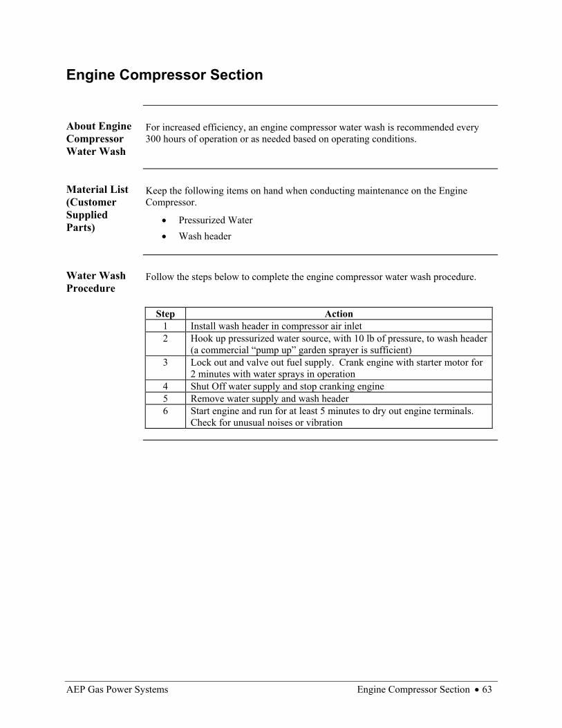
About Engine Compressor Water Wash
For increased efficiency, an engine compressor water wash is recommended every 300 hours of operation or as needed based on operating conditions.
Material List (Customer Supplied Parts)
Keep the following items on hand when conducting maintenance on the Engine Compressor.
• Pressurized Water • Wash header
Water Wash Procedure
Follow the steps below to complete the engine compressor water wash procedure.
Step Action
1 Install wash header in compressor air inlet 2 Hook up pressurized water source, with 10 lb of pressure, to wash header
(a commercial “pump up” garden sprayer is sufficient) 3 Lock out and valve out fuel supply. Crank engine with starter motor for
2 minutes with water sprays in operation 4 Shut Off water supply and stop cranking engine 5 Remove water supply and wash header 6 Start engine and run for at least 5 minutes to dry out engine terminals.
Check for unusual noises or vibration
64 • Major Maintenance Schedule AEP Gas Power Systems
Major Maintenance Schedule
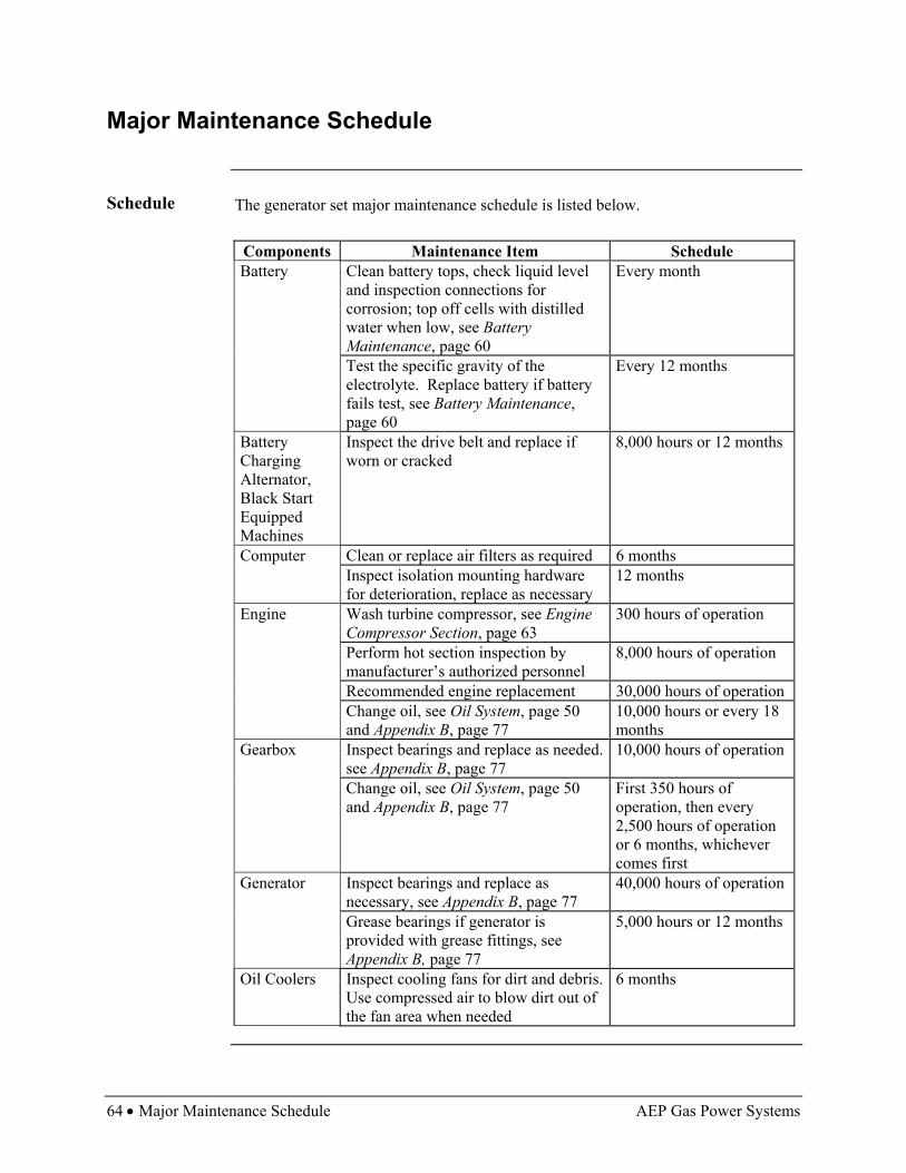
Schedule The generator set major maintenance schedule is listed below.
Components Maintenance Item Schedule Battery Clean battery tops, check liquid level
and inspection connections for corrosion; top off cells with distilled water when low, see Battery Maintenance, page 60
Every month
Test the specific gravity of the electrolyte. Replace battery if battery fails test, see Battery Maintenance, page 60
Every 12 months
Battery Charging Alternator, Black Start Equipped Machines
Inspect the drive belt and replace if worn or cracked
8,000 hours or 12 months
Computer Clean or replace air filters as required 6 months Inspect isolation mounting hardware
for deterioration, replace as necessary 12 months
Engine Wash turbine compressor, see Engine Compressor Section, page 63
300 hours of operation
Perform hot section inspection by manufacturer’s authorized personnel
8,000 hours of operation
Recommended engine replacement 30,000 hours of operation Change oil, see Oil System, page 50
and Appendix B, page 77 10,000 hours or every 18 months
Gearbox Inspect bearings and replace as needed. see Appendix B, page 77
10,000 hours of operation
Change oil, see Oil System, page 50 and Appendix B, page 77
First 350 hours of operation, then every 2,500 hours of operation or 6 months, whichever comes first
Generator Inspect bearings and replace as necessary, see Appendix B, page 77
40,000 hours of operation
Grease bearings if generator is provided with grease fittings, see Appendix B, page 77
5,000 hours or 12 months
Oil Coolers Inspect cooling fans for dirt and debris. Use compressed air to blow dirt out of the fan area when needed
6 months

AEP Gas Power Systems Heavy Maintenance • 65
Heavy Maintenance
Heavy Maintenance
It is recommended that only qualified personnel perform heavy maintenance.
• Provided by assembler – AEP Gas Power Systems authorized service shops and/or personnel
• Qualifying training available on request


AEP Gas Power Systems Recommended Parts List • 67
Maintenance Parts Recommended Parts List
Introduction The following is a list of recommended maintenance parts.
Parts List The recommended parts list is included below for your convenience. Also see
Appendix A, page 75.
Not all brands of oil are compatible with each other.
Name Part Number Recommended
Manufacturer Oil (Engine and Gearbox)
MIL-L-23699
Shell Oil Company AeroShell 500 Turbine Oil
Oil Filter (includes one part #603M 3 micron microglass filter cartridge with a viton seal
520P-15-0-0-603M-N Norman Filter Company
Fuel Filter Housing F2-275F Element 2015K5
FilterFab Manufacturing
O-Ring for Fuel (Gas) Filter
52939P001 FilterFab Manufacturing
Grease for Generator Bearings
Asonic GHY72 #611235 Art. # 094049
Kluber Lubrication
Modules (1) Digital Input # 70G-IDC5 (2) Digital Outputs # 70G-0DC5MA (2) Analog Inputs # 73G-11420 (1) Analog Output # 73G-0V10B (1) RTD # 73G-ITR100
Garyhill Corporation
Pump Motors Cat.# 108051.00 Model # C4D17NK10C
Leeson Electric Corporation
Pumps Haight 1-8 D/DR Haight 10-40 D/DR
Baker Manufacturing Company
Fan Motors 199901G0CF SPAL of Italy

AEP Gas Power Systems General Topics • 69
Troubleshooting General Topics
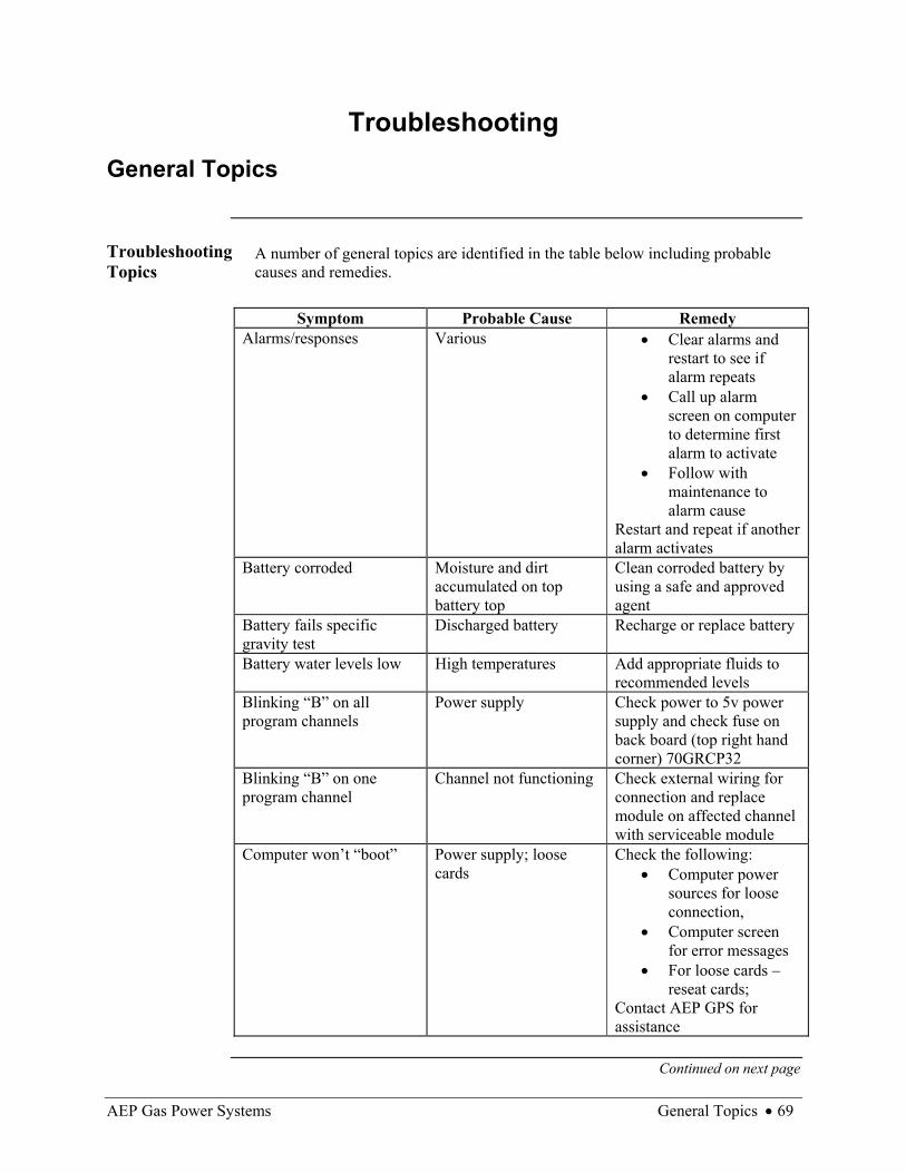
Troubleshooting Topics
A number of general topics are identified in the table below including probable causes and remedies.
Symptom Probable Cause Remedy
Alarms/responses Various • Clear alarms and restart to see if alarm repeats
• Call up alarm screen on computer to determine first alarm to activate
• Follow with maintenance to alarm cause
Restart and repeat if another alarm activates
Battery corroded Moisture and dirt accumulated on top battery top
Clean corroded battery by using a safe and approved agent
Battery fails specific gravity test
Discharged battery Recharge or replace battery
Battery water levels low High temperatures Add appropriate fluids to recommended levels
Blinking “B” on all program channels
Power supply Check power to 5v power supply and check fuse on back board (top right hand corner) 70GRCP32
Blinking “B” on one program channel
Channel not functioning Check external wiring for connection and replace module on affected channel with serviceable module
Computer won’t “boot” Power supply; loose cards
Check the following: • Computer power
sources for loose connection,
• Computer screen for error messages
• For loose cards – reseat cards;
Contact AEP GPS for assistance
Continued on next page

70 • General Topics AEP Gas Power Systems
General Topics, Continued
Troubleshooting Topics (continued)
Symptom Probable Cause Remedy Control malfunctions Failed sending unit Check hardware inputs for
proper signals; if signals are okay, call AEP GPS for assistance
Cracks/rust/peeling paint/corrosion
Paint chipped or worn Contact AEP Gas Power System or authorized agent for paint type
Engine oil below recommended level
Possible oil leak Add oil to recommended level, check for leaking and repair
Engine stops No fuel, no electric Check fuel system for correct pressure and unobstructed flow, check electrical system
Engine won’t start No electric or no fuel Check the following: • Starter battery
voltage • For N1 indication
upon starter engagement (N1 speed should increase when starter engages)
• Fuel pressure • Cycle fuel valve
(by pulling cannon plug off valve and replacing)
If maximum N1 obtained maximum EGT, maximum fuel valve opening then call AEP GPS for assistance
Frayed wires Animals chewing wires Repair insulation
Continued on next page

AEP Gas Power Systems General Topics • 71
General Topics, Continued
Troubleshooting Topics (continued)
Symptom Probable Cause Remedy High/low lube oil pressure Failed pressure sensor,
low oil level Low Check oil levels and add if necessary, installed gauge on inlet oil pressure line to verify pressure High Install gauge to verify pressure, check pump pressure relief valve for proper operation, check engine inlet oil screen and clean
High/low lube oil temperature
Low oil, oil cooling system
High Check for proper level in oil tank, check for cooling pump operation, check radiator fans and air flow to radiators for restrictions Low Allow engine to warm up
High/low output voltage Utility interconnection mode – Gird voltage most likely high/low Isolated mode – Difficulty with automatic voltage control (AVR)
Utility interconnection mode – Check grid voltages Isolated mode – Check AVR for proper setting; can adjust voltage by AVR or replace AVR if necessary
High vibration MIS alignment Determine frequency of vibration to determine if cause is on generator end or the engine end of the unit; Call AEP GPS for assistance
High bearing temperature Temperature pickup failure
Check bearing temperature with another sources to verify sending unit is working properly; rotate shaft and listen for excessive noise, check oil temperature and pressure
Continued on next page

72 • General Topics AEP Gas Power Systems
General Topics, Continued
Troubleshooting Topics (continued)
Symptom Probable Cause Remedy High exhaust gas temperature
Inlet air blockage • Check inlet air filters for blockage or dirt, replace or clean;
• Check for restriction in inlet air duct;
• Check to see if exhaust is entrained in inlet air, heat rejected from another source is taken into inlet of engine
High generator winding temperature
Generator cooling air blockage
Inspect inlets to generator cooling air and remove blockage
Leak in plumbing/hoses Wear, loose joints Replace hoses, tighten plumbing joints
Low fuel pressure Blockage in fuel system; improper supply
Check fuel filter for dirt and blockage, replace or clean;
• if using gas compressor - check for proper fuel outlet pressures;
• if pipeline supply check for proper delivery pressure and call supplier;
• if liquid system check for blockage in fuel line
Low kW output Breaker Check electric output breaker to verify it is closed, verify load.
Continued on next page

AEP Gas Power Systems General Topics • 73
General Topics, Continued
Troubleshooting Topics (continued)
Symptom Probable Cause Remedy No A/C power Power cables Check power supply cord
and check GFI trip-reset Oil cooling system fails (oil not flowing)
Pump motor, fan motor failed
Contact AEP Gas Power System or authorized agent
Oil filter leaking Gasket failure, defective or loose filter, possible puncture
Tighten or install new oil filter
Two power lights are not illuminated on the upper and lower back boards
Power supply; computer card
Check 5 volt logic power; If red lights aren’t on call AEP GPS for assistance


AEP Gas Power Systems Manufacturer Information List • 75
Appendix A Manufacturer Information List
Introduction The manufacturer contact information list below is provided for your convenience.
FilterFab Manufacturing 3709 Greengarden Road Aliquippa, PA 15001
Phone: (724) 375-6927 (800) 899-6927 Kluber Lubrication See website, www.kluberna.com for local distributor Norman Filter Company 9850 South Industrial Drive Bridgeview, IL 60455 Phone: (708) 430-4000 (800) 207-6045 Shell Oil Company (local distributor)

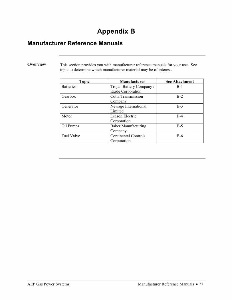
AEP Gas Power Systems Manufacturer Reference Manuals • 77
Appendix B Manufacturer Reference Manuals
Overview This section provides you with manufacturer reference manuals for your use. See
topic to determine which manufacturer material may be of interest.
Topic Manufacturer See Attachment Batteries Trojan Battery Company /
Exide Corporation B-1
Gearbox Cotta Transmission Company
B-2
Generator Newage International Limited
B-3
Motor Leeson Electric Corporation
B-4
Oil Pumps Baker Manufacturing Company
B-5
Fuel Valve Continental Controls Corporation
B-6


AEP Gas Power Systems Material Safety Data Sheets • 79
Appendix C Material Safety Data Sheets
MSDS This Appendix contains Material Safety Data Sheets. Reference the table below for
the MSDS of interest.
MSDS # Description See Attachment 857490E-01 Aeroshell Turbine Oil 500 C-1 9140002474363 Fuel Oil #2 (Diesel fuel) C-2 614000F036165 Lead-Acid Battery C-3 CSW7000101 Natural Gas C-4


AEP Gas Power Systems Drawings • 81
Appendix D Drawings
Innovator Drawings
This Appendix includes drawings for the Innovator generator set. Reference the table below for the drawing of interest.
Description Drawing Number
Genset Steel Outline S-1001
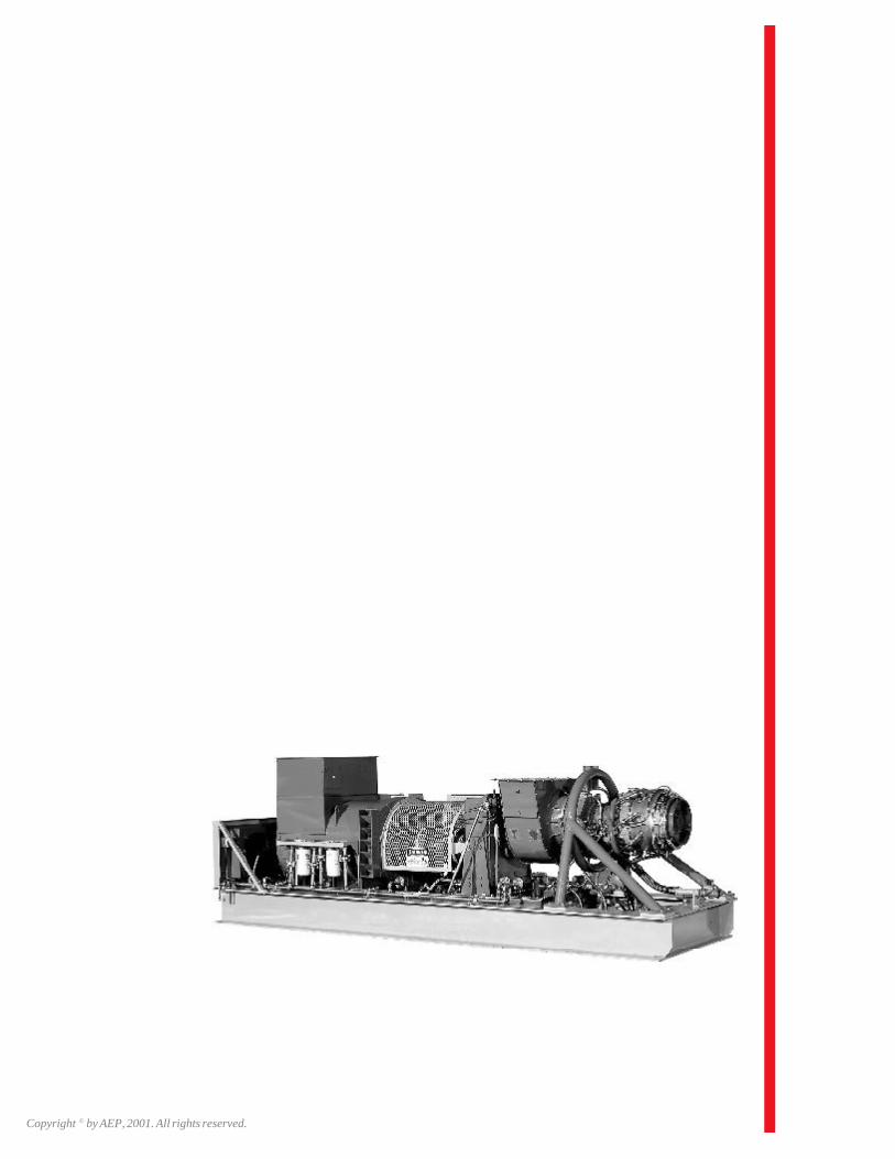
Copyright © by AEP, 2001. All rights reserved.