generative shape design - detailed steps
TRANSCRIPT

� &$7,$�7UDLQLQJ�� 'HWDLOHG�6WHSV�
&23<5,*+7�'$66$8/7�6<67(0(6����� Version 5 Release 7 June 2001 FOR-CAT-E-GSD-FD-V5R7
���������������������������� ����������DDeettaaiilleedd SStteeppss

&$7,$�*HQHUDWLYH�6KDSH�'HVLJQ� � ([HUFLVHV��
&23<5,*+7�'$66$8/7�6<67(0(6������ � ��� �
���������������Knob..................................................................................................................................................................3
Step 1: Creating the Wireframe Geometry ..................................................................................................3
Step 2: Creating the Basic Surfaces............................................................................................................6
Step 3: Performing Operations the Basic Surfaces.....................................................................................7
Step 4: Analyzing and Modifying the draft angle.......................................................................................14
Step 5: Offsetting a solid ............................................................................................................................16
Wireframe Recapitulation Exercise ...............................................................................................................21
Surface Recapitulation Exercise....................................................................................................................25
Operation Recapitulation Exercise ................................................................................................................34
Advanced Tasks Recapitulation Exercise .....................................................................................................47
Plastic Bottle...................................................................................................................................................58
Step 1: Bottle Bottom Creation ..................................................................................................................58
Step 2: Bottle Body Creation......................................................................................................................82
Step 3: Bottleneck ....................................................................................................................................102
Step 4: Assemble the three bodies..........................................................................................................132
Step 5 : Create the Bottleneck Screw......................................................................................................148
Space Mouse Base Solution........................................................................................................................161
Step 1: Create the Filleted pad. ...............................................................................................................161
Step 2: Create the surfacic elements.......................................................................................................167
Step 3: Sew the surface on the Pad. .......................................................................................................174
Step 4: Create the Groove. ......................................................................................................................175
Step 5: Split the solid with an imported surface. .....................................................................................177
Step 6: Shell the created solid. ................................................................................................................179
Step 7: Create the Shaft...........................................................................................................................180
Step 8: Create the Holes and Pockets. ...................................................................................................182
Step 9: Assemble a new body. ................................................................................................................193
Designing the Lemon Squeezer ..................................................................................................................201
Step 1: Completing the wireframe elements ...........................................................................................201
Step 2: Creating the basic surfaces.........................................................................................................207
Step 3: Creating a blend surface with coupling and adding the handle .................................................210
Step 4: Creating filtering holes.................................................................................................................219

&$7,$�*HQHUDWLYH�6KDSH�'HVLJQ� � ([HUFLVHV��
&23<5,*+7�'$66$8/7�6<67(0(6������ � ��� �
����
���������������������������������Load the part called knob_start.CATPart from the ’’Companion’’ and save the part in the Students directory.
1. You are going to create first profile not using the sketcher, working on support. First switch to the WIREFRAME Open body (Define in Work Object option in the contextual menu).
a. Click on the :RUN�2Q�6XSSRUW icon . b. Select the =; plane. c. Click OK to confirm.
d. Click the circle icon to create the first profile on the predefined support . e. Select the center and radius type and Part Arc circle limitation. f. Create the center point “on the fly” clicking the Center Point field:
g. Select the “coordinates” point type and key in X=0, Y=0 and Z=0.

&$7,$�*HQHUDWLYH�6KDSH�'HVLJQ� � ([HUFLVHV��
&23<5,*+7�'$66$8/7�6<67(0(6������ � ��� �
h. Key in the radius 64mm, the start angle –90deg and the end angle 0deg:
i. Click OK to confirm the first profile creation. j. Exit the Work On Support mode deleting the working support in the specification tree:
2. You are going to create second profile not using the sketcher, working on support.
a. Click on the :RUN�2Q�6XSSRUW icon . b. Select the <= plane. c. Click OK to confirm.
d. Click the circle icon to create the first profile on the predefined support . e. Select the center and radius type and Part Arc circle limitation. f. Create the center point “on the fly” clicking the Center Point field:

&$7,$�*HQHUDWLYH�6KDSH�'HVLJQ� � ([HUFLVHV��
&23<5,*+7�'$66$8/7�6<67(0(6������ � ��� �
g. Select the “coordinates” point type and key in X=30, Y=50 and Z=0. h. Key in the radius 20mm, the start angle 190deg and the end angle 260deg:
i. Click OK to confirm the second profile creation. j. Delete the support in the tree.
3. You will now create the third profile using the sketcher.
a. S …elect the 6NHWFKHU icon and select the YZ plane.
b. Select the line icon and draw this line with its constraints:
c. Exit the sketcher. The third profile is created.

&$7,$�*HQHUDWLYH�6KDSH�'HVLJQ� � ([HUFLVHV��
&23<5,*+7�'$66$8/7�6<67(0(6������ � ��� �
����������������������������1. You are going to create two extruded surfaces.
a. Click on the ([WUXGH icon . b. Select the profile 1 and key in these parameters:
c. Click OK to confirm the first surface creation.
d. Click on the ([WUXGH icon .
&$7,$�*HQHUDWLYH�6KDSH�'HVLJQ� � ([HUFLVHV��
&23<5,*+7�'$66$8/7�6<67(0(6������ � ��� �
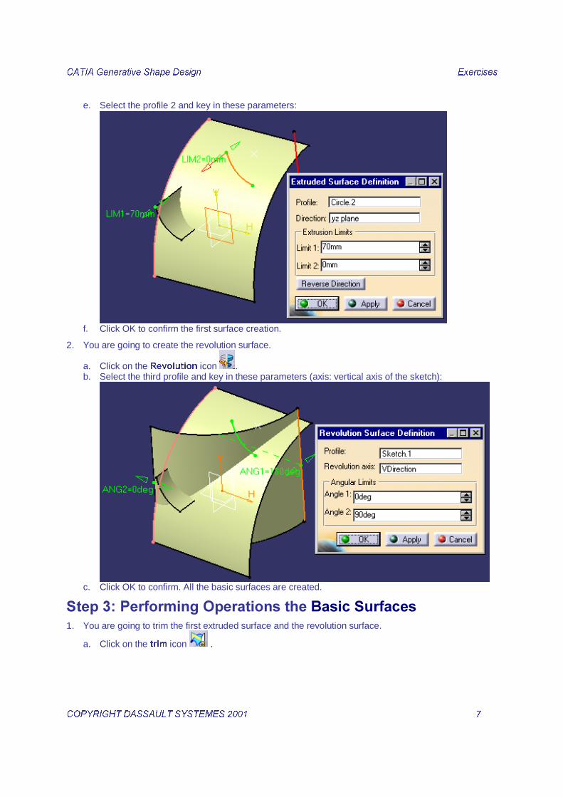
e. Select the profile 2 and key in these parameters:
f. Click OK to confirm the first surface creation.
2. You are going to create the revolution surface.
a. Click on the 5HYROXWLRQ icon . b. Select the third profile and key in these parameters (axis: vertical axis of the sketch):
c. Click OK to confirm. All the basic surfaces are created.
��� �!���������"������������������������1. You are going to trim the first extruded surface and the revolution surface.
a. Click on the WULP icon .
&$7,$�*HQHUDWLYH�6KDSH�'HVLJQ� � ([HUFLVHV��
&23<5,*+7�'$66$8/7�6<67(0(6������ � ��� �
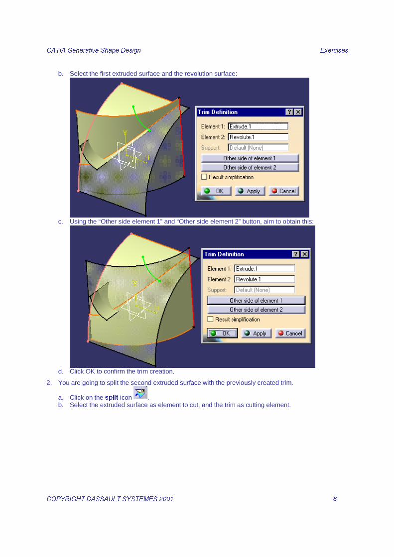
b. Select the first extruded surface and the revolution surface:
c. Using the “Other side element 1” and “Other side element 2” button, aim to obtain this:
d. Click OK to confirm the trim creation.
2. You are going to split the second extruded surface with the previously created trim.
a. Click on the VSOLW icon . b. Select the extruded surface as element to cut, and the trim as cutting element.

&$7,$�*HQHUDWLYH�6KDSH�'HVLJQ� � ([HUFLVHV��
&23<5,*+7�'$66$8/7�6<67(0(6������ � ��� �
c. Playing with the “Other side” button, aim to obtain this:
d. Click OK to confirm the split creation.
3. You are going to extrapolate the previously created split surface.
a. Click on the H[WUDSRODWH icon . b. Select the split surface lower boundary. c. Select the split surface. d. Select the “up to element” extrapolation type. e. Select the trim surface and activate the “Assemble result” button:
f. Click OK to confirm the extrapolate creation.
4. You are going to extrapolate the previously created extrapolate surface.
a. Click on the H[WUDSRODWH icon . b. Select the extrapolated surface higher boundary. c. Select the split surface. d. Select the “up to element” extrapolation type.

&$7,$�*HQHUDWLYH�6KDSH�'HVLJQ� � ([HUFLVHV��
&23<5,*+7�'$66$8/7�6<67(0(6������ � ���� �
e. Select the trim surface and activate the “Assemble result” button:
f. Click OK to confirm the second extrapolated surface creation.
5. You are going to trim the previously created extrapolate surface with the first created trim surface.
a. Click on the WULP icon . b. Select the last created extrapolated surface and the first created trim. c. Using the “Other side element 1” and “Other side element 2” button, aim to obtain this:
d. Click OK to confirm.
6. You are going to create a variable filet on the previously created trim.
a. Click on the YDULDEOH�UDGLXV�ILOOHW icon .

&$7,$�*HQHUDWLYH�6KDSH�'HVLJQ� � ([HUFLVHV��
&23<5,*+7�'$66$8/7�6<67(0(6������ � ���� �
b. Select this edge and key in the radius 10mm:
c. Double-click on the left radius value and key in 20mm:
d. Click OK to confirm. You get this:
e. Click OK to confirm the fillet creation:

&$7,$�*HQHUDWLYH�6KDSH�'HVLJQ� � ([HUFLVHV��
&23<5,*+7�'$66$8/7�6<67(0(6������ � ���� �
7. You are going to create an edge filet on the previously created surface.
a. Click on the HGJH�ILOOHW icon . b. Select this edge and key in the radius 5mm:
c. Click OK to confirm the fillet creation:

&$7,$�*HQHUDWLYH�6KDSH�'HVLJQ� � ([HUFLVHV��
&23<5,*+7�'$66$8/7�6<67(0(6������ � ���� �
8. You are going to create the symmetric surface and join the two surfaces.
a. Click on the V\PPHWU\ icon . b. Select the previously created surface as element to symmetrize and the YZ plane as reference:
c. Click OK to confirm.
d. Click on the MRLQ icon . e. Select the EdgeFillet.2 surface and the Symmetry.1 surface. f. Click OK to confirm the join operation.
9. You are going to create the symmetric surface from the previous join and join the two surfaces.
a. Click on the V\PPHWU\ icon .

&$7,$�*HQHUDWLYH�6KDSH�'HVLJQ� � ([HUFLVHV��
&23<5,*+7�'$66$8/7�6<67(0(6������ � ���� �
b. Select the previously created join as element to symmetrize and the ZX plane as reference:
c. Click OK to confirm.
d. Click on the MRLQ icon and select the Join.1 surface and the Symmetry.2 surface. e. Click OK to confirm the join creation.
The operations on the surfaces are all performed. You should get this:
���#�$����%�����&'�&���������&���������1. You are going to analyze the draft.
a. Click on the 'UDIW�$QDO\VLV icon .
b. Change to the customized view mode: c. Select the Join.2.

&$7,$�*HQHUDWLYH�6KDSH�'HVLJQ� � ([HUFLVHV��
&23<5,*+7�'$66$8/7�6<67(0(6������ � ���� �
d. Change the draft values to obtain:
e. Close the draft analysis color bar.
2. Then modify the draft angle. a. Double click on the Sketch.1 in the tree: you get in the sketch. b. Modify the line inclination from 90deg into 86deg:

&$7,$�*HQHUDWLYH�6KDSH�'HVLJQ� � ([HUFLVHV��
&23<5,*+7�'$66$8/7�6<67(0(6������ � ���� �
c. Exit the sketch. The part is automatically updated:
���(�"��������������&1. You are going to create a solid from the previously created surface.
a. Select Start / Mechanical Design / Part Design.
b. Select the Join.2.
c. Select the Thick Surface icon .

&$7,$�*HQHUDWLYH�6KDSH�'HVLJQ� � ([HUFLVHV��
&23<5,*+7�'$66$8/7�6<67(0(6������ � ���� �
d. Verify the Thick arrows pointing inward as shown below:
e. Key in 4mm in the First Offset Value field. f. Click OK to confirm the solid creation. g. Hide the Open Body containing all the surface elements.
2. Then you are going to split the solid to make its bottom face plane.

&$7,$�*HQHUDWLYH�6KDSH�'HVLJQ� � ([HUFLVHV��
&23<5,*+7�'$66$8/7�6<67(0(6������ � ���� �
a. Change the visualization mode to Wireframe:
b. Select the left view icon:
c. Zoom on the left bottom to check that the bottom of the part is no more plane.
d. Come back to a Shading visualization mode.
&$7,$�*HQHUDWLYH�6KDSH�'HVLJQ� � ([HUFLVHV��
&23<5,*+7�'$66$8/7�6<67(0(6������ � ���� �
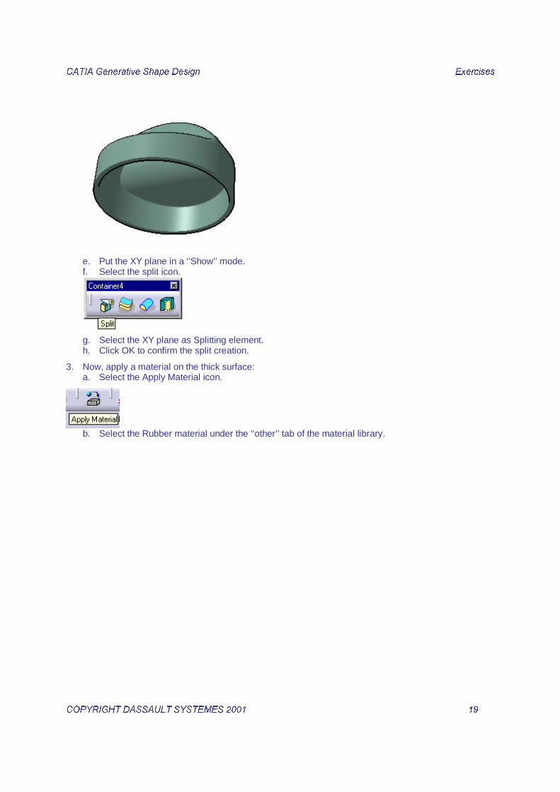
e. Put the XY plane in a ‘’Show’’ mode. f. Select the split icon.
g. Select the XY plane as Splitting element. h. Click OK to confirm the split creation.
3. Now, apply a material on the thick surface: a. Select the Apply Material icon.
b. Select the Rubber material under the ‘‘other’’ tab of the material library.

&$7,$�*HQHUDWLYH�6KDSH�'HVLJQ� � ([HUFLVHV��
&23<5,*+7�'$66$8/7�6<67(0(6������ � ���� �
c. Drag and drop it on the knob, click on OK to confirm.

&$7,$�*HQHUDWLYH�6KDSH�'HVLJQ� � ([HUFLVHV��
&23<5,*+7�'$66$8/7�6<67(0(6������ � ���� �
���������)�������������*+������Load the part called wireframe_recap_begin.CATPart from the ’’Companion’’ and save the part in the Students directory.
1. First you are going to create a maximum Z extremum on the left curve.
a. Click on the Extremum icon . b. The Extremum Definition Dialog box is opened, select the Maximum option. c. Select the Spline.1 d. Select the XY plane as Direction or Z axis by opening a contextual menu in the Direction field.

&$7,$�*HQHUDWLYH�6KDSH�'HVLJQ� � ([HUFLVHV��
&23<5,*+7�'$66$8/7�6<67(0(6������ � ���� �
e. Click OK to confirm the Z extremum creation.
2. You are going to create a minimum Z extremum on the right curve.
a. Click on the Extremum icon . b. The Extremum Definition Dialog box is opened, select the Maximum option. c. Select the Sketch.1. d. Select the XY plane as Direction or Z axis by opening a contextual menu in the Direction field.
e. Click OK to confirm the Z minimum creation.
3. You are going to Create a Connect Curve using the Extremums.
a. Click on the Connect Curve icon . b. Select the Spline.1 and the Extremum.1 to define the first curve.
&$7,$�*HQHUDWLYH�6KDSH�'HVLJQ� � ([HUFLVHV��
&23<5,*+7�'$66$8/7�6<67(0(6������ � ���� �
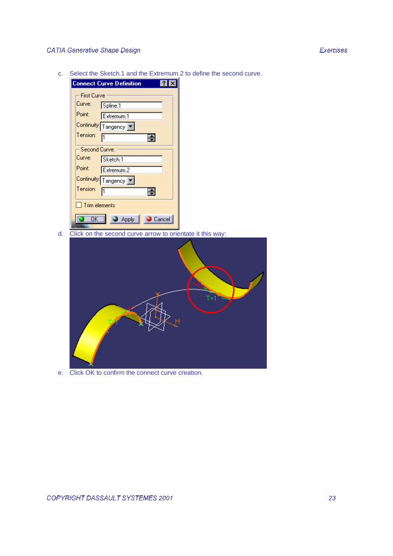
c. Select the Sketch.1 and the Extremum.2 to define the second curve.
d. Click on the second curve arrow to orientate it this way:
e. Click OK to confirm the connect curve creation.
&$7,$�*HQHUDWLYH�6KDSH�'HVLJQ� � ([HUFLVHV��
&23<5,*+7�'$66$8/7�6<67(0(6������ � ���� �

&$7,$�*HQHUDWLYH�6KDSH�'HVLJQ� � ([HUFLVHV��
&23<5,*+7�'$66$8/7�6<67(0(6������ � ���� �
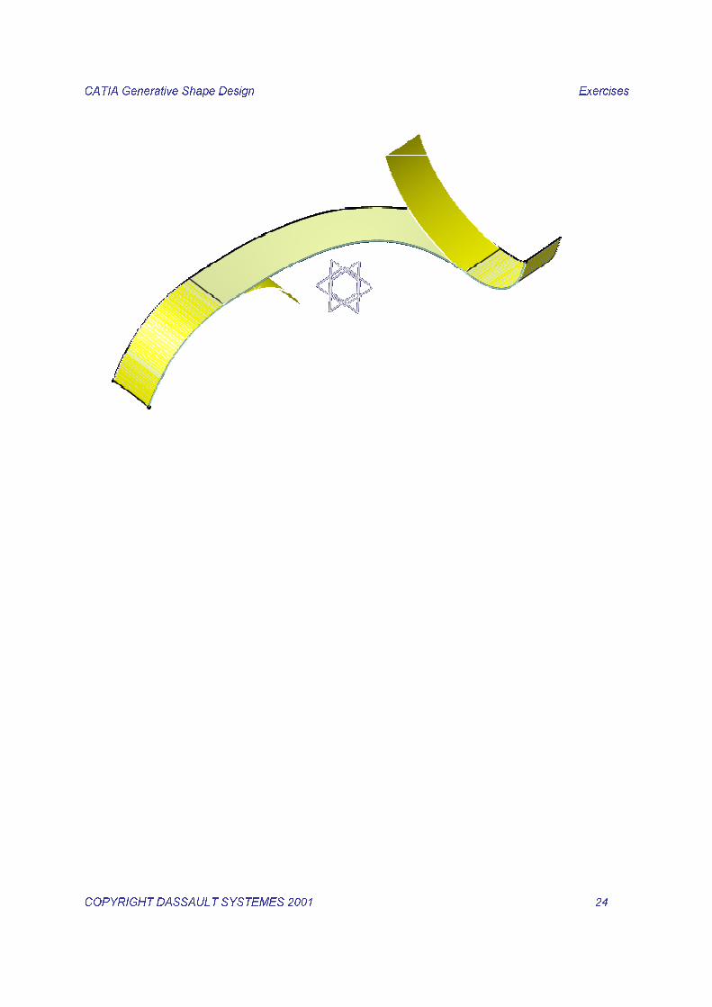
������)�������������*+������Load the part called surface_recap_begin.CATPart from the ’’Companion’’ and save the part in the Students directory.
1. First you are going to Offset 7 surfaces (1 mm.) from the inside of the Solid Clamp.
a. Double Click on the Offset icon . b. In the Offset Surface Definition dialog box enter an Offset value of 1mm. c. Select the first surface as shown
d. Click on OK to confirm the Offset surface creation. e. As you have double clicked on the icon, the Offset function is still active.Select the other six
surfaces with the same method.
&$7,$�*HQHUDWLYH�6KDSH�'HVLJQ� � ([HUFLVHV��
&23<5,*+7�'$66$8/7�6<67(0(6������ � ���� �
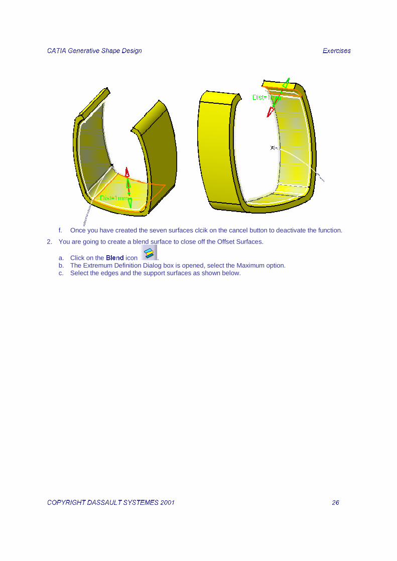
f. Once you have created the seven surfaces clcik on the cancel button to deactivate the function.
2. You are going to create a blend surface to close off the Offset Surfaces.
a. Click on the %OHQG icon . b. The Extremum Definition Dialog box is opened, select the Maximum option. c. Select the edges and the support surfaces as shown below.

&$7,$�*HQHUDWLYH�6KDSH�'HVLJQ� � ([HUFLVHV��
&23<5,*+7�'$66$8/7�6<67(0(6������ � ���� �
d. Click OK to confirm the blend creation.
&$7,$�*HQHUDWLYH�6KDSH�'HVLJQ� � ([HUFLVHV��
&23<5,*+7�'$66$8/7�6<67(0(6������ � ���� �
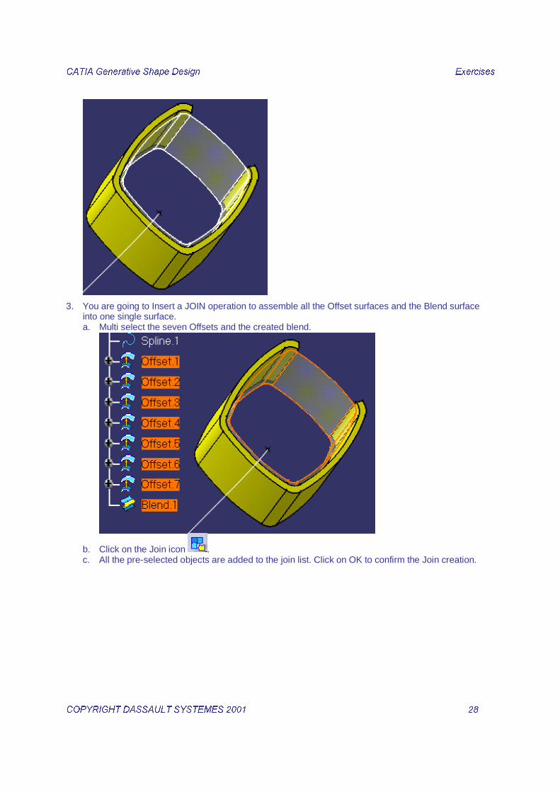
3. You are going to Insert a JOIN operation to assemble all the Offset surfaces and the Blend surface into one single surface. a. Multi select the seven Offsets and the created blend.
b. Click on the Join icon . c. All the pre-selected objects are added to the join list. Click on OK to confirm the Join creation.

&$7,$�*HQHUDWLYH�6KDSH�'HVLJQ� � ([HUFLVHV��
&23<5,*+7�'$66$8/7�6<67(0(6������ � ���� �
4. You are going to Extract a Boundary Curve from this JOIN surface.
a. Select the %RXQGDU\ icon . b. Select an edge of the Join as shown below.
c. Click on OK to confirm the Boundary curve creation.

&$7,$�*HQHUDWLYH�6KDSH�'HVLJQ� � ([HUFLVHV��
&23<5,*+7�'$66$8/7�6<67(0(6������ � ���� �
5. You are going to Create a Sweep Surface using the circular section curve (Output1) per parameters on the right.
a. Click on the sweep icon . b. In the Swept Surface Definition dialog box choose a /LQH�3URILOH�W\SH and ¶¶:LWK�UHIHUHQFH�
VXUIDFH¶¶ Subtype.
c. Select the Output1 circle as Guide curve1 and the Output1-Plane as Reference surface.

&$7,$�*HQHUDWLYH�6KDSH�'HVLJQ� � ([HUFLVHV��
&23<5,*+7�'$66$8/7�6<67(0(6������ � ���� �
d. Key in –88 degrees as Angle value and 100mm as Length 1
e. Click on OK to confirm the Swept Surface creation.
&$7,$�*HQHUDWLYH�6KDSH�'HVLJQ� � ([HUFLVHV��
&23<5,*+7�'$66$8/7�6<67(0(6������ � ���� �
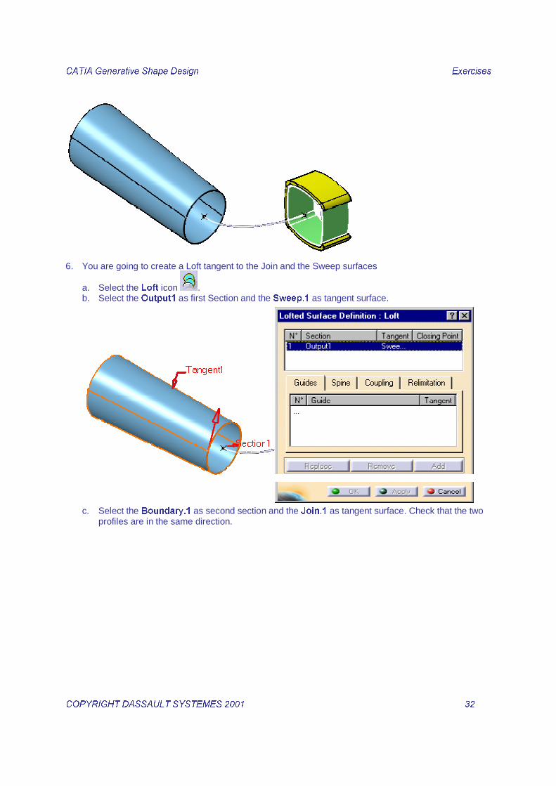
6. You are going to create a Loft tangent to the Join and the Sweep surfaces
a. Select the /RIW icon . b. Select the 2XWSXW��as first Section�and the�6ZHHS���as tangent surface.
c. Select the %RXQGDU\�� as second section�and the�-RLQ���as tangent surface. Check that the two
profiles are in the same direction.

&$7,$�*HQHUDWLYH�6KDSH�'HVLJQ� � ([HUFLVHV��
&23<5,*+7�'$66$8/7�6<67(0(6������ � ���� �
d. Click OK to confirm the loft creation.

&$7,$�*HQHUDWLYH�6KDSH�'HVLJQ� � ([HUFLVHV��
&23<5,*+7�'$66$8/7�6<67(0(6������ � ���� �
"��������)�������������*+������Load the part called dolphin_begin.CATPart from the ’’Companion’’ and save the part in the Students directory.
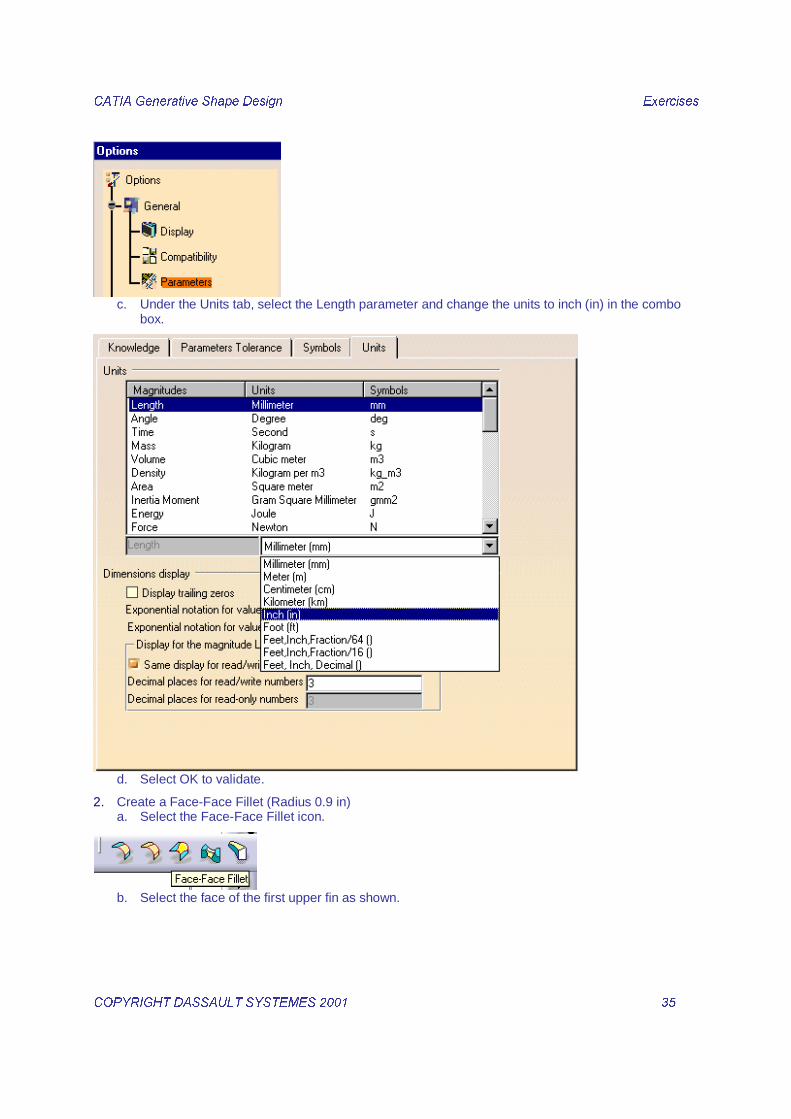
1. First you are going to change the Units to inches. a. Select Tools / Options.
b. Select *HQHUDO���3DUDPHWHUV in the left tree of the Option dialog box.
&$7,$�*HQHUDWLYH�6KDSH�'HVLJQ� � ([HUFLVHV��
&23<5,*+7�'$66$8/7�6<67(0(6������ � ���� �
c. Under the Units tab, select the Length parameter and change the units to inch (in) in the combo
box.
d. Select OK to validate.
2. Create a Face-Face Fillet (Radius 0.9 in) a. Select the Face-Face Fillet icon.
b. Select the�face of the first upper fin as shown.

&$7,$�*HQHUDWLYH�6KDSH�'HVLJQ� � ([HUFLVHV��
&23<5,*+7�'$66$8/7�6<67(0(6������ � ���� �
c. Select the face of the second upper fin as shown, change the radius fillet value if necessary.
d. Click on OK to confirm the Fillet creation.
3. Trim this fillet with all the side fins.
a. Click on the Trim icon . b. Select the created fillet.

&$7,$�*HQHUDWLYH�6KDSH�'HVLJQ� � ([HUFLVHV��
&23<5,*+7�'$66$8/7�6<67(0(6������ � ���� �
c. Select side fins.
d. Change the sides to cut.
e. Click on OK to confirm the Trim creation
&$7,$�*HQHUDWLYH�6KDSH�'HVLJQ� � ([HUFLVHV��
&23<5,*+7�'$66$8/7�6<67(0(6������ � ���� �
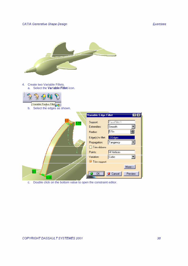
4. Create two Variable Fillets. a. Select the 9DULDEOH )LOOHW icon.
b. Select the edges as shown.
c. Double click on the bottom value to open the constraint editor.

&$7,$�*HQHUDWLYH�6KDSH�'HVLJQ� � ([HUFLVHV��
&23<5,*+7�'$66$8/7�6<67(0(6������ � ���� �
d. Change the value to 0.1 in then click on OK
e. Select the Top radius valueby a double click
f. Change its value to 0.03 in, then click OK

&$7,$�*HQHUDWLYH�6KDSH�'HVLJQ� � ([HUFLVHV��
&23<5,*+7�'$66$8/7�6<67(0(6������ � ���� �
g. Redo the same operations for the second edge.
h. Click on OK to confirm the Fillet creation.

&$7,$�*HQHUDWLYH�6KDSH�'HVLJQ� � ([HUFLVHV��
&23<5,*+7�'$66$8/7�6<67(0(6������ � ���� �
5. Create Tri-Tangent Fillets for the four side fins. a. Click on the tri-tangent fillet icon.
b. Select an top face of a fin as shown
c. Select the bottom face of the corresponding fin.

&$7,$�*HQHUDWLYH�6KDSH�'HVLJQ� � ([HUFLVHV��
&23<5,*+7�'$66$8/7�6<67(0(6������ � ���� �
d. Select the side face to remove.
e. Click OK to confirm the Fillet creation
f. Redo the same operations for the other fins

&$7,$�*HQHUDWLYH�6KDSH�'HVLJQ� � ([HUFLVHV��
&23<5,*+7�'$66$8/7�6<67(0(6������ � ���� �
6. Create a Shape Fillet with the nose and the Body. a. Select the Shape Fillet icon.
b. Select the Nose.
c. Select the previously created fillet.

&$7,$�*HQHUDWLYH�6KDSH�'HVLJQ� � ([HUFLVHV��
&23<5,*+7�'$66$8/7�6<67(0(6������ � ���� �
d. Change the direction of the fillet center.
e. Check the Trim support elements option and click on OK to confirm the fillet creation.
7. Create Edge Fillets between the Body and the front side fins. a. Select the Edge Fillet icon.

&$7,$�*HQHUDWLYH�6KDSH�'HVLJQ� � ([HUFLVHV��
&23<5,*+7�'$66$8/7�6<67(0(6������ � ���� �
b. Select the edges as shown.
c. Change the Radius value to 0.25 in.
d. Click on OK to confirm the Fillet creation.

&$7,$�*HQHUDWLYH�6KDSH�'HVLJQ� � ([HUFLVHV��
&23<5,*+7�'$66$8/7�6<67(0(6������ � ���� �

&$7,$�*HQHUDWLYH�6KDSH�'HVLJQ� � ([HUFLVHV��
&23<5,*+7�'$66$8/7�6<67(0(6������ � ���� �
$&�����&���,�)�������������*+������Load the part called dolphin_begin.CATPart from the ’’Companion’’ and save the part in the Students directory.
1. Create a Group ‘’Surface Model’’ leaving out the sketches a. Open a Contextual menu on the 2SHQBERG\�� and choose &UHDWH�*URXS���

&$7,$�*HQHUDWLYH�6KDSH�'HVLJQ� � ([HUFLVHV��
&23<5,*+7�'$66$8/7�6<67(0(6������ � ���� �
b. Click inside the Inputs field then multi-select the six sketches.
c. Rename the Group as ‘’Surface_Model’’.

&$7,$�*HQHUDWLYH�6KDSH�'HVLJQ� � ([HUFLVHV��
&23<5,*+7�'$66$8/7�6<67(0(6������ � ���� �
d. Click on the OK button to confirm the Group creation.
2. Rename the sketches, change the color and thickness. a. Select all the Sketches and show them.

&$7,$�*HQHUDWLYH�6KDSH�'HVLJQ� � ([HUFLVHV��
&23<5,*+7�'$66$8/7�6<67(0(6������ � ���� �
b. Select all the sketches and edit their properties.

&$7,$�*HQHUDWLYH�6KDSH�'HVLJQ� � ([HUFLVHV��
&23<5,*+7�'$66$8/7�6<67(0(6������ � ���� �
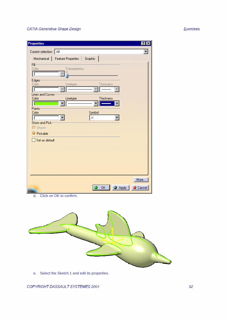
c. In the properties dialog box, select the Graphic tab then change the Color and Thickness of Lines
and Curves as shown below.
&$7,$�*HQHUDWLYH�6KDSH�'HVLJQ� � ([HUFLVHV��
&23<5,*+7�'$66$8/7�6<67(0(6������ � ���� �
d. Click on OK to confirm.
e. Select the Sketch.1 and edit its properties.

&$7,$�*HQHUDWLYH�6KDSH�'HVLJQ� � ([HUFLVHV��
&23<5,*+7�'$66$8/7�6<67(0(6������ � ���� �
f. Select the Feature Properties tab and rename it as Body.

&$7,$�*HQHUDWLYH�6KDSH�'HVLJQ� � ([HUFLVHV��
&23<5,*+7�'$66$8/7�6<67(0(6������ � ���� �
g. Click on OK to confirm.
h. Redo the same operation for the other sketches to obtain a tree as shown below.

&$7,$�*HQHUDWLYH�6KDSH�'HVLJQ� � ([HUFLVHV��
&23<5,*+7�'$66$8/7�6<67(0(6������ � ���� �
3. Change the Front_Top_Fin sketch. a. Double click on the Front_Top_fin sketch
b. Inside the Sketch seletc the top right contol point.
c. Drag it as shown below.

&$7,$�*HQHUDWLYH�6KDSH�'HVLJQ� � ([HUFLVHV��
&23<5,*+7�'$66$8/7�6<67(0(6������ � ���� �
d. Exit the Sketcher.
e. Update the part if the update mode is not on automatic.

&$7,$�*HQHUDWLYH�6KDSH�'HVLJQ� � ([HUFLVHV��
&23<5,*+7�'$66$8/7�6<67(0(6������ � ���� �

&$7,$�*HQHUDWLYH�6KDSH�'HVLJQ� � ([HUFLVHV��
&23<5,*+7�'$66$8/7�6<67(0(6������ � ���� �
!������������
�������������������������1. Insert a New Open Body
a. Select ,QVHUW in the Menu bar.
b. Select 2SHQ�%RG\ in the Insert Menu.

&$7,$�*HQHUDWLYH�6KDSH�'HVLJQ� � ([HUFLVHV��
&23<5,*+7�'$66$8/7�6<67(0(6������ � ���� �
c. Click on 2. in the Insert Open Body dialog box.
2. Select the created Open Body in the tree and edit its properties.

&$7,$�*HQHUDWLYH�6KDSH�'HVLJQ� � ([HUFLVHV��
&23<5,*+7�'$66$8/7�6<67(0(6������ � ���� �
3. Under the )HDWXUH�3URSHUWLHV tab rename the Open Body as %RWWOHB%RWWRP.
4. Create the Intersection Point. a. Select the ,QWHUVHFWLRQ icon.
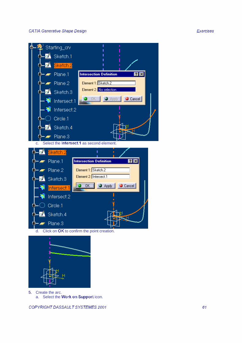
b. Select the 6NHWFK�� as first element
&$7,$�*HQHUDWLYH�6KDSH�'HVLJQ� � ([HUFLVHV��
&23<5,*+7�'$66$8/7�6<67(0(6������ � ���� �
c. Select the ,QWHUVHFW�� as second element.
d. Click on 2. to confirm the point creation.
5. Create the arc. a. Select the :RUN�RQ�6XSSRUW icon.

&$7,$�*HQHUDWLYH�6KDSH�'HVLJQ� � ([HUFLVHV��
&23<5,*+7�'$66$8/7�6<67(0(6������ � ���� �
b. Select the =;�SODQH as support.
c. Select the &LUFOH icon.
d. Choose ‘¶&HQWHU�DQG�3RLQW¶¶ as Circle type.
e. Open a contextual menu in the Center field and choose &UHDWH�3RLQW
f. In the Point Definition dialog box select a 3RLQW�RQ�SODQH type, complete the fields as shown
below then click on OK to confirm.

&$7,$�*HQHUDWLYH�6KDSH�'HVLJQ� � ([HUFLVHV��
&23<5,*+7�'$66$8/7�6<67(0(6������ � ���� �
g. Once you have created the center point, choose the ,QWHUVHFW�� as point then enter ±���DQG����
GHJUHHV�DV�6WDUW�DQG�(QG�DQJOH.
h. Click on 2. to confirm the circle creation.
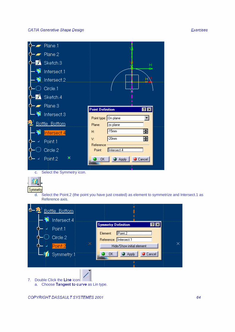
6. Create two bi tangent lines a. Select the 3RLQW icon. b. Choose ‘’On plane‘’ as point type, then complete the other fields as shown below.
&$7,$�*HQHUDWLYH�6KDSH�'HVLJQ� � ([HUFLVHV��
&23<5,*+7�'$66$8/7�6<67(0(6������ � ���� �
c. Select the Symmetry icon.
d. Select the Point.2 (the point you have just created) as element to symmetrize and Intersect.1 as
Reference axis.
7. Double Click the /LQH icon . a. Choose 7DQJHQW�WR�FXUYH as Lin type.

&$7,$�*HQHUDWLYH�6KDSH�'HVLJQ� � ([HUFLVHV��
&23<5,*+7�'$66$8/7�6<67(0(6������ � ���� �
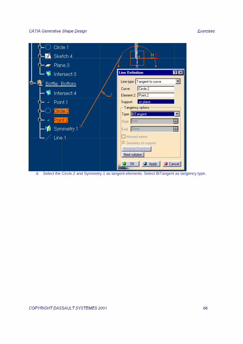
b. Select the Circle.2 and Point.2 as tangent elements. Select BiTangent as tangency type.
c. Click on OK to confirm the line creation.
&$7,$�*HQHUDWLYH�6KDSH�'HVLJQ� � ([HUFLVHV��
&23<5,*+7�'$66$8/7�6<67(0(6������ � ���� �
d. Select the Circle.2 and Symmetry.1 as tangent elements. Select BiTangent as tangency type.

&$7,$�*HQHUDWLYH�6KDSH�'HVLJQ� � ([HUFLVHV��
&23<5,*+7�'$66$8/7�6<67(0(6������ � ���� �
e. Click on OK to confirm the line creation.
8. Trim the lines and the circle. a. Select the 7ULP icon.
b. Select the Circle.2 and Line.1 as elements to trim and choose the side to keep as shown below.

&$7,$�*HQHUDWLYH�6KDSH�'HVLJQ� � ([HUFLVHV��
&23<5,*+7�'$66$8/7�6<67(0(6������ � ���� �
9. Redo the same operation with the Line.2 and the created Trim.1
10. Select the work on Support icon.
11. Click on Remove support to deactivate the work on support mode.
&$7,$�*HQHUDWLYH�6KDSH�'HVLJQ� � ([HUFLVHV��
&23<5,*+7�'$66$8/7�6<67(0(6������ � ���� �
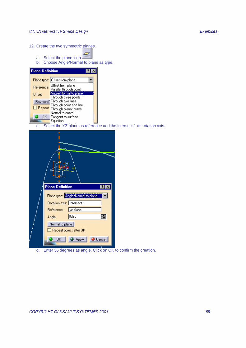
12. Create the two symmetric planes.
a. Select the plane icon . b. Choose Angle/Normal to plane as type.
c. Select the YZ plane as reference and the Intersect.1 as rotation axis.
d. Enter 36 degrees as angle. Click on OK to confirm the creation.

&$7,$�*HQHUDWLYH�6KDSH�'HVLJQ� � ([HUFLVHV��
&23<5,*+7�'$66$8/7�6<67(0(6������ � ���� �
13. Select the Symmetry icon.
� Select the created Plane.4 as element and the YZ plane as reference. Click on OK to confirm the
creation.
14. Create an explicit Sweep. a. Select the 6ZHHS icon.
b. Select the H[SOLFLW�6ZHHS icon.

&$7,$�*HQHUDWLYH�6KDSH�'HVLJQ� � ([HUFLVHV��
&23<5,*+7�'$66$8/7�6<67(0(6������ � ���� �
c. Select the 7ULP�� as profile.
d. Select the 6NHWFK�� as guide curve.

&$7,$�*HQHUDWLYH�6KDSH�'HVLJQ� � ([HUFLVHV��
&23<5,*+7�'$66$8/7�6<67(0(6������ � ���� �
e. Click on 2. to confirm the Sweep creation.

&$7,$�*HQHUDWLYH�6KDSH�'HVLJQ� � ([HUFLVHV��
&23<5,*+7�'$66$8/7�6<67(0(6������ � ���� �
15. Create an revolved surface. a. Select the 5HYROYH icon.
b. Select the 6NHWFK�� as profile.

&$7,$�*HQHUDWLYH�6KDSH�'HVLJQ� � ([HUFLVHV��
&23<5,*+7�'$66$8/7�6<67(0(6������ � ���� �
c. Select the ,QWHUVHFW�� as revolution axis and (90deg ; 90 deg) as Start and End angles. Click on
OK to confirm the surface creation.

&$7,$�*HQHUDWLYH�6KDSH�'HVLJQ� � ([HUFLVHV��
&23<5,*+7�'$66$8/7�6<67(0(6������ � ���� �
16. Assemble the created surfaces. a. Select the 7ULP icon.
b. Select the 5HYROXWH�� and the 6ZHHS�� you have just created and keep the sides as shown
below.

&$7,$�*HQHUDWLYH�6KDSH�'HVLJQ� � ([HUFLVHV��
&23<5,*+7�'$66$8/7�6<67(0(6������ � ���� �
c. Click on 2. to confirm the Trim creation.

&$7,$�*HQHUDWLYH�6KDSH�'HVLJQ� � ([HUFLVHV��
&23<5,*+7�'$66$8/7�6<67(0(6������ � ���� �
17. Create the variable fillet. a. Select the Variable Radius Fillet icon.
b. Select the 7 edges and enter the radiuses as shown below.
c. Click on 2. to confirm the fillet creation.
18. Create the complete bottom. a. Select the 6SOLW icon then the EdgeFillet.1 you have just created and the Plane.4 and keep the
side as shown.

&$7,$�*HQHUDWLYH�6KDSH�'HVLJQ� � ([HUFLVHV��
&23<5,*+7�'$66$8/7�6<67(0(6������ � ���� �
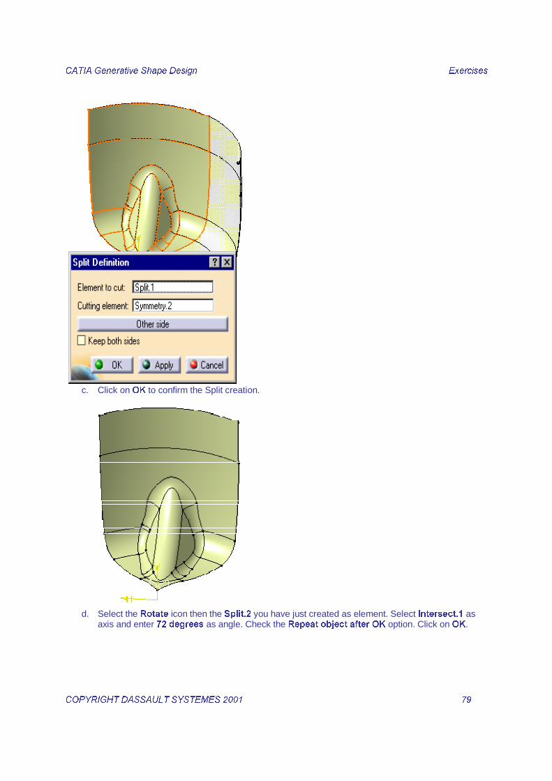
b. Redo the same operation with the Plane Symmetry.2
&$7,$�*HQHUDWLYH�6KDSH�'HVLJQ� � ([HUFLVHV��
&23<5,*+7�'$66$8/7�6<67(0(6������ � ���� �
c. Click on 2. to confirm the Split creation.
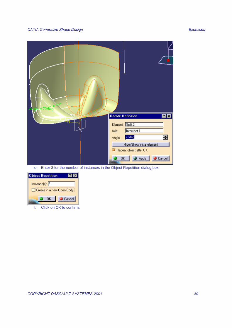
d. Select the 5RWDWH icon then the 6SOLW�� you have just created as element. Select ,QWHUVHFW�� as
axis and enter ���GHJUHHV as angle. Check the 5HSHDW�REMHFW�DIWHU�2. option. Click on 2..
&$7,$�*HQHUDWLYH�6KDSH�'HVLJQ� � ([HUFLVHV��
&23<5,*+7�'$66$8/7�6<67(0(6������ � ���� �
e. Enter 3 for the number of instances in the Object Repetition dialog box.
f. Click on OK to confirm.

&$7,$�*HQHUDWLYH�6KDSH�'HVLJQ� � ([HUFLVHV��
&23<5,*+7�'$66$8/7�6<67(0(6������ � ���� �
19. Select the Join icon the Split.2 and all the rotated instances.
20. Rename the Join as %RWWOHB%RWWRP�

&$7,$�*HQHUDWLYH�6KDSH�'HVLJQ� � ([HUFLVHV��
&23<5,*+7�'$66$8/7�6<67(0(6������ � ���� �
�������������&���������1. Insert a new Open Body.
2. Edit the Properties of the new Open body then under the Feature Properties tab rename it as %RWWOHB%RG\.

&$7,$�*HQHUDWLYH�6KDSH�'HVLJQ� � ([HUFLVHV��
&23<5,*+7�'$66$8/7�6<67(0(6������ � ���� �
3. Double Click the 3DUDOOHO�&XUYH icon.
a. Select the 6NHWFK�� as Curve. Select the =;�SODQH as Support. Enter an Offset value of ��PP.
Click on OK to confirm.
b. Redo the same operation with the same entities but in the Reverse direction.

&$7,$�*HQHUDWLYH�6KDSH�'HVLJQ� � ([HUFLVHV��
&23<5,*+7�'$66$8/7�6<67(0(6������ � ���� �
c. Click on OK to confirm.
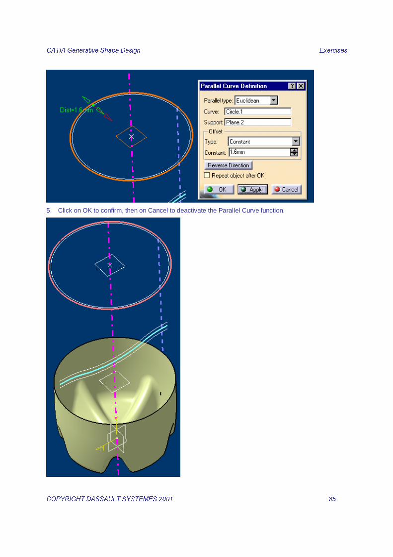
4. Select the &LUFOH�� as Curve. Select the 3ODQH�� as Support. Enter an Offset value of ����PP�
&$7,$�*HQHUDWLYH�6KDSH�'HVLJQ� � ([HUFLVHV��
&23<5,*+7�'$66$8/7�6<67(0(6������ � ���� �
5. Click on OK to confirm, then on Cancel to deactivate the Parallel Curve function.
&$7,$�*HQHUDWLYH�6KDSH�'HVLJQ� � ([HUFLVHV��
&23<5,*+7�'$66$8/7�6<67(0(6������ � ���� �
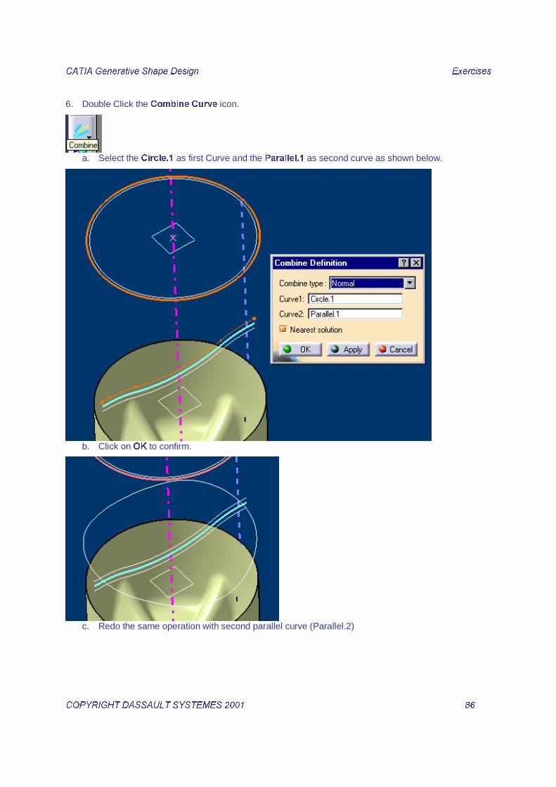
6. Double Click the &RPELQH &XUYH icon.
a. Select the &LUFOH�� as first Curve and the 3DUDOOHO�� as second curve as shown below.
b. Click on 2. to confirm.
c. Redo the same operation with second parallel curve (Parallel.2)

&$7,$�*HQHUDWLYH�6KDSH�'HVLJQ� � ([HUFLVHV��
&23<5,*+7�'$66$8/7�6<67(0(6������ � ���� �
7. Create another combined curve between the 6NHWFK��. and the 3DUDOOHO��.
8. Click on 2. to confirm, then on Cancel to deactivate the function.

&$7,$�*HQHUDWLYH�6KDSH�'HVLJQ� � ([HUFLVHV��
&23<5,*+7�'$66$8/7�6<67(0(6������ � ���� �
9. Create a sweep surface on the combined curves.
a. Select the Sweep icon . b. Select Circular Implicit Swept surface type and Three guides subtype.

&$7,$�*HQHUDWLYH�6KDSH�'HVLJQ� � ([HUFLVHV��
&23<5,*+7�'$66$8/7�6<67(0(6������ � ���� �
c. Select the three combined curves as Guide curves.
d. Click on 2. to confirm.

&$7,$�*HQHUDWLYH�6KDSH�'HVLJQ� � ([HUFLVHV��
&23<5,*+7�'$66$8/7�6<67(0(6������ � ���� �
10. Create three instances of the swept surface using a Translate.
a. Select the 7UDQVODWH icon . b. Select the 6ZHHS�� (the sweep you have just created) as Element and the Z axis as direction.
c. Open a contextual menu in the Distance field then choose Edit formula.

&$7,$�*HQHUDWLYH�6KDSH�'HVLJQ� � ([HUFLVHV��
&23<5,*+7�'$66$8/7�6<67(0(6������ � ���� �
d. In the formula Editor dialog box, select the formula field. In the tree select the 2IIVHW parameter
under the 3ODQH�� feature, then key in µ¶���¶¶ after the inserted string. Click on OK.
e. The distance formula has been added in the Translate definiton dialog box and a preview of the
result is displayed.
f. Check the Repeat object after OK option and click on OK.

&$7,$�*HQHUDWLYH�6KDSH�'HVLJQ� � ([HUFLVHV��
&23<5,*+7�'$66$8/7�6<67(0(6������ � ���� �
g. Enter 2 as number of instances in the Object Repetition dialog box.
h. Click on OK to confirm.

&$7,$�*HQHUDWLYH�6KDSH�'HVLJQ� � ([HUFLVHV��
&23<5,*+7�'$66$8/7�6<67(0(6������ � ���� �
11. Join the created surfaces. a. Multi select the Sweep.2 and all the created translated surfaces.
b. Select the -RLQ icon.
c. Click on OK to confirm the Join creation

&$7,$�*HQHUDWLYH�6KDSH�'HVLJQ� � ([HUFLVHV��
&23<5,*+7�'$66$8/7�6<67(0(6������ � ���� �
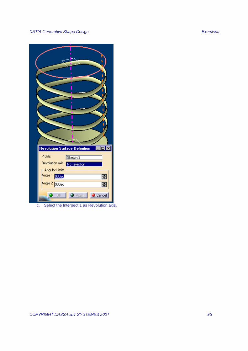
12. Create a Revolve surface using the Sketch.3
a. Select the Revolve icon . b. Select the Sketch.3 as profile.
&$7,$�*HQHUDWLYH�6KDSH�'HVLJQ� � ([HUFLVHV��
&23<5,*+7�'$66$8/7�6<67(0(6������ � ���� �
c. Select the Intersect.1 as Revolution axis.

&$7,$�*HQHUDWLYH�6KDSH�'HVLJQ� � ([HUFLVHV��
&23<5,*+7�'$66$8/7�6<67(0(6������ � ���� �
d. Enter (180 deg ; 180 deg) as angular limits.
e. Click on OK to confirm.
&$7,$�*HQHUDWLYH�6KDSH�'HVLJQ� � ([HUFLVHV��
&23<5,*+7�'$66$8/7�6<67(0(6������ � ���� �
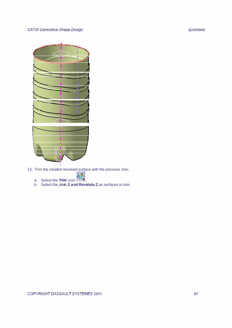
13. Trim the created revolved surface with the previous Join.
a. Select the 7ULP icon . b. Select the -RLQ���DQG�5HYROXWH�� as surfaces to trim.

&$7,$�*HQHUDWLYH�6KDSH�'HVLJQ� � ([HUFLVHV��
&23<5,*+7�'$66$8/7�6<67(0(6������ � ���� �
c. Configurate the trim using ‘’Other side of element’’ button to obtain:

&$7,$�*HQHUDWLYH�6KDSH�'HVLJQ� � ([HUFLVHV��
&23<5,*+7�'$66$8/7�6<67(0(6������ � ���� �
d. Click on OK to confirm the Trim creation.
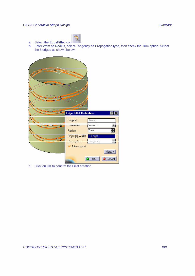
14. Create a EdgeFillet on the created Trim.
&$7,$�*HQHUDWLYH�6KDSH�'HVLJQ� � ([HUFLVHV��
&23<5,*+7�'$66$8/7�6<67(0(6������ � ����� �
a. Select the (GJH)LOOHW icon . b. Enter 2mm as Radius, select Tangency as Propagation type, then check the Trim option. Select
the 8 edges as shown below.
c. Click on OK to confirm the Fillet creation.

&$7,$�*HQHUDWLYH�6KDSH�'HVLJQ� � ([HUFLVHV��
&23<5,*+7�'$66$8/7�6<67(0(6������ � ����� �
d. Rename the created fillet as ‘’Bottle_Body’’

&$7,$�*HQHUDWLYH�6KDSH�'HVLJQ� � ([HUFLVHV��
&23<5,*+7�'$66$8/7�6<67(0(6������ � ����� �
��� ����������,1. Insert a new Open Body.

&$7,$�*HQHUDWLYH�6KDSH�'HVLJQ� � ([HUFLVHV��
&23<5,*+7�'$66$8/7�6<67(0(6������ � ����� �
2. Edit the Properties of the new Open Body then under the Feature Properties tab rename it as Bottleneck.
3. Create the point between and the parallel plane.

&$7,$�*HQHUDWLYH�6KDSH�'HVLJQ� � ([HUFLVHV��
&23<5,*+7�'$66$8/7�6<67(0(6������ � ����� �
a. Select the�3RLQW�icon � b. Select %HWZHHQ as Point type then select the ,QWHUVHFW���as first point�DQG�,QWHUVHFW�� as second
point. Enter a UDWLR of ��� then click on OK.
4. Select the�3ODQH�icon � a. Select 3DUDOOHO�WKURXJK�SRLQW plane type. Select the 3ODQH�� as UHIHUHQFH and the just created
3RLQW�� as SRLQW. Click on 2. to confirm the point creation.

&$7,$�*HQHUDWLYH�6KDSH�'HVLJQ� � ([HUFLVHV��
&23<5,*+7�'$66$8/7�6<67(0(6������ � ����� �
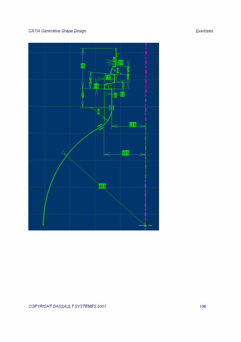
5. Create the Sketch.5
a. Select the�6NHWFK�icon � b. Select the ZX plane as sketch support� c. Draw on the fly the following profile.

&$7,$�*HQHUDWLYH�6KDSH�'HVLJQ� � ([HUFLVHV��
&23<5,*+7�'$66$8/7�6<67(0(6������ � ����� �
d. Select the�&RQVWUDLQW�icon�
e. Select the�Center of the lower arc then the ,QWHUVHFW�� point, open a contextual menu then
choose a coincidence constraint.
&$7,$�*HQHUDWLYH�6KDSH�'HVLJQ� � ([HUFLVHV��
&23<5,*+7�'$66$8/7�6<67(0(6������ � ����� �
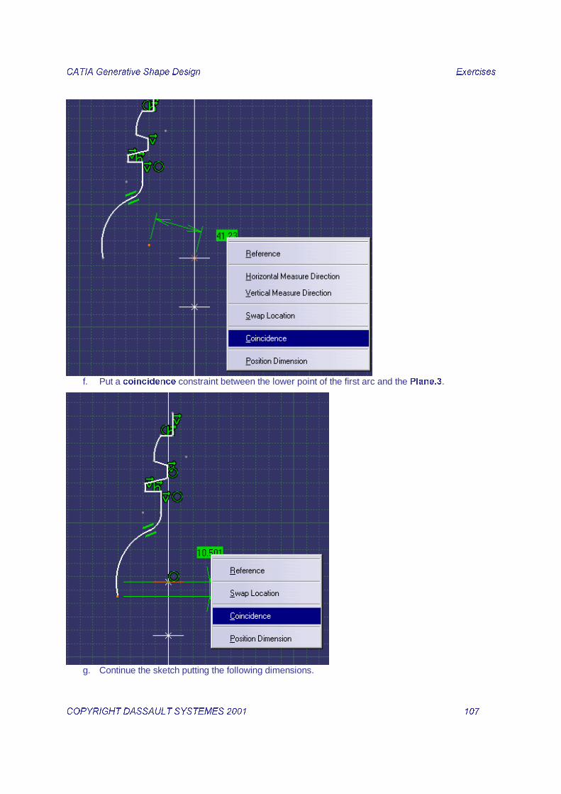
f. Put a FRLQFLGHQFH constraint between the lower point of the first arc and the 3ODQH��.
g. Continue the sketch putting the following dimensions.
&$7,$�*HQHUDWLYH�6KDSH�'HVLJQ� � ([HUFLVHV��
&23<5,*+7�'$66$8/7�6<67(0(6������ � ����� �

&$7,$�*HQHUDWLYH�6KDSH�'HVLJQ� � ([HUFLVHV��
&23<5,*+7�'$66$8/7�6<67(0(6������ � ����� �
h. Exit the Sketcher.

&$7,$�*HQHUDWLYH�6KDSH�'HVLJQ� � ([HUFLVHV��
&23<5,*+7�'$66$8/7�6<67(0(6������ � ����� �
6. Create the Extremums. a. Select the�([WUHPXP�icon�
b. Select a Maximum type, the just created�6NHWFK���as element and the Z axis as direction. Click
on OK to confirm the point creation.

&$7,$�*HQHUDWLYH�6KDSH�'HVLJQ� � ([HUFLVHV��
&23<5,*+7�'$66$8/7�6<67(0(6������ � ����� �
c. Create the minimum extremum on the same profile.
d. Click on OK to confirm the point creation.

&$7,$�*HQHUDWLYH�6KDSH�'HVLJQ� � ([HUFLVHV��
&23<5,*+7�'$66$8/7�6<67(0(6������ � ����� �
7. Create a Revolution surface with the sketch.
a. Select the 5HYROYH icon . b. Select the 6NHWFK���as SURILOH and the ,QWHUVHFW�� as 5HYROXWLRQ D[LV.

&$7,$�*HQHUDWLYH�6KDSH�'HVLJQ� � ([HUFLVHV��
&23<5,*+7�'$66$8/7�6<67(0(6������ � ����� �
c. Click on OK to confirm the surface creation.
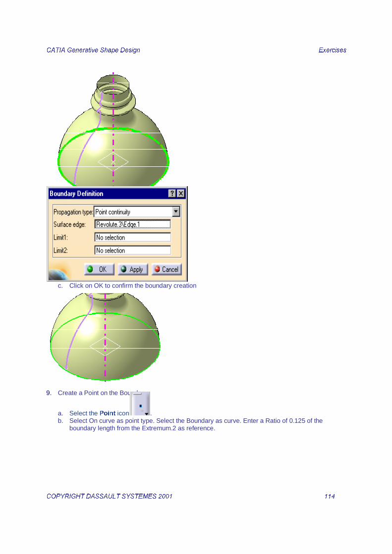
8. Create a Boundary on the Revolution surface.
a. Select the %RXQGDU\ icon . b. Select the lower edge of the Revolution surface as shown below.
&$7,$�*HQHUDWLYH�6KDSH�'HVLJQ� � ([HUFLVHV��
&23<5,*+7�'$66$8/7�6<67(0(6������ � ����� �
c. Click on OK to confirm the boundary creation
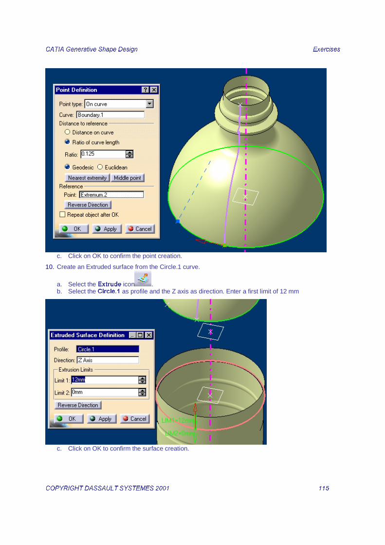
9. Create a Point on the Boundary.
a. Select the 3RLQW icon . b. Select On curve as point type. Select the Boundary as curve. Enter a Ratio of 0.125 of the
boundary length from the Extremum.2 as reference.
&$7,$�*HQHUDWLYH�6KDSH�'HVLJQ� � ([HUFLVHV��
&23<5,*+7�'$66$8/7�6<67(0(6������ � ����� �
c. Click on OK to confirm the point creation.
10. Create an Extruded surface from the Circle.1 curve.
a. Select the ([WUXGH icon . b. Select the &LUFOH�� as profile and the Z axis as direction. Enter a first limit of 12 mm
c. Click on OK to confirm the surface creation.

&$7,$�*HQHUDWLYH�6KDSH�'HVLJQ� � ([HUFLVHV��
&23<5,*+7�'$66$8/7�6<67(0(6������ � ����� �
11. Create the boundary of the extruded surface.
a. Select the %RXQGDU\ icon . b. Select the upper edge of the extrude.1 surface.

&$7,$�*HQHUDWLYH�6KDSH�'HVLJQ� � ([HUFLVHV��
&23<5,*+7�'$66$8/7�6<67(0(6������ � ����� �
c. Click on OK to confirm the Boundary creation.
12. Create the intermediate circle.
a. Select the &LUFOH icon . b. Choose Center and radius as Circle type. Select the Point.3 as center, the Plane.5 as Support
and enter a radius of 35mm.

&$7,$�*HQHUDWLYH�6KDSH�'HVLJQ� � ([HUFLVHV��
&23<5,*+7�'$66$8/7�6<67(0(6������ � ����� �
c. Click on OK to confirm the circle creation.
13. Create the projected points.
a. Select the 3URMHFWLRQ icon . b. Select the ([WUHPXP���as SURMHFWHG HOHPHQW and the &LUFOH�� you have just created as
VXSSRUW then click on 2..
c. Redo the same operation to create a projected point on the Boundary.2

&$7,$�*HQHUDWLYH�6KDSH�'HVLJQ� � ([HUFLVHV��
&23<5,*+7�'$66$8/7�6<67(0(6������ � ����� �
d. Click on OK to confirm the point creation.
14. Create the Loft.
a. Select the /RIW icon . b. Select the %RXQGDU\�� as first section then the UHYROXWLRQ surface as tangent and the
([WUHPXP�� as Closing point. c. Select the &LUFOH�� as second section then the 3URMHFW�� as Closing point. d. Select the %RXQGDU\�� as third section then the H[WUXGH surface as tangent and the 3URMHFW�� as
Closing point.

&$7,$�*HQHUDWLYH�6KDSH�'HVLJQ� � ([HUFLVHV��
&23<5,*+7�'$66$8/7�6<67(0(6������ � ����� �
e. Click on OK to confirm the surface creation.

&$7,$�*HQHUDWLYH�6KDSH�'HVLJQ� � ([HUFLVHV��
&23<5,*+7�'$66$8/7�6<67(0(6������ � ����� �
15. Create two lines on the loft.
a. Select the /LQH icon . b. Choose $QJOH�1RUPDO�WR�FXUYH as Line type. Select the %RXQGDU\�� as curve and the /RIW�� as
Support. Select the ([WUHPXP�� as Starting Point. Enter ±���GHJ as Angle and ����PP as End length. Check the *HRPHWU\�RQ�VXSSRUW option.
c. Click on OK to confirm the line creation.

&$7,$�*HQHUDWLYH�6KDSH�'HVLJQ� � ([HUFLVHV��
&23<5,*+7�'$66$8/7�6<67(0(6������ � ����� �
d. Create a line with same characteristics but starting from the 3RLQW��

&$7,$�*HQHUDWLYH�6KDSH�'HVLJQ� � ([HUFLVHV��
&23<5,*+7�'$66$8/7�6<67(0(6������ � ����� �
e. Click on OK to confirm the Line creation.
16. Create two Boundaries limited by the two lines. a. Hide the two previous boundary curves.
b. Select the Boundary icon . c. Select the lower edge of the revolution surface then relimit the boundary with the two previous
lines.
d. Click on OK to confirm the Boundary creation.

&$7,$�*HQHUDWLYH�6KDSH�'HVLJQ� � ([HUFLVHV��
&23<5,*+7�'$66$8/7�6<67(0(6������ � ����� �
e. Redo the same operation with upper edge of the Extruded surface.
f. Click on OK to confirm the boundary creation.
17. Create a Fill surface with the created lines.
18. Hide the Loft.
19. Select the Fill surface icon . a. Select the four previous lines as shown below using the revolution and extruded surfaces as
supports for the boundary curves.

&$7,$�*HQHUDWLYH�6KDSH�'HVLJQ� � ([HUFLVHV��
&23<5,*+7�'$66$8/7�6<67(0(6������ � ����� �
b. Click on OK to confirm the surface creation.
20. Rotate the fill surface around the Intersect.1.
a. Select the Rotate icon . b. Select the )LOO�� as Element, ,QWHUVHFW�� as axis then ���GHJUHHV as angle. Check the 5HSHDW�
REMHFW�DIWHU�2.. Click on 2..

&$7,$�*HQHUDWLYH�6KDSH�'HVLJQ� � ([HUFLVHV��
&23<5,*+7�'$66$8/7�6<67(0(6������ � ����� �
c. Enter � for the number of instances to repeat.
d. Click on 2. to confirm the surfaces creation.

&$7,$�*HQHUDWLYH�6KDSH�'HVLJQ� � ([HUFLVHV��
&23<5,*+7�'$66$8/7�6<67(0(6������ � ����� �
21. Analyse the connections between the created surfaces a. Multi-select the )LOO�� and the 5RWDWH��.

&$7,$�*HQHUDWLYH�6KDSH�'HVLJQ� � ([HUFLVHV��
&23<5,*+7�'$66$8/7�6<67(0(6������ � ����� �
22. Select the &RQQHFW�&KHFNHU icon .
23. Select the Information display mode to check that there is a gap between the two surfaces.

&$7,$�*HQHUDWLYH�6KDSH�'HVLJQ� � ([HUFLVHV��
&23<5,*+7�'$66$8/7�6<67(0(6������ � ����� �
24. Fill the gap between the rotated surfaces.
a. Select the Healing icon . b. Select the Fill.1 and all the rotaed surfaces. Enter a Merging distance of 0.5 mm.

&$7,$�*HQHUDWLYH�6KDSH�'HVLJQ� � ([HUFLVHV��
&23<5,*+7�'$66$8/7�6<67(0(6������ � ����� �
c. Click on OK to confirm the surface creation.
d. Select the Join icon . e. Select the created Healing.1, the Extrude.1 and the Revolute.3

&$7,$�*HQHUDWLYH�6KDSH�'HVLJQ� � ([HUFLVHV��
&23<5,*+7�'$66$8/7�6<67(0(6������ � ����� �
f. Click on OK to confirm the surface creation.
25. Rename the Join as Body_Style.

&$7,$�*HQHUDWLYH�6KDSH�'HVLJQ� � ([HUFLVHV��
&23<5,*+7�'$66$8/7�6<67(0(6������ � ����� �
���#�$�����������������&���1. Insert a new Open Body
2. Rename the new Open Body as Bootle_Assembled.

&$7,$�*HQHUDWLYH�6KDSH�'HVLJQ� � ([HUFLVHV��
&23<5,*+7�'$66$8/7�6<67(0(6������ � ����� �
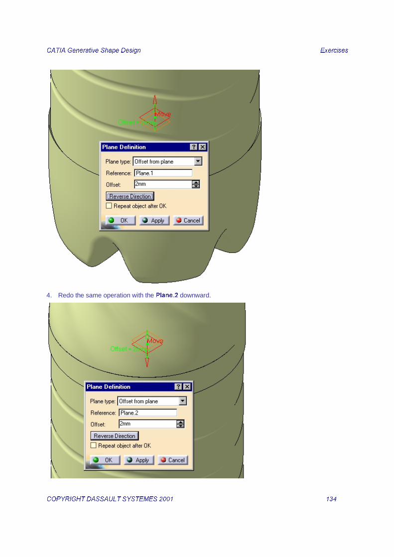
3. Create two Offset planes. a. Select Plane.1 and Plane.2 in the tree and Show them.
b. Select the 3ODQH icon . c. Choose 2IIVHW�IURP�SODQH as Plane type, select the 3ODQH�� as reference then enter an RIIVHW�
YDOXH�RI��PP. Orient the direction XSZDUG. Click on 2. to confirm the plane creation.
&$7,$�*HQHUDWLYH�6KDSH�'HVLJQ� � ([HUFLVHV��
&23<5,*+7�'$66$8/7�6<67(0(6������ � ����� �
4. Redo the same operation with the 3ODQH�� downward.

&$7,$�*HQHUDWLYH�6KDSH�'HVLJQ� � ([HUFLVHV��
&23<5,*+7�'$66$8/7�6<67(0(6������ � ����� �
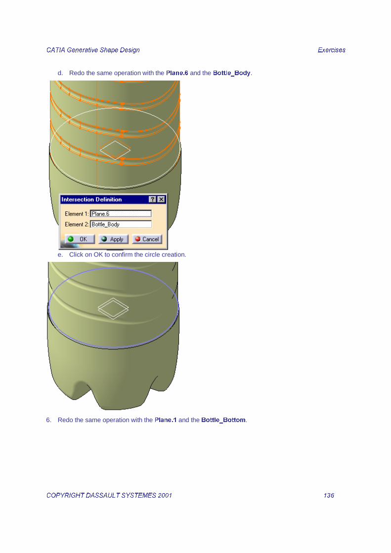
5. Create two circles on the Offset planes.
a. Select the ,QWHUVHFWLRQ icon . b. Select the 3ODQH�� and the %RWWOHB%RG\ as elements to intersect.
c. Click on OK to confirm the circle creation.
&$7,$�*HQHUDWLYH�6KDSH�'HVLJQ� � ([HUFLVHV��
&23<5,*+7�'$66$8/7�6<67(0(6������ � ����� �
d. Redo the same operation with the 3ODQH�� and the %RWWOHB%RG\.
e. Click on OK to confirm the circle creation.
6. Redo the same operation with the 3ODQH�� and the %RWWOHB%RWWRP.

&$7,$�*HQHUDWLYH�6KDSH�'HVLJQ� � ([HUFLVHV��
&23<5,*+7�'$66$8/7�6<67(0(6������ � ����� �
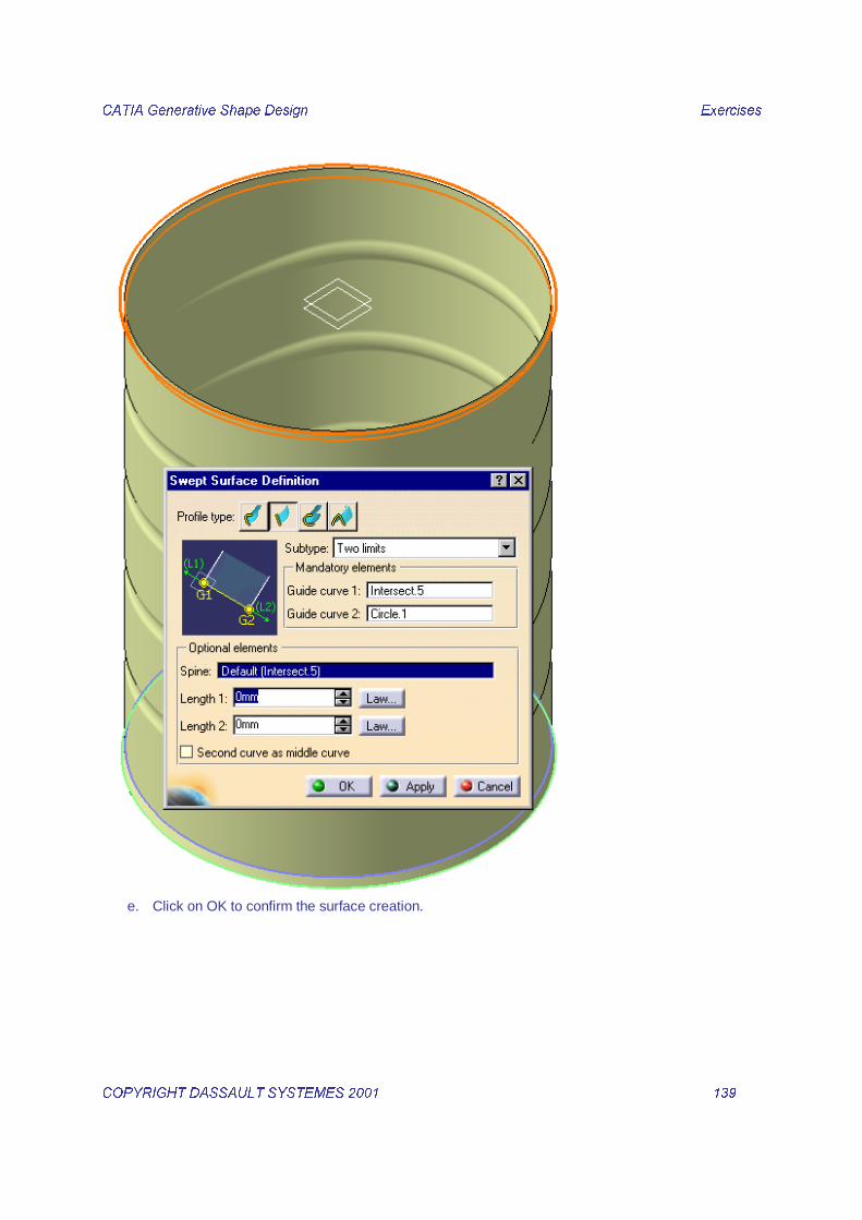
7. Create two swept surfaces.
a. Select the 6ZHHS icon . b. Choose an ,PSOLFLW�OLQHDU�SURILOH as profile type and 7ZR�OLPLWV as subtype. Select the
,QWHUVHFW�� and ,QWHUVHFW�� as guide curve.

&$7,$�*HQHUDWLYH�6KDSH�'HVLJQ� � ([HUFLVHV��
&23<5,*+7�'$66$8/7�6<67(0(6������ � ����� �
c. Click on 2. to confirm the surface creation.
d. Choose an ,PSOLFLW�OLQHDU�SURILOH as profile type and 7ZR�OLPLWV as subtype. Select the
,QWHUVHFW�� and &LUFOH�� as guide curve.
&$7,$�*HQHUDWLYH�6KDSH�'HVLJQ� � ([HUFLVHV��
&23<5,*+7�'$66$8/7�6<67(0(6������ � ����� �
e. Click on OK to confirm the surface creation.

&$7,$�*HQHUDWLYH�6KDSH�'HVLJQ� � ([HUFLVHV��
&23<5,*+7�'$66$8/7�6<67(0(6������ � ����� �
8. Trim the created surfaces with the previous bodies.
a. Select the 7ULP icon . b. Select the %RWWOHB%RG\ and the just created 6ZHHS�� as elements to sweep.

&$7,$�*HQHUDWLYH�6KDSH�'HVLJQ� � ([HUFLVHV��
&23<5,*+7�'$66$8/7�6<67(0(6������ � ����� �
c. Click on OK to create the new surface.
9. Redo a Trim operation between the %RG\B6W\OH and the just created 7ULP��.

&$7,$�*HQHUDWLYH�6KDSH�'HVLJQ� � ([HUFLVHV��
&23<5,*+7�'$66$8/7�6<67(0(6������ � ����� �
10. Redo a Trim operation between the %RWWOHB%RWWOH and the 6ZHHS���

&$7,$�*HQHUDWLYH�6KDSH�'HVLJQ� � ([HUFLVHV��
&23<5,*+7�'$66$8/7�6<67(0(6������ � ����� �

&$7,$�*HQHUDWLYH�6KDSH�'HVLJQ� � ([HUFLVHV��
&23<5,*+7�'$66$8/7�6<67(0(6������ � ����� �
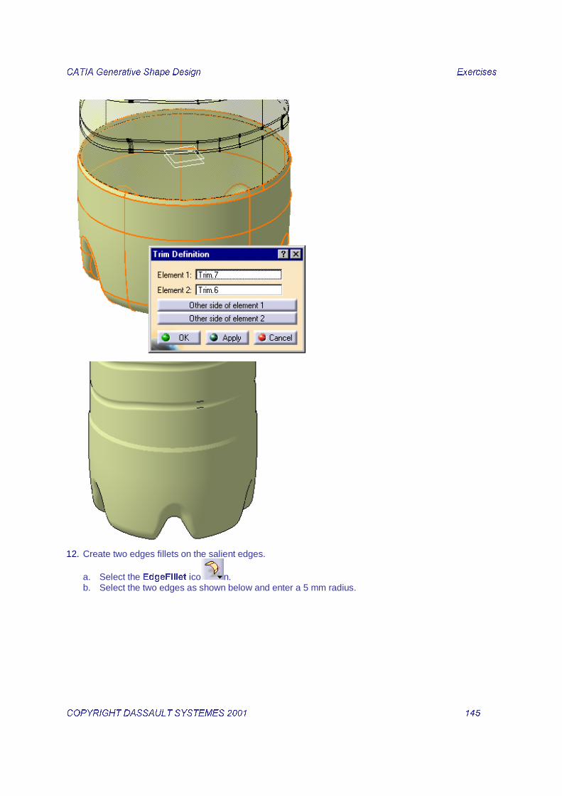
11. Redo a Trim operation between the just created 7ULP�� and 7ULP���
&$7,$�*HQHUDWLYH�6KDSH�'HVLJQ� � ([HUFLVHV��
&23<5,*+7�'$66$8/7�6<67(0(6������ � ����� �
12. Create two edges fillets on the salient edges.
a. Select the (GJH)LOOHW ico n. b. Select the two edges as shown below and enter a 5 mm radius.

&$7,$�*HQHUDWLYH�6KDSH�'HVLJQ� � ([HUFLVHV��
&23<5,*+7�'$66$8/7�6<67(0(6������ � ����� �
c. Click on OK to confirm the fillet creation.
&$7,$�*HQHUDWLYH�6KDSH�'HVLJQ� � ([HUFLVHV��
&23<5,*+7�'$66$8/7�6<67(0(6������ � ����� �
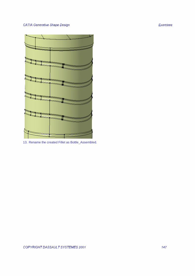
13. Rename the created Fillet as Bottle_Assembled.

&$7,$�*HQHUDWLYH�6KDSH�'HVLJQ� � ([HUFLVHV��
&23<5,*+7�'$66$8/7�6<67(0(6������ � ����� �
���(�������������������,���-1. Insert a new Open Body
&$7,$�*HQHUDWLYH�6KDSH�'HVLJQ� � ([HUFLVHV��
&23<5,*+7�'$66$8/7�6<67(0(6������ � ����� �
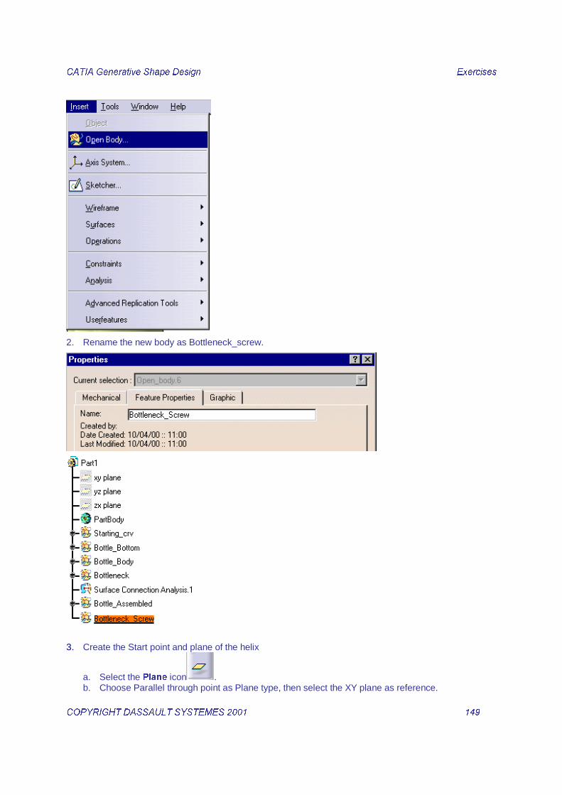
2. Rename the new body as Bottleneck_screw.
3. Create the Start point and plane of the helix
a. Select the 3ODQH icon . b. Choose Parallel through point as Plane type, then select the XY plane as reference.

&$7,$�*HQHUDWLYH�6KDSH�'HVLJQ� � ([HUFLVHV��
&23<5,*+7�'$66$8/7�6<67(0(6������ � ����� �
c. Open a contextual menu in the point field to create on the fly the Point. Select Create Point.
d. Choose 2Q�FXUYH as Point type. Select the 6NHWFK�� as Curve then enter a ���PP distance from
the upper vertex of the sketch as shown below.

&$7,$�*HQHUDWLYH�6KDSH�'HVLJQ� � ([HUFLVHV��
&23<5,*+7�'$66$8/7�6<67(0(6������ � ����� �
e. Click on OK to create the point, the definition is now complete.

&$7,$�*HQHUDWLYH�6KDSH�'HVLJQ� � ([HUFLVHV��
&23<5,*+7�'$66$8/7�6<67(0(6������ � ����� �
f. Click on OK to create the new plane.
4. Create the helix a. Select the +HOL[ icon.
b. Select the last created Point.5 as Starting point. Select the Intersect.1 as axis. Enter a pitch =
3mm and a Height = 7 mm then choose Counterclockwise as orientation.

&$7,$�*HQHUDWLYH�6KDSH�'HVLJQ� � ([HUFLVHV��
&23<5,*+7�'$66$8/7�6<67(0(6������ � ����� �
c. Click on OK to create the helix.
5. Create the line.
a. Select the /LQH icon . b. Choose an Angle/Normal to curve as Line type. Complete the definition fields as shown below.
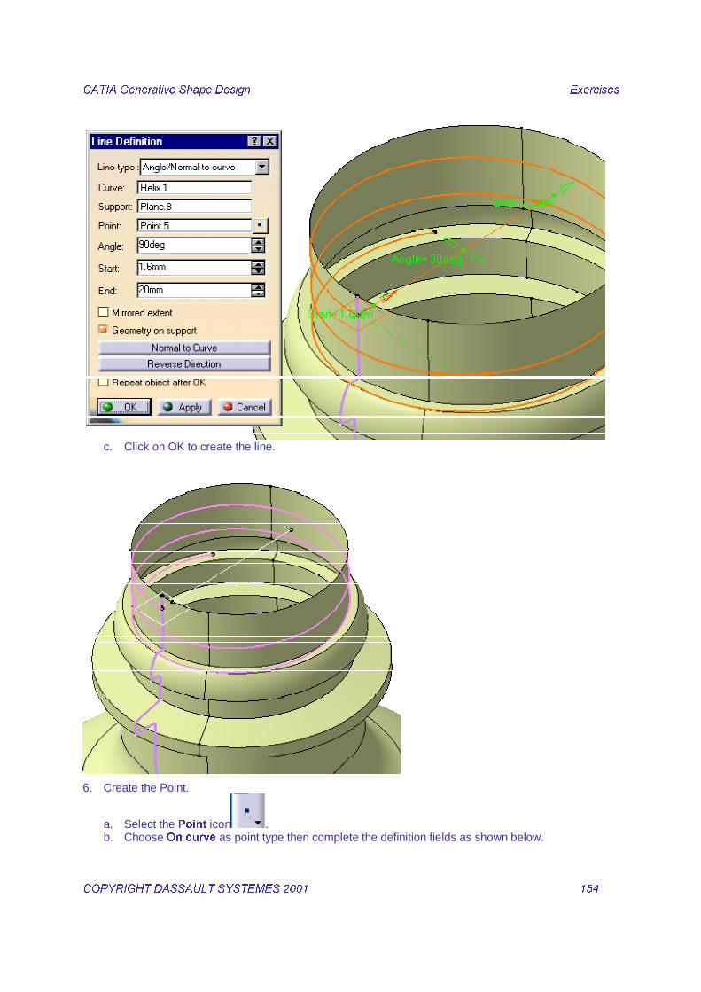
&$7,$�*HQHUDWLYH�6KDSH�'HVLJQ� � ([HUFLVHV��
&23<5,*+7�'$66$8/7�6<67(0(6������ � ����� �
c. Click on OK to create the line.
6. Create the Point.
a. Select the 3RLQW icon . b. Choose 2Q�FXUYH as point type then complete the definition fields as shown below.

&$7,$�*HQHUDWLYH�6KDSH�'HVLJQ� � ([HUFLVHV��
&23<5,*+7�'$66$8/7�6<67(0(6������ � ����� �
c. Click on OK to create the point.
7. Connect the curves.
a. Select the &RQQHFW�&XUYH icon . b. Select the /LQH���DQG�YHUWH[���as first curve elements then the +HOL[�� and 3RLQW�� as second
curve elements.

&$7,$�*HQHUDWLYH�6KDSH�'HVLJQ� � ([HUFLVHV��
&23<5,*+7�'$66$8/7�6<67(0(6������ � ����� �
c. Click on OK to confirm the curve creation.

&$7,$�*HQHUDWLYH�6KDSH�'HVLJQ� � ([HUFLVHV��
&23<5,*+7�'$66$8/7�6<67(0(6������ � ����� �
8. Create a Implicit circular profile swept surface.
a. Select the 6ZHHS icon . b. Choose the Implicit circular profile and the Center and radius subtype.
c. Select the &RQQHFW�� as Center curve then enter a UDGLXV of ����PP.

&$7,$�*HQHUDWLYH�6KDSH�'HVLJQ� � ([HUFLVHV��
&23<5,*+7�'$66$8/7�6<67(0(6������ � ����� �
d. Click on OK to create the swept surface.
9. Assemble the sweep with the assembled bottle.
a. Select the 7ULP icon .

&$7,$�*HQHUDWLYH�6KDSH�'HVLJQ� � ([HUFLVHV��
&23<5,*+7�'$66$8/7�6<67(0(6������ � ����� �
b. Select the %RWWOHB$VVHPEOHG�fillet then the just created�6ZHHS���as elements.
c. Click on OK to confirm the trim creation.
&$7,$�*HQHUDWLYH�6KDSH�'HVLJQ� � ([HUFLVHV��
&23<5,*+7�'$66$8/7�6<67(0(6������ � ����� �

&$7,$�*HQHUDWLYH�6KDSH�'HVLJQ� � ([HUFLVHV��
&23<5,*+7�'$66$8/7�6<67(0(6������ � ����� �
����'���������������.
��������������/������&��&.
1. Select the 6NHWFKHU icon .
2. Draw the following Sketch.

&$7,$�*HQHUDWLYH�6KDSH�'HVLJQ� � ([HUFLVHV��
&23<5,*+7�'$66$8/7�6<67(0(6������ � ����� �
3. Exit the Sketcher
4. Switch to the Generative Shape Design workbench.
5. Select the 3ODQH icon. a. Choose 2IIVHW IURP 3ODQH as Plane type. b. In the 5HIHUHQFH field, open a contextual menu and select &UHDWH�3ODQH.
c. In the new Plane Definition dialog box, choose $QJOH�1RUPDO�WR�3ODQH as plane type d. In the 5RWDWLRQ D[LV field open a contextual menu then select &UHDWH /LQH.
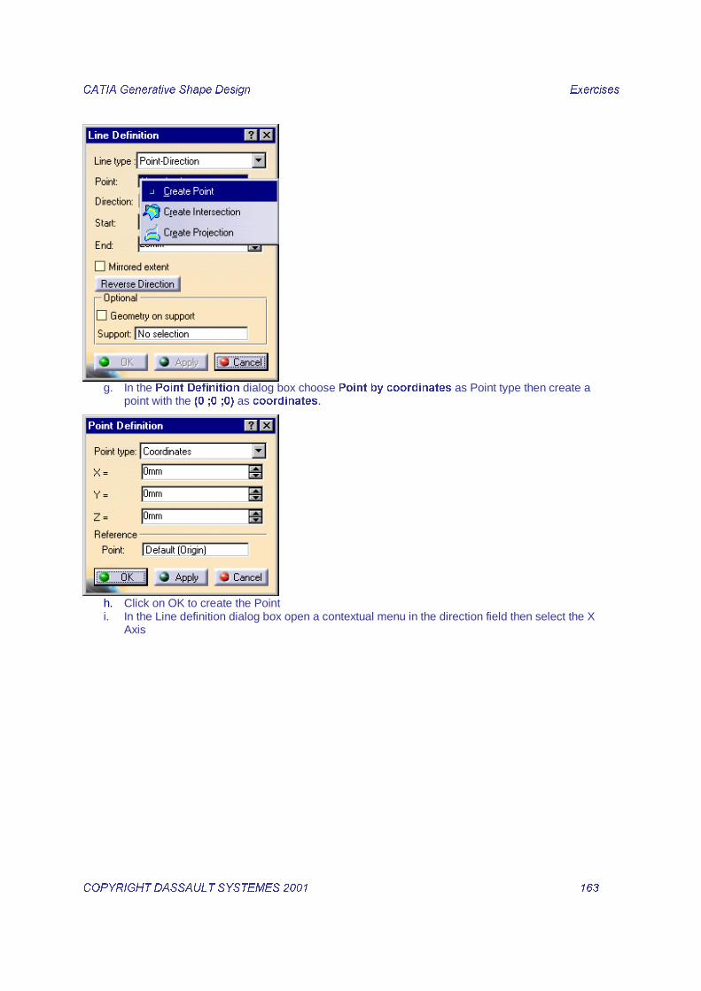
�e. In the /LQH�'HILQLWLRQ dialog box, choose 3RLQW�'LUHFWLRQ as Line type f. In the 3RLQW field open a contextual menu then select &UHDWH�3RLQW.
&$7,$�*HQHUDWLYH�6KDSH�'HVLJQ� � ([HUFLVHV��
&23<5,*+7�'$66$8/7�6<67(0(6������ � ����� �
g. In the 3RLQW 'HILQLWLRQ dialog box choose 3RLQW�E\�FRRUGLQDWHV as Point type then create a
point with the ��������� as FRRUGLQDWHV.
h. Click on OK to create the Point i. In the Line definition dialog box open a contextual menu in the direction field then select the X
Axis

&$7,$�*HQHUDWLYH�6KDSH�'HVLJQ� � ([HUFLVHV��
&23<5,*+7�'$66$8/7�6<67(0(6������ � ����� �
�j. Click on OK to create the Line. k. In the Plane Definition dialog box select XY plane as reference and enter a Angle of 6.5 deg.
l. Click on OK to create the Plane.
6. In the Plane Definition dialog enter an offset value of 15 mm
�
&$7,$�*HQHUDWLYH�6KDSH�'HVLJQ� � ([HUFLVHV��
&23<5,*+7�'$66$8/7�6<67(0(6������ � ����� �
�
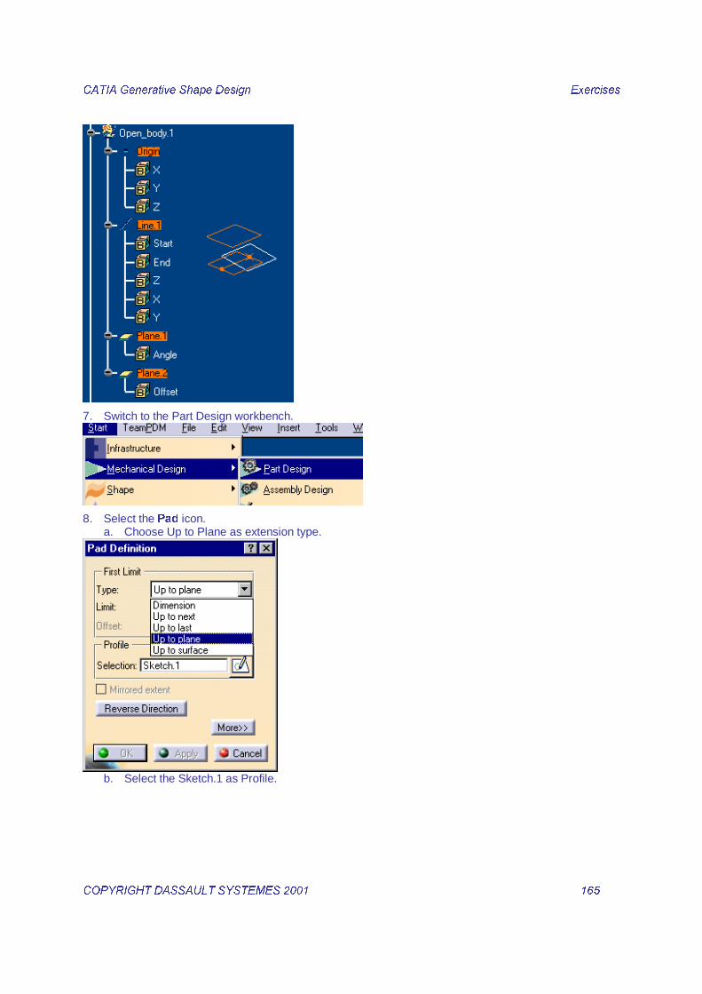
7. Switch to the Part Design workbench.
�
8. Select the 3DG icon. a. Choose Up to Plane as extension type.
�b. Select the Sketch.1 as Profile.

&$7,$�*HQHUDWLYH�6KDSH�'HVLJQ� � ([HUFLVHV��
&23<5,*+7�'$66$8/7�6<67(0(6������ � ����� �
�c. Select the last created Plane as Limit.
�d. Click on OK to create the Pad.

&$7,$�*HQHUDWLYH�6KDSH�'HVLJQ� � ([HUFLVHV��
&23<5,*+7�'$66$8/7�6<67(0(6������ � ����� �
�
9. Select the Fillet icon. a. Select the upper edge as shown below.
�b. Click on OK to create the Fillet.
�
������������������������������.1. Switch to the Generative Shape Design workbench.

&$7,$�*HQHUDWLYH�6KDSH�'HVLJQ� � ([HUFLVHV��
&23<5,*+7�'$66$8/7�6<67(0(6������ � ����� �
2. Select the 3ODQH icon by a double click. a. Choose 2IIVHW IURP 3ODQH as Plane type. b. Select the ZX plane as reference and enter 10mm as Offset value.
c. Click on OK to create the plane. d. Select the ZX plane as reference and enter 110mm as Offset value.
e. Click on OK to create the plane.
3. Select the 6NHWFKHU icon .
4. Draw the following Sketch on the created Plane.3

&$7,$�*HQHUDWLYH�6KDSH�'HVLJQ� � ([HUFLVHV��
&23<5,*+7�'$66$8/7�6<67(0(6������ � ����� �
5. Exit the Sketcher
6. Select the 6NHWFKHU icon.
7. Draw the following Sketch on the created Plane.4
8. Exit the Sketcher

&$7,$�*HQHUDWLYH�6KDSH�'HVLJQ� � ([HUFLVHV��
&23<5,*+7�'$66$8/7�6<67(0(6������ � ����� �
9. Select the Loft icon.
10. Create a simple Loft using the two created sketches as Sections
11. Select the Line icon. a. Choose Point-Point as Line type then select the indicated vertices as shown below.

&$7,$�*HQHUDWLYH�6KDSH�'HVLJQ� � ([HUFLVHV��
&23<5,*+7�'$66$8/7�6<67(0(6������ � ����� �
�b. Click on OK to create the Line.
12. Select the Fill surface icon . a. In the Fill Surface Definition panel select the green and blue curves as boundary curves as shown
below.

&$7,$�*HQHUDWLYH�6KDSH�'HVLJQ� � ([HUFLVHV��
&23<5,*+7�'$66$8/7�6<67(0(6������ � ����� �
b. Click on OK to create the Surface.
13. Select the Join icon a. Select the just created Fill.1 and Loft.2 as Elements to join.

&$7,$�*HQHUDWLYH�6KDSH�'HVLJQ� � ([HUFLVHV��
&23<5,*+7�'$66$8/7�6<67(0(6������ � ����� �
b. Click on OK to create the surface.
14. Select the Split icon a. Select the Join as Element to cut then the bottom face of the Pad as cutting element.
��
b. Click on OK to create the surface.

&$7,$�*HQHUDWLYH�6KDSH�'HVLJQ� � ([HUFLVHV��
&23<5,*+7�'$66$8/7�6<67(0(6������ � ����� �
�
��� ��-���������������!�&.1. Switch to the Part Design workbench.
�
2. Select the 6HZ VXUIDFH icon.
�a. Select the previous Trim surface as shown below.
�b. Click on the red arrows to orient the material direction.
�c. Click on OK to create the solid.

&$7,$�*HQHUDWLYH�6KDSH�'HVLJQ� � ([HUFLVHV��
&23<5,*+7�'$66$8/7�6<67(0(6������ � ����� �
�
3. Hide the surface.
�
���#����������������.
1. Select the 6NHWFKHU icon .
2. Draw the following Sketch on the YZ Plane

&$7,$�*HQHUDWLYH�6KDSH�'HVLJQ� � ([HUFLVHV��
&23<5,*+7�'$66$8/7�6<67(0(6������ � ����� �
3. Exit the Sketcher
4. Select the�*URRYH�icon. a. Select the�just created sketch as Profile then enter the parameters as shown below..
�b. Click on OK to create the Groove.

&$7,$�*HQHUDWLYH�6KDSH�'HVLJQ� � ([HUFLVHV��
&23<5,*+7�'$66$8/7�6<67(0(6������ � ����� �
�
���(������������&-������������&�������.1. Select the ,PSRUWHG�6XUIDFH in the tree and show it.
�
&$7,$�*HQHUDWLYH�6KDSH�'HVLJQ� � ([HUFLVHV��
&23<5,*+7�'$66$8/7�6<67(0(6������ � ����� �
�
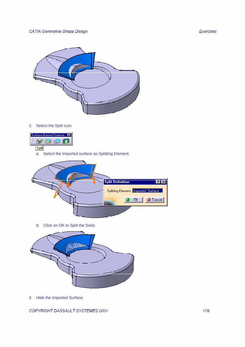
2. Select the Split icon.
�a. Select the Imported surface as Splitting Element.
�b. Click on OK to Split the Solid.
�
3. Hide the Imported Surface.

&$7,$�*HQHUDWLYH�6KDSH�'HVLJQ� � ([HUFLVHV��
&23<5,*+7�'$66$8/7�6<67(0(6������ � ����� �
�
���0��������������&����&.1. Select the Shell icon.
a. Select the bottom face as Face to remove and enter an inside thickness of 2mm.
�b. Click on OK to create the Shell.
�
&$7,$�*HQHUDWLYH�6KDSH�'HVLJQ� � ([HUFLVHV��
&23<5,*+7�'$66$8/7�6<67(0(6������ � ����� �
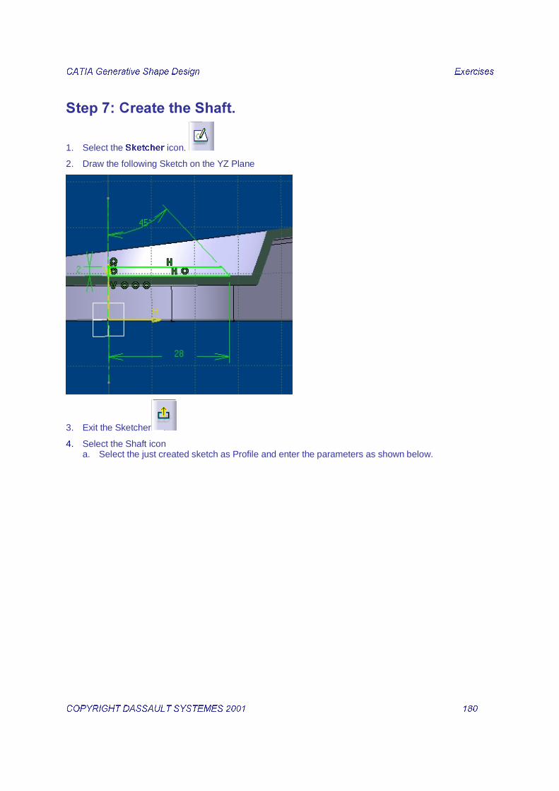
���1��������������.
1. Select the 6NHWFKHU icon.
2. Draw the following Sketch on the YZ Plane
3. Exit the Sketcher
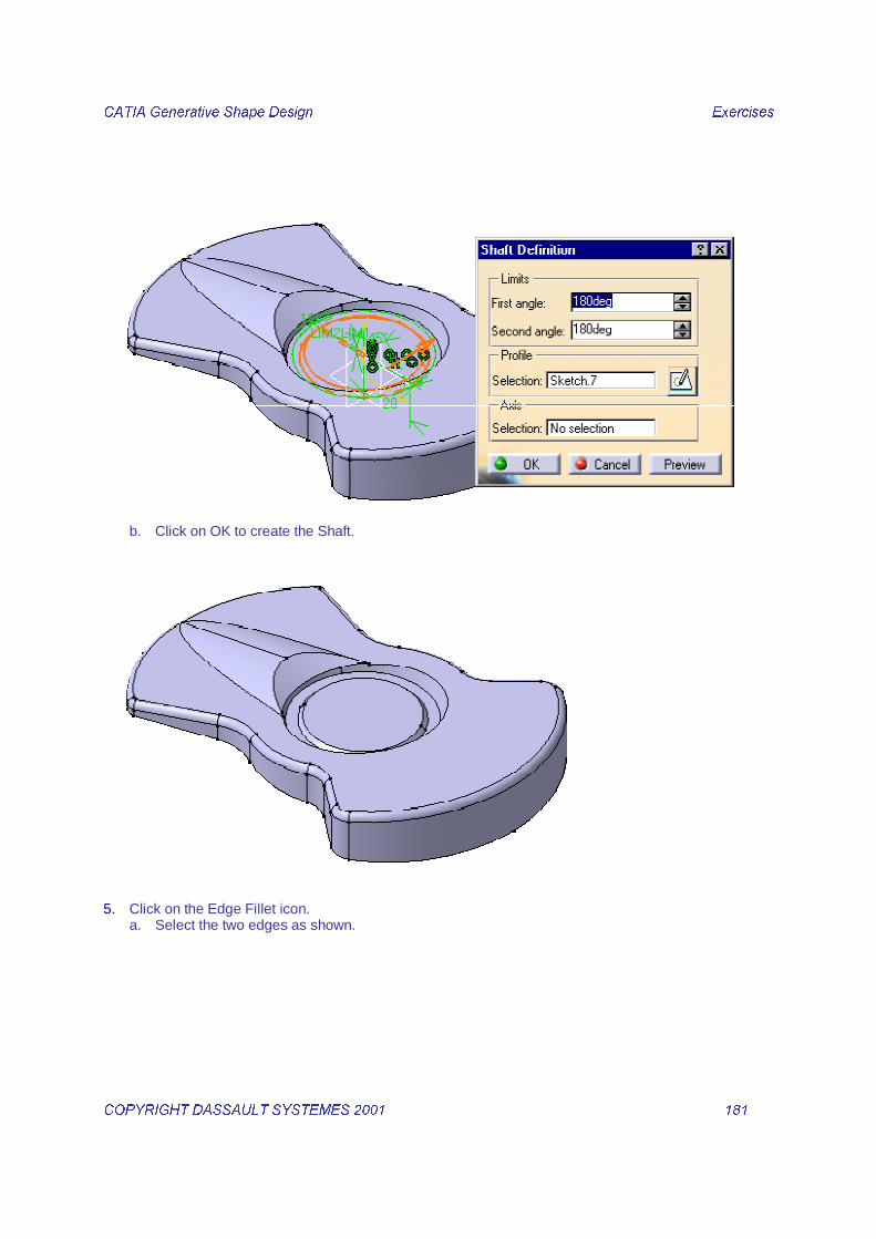
4. Select the Shaft icon a. Select the just created sketch as Profile and enter the parameters as shown below.
&$7,$�*HQHUDWLYH�6KDSH�'HVLJQ� � ([HUFLVHV��
&23<5,*+7�'$66$8/7�6<67(0(6������ � ����� �
b. Click on OK to create the Shaft.
�
5. Click on the Edge Fillet icon. a. Select the two edges as shown.

&$7,$�*HQHUDWLYH�6KDSH�'HVLJQ� � ([HUFLVHV��
&23<5,*+7�'$66$8/7�6<67(0(6������ � ����� �
b. Click on OK to confirm.
�
���2����������3������&!��,���.1. Select the +ROH icon.

&$7,$�*HQHUDWLYH�6KDSH�'HVLJQ� � ([HUFLVHV��
&23<5,*+7�'$66$8/7�6<67(0(6������ � ����� �
a. Select the upper face of the just created shaft.
�b. Choose 6LPSOH as Hole type, then 8S�WR�1H[W as Extension type and enter ��PP as Diameter
value.
�c. Click on OK to create the Hole.

&$7,$�*HQHUDWLYH�6KDSH�'HVLJQ� � ([HUFLVHV��
&23<5,*+7�'$66$8/7�6<67(0(6������ � ����� �
�
2. Select the 6NHWFKHU icon.
3. Draw the following Sketch on the Upper plane of the part.
�
4. Perform a symmetry on this sketch using the vertical axis as reference.

&$7,$�*HQHUDWLYH�6KDSH�'HVLJQ� � ([HUFLVHV��
&23<5,*+7�'$66$8/7�6<67(0(6������ � ����� �
�
5. Exit the Sketcher
6. Select the�3RFNHW�icon. a. Select the�MXVW�&UHDWHG�VNHWFK. Choose Up to Next as type.
�b. Click on OK to create the pocket.

&$7,$�*HQHUDWLYH�6KDSH�'HVLJQ� � ([HUFLVHV��
&23<5,*+7�'$66$8/7�6<67(0(6������ � ����� �
�
7. Select the +ROH icon. a. Select the upper face of part.
�b. Choose 6LPSOH as Hole type, then 8S�WR�1H[W as Extension type and enter ��PP as Diameter
value.

&$7,$�*HQHUDWLYH�6KDSH�'HVLJQ� � ([HUFLVHV��
&23<5,*+7�'$66$8/7�6<67(0(6������ � ����� �
�c. Under the Hole node in the tree double ckick on the created sketch of the hole to open it
�d. Add the following contraints on the hole center.

&$7,$�*HQHUDWLYH�6KDSH�'HVLJQ� � ([HUFLVHV��
&23<5,*+7�'$66$8/7�6<67(0(6������ � ����� �
�
e. Exit the Sketcher
8. Select the 6NHWFKHU icon.
9. Draw the following Sketch on the Upper plane of the part.

&$7,$�*HQHUDWLYH�6KDSH�'HVLJQ� � ([HUFLVHV��
&23<5,*+7�'$66$8/7�6<67(0(6������ � ����� �
�
10. Exit the Sketcher
11. Select the 8VHU�3DWWHUQ icon.
�a. Select the previous hole as element to repeat.

&$7,$�*HQHUDWLYH�6KDSH�'HVLJQ� � ([HUFLVHV��
&23<5,*+7�'$66$8/7�6<67(0(6������ � ����� �
�b. Select the just created sketch as positions template.
�c. Click on OK to confirm the pattern creation.

&$7,$�*HQHUDWLYH�6KDSH�'HVLJQ� � ([HUFLVHV��
&23<5,*+7�'$66$8/7�6<67(0(6������ � ����� �
�
12. Select the (GJH�)LOOHW icon. a. Select the upper edges of the just created holes and enter a radius of 0.5 mm.
�b. Click on OK to confirm the edge fillet creation
13. Select the 6NHWFKHU icon.
14. Draw the following Sketch on the ZX plane.

&$7,$�*HQHUDWLYH�6KDSH�'HVLJQ� � ([HUFLVHV��
&23<5,*+7�'$66$8/7�6<67(0(6������ � ����� �
�
15. Exit the Sketcher
16. Select the�3RFNHW�icon. a. Select the�MXVW�&UHDWHG�VNHWFK. Choose Up to Next as type.
�b. Click on OK to create the pocket.

&$7,$�*HQHUDWLYH�6KDSH�'HVLJQ� � ([HUFLVHV��
&23<5,*+7�'$66$8/7�6<67(0(6������ � ����� �
�
���4�$����������-��&�.1. Insert a new Body.
�
2. Select the 6NHWFKHU icon.
3. Draw the following sketch on the YZ plane.
�
4. Select the Shaft icon. a. Select the just created sketch as profile. Enter 12.5 degrees as First and second angles.

&$7,$�*HQHUDWLYH�6KDSH�'HVLJQ� � ([HUFLVHV��
&23<5,*+7�'$66$8/7�6<67(0(6������ � ����� �
�b. Click on OK to create the shaft.
5. Select the (GJH )LOOHW icon. a. Select the following edges on thge created shaft then enter a radius value of 0.4mm.
�b. Click on OK to create the fillet.
�
6. Select the 6NHWFKHU icon.
7. Select the bottom face of the part as sketch support.

&$7,$�*HQHUDWLYH�6KDSH�'HVLJQ� � ([HUFLVHV��
&23<5,*+7�'$66$8/7�6<67(0(6������ � ����� �
�
8. Draw the following circle.
�
9. Exit the Sketcher
10. Select the Pad icon. a. Select the previous sketch as profile and enter a length of 3mm.

&$7,$�*HQHUDWLYH�6KDSH�'HVLJQ� � ([HUFLVHV��
&23<5,*+7�'$66$8/7�6<67(0(6������ � ����� �
b. Click on OK to confirm the Pad creation.
�
11. Assemble the Body with the Upper Part Body.

&$7,$�*HQHUDWLYH�6KDSH�'HVLJQ� � ([HUFLVHV��
&23<5,*+7�'$66$8/7�6<67(0(6������ � ����� �
�
12. Click on OK in the Assemble dialog box.
�

&$7,$�*HQHUDWLYH�6KDSH�'HVLJQ� � ([HUFLVHV��
&23<5,*+7�'$66$8/7�6<67(0(6������ � ����� �
�
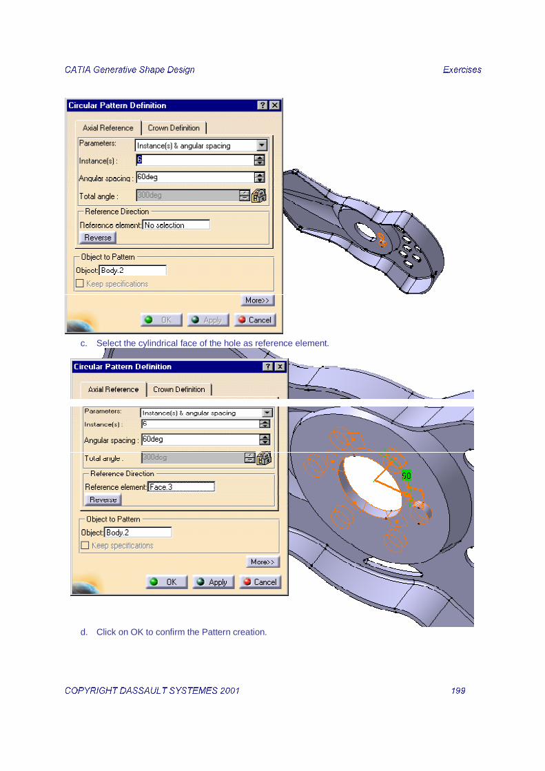
13. Create a circular pattern with the new body. a. Select the FLUFXODU SDWWHUQ icon
�b. Select the just created Body.2 as element to repeat. Enter 6 as number of instances then 60
degrees as angular spacing.
&$7,$�*HQHUDWLYH�6KDSH�'HVLJQ� � ([HUFLVHV��
&23<5,*+7�'$66$8/7�6<67(0(6������ � ����� �
�c. Select the cylindrical face of the hole as reference element.
�d. Click on OK to confirm the Pattern creation.

&$7,$�*HQHUDWLYH�6KDSH�'HVLJQ� � ([HUFLVHV��
&23<5,*+7�'$66$8/7�6<67(0(6������ � ����� �
�
14. You can add a material to end the part definition.
�

&$7,$�*HQHUDWLYH�6KDSH�'HVLJQ� � ([HUFLVHV��
&23<5,*+7�'$66$8/7�6<67(0(6������ � ����� �
�����������5����6���%��We will design this lemon squeezer using:
- Swept, fill and blended surfaces.
- Operations on these surfaces.
������������������-����������������
1. Using the icon at the bottom of the screen, create an evolution law: a. In the LAW EDITOR window, declare 2 parameters (real type) clicking 2 times on this button:
b. 2 new parameters appear in the parameter list:

&$7,$�*HQHUDWLYH�6KDSH�'HVLJQ� � ([HUFLVHV��
&23<5,*+7�'$66$8/7�6<67(0(6������ � ����� �
F�� And now type in the following formula: < DEV���VLQ����p�;����
Note: to make parameters appear in the formula, double-click on the parameter in the parameter list.
2. We are going to use this law to create a curve parallel to Circle.1.
a. Click on this icon: b. Curve: select Circle.1 c. Support: select Plane.3 in the tree. d. Mode: select the LAW mode and select in the tree the previously created law: Law.1

&$7,$�*HQHUDWLYH�6KDSH�'HVLJQ� � ([HUFLVHV��
&23<5,*+7�'$66$8/7�6<67(0(6������ � ����� �
1. We are going to create the symmetry to Parallel.1 using Project.2 as reference.
a. Click the icon b. Element: Parallel.1 c. Reference: Project.2
d. Finally join two symmetric elements
2. We are going to create an extremum point (minimum) on the Sketch.1 using the Z direction.
a. Click on the icon b. Element: Sketch.1 c. Direction: W Axis d. Mode: min
&$7,$�*HQHUDWLYH�6KDSH�'HVLJQ� � ([HUFLVHV��
&23<5,*+7�'$66$8/7�6<67(0(6������ � ����� �
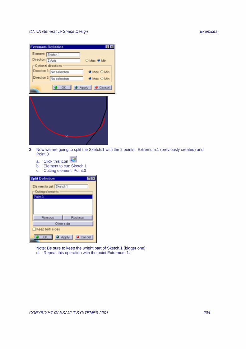
3. Now we are going to split the Sketch.1 with the 2 points : Extremum.1 (previously created) and Point.3
a. Click this icon b. Element to cut: Sketch.1 c. Cutting element: Point.3
Note: Be sure to keep the wright part of Sketch.1 (bigger one). d. Repeat this operation with the point Extremum.1:

&$7,$�*HQHUDWLYH�6KDSH�'HVLJQ� � ([HUFLVHV��
&23<5,*+7�'$66$8/7�6<67(0(6������ � ����� �
4. Now we will translate the point Project.2 in the Z direction (offset: 10mm)
a. Click the icon b. Element: Project.2 c. Direction: select Plane.3 in the tree (CATIA will take as direction the normal to this plane: Z)
�

&$7,$�*HQHUDWLYH�6KDSH�'HVLJQ� � ([HUFLVHV��
&23<5,*+7�'$66$8/7�6<67(0(6������ � ����� �
5. We are going to create a plane parallel to the Plane.3 and passing through the previously created point
a. Click this icon b. Plane type: Parallel through point c. Reference: Plane.3 d. Point: Translate.2
�
6. Now we will create a circle lying on this new plane, centered on the point Translate.2 (radius=2mm)
a. Click the icon b. Circle type: center and radius c. Center: Translate.2 d. Support: Plane.5 e. Radius: 2mm
f. Circle limitations mode :

&$7,$�*HQHUDWLYH�6KDSH�'HVLJQ� � ([HUFLVHV��
&23<5,*+7�'$66$8/7�6<67(0(6������ � ����� �
�
7. Finally we will translate the point Translate.2 normally to Plane.5 (offset=1.2mm)
a. Click the icon b. Element: Translate.2 c. Direction: Plane.5 d. Distance: 1.2mm
�����������������������������1. We are going to use the previously created wireframe elements to create an explicit sweep
a. Click this icon
b. Profile type: explicit c. Profile: Split.3 d. Guiding curve: Join.2 e. Spine: Circle.4

&$7,$�*HQHUDWLYH�6KDSH�'HVLJQ� � ([HUFLVHV��
&23<5,*+7�'$66$8/7�6<67(0(6������ � ����� �
2. Create the lower boundary of this surface: a. We are going to use the previously created wireframe elements to create a circle sweep
b. Click this icon
c. Profile type: circle d. Subtype: Two guides and tangency surface e. Limit curve with tangency: Boundary.3 f. Tangency surface: Sweep.1 g. Limit curve: Circle.4 h. Spine: Circle.4

&$7,$�*HQHUDWLYH�6KDSH�'HVLJQ� � ([HUFLVHV��
&23<5,*+7�'$66$8/7�6<67(0(6������ � ����� �
�
3. Join the two previously created surfaces using the icon
4. Now we are going to fill the Circle.5 passing through the point Translate.3
a. Click the icon b. Boundary curve: Circle.5 c. Passing point: Translate.3

&$7,$�*HQHUDWLYH�6KDSH�'HVLJQ� � ([HUFLVHV��
&23<5,*+7�'$66$8/7�6<67(0(6������ � ����� �
�
The basic surfaces are created.
��� ��������������&�������-�������������&�&&���������&��1. First, we are going to create the wireframe that will support the coupling points creation
a. Click the icon b. Select the upper edge of the surface Sweep.1
c. Click OK. The upper boundary is created.

&$7,$�*HQHUDWLYH�6KDSH�'HVLJQ� � ([HUFLVHV��
&23<5,*+7�'$66$8/7�6<67(0(6������ � ����� �
1RWH: Do not forget to select the propagation mode called Point Continuity
d. Click the icon to create a plane passing through the previously created boundary e. Select the Boundary.4
f. Then create a point on this plane (coordinate: 0,0) clicking the icon and selecting the mode On Plane.
g. Key in the coordinates: H=0 and V=0.
2. Now, we are going to create the first coupling point using the function Polar Extremum
a. Click the icon
Type: Min Radius b. Contour: Boundary.4 c. Support: Plane.6 (previously created) d. Origin: Point.5 (previously created) e. Reference direction: X (select it with the 3rd button of the mouse)
f. CATIA calculates the point on the curve that is the closer from the origin point (Point.5)

&$7,$�*HQHUDWLYH�6KDSH�'HVLJQ� � ([HUFLVHV��
&23<5,*+7�'$66$8/7�6<67(0(6������ � ����� �
g. As you see, many points are possible. We will keep only one:
h. Select YES and then choose the Point.3 as reference element:
�
3. Now we are going to create the next coupling point.
a. Click this icon b. Select the mode On Curve c. Select the curve Boundary.4 d. Select the option Ratio of Curve Length e. Choose the point Near.1 as reference point (previously created) f. Key in the ratio 0.1

&$7,$�*HQHUDWLYH�6KDSH�'HVLJQ� � ([HUFLVHV��
&23<5,*+7�'$66$8/7�6<67(0(6������ � ����� �
�
g. Repeat the operation 8 times, each time choosing the previously created point as reference point:
&$7,$�*HQHUDWLYH�6KDSH�'HVLJQ� � ([HUFLVHV��
&23<5,*+7�'$66$8/7�6<67(0(6������ � ����� �
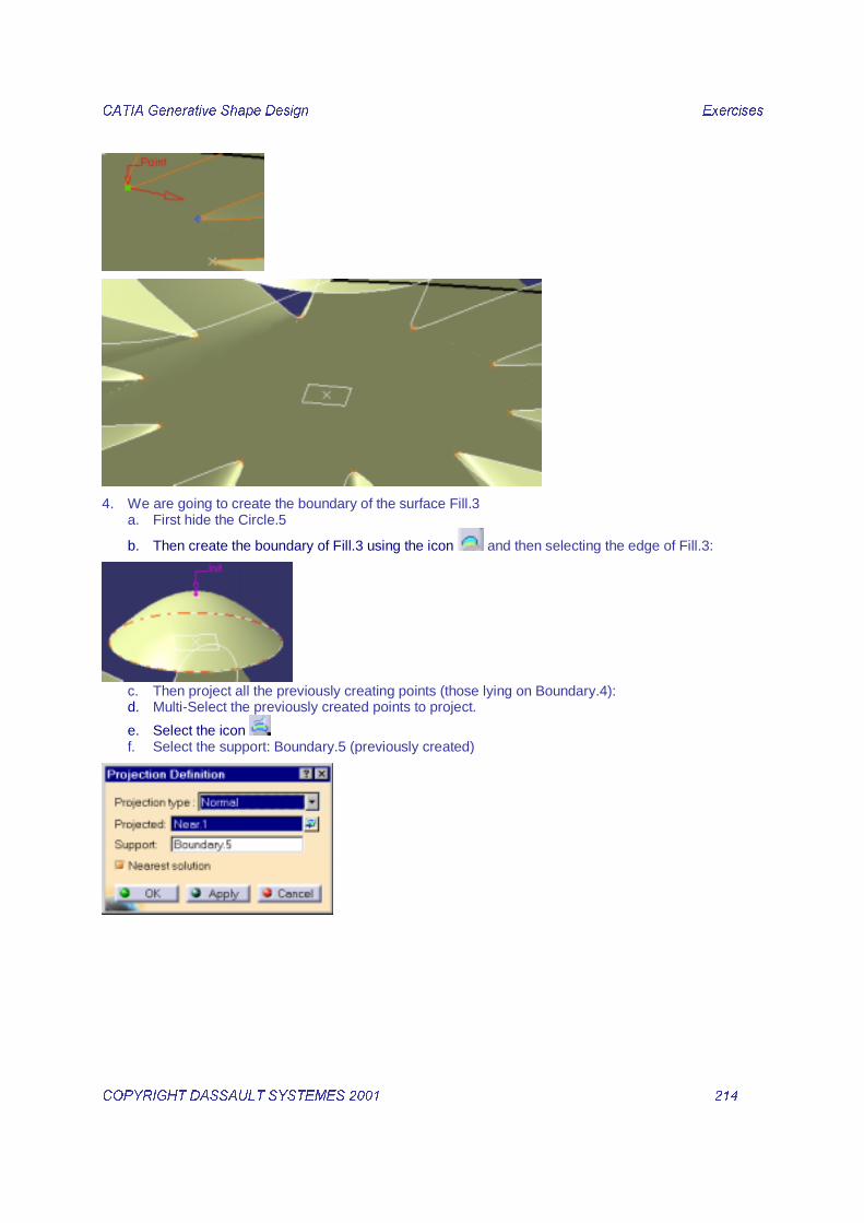
4. We are going to create the boundary of the surface Fill.3 a. First hide the Circle.5
b. Then create the boundary of Fill.3 using the icon and then selecting the edge of Fill.3:
c. Then project all the previously creating points (those lying on Boundary.4): d. Multi-Select the previously created points to project.
e. Select the icon f. Select the support: Boundary.5 (previously created)
�

&$7,$�*HQHUDWLYH�6KDSH�'HVLJQ� � ([HUFLVHV��
&23<5,*+7�'$66$8/7�6<67(0(6������ � ����� �
5. The coupling points are now ready. We are going to use them to create the connecting surface between Fill.3 and Join.3 (the 2 swept surfaces previously garthered)
a. Click the icon b. Select Boundary.4 as first curve and Join.3 as first support. Selecting Join.3 as first support, we
are adding a tangency condition between the blend surface and Join.3. c. Select Boundary.5 as second curve but GR�QRW�VHOHFW�)LOO���DV�VHFRQG�VXSSRUW. d. Select the option coupling:
e. And now select the coupling points (Near.1 and its projected point…) so that you should get this:

&$7,$�*HQHUDWLYH�6KDSH�'HVLJQ� � ([HUFLVHV��
&23<5,*+7�'$66$8/7�6<67(0(6������ � ����� �
f. Click OK to terminate the blend creation.

&$7,$�*HQHUDWLYH�6KDSH�'HVLJQ� � ([HUFLVHV��
&23<5,*+7�'$66$8/7�6<67(0(6������ � ����� �
Note: Always make sure the two selected curves are oriented in the same direction. If not, click on the red arrow to invert the direction as shown:
The blend surface is created. You can now join it to Join.3 and Fill.3 with the icon .
The resulting entity is called Join.4
6. We are now going to add the handle to the previously created surfaces. a. Show the handle.

&$7,$�*HQHUDWLYH�6KDSH�'HVLJQ� � ([HUFLVHV��
&23<5,*+7�'$66$8/7�6<67(0(6������ � ����� �
b. Trim it with Join.4 by clicking the icon and selecting the handle and Join.4
Note: the operation is made in Open.Body.4 but the handle is another Open.Body. So, the original handle is not automatically hidden. You have to hide it yourself to visualize the result of the trim operation.
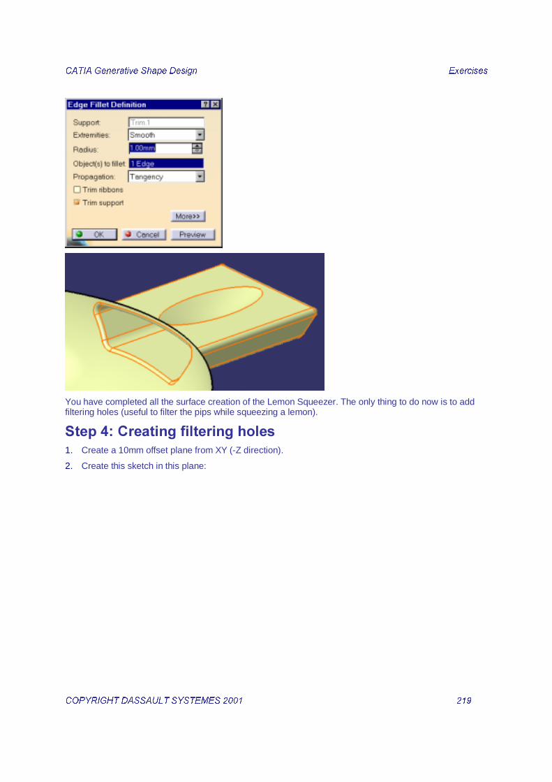
7. Finally, we are going to add a fillet on the sharp edge shown above.
a. Click the icon b. Select the sharp edge and key in a 1mm radius value.
&$7,$�*HQHUDWLYH�6KDSH�'HVLJQ� � ([HUFLVHV��
&23<5,*+7�'$66$8/7�6<67(0(6������ � ����� �
�
You have completed all the surface creation of the Lemon Squeezer. The only thing to do now is to add filtering holes (useful to filter the pips while squeezing a lemon).
���#�����������������������1. Create a 10mm offset plane from XY (-Z direction).
2. Create this sketch in this plane:

&$7,$�*HQHUDWLYH�6KDSH�'HVLJQ� � ([HUFLVHV��
&23<5,*+7�'$66$8/7�6<67(0(6������ � ����� �
3. We are going to create a circular pattern in order to repeat this geometry.
a. Select the previously created sketch and click the icon b. Parameters: angular spacing and total angle. c. Angular spacing: 18deg d. Total angle: 342deg e. Reference element: Plane.7 (previously created)

&$7,$�*HQHUDWLYH�6KDSH�'HVLJQ� � ([HUFLVHV��
&23<5,*+7�'$66$8/7�6<67(0(6������ � ����� �
4. Now we are going to project Sketch.6 (ellipse) and CircPattern.1 on the main surface called EdgeFillet.2.
a. Click the icon and select the Sketch.6. b. Projection type: Along a direction c. Support: EdgeFillet.2 d. Direction: Z (select it by clicking with the 3rd button of the mouse in the direction panel)
&$7,$�*HQHUDWLYH�6KDSH�'HVLJQ� � ([HUFLVHV��
&23<5,*+7�'$66$8/7�6<67(0(6������ � ����� �
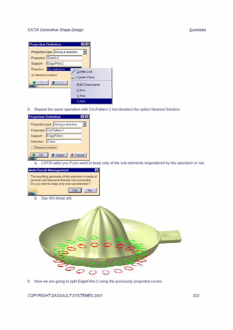
5. Repeat the same operation with CircPattern.1 but deselect the option Nearest Solution:
a. CATIA asks you if you want to keep only of the sub-elements engendered by the operation or not:
b. Say NO (keep all).
6. Now we are going to split EdgeFillet.2 using the previously projected curves

&$7,$�*HQHUDWLYH�6KDSH�'HVLJQ� � ([HUFLVHV��
&23<5,*+7�'$66$8/7�6<67(0(6������ � ����� �
a. Select the icon and select EdgeFillet.2 (main surface) as element to cut. b. Select the first projected curve (ellipse projection) as cutting element.
7. You obtain a result called Split.4. Now split Split.4 the same way but using the Circular pattern projection as cutting element.
Note: even if this projection contains many disconnected curves, CATIA sees it as only one entity.

&$7,$�*HQHUDWLYH�6KDSH�'HVLJQ� � ([HUFLVHV��
&23<5,*+7�'$66$8/7�6<67(0(6������ � ����� �