generative design of a mechanical pedal
TRANSCRIPT

International Journal of Engineering and Management Sciences (IJEMS) Vol. 6. (2021). No. 1
DOI: 10.21791/IJEMS.2021.1.5.
48
Generative Design of a Mechanical Pedal
M. FENOON1, O. ALQUABEH2, M.M. NISAR3, S. ZIA4.
1University of Debrecen, Faculty of Engineering, Department of Mechanical Engineering, [email protected] 2University of Debrecen, Faculty of Engineering, Department of Mechanical Engineering, [email protected] 3University of Debrecen, Faculty of Engineering, Department of Mechanical Engineering. [email protected] 4University of Debrecen, Faculty of Engineering, Department of Mechanical Engineering, [email protected]
Abstract
Nowadays, there are various tools that support the initial stages of design available to use for engineers, the
traditional Computer-Aided Design (CAD) has been implemented in the engineering components design and replaced
manual drafting. However, with the advances and the rapid technology development, new trends emerged to cope
with this evolution, namely, Generative Design, Topology Optimization, and Generative Engineering Design. The
method is based on numerical algorithms that generate a variety of design and modelling options based on the criteria
and constraints set by the designer to allow further design exploration. Proposed in this paper is an implementation
of the generative design of a mechanical pedal with further finite element analysis.
Keywords: Computer-Aided Design (CAD), Generative Design (GD), Design Optimization, Generative CAD, Rapid
Modelling, 3D Modelling, Finite Element Analysis (FEA), Mesh Analysis, Mesh Sensitivity Analyses.
Introduction
The computer emerged to be a powerful tool utilized in engineering components design with the
capability to perform complex 3D modelling and analysis of various shapes and to overcome the manual
drawing and drafting. Acknowledging this potential, CAD is currently not only employed in final product
design, rather, in the early phases of design as well [1]. Generative CAD supports the users in conceptual
design and product development by allowing them to explore a wide range of feasible design options
based on the user-defined constraints, components function, aesthetic, performance, and cost [2]. The
designing phase has an important role in the cumulative cost, 60 to 80 % of the total cost is committed
in the initial stages of conception and design, therefore, efforts have been made to prevent the
accumulation of additional costs in design and later on phases [3]. With the use of special algorithms, it
allows engineers to optimize their designs around the specific requirement needed for that design, mass
reduction is a great example of that, wherein some cases engineers were able to reach up to 45% lighter
product as compared to the design made with the traditional design methods, which greatly benefit the
performance in many applications, in drones, cars, and aircraft, where all of these examples can benefit
from the lower weight which directly impacts their energy consumption, and fewer materials mean less
initial production cost [4]. Furthermore, the development of Additive Manufacturing (AM) technologies,
3D printing in particular, tremendously helped the utilisation of generative design, because
manufacturing is no longer limited to the traditional manufacturing process but rather engineers have

International Journal of Engineering and Management Sciences (IJEMS) Vol. 6. (2021). No. 1
DOI: 10.21791/IJEMS.2021.1.5.
49
the possibility to design parts that were not possible to manufacture in the past [4]. Several research
studies on generative design were made when it first emerged, and most of them were theoretical
without real-world applications, then the concept became more feasible and was applied in several
applications [5]. Vlah et al implemented the generative design and topology optimization on a race car
rocker, with several results of different masses and geometries were generated [5], Gavacova et al made
a study on the automotive hood and employed the generative design theory in their work taken into
consideration a set of constraints [6], further work in the automotive industry utilizing the generative
engineering design was made particularly, in the surface-based components, Gulanová et al conducted
a development study in the automotive surface-based components putting into consideration several
criteria such as economic, safety, and Aesthetical criteria [7]. In terms of mass reduction, as generative
engineering design is oriented on reducing the mass while not compromising the functionality or the
effectiveness of the component, a GD study was conducted on an E-bike for reducing its mass while
keeping up with the safety requirements, the results show a mass reduction of the frame by 23.913%
[8], another study aiming to reduce the weight while maintaining or preventing strength reduction on a
connecting rod of a V8 engine was made with results of 8.13% of mass reduction without a reduction in
the strength [9]. Generative design is becoming widely implemented in all engineering aspects, GD
involves both topology optimization and evolutionary scheme, it also simplified the trade-off among the
engineering components costs, weights, and performance, the concept was introduced and being
utilized in the aviation industry for the purpose of reducing the aircraft weights, enhance their
performance, and to reduce the consumption of fuel [10]. Khan et al implemented the concept of GD in
generating several yacht hull using GenYacht system which includes a generative design method, the
hull is designed according to certain criteria such performance and appearance [11]. As advancements
are being made in the field of machine learning, the machine learning techniques are being implemented
in designing optimized automotive parts by incorporating the all technical characteristics of the
machines. Support Vector Machine (SVM) and nonlinear finite element analysis has been used to make
iterative design combinations depending on design parameters to design automotive rubber jounce
[12]. Similarly, shape optimization of an automotive rubber bumper was done by introducing a two-
dimensional optimization problem and using a surrogate model based method to select parameters for
solution of optimization problem [13]. With advancement of the artificial intelligence and machine
learning more and more studies are implementing these technologies to support the innovation in the
design of mechanical parts [14-16]. We can conclusively say, with the current computational capacity
and technology, generative engineering design is being employed in different engineering aspects and
applications, in this paper a study is conducted on a mechanical pedal aiming to reduce its weight by
exploring the alternative design options generated by the GD algorithm.
1. Methods and materials
In this study we used generative design to redesign an automotive mechanical pedal, which is a
mechanism that controls the throttle valve of the engine, this in turn helps to vary the engine power.
The control of the throttle vale by the mechanical pedal influences the volume of air or air fuel mixture
into the combustion chamber of an internal combustion engine. Therefore, the weight reduction of

International Journal of Engineering and Management Sciences (IJEMS) Vol. 6. (2021). No. 1
DOI: 10.21791/IJEMS.2021.1.5.
50
major automotive components, such as the pedals is so important in automotive design. Normally this
part is made by welding 4-5 parts together and is heavy. We intend to modify this part to be 3D printed
as a single part by keeping the structural integrity and the strength using less material with the help of
generative design. Using solid edge, we created a basic model of the main parts of the pedal assembly
which consists of, a pedal, shock absorber that is attached to the pedal and a base using a fixed joint. The
pedal base holds the parts together and is attached to car body, the basic 3d model of the pedal assembly
is shown in Figure 1.
Figure 1. The CAD assembly of the gas pedal designed on Solid Edge
1.1. Materials
When choosing the material for the gas pedal, we ensured that the factor of safety is within the allowable
limit and give us a room for material reduction and room for design modification, after exploring the
engineering materials that are used in the industry we choose (AL- 5050) which has the following
mechanical properties:
Aluminum 5050 Mechanical Properties
Density Modulus of Elasticity Poisson's
Ratio Yield Stress Ultimate Stress
2684.000 kg/m3 68947.570 MPa 0.330 55.158 MPa 144.790 MPa Table 1. Mechanical properties of Al-5050
Based on a study called, “Pedal force determination with respect to ride comfort”, they determined that
the average force applied to the pedal from the car driver is 450 N [17]. By Using this value and defining
the boundary conditions and using Al-5050 to make an initial Finite Element Analysis for the initial
pedal model with a total mass of 0.773 kg, the maximum stress value was 21.7 MPa, which makes the
factor of safety equal 2.54. This value of factor of safety will allow us to make further modifications to
the design using Generative design.

International Journal of Engineering and Management Sciences (IJEMS) Vol. 6. (2021). No. 1
DOI: 10.21791/IJEMS.2021.1.5.
51
1.2. Methods
Solid Edge 2021 has been used to simulate and optimize the Pedal Design by setting weight as the design
variable by keeping the maximum stress under the set limit. Solid Edge 2021 design module allows to
simulate the part by setting the material and boundary conditions and then subjecting the part to
intended loads. The module can be used for linear static, heat transfer and transient studies. The
parameters can be varied and desired results under allowable error percentage and stress values can
be achieved. The methods used in simulating the Pedal in Solid Edge environment includes below steps.
Setting the material to Aluminium 5050 with Yield Stress of 55.158 MPa.
Defining the 2 assembly points of pedal as constraints.
Applying a load of 450N.
Setting the mesh size depending on the desired accuracy and computational power.
Solving the model and obtaining the values of stresses and displacement.
Figure 2 shows the set of constraints and loads that were applied and the meshing process carried out
after that.
Figure 2. Constraints and loads application (Left) and subsequent mesh process (Right)
After successful simulation run in Solid Edge 2021, the next phase was to use the generative design
module for weight reduction of the Pedal. Generative design module can be used to optimize for a
specific value of the model depending on its operating conditions. The mass reduction can be based on
a set percentage mass reduction, by adjusting the study quality or by a specific factor of safety. The
generative design module provides a real time environment to adjust the design parameters and
running the design iterations. The manufacturing methods requirements can also be set and material
distribution along the model can also be defined.
The generative design process starts by defining the material for the model with the suitable mechanical
properties. The areas that need to be preserved can be specified and the fixed or pin supports can be
set, and load can be specified with the offset values. The offset is added to set a limit to material removal
depending on the study quality and operational conditions of the part. The mass reduction of the Pedal
in Solid Edge 2021 Generative Design Module was done as per below steps.

International Journal of Engineering and Management Sciences (IJEMS) Vol. 6. (2021). No. 1
DOI: 10.21791/IJEMS.2021.1.5.
52
Setting the material to Aluminium 5050 with Yield Stress of 55.158 MPa.
Setting the sides of the pedal face as preserved areas with 2mm offset.
Setting the 2 assembly points of the pedal as the fixed constraints with 5mm offset.
Applying the force of 450N on Pedal face.
Setting the study quality to a set desired value depending on the computational time.
Defining the percentage mass reduction as 40%.
Defining the factor of safety of 1.5 to ensure the structural integrity of the Part and to limit
maximum stresses to be within the limit of 55.158Mpa.
2. Results and Discussions
The first step for analysing the results was to conduct a mesh sensitivity analysis of the pedal model.
The mesh sensitivity analysis involved the measurement of the computational time for each mesh sizes.
Furthermore, to measure the accuracy of each mesh size the percentage error between the current
maximum stress value and the highest maximum stress value was calculated.
These results have been summarised in the Figure 3 which consists of the computational time versus
average mesh size plot and percentage error versus average mesh size plot.
Figure 3. Computation Time versus Average Mesh Size and Percentage Error versus Average Mesh Size
The objective of the mesh sensitivity analysis was to identify the optimum mesh size that could yield the
most accurate results of the finite element analysis and consume an appropriate amount of
0
20
40
60
80
100
120
0,00
5,00
10,00
15,00
20,00
25,00
30,00
35,00
0 2 4 6 8 10 12 14
Co
mp
uta
tio
n T
ime
(s)
Per
cen
tage
Err
or(
%)
Average Mesh Size (mm)
Mesh Sensitivity Analysis
Percentage Error (%) Computation Time (s)

International Journal of Engineering and Management Sciences (IJEMS) Vol. 6. (2021). No. 1
DOI: 10.21791/IJEMS.2021.1.5.
53
computational time. In this case the best result was given by a mesh of element size 2.5 mm as the
computation time was manageable and the accuracy of the result was ideal.
The second step was to conduct the finite element analysis of the designed model and ensure if the
maximum stress is in the allowable region considering the material (Aluminium 5050 with Yield Stress
of 55.158 MPa) and an appropriate factor of safety. The results in the form of stress distribution by Von
Mises Method and displacement distribution are shown below.
Figure 4. The Pedal Stress Distribution by Von Mises criteria (Left) and displacement distribution by Total
Displacement criteria (Right)
The results of the simulation run were that 21.7 MPa was the maximum stress against the yield strength
of 55.158 MPa which meant the factor of safety of this designed pedal was 2.54. The stress concentration
zones can be seen in red colour at the ribs under the pedal face.
The objective of the finite element analysis was to identify the stress and displacement distribution in
the pedal. Furthermore, it was essential to identify the factor of safety based on the maximum stress and
the yield stress of material used. Based on the results shown above the factor of safety achieved was
more than 2.
The third step was an implementation of the generative design approach, As previously discussed, the
generative design approach allows an exploration of a broad range of different design solutions for the
initial model, therefore, the process is iterative to find the best solution that meets the requirements in
terms of cost, applicability, and aesthetics. In this case, the initial design of the pedal is highlighted in
Figure 1 and several generative design runs have been performed on it with two approaches, the first is
to change the mass reduction ratio after each successful run, the second is to increase the quality of the
study after each run, which consequently increases the processing time. The studies were conducted
while maintaining a set of constraints and other parameters fixed such as safety factor, applied load, and
preserved region. The safety factor was set to 1.5, and the applied force is of 450 N magnitude as shown
in Figure 2.
In Figure 5, the quality of the study was set to 60 minutes long, which is adequate for the study
considering the available computational capacity.
International Journal of Engineering and Management Sciences (IJEMS) Vol. 6. (2021). No. 1
DOI: 10.21791/IJEMS.2021.1.5.
54
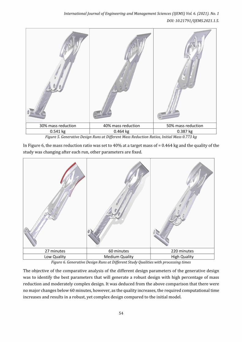
30% mass reduction 40% mass reduction 50% mass reduction
0.541 kg 0.464 kg 0.387 kg Figure 5. Generative Design Runs at Different Mass Reduction Ratios, Initial Mass 0.773 kg
In Figure 6, the mass reduction ratio was set to 40% at a target mass of = 0.464 kg and the quality of the
study was changing after each run, other parameters are fixed.
27 minutes 60 minutes 220 minutes
Low Quality Medium Quality High Quality Figure 6. Generative Design Runs at Different Study Qualities with processing times
The objective of the comparative analysis of the different design parameters of the generative design
was to identify the best parameters that will generate a robust design with high percentage of mass
reduction and moderately complex design. It was deduced from the above comparison that there were
no major changes below 60 minutes, however, as the quality increases, the required computational time
increases and results in a robust, yet complex design compared to the initial model.

International Journal of Engineering and Management Sciences (IJEMS) Vol. 6. (2021). No. 1
DOI: 10.21791/IJEMS.2021.1.5.
55
The fourth step was to investigate the conventional manufacturing methods for mechanical pedals and
compare the finite element analysis of these to the original designed pedal. The most common methods
of manufacturing the mechanical pedal are either welding or forging. To this end, the mechanical pedal
model that are based on the conventional methods of manufacturing such as welding, or forging are
given in the Figures below.
Figure 7. Redesign of a forged (left) and welded (right) mechanical pedal
Furthermore, the redesign of the above parts (forged and welded) was done again, keeping in view the
key features of the generative designs that were previously conducted. These key features highlighted
by the generative designs aimed to reduce the mass of the original pedal design. These key design
features were incorporated in the new pedal designs that can be manufactured by the conventional
methods such as forging, casting and welding. This is especially useful keeping in mind the costs and
complexity associated with the use of additive manufacturing for the designs suggested by the
generative design runs of solid edge. Given below in Figure 8 and 9 are the conceptual redesigned pedals
that have the incorporated features of the generative designs with the reduced mass and appropriate
factor of safety with conventional manufacturing methods in mind.
The first pedal redesign (concept redesign 1) had a mass of 0.470 kg (39% mass reduction) and factor
of safety value of 1.59, which was based on the manufacturing process of casting and welding. This
design is indicated in the Figure 8 along with its respective stress distribution profile.
Figure 8. Concept redesign 1 with the stress distribution

International Journal of Engineering and Management Sciences (IJEMS) Vol. 6. (2021). No. 1
DOI: 10.21791/IJEMS.2021.1.5.
56
The second pedal redesign (concept redesign 2) had a mass of 0.458 kg (40% mass reduction) and factor
of safety value of 1.63, which was based on the manufacturing process of casting, and welding. This
design is indicated in the Figure 9 along with its respective stress distribution profile.
Figure 9. Concept redesign 2 and the stress distribution
3. Conclusions
The main objective was to redesign the mechanical pedal such that the mass of the pedal is reduced by
using generative design as a guidance tool. First the mesh sensitivity analysis and finite element analysis
of a standard pedal design, using the material as Al-5050, were conducted to help identify the
appropriate mesh size and factor of safety for the model. Then generative designs for the mechanical
pedal were conducted using specific design parameters such as percentage mass reduction, required
factor of safety and an appropriate quality. The resulting generative design runs highlighted the key
features in the pedal design that would help to reduce the mass by about 40% and maintain a factor of
safety of approximately 1.5. These key features were incorporated in redesigned pedal models, while
keeping in mind the conventional methods of manufacturing such as casting, forging, welding, and
drawing. These redesigned parts were then analysed using finite element analysis to avoid any stress
concentrations and fractures while keeping all the stresses in the allowable region. The finite element
analysis of the redesigned mechanical pedal helps to shortlist the design which has the highest factor of
safety with maximum mass reduction. This design can be chosen as the most appropriate model for
manufacturing mechanical pedals that are light weight, mechanically strong and robust in nature.

International Journal of Engineering and Management Sciences (IJEMS) Vol. 6. (2021). No. 1
DOI: 10.21791/IJEMS.2021.1.5.
57
References
[1] J. M. Snyder, J. T. Kajiya, and H. B. Jovanovicli, Generative Modeling For Symbolic Shape Design Using
Interval Analysis. 1992.
[2] H. Li and R. Lachmayer, “Automated exploration of design solution space applying the generative
design approach,” Proc. Int. Conf. Eng. Des. ICED, vol. 2019-Augus, no. August, pp. 1085–1094, 2019, doi:
10.1017/dsi.2019.114.
[3] S. G. Shina, Concurrent Engineering and Design for Manufacture of Electronics Products. 1991.
[4] M. McKnight, “Generative Design: What it is? How is it being used? Why it’s a game changer,” KnE
Eng., vol. 2, no. 2, pp. 176–181, 2017, doi: 10.18502/keg.v2i2.612.
[5] D. Vlah, R. Žavbi, and N. Vukašinović, “Evaluation of Topology Optimization and Generative Design
Tools As Support for Conceptual Design,” Proc. Des. Soc. Des. Conf., vol. 1, pp. 451–460, 2020, doi:
10.1017/dsd.2020.165.
[6] J. GAVAČOVÁ, M. VEREŠ, and M. GRZNÁR, “COMPUTER AIDED GENERATIVE DESIGN OF
AUTOMOTIVE SHAPED COMPONENTS,” ACTA Teh. CORVINIENSIS – Bull. Eng., pp. 19–22, 2014.
[7] J. Gulanová, L. Gulan, M. Forrai, and M. Hirz, “Generative engineering design methodology used for
the development of surface-based components,” Comput. Aided. Des. Appl., vol. 14, no. 5, pp. 642–649,
2017, doi: 10.1080/16864360.2016.1273581.
[8] A. Peñaherrera, “Generative Design Optimization Process for Developing an E-bike Frame Using
SolidThinking Inspire,” UNIVERSIDAD SAN FRANCISCO DE QUITO, 2019.
[9] A. Joakim, “DESIGN OPTIMIZATION OF A CONNECTING ROD FOR INTERNAL COMBUSTION
ENGINE Presented to the Department of Mechanical and Aerospace Engineering California State
University , Long Beach In Partial Fulfillment of the Requirements for the Degree Master of Science,”
California State University, 2020.
[10] S. Bagassi, F. Lucchi, F. De Crescenzio, and F. Persiani, “Generative design: Advanced design
optimization processes for aeronautical applications,” 30th Congr. Int. Counc. Aeronaut. Sci. ICAS 2016,
pp. 1–7, 2016.
[11] S. Khan, E. Gunpinar, and B. Sener, “GenYacht: An interactive generative design system for
computer-aided yacht hull design,” Ocean Eng., vol. 191, pp. 1–16, 2019, doi:
10.1016/j.oceaneng.2019.106462.
[12] D. Huri and T. Mankovits, “Automotive rubber part design using machine learning,” IOP Conf. Ser.
Mater. Sci. Eng., vol. 659, no. 1, 2019, doi: 10.1088/1757-899X/659/1/012022.
[13] D. Huri and T. Mankovits, “Parameter selection of local search algorithm for design optimization
of automotive rubber bumper,” Appl. Sci., vol. 10, no. 10, 2020, doi: 10.3390/app10103584.
[14] Giraud-Moreau, Laurence, and Pascal Lafon. "A comparison of evolutionary algorithms for
mechanical design components." Engineering Optimization 34.3 (2002): 307-322.

International Journal of Engineering and Management Sciences (IJEMS) Vol. 6. (2021). No. 1
DOI: 10.21791/IJEMS.2021.1.5.
58
[15] Krish, Sivam. "A practical generative design method." Computer-Aided Design 43.1 (2011): 88-
100.
[16] Toptas, Ersin. "Innovative approach to the design of mechanical parts." Journal of Mechatronics
and Artificial Intelligence in Engineering 1.1 (2020): 14-20.
[17] Mačužić, Slavica, et al. "Pedal force determination respect to ride comfort." IOP Conference Series:
Materials Science and Engineering. Vol. 252. No. 1. IOP Publishing, 2017.