general technical specification and execution procedures ...shaghool.ir/files/code490en-1.pdf ·...
TRANSCRIPT

Islamic Republic of Iran
Vice Presidency for Strategic Planning and Supervision
General Technical Specification and Execution Procedures for Transmission
and Subtransmission Networks Fittings, Hardware and Accessories at
HV Substations
NO: 490 - 1
Energy Ministry - Tavanir Co.Power Industry Technical Criteria Project www.tavanir.ir
Office of Deputy for Strategic Supervision Bureau of Technical Execution Systemhttp://tec.mporg.ir


CONNTENTS Description PAGE 1- General requirements ................................................................................................... 3 2- Detailed requirements.................................................................................................... 4
2-1- Design................................................................................................................... 4 2-2- Fabrication ........................................................................................................... 4 2-3- Materials............................................................................................................... 5 2-3-1- Metallic materials.............................................................................................. 5 2-3-2- Non- metallic materials..................................................................................... 5 2-4- Welding ................................................................................................................ 6 2-5- Dimensions and tolerances................................................................................... 6 2-6- Protection against corrosion ................................................................................. 6 2-7- Marking ................................................................................................................ 7
2-7-1- Fittings used as individual components with castings method............................... 7 2-7-2- Fittings used as individual components with forgings method .............................. 7 2-7-3- Links and plates...................................................................................................... 7 2-7-4- Assemblies of fittings ............................................................................................. 7 2-7-5- Conductor compression fittings.............................................................................. 7
2-8- Catalogue numbers and drawings..................................................................................... 8 2-9- Packaging and shipment................................................................................................... 8
3- Requirement for specified fittings ................................................................................. 9 3-1- Insulator set fittings and earth wire fittings.......................................................... 9 3-2- Suspension clamps ............................................................................................... 9 3-3- Fittings for jointing, terminating and repairing conductor.................................. 10
3-3-1- General .................................................................................................................. 10 3-3-2- Flexible connectors................................................................................................ 11 3-3-3- Clamped connectors ............................................................................................. 11 3-3-4- Crimped connectors............................................................................................... 11 3-3-5- Bus support clamps .............................................................................................. 12
3-4- Bolts, nuts and washers ....................................................................................... 12 3.5. Terminal connecter .............................................................................................. 12 3-6- Insulator protective fittings ................................................................................. 13 3-7- Spacers ................................................................................................................ 13
4. Tests ....................................................................................................................15 5- Inspection............................................................................................................18 6- Drawing and documents .....................................................................................18
6-1- Documents to be given by tendered .................................................................... 18 6-2- Documents to be given by contractor/ supplier................................................... 18


General Requirements
1
Technical Specification for Fittings, Hardware and
Accessories at HV Substations

Technical Specification for Fittings, Hardware and Accessories at HV Substations
2
General Requirements
3
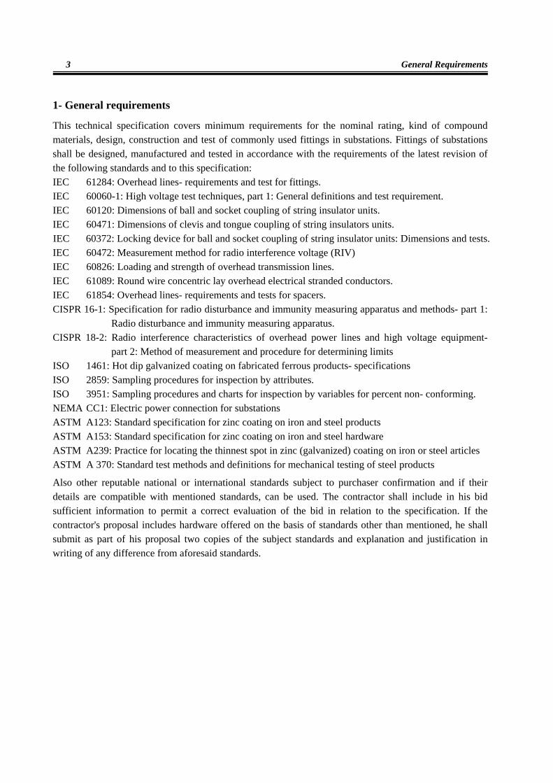
1- General requirements
This technical specification covers minimum requirements for the nominal rating, kind of compound materials, design, construction and test of commonly used fittings in substations. Fittings of substations shall be designed, manufactured and tested in accordance with the requirements of the latest revision of the following standards and to this specification: IEC 61284: Overhead lines- requirements and test for fittings. IEC 60060-1: High voltage test techniques, part 1: General definitions and test requirement. IEC 60120: Dimensions of ball and socket coupling of string insulator units. IEC 60471: Dimensions of clevis and tongue coupling of string insulators units. IEC 60372: Locking device for ball and socket coupling of string insulator units: Dimensions and tests. IEC 60472: Measurement method for radio interference voltage (RIV) IEC 60826: Loading and strength of overhead transmission lines. IEC 61089: Round wire concentric lay overhead electrical stranded conductors. IEC 61854: Overhead lines- requirements and tests for spacers. CISPR 16-1: Specification for radio disturbance and immunity measuring apparatus and methods- part 1:
Radio disturbance and immunity measuring apparatus. CISPR 18-2: Radio interference characteristics of overhead power lines and high voltage equipment-
part 2: Method of measurement and procedure for determining limits ISO 1461: Hot dip galvanized coating on fabricated ferrous products- specifications ISO 2859: Sampling procedures for inspection by attributes. ISO 3951: Sampling procedures and charts for inspection by variables for percent non- conforming. NEMA CC1: Electric power connection for substations ASTM A123: Standard specification for zinc coating on iron and steel products ASTM A153: Standard specification for zinc coating on iron and steel hardware ASTM A239: Practice for locating the thinnest spot in zinc (galvanized) coating on iron or steel articles ASTM A 370: Standard test methods and definitions for mechanical testing of steel products
Also other reputable national or international standards subject to purchaser confirmation and if their details are compatible with mentioned standards, can be used. The contractor shall include in his bid sufficient information to permit a correct evaluation of the bid in relation to the specification. If the contractor's proposal includes hardware offered on the basis of standards other than mentioned, he shall submit as part of his proposal two copies of the subject standards and explanation and justification in writing of any difference from aforesaid standards.

Technical Specification for Fittings, Hardware and Accessories at HV Substations
4
On the basis of this information, the acceptability of the proposed hardware will be determined by the owner.
2- Detailed requirements
2-1- Design
The fittings shall be designed so as to: - Avoid damaging the conductor under service conditions. - Withstand the mechanical loads relevant to installation, maintenance and service, the designed
service current including short circuit current, the service temperatures and environmental circumstances.
- Withstand against seismic forces. - Ensure that individual components are secured against becoming loose in service. - Have limited corona effects. - Prevent from point or linear connection between connections.
Surfaces of compression fittings in contact with the conductor or earth wire shall be protected from becoming contaminated before installation. Brittleness of finished parts shall be avoided by adopting suitable materials and manufacturing process. All hardware designed with a pin and cotter key so that the cotter key would be subject to wear shall include a bolt, nut and cotter key. Cotter keys for use with pins shall be brass or stainless steel. All cotter keys shall be hump type. Ends beyond the hump shall be pointed or cut diagonally and shall not project beyond the pins by more than 15mm. If dissimilar materials are used for the accessories suitable precaution shall be taken to minimize electrolytic action.
2-2- Fabrication
All hardware components shall be so fabricated and treated that there shall be no electrolytic action occurring between the accessories and the cables and between the various parts of the individual accessories.

Detailed Requirements
5
Surface shall be smooth, free from burs, lumps, dross and all edges and corners rounded. All plate, shapes and straps shall be neatly and accurately formed. Shearing or cutting shall be clean without ragged or drawn edges. Holes shall be clean and at right angle to the surface of the plates, shapes, or straps and free from any ridges or shoulders. Distortion due to heat stresses shall be corrected before galvanizing by methods that will not damage the material.
2-3- Materials
Fittings shall be made of any material suitable for the purpose and in accordance with ISO standards.
2-3-1- Metallic materials
The materials shall meet service life requirements and shall not be liable to intergranular or stress corrosion. They shall not cause corrosion of any other parts of the conductor or earth wire. The materials of compression fittings shall be capable of withstanding the cold working due to compression. Furthermore, the steel compression components shall also have a sufficient impact strength after the compression. Examples of suitable materials are the following:
- Aluminum or aluminum alloy - Galvanized steel - Galvanized malleable or ductile iron - Stainless steel - Copper and copper alloys
In accordance with the IEC 61284 recommendation, ISO standards for materials be used where they exist.
2-3-2- Non- metallic materials
Non- metallic materials employed shall have good resistance to ageing and be capable of withstanding service temperatures without detrimental change of properties. Materials shall have adequate resistance to the effects of ozone, ultra- violet radiation and air pollution over the whole range of the service temperature. Non- metallic materials shall not induce corrosion in materials which are in contact with them.

Technical Specification for Fittings, Hardware and Accessories at HV Substations
6
2-4- Welding
Aluminum alloys shall be welded by an inert gas shielded tungsten or inert gas shield arc process. Steel shall be welded by an arc process. During welding operating, parts shall be held by clamps or other suitable means to keep them in correct position. Welding surface shall be smooth and without overlaps of excessive under cutting. Rough surface slag, and splatter from welding shall be removed before galvanizing by grinding or sand blasting.
2-5- Dimensions and tolerances
The dimensions shall be shown on contract drawings. Particular regard shall be paid to those dimensions which involve interchangeability, correct assembly, and those for which gauge are specified. Reference shall be made to relevant standards, for example IEC 60120, 60372, and 60471. Tolerances applied to dimensions shall ensure that the fitting meet their specified mechanical and electrical requirements.
2-6- Protection against corrosion
All parts of insulator, conductor and earth wire fittings shall be either inherently resistant to atmospheric corrosion or be suitably protected against corrosion, such as can occur in transport, storage and in service. All ferrous parts which will be exposed to the atmosphere in service, except those made of appropriate stainless steel, shall be protected by hot dip galvanizing in accordance with ISO 1461 or other means giving equivalent protection. Minimum allowable thickness of zinc coating shall be in accordance with ASTM 123A or other reputable standards.
2-7- Marking
Marking shall ensure the system of traceability for each of the component parts of the fittings.

Marking
7
When practicable, and unless otherwise agreed between purchaser and manufacturer, fittings shall be clearly and indelibly marked as follows:
2-7-1- Fittings used as individual components with castings method
- Identification of fittings (reference number/ specified minimum failure load) - Manufacturer's identification - Date of manufacture (month and year) - Cast code
2-7-2- Fittings used as individual components with forgings method
- Identification of fittings (reference number/ specified minimum failure load) - Manufacturer's identification - Date of manufacture (month and year)
2-7-3- Links and plates
- Identification of fittings (reference number/ specified minimum failure load) - Manufacturer's identification - Date of manufacture (month and year)
2-7-4- Assemblies of fittings
- Identification (reference number/ specified minimum failure load) - Manufacturer's identification - Date of manufacture of individual items (month and year) - Conductor diameter range or conductor code (s), as agreed between purchaser and supplier - Fittings bolt installation torque (unless bolts breakaway torque are used)
2-7-5- Conductor compression fittings
- Identification (reference number/ specified minimum failure load) - Manufacturer's identification - Date of manufacture (month and year) - Conductor size or code name

Technical Specification for Fittings, Hardware and Accessories at HV Substations
8
- Compression die sizes - Length to be compressed
2-8- Catalogue numbers and drawings The contractor shall notify the owner of changes to catalogue items, catalogue numbers, or drawings of substations hardware and components to ensure that the owner has the up-to-date information. All change shall be described in writing, stating the purpose of changes, how they affect the product, and whether any of the physical or electrical properties have been altered in any way. The contractor shall submit two prints of preliminary drawings with his proposal. For any item not shown fully dimensioned in the contractor's catalogue, the contractor shall submit fully dimensioned detail drawings with his proposal. Final drawings shall be submitted and approved before testing and delivery can commence. The contractor shall submit a schedule indicating when final drawings will be submitted for approval, and a schedule for submitting a test program, conducting the test program, and shipping the approved accepted material. Dimensions shown in catalogues and drawings will be in the metric system, but its equivalent in other systems shall mention. All required drawings shall be drawn to scale (preferably each 10 cm equals to 25 mm on drawings) and fully dimensioned. All items thereon shall be identified with appropriate nomenclatures as to size, type, rated strength, nominal phase to phase voltage specification as well as features and requirement as specified by the owner. Drawings shall show on one sheet all items to be furnished for an assembly, and shall include a complete bill of materials.
2-9- Packaging and shipment Hardware and accessory items shall be packaged in accordance with one of the following at the contractor's option:
- Package all like components together - Package all like assemblies together
In all cases all material to be shipped shall be properly packaged to protect it from damage in transit. Any articles that might otherwise be lost shall be boxed or wired in bundles and identified.

Requirement for Specified Fittings 9
All package shall clearly indicate the contents, and all markings shall be legible and weather proof. Manufacturer shall present instruction and manual of installation of hardware and accessories which is needed.
3- Requirement for specified fittings
3-1- Insulator set fittings and earth wire fittings For parts made of forged steel, holes which are under mechanical stress can be made by hot punching provided that the holes conform to tolerances on at least 70% of punched thickness. For parts made of forged steel, holes which are not under mechanical stress can be made by cold or hot punching without the aforementioned limits.
3-2- Suspension clamps
The conductor or the earth wire installed in the suspension clamps can be used bare or equipped with armour rods. The suspension clamps shall be so designed that the effect of vibration, both on the conductor or on the earth wire and on the clamps themselves, are minimized. The clamps shall be designed to avoid localized pressure or damage to the conductor or the earth wire. The suspension clamps shall have sufficient contact surface to avoid damage by fault currents. The wear resistance of the articulation assembly shall be sufficient to prevent deterioration in service. Magnetic losses shall not exceed the laid down value, if specified. The body of suspension clamps shall permit oscillation around a horizontal axis perpendicular to the conductor. The manufacturer shall provide the purchaser with the usage limits of the suspension clamps. For each type of clamp, the purchaser can choose between standard clamps or controlled slippage suspension clamps. In standard clamps, the slip load of the conductor or earth wire is not lower than a specified minimum slip load. In controlled slippage clamps, the slip load of the conductor remains between two values defined by mutual agreement between the purchaser and the supplier.

Technical Specification for Fittings, Hardware and Accessories at HV Substations
10
3-3- Fittings for jointing, terminating and repairing conductor
3-3-1- General
The value of carrying currying of current carrier fittings shall not less than of connected conductor in same temperature. For the specified short circuit current and duration, the temperature rise of the connectors shall not exceed that of the conductors they connect. Solder as well as additional material when aluminum welding, should be correctly proportioned to the conductors to be connected. Solder and additional material which without protection can cause dangerous corrosion, shall be protected by good manner. All materials in a connector shall be able to withstand temperatures from- 45° up to +100ºC without becoming brittle of loose their mechanical or electrical properties. Aluminum connectors shall be made of aluminum or aluminum alloy, free of copper with resistance to corrosion as near as possible to that of aluminum. The surface of the connector shall be factory made oxide free by girding, etching and application of special coating. Wherever a copper aluminum connection is made, the contact surface of the copper shall be tin-plated or appropriate bimetal sheath used to avoid electrolytic corrosion. Fittings used to electrical continuity connections shall meet the requirements of heat cycle tests. Fittings shall so design to maintain electrical resistance in connection point in allowable range to prevent from production of loss and heat. Those fittings with auxiliary eyes intended for use during construction or maintenance shall be marked with a specified minimum failure load stated by the manufacturer. All fittings shall be designed to minimize internal voids and to prevent the ingress or entrapment of moisture during service. Fittings may be provided with an oxide-inhibiting compound intended to reduce metal oxidation at metal-to metal electrical contact points. These compounds are commonly used in compression fittings to fill internal voids and to prevent ingress of water during service. Fittings shall be designed in such away that after installation, the initial contact area between the fitting and the conductor does not raise stresses which can lead to failure under conductor oscillation conditions. Fittings and connectors intended to connect conductors of two dissimilar materials shall be designed to avoid bimetallic corrosion.

Flexible Connectors 11
Fittings and connectors intended for the restoration of electrical and mechanical properties of a conductor shall have clearly defined manufacturer's instructions.
3.3.2. Flexible connectors Flexible connectors between tube and terminal shall have the minimum possible effect on the terminals as regard mechanical (tensile, bending and wrenching) stresses. Flexible connectors shall permit the movements and withstand against allowable stresses. Flexible connectors between aluminum tube and terminal shall effectively reduce mechanical swinging of the aluminum tube without any appreciable damage to the tube, and without any butt-action on the terminal. During short circuits, the tubes in flexible connector are subject to a short dynamic load. The tubes should therefore be supported so that no butt-shock can be transferred to the terminal on account of the tube acceleration as a result of this dynamic load. When a tube which joins two apparatuses by means of flexible connectors means shall be taken to prevent the tube from falling out of its support in the flexible connector. Flexible connectors shall allow downward bending of the tube due to ice weight and short circuits.
3-3-3- Clamped connectors Clamped connectors shall be provided with conductor grooves for each conductor. Clamped connectors between cables or cable and homogeneous conductor shall be provided with separate caps for the connected conductors. Parallel connectors for cables can be made with an common base plate and a common cap. Internal threads in bolted connectors shall have a higher tensile strength than the screw. It is understood that tightening breakages can take place in the screw without the internal threading breaking, and that the broken part of the threaded screw can be easily removed from the connector.
3-3-4- Crimped connectors Materials which is form crimped connectors shall be essential deformation which is designed for, without occurring any fracture. Crimped connectors as well as the installation tools shall be made so that maintain the mechanical and electrical qualities of the conductor and connector.

Technical Specification for Transmission Line Fitting, Hardware and Accessories
12
Crimped connectors shall be designed to prevent water penetration. If this cannot be prevented, then the drainage holes shall be provided. Crimped connectors shall be provided when possible with marks to indicate where crimping is to be carried out.
3-3-5- Bus support clamps The bus support clamps shall be so dimensioned that clashing between the aluminum tube and the clamp does not occur during short circuit. The bus support clamps shall not be notably heated by hystersis or eddy current losses. The bus support clamps for continuous tube shall allow unlimited movement of tube in its axial direction with respect to the clamp. The tubes shall be prevented from falling out of the flexible bus support clamps.
3-4- Bolts, nuts and washers Bolts, nuts and washers shall be of stainless steel or aluminum alloy with minimum resistant against corrosion and expansion coefficient equal to stainless steel which is specified in DIN standards. Bolts used to screw into aluminum parts shall be greased. Greasing shall be so carried out that water is prevented from entering the bottom threaded hole. Washers or any other fittings shall be of materials which don’t damage the surface when screwing and unscrewing. Flat washers shall be used under bolt heads to satisfactorily distribute the pressure. Bolts shall be used as clamping devices only and not as current carrying parts. Any locking methods which has to be adopted shall be detailed.
3.5. Terminal connecter High voltage terminal shall normally be of module plate type. Pin type is accepted as an alternative. The terminal shall be designed according to bending moment owing to wind load or earthquake force together with horizontal pull of the high voltage line conductor. Module plate terminals shall be designed according to primary current level as following dimensions: Terminals for maximum rated current upto 1600 A shall be designed as plate of 75×75×15 mm (L×W×T). The plate should have 4 holes of 14 mm diameter with 40±0.5 mm as distance between holes center. Also the distance between plate edge and hole center should be 17.5 mm. Terminals for maximum rated current upto 3150 A shall be designed as plate of 125×125×35 mm (L×W×T). The plate should have 4 or 9 holes of 14 mm diameter and center to center distance of 40±0.5 mm for two holes side by side.

Insulator Protective Fittings 13
Pin type terminals shall be designed according to the following cases: Terminals for maximum rated current upto 1600 A shall be designed as a pin of 125 mm length and having 30±0.15 mm diameter. Terminals for maximum rated current upto 3150 A shall be designed as a pin of 125 mm length and having 60±0.2 mm diameter. Terminals of copper (Cu) or a copper alloy shall be tinned to a thickness of minimum of 50 micro meters. A copper alloy which is sensitive to season cracking shall not be used. Terminals of aluminum or an aluminum alloy shall not be treated. An alloy sensitive to season cracking, shall not be used. A module plate terminal of aluminum or aluminum alloy shall have a hardness of minimum 750 N/mm2.
3-6- Insulator protective fittings Should steel or aluminum tubes be used for insulator protective fittings, both the internal and external surfaces of the tubes shall be hot dip galvanized. When the tube is sealed after galvanizing, the quality of the internal surface shall be agreed between purchaser and supplier. For insulator protective fittings designed to protect insulator sets against damage caused by power arcs (arcing horns, arcing rings, rings), the short circuit current conditions shall be stated by the customer in the order. The protective fittings shall be designed in such a way as not to be subject to breakage through fatigue due to vibration caused by the wind. The insulator protective fittings shall withstand a static mechanical load agreed upon between supplier and purchaser.
3-7- Spacers The spacer shall be designed as to:
- Maintain subconductor spacing (at spacer locations), within any prescribed limits, under all conditions of service excluding short- circuit currents.
- Prevent, in subspans between spacers, physical contact between subconductors, except during the passage of short circuit currents when the possibility of contact is accepted provided that the specified spacing is restored immediately following fault clearance.
- Withstand mechanical loads imposed on the spacer during installation, maintenance and service (including short circuit condition) without any component failure or unacceptable permanent deformation.
- Avoid damage to the subconductor under specified service conditions. - Be free from unacceptable levels of corona and radio interference under specified service
conditions.

Technical Specification for Transmission Line Fitting, Hardware and Accessories
14
- Be suitable for safe and easy installation. For the bolted and latching clamp the design shall retain all parts when opened for attachment to the conductor.
- Ensure that individual components will not become loose in service. - Be capable of being removed and re-installed on the subconductors without damage to the spacer
or subconductors. - Maintain its function over the entire service temperature range. - Avoid audible noise.
Other desirable characteristics, which are not essential to the basic function of the spacer but which may be advantageous to the purchaser, include:
- Verification of proper installation from the ground - Ease of installation and removal from energized lines
The conductivity of the various non-metallic components shall be such that when properly installed: - Potential differences between metallic components do not cause damage due to discharge - Any current flow between subconductors does not degrade spacer materials
Spacer mass and significant dimensions, including appropriate tolerances, shall be shown on contract drawings. Tolerances applied to the mass and to the dimensions should ensure that the spacers meet their specified mechanical and electrical requirements. The spacers shall be free of defects and irregularities. All outside surfaces shall be smooth and all edges and corners well-rounded. In fitting marking, correct position of the top of the spacer (for example arrows pointing upward), if necessary, shall also be provided. The supplier shall provide clear and complete description of the installation procedure and, if required, the in-span location of the spacers. The supplier shall make available any special installation tool that is required.
Tests 15
4. Tests Prior to the owner acceptance and approval of the hardware and accessories, the contractor shall furnish sufficient and satisfactory proof of the performance of the hardware undergoing the electrical and mechanical tests. Tests shall be conducted in laboratories having ample facilities to prove the fulfillment of the basic requirements as defined herein. Prior to performing such tests, the contractor, shall accurately indicate and describe, in the form of photographs, drawings, or writing, the proposed test facilities, test schedule, and procedure for preparing, measuring, recording, and applying voltage or mechanical load. During the course of testing, material samples shall be fully equal to and representative of those which the contractor intents to supply. If any modification is made after testing, the contractor shall explain, justify and retest, the owner's discretion, the modified item to the owner's satisfaction. Any change in material, design, and detail drawings after approval by the owner will only be permitted after written approval of the changes is given by the owner. All type, sample and routine tests on hardware and accessories of substations shall be done in accordance with the latest revision of IEC 61284, IEC 61897 and IEC 61854 and mentioned references on those. List of relevant tests on different type of fittings and accessories are given in table 1 and 2. For the fittings which are not covered in this standard one can refer to reputable international standard in agreed between purchaser and manufacturer.

Technical Specification for Transmission Line Fitting, Hardware and Accessories
16
Table 1- Tests on fittings according to IEC 61284 Insulator protective
fittings (1) Repair sleeve Partial tension fittings Tension joints and tension clamps Suspension clamps Insulator set fittings and
earth wire fittings Routine
tests Sample
tests Type tests
Routine tests
Sample tests
Type tests
Routine tests
Sample tests
Type tests
Routine tests
Sample tests
Type tests
Routine tests
Sample tests
Type tests
Routine tests
Sample tests
Type tests
Test
3 2 3 2 3 2 3 2 3 2 3 2 Visual examination
3 3 3 3 3 3 Dimensional and material verification
- 3 - - 3 - 3 - 3 - 3 - 3 Hot dip galvanizing
3 3 3 - - - - 3 3 3 3 3 3 3 3 3 3 3 Non- destructive testing
3 3 3 - - - - - - - 3 3,4 3,4 Damage and failure load test
- - - - - - - - - - - - - - - - Slip test
- - - - - - - - - - 2 - 2 - - - Clamp bolt tightening test
- - - - - - - - - - - - - Tensile test
- - - - - - - - - 3,4 3 - - - - 3 Damage and failure load test of the attachment point used during erection
- - - - - - - - - - - 3 - - 3 - - - Magnetic losses test
- - - - - - - - 5 - - 5 - - - - - - Heat cycle tests
- - 3,6 - - 3 - - 3 - - 3 - - 3,6 - - 3,6 Corona and RIV test
1- Includes electrical gradient devices Note: The gray places means the test shall be performed. 2- Inspection by attributes only 3- By agreement between purchaser and supplier 4- Only as regards damage load test 5- Only for current- carrying joints 6- Only in connection with the complete insulator set

Tests 17
Table 2- Tests on fittings according to IEC 61854
Rigid spacer Flexible spacer Spacer damper Routine
tests Sample
tests Type tests
Routine tests
Sample tests
Type tests
Routine tests
Sample tests
Type tests
Test
1 1 1 Visual examination 1 1 1 Verification of dimensions, material and mass - 2 2 - 2 2 - 2 2 Corrosion protection tests 1 1 1 1 1 1 1 1 1 Non- destructive tests - 1 - 1 - 1 Clamp slip tests - - - Breakaway bolt test - - - Clamp bolt tightening test
- 1 - 1 - 1 Simulated short- circuit current test and compression and tension tests
- - - - 1 1 - 1 Characterization of the elastic and damping properties - - - - 1 - 1 Flexibility tests - - - - - 1 - - 1 Fatigue tests - - - - 1,2 2 - 1 Tests to characterize elastomers - - - - - - - Corona and radio interference voltage (RIV) tests - - - 1,2 2 - 1 Electrical resistance test - - 1,2 - - 1,3 - - 1 Aeolian vibration - - - - 1 - - 1 Subspan oscillation
1- Additional tests which shall perform subject to purchaser request. Note: The gray places means the test shall be performed. 2- If applicable. 3- When use in conjunction with vibration dampers. 4- Not applicable for earth wire dampers.

Technical Specification for Transmission Line Fitting, Hardware and Accessories
18
5- Inspection The manufacturer shall afford the purchaser all necessary and sufficient testing facilities to satisfy him. Whether the test results are positive or not, the purchaser can reject factory production if during of erection time, the fitting specification have not adoption with necessary requirement or working not well in service.
6- Drawing and documents
6-1- Documents to be given by tendered
- Filled fitting schedule II - Catalog and technical pamphlets - Detailed summary of exceptions to tender specification - Reference list - List of spare parts - List of special tools - Success of type tests documents - Packing, shipping, warehousing, installation and maintenance instruction manuals
6-2- Documents to be given by contractor/ supplier The design, manufacturing, factory testing, packing, marking, shipping, warehousing, erection, site testing and operation document, electrical drawing and manual of fitting shall be submitted but not limited to the following: - Calculation sheets to establish adequacy of fittings in any respect (in clouding short circuit
calculations, allowable mechanical tension and …) - Details of packing, shipment and warehousing - Report of tests and certificate - Erection, operation and maintenance manual instruction - Drawings which depict dimension, shape, shipment type, weight, type and other specification - Details of installation and erection of fitting - Monthly progress report - Time schedule - List of drawings - List of equipment

Tables I,II
19
SCHEDULE FITTING (I) RATING AND CHARACTERISTICS OF FITTING
TECHNICAL SPECIFICATION FOR SYSTEMS WITH FOLLOWING NOMINAL VOLTAGES ITEM DESCRIPTION
63/66 kV 132 kV 230 kV 400 kV 1 Particulars of systems
1-1 Nominal system voltage kV 63/66 132 230 400 1-2 Highest system voltage kV 72.5 145 245 425 1-3 Nominal system frequency Hz 50 50 50 50 1-4 Specification of phase conductors of substation
(stranded, tubular, material, rated current and dimension specification) * * * *
1-5 Specification of guard wires of substation (material and dimension specification) * * * *
1-6 Specification of damping wire of tubular conductors (material and dimension specification) * * * *
1-7 Max. allowable temperature of fittings and connected conductors to them in rated current and short circuit current conditions °C * * * *
1-8 Max. short circuit current of different level of voltage of substation kApeak * * * *
1-9 Max. short circuit duration sec * * * * 1-10 Radio interference voltage level in 1MHz
frequency and 10% over transmission line highest voltage Vµ * * * *
2 Service condition 2-1 Max. ambient temperature °C 40/45/50/55 40/45/50/55 40/45/50/55 40/45/50/55 2-2 Min. ambient temperature °C -40/-35/-30/-25 -40/-35/-30/-25 -40/-35/-30/-25 -40/-35/-30/-25 2-3 Seismic acceleration g 0.2/0.25/0.3/0.35 0.2/0.25/0.3/0.35 0.2/0.25/0.3/0.35 0.2/0.25/0.3/0.35 2-4 Max. wind velocity m/s 30/40/45 30/40/45 30/40/45 30/40/45 2-5 Wind velocity at ice condition m/s 20 20 20 20 2-6 Ice coating thickness 5/10/20/25 5/10/20/25 5/10/20/25 5/10/20/25 2-7 Pollution level
Low/medium/high/ very high/special
Low/medium/high/ very high/special
Low/medium/high/ very high/special
Low/medium/high/ very high/special

Technical Specification for Transmission Line Fitting, Hardware and Accessories
20
2-8 Altitude above sea level m 1000/1500/2000/2500 1000/1500/2000/2500 1000/1500/2000/2500 1000/1500/2000/2500 2-9 Relative humidity 90/95/more than 95 90/95/more than 95 90/95/more than 95 90/95/more than 95
SCHEDULE FITTING (I)
RATING AND CHARACTERISTICS OF FITTING TECHNICAL SPECIFICATION FOR SYSTEMS WITH FOLLOWING NOMINAL
VOLTAGES ITEM DESCRIPTION
63/66 kV 132 kV 230 kV 400 kV 3 Insulator set fittings
3-1 Suspension insulators 3-1-1 Min. rated tensile strength of insulator set kN * * * * 3-1-2 Number of strings * * * * 3-1-3 Specification and number of insulator unit in each string * * * * 3-1-4 Suspension clamp specification (quantity, tensile strength, slip
strength and conductor size) * * * * 3-1-5 Protective fittings and corona rings (arc distance and material) * * * * 3-2 Tension insulators
3-2-1 Min. rated tensile strength of insulator set kN * * * * 3-2-2 Number of strings * * * * 3-2-3 Specification and number of insulator unit in each string * * * * 3-2-4 Tension clamp specification (quantity, tensile strength and
conductor size) * * * * 3-2-5 Protective fittings and corona rings (are distance and material) * * * *
4 Guard wire fittings 4-1 Min. rated tensile strength of insulator set kN * * * * 4-2 Number of strings * * * * 4-3 Specification and number of insulator unit in each string * * * * 4-4 T connector material * * * *
* * *

Tables I,II
21
SCHEDULE FITTING (I) RATING AND CHARACTERISTICS OF FITTING
TECHNICAL SPECIFICATION FOR SYSTEMS WITH FOLLOWING NOMINAL VOLTAGES ITEM DESCRIPTION
63/66 kV 132 kV 230 kV 400 kV 5 Busbar and conductor fitting
5-1 Conductor support 5-1-1 Material * * * * 5-1-2 Rated bending strength * * * * 5-1-3 Connection type (bolt and nuts, press or weld) kN.m * * * * 5-2 Connectors
5-2-1 Material * * * * 5-2-2 Min. rated tensile strength kN * * * * 5-2-3 Min. rated bending strength for terminal and tubular conductor kN.m * * * * 5-2-4 Connection type (both and nuts, press or weld) * * * * 5-3 Tubular conductor end cap
5-3-1 Type of connection to conductor (both and nuts, press or weld) * * * * 5-3-2 Shape (spherical or smooth) kg * * * * 5-3-3 Material * * * * 5-4 Spacers
5-4-1 Type (solid, flexible and with damper) * * * * 5-4-2 Material * * * * 5-4-3 Connection type (bolt and nuts, press or weld) * * * *

Technical Specification for Transmission Line Fitting, Hardware and Accessories
22
SCHEDULE FITTING (I) RATING AND CHARACTERISTICS OF FITTING
TECHNICAL SPECIFICATION FOR SYSTEMS WITH FOLLOWING NOMINAL VOLTAGES ITEM DESCRIPTION
63/66 kV 132 kV 230 kV 400 kV 5-5 Temporary earthing connection clamps
5-5-1 Connection type (bolt and nut, press or weld) * * * * 5-5-2 Material * * * * 5-6 Post insulator arcing rings
5-6-1 Material * * * * 5-6-2 Specification of post insulator which arcing rings is sued * * * *
* These quantities will be specified by engineer

Tables I,II
23
SCHEDULE FITTING (II) RATED VALUES AND TECHNICAL SPECIFICATION OF FITTING
TECHNICAL SPECIFICATION FOR SYSTEMS WITH FOLLOWING NOMINAL VOLTAGES ITEM DESCRIPTION
63/66 kV 132 kV 230 kV 400 kV 1 General
1-1 Max. design ambient temperature °C 1-2 Min. design ambient temperature °C 1-3 Pollution level 1-4 Design altitude above sea level m 1-5 Max. design wind velocity m/s 1-6 Max. design wind in ice condition m/s 1-7 Max. design ice thickness mm 1-8 Permissible relative humidity % 1-9 Design seismic acceleration m/s2
1-10 Max. design R.I.V level in 1 MHz and 15% over transmission highest voltage µV
1-11 Max. design temperature for fitting, and connected conductors in rated and short circuit current °C
1-12 Max. short circuit current kA 1-13 Documents (test reports / outline drawings / catalogues /
maintenance installation manuals / reference list / list of spare parts) (yes/No)

Technical Specification for Transmission Line Fitting, Hardware and Accessories
24
SCHEDULE FITTING (II) RATING AND CHARACTERISTICS OF FITTING
TECHNICAL SPECIFICATION FOR SYSTEMS WITH FOLLOWING NOMINAL VOLTAGES ITEM DESCRIPTION
63/66 kV 132 kV 230 kV 400 kV 2 Insulator set fittings
2-1 Suspension insulators 2-1-1 Rated tensile strength kN 2-1-2 Number of strings 2-1-3 Specification and number of insulator unit in each string 2-1-4 Suspension clamp specification (manufacturers name and
country, manufacturers type and designation, rated tensile strength, min. and max. slip strength weight, material, conductor size and quantity)
2-1-5 Protective fittings and corona rings (manufacturers name and country, manufacturers type and designation, weight, arc distance, quantity, ring diameter, allowable fault current and mounting places)
2-1-6 Insulator set suspension fitting specification (manufacturers name and country, manufacturers type and designation, material and total weight)
2-2 Suspension insulators 2-2-1 Rated tensile strength kN 2-2-2 Number of strings 2-2-3 Specification and number of insulator unit in each string 2-2-4 Suspension clamp specification (manufacturers name and
country, manufacturers type and designation, rated tensile strength, min. and max. slip strength weight, material, conductor size and quantity)
2-2-5 Protective fittings and corona rings (manufacturers name and country, manufacturers type and designation, weight, arc distance, quantity, ring diameter, allowable fault current and mounting places)
2-2-6 Insulator set suspension fitting specification (manufacturers
Tables I,II
25
name and country, manufacturers type and designation, material and total weight)
Technical Specification for Transmission Line Fitting, Hardware and Accessories
26
SCHEDULE FITTING (II) RATING AND CHARACTERISTICS OF FITTING
TECHNICAL SPECIFICATION FOR SYSTEMS WITH FOLLOWING NOMINAL VOLTAGES ITEM DESCRIPTION
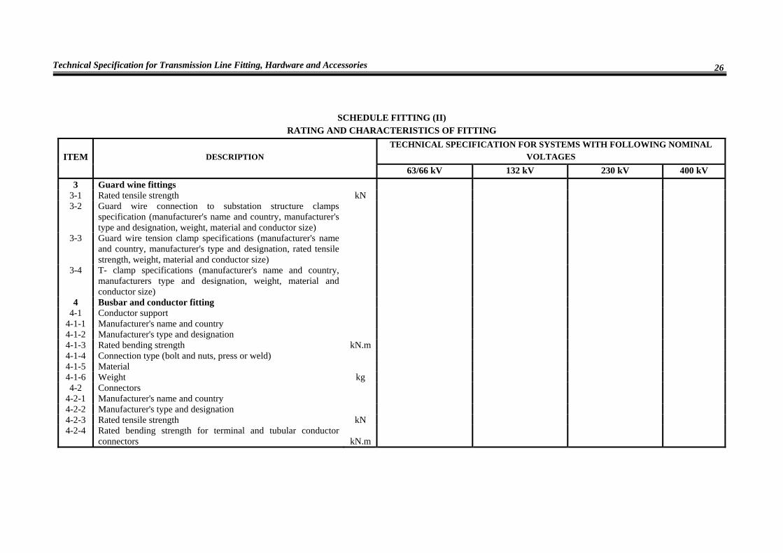
63/66 kV 132 kV 230 kV 400 kV 3 Guard wine fittings
3-1 Rated tensile strength kN 3-2 Guard wire connection to substation structure clamps
specification (manufacturer's name and country, manufacturer's type and designation, weight, material and conductor size)
3-3 Guard wire tension clamp specifications (manufacturer's name and country, manufacturer's type and designation, rated tensile strength, weight, material and conductor size)
3-4 T- clamp specifications (manufacturer's name and country, manufacturers type and designation, weight, material and conductor size)
4 Busbar and conductor fitting 4-1 Conductor support
4-1-1 Manufacturer's name and country 4-1-2 Manufacturer's type and designation 4-1-3 Rated bending strength kN.m 4-1-4 Connection type (bolt and nuts, press or weld) 4-1-5 Material 4-1-6 Weight kg 4-2 Connectors
4-2-1 Manufacturer's name and country 4-2-2 Manufacturer's type and designation 4-2-3 Rated tensile strength kN 4-2-4 Rated bending strength for terminal and tubular conductor
connectors kN.m
Tables I,II
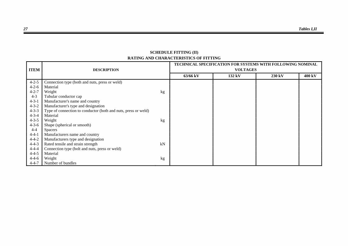
27
SCHEDULE FITTING (II) RATING AND CHARACTERISTICS OF FITTING
TECHNICAL SPECIFICATION FOR SYSTEMS WITH FOLLOWING NOMINAL VOLTAGES ITEM DESCRIPTION
63/66 kV 132 kV 230 kV 400 kV 4-2-5 Connection type (both and nuts, press or weld) 4-2-6 Material 4-2-7 Weight kg 4-3 Tubular conductor cap
4-3-1 Manufacturer's name and country 4-3-2 Manufacturer's type and designation 4-3-3 Type of connection to conductor (both and nuts, press or weld) 4-3-4 Material 4-3-5 Weight kg 4-3-6 Shape (spherical or smooth) 4-4 Spacers
4-4-1 Manufacturers name and country 4-4-2 Manufacturers type and designation 4-4-3 Rated tensile and strain strength kN 4-4-4 Connection type (bolt and nuts, press or weld) 4-4-5 Material 4-4-6 Weight kg 4-4-7 Number of bundles

Technical Specification for Transmission Line Fitting, Hardware and Accessories
28
SCHEDULE FITTING (II) RATING AND CHARACTERISTICS OF FITTING
TECHNICAL SPECIFICATION FOR SYSTEMS WITH FOLLOWING NOMINAL VOLTAGES ITEM DESCRIPTION
63/66 kV 132 kV 230 kV 400 kV 4-5 Temporary earthing connection clamps
4-5-1 Manufacturers name and country 4-5-2 Manufacturers type and designation 4-5-3 Connection type (bolt and nut, press or weld) 4-5-4 Material 4-5-5 weight kg 4-6 Post insulator arcing rings
4-6-1 Manufacturers name and country 4-6-2 Manufacturers type and designation 4-6-3 Specification of post insulator which arcing rings is sued 4-6-4 Material 4-6-5 weight kg