general specification for building 2012 edition ... · the 2012 edition (incorporating corrigendum...
TRANSCRIPT

General Specification for Building
2012 Edition (Incorporating Corrigendum No. GS 2012-02)
The 2012 edition (incorporating Corrigendum No. GS 2012-02) of the General
Specification for Building has incorporated updates and revisions to the 2012 edition (incorporating Corrigendum No. GS 2012-01). Please refer to the summary of major changes for the revisions.
Electronic version of this 2012 edition (incorporating Corrigendum No. GS 2012-02) can be viewed on the ArchSD Internet homepage.
In view of the revisions and new additions, there will be an introductory period of about 2 months in preparation for full implementation of this 2012 edition (incorporating Corrigendum No. GS 2012-02) as contract document by 1 August 2016. In summary,
For tenders to be invited on or after 1 August 2016, this 2012 edition (incorporating
Corrigendum No. GS 2012-02) shall be used.
Existing contracts (including contracts using previous editions tendered before 1 August 2016) will not be affected.

1/59
ARCHITECTURAL SERVICES DEPARTMENT
GENERAL SPECIFICATION FOR BUILDING
2012 EDITION
Corrigendum No. GS 2012 – 02
(Effective from 1 August 2016)
The follow clauses and indexes are amended in the above edition of General Specification for Building.
Amendments to Section 1
Quality generally
1.46 Materials and workmanship shall generally be consistent with good
building practice in Hong Kong and shall comply with the Regulations and
the relevant BS, BS EN or CP unless otherwise specified and/or approved.
Tests 1.56 Make tests on materials and workmanship as specified or as instructed by
the SO.
Provide test samples under the supervision of the SO and carry out tests by
the Public Works Laboratories (PWL) or when required, by an independent
body accredited by the Hong Kong Laboratory Accreditation Scheme
(HOKLAS) (hereinafter referred to as the “Accredited Laboratory”).
Submit sampling and analysis methodology, including name of the
laboratory to be appointed and procedures from collection of test samples
to submission of test results, for the SO’s approval prior to conducting any
tests. Declare in writing that the Accredited Laboratory appointed has no
affiliation as a legal entity to the Contractor and its sub-contractors.
Appropriately mark and keep selected samples under the charge of the SO
securely under lock before delivery to the laboratory.
With the approval of the SO or the SO’s Representative either to:
(i) appoint representative(s) from the Accredited Laboratory or through
collection service operated by the Public Works Laboratories (PWL)
to collect test samples on site; or
(ii) arrange the Contractor’s representative(s) to collect test samples on
site under the escort of the SO or the SO’s Representative.
Ensure that the agreed representative(s) has strictly followed all the
procedures stated in the approved methodology. Test samples collected
shall be kept in sealed container inaccessible to unauthorized persons at all
times.
Test results shall be submitted directly from the laboratory to the SO in
sealed envelopes, not via the Contractor.
Submit samples of materials, carry out tests and obtain approval before the
materials are used in the Works.
Conducting of
compliance tests
and surveys on site
1.67 Compliance tests conducted on site on structural works shall be carried out
by the Public Works Laboratories (PWL) or when required, by an
Accredited Laboratory.

2/59
Surveys conducted on site shall be carried out by a Surveyor with
recognized expertise subject to the prior approval of the SO.
The Accredited Laboratory / Surveyor shall not be a holding company, an
associated company, a subsidiary company or a related party of the
Contractor and / or the piling Specialist Sub-contractor and shall not have
any financial stake in the Works to be tested or surveyed.
Test and survey reports shall be submitted directly from the laboratory /
Surveyor to the SO in sealed envelopes, not via the Contractor.
Amendments to Section 3
Definitions 3.01
(i) (a) "Top soil" is soil capable of supporting vegetative growth.
(b) "Inert construction and demolition material" shall mean
rock, rubble, earth, soil, concrete, asphalt, brick, tile and
masonry generated from construction and demolition works.
(ii) "Suitable material" shall consist of naturally occurring or processed
material, or inert construction and demolition material, which at the
time of deposition is capable of being compacted in accordance with
the specified requirements to form stable areas of fill. The soluble
sulphate content of the suitable material placed within 500 mm of
concrete, cement bound material or cementitious material shall not
exceed l.9 grams of sulphate, expressed as SO3, per litre. The total
sulphate content, expressed as SO3, of the suitable material placed
within 500 mm of metal work shall not exceed 0.5% by mass.
The method of testing of the total sulphate content shall be in
accordance with Geospec 3 - Model Specification for Soil Testing
issued by the Geotechnical Engineering Office.
(iii) "Unsuitable material" is material other than suitable material or
containing any of the following:
(a) Material susceptible to volume change, including marine
mud, soil with a liquid limit exceeding 65% or a plasticity
index exceeding 35%, swelling clays and collapsible soils.
(b) Peat, vegetation, timber, organic, soluble or perishable
material.
(c) Dangerous or toxic material or material susceptible to
combustion.
(d) Metal, rubber, plastic or synthetic material.
(iv) "Rock" is hard material which in the opinion of the SO can only be
removed by the use of blasting, wedges or pneumatic drills and shall
include individual boulders or other masses exceeding 0.20 m3 in
size.
(v) (a) "Rock fill" shall consist of pieces of concrete or hard and
durable rock of which the maximum size shall not be greater
than three times the minimum dimension of individual
pieces and in the opinion of the SO not more than 30% by
mass is discolored or shows other evidence of

3/59
decomposition. Masonry, brick and similar materials shall
not be used instead of rock unless permitted by the SO. No
individual pieces shall exceed 400 mm in size. The rock fill
shall be suitably graded for deposition and compaction in
accordance with Clause 3.20.
(b) "Recycled rock filling material" (Grade 200) shall be recycled
rock or inert construction and demolition material which is
hard and durable, and free from cracks, veins, and other
evidence of decomposition.
(vi) "Hardcore" shall comprise the following with no material exceeding
150 mm in size:
(a) Rock fill.
(b) Broken stone, hard brick, concrete or other comparable hard,
inert, approved material. The material shall be free from
dust, rubbish or deleterious foreign matter.
(vii) "General filling material" shall be "suitable material". It may
contain up to 25% rock distributed evenly throughout the whole
mass of the material. General filling material shall contain no
material exceeding 200 mm in size.
(viii) “Fine filling material” shall be “suitable material” capable of
passing through a 75 mm BS sieve.
(ix) "Special filling material" shall be "suitable material" capable of
passing through a 75 mm BS sieve. The special filling material
shall be sampled and tested according to Geospec 3. The special
filling material shall have the following characteristics:
(a) Liquid limit shall not exceed 45%.
(b) Plasticity index shall not exceed 20%.
(c) Coefficient of uniformity shall be greater than 50
(d) The percentage passing a 63 m BS sieve shall be less than
45% by mass.
(x) "Embankment", "filling area" or "area of fill" means an area on the
Site other than a foreshore or sea-bed where the ground level shall
be raised by filling in layers as part of the Works.
(xi) "Trench excavation" means excavating from ground level not
exceeding 5000 mm in width at surface.
(xii) "Bulk excavation" means excavation in the open other than trench
excavation.
(xiii) Well-graded material shall consist of material that has a coefficient
of uniformity exceeding 10.
(xiv) Uniform-graded material shall consist of material that has a
coefficient of uniformity of 10 or less.

4/59
Temporary
Works for
earthworks
Generally
3.04
3.08
Note: The definitions of trench excavation and bulk excavation stated in
sub-clauses (xi) and (xii) are for the purposes of the GS only and do
not apply to the measurement of excavation in Bills of Quantities
which are measured in accordance with the current edition of the
Standard Method of Measurement of Building Works for use in
Hong Kong.
Design the Temporary Works associated with earthworks, including
temporary slopes, stockpiles and drainage, such that the risk of failure is
not more than that which would be adopted if the Temporary Works were
to be permanent. Allowance may be made in the design of the Temporary
Works for the shorter design life and for the risk to persons and property
and the surface water and groundwater conditions which may occur during
construction.
The Contractor shall provide details to SO to demonstrate that the design of
Temporary Works has been considered and incorporated measures, which
minimise excavation of materials.
(i) Adequate support shall be used to maintain excavations in a stable
condition and to prevent settlement of structures or utilities due to
excavation or dewatering. Construction plant or other vehicles
shall not be operated or parked adjacent to excavations and
earthworks materials or other materials shall not be placed adjacent
to excavations unless this has been allowed for in the design of the
Temporary Works for the support of the excavation.
(ii) Keep excavation free of water in accordance with Clause 3.05.
(iii) Neatly trim the face of excavation.
(iv) Carry out excavation to the lines, levels, dimensions and slopes
specified.
(v) Carefully level the bottom of excavation and step or bench
horizontally as specified. Remove any pockets of soft material or
loose rock in the bottoms of pits and trenches and fill the resulting
cavities and any large fissures with Grade l0 or higher grade
concrete. Do not trim the side faces of excavations for at least 24
hours after placing any blinding concrete required by the Contract.
(vi) Backfill in accordance with the GS and at no extra cost
"over-excavated" areas where the Contractor's proposed method of
excavation, if approved, involves excavation in excess of that
specified in certain areas.
(vii) Maintain excavated surfaces to be used for construction traffic at a
level of 300 mm minimum above formation level unless in rock.
Make good any damage to the surface arising from such use with
material having the same characteristics as the material which has
been damaged.
(viii) Ensure that no construction traffic uses an area once trimming to
final formation level has commenced, with the exception of plant
necessary for such trimming, and ensure that no damage is caused to
the surface by this plant.

5/59
Surface
preparation for
filling material
Filling
3.16
3.17
(ix) Make good, at no extra cost, surfaces which, after excavation, have
deteriorated to a condition that makes compaction of backfilling
impracticable, either by carrying out additional excavation and
filling in accordance with this GS or, by waiting until the condition
of the exposed material is, in the opinion of the SO, fit to receive the
approved backfill.
(x) Excavate in such a manner that suitable material is kept separate and
store in temporary spoil heaps to the satisfaction of the SO, where
required for use in the Works without contamination by unsuitable
material or deterioration. Where, in the opinion of the SO, suitable
material has become contaminated by unsuitable material or has
deteriorated, this material shall be removed from Site and replaced
with suitable imported material at the Contractor's expense.
(xi) Take necessary precautions to prevent damage to existing drains and
services encountered in and around the excavation. Should any
damage occur, notify the SO and the relevant authorities concerned
immediately and make good at no extra cost. Temporarily divert
ditches, land drains or other waterways encountered in the
excavation and subsequently reinstate at the Contractor's expense.
(xii) Take necessary precautions to prevent damage to tops of piles
during excavation.
(xiii) Bottoms of excavation shall be approved before any new work is
laid. Inform the SO when excavation is ready for inspection. Do not
trim and blind the bottom of excavation without approval.
Clear all soft spots, loose boulders, grass, top soil, bushes, trees, roots and
other vegetation or rubbish in natural ground or surface over which filling
is to be placed. Do not place filling material until water-courses have
been diverted or underdrained. Do not place filling material on sloping
ground until benches or trenches as described in Clause 3.17 have been
completed.
(i) Unless otherwise specified, filling material shall consist of general
filling material obtained from excavation on Site, borrow areas or
other approved sources.
(ii) Provide for the SO’s approval a method statement showing the
sources of fill for each fill area, the construction plant to be used for
placing filling material and the method of compaction.
(iii) Commence filling works only when sufficient compaction plant is
in operation at the place of deposition to ensure compliance with the
requirements of Clauses 3.19 or 3.20.
(iv) Filling material shall be deposited in layers of a thickness
appropriate to the compaction method to be used. In deposition of
filling material, ensure that a good bond is achieved between layers
of fill, and unless otherwise directed by the SO, no material shall be
placed on previously compacted layers unless the surface has been
scarified or otherwise broken up and, if necessary, watered.
(v) Blind the top surface of hardcore with fine filling material.

6/59
Compaction by
performance
specification
3.19
(vi) Cut benches or trenches as shown on the drawings and as directed
by the SO where filling shall be formed on sloping ground and
provide any necessary under-draining of the affected part of the
Site.
(vii) Keep the fill area free of water in accordance with Clause 3.05.
(viii) Obtain approval from the SO before commencing filling and before
any fill layer is covered.
(ix) Do not use "end tipping" in filling
(x) Leave surfaces with no area that can retain water at the end of each
day's work and, if necessary, cut ditches to achieve this.
(xi) Stop work when the state of the weather is such that, in the opinion
of the SO, it will adversely affect the placing of compacted fill.
(xii) Adopt one of the following procedures when material placed and
compacted, or awaiting compaction, reaches a condition which, in
the opinion of the SO, does not comply with the GS or has been
damaged either by weather or in any other way:
(a) Remove the material from Site, replacing it with equivalent
suitable material.
(b) Remove the material to stockpile until it is in a suitable
condition for reuse.
(c) Make good the material by mechanical or chemical means.
(d) Cease work on the material until it is in a suitable physical
condition for reuse.
Obtain approval from the SO before any of these options are
adopted.
Remove, and adopt option (a) or (b) above for any material not
complying with the GS that has been overlaid by more recently
placed material.
(xiii) Make good to the satisfaction of the SO settlement in filling and
backfilling and any consequential damage that may occur up to the
end of the Maintenance Period.
(i) Agree with the SO the thickness of each layer which shall be
compatible with the particular filling material and the specific
compaction plant to be used. Carry out carefully control tests to
determine the optimum placing thickness for the particular filling
material and the number of passes to achieve the required density
with the specific compaction plant to be provided. No permanent
fill shall be placed until such compaction procedure and control tests
results have been agreed with the SO. Earth moving plant will not
be accepted as compaction equipment under this clause. Spread
material in layers of uniform thickness and compact as soon as
practicable after deposition.
7/59
(ii) Test the material to be compacted in accordance with Clause 3.21 to
determine its maximum dry density and moisture content.
(iii) Not used.
(iv) Carry out in-situ field density tests to determine the relative
compaction in accordance with Clause 3.21 after compaction with
the following arrangement:
(a) Test each layer and obtain approval from the SO prior to
placing of the next layer, or
(b) Subject to the approval from the SO, tests for each layer
may be performed after filling material in not more than 2
layers above have been deposited and compacted. If the
results of any tests at lower layers do not comply with the
specified requirements for relative compaction, the soil layer
and all the layers above shall be re-compacted and tested
with additional tests for relative compaction. The number
of additional tests shall refer to Table 3.5. Further
deposition of filling shall not be allowed unless all the
underlying soil layer(s) have satisfied all the test
requirements. No claim in respect of re-compaction and
additional tests of the soil layer due to non-compliance of
the soil underneath will be entertained.
(v) The relative compaction (RC) of filling material shall be determined
in accordance with the following equation:
RC = IDD/MDD x 100%
where:
- IDD is the in-situ dry density determined in accordance with
Clause 3.21
- MDD is the maximum dry density determined in accordance
with Clause 3.21
(vi) Unless otherwise specified filling material shall be compacted to
obtain the following relative compaction (RC):
(a) Fill within the 1.5 metres thick top surface zone of the
platforms and fill within the 2.5 metres thick top surface zone
of the peripheral slopes measured at right angles to the
batter - RC of at least 95%.
(b) Interior of large fill platforms which do not or will not support
structures - RC of at least 90%.
(c) Interior of large fill platforms supporting structures - RC of at
least 95%.
(d) Fill immediately below road formation level - RC of at least
98% for a depth of 200 mm.
(e) Backfill to foundation pits or underneath suspended ground
slab - RC of at least 90% or as agreed by the SO.

8/59
Compaction by
method
specification
3.20 Adoption of the method specification for controlling compaction to be
carried out only with prior approval of the SO. Submit to the SO for
approval a method statement covering particulars of the filling material,
compaction layer thickness, specific compaction plant to be used,
compaction procedure and the site control measures. Allow for control tests
on the proposed method statement as required by the SO.
(i) Spread and level each layer of rock fill or hardcore and
systematically compact by at least l2 passes of a towed vibratory
roller with a minimum static load per l00 mm width of roller of 1.75
kN or a grid roller with a minimum load per l00 mm width of roller
of 7.8 kN or other plant approved by the SO.
(ii) General filling material of which less than 90% passes a 20 mm BS
test sieve shall be compacted to the following requirements:
(a) Spread and level each layer of general filling material with a
thickness not less 1.5 times of the maximum size of the
general filling material and not exceeding the maximum depth
of compacted layer in accordance with Table 3.3. If there is a
presence of over-sized coarse material in the filling material,
the over-sized coarse material shall be removed or broken
down to sizes acceptable to the SO. Each layer shall be
systematically compacted by an approved vibratory roller with
the stipulated minimum number of passes corresponding to
the minimum static load per 100 mm width of the roller.
Blind the surface of rock fill or hardcore when specified with
approved fine filling material.
TABLE 3.3
Compaction requirement for general filling material with a large portion of coarse material
Force per 100
mm width Well-graded material Uniform-grade material
(kN)
Maximum depth
of compacted
layer (mm)
Minimum no.
of passes
Maximum depth
of compacted
layer (mm)
Minimum no.
of passes
0.25 – 0.45 150 16
0.46 – 0.70 150 12
0.71 – 1.25 125 12 150 10
1.26 – 1.75 150 8 200 10
1.76 – 2.30 150 4 225 10
2.31 – 2.80 175 4 250 10
2.81 – 3.50 200 4 275 8
3.51 – 4.20 225 4 300 8
4.21 – 4.90 250 4 300 8
Test for
determining the
degree of
compaction of
compacted fill
3.21 Arrange for tests specified below to be carried out by the Public Works
Laboratories (PWL).
(i) Compaction tests shall be carried out on Site unless approved
otherwise.
(ii) Determine the maximum dry density and optimum moisture content

9/59
Embankments
3.23 (i) Form embankments of special filling material unless otherwise
specified.
(ii) Deposit and compact all earthwork material for filling as soon as
practicable after excavation. Build up embankments evenly over
the full width. Control and direct construction traffic during the
construction of embankments uniformly over their full width. Form
sloping faces of embankments and other fill areas by l m overfilling
unless otherwise directed by the SO and cutting back to the desired
profile. Make good damage to compacted layers caused by
construction traffic.
(iii) Compact embankments in accordance with Clauses 3.19 or 3.20.
(iv) Adopt one of the following procedures at no extra cost when material
deposited as fill subsequently reaches a condition such that it cannot
be compacted in accordance with the GS.
(a) Make good by removing the material from the embankment to tip
or elsewhere until it is in a suitable physical condition for reuse and
replace it with suitable material.
(b) Make good the material by approved mechanical or chemical means
to improve its stability.
(c) Cease work on the material until its physical condition is suitable
such that it can be compacted in accordance with the GS.
(v) Rock used in rock fill embankments shall, except for any specified
external cover to slopes or near formation level, be of a size such that
it can be deposited in horizontal layers each not exceeding 450 mm
in accordance with Geospec 3.
Test each soil type when first used and thereafter at the same time as
every set of field density tests is carried out or whenever the SO may
direct. Unless otherwise specified, the number of tests required
shall be as stated in Table 3.4. Keep the records identifying the soil
type and the location within the works.
(iii) Determine the in-situ field density and moisture content in
accordance with Geospec 3 as directed by the SO to determine the
relative compaction achieved.
Unless otherwise stated in the Contract, the number of tests required
shall be as stated in Table 3.5. Keep records identifying the soil
type and location in the Works and showing the following
information for each series of tests:
(a) Dry density of soil tested.
(b) Moisture content.
(c) Relative compaction achieved (%).
(iv) Determine moisture content in accordance with moisture content
tests under Geospec 3 by means of a drying oven.

10/59
thick before compaction, extending over the full width of the
embankment. Spread and level the material by a crawler tractor
weighing not less than 15 tonnes and compact in accordance with
Clause 3.20. Each layer shall consist of reasonably graded rock and
all surface voids shall be filled with broken fragments before the next
layer is placed. Blind the top surface and side slopes of
embankments so formed with approved fine filling material to seal
the surface. On side slopes and verges, such material may be
topsoil as defined in Clause 3.01.
(vi) Isolated boulders each within the range 0.015 m3 to 0.10 m
3 in size
may be incorporated in embankments not of rock fill at the discretion
of the SO provided that the specified compaction requirements are
met. Boulders exceeding 0.015 m3 shall be placed a minimum of
2 metres below formation level of carriageways or hard-shoulders.
(vii) Form embankments equally on both sides of culverts or drain pipes
and the like.
(viii) Where surfaces of embankment are required for use by construction
traffic, build up and maintain at minimum 300 mm above formation
level the area between the extremities of carriageways, including any
central reserve and hard shoulders before subsequently trimming to
formation level. Make good surface damage at no extra cost.
Ensure that no construction traffic uses an area once trimming to final
formation level has commenced, with the exception of plant
necessary for such trimming and ensure that no damage is caused to
the surface by such plant.
Deposition of
soil-cement fill
3.29 (i) Place soil-cement fill in its final position and compact within 30
minutes of the cement being added to the mix.
(ii) Submit to the SO for prior approval a method statement covering the
soil-cement filling material, method of mixing, specific compaction
plant to be used, compaction procedure and site control measures.
Amendments to Section 5
General 5.01 (i) Piles shall be Contractor designed unless otherwise specified.
(ii) The approved types of piles that may be adopted by the Contractor
unless otherwise specified are:
(a) Precast concrete piles.
(b) Precast prestressed tubular piles.
(c) Percussion cast in-situ concrete piles.
(d) Steel 'H' piles.
(e) Non-percussion cast in-situ concrete piles.
(f) Large diameter bored piles.
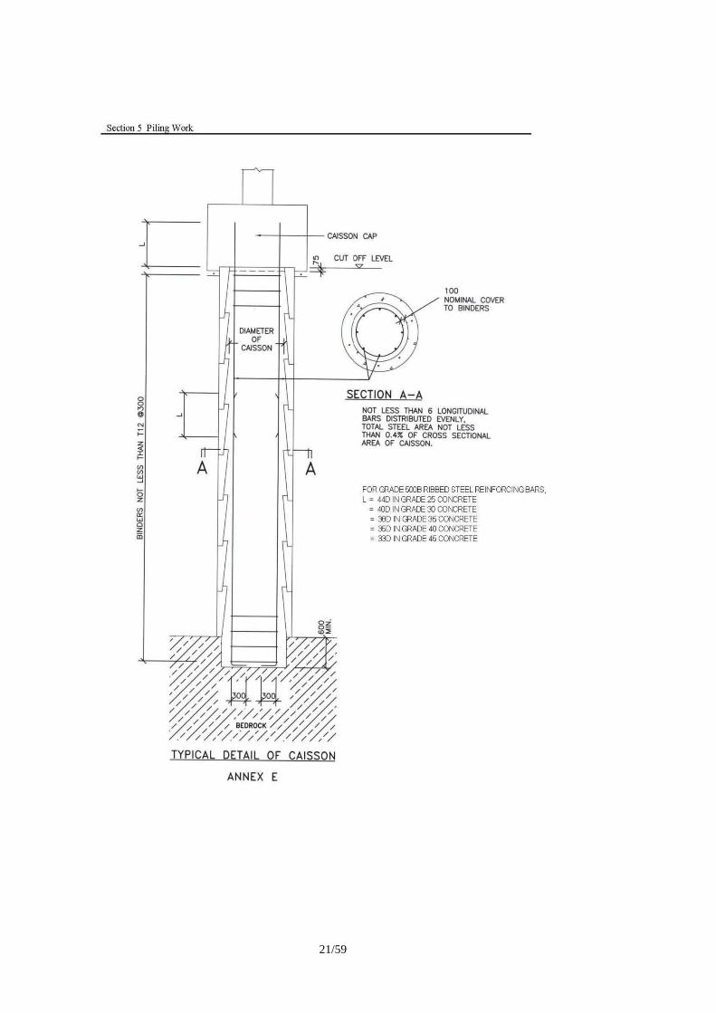
(g) Hand-dug caissons.

11/59
(h) Mini piles.
(i) Rock-socketed Steel H-piles.
(j) Barrette piles.
(k) Any other piling systems approved by the Development
Bureau.
(iii) Support all loadings as specified with piles. Unless otherwise stated,
all loads are acting at the geometric centres of columns and walls.
(iv) In addition to the loads given in the loading schedule, the weight of
pile caps or backfill over the pile caps and the imposed load over the
plan area of the pile caps, which shall be taken as 7.5 kN/m2 unless
specified otherwise, shall be included in the pile loading.
(v) Design piles for the most critical loading generally produced from the
following combinations:
(a) Dead load + imposed load + soil and water load.
(b) Dead load + imposed load + soil and water load + wind load.
NOTE: The theoretical safe loading capacity of piles in this
case may be increased to 1.25 times the appropriate values as
given in Clause 5.04.
(c) Minimum dead load + wind load + adverse soil + water load
(uplift) due to the highest anticipated groundwater table.
(vi) Piles shall not be positioned directly under any wall opening as
indicated on the drawing.
(vii) No piles or portions of pile caps outside the Site boundary shall be
permitted.
(viii) The use of tension piles shall not be permitted unless otherwise
stated.
(ix) Carry out piling work in accordance with Code of Practice for
Foundations published by Buildings Department.
(x) The piling work shall be executed by a Contractor on the List of
Approved Suppliers of Materials and Specialist Contractors for
Public Works - Land Piling.
(xi) The following works specified in the Contract shall be carried out by
an independent Ground Investigation Contractor from Group I or
Group II of the List of Approved Suppliers of Materials and
Specialist Contractors for Public Works – Ground Investigation Field
Work Category:
(a) site borings to pre-determine the piles founding levels in
accordance with Clause 5.19;
(b) pre-drilling for determination of pile length or to establish
bedrock level;

12/59
(c) core drilling;
(d) proof drilling;
(e) other works as instructed by the SO.
Percussion
piles
5.14 (i) Assess the safe loading capacity of the pile according to an approved
dynamic formula, e.g. Hiley Formula. For the purpose of design
calculation, the design factor of safety shall not be less than two.
(ii) The design final penetration shall generally not be taken as less than
2.5 mm per blow. The set penetration of at least 10 blows shall be
recorded on the Site during set. Where it can be demonstrated by
PDA analysis that the driving stress at final set is greater than 0.6 fy
for steel H-piles, the design final penetration may be taken as not less
than 1.0 mm per blow. The pile shall not be considered to have
attained the theoretical safe loading capacity should the penetration
of any blow recorded be in excess of the design final penetration.
(iii) If the Hiley Formula is used to calculate the loading capacity of a
pile, the temporary compression of the pile and hammer cushions
(Cc) shall be taken as not less than 7.5 mm when the thickness of the
hard wood packings at the pile head is 50 mm or less and the plastic
hammer cushion is 200 mm thick or less (refer to Clause 5.18 for
steel ‘H’ pile).
(iv) The efficiency of the hammer (Eh) and the coefficient of restitution of
the hammer cushion (e) shall be determined from/verified by
carrying out Dynamic Pile Test (PDA) and CAPWAP analysis on
trial piles (at least 5 piles for each hammer – pile size – drop height
combination). For steel H-piles, the measured driving stress of all
trial piles in PDA tests shall be greater than 0.6fy (where fy is the
minimum yield stress of the steel H-piles) as demonstrated with PDA
tests, and the 90% CAPWAP capacity of each trial pile shall not be
less than twice the theoretical safe loading capacity of the pile. The
combination of Eh and e shall be so chosen such that when these
values are substituted into the Hiley Formula, the average of the
predicted bearing capacity of the trial piles is not higher than 90% of
the average CAPWAP capacity. If the measured driving stress at
final set or 90% CAPWAP capacity requirements of each pile are not
satisfied, the theoretical safe load capacity of the piles shall be
reduced and submitted for SO’s approval.
(v) If reasonable values of design final set (not less than 2.5 mm or 1.0
mm per blow as the case may be) cannot be obtained from the Hiley
Formula with Eh and e so chosen and subject to the approval of the
SO, all the piles falling into this category shall be subject to Dynamic
Pile Test (PDA) and the theoretical safe loading capacity of the piles
shall be assessed by CAPWAP analysis. For steel H-piles, the
measured driving stress of the piles in PDA tests shall be greater than
0.6fy as demonstrated with PDA tests. The pile shall not be
considered to have attained the theoretical safe loading capacity
should the 90% CAPWAP capacity is less than twice the theoretical
safe loading capacity. In addition to the loading test requirements
in GS Clause 5.28, the SO shall select 1% of nos. of piles (minimum
one number) for each batch of piles proposed by the Contractor for
phased completion to be load tested for acceptance. All the time and

13/59
cost incurred from the PDA Tests, CAPWAP analyses and the
additional loading tests shall be borne by the Contractor. Employ an
Accredited Laboratory to carry out and interpret the PDA Tests,
CAPWAP analyses and the additional loading tests. The Accredited
Laboratory shall submit HOKLAS endorsed test reports directly to
the SO in sealed envelopes within 14 days of the completion of the
testing.
(vi) Drop hammer shall not be used for final set measurement. All final
sets shall be taken with the hydraulic hammer.
(vii) Driving of the last segment of pile shall normally be in one operation
and final set taken accordingly. If, for some reasons, this cannot be
done, the rate of penetration of the pile shall be recorded before
stopping. When pile driving is resumed, it shall be driven to attain at
least the previous rate of penetration before final set is taken.
(viii) If the protruding length of the pile above ground is more than 3m
during the final set measurement, the temporary compression of pile
above ground level (Cp+Cq) in the approved final set table shall be
increased by 1mm per each metre increase beyond 3m. However, in
all cases, the length of the protruding part of the pile above ground
level shall not exceed 6m during the measurement of final set.
(ix) The piles selected for PDA tests shall be tested under the same
driving conditions as in the final set measurement, i.e. same hammer,
same hammer drop height and total length of pile not less than that at
final set measurement. The set penetration of at least 10 blows shall
be recorded during the PDA tests. If the measured final set values of
the piles during the PDA tests are more than that during the final set
measurement, the theoretical safe loading capacity of these piles shall
be assessed by CAPWAP analysis. All the time and cost incurred
from CAPWAP analysis shall be borne by the Contractor.
Steel 'H' piles 5.18 (i) Steel sections must comply with the requirement of BS EN 10025
Grade S275, S355JR or S450J0.
(ii) Use steel sections with flange and web thicknesses not less than 20
mm.
(iii) For every one hundred segments or part thereof of each section of
same thickness from the same cast, one segment shall be selected at
random on site by the SO for testing. Provide two test specimens
taken at both ends of each of the chosen segment. For the purpose
of this clause, “same thickness” means similar sections with a
variation in thickness not exceeding + 5 mm, and “segment” means
every length of pile as rolled.
Prepare the test specimens to BS EN 10002-1 as directed and
appropriately mark and deliver them to the Public Works
Laboratories (PWL), as directed by the SO.
(iv) The energy of the hammer should be so chosen such that the pile will
not be damaged during driving. As a minimum requirement, the
Contractor shall demonstrate with PDA analysis that driving stresses
would not exceed 0.9 fy.
14/59
(v) Carry out splicing to increase the length of steel ”H” piles in
accordance with the details shown at Annex “B”. Unless agreed by
the SO, the minimum length of each steel H-pile section shall be 10m
except the uppermost section. Construct joints to maintain the true
alignment of the pile section. Welds shall be subject to the following
examination:
a) All welds shall be visually inspected to BS EN 970.
b) 10% of the welded joints shall be subject to ultrasonic
examination to BS EN 1714 Level B and magnetic particle
inspection to BS EN 1290.
There is no limit on hold time for the examination, except that the
initial 2 butt welded joints shall be examined by non-destructive tests
after 40 hours. Joints to be tested shall be selected by the SO. The
standard of acceptance for welds shall be in accordance with Table
14.3b in the Code of Practice for the Structural Use of Steel issued by
the Buildings Department.
Employ an Accredited Laboratory to carry out and interpret the
inspection and testing of welds, and provide any necessary labour
and attendance. The Accredited Laboratory shall submit test reports
directly to the SO in sealed envelopes within 3 days of the
completion of the testing. Tests revealing discontinuity shall be
reported separately from the subsequent repair and re-test.
(vi) Provide capping plates and dowel bars in accordance with the details
shown at Annex "C".
(vii) Pile of same size but of different grades shall not be used in the same
site.
(viii) If Hiley Formula is used to calculate the loading capacity of
steel ”H” pile, the temporary compression of the hammer cushion
( Cc) shall be taken as not less than 5 mm when plastic cushion of
200 mm thickness or less is used.
Large diameter
bored piles
5.19 (i) Large diameter bored piles are those of a diameter exceeding
750 mm formed by boring, chiselling or grabbing, plus filling with
concrete.
Provide reinforcement and adequate ties in accordance with details
shown at Annex "D".
(ii) Site borings to pre-determine the level of oversite bedrock shall be
carried out by an independent Ground Investigation Contractor from
Group I and Group II of the List of Approved Suppliers of Materials
and Specialist Contractors for Public Works – Ground Investigation
Field Work Category. One drill hole shall be sunk at each bored pile
position, whereas 2 drill holes are required for pile diameter
exceeding 2500mm. For this purpose, at least 5 m of continuous rock
core samples of N size (61 mm diameter) shall be taken for
inspection. Two copies of the drill hole logs shall be submitted
directly to the SO by the Ground Investigation Contractor.

15/59
(iii) Found pile on bedrock with a minimum embedment depth of 600
mm.
(iv) Bedrock is defined as rock mass of at least 5 m thick and being
Grade III/IV or better rock (as defined in GEOGUIDE 3, “Guide to
Rock and Soil Descriptions” prepared by Geotechnical Engineering
Office and published by GIS, Hong Kong).
For design purposes, the maximum bearing pressure of piles on
bedrock shall not exceed the following:
(a) 3 MPa for Grade III/ IV or better rock with total core
recovery greater than 75%
(b) 5 MPa for Grade III or better rock with total core recovery
greater than 85%
(c) 7.5 MPa for Grade II or better rock with total core recovery
greater than 95%
(v) Do not use piles with enlarged bases unless specified otherwise.
Where so permitted, the size of the enlarged base shall not exceed
1.5 times the shaft diameter with a gradient not exceeding 30
degree from vertical, and the enlarged base shall only be formed by
under-reaming with reverse circulation drill. The relevant
technique shall have been approved by the Development Bureau.
(vi) The requirements of Clause 5.17 (ii) apply equally to large
diameter bored piles.
(vii) Where the water level is higher than the bedrock level, carry out
concreting with a tremie pipe. Clean the pile base by air lift
before commencing concreting. Ensure the tremie pipe always
penetrates well below the top level of the concrete being poured.
(viii) Supply concrete in sufficient quantities to ensure that concreting of
each pile proceeds without interruption. The concrete shall have a
minimum cement content of 400 kg/m3 and a minimum slump of
150 mm.
(ix) Where the water level is higher than the bedrock level, the concrete
used shall have grade strength 25% higher than the design grade
strength.
(x) Where a pile is founded on a stratum which deviates from the
predicted depth by more than 4 m, carry out additional borings to
satisfy the SO that the pile is acceptable.
(xi) When defects such as voids, unbound sediment or segregation of
concrete are observed at the base of the pile, the Contractor shall
carry out remedial works to rectify such defects.
The Contractor shall first submit a method statement for approval.
Remedial works shall, inter alia, consist of further drilling to
determine the extent of the defects, cleaning by high pressure
jetting and subsequent pressure grouting. After completion, the
Contractor shall carry out verification coring to prove all defects
are properly filled with grout.

16/59
(xii) Where steep bedrock profile is identified, the founding levels of
adjacent piles shall not differ by more than the clear distance
between the pile bases unless the stability of rock under the piles
are checked by recognized engineering principles, taking into
account the existence of any adverse joints.
(xiii) For large diameter bored piles with diameters greater than 2000 mm,
reversed circulation drill (RCD) must be used to set the pile shaft in
rock and smooth out the rock surface. Should a similar machine
and equipment that achieves equivalent results and of equal
performance to that of the RCD be proposed, the contractor shall
demonstrate to the satisfaction of the SO before submitting for
approval.
Pile caps tie beams
and
5.25 (i) Unless otherwise specified, pile caps are part of the Works.
dowel bars (ii) (a) All pile caps and strap beams shall be designed by the
Contractor to Code of Practice for Structural Use of
Concrete, for the worst combination of load cases. The design
shall be certified by a Registered Structural Engineer.
Where specified, design tie beams to tie all columns in both
directions to take care of moments due to eccentricities
between load centre and centroid of pile or pile group
underneath. The eccentricities shall not be taken as less than
75 mm in any case.
(b) All concrete works for pile caps and strap beams shall be to
Section 6 of General Specification. Structural concrete shall
come from a supplier registered under the Quality Scheme for
the production and supply of concrete.
(c) PFA or GGBS concrete shall be used in all pile caps and
substructure construction where the concrete structural
elements bear a least dimension over 750 mm. The proportion
of PFA or GGBS of the total cementitious content in such
concrete shall be in accordance with Clause 6.30.
(d) A 50 mm blinding layer of grade 10/20 concrete shall be laid
prior to casting of pile caps and strap beams.
(e) Steel bars shall be plain steel reinforcing bars (denoted by R),
Grade 500B or 500C ribbed steel reinforcing bars (denoted by
T) to Hong Kong SAR Construction Standard CS 2. All
reinforcement shall be cut or bent to comply with BS 8666
unless otherwise specified.
(f) Cover to all bars including links and stirrups shall be 50 mm.
(g) If large concrete rafts are to be constructed:
(i) Allow sufficient chairs to support top reinforcement in
rafts.
(ii) The positions and method of forming construction joints
including sample treatment are to be submitted for
approval prior to work on site.

17/59
(iii) For concrete in large pile caps and piled rafts, measures
should be taken in temperature curing to minimize
temperature differential occurring in the concrete
sections. The side formwork shall not be removed during
the curing and as soon as the concrete is cast and
bleeding water disappears, the surface shall be cured for
a minimum of 4 days by either:
Covering the concrete with a layer of fine aggregate,
minimum 25 mm thick, and keep it constantly wet, or
Covering the surface with one layer of 50 mm thick
polystyrene boards secured with canvas on top.
(h) Where specified in the Contract, the Particular
Specification for Reinforced Massive Concrete
Structures shall apply.
(iii) Provide dowel bars as specified.
(iv) Thoroughly wire brush the dowel bars to remove all rust, scale,
adhered mud and the like, and prepare and apply a thick protective
coat of approved cement grout on all exposed areas of the dowel bars.
Non-
destructive
integrity testing
Preparation for
piles for
Sonic
Logging
5.32
5.35
Non-destructive integrity tests shall be carried out by a Testing Firm
appointed by the Employer. The Contractor shall, in addition to those items
listed in Clause 1.42, provide attendance and other preparatory works as
required.
The Contractor shall notify the SO 5 working days in advance for carrying
out the non-destructive integrity tests of piles on site.
Prepare piles for Sonic Logging
(i) Place in all large diameter bored piles, barrettes and diaphragm wall
panels, tubes of mild steel not less than 42 mm internal diameter
which shall be regular and free from defects, so as to permit the free
and unobstructed passage of the testing probes. Tubes shall be
watertight, free from corrosion with clean internal and external faces.
(ii) The tubes shall be fitted with a screw-on steel watertight shoe and
shall be securely fixed to the interior of the reinforcement cage or
fixed by other methods approved by the SO. The tubes shall be
parallel to each other and to the axis of the pile. Where sections of
tubing are required to be spliced, joints shall be made watertight.
(iii) The tubes shall be plugged or capped before concreting. The tubes
shall extend the full depth of the pile, barrette or diaphragm wall
panel, and stop at about 300 mm above the top of the concrete cast.
(iv) Install tubes in the number tabulated below and at spaces as directed
by the SO:
(a) Large diameter - 3 No./pile
bored piles, 700 -
900 mm diameter

18/59
Toe Coring
5.35.1
(b) Large diameter - 4 No./pile
bored piles,
exceeding 900 mm diameter
(c) Barrettes up to - 4 No./barrette
3.0 m long
(d) Barrettes over 3.0 m - Sets of 2 No. at 3.0 m
long and diaphragm centres/barrette or
wall panels diaphragm wall panel
(v) Before testing, fill up the tube with water to provide the necessary
acoustic coupling and refill with water prior to testing as necessary.
A plan shall be provided to the Testing Firm showing the layout and
the constructed length of the structural elements to be tested.
(vi) All tubes shall be cut off flush with the concrete and filled up by
pressure grouting with cement and sand (l:3) grout at completion of
all testing. All tubes shall be cut off flush with the concrete and filled up by pressure grouting with cement and sand (l:3) grout at completion of all testing.
(vii) Notwithstanding Clause 5.35 (i), for barrettes and large diameter
bored piles with diameter up to 2500 mm, one of the mild steel tubes
shall be replaced with a larger tube of 100 to 150 mm internal
diameter. For large diameter bored piles exceeding 2500 mm
diameter, two numbers of the mild steel tubes shall be replaced with a
larger tube of 100 to 150 mm internal diameter. Size of tube shall be
big enough to obtain a core of N size. The bottom of the larger steel
tube should be fitted with a mild steel cap, at about 700 mm above
the founding level of the pile.
Toe coring to obtain a core of N size to examine the interface between pile
and bedrock without coring through the entire length of pile shall be carried
out. One number of toe coring shall be carried out for each barrette and large
diameter bored pile with diameter up to 2500 mm and two numbers of toe
coring shall be carried out for each large diameter bored pile with diameter
exceeding 2500 mm. The toe coring length shall be more than 1400 mm of
which at least 700 mm shall be into bedrock

19/59

20/59
21/59

22/59
Amendments to Section 6
Steel
reinforcement
6.14 Steel reinforcement shall be plain steel reinforcing bars or ribbed steel
reinforcing bars to CS2 or steel fabric to BS 4483. Cold reduced steel
wire used for the manufacture of steel fabric shall be to BS 4482.
Test specimens
6.17 (i) Provide and cut test specimens from each batch of steel
reinforcement as directed by the SO. All test specimens shall be
appropriately marked and delivered to the Public Works
Laboratories (PWL) for testing. No claim in respect of steel
suffering from damage or rod lengths being reduced due to the
taking of testing specimens will be entertained.
(ii) Alternatively the Contractor may deliver test specimens to the
independent laboratories approved by the SO.
(iii) Test certificates shall be sent to the SO directly from these
independent laboratories.
(iv) Allow sufficient time for the testing of specimens. Do not use steel
reinforcement until the relevant test specimens have successfully
passed all tests. Remove unsatisfactory material off the Site when
instructed by the SO.
(v) For steel reinforcing bars, determination of mass per metre, tensile
test, rebend test, chemical analysis and test on bond property based
on surface geometry shall be carried out on test specimens for each
batch of steel reinforcing bars delivered to site in accordance with
CS2.
(vi) For fabric reinforcement, provide samples from each batch as
follows:
Sampling rate of fabric reinforcement
Size of batch No. of samples per batch
0 – 50 tonnes 1
Each additional 50 tonnes or part of
50 tonnes
1
(vii) Each sample shall comprise three 1.2 m long x 1.2 m wide test
specimens taken from different sheets in the batch. Each test
specimen shall contain at least three wires in each direction.
(viii) Each sample of fabric reinforcement shall be tested to determine the
yield stress, tensile strength, elongation, weld shear strength, rebend
performance, unit mass and pitch dimension.
(ix) The method of testing shall be in accordance with the following:
Cold reduced steel wire : BS 4482

23/59
Steel fabric : BS 4483
(x) The number of tests on each sample of fabric reinforcement shall be
as follows:
Description
Type and number of tests
Tensile Rebend Unit
Mass
Weld
Shear
Stress
Pitch
Dimension
Steel fabric
- fabric sheet - - 3 1 -
- longitudinal
wire
3 1 - - 1
- transverse
wire
3 1 - - 1
(xi) A batch of fabric reinforcement is considered as not complying with
the specified requirements for characteristic strength if the yield
stress in any tensile test carried out on any sample taken from the
batch is less than 93% of the specified characteristic strength. The
non-complying batch of fabric reinforcement shall be removed from
the Site.
(xii) If the yield stress of fabric reinforcement in any tensile test is less
than the specified characteristic strength but equal to or greater than
93% of the specified characteristic strength, additional samples
shall be provided from the same batch and additional tests for yield
stress shall be carried out. The number of additional samples shall
be as stated in Clause 6.17(vi).
(xiii) If the result of any test for yield stress, tensile strength, elongation,
weld shear strength, rebend, unit mass or pitch dimension does not
comply with the specified requirements for the property, additional
samples shall be provided from the same batch and additional tests
for the property shall be carried out. The number of additional
samples shall be as stated in Clause 6.17(vi).
(xiv) Each additional sample shall comprise six 1.2 m long x 1.2 m wide
test specimens taken from different sheets in the batch. Each test
specimen shall contain at least three wires in each direction. The
number of tests shall be as follows:

24/59
Description
Type and number of tests
Tensile Rebend Unit
Mass
Weld
Shear
Stress
Pitch
Dimension
Steel fabric
- fabric sheet - - 6 2 -
- longitudinal
wire
6 2 - - 2
- transverse
wire
6 2 - - 2
(xv) The batch of fabric reinforcement is considered as not complying
with the specified requirements for any particular property if the
result of any additional test does not comply with the specified
requirements for that property.
Aggregates 6.33 Aggregates shall be obtained from a source approved by the SO.
Aggregates from marine source and all-in aggregates shall not be used.
Coarse aggregate shall consist of clean, hard and durable crushed rock
complying with CS3.
Fine aggregate shall consist of clean, hard and durable crushed rock
complying with CS3. Natural sand shall not be used in production of
concrete unless otherwise agreed by the SO.
The flakiness index when determined to CS3 shall not exceed 40 for
aggregate of 40 mm size or larger, or 35 for sizes of 10 to 28 mm.
The potential alkali-reactivity category of coarse aggregate and fine
aggregate shall be determined from the results of tests on potential
alkali-reactivity of aggregates using the test method given in CS1.
Aggregates in the “Reactive” category shall not be used unless with the
prior approval of the SO.
Unless otherwise specified in the Contract, Sub-section 4.2.1 of CS3 on
Los Angeles value shall not be required for aggregates.
Grading of
aggregate
6.34 The grading of the combined fine and coarse aggregates shall be such as to
produce a dense concrete of suitable workability, using the specified
proportions of cement and water.
Aggregates shall be subjected to sieve analysis to CS3. The SO may
require further analysis to be made if there is any alteration in the type of
aggregate.

25/59
Water 6.35 Water for concreting shall be clean and uncontaminated potable water from
Government main supply or any other approved source. If taken from a
source other than Government main supply, it shall be tested in accordance
with BS EN1008 when required by the SO.
Wash water from concrete mixer washing operations (recycled water) may
be used for mixing concrete of grade strength not exceeding 35 MPa
provided that :
(i) The density of the combined water comprising tap water and
recycled water does not exceed 1030 kg/m3.
(ii) The 28 days strength of test cubes with combined water shall not
fall below 90% of control test cubes made with tap water.
(iii) The chemical limits of the combined water shall not exceed those in
Table 6.15.
(iv) Tests shall be conducted in accordance with Table 6.15.
TABLE 6.15
Chemical Limits for Combined Water (Recycled water and tap water) for each batching plant
Description Limits Test method Test frequency
Physical test
(a) Density test for recycled water
(b) Initial setting time of cement with
recycled water (time of set,
deviation from control, h:min)
1030 kg/m3
From 1:00 earlier to
1:30 later
Note 1
BS EN 196-3
At least once per day
Once every 3 months for the first
year and thereafter at half-yearly
intervals
Chemical test for recycled water
(a) Chloride content (as C1‾):
- prestressed concrete
steam-cured structural concrete
- concrete with reinforcement or
other embedded metal
(b) Sulphate content (as SO4)
(c) Acid-soluble alkali content
500 ppm
1,000 ppm
3,000 ppm
600 ppm
APHA 4500-C1-B
APHA 4500-Cl-B
APHA 4500-SO42-C
BS EN 1008
For all tests:
(i) Once per week for the first 2
months
(ii) Once per month for the next
12 months thereafter
(iii) In case of a weekly or
monthly test indicates that the
limits are exceeded, the water
shall immediately be
suspended for use in concrete
mixing until two sets of
consecutive test results taken
from the same source are
satisfactory. In such case,
the testing frequency shall be
maintained at or reverted
back to once per week until
two sets of consecutive test
results are satisfactory.
(iv) The testing frequency shall
be subject to review after the
12-month period for the
monthly test.
Notes: 1. Test method to be proposed by the Contractor for the acceptance of the SO.
2. Accredited Laboratory for the relevant tests shall be used, if available, in which case results shall be
issued on HOKLAS endorsed test reports.
3. Where ppm means part per million by mass

26/59
Standard mixes 6.41 If it is not proposed to use designed mixes, the standard mix proportions
shown in Tables 6.6 and 6.7 shall be used.
Compliance testing shall be in accordance with Clauses 6.55, 6.56 and
6.57. Notwithstanding the provisions of these clauses the SO may reduce
the frequency of sampling and testing if he is satisfied with the Contractor's
quality control.
Admixtures may be used subject to the provisions of Clause 6.36.
TABLE 6.7 Percentage by mass of fine aggregate to total aggregate
for standard mix concrete
Grade
strength (MPa)
Grading of the
aggregate
Nominal
maximum aggregate size
(mm)
40
20
10
10
C, M or F
30 - 45
35 - 50
-
C
Percentage by mass
of fine
30 - 40
35 - 45
45 - 55
20 , 25 or 30
M
aggregate to total aggregate (%)
25 - 35
30 - 40
40 - 50
F
25 - 30
25 - 35
35 - 45
Note : Grading C, M and F refer to those given in CS3
20% recycled
coarse
aggregates
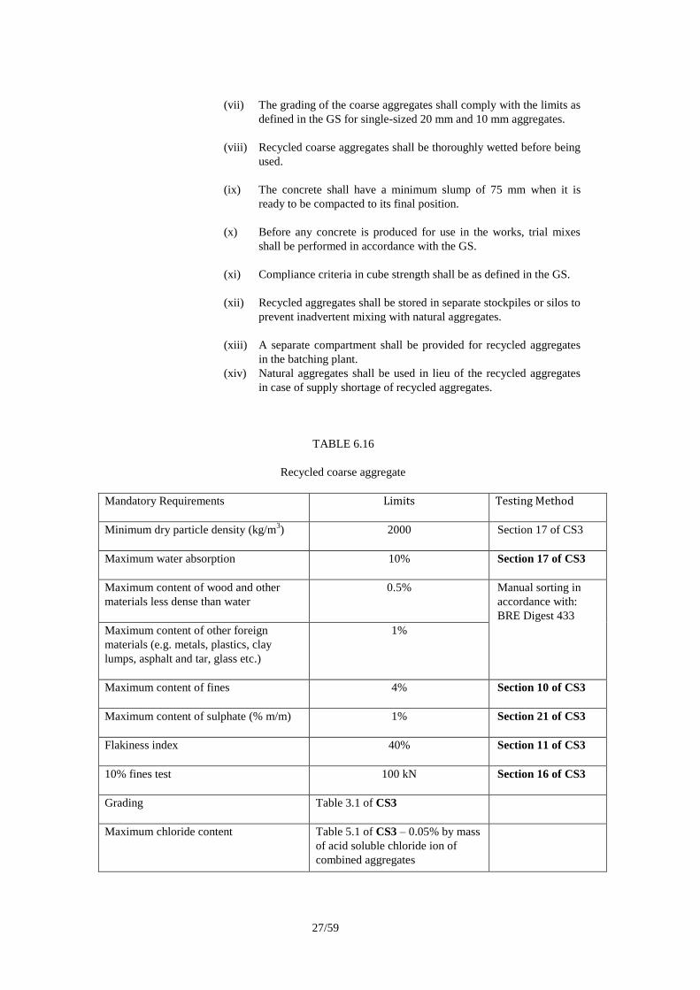
6.42.3 When specified, concrete with 20% recycled coarse aggregates shall be
used in designed mix concrete of 25 to 35 MPa grade strength except in
water retaining structures, subject to the following :
(i) Either Type CEM I of Portland cement to BS EN 197-1 or Type
CEM I Portland cement in combination with PFA can be used in
accordance with Clause 6.30.
(ii) Coarse aggregates shall consist of 80% natural rock aggregates as
defined in the GS and 20% recycled coarse aggregates.
(iii) Recycled coarse aggregates shall be produced by crushing old
concrete and shall meet the requirements in Table 6.16.
(iv) Tests on recycled aggregates from a particular source, with the
exception of Government sources, shall be carried out by the
aggregates producer at weekly intervals in compliance with Table
6.16.
(v) Fine aggregates shall be as defined in the GS.
(vi) Fine aggregates recycled from old concrete shall not be used.
27/59
(vii) The grading of the coarse aggregates shall comply with the limits as
defined in the GS for single-sized 20 mm and 10 mm aggregates.
(viii) Recycled coarse aggregates shall be thoroughly wetted before being
used.
(ix) The concrete shall have a minimum slump of 75 mm when it is
ready to be compacted to its final position.
(x) Before any concrete is produced for use in the works, trial mixes
shall be performed in accordance with the GS.
(xi) Compliance criteria in cube strength shall be as defined in the GS.
(xii) Recycled aggregates shall be stored in separate stockpiles or silos to
prevent inadvertent mixing with natural aggregates.
(xiii) A separate compartment shall be provided for recycled aggregates
in the batching plant.
(xiv) Natural aggregates shall be used in lieu of the recycled aggregates
in case of supply shortage of recycled aggregates.
TABLE 6.16
Recycled coarse aggregate
Mandatory Requirements
Limits Testing Method
Minimum dry particle density (kg/m3)
2000 Section 17 of CS3
Maximum water absorption
10% Section 17 of CS3
Maximum content of wood and other
materials less dense than water
0.5% Manual sorting in
accordance with:
BRE Digest 433
Maximum content of other foreign
materials (e.g. metals, plastics, clay
lumps, asphalt and tar, glass etc.)
1%
Maximum content of fines
4% Section 10 of CS3
Maximum content of sulphate (% m/m)
1% Section 21 of CS3
Flakiness index
40% Section 11 of CS3
10% fines test
100 kN Section 16 of CS3
Grading
Table 3.1 of CS3
Maximum chloride content Table 5.1 of CS3 – 0.05% by mass
of acid soluble chloride ion of
combined aggregates

28/59
Equivalent
sodium oxide
(Na2O) content
6.47.2 (i) The equivalent sodium oxide (Na2O) content of the concrete shall
be calculated from the following expression:
Equivalent Na2O = A + B + C
Where
A is the sum of the acid-soluble alkali content (expressed as
equivalent Na2O) of cement, admixtures and water;
B is equal to 1/6 the total alkali content of PFA (expressed as
equivalent Na2O) or 1/2 of the total alkali content of GGBS
(expressed as equivalent Na2O). If the proportion of PFA is less
than 20% or that of GGBS is less than 25% of the total
cementitious content, the value of B shall be equal to the total
alkali content of PFA or GGBS expressed as equivalent Na2O; and
C is equal to 0.76 times the chloride ion (Cl¯) of the aggregate.
(ii) The acid-soluble alkali content of the cement shall be determined in
accordance with BS EN 196-2 and shall be taken as the average of
the latest 25 daily determinations of equivalent sodium oxide plus
twice the standard deviation of the results.
(iii) The acid-soluble alkali content of admixtures shall be determined in
accordance with BS 1881-124.
(iv) The acid-soluble alkali content of water shall be determined in
accordance with BS EN 1008.
(v) The total alkali content of the PFA or GGBS shall be determined in
accordance with BS EN 196-2 and shall be taken as the average of
25 weekly determinations plus twice the standard deviation of the
results.
(vi) The chloride ion content of the coarse and fine aggregates shall be
measured in accordance with CS3.
Lintels 6.68 Cast lintels in concrete Grade 20/20 either precast or cast in-situ, and
construct as shown in Table 6.14.
Provide 25 mm minimum concrete cover between steel bar reinforcement
and soffit.
Allow bearing of 150 mm (minimum) at each end.

29/59
TABLE 6.14
Lintels
Clear span
(m)
Depth of lintel
(mm)
No. and diameter of steel
reinforcing bars per 105 mm
(or part) in width
0 - 1 150 One 12 mm
1 - 2 225 One 16 mm
2 - 3 300 One 20 mm
Amendments to Section 8
Aggregate
8.04 Provide coarse aggregate of 20 mm nominal maximum size with grading
within limits as defined in CS3 and fine aggregate with grading lying within
the limits of Grading C or M. Natural sand shall not be used in production
of concrete unless otherwise agreed by the SO.
Aggregates, if so instructed by the SO, shall be subjected to sieve analyses to CS3.
Amendments to Section 13
Timber for external use
13.01.1 (i) Species : Timber shall be either hardwood or softwood suitable for external use.
Approved softwood may be Radiata Pine, and Red or White Pine or those cited in Table NA.1 of BS EN 942. Approved temperate hardwoods may be Beech or Oak or those cited in Table NA.2 of BS EN 942. Submit the species to be used to the SO for approval.
(ii) Source of Supply : Obtain timber either softwood or hardwood
from a responsibly managed forest or plantation that is preferably Forest Stewardship Council (FSC) certified; where this is not available, ensure that the timber is at a minimum from a Known Licensed Source.
Submit FSC certificates and invoice copies that clearly show the FSC chain of custody number against the purchase product. Where FSC is not available, submit certificates, invoice copies and other paperwork from other systems that shows the product is either Known Licensed Source or Source in Progress to Creditable Certification.
(iii) Seasoning : Moisture content to be in accordance with
Clause 13.03. Maintain the specified moisture content of the

30/59
timber until preservative treatment described below is applied.
(iv) Preservative : Preservatives shall be environmentally riendly,
healthy and safe, acceptable preservatives include Alkaline copper quaternery (ACQ) preservatives to American Wood Protection Association (AWPA) Standards or other suitably approved preservatives. Chromate copper arsenic (CCA) is not allowed to be used subject to approval by the SO.
(v) Tropical hardwoods : Tropical hardwoods, which include species
such as Meranti, Iroko, Sapele, Angre,
Mahogony, Teak and Ramin, should not be
used unless they originate preferably from a
forest that is Forest Stewardship Council
(FSC) certified or where this is not available,
from a forest participating in a system
designed to progress that forest towards FSC
certification or equivalent authorized
certification.
Softwood 13.05 Softwood for carpentry to be Pine, Cedar, Spruce or China fir or other
species approved by the SO. All timber shall be appropriately stamped or
marked to identify origin and grade. All timber shall be kiln dried and
treated according to Clause 13.01.1 (iv), or as directed otherwise by the
SO.
All softwood and softwood products shall be from a verifiable sustainable
forest and shall be accredited with a certificate from the Forest Stewardship
Council (FSC) or other Approved Authority. While a certificate from FSC
is preferable, certificates, invoice copies and other paperwork from other
systems that shows the product is either Known Licensed Source or Source
in Progress to Creditable Certification are considered as acceptable
certificates from Approved Authority.
Wood block flooring
13.09 Wood block flooring shall be approved high density resin bonded
fibreboard flooring or other approved hardwood as specified. Resin shall
conform to Class E1 under BSEN 13986. Finished thickness shall be 20
mm (minimum). Blocks shall be 300 mm x 50 mm in size and colour
matched.
Plywood 13.12 Plywood shall be of the following grades, as specified:
(i) "Grade 1 veneer" - hardwood faced, as specified, for natural finish.
(ii) "Grade 2 veneer" - lauan faced for painting.
Generally the bonding adhesive between veneers shall be resin adhesive
classified as moisture and weather resistant (M.R.) in BS 1203. Adhesive
shall conform to the requirement in Clause 13.29.
Nominal standard thicknesses of plywood shall be 3, 4, 5, 6, 9, 12, 15, 18
and 25 mm.

31/59
Plywood containing hardwoods of unknown species or from unidentified
sources are expressly prohibited from use. Use only plywood and
plywood products made from softwoods or temperate hardwoods that
originate from the Forest Stewardship Council (FSC) certified forests or
other Approved Authority.
While a certificate from FSC is preferable, certificates, invoice copies and
other paperwork from other systems that shows the product is either
Known Licensed Source or Source in Progress to Creditable Certification
are considered as acceptable certificates from Approved Authority.
Acoustic tiles 13.22 Acoustic tiles shall be of an approved proprietary brand meeting the
requirements of BS EN 13964 manufactured from the following materials:
(i) Wood or other organic fibre insulating board to BS EN 622, 12 mm
(Minimum) thick for 300 mm x 300 mm tiles and 15 mm
(minimum) thick for 400 mm x 400 mm tiles.
(ii) Mineral fibre or wool insulating board 12 mm (minimum) thick for
300 mm x 300 mm tiles and 15 mm (minimum) thick for 400 mm x
400 mm tiles.
(iii) Approved multi-purpose, dimensionally stable building board 6 mm
(minimum) thick.
Tiles shall have a plain, perforated or fissured surface with a factory
applied decorative finish. The edges shall be square, bevelled, or bevelled
and grooved to suit the suspension system.
Provide a certificate from the manufacturer confirming that the tiles are
asbestos free.
Tiles shall be manufactured with low emission materials conforming to
European E1 emission standard.
Nails 13.24 Nails shall be steel nails to BS 1202:Pt. 1, with "bright" finish, unless
otherwise specified. The nail and its coating shall not contain Arsenic,
Cadmium, Copper, Lead or Mercury.
Nail lengths shall be not more than the total thickness of sections to be
joined less 5 mm, or not less than twice the thickness of section through
which nails are driven.
Where the thickness of the outer section through which nails are being
driven is less than half that of the section to which nailing is being done,
the depth of penetration of the nails into the latter shall be not less than 10
diameters of the nails being used.
Screws 13.25 Wood screws shall be brass, stainless steel, alloy or other non-corroding
metal to BS 1476 with countersunk heads, unless otherwise specified.
Steel screws shall only be used for temporary work. The proper dedicated
screws shall be used for all Particle-board fixing.
Screw lengths shall be not more than the total thickness of sections to be
joined, less 5 mm, or not less than one and a half times the thickness of
section through which screws are driven.

32/59
Where the thickness of the outer section being screwed is less than half that
of the section to which screwing is being done, the depth of penetration of
the screwing into the latter shall be not less than the thickness of the outer
section.
Screw cups shall be brass cups or stainless steel and to BS 1494.
Adhesive 13.29 Adhesive for wood shall be as follows:
(a) For internal use; synthetic resin adhesive classified as moisture
resistant and moderately weather-resistant (M.R.) in BS EN 204
and BS EN 301.
(b) For external use or internal use under very damp
conditions:synthetic resin adhesive classified as Type I in BS EN
301 and tested according to BS EN 302.
(c) Formaldehyde Emission shall be of Class E1 under BSEN 13986.
Adhesive for fixing laminated plastic sheet shall be synthetic resin adhesive
classified as type I in BS EN 301.
Where the temperature exceeds 25 degree C, a "warm-setting" grade of
adhesive shall be used.
The use of animal glues shall not be permitted.
Resin for MDF panels
13.29.1 All urea formaldehyde bonded MDF panels and MUF mouldings shall be
manufactured with low emission resins conforming to European E1 of
BSEN 13986 emission standard.
Wood preservative to external timber
13.30.1 Wood preservative to external timber shall be applied as follow:
(i) Preparation : Timber shall be free from dirt and
surface moisture.
(ii) Application of Preservative : Apply by pressure impregnation in
accordance with BS 8417.
Apply preservative in a manner that is
not hazardous to health. Adhere
strictly to the manufacturer’s
instructions.
(iii) Cutting and Machining : Whenever possible, all cutting,
planning, boring, drilling, notching or
any other machining or manual
operation shall be completed prior to
preservative treatment.
(iv) Incising : For certain timbers such as Douglas Fir
which are difficult to impregnate, make
20 mm deep incisions coverage of 650
per m2 in the direction of the grain all
in accordance with BS 144. This
method shall only be used on timber

33/59
sections exceeding 80 mm thickness.
(v) Creosote Application : For timber where impregnation is not
suitable and a paint finish is not
required, when approved apply 2 coats
of creosote in accordance with the
manufacturer’s instructions.
(vi) Guarantee : Obtain a guarantee of 30 years for
timber components against rot, insect
attack and fungal decay.
(vii) The product shall not contain any heavy metals or their compounds as
listed below:
- Arsenic
- Cadmium
- Copper
- Lead
- Mercury
Acoustic tiles 13.45 Fix acoustic tiles and the like to timber battens or direct to sub-base by
means of an approved adhesive used in accordance with the requirements
of Clause 13.29 and manufacturer's recommendations.
Wood block
flooring
13.50 Ensure that the base is clean and dry. Fix blocks to screed with an
approved cold bitumen/rubber emulsion adhesive as in Clause 13.29. Lay
to herringbone or basket pattern, as specified, with straight border two
blocks (minimum) wide.
Provide 5 mm expansion gap at perimeter of areas of wood block flooring,
and fill with one of the following:
(a) Cork strip
(b) Foam rubber strip
Sand surface of wood block flooring with an electric surfacing machine
using sequentially graded abrasive paper to obtain a smooth surface ready
to receive sealer or polish.
Machine shall be fitted with dust bag to control the release of dust.
Fire resisting
timber door
13.61 Fire resisting timber doors should be flush door as described above,
including frames, hinges door closers and any other hardware and shall
comply with BS 476: Part 20-23.
Proprietary fire doors should be tested in accordance with BS 476 and to
the approval of the SO. Test report shall be provided to indicate that the
material, product or construction is capable of resisting the action of fire
for the specified period. The test shall be carried out and the test report
shall be prepared by an Accredited Laboratory.

34/59
Amendments to Section 15
Materials for
grouting of base
plates and end
plates
15.15 Unless specified otherwise, grout around foundation bolts, under column
base plates and behind connection end plates shall be one of the following
types:
(a) Fluid cement mortar not leaner than 1:1 cement to fine aggregate by
volume and be mixed as thickly as possible consistent with fluidity.
The minimum amount of water is to be added to provide a viscosity
suitable for the voids to be filled without bleeding or segregation of the
fresh grout mix; or
(b) An approved proprietary non-shrink polymer modified cementitious or
resin based grout.
Grout shall have at least the same grade strength as the surrounding
concrete.
Testing of
sections and
plates
15.17 Provide one test specimen for every 40 tonnes or part thereof of each
section or plate of same thickness from the same cast. For the purpose of
this clause "same thickness" means similar sections with a variation in
thickness not exceeding + 5 mm. Test specimens shall be taken from
sections selected at random on Site by the SO.
Prepare the test specimens to BS EN 10002-1 as directed and appropriately
mark and deliver them to Public Works Laboratories, as directed by the
SO. Unless specified otherwise, the test specimens shall be subjected to
tensile test in accordance with BS EN 10002-1.
For proprietary structural steel products (e.g. playground equipment, lamp
posts), subject to the approval of the SO, manufacturer's certificates may be
accepted as proof of quality in lieu of sampling on site when all steel
sections are prefabricated by the manufacturer prior to shipment.
Through
thickness
properties
15.18 Ensure that where appropriate the steel material has adequate through
thickness properties to satisfy the design, the method of fabrication,
welding procedures and non-destructive inspection regime such that the
material at, or adjacent to, welds is free of laminations, centreline
segregation or other crack like indications on completion of welding.
Any material, which is specified or proposed by the Contractor to have
enhanced through thickness properties, shall comply with the requirements
of BS EN 10164. The Contractor shall, not less than three weeks prior to
ordering the steel, submit a report to the SO which documents the strategy
that will be adopted (in terms of material selection, weld procedure,
procedure trials, weld sequence, shrinkage control and inspection regime)
to ensure that the above criteria are satisfied.
If valid test reports issued by the manufacturer are not available, carry out
the following additional tests by Public Works Laboratories or an
Accredited Laboratory:
(a) Ultrasonic grading to BS EN 10160 Class S1 and BS EN 10306
Table 2 Class 2.3 for flat products and sections respectively; and
(b) Through-thickness tensile tests to BS EN 10164.

35/59
Installation and
testing of drill
anchor bolts
15.31 All drill anchor bolts shall be coordinated such that they do not clash with
any reinforcing steel bars of the concrete structure. Any deviation from
the specified positions shall be reported to the SO before installation.
Installation of drill anchor bolts shall strictly follow the manufacturer’s
specifications. Any installation procedures or details that deviate from the
manufacturer’s specifications shall be appended by a written statement
from the manufacturer to confirm strength of the anchors.
Where specified, carry out loading test of drill anchor bolts in accordance
with BS 5080: Pt. 1 and 2 at a sampling rate of at least 1% of the anchors
or 5 numbers, whichever is more, of each type and size of the anchors
installed. Each sample anchor shall be tested for tensile load by pull-out
test and/or shear load by shear load test, as appropriate, to not less than 1.5
times the recommended working load of the anchor as specified by the
manufacturer and with a minimum holding time of 60 minutes under
maximum test load. The sample anchor shall not show any signs of
separation, plastic deformation or deleterious effect, and shall have at least
80% recovery of the total deformation upon removal of the test load. If
the loading test of any sample anchor fails, the failure mode shall be
recorded and the cause shall be determined and reported to the SO. Propose
remedial measures, including justification calculations for any alternate
design and method statement, for agreement with the SO prior to carrying
out any remedial works. The sample anchor shall not be used for
permanent work unless agreed by the SO.
Employ an Accredited Laboratory to carry out the testing of drill anchor
bolts, and provide any necessary labour and attendance. The Accredited
Laboratory shall submit test reports directly to SO in sealed envelopes
within 3 days after the testing.
Method
statement
15.34 Prepare and submit details of the proposed method of erection for approval.
Details submitted shall include type of plant and equipment to be used and,
if necessary, drawings and calculations of any temporary work. Approval
shall not in any way relieve the Contractor of his responsibility for safe
erection of permanent work, or the safe erection and subsequent
dismantling of temporary work. Design, construct and dismantle
falsework to BS 5531 when specified.
Method statement for grouting under column base plates and connection
end plates shall be submitted for approval. Grouting trial shall be
conducted on site to verify the proposed method statement under site
conditions before approval.
Packings and
grouting
15.37 Bed column bases and connection end plates or grout anchor bolts only
after the steelwork has been plumbed, levelled, aligned, adequately braced.
Steel packings and wedges of sufficient strength and stiffness shall be used
to plumb and level columns before grouting, and shall be of sufficient size
to avoid local crushing of the concrete. They shall be placed so that they
do not prevent subsequent grouting to completely fill all spaces directly
under the column base plates or behind connection end plates. Grout shall
be applied under a suitable head and tamped or vibrated to remove air
pockets.
Where packings are to be left in position and subsequently grouted, they
are to be placed such that they will be totally embedded in the grout with

36/59
adequate cover.
Immediately before grouting, the space under column base plates or behind
connection end plates shall be clean and free of all extraneous matter.
Material for sealing the perimeters around the column base plates or
connection end plates for grouting shall be removed after grout has been
cured to expose the grout surface for inspection.
If grouting were carried out without approved method statement or without
agreement by the SO, demonstrate to the satisfaction of the SO that
approved grouting materials have been used and the grouted space is free
from void pocket.
Qualification
testing of
welding
procedure
15.47 Carry out qualification testing of approved pWPS by Welding Procedure
test to BS EN ISO 15607 and BS EN ISO 15614-1 strictly in accordance
with the approved pWPS and using representative samples of the materials.
The qualification testing including welding and testing shall be examined
by an Accredited Laboratory approved by the SO. Allow for the SO’s
inspection of the qualification testing.
Subject to the approval of the SO, qualification testing of pWPS need not
be carried out if the same procedures have been tested and approved by the
Accredited Laboratory.
Strictly follow the qualified WPS for the works. Carry out further
qualification tests if either the material or procedure changes.
Based on the qualified WPS, prepare appropriate work instructions for all
sizes of butt welds and fillet weld where leg length equals to or exceeds
10mm. Submit the work instructions for SO’s approval prior to the
commencement of welding. Work instructions shall include cross-reference
to the qualified WPS upon which they are based, and shall indicate clearly
all essential information including their acceptable range for the specific
weld size.
Welding
consumables
15.48 Consumables shall be to BS EN 499, BS EN 440, BS EN 756 or BS EN
758 as appropriate and strictly in accordance with the manufacturer's
recommendations.
Submit delivery notes of welding consumables to the SO. Maintain a log
book for welding consumables on site which shall contain the date, types
and quantities of welding consumables delivered on site, and the updated
balance. Submit daily record to the SO on the names of welders engaged,
welding joints under preparation, types and quantity of welding
consumables used.
Acceptance of
welds 15.58 Employ an Accredited Laboratory to carry out and interpret the inspection
and testing of welds, and provide any necessary labour and attendance.
Submit evidence proving that operators carrying out the inspection and
testing have been trained and assessed for competence in the inspection and
testing of welds. In addition, submit certificates of competence from a
recognised authority for operators carrying out ultrasonic examination.
Arrange for the Accredited Laboratory to submit a testing programme for
the approval of the SO. Any welds that shall be rendered inaccessible by
subsequent work shall be examined prior to the loss of access.
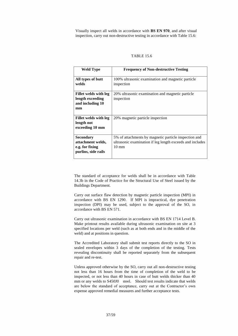
37/59
Visually inspect all welds in accordance with BS EN 970, and after visual
inspection, carry out non-destructive testing in accordance with Table 15.6:
TABLE 15.6
Weld Type
Frequency of Non-destructive Testing
All types of butt
welds
100% ultrasonic examination and magnetic particle
inspection
Fillet welds with leg
length exceeding
and including 10
mm
20% ultrasonic examination and magnetic particle
inspection
Fillet welds with leg
length not
exceeding 10 mm
20% magnetic particle inspection
Secondary
attachment welds,
e.g. for fixing
purlins, side rails
5% of attachments by magnetic particle inspection and
ultrasonic examination if leg length exceeds and includes
10 mm
The standard of acceptance for welds shall be in accordance with Table
14.3b in the Code of Practice for the Structural Use of Steel issued by the
Buildings Department.
Carry out surface flaw detection by magnetic particle inspection (MPI) in
accordance with BS EN 1290. If MPI is impractical, dye penetration
inspection (DPI) may be used, subject to the approval of the SO, in
accordance with BS EN 571.
Carry out ultrasonic examination in accordance with BS EN 1714 Level B.
Make printout results available during ultrasonic examination on site at 3
specified locations per weld (such as at both ends and in the middle of the
weld) and at positions in question.
The Accredited Laboratory shall submit test reports directly to the SO in
sealed envelopes within 3 days of the completion of the testing. Tests
revealing discontinuity shall be reported separately from the subsequent
repair and re-test.
Unless approved otherwise by the SO, carry out all non-destructive testing
not less than 16 hours from the time of completion of the weld to be
inspected, or not less than 40 hours in case of butt welds thicker than 40
mm or any welds to S450J0 steel. Should test results indicate that welds
are below the standard of acceptance, carry out at the Contractor’s own
expense approved remedial measures and further acceptance tests.

38/59
Generally 15.66 Fire protection system shall comply with the requirements of the Code of
Practice for Fire Safety in Buildings including its latest amendments and
revisions issued by the Buildings Department and shall provide the
structural steelworks with the required Fire Resistance Rating (FRR) as
specified in the Contract or as required by the Code of Practice for Fire
Safety in Buildings. In case that specified proprietary products are used,
they shall still comply with the requirements in Clauses 15.66 – 15.72.
Fire protection
system
15.67 When specified, provide fire protection to structural steel by one of the
following materials or system:
(i) Sprayed mineral coating to BS 8202: Pt. 1;
(ii) Intumescent coating system to BS 8202: Pt. 2; or
(iii) Proprietary fire protection board.
The fire protection system including its construction shall have been tested
and assessed to the requirements of BS 476: Pt. 20 and Pt. 21 as being
capable of resisting the action of fire for the specified periods. The tests and
assessment shall be carried out by an Accredited Laboratory, or one of the
assessing organizations listed in APP-118 issued by the Buildings
Department. The assessment report shall be within its validity period.
Details of application of the materials such as surface preparation,
application of primer, fixing details etc. shall be strictly in accordance with
the approved tests and assessment report; no deviation can be made except
for specific situations where some minor variations may be necessary.
Such variations must be tested or assessed by an Accredited Laboratory.
Submittals 15.68 The proposed fire protection system shall meet the design intent, the
required performance criteria and other requirements specified in the
Contract. The fire protection system must be approved by the SO before use.
Submit to the SO for approval all relevant information including but not be
limited to the following:
i. Product data: Data identifying performance characteristics and
properties of the fire protection material.
ii. Tests and assessment report prepared by an Accredited Laboratory as
specified in Clause 15.67 above, together with job references and
information of whether the product has been accepted by the Buildings
Department, Association for Specialist Fire Protection (ASFP),
Underwriters Laboratories Inc. or other international recognized
organizations.
iii. Details of the fire protection system including the thickness of
coating/board to be applied for each structural steel with calculation on
section factor ( Hp/A or A/V ) to substantiate that the required fire
rating can be achieved.
iv. Details of the surface preparation requirements and application
technique including fixing details of the material.
v. Certification from the fire protection coating manufacturer on the
compatibility of the coatings with the corrosion protection
coating/paints.

39/59
vi. Name of installation contractor qualified for the works and acceptable
to the fire protection coating/board manufacturer.
vii. Samples of the materials.
viii. Quality control and field test procedures.
ix. Installation, safety and protection procedures including those for repair
work.
Amendments to Section 17
Fire resisting shutters
17.42 The construction and installation of the fire resisting shutter shall comply
with the requirements of the Code of Practice for Fire Safety in
Buildings, Buildings Department. The activation devices shall be
constructed according to the requirements of Fire Services Department.
The operation of the fire shutter and the activation devices shall be tested
according to the requirements of the Codes of Practice for Minimum Fire
Services Installations and Equipment and Inspection, Testing and
Maintenance of Installations and Equipment, Fire Services Department and
the Building Services Branch Testing and Commissioning Procedure No. 3
for Fire Service Installation in Government Buildings, Architectural
Services Department.
The fire rated period of the fire resisting shutters shall satisfy the criterion
of integrity relating to the method of exposure on each side separately
when tested in accordance with BS 476:parts 20 to 24.
A test report prepared by an Accredited Laboratory or Building Authority
shall be provided to certify that the fire resisting shutter is capable of
resisting the action of fire for the specified period.
The fire resisting shutters shall be provided with smoke detector(s) and
manual control devise(s) on both side of the wall openings for automatic
and manual operation respectively. The detectors installed shall comply
with the requirements of the General Specification for Fire Service
Installation in Government Buildings of the Hong Kong Special
Administrative Region, Architectural Services Department.
Amendments to Section 18
Vinyl tiles 18.131 Unbacked flexible PVC (vinyl) tiles shall be to BS EN 649, size 225 x 225
or 300 x 300 and 2 mm thick.
Unbacked
flexible PVC
vinyl sheet
18.132 Unbacked flexible PVC (vinyl) sheet shall be to BS EN 649, 2.0 mm thick
to floors and 1.2 mm thick to walls.
Foam backed
vinyl sheet
18.133 Foam backed PVC (vinyl) sheet shall be to BS EN 651 and 3 mm thick
overall. The wearing layer shall be PVC (vinyl) sheet to BS EN 649 and
1.5 mm thick.

40/59
Amendments to Section 25
Topsoil 25.02 (a) Topsoil: evenly textured, fertile, dark brown or black, free draining,
sandy loam with the following properties:
(i) The top 300 mm fertile layer immediately below
undisturbed vegetation, and not derived from recent paddy
field cultivations;
(ii) Containing not less than 7.5% organic matter;
(iii) Having a pH value between 5.5 and 7.0;
(iv) Free from all kinds of pests, pernicious and/or perennial
weeds and roots, grass, clay lumps, non-soil material, brick,
cement, concrete and other building materials, foreign
matter and contamination;
(v) Maximum stone content % (m/m) as tested under BS 1377-2
Stone size in any direction: > 2 mm 30
> 20 mm 10
> 25 mm 0
If used in playing field or planting areas within and/or in
close proximity to recreational activities areas (such as
children playground and fitness station), the top 150mm
shall be free from stones exceeding 20 mm and not
sharp-edged in any direction.
(vi) Exchangeable sodium percentage (ESP) %: <15.
The source proposal of the Topsoil shall be submitted for the
approval by the SO at least 14 days before the relevant work starts.
Fabricated Soil
Mix
(b) Fabricated Soil Mix shall consist of friable, completely decomposed
granite (or volcanics) and manufactured soil conditioner in the
proportions of 3:1 by volume. The mix shall be mixed evenly and
shall be free from grass or weed growth, sticky clay, salt, chemical
contamination, and any other deleterious materials and stones as
Clause 25.02(a)(v) , and possess the following characteristics as
tested under BS 3882 and BS 1377-2
(i) pH value between 5.5 and 7.0;
(ii) Organic matter more than 10% (m/m);
(iii) Nitrogen content more than 0.2% (m/m);
(iv) Extractable phosphorous (P) content more than 25mg/l of
the mix;
(v) Extractable potassium (K) content more than 240 mg/l of
the mix;
(vi) Extractable magnesium (Mg) content more than 50mg/l of
the mix;

41/59
(vii) Soil texture content:
Sand (0.06 - 2.0 mm): at the range of 40% - 75%;
Silt (0.002 - 0.06 mm): at the range of < 40%;
Clay (less than 0.002 mm): at the range of < 20%
(viii) Maximum stone content % (m/m) as Clause 25.02(a)(v);
(ix) Exchangeable sodium percentage (ESP) %: <15.
Manufactured
soil conditioner
(c) Manufactured soil conditioner shall comprise properly composted
organic material with the following characteristics:
(i) Fine, free flowing consistency;
(ii) In stable condition;
(iii) Not capable of raising the temperature of the treated soil
more than 5ºC above the temperature of the untreated soil;
(iv) Free from impurities and not made with materials that are
known to contain pathogens or other toxic materials
injurious to plants, humans, or animals;
(v) Giving off neither toxic nor obnoxious fumes/odour;
(vi) With a pH value between 6.5 and 7.5;
(vii) With a moisture content when saturated between 30-50%
(moisture weight as a proportion of overall weight);
(viii) With an organic matter content of not less than 85% (dry
weight);
(ix) With a carbon nitrogen ratio between 20 and 30;
(x) No weed growth, other foreign matter or contamination.
Test for
manufactured
soil conditioner
(d) Certification: prior to first use and for every 300 m3 delivered to
Site, produce certificates of analysis of the soil conditioner from an
approved laboratory within 14 calendar days of taking the samples.
An approved laboratory shall mean one of the Employer’s
laboratories or an Accredited Laboratory. Tests shall be carried out
according to BS 3882 and BS 1377. Test report shall be in the
format as per the typical declaration of analysis under BS 3882.
Each certificate shall state the results of test for the following
properties stipulated for compliance in Clause 25.02(c):
(i) pH (H2O) value;
(ii) Organic matter content (dry weight);
(iii) Organic carbon content (using loss of ignition “Ashing”
method of testing);
(iv) Nitrogen content: (“Kjeldahl” Method);
(v) Carbon: nitrogen ratio;

42/59
(vi) Moisture content (calculated as the loss in weight between
the dry weight and the overall weight as a percentage of the
overall weight).
Sand (e) Sand shall be clean, sharp graded agricultural or horticultural sand 4
mm down to dust and not collected in brackish water marine
environment.
Lightweight Soil
Mix
(f) Lightweight Soil Mix shall consist of 2 parts of decomposed granite
as Clause 25.01(d), 1 part soil conditioner as Clause 25.02(c) and 1
part vermiculite pellets or volcanic pellets with a particle size of 5 –
10 mm. Maximum stone content % (m/m) shall comply with Clause
25.02(a)(v).
Alginate (g) Alginate shall be organic, derived from seaweed as soil improver, to
be incorporated into the top 300 mm of soil during cultivation,
when directed by the SO.
Soil stabilizer (h) Soil stabilizer shall be an approved proprietary type of binding
medium applied in an aqueous suspension by spraying onto the
surface of the soil to prevent short term erosion and to condition the
soil. The binding agent shall not be injurious to plant growth.
Stone chips (i) Stone chips shall be clean, sharp graded suitable for horticultural
use 4 – 2 mm, with no weed growth, free of other foreign matter or
contamination, and not collected in brackish water marine
environment.
Test for Topsoil
(j) Certification: prior to first use of any Topsoil from each approved
source and for every 300 m3 delivered to Site, produce certificates
of analysis of Topsoil from an approved laboratory within 14
calendar days of taking the samples. An approved laboratory shall
mean one of the Employer’s laboratories or an Accredited
Laboratory. Tests shall be carried out according to BS 3882 and BS
1377. Each certificate shall state the results of test for the properties
stipulated for compliance in Clauses 25.02(a).
Test for
Fabricated Soil
Mix
(k) Certification: after mixing operation but prior to first use in any
planting and/or grassing works and for every 300 m3 of the mix,
produce certificates of analysis of Fabricated Soil Mix from an
approved laboratory within 14 calendar days of taking the samples.
An approved laboratory shall mean one of the Employer’s
laboratories or an Accredited Laboratory. Tests shall be carried out
according to BS 3882 and BS 1377. Each certificate shall state the
results of test for the following properties stipulated for compliance
in Clause 25.02(b):
(i) pH (H2O) value;
(ii) Organic matter content (dry weight) expressed in %;
(iii) Organic carbon content (using loss of ignition “Ashing”
method of testing)
(iv) Nitrogen content: (“Kjeldahl” Method) expressed in %;
(v) Extractable phosphorous (P) content per litre of the sample;

43/59
(vi) Extractable potassium (K) content per litre of the sample;
(vii) Extractable magnesium (Mg) content per litre of the sample;
(viii) Soil texture content expressed in percentage of the following
categorization of soil particles sizes:
sand (0.06 - 2.0 mm), silt (0.002 - 0.06 mm) and clay (less
than 0.002 mm)
(ix) Stone content % (m/m) as tested under BS 1377-2;
(x) Soil salinity;
(xi) Moisture content (calculated as the loss in weight between
the dry weight and the overall weight as a percentage of the
overall weight);
(xii) Carbon: nitrogen ratio;
(xiii) Exchangeable sodium percentage (ESP) %.
Limestone 25.19 Limestone may be used to reduce the acidity of the soil. It shall be ground
limestone, containing a minimum of 90% calcium and magnesium
carbonates and capable of passing through a 10 mm mesh sieve. Prior to
use, take samples and produce a certificate of analysis of the limestone
from an approved laboratory within 14 calendar days of taking the sample.
An approved laboratory shall mean one of the Employer’s laboratories or
an Accredited Laboratory. Each certificate to state calcium and
magnesium carbonate content and the particle size.
Seed 25.40 An approved laboratory shall mean one of the Employer’s laboratories or
an Accredited Laboratory.
(a) All seed shall be true to species and laboratory tested. No seed shall
be used unless covered by an appropriately numbered seed analysis
report or certificate. The numbered reports or certificates shall
always refer to the number on the seed containers. The origin of
all seed and the name of the supplier shall be stated on the seed
containers.
The quality of grass seed shall be gauged by purity, germination
percentage and freedom from weeds. The total weed seed content
shall not exceed 0.5% by mass and the total content of other crop
seed shall not exceed 1% by mass.
Certificates of
seed
(b) Provide a certificate of testing for each species of seed from an
approved laboratory or supplier, stating:
(i) Grass species and variety using botanical names;
(ii) Date of testing (should not be more than 6 months before
the date of use of the seeds);
(iii) Test result on the percentage germination of pure seed in a
fixed time under standard laboratory conditions; and
(iv) Test result on the percentage composition by weight,
including details of purity.

44/59
Samples of
materials
(c) Samples of the following proposed materials shall be submitted to
the SO at the same time as particulars of the material are
submitted:
(i) Each seed mixture;
(ii) Turf (according to Clause 25.46(d) and 25.46(g)); and
(iii) Sprigs (according to Clause 25.46(g)).
Germination (d) The germination capacity of each constituent of a grass seed mix
over a seven-day test period shall be at least 80%.
Purity (e) The purity of each constituent of the grass seed mix shall be
greater than 90%. Total pernicious weed seed content shall be
less than 0.5% and total content of other crop seeds shall be less
than 1.0%.
Storage of grass
seed
(f) Store seed in sealed bags off the ground, in a clean, dry, well
ventilated place free from vermin. Prolonged storage shall be
carried out under controlled conditions of temperature and
humidity.
Pre-seeding
fertilizer
(g) Pre-seeding fertilizer shall be a quick release fertilizer.
Artificial plants 25.66 (a) Artificial plants shall be obtained from an approved supplier.
Samples of each plant for species and size shall be approved prior
to purchase from the supplier.
(b) Artificial plants shall have the following properties:
(i) Man-made, densely leaved with flowers and foliage of
colour-fast silk or polyester with realistic appearance in
terms of general form, colour, texture and habit resembling
the life-like version of the plant species;
(ii) All preserved or dried components of the artificial plants
shall be free form rotting, insect and/or fungus infestation; ;
(iii) Multi-stemmed when appropriate to the species;
(iv) With all leaves, flowers, stems, trunks, branches etc.
securely fixed;
(v) Set in appropriate size pots entirely filled with dark brown
coloured concrete or by an approved method without
leaving a protruding lip.
(vi) Leaf to be strongly bonded to plastic backing, single bond
between leaf and stem is not acceptable;
(vii) All silk sprays and bushes shall be treated with fire
retardant chemicals and accompanied by a test certificate
from an Accredited Laboratory;
(viii) No rough silk threads on the edge of leaves;

45/59
(ix) All silk sprays and bushes should be firmly secured into
styrofoam support base, covered with decorative Sphagnum
green moss, decorative stones/pebbles or other approved
materials; and
(x) Wire strengtheners in stem must be sufficiently strong to
support the bush in its natural shape.
(c) Submittals for SO’s approval prior to ordering:
(i) Detailed layout plans with sections, elevations to
demonstrate design proposal.
(ii) Color photographs and job reference shall be submitted for
each proposed plant.
(iii) Mock up of full size sample for each type of proposed silk
tree or preserved palms, and major group of silk bushes,
for approval.
(iv) Sample of all other materials such as container, decorative
moss / pebbles, etc. shall be submitted for approval.
(v) Proof or guarantees from manufacturer on fire retardant or
preservatives treatment, as detailed above.
Amendments to Section 26
Material 26.34 (a) Soil nail bars shall be of high yield deformed bars and comply with
CS2. All steel components for soil nails shall be galvanized to BS
EN ISO 1461.
(b) Steel reinforcement for soil nail heads shall be Grade 500B ribbed
steel reinforcing bars to CS2.
(c) Nuts shall be of Grade 4 steel and comply with BS 4190.
(d) Reinforcement connectors shall comply with Clause 6.24.
(e) Bearing plates shall be of Grade S275 steel plate and comply with
BS EN 10025. Steel plates for pull-out and performance tests
shall be square with length not less than 300mm and ratio of length
to thickness not larger than 10. Holes in steel plates for soil nail
heads shall be drilled perpendicular to the face of the steel plate and
centre of the hole shall be at a position of within 2mm from the
centroid of the plate. The clearance between the steel bar and the
hole of the steel plate shall not be more than 2mm.
(f) Concrete for soil nail heads shall be grade 30/20 or 30 MPa sprayed
concrete and shall comply with Clauses 26.47-57 and Clauses
26.12-28 respectively.
(g) Soil nails shall have non-corrodible centralizers capable of ensuring
an even annulus of grout around the steel bar. The nominal
diameter of the centralizers shall not differ from the specified
diameter of the drillhole by more than 10 mm. Wires and ties for
fixing and anchoring packers, centralizers and grout pipes etc. shall

46/59
be made of non-corrodible materials. Determine the spacing of the
centralizers and the suitability of the method of fixing the
centralizers, grout pipes and corrugated sheathing where required
by carrying out trials on site until no damage, deformation and
displacement of the centralizers, grout pipes and corrugated
sheathing are observed on completion of assembling all
components, during inserting and withdrawing the soil nails. Once
approval is given, no change to the type, method and arrangement
of fixing of the centralizers, grout pipe and corrugated sheathing
shall be made without the prior approval of the SO.
(h) For soil nails using threaded type reinforcement connectors but
without galvanized coating on either the threads inside the
connectors or the threads at the ends of reinforcement bars, use
heat-shrinkable sleeve of a proprietary type as approved by the SO
as an alternative to galvanization as a corrosion protection measure
to the connections. Clean thoroughly any rust on the threads of
reinforcement bars and connectors before being connected together.
(i) A typical layout and design of soil nails is as shown in Appendix 4.
Granular filter 26.60 (a) Granular filter shall consist of durable, inert, natural material free
from clay, organic material and other impurities. Design granular
filter materials in accordance with the design criteria stated in GEO
Publication 1/93 and current amendments.
(b) Submit the following particulars of the proposed materials and
methods of construction for granular filters to the SO:
(i) Whether granular filter material is to be supplied ready
mixed or is to be mixed on the Site,
(ii) Source of supply, including name of supplier of ready mixed
material,
(iii) Quantity of each constituent if the material is to be mixed on
the Site,
(iv) Constructional plant and methods of mixing for material
mixed on the Site,
(v) Method of storage and location of storage areas on the Site,
(vi) Methods of deposition and compaction of material,
(vii) Results of three tests for particle size distribution of the fill
material against which the granular filter is to be placed, and
(viii) Details of filter design including calculations and grading
envelopes.
(c) Submit the particulars to the SO for approval at least 14 days
before deposition of granular filter material starts.
(d) Submit samples to the SO for approval of the source and type of
each material at the same time as particulars of the material are
submitted.

47/59
(e) Do not handle or store granular filter material in a manner which
will result in mixing of the different types and sizes or in
segregation, contamination, deterioration or erosion of the material.
(f) Place stockpiles of granular filter material on well-drained,
prepared
areas, and separate them by dividing walls of sufficient height to
keep the different materials separate.
(g) Mix thoroughly granular filter material by the method approved by
the SO, and remix material which has been stockpiled before
deposition.
(h) Compact granular filter materials in accordance with the
requirements for rock fill materials as stated in Clause 3.20.
(i) Deposit granular filter material in a manner which will not result in
segregation or contamination of the material.
(j) Deposit granular filter material in such a manner that a continuous
free draining zone is formed. Clean and scarify the surface of
each layer before the next layer is deposited unless otherwise
permitted by the SO.
(k) A batch of granular filter material is any quantity of granular filter
material of the same type and grading delivered to the Site at any
one time
(l) (i) Provide one sample of granular filter material from each
500m3 or part thereof of the material delivered to the Site.
(ii) Unless otherwise permitted by the SO, provide one sample of
granular material from each 500m3 or part thereof of
granular filter material which has been deposited and
compacted.
(iii) The size of each sample taken as stated in Clause 26.60(l)(i)
shall be 10 kg. The method of sampling shall be in
accordance with CS3.
(iv) Samples taken as stated in Clause 26.60(l)(ii) shall consist of
material excavated from the compacted layer to form a flat
bottomed, steep sided hole of approximately 0.13 m2 to the
complete depth of the compacted layer. A template shall be
used to fix the edges of the hole if necessary. The sides and
bottom of the hole shall be at least 50mm from other types of
fill material.
(m) (i) Test each sample of granular filter material to determine the
particle size distribution.
(ii) The method of testing shall be in accordance with the wet
sieving method stated in Geospec 3, Test Method 8.2.
(n) (i) If the result of any test for particle size distribution on a
sample of granular filter material taken as stated in Clause
26.60(l)(i) does not comply with the specified requirements
for particle size distribution, provide additional samples

48/59
from the same batch and carry out additional tests for
particle size distribution.
(ii) The batch shall be considered as not complying with the
specified requirements for particle size distribution if the
result of any additional test for particle size distribution
does not comply with the specified requirements for particle
size distribution.
(iii) If the result of any test for particle size distribution on a
sample of granular filter material taken as stated in Clause
26.60(l)(ii) does not comply with the specified requirements
for particle size distribution, provide additional samples
from the same batch and carry out additional tests for
particle size distribution. The number of additional samples
shall be as stated in Clause 26.60(l)(ii).
(iv) The batch shall be considered as not complying with the
specified requirements for particle size distribution if the
result of any additional test for particle size distribution
does not comply with the specified requirements for particle
size distribution
(o) Typical details of filter blanket for fill slope are as shown in the
Standard Drawing in Appendix 7.

49/59

50/59

51/59

52/59

53/59

54/59

55/59

56/59

57/59

58/59

59/59
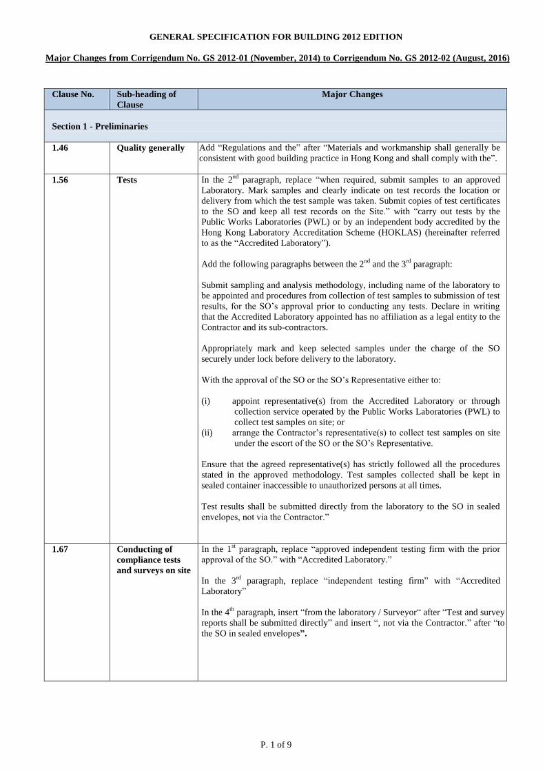
P. 1 of 9
GENERAL SPECIFICATION FOR BUILDING 2012 EDITION
Major Changes from Corrigendum No. GS 2012-01 (November, 2014) to Corrigendum No. GS 2012-02 (August, 2016)
Clause No.
Sub-heading of
Clause
Major Changes
Section 1 - Preliminaries
1.46 Quality generally Add “Regulations and the” after “Materials and workmanship shall generally be
consistent with good building practice in Hong Kong and shall comply with the”.
1.56
Tests In the 2nd
paragraph, replace “when required, submit samples to an approved
Laboratory. Mark samples and clearly indicate on test records the location or
delivery from which the test sample was taken. Submit copies of test certificates
to the SO and keep all test records on the Site.” with “carry out tests by the
Public Works Laboratories (PWL) or by an independent body accredited by the
Hong Kong Laboratory Accreditation Scheme (HOKLAS) (hereinafter referred
to as the “Accredited Laboratory”).
Add the following paragraphs between the 2nd
and the 3rd
paragraph:
Submit sampling and analysis methodology, including name of the laboratory to
be appointed and procedures from collection of test samples to submission of test
results, for the SO’s approval prior to conducting any tests. Declare in writing
that the Accredited Laboratory appointed has no affiliation as a legal entity to the
Contractor and its sub-contractors.
Appropriately mark and keep selected samples under the charge of the SO
securely under lock before delivery to the laboratory.
With the approval of the SO or the SO’s Representative either to:
(i) appoint representative(s) from the Accredited Laboratory or through
collection service operated by the Public Works Laboratories (PWL) to
collect test samples on site; or
(ii) arrange the Contractor’s representative(s) to collect test samples on site
under the escort of the SO or the SO’s Representative.
Ensure that the agreed representative(s) has strictly followed all the procedures
stated in the approved methodology. Test samples collected shall be kept in
sealed container inaccessible to unauthorized persons at all times.
Test results shall be submitted directly from the laboratory to the SO in sealed
envelopes, not via the Contractor.”
1.67
Conducting of
compliance tests
and surveys on site
In the 1st paragraph, replace “approved independent testing firm with the prior
approval of the SO.” with “Accredited Laboratory.”
In the 3rd
paragraph, replace “independent testing firm” with “Accredited
Laboratory”
In the 4th
paragraph, insert “from the laboratory / Surveyor“ after “Test and survey
reports shall be submitted directly” and insert “, not via the Contractor.” after “to
the SO in sealed envelopes”.

P. 2 of 9
Clause No.
Sub-heading of
Clause
Major Changes
Section 3 – Excavation and Earthwork
3.01 Definitions
Replace sub-clause (i)(b) “title” with “tile”.
Replace sub-clause (ii) “material” with “suitable material”, delete “be approved
and to”.
Add to end of sub-clause (iii) “any of”.
At the end of sub-clauses (iii)(a) & (iii)(b), replace “,” with “.”
At the end of sub-clauses (iii)(c), replace “, or” with “.”
Add to sub-clause (v)(a) “and durable rock of which the maximum size shall not
be greater than three times the minimum dimension of individual pieces and”
and replace “particle shall exceed 0.1m3” to “pieces shall exceed 400mm” and
delete “or the thickness of the filling whichever is the least”.
Replace sub-clause (v)(b) “"fill” with “filling”.
Replace sub-clause (vi) “Hardcore shall comprise the following material to pass
rings varying from 28 to 150mm (from 28 to 200mm for recycled rock fill), or
else, single sized hardcore may be used:” with “Hardcore shall comprise the
following with no material exceeding 150mm in size”.
Insert sub-clause (viii) “Fine filling material shall be suitable material capable of
passing through a 75mm BS sieve.”
Re-number sub-clause (viii) – (xiii) to (ix) – (xiv).
Replace sub-clause (ix) “general filling” with “suitable” and “material” with
“special filling material”.
Replace sub-clause (ix) (d) “weight” with “mass”.
3.04 Temporary works
for earthworks
Add “The Contractor shall provide details to SO to demonstrate that the design
of Temporary Works has been considered and incorporated measures, which
minimise excavation of materials.”
3.08 Generally
Delete sub-clause (i) “Carry out and” and replace “Constructional Plant” with
“Construction plant”.
3.16 Surface preparation
for filling material
Add “all soft spots, loose boulders, grass, top soil, bushes, trees, roots and other
vegetation or rubbish in” and delete “of all soft sports, loose boulders, grass top
soil bushes, trees, roots and other vegetation or rubbish” and replace “fill
material” with “filling material”.
3.17 Filling
Replace sub-clause (i) “filling including backfilling” with “filling material”.
Replace sub-clause (ii) “Constructional Plant” with “construction plant” and add
“filling material”.
Replace sub-clause (iv) “fill” with “filling”.
Delete sub-clause (v) “graded”.
3.19 Compaction by
performance
specification
Replace sub-clause (i) “fill” with “filling”.
Replace sub-clause (ii) “each class of” with “the”.
3.20 Compaction by
method
specification
Delete sub-clause 3.20 (i) “in accordance with Clause 3.23(v)”.
Replace sub-clause 3.20(ii) “fill” with “filling”.

P. 3 of 9
Clause No.
Sub-heading of
Clause
Major Changes
Replace sub-clause 3.20(ii) (a) “fill” with “filling” and “general fill” with “filling
material” and “graded” with “filling”.
Replace table 3.3 “fill” with “filling” and “150” with “250”.
3.21 Test for
determining the
degree of
compaction of
compacted fill
Delete “the personnel of” and “or if PWL not available by an approved
independent testing firm when the prior approval of the SO has been obtained,
using their own equipment and provide such labour and assistance as may be
required.”
3.23
Embankments Replace sub-clause 3.23 (v) “graded” with “filling”.
3.29 Deposition of soil-
cement fill
Replace sub-clause 3.29 (ii) “fill materials” with “filling materials”.
Section 5 – Piling Work
5.01 General
In sub-clause (v)(c), replace “2/3 Dead load + Wind load + water uplift” with
“Minimum dead load + wind load + adverse soil + water load (uplift) due to the
highest anticipated groundwater table.”
5.14 Percussion piles
In sub-clause (ii), replace “Where it is evident from ground investigation records
that piles are founded on rock, or it can be demonstrated with PDA analysis that
the driving stress at final set is greater than 0.65 fy for steel H-piles,” with
“Where it can be demonstrated by PDA analysis that the driving stress at final set
is greater than 0.6 fy for steel H-piles,”.
Sub-clauses (iv) and (v) general revised.
Sub-clauses (viii) and (ix) added.
5.18 Steel 'H' piles Add a new paragraph in sub-clause (v) as follows:-
“Employ an Accredited Laboratory to carry out and interpret the inspection and
testing of welds, and provide any necessary labour and attendance. The
Accredited Laboratory shall submit test reports directly to the SO in sealed
envelopes within 3 days of the completion of the testing. Tests revealing
discontinuity shall be reported separately from the subsequent repair and re-test.”
5.19 Large diameter
bored piles
In sub-clause (ii), replace “One drill hole shall be sunk at each bored pile
position.” with “One drill hole shall be sunk at each bored pile position, whereas
2 drill holes are required for pile diameter exceeding 2500mm.” and replace
“Two copies of the drill hole logs have to be submitted to the SO.” with “Two
copies of the drill hole logs shall be submitted directly to the SO by the Ground
Investigation Contractor.”
Sub-clause (xiii) added.
5.25 Pile caps tie beams
and dowel bars
Replace sub-clause (i) with “Unless otherwise specified, pile caps are part of the
Works.”.
In sub-clause (ii)(c), replace “PFA” with “PFA or GGBS” and replace the last
sentence “The PFA content must constitute between 25% and 35% of the total
cementitious content in such concrete.” with “The proportion of PFA or GGBS
of the total cementitious content in such concrete shall be in accordance with
Clause 6.30.”
In sub-clause (ii)(e), replace “Steel bars shall be hot rolled plain round bars
(denoted by R) or deformed high yield bars (denoted by T) to Hong Kong SAR
Construction Standard CS 2:1995.” with “Steel bars shall be plain steel
reinforcing bars (denoted by R), Grade 500B or 500C ribbed steel reinforcing
bars (denoted by T) to Hong Kong SAR Construction Standard CS 2.”

P. 4 of 9
Clause No.
Sub-heading of
Clause
Major Changes
5.32 Non-destructive integrity testing
Add a new paragraph as follows:-
“The Contractor shall notify the SO 5 working days in advance for carrying out
the non-destructive integrity tests of piles on site.”
5.35 Preparation for piles for Sonic Logging
In sub-clause (vii), move “Toe coring to obtain a core of N size to examine the
interface between pile and bedrock without coring through the entire length of
pile shall be carried out. One number of toe coring shall be carried out for each
barrette and large diameter bored pile with diameter up to 2500 mm and two
numbers of toe coring shall be carried out for each large diameter bored pile with
diameter exceeding 2500 mm. The toe coring length shall be more than 1400
mm of which at least 700 mm shall be into bedrock.” to a new sub-clause 5.35.1
with heading “Toe Coring”.
Annex C Capping Plates and Dowel Bars Details of Steel H Pile
Replace “5 nos. 25mm dia. hole for tack weld” with “5 nos. 25mm dia. hole for
plug weld”.
Replace “2 no. R20-U bar” with “2 no. T20-U bar”.
Replace “Tack Weld” with “Plug Weld”.
Annex D Reinforcement and Ties Details of Large diameter bored pile
Replace “For Grade 460 reinforcement deformed Type 2 bars” with “For Grade
500B ribbed steel reinforcing bars”.
Reinforcement lap lengths “L” for various concrete grades revised.
Annex E Typical Detail of Caisson
Replace “For Grade 460 reinforcement deformed Type 2 bars” with “For Grade
500B ribbed steel reinforcing bars”.
Reinforcement lap lengths “L” for various concrete grades revised.
Section 6 – Structural Concrete Works
6.14 Steel reinforcement Replace “Steel reinforcement shall be plain round steel or deformed high yield
steel bars to CS2…” with “Steel reinforcement shall be plain steel reinforcing
bars or ribbed steel reinforcing bars to CS2…”.
6.17 Test specimens Replace sub-clause (v) “For steel bars, tensile, bend and rebend tests shall be
carried out on test specimens as required by CS2” with “For steel reinforcing
bars, determination of mass per metre, tensile test, rebend test, chemical analysis
and test on bond property based on surface geometry shall be carried out on test
specimens for each batch of steel reinforcing bars delivered to site in accordance
with CS2”.
6.33 Aggregates Replace 2nd paragraph “Coarse aggregate for concrete shall consist of clean,
hard, durable crushed rock to BS 882. The grading shall lie within the limits
given for the appropriate nominal size in Table 6.3 unless otherwise agreed by
the SO” with “Coarse aggregate shall consist of clean, hard and durable crushed
rock complying with CS3”.
In 3rd
paragraph, replace “Fine aggregate shall consist of crushed rock as for
coarse aggregate or clean sand. The grading shall lie within the limits of one of
the grading C, M or F of Table 6.4, or for crushed stone fines only, the limits as
shown in Table 6.5” with “Fine aggregate shall consist of clean, hard and
durable crushed rock complying with CS3”.
In 4th
paragraph, replace “BS 812-105.1” with “CS3”.
Add a new paragraph as follows
“Unless otherwise specified in the Contract, Sub-section 4.2.1 of CS3 on Los
Angeles value shall not be required for aggregates”.
Tables 6.3, 6.4 and 6.5 are deleted.

P. 5 of 9
Clause No.
Sub-heading of
Clause
Major Changes
6.34 Grading of
aggregate
In 2nd
paragraph, replace “….BS 812-103.1, and the limits of acceptance are as
shown in Table 6.3, 6.4 and 6.5” with “CS3”.
Tables 6.3, 6.4 and 6.5 are deleted.
6.35 Water In Notes no. 2 of the Table 6.15, replace “Laboratories accredited by the Hong
Kong Laboratory Accreditation Scheme (HOKLAS)” with “Accredited
Laboratory”. 6.41 Standard mixes Table 6.7 is revised to delete “BS 882: Table 5” and “Table 6.5”.
Footnote of Table 6.7 is revised to “Grading C, M and F refer to those given in
CS3”.
6.47.2 Equivalent sodium
oxide (Na2O)
content
Replace “BS812-117” with “CS3” in Sub-clause (vi).
Table 6.16 of
6.42.3
20% recycled
coarse aggregates
Table 6.16 is revised to replace “BS 812” and “BS882” with “CS3” as follows:
BS 812: Part 2 to Section 17 of CS3
BS 812 103.1 to Section 10 of CS3
BS 812 118 to Section 21 of CS3
BS 812 105.1 to Section 11 of CS3
BS 812 111 to Section 26 of CS3
Table 3 of BS 882 to Table 3.1 of CS3
Table 7 of BS 882 to Table 5.1 of CS3
Maximum content of sand (<4 mm) (% m/m) is deleted
6.68 Lintels Table 6.14 is revised to replace “steel bars” with “steel reinforcing bars”.
Section 8 – Concrete for minor and Non-Structural Works
8.04 Aggregate In 1st paragraph, replace “….in the GS and fine aggregate with grading lying
within the limits of Grading C or M of Table 6.4 or for crushed stone fines in
accordance with Table 6.5” with “…. in CS3 and fine aggregate with grading
lying within the limits of Grading C or M”.
In last paragraph, replace “BS 812”-103.1 with “CS3”.
Section 13- Carpentry and Joinery
13.01.1 (iv) Preservative Delete “Clear colourless”, replace “to BS 4072 may” with “is not allowed to” and
delete “, provided that adequate precautions are taken to avoid injurious to
health.”.
13.05 Softwood In the 1st paragraph, replace “vacuum impregnated to New Zealand Standard H3,
or equivalent, with Copper Chrome Arsenate“ with “treated according to Clause
13.01.1 (iv)”.
13.09 Wood block flooring Add “Resin shall conform to Class E1 under BS EN 13986.”
13.12 Plywood In the 2nd
paragraph, add “Adhesive shall conform to the requirement in Clause
13.29.”.
13.22 Acoustic tiles After the last paragraph, add a new paragraph “Tiles shall be manufactured with low emission materials conforming to European E1 emission standard.”.
13.24 Nails In the 1st paragraph, add “The nail and its coating shall not contain Arsenic,
Cadmium, Copper, Lead or Mercury.”
13.25 Screws In the 1st paragraph, replace “AS 1476” with “BS 1476”.
13.29 Adhesive Add sub-clause “(c) Formaldehyde Emission shall be of Class E1 under

P. 6 of 9
Clause No.
Sub-heading of
Clause
Major Changes
EN13986.”.
13.29.1 Resin for MDF
panels
Provide the clause no. 13.29.1, insert “of BS EN 13986” and delete “9mg/100g
(minimum)”.
13.30.1 Wood
preservative to
external timber
Add sub-clause “(vii) The product shall not contain any heavy metals or their
compounds as listed below:
- Arsenic
- Cadmium
- Copper
- Lead
- Mercury” after “(vi).
13.45 Acoustic tiles Add “requirements of Clause 13.29 and”.
13.50 Wood block flooring In the 1st paragraph, add “as in clause 13.29”.
13.61 Fire resisting
timber door
In the 2nd
paragraph, replace “a laboratory recognized by the Hong Kong
Laboratory Accreditation Scheme” with “Accredited Laboratory”.
Section 15 – Structural Steel Work
15.15 Materials for
grouting of base
plates and end
plates
Add “and end plates” to the end of sub-heading.
In the 1st paragraph, replace “grout around foundation bolts and under column
base plates” with “grout around foundation bolts, under column base plates and
behind connection end plates”.
15.17 Testing of sections
and plates
Replace the last paragraph with “For proprietary structural steel products (e.g.
playground equipment, lamp posts), subject to the approval of the SO,
manufacturer's certificates may be accepted as proof of quality in lieu of
sampling on site when all steel sections are prefabricated by the manufacturer
prior to shipment.”.
15.18 Through thickness
properties
In the 3rd
paragraph, replace “approved independent HOKLAS accredited
laboratory” with “Accredited Laboratory”.
15.31 Installation and
testing of drill
anchor bolts
Add a new paragraph as follows:-
“Employ an Accredited Laboratory to carry out the testing of drill anchor bolts,
and provide any necessary labour and attendance. The Accredited Laboratory
shall submit test reports directly to SO in sealed envelopes within 3 days after the
testing.”
15.34 Method statement Add a new paragraph as follows:-
“Method statement for grouting under column base plates and connection end
plates shall be submitted for approval. Grouting trial shall be conducted on site
to verify the proposed method statement under site conditions before approval.”
15.37 Packings and
grouting
In the 1st paragraph, replace “column bases or grout anchor bolts” with “column
bases and connection end plates or grout anchor bolts”.
In the 2nd
paragraph, replace “… base plates. Grout shall be poured …” with
“…column base plates or behind connection end plates. Grout shall be
applied …”.
In the 4th
paragraph, replace “column base plates” with “column base plates or
behind connection end plates”.
Add two new paragraphs as follows:-
“Material for sealing the perimeters around the column base plates or connection

P. 7 of 9
Clause No.
Sub-heading of
Clause
Major Changes
end plates for grouting shall be removed after grout has been cured to expose the
grout surface for inspection.
If grouting were carried out without approved method statement or without
agreement by the SO, demonstrate to the satisfaction of the SO that approved
grouting materials have been used and the grouted space is free from void
pocket.”
15.47 Qualification
testing of welding
procedure
In the 1st paragraph, replace “HOLAS accredited independent firm approved by
the SO” with “Accredited Laboratory”.
In the 2nd
paragraph, replace “an HOKLAS accredited firm acceptable to the SO”
with “the Accredited Laboratory”.
15.48 Welding
consumables
Add a new paragraph as follows:-
“Submit delivery notes of welding consumables to the SO. Maintain a log book
for welding consumables on site which shall contain the date, types and
quantities of welding consumables delivered on site, and the updated balance.
Submit daily record to the SO on the names of welders engaged, welding joints
under preparation, types and quantity of welding consumables used.”
15.58
Acceptance of welds In the 1st paragraph, replace “approved independent HOKLAS accredited testing
firm” with “Accredited Laboratory”.
In the 2nd
paragraph and the 2nd
last paragraph, replace “independent testing firm”
with “Accredited Laboratory”.
15.66 Generally Replace “fire resistance period (FRP)” with “Fire Resistance Rating (FRR)”.
15.67 Fire protection
system
In the 2nd
paragraph, replace “a HOKLAS accredited laboratory or other
laboratories recognized under mutual recognition agreement/arrangement with
HOKLAS” with “an Accredited Laboratory”.
In the 3rd
paragraph, replace “a HOKLAS accredited laboratory/organization” with
“an Accredited Laboratory”.
15.68
Submittals In sub-clause ii., replace “accredited laboratory/organization” with “Accredited
Laboratory”.
Section 17- Metalwork
17.42 Fire resisting
shutters
In the 3sd
paragraph, replace “a laboratory accredited by the Hong Kong
Laboratory Accreditation Scheme (HOKLAS)” with “an Accredited Laboratory”.
Section 18- Finishes
18.131 Vinyl tiles Delete “Type B”.
18.132 Unbacked
flexible PVC
vinyl sheet
Delete “Type A”.
18.133 Foam backed
vinyl sheet
Delete “Type A” and insert “and”.
Section 25- Landscape Work
25.02(d) Test for
manufactured soil
conditioner
Replace “a laboratory accredited by the Hong Kong Laboratory Accreditation
Scheme (HOKLAS) for the relevant tests in which case the laboratory shall have
no affiliation as a legal entity to the Contractor or its sub-contractors. Particulars
of the laboratory proposed by the Contractor shall be submitted to SO for
approval” with “an Accredited Laboratory”.

P. 8 of 9
Clause No.
Sub-heading of
Clause
Major Changes
25.02(j) Test for Topsoil Replace “a laboratory accredited by the Hong Kong Laboratory Accreditation
Scheme (HOKLAS) for the relevant tests in which case the laboratory shall have
no affiliation as a legal entity to the Contractor or its sub-contractors. Particulars
of the laboratory proposed by the Contractor shall be submitted to SO for
approval” with “an Accredited Laboratory”.
25.02(k) Test for
Fabricated Soil
Mix
Replace “a laboratory accredited by the Hong Kong Laboratory Accreditation
Scheme (HOKLAS) for the relevant tests in which case the laboratory shall have
no affiliation as a legal entity to the Contractor or its sub-contractors. Particulars
of the laboratory proposed by the Contractor shall be submitted to SO for
approval” with “an Accredited Laboratory”.
25.19 Limestone Replace “a laboratory accredited by the Hong Kong Laboratory Accreditation
Scheme (HOKLAS) for the relevant tests in which case the laboratory shall have
no affiliation as a legal entity to the Contractor or its sub-contractors. Particulars
of the laboratory proposed by the Contractor shall be submitted to SO for
approval” with “an Accredited Laboratory”.
25.40 Seed In the 1st paragraph, replace “a laboratory accredited by the Hong Kong
Laboratory Accreditation Scheme (HOKLAS) for the relevant tests in which
case the laboratory shall have no affiliation as a legal entity to the Contractor or
its sub-contractors. Particulars of the laboratory proposed by the Contractor shall
be submitted to SO for approval” with “an Accredited Laboratory”.
25.66(b)(vii) Artificial plants Replace “accredited laboratory” with “Accredited Laboratory”.
Section 26 – Geotechnical Works on Soil and Rock Slopes
26.34 Material
Replace sub-clause (b) “Steel reinforcement for soil nail heads shall be of grade
460 deformed high yield bars to CS2.” with “Steel reinforcement for soil nail
heads shall be Grade 500B ribbed steel reinforcing bars to CS2.”.
26.60 Granular filter In sub-clause (l)(iii), replace “BS 812:Part 102” with “CS3”.
Appendix 1 Drawing No. C2205 Replace “Type 2 High Yield Steel” with “Grade 500B Ribbed Steel”.
Add note no. 3.
Appendix 2 Drawing No. C2104 Split into 2 sheets of Drawing Nos. C2104/1 & C2104/2.
Add plan of tree ring and Table 1.
Section of tree ring, notes and scale are revised.
Appendix 3 Drawing No. C2202 Replace “Type 2 Hot Dip Galvanized High Yield Deformed Bar” with “Hot Dip
Galvanized Grade 500B Ribbed Reinforcement”.
Scale is revised from “1:5” to “Diagrammatic”.
Appendix 4 Drawing No.
C2106/1
Drawing Nos.
C2106/2 & C2106/3
Replace “Hot Dip Galvanized Type 2 High Yield Deformed Bar” with “Hot Dip
Galvanized Grade 500B Ribbed Reinforcement”.
In Dimension Table, replace “T16” with “B16”.
Add note no. 5.
Scale is revised from “As Shown” to “Diagrammatic”.
Appendix 9 Drawing No. C2101 Scale is revised from “1:20” to “Diagrammatic”.
Drawing No. C2103 Notes and scale are revised.

P. 9 of 9
Clause No.
Sub-heading of
Clause
Major Changes
Drawing No.
C2102/1
Notes and scale are revised.
Drawing No.
C2102/2
Scale is revised from “As Shown” to “Diagrammatic”.