general site plan - yukon · stage 2 of this general site plan includes detailed plans for elements...
TRANSCRIPT

MINTO EXPLORATIONS LTD.
General Site Plan Minto Mine Phase IV Expansion
April 2011
Revision 1
General Site Plan for Minto Mine covering the period commencing April 1, 2011.

Page 1 of 22
Table of Contents
INTRODUCTION ...................................................................................................................................... 2
1. BACKGROUND ............................................................................................................................... 4
1.1. Geology and Mineralization .................................................................................................. 4
1.2. Relevant Deposits ................................................................................................................. 5
1.2.1. Area 2 ................................................................................................................................ 5
1.2.2. Area 118 ............................................................................................................................ 5
1.3. Reserve Estimates ................................................................................................................. 5
2. OPEN PIT MINE PLAN .................................................................................................................... 6
2.1. Open Pit Design ..................................................................................................................... 6
2.2. Long-Term Open Pit Mine Plan ............................................................................................. 6
2.3. Open Pit Mine Operation ...................................................................................................... 9
2.3.1. Mine Equipment ............................................................................................................... 9
2.3.2. Unit Operations ................................................................................................................. 9
2.3.3. Grade Control .................................................................................................................. 10
2.4. Pre-Stripping Schedule ........................................................................................................ 10
3. UNDERGROUND MINE PLAN ....................................................................................................... 11
3.1. Mineral Resources .............................................................................................................. 11
3.1.1. Area 2/118 ...................................................................................................................... 12
3.1.2. Exploration ...................................................................................................................... 12
3.2. Mining Method Description ................................................................................................ 12
3.3. Conceptual Mine Design and Operation ............................................................................. 13
3.3.1. Portal ............................................................................................................................... 13
3.3.2. Future Underground Developments ............................................................................... 14
4. WASTE MANAGEMENT PLAN - SUMMARY ................................................................................. 14
4.1. Types of Waste .................................................................................................................... 14
4.2. Waste Disposal Schedule .................................................................................................... 15
4.3. Waste Dumps Pertaining to Stage 1 ................................................................................... 18
4.3.1. Main Pit South Wall Buttress .......................................................................................... 19
4.3.2. Mill Valley Fill Expansion ................................................................................................. 19
4.3.1. Southwest Waste Dump Expansion ................................................................................ 20
4.4. General Site Preparation and Monitoring ........................................................................... 21
5. TAILINGS ...................................................................................................................................... 21
6. HEALTH, SAFETY AND EMERGENCY PLANNING .......................................................................... 21

Page 2 of 22
INTRODUCTION
This document (the “General Site Plan” or “GSP”) describes the plan for the Minto Mine Phase IV
Expansion for the 90 to 180-day period [April 1 to September 30, 2011]. The nature of the somewhat
open-ended application arises from the uncertainty around the Minto Application for Amendment to its
water license under the Yukon Water Board. For this reason, it is intended to submit this plan that gives
detailed plans that entail the first 90 to 180 days commencing April 1, 2011. Should the License not be
obtained or imminent approaching the period of the first 90 days, MintoEx will submit an update at that
time with revision / confirmation that the next 90 day plan as shown in this plan are still valid and
representative.
MintoEx will provide the detailed plans and schedules in three stages, which are:
1. Stage 1: the initial 90-day period of the Phase IV Expansion;
2. Stage 2: Updated Plans for next 90 day period, in advance of obtaining a water use licence
amendment; should it not be obtained or imminent at that time, and
3. Stage 3: the remainder of the Phase IV Expansion.
The Phase IV Expansion consists of the following discrete elements:
Strip Area 2 Pit
Strip Area 118 Pit
Strip Portal area
Underground Development Portal
Underground Development Decline to Underground portions of Area 2/118
Mine Area 2 Pit
Mine Area 118 Pit
Mine Underground portions of Area 2/118
Deposit overburden from Area2/118 Pit and Portal area
Deposit waste rock from Area 2/118 Pit and Underground
Mill ore from Area 2/118 Pit and Underground
Deposit tailings from Area 2/118 Pit and Underground
Construct Mill Valley Fill
Construct South Wall Buttress in the Main Pit
Construct water management infrastructure (diversions)
Construct expanded camp and office space
MintoEx will provide Yukon Government with the following detailed plans for the Phase IV Expansion:
Development and Operations Plan, entitled “General Site Plan Minto Mine” including: o Mine Plan, including Open Pit & Underground o Waste Management Plan
Including Mill Valley Fill Dump Project Including Main Pit Dump Buttress Project
o Water Management Plan

Page 3 of 22
o Emergency Response Plan
Environmental Management Plan, including: o Solid Waste Management Plan o Wildlife Protection Plan o Spill Response Plan o Heritage Resources Protection Plan o Explosives Management Plan
Detailed Decommissioning and Reclamation Plan
MintoEx will include IFR drawings for the Mill Valley Fill and South Wall Buttress in the Waste
Management Plan.
Stage 1 of this General Site Plan includes detailed plans for time sensitive elements of the Phase IV
Expansion which must commence immediately following completion of the Minto Mine Main Pit in
order to prevent a hiatus in mining.
Activities we propose to undertake in Stage 1 are limited to the following:
Strip Area 2 Pit
Strip Portal area, and
Develop up to 500m of decline in non-mineral bearing waste rock
Deposit overburden from Area 2 Pit and Portal area
Deposit waste rock from Area 2 and Underground Workings
Construct Mill Valley Fill
Construct South Wall Buttress in the Main Pit
Construct expanded camp and office space
For Stage 1 we will provide the following detailed plans related to Phase IV mining:
General Site Plan, including: o Mine Plan o Waste Management Plan o Mill Valley Fill Dump Plan and Layout o Main Pit Buttress Plan and Layout
Environmental Management Plan, including: o Sediment and Erosion Control Plan o Environmental Monitoring Plan o Emergency Response Plan o Wildlife Protection Plan o Heritage Resources Protection Plan
Detailed Decommissioning and Reclamation Plan
Stage 2 of this General Site Plan includes detailed plans for elements of the Phase IV Expansion which
may commence in advance of receiving a water use licence amendment.

Page 4 of 22
Activities (in addition to Stage 1 activities) which we propose to undertake in Stage 2 are limited to the
following:
Develop Portal
Continue to Develop Decline to Underground portions of Area 2/118
Mine Area 2 Pit, continued stipping and ore mining
Mine Area 118 Pit
Mine Underground portions of Area 2/118
Deposit waste rock from Area 2/118 Pit and Underground
Construct water management infrastructure (diversions)
For Stage 2 we will provide the following detailed plans related to Phase IV mining:
Development and Operations Plan, including: o Mine Plan (revised) o Waste Management Plan (revised) o Tailings Management Plan (revised)
Detailed Decommissioning and Reclamation Plan (revised)
Stage 3 of this General Site Plan includes detailed plans for remaining elements of the Phase IV
Expansion which may commence upon receiving a water use licence amendment.
Activities (in addition to Stage 1 and Stage 2 activities) which we propose to undertake in Stage 3 are:
Mill ore from Area 2/118 Pit and Underground
Deposit tailings from Area 2/118 Pit and Underground
For Stage 3 we will provide the following detailed plans related to Phase IV mining:
Development and Operations Plan, including: o Mine Plan (revised) o Waste Management Plan (revised) o Tailings Management Plan (revised)
Detailed Decommissioning and Reclamation Plan (revised)
1. BACKGROUND
1.1. Geology and Mineralization
The Minto Project is located in the Carmacks Copper Belt along the eastern margin of the Yukon-Tanana
Composite Terrane, which is comprised of several metamorphic assemblages and batholiths.
Mineralization at Area 2/118 is hosted entirely in foliated granodiorite layers with sulfides occurring as
disseminations (primarily associated with mafic minerals), along foliation planes (foliaform stringers),
occasional splashy blebs, and very rare 5 to 30cm semi-massive bands. The dominant sulphide species
at Area 2/118 include chalcopyrite and bornite in roughly a 3:1 ratio with only trace to sub-trace
amounts of pyrite. In almost all cases sulphide mineralization is accompanied by the presence of
magnetite.

Page 5 of 22
Mineralized horizons occur immediately beneath the base of overburden; however, the bulk of the Area
2/118 ore body is found approximately 75 m below the base of overburden.
Further detail about the geology at Minto was previously submitted as part of the Phase IV Expansion
Application.
1.2. Relevant Deposits
Mineralization at Area 2/118 is distinct in that mineralisation is predominantly disseminated (plus
occasional foliaform stringers) and that semi-massive to massive sulphide mineralization is absent; as a
whole, the mineralization is more homogenous and consistent as compared to Minto Main.
1.2.1. Area 2
A relatively deep soil overburden deposit exists under the northeast portion of the proposed Area 2 pit
that consists primarily of transported silt and fine sand with occasional lenses of clay and coarse sand to
gravel. The soil is high in organic content and is known to contain permafrost. The majority of this deep
soil deposit is located to the northeast, outside of the Area 2 pit; however, a significant portion of the
north and east Area 2 pit walls will be comprised of the frozen overburden soil. Based on available
information from resource and geotechnical drilling, Area 2 is covered with soil overburden ranging
from about 5 to 15m in depth in the southwest portion with up 20 to 45m along much of the north and
east walls reaching a maximum depth of 70m at the far north.
1.2.2. Area 118
The majority of the proposed Area 118 open pit footprint is covered with up to approximately 5m of
overburden soil except the southwest portion where the soil locally deepens to approximately16m. The
depth of bedrock weathering at Area 118 is generally to about 30 to 60m below ground surface.
1.3. Reserve Estimates
Mineral reserves estimates have only been published for open pit mining at Minto. The Area 2/118
open pit reserves summarised below have been adjusted from the Minto Phase IV Technical Report of
December 2009, as a portion of the higher strip ratio lower zones was proposed to be mined via
underground methods, for which no underground reserves estimate has been published at this time.
Table 1-1 Mineral Reserve Estimates
Deposit Kt Cut-off Grade Diluted grade Contained Metal
(%Cu equiv.) (%Cu)
(g/t Au) (g/t Ag) Cu (Mlb)
Au (koz)
Ag (koz)
Area2/118 3,280 0.56 1.35 0.48 4.61 98 51 486

Page 6 of 22
2. OPEN PIT MINE PLAN
2.1. Open Pit Design
The open pit designs are based on an optimal Whittle™ pit shell, onto which geotechnical criteria,
minimum mining widths, access ramps and detailed bench configurations were applied. These design
criteria are summarised in Table 2-1 below.
Table 2-1 Detailed Pit Design Parameters
Design Parameter Unit Area2/118 Pits
Overburden angle ° 30
Inter-ramp angle ° 47 west, 53 east
Ramp width m 25
Ramp grade % 10
Bench height m 9
Bench face angle ° 64 west, 73 east
Bench configuration single/double Double
Berm width m 8 Sub-out maximum depth 6.0 m Single lane ramp width 15 m @10%
2.2. Long-Term Open Pit Mine Plan
Mine planning for the Phase IV open pit deposits was conducted using a combination of Mintec Inc.
MineSight® software, Gemcom GEMS™ and Whittle™ software. The detailed pit design and production
scheduling was undertaken with the use of MineSight®.
Phase IV open pit mine designs were produced for Area 2 and Area 118. Table 2-2 summarizes the
detailed long-term open pit design tonnages and grades.
Table 2-2 Open Pit Design
Pits Diluted Ore (Kt)
Waste (Kt)
Total Material (Kt)
Strip Ratio (tW:tO)
Ore Grade Contained Metal
Cu (%)
Au (g/t)
Ag (g/t)
Cu (Mlbs)
Au (Koz)
Ag (Koz)
Area 2 3,192 25,980 29,172 8.1 1.35 0.49 4.63 95 50 475
118 88 639 727 7.3 1.32 0.27 3.93 3 1 11
Total 3,280 26,619 29,899 15.4 1.34 0.38 4.28 98 51 486
The following figures and tables summarise the long term open pit mine plan for Area 2.

Page 7 of 22
Figure 2-1: Phase IV Area 2 Pits – Stages 1 & 2
Figure 2-2: Phase IV Area 2 Pits – Stages 1 & 2 – Cross Section (Looking North)
Page 8 of 22
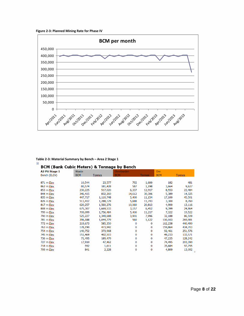
Figure 2-3: Planned Mining Rate for Phase IV
Table 2-3: Material Summary by Bench – Area 2 Stage 1
BCM per month
0
50,000
100,000
150,000
200,000
250,000
300,000
350,000
400,000
450,000
Apr/201
1
Jun/2
011
Aug/20
11
Oct/2
011
Dec/2
011
Feb/
2012
Apr/201
2
Jun/2
012
Aug/20
12
Oct/2
012
Dec/2
012
Feb/
2013
Apr/201
3
Jun/2
013
Aug/20
13

Page 9 of 22
2.3. Open Pit Mine Operation
Mining will be conducted, for the balance of 2011, by Pelly Construction. This includes the Area 2 pit
overburden and waste stripping scheduled for the balance of 2011.
2.3.1. Mine Equipment
Major mining equipment requirements are indicated in Table 2-4; these are based on similar-sized
operations, as well as current practices at the Minto Mine. The proposed plant processing rate of 1.4-
million tonnes per year was used to estimate the mining equipment fleet required. The fleet has an
estimated maximum capacity of 40,000 tpd total material, which will be sufficient for the proposed life-
of-mine plan.
Table 2-4 Mine Equipment (Current Contractor Fleet)
No. of units Equipment Type
1 1
Hitachi EX1200 Shovel Hitachi EX1100 Shovel
8 Cat 777F Haul Truck
1 Cat 992G Loader
2 Cat 385CL Excavator
3 Cat D9T Dozer
2 Cat 16 m Grader
2 Atlas Copco PV235 Drill
1 Atlas Copco D9-11 Drill
1 Cat 777C Water Truck
1 Cat 777B w/trailer
2.3.2. Unit Operations
The Atlas Copco PV235 drills will perform the majority of the production drilling in the mine, with the
smaller Atlas Copco D9 drill used for secondary blasting requirements and may be used on the tighter-
spaced patterns required for pit development blasts.
The main loading and haulage fleet consists of Cat 777F-100 ton haul trucks, which are loaded primarily
with the diesel Hitachi shovels or the Cat 992G wheel loader, depending on pit conditions. As pit
conditions dictate, the Cat D9 dozers are used to rip and push material to the excavators, as well as
maintaining the waste dumps.
The remainder of the equipment listed in Table 2-4 will be used to maintain and build access roads and
to meet various site facility requirements (including coarse mill feed stockpile maintenance and further
exploration development).
The work schedule is based on two 11-hour shifts, seven days a week, 365 days per year.

Page 10 of 22
2.3.3. Grade Control
In order to minimize ore dilution, maximize ore recovery, and thereby improve the operation’s overall
economics, grade control will play an important role throughout the mining process.
Grade control begins with the proper identification of the ore/waste zones and contacts in the field
through:
Information obtained from up-to-date 3-D resource model;
Blast hole sampling;
Driller reports;
Face sampling (includes mapping, visual inspections, sampling); and
Trenching (as required, to provide better definition of ore/waste contacts, sampling).
Once the above information has been gathered and compiled, it will be communicated to operational
personnel through:
Daily/weekly production meetings;
Detailed “dig” maps – outlining ore zones, waste contacts, faults; and
Field surveying and layout of dig limits, ore contacts, trenching required.
In order to maintain the effectiveness of the grade control process; regular field inspections will be
undertaken by engineering/geology personnel. Clear lines of communication will be maintained with
operational personnel, including equipment operators and front line supervisors.
As part of the grade control process, variable bench heights may be necessary in order to maximize the
ore recovery. These include: variable bench heights in waste in order to target the top of the ore zone,
and a varying bench height within the ore zones (reduce height at the periphery of the zone). Drill and
blast control will also play an important role in order to minimize dilution of the ore zones during the
blasting process (e.g. minimize heave in the ore zone).
2.4. Pre-Stripping Schedule
The mine plan anticipated for April 1st to September 30th, 2011 and for the balance of the year consists
primarily of waste stripping. Similar to the current production rate, roughly 400,000 BCM of waste per
month are planned, with roughly one-quarter of the ma terial by volume being overburden soil, more
than half being waste rock with no grade, and the remaining 13% being primarily waste rock with some
grade.
Approximately 3% of the total material in the first three months of stripping is expected to be ore-grade
oxide material. This oxide ore will be stockpiled for future milling and processing. This is the same
procedure that has been applied to oxide ore material mined from the Main Pit as the mill is not
currently configured to handle oxides.
The initial three months of pre-stripping for the Area 2 pit are summarised in Table 2-5.

Page 11 of 22
Table 2-5: Area 2 Initial Pre-stripping
Month (2011) April May June July August September
Activity Overburden
& waste
stripping.
Overburden
& waste
stripping.
Overburden
& waste
stripping.
Overburden
& waste
stripping.
Overburden
& waste
stripping.
Overburden
& waste
stripping.
Overburden (BCM) 193,354 113,833 76,141 70,183 71,640 89,277
Waste Rock - No
Grade (BCM)
174,034 245,893 262,668 273,322 267,419 227,927
Waste Rock - Grade
< 0.64% (BCM)
16,573 32,325 37,901 44,432 44,038 56,474
Ore Material - Low-
Grade Oxide (BCM)
6,037 10,951 13,290 15,063 19,902 16,324
TOTAL MATERIAL
(BCM)
389,997 403,002 390,000 402,999 403,000 390,002
For more details on waste material handling, please see Section 4 of this document.
3. UNDERGROUND MINE PLAN
Exploration at Minto Mine has historically been focused on finding near-surface deposits conducive to
open pit mining. In the course of exploration, several deeper deposits and mineralized areas were
discovered that may provide an opportunity to add mill feed material using underground mining
methods and thereby extending the mine life.
There are several known deposits in the Area 2/118 complex that may have the grade, continuity and
volume to be considered potentially mineable from underground. These deposits have been scheduled
into the Phase IV LOM Schedule submitted as part of the Phase IV Expansion Application.
It should be noted that underground mining can generally be accomplished with a significantly reduced
surficial footprint as compared to open pit mining resulting in potentially reduced environmental
impacts. Closure and reclamation of an underground mine is not as extensive as that required for open
pit mines.
3.1. Mineral Resources
Mineral resources that were considered as part of the underground component of the Phase IV LOM
plan are limited to Area 118 and Area 2. However, there is a potential for future underground
exploitation of Minto East, Wildfire and Copper Keel.

Page 12 of 22
3.1.1. Area 2/118
A number of deposits with underground mining potential are located south and west of, as well as
beneath, the proposed Area 2 Pit at depths of roughly 100 m to 300 m below surface.
3.1.2. Exploration
Additional development beyond these existing underground resources was included in the Phase IV
LOM plan to the Minto East and Wildfire/Copper Keel exploration targets. These exploration declines
were included in order to provide an underground platform for further resource delineation in these
areas.
3.2. Mining Method Description
At this stage, two potential underground mining methods have been proposed for the Area 2/118
underground mining:
Room and Pillar (“RAP”)
Post-Pillar Cut and Fill (“PPCF”)
RAP mining is an open stoping method that utilizes un-mined rock as pillars to support a series of rooms
or small stopes around the pillars. The method allows for excellent production capacity potential and
relatively low cost while still providing mining flexibility and low dilution. The strong, massive nature of
the Minto rock and shallow depth of the deposits mean that extraction ratios of at least 70% to 85%
could reasonably be expected without the use of backfill or artificial support such as concrete posts.
Figure 3-1: Schematic of RAP mining method

Page 13 of 22
PPCF mining is a variation of cut and fill and room and pillar and has the advantage of being able to be
used in thicker (> 10 m), irregular-shaped deposits while keeping dilution and pillar sizes to a minimum.
Figure 3-2: Schematic of PPCF mining method
3.3. Conceptual Mine Design and Operation
3.3.1. Portal
The underground will be accessed via a portal from surface and a decline. The proposed portal location
is in an area of minimal overburden approximately 40 metres south of the proposed Area 2 pit and near
the pit access road.
The portal will be established by removing overburden from the area and then blasting a trench into the
surface bedrock to establish a face of sufficient height to accommodate the portal opening and still have
7-10 metres of good rock in the brow above. The gradient of the rock trench will be -15% toward the
portal, the same as the decline, and will be about 20 metres in length. The portal face of the rock trench
will be inclined at 80° from the horizontal. The sides of the rock trench will each consist of two 55° wall
segments separated by a 3 metre bench located at an elevation 10 metres above the bottom of the
trench.
The overburden will be removed to 2 metres beyond the rock trench and graded to a maximum slope of
2.5:1. The road approaching the rock trench shall be graded at +2%, which is possible since the
topography has a slope of 12-15%; this will promote drainage down the road and away from the rock
trench. A laydown area will also be excavated into the overburden alongside the road. A perimeter
ditch around the outside of the overburden cut will be established to direct rain water flowing down the
hillside away from the portal.

Page 14 of 22
Figure 3-3: Conceptual drawing of portal cut excavation
The rock trench will be supported as required and will at a minimum have 2.4 metre long #6 resin
grouted rebar installed on a 1 metre by 1 metre spacing with welded wire mesh on the portal face.
It is anticipated that it will take approximately one month to excavate and prepare the portal cut.
The portal cut excavation is conceptualised in Figure 3-3 and a drawing showing the excavation is
included as Appendix A.
3.3.2. Future Underground Developments
Further detail regarding the decline, ventilation and underground power supply will be submitted in
future revisions of the General Site Plan.
4. WASTE MANAGEMENT PLAN - SUMMARY
A complete Waste Management Plan (WMP) for Phase IV waste rock and overburden was produced by
EBA Engineering Consultants Ltd. Portions of the WMP relevant to this Stage 1 application are
summarised in this section.
4.1. Types of Waste
Mining operations at the Minto Mine generate three general types of waste materials: overburden,
waste rock and tailings. Overburden includes all unconsolidated soil above the bedrock. Waste rock
consists of rock that is mined, but is below ore cut-off grade, which for Minto’s Phase IV development is
0.64% copper. Tailings consist of material left from processed ore and are outside of the scope of this
WMP.

Page 15 of 22
Overburden and waste rock may be further categorised as follows:
Overburden o Ice-rich o Non ice-rich
Waste Rock o Potentially acid generating (PAG) o Non potentially acid generating (NPAG)
Waste rock is further classified by grade bin as illustrated in Table 4-1.
Table 4-1: Summary of Waste Rock volumes by Grade bin
Grade Bin (% Copper) Total Expected Volume (M m3) ARD Classification
0.00 8.77 NPAG
0.01 – 0.05 0.18 NPAG
0.05 – 0.10 0.18 NPAG
0.10 – 0.20 0.44 PAG
0.20 – 0.64 2.11 PAG
Total 11.68
4.2. Waste Disposal Schedule
All of the Phase IV waste will be disposed in the following five dump sites:
The South Wall Buttress of the Main Pit;
The Mill Valley Fill Expansion – Stages 1 and 2;
The Grade Bin 0.10 – 0.64 Disposal Area;
The Southwest Waste Dump Expansion; and
The Area 118 Open Pit.
A summary of dump design volumes, material sources and schedule are presented in Table 4-2.

Page 16 of 22
Table 4-2: Waste Dump Schedule and Volumes
Dump Design Volume (M m3)
Grade Bin
(%Cu)
Waste Type Material Source
Schedule
Main Pit South Wall Buttress
1.30 0.00 – 0.64
Waste Rock Area 2 Open Pit
April to July
2011
Simultaneous Disposal with Tailings in Main Pit
1.38 (minimum)
0.10 – 0.64
Waste Rock Area 2 and Area
118 Open Pits and
Underground
July 2011 to
September 2013
Mill Valley Fill Expansion 1.30 0.00 Waste Rock Area 2 Open Pit
April to October
2011
Grade Bin 0.10 – 0.64 Disposal Area
0.93 (maximum)
0.10 – 0.64
Waste Rock Area 2 and Area
118 Open Pits and
Underground
July 2011 to
September 2013
Southwest Expansion Stages 1 & 2 (Waste Rock)
6.44 0.00 – 0.10
Waste Rock Area 2 and Area
118 Open Pits
July 2011 to
October 2013
Southwest Waste Dump Expansion Stage 1 (Overburden Area)
2.78 N/A Non ice-rich Overburden
Area 2 and Area
118 Open Pits
February 2011 to
April 2013
Area 118 Open Pit 0.30 0.00 – 0.10
Waste Rock Area 2 Open Pit ,
Area 2 and Area
118 Underground
July 2012
TOTAL 14.47 M m3
Note that any ice-rich material will report to the current Ice Rich Overburden Dump (IROD). The volume
of ice-rich material expected is minimal.
The waste dump and structure footprints are shown on the EBA drawing WMP-01 in Appendix B.
Planned waste production for Phase IV is summarised in the chart in Figure 4-1. In this chart, “Int-Grade
Waste” and “High-Grade Waste” are PAG material, whereas “Low-Grade Waste” and “Zero-Grade
Waste” are NPAG.

Page 17 of 22
Figure 4-1: Waste Material Schedule – Summary by Type ( Weekly for 3 months, then monthly for Duration of Area 2 pit)

Page 18 of 22
Table 4-3: Waste Dump Locations planned for 180 day period and beyond
4.3. Waste Dumps Pertaining to Stage 1
The waste dumps that are planned for this Stage 1 application period (April 2011 through June 2011)
are:
Main Pit South Wall Buttress
Mill Valley Fill Expansion
Southwest Waste Dump Expansion Stage 1 (Overburden Area)
The design considerations for these dumps are summarised in the following sections. Table 4-3: Waste Dump Volume Capacities planned for 180 day period
Seq. Dump BCM's Elev (m) avg Proportion Notes
1 Valley Fill 1,200,000 757.5 28% Clean Waste
2 In-Pit Buttress 1,500,400 810 34% Clean,LG & HG Waste
3 S-W Dump 1,673,487 885 38% Clean Waste & OB
TOTAL 4,373,887 100%

Page 19 of 22
4.3.1. Main Pit South Wall Buttress
The construction of a new South wall buttress for the Main Pit is to stabilize the South wall of the pit
that is currently in an unstable condition. Waste rock of Grade Bins 0.00 to 0.64% Cu generated from
Area 2 Open Pit is to be used for construction of the south wall buttress. The waste management plan
for this site is focused on short-term slope stability. Slope stability analyses were performed for cases of
surface slope and deep-seated slope failures in a short-term (mine operation) period and long-term
period (after closure) and in the design seismic event of an annual probability of 1 in 475 years (1/475).
The waste will be sub-aqueous at closure. Thus, metal leaching/transportation is not an issue. Surface
water management for the south wall buttress is not required as the waste rock is confined by the pit.
Surface water management will be addressed in Subsection 4.5 “Grade Bin 0.10 to 0.64 Disposal Area”.
The Main Pit South Wall Buttress will be covered by tailings and water at closure. The top portion of the
wall buttress material (above the design pond water level Elevation 786.0 m) will be pushed into the pit
at closure, if required.
A plan showing the Main Pit South Wall Buttress is included in Appendix B - MINTO MINESITE WMP
WASTE DUMPS PLAN VIEW INCL. SW BUTTRESS as EBA drawing WMP-06.
4.3.2. Mill Valley Fill Expansion
The Mill Valley Fill (MVF) Expansion consists of two fills: an extension of the existing MVF (referred to as
MVF Extension) and an expansion of the existing camp fill pad. The MVF Expansion will be constructed
of Grade Bin 0.00 material to reduce the potential for transportation of metals. The design volume of
the MVF Expansion is approximately 1.5 Mm3 based on the slope crest elevation of 770 m. The
construction of the MVF Expansion is also intended to provide a toe berm to reduce the ground
movement occurring in the adjacent Dry Stack Tailings Storage Facility area located to the south. The
design of the expansion involves the construction of drainage systems, excavation and backfill of a toe
key with waste rock, construction of water conveyance structures, placement of a drainage blanket and
placement of general waste rock.
Drainage systems for the MVF Expansion will consist of a drainage blanket placed directly beneath the
general rock fill to prevent the build-up of porewater pressures within the fill and to allow water to
continue to flow down the Minto Creek valley. The drainage blanket will be 10 m thick and constructed
using select waste rock with D10 > 6 mm to allow free drainage. Although most of the waste rock is
generally considered to be free draining and suitable for use as drain blanket material, this material
should meet the specifications provided by EBA and will be approved by an engineer prior to placement
on site.
The toe key will extend a minimum of 10 m below the existing ground or to bedrock, whichever is
shallowest. The purpose of the toe key is to provide stability against deep seated failure by forcing a
failure deeper into the foundation soils. The toe key will be backfilled with general rock fill.

Page 20 of 22
Water conveyance structures will be constructed at the toe, which consist of a dyke with low permeable
clay, an impacted water return line, and an inverted culvert collection point. The toe key will be used to
collect water from the existing collect point W-8A.
Waste rock will be placed by the end dump method and nominally packed with the spreading
equipment. The general fill will not meet the specifications for engineered fill; thus, only temporary
structures can be constructed on the completed surface of the MVF Expansion.
The MVF Expansion will be graded to drain water from west to east. A grade of 5 percent should be
maintained from the crest of the MVF Expansion to the crest of the existing Mill Valley Fill. This grade
follows the grade of the existing access road.
At closure, any buildings on the MVF Expansion will be removed. All of the terrace slopes in the MVF
Extension will be re-graded to 3H:1V.
Surface of the fill will be covered with overburden soil. The overburden will be vegetated with local
vegetation to reduce the potential for erosion. The finished ground surface will be graded at 5% percent
to allow surface water to drain to the east at closure.
The surface drainage system will be upgraded at closure. A west-east trunk drainage ditch will be
installed to allow water flowing through the valley.
A plan of the Mill Valley Fill Expansion is included in Appendix B as EBA drawing WMP-08.
4.3.1. Southwest Waste Dump Expansion
The Southwest Waste Dump Expansion is located immediately to the west of the existing Southwest
Waste Dump. The purpose of the Southwest Waste Dump (SWD) Expansion is to provide additional
storage area for overburden and waste rock mined from the Area 2 and Area 118 Open Pits.
The SWD Expansion consists of two stages:
Stage 1 includes an overburden area near the existing Reclamation Overburden Dump and a waste rock area to the east.
Stage 2 consists of a waste rock area on the south side of Stage 1 and west of the existing waste placement.
The overburden placed in the SWD Expansion Overburden Area will be non ice-rich overburden. Ice-rich
overburden will be disposed of in the Ice-Rich Overburden Dump.
Surface water management will include drainage structures for the overburden area. Surface ditches or
swales will be constructed to promote positive drainage of precipitation and run-on water off the SWD
Expansion. A grade of 2% for the dump surface will be maintained to allow surface water to drain to the
east during the operational life of the mine.

Page 21 of 22
Prior to closure, it is expected that some of the overburden material will be transported to the other
waste disposal areas for use as surface cover material (growth media). Therefore, the final geometry of
the overburden dump area will be subject to change.
At closure, all of the terrace slopes in the SWD Expansion will be re-graded to 2H:1V. The overburden
will be vegetated with local vegetation to reduce the potential for erosion. The dump surface will be
graded to 2% to allow surface water to drain to the east at closure.
The drainage ditches may be kept in place or re-routed pending actual surface conditions at closure.
4.4. General Site Preparation and Monitoring
It is expected that all of waste materials will be trucked into the dump sites and unloaded by using the
end dump method. Bulldozers may be utilized to spread out the materials for a rough grading purpose.
The dump sites are to be built up in lifts. The thickness of each lift is approximately 10 m. Rough
grading is required for each lift in order to facilitate surface runoffs and traffic during construction. A
diversion ditch will be created if a natural drainage path is intercepted by the dump sites.
The current site monitoring program includes both slope stability and water quality monitoring. The
slope stability monitoring is focused on the south wall of the Main Pit, Dry Stack Tailings Storage Facility
and Southwest Waste Dump. The water quality monitoring is performed through water sampling
points. The current monitoring program is expected to continue through the operational life of the
mine.
Additional visual monitoring of stability of the side slopes on all dump sites should be incorporated in
the above mentioned monitoring program, and should be performed on a regular basis. Maintenance or
termination of the monitoring program in post-closure will be decided at the closure stage.
5. TAILINGS
A Preliminary Tailings Management Plan for Phase IV was prepared by EBA Engineering Consultants Ltd.
and was previously submitted as part of the Phase IV Expansion Application.
6. HEALTH, SAFETY AND EMERGENCY PLANNING
As an operational mine, MintoEx has comprehensive health and safety and emergency response plans in
place. These have been revisited and revised as required to address any additional expected risks
associated with Phase IV – primarily the move to include underground mining activities.
These protocols and plans are presented in the Emergency Response Plan: see attached documentation,
Minto Mine ERP ( Emergency Response Plan).