general purpose, pulse and dc transient suppression phe448 ... · general purpose, pulse and dc...
TRANSCRIPT

© KEMET Electronics Corporation • P.O. Box 5928 • Greenville, SC 29606 (864) 963-6300 • www.kemet.com F3038_PHE448 • 5/19/2015 1One world. One KEMET
Benefits
• Rated voltage: 1,600 – 2,000 VDC• Rated voltage: 650 – 700 VAC• Capacitance range: 0.0001 – 0.022 µF • Lead spacing: 15 mm• Capacitance tolerance: ±5%, other tolerances on request• Climatic category: 55/105/56, IEC 60068–1• Tape and reel packaging in accordance with IEC 60286–2• RoHS Compliant and lead-free terminations• Categorytemperaturerangeof-55˚Cto+105˚C
Overview
ThePHE448Seriesisacapacitorwithpolypropylenefilmdielectric and metal foil electrodes, encapsulated in self-extinguishing resin in a box of material meeting the requirements of UL 94 V–0.
Applications
Typical applications include high frequency and high voltage applications requiring capacitors with extremely high current handling capability, i.e., high dV/dt values.
General Purpose, Pulse and DC Transient Suppression
PHE448 Series Polypropylene Film/Foil, Radial
Legacy Part Number System
PHE448 R B 4150 J R06Series Rated Voltage (VDC) Lead Spacing (mm) Capacitance Code (pF) Capacitance
Tolerance Packaging
Polypropylene Film/Foil R = 1,600 S = 2,000
B = 15.0 The last three digits representsignificantfigures.Thefirstdigit
specifiesthetotalnumberof digits.
J = ±5% Other tolerances on
request
See Ordering Options Table
New KEMET Part Number System
F 448 B D 152 J 1K6 CCapacitor Class Series Lead Spacing (mm) Size Code Capacitance Code
(pF)Capacitance
ToleranceRated Voltage
(VDC) Packaging
F = Film Polypropylene Film/Foil
B = 15.0 See Dimension Table
First two digits represent significant
figures.Thirddigitspecifies
number of zeros.
J = ±5%, Other tolerances
on request
1K6 = 1,600 2K0 = 2,000
See Ordering Options Table
© KEMET Electronics Corporation • P.O. Box 5928 • Greenville, SC 29606 (864) 963-6300 • www.kemet.com F3038_PHE448 • 5/19/2015 2
Film CapacitorsGeneral Purpose, Pulse and DC Transient Suppression – PHE448 Series Polypropylene Film/Foil, Radial
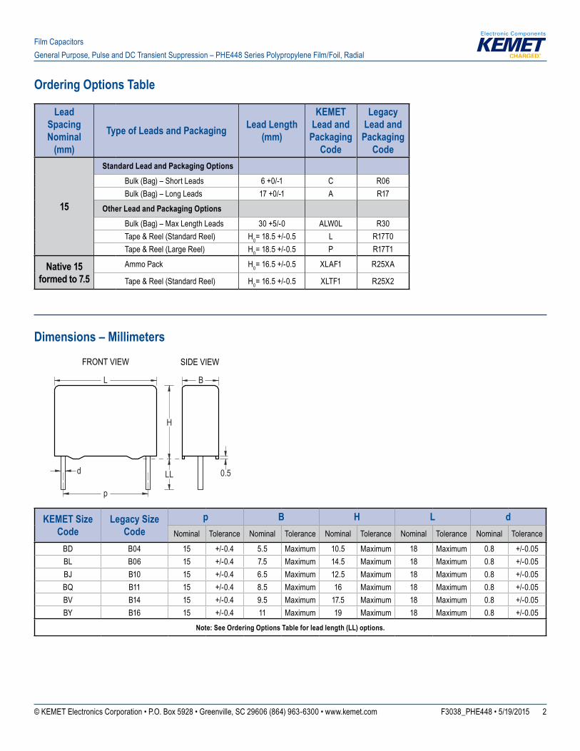
Ordering Options Table
Lead SpacingNominal
(mm)
Type of Leads and Packaging Lead Length(mm)
KEMET Lead and
Packaging Code
Legacy Lead and
Packaging Code
15
Standard Lead and Packaging OptionsBulk (Bag) – Short Leads 6+0/-1 C R06Bulk (Bag) – Long Leads 17+0/-1 A R17
Other Lead and Packaging OptionsBulk (Bag) – Max Length Leads 30+5/-0 ALW0L R30Tape & Reel (Standard Reel) H0=18.5+/-0.5 L R17T0Tape & Reel (Large Reel) H0=18.5+/-0.5 P R17T1
Native 15 formed to 7.5
Ammo Pack H0=16.5+/-0.5 XLAF1 R25XA
Tape & Reel (Standard Reel) H0=16.5+/-0.5 XLTF1 R25X2
Dimensions – Millimeters
L B
H
d
p
LL 0.5
FRONT VIEW SIDE VIEW
KEMET Size Code
Legacy Size Code
p B H L dNominal Tolerance Nominal Tolerance Nominal Tolerance Nominal Tolerance Nominal Tolerance
BD B04 15 +/-0.4 5.5 Maximum 10.5 Maximum 18 Maximum 0.8 +/-0.05BL B06 15 +/-0.4 7.5 Maximum 14.5 Maximum 18 Maximum 0.8 +/-0.05BJ B10 15 +/-0.4 6.5 Maximum 12.5 Maximum 18 Maximum 0.8 +/-0.05BQ B11 15 +/-0.4 8.5 Maximum 16 Maximum 18 Maximum 0.8 +/-0.05BV B14 15 +/-0.4 9.5 Maximum 17.5 Maximum 18 Maximum 0.8 +/-0.05BY B16 15 +/-0.4 11 Maximum 19 Maximum 18 Maximum 0.8 +/-0.05
Note: See Ordering Options Table for lead length (LL) options.
© KEMET Electronics Corporation • P.O. Box 5928 • Greenville, SC 29606 (864) 963-6300 • www.kemet.com F3038_PHE448 • 5/19/2015 3
Film CapacitorsGeneral Purpose, Pulse and DC Transient Suppression – PHE448 Series Polypropylene Film/Foil, Radial
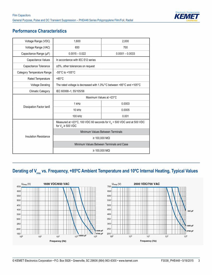
Performance Characteristics
Voltage Range (VDC) 1,600 2,000
Voltage Range (VAC) 650 700
Capacitance Range (µF) 0.0015 – 0.022 0.0001 – 0.0033
Capacitance Values In accordance with IEC E12 series
Capacitance Tolerance ±5%, other tolerances on request
Category Temperature Range -55°Cto+105°C
Rated Temperature +85°C
Voltage Derating Theratedvoltageisdecreasedwith1.3%/°Cbetween+85°Cand+105°C
Climatic Category IEC 60068–1, 55/105/56
DissipationFactortanδ
MaximumValuesat+23°C
1 kHz 0.0003
10 kHz 0.0005
100 kHz 0.001
Insulation Resistance
Measuredat+23°C,100VDC60secondsforVR < 500 VDC and at 500 VDC for VR≥500VDC
Minimum Values Between Terminals
≥100,000MΩ
Minimum Values Between Terminals and Case
≥100,000MΩ
Derating of Vrms vs. Frequency, +85ºC Ambient Temperature and 10ºC Internal Heating, Typical Values
© KEMET Electronics Corporation • P.O. Box 5928 • Greenville, SC 29606 (864) 963-6300 • www.kemet.com F3038_PHE448 • 5/19/2015 4
Film CapacitorsGeneral Purpose, Pulse and DC Transient Suppression – PHE448 Series Polypropylene Film/Foil, Radial
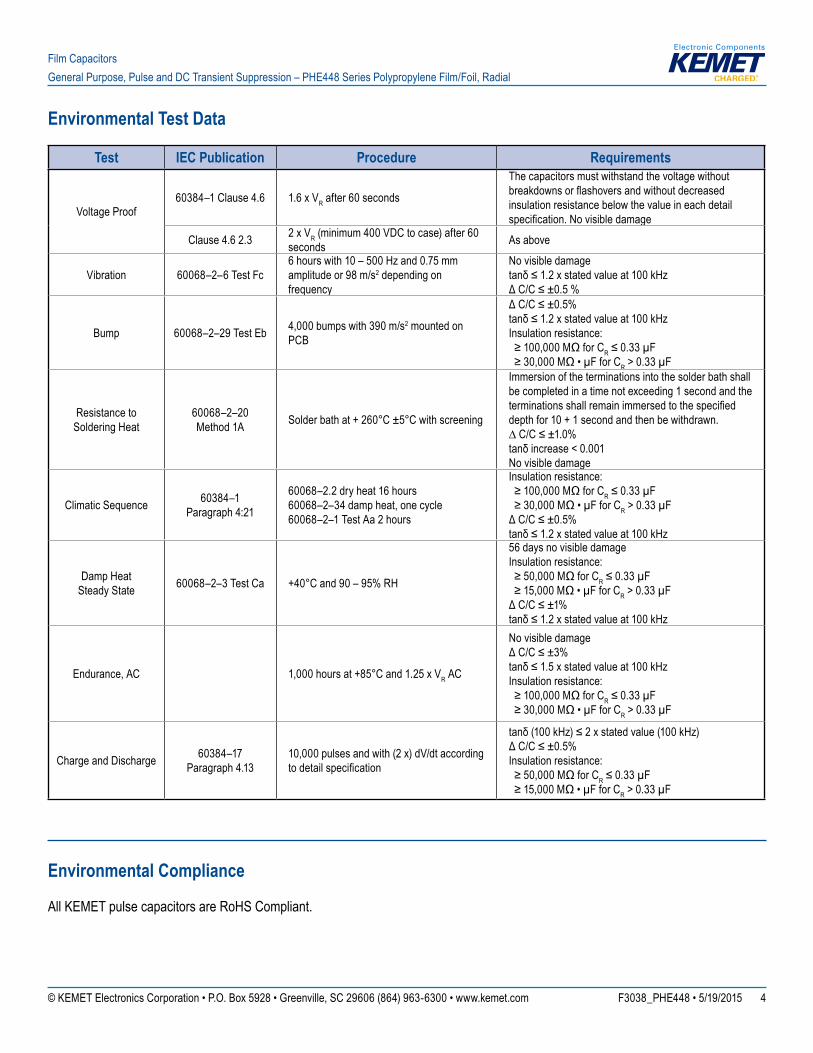
Environmental Test Data
Test IEC Publication Procedure Requirements
Voltage Proof60384–1 Clause 4.6 1.6 x VR after 60 seconds
The capacitors must withstand the voltage without breakdownsorflashoversandwithoutdecreasedinsulation resistance below the value in each detail specification.Novisibledamage
Clause 4.6 2.3 2 x VR (minimum 400 VDC to case) after 60 seconds As above
Vibration 60068–2–6 Test Fc6 hours with 10 – 500 Hz and 0.75 mm amplitude or 98 m/s2 depending on frequency
No visible damage tanδ≤1.2xstatedvalueat100kHz ΔC/C≤±0.5%
Bump 60068–2–29 Test Eb 4,000 bumps with 390 m/s2 mounted on PCB
ΔC/C≤±0.5% tanδ≤1.2xstatedvalueat100kHz Insulation resistance: ≥100,000MΩforCR≤0.33µF ≥30,000MΩ•µFforCR > 0.33 µF
Resistance to Soldering Heat
60068–2–20 Method 1A Solderbathat+260°C±5°Cwithscreening
Immersion of the terminations into the solder bath shall be completed in a time not exceeding 1 second and the terminationsshallremainimmersedtothespecifieddepthfor10+1secondandthenbewithdrawn. ∆C/C≤±1.0%tanδincrease<0.001 No visible damage
Climatic Sequence 60384–1 Paragraph 4:21
60068–2.2 dry heat 16 hours 60068–2–34 damp heat, one cycle 60068–2–1 Test Aa 2 hours
Insulation resistance: ≥100,000MΩforCR≤0.33µF ≥30,000MΩ•µFforCR > 0.33 µFΔC/C≤±0.5% tanδ≤1.2xstatedvalueat100kHz
Damp Heat Steady State 60068–2–3 Test Ca +40°Cand90–95%RH
56 days no visible damage Insulation resistance: ≥50,000MΩforCR≤0.33µF ≥15,000MΩ•µFforCR > 0.33 µF ΔC/C≤±1% tanδ≤1.2xstatedvalueat100kHz
Endurance, AC 1,000hoursat+85°Cand1.25xVR AC
No visible damage ΔC/C≤±3% tanδ≤1.5xstatedvalueat100kHz Insulation resistance: ≥100,000MΩforCR≤0.33µF ≥30,000MΩ•µFforCR > 0.33 µF
Charge and Discharge 60384–17 Paragraph 4.13
10,000 pulses and with (2 x) dV/dt according todetailspecification
tanδ(100kHz)≤2xstatedvalue(100kHz) ΔC/C≤±0.5% Insulation resistance: ≥50,000MΩforCR≤0.33µF ≥15,000MΩ•µFforCR > 0.33 µF
Environmental Compliance
All KEMET pulse capacitors are RoHS Compliant.

© KEMET Electronics Corporation • P.O. Box 5928 • Greenville, SC 29606 (864) 963-6300 • www.kemet.com F3038_PHE448 • 5/19/2015 5
Film CapacitorsGeneral Purpose, Pulse and DC Transient Suppression – PHE448 Series Polypropylene Film/Foil, Radial
Table 1 – Ratings & Part Number Reference
VDC VACCap
Value (µF)
Dimensions in mm Lead Spacing
(p)
dV/dt (V/µs)
Size Code (New/Legacy)
Rthha ºC/W 85ºC
0.2m/s
New KEMET Part Number
Legacy Part NumberB H L
1600 650 0.0015 5.5 10.5 18.0 15 15000 BD/B04 87 F448BD152J1K6(1) PHE448RB4150J(1)1600 650 0.0018 5.5 10.5 18.0 15 15000 BD/B04 86 F448BD182J1K6(1) PHE448RB4180J(1)1600 650 0.0022 5.5 10.5 18.0 15 15000 BD/B04 84 F448BD222J1K6(1) PHE448RB4220J(1)1600 650 0.0027 6.5 12.5 18.0 15 15000 BJ/B10 82 F448BJ272J1K6(1) PHE448RB4270J(1)1600 650 0.0033 6.5 12.5 18.0 15 15000 BJ/B10 82 F448BJ332J1K6(1) PHE448RB4330J(1)1600 650 0.0039 6.5 12.5 18.0 15 15000 BJ/B10 82 F448BJ392J1K6(1) PHE448RB4390J(1)1600 650 0.0047 6.5 12.5 18.0 15 15000 BJ/B10 82 F448BJ472J1K6(1) PHE448RB4470J(1)1600 650 0.0056 7.5 14.5 18.0 15 15000 BL/B06 78 F448BL562J1K6(1) PHE448RB4560J(1)1600 650 0.0068 7.5 14.5 18.0 15 15000 BL/B06 78 F448BL682J1K6(1) PHE448RB4680J(1)1600 650 0.0082 8.5 16.0 18.0 15 15000 BQ/B11 70 F448BQ822J1K6(1) PHE448RB4820J(1)1600 650 0.01 8.5 16.0 18.0 15 15000 BQ/B11 70 F448BQ103J1K6(1) PHE448RB5100J(1)1600 650 0.012 9.5 17.5 18.0 15 15000 BV/B14 60 F448BV123J1K6(1) PHE448RB5120J(1)1600 650 0.015 9.5 17.5 18.0 15 15000 BV/B14 60 F448BV153J1K6(1) PHE448RB5150J(1)1600 650 0.018 11.0 19.0 18.0 15 15000 BY/B16 55 F448BY183J1K6(1) PHE448RB5180J(1)1600 650 0.022 11.0 19.0 18.0 15 15000 BY/B16 55 F448BY223K1K6(2) PHE448RB5220K(2)2000 700 0.0001 5.5 10.5 18.0 15 25000 BD/B04 87 F448BD101J2K0(1) PHE448SB3100J(1)2000 700 0.00012 5.5 10.5 18.0 15 25000 BD/B04 87 F448BD121J2K0(1) PHE448SB3120J(1)2000 700 0.00015 5.5 10.5 18.0 15 25000 BD/B04 87 F448BD151J2K0(1) PHE448SB3150J(1)2000 700 0.00018 5.5 10.5 18.0 15 25000 BD/B04 87 F448BD181J2K0(1) PHE448SB3180J(1)2000 700 0.00022 5.5 10.5 18.0 15 25000 BD/B04 87 F448BD221J2K0(1) PHE448SB3220J(1)2000 700 0.00027 5.5 10.5 18.0 15 25000 BD/B04 87 F448BD271J2K0(1) PHE448SB3270J(1)2000 700 0.00033 5.5 10.5 18.0 15 25000 BD/B04 86 F448BD331J2K0(1) PHE448SB3330J(1)2000 700 0.00039 5.5 10.5 18.0 15 25000 BD/B04 86 F448BD391J2K0(1) PHE448SB3390J(1)2000 700 0.00047 5.5 10.5 18.0 15 25000 BD/B04 86 F448BD471J2K0(1) PHE448SB3470J(1)2000 700 0.00056 5.5 10.5 18.0 15 25000 BD/B04 85 F448BD561J2K0(1) PHE448SB3560J(1)2000 700 0.00068 5.5 10.5 18.0 15 25000 BD/B04 85 F448BD681J2K0(1) PHE448SB3680J(1)2000 700 0.00082 5.5 10.5 18.0 15 25000 BD/B04 85 F448BD821J2K0(1) PHE448SB3820J(1)2000 700 0.001 5.5 10.5 18.0 15 25000 BD/B04 84 F448BD102J2K0(1) PHE448SB4100J(1)2000 700 0.0012 6.5 12.5 18.0 15 25000 BJ/B10 82 F448BJ122J2K0(1) PHE448SB4120J(1)2000 700 0.0015 6.5 12.5 18.0 15 25000 BJ/B10 82 F448BJ152J2K0(1) PHE448SB4150J(1)2000 700 0.0018 7.5 14.5 18.0 15 25000 BL/B06 78 F448BL182J2K0(1) PHE448SB4180J(1)2000 700 0.0022 8.5 16.0 18.0 15 25000 BQ/B11 70 F448BQ222J2K0(1) PHE448SB4220J(1)2000 700 0.0027 8.5 16.0 18.0 15 25000 BQ/B11 70 F448BQ272J2K0(1) PHE448SB4270J(1)2000 700 0.0033 9.5 17.5 18.0 15 25000 BV/B14 60 F448BV332J2K0(1) PHE448SB4330J(1)
VDC VAC Cap Value (µF)
B (mm)
H (mm)
L (mm)
Lead Spacing (p)
dV/dt (V/µs)
Size Code (New/Legacy)
Rthha ºC/W 85ºC 0.2m/s
New KEMET Part Number
Legacy Part Number
(1) Insert lead and packaging code. See Order Options Table for available options.(2) K = ±10% (only available tolerance).

© KEMET Electronics Corporation • P.O. Box 5928 • Greenville, SC 29606 (864) 963-6300 • www.kemet.com F3038_PHE448 • 5/19/2015 6
Film CapacitorsGeneral Purpose, Pulse and DC Transient Suppression – PHE448 Series Polypropylene Film/Foil, Radial
Manual Soldering Recommendations
Following is the recommendation for manual soldering with a soldering iron.
The soldering iron tip temperature should be set at350°C(+10°Cmaximum)withthesolderingduration not to exceed more than 3 seconds.
Recommended Soldering Temperature
0
50
100
150
200
250
300
350
400
0 1 2 3 4 5 6 7 8
Soldering time (sec)
Sold
erin
g iro
n bi
t tem
pera
ture
(deg
C)
Soldering Process
The implementation of the RoHS directive has resulted in the selection of SnAgCu (SAC) alloys or SnCu alloys as primary solder. This has increased the liquidus temperature from that of 183ºC for SnPb eutectic alloy to 217 – 221ºC for the new alloys. As a result, the heat stress to the components, even in wave soldering, has increased considerably due to higher pre-heat and wave temperatures. Polypropylene capacitors are especially sensitive to heat (the melting point of polypropylene is 160 – 170ºC). Wave soldering can be destructive, especially for mechanically small polypropylene capacitors (with lead spacing of 5 mm to 15 mm), and great care has to be taken during soldering. The recommendedsolderprofilesfromKEMETshouldbeused.PleaseconsultKEMETwithanyquestions.Ingeneral,thewavesolderingcurvefrom IEC Publication 61760-1 Edition 2 serves as a solid guideline for successful soldering. Please see Figure 1.
Reflowsolderingisnotrecommendedforthrough-holefilmcapacitors.Exposingcapacitorstoasolderingprofileinexcessoftheabovetherecommended limits may result to degradation or permanent damage to the capacitors.
Do not place the polypropylene capacitor through an adhesive curing oven to cure resin for surface mount components. Insert through-holepartsafterthecuringofsurfacemountparts.ConsultKEMETtodiscusstheactualtemperatureprofileintheoven,ifthrough-holecomponents must pass through the adhesive curing process. A maximum two soldering cycles is recommended. Please allow time for the capacitor surface temperature to return to a normal temperature before the second soldering cycle.
Wave Soldering Recommendations
0
50
100
150
200
250
300
0 40 80 120 160 200 240
Tem
pera
ture
(°C
)
Time (s)
ca 2°C/s
ca 3.5°C/s typical
ca 5°C/s
Cooling
2+3s max
115°C maxTpreheat
ΔT <150°C
100°C
Preheating
Typical
First wave Second wave
260°C

© KEMET Electronics Corporation • P.O. Box 5928 • Greenville, SC 29606 (864) 963-6300 • www.kemet.com F3038_PHE448 • 5/19/2015 7
Film CapacitorsGeneral Purpose, Pulse and DC Transient Suppression – PHE448 Series Polypropylene Film/Foil, Radial
Soldering Process cont'd
Wave Soldering Recommendations cont'd1. The table indicates the maximum set-up temperature of the soldering processFigure 1
Dielectric Film Material
Maximum Preheat Temperature
Maximum Peak Soldering
Temperature
Capacitor Pitch
≤10mm
Capacitor Pitch
= 15 mm
Capacitor Pitch
> 15 mm
Capacitor Pitch
≤15mm
Capacitor Pitch
> 15 mm
Polyester 130°C 130°C 130°C 270°C 270°C
Polypropylene 100°C 110°C 130°C 260°C 270°C
Paper 130°C 130°C 140°C 270°C 270°C
Polyphenylene Sulphide 150°C 150°C 160°C 270°C 270°C
2. The maximum temperature measured inside the capacitor: Set the temperature so that inside the element the maximum temperature is below the limit:
Dielectric Film Material Maximum temperature measured inside the element
Polyester 160°C
Polypropylene 110°C
Paper 160°C
Polyphenylene sulphide
160°C
Temperature monitored inside the capacitor.
Selective Soldering Recommendations
Selectivedipsolderingisavariationofreflowsoldering.Inthismethod,theprintedcircuitboardwiththrough-holecomponentstobesolderedispreheatedandtransportedoverthesolderbathasinnormalflowsolderingwithouttouchingthesolder.Whentheboardisover the bath, it is stopped and pre-designed solder pots are lifted from the bath with molten solder only at the places of the selected components, and pressed against the lower surface of the board to solder the components.
Thetemperatureprofileforselectivesolderingissimilartothedoublewaveflowsolderingoutlinedinthisdocument,however, instead of two baths, there is only one bath with a time from 3 to 10 seconds. In selective soldering, the risk of overheating is greater than indoublewaveflowsoldering,andgreatcaremustbetakensothatthepartsarenotoverheated.

© KEMET Electronics Corporation • P.O. Box 5928 • Greenville, SC 29606 (864) 963-6300 • www.kemet.com F3038_PHE448 • 5/19/2015 8
Film CapacitorsGeneral Purpose, Pulse and DC Transient Suppression – PHE448 Series Polypropylene Film/Foil, Radial
Construction
Detailed Cross SectionSelf-Extinguishing
ResinMolded Plastic
CaseMolded Plastic
Case
Leads
Metal Contact Layer
Metal Contact Layer
Margin
Margin
Margin
Metal Foil(Second Layer)
Metal Foil(Fourth Layer)
Polypropylene Film(First Layer)
Polypropylene Film(Third Layer)
Single-sided Metallized
Polypropylene Film
FILM WINDING SCHEME OPTIONS
1 Section
Single-sided Metallized
Polypropylene Film
Single-sided Metallized
Polypropylene Film
Single-sided Metallized
Polypropylene Film
Single-sided Metallized Polypropylene Film
2 Sections
3 Sections 4 Sections
Single-sided Metallized
Polypropylene Film
Polypropylene Film Dielectric
1 Section
Double-sided Metallized Polyester Film
3 Sections
Double-sided Metallized
Polyester Carrier Film
Polypropylene Film Dielectric
Double-sided Metallized
Polyester Carrier Film
2 Sections
Polypropylene Film DielectricDouble-sided
Metallized Polyester Carrier
Film
Single-sided Metallized
Polypropylene Film
4 Sections
Polypropylene Film DielectricDouble-sided
Metallized Polyester Carrier
Film
Polypropylene Film Dielectric
1 Section
Polypropylene Film/Foil
2 Sections
Metal Foil Metal Foil
Single-sided Metallized
Polypropylene Film
Polypropylene Film Dielectric
Metallized Polyphenylene Sulfide Film with
Vacuum-Evaporated Aluminum Electrodes
1 Section
Metallized Polyphenylene Sulfide Film (SMR)
Metallized Impregnated
Paper
1 Section
Metallized Impregnated Paper
Single-sided Metallized Polyester
Film
1 Section
Single-sided Metallized Polyester Film
Polypropylene Film Dielectric
1 Section
AXIAL - Polypropylene Film/Foil
2 Sections
Metal Foil
Single-sided Metallized
Polypropylene Film
Polypropylene Film DielectricMetal Foil
Single-sided Metallized
Polypropylene Film
2 Sections
Polypropylene Film Dielectric
Double-sided Metallized
Polyester Carrier Film
Single-sided Metallized
Polypropylene Film
1 Section
AXIAL - Single-sided Metallized Polypropylene Film
Single-sided Metallized Polyester
Film
1 Section
AXIAL - Single-sided Metallized Polyester Film
AXIAL - Double-sided Metallized Polyester Film
Winding Scheme

© KEMET Electronics Corporation • P.O. Box 5928 • Greenville, SC 29606 (864) 963-6300 • www.kemet.com F3038_PHE448 • 5/19/2015 9
Film CapacitorsGeneral Purpose, Pulse and DC Transient Suppression – PHE448 Series Polypropylene Film/Foil, Radial
Marking
Capacitance
TOPFRONT
Capacitance Tolerance
Rated VoltageManufacturing
Date Code
Series
Packaging Quantities
KEMET Size Code
Legacy Size Code
Lead Spacing
Thickness (mm)
Height(mm)
Length (mm)
BulkShort Leads
BulkLong Leads
Standard Reel
ø 360 mm
Large Reelø 500 mm
Standard Reel
Formed
AmmoFormed
BD B04
15
5.5 10.5 18 1000 800 600 1200 550 570BE B05 5.5 12.5 18 1000 800 600 1200 550 570BL B06 7.5 14.5 18 800 400 400 800 350 378BJ B10 6.5 12.5 18 1000 600 500 1000 450 480BQ B11 8.5 16 18 600 400 400 800 350 324BM B12 8 15 18 600 400 400 800 350 351BV B14 9.5 17.5 18 500 300 350 700 250 297BG B15 6 12 18 1000 800 500 1000 450 520BY B16 11 19 18 450 250 300 600 250 252BU B17 13 12.5 18 400 300 250 500 200 216

© KEMET Electronics Corporation • P.O. Box 5928 • Greenville, SC 29606 (864) 963-6300 • www.kemet.com F3038_PHE448 • 5/19/2015 10
Film CapacitorsGeneral Purpose, Pulse and DC Transient Suppression – PHE448 Series Polypropylene Film/Foil, Radial
Lead Taping & Packaging (IEC 60286–2)
Taping Specifi cation
Dimensions in mm Standard IEC 60286–2
Lead spacing +6/-0.1 F 5 7.5 Formed 7.5 10 15 22.5 27.5 FCarrier tape width +/-0.5 W 18 18 18 18 18 18 18 18+1/-0.5
Hold-down tape width +/-0.3 W0 9 9 9 12 12 12 12Position of sprocket hole +/-0.5 W1 9 9 9 9 9 9 9 9+0.75/-0.5
Distance between tapes Maximum W2 3 3 3 3 3 3 3 3Sprocket hole diameter +/-0.2 D0 4 4 4 4 4 4 4 4Feed hole lead spacing +/-0.3 P0
(1) 12.7 12.7 12.7(4) 12.7 12.7 12.7 12.7 12.7Distance lead – feed hole +/-0.7 P1 3.85 3.75 3.75 7.7 5.2 5.3 5.3 P1
Deviation tape – plane Maximum ∆p 1.3 1.3 1.3 1.3 1.3 1.3 1.3 1.3Lateral deviation Maximum ∆h 2 2 2 2 2 2 2 2
Total thickness +/-0.2 t 0.7 0.7 0.7 0.7 0.7 0.9MAX 0.9MAX 0.9MAX
Sprocket hole/cap body Nominal H0(2) 18.5+/-0.5 18.5+/-0.5 18.5+/-0.5 18.5+/-0.5 18.5+/-0.5 18.5+/-0.5 18.5+/-0.5 18+2/-0
Sprocket hole/top of cap body Maximum H1(3) 32 31 43 43 43 58 58 58MAX
(1) Maximum cumulative feed hole error, 1 mm per 20 parts.(2) 16.5 mm available on request.
(3) Depending on case size.(4) 15 mm available on request.
Lead Spacing 5 mm Lead Spacing 7.5 mm
Lead Spacing 10 – 15mm Lead Spacing 22.5 – 27.5 mm
Formed Leads from 10 and 15 mm to 7.5 mm
0 0
0 0
0

© KEMET Electronics Corporation • P.O. Box 5928 • Greenville, SC 29606 (864) 963-6300 • www.kemet.com F3038_PHE448 • 5/19/2015 11
Film CapacitorsGeneral Purpose, Pulse and DC Transient Suppression – PHE448 Series Polypropylene Film/Foil, Radial
H
TW
Lead Taping & Packaging (IEC 60286–2) cont'd
Ammo Specifi cations
SeriesDimensions (mm)
H W TR4x,R4x+R,R7x,RSB
360 340 59F5A, F5B, F5DF6xx, F8xx
PHExxx, PMExxx, PMRxxx, SMR & PFR 330 330 50
Reel Specifi cations
SeriesDimensions (mm)
D H WR4x,R4x+R,R7x,RSB
355500
3025 55 (Max)F5A, F5B, F5D
F6xx, F8xxPHExxx, PMExxx, PMRxxx,
SMR & PFR360500 30 46 (Max)
Manufacturing Date Code (IEC–60062)
Y = Year, Z = MonthYear Code Month Code2000 M January 12001 N February 22002 P March 32003 R April 42004 S May 52005 T June 62006 U July 72007 V August 82008 W September 92009 X October O2010 A November N2011 B December D2012 C2013 D2014 E2015 F2016 H2017 J2018 K2019 L2020 M
D
W
H

© KEMET Electronics Corporation • P.O. Box 5928 • Greenville, SC 29606 (864) 963-6300 • www.kemet.com F3038_PHE448 • 5/19/2015 12
Film CapacitorsGeneral Purpose, Pulse and DC Transient Suppression – PHE448 Series Polypropylene Film/Foil, Radial
KEMET Corporation World Headquarters
2835 KEMET WaySimpsonville, SC 29681
Mailing Address:P.O. Box 5928 Greenville, SC 29606
www.kemet.com Tel: 864-963-6300 Fax: 864-963-6521
Corporate Offi cesFort Lauderdale, FLTel: 954-766-2800
North America
SoutheastLake Mary, FLTel: 407-855-8886
NortheastWilmington, MATel: 978-658-1663
CentralNovi, MITel: 248-306-9353
WestMilpitas, CATel: 408-433-9950
Mexico Guadalajara, Jalisco Tel: 52-33-3123-2141
Europe
Southern EuropeSasso Marconi, ItalyTel: 39-051-939111
Skopje, MacedoniaTel: 389-2-55-14-623
Central EuropeLandsberg, Germany Tel: 49-8191-3350800
Kamen, GermanyTel: 49-2307-438110
Northern EuropeHarlow, United Kingdom Tel: 44-1279-460122
Espoo, FinlandTel: 358-9-5406-5000
Asia
Northeast AsiaHong KongTel: 852-2305-1168
Shenzhen, ChinaTel: 86-755-2518-1306
Beijing, ChinaTel: 86-10-5877-1075
Shanghai, ChinaTel: 86-21-6447-0707
Seoul, South KoreaTel: 82-2-6294-0550
Taipei, TaiwanTel: 886-2-27528585
Southeast AsiaSingaporeTel: 65-6701-8033
Penang, MalaysiaTel: 60-4-6430200
Bangalore, IndiaTel: 91-806-53-76817
Note: KEMET reserves the right to modify minor details of internal and external construction at any time in the interest of product improvement. KEMET does not assume any responsibility for infringement that might result from the use of KEMET Capacitors in potential circuit designs. KEMET is a registered trademark of KEMET Electronics Corporation.
© KEMET Electronics Corporation • P.O. Box 5928 • Greenville, SC 29606 (864) 963-6300 • www.kemet.com F3038_PHE448 • 5/19/2015 13
Film CapacitorsGeneral Purpose, Pulse and DC Transient Suppression – PHE448 Series Polypropylene Film/Foil, Radial
DisclaimerAllproductspecifications,statements,informationanddata(collectively,the“Information”)inthisdatasheetaresubjecttochange.Thecustomerisresponsibleforcheckingandverifying the extent to which the Information contained in this publication is applicable to an order at the time the order is placed.
All Information given herein is believed to be accurate and reliable, but it is presented without guarantee, warranty, or responsibility of any kind, expressed or implied.
StatementsofsuitabilityforcertainapplicationsarebasedonKEMETElectronicsCorporation’s(“KEMET”)knowledgeoftypicaloperatingconditionsforsuchapplications,butarenotintendedtoconstitute–andKEMETspecificallydisclaims–anywarrantyconcerningsuitabilityforaspecificcustomerapplicationoruse.TheInformationisintendedforuseonlyby customers who have the requisite experience and capability to determine the correct products for their application. Any technical advice inferred from this Information or otherwise provided by KEMET with reference to the use of KEMET’s products is given gratis, and KEMET assumes no obligation or liability for the advice given or results obtained.
Although KEMET designs and manufactures its products to the most stringent quality and safety standards, given the current state of the art, isolated component failures may still occur. Accordingly, customer applications which require a high degree of reliability or safety should employ suitable designs or other safeguards (such as installation of protective circuitry or redundancies) in order to ensure that the failure of an electrical component does not result in a risk of personal injury or property damage.
Although all product–related warnings, cautions and notes must be observed, the customer should not assume that all safety measures are indicted or that other measures may not be required.