general purpose integrating spheres · satellite integrating spheres ... general purpose...
TRANSCRIPT

General Purpose Integrating SpheresIntroduction........................................................................................................ 1
Unpacking and Inspection................................................................................. 3
Standard Product General Purpose Integrating Spheres .............................. 4Mounting Options.................................................................................. 5Port Configurations ............................................................................... 6Baffling.................................................................................................. 7Calibration ............................................................................................. 7
General Purpose Sphere Port Fixtures ............................................................ 9Port Plugs............................................................................................. 10Port Reducers....................................................................................... 11Port Frame Reducers ........................................................................... 11Port Frame Expanders ......................................................................... 12Fiber Optic Port Adapters.................................................................... 12
Integrating Sphere Attachments..................................................................... 14Sphere Detector Assemblies................................................................ 15Satellite Integrating Spheres................................................................ 19Filter Holders....................................................................................... 19Sample Holders ................................................................................... 21Cosine Diffuser Assemblies ................................................................ 22CBA-100-SF Cone Baffle ................................................................... 23Variable Attenuators ............................................................................ 24SM-050 Sphere Monitor...................................................................... 27
General Purpose Sphere Applications ........................................................... 28Temperature Considerations ................................................................ 28Measuring Total Flux of an LED......................................................... 29Measuring Laser Power ....................................................................... 31Uniform Source Sphere ....................................................................... 32Measuring Reflectance or Transmittance ............................................ 34
Maintenance ..................................................................................................... 36
Appendix A Typical Reflectance Values ........................................................ 37
Appendix B Reflectance Material Care and Handling Guidelines.............. 41
AQ-00001-000, Rev. 6
Introduction
Labsphere general purpose integrating spheres (GPS) are optical devices capable of a wide range of appli-cations. The underlying properties of their design are easy to understand and form the basis of their versa-tility. General purpose integrating spheres collect electromagnetic radiation from a source completely external to the optical device, usually for the purpose of flux measurement or optical attenuation. Radiation introduced into an integrating sphere strikes the reflective walls and undergoes many diffuse reflections. After numerous reflections, the radiation is dispersed very uniformly at the sphere walls. The resulting integrated radiation level is directly proportional to the initial radiation level and may be measured easily, using a sphere detector.
Our standard product integrating spheres are fabricated or coated from one of three diffusely reflective materials: Spectralon®, Spectraflect® and Infragold®. Occasionally Duraflect or Infragold-LF coatings may be applied to a custom product. The Spectraflect, Infragold, Duraflect and Infragold-LF reflective surfaces are applied as coatings. Theses spheres are constructed of two separate hemispheres, each interior covered with the corresponding highly reflective coating. Spectralon is a highly Lambertian, thermoplastic material that can be machined into a wide variety of shapes. Spectralon integrating spheres are constructed of two hemispheres bolted together and surrounded by a sheet metal shroud.
The integrating sphere product line at Labsphere has been upgraded. Some of the older sphere models offered in the past are no longer sold due to low demand. Sphere attachments have been modified, and rou-tinely operated fasteners now require metric tooling. The old integrating sphere attachments and port fix-tures will fit the port frames on a new integrating sphere design, however, the new port frame attachments are not compatible with the old Labsphere integrating spheres. The set screws on the old products accepted
AQ-00001-000, Rev. 6 1

a 0.035-inch allen wrench. The newer version products now require a 1.5 mm allen wrench. This instruc-tion manual applies to all Labsphere standard product integrating spheres manufactured since the mid-year 2004. If your integrating sphere includes an older product version, the information herein still applies except where noted. If your system includes a custom product that operates differently than our standard products, additional information is provided in the system manual. Operating procedures for sphere-mounted illuminators are provided in the separate instruction manual entitled Halogen Light Sources.
AQ-00001-000, Rev. 6 2

Unpacking and Inspection
Your integrating sphere was thoroughly inspected before shipping and should be ready to operate after completing the set-up instructions. All Labsphere instrumentation is packaged and shipped in reinforced shipping containers. Carefully check the components after unpacking for any damage that may have occurred during shipping. If there is any such damage, file a claim immediately with the freight carrier and contact the Labsphere Customer Service Department at
(603) 927-4266.
The general purpose sphere is sold as a single item without port accessories or mounting attachments. All optional components ordered with the general purpose sphere will be listed on the packing list accompany-ing the shipment.
AQ-00001-000, Rev. 6 3

Standard Product General Purpose Integrating Spheres
The general purpose spheres, as the name implies, are designed for flexibility rather than specificity. A general purpose sphere can perform the typical integrating sphere tasks with reasonable accuracy, but can-not match the performance of the standard Labsphere uniform source, light measurement and reflectance measurement integrating sphere systems. Furthermore, some of these tasks require a sphere calibration. In these cases, a more suitable uniform source or lamp measurement system may be more cost-effective than the general purpose sphere alternative.
When choosing a standard product sphere, port size and input flux are the most important considerations. The smaller diameter, less expensive spheres necessarily have smaller utility ports and very high through-put. The port fraction of the smaller spheres, however, is very high. Consequently, the measurement data generated from a small integrating sphere will be less accurate than the same application using a large sphere. The larger integrating sphere exhibit less throughput than the smaller spheres, and high optical attenuation. These spheres are more flexible but, at the same time, are more expensive to manufacture.
Labsphere offers a number of standard product general purpose spheres that meet the needs of most appli-cations. These spheres are categorized by the number of utility ports, the internal diameter and the reflec-tance material at the internal surface. The sphere exteriors for the 1 and 2-inch diameter standard product are shaped in the form of a cube. The larger diameter spheres are surrounded by two aluminum hemi-spheres that either constitute the coating substrate in the case of a Spectraflect or Infragold reflecting sur-face, or provide outer mechanical integrity to a sphere constructed of Spectralon.
The effective spectral range of Spectraflect coating is 350 - 2400 nm, although the hemispherical reflec-tance falls off above 1850 nm. A Spectraflect coated sphere is adequate for most radiation measurement applications and the 3P series sphere constitutes the most popular general purpose sphere design. The high
AQ-00001-000, Rev. 6 4

reflectance properties of Spectralon is best suited for low level light applications. Spectralon exhibits high hemispherical reflectance over the spectral range 250 - 2500 nm, with reflectance greater than 99% between 400 nm and 1500 nm. One distinct advantage of the Spectralon spheres is reliability: Spectralon does not deteriorate with age and can be easily cleaned. Infragold is an electrochemically plate, diffuse gold-metallic coating that exhibits high reflectance over the infrared wavelength region from 0.7 to 20 µm.
Mounting OptionsA general purpose sphere can mount to either a Labsphere base plate or a standard optical breadboard. Any mounting devices for the integrating sphere, however, must be purchased as an option. The illustration in Figure 1 summarizes the mounting options. If the breadboard is metric, M6 adapter and metric mounting post attachments are required. The mounting attachments are the same for all general purpose spheres.
4P-GPS-060-SF GeneralPurpose Sphere
1/4-20 to M6 Adapter
1/4-20
1/4-20M6
1/4-20 Mounting Post(4 Sizes Available)
Base Plate
1/4-20 Post Holder(2 Sizes Available)
M6 Post Holder(2 Sizes Available)
M6 Mounting Post(4 Sizes Available)
Figure 1. Sphere mounting options for either the Labsphere base plate or a standard English or metric optical breadboard. The base plate is available in the 1/4-20 mounting configuration.
AQ-00001-000, Rev. 6 5
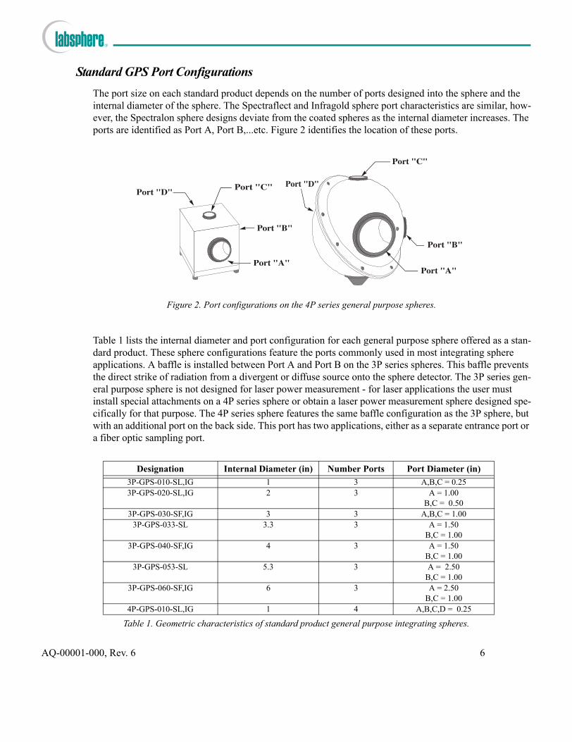
Standard GPS Port ConfigurationsThe port size on each standard product depends on the number of ports designed into the sphere and the internal diameter of the sphere. The Spectraflect and Infragold sphere port characteristics are similar, how-ever, the Spectralon sphere designs deviate from the coated spheres as the internal diameter increases. The ports are identified as Port A, Port B,...etc. Figure 2 identifies the location of these ports.
Table 1 lists the internal diameter and port configuration for each general purpose sphere offered as a stan-dard product. These sphere configurations feature the ports commonly used in most integrating sphere applications. A baffle is installed between Port A and Port B on the 3P series spheres. This baffle prevents the direct strike of radiation from a divergent or diffuse source onto the sphere detector. The 3P series gen-eral purpose sphere is not designed for laser power measurement - for laser applications the user must install special attachments on a 4P series sphere or obtain a laser power measurement sphere designed spe-cifically for that purpose. The 4P series sphere features the same baffle configuration as the 3P sphere, but with an additional port on the back side. This port has two applications, either as a separate entrance port or a fiber optic sampling port.
Designation Internal Diameter (in) Number Ports Port Diameter (in)
3P-GPS-010-SL,IG 1 3 A,B,C = 0.253P-GPS-020-SL,IG 2 3 A = 1.00
B,C = 0.503P-GPS-030-SF,IG 3 3 A,B,C = 1.00
3P-GPS-033-SL 3.3 3 A = 1.50B,C = 1.00
3P-GPS-040-SF,IG 4 3 A = 1.50B,C = 1.00
3P-GPS-053-SL 5.3 3 A = 2.50B,C = 1.00
3P-GPS-060-SF,IG 6 3 A = 2.50B,C = 1.00
4P-GPS-010-SL,IG 1 4 A,B,C,D = 0.25
Table 1. Geometric characteristics of standard product general purpose integrating spheres.
Figure 2. Port configurations on the 4P series general purpose spheres.
AQ-00001-000, Rev. 6 6

The integrating sphere designs in Table 1 are offered as standard products. Custom sphere designs are available through your Labsphere sales representative.
Custom Designed General Purpose SpheresAny general purpose integrating sphere not listed in Table 1 falls under the category of a custom GPS. A custom sphere assembly usually is identified by the adding the prefix "CSTM" in front of the normal GPS designation. A customized sphere assembly can differ from the standard product by sphere diameter, port configuration, baffling, reflectance material, or mounting hardware. Unless specified otherwise by the cus-tomer, port frames on custom sphere assemblies accept the same port fixtures and sphere attachments as on the standard product GPS assemblies.
BafflingBaffling in general purpose spheres routinely serves to restrict direct radiation of light at one port from reaching another port, usually the detector port. Another related purpose of baffling is to prevent a detector at one port from viewing first strike specular radiation at another location on the sphere wall. All the gen-eral purpose spheres in Table 1 feature a single baffle mounted roughly halfway between Port A, the largest port on the sphere, and the adjacent Port B. Baffles employed in Spectraflect or Infragold integrating spheres are constructed of aluminum and coated with the corresponding reflectance material. Baffles used in Spectralon integrating spheres are constructed of Spectralon. In all cases, the size and shape of each baf-fle is minimized to preserve radiative uniformity within the sphere.
CalibrationIf your a calibration was performed on your general purpose sphere, the documentation will accompany the system at delivery. The documentation specifies the exact configuration of the sphere assembly during the calibration - this is the only configuration under which the calibration data is valid. Calibrations per-formed at Labsphere are traceable to the National Institute of Standards and Technology (NIST).
4P-GPS-020-SL,IG 2 4 A =1 .00B,C,D = 0.50
4P-GPS-030-SF,IG 3 4 A,B,C,D = 1.004P-GPS-033-SL 3.3 4 A = 1.50
B,C,D = 1.004P-GPS-040-SF,IG 4 4 A = 1.50
B,C,D = 1.004P-GPS-053-SL 5.3 4 A = 2.50
B,C,D = 1.004P-GPS-060-SF,IG 6 4 A = 2.50
B,C,D = 1.00
Designation Internal Diameter (in) Number Ports Port Diameter (in)
Table 1. Geometric characteristics of standard product general purpose integrating spheres.
AQ-00001-000, Rev. 6 7

StorageLabsphere integrating spheres should be stored in a dry, clean storage location at a temperature between 45F and 80F. Do not leave Spectralon integrating spheres in an environment where temperature could drop below 45F or structural damage to the assembly may result. The Spectraflect reflectance coating is soluble in water and may degrade in humid environments. The attachments on an integrating sphere should be removed and port plugs installed when storing the assembly for an extended period of time.
AQ-00001-000, Rev. 6 8

General Purpose Sphere Port Fixtures
Depending upon the size and purpose of your general purpose sphere, a number of port fixtures may be included with your shipment. Port fixtures are items that form an integral part of a general purpose sphere but must be specified by the customer at the time of order and purchased as separate units. Normally, a fix-ture is coated with the same reflectance material as the corresponding general purpose sphere. Fixtures enable the integrating sphere to perform the user’s specific tasks and include items such as port plugs, port reducers, port frame reducers, and fiber optic port adapters. The appropriate tool kit is provided in a ship-ment whenever a port fixture is included with a general purpose sphere.
Each port on a Labsphere integrating sphere is fitted with an aluminum port frame, black anodized on the outside, coated with a reflective material on the inside, and swaged onto the machined surface of the sphere wall. Port frames are not identical for all general purpose spheres, but the circular flange that serves as the mounting fixture is universal. A 1-inch diameter port reducer, for example, will fit on any 1-inch port frame regardless of sphere size or construction.
The nomenclature for integrating sphere port fixtures identifies the part according to its function, port size and reflectance surface. The part PP-025-SL, for example, is a Spectralon port plug that fits a 0.25-inch port frame. The part identified as PR-200-0500-IG is an Infragold-coated port reducer that shrinks a 2.0-inch port to 1/2-inch diameter. A port frame reducer designated PFR-FM/M-200-150-FB reduces the 2.0-inch port and port frame on a sphere to a 1.5-inch diameter. The FB designation indicates the reflectance side of the part is painted in flat black.
AQ-00001-000, Rev. 6 9

The employment of port fixtures increases the versatility of a general purpose sphere. A large Spectraflect general purpose sphere with four ports and the appropriate port fixtures, for example, can perform the same tasks as a smaller integrating sphere design with only three ports. In most cases, the increased flexi-bility using port fixtures can be realized with only minimal added expense. The availability of Spectralon port fixtures, however, is very limited. Port plugs are available for all size ports on any Spectralon integrat-ing sphere. A PFR-FM/M-150-100-SL port frame reducer is available to fit the 1.5-inch diameter port on the 3P-GPS-033-SL general purpose sphere, and the entire line of fiber optic port adapters are compatible with the Spectralon one-inch port frame. Some port fixture examples are provided in Figure 3.
Port PlugsGeneral purpose integrating spheres are fitted with a variety of standard size ports spread strategically about the perimeter of the sphere. Some of these ports may be unnecessary for a certain applications. A port plug must be installed over any unused port in order to maintain light-tight integrity of the sphere and maintain sphere throughput. An additional purpose of a port plug is to keep dust or debris from entering the sphere cavity. A port plug is available for every port size on your general purpose sphere and in any sphere reflectance material or coating.
Port plugs should be handled carefully to avoid damage to the reflective surface. Do not touch the reflective surface with your bare hands.
Spectraflect and Infragold port plugs are coated with the reflectance material on the inside surface of the
PFR-FM/M-100-050-SFPort Frame Reducer
PR-100-0500-SFPort Reducer
PP-100-SFPort Plug
4P-GPS-060-SF GeneralPurpose Sphere
PA-FCPC-100-SF/SLFiber Optic Port Adapter
PA-SMA-100-SF/SLPort AdapterFiber Optic
PA-ST-100-SF/SLPort AdapterFiber Optic
PA-LC-100-SF/SLPort AdapterFiber Optic
Figure 3. Standard Labsphere port fixtures for general purpose, uniform source and interior access inte-grating spheres. All fixtures are available in Spectraflect, Infragold or flat black.
AQ-00001-000, Rev. 6 10

plug assembly. This reflective surface is flat in geometric profile, quite acceptable with a Spectraflect or Infragold integrating sphere. The reflective surface on a Spectralon port plug, however, protrudes into the outer surface of the sphere enclosure, engaging the curvature of the sphere cavity. All port plugs fasten to the outer port frame on an integrating sphere port or a port frame reducer by two M3 set screws. The set screws accept a 1.5 mm allen wrench.
Port ReducersA port reducer mounts directly onto a port frame, reducing the clear aperture of the port to a specified diameter. There is no exposed port frame on a port reducer, however, the perimeter of the port reducer aperture is very thin so that back-scattering is minimized. One of three coatings are available: Spectraflect, Infragold or flat black. There are no port reducers manufactured for Spectralon spheres.
Port reducers should be handled carefully to avoid damage to the reflective coating. Do not touch the reflective surface with your bare hands.
The port reducer should be used only as an output or sample port. Spectraflect and Infragold port reducers are coated with the reflectance material on the inside surface of the fixture assembly. The inner surface of the fixture is tapered slightly to approximate the curvature of the sphere cavity. All port reducers fasten to the outer port frame on an integrating sphere port or a port frame reducer by two M3 set screws. The set screws accept a 1.5 mm allen wrench.
Port Frame ReducersA port frame reducer is a fixture that mounts onto a port frame one-inch or larger, effectively reducing the frame and port size to a specified diameter. An example of a port frame reducer is shown in Figure 5. One of three coatings are available: Spectraflect, Infragold or flat black. A PFR-FM/M-150-100-SL port frame
Integrating Sphere
Port Frame
Port ReducerSpectraflect orInfragold Coating
Figure 4. Reducing the port size using a port reducer.
AQ-00001-000, Rev. 6 11

reducer is available to fit the 1.5-inch diameter port on the 3P-GPS-033-SL general purpose sphere, how-ever, no other Spectralon port frame reducers are manufactured.
Port frame reducers should be handled carefully to avoid damage to the reflective coating. Do not touch the reflective surface with your bare hands.
The port frame reducer can be used as a sample port, output, illuminator port or a sphere detector port. Spectraflect, Infragold and flat black port reducers are coated with the reflectance material on the inside surface of the port fixture. The Spectralon surface of the PFR-FM/M-150-100-SL port frame reducer mates with the internal wall of the Spectralon sphere. All port frame reducers fasten to the outer port frame on an integrating sphere port or another port frame reducer by two M3 set screws. The set screws accept a 1.5 mm allen wrench.
Port Frame ExpandersThe port frames on the one-inch diameter general purpose spheres are too small to accept a detector or other one-half inch attachments. A port frame expander modifies a port frame to a larger port frame size. These fixtures are identified according to input and output port frame diameters. A PFE-M/FM-025-050 expander, for example, modifies the original 1/4-inch diameter male frame to fit the female 1/2-inch diam-eter frame on a SDA-050-U detector.
Fiber Optic Port Adapters A series of Spectraflect coated port adapters are available for attaching a standard fiber optic cable to the integrating sphere. Four port adapters are offered as standard product that fit either a 1/2" or 1"-inch diam-eter port: FC/PC, LC, SMA and ST. The LC port adapter features the female end of a standard LC fiber optic connector and is available only in the Spectraflect and flat black coating versions; the FC/PC adapter
Figure 5. Mounting a port frame reducer on a sphere.
AQ-00001-000, Rev. 6 12

houses the FC portion of a standard FC/PC connector. These adapters all fasten to a one-inch or 1/2-inch port frame by two M3 set screws. The set screws accept a 1.5 mm allen wrench.
Fiber optic port adapters should be handled carefully to avoid damage to the reflective coating. Do not touch the reflective surface with your bare hands.
AQ-00001-000, Rev. 6 13
Integrating Sphere Attachments
A sphere attachment is an optical, mechanical or electrical device that attaches to a port frame on an inte-grating sphere and either generates light or measures the radiance or luminance inside the sphere cavity. Labsphere sphere attachments include detector assemblies, filter holders, sample holders, illuminators, variable attenuators and separate satellite integrating spheres. For information on Labsphere illuminator products, the user should refer to the separate instruction manual Halogen Light Sources, Part No. AQ-00846-000.
Not all attachments offered by Labsphere fit directly on each port on every integrating sphere. In general, the Labsphere detector assemblies can fit on any port on any general purpose sphere with the aid of the correct port frame reducer. Furthermore, the one-inch port on the small cubic general purpose spheres will accommodate any Labsphere one-inch port sphere attachment. Finally, any port one-inch diameter or greater on any sphere assembly can accommodate a standard Labsphere IHLS-100 series illuminator, some with the aid of the correct port frame reducer.
The EHLS-100 series external illuminators and VA-100-SC attenuators do not fit directly on each one-inch port due to the port locations relative to the assembly flange on each hemisphere. The VA-100-MIC atten-uator, however, does fit on most of the integrating spheres, thereby accommodating use of an EHLS series illuminator. The information in Table 2 lists the compatibility of Labsphere attachments for each general purpose sphere offered. If an attachment is required for a port not indicated in the right-hand columns, a correctly sized port frame adapter is required.
AQ-00001-000, Rev. 6 14

The FH-100-200 filter holder fits all one-inch diameter ports on the small, cubic integrating spheres. Addi-tionally, the filter holder can be mounted at Port A on the larger spheres when accompanied by a port frame adapter, or any one-inch port on the six-inch diameter spheres. The FH-050-050 filter holder is compatible with any 1/2-inch port or port frame adapter.
Sphere Detector AssembliesLabsphere detector assemblies are designed for use with a Labsphere integrating sphere across a specific wavelength spectrum. Detectors are available for UV/VIS or NIR light applications and for measuring photometric or radiometric radiation. Table 3 lists the part numbers and spectral range for all standard detectors offered by Labsphere.
Sphere Assembly EHLS SeriesIlluminators
VA-100-MICAttenuator
VA-100-SCAttenuator
3P-GPS-030-SF,IG3P-GPS-033-SL B,C C
3P-GPS-040-SF,IG B,C C3P-GPS-053-SL C B,C B,C
3P-GPS-060-SF,IG B,C B,C B,C4P-GPS-030-SF,IG A,B,C,D
4P-GPS-033-SL D B,C,D C,D4P-GPS-040-SF,IG B,C,D
4P-GPS-053-SL C,D B,C,D B,C,D4P-GPS-060-SF,IG D B,C,D C,D
Table 2. The letters in the three right-hand columns refer to the compatible port num-bers for each attachment and general purpose sphere offered.
Detector Part Name Labsphere Part No.
DetectorCharacteristics
Manufacturer’s Part No.
Spectral Range
SDA-050-U AS-02249-000 Silicon Photodiode Hamamatsu S1336-5BQ 190 - 1100 nmSDA-050-P AS-02500-000 Silicon Photodiode Hamamatsu S1336-5BQ 400 - 700 nmGDA-050-U AS-02501-000 Germanium Photodiode Judson Technologies
J16-8SP-R05M-SC800 - 1800 nm
IDA-050-U-C AS-02502-000 InGaAs Photodiode Electro-Optical SystemsIGA-030 (3mm)
1.0 - 1.7 µm
IDA-050-TE AS-02503-000 Cooled InGaAs Photodiode
Electro-Optical SystemsIGA-030-TE1-TO8
1.0 - 1.7 µm
SDA-050-U-RTA-CE AS-02522-100 Silicon Photodiode Hamamatsu S1336-5BQ 190 - 1100 nmSDA-050-P-RTA-CE AS-02522-101 Silicon Photodiode Hamamatsu S1336-5BQ 400 - 700 nm
IDA-050-RTA-CE AS-02522-002 InGaAs Photodiode Electro-Optical SystemsIGA-030 (3mm)
1.0 - 1.7 µm
PDA-050 AS-01018-000 Side-on PMT Hamamatsu HC120w/Power Supply
185 - 900 nm
Table 3. Integrating sphere detector assemblies manufactured by Labsphere.
AQ-00001-000, Rev. 6 15

The assemblies in Table 3 consist of a detector housing and three meter TRIAX signal cable. The detector housing for each detector assembly fastens directly onto a standard Labsphere 1/2-inch port frame by two M3 set screws. The set screws accept a 1.5 mm allen wrench. If your general purpose sphere does not include a 1/2-inch detector port, a suitable port frame reducer fixture may be required. The TRIAX cable connects either to the input signal connector of a Labsphere SC-5500 Integrating Sphere System Control or an input channel on the DM-1000 Detector Multiplexer. The PDA-050 detector includes a high voltage power supply for powering the photomultiplier tube; the IDA-050-U-C includes a thermoelectric cooling controller and power cable.
The sensor elements for the SDA-U, SDA-P, GDA-U and InGaAs detector assemblies are mounted in a cylindrical housing that extends radially from the integrating sphere when attached to the detector port. An illustration of the housing used for these detector assemblies and the resulting field of view for each con-figuration is provided in Figure 6. The cylindrical housing for each detector assembly is the same, how-ever, the insert used in the SDA-P detector accommodates a photopic filter. This filter shapes the incident radiation from a tungsten-halogen light source to match closely the CIE photopic response. The SDA-P is not suitable for electromagnetic radiation outside the visible band.
The right-angle housing for the SDA-050-U-RTA-CE, SDA-050-P-RTA-CE and IDA-050-RTA-CE detec-tor assemblies contain the same detector hardware as the cylindrical housing but provides greater clearance at the front of the integrating sphere for mounting an application. The field of view for the filtered and unfiltered right-angle detector assemblies is identical.
92 51
Figure 6. Filtered and unfiltered versions of the cylindrical detector assemblies.
AQ-00001-000, Rev. 6 16

In most cases, the sphere detector will be removed from the general purpose sphere assembly prior to ship-ment. To install an un-cooled photodiode detector onto a general purpose sphere:
1. Locate the detector port on the integrating sphere. Normally, the detector port is the 1/2-inch or 1-inch diameter location at Port B. On the standard general purpose spheres, Port B is the only acceptable detector port that is baffled. If Port B is a one-inch port, a port frame reducer is required.
2. Slip the sensor end of the housing over the port frame and tighten the two set screws shown in Figure 8 or 9. Along the housing body of the detector assembly an arrow label may be attached for marking the orientation of the detector during calibration. If the arrow is not present, detector orientation does not matter.
51
Figure 7. The right-angle detector housings contain the same detector hardware as the cylindrical ver-sion but provide better clearance at the exit port of a uniform source.
Figure 8. Installing a sphere detector over a port frame reducer. The spacer is included with the detector occasionally to reduce the field of view and radiant flux incident on the detector element.
AQ-00001-000, Rev. 6 17
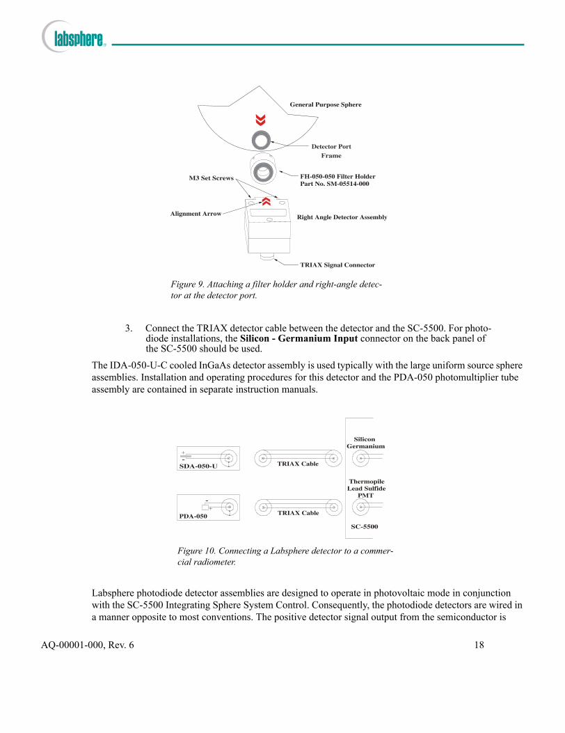
3. Connect the TRIAX detector cable between the detector and the SC-5500. For photo-diode installations, the Silicon - Germanium Input connector on the back panel of the SC-5500 should be used.
The IDA-050-U-C cooled InGaAs detector assembly is used typically with the large uniform source sphere assemblies. Installation and operating procedures for this detector and the PDA-050 photomultiplier tube assembly are contained in separate instruction manuals.
Labsphere photodiode detector assemblies are designed to operate in photovoltaic mode in conjunction with the SC-5500 Integrating Sphere System Control. Consequently, the photodiode detectors are wired in a manner opposite to most conventions. The positive detector signal output from the semiconductor is
Figure 9. Attaching a filter holder and right-angle detec-tor at the detector port.
Figure 10. Connecting a Labsphere detector to a commer-cial radiometer.
AQ-00001-000, Rev. 6 18

wired to the center ring of the detector assembly TRIAX output connector - the negative lead is wired to the center pin. If you decide to connect a Labsphere detector to your own radiometer, you may need to reverse the detector leads. A simple electrical diagram is shown in Figure 10. All Labsphere detector con-nectors are TRIAX configured. You may need an adapter if your radiometer requires a BNC cable.
Satellite Integrating SpheresSatellite spheres are equipped with a 1 or 2-inch diameter attachment port, depending on the diameter of the sphere, and a standard 1-inch illuminator port. The larger sphere may require a port frame reducer for attachment to a general purpose sphere. The internal surface of all Labsphere standard product satellite spheres is Spectraflect. The purpose of these devices is to attenuate light from the illuminator before it reaches the main integrating sphere, or attenuate light flux from the main sphere before it reaches a detec-tor. The latter application requires a port frame reducer at the one-inch illuminator port.
An added bonus to using a satellite integrating sphere is to simulate a Lambertian receptor at the surface of the main sphere. Satellite spheres attach to a main or general purpose integrating sphere in the same fash-ion of other Labsphere attachments. The orientation of the satellite sphere to the main sphere is unimpor-tant, except to facilitate easy access to the attached illuminator or detector.
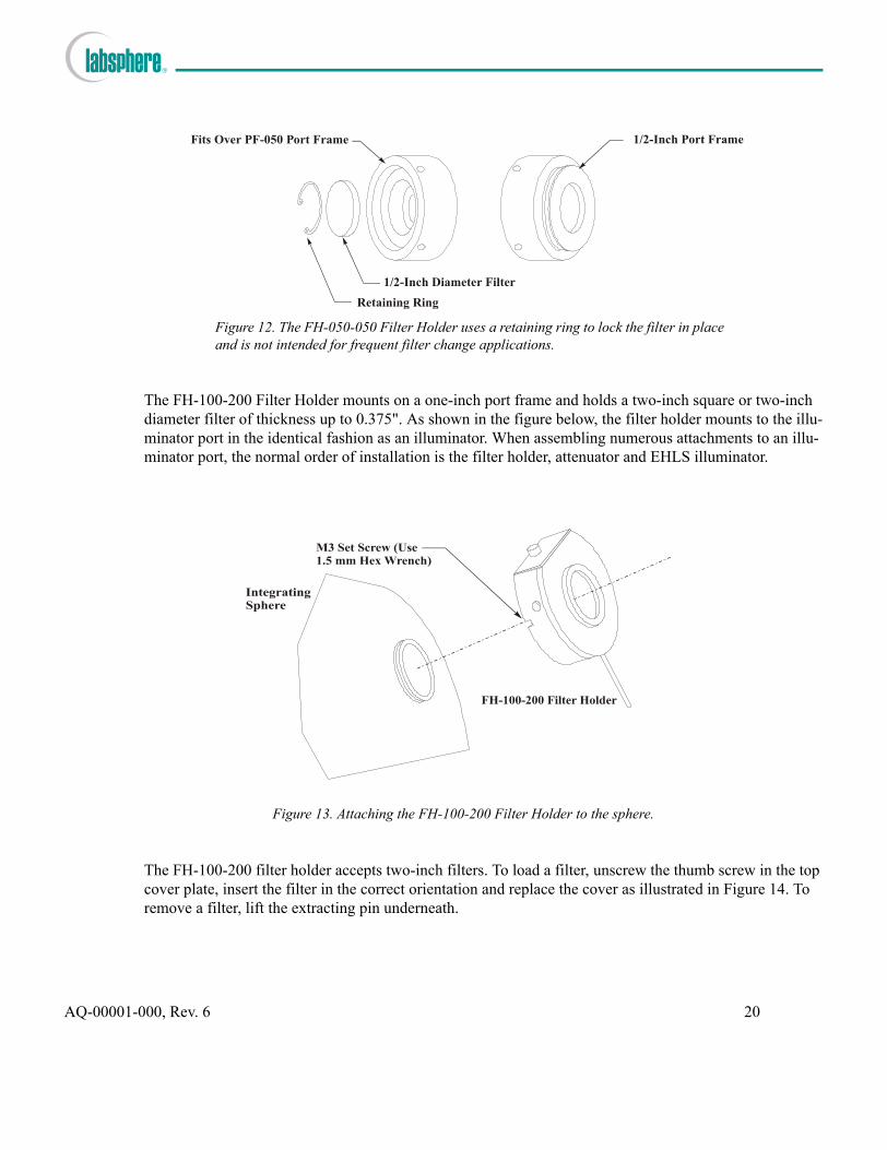
Filter HoldersOccasionally the light emission entering the sphere or sampled by a detector must be conditioned by a fil-ter. The FH-050-050 Filter Holder fits on a 1/2-inch port frame and holds a 1/2-inch diameter filter of thickness up to 0.375". This device is normally used as a permanently installed detector filter.
Figure 11. Attaching a satellite sphere to the main sphere.
AQ-00001-000, Rev. 6 19
The FH-100-200 Filter Holder mounts on a one-inch port frame and holds a two-inch square or two-inch diameter filter of thickness up to 0.375". As shown in the figure below, the filter holder mounts to the illu-minator port in the identical fashion as an illuminator. When assembling numerous attachments to an illu-minator port, the normal order of installation is the filter holder, attenuator and EHLS illuminator.
The FH-100-200 filter holder accepts two-inch filters. To load a filter, unscrew the thumb screw in the top cover plate, insert the filter in the correct orientation and replace the cover as illustrated in Figure 14. To remove a filter, lift the extracting pin underneath.
1/2-Inch Port Frame
Retaining Ring
1/2-Inch Diameter Filter
Fits Over PF-050 Port Frame
Figure 12. The FH-050-050 Filter Holder uses a retaining ring to lock the filter in place and is not intended for frequent filter change applications.
Figure 13. Attaching the FH-100-200 Filter Holder to the sphere.
AQ-00001-000, Rev. 6 20

Labsphere does not manufacture one-inch filter holders for either general purpose or uniform source inte-grating spheres. Instead, we can provide a port adapter for the manual or automatic filter wheel systems available on the open market.
Sample HoldersSpring-loaded sample holders, tailored to each type of sphere coating, are available for mounting a reflec-tance standard or sample at a one-inch port frame. Illustrated in Figure 15, the sample holders consist of three parts: a mounting plate, dovetail slide and spring-loaded clamp.
Filters
Lift to Extract Filter
Cover
Figure 14. Operating the FH-100-200 filter holder.
Sample Shelf
M3 Set Screws
Dovetail Slide
Spring-loadedClamp
2-56 Cap Screws
0 Mounting Plate
8 Mounting Plate
Figure 15. SH-100-0 and SH-100-8 Sample Holder attachments.
AQ-00001-000, Rev. 6 21

Two different mounting plates are available. The standard plate accompanies the SH-100-0 model for posi-tioning the reflecting surface of the sample at normal incidence to the beam as the beam enters the oppos-ing entrance port. The mounting plate for the SH-100-8 model sample holder is wedge-shaped for mounting the sample surface at 8° angle of incidence. The mounting plate fits over any one-inch port frame by tightening the two M2 set screws along the plate perimeter.
Cosine Diffuser AssembliesThe luminance or radiance inside a perfect integrating sphere is very uniform, but the introduction of ports around the sphere perimeter and baffles inside the sphere cavity may distort this uniformity. A strategically placed cosine diffuser at a detector or illuminator port may reduce the impact of these distortions. The cosine diffuser assemblies in Table 4 change the spatial profile of the light collected or emanated at the inner sphere surface.
The attachments in Table 4 mount a 1/2-inch or one-inch opal glass diffuser adjacent to the inner wall of the integrating sphere. The PA-050 diffuser in Figure 16 mounts the opal glass at a detector port, providing the standard 1/2-inch port frame for attaching a detector assembly. The optic is permanently mounted inside the holder assembly. The PA-100-DH diffuser assembly in Figure 17 is designed for a one-inch illu-minator port and requires a male-to-male adapter for installation, Part No. SM-05379-000. The proper employment of diffusers with general purpose spheres can be crucial because the integrating sphere design may not be ideally suited to the application.
The optic held by the PA-100-DH cosine diffuser holder is held by a retaining ring for easy disassembly. When installing the diffuser assembly, the white opal coating should always face the integrating sphere.
Diffuser Assembly Labsphere Part No.
PA-050 AS-02438-004
PA-100-DH AS-02439-008
Table 4. Cosine diffuser attachments for Labsphere integrating spheres.
1/2-Inch Port Frame
0.37-Inch Diameter Diffuser Optic
Fits Over PF-050 Port Frame
Figure 16. The optic in the PA-050 cosine diffuser is permanently mounted with the opal coating facing the integrating sphere.
AQ-00001-000, Rev. 6 22

Opal glass diffusers are susceptible to cracking when exposed to intense heat. Labsphere does not recom-mend using the PA-100-DH diffuser with the EHLS-100 series illuminators. The EHLS illuminators already include a more rugged diffuser optic mounted in the front end cap of the illuminator housing.
CBA-100-SF Cone BaffleThe cone baffle in Figure 18 attaches directly to a one-inch port typically used as an illuminator port. The one-inch port frame on the exposed end of the cone baffle accepts either a satellite integrating sphere or an external illuminator. The baffle obstructs direct view of the port by the port directly opposite the cone baf-fle device.
The cone baffle is useful when attaching high intensity illuminators to an integrating sphere. The device accomplishes the same purpose as the PA-100-DH cosine diffuser but without potential damage to the optic.
Figure 17. Install the diffuser assembly so the opal coating faces the integrating sphere.
Figure 18. The reflective surface of the cone baffle assembly is coated with Spectraflect.
AQ-00001-000, Rev. 6 23

Variable AttenuatorsA variable attenuator is a light limiting device that fits between a light source and an illuminator port on the integrating sphere. Attenuators are categorized by port size and method of operation. The most popular attenuator models are the VA-100-SC and the VA-100-MIC. The motor operated devices are controlled by the Labsphere uniform source control software through the SC-5500 Integrating Sphere System Control and VAC-1000 Variable Attenuator Control instruments, and are adjustable from the fully open to fully closed position in 255 increments. The VA-100-MIC attenuator fits a standard one-inch illuminator port and features a double-opposed knife-edged blades, adjusted by a Vernier scale micrometer. Standard prod-uct attenuators are listed in Table 5 below. If these products do not suit your application, custom variable attenuators can be designed to your specifications.
Motorized Variable Attenuators
The VA-100-SC attenuator is controlled by a stepper motor and gear assembly that position a single atten-uator blade from fully open to fully closed. The motor operates in unipolar mode. A single limit switch inside the motor cover establishes the fully open position. The VA-200-SC attenuator fits onto a 2-inch diameter port frame, but otherwise is identical to the VA-100-SC. The motorized VA-100-SC and VA-200-SC attenuators must be controlled either by the VAC-1000 Variable Attenuator Control instrument, operat-ing under commands from the SS-5500 Integrating Sphere System Control, or a separate customized atten-uator control instrument offered by Labsphere. Attenuator operation depends on the control instrument sending the positioning commands - there is no method of manual controlling either the VA-100-SC or VA-200-SC variable attenuators.
If the control instrument is the VAC-1000, the VA-100-SC or VA-200-SC blade is positioned to one of 255 programmed positions between fully open and fully closed. A limit switch inside the attenuator housing establishes the fully open position, identified as Position No. 0. When the VAC-1000 instrument is turned on, the attenuator motor rotates in the open direction until the limit switch actuates. The attenuator main-tains this blade position until the motor current from the VAC-1000 is stepped in the closed position. The fully closed position is Position No. 255. The uniform source software application displays a slide bar and text box for implementing VA-100-SC or VA-200-SC attenuator control.
Variable Attenuator Labsphere Part No. AdjustmentMechanism
VA-100-SC AS-02450-100 Stepper Motor
VA-200-SC AS-02450-200 Stepper Motor
VA-100-MIC AS-02455-000 Micrometer Head
VA-100-M AS-02567-100 Rotary Knob
VA-200-M AS-02567-200 Rotary Knob
Table 5. Standard product variable attenuators manufactured by Labsphere.
AQ-00001-000, Rev. 6 24

The VA-100-SC or VA-200-SC attenuators can be operated from a custom Labsphere control instrument. In this mode of operation, the stepper motor inside the device can assume any position of up to 12000 motor steps between the fully open and fully closed position.
The VA-100-SC attenuators attach to the illuminator port on an integrating sphere in identical fashion as an illuminator. To mount the attenuator, loosen the M3 set screws shown in Figure 19 with the 1.5 mm allen wrench, slip the attenuator port over the illuminator port frame and re-tighten the set screws. A male-to-male adapter accompanies the VA-100-SC for mounting a lamp or additional attachments at the opposite end. The VA-200-SC attaches to a 2-inch port frame in the same manner. The 2-inch PA-200-M/M male-to-male adapter is Labsphere Part No. SM-05379-016.
Manually Operated Variable Attenuators
The VA-100-MIC delivers the most precise positioning of all Labsphere variable attenuators. This device is manually adjusted by a 0-2 cm micrometer head with Vernier scale, and features two knife-edged oppos-ing attenuator blades. At the 0 cm position, the attenuator port is completely open; at 2.0 cm the port is completely closed.
DB9 Connector
Motor Cover
Attenuator Blade
PA-100-M/M Adapter(Part No. SM-05379-008)M3 Set Screws
(Use 1.5 mm Allen Wrench)
PINOUT1 M12 M23 M34 M45 GRD6 LS7 GRD8 +12VDC9 GRD
One-inch Port Frame
Attach This Side toIntegrating Sphere
Figure 19. The VA-100-SC attenuator must be controlled by the VAC-1000 Variable Attenuator Control or other Labsphere custom instrument.
AQ-00001-000, Rev. 6 25

The VA-100-MIC attaches directly to a one-inch illuminator port frame. To mount the attenuator, loosen the M3 set screws with the 1.5 mm allen wrench, slip the open port on the device over the illuminator port frame and re-tighten the set screws. A male-to-male adapter accompanies the VA-100-MIC for mounting a lamp or additional attachments at the opposite end.
Figure 20. The micrometer adjusted attenuator adjusts the horizontal position of two knife-edged attenuator blades.
Figure 21. Rotary knob controlled VA-100-M attenuator. The VA-200-M atten-uator is similar, but fits on a 2-inch port and is accompanied by the PA-200-M/M adapter.
AQ-00001-000, Rev. 6 26

Two additional variable attenuators are available for integrating sphere applications not requiring the preci-sion provided by the VA-100-MIC. The VA-100-M and VA-200-M attenuator devices use a rotary control method of blade adjustment across a one-inch or two-inch diameter port. An illustration of the VA-100-M is provided in Figure 21.The VA-100-M and VA-200-M attenuators attach to the integrating sphere in the same manner as the VA-100-SC and VA-200-SC devices.
SM-050 Sphere MonitorGeneral purpose spheres are the inexpensive alternative to specific uniform source, light measurement and reflectance measurement integrating spheres manufactured at Labsphere. Labsphere offers a bargain base-ment model radiometer for specific or general purpose radiant flux measurement. The SM-050 Sphere Monitor mounts directly to the new style 1/2-inch diameter detector port frames and displays the sphere illumination in units of radiance, luminance or total flux, depending on the calibration. The sphere monitor operates on power from a 9 volt AC adapter.
An illustration of the sphere monitor is provided in Figure 22. A separate instruction manual accompanies the SM-050 Sphere Monitor when purchased individually or as part of a system. For more information on the SM-050, visit the Labsphere website or contact your Labsphere sales representative.
Figure 22. SM-050 Sphere Monitor.
AQ-00001-000, Rev. 6 27

General Purpose Sphere Applications
General purpose spheres are very flexible and can perform any of the three integrating sphere operations possible: light measurement, reflectance or transmittance characterization, or uniform source applications. The following examples demonstrate this flexibility and provide brief instructions on how a general pur-pose sphere might be utilized.
Temperature ConsiderationsLabsphere reflectance materials and coatings are thermally stable at temperatures up to 100C in the case of Spectraflect or 350C for Spectralon. The Infragold coatings are thermally stable up to 600C. Although the reflectance surfaces are thermally stable at high temperatures, the outer casing of the integrating sphere and sphere attachments may not withstand significant heat, particularly if steep temperature gradients exist across the sphere assembly.
Spectralon material expands and contracts as room temperature changes. At Labsphere, the Spectralon machining process is conducted in a controlled environment at a temperature of 70 + 3F. If a Spectralon integrating sphere is utilized at temperatures outside this range, either the seams inside the sphere cavity may widen if the room temperature is too low, or the user may experience difficulty inserting port attach-ments into the sphere if the temperature is too high. Consequently, Labsphere offers the following temper-ature guidelines for integrating sphere applications.
• For best measurement accuracy, conduct all integrating sphere applications in a well-ventilated space at room temperature between 60 - 80F.
• Do not allow the outer metal surface of Spectraflect or Spectralon integrating spheres
AQ-00001-000, Rev. 6 28

to become too hot to the touch. If the metallic surface does reach this limit, extinguish light sources entering the sphere and allow the sphere assembly to cool down.
• Minimize the time of sphere illumination, where possible, during integrating sphere applications.
• Where the illumination source is a laser, conduct an external laser warm-up before proceeding with sphere operation.
• When utilizing an Infragold coated sphere, it is permissible and sometimes necessary for certain locations on the sphere surface to reach temperatures as high as 100C. Where excessive heat sources are required, mount a temperature measurement device at a strategic location on the outside sphere surface. Consider employing an external cooling device such as an electric fan in your application setup. If temperatures as high as 100C are anticipated for any length of time, a liquid cooled integrating sphere should be considered.
Measuring Total Flux of an LEDA general purpose sphere can be used to measure the total flux emission of a light-emitting diode (LED) using a photodiode detector, radiometer and calibrated LED. LED measurements are possible in units of radiant or luminous flux, or in units relative to the calibrated standard. The light emission of the calibrated LED should be very similar to the LEDs under test, and the detector should be responsive at the wave-lengths concerned. Sphere attenuation is an important issue if the test LEDs are very dim. Otherwise, any GPS model described in the Labsphere catalog or Table 1 of this instruction manual is acceptable for mea-suring light flux.
If the shape of the test source is very different from the calibration source, substitution error may be present in the measurement data obtained. Substitution error is a phenomenon that occurs with integrating
Figure 23. Application setup for measuring total flux from a light-emitting diode.
AQ-00001-000, Rev. 6 29

spheres due to the different absorption characteristics of the test device and the calibrated standard. If the standard is exactly like the device under test, there will be no substitution error and the uncertainty in the measurement data will depend only on the accuracy of the standard calibration and the measurement instrument. If the calibrated standard is different than the test devices, the impact of substitution error can be minimized by employing an auxiliary lamp.
Absolute LED or fiber optic illuminator luminous flux measurements are possible with a general purpose sphere using the Labsphere SC-5500 Integrating Sphere System Control. This instrument serves as a pho-tometer as well as exercising control over integrating sphere systems. The integrating sphere, SC-5500 instrument and detector combination must be calibrated to measure luminous flux and the calibration data must be burned into the SC-5500 EPROM. Additionally, the luminous flux measurements require a photo-pic detector such as the Labsphere SDA-050-P or a SDA-050-U detector and a separate photopic filter. The apparatus should be located in a darkened room:
1. Configure the sphere assembly to the illustration in Figure 23 or as described in the calibration certificate. Port plugs should be installed over Ports C and D, if applica-ble.If measuring the output of an LED, the tip of the test device should be even with the internal surface of the integrating sphere.
2. Energize the source and allow a sufficient warm-up period. 3. Select the luminous flux calibration from the SC-5500 LCD menu. Refer to the cali-
bration documentation when determining the correct calibration factor.4. Extinguish the light source and collect a dark reading from the SC-5500 using the
ZERO feature.5. Energize the light source.6. Record the luminous flux value from the LCD screen.
The following procedure can be used to obtain reasonable accurate radiant flux measurements from a gen-eral purpose integrating sphere using a separately procured radiometer and a calibrated LED. Construct a test setup similar to the one in Figure 23. Port plugs should be installed over Ports C and D, if applicable. If an auxiliary lamp is utilized, the illuminator can be installed at Port C in lieu of the port plug.
1. Install the calibrated LED in the test socket and load the device at the test position. The tip of the LED should be even with the internal surface of the integrating sphere.
2. Record a dark current detector reading I′standard at the radiometer.3. Illuminate the calibrated standard at the correct operating current. Allow the source
sufficient time to warm up and record the detector current Istandard at the radiometer.4. Install the test source in the test socket and load the device at the test position.5. Record a dark current detector reading I′sample at the radiometer.6. Illuminate the test LED at the correct operating current. Allow the source sufficient
time to warm up and record the detector current Isample at the radiometer.7. Calculate the radiant flux using the flux value of the calibrated standard Φstandard:
ΦLEDIsample I′sample–
Is dardtan I′s dardtan–----------------------------------------Φs dardtan=
AQ-00001-000, Rev. 6 30

Measuring Laser PowerA general purpose sphere can be used to measure the total radiant power of a laser beam. This application requires the use of a sphere detector and radiometer. Additionally, the integrating sphere must be calibrated for detector responsivity at the wavelength concerned.
The following procedure can be used to obtain reasonable accurate radiant flux measurements of a laser beam from a general purpose integrating sphere. Construct a setup similar to the one in Figure 24. Port plugs should be installed over Ports A and C during the actual measurement. Port D should be used as the sample port for the laser beam. The apparatus should be located in a darkened room:
1. Remove the port plug at Port A. Energize the laser and align the output beam onto the center of Port A. Once the beam is properly aligned, either close the output aperture at the laser or block the beam by some other method as the laser warms up.
2. Install the port plug over Port A and record a dark current measurement Idark.3. Unblock the laser beam or open the laser output aperture to illuminate the sphere.
Record the detector current Ilaser.
4. Calculate the radiant flux Φlaser using the detector responsivity ℜ(λ) as follows:
Calibrated 4P-GPS-033-SL Integrating Sphere
Port PlugCW Laser
Port Plug
Radiometer
SDA or GDA-U Detector
PFR-FM/M-100-050-SF Port Frame Reducer
PR-100-0500-SFPort Reducer
Figure 24. Application setup for laser power measurement.
AQ-00001-000, Rev. 6 31

Uniform Source SphereA general purpose sphere can be configured as a crude uniform source by introducing illumination into the sphere from an external source. The setup in Figure 25 requires an external illuminator with fiber optic cable, fiber optic port adapter, detector, and radiometer. The 3P-GPS-060-SF is best suited for the uniform source application because a port plug on the far wall on a 4P-GPS-060-SF sphere assembly might inter-fere with output uniformity. The sphere and detector assembly should be calibrated for luminance respon-sivity if the exact luminous output of the sphere must be known. If luminance adjustment is not required, the detector and radiometer can be eliminated from the setup.
The uniform source setup in Figure 26 uses the Labsphere SM-050 Sphere Monitor instead of the standard detector unit and radiometer shown in the previous figure. Additionally, a cosine diffuser is added to the illuminator part where the fiber optic cable attaches to the sphere, and a port reducer decreases the beam size at the exit port of the uniform source.
ΦlaserIlaser Idark–ℜ λ( )
-------------------------=
Figure 25. General purpose sphere configured as a uniform source.
AQ-00001-000, Rev. 6 32

Some large general purpose sphere assemblies can accommodate a variable attenuator and external illumi-nator. For the 3P-GPS-060-SF, no port frame reducer is required at Port B. In Figure 27, a cone baffle is installed at Port B as a coupling device to the integrating sphere so the detector at Port C does not view the light source directly. The cone baffle is a more rugged alternative to the cosine diffuser in Figure 26 when employing an EHLS-100 series illuminator.
The precision or motorized variable attenuator at the illuminator port in Figure 27 adjusts the radiance level inside the sphere. The attenuator shown here is the precision VA-100-MIC. When employing the
Figure 26. Fiber optic uniform source setup with the SM-050 Sphere Monitor.
Figure 27. Typical uniform source setup using a standard EHLS Series illuminator and variable attenuator.
AQ-00001-000, Rev. 6 33

motorized VA-100-SC variable attenuator, the VAC-1000 Variable Attenuator Control and SC-5500 Inte-grating Sphere System Control instruments are required.
Measuring Reflectance or TransmittanceA GPS sphere assembly can be used to measure diffuse reflectance or transmittance of a sample. The application requires a sample holder, light source, reflectance standard, fiber optic sensor cable and array spectrometer. The spectrum of the light source and reflectance standard calibration determines the spectral characteristics of the reflectance or transmittance data generated. If an uncalibrated Spectralon standard is used, the reflectance data in the appendix can be used in lieu of ρstandard to calculate reflectance data for the sample.
If the reflectance characteristics of the sample is very different from the reflectance standard, which most likely is the case, substitution error may be present in the measurement data obtained. Substitution error is a phenomenon that occurs with integrating spheres due to the different in absorption characteristics of the sample loaded at the sample port and the absorption characteristics of the standard. If the standard is exactly like the device under test, there will be no substitution error and the uncertainty in the measurement data will depend only on the accuracy of the standard calibration and the measurement instrument.
The following procedure can be used to obtain reasonable accurate reflectance measurements off a sample loaded at Port A. Construct a setup similar to the one in Figure 28.
To measure diffuse reflectance:1. Energize the light source and align the beam so it passes through Port D unclipped
and is centered on Port A. Allow the source to warm up and either extinguish the light beam or block it from the integrating sphere.
Figure 28. Application setup for measuring diffuse reflectance or transmittance.
AQ-00001-000, Rev. 6 34

2. Load the reflectance standard in the sample holder at Port A. Record a dark scan reading I′standard at the array spectrometer.
3. Unblock the light beam and illuminate the integrating sphere. Record the standard array scan Istandard at the spectrometer instrument.
4. Either extinguish the light beam or block it from the integrating sphere.5. Replace the standard with the reflectance sample. Record a dark scan reading I′sample
at the spectrometer.6. Unblock the light beam and illuminate the integrating sphere. Record the sample scan
Isample at the spectrometer.7. Calculate the diffuse reflectance factor using the reflectance of the calibrated stan-
dard ρstandard:
The setup for measuring transmittance is slightly different than the configuration in Figure 28. Replace the sample holder at Port A with a port plug. A reflectance standard is not required, however, some means of attaching the transmittance sample to Port D is required. To measure transmittance:
1. Energize the light source and align the beam so it passes through Port D unclipped and is centered on Port A. Allow the source to warm up and either extinguish the light beam or block it from the integrating sphere.
2. Record a dark scan reading I′open at the spectrometer instrument.3. Unblock the light beam and illuminate the integrating sphere. Record the open port
scan Iopen at the spectrometer.4. Either extinguish the light beam or block it from the integrating sphere. 5. Load the transmittance sample at the entrance to Port D. Record a dark scan reading
I′sample at the radiometer.6. Unblock the light beam and illuminate the integrating sphere. Record the sample scan
data Isample at the radiometer.7. Calculate the transmittance Tsample:
ρsampleIsample I′sample–
Is dardtan I′s dardtan–----------------------------------------ρs dardtan= .
TsampleIsample I′sample–
Iopen I′open–----------------------------------= .
AQ-00001-000, Rev. 6 35

Maintenance
General purpose spheres and their attachments should be inspected for damage or soiling each time prior to use. Care and handling guidelines for Labsphere reflectance materials are provided in Appendix B of this instruction manual. If the interior of an integrating sphere becomes soiled, the user should attempt to use the compressed air method of cleaning. If this method is ineffective, the Spectralon or Infragold spheres may be disassembled for follow-on cleaning according to the guidelines. If the compressed air method is not effective on a Spectraflect sphere, the assembly can be returned to Labsphere for re-coating.
AQ-00001-000, Rev. 6 36

Appendix A Typical Reflectance Values
AQ-00001-000, Rev. 6 37

Wavelength Spectralon 8° Hemispherical Reflectance250 .97300 .98400 .99500 .99600 .99700 .99800 .99900 .99
1000 .991100 .991200 .991300 .991400 .991500 .991600 .991700 .991800 .991900 .982000 .982100 .952200 .972300 .972400 .962500 .96
Spectralon Reflectance Values
0.8
0.82
0.84
0.86
0.88
0.9
0.92
0.94
0.96
0.98
1
250 500 750 1000 1250 1500 1750 2000 2250 2500
Wavelength (nm)
Ref
lect
anc
e F
act
or
AQ-00001-000, Rev. 6 38

Wavelength Spectraflect 8° Hemispherical Reflectance250 .94300 .96400 .98500 .98600 .98700 .97800 .97900 .97
1000 .961100 .961200 .951300 .951400 .931500 .921600 .921700 .921800 .911900 .862000 .852100 .862200 .872300 .842400 .822500 .77
Spectraflect Reflectance Values
0.5
0.55
0.6
0.65
0.7
0.75
0.8
0.85
0.9
0.95
1
250 500 750 1000 1250 1500 1750 2000 2250 2500
Wavelength (nm)
Ref
lect
ance
Fac
tor
AQ-00001-000, Rev. 6 39

Wavelength Infragold 8° Hemispherical Reflectance350 .35400 .33500 .40600 .76700 .93800 .94900 .94
1000 .951100 .951200 .961300 .961400 .961500 .961600 .961700 .961800 .961900 .962000 .962100 .962200 .962300 .962400 .962500 .97
Infragold Reflectance Values
0.5
0.55
0.6
0.65
0.7
0.75
0.8
0.85
0.9
0.95
1
250 500 750 1000 1250 1500 1750 2000 2250 2500
Wavelength (nm)
Ref
lect
ance
Fac
tor
AQ-00001-000, Rev. 6 40
Appendix B Reflectance Material Care and Handling Guidelines
AQ-00001-000, Rev. 6 41

Spectraflect® Diffuse Reflectance Coating
CA
RE
A
ND
H
AN
DL
IN
G
GU
ID
EL
IN
ES
231Shaker Street • PO Box 70 • North Sutton, NH 03260Tel: 603-927-4266 • Fax: 603-927-4694 • Email: [email protected]
IMPO
RTAN
T IN
FORM
ATIO
NTo maintain the unique optical and reflectance properties of Spectraflect DiffuseReflectance Coating, the following handling procedures must be followed:
General Care and Cleaning
1. Wear powder free vinyl gloves whenever touching the coated surface.
2. Never attempt to clean the surface of a coated product with any form of liquid cleaner. Particles that contiminate the surface may be removed with a clean dry, filtered burst of compressed air. The air nozzle should be held no closer than 3 inches. Air compression should be no greater than 30 PSI.
3. Never place the coated surface face down onto another surface, unless it is specifically directed by a procedure.
For further information on the care and handling of Spectraflect coating, pleasecontact the Labsphere Technical Sales Department.
0010 Rev.
AQ-00001-000, Rev. 6 42

AQ-00001-000, Rev. 6 43

AQ-00001-000, Rev. 6 44

Infragold® Reflectance Coating
CA
RE
A
ND
H
AN
DL
IN
G
GU
ID
EL
IN
ES
231Shaker Street • PO Box 70 • North Sutton, NH 03260Tel: 603-927-4266 • Fax: 603-927-4694 • Email: [email protected]
IMPO
RTAN
T IN
FORM
ATIO
N1. General Care
The diffuse gold coating used in Labsphere standards, targets, and integrating spheresmust be treated with care. Wear clean gloves when handling Infragold products. Protectthe gold coating from corrosive chemicals, as well as, from scratching and denting.
2. Cleaning Instructions
If Infragold coating becomes soiled, it may be cleaned using the following procedure:
1. Spray the soiled area with a reagent grade acetone.
2. Rinse the area with a spray of deionized water.
3. Dry the surface by blowing off with clean dry nitrogen or clean dry air.
3. Liquid Cooled Infragold Integrating Spheres
Care must be taken not to over-pressurize the liquid cooled spheres. If pressure at theinlet to the integrating sphere exceeds 40 psi, damage to the sphere will occur.Labsphere suggests using a pressure guage in the coolant line.
For further information on the care and handling of Infragold Reflectance Coating,please contact the Labsphere Technical Sales Department.
AQ-00001-000, Rev. 6 45