general presentation variable speed drives - docs-apac.rs ... · general presentation variable...
TRANSCRIPT

22
Altivar ProcessProvides the efficiency you deserve
1.0
General presentation Variable speed drivesAltivar ProcessBusiness optimization, real-time intelligence
Saving energy with variable speed drives
Ope
ra
tional Intelligence
From basic design to customized offer
Display screen
Business optimization
Real-time intelligence
Altivar Process drives offer extensive flexibility in Water & wastewater, Mining, minerals & metals, Oil & gas and Food & beverage applications. Depending on the customer’s requirements, wall-mounting drives, built-in cabinet and floor-standing solutions are available with IP 21, IP 23, IP 54 and IP 55 protection degrees.
Web server and services via Ethernet > Embedded web server interface based on the Ethernet network gives you process monitoring with your daily working tools.
> Local and remote access to energy use and customized dashboards means your energy is visible anywhere, any time, on PC, tablet or smartphone.
Altivar Process drives
Wall-mounting drives from 0.75 kW to 160 kW
Floor-standing drives from 110 kW to 315 kW
Drive Systems from 110 kW to 800 kW
Energy saved
Ene
rgy
cons
umpt
ion
Ope
ratin
g
Rea
dy
“Stop and go”
STOP
GO
t
‘‘Stop and go’’ function
Optimum monitoring of your process > Instant reaction if pump efficiency drops thanks to the embedded pump monitoring
> Notification of critical operating points without additional sensors
> Process integration with pressure, flow and level control including compensation of flow losses
The energy-saving drive solution > Up to 60% energy saving when on standby due to the innovative ‘‘Stop & Go’’ operation without additional costs
> Smart control of the internal fans depending on operation
> Optimum energy efficiency over the whole life cycle
> Data logging and graphic display of the power consumption

33
Best in class service concept
General presentation (continued)
Variable speed drivesAltivar ProcessUser-friendliness, green product
Security
Scanning the QR code from a smartphone or tablet
Instant access to online help
User-friendliness
Green product
Designed to have a smaller carbon footprint > The Green Premium product label, Schneider Electric’s eco-mark, indicates your compliance with international environmental standards such as: > RoHS-2 according to EU directive e 2002/95 > REACH according to EU regulation 1907/2006 > IEC 62635: the end-of-life instructions comply with the latest recycling rules, 70% of the product components can be recycled.
ODVA organization: supports network technologies based on EtherNet/IP
FDT Technology: an international standard with broad acceptance in the automation industry
Simple integration in PLC environments > Easy integration thanks to standardized FDT/DTM and ODVA technology
> Supported by predefined Unity Pro libraries
> Easy access via PC, tablet or smartphone
> Secure connection via ‘‘Cyber-secure Ethernet’’
Sophisticated service concept > Modular design provides easy spare parts logistics
> Optimized maintenance costs due to dynamic maintenance schedule, with integrated monitoring of individual components
> Simple exchange of power modules and fans
> Quick assistance with dynamic QR codes and Customer Care App
Integration in the Modicon M580 automation platform
Modicon M580 PLC
Altivar Processvariablespeed drives
Ethernet
Unity ProMES(ManufacturingExecutionSystem)
Vijeo CitectSCADA

4 4
Selection guide IP 21, IP 55 or IP 54 variable speed drives for asynchronous and synchronous motors
Market segments b Water & wastewater b Oil & gas b Mining, minerals & metals b Food & beverage
b Water & wastewater b Oil & gas b Mining, minerals & metals b Food & beverage
Mounting type Wall mounting Floor standing Wall mounting Wall mounting Floor standingDegree of protection IP 21/UL Type 1 IP 21 IP 55 IP 55 with Vario disconnect switch IP 54Power range for 50...60 Hz line supply
Three-phase: 200...240 V (kW/HP) 0.75...75/1...100 – – –Three-phase: 380...440 V (kW) – 110...315 – 110...315Three-phase: 380...480 V (kW/HP) 0.75...160/1...250 – 0.75...90/1...125 –
Drive Output frequency 0.1...500 Hz 0.1...500 HzControl type Asynchronous motor Standard constant torque, variable standard torque, optimized torque mode Standard constant torque, variable standard torque, optimized torque mode
Synchronous motor PM (Permanent Magnet) motor PM (Permanent Magnet) motorFunctions Advanced functions b Accurate measurement for monitoring system energy consumption (deviation < 5%)
b Installation energy drift detection b Embedded Ethernet with direct access to system configuration and monitoring b Integration of actual pump curves to optimize the system operating point b Optimized pump monitoring based on actual operating point b Sensorless estimated flow rate b Measurements expressed in working units (e.g.: m3/h, kWh/m3) b Limitation of overvoltage at the motor terminals b Contextual access to technical documentation through dynamic QR code b Continuous and historical real-time measurements with customizable dashboards b Predictive and preventive maintenance tracking functions (e.g.: temperatures with PT100/1000 probe, fan monitoring)
b Accurate measurement for monitoring system energy consumption (deviation < 5%) b Installation energy drift detection b Embedded Ethernet with direct access to system configuration and monitoring b Integration of actual pump curves to optimize the system operating point b Optimized pump monitoring based on actual operating point b Sensorless estimated flow rate b Measurements expressed in working units (e.g.: m3/h, kWh/m3) b Limitation of overvoltage at the motor terminals b Contextual access to technical documentation through dynamic QR code b Continuous and historical real-time measurements with customizable dashboards b Predictive and preventive maintenance tracking functions (e.g.: Temperatures with PT100/1000 probe, fan monitoring)
Integrated safety function 1: STO (Safe Torque Off) SIL3 1: STO (Safe Torque Off) SIL3Number of preset speeds 16 16
Number of integrated I/O
Analog inputs 3: Configurable as voltage (0...10 V) or current (0-20 mA/4-20 mA), including 2 for probes (PTC, PT100, PT1000 or KTY84)
3: Configurable as voltage (0...10 V) or current (0-20 mA/4-20 mA), including 2 for probes (PTC, PT100, PT1000 or KTY84)
Digital inputs 6 6Analog outputs 2: Configurable as voltage (0...10 V) or current (0-20 mA) 2: Configurable as voltage (0...10 V) or current (0-20 mA)Relay outputs 3 3Safety function inputs 2: For safety function STO 2: For safety function STO
I/O expansion modules (optional)
Analog inputs 2 differential analog inputs configurable via software as current (0-20 mA/ 4-20 mA), or for PTC, PT100 or PT1000, 2 or 3-wire
2 differential analog inputs configurable via software as current (0-20 mA/ 4-20 mA), or for PTC, PT100 or PT1000, 2 or 3-wire
Digital inputs 6: Voltage 24 V c (positive or negative logic) 6: Voltage 24 V c (positive or negative logic)Digital outputs 2: Assignable 2: Assignable
Relay output module (optional)
Relay outputs 3: NO contacts 3: NO contacts
Communication Integrated Modbus/TCP, Modbus serial link Modbus/TCP, Modbus serial linkOption modules EtherNet/IP and Modbus/TCP Dual port, ProfiNet, CANopen RJ45 Daisy Chain, Sub-D and
screw terminals, Profibus DP V1 and DeviceNetEtherNet/IP and Modbus/TCP Dual port, ProfiNet, CANopen Daisy Chain RJ45, Sub-D and screw terminals, Profibus DP V1 and DeviceNet
Configuration and runtime tools Graphic display terminal, embedded web server, DTM (Device Type Manager), SoMove software
Graphic display terminal, embedded web server, DTM (Device Type Manager), SoMove software
Standards and certifications UL 508C, EN/IEC 61800-3, EN/IEC 61800-3 environment 1 category C2, EN/IEC 61800-3 environment 2 category C3, EN/IEC 61800-5-1, IEC 61000-3-12, IEC 60721-3, IEC 61508
EN/IEC 61800-3, EN/IEC 61800-3 environment 2 category C3, EN/IEC 61800-5-1, IEC 60721-3, IEC 61508
UL 508C, EN/IEC 61800-3, EN/IEC 61800-3 environment 1 category C2, EN/IEC 61800-3 environment 2 category C3, EN/IEC 61800-5-1, IEC 61000-3-12, IEC 60721-3, IEC 61508
EN/IEC 61800-3, EN/IEC 61800-3 environment 2 category C3, EN/IEC 61800-5-1, IEC 60721-3, IEC 61508
References ATV630ppppp ATV630pppppF ATV650ppppp ATV650pppppE ATV650pppppFPage 18 20 21 22 23
4 5
19
References (continued)
Presentation:page 8
Configuration and runtime tools: page 24
Combinations:page 28
Dimensions:page 70
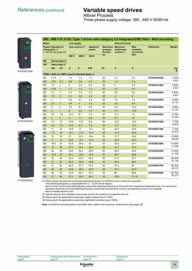
Variable speed drivesAltivar ProcessThree-phase supply voltage: 380...480 V 50/60 Hz
ATV630D15N4
ATV630D30N4
ATV630D55N4
380...480 V IP 21/UL Type 1 drives with category C2 integrated EMC filter - Wall mountingMotor Line supply Altivar ProcessPower indicated on rating plate (1)(> 45 kW, see page 20)
Line current (2) Apparent power
Maximum prospec-tive line Isc
Maximum continuous current (1)
Max. transient current for 60 s
Reference Weight
380 V 480 V 380 V
ND: Normal duty (3)HD: Heavy duty (4)
kW HP A A kVA kA A A kg/lb
THDI y 44% at 100% load in Normal duty (3)ND 0.75 1 1.5 1.3 1.1 50 2.2 2.4 ATV630U07N4 4.500/
9.921HD 0.37 0.5 0.9 0.8 0.7 50 1.5 2.3ND 1.5 2 3 2.6 2.2 50 4 4.4 ATV630U15N4 4.500/
9.921HD 0.75 1 1.7 1.5 1.2 50 2.2 3.3ND 2.2 3 4.3 3.8 3.2 50 5.6 6.2 ATV630U22N4 4.500/
9.921HD 1.5 2 3.1 2.9 2.4 50 4 6ND 3 – 5.8 5.1 4.2 50 7.2 7.9 ATV630U30N4 4.600/
10.141HD 2.2 3 4.5 4 3.3 50 5.6 8.4ND 4 5 7.6 6.7 5.6 50 9.3 10.2 ATV630U40N4 4.600/
10.141HD 3 – 6 5.4 4.5 50 7.2 10.8ND 5.5 7.5 10.4 9.1 7.6 50 12.7 14 ATV630U55N4 4.700/
10.362HD 4 5 8 7.2 6.0 50 9.3 14ND 7.5 10 13.8 11.9 9.9 50 16.5 18.2 ATV630U75N4 7.700/
16.976HD 5.5 7.5 10.5 9.2 7.6 50 12.7 19.1ND 11 15 19.8 17 14.1 50 23.5 25.9 ATV630D11N4 7.700/
16.976HD 7.5 10 14.1 12.5 10.4 50 16.5 24.8ND 15 20 27 23.3 19.4 50 31.7 34.9 ATV630D15N4 13.600/
29.983HD 11 15 20.6 18.1 15.0 50 23.5 35.3ND 18.5 25 33.4 28.9 24 50 39.2 43.1 ATV630D18N4 14.200/
31.306HD 15 20 27.7 24.4 20.3 50 31.7 47.6ND 22 30 39.6 34.4 28.6 50 46.3 50.9 ATV630D22N4 14.300/
31.526HD 18.5 25 34.1 29.9 24.9 50 39.2 58.8ND 30 40 53.3 45.9 38.2 50 61.5 67.7 ATV630D30N4 28.000/
61.729HD 22 30 40.5 35.8 29.8 50 46.3 69.5ND 37 50 66.2 57.3 47.6 50 74.5 82 ATV630D37N4 28.200/
62.170HD 30 40 54.8 48.3 40.2 50 61.5 92.3ND 45 60 79.8 69.1 57.4 50 88 96.8 ATV630D45N4 28.700/
63.273HD 37 50 67.1 59.0 49.1 50 74.5 111.8
(1) These values are given for a nominal switching frequency of 4 kHz for use in continuous operation. The switching frequency is adjustable from 2…12 kHz for all ratings. Above 4 kHz, the drive will automatically reduce the switching frequency in the event of an excessive temperature rise. For continuous operation above the nominal switching frequency, derate the nominal drive current, see derating curves on our website www.schneider-electric.com.
(2) Typical value for the indicated motor power and for the maximum prospective line Isc.(3) Values given for applications requiring a slight overload (up to 110%).(4) Values given for applications requiring a significant overload (up to 150%).
Note: Consult the summary tables of possible drive, option and accessory combinations (see page 28).

20
References (continued) Variable speed drivesAltivar ProcessThree-phase supply voltage: 380...480 V, 380...440 V 50/60 Hz
ATV630D55N4
380...480 V IP 21/UL Type 1 drives with category C3 integrated EMC filter - Wall mounting Motor Line supply Altivar ProcessPower indicated on rating plate (1)(< 55 kW, see page 19)
Line current (2) Apparent power
Maximum prospec-tive line Isc
Maximum continuous current (1)
Max. transient current for 60 s
Reference Weight
380 V 480 V 380 V
ND: Normal duty (3)HD: Heavy duty (4)
kW HP A A kVA kA A A kg/lb
THDI y 44% at 100% load in Normal duty (3)ND 55 75 97.2 84.2 70 50 106 116.6 ATV630D55N4 56.500/
124.561HD 45 60 81.4 71.8 59.7 50 88 132ND 75 100 131.3 112.7 93.7 50 145 159.5 ATV630D75N4 58.000/
127.868HD 55 75 98.9 86.9 72.2 50 106 159ND 90 125 156.2 135.8 112.9 50 173 190.3 ATV630D90N4 58.500/
128.970HD 75 100 134.3 118.1 98.2 50 145 217.5ND 110 150 201 165 121.8 50 211 232.1 ATV630C11N4 (5) 85.000/
187.393HD 90 125 170 143 102.6 50 173 259.5ND 132 200 237 213 161.4 50 250 275 ATV630C13N4 (5) 85.000/
187.393HD 110 150 201 165 121.8 50 211 270ND 160 250 284 262 201.3 50 302 332.2 ATV630C16N4 (5) 85.000/
187.393HD 132 200 237 213 161.4 50 250 360
380...440 V IP 21 drives with category C3 integrated EMC filter - Floor standing (6)Motor Line supply Altivar ProcessPower indicated on rating plate (1)
Line current (2) Apparent power
Maximum prospec-tive line Isc
Maximum continuous current (1)
Max. transient current for 60 s
Reference Weight
380 V 400 V 380 V
ND: Normal duty (3)HD: Heavy duty (4)
kW HP A A kVA kA A A kg/lb
THDI y 44% at 100% load in Normal duty (3)ND 110 – 207 195 135 50 211 232 ATV630C11N4F 300.000/
661.386HD 90 – 174 164 113 50 173 259ND 132 – 250 232 161 50 250 275 ATV630C13N4F 300.000/
661.386HD 110 – 207 197 136 50 211 316ND 160 – 291 277 192 50 302 332 ATV630C16N4F 300.000/
661.386HD 132 – 244 232 161 50 250 375ND 200 – 369 349 242 50 370 407 ATV630C20N4F 400.000/
881.848HD 160 – 302 286 198 50 302 453ND 250 – 453 432 299 50 477 524 ATV630C25N4F 400.000/
881.848HD 200 – 369 353 244 50 370 555ND 315 – 566 538 373 50 590 649 ATV630C31N4F 400.000/
881.848HD 250 – 453 432 299 50 477 715
(1) These values are given for a nominal switching frequency of 2.5 kHz for use in continuous operation. The switching frequency is adjustable from 2…8 kHz for all ratings. Above 2.5 kHz, the drive will automatically reduce the switching frequency in the event of an excessive temperature rise. For continuous operation above the nominal switching frequency, derate the nominal drive current, see derating curves on our website www.schneider-electric.com.
(2) Typical value for the indicated motor power and for the maximum prospective line Isc.(3) Values given for applications requiring a slight overload (up to 110%).(4) Values given for applications requiring a significant overload (up to 150%).(5) Product supplied as IP 00 for mounting in an enclosure. For IP 21/UL Type 1 wall mounting, order separately the kit for IP 21/UL Type 1
conformity VW3A9704.(6) Integrated motor chokes allowing a shielded motor cable length up to 300 m/984 ft in category C3 and an unshielded cable length up to
450 m/1476 ft in category C4.
Note: Consult the summary tables of possible drive, option and accessory combinations (see page 28).
ATV630C16N4F

21
References (continued) Variable speed drivesAltivar ProcessThree-phase supply voltage: 380...480 V 50/60 Hz
ATV650D15N4
ATV650D30N4
ATV650D55N4
380...480 V IP 55 drives with category C2 or C3 integrated EMC filter - Wall mounting (1)
Motor Line supply Altivar ProcessPower indicated on rating plate (2)
Line current (3) Apparent power
Maximum prospec-tive line Isc
Maximum continuous current (2)
Max. transient current for 60 s
Reference(6)
Weight
380 V 480 V 380 VND: Normal duty (4)HD: Heavy duty (5)
kW HP A A kVA kA A A kg/lb
THDI y 44% at 100% load in Normal duty (4)ND 0.75 1 1.5 1.3 1.1 50 2.2 2.4 ATV650U07N4 10.500/
23.149HD 0.37 0.5 0.9 0.8 0.7 50 1.5 2.3ND 1.5 2 3 2.6 2.2 50 4 4.4 ATV650U15N4 10.500/
23.149HD 0.75 1 1.7 1.5 1.2 50 2.2 3.3ND 2.2 3 4.3 3.8 3.2 50 5.6 6.2 ATV650U22N4 10.500/
23.149HD 1.5 2 3.1 2.9 2.4 50 4 6ND 3 – 5.8 5.1 4.2 50 7.2 7.9 ATV650U30N4 10.600/
23.369HD 2.2 3 4.5 4 3.3 50 5.6 8.4ND 4 5 7.6 6.7 5.6 50 9.3 10.2 ATV650U40N4 10.600/
23.369HD 3 – 6 5.4 4.5 50 7.2 10.8ND 5.5 7.5 10.4 9.1 7.6 50 12.7 14 ATV650U55N4 10.700/
23.589HD 4 5 8 7.2 6.0 50 9.3 14ND 7.5 10 13.8 11.9 9.9 50 16.5 18.2 ATV650U75N4 13.700/
30.203HD 5.5 7.5 10.5 9.2 7.6 50 12.7 19.1ND 11 15 19.8 17 14.1 50 23.5 25.9 ATV650D11N4 13.700/
30.203HD 7.5 10 14.1 12.5 10.4 50 16.5 24.8ND 15 20 27 23.3 19.4 50 31.7 34.9 ATV650D15N4 19.600/
43.211HD 11 15 20.6 18.1 15 50 23.5 35.3ND 18.5 25 33.4 28.9 24 50 39.2 43.1 ATV650D18N4 20.600/
45.415HD 15 20 27.7 24.4 20.3 50 31.7 47.6ND 22 30 39.6 34.4 28.6 50 46.3 50.9 ATV650D22N4 20.600/
45.415HD 18.5 25 34.1 29.9 24.9 50 39.2 58.8ND 30 40 53.3 45.9 38.2 50 61.5 67.7 ATV650D30N4 50.000/
110.231HD 22 30 40.5 35.8 29.8 50 46.3 69.5ND 37 50 66.2 57.3 47.6 50 74.5 82 ATV650D37N4 50.000/
110.231HD 30 40 54.8 48.3 40.2 50 61.5 92.3ND 45 60 79.8 69.1 57.4 50 88 96.8 ATV650D45N4 50.000/
110.231HD 37 50 67.1 59 49.1 50 74.5 111.8ND 55 75 97.2 84.2 70 50 106 116.6 ATV650D55N4 87.000/
191.802HD 45 60 81.4 71.8 59.7 50 88 152ND 75 100 131.3 112.7 93.7 50 145 159.5 ATV650D75N4 87.000/
191.802HD 55 75 98.9 86.9 72.2 50 106 159ND 90 125 156.2 135.8 112.9 50 173 190.3 ATV650D90N4 87.000/
191.802HD 75 100 134.3 118.1 98.2 50 145 217.5
(1) Category C2 EMC filter for ATV650U07N4 . . .D45N4. Category C3 EMC filter above ATV650D45N4.(2) These values are given for a nominal switching frequency of 4 kHz adjustable from 2...12 kHz up to ATV650D45N4 or 2.5 kHz
adjustable from 2…8 kHz for ATV650D55N4 . . .D90N4, for use in continuous operation.Above 2.5 or 4 kHz (depending on the rating), the drive will automatically reduce the switching frequency in the event of an excessive temperature rise. For continuous operation above the nominal switching frequency, derate the nominal drive current, see derating curves on our website www.schneider-electric.com.
(3) Typical value for the indicated motor power and for the maximum prospective line Isc.(4) Values given for applications requiring a slight overload (up to 110%).(5) Values given for applications requiring a significant overload (up to 150%).(6) Supplied with cable gland.
Note: Consult the summary tables of possible drive, option and accessory combinations (see page 28).

24
Presentation, references
Variable speed drivesAltivar ProcessOption: Configuration and runtime tools
Graphic display terminal (supplied with the drive)This terminal can be:
b Connected and mounted on the front of the drive b Connected and mounted on an enclosure door using a remote mounting
accessory b Connected to a PC to exchange files via a Mini USB/USB connection (1) b Connected to several drives in multidrop mode (see page 25)
This terminal is used to: b Control, adjust, and configure the drive b Display current values (motor, I/O, and process data) b Display graphic dashboards such as the energy consumption monitoring
dashboard b Store and download configurations (several configuration files can be stored in
the 16 MB memory) b Duplicate the configuration of one powered-up drive on another powered-up
drive b Copy configurations from a PC or drive and duplicate them on another drive (the
drives must be powered on for the duration of the duplication operations)Other characteristics:
b 24 integrated languages (complete alphabets) covering the majority of countries around the world (other languages can be added; please consult our website www.schneider-electric.com)
b 2-color backlit display (white and red); if an error is detected, the red backlight is activated automatically (function can be disabled)
b Operating range: -15…50 °C/+5…122 °F b Degree of protection: IP 65 b Trend curves: Graphic display of changes over time in monitoring variables,
energy data, and process data b Graphic display of a pump’s dynamic operation in relation to its optimum
operation b Embedded dynamic QR codes for contextual, instantaneous access to online
help (diagnostics and settings, etc.) using a smartphone or tablet b Real-time clock with 10-year backup battery providing data acquisition and event
timestamping functions even when the drive is stoppedDescription
Display: b 8 lines, 240 x 160 pixels b Displays bar charts, gauges, and trend charts b 4 function keys to facilitate navigation and provide contextual links for enabling
functions b “STOP/RESET” button: Local control of motor stop command/clearing detected
faults b “RUN” button: Local control of motor run command b Navigation buttons: v OK button: Saves the current value (ENT) v Turn ±: Increases or decreases the value, goes to the next or previous line v “ESC” button: Aborts a value, parameter, or menu to return to the previous
selection v Home: Root menu v Information (i): Contextual help
ReferencesDescription Reference Weight
kg/ lb
Graphic display terminal: VW3A1111 0.200/ 0.441
Communication accessoryDescription Reference Weight
kg/ lb
IP 20 WiFi dongleremote mounting of the Ethernet port for connectionof WiFi equipment (PC, tablet, smartphone, etc.) powered by internal rechargeable battery
TCSEGWB13FA0 0.350/ 0.772
(1) Graphic display terminal used only as a handheld terminal.
Graphic display terminal(example shows dynamic pump operation in relation to its optimum operation)
Detected fault: The screen’s red backlight is activated automatically
Embedded dynamic QR codes for contextual, instantaneous access to online help
Scanning the QR code from a smartphone or tablet
Instant access to online help
Presentation:page 8
Variable speed drives:page 18
Combinations:page 28
Communication buses and networks: page 34
Dimensions:page 70

25
Presentation, references
Variable speed drivesAltivar ProcessOption: Configuration and runtime tools
Accessories for graphic display terminal b Remote mounting kit for mounting on enclosure door with IP 65 degree of protection
as standardThe kit comprises:- Tightening tool (also sold separately under the reference ZB5AZ905)1 Cover plate to maintain IP 65 protection when there is no terminal connected2 Mounting plate3 RJ45 port for the graphic display terminal4 Seal5 Fixing nut6 Anti-rotation pin7 RJ45 port for connecting the remote-mounting cordset (10 m/32.81 ft maximum)
Cordsets should be ordered separately depending on the length required8 Grounding connectorDrilling a hole with a standard Ø 22 tool, as used for a pushbutton, allows the unit to be mounted without needing a cut-out in the enclosure (Ø 22.5 mm/Ø 0.89 in. drill hole).ReferencesDescription Length
m/ ft
IP Reference Weightkg/
lbRemote mounting kitOrder with remote-mounting cordsetVW3A1104Rppp
– 65 VW3A1112 –
Tightening toolfor remote mounting kit
– – ZB5AZ905 0.016/ 0.035
Remote-mounting cordsetequipped with 2RJ45 connectors
1/ 3.28
– VW3A1104R10 0.050/0.110
3/ 9.84
– VW3A1104R30 0.150/ 0.331
5/ 16.40
– VW3A1104R50 0.250/ 0.551
10/ 32.81
– VW3A1104R100 0.500/ 1.102
USB/Mini B USB cablefor connecting the display terminal to a PC
– – TCSXCNAMUM3P –
IP 65 remote mounting kit for Ethernet port (1)Ø 22 RJ45 female/female adapter with seal
– 65 VW3A1115 0.200/ 0.441
Multidrop connection accessoriesThese accessories are used to connect a graphic display terminal to several drives via a multidrop link. This multidrop connection uses the RJ45 terminal port on the front of the drive.Connection accessoriesDescription Sold in
lots ofUnit reference
Weightkg/
lbModbus splitter box10 RJ45 connectors and 1 screw terminal block
– LU9GC3 0.500/ 1.102
Modbus T-junction boxes
With 0.3 m/0.98 ft integrated cable
– VW3A8306TF03 0.190/ 0.419
With 1 m/3.28 ft integrated cable
– VW3A8306TF10 0.210/ 0.463
Modbus line terminator
ForRJ45 connector
R = 120 ΩC = 1 nf
2 VW3A8306RC 0.010/ 0.022
Cordsets (equipped with 2 RJ45 connectors)Used for Length
m/ft
Reference Weightkg/
lbSerial link 0.3/
0.98VW3A8306R03 0.025/
0.0551/ 3.28
VW3A8306R10 0.060/ 0.132
3/ 9.84
VW3A8306R30 0.130/ 0.287
(1) Used to connect a remote PC to the RJ45 port on an IP 21 drive mounted in an enclosure or on a wall. Drill hole with a standard Ø 22 tool, as used for a pushbutton.(Requires a remote-mounting cordset VW3A1104Rp0p equipped with 2 RJ45 connectors).
Remote mounting kit for mounting graphic display terminal on enclosure door (front panel)
1
3
2
4
Remote mounting kit for graphic display terminal (rear panel)
1
45
67
2
8