general notes - florida department of transportation · sketch showing frame seat and throat recess...
TRANSCRIPT

10/16/2017
8:4
0:5
3
AM
RE
VISIO
N DESCRIPTION:
REVISION
LAST
ofSTANDARD PLANS
FY 2018-19 SHEETINDEX
11/01/17CURB INLET TOPS TYPES 5 AND 6
425-021 1 5
Inlet Or Riser
For C-I-P Inlets
6" Ø Concrete Post
� Inlet (Type 6 Symmetrical about �)
Curb Control Line)
9" (10" Below Top Of
" Radius41" Chamfer Or 14
3
Outline of Grate
Bars 4H
2 ~ Bars 4J
Bars 4F @ 12" Sp.
6"
Symmetrical About �)
� Inlet (Type 6
Corner Fillets (See Note 6)
Bars 4K (For Fillets Only)
Bar 4E
Bar 4L
2 ~ Bars 4J
Bars 4S
Bars 4ABars 4B (Vert. Face, Field Bend)
For C-I-P Inlets
6" Ø Concrete Post
6"
(Tied to Bars 4A)
Bars 4E @ 5" Bottom
1'-
6"
2'-
0"
1'-
0"
12"
12"
Control Line
Top Of Curb
Symmetrical About �)
� Inlet (Type 6
� Inlet
Bars 4B (Top) @ 6" Sp.
Bars 4D (Bottom) @ 6" Sp.
Face, Field Bend)
Bars 4B (Vert.
Bars 4A & 4C @ 5" Sp.
Transition
Type E Curb
Transition
Type F Curb
� Inlet
Sta./Offset Location
Center Of Box
GENERAL NOTES
SKETCH SHOWING FRAME SEAT AND THROAT RECESS
SECTION BB
TOP VIEW
INLET TYPE 5 (Curb Inlet Type 6 Symmetrical With Left Half)
SECTION AA (At � Inlet)
BB
Gutter Transition
3'-0"2'-6"8'-0"
Gutter Transition
3'-0"
4"
(Nose)
9"
6"
6"
9"
Bars 4A ~ 24 sp. @ 5" = 10'-0"
5'-9"
3" 6"
6"6"C-I-P Inlets
Precast Inlets
Bars 4S @ 8"
3'-6"
4'-9"
6"
"214
"2
110
"2
11
"214
9"
"213 "2
12
3" Grate Recess
(Typ.)
12"
A
C
C D
D
E
E
Q Q
F
F G
G H
C
C
H
A
Gutter Transition
3'-0"
(See Note 8)
Type E Or F Curb
Gutter Transition
3'-0"
Note 8)
Curb (See
Type E Or F 4'-9"
Inlet Throat Transition
5'-9"
As Curb & Gutter
To Be Paid For
As Curb & Gutter
To Be Paid For
3"
Limits Of Inlet Construction (See Note 13)
InletTy
pe 5
(Type 6 Symmetrical About �)
Type 5 & 6 Inlet
Inlet to be paid for under the contract unit price for Inlets (Curb) (Type _), Each.13.
grouted in accordance with the grouting detail shown on Sheet 5, in lieu of tack welding.
steel frame or the the galvanized steel grate and frame must be used. Grates are to be
When Alternate "G" grate is specified in the plans either the cast iron grate and galvanized 12.
Either cast iron grates or steel grates may be used.11.
All steel used for frame and grate shall meet the requirements of ASTM A36/A36M.10.
See Index 425-001 for supplemental details.9.
curb over the gutter transition length to match the face of the inlet (Type F).
Locate inlet outside of pedestrian crosswalks. For Type E curb, transition the shape of the
These inlet tops are designed for use with standard curb and gutter Type E and Type F. 8.
openings.
Type J bottoms with 3'-6" square (Type B), 3'-6" or 4' round (Type A) risers or top slab
For inlet bottoms see Index 425-010. Inlet tops are to be used with Type P bottoms, or 7.
fillets flush with drain throat bottom and match slope.
conjunction with circular inlet bottoms or skewed rectangular inlet boxes. Finish top of
Corner fillets are required at inlet opening for precast units or C-I-P units used in 6.
Section 449 of the Specifications.
II concrete for precast units, manufactured in plants which meet the requirements of
Concrete meeting the requirements of ASTM C478 (4,000 psi) may be used in lieu of Class 5.
drawing approval shall be directed to the State Drainage Engineer.
the dimensions shown or in accordance with approved shop drawing's. Request for shop
Inlet tops shall be either cast-in-place or precast concrete. Precast units shall conform to 4.
see Sheet 4 for equivalent area Welded Wire Reinforcement details.
" minimum cover unless otherwise shown, 41All reinforcing steel to be Grade 60 bars with 13.
the inlet details accordingly. Bend steel when necessary.
For inlets constructed on a curve, refer to the plans to determine the radius, and modify 2.
and grade of the proposed sidewalk and/or border.
The finished grade and slope of the inlet tops are to conform with the finished cross slope 1.
10/16/2017
8:4
0:5
3
AM
RE
VISIO
N DESCRIPTION:
REVISION
LAST
ofSTANDARD PLANS
FY 2018-19 SHEETINDEX
11/01/17CURB INLET TOPS TYPES 5 AND 6
425-021 2 5
1'-
8"
"2
11'-
3
10"
"2
15
"831
to 2'-0" Max.)
Varies (1'-0" Min.
4" "2
14
Varie
sVarie
s
1'-6"
Maintain 1 Ɓ" CoverField Cut Bars To
5"
"2
110
1'-3"
4"
And ¾" Bottom Chamfer Or 1¼" Radius
Slope To Match Adjacent Curb With 2" Top Radius
"2110"2
111'-6"2'-0"
"214"2
17
"214
"2
14
1'-
8"
4"
"2
15
10"
4"
@ 6" (Top)
3 ~ Bars 4B
@ 6" (Bottom)
4 ~ Bars 4D"2
11
10"
Bars 4A @ 5" Sp.
Bars 4C @ 5" Sp.
@ 6"
Max.
3 ~ Bars 4
B
Bars 4E @ 5" Sp. Bars 4F @ 12" Sp. Bars 4J
Bars 4H In Corners
@ 8"
Bars 4S
(Centered Below Opening)
1'-6" "211 "2
110
"2
14
4"
"211
"214"2
17
"214
4"
4"
10"
@ 6" (Bottom)
4 ~ Bars 4D
@ 6" (Top)
3 ~ Bars 4B
@ 6"
Max.
3 ~ Bars 4
B
Thic
kness
Sla
b
3'-6"
4'-0"
"2
110
5"
1'-
8"
2'-0"
10"
¾" Chamfer
And ¾" Bottom Chamfer Or 1¼" Radius
Slope To Match Adjacent Curb With 2" Top Radius
Fillet
Bar 4K Diag.
(See Note 6, Sheet 1)
12" Corner Fillet
Bars 4S @ 8"
Note 7, Sheet 1)
(Type Varies, See
Inlet Bottom Or Riser
Top Of Pipe
Thickness Plus 3"
Present, Top Slab
9" Min. Or If Top Slab
These Limits
Constructed Within
Pipe Shall Not Be
Bars 4H In Corners
Bars 4C @ 5" Sp.
Bars 4A @ 5" Sp.
1'-
8"
"2
11'-
3
3"
1'-0" 1'-6"
9"
10"
Control Line
Top Of Curb
3" Radius
Optional
"2
14
Elev.
Depression
Theoretical
10"
1'-
8"
"2
110
5"
"2
14
"2110"2
111'-6"2'-0"
"211
9"
"4
38
5"
±
4"
4"
"214
"217 "2
14
@ 6" (Bottom)
4 ~ Bars 4D
@ 6" (Top)
3 ~ Bars 4B
@ 6"
Max.
3 ~ Bars 4
B
1 ~ Bar 4E Bars 4F @ 12" Sp. Bars 4J Bars 4S @ 8" Bars 4H In Corners
As Shown)
Bar 4L (Placed
Bars 4C @ 5" Sp.
Bars 4A @ 5" Sp.
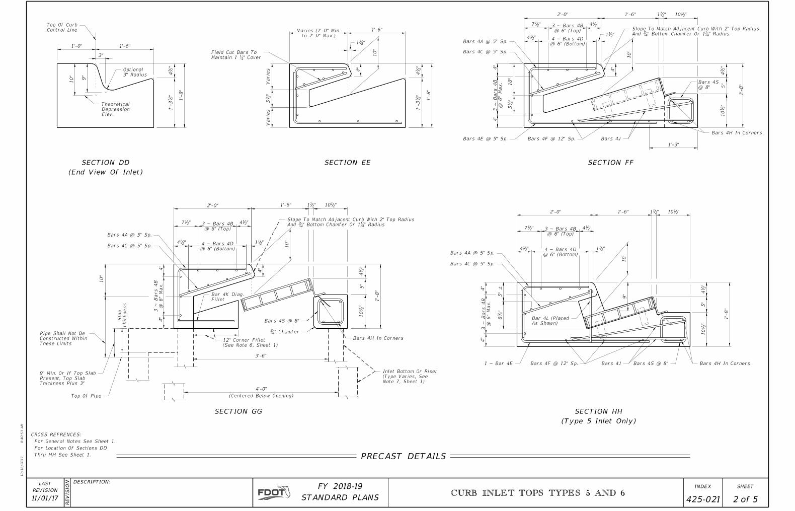
PRECAST DETAILS
SECTION EE SECTION FF
SECTION GG
(Type 5 Inlet Only)
SECTION HH
Thru HH See Sheet 1.
For Location Of Sections DD
For General Notes See Sheet 1.
CROSS REFRENCES:
(End View Of Inlet)
SECTION DD

10/16/2017
8:4
0:5
4
AM
RE
VISIO
N DESCRIPTION:
REVISION
LAST
ofSTANDARD PLANS
FY 2018-19 SHEETINDEX
11/01/17CURB INLET TOPS TYPES 5 AND 6
425-021 3 5
to 2'-0" Max.)
Varies (1'-0" Min.
2¼" Cover (Above Soil)
2¼" Cover (Above Soil)
to 2'-0" Max.)
Varies (1'-0" Min.
Spacing Bars 4B
Spacing Bars 4B
5"
±
(Centered Below Opening)
Varie
sVarie
s
1'-6"
6"
6" Type F Curb6" to 9" Type E Curb
9"
10"
1'-6"
3"
1'-0"
1'-
9"
"2
11'-
4
9"
10"
1'-6"
3"
1'-0"
1'-
9"
"2
17
1'-6"
"2
11'-
4
1'-
9"
10"
"831
"2
15
"2
17
Maintain 1¼" Cover
Field Cut Bars To
"2
15
"8
39
10"
"831
1'-6"
7"
5"
"2
110
7"
"4
38
9"
10"
"2
110
5"
3'-6"
4'-0"
5"
7"
1'-
8"
"2
14
5"
"2
110
10"
4"
5"
4"
10"
4"
"2
15
"214
"217
@ 6" (Bottom)
4 ~ Bars 4D "211
@ 6" (Top)
3 ~ Bars 4B "214
2'-0" 1'-6" "211 "2
110
3'-0"
1'-3"
1'-6"
And ¾" Bottom Chamfer Or 1¼" Radius
Slope To match Adjacent Curb With 2" Top Radius
Bars 4F @ 12" Sp.
Joint
Const.
Bars 4A @ 5" Sp.
Bars 4C @ 5" Sp.
Bars 4E @ 5" Sp.
Concrete)
1¼" Cover (Above
Bars 4J
Bars 4S @ 8"
Bars 4H In Corners
1'-
8"
"2
14
"2110"2
111'-6"2'-0"
"211
"214"2
17
"214
4"
5"
4"
Bars 4A @ 5" Sp.
Bars 4C @ 5" Sp.
As Shown)
Bar 4L (Placed
Joint
Const.
@ 6" (Top)
3 ~ Bars 4B
@ 6" (Bottom)
4 ~ Bars 4D
1 ~ Bar 4E Bars 4F @ 12" Sp. Bars 4J Bars 4S @ 8" Bars 4H In CornersNote 7, Sheet 1)
(Type Varies, See
Inlet Bottom Or Riser
Bars 4H In Corners
1'-
8"
"2
14
"2110"2
111'-6"
10"
4"
2'-0"
"214
"211"2
14
"217
4"
4"
10"
@ 6" (Top)
3 ~ Bars 4B
@ 6" (Bottom)
4 ~ Bars 4D
And ¾" Bottom Chamfer Or 1¼" Radius
Slope To match Adjacent Curb With 2" Top Radius
Bars 4A @ 5" Sp.
Bars 4C @ 5" Sp.
Bars 4L @ 5" Sp.
Joint
Const.
Fillet
Bar 4K Diag.
Thic
kness
Sla
b
These Limits
Constructed Within
Pipe Shall Not Be
Thickness Plus 3"
Present, Top Slab
9" Min. Or If Top Slab
Top Of Pipe
(See Note 6, Sheet 1)
12" Corner Fillet
Bars 4S @ 8"
¾" Chamfer
Joint
Const.
"2
14
4"
Varie
s
"2
14
4"
Const. Joint
Maintain 1¼" Cover
Field Cut Bars To
(12" to 1'-3") Type F Curb
(11" to 1'-3") Type E Curb
Varies
Depression Elev.
Theoretical
3" Radius
Optional
Top Of Curb Control Line
"2
14
Top Of Curb Control Line
3" Radius
Optional
Depression Elev.
Theoretical
"2
14
"2
14
Varie
s
Varie
s
SECTION GG
SECTION FF
SECTION EE (OPTION A)
(End View Of Inlet)
SECTION DD (OPTION A)
(End View Of Inlet)
SECTION DD (OPTION B)
Type F Shown, Type E Similar)
(Gutter Transition
SECTION CC
SECTION EE (OPTION B)
CAST-IN-PLACE DETAILS
SECTION HH (Type 5 Inlet Only)
For Location Of Sections CC Thru HH See Sheet 1.
For General Notes See Sheet 1.
CROSS REFRENCES:

10/16/2017
8:4
0:5
4
AM
RE
VISIO
N DESCRIPTION:
REVISION
LAST
ofSTANDARD PLANS
FY 2018-19 SHEETINDEX
11/01/17CURB INLET TOPS TYPES 5 AND 6
425-021 4 5
8"
2 Sp. @ 6"
24 Sp. @
5"
(Type 5)
37 Sp. @ 5"(Type 6)
"215'-7
"214'-11
"214'-7
"21
5'-7
(1'-0" Max.)To Maintain CoverField Cut As Required
C-I-P
Precast
"2
14
10'-3" (Min.)
To Allow Fi
eld Bendin
g Of Mat
Cut Horizo
ntal Bars
As Shown
@ 5"
37 Sp.
(Min.)
15'-9"
(Piece No. 1 & 3)
Cover"411
1'-
4"
1'-9"
"4
11
"432
4"
1"
1'-11"
"212
"41
4
"414
(Typ.)D17.2 or W18.5
"214
1'-
4"
3'-3"
(1'-0" Max.)To Maintain CoverField Cut As Required
8"
8"
1'-9"
1'-
4"
3'-3"
2" 1'-1"
(Typ.)
D17.2 Or W18.5
1'-
4"
"21
3
Outline Of Top Slab
4" 2"
� For Type 6WWR Symmetrical About
As Required To Maintain Cover
Cut Dotted Portion Of Mat
As Required To Maintain Cover
Cut Dotted Portion Of Mat
As Required To Maintain Cover
Cut Dotted Portion Of Mat
Throat Bottom
Outline Of Inlet
Outline Of Top Slab End Of Type 6 Top
Bars In Vertical Face
Field Bend Horizontal
About � For Type 6WWR Symmetrical
4"
6 Top
End Of Type
" Cover411
Piece No. 1
Piece No. 3
Piece No. 2
Conventional Reinf. Bar 4F
4H & 4S
Reinf. For Bar 4J,
Provide Conventional
(One Required)
Reinf. Bar 4F
Conventional
4" (Typ.)
2 Sp. @ 12"
13 Sp. @
5"
5'-7" (Min
.)
24 Sp. @ 5" (Type 5)
" Cover
41
1"
Cover
41
1
2 S
p.
@ 6"
D17.2 or W18.5 (Typ.)
3 Sp.
@ 6"
CONVENTIONAL REINFORCING STEEL BENDING DIAGRAMS
BILL OF REINFORCING STEEL
4
10'-3"
3'-1"
6'-0"
25
B 4 6
C 4 11" to 1'-11"25
D 4 10'-3"4
E 4 16
F 4 3
2'-3"
H 4 4'-6"4
J 4 3'-0"4
K (Fillet) 4 2
L (C-I-P) 4 1'-4"10
S 4 3'-2"7
3'-1"38
6
38
15'-9"4
30
6
4'-6"4
3'-0"4
2
1'-4"9
15'-9"
6'-0"
2'-3"
3'-2"7
4 1'-4"1 ---0
4 25 38A (C-I-P)
11" to 1'-11"
A (Precast)
TYPE 6 INLET
LENGTHNO.LENGTH
TYPE 5 INLET
NO.
SIZEMARK
ALTERNATE REINFORCING STEEL DETAILS FOR WELDED WIRE REINFORCEMENT (WWR)
PIECE NO. 1
WELDED WIRE REINFORCEMENT
PIECE NO. 2
WELDED WIRE REINFORCEMENT
PIECE NO. 3
WELDED WIRE REINFORCEMENT
WELDED WIRE REINFORCEMENT
TYPICAL SECTION SHOWING
BAR 4E
BAR 4A
BAR 4S
L (Precast)
"212'-1 "2
12'-1
"214'-11
WIRE REINFORCEMENT PIECE NO. 3
PLACEMENT SCHEMATIC FOR WELDED
WIRE REINFORCEMENT PIECE NO. 2
PLACEMENT SCHEMATIC FOR WELDED
WIRE REINFORCEMENT PIECE NO. 1
PLACEMENT SCHEMATIC FOR WELDED
931.
requirements of Specification Section
Smooth or Deformed wire meeting the
Welded Wire Reinforcement consists of 3.
a single bar.
Bars 4A and 4E may be combined into 2.
diagrams are out to out.
All bar dimensions in the bending 1.
REINFORCING STEEL NOTES:

10/16/2017
8:4
0:5
5
AM
RE
VISIO
N DESCRIPTION:
REVISION
LAST
ofSTANDARD PLANS
FY 2018-19 SHEETINDEX
11/01/17CURB INLET TOPS TYPES 5 AND 6
425-021 5 5
" o. to o. Of Grate211'-9
"41¢
83x2
1�6x3
Grommet
Grout
Epoxy-Sand
9"
"2
11
Anchor
"41¢
" o. to o. Of Grate211'-9
83x2
1�6x3
Grommet
9"
4"
Grout
Epoxy-Sand
Side
Grout Each
Epoxy-Sand
10°
60°
" x 2"163Bar
"41¢
Anchor
Nonskid Floor Plate
" Pickholes43
(See Detail)
Anchor
Cover
83�3x2x
83x2
1�6x3
(See Detail)
Anchor
2"
Side
Grout Each
Epoxy-Sand
83x2
1�6x3
3' -11" o. to o. Of Grate
" o. to o. Of Frame414'-0
"41
"83
83�4x3x
4"
"41 3' -11" o. to o. Of Grate
" o. to o. Of Frame414'-0
"4
16 10"
"41
"41
3'-11"
"21
4"
1"
1"
"2
1
"2
11'-
9
3""21
"4
3 "4
1
"851
"16
5
2""1674
2"
"2
11
"1611"2
12
"8
51
"1611
"21
"2
11
3'-11"
"2
11'-
9
"4
3
"16
11
"8
31
"2
11
3"
"4
11
"41
"41
10""4
16
"212
GROUTING DETAILS
CAST IRON GRATE
TOP VIEW
SECTION XX
(Typ.)
2 @ 8
SECTION YY
XX
Y
Y
4 S
paces
@ 5"
" 81
SECTION GG
STEEL GRATE
TOP VIEW
SECTION MM
STEEL GRATE
M
M
S
S
RR
SECTION RR
TOP VIEWSECTION SSSECTION GGSECTION NN
CAST IRON GRATE
TOP VIEW
N
N
"81
See Sheet 1.
For Location Of Section GG and QQ
CROSS REFERENCES:
FRAME DETAIL
TOP VIEW
Q Q
"81
SECTION QQ
"81
SECTION QQ
163
163
163
163
ANCHOR DETAIL