general information - motorkariimg.motorkari.cz/upload/files/manualy/538_954_01_general...general...
TRANSCRIPT

I I GENERAL INFORMATION SERVICE RULES 1-1 LUBRICATION & SEAL POINTS 1-19
MODEL I DENT1 FlCATl ON 1-1 CABLE & HARNESS ROUTING 1-23
SPECIFICATIONS 1-3 EMISSION CONTROL SYSTEMS 1-37
TORQUE VALUES
TOOLS
1-12 EMISSION CONTROL INFORMATION LABELS 1-40
1-17
SERVICE RULES 1. Use genuine Honda or Honda-recommended parts and lubricants or their equivalents. Parts that do not meet Honda's
2. Use the special tools designed for this product to avoid damage and incorrect assembly. 3. Use only metric tools when servicing the motorcycle. Metric bolts, nuts and screws are not interchangeable with English
4. Install new gaskets, O-rings, cotter pins, and lock plates when reassembling. 5 . When tightening bolts or nuts, begin wi th the larger diameter or inner bolt first. Then tighten to the specified torque
diagonally in incremental steps unless a particular sequence is specified. 6. Clean parts in cleaning solvent upon disassembly. Lubricate any sliding surfaces before reassembly. 7. After reassembly, check all parts for proper installation and operation. 8. Route all electrical wires as shown on pages 1-23 through 1-36, Cable and Harness Routing.
design specifications may cause damage to the motorcycle.
fasteners.
MODEL IDENTIFICATION
1-1

GENERAL INFORMATION
(1) The frame serial number is stamped on the right side of the steering head.
(2) The engine serial number is stamped on the right side of the upper crankcase.
VEHICLE IDENTIFICATION NUMBER (VIN)
THROTTLE BODY ID~NTIFICATION NUMBER
(3) The Vehicle Identification Number (VIN) is located on left side of the main frame on the Safety Certification Labels.
(4) The throttle body identification number is stamped on the intake side of the throttle body as shown.
COLOR LABEL
(5) The color label is attached as shown. When ordering color-coded parts, always specify the designated color code.
1-2

GENERAL INFORMATION
SPECIFICATIONS GENERAL
ITEM
DIMENSIONS
FRAME
ENGINE
Overall length Overail width Overal I height Wheelbase Seat height Footpeg height Ground clearance Dry weight
49 states, Canada type: California type:
49 states, Canada type: California type:
Maximum weight capacity 49 states, California type: Canada type:
Curb weight
Frame type Front suspension Front wheel travel Rear suspension Rear wheel travel Rear damper Front tire size Rear tire size T i re brand
Bridgestone Michelin
Front brake Rear brake Caster angle Trail length Fuel tank capacity
Cylinder arrangement Bore and stroke Displacement Compression ratio Valve train Intake valve opens
closes Exhaust valve opens
closes Lubrication system Oil pump type Cooling system Air filtration Engine dry weight Firing order
at 1 mm (0.04 in) lift
SPECIFICATIONS
2,025 mm (79.7 in) 680 mm (26.8 in) 1,135 m m (44.7 in) 1,395 mm (54.9 in) 820 mm (32.3 in) 383 mm (15.1 in) 130 mm (5.1 in)
168 kg (370 Ibs) 170 kg (375 Ibs)
195 kg (430 Ibs) 197 kg (434 Ibs)
160 kg (353 Ibs) 164 kg (362 Ibs)
Diamond Inverted telescopic fork 110 mm (4.3 in) Swingarm 135 mm (5.3 in) Nitrogen gas fil led damper 120170 ZR17 M/C (58W) 190/50 ZR17 M/C (73W)
Front: BT012F RADIAL G /Rear: BT012R RADIAL G Front: Pilot SPORT E /Rear: Pilot SPORT E Hydraulic double disc brake wi th 4 pots caliper Hydraulic single disc brake with 1 pots caliper 23" 45' 97 mm (3.8 in) 18.0 liter (4.76 US gal, 3.96 Imp gal)
4 cylinders in-line, inclined 30" f rom vertical 75.0 x 54.0 m m (2.95 x 2.13 in) 954 cm3 (58.2 cu-in) 11.5: 1 Chain driven, DOHC 25' BTDC 38" ABDC 41" BBDC 22O ATDC Forced pressure and wet sump Trochoid Liquid cooled Paper element 61.2 kg (134.9 Ibs) 1 - 2 - 4 - 3
1-3

GENERAL INFORMATION ,-- GENERAL (Cont’d) ITEM
DRIVE TRAIN
I
Type Throttle bore
Clutch system Clutch operation system Transmission Primary reduction Final reduction Gear ratio 1 st
2nd 3rd 4th 5th 6th
Gearshift pattern
Ignition system Starting system Charging system Regulator/rectifier Lighting system
SPECIFICATIONS
PGM-FI (Programmed Fuel Injection) 42 mm (1.7 in)
Multi-plate, wet Cable operating Constant mesh, 6-speeds 1.520 (73/48) 2.687 (43/16) 2.692 (35/13) 1.933 (29/15) 1.600 (32/20) 1.400 (28/20) 1.285 (27/21) 1.190 (25/21) Left foot operated return system, 1 - N - 2 - 3 - 4 - 5 - 6
Computer-controlled digital transistorized with electric advance Electric starter motor Triple phase output alternator SCR shorted/triple phase, full wave rectification Battery

GENERAL INFORMATION
Engine oil capacity A t draining
At oil filter change
A t disassembly
Oil pump rotor
Unit: mm (in)
Tip clearance
Body clearance
Side clearance
STANDARD
ITEM
I SERVICE LIMIT
SPECIFICATIONS
3.5 liter (3.7 US qt, 3.1 Imp qt) I -
Throttle body identification number
3.7 liter (3.9 US qt, 3.3 Imp qt)
4.0 liter (4.2 US qt, 3.5 Imp qt)
__
-
Except California type GQ44C
California type GQ44B
Pro Honda GN4 or HP4 (without molybde- num additives) 4-stroke oil or equivalent motor oi l API service classification: SG or higher JASO T 903 standard: M A Viscositv: SAE 1 OW-40
Starter valve vacuum difference
Base throttle valve for synchronization
490 kPa (5.0 kgf/cm2, 71 psi) at 5,400 rr~m/(80"C/176"F)
20 mmHg
No.1
0.15 (0.006) I 0.20 (0.008)
Intake air temperature sensor resistance (at 20°C/68"F)
Enqine coolant temperature sensor resistance (at 20°C/68"F)
0.1 5 - 0.22 (0.006 - 0.009) 1 0.35 (0.014)
1 - 4 k R
2.3 - 2.6 kL2
~~
0.02 - 0.07 (0.001 - 0.003) 1 0.10 (0.004)
PAIR solenoid valve resistance (at 20"C/68"F)
Cam pulse generator peak voltage (at 20"C/68"F)
20 - 24 52
0.7 V minimum
Ignition pulse generator peak voltage (at 20"C/68"F)
Manifold absolute pressure at idle
Fuel pressure at idle ___
0.7 V minimum
150 - 250 mmHg
343 kPa (3.5 kqf/cm2, 50 psi)
Idle speed
Fuel pump f low (at 12 V)
Throttle nrip free play
188 cm3 (6.4 US oz, 6.6 Imp oz) minimum/lO seconds
1,200 f 100 rpm
2 - 6 mm (1/16 - 1/4 in)
Fuel injector resistance (at 2OoC/68"F) I 10.5 - 14.5 R I
1-5
GENERAL INFORMATION
ITEM SPECIFICATIONS
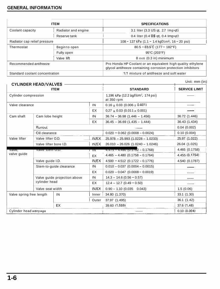
Coolant capacity
1 Valve lift
Recommended antifreeze
Standard coolant concentration
1 Radiator and engine I
8 rnm (0.3 in) minimum
Pro Honda HP Coolant or an equivalent high quality ethylene glycol antifreeze containing corrosion protection inhibitors
1:l mixture of antifreeze and soft water
1 Reserve tank i
Cylinder compression
Valve clearance 1 IN
3.1 liter (3.3 US qt, 2.7 Imp qt)
0.4 liter (0.4 US at, 0.4 Imp qt)
1,196 kPa (12.2 kgf/cm2, 174 psi) at 350 rpm
0.16 f 0.03 (0.006 f 0.001)
-
-
Radiator cap relief pressure I 108 - 137 kPa (1.1 - 1.4 kgf/cm2, 16 - 20 psi) i
Cam shaft Cam lobe height
Thermostat
EX 0.27 -c 0.03 (0.01 1 -r- 0.001) - IN 36.74 - 36.98 (1.446 - 1.456) 36.72 (1.446)
EX 36.45 - 36.69 (1.435 - 1.444) 36.43 (1.434)
Begin t o open
Fully open
Runout
80.5 - 83.5"C (177 - 182°F)
- 0.04 (0.002)
95°C (203°F)
Valve lifter Valve lifter O.D.
Valve lifter bore I.D.
Unit: mm (in) CYLINDER HEADNALVES I I
Valve, valve guide
I I SERVICE LIMIT ITEM STANDARD
Valve stem O.D.
Valve guide I.D.
Stem-to-guide clearance
Valve guide projection above cylinder head
Valve seat width
1 IN/EX 4.500 - 4.512 (0.1722 - 0.1776) 4.540 (0.1787)
IN 0.010 - 0.037 (0.0004 - 0.0015) - EX 0.020 - 0.047 (0.0008 - 0.0019) - IN 14.3 - 14.6 (0.56 - 0.57) - EX 12.4 - 12.7 (0.49 - 0.50) - lN/EX 1 0.90 - 1.10 (0.035 - 0.043) 1.5 (0.06)
I oil clearance 1 0.020 - 0.062 (0.0008 - 0.0024) 1 0.10 (0.004)
Valve spring free length IN
I IN/EX 1 25.978 - 25.993 (1.0228 - 1.0233) i 25.97 (1.022)
i IN/EX 1 26.010 - 26.026 (1.0240 - 1.0246) I 26.04 (1.025)
I IN 1 4.475 - 4.490 (0.1762 - 0.1768) I 4.465 (0.1758)
1 EX 1 4.465 - 4.480 (0.1758 - 0.1764) 1 4.455 (0.1754)
1 Inner I 34.80 (1.370) I 33.1 (1.30)
i Outer 1 37.97 (1.495) I 36.1 (1.42)
1 39.60 (1.559) I 37.6 (1.48)
Cylinder head warpaqe I 1 0.10 (0.004)
1-6
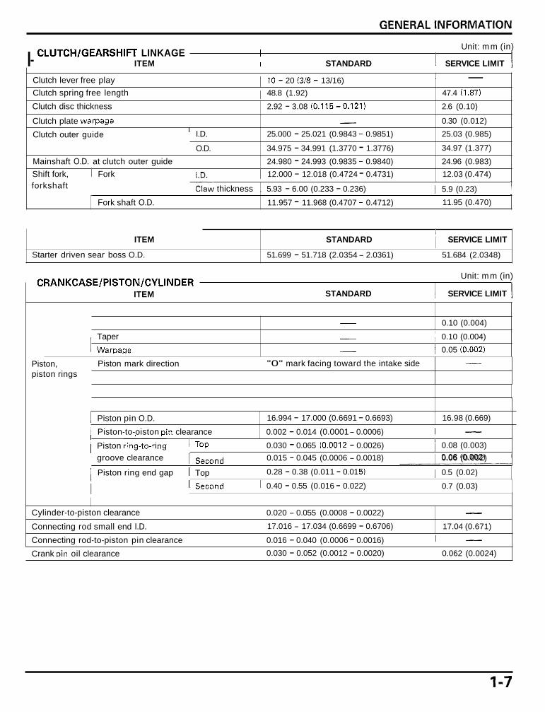
Unit: mm (in)
I- ITEM I STANDARD 1 SERVICE LIMIT I CLUTCH/GEARSHIFT LINKAGE 1
- 1 Clutch lever free play 1 I0 - 20 (3/8 - 13/16) Clutch spring free length 1 48.8 (1.92) 47.4 (1.87)
Clutch disc thickness 2.92 - 3.08 (0.115-0.121) 2.6 (0.10)
Clutch plate warpage
Clutch outer guide
- 0.30 (0.012)
' I.D. 25.000 - 25.021 (0.9843 - 0.9851) 25.03 (0.985)
34.97 (1.377)
24.96 (0.983) Mainshaft O.D. at clutch outer guide Shift fork, I Fork 1 12.000 - 12.018 (0.4724 - 0.4731) 12.03 (0.474)
~ E w thickness , 5.93 - 6.00 (0.233 - 0.236) 1 5.9 (0.23) 1 forkshaft ~
1 11.95 (0.470)
~ O.D. 1 34.975 - 34.991 (1.3770 - 1.3776)
24.980 - 24.993 (0.9835 - 0.9840)
Fork shaft O.D. 11.957 - 11.968 (0.4707 - 0.4712)
ITEM STANDARD i SERVICE LIMIT
Starter driven sear boss O.D. 51.699 - 51.718 (2.0354 - 2.0361) i 51.684 (2.0348)
Unit: mm (in)
STANDARD I SERVICE LIMIT I CRANKCASE/PISTON/CYLINDER I ITEM
- 0.10 (0.004) ,
Piston, piston rings
I Taper
1 WarDase
- , 0.10 (0.004)
- ~ 0.05 (0.002)
1 "0" mark facing toward the intake side Piston mark direction -
1 Piston pin O.D. 16.994 - 17.000 (0.6691 - 0.6693)
i Piston ring end gap 1 Top 1 0.28 - 0.38 (0.01 1 - 0.01 5) 1 0.5 (0.02)
16.98 (0.669)
I 0.40 - 0.55 (0.016 - 0.022) 1 0.7 (0.03) 1 Second i I
i Piston-to-oiston Din clearance - 0.002 - 0.014 (0.0001 - 0.0006) I
- Connecting rod-to-piston pin clearance 1 0.016 - 0.040 (0.0006 - 0.0016) I ' 0.062 (0.0024) 1 0.030 - 0.052 (0.0012 - 0.0020) Crank Din oil clearance
I j Piston rin$-to-rin'g I TOP i 0.030 - 0.065 (0.001 2 - 0.0026) i 0.08 (0.003) groove clearance I Second I 0.015 - 0.045 (0.0006 - 0.0018) I 0.06 (0.002)
Cylinder-to-piston clearance
Connecting rod small end I.D.
1 0.020 - 0.055 (0.0008 - 0.0022)
I 17.016 - 17.034 (0.6699 - 0.6706)
- 17.04 (0.671)

GENERAL INFORMATION
CRANKSHAFT/TRANSMISSlON r ITEM STANDARD
Side clearance
Runout -
Main journal oil clearance Gear I.D. M5, M6 31.000 - 31.025 (1.2205 - 1.2215)
26.000 - 26.021 (1.0236 - 1.0244)
33.000 - 33.025 (1.2992 - 1.3002)
Bushing O.D. M5, M6 30.950 - 30.975 (1.2185 - 1.2195)
32.950 - 32.975 (1.2972 - 1.2982) Bushing I.D. M5 27.985 - 28.006 (1.1018 - 1.1026)
29.985 - 30.006 (1.1805- 1.1813)
0.025 - 0.075 (0.0010 - 0.0030) Gea r-to- bus h i ng clearance c3, c 4 0.025 - 0.075 (0.0010 - 0.0030)
0.05 - 0.20 (0.002 - 0.008)
0.017 - 0.035 (0.0007 - 0.0014)
c 1
c2, c3, c 4
c3, c 4
c 2
M5, M6
SERVICE LIMIT
0.30 (0.012)
0.03 (0.001)
0.045 (0.0018)
31.04 (1.222)
26.04 (1.025)
33.04 (1.301 )
30.93 (1.218)
32.93 (1.296)
28.02 (1.103)
30.02 (1.182)
0.11 (0.004)
0.11 (0.004)
Mainshaft0.D. 1 M5 I 27.967 - 27.980 (1.1011 - 1.1016) 1 27.957 (1.1007)
Countershaft O.D.
Bushing -to-s haft clearance
1 Clutch outer guide I 24.980 - 24.993 (0.9835 - 0.9840) 1 24.96 (0.983) I C2 29.967 - 29.980 (1.1798 - 1.1803) 29.96 (1.180)
M5 0.005 - 0.039 (0.0002 - 0.0015) 0.08 (0.003)
c 2 0.005 - 0.039 (0.0002 - 0.0015) 0.08 (0.003)
1-8

Minimum tire tread depth - 1.5 (0.06) _____
Wheel balance weigh
Fork
Up to 90 kg (200 Ib) load 250 kPa (2.50 kgf/cm2, 36 psi) Cold tire pressure
Up to maximum weight capacity 250 kPa (2.50 kgf/cm2, 36 psi)
- -
Axle runout
Wheel r im runout Radial
Axial
- 0.20 (0.008)
- 2.0 (0.08)
- 2.0 (0.08)
Spring free length
Spring direction
Fork pipe runout
Recommended fork oi l
Fluid level
Fluid capacity
Pre-load adjuster initial setting
Rebound adjuster initial setting
Compression adjuster initial setting
1-9
255.8 (10.07) 250.8 (9.87)
With the tapered end facing up
Pro Honda Suspension Fluid SS-8
73 (2.9)
513 k 2.5 cm3 (17.3 * 0.08 US 02,
18.1 2 0.09 Imp 0 2 )
7 turns f rom full soft
2 turns f rom full hard
2 turns f rom full hard
- - 0.20 (0.008)
- - -
- - -
STANDARD ITEM
- SERVICE LIMIT
2.0 (0.08)
Cold tire pressure Up to 90 kg (200 Ib) load 290 kPa (2.90 kgf/cmz, 42 psi) - Up to maximum weight capacity 290 kPa (2.90 kgf/cm2, 42 psi) -
Axle runout
Wheel rim runout Radial
Axial
- 0.20 (0.008) - 2.0 (0.08)
- 2.0 (0.08)
Wheel balance weight
Drive chain Size/l i n k DID
RK Slack
Spring adjuster standard position
Rebound adjuster initial setting
Compression adjuster initial setting
Shock absorber
- 60 g (2.1 0 2 ) max.
DID 50VA8 C1/108 - RK GB50HFOZ5/108 - 40 - 50 (1.6 - 2.0)
4th groove - 2 turns f rom full hard - 2 turns f rom full hard -
50 (2.0)

GENERAL INFORMATION
r ITEM STANDARD SERVICE LIMIT
Front 1 Specified brake fluid 1 Honda DOT 4 Brake Fluid - 1 I
Rear
Brake disc thickness I 4.5 (0.18) 1 3.5 (0.14)
Brake disc runout - ~ 0.30 (0.012) I I
Specified brake fluid 1 Honda DOT 4 Brake Fluid - I
Brake disc thickness i 5.0 (0.20) 4.0 (0.16)
1 Master cylinder I.D. I 17.460 - 17.503 (0.6874 - 0.6891) 1 17.515 (0.6896) 1
- Brake disc runout I Master cylinder I.D. , 15.870 - 15.913 (0.6248 - 0.6265)
I I 1 Master piston O.D. 1 17.321 - 17.367 (0.6819 - 0.6837) I 17.309 (0.6815) 1
0.30 (0.012)
15.925 (0.6270)
1 32.025 - 32.035 (1.2608 - 1.2612) , 32.05 (1.262)
Lower 30.250 - 30.280 (1.1909 - 1.1921) 1 30.29 (1.193)
Caliper cylinder I.D. ~ Upper
Caliper cylinder I.D.
Caliper cylinder O.D.
Caliper piston O.D. Upper ~ 31,965 - 31.998 (1.2585 - 1.2598) I 31.953 (1.2580) I
I Lower j 30.082 - 30.115 (1.1843 - 1.1856) i 30.074 (1.1840)
38.180 - 38.230 (1.5031 - 1.5051)
38.098 - 38.148 (1.4999 - 1.5019)
38.24 (1.506)
38.090 (1.4996)
Battery Capacity 12V - 8.6 Ah
Current leakage 0.2 m A max.
1 Master t7iston O.D. 1 15.827 - 15.854 (0.6231 - 0.6242) 1 15.815 (0.6226) I
Voltage (2O"C/68'F) Fully charged 13.0 - 13.2 V
Needs charging Below 12.3 V
Charging current Normal 1 Quick
0.9 A/5 - 10 h
4.0 A10.5 h
Alternator Capacity 0.421 kW/5,000 rpm
Charging coil resistance (2O"C/68"F) 0.1 - 1.0 R
- IGNITION SYSTEM ITEM S PECl Fl CAT1 ONS
Spark plug Standard IMR9C-9H (NGK), VUH27D (DENSO)
~ Optional IMR8C-9H (NGK), VUH24D (DENSO)
0.80 - 0.90 m m (0.031 - 0.035 in)
100 V minimum
0.7 V minimum
13" BTDC at idle
I Spark plug gap
Ignition coil peak voltage
Ignition pulse generator peak voltage
Ignition t iming ("F" mark) 1
7-70

GENERAL INFORMATION
SPECIFICATIONS
12v - 5 5 w x 2
12V - 55W
ITEM
Hi
! Lo LED
1 Bulbs
1 Brakehail light
Front turn signal light
Rear turn signal light i License light
Instrument light
Turn signal indicator
High beam indicator
Neutral indicator
Oil pressure indicator
PGM-FI warning indicator
Fuel reserve indicator
Fuse Main fuse
PGM-FI fuse
Sub fuse
Tachometer peak voltage
Thermo sensor resistance 80 "C (176°F) 1 120 'C (248°F)
Starter motor brush length 1 10.0 - 10.5 (0.39 - 0.41) 3.5 (0.14)
12V - 32 /3~p (23/8W) X 2
12V - 32cp (23W) X 2
12V - 5W
LED LED X 2
LED LED LED LED LED 30 A
20 A
20A X 2, 10A X 3
10.5V minimum
2.1 - 2.6 kQ
0.65 - 0.73 kQ
1-11

GENERAL INFORMATION
5 m m hex bolt and nut 5 (0.5, 3.6)
TORQUE VALUES
5 mm screw 4 (0.4, 2.9)
FASTENER TYPE
10 m m hex bolt and nut 12 m m hex bolt and nut
34 (3.5, 25) 54 (5.5, 40)
I TORQUE N-m (kgf-m, Ibf-ft) I
small flange) 6 mm flange bolt (8 m m head, large flange)
I 12 (1.2, 9)
FASTENER TYPE TORQUE
~ N-m (kgf-m, Ibfbft)
- Torque specifications listed below are for important fasteners. Others should be tightened to standard torque values listed above.
NOTES: 1. Apply sealant to the threads. 2. Apply a locking agent to the threads. 3. Apply grease to the threads. 4. Stake. 5. Apply oil to the threads and flange surface. 6. Apply clean engine oil to the O-ring. 7. U-nut 8. ALOC bolt: replace with a new one. 9. CT bolt
10. Apply molybdenum disulfide oil to the threads and seating surface (after removing anti-rust oil additive). 11. One-way bolt
r ENGINE , 1 I I I
ITEM
MAINTENANCE: Spark plug Timing hole cap Oil drain bolt Oil filter cartridge
Oil cooler mounting bolt Oil pump assembly flange bolt Oil pump driven sprocket bolt Oil pressure switch Oil pressure switch wire terminal screw Lower crankcase 20 rnm sealing bolt
ECT (Engine Coolant Temperature)/thermo sensor Throttle body insulator band screw Throttle cable bracket mounting bolt Fuel pipe mounting bolt Pressure regulator mounting bolt Starter valve synchronization plate screw Fast idle wax unit link plate screw Fast idle wax unit mounting screw Starter valve lock nut
Water pump cover flange bolt Thermostat cover flange bolt
Drive sprocket special bolt
LUBRICATION SYSTEM:
FUEL SYSTEM (Programmed Fuel Injection):
COOLING SYSTEM:
ENGINE MOUNTING:
O'TY
2 2
1
TORQUE 1 REMARKS ;;RE:) ~ N-m (kgf-m, I b f W
10 45 12 20
20 6 6
PT 118 4
20
12 5 5 6 6 3 3 6 10
6 6
10
12 (1.2, 9) 18 (1.8, 13) 29 (3.0, 22) 26 (2.7, 20)
74 (7.5, 54) 8 (0.8, 5.8) 15 (1.5, 11) 12 (1.2, 9) 2 (0.2, 1.4) 29 (3.0, 22)
23 (2.3, 17) See page 1-14 3 (0.35, 2.5) 10 (1.0, 7) 10 (1.0, 7)
1 (0.09, 0.7) 1 (0.09, 0.7) 5 (0.5, 3.6)
2 (0.18, 1.3)
12 (1.2, 9) 12 (1.2, 9)
54 (5.5, 40)
NOTE 3
NOTE 6
NOTE 9 NOTE 2 NOTE 1
NOTE 2
NOTE 9 NOTE 9
1-12

GENERAL INFORMATION
r ENGINE (Cont’d) I I 1
ITEM
CYLINDER HEADNALVES: Cylinder head cover bolt PAIR reed valve cover flange bolt Breather plate flange bolt Camshaft holder flange bolt Cylinder head sealing bolt Cylinder head mounting bolt Cylinder head mounting bolt/washer Cam sprocket bolt Cam pulse generator rotor bolt Cam chain tensioner pivot socket bolt Cam chain guide mounting socket bolt Cylinder head stud bolt (exhaust pipe stud bolt)
Clutch center lock nut Clutch spring boltiwasher Shift drum center socket bolt Shift drum stopper arm pivot bolt Gearshift return spring pin S h ift d ru m bea ri n g/s h ift fork retaining bolt/was h er
Alternator wire clamp bolt Flywheel flange bolt Stator mounting socket bolt Starter one-way clutch torx bolt
CRANKCASE/PISTON/CY LINDER: Mainshaft bearing set plate bolt Crankcase bolt, 10 m m
CLUTCH/GEARSHIFT LINKAGE:
ALTERNATORETARTER CLUTCH:
9 mm (main journal bolt)
4 4 3
20 1 2 10 4 2 1 1 8
3 1
10
6 6 6 6 18 8 9 7 6 6 6 8
22 6 8 6 8 6
6 10 6 6
6 10 9
8 mm ‘ 12 Connecting rod nut Upper crankcase skaling bolt Lower crankcase 20 m m sealing bolt Lower crankcase 10 m m socket bolt 10
I
I REMARKS 1 TORQUE N.m (kgf-m, IbfW
10 (1.0,7) 12 (1.2, 9) 12 (1.2, 9) 12 (1.2, 9)
27 (2.8, 20) 25 (2.5, 18) 51 (5.2, 38) 20 (2.0, 14) 12 (1.2,9) 10 (1.0, 7) 12 (1.2! 9)
See page 1-14
127 (1 3.0, 94) 12 (1.2, 9)
23 (2.3, 17) 12 (1.2,9)
23 (2.3, 17) 12 (1.2, 9)
14 (1.4, 10) 103 (10.5, 76)
12 (1.2, 9) 16 (1.6, 12)
12 (1.2, 9) 39 (4.0, 29)
20 (2.0, 14) + 150”
25 (2.5, 18) 35 (3.6, 26) 22 (2.2, 16) 29 (3.0, 22) 12 (1.2, 6.5)
NOTE 2 NOTE 2 NOTE 5 NOTE 2 NOTE 5 NOTE 10 NOTE 2 NOTE 2 NOTE 2 NOTE 2
NOTE 4,5
NOTE 2
NOTE 2
NOTE 9 NOTE 5
NOTE 2
NOTE 2
See page 11-12 NOTE 5
NOTE 5 NOTE 2 NOTE 2 NOTE 2
1-13

GENERAL INFORMATION
DIA. (rnrn)
r ENGINE (Cont'd) I I
N m (kgfm, IbfW ITEM
IG N IT10 N SYSTEM : Ignition pulse generator rotor mounting bolt
ELECTRIC STARTER: Starter motor terminal nut
LIGHTS/METERS/SWITCHES: Neutral switch
Q'TY 4
REMARKS
NOTE 5
Insulator clamp (Throttle body side):
7 1 mm (0.3 i 0.04 in) -4 't
Exhaust
insulator clamp (Cylinder head side):
12 2 1 mm (0.5 i: 0.04 in) -4 it
1-14

GENERAL INFORMATION
- FRAME
ITEM ~
FRAME BODY PANELWEXHAUST SYSTEM: Upper cowl stay mounting bolt Upper cowl stay mounting SH bolt Upper cowl pan screw Lower cowl pan screw Rear cowl truss screw Pillion seat mounting nut Pillion seat hinge special screw Duct cover pan screw Windscreen mounting screw Seat rail mounting bolt, 8 mm Seat rail mounting nut, 10 mm Pillion step mounting socket bolt Exhaust pipe joint nut
Fuel filler cap bolt Fuel hose banjo bolt (fuel tank side) Fuel hose sealing nut (throttle body side) Fuel pump mounting nut
FUEL SYSTEM (Programmed Fuel Injection):
(see tightening sequence below)
FRONT f
Bank angle sensor mounting screw Exhaust valve mounting bolt (front)
(rear) Exhaust valve cover mounting bolt Exhaust valve pulley nut Exhaust valve pulley cover mounting bolt 02 sensor (California type only)
COOLING SYSTEM: Cooling fan nut Fan motor nut Fan motor shroud mounting bolt
Main footpeg bracket mounting socket bolt Main footpeg mounting bolt Lower bracket mounting nut
ENGINE MOUNTING:
Lower bracket mounting pinch bolt Engine hanger bolt (front) Engine hanger bolt (middle) Engine hanger nut (rear) Rear engine hanger pinch bolt Side stand bracket bolt Side stand pivot bolt Side stand pivot lock nut
I 1 REMARKS TORQUE I N-m (kgf-m, Ibf-ft)
8
4
2
2
7 5 8
8 7
5
4 1
4 1 2 1 10
8 '
7 ' 4 12
1 12 6 i 6
6 6
2 1 4 ' 3 4~ 6
1 1 6
1 i 12
5
3 1 6 3 I / 5
8
2
1
2
1 10
- 26 (2.7, 20) 7 (0.7, 5.1) 1.5 (0.15, 1.1) 1.5 (0.15, 1.1) 1 1.5 (0.15, 1.1) ' 11 (1.1, 8) 1 NOTE7 12 (1,2,9)
0.3 (0.03, 0.22) 1.5 (0.15, 1.1)
39 (4.0, 29) 39 (4.0, 29) 39 (4.0, 29)
See page 2-8
12 (1.2, 9) I
2 (0.2, 1.4) 22 (2.2, 16) 22 (2.2, 16) 12 (1.2, 9)
1 1 (1.1, 8) 14 (1.4, 10) 14 (1.4, 10) 12 (1.2, 9) 12 (1.2, 9) 12 (1.2, 9) 25 (2.6, 19)
3 (0.3, 2.2) 5 (0.5, 3.6) 8 (0.8, 5.8)
39 (4.0, 29)
42 (4.3, 31)
26 (2.7, 20) 39 (4.0, 29)
54 (5.5, 40) 26 (2.7, 20) 44 (4.5, 33) 10 (1.0, 7) 29 (3.0, 22) i NOTE 7
44 (4.5, 33) 4 NOTE 8 See page 7-12 NOTE 7
1-15

GENERAL INFORMATION
FRAME (Cont'd)
ITEM
CLUTCH/GEARSHIFT LINKAGE: Gearshift pedal link pinch bolt
FRONT WHEEL/SUSPENSION/STEERING: Handlebar pinch bolt Handlebar weight mountign screw Steering stem nut Steering stem adjusting nut Steering stem lock nut Fork top bridge pinch bolt Fork bottom bridge pinch bolt Front axle bolt Front axle holder pinch bolt Front brake disc mounting bolt Fork bolt Fork center bolt
Rear axle nut Rear brake disc mounting bolt Driven sprocket nut Rear shock absorber upper mounting nut Rear shock absorber upper bracket mounting nut Shock arm plate nut Shock link nut (frame side) Swingarm pivot nut Swingarm pivot pinch bolt Drive chain slider bolt
Front brake master cylinder cup mounting nut Brake lever pivot bolt Brake lever pivot nut Front brake light switch screw Front brake caliper mounting bolt Caliper body assembly torx bolt Front caliper pad pin Rear caliper pad pin Rear caliper pad pin plug Brake caliper bleeder Rear brake hose clamp screw Brake pedal joint nut Rear master cylinder push rod lock nut Rear master cylinder hose joint screw Rear brake caliper pin bolt Rear brake caliper bolt Brake hose oil bolt LIGHTS/METERS/SWITCHES: Ignition switch mounting one-way bolt Side stand switch mountinq bolt
REAR WHEEL/SUSPENSION:
HYDRAULIC BRAKE:
Q'TY
1
2 2 1 1 1 2 4 1 4 12 2 2
1 4 6 1 1 3 1 1 2 3
1 1 1 1 4 8 4 1 1 3 1 1 1 1 1 1 5
2 1
THREAD DIA. (mm)
6
8 6
24 26 26 8 8 18 8 6 42 10
22 8 10 10 16 10 10 24 8 6
6 6 6 4 8 8 10 10 10 8 5 8 8 4 12 8 10
8 6
TORQUE N-m (kgf-m, Ibf*ft)
10 (1.0, 7 )
26 (2.7, 20) 10 (1.0, 7)
I;: ;;005\;q -
23 (2.3, 17) 26 (2.7, 20) 78 (8.0, 58) 22 (2.2, 16) 20 (2.0, 14) 23 (2.3, 17) 34 (3.5, 25)
113 (11.5, 83) 42 (4.3, 31) 64 (6.5, 47) 44 (4.5, 33) 93 (9.5, 69) 44 (4.5, 33) 44 (4.5, 33)
118 (12.0, 87) 26 (2.7, 20) 9 (0.9, 6.5)
6 (0.6, 4.3) 1 (0.1, 0.7) 6 (0.6, 4.3) 1 (0.1, 0.7) 30 (3.1, 22) 23 (2.3, 17) 18 (1.8, 13) 18 (1.8, 13) 3 (0.3, 2.2) 6 (0.6, 4.3) 4 (0.4, 2.9) 18 (1.8, 13) 18 (1.8, 13) 1 (0.15, 1.1) 27 (2.8, 20) 23 (2.3, 17) 34 (3.5, 25)
26 (2.7, 20) 10 (1.0, 7 )
REMARKS
NOTE 8
NOTE 8 See page 13-30
NOTE 8
NOTE 7 NOTE 8 NOTE 7 NOTE 7 NOTE 7 NOTE 7 NOTE 7 NOTE 7
NOTE 8
NOTE 7
NOTE 8 NOTE 2
NOTE 8
NOTE 2 NOTE 2 NOTE 2
NOTE 11
1-16
GENERAL INFORMATION
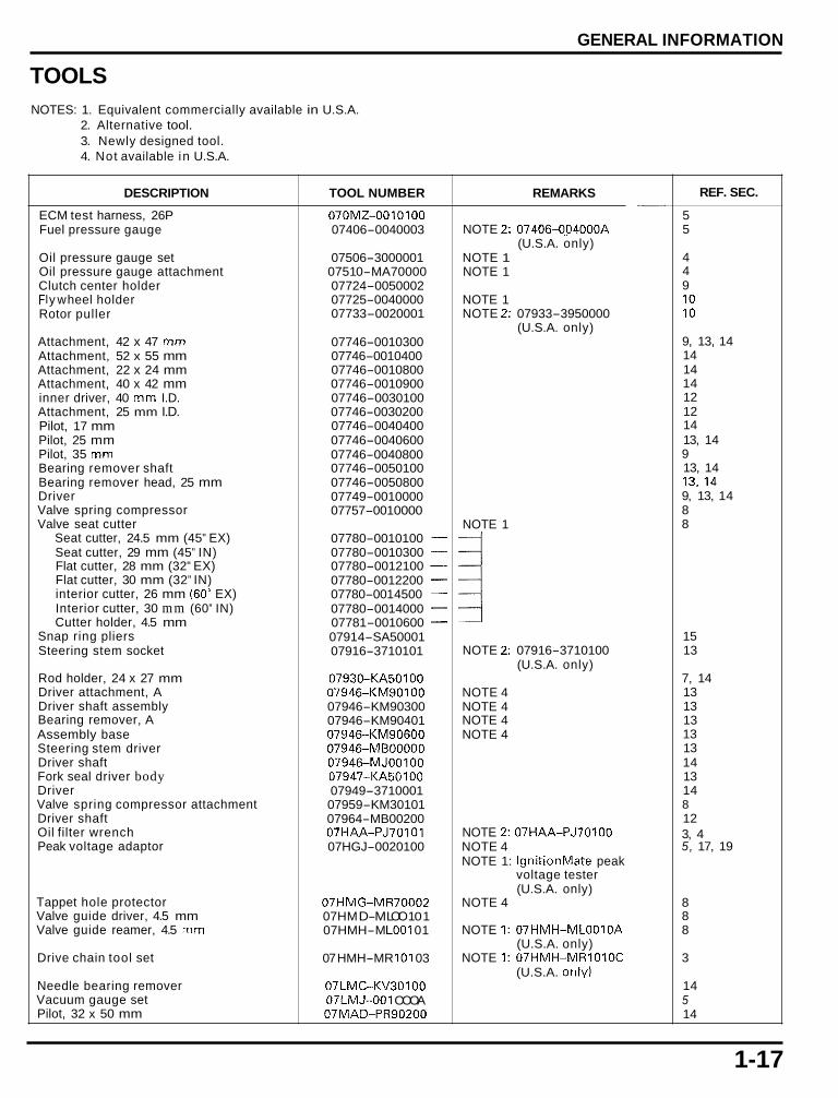
TOOLS NOTES: 1. Equivalent commercially available in U.S.A.
2. Alternative tool. 3. Newly designed tool. 4. Not available in U.S.A.
DESCRIPTION
ECM test harness, 26P Fuel pressure gauge
Oil pressure gauge set Oil pressure gauge attachment Clutch center holder FI y w heel holder Rotor puller
Attachment, 42 x 47 mm Attachment, 52 x 55 mm Attachment, 22 x 24 mm Attachment, 40 x 42 mm inner driver, 40 mm I.D. Attachment, 25 mm I.D. Pilot, 17 mm Pilot, 25 mm Pilot, 35 mm Bearing remover shaft Bearing remover head, 25 mm Driver Valve spring compressor Valve seat cutter
Seat cutter, 24.5 mm (45" EX) Seat cutter, 29 mm (45" IN) Flat cutter, 28 mm (32" EX) Flat cutter, 30 mm (32" IN) interior cutter, 26 mm (60" EX) Interior cutter, 30 mm (60" IN) Cutter holder, 4.5 mm
Snap ring pliers Steering stem socket
Rod holder, 24 x 27 mm Driver attachment, A Driver shaft assembly Bearing remover, A Assembly base Steering stem driver Driver shaft Fork seal driver body Driver Valve spring compressor attachment Driver shaft Oil filter wrench Peak voltage adaptor
Tappet hole protector Valve guide driver, 4.5 mm Valve guide reamer, 4.5 mm
Drive chain tool set
Needle bearing remover Vacuum gauge set Pilot, 32 x 50 mm
TOOL NUMBER
070MZ-0010100 07406-0040003
07506-3000001 0751 0-MA70000 07724-0050002 07725-0040000 07733-0020001
07746-0010300 07746-001 0400 07746-0010800 07746-0010900 07746-0030100 07746-0030200 07746-0040400 07746-0040600 07746-0040800 07746-0050100 07746-0050800 07749-0010000 07757-001 0000
07780-0010100 - 07780-0010300 - 07780-0012100 - 07780-0012200 - 07780-001 4500 - 07780-0014000 - 07781-0010600 - 0791 4-SA50001 07916-3710101
07930-KA50100 07946-KM90 100 07946-KM90300 07946-KM90401 07946-KM90600 07946-MB00000 07946-MJ00100 07947-KA50100 07949-3710001 07959-KM30101 07964-MB00200 07HAA-PJ70101 07HGJ-0020100
07HMG-MR70002 07H M D-M LOO 1 0 1 07HMH-M LOO1 01
07 HMH-MR 101 03
07LMC-KV30100 07iMJ-001 OOOA 07MAD-PR90200
REMARKS
NOTE 2: 07406-OO4000A (U.S.A. only)
NOTE 1 NOTE 1
NOTE 1 NOTE 2: 07933-3950000
(U.S.A. only)
NOTE 1
1 NOTE 2: 07916-3710100
(U.S.A. only)
NOTE 4 NOTE 4 NOTE 4 NOTE 4
NOTE 2: 07HAA-PJ70100 NOTE 4 NOTE 1: IgnitionMate peak
voltage tester (U.S.A. only)
NOTE 4
NOTE 1: 07HMH-MLOOIOA (U.S.A. only)
(U.S.A. only) NOTE 1: 07HMH-MR1010C
REF. SEC.
5 5
4 4 9 10 10
9, 13, 14 14 14 14 12 12 14 13, 14 9 13, 14 13,14 9, 13, 14 8 8
15 13
7, 14 13 13 13 13 13 14 13 14 8 12 3, 4 5, 17, 19
8 8 8
3
14 5 14
1-17

GENERAL INFORMATION
DESCRIPTION
Race remover Driver attachment Compression gauge attachment Fork damper holder handle Installer attachment, A Installer attachment, B Remover attachment, A Remover attachment, B Fork damper holder Oil seal driver
Driver attachment, 25 x 38.5 m m Installer shaft guide
Installer shaft
installer shaft, 14 x 30 m m
Remover, 14 x 16 m m
Cam chain tensioner holder Batterv tester
TOOL NUMBER
07NMF-MT70110 07NMF-MT70120 07RMJ-MY50100 07TMB-00101 OA 07VMF-MAT0100 07VMF-MAT0200 07VMF-MAT0300 07VMF-MAT0400 07YMB-MCF0101 07YMD-MCFOI 00
07Y M D-MCJOI 00 07YMF-MCJOI 00
07YMF-MCJ0200
07Y M F-M CJ 0300
07YMF-MCJ0400
07ZM G-MCAA400 BM-210-AH
REMARKS
NOTE 4 NOTE 4
U.S.A. only U.S.A. only U.S.A. only U.S.A. only
NOTE 1: 07NMD-KZ301OA (U.S.A. only)
NOTE 2: 07YMF-MCJA100
NOTE 2: 07YMF-MCJA200
NOTE 2: 07YMF-MCJA300
NOTE 2: 07YMF-MCJA400
(U.S.A. only)
(U.S.A. only)
(U.S.A. only)
(U.S.A. only) U.S.A. only NOTE 2: BM-210 (U.S.A. only)
REF. SEC.
13 ,I 3 8 13 13 13 13 13 13 13
14 5
5
5
5
3, 8 16
1-18

GENERAL INFORMATION
LUBRICATION & SEAL POINTS
LOCATION REMARKS MATERIAL
~
)iI pan mating surface I I
Liquid sealant Crankcase mating surface 1 (Three Bond 1207B or 1
3ight crankcase cover mating surface I
Oil pressure switch threads
Do not apply sealant to the thread 1 d 3 - 4 mm (0.1 - 0.2 in) I
I
I
1-19

GENERAL INFORMATION
ENGINE (Cont'd) LOCATION
Cylinder head semi-circular cut-out
Main journal bearing surface Piston pin sliding surface Connecting rod bearing surface Connecting rod small end inner surface Crankshaft thrust surface Camshaft lobes/journals and thrust surface Valve stem (valve guide sliding surface) Valve lifter outer sliding surface Clutch outeriprimary driven gear sliding surface Clutch outer guide sliding surface M314, C5, C6 shifter gear (shift fork grooves) Starter reduction gear shaft outer surface Cylinder head special bolt (after removing anti-rust oil additive) Primary sub-gear friction spring sliding surface
/c7f-===$ I APPLICATION AREA
Piston ring sliding area Oil strainer packing Clutch disc surface Starter one-way clutch sliding surface Connecting rod nut threads Flywheel bolt threads and seating surface Main journal 9 m m bolt threads and seating surface (after removing anti-rust oil additive) Clutch center lock nut threads Oil filter cartridge threads and O-ring Camshaft holder bolt threads and seating surface Oil cooler center bolt threads Each gear teeth and rotating surface Each bearing rotating area Each O-ring Other rotating area and sliding surface
MATERIAL
Sealant
Molybdenum disulfide oil (a mixture of 1/2 engine oil and 1/2 m o I ybdenum d isulfide grease
Engine oil
REMARKS
1-20

GENERAL INFORMATION
MATERIAL
1 Multi-purpose grease j LOCATION
Timing hole cap threads Each oil seal lip
Upper crankcase sealing bolt threads I ~ Locking agent
Lower crankcase sealing bolt threads Cam chain guide A mounting bolt threads Cam pulse generator rotor bolt threads Cylinder head sealing bolt threads Cylinder head cover breather joint threads Starter one-way clutch outer bolt threads Oil pump driven sprocket bolt threads Shift drum bearing set plate bolt threads Mainshaft bearing set plate bolt threads Cam sprocket bolt threads Cylinder head cover breather plate bolt threads Shift drum center bolt threads Cam chain tensioner pivot bolt threads Cam chain guide pivot bolt threads Gearshift return spring pin
REMARKS
Coating width: 6.5 2 1 m m
4 -21
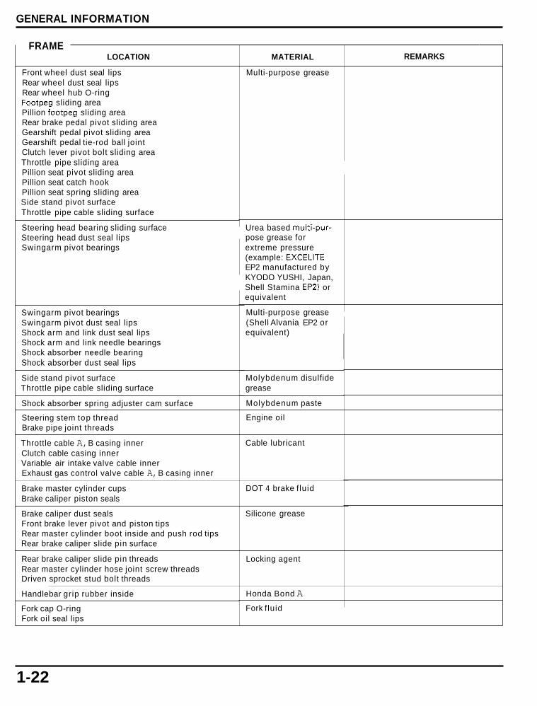
GENERAL INFORMATION
FRAME LOCATION
Front wheel dust seal lips Rear wheel dust seal lips Rear wheel hub O-ring Footpeg sliding area Pillion footpeg sliding area Rear brake pedal pivot sliding area Gearshift pedal pivot sliding area Gearshift pedal tie-rod ball joint Clutch lever pivot bolt sliding area Throttle pipe sliding area Pillion seat pivot sliding area Pillion seat catch hook Pillion seat spring sliding area Side stand pivot surface Throttle pipe cable sliding surface
Steering head bearing sliding surface Steering head dust seal lips Swingarm pivot bearings
Swingarm pivot bearings Swingarm pivot dust seal lips Shock arm and link dust seal lips Shock arm and link needle bearings Shock absorber needle bearing Shock absorber dust seal lips
Side stand pivot surface Throttle pipe cable sliding surface
Shock absorber spring adjuster cam surface
Steering stem top thread Brake pipe joint threads
Throttle cable A, B casing inner Clutch cable casing inner Variable air intake valve cable inner Exhaust gas control valve cable A, B casing inner
Brake master cylinder cups Brake caliper piston seals
Brake caliper dust seals Front brake lever pivot and piston tips Rear master cylinder boot inside and push rod tips Rear brake caliper slide pin surface
Rear brake caliper slide pin threads Rear master cylinder hose joint screw threads Driven sprocket stud bolt threads ____ ~~~
Handlebar grip rubber inside
Fork cap O-ring Fork oil seal lips
MATERIAL
Multi-purpose grease
Urea based multi-pur- pose grease for extreme pressure (example: EXCELITE EP2 manufactured by KYODO YUSHI, Japan, Shell Stamina EP2) or equivalent
Multi-purpose grease (Shell Alvania EP2 or equivalent)
Molybdenum disulfide grease
Molybdenum paste
Engine oil
Cable lubricant
DOT 4 brake f luid
Silicone grease
Locking agent
Honda Bond A Fork f luid
REMARKS
1-22

GENERAL INFORMATION
CABLE & HARNESS ROUTING
BANK ANGLE SENSOR
/
\ HEAD LIGHT CONNECTOR (Hi)
RIGHT TURN ~ I G N A L CON N ECTORS
HEAD LIGHT CONNECTOR (H i )
1-23

GENERAL INFORMATION
CLUTCH CABLE
I
MAIN
\ HORN WIRE
1-24

GENERAL INFORMATION
FRONT BdAKE HOSE
1-25

GENERAL INFORMATION
'I -26

GENERAL INFORMATION
EXCEPT CALIFORNIA TYPE:
STARTER MOTOR'GROUND CABLE
1-27

GENERAL INFORMATION ~~
CALIFORNIA TYPE:
PAIR CONTROL SOLENOID VALVE 2P (NATURAL) CONNECTOR
GROUND
1-28
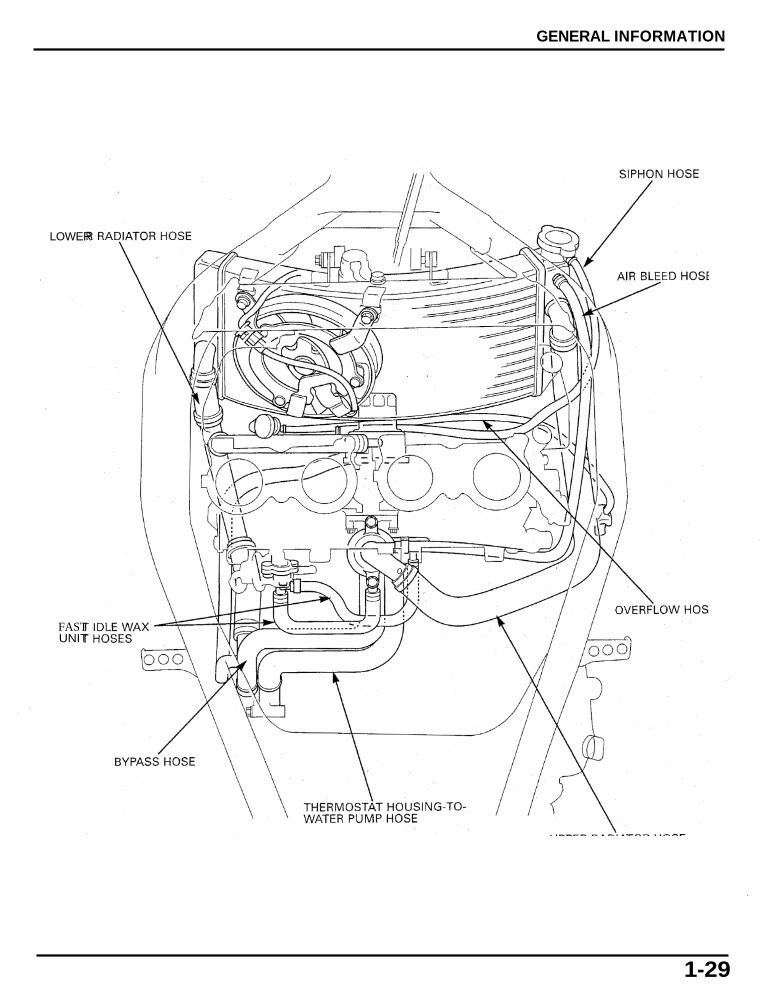
GENERAL INFORMATION
LOWER
FAST UNIT
1-29

GENERAL INFORMATION
THROTTLE STOP CONTROL CABLE
FUEL TANK AIR VENT HOSE V
EGCV C O N T ~ O L CABLES
1-30

GENERAL INFORMATION
PAIR SUCTION HOSE
SIPHON HOSE FUEL TANK AIR VENT HOSE
FUEL TANK OVERFLOW
\
.EED
IGNITION PULSE \ GENERATOR WIRE
\ RESERVOIR TANK OVERFLOW HOSE
1-31
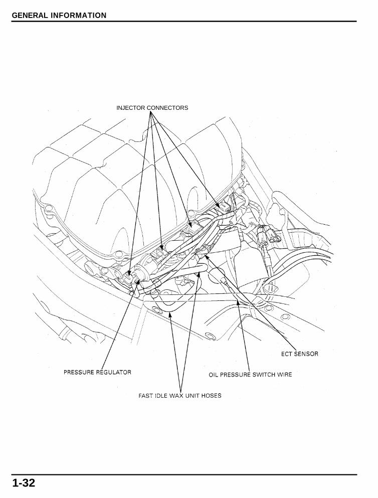
GENERAL INFORMATION
INJECTOR CONNECTORS
1-32

GENERAL INFORMATION
IAT SENSOR
H CONNECTOR
KE VALVE SERVO MOTOR CONNECTOR MAP SENSOR - SPEED SENSOR VACUUM HOSE CONNECTOR
FUEL HOSE \
1-33

GENERAL INFORMATION
REAR BRAKE LIGHT SWITCH CON N ECTOR
I BATTERY NEGATIVE (-1 CABLE \
\ ECM 26P (LIGHT GRAY) CONNECTOR I FUSE BOX
/
ECM 26P (BLACK) CON N ECTOR I
ALTERNATOR 3P (WHITE) CONNECTOR
1-34

GENERAL INFORMATION
HEADLIGHT RELAY
/ CONNECTOR BOOT:
REAR TURN SIGNAL LIGHT CONNECTOR LICENSE LIGHT CONNECTOR BRAKEFAIL LIGHT CONNECTOR
/ /
0 2 SENSOR WIRE (California type only)
REAR BRAKE LIGHT SWITCH WlRE \
REAR BRAKE LIGHT SWITCH
1-35

GENERAL INFORMATION
REAR BRAKE HOSE
\ \
RESERVOIR HOSE
/
REAR BRAKE LIGHT SWITCH
1-36

GENERAL INFORMATION
EMISSION CONTROL SYSTEMS The U.S. Environmental Protection Agency, California Air Resources Board (CARB) and Transport Canada require manufac- turers to certify that their motorcycles comply with applicable exhaust emissions standards during their useful life, when oper- ated and maintained according to the instructions provided, and that motorcycles built after January 1, 1983 comply with applicable noise emission standards for one year or 6,000 km (3,730 miles) after the t ime of sale t o the ultimate purchaser, when operated and maintained according to the instructions provided. Compliance with the terms of the Distributor's Limited Warranty for Honda Motorcycle Emission Control Systems is necessary in order t o keep the emissions system warranty in effect.
SOURCE OF EMISSIONS
The combustion process produces carbon monoxide and hydrocarbons. Control of hydrocarbons is very important because, under certain conditions, they react t o form photochemical smog when subjected to sunlight. Carbon monoxide does not react in the same way, but it is toxic. Honda Motor Co., Ltd. utilizes lean injection settings as wel l as other systems, t o reduce carbon monoxide and hydrocarbons.
CRANKCASE EMISSION CONTROL SYSTEM
The engine is equipped with a closed crankcase system t o prevent discharging crankcase emissions into the atmosphere. Blow-by gas is returned to the combustion chamber through the air cleaner and throttle body.
AIR CLEANER HOUSING
/
FRESH AIR
BLOW-BY GAS

GENERAL INFORMATION
EXHAUST EMISSION CONTROL SYSTEM (SECONDARY AIR SUPPLY SYSTEM)
The exhaust emission control system is composed of a lean fuel injection setting, and no adjustments should be made except idle speed adjustment with the throttle stop screw. The exhaust emission control system is separate from the crankcase emis- sion control system.
The exhaust emission control system also includes a secondary air supply system which introduces filtered air into the exhaust gases in the exhaust port. Fresh air is drawn into the exhaust port by the function of the PAIR (Pulse Secondary Air Injection) control valve. This charge of fresh air promotes burning of the unburned exhaust gases and changes a considerable amount of hydrocar- bons and carbon monoxide into relatively harmless carbon dioxide and water vapor.
The reed valve prevents reverse air flow through the system. The PAIR control valve is operated by the solenoid valve. The solenoid valve is controlled by the PGM-FI unit, and the fresh air passage is opened/closed according the running condition ( E CT/I AT/TP/M A P sensor a n d en g i n e rev0 I u t i o n ) .
No adjustments to the secondary air supply system should be made, although periodic inspection of the components is recommended.
AIR CLEANER HOUSING
California type: The California type is equipped with two three-way warm-up catalytic converters, a three-way catalytic converter, and a heated oxygen sensor. The three-way catalytic converters are in the exhaust system. Through chemical reactions, they convert HC, CO, and NOx in the engine’s exhaust to carbon dioxide (COZ), dinitrogen (Nz), and water vapor. No adjustment to these systems should be made although periodic inspection of the components is recommended.
1-38

GENERAL INFORMATION
EVAPORATIVE EMISSION CONTROL SYSTEM (CALIFORNIA TYPE ONLY)
This model complies wi th CARB evaporative emission requirements. Fuel vapor f rom the fuel tank is routed into the evaporative emission (EVAP) canister where it is absorbed and stored while the engine is stopped. When the engine is running and the evaporative emission (EVAP) purge control solenoid valve is open, fuel vapor in the EVAP canister is drawn into the engine through the throttle body.
FUEL TANK
THROTTLE BODY EVAP PURGE CONTROL SOLENOID VALVE
a FRESH AIR
FUELVAPOR
NOISE EMISSION CONTROL SYSTEM
TAMPERING WITH THE NOISE CONTROL SYSTEM IS PROHIBITED: U S . Federal law prohibits, or Canadian provincial law pro- hibits the following acts or the causing there of: (1) The removal o r rending inoperative by any person, other than for the pur- poses of maintenance, repair or replacement, of any device or element of design incorporated into any vehicle for the purpose of noise control prior t o its sale or delivery t o the ultimate customer or while it is in use; or 12) the use of any vehicle after such device or element of design has been removed or rendered inoperative by any person.
AMONG THOSE ACTS PRESUMED TO CONSTITUTE TAMPERING ARE THE ACTS LISTED BELOW: 1. Removal of, or puncturing of the muffler, baffles, header pipes or any other component which conducts exhaust gases. 2. Removal of, or puncturing of any part of the intake system. 3. Lack of proper maintenance. 4. Replacing any moving parts of the vehicle, or parts of the exhaust or intake system, wi th parts other then those specified
by the manufacturer.
1-39
GENERAL INFORMATION
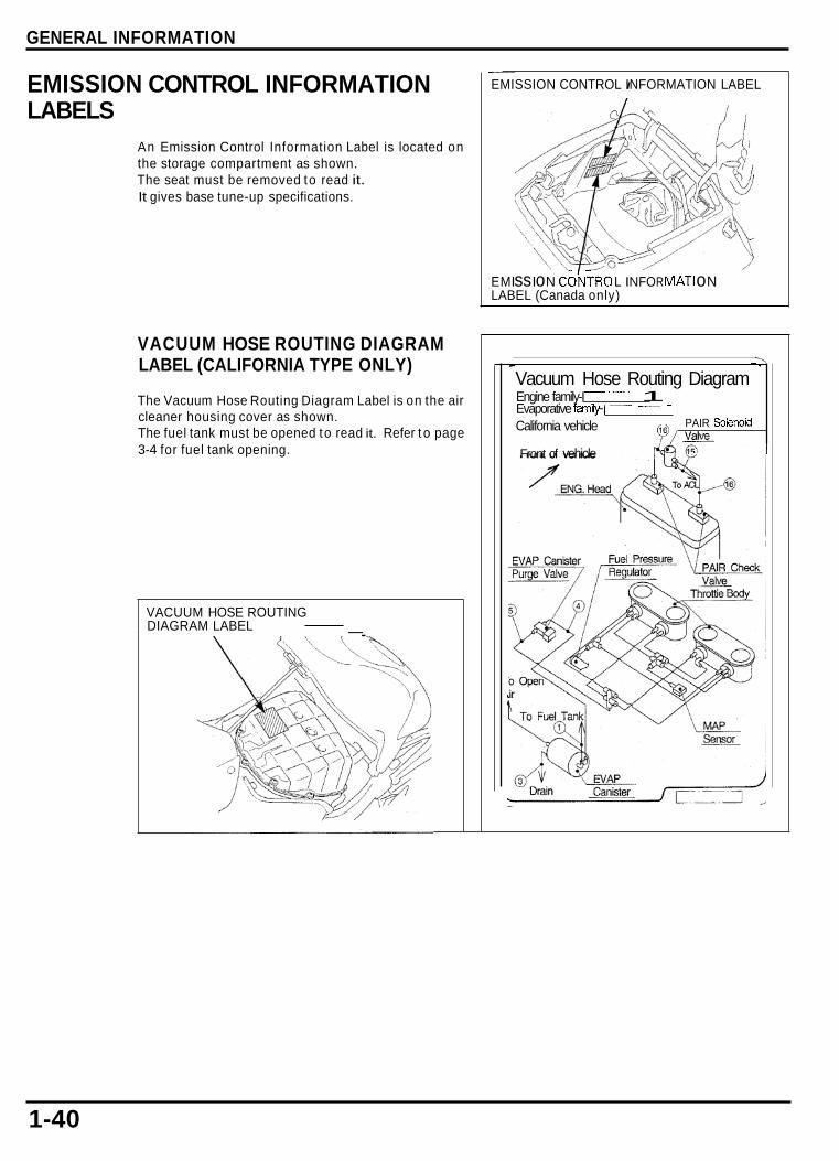
EMISSION CONTROL INFORMATION LABELS
An Emission Control Information Label is located on the storage compartment as shown. The seat must be removed to read it. It gives base tune-up specifications.
VACUUM HOSE ROUTING DIAGRAM LABEL (CALIFORNIA TYPE ONLY)
The Vacuum Hose Routing Diagram Label is on the air cleaner housing cover as shown. The fuel tank must be opened to read it. Refer t o page 3-4 for fuel tank opening.
VACUUM HOSE ROUTING DIAGRAM LABEL -.
~~
EMISSION CONTROL INFORMATION I LABEL
EM I ss I o N C O ~ T R O L I N FO R MATI o N LABEL (Canada only)
\ - 7
Vacuum Hose Routing Diagram - _.__ Engine family-I 1 Evaporative family-\ ~ - ~ - 1 California vehicle PAIR Solenoid F/ valve Front of vehicle
-
1-40