general information chapter 1 · (6) parts requiring angle tightening • when tightening the...
TRANSCRIPT
GENERAL INFORMATIONCHAPTER 1
CONTENTSHOW TO USE THIS MANUAL ............................... 1-2
Description ........................................................ 1-2Definition of Terms ............................................ 1-2Definition of Units .............................................. 1-2Description ........................................................ 1-2
PRECAUTIONS FOR SAFETY AND QUALITY .... 1-3Safe Operation .................................................. 1-3Correct Operation .............................................. 1-4Precautions for Radio Equipment Installation ... 1-4
PRECAUTIONS ..................................................... 1-5Precautions in Draining Engine Coolant ............ 1-5Precautions for Disconnecting Fuel Piping ........ 1-5Precautions for Removing and Disassembling .. 1-5Precautions for Inspection, Correction, and Replacement ..................................................... 1-5
Precautions for Assembly and Installation ........ 1-5Parts Requiring Angle Tightening ...................... 1-6Caution for Use of Power Tools ........................ 1-6Precautions for Liquid Gasket Application ......... 1-6
TIGHTENING TORQUE ......................................... 1-7Standard Bolt Tightening Torque ...................... 1-7Engine Part Tightening Torque ......................... 1-8
SPECIAL SERVICE TOOLS ................................ 1-10ENGINE OUTSIDE DRAWING ............................ 1-11MAIN SPECIFICATIONS ..................................... 1-12STANDARD AND REPAIR LIMIT ....................... 1-15STAMPED LOCATION OF ENGINE NO. ............ 1-18TROUBLE SHOOTING ........................................ 1-19
Engine Adjustment .......................................... 1-20Engine LPG Fuel System ................................ 1-25
DO NOT DISASSEMBLE ENGINE OR ENGINE COMPONENTS DURING THEWARRANTY PERIOD. DISASSEMBLY OF ENGINE OR COMPONENTS MAY
VOID THE WARRANTY. SEE YOUR WARRANTY CERTIFICATE FOR DETAILS.
PLEASE CONTACT YOUR KOMATSU SERVICE REPRESENTATIVE FOR AUTHORIZATION AND/OR GUIDANCE FOR ANY WORK INVOLVING DISASSEMBLY DURING THE WARRANTY PERIOD.
1-2
HOW TO USE THIS MANUAL
HOW TO USE THIS MANUAL (1) DescriptionThis manual explains how to use "removal, installation, disassembly,assembly, inspection and adjustment" and "troubleshooting".
(2) Definition of TermsWARNING: Instructions and precautions that may lead to fatal
hazards and/or serious injuries if not observed properly.CAUTION: Instructions and precautions that require special
attention and may lead to problems and/or accidents aswell as damages to the vehicle and/or components.
NOTE: Provides additional information that facilitatesoperation.
Standard: Indicates tolerances for inspection and adjustment.Repair limit: Indicates maximum or minimum values allowed for
inspection and adjustment.
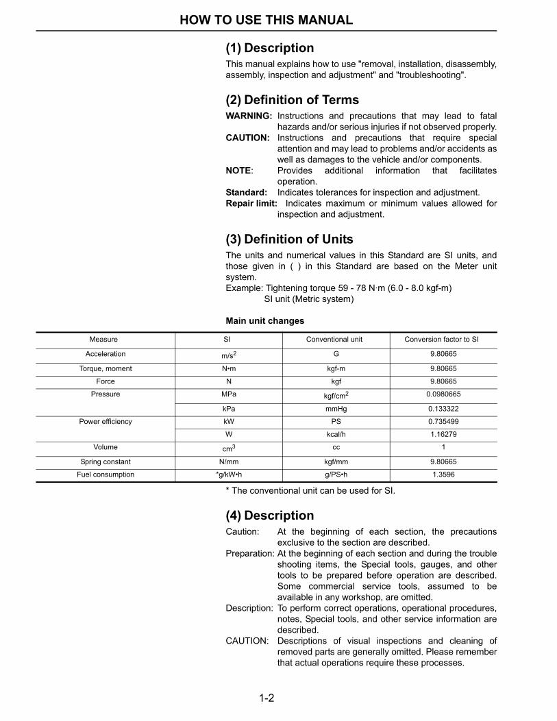
(3) Definition of UnitsThe units and numerical values in this Standard are SI units, andthose given in ( ) in this Standard are based on the Meter unitsystem.Example: Tightening torque 59 - 78 N·m (6.0 - 8.0 kgf-m)
SI unit (Metric system)
Main unit changes
* The conventional unit can be used for SI.
(4) DescriptionCaution: At the beginning of each section, the precautions
exclusive to the section are described.Preparation: At the beginning of each section and during the trouble
shooting items, the Special tools, gauges, and othertools to be prepared before operation are described.Some commercial service tools, assumed to beavailable in any workshop, are omitted.
Description: To perform correct operations, operational procedures,notes, Special tools, and other service information aredescribed.
CAUTION: Descriptions of visual inspections and cleaning ofremoved parts are generally omitted. Please rememberthat actual operations require these processes.
Measure SI Conventional unit Conversion factor to SI
Acceleration m/s2 G 9.80665
Torque, moment N•m kgf-m 9.80665
Force N kgf 9.80665
Pressure MPa kgf/cm2 0.0980665
kPa mmHg 0.133322
Power efficiency kW PS 0.735499
W kcal/h 1.16279
Volume cm3 cc 1
Spring constant N/mm kgf/mm 9.80665
Fuel consumption *g/kW•h g/PS•h 1.3596
1-3
PRECAUTIONS FOR SAFETY AND QUALITY
PRECAUTIONS FOR SAFETY AND QUALITY • The following precautions must be carefully observed for safeand appropriate service work.
• Only the qualified and designated personnel must performinspections, repairs and adjustments.
• Always keep the workplace clean, and store the tools neatly inthe specified places.
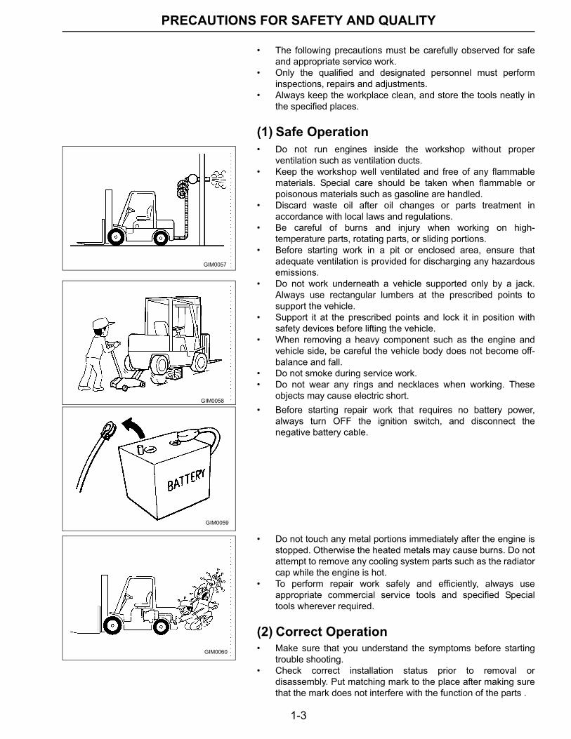
(1) Safe Operation• Do not run engines inside the workshop without proper
ventilation such as ventilation ducts.• Keep the workshop well ventilated and free of any flammable
materials. Special care should be taken when flammable orpoisonous materials such as gasoline are handled.
• Discard waste oil after oil changes or parts treatment inaccordance with local laws and regulations.
• Be careful of burns and injury when working on high-temperature parts, rotating parts, or sliding portions.
• Before starting work in a pit or enclosed area, ensure thatadequate ventilation is provided for discharging any hazardousemissions.
• Do not work underneath a vehicle supported only by a jack.Always use rectangular lumbers at the prescribed points tosupport the vehicle.
• Support it at the prescribed points and lock it in position withsafety devices before lifting the vehicle.
• When removing a heavy component such as the engine andvehicle side, be careful the vehicle body does not become off-balance and fall.
• Do not smoke during service work.• Do not wear any rings and necklaces when working. These
objects may cause electric short.• Before starting repair work that requires no battery power,
always turn OFF the ignition switch, and disconnect thenegative battery cable.
• Do not touch any metal portions immediately after the engine isstopped. Otherwise the heated metals may cause burns. Do notattempt to remove any cooling system parts such as the radiatorcap while the engine is hot.
• To perform repair work safely and efficiently, always useappropriate commercial service tools and specified Specialtools wherever required.
(2) Correct Operation• Make sure that you understand the symptoms before starting
trouble shooting.• Check correct installation status prior to removal or
disassembly. Put matching mark to the place after making surethat the mark does not interfere with the function of the parts .
GIM0057
GIM0058
GIM0059
GIM0060
1-4
PRECAUTIONS FOR SAFETY AND QUALITY
• Once they are removed, always replace parts indicated as "donot reuse" with new ones. This includes: oil seals, gaskets,packings, O-rings, lock washers, cotter pins, and self-lockingnuts.
• Replace inner and outer races of tapered or needle rollerbearings as a set.
• Arrange disassembled parts in order and prevent them frombeing mixed-up.
• Clean or flush disassembled parts prior to inspection orassembly.
• Use Genuine parts for replacement.• Use authorized grease and sealer.• Release the pressure before disconnecting pressurized piping
or hoses.• Be sure to check for leakage after repairing fuel, oil, coolant,
exhaust, or vacuum systems.
(3) Precautions for Radio Equipment Installation
Check the following when installing a commercial/ham radio ormobile phone. If mounting position is not chosen carefully, the unitmay interfere with the electronic control system.• Separate the antenna as far from the Engine Control System as
possible.• Route an antenna feeder line at least 20 cm apart from the
control unit harness.• Adjust antenna and feeder line to eliminate radio wave
interference.
1-5
PRECAUTIONS
PRECAUTIONS (1) Precautions in Draining Engine Coolant• Drain coolant only after the engine has cooled down.
(2) Precautions for Disconnecting Fuel Piping
• Operation should be done in a place free from fire.• Release fuel pressure before operation. (Electronic controlled
specifications): Refer to "Release of Fuel Pressure" in ECsection.
• After disconnecting, plug the pipe to prevent fuel from draining.
(3) Precautions for Removing and Disassembling
• Use correct special tools in the specified position. Always payattention to safety.
• Be careful not to lose surface accuracy of mating or slidingsurfaces.
• To prevent foreign material from entering the engine, closeopenings with appropriate tape as necessary.
• Arrange disassembled parts in their normal positions in order tosimplify locating the cause of damage or excessive wear and toensure correct reassembly.
• As a rule, nuts and bolts must be tightened in a diagonalmanner starting from an outer one. If a particular tighteningsequence is provided separately, follow the sequence.
(4) Precautions for Inspection, Correction, and Replacement
• Following the inspection procedure, inspect the partsadequately and repair or replace as necessary. Perform thesame inspections even for new parts and replace them ifnecessary.
(5) Precautions for Assembly and Installation• Always use a torque wrench when tightening bolts and nuts.• Unless otherwise specified, tighten nuts and bolts from inside to
outside in a crisscross pattern. Tighten them gradually andevenly in 2 to 3 steps.
• Always replace gasket, packing, oil seals, and O-rings with newones.
• For each part, perform adequate cleaning/washing and dryingwith a dryer. In particular, ensure that the oil and coolantpassages are free from plugging and clogging.
• Remove any dirt and lint on sliding and mating surfaces. Beforeassembly, apply ample amount of engine oil to sliding surfaces.
• If coolant was drained, bleed air from the system.• After assembly, start engine and increase the engine speed,
then check coolant, fuel, oil, grease, and exhaust gas forleakage.
1-6
PRECAUTIONS
(6) Parts Requiring Angle Tightening• When tightening the following parts, use an angle wrench
(Special tool).• Cylinder head bolt
Before assembly, verify that no grease/oil and dust are present on the cylinder head, cylinder block mounting face, and head gasket. Then apply antirust oil or engine oil to the threads and head bottoms of the head bolts.
(7) Caution for Use of Power Tools• The use of power tools such as an air runner is only allowed for
disassembly. Do not use them for assembly.
(8) Precautions for Liquid Gasket Application
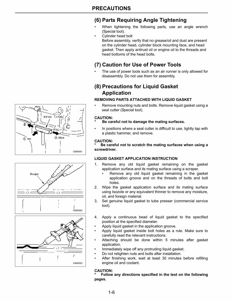
REMOVING PARTS ATTACHED WITH LIQUID GASKET• Remove mounting nuts and bolts. Remove liquid gasket using a
seal cutter (Special tool).
CAUTION:* Be careful not to damage the mating surfaces.
• In positions where a seal cutter is difficult to use, lightly tap witha plastic hammer, and remove.
CAUTION:* Be careful not to scratch the mating surfaces when using ascrewdriver.
LIQUID GASKET APPLICATION INSTRUCTION1. Remove any old liquid gasket remaining on the gasket
application surface and its mating surface using a scraper.• Remove any old liquid gasket remaining in the gasket
application groove and on the threads of bolts and boltholes.
2. Wipe the gasket application surface and its mating surfaceusing Isozole or any equivalent thinner to remove any moisture,oil, and foreign material.
3. Set genuine liquid gasket to tube presser (commercial servicetool).
4. Apply a continuous bead of liquid gasket to the specifiedposition at the specified diameter.
• Apply liquid gasket in the application groove.• Apply liquid gasket inside bolt holes as a rule. Make sure to
carefully read the relevant instructions.• Attaching should be done within 5 minutes after gasket
application.• Immediately wipe off any protruding liquid gasket.• Do not retighten nuts and bolts after installation.• After finishing work, wait at least 30 minutes before refilling
engine oil and coolant.
CAUTION:* Follow any directions specified in the text on the followingpages.
GIM0061
GIM0062
GIM0063
1-7
TIGHTENING TORQUE
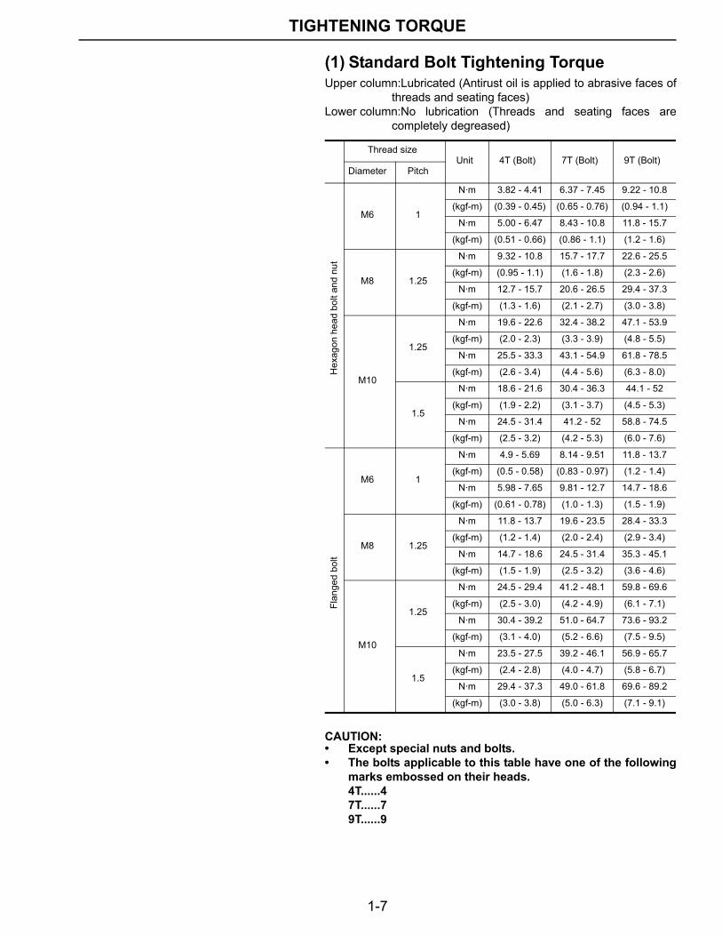
TIGHTENING TORQUE (1) Standard Bolt Tightening TorqueUpper column:Lubricated (Antirust oil is applied to abrasive faces of
threads and seating faces)Lower column:No lubrication (Threads and seating faces are
completely degreased)
CAUTION:• Except special nuts and bolts.• The bolts applicable to this table have one of the following
marks embossed on their heads.4T......47T......79T......9
Thread sizeUnit 4T (Bolt) 7T (Bolt) 9T (Bolt)
Diameter Pitch
Hex
agon
hea
d bo
lt an
d nu
t
M6 1
N·m 3.82 - 4.41 6.37 - 7.45 9.22 - 10.8
(kgf-m) (0.39 - 0.45) (0.65 - 0.76) (0.94 - 1.1)
N·m 5.00 - 6.47 8.43 - 10.8 11.8 - 15.7
(kgf-m) (0.51 - 0.66) (0.86 - 1.1) (1.2 - 1.6)
M8 1.25
N·m 9.32 - 10.8 15.7 - 17.7 22.6 - 25.5
(kgf-m) (0.95 - 1.1) (1.6 - 1.8) (2.3 - 2.6)
N·m 12.7 - 15.7 20.6 - 26.5 29.4 - 37.3
(kgf-m) (1.3 - 1.6) (2.1 - 2.7) (3.0 - 3.8)
M10
1.25
N·m 19.6 - 22.6 32.4 - 38.2 47.1 - 53.9
(kgf-m) (2.0 - 2.3) (3.3 - 3.9) (4.8 - 5.5)
N·m 25.5 - 33.3 43.1 - 54.9 61.8 - 78.5
(kgf-m) (2.6 - 3.4) (4.4 - 5.6) (6.3 - 8.0)
1.5
N·m 18.6 - 21.6 30.4 - 36.3 44.1 - 52
(kgf-m) (1.9 - 2.2) (3.1 - 3.7) (4.5 - 5.3)
N·m 24.5 - 31.4 41.2 - 52 58.8 - 74.5
(kgf-m) (2.5 - 3.2) (4.2 - 5.3) (6.0 - 7.6)
Flan
ged
bolt
M6 1
N·m 4.9 - 5.69 8.14 - 9.51 11.8 - 13.7
(kgf-m) (0.5 - 0.58) (0.83 - 0.97) (1.2 - 1.4)
N·m 5.98 - 7.65 9.81 - 12.7 14.7 - 18.6
(kgf-m) (0.61 - 0.78) (1.0 - 1.3) (1.5 - 1.9)
M8 1.25
N·m 11.8 - 13.7 19.6 - 23.5 28.4 - 33.3
(kgf-m) (1.2 - 1.4) (2.0 - 2.4) (2.9 - 3.4)
N·m 14.7 - 18.6 24.5 - 31.4 35.3 - 45.1
(kgf-m) (1.5 - 1.9) (2.5 - 3.2) (3.6 - 4.6)
M10
1.25
N·m 24.5 - 29.4 41.2 - 48.1 59.8 - 69.6
(kgf-m) (2.5 - 3.0) (4.2 - 4.9) (6.1 - 7.1)
N·m 30.4 - 39.2 51.0 - 64.7 73.6 - 93.2
(kgf-m) (3.1 - 4.0) (5.2 - 6.6) (7.5 - 9.5)
1.5
N·m 23.5 - 27.5 39.2 - 46.1 56.9 - 65.7
(kgf-m) (2.4 - 2.8) (4.0 - 4.7) (5.8 - 6.7)
N·m 29.4 - 37.3 49.0 - 61.8 69.6 - 89.2
(kgf-m) (3.0 - 3.8) (5.0 - 6.3) (7.1 - 9.1)
1-8
TIGHTENING TORQUE
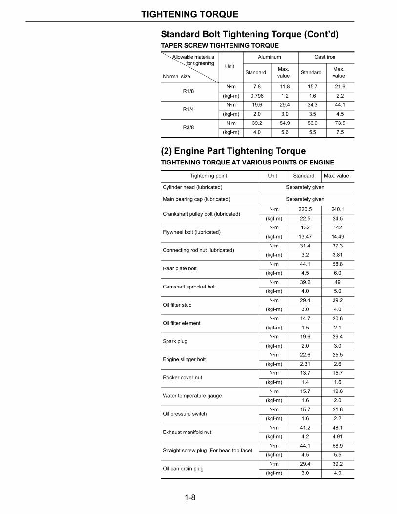
Standard Bolt Tightening Torque (Cont’d)TAPER SCREW TIGHTENING TORQUE
(2) Engine Part Tightening TorqueTIGHTENING TORQUE AT VARIOUS POINTS OF ENGINE
Allowable materialsfor tightening
Normal size
Unit
Aluminum Cast iron
Standard Max. value Standard Max.
value
R1/8N·m 7.8 11.8 15.7 21.6
(kgf-m) 0.796 1.2 1.6 2.2
R1/4N·m 19.6 29.4 34.3 44.1
(kgf-m) 2.0 3.0 3.5 4.5
R3/8N·m 39.2 54.9 53.9 73.5
(kgf-m) 4.0 5.6 5.5 7.5
Tightening point Unit Standard Max. value
Cylinder head (lubricated) Separately given
Main bearing cap (lubricated) Separately given
Crankshaft pulley bolt (lubricated)N·m 220.5 240.1
(kgf-m) 22.5 24.5
Flywheel bolt (lubricated)N·m 132 142
(kgf-m) 13.47 14.49
Connecting rod nut (lubricated)N·m 31.4 37.3
(kgf-m) 3.2 3.81
Rear plate boltN·m 44.1 58.8
(kgf-m) 4.5 6.0
Camshaft sprocket boltN·m 39.2 49
(kgf-m) 4.0 5.0
Oil filter studN·m 29.4 39.2
(kgf-m) 3.0 4.0
Oil filter elementN·m 14.7 20.6
(kgf-m) 1.5 2.1
Spark plugN·m 19.6 29.4
(kgf-m) 2.0 3.0
Engine slinger boltN·m 22.6 25.5
(kgf-m) 2.31 2.6
Rocker cover nutN·m 13.7 15.7
(kgf-m) 1.4 1.6
Water temperature gaugeN·m 15.7 19.6
(kgf-m) 1.6 2.0
Oil pressure switchN·m 15.7 21.6
(kgf-m) 1.6 2.2
Exhaust manifold nutN·m 41.2 48.1
(kgf-m) 4.2 4.91
Straight screw plug (For head top face)N·m 44.1 58.9
(kgf-m) 4.5 5.5
Oil pan drain plugN·m 29.4 39.2
(kgf-m) 3.0 4.0
1-9
TIGHTENING TORQUE
Engine Part Tightening Torque (Cont’d)
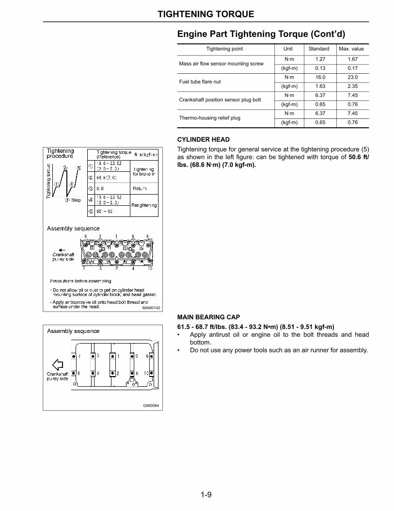
CYLINDER HEADTightening torque for general service at the tightening procedure (5)as shown in the left figure: can be tightened with torque of 50.6 ft/lbs. (68.6 N·m) (7.0 kgf-m).
MAIN BEARING CAP61.5 - 68.7 ft/lbs. (83.4 - 93.2 N•m) (8.51 - 9.51 kgf-m)• Apply antirust oil or engine oil to the bolt threads and head
bottom.• Do not use any power tools such as an air runner for assembly.
Tightening point Unit Standard Max. value
Mass air flow sensor mounting screwN·m 1.27 1.67
(kgf-m) 0.13 0.17
Fuel tube flare nutN·m 16.0 23.0
(kgf-m) 1.63 2.35
Crankshaft position sensor plug boltN·m 6.37 7.45
(kgf-m) 0.65 0.76
Thermo-housing relief plugN·m 6.37 7.45
(kgf-m) 0.65 0.76
MAM0142
GIM0064
1-10
SPECIAL SERVICE TOOLS
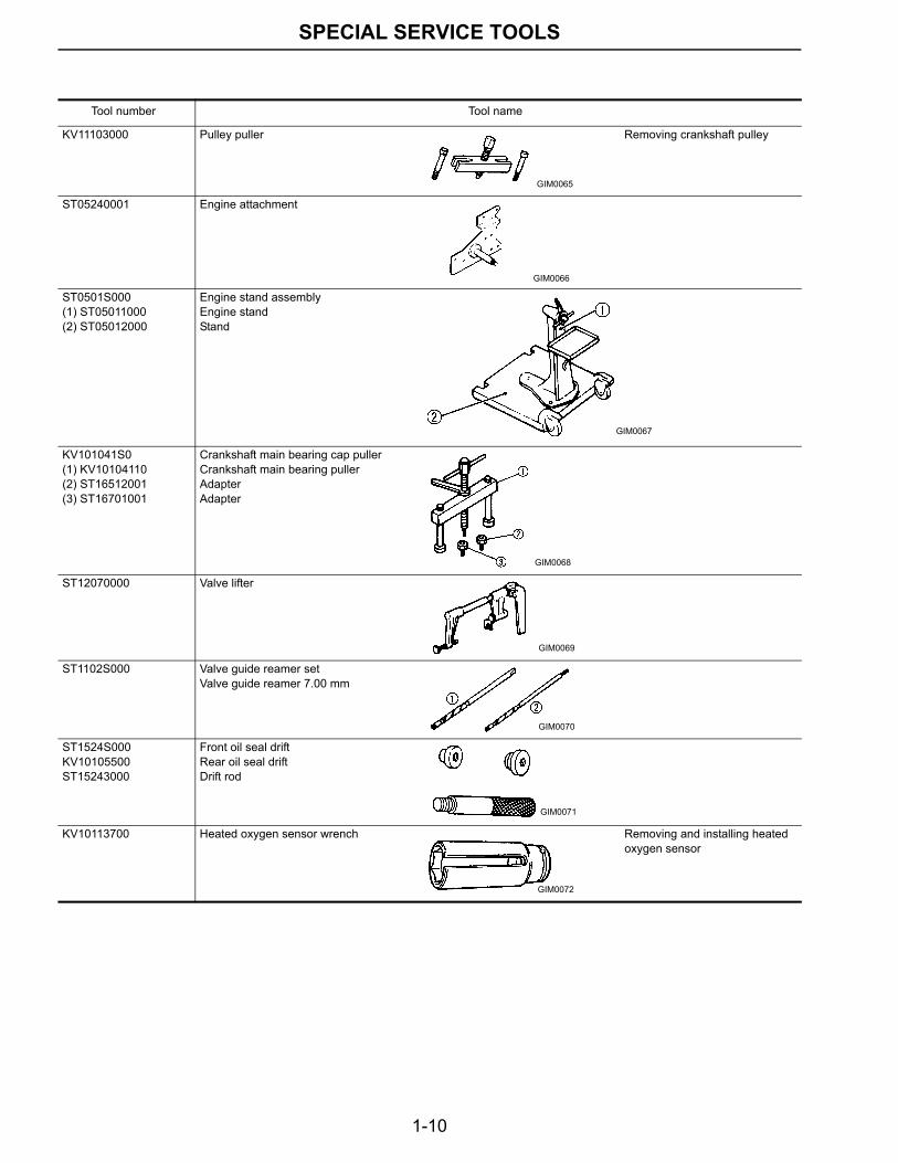
SPECIAL SERVICE TOOLSTool number Tool name
KV11103000 Pulley puller Removing crankshaft pulley
ST05240001 Engine attachment
ST0501S000(1) ST05011000(2) ST05012000
Engine stand assemblyEngine standStand
KV101041S0(1) KV10104110(2) ST16512001(3) ST16701001
Crankshaft main bearing cap pullerCrankshaft main bearing pullerAdapterAdapter
ST12070000 Valve lifter
ST1102S000 Valve guide reamer setValve guide reamer 7.00 mm
ST1524S000KV10105500ST15243000
Front oil seal driftRear oil seal driftDrift rod
KV10113700 Heated oxygen sensor wrench Removing and installing heated oxygen sensor
GIM0065
GIM0066
GIM0067
GIM0068
GIM0069
GIM0070
GIM0071
GIM0072
1-11
ENGINE OUTSIDE DRAWINGS
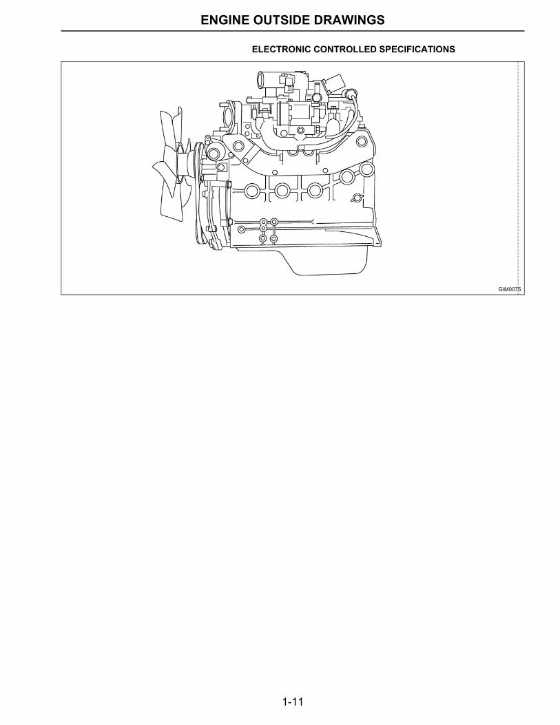
ENGINE OUTSIDE DRAWINGS ELECTRONIC CONTROLLED SPECIFICATIONS
GIM0075
1-12
ENGINE OUTSIDE DRAWINGS
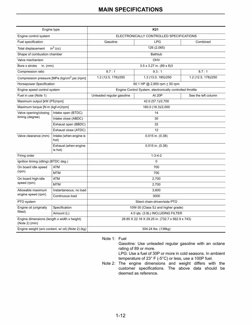
Note 1: FuelGasoline: Use unleaded regular gasoline with an octanerating of 89 or more.LPG: Use a fuel of 30P or more in cold seasons. In ambienttemperature of 23° F (-5°C) or less, use a 100P fuel.
Note 2: The engine dimensions and weight differs with thecustomer specifications. The above data should bedeemed as reference.
Engine type K21
Engine control system ELECTRONICALLY CONTROLLED SPECIFICATIONS
Fuel specification Gasoline LPG Combined
Total displacement in3 (cc) 126 (2,065)
Shape of combustion chamber Bathtub
Valve mechanism OHV
Bore x stroke in. (mm) 3.5 x 3.27 in. (89 x 8)3
Compression ratio 8.7 : 1 9.3 : 1 8.7 : 1
Compression pressure [MPa (kg/cm2,psi )/rpm] 1.2 (12.5, 178)/250 1.3 (13.0, 185)/250 1.2 (12.5, 178)/250
Horsepower Specification 60.1 HP @ 2,950 rpm + 50 rpm
Engine speed control system Engine Control System, electronically controlled throttle
Fuel in use (Note 1) Unleaded regular gasoline At 20P See the left column
Maximum output [kW (PS)/rpm] 42.0 (57.1)/2,700
Maximum torque [N·m (kgf-m)/rpm] 160.0 (16.3)/2,000
Valve opening/closing timing (degree)
Intake open (BTDC) 14
Intake close (ABDC) 30
Exhaust open (BBDC) 32
Exhaust close (ATDC) 12
Valve clearance (mm) Intake (when engine is hot)
0.015 in. (0.38)
Exhaust (when engine is hot)
0.015 in. (0.38)
Firing order 1-3-4-2
Ignition timing (idling) (BTDC deg.) 0
On board idle speed (rpm)
ATM 700
MTM 700
On board high-idle speed (rpm)
ATM 2,700
MTM 2,700
Allowable maximum engine speed (rpm)
Instantaneous, no load 3,600
Continuous load 3000
PTO system Silent chain-driven/side PTO
Engine oil (originally fitted)
Specification 10W-30 (Class SJ and higher grade)
Amount (L) 4.0 qts. (3.8L) INCLUDING FILTER
Engine dimensions (length x width x height) (Note 2) (mm)
28.85 X 22.16 X 29.25 in. (732.7 x 562.9 x 743)
Engine weight (w/o coolant, w/ oil) (Note 2) (kg) 304.24 lbs. (138kg)
MAIN SPECIFICATIONS
1-13
ENGINE OUTSIDE DRAWINGS
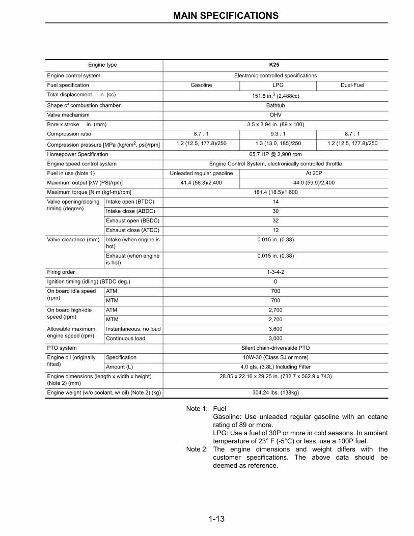
Note 1: FuelGasoline: Use unleaded regular gasoline with an octanerating of 89 or more.LPG: Use a fuel of 30P or more in cold seasons. In ambienttemperature of 23° F (-5°C) or less, use a 100P fuel.
Note 2: The engine dimensions and weight differs with thecustomer specifications. The above data should bedeemed as reference.
Engine type K25
Engine control system Electronic controlled specifications
Fuel specification Gasoline LPG Dual-Fuel
Total displacement in. (cc) 151.8 in.3 (2,488cc)
Shape of combustion chamber Bathtub
Valve mechanism OHV
Bore x stroke in. (mm) 3.5 x 3.94 in. (89 x 100)
Compression ratio 8.7 : 1 9.3 : 1 8.7 : 1
Compression pressure [MPa (kg/cm2, psi)/rpm] 1.2 (12.5, 177.8)/250 1.3 (13.0, 185)/250 1.2 (12.5, 177.8)/250
Horsepower Specification 65.7 HP @ 2,900 rpm
Engine speed control system Engine Control System, electronically controlled throttle
Fuel in use (Note 1) Unleaded regular gasoline At 20P
Maximum output [kW (PS)/rpm] 41.4 (56.3)/2,400 44.0 (59.9)/2,400
Maximum torque [N·m (kgf-m)/rpm] 181.4 (18.5)/1,600
Valve opening/closing timing (degree)
Intake open (BTDC) 14
Intake close (ABDC) 30
Exhaust open (BBDC) 32
Exhaust close (ATDC) 12
Valve clearance (mm) Intake (when engine is hot)
0.015 in. (0.38)
Exhaust (when engine is hot)
0.015 in. (0.38)
Firing order 1-3-4-2
Ignition timing (idling) (BTDC deg.) 0
On board idle speed (rpm)
ATM 700
MTM 700
On board high-idle speed (rpm)
ATM 2,700
MTM 2,700
Allowable maximum engine speed (rpm)
Instantaneous, no load 3,600
Continuous load 3,000
PTO system Silent chain-driven/side PTO
Engine oil (originally fitted)
Specification 10W-30 (Class SJ or more)
Amount (L) 4.0 qts. (3.8L) Including Filter
Engine dimensions (length x width x height) (Note 2) (mm)
28.85 x 22.16 x 29.25 in. (732.7 x 562.9 x 743)
Engine weight (w/o coolant, w/ oil) (Note 2) (kg) 304.24 lbs. (138kg)
MAIN SPECIFICATIONS
1-14
ENGINE OUTSIDE DRAWINGS
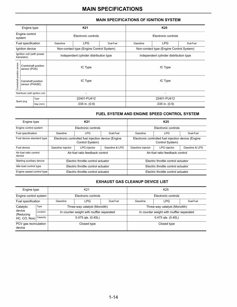
MAIN SPECIFICATIONS OF IGNITION SYSTEM
FUEL SYSTEM AND ENGINE SPEED CONTROL SYSTEM
EXHAUST GAS CLEANUP DEVICE LIST
Engine type K21 K25
Engine control system Electronic controls Electronic controls
Fuel specification Gasoline LPG Dual-Fuel Gasoline LPG Dual-Fuel
Ignition device Non-contact type (Engine Control System) Non-contact type (Engine Control System)Ignition coil (with power transistor) Independent cylinder distribution type Independent cylinder distribution type
Cra
nksh
aft p
ositi
on s
enso
r
Crankshaft position sensor (POS) IC Type IC Type
Camshaft position sensor (PHASE)
IC Type IC Type
Distributor (with ignition coil) - -
Spark plugType 22401-FU412 22401-FU412
Gap (mm) .035 in. (0.9) .035 in. (0.9)
Engine type K21 K25
Engine control system Electronic controls Electronic controlsFuel specification Gasoline LPG Dual-Fuel Gasoline LPG Dual-Fuel
Fuel device standard type Electronic controlled fuel injection device (Engine Control System)
Electronic controlled fuel injection device (Engine Control System)
Fuel device Gasoline injector LPG injector Gasoline & LPG Gasoline injector LPG injector Gasoline & LPG
Air-fuel ratio control device
Air-fuel ratio feedback control Air-fuel ratio feedback control
Starting auxiliary device Electric throttle control actuator Electric throttle control actuatorIdle load control type Electric throttle control actuator Electric throttle control actuatorEngine speed control type Electric throttle control actuator Electric throttle control actuator
Engine type K21 K25
Engine control system Electronic controls Electronic controls
Fuel specification Gasoline LPG Dual-Fuel Gasoline LPG Dual-Fuel
Catalytic device (Reducing HC, CO, Nox)
Type Three-way catalyst (Monolith) Three-way catalyst (Monolith)Location In counter weight with muffler separated In counter weight with muffler separatedCapacity 0.475 qts. (0.45L) 0.475 qts. (0.45L)
PCV gas recirculation device
Closed type Closed type
MAIN SPECIFICATIONS
1-15
STANDARD AND REPAIR LIMIT
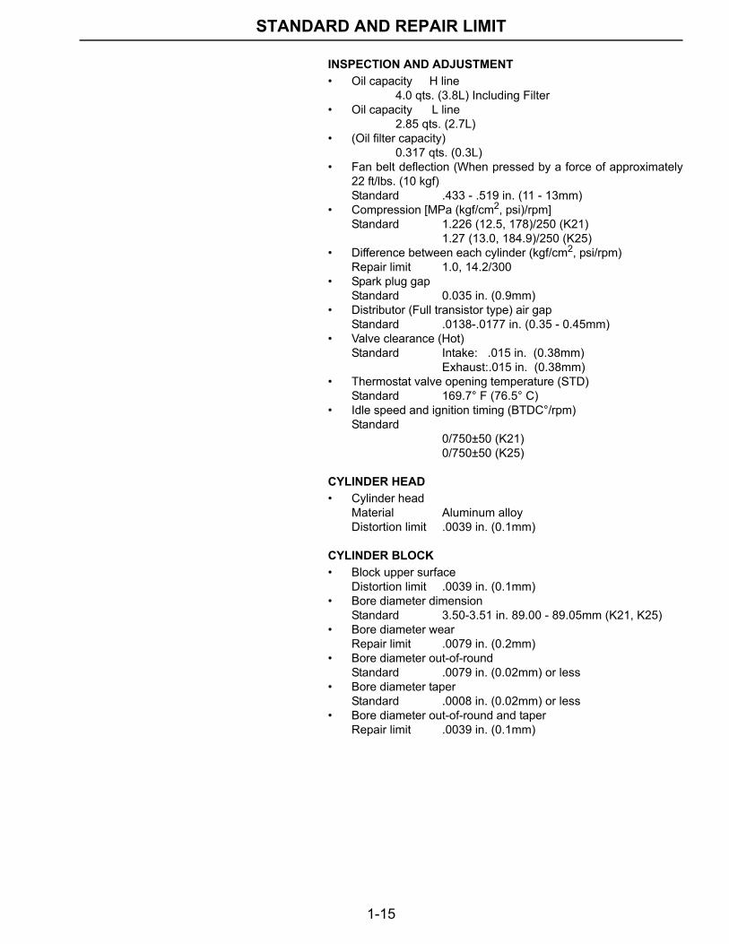
STANDARD AND REPAIR LIMIT INSPECTION AND ADJUSTMENT• Oil capacity H line
4.0 qts. (3.8L) Including Filter• Oil capacity L line
2.85 qts. (2.7L)• (Oil filter capacity)
0.317 qts. (0.3L)• Fan belt deflection (When pressed by a force of approximately
22 ft/lbs. (10 kgf)Standard .433 - .519 in. (11 - 13mm)
• Compression [MPa (kgf/cm2, psi)/rpm]Standard 1.226 (12.5, 178)/250 (K21)
1.27 (13.0, 184.9)/250 (K25)• Difference between each cylinder (kgf/cm2, psi/rpm)
Repair limit 1.0, 14.2/300• Spark plug gap
Standard 0.035 in. (0.9mm)• Distributor (Full transistor type) air gap
Standard .0138-.0177 in. (0.35 - 0.45mm)• Valve clearance (Hot)
Standard Intake: .015 in. (0.38mm)Exhaust:.015 in. (0.38mm)
• Thermostat valve opening temperature (STD)Standard 169.7° F (76.5° C)
• Idle speed and ignition timing (BTDC°/rpm)Standard
0/750±50 (K21)0/750±50 (K25)
CYLINDER HEAD• Cylinder head
Material Aluminum alloyDistortion limit .0039 in. (0.1mm)
CYLINDER BLOCK• Block upper surface
Distortion limit .0039 in. (0.1mm)• Bore diameter dimension
Standard 3.50-3.51 in. 89.00 - 89.05mm (K21, K25)• Bore diameter wear
Repair limit .0079 in. (0.2mm)• Bore diameter out-of-round
Standard .0079 in. (0.02mm) or less• Bore diameter taper
Standard .0008 in. (0.02mm) or less• Bore diameter out-of-round and taper
Repair limit .0039 in. (0.1mm)
1-16
STANDARD AND REPAIR LIMIT
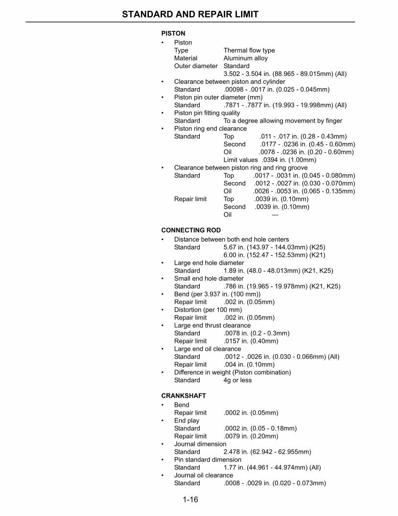
PISTON• Piston
Type Thermal flow typeMaterial Aluminum alloyOuter diameter Standard
3.502 - 3.504 in. (88.965 - 89.015mm) (All)• Clearance between piston and cylinder
Standard .00098 - .0017 in. (0.025 - 0.045mm)• Piston pin outer diameter (mm)
Standard .7871 - .7877 in. (19.993 - 19.998mm) (All)• Piston pin fitting quality
Standard To a degree allowing movement by finger• Piston ring end clearance
Standard Top .011 - .017 in. (0.28 - 0.43mm)Second .0177 - .0236 in. (0.45 - 0.60mm)Oil .0078 - .0236 in. (0.20 - 0.60mm)Limit values .0394 in. (1.00mm)
• Clearance between piston ring and ring grooveStandard Top .0017 - .0031 in. (0.045 - 0.080mm)
Second .0012 - .0027 in. (0.030 - 0.070mm)Oil .0026 - .0053 in. (0.065 - 0.135mm)
Repair limit Top .0039 in. (0.10mm)Second .0039 in. (0.10mm)Oil —
CONNECTING ROD• Distance between both end hole centers
Standard 5.67 in. (143.97 - 144.03mm) (K25)6.00 in. (152.47 - 152.53mm) (K21)
• Large end hole diameterStandard 1.89 in. (48.0 - 48.013mm) (K21, K25)
• Small end hole diameterStandard .786 in. (19.965 - 19.978mm) (K21, K25)
• Bend (per 3.937 in. (100 mm))Repair limit .002 in. (0.05mm)
• Distortion (per 100 mm)Repair limit .002 in. (0.05mm)
• Large end thrust clearanceStandard .0078 in. (0.2 - 0.3mm)Repair limit .0157 in. (0.40mm)
• Large end oil clearanceStandard .0012 - .0026 in. (0.030 - 0.066mm) (All)Repair limit .004 in. (0.10mm)
• Difference in weight (Piston combination)Standard 4g or less
CRANKSHAFT• Bend
Repair limit .0002 in. (0.05mm)• End play
Standard .0002 in. (0.05 - 0.18mm)Repair limit .0079 in. (0.20mm)
• Journal dimensionStandard 2.478 in. (62.942 - 62.955mm)
• Pin standard dimensionStandard 1.77 in. (44.961 - 44.974mm) (All)
• Journal oil clearanceStandard .0008 - .0029 in. (0.020 - 0.073mm)
1-17
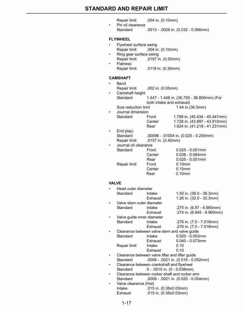
STANDARD AND REPAIR LIMIT
Repair limit .004 in. (0.10mm)• Pin oil clearance
Standard .0013 - .0026 in. (0.032 - 0.066mm)
FLYWHEEL• Flywheel surface swing
Repair limit .004 in. (0.10mm)• Ring gear surface swing
Repair limit .0197 in. (0.50mm)• Flatness
Repair limit .0118 in. (0.30mm)
CAMSHAFT• Bend
Repair limit .002 in. (0.05mm)• Camshaft height
Standard 1.447 - 1.448 in. (36.750 - 36.800mm) (For both intake and exhaust)Size reduction limit 1.44 in.(36.5mm)
• Journal dimensionStandard Front 1.789 in. (45.434 - 45.447mm)
Center 1.728 in. (43.897 - 43.910mm)Rear 1.624 in. (41.218 - 41.231mm)
• End play)Standard .00098 - .01004 in. (0.025 - 0.255mm)Repair limit .0157 in. (0.40mm)
• Journal oil clearanceStandard Front 0.025 - 0.051mm
Center 0.038 - 0.064mmRear 0.025 - 0.051mm
Repair limit Front 0.10mmCenter 0.15mm
Rear 0.10mm
VALVE• Head outer diameter
Standard Intake 1.50 in. (38.0 - 38.3mm)Exhaust 1.26 in. (32.0 - 32.3mm)
• Valve stem outer diameterStandard Intake .275 in. (6.97 - 6.985mm)
Exhaust .274 in. (6.945 - 6.960mm)• Valve guide inner diameter
Standard Intake .276 in. (7.0 - 7.018mm)Exhaust .276 in. (7.0 - 7.018mm)
• Clearance between valve stem and valve guideStandard Intake 0.020 - 0.053mm
Exhaust 0.040 - 0.073mmRepair limit Intake 0.10
Exhaust 0.10• Clearance between valve lifter and lifter guide
Standard .0006 - .0021 in. (0.016 - 0.052mm)• Clearance between crankshaft and flywheel
Standard 0 - .0015 in. (0 - 0.038mm)• Clearance between rocker shaft and rocker arm
Standard .0008 - .0021 in. (0.020 - 0.054mm)• Valve clearance (Hot)
Intake .015 in. (0.38±0.03mm)Exhaust .015 in. (0.38±0.03mm)
1-18
STAMPED LOCATION OF ENGINE NO.
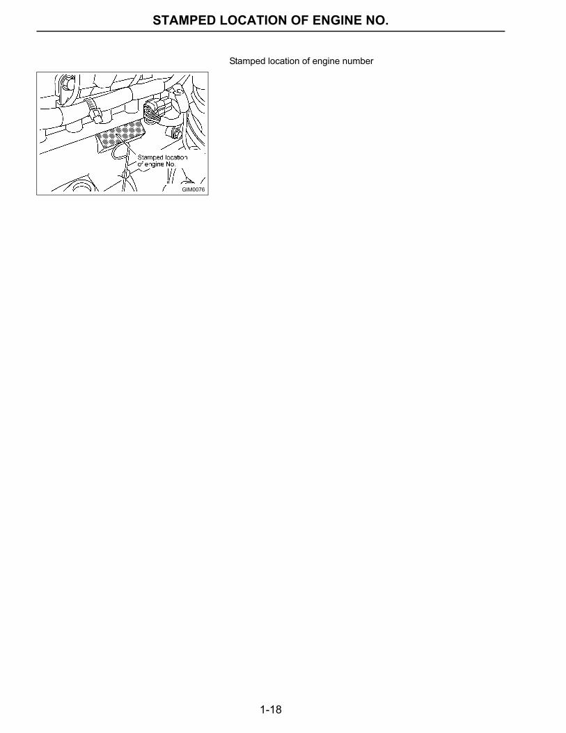
STAMPED LOCATION OF ENGINE NO.Stamped location of engine number
GIM0076
1-19
TROUBLE SHOOTING
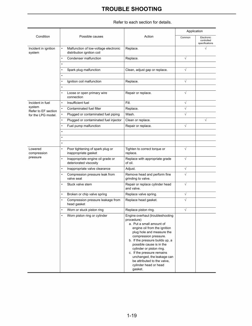
TROUBLE SHOOTING Refer to each section for details.
Condition Possible causes ActionApplication
Common Electronic controlled
specifications
Incident in ignition system
• Malfunction of low-voltage electronic distribution ignition coil
Replace. √
• Condenser malfunction Replace. √
•
• Spark plug malfunction Clean, adjust gap or replace. √
•
• Ignition coil malfunction Replace. √
•
• Loose or open primary wire connection
Repair or replace. √
Incident in fuel systemRefer to EF section for the LPG model.
• Insufficient fuel Fill. √
• Contaminated fuel filter Replace. √
• Plugged or contaminated fuel piping Wash. √
• Plugged or contaminated fuel injector Clean or replace. √
• Fuel pump malfunction Repair or replace. √
•
•
•
Lowered compression pressure
• Poor tightening of spark plug or inappropriate gasket
Tighten to correct torque or replace.
√
• Inappropriate engine oil grade or deteriorated viscosity
Replace with appropriate grade of oil.
√
• Inappropriate valve clearance Adjust. √
• Compression pressure leak from valve seat
Remove head and perform fine grinding to valve.
√
• Stuck valve stem Repair or replace cylinder head and valve.
√
• Broken or chip valve spring Replace valve spring. √
• Compression pressure leakage from head gasket
Replace head gasket. √
• Worn or stuck piston ring Replace piston ring. √
• Worn piston ring or cylinder Engine overhaul (troubleshooting procedure)
a. Put a small amount of engine oil from the ignition plug hole and measure the compression pressure.
b. If the pressure builds up, a possible cause is in the cylinder or piston ring.
c. If the pressure remains unchanged, the leakage can be attributed to the valve, cylinder head or head gasket.
1-20
TROUBLE SHOOTING
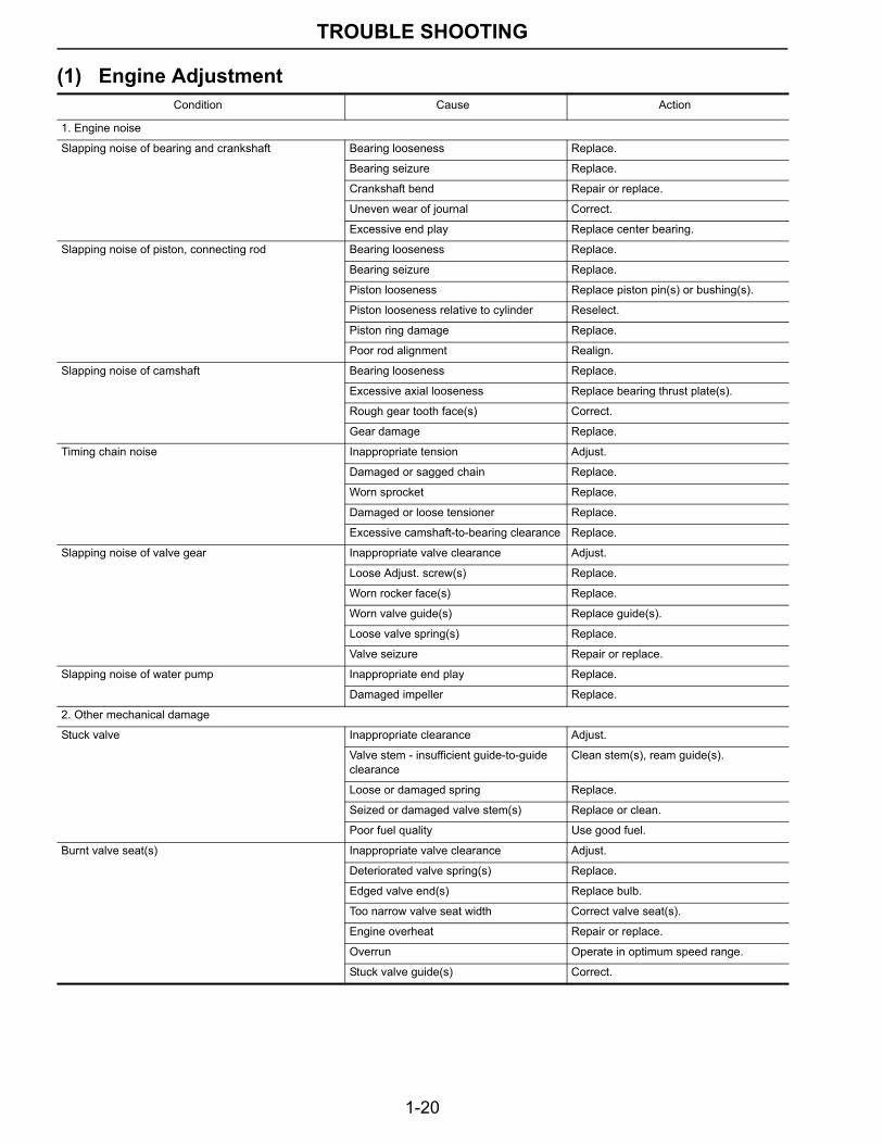
(1) Engine AdjustmentCondition Cause Action
1. Engine noise
Slapping noise of bearing and crankshaft Bearing looseness Replace.
Bearing seizure Replace.
Crankshaft bend Repair or replace.
Uneven wear of journal Correct.
Excessive end play Replace center bearing.
Slapping noise of piston, connecting rod Bearing looseness Replace.
Bearing seizure Replace.
Piston looseness Replace piston pin(s) or bushing(s).
Piston looseness relative to cylinder Reselect.
Piston ring damage Replace.
Poor rod alignment Realign.
Slapping noise of camshaft Bearing looseness Replace.
Excessive axial looseness Replace bearing thrust plate(s).
Rough gear tooth face(s) Correct.
Gear damage Replace.
Timing chain noise Inappropriate tension Adjust.
Damaged or sagged chain Replace.
Worn sprocket Replace.
Damaged or loose tensioner Replace.
Excessive camshaft-to-bearing clearance Replace.
Slapping noise of valve gear Inappropriate valve clearance Adjust.
Loose Adjust. screw(s) Replace.
Worn rocker face(s) Replace.
Worn valve guide(s) Replace guide(s).
Loose valve spring(s) Replace.
Valve seizure Repair or replace.
Slapping noise of water pump Inappropriate end play Replace.
Damaged impeller Replace.
2. Other mechanical damage
Stuck valve Inappropriate clearance Adjust.
Valve stem - insufficient guide-to-guide clearance
Clean stem(s), ream guide(s).
Loose or damaged spring Replace.
Seized or damaged valve stem(s) Replace or clean.
Poor fuel quality Use good fuel.
Burnt valve seat(s) Inappropriate valve clearance Adjust.
Deteriorated valve spring(s) Replace.
Edged valve end(s) Replace bulb.
Too narrow valve seat width Correct valve seat(s).
Engine overheat Repair or replace.
Overrun Operate in optimum speed range.
Stuck valve guide(s) Correct.
1-21
TROUBLE SHOOTING
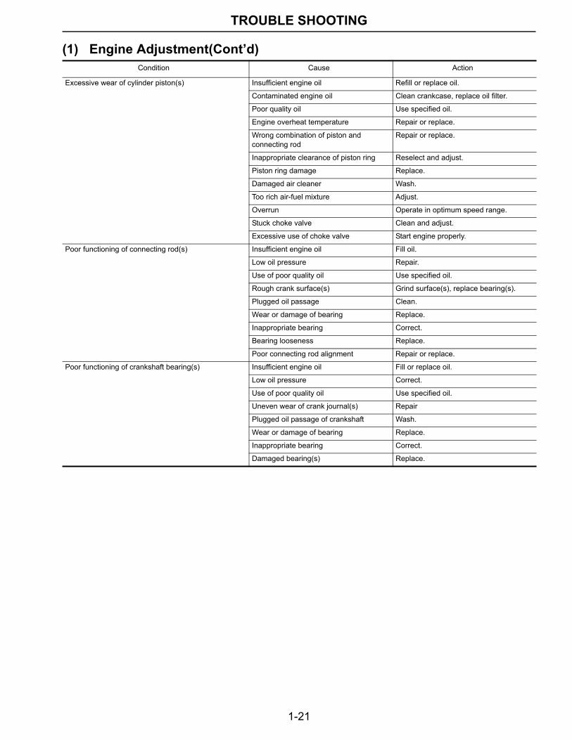
Excessive wear of cylinder piston(s) Insufficient engine oil Refill or replace oil.
Contaminated engine oil Clean crankcase, replace oil filter.
Poor quality oil Use specified oil.
Engine overheat temperature Repair or replace.
Wrong combination of piston and connecting rod
Repair or replace.
Inappropriate clearance of piston ring Reselect and adjust.
Piston ring damage Replace.
Damaged air cleaner Wash.
Too rich air-fuel mixture Adjust.
Overrun Operate in optimum speed range.
Stuck choke valve Clean and adjust.
Excessive use of choke valve Start engine properly.
Poor functioning of connecting rod(s) Insufficient engine oil Fill oil.
Low oil pressure Repair.
Use of poor quality oil Use specified oil.
Rough crank surface(s) Grind surface(s), replace bearing(s).
Plugged oil passage Clean.
Wear or damage of bearing Replace.
Inappropriate bearing Correct.
Bearing looseness Replace.
Poor connecting rod alignment Repair or replace.
Poor functioning of crankshaft bearing(s) Insufficient engine oil Fill or replace oil.
Low oil pressure Correct.
Use of poor quality oil Use specified oil.
Uneven wear of crank journal(s) Repair
Plugged oil passage of crankshaft Wash.
Wear or damage of bearing Replace.
Inappropriate bearing Correct.
Damaged bearing(s) Replace.
(1) Engine Adjustment(Cont’d)Condition Cause Action
1-22
TROUBLE SHOOTING
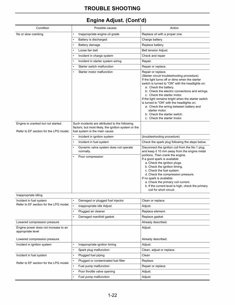
Engine Adjust. (Cont’d)Condition Possible causes Action
No or slow cranking • Inappropriate engine oil grade Replace oil with a proper one.
• Battery is discharged Charge battery.
• Battery damage Replace battery.
• Loose fan belt Belt tension Adjust.
• Incident in charge system Check and repair
• Incident in starter system wiring Repair.
• Starter switch malfunction Repair or replace.
• Starter motor malfunction Repair or replace.(Starter circuit troubleshooting procedure)If the light turns off or dims when the starter switch is turned to "ON" with the headlights on:
a: Check the battery.b: Check the electric connections and wirings.c: Check the starter motor.
If the light remains bright when the starter switch is turned to "ON" with the headlights on:
a: Check the wiring between battery and starter motor.
b: Check the starter switch.c: Check the starter motor.
Engine is cranked but not started.
Refer to EF section for the LPG model.
Such incidents are attributed to the following factors, but most likely, the ignition system or the fuel system is the main cause.
• Incident in ignition system (troubleshooting procedure)
• Incident in fuel system Check the spark plug following the steps below.
• Dynamic valve system does not operate normally.
Disconnect the ignition coil from the No.1 plug and keep it 10 mm away from the engine metal portions. Then crank the engine.If a good spark is available:
a. Check the ignition plugs.b. Check the ignition timing.c. Check the fuel system.d. Check the compression pressure.
If no spark is available:a. Check the primary coil current.b. If the current level is high, check the primary
coil for short circuit.
• Poor compression
Inappropriate idling
Incident in fuel systemRefer to EF section for the LPG model.
• Damaged or plugged fuel injector Clean or replace.
• Inappropriate idle Adjust. Adjust.
• Plugged air cleaner Replace element.
• Damaged manifold gasket Replace gasket
Lowered compression pressure Already described.
Engine power does not increase to an appropriate level
Lowered compression pressure
Adjust.
Already described.
Incident in ignition system • Inappropriate ignition timing Adjust.
• Spark plug malfunction Clean, adjust or replace.
Incident in fuel system
Refer to EF section for the LPG model.
• Plugged fuel piping Clean
• Plugged or contaminated fuel filter Replace.
• Fuel pump malfunction Repair or replace
• Poor throttle valve opening Adjust.
• Fuel pump malfunction Adjust.
1-23
TROUBLE SHOOTING
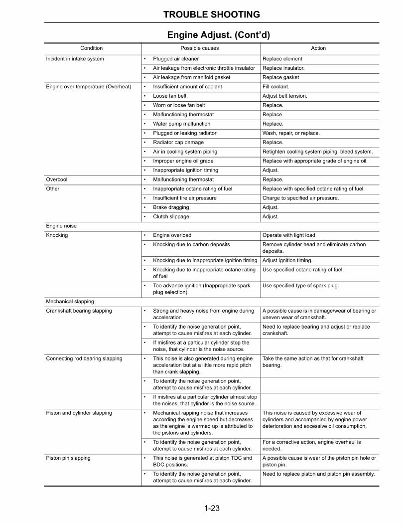
Incident in intake system • Plugged air cleaner Replace element
• Air leakage from electronic throttle insulator Replace insulator.
• Air leakage from manifold gasket Replace gasket
Engine over temperature (Overheat) • Insufficient amount of coolant Fill coolant.
• Loose fan belt. Adjust belt tension.
• Worn or loose fan belt Replace.
• Malfunctioning thermostat Replace.
• Water pump malfunction Replace.
• Plugged or leaking radiator Wash, repair, or replace.
• Radiator cap damage Replace.
• Air in cooling system piping Retighten cooling system piping, bleed system.
• Improper engine oil grade Replace with appropriate grade of engine oil.
• Inappropriate ignition timing Adjust.
Overcool • Malfunctioning thermostat Replace.
Other • Inappropriate octane rating of fuel Replace with specified octane rating of fuel.
• Insufficient tire air pressure Charge to specified air pressure.
• Brake dragging Adjust.
• Clutch slippage Adjust.
Engine noise
Knocking • Engine overload Operate with light load
• Knocking due to carbon deposits Remove cylinder head and eliminate carbon deposits.
• Knocking due to inappropriate ignition timing Adjust ignition timing.
• Knocking due to inappropriate octane rating of fuel
Use specified octane rating of fuel.
• Too advance ignition (Inappropriate spark plug selection)
Use specified type of spark plug.
Mechanical slapping
Crankshaft bearing slapping • Strong and heavy noise from engine during acceleration
A possible cause is in damage/wear of bearing or uneven wear of crankshaft.
• To identify the noise generation point, attempt to cause misfires at each cylinder.
Need to replace bearing and adjust or replace crankshaft.
• If misfires at a particular cylinder stop the noise, that cylinder is the noise source.
Connecting rod bearing slapping • This noise is also generated during engine acceleration but at a little more rapid pitch than crank slapping.
Take the same action as that for crankshaft bearing.
• To identify the noise generation point, attempt to cause misfires at each cylinder.
• If misfires at a particular cylinder almost stop the noises, that cylinder is the noise source.
Piston and cylinder slapping • Mechanical rapping noise that increases according the engine speed but decreases as the engine is warmed up is attributed to the pistons and cylinders.
This noise is caused by excessive wear of cylinders and accompanied by engine power deterioration and excessive oil consumption.
• To identify the noise generation point, attempt to cause misfires at each cylinder.
For a corrective action, engine overhaul is needed.
Piston pin slapping • This noise is generated at piston TDC and BDC positions.
A possible cause is wear of the piston pin hole or piston pin.
• To identify the noise generation point, attempt to cause misfires at each cylinder.
Need to replace piston and piston pin assembly.
Engine Adjust. (Cont’d)Condition Possible causes Action
1-24
TROUBLE SHOOTING
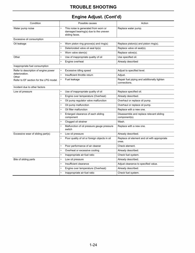
Water pump noise • This noise is generated from worn or damaged bearing(s) due to the uneven sliding faces.
Replace water pump.
Excessive oil consumption
Oil leakage • Worn piston ring groove(s) and ring(s) Replace piston(s) and piston ring(s).
• Deteriorated valve oil seal lip(s) Replace valve oil seal(s).
• Worn valve stem(s) Replace valve(s).
Other • Use of inappropriate quality of oil Use specified oil.
• Engine overheat Already described
Inappropriate fuel consumption
Refer to description of engine power deterioration.OtherRefer to EF section for the LPG model.
• Excessive idling speed Adjust to specified level.
• Insufficient throttle return Adjust.
• Fuel leakage Repair fuel piping and additionally tighten connections.
Incident due to other factors
Low oil pressure • Use of inappropriate quality of oil Replace specified oil.
• Engine over temperature (Overheat) Already described.
• Oil pump regulator valve malfunction Overhaul or replace oil pump.
• Oil pump malfunction Overhaul or replace oil pump.
• Oil filter malfunction Replace with a new one.
• Enlarged clearance of each sliding component
Disassemble and replace relevant sliding component(s).
• Clogged oil strainer Wash.
• Malfunction of oil pressure gauge pressure switch
Replace with a new one.
Excessive wear of sliding part(s) • Low oil pressure Already described.
• Poor quality of oil or foreign objects in oil Replace oil element and oil with appropriate ones.
• Poor performance of air cleaner Check element.
• Overheat or excessive cooling Already described.
• Inappropriate air-fuel ratio Check fuel system.
Bite of sliding parts • Low oil pressure Already described.
• Insufficient clearance Adjust clearance to specified value.
• Engine over temperature (Overheat) Already described.
• Inappropriate air-fuel ratio Check fuel system.
Engine Adjust. (Cont’d)Condition Possible causes Action
1-25
TROUBLE SHOOTING
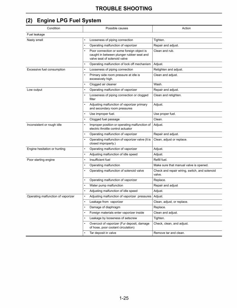
(2) Engine LPG Fuel System Condition Possible causes Action
Fuel leakage
Nasty smell • Looseness of piping connection Tighten.
• Operating malfunction of vaporizer Repair and adjust.
• Poor connection or some foreign object is caught in between plunger rubber seat and valve seat of solenoid valve
Clean and rub.
• Operating malfunction of lock off mechanism Adjust.
Excessive fuel consumption • Looseness of piping connection Retighten and adjust.
• Primary side room pressure at idle is excessively high.
Clean and adjust.
• Clogged air cleaner Wash.
Low output • Operating malfunction of vaporizer Repair and adjust.
• Looseness of piping connection or clogged filter
Clean and retighten.
• Adjusting malfunction of vaporizer primary and secondary room pressures
Adjust.
• Use improper fuel. Use proper fuel.
• Clogged fuel passage Clean.
Inconsistent or rough idle • Improper position or operating malfunction of electric throttle control actuator
Adjust.
• Operating malfunction of vaporizer Repair and adjust.
• Operating malfunction of vaporizer valve (It is closed improperly.)
Clean, adjust or replace.
Engine hesitation or hunting • Operating malfunction of vaporizer Adjust.
• Adjusting malfunction of idle speed Adjust.
Poor starting engine • Insufficient fuel Refill fuel.
• Operating malfunction Make sure that manual valve is opened.
• Operating malfunction of solenoid valve Check and repair wiring, switch, and solenoid valve.
• Operating malfunction of vaporizer Replace.
• Water pump malfunction Repair and adjust
• Adjusting malfunction of idle speed Adjust.
Operating malfunction of vaporizer • Adjusting malfunction of vaporizer pressures Adjust.
• Leakage from vaporizer Clean, adjust, or replace.
• Damage of diaphragm Replace.
• Foreign materials enter vaporizer inside Clean and adjust.
• Leakage by looseness of setscrew Tighten.
• Overcool of vaporizer (Fur deposit, damage of hose, poor coolant circulation)
Check, clean, and adjust.
• Tar deposit in valve Remove tar and clean.