general hardietrim boards products description hardie/trim/james... · 43 hardietrim® boards...
TRANSCRIPT
43
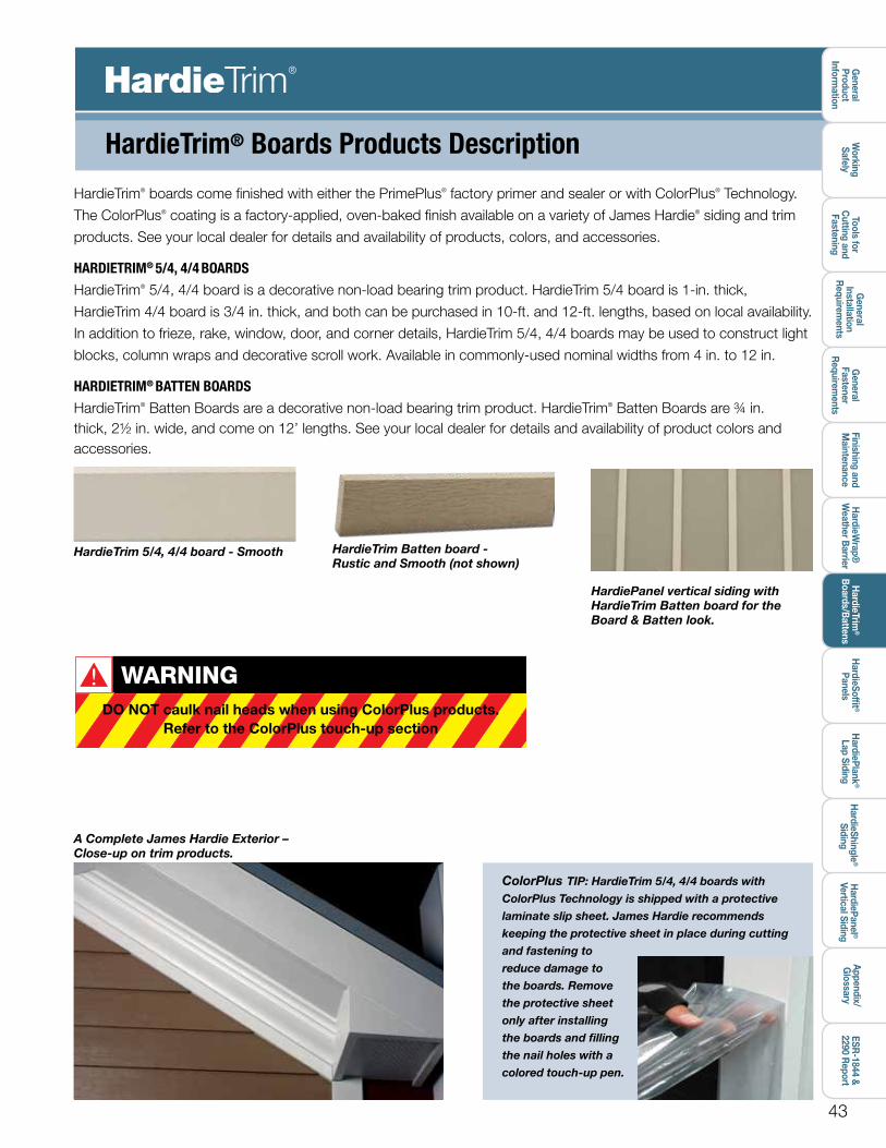
HardieTrim® Boards Products Description
HardieTrim® boards come finished with either the PrimePlus® factory primer and sealer or with ColorPlus® Technology.
The ColorPlus® coating is a factory-applied, oven-baked finish available on a variety of James Hardie® siding and trim
products. See your local dealer for details and availability of products, colors, and accessories.
HARDIETRIM® 5/4, 4/4 BOARDS
HardieTrim® 5/4, 4/4 board is a decorative non-load bearing trim product. HardieTrim 5/4 board is 1-in. thick,
HardieTrim 4/4 board is 3/4 in. thick, and both can be purchased in 10-ft. and 12-ft. lengths, based on local availability.
In addition to frieze, rake, window, door, and corner details, HardieTrim 5/4, 4/4 boards may be used to construct light
blocks, column wraps and decorative scroll work. Available in commonly-used nominal widths from 4 in. to 12 in.
HARDIETRIM® BATTEN BOARDS
HardieTrim® Batten Boards are a decorative non-load bearing trim product. HardieTrim® Batten Boards are ¾ in. thick, 2½ in. wide, and come on 12’ lengths. See your local dealer for details and availability of product colors and accessories.
HardieTrim 5/4, 4/4 board - Smooth HardieTrim Batten board - Rustic and Smooth (not shown)
A Complete James Hardie Exterior – Close-up on trim products.
HardiePanel vertical siding with HardieTrim Batten board for the Board & Batten look.
ColorPlus TIP: HardieTrim 5/4, 4/4 boards with
ColorPlus Technology is shipped with a protective
laminate slip sheet. James Hardie recommends
keeping the protective sheet in place during cutting
and fastening to
reduce damage to
the boards. Remove
the protective sheet
only after installing
the boards and filling
the nail holes with a
colored touch-up pen.
General
Product Inform
ation
Working
SafelyTools for
Cutting and
Fastening
General
Installation R
equirements
General
Fastener R
equirements
Finishing and M
aintenanceH
ardieTrim®
Boards/B
attensH
ardieWrap®
Weather B
arrierH
ardieSoffit ®
PanelsH
ardiePlank®
Lap SidingH
ardieShingle®
SidingH
ardiePanel ®
Vertical SidingAppendix/G
lossaryESR
-1844 &2290 R
eport
DO NOT caulk nail heads when using ColorPlus products. Refer to the ColorPlus touch-up section
! WARNING
44
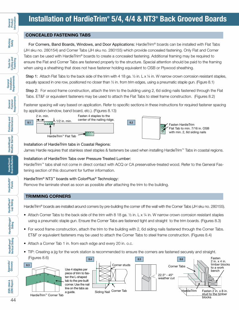
For Corners, Band Boards, Windows, and Door Applications: HardieTrim® boards can be installed with Flat Tabs
(JH sku no. 280154) and Corner Tabs (JH sku no. 280155) which provide concealed fastening. Only Flat and Corner
Tabs can be used with HardieTrim® boards to create a concealed fastening. Additional framing may be required to
ensure the Flat and Corner Tabs are fastened properly to the structure. Special attention should be paid to the framing
when using a sheathing that does not have fastener holding equivalent to OSB or Plywood sheathing.
Step 1: Attach Flat Tabs to the back side of the trim with 4 18 ga. ½ in. L x ¼ in. W narrow crown corrosion resistant staples,
equally spaced in one row, positioned no closer than ½ in. from trim edges, using a pneumatic staple gun. (Figure 8.1)
Step 2: For wood frame construction, attach the trim to the building using 2, 6d siding nails fastened through the Flat
Tabs. ET&F or equivalent fasteners may be used to attach the Flat Tabs to steel frame construction. (Figures 8.2)
Fastener spacing will vary based on application. Refer to specific sections in these instructions for required fastener spacing
by application (window, band board, etc.). (Figures 8.13)
Installation of HardieTrim tabs in Coastal Regions:
James Hardie requires that stainless steel staples & fasteners be used when installing HardieTrim™ Tabs in coastal regions.
Installation of HardieTrim Tabs over Pressure Treated Lumber:
HardieTrim™ tabs shall not come in direct contact with ACQ or CA preservative-treated wood. Refer to the General Fas-
tening section of this document for further information.
HardieTrim® NT3™ boards with ColorPlus® Technology:
Remove the laminate sheet as soon as possible after attaching the trim to the building.
HardieTrim® boards are installed around corners by pre-building the corner off the wall with the Corner Tabs (JH sku no. 280155).
• Attach Corner Tabs to the back side of the trim with 8 18 ga. ½ in. L x ¼ in. W narrow crown corrosion resistant staples
using a pneumatic staple gun. Ensure the Corner Tabs are fastened tight and straight to the trim boards. (Figures 8.3)
• For wood frame construction, attach the trim to the building with 2, 6d siding nails fastened through the Corner Tabs.
ET&F or equivalent fasteners may be used to attach the Corner Tabs to steel frame construction. (Figures 8.4)
• Attach a Corner Tab 1 in. from each edge and every 20 in. o.c.
• TIP: Creating a jig for the work station is recommended to ensure the corners are fastened securely and straight.
(Figures 8.6)
Installation of HardieTrim® 5/4, 4/4 & NT3® Back Grooved Boards
CONCEALED FASTENING TABS
TRIMMING CORNERS
2 in. min.
1/2 in. min.
Fasten 4 staples to the center of the nailing ridge.
Fasten HardieTrimFlat Tab to min. 7/16 in. OSB with min. 2, 6d siding nails
Use 4 staples per piece of trim to fas-ten the L-shaped tab to the pre-built corner. Use the nail line on the tabs as a guide.
HardieTrim™ Flat Tab
HardieTrim™ Corner Tab
Corner studs
Corner Tab
22.5º - 45ºweather cut
Fasten 2 in. x 4 in. timber blocksto a work bench
Fasten 2 in. x 8 in. stud to the timber blocks
HardieTrim
Corner Tabs
Siding Nail
8.1 8.2
8.3
8.4 8.5 8.6
Gen
eral
Pr
oduc
t In
form
atio
n
Wor
king
Sa
fely
Tool
s fo
r C
uttin
g an
dFa
sten
ing
Gen
eral
In
stal
latio
n R
equi
rem
ents
Gen
eral
Fa
sten
er
Req
uire
men
ts
Fini
shin
g an
d M
aint
enan
ceH
ardi
eTrim
® B
oard
s/B
atte
nsH
ardi
eWra
p® W
eath
er B
arrie
rH
ardi
eSof
fit®
Pan
els
Har
dieP
lank
®
Lap
Sid
ing
Har
dieS
hing
le®
Sid
ing
Har
dieP
anel
®
Ver
tical
Sid
ing
Appe
ndix
/G
loss
ary
ESR
-184
4 &
2290
Rep
ort
45
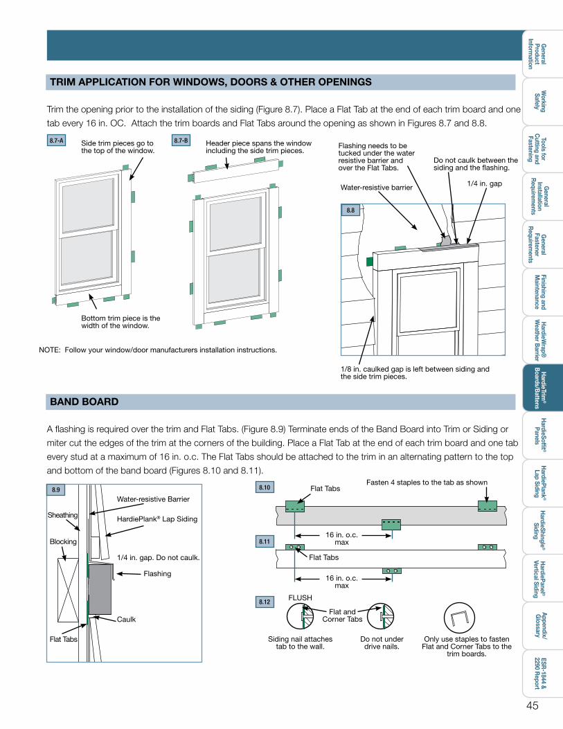
TRIM APPLICATION FOR WINDOWS, DOORS & OTHER OPENINGS
BAND BOARD
Trim the opening prior to the installation of the siding (Figure 8.7). Place a Flat Tab at the end of each trim board and one
tab every 16 in. OC. Attach the trim boards and Flat Tabs around the opening as shown in Figures 8.7 and 8.8.
A flashing is required over the trim and Flat Tabs. (Figure 8.9) Terminate ends of the Band Board into Trim or Siding or
miter cut the edges of the trim at the corners of the building. Place a Flat Tab at the end of each trim board and one tab
every stud at a maximum of 16 in. o.c. The Flat Tabs should be attached to the trim in an alternating pattern to the top
and bottom of the band board (Figures 8.10 and 8.11).
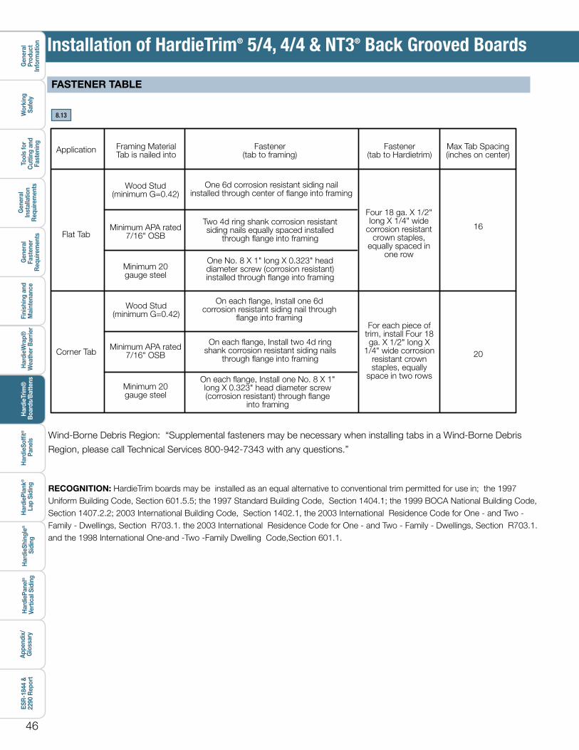
Application Framing MaterialTab is nailed into
Flat Tab
Wood Stud(minimum G=0.42)
Minimum APA rated7/16" OSB
Corner TabMinimum APA rated
7/16" OSB
Minimum 20gauge steel
Minimum 20gauge steel
Wood Stud(minimum G=0.42)
Fastener(tab to Hardietrim)
Max Tab Spacing(inches on center)
Four 18 ga. X 1/2" long X 1/4" wide
corrosion resistant crown staples,
equally spaced in one row
16
For each piece of trim, install Four 18 ga. X 1/2" long X
1/4" wide corrosion resistant crown staples, equally
space in two rows
20
Fastener(tab to framing)
One 6d corrosion resistant siding nailinstalled through center of flange into framing
Two 4d ring shank corrosion resistantsiding nails equally spaced installed
through flange into framing
One No. 8 X 1" long X 0.323" headdiameter screw (corrosion resistant)installed through flange into framing
On each flange, Install one 6dcorrosion resistant siding nail through
flange into framing
On each flange, Install two 4d ringshank corrosion resistant siding nails
through flange into framing
On each flange, Install one No. 8 X 1"long X 0.323" head diameter screw(corrosion resistant) through flange
into framing
8.7-A 8.7-B
8.8
8.9 8.10
8.11
8.12
Side trim pieces go tothe top of the window.
Header piece spans the window including the side trim pieces.
Flashing needs to be tucked under the water resistive barrier and over the Flat Tabs.
Do not caulk between the siding and the flashing.
Water-resistive barrier
Water-resistive BarrierFlat Tabs
Flat Tabs
FLUSH
Siding nail attaches tab to the wall.
Do not underdrive nails.
Only use staples to fasten Flat and Corner Tabs to the
trim boards.
16 in. o.c. max
16 in. o.c. max
Fasten 4 staples to the tab as shown
HardiePlank® Lap Siding
1/4 in. gap. Do not caulk.
Flashing
Caulk
Flat Tabs
Blocking
Sheathing
1/8 in. caulked gap is left between siding and the side trim pieces.
1/4 in. gap
Bottom trim piece is the width of the window.
NOTE: Follow your window/door manufacturers installation instructions.
Flat andCorner Tabs
General
Product Inform
ation
Working
SafelyTools for
Cutting and
Fastening
General
Installation R
equirements
General
Fastener R
equirements
Finishing and M
aintenanceH
ardieTrim®
Boards/B
attensH
ardieWrap®
Weather B
arrierH
ardieSoffit ®
PanelsH
ardiePlank®
Lap SidingH
ardieShingle®
SidingH
ardiePanel ®
Vertical SidingAppendix/G
lossaryESR
-1844 &2290 R
eport
46
FASTENER TABLE
Wind-Borne Debris Region: “Supplemental fasteners may be necessary when installing tabs in a Wind-Borne Debris
Region, please call Technical Services 800-942-7343 with any questions.”
RECOGNITION: HardieTrim boards may be installed as an equal alternative to conventional trim permitted for use in; the 1997 Uniform Building Code, Section 601.5.5; the 1997 Standard Building Code, Section 1404.1; the 1999 BOCA National Building Code, Section 1407.2.2; 2003 International Building Code, Section 1402.1, the 2003 International Residence Code for One - and Two - Family - Dwellings, Section R703.1. the 2003 International Residence Code for One - and Two - Family - Dwellings, Section R703.1. and the 1998 International One-and -Two -Family Dwelling Code,Section 601.1.
Application Framing MaterialTab is nailed into
Flat Tab
Wood Stud(minimum G=0.42)
Minimum APA rated7/16" OSB
Corner TabMinimum APA rated
7/16" OSB
Minimum 20gauge steel
Minimum 20gauge steel
Wood Stud(minimum G=0.42)
Fastener(tab to Hardietrim)
Max Tab Spacing(inches on center)
Four 18 ga. X 1/2" long X 1/4" wide
corrosion resistant crown staples,
equally spaced in one row
16
For each piece of trim, install Four 18 ga. X 1/2" long X
1/4" wide corrosion resistant crown staples, equally
space in two rows
20
Fastener(tab to framing)
One 6d corrosion resistant siding nailinstalled through center of flange into framing
Two 4d ring shank corrosion resistantsiding nails equally spaced installed
through flange into framing
One No. 8 X 1" long X 0.323" headdiameter screw (corrosion resistant)installed through flange into framing
On each flange, Install one 6dcorrosion resistant siding nail through
flange into framing
On each flange, Install two 4d ringshank corrosion resistant siding nails
through flange into framing
On each flange, Install one No. 8 X 1"long X 0.323" head diameter screw(corrosion resistant) through flange
into framing
8.13
Gen
eral
Pr
oduc
t In
form
atio
n
Wor
king
Sa
fely
Tool
s fo
r C
uttin
g an
dFa
sten
ing
Gen
eral
In
stal
latio
n R
equi
rem
ents
Gen
eral
Fa
sten
er
Req
uire
men
ts
Fini
shin
g an
d M
aint
enan
ceH
ardi
eTrim
® B
oard
s/B
atte
nsH
ardi
eWra
p® W
eath
er B
arrie
rH
ardi
eSof
fit®
Pan
els
Har
dieP
lank
®
Lap
Sid
ing
Har
dieS
hing
le®
Sid
ing
Har
dieP
anel
®
Ver
tical
Sid
ing
Appe
ndix
/G
loss
ary
ESR
-184
4 &
2290
Rep
ort
Installation of HardieTrim® 5/4, 4/4 & NT3® Back Grooved Boards
47
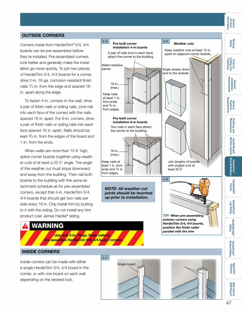
OUTSIDE CORNERS
TIP: When pre-assembling exterior corners using HardieTrim 5/4, 4/4 boards, position the finish nailer parallel with the trim
Single board
INSIDE CORNERS
Inside corners can be made with either
a single HardieTrim 5/4, 4/4 board in the
corner, or with one board on each wall
depending on the desired look.
Keep weather cuts at least 12 in. apart on adjacent corner boards.
Keep nails at least 1 in. from ends and 3/4 in. from edges.
Angle slopes down and to the outside.
Join lengths of boardswith angled cuts at least 22.5˚
Two nails in each face attachthe corner to the building.
Water-resistive barrier
16-in. (max.)
Keep nails at least 1 in. from ends and 3/4 in. from edges.
Pre-built corner installation 4-in boards
Weather cuts
A pair of nails (one in each face) attach the corner to the building.
Pre-built corner installation 6-in boards
16-in. (max.)
Corners made from HardieTrim® 5/4, 4/4
boards can be pre-assembled before
they’re installed. Pre-assembled corners
look better and generally make the instal-
lation go more quickly. To join two pieces
of HardieTrim 5/4, 4/4 boards for a corner,
drive 2-in. 16 ga. corrosion-resistant finish
nails 1/2 in. from the edge and spaced 16-
in. apart along the edge.
To fasten 4-in. corners to the wall, drive
a pair of finish nails or siding nails, (one nail
into each face of the corner) with the nails
spaced 16 in. apart. For 6-in. corners, drive
a pair of finish nails or siding nails into each
face spaced 16 in. apart. Nails should be
kept 3/4 in. from the edges of the board and
1-in. from the ends.
When walls are more than 10 ft. high,
splice corner boards together using weath-
er cuts of at least a 22.5° angle. The angle
of the weather cut must slope downward
and away from the building. Then nail both
boards to the building with the same at-
tachment schedule as for pre-assembled
corners, except that 4-in. HardieTrim 5/4,
4/4 boards that should get two nails per
side every 16 in. Only install trim by butting
to it with the siding. Do not install any trim
product over James Hardie® siding.
NOTE: All weather cut joints should be touched up prior to installation.
8.14 8.15
8.16
8.17
WARNINGUse only 2-in. 16-ga. finish nails to
pre-assemble HardieTrim 5/4, 4/4 board corners.
!
General
Product Inform
ation
Working
SafelyTools for
Cutting and
Fastening
General
Installation R
equirements
General
Fastener R
equirements
Finishing and M
aintenanceH
ardieTrim®
Boards/B
attensH
ardieWrap®
Weather B
arrierH
ardieSoffit ®
PanelsH
ardiePlank®
Lap SidingH
ardieShingle®
SidingH
ardiePanel ®
Vertical SidingAppendix/G
lossaryESR
-1844 &2290 R
eport
48
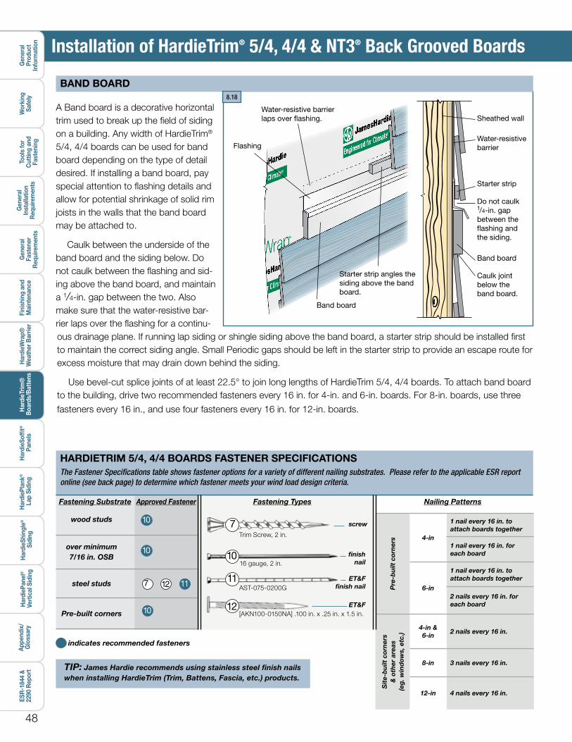
A Band board is a decorative horizontal trim used to break up the field of siding on a building. Any width of HardieTrim®
5/4, 4/4 boards can be used for band board depending on the type of detail desired. If installing a band board, pay special attention to flashing details and allow for potential shrinkage of solid rim joists in the walls that the band board may be attached to.
Caulk between the underside of the band board and the siding below. Do not caulk between the flashing and sid-ing above the band board, and maintain a 1/4-in. gap between the two. Also make sure that the water-resistive bar-rier laps over the flashing for a continu-
Water-resistive barrier
Band board
Starter strip angles the siding above the band board.
Water-resistive barrier laps over flashing.
Band board
Starter strip
Do not caulk 1/4-in. gap between the flashing and the siding.
Caulk joint below the band board.
Sheathed wall
Flashing
BAND BOARD
Pre
-bu
ilt c
orn
ers 4-in
1 nail every 16 in. to attach boards together
1 nail every 16 in. for each board
6-in
1 nail every 16 in. to attach boards together
2 nails every 16 in. for each board
Sit
e-b
uilt
cor
ner
s &
oth
er a
reas
(eg
. win
dow
s, e
tc.)
4-in & 6-in
2 nails every 16 in.
8-in 3 nails every 16 in.
12-in 4 nails every 16 in.
wood studs
over minimum 7/16 in. OSB
steel studs
Pre-built corners
HARDIETRIM 5/4, 4/4 BOARDS FASTENER SPECIFICATIONSThe Fastener Specifications table shows fastener options for a variety of different nailing substrates. Please refer to the applicable ESR report online (see back page) to determine which fastener meets your wind load design criteria.
indicates recommended fasteners
7Trim Screw, 2 in.
screw
1016 gauge, 2 in.
finish nail
11AST-075-0200G
ET&F finish nail
[AKN100-0150NA] .100 in. x .25 in. x 1.5 in.12 ET&F
7 12
10
10
10
11
Fastening Substrate Fastening Types Nailing PatternsApproved Fastener
TIP: James Hardie recommends using stainless steel finish nails when installing HardieTrim (Trim, Battens, Fascia, etc.) products.
8.18
ous drainage plane. If running lap siding or shingle siding above the band board, a starter strip should be installed first to maintain the correct siding angle. Small Periodic gaps should be left in the starter strip to provide an escape route for excess moisture that may drain down behind the siding.
Use bevel-cut splice joints of at least 22.5° to join long lengths of HardieTrim 5/4, 4/4 boards. To attach band board to the building, drive two recommended fasteners every 16 in. for 4-in. and 6-in. boards. For 8-in. boards, use three
fasteners every 16 in., and use four fasteners every 16 in. for 12-in. boards.
Gen
eral
Pr
oduc
t In
form
atio
n
Wor
king
Sa
fely
Tool
s fo
r C
uttin
g an
dFa
sten
ing
Gen
eral
In
stal
latio
n R
equi
rem
ents
Gen
eral
Fa
sten
er
Req
uire
men
ts
Fini
shin
g an
d M
aint
enan
ceH
ardi
eTrim
® B
oard
s/B
atte
nsH
ardi
eWra
p® W
eath
er B
arrie
rH
ardi
eSof
fit®
Pan
els
Har
dieP
lank
®
Lap
Sid
ing
Har
dieS
hing
le®
Sid
ing
Har
dieP
anel
®
Ver
tical
Sid
ing
Appe
ndix
/G
loss
ary
ESR
-184
4 &
2290
Rep
ort
Installation of HardieTrim® 5/4, 4/4 & NT3® Back Grooved Boards
49
1/4 in. gapWater-resistive barrier
1/8-in. caulked gap is left between siding and the side trim pieces.
Header piece spans the window including the side trim pieces.
Side trim pieces go to the top of the window.
Bottom trim piece is the width of the window.
Starter stripDo not caulk between the siding and the flashing.
Flashing
WINDOW AND DOOR TRIM
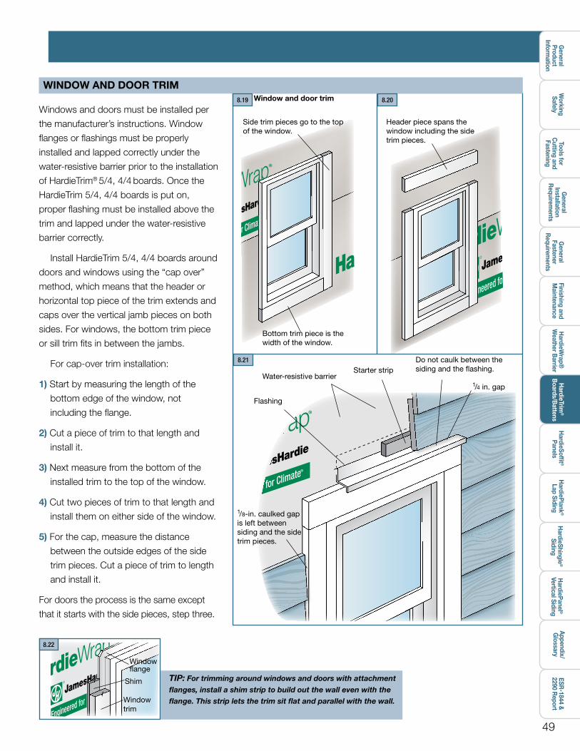
Windows and doors must be installed per
the manufacturer’s instructions. Window
flanges or flashings must be properly
installed and lapped correctly under the
water-resistive barrier prior to the installation
of HardieTrim® 5/4, 4/4 boards. Once the
HardieTrim 5/4, 4/4 boards is put on,
proper flashing must be installed above the
trim and lapped under the water-resistive
barrier correctly.
Install HardieTrim 5/4, 4/4 boards around
doors and windows using the “cap over”
method, which means that the header or
horizontal top piece of the trim extends and
caps over the vertical jamb pieces on both
sides. For windows, the bottom trim piece
or sill trim fits in between the jambs.
For cap-over trim installation:
1) Start by measuring the length of the
bottom edge of the window, not
including the flange.
2) Cut a piece of trim to that length and
install it.
3) Next measure from the bottom of the
installed trim to the top of the window.
4) Cut two pieces of trim to that length and
install them on either side of the window.
5) For the cap, measure the distance
between the outside edges of the side
trim pieces. Cut a piece of trim to length
and install it.
For doors the process is the same except
that it starts with the side pieces, step three.
Window and door trim
TIP: For trimming around windows and doors with attachment
flanges, install a shim strip to build out the wall even with the
flange. This strip lets the trim sit flat and parallel with the wall.
Shim
Window trim
Window flange
8.19 8.20
8.21
8.22
General
Product Inform
ation
Working
SafelyTools for
Cutting and
Fastening
General
Installation R
equirements
General
Fastener R
equirements
Finishing and M
aintenanceH
ardieTrim®
Boards/B
attensH
ardieWrap®
Weather B
arrierH
ardieSoffit ®
PanelsH
ardiePlank®
Lap SidingH
ardieShingle®
SidingH
ardiePanel ®
Vertical SidingAppendix/G
lossaryESR
-1844 &2290 R
eport
50
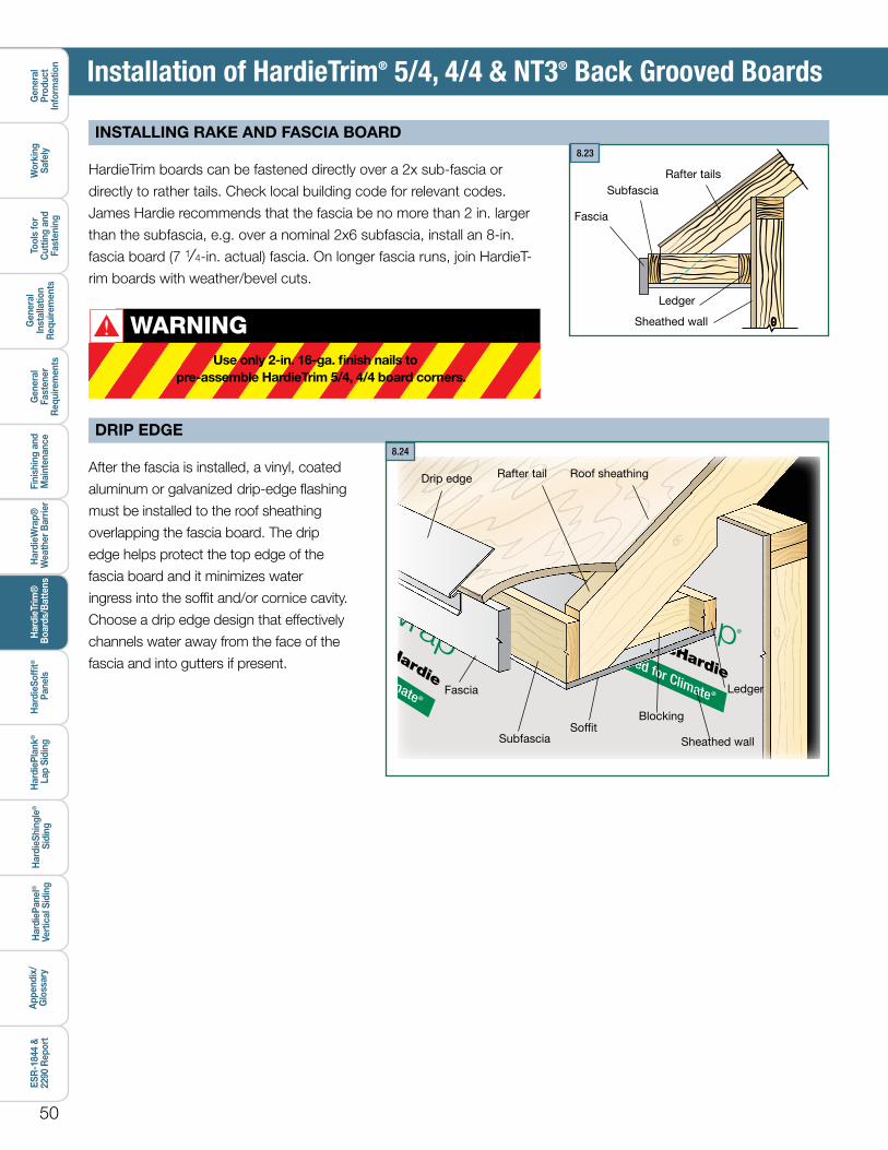
INSTALLING RAKE AND FASCIA BOARD
HardieTrim boards can be fastened directly over a 2x sub-fascia or
directly to rather tails. Check local building code for relevant codes.
James Hardie recommends that the fascia be no more than 2 in. larger
than the subfascia, e.g. over a nominal 2x6 subfascia, install an 8-in.
fascia board (7 1/4-in. actual) fascia. On longer fascia runs, join HardieT-
rim boards with weather/bevel cuts. Ledger
Fascia
SubfasciaRafter tails
Sheathed wall
DRIP EDGE
After the fascia is installed, a vinyl, coated
aluminum or galvanized drip-edge flashing
must be installed to the roof sheathing
overlapping the fascia board. The drip
edge helps protect the top edge of the
fascia board and it minimizes water
ingress into the soffit and/or cornice cavity.
Choose a drip edge design that effectively
channels water away from the face of the
fascia and into gutters if present.
Subfascia
Ledger
Rafter tail
Sheathed wallSoffit
Drip edge Roof sheathing
Fascia
Blocking
8.23
8.24
WARNINGUse only 2-in. 16-ga. finish nails to
pre-assemble HardieTrim 5/4, 4/4 board corners.
!
Gen
eral
Pr
oduc
t In
form
atio
n
Wor
king
Sa
fely
Tool
s fo
r C
uttin
g an
dFa
sten
ing
Gen
eral
In
stal
latio
n R
equi
rem
ents
Gen
eral
Fa
sten
er
Req
uire
men
ts
Fini
shin
g an
d M
aint
enan
ceH
ardi
eTrim
® B
oard
s/B
atte
nsH
ardi
eWra
p® W
eath
er B
arrie
rH
ardi
eSof
fit®
Pan
els
Har
dieP
lank
®
Lap
Sid
ing
Har
dieS
hing
le®
Sid
ing
Har
dieP
anel
®
Ver
tical
Sid
ing
Appe
ndix
/G
loss
ary
ESR
-184
4 &
2290
Rep
ort
Installation of HardieTrim® 5/4, 4/4 & NT3® Back Grooved Boards
51
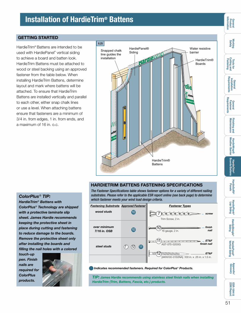
Installation of HardieTrim® Battens
GETTING STARTED
HardieTrim® Battens are intended to be used with HardiePanel® vertical siding to achieve a board and batten look. HardieTrim Battens must be attached to wood or steel backing using an approved fastener from the table below. When installing HardieTrim Battens, determine layout and mark where battens will be attached. To ensure that HardieTrim Battens are installed vertically and parallel to each other, either snap chalk lines or use a level. When attaching battens ensure that fasteners are a minimum of 3/4 in. from edges, 1 in. from ends, and a maximum of 16 in. o.c.
Snapped chalkline guides theinstallation
HardiePanel®Siding
Water resistivebarrier
HardieTrim®Boards
HardieTrim®Battens
wood studs
over minimum 7/16 in. OSB
steel studs
6d
Indicates recommended fasteners. Required for ColorPlus® Products.
7Trim Screw, 2 in.
screw
1016 gauge, 2 in.
finish nail
11AST-075-0200G
ET&F finish nail
[AKN100-0150NA] .100 in. x .25 in. x 1.5 in.12 ET&F
7 12 11
Fastening Substrate Fastener TypesApproved Fastener
ColorPlus® TIP:HardieTrim® Battens with ColorPlus® Technology are shipped with a protective laminate slip sheet. James Hardie recommends keeping the protective sheet in place during cutting and fastening to reduce damage to the boards. Remove the protective sheet only after installing the boards and filling the nail holes with a colored touch-up pen. Finish nails are required for ColorPlus products.
TIP: James Hardie recommends using stainless steel finish nails when installing HardieTrim (Trim, Battens, Fascia, etc.) products.
8.25
General
Product Inform
ation
Working
SafelyTools for
Cutting and
Fastening
General
Installation R
equirements
General
Fastener R
equirements
Finishing and M
aintenanceH
ardieTrim®
Boards/B
attensH
ardieWrap®
Weather B
arrierH
ardieSoffit ®
PanelsH
ardiePlank®
Lap SidingH
ardieShingle®
SidingH
ardiePanel ®
Vertical SidingAppendix/G
lossaryESR
-1844 &2290 R
eport
HARDIETRIM BATTENS FASTENING SPECIFICATIONSThe Fastener Specifications table shows fastener options for a variety of different nailing substrates. Please refer to the applicable ESR report online (see back page) to determine which fastener meets your wind load design criteria.
10
10
52
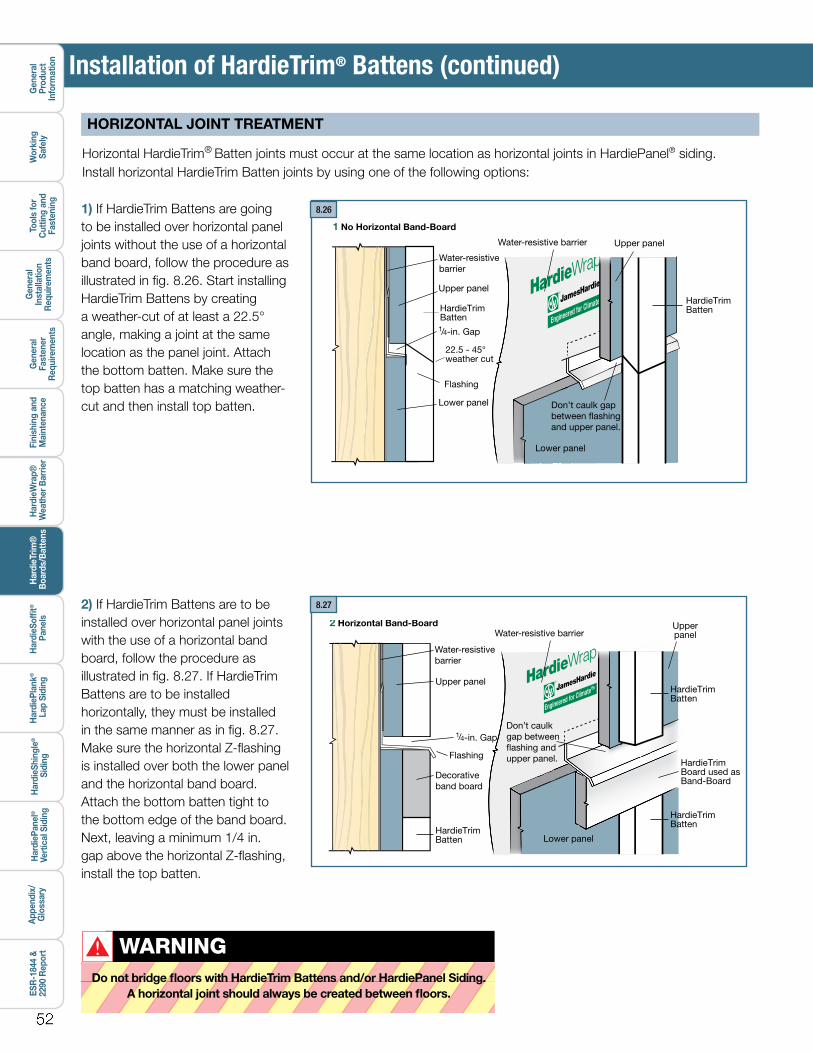
Horizontal HardieTrim® Batten joints must occur at the same location as horizontal joints in HardiePanel® siding.Install horizontal HardieTrim Batten joints by using one of the following options:
HORIZONTAL JOINT TREATMENT
Water-resistive barrier
Flashing
Upper panel
Lower panel
Decorative band board
Water-resistive barrier
Upper panel
1/4-in. Gap
Water-resistive barrier Upper panel
Lower panel
1 No Horizontal Band-Board
2 Horizontal Band-BoardWater-resistive barrier
HardieTrimBatten
22.5 - 45°weather cut
HardieTrim Board used as Band-Board
Flashing
1/4-in. Gap
Don’t caulk gapbetween flashingand upper panel.
Upperpanel
HardieTrimBatten
HardieTrimBatten
HardieTrimBatten
HardieTrimBatten
Don’
flupper panel.
t caulk gap between ashing and
Lower panel
1) If HardieTrim Battens are going to be installed over horizontal panel joints without the use of a horizontal band board, follow the procedure as illustrated in fig. 8.26. Start installing HardieTrim Battens by creating a weather-cut of at least a 22.5° angle, making a joint at the same location as the panel joint. Attach the bottom batten. Make sure the top batten has a matching weather-cut and then install top batten.
2) If HardieTrim Battens are to be installed over horizontal panel joints with the use of a horizontal band board, follow the procedure as illustrated in fig. 8.27. If HardieTrim Battens are to be installed horizontally, they must be installed in the same manner as in fig. 8.27. Make sure the horizontal Z-flashing is installed over both the lower panel and the horizontal band board. Attach the bottom batten tight to the bottom edge of the band board. Next, leaving a minimum 1/4 in. gap above the horizontal Z-flashing, install the top batten.
Water-resistive barrier
Flashing
Upper panel
Lower panel
Decorative band board
Water-resistive barrier
Upper panel
1/4-in. Gap
Water-resistive barrier Upper panel
Lower panel
1 No Horizontal Band-Board
2 Horizontal Band-BoardWater-resistive barrier
HardieTrimBatten
22.5 - 45°weather cut
HardieTrim Board used as Band-Board
Flashing
1/4-in. Gap
Don’t caulk gapbetween flashingand upper panel.
Upperpanel
HardieTrimBatten
HardieTrimBatten
HardieTrimBatten
HardieTrimBatten
Don’
flupper panel.
t caulk gap between ashing and
Lower panel
8.26
8.27
WARNINGDo not bridge floors with HardieTrim Battens and/or HardiePanel Siding.
A horizontal joint should always be created between floors.
!
Gen
eral
Pr
oduc
t In
form
atio
n
Wor
king
Sa
fely
Tool
s fo
r C
uttin
g an
dFa
sten
ing
Gen
eral
In
stal
latio
n R
equi
rem
ents
Gen
eral
Fa
sten
er
Req
uire
men
ts
Fini
shin
g an
d M
aint
enan
ceH
ardi
eTrim
® B
oard
s/B
atte
nsH
ardi
eWra
p® W
eath
er B
arrie
rH
ardi
eSof
fit®
Pan
els
Har
dieP
lank
®
Lap
Sid
ing
Har
dieS
hing
le®
Sid
ing
Har
dieP
anel
®
Ver
tical
Sid
ing
Appe
ndix
/G
loss
ary
ESR
-184
4 &
2290
Rep
ort
Installation of HardieTrim® Battens (continued)
53TR1510_P1/9 03/15
James Hardie products contain respirable crystalline silica, which is known to the State of California to cause cancer and is considered by IARC and NIOSH to be a cause of cancer from some occupational sources. Breathing excessive amounts of respirable silica dust can also cause a disabling and potentially fatal lung disease called silicosis, and has been linked with other diseases. Some studies suggest smoking may increase these risks. During installation or handling: (1) work in outdoor areas with ample ventilation; (2) use fiber cement shears for cutting or, where not feasible, use a HardieBlade saw blade and dust-reducing circular saw attached to a HEPA vacuum; (3) warn others in the immediate area; (4) wear a properly-fitted, NIOSH-approved dust mask or respirator (e.g. N-95) in accordance with applicable government regulations and manufacturer instructions to further limit respirable silica exposures. During clean-up, use HEPA vacuums or wet cleanup methods - never dry sweep. For further information, refer to our installation instructions and Material Safety Data Sheet available at www.jameshardie.com or by calling 1-800-9HARDIE (1-800-942-7343). FAILURE TO ADHERE TO OUR WARNINGS, MSDS, AND INSTALLATION INSTRUCTIONS MAY LEAD TO SERIOUS PERSONAL INJURY OR DEATH. SD050905
TABLE OF CONTENTS:
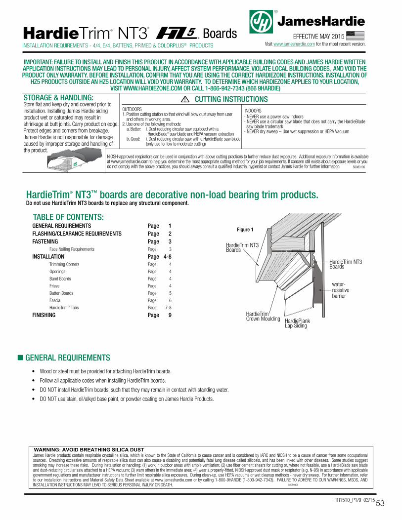
HardieTrim® NT3™ boards are decorative non-load bearing trim products.
INSTALLATION REQUIREMENTS - 4/4, 5/4, BATTENS, PRIMED & COLORPLUS® PRODUCTS Visit www.jameshardie.com for the most recent version.EFFECTIVE MAY 2015
OUTDOORS1. Position cutting station so that wind will blow dust away from user and others in working area.2. Use one of the following methods: a. Better: i. Dust reducing circular saw equipped with a HardieBlade® saw blade and HEPA vacuum extraction b. Good: i. Dust reducing circular saw with a HardieBlade saw blade (only use for low to moderate cutting)
INDOORS - NEVER use a power saw indoors - NEVER use a circular saw blade that does not carry the HardieBlade saw blade trademark- NEVER dry sweep – Use wet suppression or HEPA Vacuum
NIOSH-approved respirators can be used in conjunction with above cutting practices to further reduce dust exposures. Additional exposure information is available at www.jameshardie.com to help you determine the most appropriate cutting method for your job requirements. If concern still exists about exposure levels or you do not comply with the above practices, you should always consult a qualified industrial hygienist or contact James Hardie for further information. SD083105
CUTTING INSTRUCTIONSSTORAGE & HANDLING:
IMPORTANT: FAILURE TO INSTALL AND FINISH THIS PRODUCT IN ACCORDANCE WITH APPLICABLE BUILDING CODES AND JAMES HARDIE WRITTEN APPLICATION INSTRUCTIONS MAY LEAD TO PERSONAL INJURY, AFFECT SYSTEM PERFORMANCE, VIOLATE LOCAL BUILDING CODES, AND VOID THE PRODUCT ONLY WARRANTY. BEFORE INSTALLATION, CONFIRM THAT YOU ARE USING THE CORRECT HARDIEZONE INSTRUCTIONS. INSTALLATION OF
HZ5 PRODUCTS OUTSIDE AN HZ5 LOCATION WILL VOID YOUR WARRANTY. TO DETERMINE WHICH HARDIEZONE APPLIES TO YOUR LOCATION, VISIT WWW.HARDIEZONE.COM OR CALL 1-866-942-7343 (866 9HARDIE)
Store flat and keep dry and covered prior to installation. Installing James Hardie siding product wet or saturated may result in shrinkage at butt joints. Carry product on edge. Protect edges and corners from breakage. James Hardie is not responsible for damage caused by improper storage and handling ofthe product.
GENERAL REQUIREMENTS Page 1FLASHING/CLEARANCE REQUIREMENTS Page 2FASTENING Page 3 Face Nailing Requirements Page 3
INSTALLATION Page 4-8 Trimming Corners Page 4
Openings Page 4
Band Boards Page 4
Frieze Page 4
Batten Boards Page 5
Fascia Page 6
HardieTrim™ Tabs Page 7-8
FINISHING Page 9
• Wood or steel must be provided for attaching HardieTrim boards.
• Follow all applicable codes when installing HardieTrim boards.
• DO NOT install HardieTrim boards, such that they may remain in contact with standing water.
• DO NOT use stain, oil/alkyd base paint, or powder coating on James Hardie Products.
Do not use HardieTrim NT3 boards to replace any structural component.
GENERAL REQUIREMENTS
HardieTrim NT3Boards
HardieTrim NT3Boards
HardiePlankLap Siding
HardieTrimCrown Moulding
water- resistivebarrier
Figure 1
54TR1510_P2/9 03/15
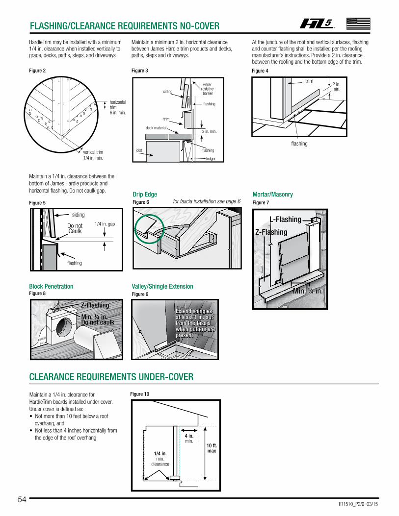
FLASHING/CLEARANCE REQUIREMENTS NO-COVER
vertical trim1/4 in. min.
horizontaltrim6 in. min.
HardieTrim may be installed with a minimum 1/4 in. clearance when installed vertically to grade, decks, paths, steps, and driveways
Figure 2
At the juncture of the roof and vertical surfaces, flashing and counter flashing shall be installed per the roofing manufacturer’s instructions. Provide a 2 in. clearance between the roofing and the bottom edge of the trim.
Figure 4
Maintain a minimum 2 in. horizontal clearance between James Hardie trim products and decks, paths, steps and driveways.
Figure 3
joist
2 in. min.
water resistive barriersiding
flashing
deck material
ledger
trim
flashing
siding
1/4 in. gap
flashing
Do notCaulk
Figure 5
Maintain a 1/4 in. clearance between the bottom of James Hardie products and horizontal flashing. Do not caulk gap.
2 in.min.
flashing
trim
Block PenetrationFigure 8
Z-Flashing
Min. ¼ in.Do not caulk
Drip EdgeFigure 6 for fascia installation see page 6
Valley/Shingle ExtensionFigure 9
Extend shingles at least 1 in. out from the fascia when gutters are present
Extend shingles at least 1 in. out from the fascia when gutters are present
Mortar/MasonryFigure 7
Figure 10
CLEARANCE REQUIREMENTS UNDER-COVER
1/4 in. min.
clearance
4 in. min.
10 ft. max
Z-Flashing
L-Flashing
Min. ¼ in.Min. ¼ in.
Maintain a 1/4 in. clearance for HardieTrim boards installed under cover. Under cover is defined as:• Not more than 10 feet below a roof
overhang, and• Not less than 4 inches horizontally from
the edge of the roof overhang
55
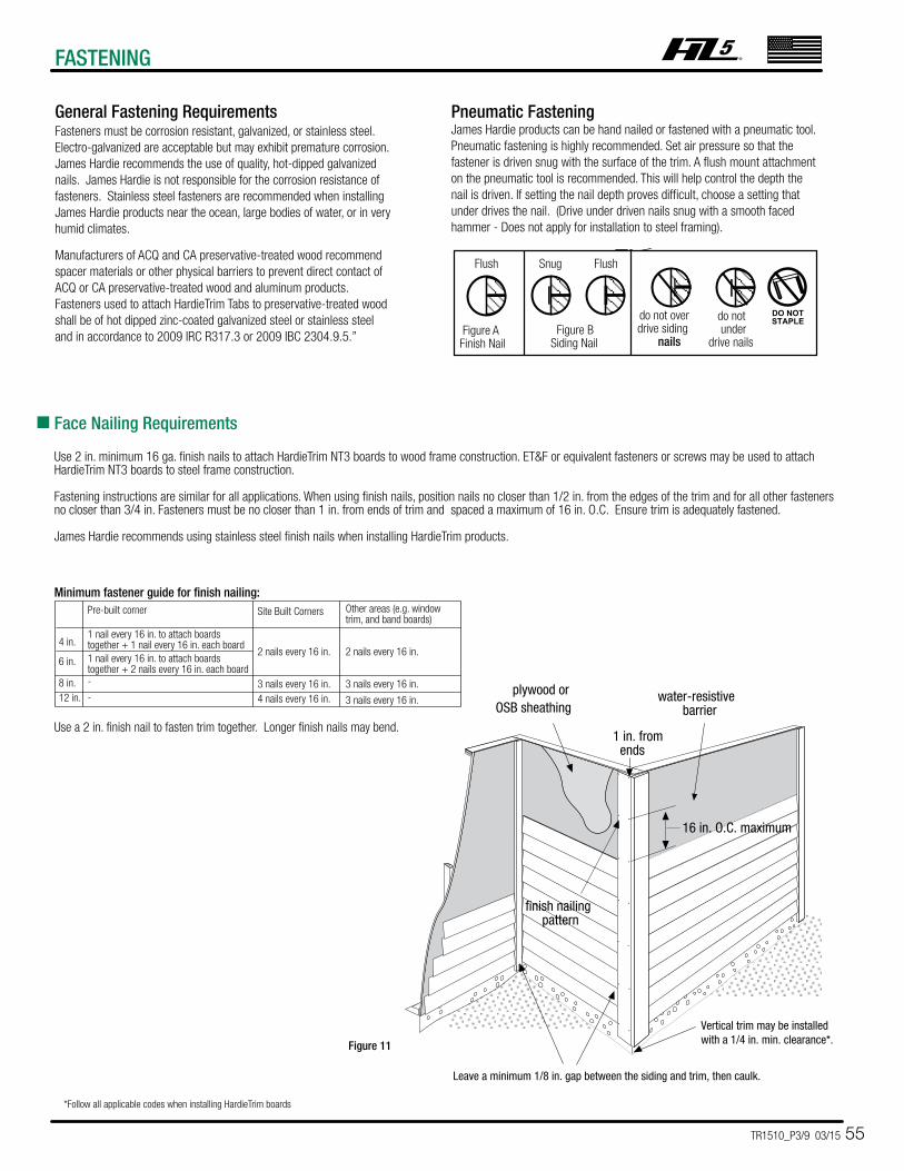
16 in. O.C. maximum
Leave a minimum 1/8 in. gap between the siding and trim, then caulk.
finish nailingpattern
plywood orOSB sheathing
water-resistivebarrier
1 in. fromends
Figure 11
Use 2 in. minimum 16 ga. finish nails to attach HardieTrim NT3 boards to wood frame construction. ET&F or equivalent fasteners or screws may be used to attach HardieTrim NT3 boards to steel frame construction.
Fastening instructions are similar for all applications. When using finish nails, position nails no closer than 1/2 in. from the edges of the trim and for all other fasteners no closer than 3/4 in. Fasteners must be no closer than 1 in. from ends of trim and spaced a maximum of 16 in. O.C. Ensure trim is adequately fastened.
James Hardie recommends using stainless steel finish nails when installing HardieTrim products.
Use a 2 in. finish nail to fasten trim together. Longer finish nails may bend.
Minimum fastener guide for finish nailing:
4 in.
6 in.
8 in.12 in.
Site Built Corners
2 nails every 16 in.
3 nails every 16 in.4 nails every 16 in.
Other areas (e.g. window trim, and band boards)
2 nails every 16 in.
3 nails every 16 in.
3 nails every 16 in.
Pre-built corner
1 nail every 16 in. to attach boards together + 1 nail every 16 in. each board1 nail every 16 in. to attach boards together + 2 nails every 16 in. each board-
-
Face Nailing Requirements
Vertical trim may be installedwith a 1/4 in. min. clearance*.
TR1510_P3/9 03/15
*Follow all applicable codes when installing HardieTrim boards
FASTENING
Fasteners must be corrosion resistant, galvanized, or stainless steel. Electro-galvanized are acceptable but may exhibit premature corrosion. James Hardie recommends the use of quality, hot-dipped galvanized nails. James Hardie is not responsible for the corrosion resistance of fasteners. Stainless steel fasteners are recommended when installing James Hardie products near the ocean, large bodies of water, or in veryhumid climates.
General Fastening Requirements Pneumatic FasteningJames Hardie products can be hand nailed or fastened with a pneumatic tool. Pneumatic fastening is highly recommended. Set air pressure so that the fastener is driven snug with the surface of the trim. A flush mount attachment on the pneumatic tool is recommended. This will help control the depth the nail is driven. If setting the nail depth proves difficult, choose a setting that under drives the nail. (Drive under driven nails snug with a smooth faced hammer - Does not apply for installation to steel framing).
Manufacturers of ACQ and CA preservative-treated wood recommend spacer materials or other physical barriers to prevent direct contact of ACQ or CA preservative-treated wood and aluminum products. Fasteners used to attach HardieTrim Tabs to preservative-treated wood shall be of hot dipped zinc-coated galvanized steel or stainless steel and in accordance to 2009 IRC R317.3 or 2009 IBC 2304.9.5.” Figure B
Siding Nail
do not under
drive nails Figure AFinish Nail
Flush Snug Flush
do not overdrive siding
nails
56 TR1510_P4/9 03/15
Frieze BoardsHardieTrim boards can be used as frieze board. (figure 16)
Figure 16
Butt-to Siding
HardieTrimfrieze board
Trim Over Siding
Shim behind trim
HardieTrim frieze board
blocking/supportif required
sheathing
water resistive barrier
lap siding
1/4 in. gap
flashing
HardieTrim NT3 board
caulk if required
HardiePlank lap siding
Figure 15
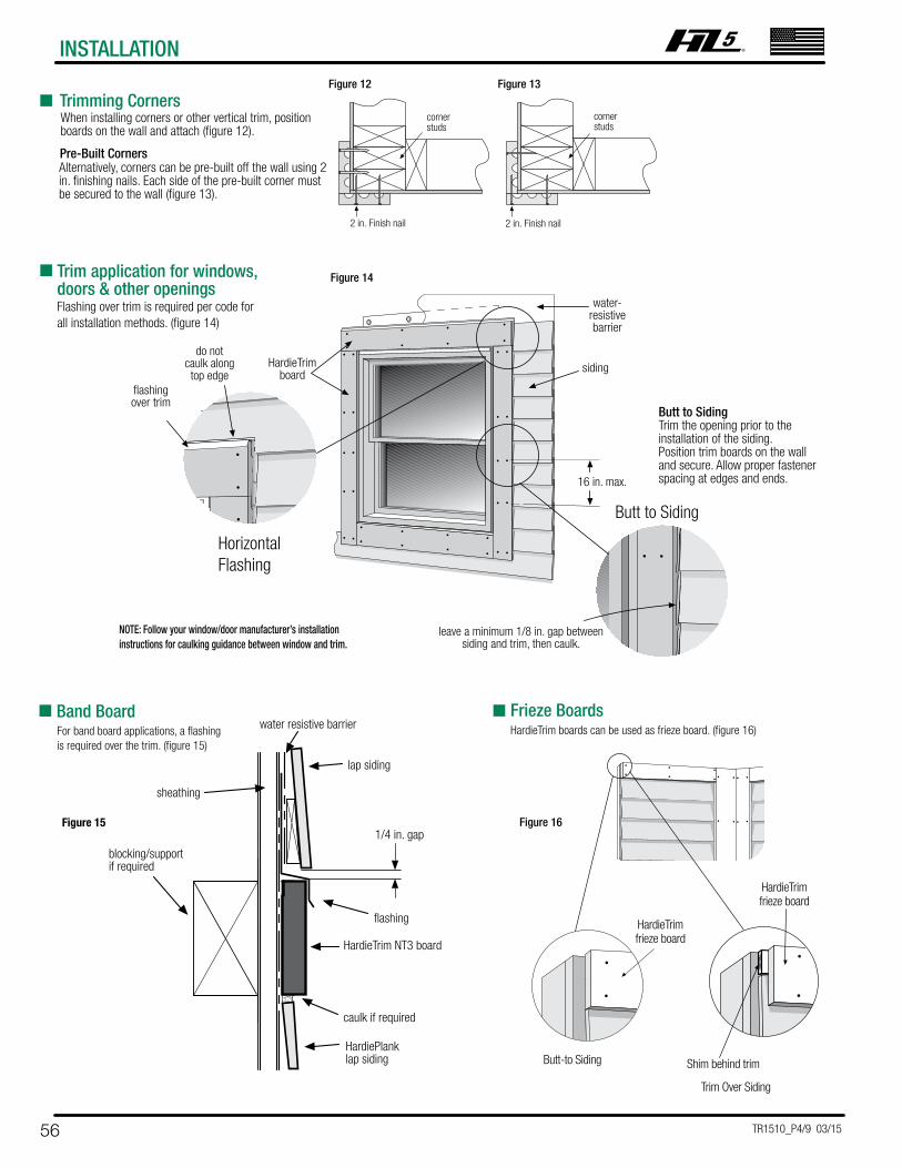
For band board applications, a flashingis required over the trim. (figure 15)
Band Board
Butt to Siding
Horizontal Flashing
leave a minimum 1/8 in. gap between siding and trim, then caulk.
Figure 14
flashing over trim
do notcaulk alongtop edge
HardieTrimboard
water-resistivebarrier
siding
16 in. max.
NOTE: Follow your window/door manufacturer’s installation instructions for caulking guidance between window and trim.
Trim application for windows,doors & other openingsFlashing over trim is required per code forall installation methods. (figure 14)
Butt to SidingTrim the opening prior to theinstallation of the siding.Position trim boards on the walland secure. Allow proper fastenerspacing at edges and ends.
cornerstuds
Figure 12 Figure 13
Trimming Corners
INSTALLATION
When installing corners or other vertical trim, positionboards on the wall and attach (figure 12).
Pre-Built CornersAlternatively, corners can be pre-built off the wall using 2 in. finishing nails. Each side of the pre-built corner must be secured to the wall (figure 13).
2 in. Finish nail2 in. Finish nail
cornerstuds
57TR1510_P5/9 03/15
INSTALLATION (cont.)
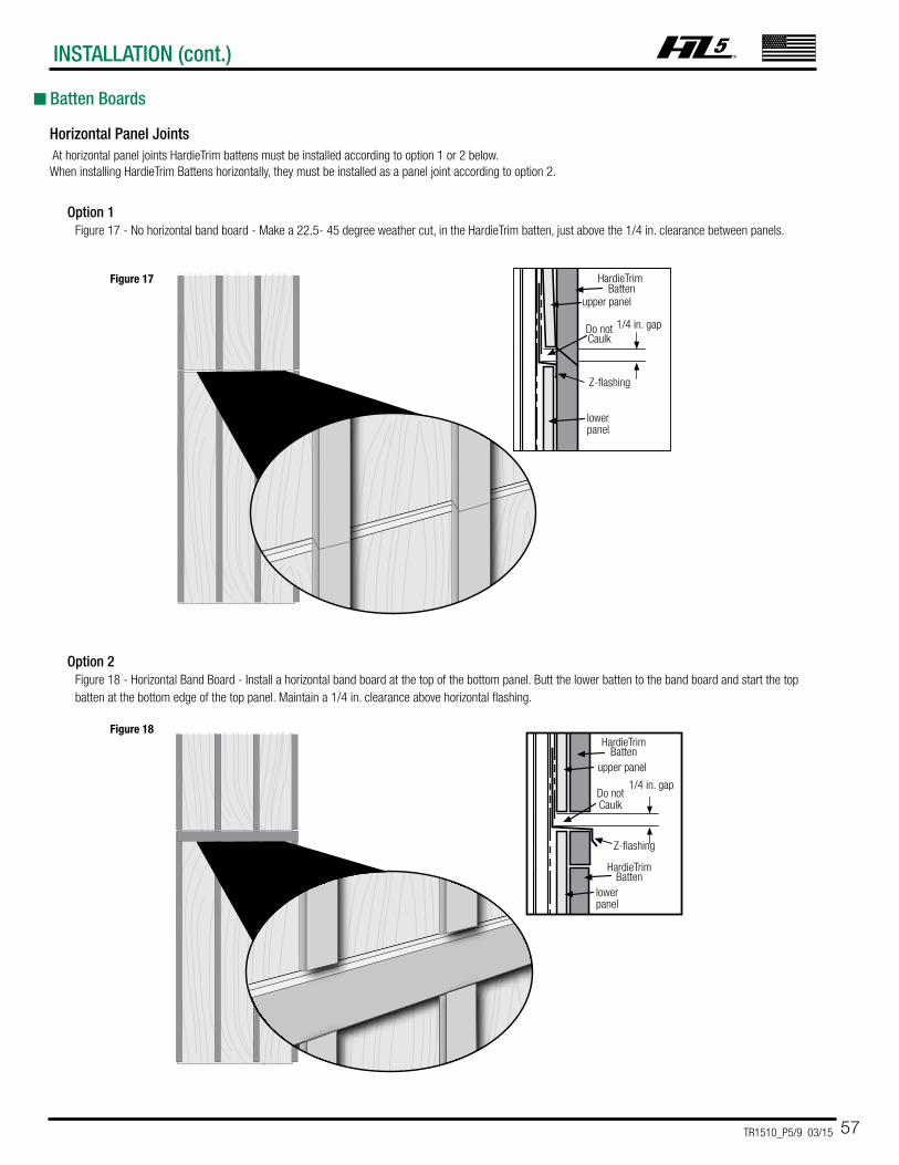
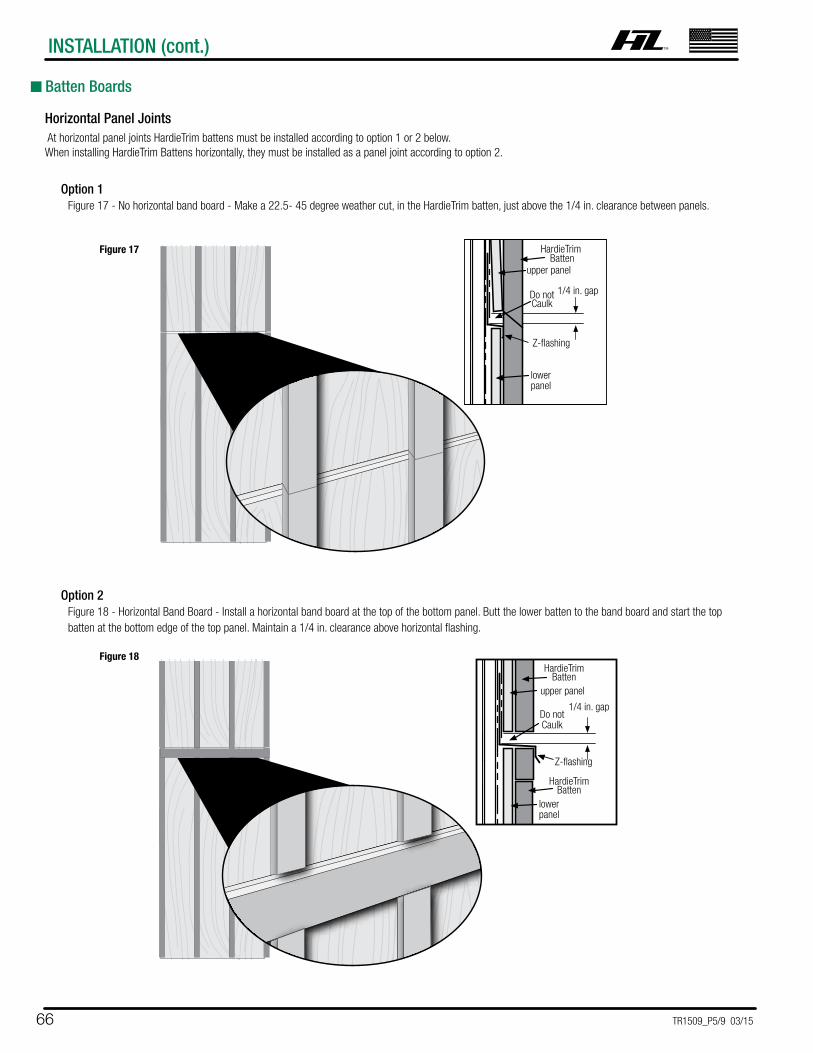
Horizontal Panel Joints At horizontal panel joints HardieTrim battens must be installed according to option 1 or 2 below.When installing HardieTrim Battens horizontally, they must be installed as a panel joint according to option 2.
Option 1 Figure 17 - No horizontal band board - Make a 22.5- 45 degree weather cut, in the HardieTrim batten, just above the 1/4 in. clearance between panels.
Option 2 Figure 18 - Horizontal Band Board - Install a horizontal band board at the top of the bottom panel. Butt the lower batten to the band board and start the top batten at the bottom edge of the top panel. Maintain a 1/4 in. clearance above horizontal flashing.
1/4 in. gap
lowerpanel
Z-flashing
upper panel
Do notCaulk
HardieTrim Batten
1/4 in. gap
Z-flashing
upper panel
Do notCaulk
HardieTrimBatten
HardieTrimBatten
lowerpanel
Batten Boards
Figure 17
Figure 18
58 TR1510_P6/9 05/15
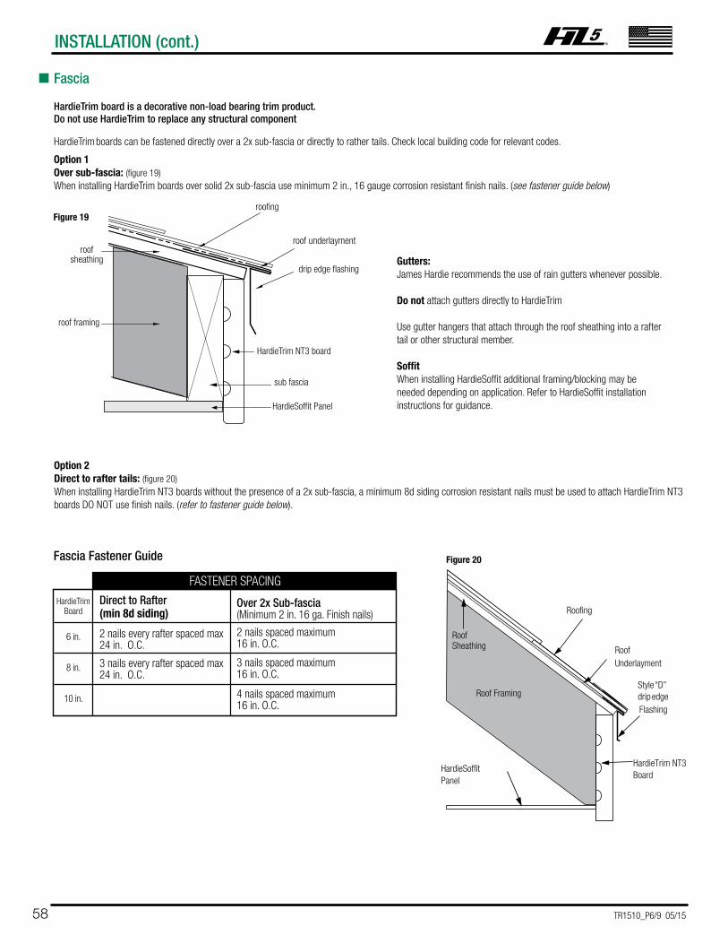
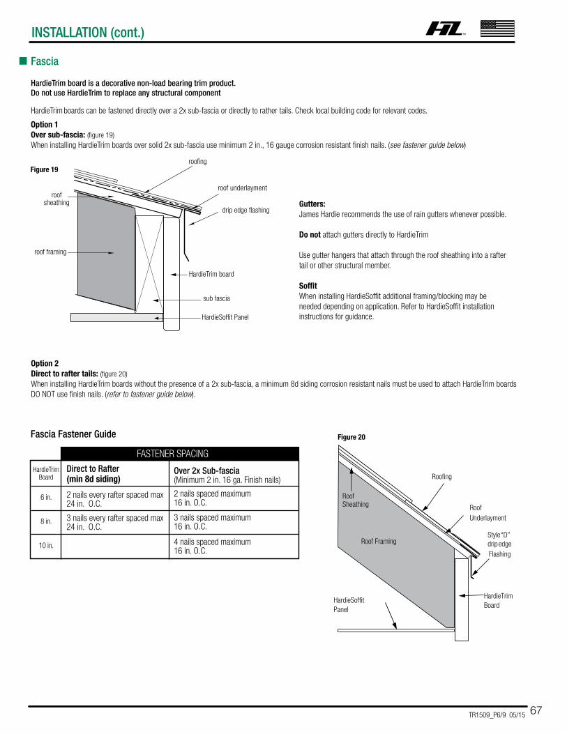
HardieTrim board is a decorative non-load bearing trim product.
Fascia
Figure 19
roof sheathing
roof framing
roofing
roof underlayment
drip edge flashing
HardieTrim NT3 board
sub fascia
HardieSoffit Panel
Do not use HardieTrim to replace any structural component
HardieTrim boards can be fastened directly over a 2x sub-fascia or directly to rather tails. Check local building code for relevant codes.
Option 1Over sub-fascia: (figure 19)When installing HardieTrim boards over solid 2x sub-fascia use minimum 2 in., 16 gauge corrosion resistant finish nails. (see fastener guide below)
Option 2Direct to rafter tails: (figure 20) When installing HardieTrim NT3 boards without the presence of a 2x sub-fascia, a minimum 8d siding corrosion resistant nails must be used to attach HardieTrim NT3 boards DO NOT use finish nails. (refer to fastener guide below).
HardieTrim Board
6 in.
8 in.
10 in.
Over 2x Sub-fascia(Minimum 2 in. 16 ga. Finish nails)
FASTENER SPACING
Direct to Rafter (min 8d siding)
2 nails every rafter spaced max 24 in. O.C.
3 nails every rafter spaced max 24 in. O.C.
2 nails spaced maximum 16 in. O.C.
3 nails spaced maximum 16 in. O.C.
4 nails spaced maximum 16 in. O.C.
Figure 20
Roofing
RoofUnderlayment
Style“D”dripedgeFlashing
HardieTrim NT3Board
HardieSoffit Panel
Roof Framing
RoofSheathing
INSTALLATION (cont.)
Gutters:James Hardie recommends the use of rain gutters whenever possible.
Do not attach gutters directly to HardieTrim
Use gutter hangers that attach through the roof sheathing into a rafter tail or other structural member.
SoffitWhen installing HardieSoffit additional framing/blocking may be needed depending on application. Refer to HardieSoffit installation instructions for guidance.
Fascia Fastener Guide
59TR1510_P7/9 03/15
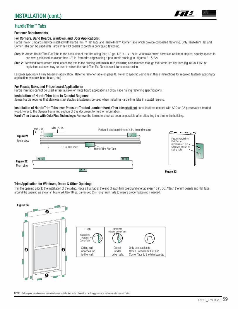
Fastener Requirements
Trim Application for Windows, Doors & Other Openings
For Corners, Band Boards, Windows, and Door Applications:HardieTrim NT3 boards may be installed with HardieTrim™ Flat Tabs and HardieTrim™ Corner Tabs which provide concealed fastening. Only HardieTrim Flat and Corner Tabs can be used with HardieTrim NT3 boards to create a concealed fastening.
Step 1: Attach HardieTrim Flat Tabs to the back side of the trim using four, 18 ga. 1/2 in. L x 1/4 in. W narrow crown corrosion resistant staples, equally spaced in one row, positioned no closer than 1/2 in. from trim edges using a pneumatic staple gun. (figures 21 & 22)
Step 2: For wood frame construction, attach the trim to the building with minimum 2, 6d siding nails fastened through the HardieTrim Flat Tabs (figure23). ET&F or equivalent fasteners may be used to attach the HardieTrim Flat Tabs to steel frame construction.
Fastener spacing will vary based on application. Refer to fastener table on page 8. Refer to specific sections in these instructions for required fastener spacing by application (window, band board, etc.)
For Fascia, Rake, and Frieze board Applications:HardieTrim tabs cannot be used in fascia, rake, or frieze board applications. Follow Face nailing fastening specifications. Installation of HardieTrim tabs in Coastal Regions:James Hardie requires that stainless steel staples & fasteners be used when installing HardieTrim Tabs in coastal regions.
Installation of HardieTrim Tabs over Pressure Treated Lumber: HardieTrim tabs shall not come in direct contact with ACQ or CA preservative-treated wood. Refer to the General Fastening section of this document for further information.HardieTrim boards with ColorPlus Technology: Remove the laminate sheet as soon as possible after attaching the trim to the building.
Figure 23
Fasten HardieTrimFlat Tab to minimum 7/16 in. OSB with min 2, 6d siding nails
Min 2 in. Min 1/2 in.
Figure 24
NOTE: Follow your window/door manufacturers installation instructions for caulking guidance between window and trim.
Do not under
drive nails.
HardieTrim
Flat and Corner TabsHardieTrim
Flat andCorner Tabs
Only use staples tofasten HardieTrim Flat andCorner Tabs to the trim boards.
Siding nailattaches tabto the wall.
Flush
HardieTrim™ Tabs
Trim the opening prior to the installation of the siding. Place a Flat Tab at the end of each trim board and one tab every 16 in. OC. Attach the trim boards and Flat Tabs around the opening as shown in figure 24. Use 16 ga. galvanized 2 in. long finish nails to ensure proper fastening if needed.
Figure 21
Figure 22
Fasten 4 staples minimum ¼ in. from trim edge
HardieTrim Flat Tabs16 in. O.C. max
Back view
Front view
INSTALLATION (cont.)
1
2
3
2
60 TR1510_P8/9 03/15
Band Board
Trimming Corners
Trim TabFastener Table
Figure 25 Figure 25
Use 4 staples per pieceof trim to fasten theL-shaped tab to thepre-built corner. Usethe nail line on thetabs as a guide.
Corner studsFasten 2 in. x 4 in.timber blocksto a work bench
HardieTrim Corner Tabs
Fasten 2 in. x 8 in. studto the timber blocks
HardieTrimNT3 Boards
Siding nail
HardieTrim Corner Tab
HardieTrim Corner Tab
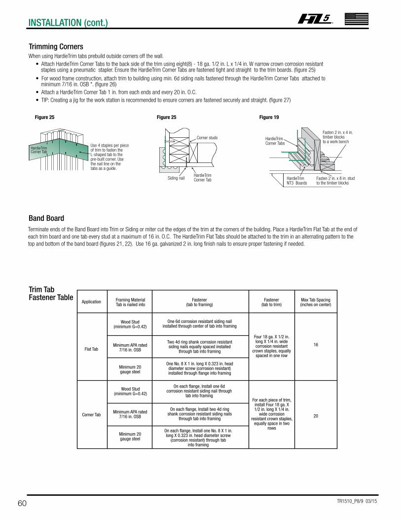
Figure 19
When using HardieTrim tabs prebuild outside corners off the wall. • Attach HardieTrim Corner Tabs to the back side of the trim using eight(8) - 18 ga. 1/2 in. L x 1/4 in. W narrow crown corrosion resistant
staples using a pneumatic stapler. Ensure the HardieTrim Corner Tabs are fastened tight and straight to the trim boards. (figure 25)
• For wood frame construction, attach trim to building using min. 6d siding nails fastened through the HardieTrim Corner Tabs attached tominimum 7/16 in. OSB *. (figure 26)
• Attach a HardieTrim Corner Tab 1 in. from each ends and every 20 in. O.C. • TIP: Creating a jig for the work station is recommended to ensure corners are fastened securely and straight. (figure 27)
Terminate ends of the Band Board into Trim or Siding or miter cut the edges of the trim at the corners of the building. Place a HardieTrim Flat Tab at the end of each trim board and one tab every stud at a maximum of 16 in. O.C. The HardieTrim Flat Tabs should be attached to the trim in an alternating pattern to the top and bottom of the band board (figures 21, 22). Use 16 ga. galvanized 2 in. long finish nails to ensure proper fastening if needed.
Application Framing MaterialTab is nailed into
Flat Tab
Wood Stud(minimum G=0.42)
Minimum APA rated7/16 in. OSB
Corner TabMinimum APA rated
7/16 in. OSB
Minimum 20gauge steel
Minimum 20gauge steel
Wood Stud(minimum G=0.42)
Fastener(tab to trim)
Max Tab Spacing(inches on center)
Four 18 ga. X 1/2 in. long X 1/4 in. wide corrosion resistant
crown staples, equally spaced in one row
16
For each piece of trim, install Four 18 ga. X 1/2 in. long X 1/4 in.
wide corrosion resistant crown staples,
equally space in two rows
20
Fastener(tab to framing)
One 6d corrosion resistant siding nailinstalled through center of tab into framing
Two 4d ring shank corrosion resistantsiding nails equally spaced installed
through tab into framing
One No. 8 X 1 in. long X 0.323 in. headdiameter screw (corrosion resistant)installed through flange into framing
On each flange, Install one 6dcorrosion resistant siding nail through
tab into framing
On each flange, Install two 4d ringshank corrosion resistant siding nails
through tab into framing
On each flange, Install one No. 8 X 1 in.long X 0.323 in. head diameter screw
(corrosion resistant) through tabinto framing
INSTALLATION (cont.)
61
CaulkingFor best results use an Elastomeric Joint Sealant complying with ASTM C920 Grade NS, Class 25 or higher or a Latex Joint Sealant complying with ASTM C834. Caulking/Sealant must be applied in accordance with the caulking/sealant manufacturer’s written instructions. For best results use an Elastomeric Joint Sealant complying with ASTM C920 Grade NS, Class 25 or higher or a Latex Joint Sealant complying with ASTM C834. Caulking/Sealant must be applied in accordance with the caulking/sealant manufacturer’s written instructions.
ColorPlus Technology Caulking, Touch-up & Laminate
When repainting ColorPlus products, James Hardie recommends the following regarding surface preparation and topcoat application:• Ensure the surface is clean, dry, and free of any dust, dirt, or mildew• Repriming is normally not necessary• 100% acrylic topcoats are recommended• DO NOT use stain, oil/alkyd base paint, or powder coating on James Hardie Products.• Apply finish coat in accordance with paint manufacturers written instructions regarding coverage, application methods, and application temperature• DO NOT caulk nail heads when using ColorPlus products, refer to the ColorPlus touch-up section
Cut Edge TreatmentCaulk, paint or prime all field cut edges. James Hardie touch-up kits are required to touch-up ColorPlus products.
• Care should be taken when handling and cutting James Hardie ColorPlus products. During installation use a wet soft cloth or soft brush to gently wipe off any residue or construction dust left on the product, then rinse with a garden hose.• Touch up nicks, scrapes and nail heads using the ColorPlus Technology touch-up applicator. Touch-up should be used sparingly. If large areas require touch-up, replace the damaged area with new HardieTrim board with ColorPlus Technology.• Laminate sheet must be removed immediately after installation. Nail head touch-up can be done before or after removal of the laminate sheet when using finish nails. The preferred method is to touch-up while the laminate sheet is in place. Remove the laminate sheet before paint dries.• Terminate non-factory cut edges into trim where possible, and caulk. Color matched caulks are available from your ColorPlus product dealer.• Treat all other non-factory cut edges using the ColorPlus Technology edge coaters, available from your ColorPlus product dealer.
Note: James Hardie does not warrant the usage of third party touch-up or paints used as touch-up on James Hardie ColorPlus products.
Problems with appearance or performance arising from use of third party touch-up paints or paints used as touch-up that are not James Hardie touch-up, will not be covered under the James Hardie ColorPlus Limited Finish Warranty.
TR1510_P9/9 03/15
Additional Installation Information, Warranties, and Warnings are available at
www.jameshardie.com
© 2015 James Hardie Building Products. All rights reserved.TM, SM, and ® denote trademarks or registered trademarks of James Hardie Technology Limited. is a registered trademark of James Hardie Technology Limited.
RECOGNITION: HardieTrim boards may be installed as an equal alternative to conventional trim permitted for use in; 2006, 2009, & 2012 International Building Code, Section 1402.1, and the 2006, 2009, & 2012 International Residence Code for One - and Two - Family - Dwellings, Section R703.1.
Painting James Hardie Siding and Trim Products with ColorPlus Technology
FINISHING
PaintingDO NOT use stain, oil/alkyd base paint, or powder coating on James Hardie Products. James Hardie products must be painted within 180 days for primed product and 90 days for unprimed. 100% acrylic topcoats are recommended. Do not paint when wet. For application rates refer to paint manufacturers specifications. Back-rolling is recommended if the siding is sprayed.
62 TR1509_P1/9 03/15
James Hardie products contain respirable crystalline silica, which is known to the State of California to cause cancer and is considered by IARC and NIOSH to be a cause of cancer from some occupational sources. Breathing excessive amounts of respirable silica dust can also cause a disabling and potentially fatal lung disease called silicosis, and has been linked with other diseases. Some studies suggest smoking may increase these risks. During installation or handling: (1) work in outdoor areas with ample ventilation; (2) use fiber cement shears for cutting or, where not feasible, use a HardieBlade saw blade and dust-reducing circular saw attached to a HEPA vacuum; (3) warn others in the immediate area; (4) wear a properly-fitted, NIOSH-approved dust mask or respirator (e.g. N-95) in accordance with applicable government regulations and manufacturer instructions to further limit respirable silica exposures. During clean-up, use HEPA vacuums or wet cleanup methods - never dry sweep. For further information, refer to our installation instructions and Material Safety Data Sheet available at www.jameshardie.com or by calling 1-800-9HARDIE (1-800-942-7343). FAILURE TO ADHERE TO OUR WARNINGS, MSDS, AND INSTALLATION INSTRUCTIONS MAY LEAD TO SERIOUS PERSONAL INJURY OR DEATH. SD050905
TABLE OF CONTENTS:
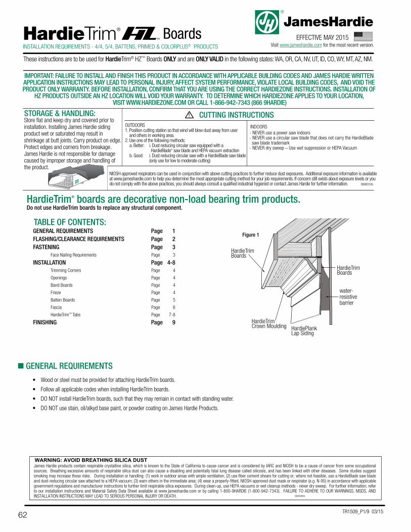
HardieTrim® boards are decorative non-load bearing trim products.
INSTALLATION REQUIREMENTS - 4/4, 5/4, BATTENS, PRIMED & COLORPLUS® PRODUCTS Visit www.jameshardie.com for the most recent version.
Boards
OUTDOORS1. Position cutting station so that wind will blow dust away from user and others in working area.2. Use one of the following methods: a. Better: i. Dust reducing circular saw equipped with a HardieBlade® saw blade and HEPA vacuum extraction b. Good: i. Dust reducing circular saw with a HardieBlade saw blade (only use for low to moderate cutting)
INDOORS - NEVER use a power saw indoors - NEVER use a circular saw blade that does not carry the HardieBlade saw blade trademark- NEVER dry sweep – Use wet suppression or HEPA Vacuum
NIOSH-approved respirators can be used in conjunction with above cutting practices to further reduce dust exposures. Additional exposure information is available at www.jameshardie.com to help you determine the most appropriate cutting method for your job requirements. If concern still exists about exposure levels or you do not comply with the above practices, you should always consult a qualified industrial hygienist or contact James Hardie for further information. SD083105
CUTTING INSTRUCTIONSSTORAGE & HANDLING:
IMPORTANT: FAILURE TO INSTALL AND FINISH THIS PRODUCT IN ACCORDANCE WITH APPLICABLE BUILDING CODES AND JAMES HARDIE WRITTEN APPLICATION INSTRUCTIONS MAY LEAD TO PERSONAL INJURY, AFFECT SYSTEM PERFORMANCE, VIOLATE LOCAL BUILDING CODES, AND VOID THE PRODUCT ONLY WARRANTY. BEFORE INSTALLATION, CONFIRM THAT YOU ARE USING THE CORRECT HARDIEZONE INSTRUCTIONS. INSTALLATION OF
HZ PRODUCTS OUTSIDE AN HZ LOCATION WILL VOID YOUR WARRANTY. TO DETERMINE WHICH HARDIEZONE APPLIES TO YOUR LOCATION, VISIT WWW.HARDIEZONE.COM OR CALL 1-866-942-7343 (866 9HARDIE)
These instructions are to be used for HardieTrim® HZ™ Boards ONLY and are ONLY VALID in the following states: WA, OR, CA, NV, UT, ID, CO, WY, MT, AZ, NM.
Store flat and keep dry and covered prior to installation. Installing James Hardie siding product wet or saturated may result in shrinkage at butt joints. Carry product on edge. Protect edges and corners from breakage. James Hardie is not responsible for damage caused by improper storage and handling ofthe product.
GENERAL REQUIREMENTS Page 1FLASHING/CLEARANCE REQUIREMENTS Page 2FASTENING Page 3 Face Nailing Requirements Page 3
INSTALLATION Page 4-8 Trimming Corners Page 4
Openings Page 4
Band Boards Page 4
Frieze Page 4
Batten Boards Page 5
Fascia Page 6
HardieTrim™ Tabs Page 7-8
FINISHING Page 9
• Wood or steel must be provided for attaching HardieTrim boards.
• Follow all applicable codes when installing HardieTrim boards.
• DO NOT install HardieTrim boards, such that they may remain in contact with standing water.
• DO NOT use stain, oil/alkyd base paint, or powder coating on James Hardie Products.
Do not use HardieTrim boards to replace any structural component.
GENERAL REQUIREMENTS
HardieTrimBoards
HardieTrimBoards
HardiePlankLap Siding
HardieTrimCrown Moulding
water- resistivebarrier
Figure 1
EFFECTIVE MAY 2015
63TR1509_P2/9 03/15
FLASHING/CLEARANCE REQUIREMENTS NO-COVER
vertical trim1/4 in. min.
horizontaltrim6 in. min.
HardieTrim may be installed with a minimum 1/4 in. clearance when installed vertically to grade, decks, paths, steps, and driveways
Figure 2
At the juncture of the roof and vertical surfaces, flashing and counter flashing shall be installed per the roofing manufacturer’s instructions. Provide a 1 in. clearance between the roofing and the bottom edge of the trim.
Figure 4
Maintain a minimum 1 in. horizontal clearance between James Hardie trim products and decks, paths, steps and driveways.
Figure 3
joist
1 in. min.
water resistive barriersiding
flashing
deck material
ledger
trim
flashing
siding
1/4 in. gap
flashing
Do notCaulk
Figure 5
Maintain a 1/4 in. clearance between the bottom of James Hardie products and horizontal flashing. Do not caulk gap.
1 in.min.
flashing
trim
Block PenetrationFigure 8
Z-Flashing
Min. ¼ in.Do not caulk
Drip EdgeFigure 6 for fascia installation see page 6
Valley/Shingle ExtensionFigure 9
Extend shingles at least 1 in. out from the fascia when gutters are present
Extend shingles at least 1 in. out from the fascia when gutters are present
Mortar/MasonryFigure 7
CLEARANCE REQUIREMENTS UNDER-COVER
Z-Flashing
L-Flashing
Min. ¼ in.Min. ¼ in.
Figure 10
1/4 in. min.
clearance
4 in. min.
10 ft. max
Maintain a 1/4 in. clearance for HardieTrim boards installed under cover. Under cover is defined as:• Not more than 10 feet below a roof
overhang, and• Not less than 4 inches horizontally from
the edge of the roof overhang

64
16 in. O.C. maximum
Leave a minimum 1/8 in. gap between the siding and trim, then caulk.
finish nailingpattern
plywood orOSB sheathing
water-resistivebarrier
1 in. fromends
Figure 11
Use 2 in. minimum 16 ga. finish nails to attach HardieTrim boards to wood frame construction. ET&F or equivalent fasteners or screws may be used to attach HardieTrim boards to steel frame construction.
Fastening instructions are similar for all applications. When using finish nails, position nails no closer than 1/2 in. from the edges of the trim and for all other fasteners no closer than 3/4 in. Fasteners must be no closer than 1 in. from ends of trim and spaced a maximum of 16 in. O.C. Ensure trim is adequately fastened.
James Hardie recommends using stainless steel finish nails when installing HardieTrim products.
Use a 2 in. finish nail to fasten trim together. Longer finish nails may bend.
Minimum fastener guide for finish nailing:
4 in.
6 in.
8 in.12 in.
Site Built Corners
2 nails every 16 in.
3 nails every 16 in.4 nails every 16 in.
Other areas (e.g. window trim, and band boards)
2 nails every 16 in.
3 nails every 16 in.
3 nails every 16 in.
Pre-built corner
1 nail every 16 in. to attach boards together + 1 nail every 16 in. each board1 nail every 16 in. to attach boards together + 2 nails every 16 in. each board-
-
Face Nailing Requirements
Vertical trim may be installedwith a 1/4 in. min. clearance*.
TR1509_P3/9 03/15
*Follow all applicable codes when installing HardieTrim boards
FASTENING
Fasteners must be corrosion resistant, galvanized, or stainless steel. Electro-galvanized are acceptable but may exhibit premature corrosion. James Hardie recommends the use of quality, hot-dipped galvanized nails. James Hardie is not responsible for the corrosion resistance of fasteners. Stainless steel fasteners are recommended when installing James Hardie products near the ocean, large bodies of water, or in veryhumid climates.
General Fastening Requirements Pneumatic FasteningJames Hardie products can be hand nailed or fastened with a pneumatic tool. Pneumatic fastening is highly recommended. Set air pressure so that the fastener is driven snug with the surface of the trim. A flush mount attachment on the pneumatic tool is recommended. This will help control the depth the nail is driven. If setting the nail depth proves difficult, choose a setting that under drives the nail. (Drive under driven nails snug with a smooth faced hammer - Does not apply for installation to steel framing).
Manufacturers of ACQ and CA preservative-treated wood recommend spacer materials or other physical barriers to prevent direct contact of ACQ or CA preservative-treated wood and aluminum products. Fasteners used to attach HardieTrim Tabs to preservative-treated wood shall be of hot dipped zinc-coated galvanized steel or stainless steel and in accordance to 2009 IRC R317.3 or 2009 IBC 2304.9.5.” Figure B
Siding Nail
do not under
drive nails Figure AFinish Nail
Flush Snug Flush
do not overdrive siding
nails
65TR1509_P4/9 03/15
Frieze BoardsHardieTrim boards can be used as frieze board. (figure 16)
Figure 16
Butt-to Siding
HardieTrimfrieze board
Trim Over Siding
Shim behind trim
HardieTrim frieze board
blocking/supportif required
sheathing
water resistive barrier
lap siding
1/4 in. gap
flashing
HardieTrim board
caulk if required
HardiePlank lap siding
Figure 15
For band board applications, a flashingis required over the trim. (figure 15)
Band Board
cornerstuds
Figure 12 Figure 13
Trimming Corners
INSTALLATION
2 in. Finish nail2 in. Finish nail
cornerstuds
Butt to Siding
Horizontal Flashing
leave a minimum 1/8 in. gap between siding and trim, then caulk.
Figure 14
flashing over trim
do notcaulk alongtop edge
HardieTrimboard
water-resistivebarrier
siding
16 in. max.
NOTE: Follow your window/door manufacturer’s installation instructions for caulking guidance between window and trim.
Trim application for windows,doors & other openingsFlashing over trim is required per code forall installation methods. (figure 14)
Butt to SidingTrim the opening prior to theinstallation of the siding.Position trim boards on the walland secure. Allow proper fastenerspacing at edges and ends.
When installing corners or other vertical trim, positionboards on the wall and attach (figure 12).
Pre-Built CornersAlternatively, corners can be pre-built off the wall using 2 in. finishing nails. Each side of the pre-built corner must be secured to the wall (figure 13).
66 TR1509_P5/9 03/15
INSTALLATION (cont.)
Horizontal Panel Joints At horizontal panel joints HardieTrim battens must be installed according to option 1 or 2 below.When installing HardieTrim Battens horizontally, they must be installed as a panel joint according to option 2.
Option 1 Figure 17 - No horizontal band board - Make a 22.5- 45 degree weather cut, in the HardieTrim batten, just above the 1/4 in. clearance between panels.
Option 2 Figure 18 - Horizontal Band Board - Install a horizontal band board at the top of the bottom panel. Butt the lower batten to the band board and start the top batten at the bottom edge of the top panel. Maintain a 1/4 in. clearance above horizontal flashing.
1/4 in. gap
lowerpanel
Z-flashing
upper panel
Do notCaulk
HardieTrim Batten
1/4 in. gap
Z-flashing
upper panel
Do notCaulk
HardieTrimBatten
HardieTrimBatten
lowerpanel
Batten Boards
Figure 17
Figure 18
67TR1509_P6/9 05/15
HardieTrim board is a decorative non-load bearing trim product.
Fascia
Figure 19
roof sheathing
roof framing
roofing
roof underlayment
drip edge flashing
HardieTrim board
sub fascia
HardieSoffit Panel
Do not use HardieTrim to replace any structural component
HardieTrim boards can be fastened directly over a 2x sub-fascia or directly to rather tails. Check local building code for relevant codes.
Option 1Over sub-fascia: (figure 19)When installing HardieTrim boards over solid 2x sub-fascia use minimum 2 in., 16 gauge corrosion resistant finish nails. (see fastener guide below)
Gutters:James Hardie recommends the use of rain gutters whenever possible.
Do not attach gutters directly to HardieTrim
Use gutter hangers that attach through the roof sheathing into a rafter tail or other structural member.
SoffitWhen installing HardieSoffit additional framing/blocking may be needed depending on application. Refer to HardieSoffit installation instructions for guidance.
Option 2Direct to rafter tails: (figure 20) When installing HardieTrim boards without the presence of a 2x sub-fascia, a minimum 8d siding corrosion resistant nails must be used to attach HardieTrim boards DO NOT use finish nails. (refer to fastener guide below).
HardieTrim Board
6 in.
8 in.
10 in.
Over 2x Sub-fascia(Minimum 2 in. 16 ga. Finish nails)
FASTENER SPACING
Direct to Rafter (min 8d siding)
2 nails every rafter spaced max 24 in. O.C.
3 nails every rafter spaced max 24 in. O.C.
2 nails spaced maximum 16 in. O.C.
3 nails spaced maximum 16 in. O.C.
4 nails spaced maximum 16 in. O.C.
Figure 20
Roofing
RoofUnderlayment
Style“D”dripedgeFlashing
HardieTrimBoard
HardieSoffit Panel
Roof Framing
RoofSheathing
INSTALLATION (cont.)
Fascia Fastener Guide
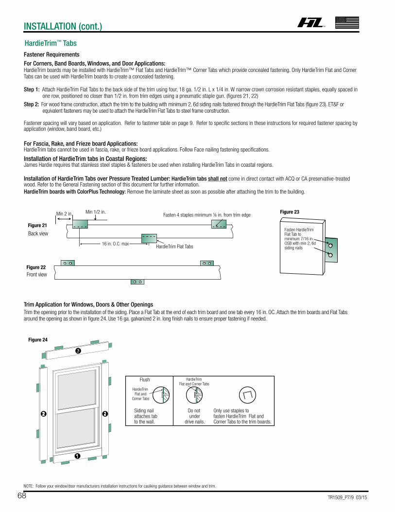
68 TR1509_P7/9 03/15
Fastener Requirements
Trim Application for Windows, Doors & Other Openings
For Corners, Band Boards, Windows, and Door Applications:HardieTrim boards may be installed with HardieTrim™ Flat Tabs and HardieTrim™ Corner Tabs which provide concealed fastening. Only HardieTrim Flat and Corner Tabs can be used with HardieTrim boards to create a concealed fastening.
Step 1: Attach HardieTrim Flat Tabs to the back side of the trim using four, 18 ga. 1/2 in. L x 1/4 in. W narrow crown corrosion resistant staples, equally spaced in one row, positioned no closer than 1/2 in. from trim edges using a pneumatic staple gun. (figures 21, 22)
Step 2: For wood frame construction, attach the trim to the building with minimum 2, 6d siding nails fastened through the HardieTrim Flat Tabs (figure 23). ET&F or equivalent fasteners may be used to attach the HardieTrim Flat Tabs to steel frame construction.
Fastener spacing will vary based on application. Refer to fastener table on page 9. Refer to specific sections in these instructions for required fastener spacing by application (window, band board, etc.)
For Fascia, Rake, and Frieze board Applications:HardieTrim tabs cannot be used in fascia, rake, or frieze board applications. Follow Face nailing fastening specifications. Installation of HardieTrim tabs in Coastal Regions:James Hardie requires that stainless steel staples & fasteners be used when installing HardieTrim Tabs in coastal regions.
Installation of HardieTrim Tabs over Pressure Treated Lumber: HardieTrim tabs shall not come in direct contact with ACQ or CA preservative-treated wood. Refer to the General Fastening section of this document for further information.HardieTrim boards with ColorPlus Technology: Remove the laminate sheet as soon as possible after attaching the trim to the building.
Figure 23
Fasten HardieTrimFlat Tab to minimum 7/16 in. OSB with min 2, 6d siding nails
Min 2 in. Min 1/2 in.
NOTE: Follow your window/door manufacturers installation instructions for caulking guidance between window and trim.
Do not under
drive nails.
HardieTrim
Flat and Corner TabsHardieTrim
Flat andCorner Tabs
Only use staples tofasten HardieTrim Flat andCorner Tabs to the trim boards.
Siding nailattaches tabto the wall.
Flush
HardieTrim™ Tabs
Trim the opening prior to the installation of the siding. Place a Flat Tab at the end of each trim board and one tab every 16 in. OC. Attach the trim boards and Flat Tabs around the opening as shown in figure 24. Use 16 ga. galvanized 2 in. long finish nails to ensure proper fastening if needed.
Figure 21
Figure 22
Fasten 4 staples minimum ¼ in. from trim edge
HardieTrim Flat Tabs16 in. O.C. max
Back view
Front view
INSTALLATION (cont.)
Figure 24
1
2
3
2
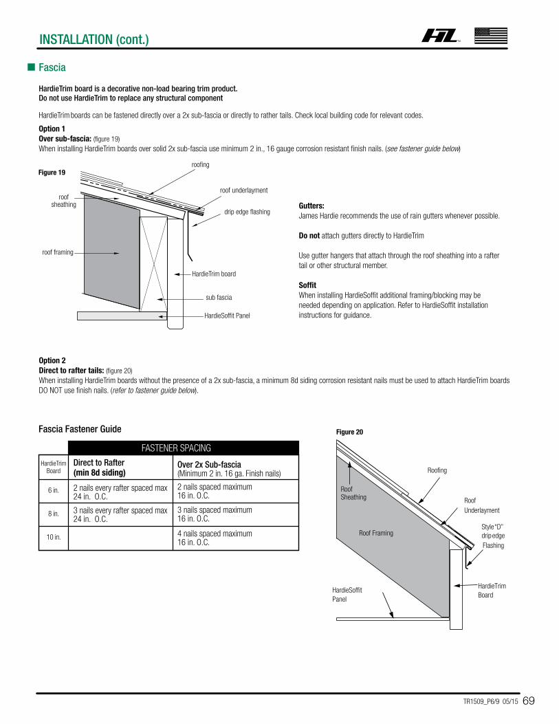
69TR1509_P6/9 05/15
HardieTrim board is a decorative non-load bearing trim product.
Fascia
Figure 19
roof sheathing
roof framing
roofing
roof underlayment
drip edge flashing
HardieTrim board
sub fascia
HardieSoffit Panel
Do not use HardieTrim to replace any structural component
HardieTrim boards can be fastened directly over a 2x sub-fascia or directly to rather tails. Check local building code for relevant codes.
Option 1Over sub-fascia: (figure 19)When installing HardieTrim boards over solid 2x sub-fascia use minimum 2 in., 16 gauge corrosion resistant finish nails. (see fastener guide below)
Gutters:James Hardie recommends the use of rain gutters whenever possible.
Do not attach gutters directly to HardieTrim
Use gutter hangers that attach through the roof sheathing into a rafter tail or other structural member.
SoffitWhen installing HardieSoffit additional framing/blocking may be needed depending on application. Refer to HardieSoffit installation instructions for guidance.
Option 2Direct to rafter tails: (figure 20) When installing HardieTrim boards without the presence of a 2x sub-fascia, a minimum 8d siding corrosion resistant nails must be used to attach HardieTrim boards DO NOT use finish nails. (refer to fastener guide below).
HardieTrim Board
6 in.
8 in.
10 in.
Over 2x Sub-fascia(Minimum 2 in. 16 ga. Finish nails)
FASTENER SPACING
Direct to Rafter (min 8d siding)
2 nails every rafter spaced max 24 in. O.C.
3 nails every rafter spaced max 24 in. O.C.
2 nails spaced maximum 16 in. O.C.
3 nails spaced maximum 16 in. O.C.
4 nails spaced maximum 16 in. O.C.
Figure 20
Roofing
RoofUnderlayment
Style“D”dripedgeFlashing
HardieTrimBoard
HardieSoffit Panel
Roof Framing
RoofSheathing
INSTALLATION (cont.)
Fascia Fastener Guide
70
CaulkingFor best results use an Elastomeric Joint Sealant complying with ASTM C920 Grade NS, Class 25 or higher or a Latex Joint Sealant complying with ASTM C834. Caulking/Sealant must be applied in accordance with the caulking/sealant manufacturer’s written instructions. For best results use an Elastomeric Joint Sealant complying with ASTM C920 Grade NS, Class 25 or higher or a Latex Joint Sealant complying with ASTM C834. Caulking/Sealant must be applied in accordance with the caulking/sealant manufacturer’s written instructions.
ColorPlus Technology Caulking, Touch-up & Laminate
When repainting ColorPlus products, James Hardie recommends the following regarding surface preparation and topcoat application:• Ensure the surface is clean, dry, and free of any dust, dirt, or mildew• Repriming is normally not necessary• 100% acrylic topcoats are recommended• DO NOT use stain, oil/alkyd base paint, or powder coating on James Hardie Products.• Apply finish coat in accordance with paint manufacturers written instructions regarding coverage, application methods, and application temperature• DO NOT caulk nail heads when using ColorPlus products, refer to the ColorPlus touch-up section
Cut Edge TreatmentCaulk, paint or prime all field cut edges. James Hardie touch-up kits are required to touch-up ColorPlus products.
• Care should be taken when handling and cutting James Hardie ColorPlus products. During installation use a wet soft cloth or soft brush to gently wipe off any residue or construction dust left on the product, then rinse with a garden hose.• A finish nail is required for installing 4/4 and 5/4 HardieTrim boards. • Touch up nicks, scrapes and nail heads using the ColorPlus Technology touch-up applicator. Touch-up should be used sparingly. If large areas require touch-up, replace the damaged area with new HardieTrim board with ColorPlus Technology.• Laminate sheet must be removed immediately after installation. Nail head touch-up can be done before or after removal of the laminate sheet when using finish nails. The preferred method is to touch-up while the laminate sheet is in place. Remove the laminate sheet before paint dries.• Terminate non-factory cut edges into trim where possible, and caulk. Color matched caulks are available from your ColorPlus product dealer.• Treat all other non-factory cut edges using the ColorPlus Technology edge coaters, available from your ColorPlus product dealer.
Note: James Hardie does not warrant the usage of third party touch-up or paints used as touch-up on James Hardie ColorPlus products.
Problems with appearance or performance arising from use of third party touch-up paints or paints used as touch-up that are not James Hardie touch-up, will not be covered under the James Hardie ColorPlus Limited Finish Warranty.
TR1509_P9/9 03/15
Additional Installation Information, Warranties, and Warnings are available at
www.jameshardie.com
© 2015 James Hardie Building Products. All rights reserved.TM, SM, and ® denote trademarks or registered trademarks of James Hardie Technology Limited. is a registered trademark of James Hardie Technology Limited.
RECOGNITION: HardieTrim boards may be installed as an equal alternative to conventional trim permitted for use in; 2006, 2009, & 2012 International Building Code, Section 1402.1, and the 2006, 2009, & 2012 International Residence Code for One - and Two - Family - Dwellings, Section R703.1.
Painting James Hardie Siding and Trim Products with ColorPlus Technology
FINISHING
PaintingDO NOT use stain, oil/alkyd base paint, or powder coating on James Hardie Products. James Hardie products must be painted within 180 days for primed product and 90 days for unprimed. 100% acrylic topcoats are recommended. Do not paint when wet. For application rates refer to paint manufacturers specifications. Back-rolling is recommended if the siding is sprayed.

71