general discussion of corrosion monitoring considerations ... · pdf filegeneral discussion of...
TRANSCRIPT

Rohrback Cosasco Systems, Inc. 11841 East Smith Avenue Santa Fe Springs, CA 90670 Tel: +1 (562) 949-0123 Fax: +1 (562) 949-3065 www.rohrbackcosasco.com
General Discussion of Corrosion Monitoring Considerations in Pipeline Design
Figures I, and II, show the basic layouts of which a pipeline system might consist. Figure I shows a system consisting of a line section transporting product from one tank storage farm to another. Figure II shows transport from an underground storage, or production, reservoir to a tank storage farm. Obviously, there are many possible variations. Branch lines may join the main line at several places. The product transported may be oil, in which case there will be booster stations along the length of the line or, the product may be gas, in which case the intermediate stations will be compressor stations. Product from the storage / production reservoir may go straight into the pipe line, or it may go into tank storage, prior to transport down the line. Irrespective, the basic principles of the corrosion monitoring system will be the same. In essence, the places that require corrosion monitoring are those locations at which water may accumulate, and stay in contact with the pipe / vessel wall for extended time periods. Additionally, corrosion monitoring is needed at those locations where some physical change in the system occurs that may cause a change in the downstream corrosion behavior. These various monitoring locations can be subdivided according to whether the purpose is to monitor internal, or external corrosion, and whether or not the monitoring location is above ground, or buried. Above ground locations are invariably ones that will be required for internal corrosion monitoring. All such locations are best monitored using the Microcor® technique. This is a high resolution version of the electrical resistance technique, which makes it sufficiently rapid so as to follow the corrosion at speeds approaching real time. The basis of the technique is measurement of the change in electrical resistance of a sensing element that is immersed in the process fluid. The electrical resistance of the element will increase, as its thickness is reduced by corrosion. The increase in electrical resistance is translated into a metal thickness loss that, with reference to time, can be expressed as a corrosion rate. Background information on the Microcor® Technique is provided in attachment I of this document. The Microcor® probe is inserted into the system, using the Cosasco 2”, access system that will permit probe insertion, and removal, without system depressurization or

2
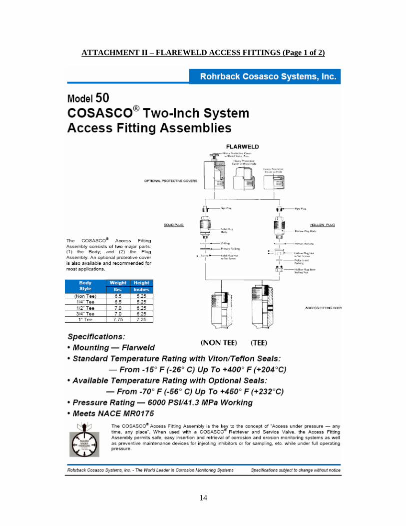
shutdown. Details on the access fitting assemblies, and associated retrieval tools & valves are given in attachment II & III of this document. The above ground locations that are of primary interest for internal corrosion monitoring are:
1. Internal Tank Bottoms:
Because of the comparatively long, static, residence time, water will tend to separate from the product, and accumulate in a layer at the bottom of the tank. The tank bottom will, therefore, be permanently wetted with potentially corrosive liquid. Irrespective of the source of water in the product, it will contain some dissolved salts, possibly dissolved oxygen, H2S, and CO2. It will be, to some extent corrosive, and require monitoring to assess the need for remediation.
2. Separator Inlet from Storage / Production Reservoir:
Fluid coming from a production, or storage, reservoir may contain suspended solids, sulfate reducing bacteria, and a variety of other corrosive constituents such as produced brine, and dissolved acid gases (H2S, and CO2), all of which can cause excessive corrosion in the separator, and throughout the pipeline system.
3. Downstream of Compressor / Booster Systems:
The outlet of any gas compression system will be an area in which entrained water droplets, or water vapor will condense, to produce liquid water, with the potential to produce excessive corrosion. The immediate area downstream of oil booster systems can be subject to turbulent flow conditions that can produce erosion damage.
4. Junctions with Joining Pipelines:
These junctions, that are not illustrated in figures I, and II, are locations at which process fluid of unknown quality joins the main pipeline. There is the potential for ingress of corrosive fluids at such junctions and, if accessible above ground, these should be monitored using the same Microcor® technique, with access through a Cosasco 2” access point.
5. Downstream of Chemical Injection points:
At any location where chemicals (corrosion inhibitors, biocides, oxygen scavengers) are injected into the system in order to remediate the effects of corrosion, a corrosion monitoring point should be installed. This point should be located at least 5-10 ft. downstream of the injection point. This is in order to monitor the effectiveness of the chemical injection in remediation of corrosion.

3
Such locations, if accessible above ground, should be monitored using the same Microcor® technique, with access through a Cosasco 2” access point.
All of the various locations mentioned above will comprise the same basic monitoring point, as illustrated in figure III. A 2”, flarweld access fitting, with a profiled base sized to fit the line diameter in question, is welded to the line. Normally, the access point will be installed at the 6-o’clock position on the line, so that it will “see” any small amounts of water that are flowing along the bottom of the line – in the case of tank bottoms, the fitting should be located close to the tank bottom. It should be remembered that each of these access points should be positioned such as to allow a clearance beyond the end of the fitting to permit use of the retrieval tool & service valve, during retrieval operations. The access fitting body will contain a hollow plug that carries the Microcor® probe. The probe itself is sized such that the sensing element will be flush with the inner wall of the line. The Microcor® probe is connected, via a permanently installed probe adapter, directly to a locally mounted, digital transmitter. The transmitter is, in turn, connected to a locally mounted data logging unit, via an armored cable. The data logging unit has an onboard battery system that powers both the data logger, and transmitter. The whole installation is certified explosion proof for use in Class I, Division I hazardous locations. The transmitter will read the Microcor® probe at a preprogrammed time interval. This time interval is selectable from as little as 1 minute, to as great as 24 hours. Typically a reading interval of once every four hours is sufficient for optimum data quality, and battery life; although, if very small corrosion rates prevail, the reading interval may be increased to a 24 hour frequency, extending battery life, without loss of data quality. The readings taken by the transmitter are stored in the adjacent data logger, in a time & date stamped format.
The transmitter, and data logging units are programmed using a CorrData® Mate hand terminal, that is loaded with the Microcor® Utilities program – when loaded with the Microcor® Utilities program, the CorrData® Mate is re-designated the “MicroMate”. The data logger / transmitter is programmed with the element type, and thickness, and the required reading interval, at which point it will begin monitoring & storing data points. At convenient intervals, the data from the data loggers is downloaded to the MicroMate hand terminal. This same data is subsequently uploaded to a PC configured with CorrData® Plus, corrosion data management software, augmented with the Microcor® Utilities program. The uploaded data is stored, by monitoring location, in a data base, and can be displayed as a spread sheet for detailed numerical analysis. The data from individual monitoring locations can also be displayed as a time based graphic of either metal loss, or corrosion rate, giving a visual display of metal-loss, and corrosion rate versus time. When viewed in conjunction with the onboard event report record, the graphic can be used to correlate corrosion excursions with specific operational changes and, as such, can be used to optimize corrosion behavior in the system.

4
Buried monitoring locations may serve the purpose of monitoring internal corrosion at points within the pipeline system where the gradient of the line changes from a negative value, to a positive value, with sufficient abruptness as to cause an accumulation of liquid water, and extended periods of exposure to corrosive conditions. Such a condition is illustrated below; however the gradient change is exaggerated for emphasis:
These locations are essentially inaccessible on a routine basis. Therefore, the installation of a consumable sensor, such as a Microcor® probe, requiring access every 18-24 months for replacement, is impractical. In these instances the Ultracorr®, high-resolution, ultrasonic sensor can be permanently installed directly on the pipeline exterior, and wired back to an above ground test post, as illustrated in figure IV. Since the Ultracorr® sensor is not consumable, access to the sensor, subsequent to initial installation, is not necessary. The Ultracorr® sensor, being a permanently installed device, with temperature compensation, achieves a practical resolution of c. 0.2 -0.4 mils and, as such, can detect corrosion rates of as little as 1 mpy in 60 -120 days, and significant corrosion rates in 10-30 days. Consequently, the response speed of the technique, unlike that of conventional ultrasonic sensors, is sufficient to provide a means to monitor, and control, excessive corrosion during the routine on-going operation of the pipeline. Detailed specifications for the Ultracorr® system are given in attachment IV of this document. The Ultracorr® sensors are usually used in a multiple array, distributed ± 150 about the 6-o’clock position on the line, as illustrated below:
Pipeline
Product Flow
Retained Water
Negative Gradient Positive Gradient

5
Each of the sensors is wired back to an above ground test post provided with three separate connectors for connection to the measurement instrument. The measurement instrument used in this case is a portable unit, with onboard memory. This permits the operators to take readings from a series of a test post locations, storing the data by location i.d. The data collected can subsequently be uploaded to the CorrData® Plus software, for storage by monitoring location, in a date / time stamped format. The data, thus stored, can be displayed in the same modes as that for the Microcor® data, providing spread sheet format, and graphics of metal loss, and corrosion rate, versus time. External corrosion on buried sections of the line can also be measured at the same locations, as those used for measurement of internal corrosion. These locations are suitable for measurement of external corrosion since, being low points in the pipe line, are also the locations where the surrounding soil / backfill is likely to be wetted for extended time periods. This external corrosion can be measured by including a conventional electrical resistance probe (model 650 – see attachment V)) in the backfill of the line, within 2-3 inches of line, in the same excavation used for installation of the Ultracorr® probes. The model 650 probe is wired back to the same test post as the Ultracorr® probe, as illustrated in figure IV. At the test post, the model 650 probe is either left floating, if the pipe line does not have a cathodic protection system installed, in which case it will measure the natural corrosivity of the soil. However, if a cathodic protection system is installed, the 650 probe element is shorted to the pipeline, at the test post, enabling the efficiency of the cathodic protection system to be measured. The Ultracorr® probe is directly measured by the CorrData® Mate II portable instrument, which is the same instrument used for measurement of Microcor® Data loggers, but configured with conventional CorrData® Plus software. The data thus
c. 150 c. 150
To Test Post
Pipeline
Ultracorr Sensor

6
collected can be uploaded to the PC and stored, and displayed / stored in the way as is done for the Microcor® , and Ultracorr® Data. The whole system can be envisioned as shown below:
This approach will permit above grade locations at potential risk of internal corrosion, and buried locations at risk of both internal, and external, corrosion to be monitored with a minimum of instrumentation variations, and using a single corrosion data management system. The foregoing is a general discussion of pipeline design considerations. Please contact Customer Service at Rohrback Cosasco Systems for more information at [email protected] or +1-562-949-0123. Visit online at www.rohrbackcosasco.com.
Buried Ultracorr Installation for Internal Monitoring
Above ground Microcor Data Logger Installations for
Internal Corrosion Monitoring
Buried Corrosometer probes for external Corrosion
Monitoring
CorrData Mate II, configured with Microcor Utiliities, for data logger
download
CorrData Mate II, configured for direct
reading of Corrosometer Probes
Ultracorr portable instrument for direct reading of probes
Typical Data
Output

7
Figure I - Generic Pipeline System
Figure II – Generic Pipeline System
Storage Tank Farm
Booster / Compressor Station
Booster / Compression Station
Ground Level Buried Line
Microcor Ultracorr E/R Underground
Storage / Production Reservoir
Separation Train
Flow
Storage Tank Farm Storage Tank Farm
Booster / Compressor Station
Booster / Compression Station
Ground Level Buried Line
Microcor Ultracorr E/R Underground
Flow

8
FIGURE III – TYPICAL ABOVE GROUND INTERNAL MONITORING POINT
MT-9485 Microcor Digital
Transmitter
Data Download To CorrData Plus
ML-9500B Microcor Data
Logger
CDM2-2-2. MicroMate
Hand Terminal
50-211-0-XX-K03504-1. 2” access ftg. body, for an
XX” line, in carbon steel, C/w hollow plug in AISI 316 stainless steel, and
cover with hole, in carbon steel.
M4700-S10-K03005-XX. Microcor probe in AISI 316 stainless steel, with 10 mil flush element in carbon steel
745093. Permanent probe adaper in AISI 316
stainless steel
748202-10. Transmitter-to-data logger cable 10 ft.
Typical Data Output

9
FIGURE IV - TYPICAL BURIED MONITORING POINT
GROUND LEVEL
650-1-T50-K03005-50. Underground Corrosometer probe
UST-IT-1-1-50. High sensitivity, ultrasonic sensor with 50 ft. cable.
TP-1P-3U-G. Test Post
Pipe Ground
Corrosometer Probe
UT Sensor # 1
UT Sensor # 2
UT Sensor # 3
Test Post Terminations
PIPELINE
Data Download to CorrData Plus
Typical Data
Output
CDM2-2-2. MicroMate / CorrData Mate II Hand Terminal
BACKFILL

10
ATTACHMENT I – Microcor® EQUIPMENT (Page 1 of 4)

11

12
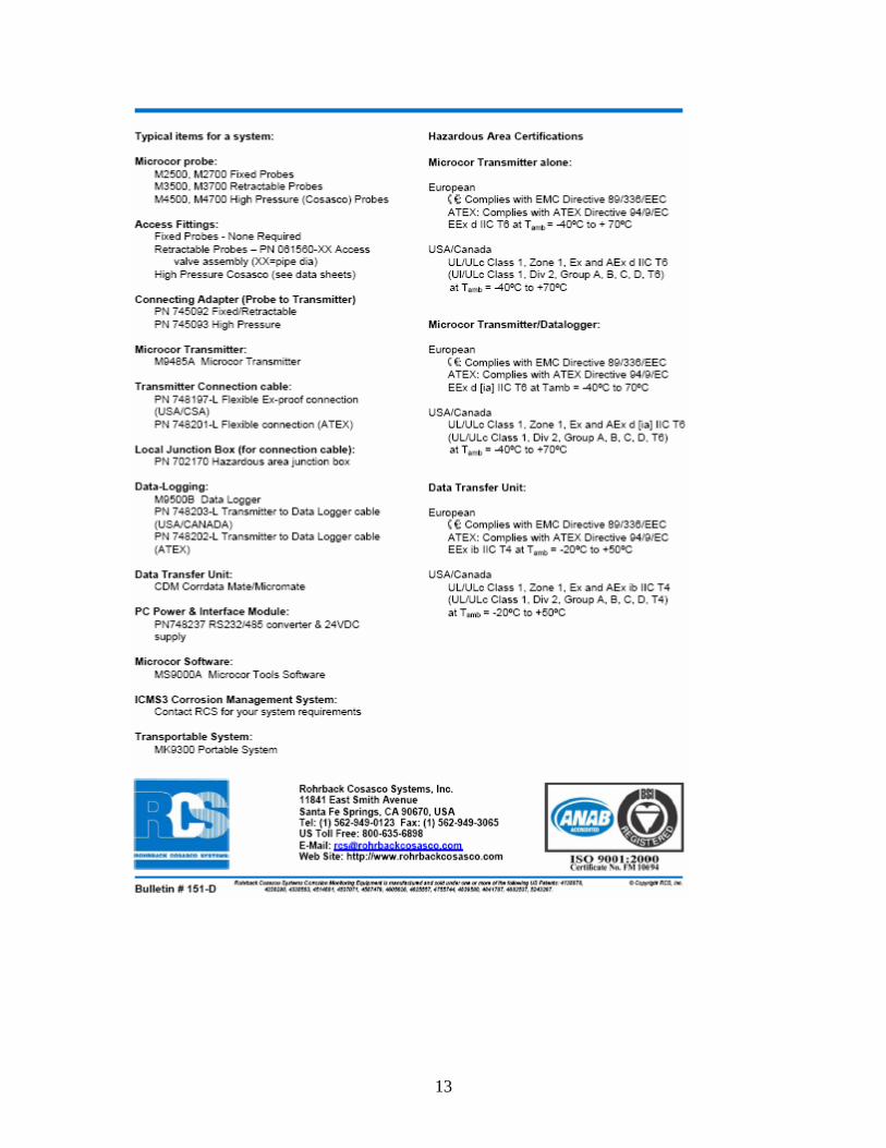
13
14
ATTACHMENT II – FLAREWELD ACCESS FITTINGS (Page 1 of 2)

15

16
ATTACHMENT III – RETRIEVAL TOOLS & SERVICE VALVES (Page 1 of 4)

17

18

19

20
ATTACHMENT IV- ULTRACOR SYSTEM (Page 1 of 2)

21

22
ATTACHMENT V – UNDERGROUND PROBE (Page 1 of 2)

23

24
ATTACHMENT VI – CORRDATA® PLUS CORROROSION DATA MANAGEMENT SOFTWARE (Page 1 of 2)

25