general contents - northern industrial · 2 general contents section page 4 technical...
TRANSCRIPT
1
Dialogue 5
General Contents
Section Page1 Introduction
Contents 3
1.1 Documentation Presentation 4
1.2 Module Description 5
1.3 Hardware Presentation 7
1.4 Hardware Installation 9
2 Software Installation
Contents 13
2.1 General 15
2.2 COM Word Service 16
2.3 Text Block Reminders 26
2.4 UNI-TE Services 32
2.5 Application-to-Application Communication 39
2.6 Priority Communication - Telegram 43
2.7 PLC Scan Cycle 49
2.8 Multiple Network Configurations 50
3 Maintenance
Contents 53
3.1 Troubleshooting 54
3.2 Self-Tests and Specific Tests 59
3.3 Data-Rate Control 62
2
General Contents
Section Page4 Technical Specifications
Contents 63
4.1 Performance 64
5 Appendix
Contents 73
5.1 Module Design 74
5.2 TSX Series 7 V3 PLC Special Points 78
5.3 Uni-TE Read Requests 80
5.4 Uni-TE Write Requests 98

3
Introduction 1
Introduction Section 1
Sub-section Page
1.1 Documentation Presentation 4
1.2 Module Description 5
1.2-1 General 51.2-2 Module Features 6
1.3 Hardware Presentation 7
1.3-1 TSX MAP 1074 Module 71.3-2 TSX MAP ACC1 Terminal Block 8
1.4 Hardware Installation 9
1.4-1 Installing the Module in the Rack 91.4-2 Coding the Address in the Terminal Block 101.4-3 Connection to the Network 11
4
1.1 Documentation Presentation
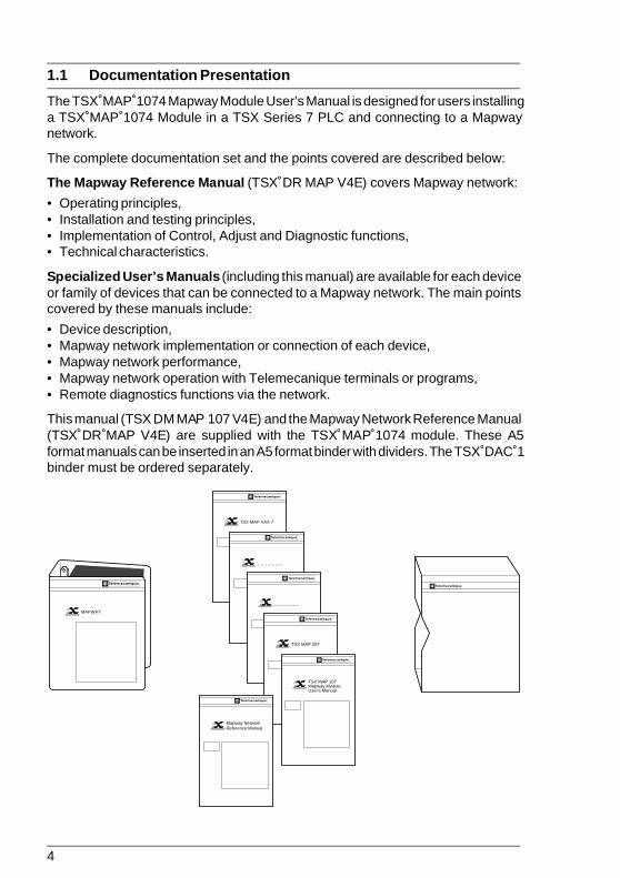
The TSX MAP 1074 Mapway Module User’s Manual is designed for users installinga TSX MAP 1074 Module in a TSX Series 7 PLC and connecting to a Mapwaynetwork.
The complete documentation set and the points covered are described below:
The Mapway Reference Manual (TSX DR MAP V4E) covers Mapway network:
• Operating principles,• Installation and testing principles,• Implementation of Control, Adjust and Diagnostic functions,• Technical characteristics.
Specialized User’s Manuals (including this manual) are available for each deviceor family of devices that can be connected to a Mapway network. The main pointscovered by these manuals include:
• Device description,• Mapway network implementation or connection of each device,• Mapway network performance,• Mapway network operation with Telemecanique terminals or programs,• Remote diagnostics functions via the network.
This manual (TSX DM MAP 107 V4E) and the Mapway Network Reference Manual(TSX DR MAP V4E) are supplied with the TSX MAP 1074 module. These A5format manuals can be inserted in an A5 format binder with dividers. The TSX DAC 1binder must be ordered separately.
TSX MAP VAX 7
†
MAPWAY
†
†
†
_ _ _ _ _ _ _
†
_ _ _ _ _ _ _
†
TSX MAP 207
†
TSX MAP 107 Mapway Module User's Manual
†
Mapway Network Reference Manual

5
Introduction 1
1.2 Module Description
1.2-1 General
The TSX MAP 1074 module is an intelligent module for use with TSX Series 7modular PLCs. It can be installed in TSX Series 7 Model 40 PLCs (TSX 47-40,TSX 67-40, TSX 87-40 and TSX 107-40 PLCs) with the following processormodules:• TSX P47-420,• TSX P67-410/420,• TSX P87-410/420,• TSX P107-410/420,
and in TSX Series 7 V3 PLCs:• TSX 47-31,• TSX 67-21,• TSX 87-31.
The module can be used for communication between the PLC and other devices inan X-WAY automation system.
These devices include:
• Telemecanique modular PLCs described above,• Telemecanique TSX T607 or TSX T407 programming terminals connected to the
programming port of a PLC on the network,• Telemecanique FTX 507 workstations directly connected to the network or
connected to the programming port of a PLC on the network,• IBM PC or compatible microcomputers equipped with a PC-AT (ISA) bus,• Telemecanique Monitor 77 supervision systems,• Digital Equipment Corporation (DEC) MicroVAX and IVAX minicomputers,• NUM robot or machine tool numerical controllers.
The network interfaces required depend on the device to connect to Mapway:
• TSX MAP 1074 module for PLCs,• TSX MAP PC74 interface board for FTX 507, Monitor 77 and all IBM PC and
compatible microcomputers,• TSX MAP VAX74 or TSX VAX174 interface boards for DEC MicroVAX and IVAX
minicomputers.
This manual describes the TSX MAP 1074 module for use with TelemecaniquePLCs.
6
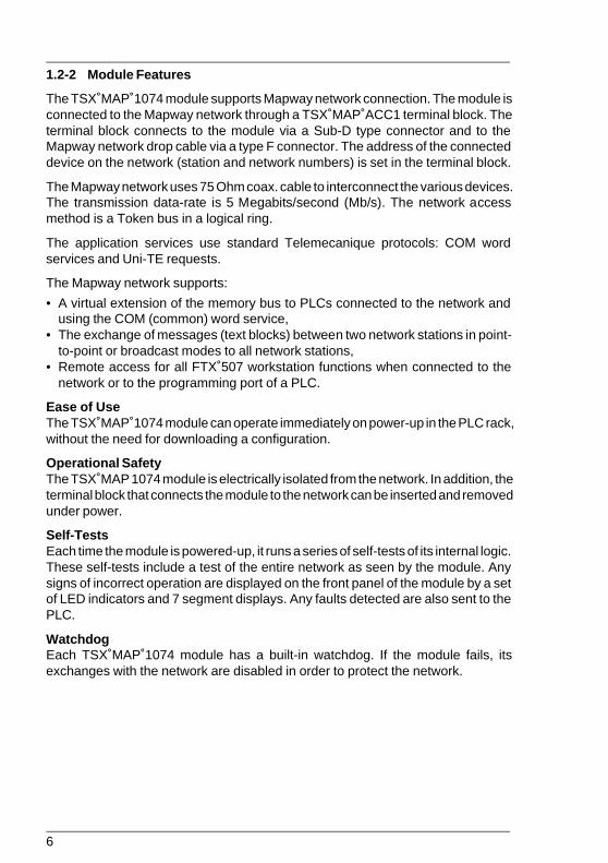
1.2-2 Module Features
The TSX MAP 1074 module supports Mapway network connection. The module isconnected to the Mapway network through a TSX MAP ACC1 terminal block. Theterminal block connects to the module via a Sub-D type connector and to theMapway network drop cable via a type F connector. The address of the connecteddevice on the network (station and network numbers) is set in the terminal block.
The Mapway network uses 75 Ohm coax. cable to interconnect the various devices.The transmission data-rate is 5 Megabits/second (Mb/s). The network accessmethod is a Token bus in a logical ring.
The application services use standard Telemecanique protocols: COM wordservices and Uni-TE requests.
The Mapway network supports:
• A virtual extension of the memory bus to PLCs connected to the network andusing the COM (common) word service,
• The exchange of messages (text blocks) between two network stations in point-to-point or broadcast modes to all network stations,
• Remote access for all FTX 507 workstation functions when connected to thenetwork or to the programming port of a PLC.
Ease of UseThe TSX MAP 1074 module can operate immediately on power-up in the PLC rack,without the need for downloading a configuration.
Operational SafetyThe TSX MAP 1074 module is electrically isolated from the network. In addition, theterminal block that connects the module to the network can be inserted and removedunder power.
Self-TestsEach time the module is powered-up, it runs a series of self-tests of its internal logic.These self-tests include a test of the entire network as seen by the module. Anysigns of incorrect operation are displayed on the front panel of the module by a setof LED indicators and 7 segment displays. Any faults detected are also sent to thePLC.
WatchdogEach TSX MAP 1074 module has a built-in watchdog. If the module fails, itsexchanges with the network are disabled in order to protect the network.

7
Introduction 1
1.3 Hardware Presentation
1.3-1 TSX MAP 1074 Module
The TSX MAP 1074 module is a single height module that can be installed in anyslot of the basic PLC rack in a PLC configuration.
The module comprises:
1 A metal case that protects theelectronics of the module andensures shielding from inter-ference.
2 A green "RUN" LED that lightswhen the module is powered-up and operating normally.
3 A red "DEF" (fail) LED thatlights when a module fault isdetected.
4 Three yellow LEDs that indi-cate the status of the modulein relation to the Mapway net-work:• INR: Station in the logical
ring,• RX: Station receiving data,• TX: Station transmitting
data.
5 Two 7 segment LED displaysfor displaying module operat-ing data.
6 A female Sub-D 11-point con-nector.
7 Two mounting screws that re-tain the module in the rack.
The rear panel of the module is equipped with factory-coded locating devices whichprevent any risk of error when modules are installed.
MAP 107
TX
NET
INR
RX
RUN
DEF
7
2
4
5
6
1
3
7
8
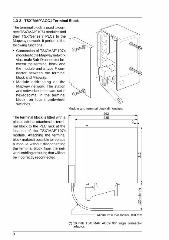
1.3-2 TSX MAP ACC1 Terminal Block
The terminal block is used to con-nect TSX MAP 1074 modules andtheir TSX Series 7 PLCs to theMapway network. It performs thefollowing functions:
• Connection of TSX MAP 1074modules to the Mapway networkvia a male Sub-D connector be-tween the terminal block andthe module and a type F con-nector between the terminalblock and Mapway,
• Module addressing on theMapway network. The stationand network numbers are set inhexadecimal in the terminalblock, on four thumbwheelswitches.
The terminal block is fitted with aplastic tab that attaches the termi-nal block to the PLC rack at thelocation of the TSX MAP 1074module. Attaching the terminalblock makes it possible to replacea module without disconnectingthe terminal block from the net-work cabling ensuring that will notbe incorrectly reconnected. 21
212
0 m
in. (
*)
2
262235
Minimum curve radius: 100 mm
Module and terminal block dimensions
(*) 18 with TSX MAP ACC9 90° angle connectoradaptor.

9
Introduction 1
1.4 Hardware Installation
1.4-1 Installing the Module in the Rack
TSX Series 7 Model 40 PLCs:
TSX 47-40 Slots 0 to 7 1 module max.
TSX 67-40 Slots 0 to 7 2 modules max.
TSX 87-40 Slots 0 to 7 4 modules max.
TSX 107-40 Slots 0 to 7 4 modules max.
TSX Series 7 V3 PLCs:
TSX 47-31 Slots 0 to 7 1 module max.
TSX 67-21 Slots 0 to 7 1 module max.
TSX 87-31 Slots 0 to 7 1 module max.
Note: Regardless of the type of PLC used, TSX MAP 1074 modules can only be installed inthe main configuration rack.
Hardware and software codes
Hardware code
A two figure decimal code that is set on the locating 13devices on the rear of the module.
Software code
A decimal code entered from the programming terminal Model 40: 13with the I/O configuration of the PLC. V3 PLCs: 12
Network installationThe network cables, tap junctions and other components should be installedaccording to the procedures described in the Mapway Network Reference Manual(TSX DR MAP V4E).

10
B1
00
net
st
Net
wor
k 00
Sta
tion
1B
1.4-2 Coding the Address in the Terminal Block
The thumbwheel switches are accessed byremoving the side cover of the terminal block.Once this is done, it is possible to remove thecircuit board that supports the four thumbwheelswitches and the type F connector.
Each station in a network layout is assigned adouble identification number:
• STAT: The station number on the network. Itcan take a value from 0 to 3F (for a total of 64stations),
• NET: The network number. It can take avalue from 0 to 7F.
This double number is coded in Hexadecimalby the four thumbwheel switches in the termi-nal block, as shown in the example below. AMapway network can comprise up to 64 sta-tions per network segment.
Example
The coding shown on the thumbwheel switches illustrated above corresponds to theaddress of station 27 (H’1B’) on network 3 (H'03').
Reminder: The addressing principles and the operation of the Mapway network are de-scribed in section 3 of the Mapway Network Reference Manual(TSX DR MAP V4E). Network number 0 is reserved for single network layouts. Inmultiple network layouts, network numbers 1 to H'7F' should be used.

11
Introduction 1
1.4-3 Connection to the Network
Once the module is installed in the PLC rack and the terminal block with the addresscoding is connected to it and the network, then the module is connected to theMapway network.
When the PLC is powered-up, all of the LEDs on the module light momentarily andthe self-tests start. The “RUN” LED blinks while the self-tests are in progress andremains lit once they are completed correctly. This LED shows that the module isoperating correctly.
The “RUN” LED is extinguished if the module watchdog is triggered and the modulebecomes idle.
The “INR” (IN Ring) LED shows that the TSX MAP 1074 module is connected to theMapway network and is active in passing the token on the bus. This means that themodule is ready to send and receive messages.
The “INR” LED remains off during the self-test phase and it only lights once theseare completed successfully. Until this LED lights, the module can only receivemessages, it cannot transmit on the network.
The “RX” and “TX” LEDs show that the TSX MAP 1074 module has detected datareception (RX) or transmission (TX) activity on the network.
The 7 segment LED displays are used to display different types of information. Whilethe module is operating normally, they display two types of information at twosecond intervals:
• The network number with a decimal point atthe lower right of the display, e.g. network 2,
• The station number without a decimal point,e.g. station 1A.
If a fault occurs during the self-test phase or during normal operation, the displayswill show an error code. Refer to section 3, Maintenance, for further information.

12

13
Software Installation 2
Software Installation Section 2
Sub-section Page
2.1 General 15
2.1-1 Functions 152.1-2 Module Configuration 15
2.2 COM Word Service 16
2.2-1 General 162.2-2 Common Memory Organization 172.2-3 COM Words in Multiple Network Layouts 182.2-4 COM Word Configuration 202.2-5 System Bits and Words 222.2-6 Application Examples 24
2.3 Text Block Reminders 26
2.3-1 Description 262.3-2 Communication by TXT Text Block 262.3-3 Communication by SYS Text Block 302.3-4 Table Layout 31
2.4 UNI-TE Services 32
2.4-1 General 322.4-2 Server PLC 332.4-3 Client PLC 35
2.5 Application-to-Application Communication 39
2.5-1 Point-to-Point Messages 392.5-2 Broadcast Messages 402.5-3 Point-to-Point Message Example 41

14
Sub-section Page
2.6 Priority Communication - Telegram 43
2.6-1 General 432.6-2 Telegram Programming 452.6-3 Telegram Example 46
2.7 PLC Scan Cycle 49
2.8 Multiple Network Configurations 50
2.8-1 Module Configuration 502.8-2 PLC Cycle Time 51
Software Installation Section 2

15
Software Installation 2
2.1 General
2.1-1 Functions
The TSX MAP 1074 module supports the functions defined for the Mapway network.These functions include:
• Carrying UNI-TE messages from the PLC processor to the network and viceversa. This message system supports access to variables (all PL7 objects) forreading and writing, program transfer and PLC operating mode control,
• Application program to application program communication in point-to-pointmode from any station in the network layout to any other station, or broadcastmessages on the network,
• High priority fast communication between application programs (short 16 byteexchanges) between two PLCs on the same network, in the form of telegrams(TLG),
• Cyclic broadcasting of the distributed COM word data base between PLCs on thesame network,
• Overall network management, especially message routing between networks.
During each PLC cycle, 2 messages can be sent on the network in normal operation,up to four messages per cycle can be sent at peak load. In the same way, at the startof each PLC cycle, the PLC can receive two messages in normal operation (fourduring peaks) from the PLC.
The TSX MAP 1074 module can handle approx. 200 messages per second. Amessage is a COM field sent or received or a TXT, SYS or TLG text block sentor received.
2.1-2 Module Configuration
The TSX MAP 1074 module is automatically configured on power-up. The networknumber (0 to H’7F’) and the station number (0 to H’3F’) assigned, are those set inthe TSX MAP ACC1 terminal block.
The PLC will only recognize the TSX MAP 1074 module if it has been declared inthe I/O configuration. If the module is not declared, it can still send messages to thePLC system, e.g. for program downloading.
16
2.2 COM Word Service
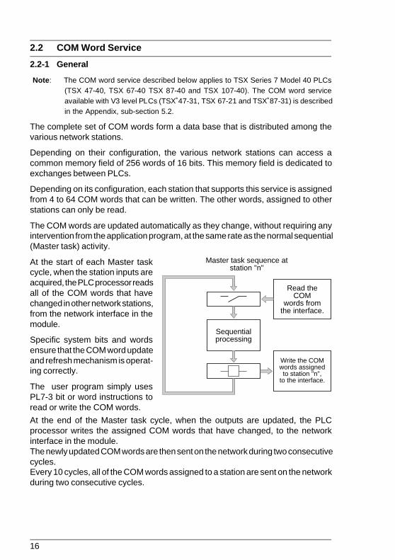
2.2-1 General
Note: The COM word service described below applies to TSX Series 7 Model 40 PLCs(TSX 47-40, TSX 67-40 TSX 87-40 and TSX 107-40). The COM word serviceavailable with V3 level PLCs (TSX 47-31, TSX 67-21 and TSX 87-31) is describedin the Appendix, sub-section 5.2.
The complete set of COM words form a data base that is distributed among thevarious network stations.
Depending on their configuration, the various network stations can access acommon memory field of 256 words of 16 bits. This memory field is dedicated toexchanges between PLCs.
Depending on its configuration, each station that supports this service is assignedfrom 4 to 64 COM words that can be written. The other words, assigned to otherstations can only be read.
The COM words are updated automatically as they change, without requiring anyintervention from the application program, at the same rate as the normal sequential(Master task) activity.
At the start of each Master taskcycle, when the station inputs areacquired, the PLC processor readsall of the COM words that havechanged in other network stations,from the network interface in themodule.
Specific system bits and wordsensure that the COM word updateand refresh mechanism is operat-ing correctly.
The user program simply usesPL7-3 bit or word instructions toread or write the COM words.
At the end of the Master task cycle, when the outputs are updated, the PLCprocessor writes the assigned COM words that have changed, to the networkinterface in the module.The newly updated COM words are then sent on the network during two consecutivecycles.Every 10 cycles, all of the COM words assigned to a station are sent on the networkduring two consecutive cycles.
Read the COM
words from the interface.
Write the COM words assigned to station "n",
to the interface.
Sequential processing
Master task sequence at station "n"

17
Software Installation 2
2 to 4
5 to 8
9 to 16
17 to 32
33 to 64
0 to 3
0 to 7
0 to H'0F'
0 to H'1F'
0 to H'3F'
64 max.
32 max.
16 max.
8 max.
4
Number of stations
Number of COM words
Station addresses
2.2-2 Common Memory Organization
Each TSX MAP 1074 module has a memory field of 256 words of 16 bits dedicatedto communication between PLCs. This memory field is split into sub-blocks ofwords. The number of stations that send COM words on the network and theiraddress determines the number of COM words available, as shown in the tablebelow:
Example with 64 stations:
COM 0,0
COM 0,1
COM 0,2
COM 0,3
COM 1,0
COM 1,1
COM 1,2
COM 1,3
COM 3F,0
COM 3F,1
COM 3F,2
COM 3F,3
Station 0
Station 1
Station 3F
0F

18
Each word in the memory can be accessed by the syntax COMi,j:
where i = station number (0 to H’3F’),j = word position (0 to H’3F’).
The internal program of TSX Series 7 PLCs enables access to the individual bits ofCOM words. In this case the syntax is COMi,j,k:
where i = station number (0 to H’3F’),j = word position (0 to H’3F’),k = bit position (0 to H’0F’).
The PLC user program:
• Writes data to be sent on the network to its own COM word field COMi,j,• Reads the data from a network station by reading from the COM word field COMi,j
assigned to each station.
2.2-3 COM Words in Multiple Network Layouts
In a multiple network layout, some PLCs are connected to two or more differentnetworks or network segments.
The common network field can therefore only be accessed by PLCs connected tothe same network segment. These PLCs therefore have access to two or morememory fields.
To distinguish between COM words from different networks the following syntax isused COMxi,j:
where x = logical network identifier,i = station number,j = word position.
The network logical identifier takes the value B, C or D depending on the numberof interface modules in the Bridge station. The identifier letter is dynamicallyassigned by the PLC processor, depending on the geographical location of theinterface module. Each identifier letter corresponds to a dedicated memory field thatis assigned to the designated network.

19
Software Installation 2
COMC0,0 COMC0,1 . . . . . COMC1,0 . . . . . COMC8,0 . . . . .
Network 3
V
COMB0,0 COMB0,1 . . . . . COMB1,0 . . . . . COMB8,0 . . . . .
Network 2
V
COM0,0 COM0,1 . . . . . COM1,0 . . . . . COM8,0 . . . . .
Network 1
V
7 6 5 4 3 2 1 0
M P W
M P W
M P W
Example
Network connected to the modulein slot 1: no identifier,
Network connected to the modulein slot 4: identifier B,
Network connected to the modulein slot 5: identifier C.
Memory field thatis common to thethree networksconnected to thePLC.
The network logical identifier does not correspond to a network number but to ageographical location. The PLC application program is independent of the networknumber. The user must ensure that in the application program, the logical identifierassigned by the PLC corresponds to the network that is actually connected to themodule.

20
2.2-4 COM Word Configuration
When a TSX MAP 1074 module is configured, it is possible to:
• Inhibit it from accessing COM words,• Validate COM word read-only access,• Validate COM word read and write access,• Declare the number of COM words (from 4 to 64) controlled by the station.
The number of COM words declared must be identical for all stations on the samenetwork. If the value configured for a station is incorrect, it will be ignored by theothers.
A station that reads and writes COM words sends its COM words on the networkand receives the COM words sent by other network stations.
An inactive station neither sends nor receives COM words. This function reducesnetwork traffic and the workload of each station.
A station that is active in read-only mode cannot send COM words on the networkbut can read those sent by other stations.
It is possible to configure a number of COM words that is less than the maximumallowed for each station. This feature must always be used when only limitedamounts of information need to be sent on the network. This considerably improvesCOM word processing time by the PLC.
Configuration procedure
The selection is made when the application is configured by an FTX 507 workstation(with PL7-3 language in Configuration mode).
After selecting the Configure Network Service action, a screen is displayed thatshows the following information for each module:
• Its type,• Its location in the PLC,
Allowing the user to change:
• The number of COM words assigned by the module (0 by default),• Whether or not COM words are active (inactive by default).

21
Software Installation 2
Note: When the TSX MAP 1074 module is not declared in the Input/Output configuration ofthe PLC, COM word exchange is not supported.
For more information on entering and configuring COM words using the program-ming terminals, refer to the PL7-3 Operating Modes manual (TXT DM PL7-3 V4E).
Configuring PLCs for Multiple Network Operation
Configuration of the COM words of multiple network PLCs, i.e. PLCs that have morethan one TSX MAP 1074 module is performed with the PL7-NET program. Thisprogram is part of the X-TEL Software Workshop.
Among other functions, this program enables:
• Selection of stations that form a network and assignment of station addresses,• Assignment for each Bridge station, of the modules connected to the various
networks.
For more information on how to use this program, refer to the PL7-NET Programdocumentation (TXT DM PL7 NET V4E).

22
2.2-5 System Bits and Words
Some system bits and words can be used by the user program for testing the correctoperation of the network and application coherence, with the PLC running and theMapway network interface operating. The following bits and words are used by thetest:
System Bit Description Function
SY11 COM word Normally at 0, this bit is set to 1 when a localrefresh station has received COM words from at least
one remote station.It is reset to 0 by program or by the terminal, sothat it can check other transmissions of COMwords.
SY12 Network A This bit is set to 1 once the network interfaceoperating of the station has exchanged COM words with at
least one other station on the network.It is reset to 0 by program or by the terminal, sothat it can check other transmissions of COMwords.
SY13 Network B as SY12operating
SY14 Network C as SY12operating
SY15 Network D as SY12operating

23
Software Installation 2
F 8 7 0
Network Nbr. Station Nbr.
Module
A
SW64 SW65 SW66 SW67
SW68 SW69 SW70 SW71
SW72
Module
B
SW73 SW74 SW75 SW76
SW77 SW78 SW79 SW80
SW81
Module
C
SW82 SW83 SW84 SW85
SW86 SW87 SW88 SW89
SW90
Module
D
SW91 SW92 SW93 SW94
SW95 SW96 SW97 SW98
SW99
System Words
Refresh Indicators (1 bit per station) Stations H'00' to H'0F', Stations H'10' to H'1F', Stations H'20' to H'2F', Stations H'30' to H'3F'. Reserved words, Reserved words, Reserved words, Reserved words. Module network address
Refresh indicators
The 16 bits of each word represent the 16 network stations. A bit at 1 indicates thatthe corresponding station has sent its COM words.
It is reset to 0 by program only, so that it can check other transmissions of COMwords.
Module network address
This word indicates the network number (0 to 127) and the station number (0 to 63)corresponding to each module, in the form of:
24
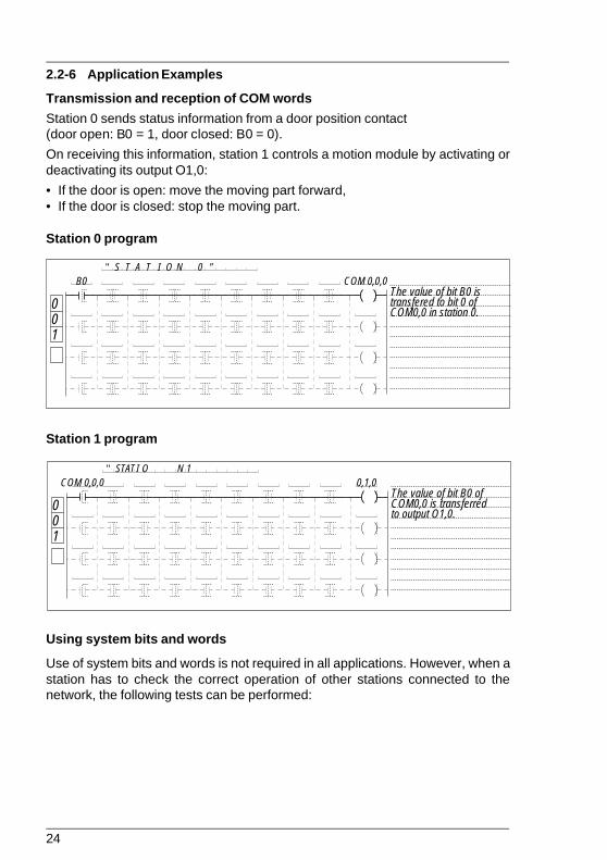
" S T A T I O N 0 "
001
COM 0,0,0B0The value of bit B0 istransfered to bit 0 ofCOM0,0 in station 0.
2.2-6 Application Examples
Transmission and reception of COM words
Station 0 sends status information from a door position contact(door open: B0 = 1, door closed: B0 = 0).
On receiving this information, station 1 controls a motion module by activating ordeactivating its output O1,0:
• If the door is open: move the moving part forward,• If the door is closed: stop the moving part.
Station 0 program
Station 1 program
Using system bits and words
Use of system bits and words is not required in all applications. However, when astation has to check the correct operation of other stations connected to thenetwork, the following tests can be performed:
" S T A T I O N 1 0,1,0 COM 0,0,0
0 0 1
The value of bit B0 of COM0,0 is transferred to output O1,0.
25
Software Installation 2
"
001
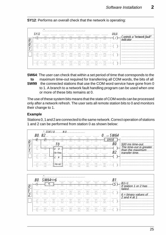
O0,0SY12Controls a "network fault"indicator/
SY12: Performs an overall check that the network is operating:
SW64: The user can check that within a set period of time that corresponds to theto maximum time-out required for transferring all COM words, the bits of all
SW99 the connected stations that use the COM word service have gone from 0to 1. A branch to a network fault handling program can be used when oneor more of these bits remains at 0.
The use of these system bits means that the state of COM words can be processedonly after a network refresh. The user sets all remote station bits to 0 and monitorstheir change to 1.
Example
Stations 0, 1 and 2 are connected to the same network. Correct operation of stations1 and 2 can be performed from station 0 as shown below:
of rred
"
0 1 2
B0 S
B1 B1=1 If station 1 or 2 has failed. 6 = binary values of 2 and 4 at 1
SW64<>6 <
" S T A T I O N 0 B0 B2
B0
B2
OPER 0 SW64 →
T0 500 ms time-out. The time-out is greater than the maximum transfer time.
E D
C R
TB=10ms
PR=50
0 1 1
26
2.3 Text Block Reminders
2.3-1 Description
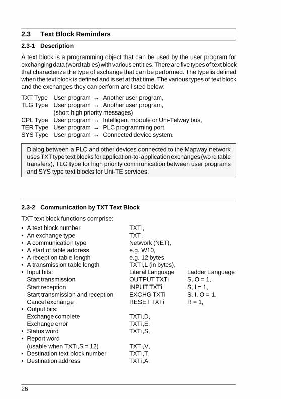
A text block is a programming object that can be used by the user program forexchanging data (word tables) with various entities. There are five types of text blockthat characterize the type of exchange that can be performed. The type is definedwhen the text block is defined and is set at that time. The various types of text blockand the exchanges they can perform are listed below:
TXT Type User program ↔ Another user program,TLG Type User program ↔ Another user program,
(short high priority messages)CPL Type User program ↔ Intelligent module or Uni-Telway bus,TER Type User program ↔ PLC programming port,SYS Type User program ↔ Connected device system.
Dialog between a PLC and other devices connected to the Mapway networkuses TXT type text blocks for application-to-application exchanges (word tabletransfers), TLG type for high priority communication between user programsand SYS type text blocks for Uni-TE services.
2.3-2 Communication by TXT Text Block
TXT text block functions comprise:
• A text block number TXTi,• An exchange type TXT,• A communication type Network (NET),• A start of table address e.g. W10,• A reception table length e.g. 12 bytes,• A transmission table length TXTi,L (in bytes),• Input bits: Literal Language Ladder Language
Start transmission OUTPUT TXTi S, O = 1,Start reception INPUT TXTi S, I = 1,Start transmission and reception EXCHG TXTi S, I, O = 1,Cancel exchange RESET TXTi R = 1,
• Output bits:Exchange complete TXTi,D,Exchange error TXTi,E,
• Status word TXTi,S,• Report word
(usable when TXTi,S = 12) TXTi,V,• Destination text block number TXTi,T,• Destination address TXTi,A.
27
Software Installation 2
The TXT text block function exchanges data as word tables that are organized asshown below:
• A transmission table comprising internal words (Wi) or constant words (CWi),• A reception table comprising internal words (Wi) that allow the destination station
to store the data received.
TXTi,D: This bit goes to 1 when the text block completes its exchange (refer to sub-section 3.3),
TXTi,E: This bit goes to 1 if an exchange error occurs (refer to sub-section 3.3),
TXTi,S: This word comprises the number of bytes received in the reception tableof the text block if the exchange is correct. If an exchange error occurs,TXTi,S takes the following values:1: Exchange cancelled by Reset,2: Transmission table length error,3: Mains failure (refer to sub-section 3.3),4: Module failure,5: Parameter error or too many active TXTs,6: Message received is too long,10: Incorrect addressing of the indirect text block,12: Message refused (refer to TXTi,V),13: Routing error,14: Resource error,20: Other error.
TXTi,V: If parameter TXTi,S is set to 12 (message refused), word TXTi,V indicatesthe type of refusal:1: Inadequate bus resources,2: Inadequate line resources,3: Cannot access destination,4: Line error,5: Length error,6: Network failure,7: Address error,8: Unknown request code,9: Inadequate PLC resources,10: Time-out exceeded,255: Other error.
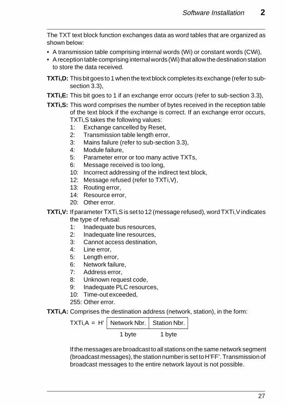
TXTi,A: Comprises the destination address (network, station), in the form:
TXTi,A = H’ Network Nbr. Station Nbr.
1 byte 1 byte
If the messages are broadcast to all stations on the same network segment(broadcast messages), the station number is set to H’FF’. Transmission ofbroadcast messages to the entire network layout is not possible.

28
The reception table length is set when the text block is configured. It cannot bechanged by the user program.
The address of the word table to send and of the reception table where the wordsreceived are stored can be specified in two ways:
• By direct addressing: the address is the first word of the table,• By indirect addressing: the address is stored in a table,
Direct addressingThe text block reception table is stacked on top of the transmission table as shownbelow. The start address (Addr. Buffer) and the length (Reception length) of thetable that is formed, are defined when the text block is configured.
The transmission table length is defined by the user program, in variable TXTi,L ofthe text block. It can be changed during program execution.
ExampleText block number TXT0,Start of table address: W10,Reception table length: 12 bytes,Transmission table length: TXT0,L = 8 bytes.
Special casesWhen the text block is only used to send data:
• The reception table length can be null,• The start of table address (Addr. Buffer) is also the transmission table address,• The table can be located in the internal words (Wi) or in the constant words (CWi).
ReceptionTable
TransmissionTable
Wi
Reception table length (in bytes):Reception Lengh
Start of table address: Addr. Buffer (Wi)
TXT0R
S
O
I
D
ETXTTM
T C OT,V OW1012 DT,L,8T,S ?
Transmission
ReceptionW10W11W12W13W14W15
W16W17W18W19
29
Software Installation 2
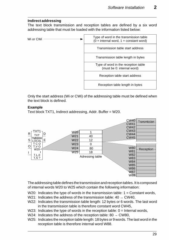
Indirect addressingThe text block transmission and reception tables are defined by a six wordaddressing table that must be loaded with the information listed below:
Only the start address (Wi or CWi) of the addressing table must be defined whenthe text block is defined.
ExampleText block TXT1, Indirect addressing, Addr. Buffer = W20.
The addressing table defines the transmission and reception tables. It is composedof internal words W20 to W25 which contain the following information:
W20: Indicates the type of words in the transmission table: 1 = Constant words,W21: Indicates the address of the transmission table: 40 → CW40,W22: Indicates the transmission table length: 12 bytes or 6 words. The last word
in the transmission table is therefore constant word CW45,W23: Indicates the type of words in the reception table: 0 = Internal words,W24: Indicates the address of the reception table: 80 → CW80,W25: Indicates the reception table length: 18 bytes or 9 words. The last word in the
reception table is therefore internal word W88.
Type of word in the transmission table(0 = internal word, 1 = constant word)
Transmission table start address
Transmission table length in bytes
Type of word in the reception table(must be 0: internal word)
Reception table start address
Reception table length in bytes
Wi or CWi
Reception
Transmission
TXT1R
S
O
I
D
E
TXT
LOCALT C OT,V OW20
IT,L,0T,S ?
1401208018
TM0000H
CW41CW42
CW40
CW43CW44CW45
W80W81W82W83W84W85W86W87W88
W20W21W22W23W24W25
Adressing table
30
2.3-3 Communication by SYS Text Block
The system (SYS) text block is used to communicate with certain system functionsof a device connected to Mapway (PLCs or other vendor’s device). This type ofcommunication uses Uni-TE requests.
SYS text blocks comprise:
• A text block number TXTi,
• An exchange type SYS,
• A communication type Network (NET),
• A start of table address e.g. W10,
• A reception table length e.g. 4 bytes,
• A transmission table length TXTi,L (in bytes),
• Uni-TE request code TXT,C,
• An exchange report TXTi,V,
• A destination address TXTi,A.
• A status word TXTi,S,
• Input bits: Literal Language Ladder LanguageStart transmission OUTPUT TXTi S, O = 1,Start reception INPUT TXTi S, I = 1,Start transmission and reception EXCHG TXTi S, I, O = 1,Cancel exchange RESET TXTi R = 1,
• Output bits:Exchange complete TXTi,DExchange error TXTi,E
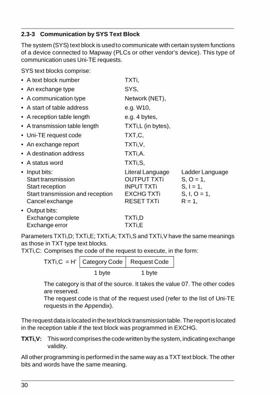
Parameters TXTi,D; TXTi,E; TXTi,A; TXTi,S and TXTi,V have the same meaningsas those in TXT type text blocks.TXTi,C: Comprises the code of the request to execute, in the form:
TXTi,C = H’ Category Code Request Code
1 byte 1 byte
The category is that of the source. It takes the value 07. The other codesare reserved.The request code is that of the request used (refer to the list of Uni-TErequests in the Appendix).
The request data is located in the text block transmission table. The report is locatedin the reception table if the text block was programmed in EXCHG.
TXTi,V: This word comprises the code written by the system, indicating exchangevalidity.
All other programming is performed in the same way as a TXT text block. The otherbits and words have the same meaning.
31
Software Installation 2
Example
TXTi,A = H’0105' corresponds to a destination station at address 5 on network 1,TXTi,C = H’0706' corresponds to a PLC sending the “read system word” request
(request code H’06').
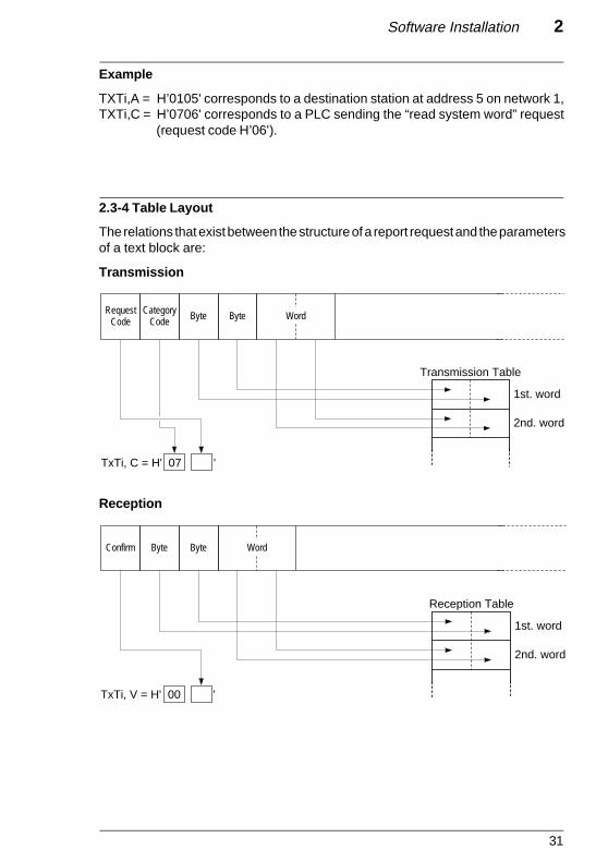
2.3-4 Table Layout
The relations that exist between the structure of a report request and the parametersof a text block are:
Transmission
Reception
RequestCode
CategoryCode Byte Byte Word
Transmission Table
1st. word
2nd. word
TxTi, C = H' 07 '
Byte Byte Word
TxTi, V = H' 00 '
Reception Table
1st. word
2nd. word
Confirm

32
2.4 Uni-TE Services
2.4-1 General
RemindersThis service uses a question and answer dialog called Request/Confirm.
A device that supports the Uni-TE protocol can be a:
CLIENT: This device initiates communication. It asks a question (reads), sendsan answer (writes) or an order (Run, Stop, etc.),
SERVER: This device executes the order sent by the client and sends a confirmafter execution.
The services supported depend on the type of device, e.g. PLC, numericalcontroller, programming terminal, supervision system. Depending on its function,each device can be a Client and/or a Server on the Mapway network. Serverfunctions include supporting Programming, Adjust and Debug functions while Clientfunctions include the user program sending commands or reading the state of adevice.
The rate at which Uni-TE requests can be handled by a PLC depends on the Mastertask cycle.
Regardless of where in the pro-gram a text block is activated, thePLC processor sends the appro-priate request at the end of thePLC cycle.
A check is made at the start ofeach cycle to determine if a con-firm was received for the request.
While the Master task is running,the PLC can send and receive twoTXT, SYS or TLG messages overMapway in normal operation andup to four messages in peaks.
ReadUni-TE
message
SequentialProcessing
WriteUni-TE
message
Master task cycleof station "n"
33
Software Installation 2
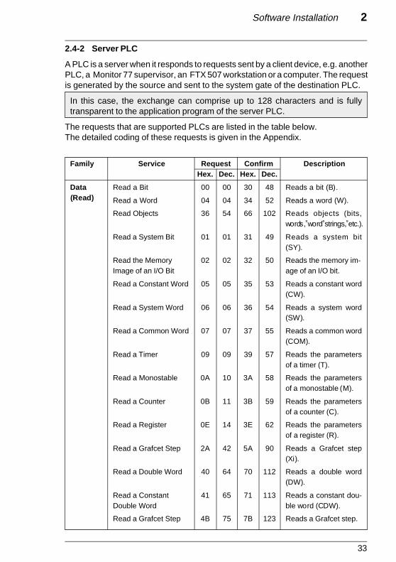
2.4-2 Server PLC
A PLC is a server when it responds to requests sent by a client device, e.g. anotherPLC, a Monitor 77 supervisor, an FTX 507 workstation or a computer. The requestis generated by the source and sent to the system gate of the destination PLC.
In this case, the exchange can comprise up to 128 characters and is fullytransparent to the application program of the server PLC.
The requests that are supported PLCs are listed in the table below.The detailed coding of these requests is given in the Appendix.
Family Service Request Confirm DescriptionHex. Dec. Hex. Dec.
Data Read a Bit 00 00 30 48 Reads a bit (B).
Read a Word 04 04 34 52 Reads a word (W).
Read Objects 36 54 66 102 Reads objects (bits,words, word strings, etc.).
Read a System Bit 01 01 31 49 Reads a system bit(SY).
Read the Memory 02 02 32 50 Reads the memory im-Image of an I/O Bit age of an I/O bit.
Read a Constant Word 05 05 35 53 Reads a constant word(CW).
Read a System Word 06 06 36 54 Reads a system word(SW).
Read a Common Word 07 07 37 55 Reads a common word(COM).
Read a Timer 09 09 39 57 Reads the parametersof a timer (T).
Read a Monostable 0A 10 3A 58 Reads the parametersof a monostable (M).
Read a Counter 0B 11 3B 59 Reads the parametersof a counter (C).
Read a Register 0E 14 3E 62 Reads the parametersof a register (R).
Read a Grafcet Step 2A 42 5A 90 Reads a Grafcet step(Xi).
Read a Double Word 40 64 70 112 Reads a double word(DW).
Read a Constant 41 65 71 113 Reads a constant dou-Double Word ble word (CDW).
Read a Grafcet Step 4B 75 7B 123 Reads a Grafcet step.
(Read)

34
Family Service Request Confirm DescriptionHex. Dec. Hex. Dec.
Data Write a Bit 10 16 FE 254 Writes a bit (B).
Write a Word 14 20 FE 254 Writes a word (W).
Write Objects 37 55 FE 254 Writes objects (bits,words, bit or wordstrings, etc.).
Write a System Bit 11 17 FE 254 Writes a system bit (SY).
Write the Memory 12 18 FE 254 Writes the memory im-Image of an I/O bit age of an I/O bit.
Write a System Word 15 21 FE 254 Writes a system word(SW).
Write a Common Word 16 22 FE 254 Writes a common word(COM).
Write a Timer Preset 17 23 FE 254 Writes the preset of atimer (T).
Write a Monostable 18 24 FE 254 Writes the preset of aPreset monostable (M).
Write a Counter Preset 19 25 FE 254 Writes the preset of acounter (C).
Write a Register Input 1A 26 FE 254 Writes the input of aregister (R).
Write a Double Word 46 70 FE 254 Writes a double word(DW).
Operating Run 24 36 FE 254 Sets a device to Run.
Stop 25 37 FE 254 Sets a device to Stop.
Note: Other requests are supported by PLCs. These requests are used for specificapplications and are not covered in this manual.
(Write)
Modes

35
Software Installation 2
Station 4 Station 0F
TSX 87-40 TSX 87-40
Network 1
SYS
2.4-3 Client PLC
A Client PLC sends data, an order or a question using Uni-TE requests.
The request is sent to the target station by a SYS type Network text block witha maximum length of 128 bytes.
The requests that can be sent by the PLC are:
• The requests described previously (for dialog between PLCs),• The requests supported by a destination station that is not a PLC, e.g. CNC,
MicroVAX computer. For further information refer to the documentation for theindividual devices giving their coding.
ExampleIn the network shown below (network 1), the PLC at address 4 reads the parametersof timer T10 of the PLC at address H'0F'. The PLC at address H'0F' does not requirea specific application program to allow the station access to its system.
Data
• Read timer request:• Request code = H’09' (see list of requests),• Parameter = Number of the timer to read.
• Text Block:• The request is sent by text block TXT5 of the application program in station 4,• Start of transmission table = W264. The transmission table comprises the
number of the timer (10),• Start of reception table = W200.

36
Transmission
• Station 4 Text block:
• TXT5 is a SYS type Network text block,• TXT5,A = H’010F’ Network 1, Target station H’0F’,• TXT5,C = H’0709' Category code = H’07', Request code = H’09',• TXT5,L = 2 (Length of the transmission table in bytes),• Transmission table:
Timer number
Reception
• Station 4 Text block:
• TXT5,V = H’39' Correct exchange confirm,• TXT5,D = 1,• TXT5,E = 0,• TXT5,S = 8 8 bytes received,• Reception table:
• Confirm analysis:
W200 = H’0002'
Least significant byte = 02 → 1 second time-base,Most significant byte = 00 → time-base not timed out.
W201 = H’0101'
Least significant byte = 01 → timer running,Most significant byte = 01 → preset can be changed.
W202 = 3600
The configuration preset value is 3600.
W203 = 1712
The current value when processing took place was 1712.
W264 10
W203 1712
W202 3600
W201
W200 00 02
0101
37
Software Installation 2
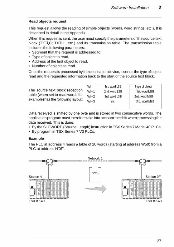
Read objects request
This request allows the reading of simple objects (words, word strings, etc.). It isdescribed in detail in the Appendix.
When this request is sent, the user must specify the parameters of the source textblock (TXTi,C; TXTi,L, etc.) and its transmission table. The transmission tableincludes the following parameters:• Segment that the request is addressed to,• Type of object to read,• Address of the first object to read,• Number of objects to read.
Once the request is processed by the destination device, it sends the type of objectread and the requested information back to the start of the source text block.
The source text block receptiontable (when set to read words forexample) has the following layout:
Data received is shifted by one byte and is stored in two consecutive words. Theapplication program must therefore take into account the shift when processing thedata received. This is done:• By the SLCWORD (Source;Length) instruction in TSX Series 7 Model 40 PLCs,• By program in TSX Series 7 V3 PLCs.
Example
The PLC at address 4 reads a table of 20 words (starting at address W50) from aPLC at address H’0F’.
Station 4 Station 0F
TSX 87-40 TSX 87-40
Network 1
SYS
Wi+3
Wi+2
Wi+1
Wi 1st. word LSB Type of object
1st. word MSB 2nd. word LSB
3rd. word LSB 2nd. word MSB
3rd. word MSB etc.
Page 37 - Recouvrement Noir

38
Data
• Read objects request = H’36' refer to list of requests,• Parameter: Segment nbr. = H’68' (internal words),
Type of object = H’07' (16-bit integers),Start address = 50,Nbr. of objects to read = 20.
• Text block:
• The request is sent by text block TXT2 of the application program in station 4,• Start of transmission table : W364,• Start of reception table : W300.
Transmission
• Station 4 text block
• TXT2 is a SYS type Network text block,• TXT2,A = H’010F’ network 1, destination address H’0F’• TXT2,C = H’0736' category code = H’07', request code = H’36'• TXT2,L = 6 (transmission table length in bytes),• Transmission table:
Type (H’07') / segment (H’68')Address of the first word to readNumber of words to read
Reception
• TXT2,V = H’66' (correct exchange confirm),• TXT2,D = 1• TXT2,E = 0,• TXT2,S = 41 (receive 41 bytes).
As the data is shifted by one byte, the application program uses the SLCWORD(W300;W400) instruction to shift the data again. W400 represents the length (inbytes) of the processing. In this example, W400 must contain the value 41. Oncethe operation has been performed, the reception table is laid out as follows:
W366 20
W365 50
W364 6807
W301
W300 W50 MSB W50 LSB
W51 LSB W51 MSB
W69 MSB W69 LSB W321
Page 38 - Recouvrement Noir

39
Software Installation 2
2.5 Application-to-Application Communication
2.5-1 Point-to-Point Messages
The TSX MAP 1074 module supports point-to-point message exchange on Mapway.A PLC connected to Mapway can:
• Send a message to another PLC when requested to do so by its applicationprogram,
• Receive a message from another PLC.
These messages are sent to their destination by a TXT type Network text blockwith a maximum size of 256 bytes. They are received by the destination PLCusing a TXT type Network text block.
The messages are contained in the transmission and reception tables of the textblocks.
Logical connection between the two stations requires simultaneous:
• Transmission activation (OUTPUT TXTi) of a text block by the applicationprogram of the source station, and
• Reception activation (INPUT TXTi) of a TXT type Network text block by theapplication program of the destination station.
The text block parameters are:
TXTi,A: TXTi,A of the source station text block comprises the network and stationnumbers of the destination station.TXTi,A of the destination station text block comprises the network andstation numbers of the source station.
TXTi,T: TXTi,T of the source station text block comprises the number of thedestination station text block.TXTi,T of the destination station text block comprises the number of themessage source text block.
Regardless of where in the pro-gram a text block is activated, thePLC processor sends the appro-priate request at the end of thePLC cycle.
While the Master task is running,the PLC can send and receive twomessages via Mapway in normaloperation and up to four mes-sages during peaks.
Read TXTmessage
Write TXTmessage
SequentialProcessing
Master task cycleof station "n"
Page 39 - Recouvrement Noir
40
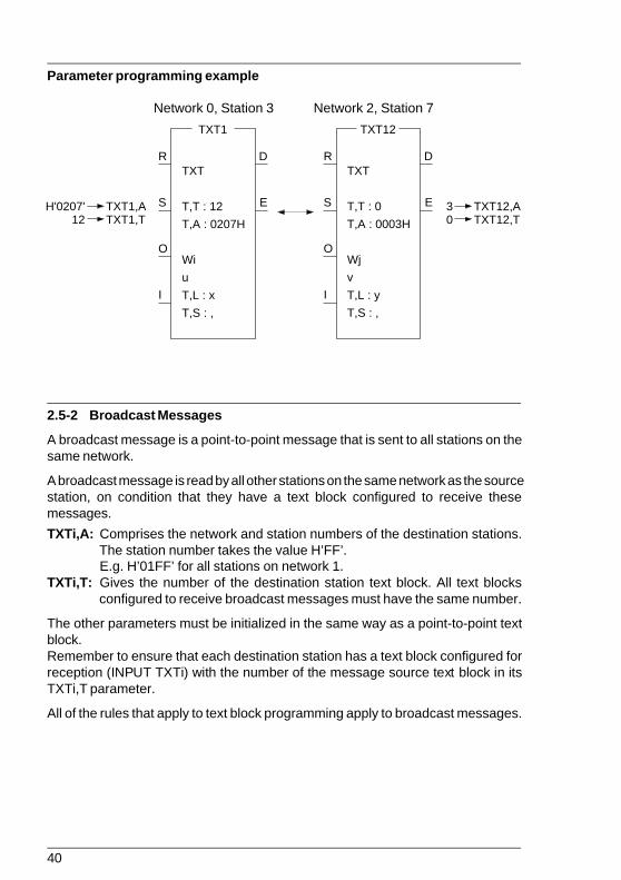
Parameter programming example
Network 0, Station 3 Network 2, Station 7
2.5-2 Broadcast Messages
A broadcast message is a point-to-point message that is sent to all stations on thesame network.
A broadcast message is read by all other stations on the same network as the sourcestation, on condition that they have a text block configured to receive thesemessages.
TXTi,A: Comprises the network and station numbers of the destination stations.The station number takes the value H’FF’.E.g. H’01FF’ for all stations on network 1.
TXTi,T: Gives the number of the destination station text block. All text blocksconfigured to receive broadcast messages must have the same number.
The other parameters must be initialized in the same way as a point-to-point textblock.Remember to ensure that each destination station has a text block configured forreception (INPUT TXTi) with the number of the message source text block in itsTXTi,T parameter.
All of the rules that apply to text block programming apply to broadcast messages.
TXT1
R
S
O
I
D
E
TXT
T,T : 12
T,A : 0207H
Wi
u
T,L : x
T,S : ,
H'0207'12
TXT1,ATXT1,T
30
TXT12,ATXT12,T
TXT12
R
S
O
I
D
E
TXT
T,T : 0
T,A : 0003H
Wj
v
T,L : y
T,S : ,
Page 40 - Recouvrement Noir
41
Software Installation 2
Station 6 Station H' OC'
Network 1
TXT Network 2
TSX 87-40 TSX 47-40
TSX 87-40
Station 4
TXT
TXT5
TXT8
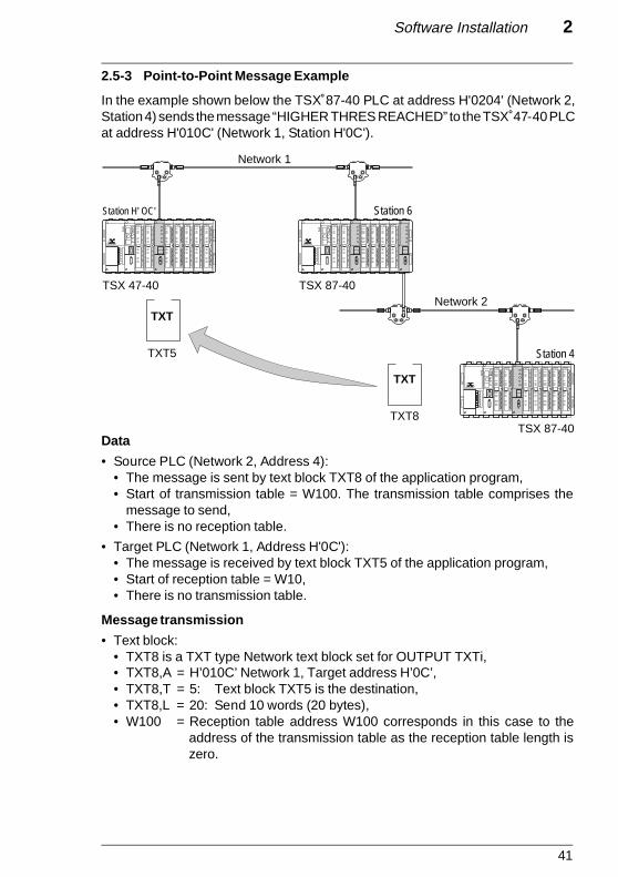
2.5-3 Point-to-Point Message Example
In the example shown below the TSX 87-40 PLC at address H'0204' (Network 2,Station 4) sends the message “HIGHER THRES REACHED” to the TSX 47-40 PLCat address H'010C' (Network 1, Station H'0C').
Data
• Source PLC (Network 2, Address 4):• The message is sent by text block TXT8 of the application program,• Start of transmission table = W100. The transmission table comprises the
message to send,• There is no reception table.
• Target PLC (Network 1, Address H'0C'):• The message is received by text block TXT5 of the application program,• Start of reception table = W10,• There is no transmission table.
Message transmission
• Text block:• TXT8 is a TXT type Network text block set for OUTPUT TXTi,• TXT8,A = H’010C’ Network 1, Target address H’0C’,• TXT8,T = 5: Text block TXT5 is the destination,• TXT8,L = 20: Send 10 words (20 bytes),• W100 = Reception table address W100 corresponds in this case to the
address of the transmission table as the reception table length iszero.
Page 41 - Recouvrement Noir

42
W11
W10 49 (I) 48 (H)
47 (G)48 (H)
48 (H) 43 (C)
45 (E)44 (D)W19
W18
• Transmission table:
Message reception
• Text block:• TXT5 is a TXT type Network text block set for INPUT TXTi,• TXT5,A = H’0204' Network 2, Source station H’04',• TXT5,T = 8: Text block TXT8 is the source,• TXT5,L = 0: Transmission table length is zero,• W10 = Reception table address,• Reception table:
• TXT5,S = 20: Receive 20 bytes (10 words).
W103
W102
W101
W100 49 (I) 48 (H)
47 (G)48 (H)
52 (R) 45 (E)
20 (Space)54 (T)
52 (R) 48 (H)
45 (E)53 (S)
52 (R) 20 (Space)
45 (E)41 (A)
48 (H) 43 (C)
W106
W105
W104
W108
W107
W109 44 (D) 45 (E)
Page 42 - Recouvrement Noir

43
Software Installation 2
P
I
O
CYT
IT Task Read TLG
IT Task Fast or Mast Write TLG
IT
2.6 Priority Communication - Telegram
2.6-1 General
Note: The telegram service is only supported by TSX Series 7 Model 40 PLCs.
A telegram is a specific type of text block used for priority transmission of shortmessages (up to 16 bytes max.) between two stations. It can be used by any taskin the sender PLC (Master task, fast task or interrupt task) and can be sent to anystation on the same network.
When a telegram is sent, the PLC processor immediately sends the message to thenetwork interface module, without waiting for the end of the Master task cycle.
In reception, as soon as the message is received by the network interface module,an interrupt is generated and sent to the PLC processor. The destination applicationinterrupt task (IT task) then reads the telegram and performs any required actions.This process usually ensures application program-to-application program commu-nication in less than 30ms.
A telegram is sent by a TLG type Network function block. An application programcan only send one telegram in each cycle to each network interface. A PLC thatcomprises a number of network interfaces (e.g. in Bridge or data concentratorapplications) can simultaneously send a telegram from each network interface.
TLG text block parameters
The "TLG" text block function comprises the following parameters. They must bedefined on configuration:
• Text block number TXTi• Type of exchange TLG• Type of communication NET• Start of table address e.g.: W10• Reception table length 16 bytes max.• Transmission table length TXTi,L (16 bytes max.)• Type of addressing Direct or Indirect
Page 43 - Recouvrement Noir

44
F 8 7 0
Network Number 0 to H' 7F'
Station Number 0 to H' 3F'
The TLG text block also comprises:
• Input bits: Literal LadderStart "Transmission" OUTPUT TXTi S,O = 1Start "Reception" INPUT TXTi S,I = 1Start "Transmission-Reception" EXCHG TXTi S,I,O = 1Cancel exchange RESET TXTi R = 1
• Output bits:"Exchange complete" TXTi,D"Exchange error" TXTi,E
• Status word TXTi,S• Target address TXTi,A• Target text block number TXTi,T
TXTi,S
The status word (TXTi,S) comprises the number of bytes sent or received (1 to 16)by the text block by its transmission or reception table when the exchange is correct.If an exchange error occurs, (bit TXTi,E at 1), TXTi,S takes one of the values listedbelow:
1 : Exchange in progress cancelled by Reset,2 : Message longer than 16 bytes (in transmission), 3 : Power failure,4 : Module failure,6 : Telegram too long for the text block reception buffer,
10 : Incorrect text block parameters for indirect addressing,13 : Routing error (cannot access network),14 : System reconfiguring, module self-testing, etc.,15 : Telegram channel busy (in transmission).
This variable can only be read and is significant only when the exchange iscompleted.
TXTi,A
The destination address (TXTi,A) must be coded as:
Note: Parameters TXTi,L; TXTi,A and TXTi,T can be modified by program.
Page 44 - Recouvrement Noir

45
Software Installation 2
2.6-2 Telegram Programming
Transmission
The transmission of a telegram (TLG) type text block is programmed in the sameway as a TXT type text block.
Transmission is started when input "O" is set to 1 in Ladder language or with theOUTPUT TXTi instruction in Literal. The TLG text block can be started from theapplication program interrupt task, fast task or master task.
If transmission is unsuccessful, e.g. the destination PLC is powered-down, no TLGtext block is configured in Input, the telegram that was sent is returned to the senderMapway interface. This interface will then generated an interrupt. If an IT task isrunning and enabled (DMASKINT), it is executed. The IT task must be acknowledged(ACKINT) or the PLC will generate a MEM error condition and stop the application.
The use of TXTi,E and TXTi,D bits is described in sub-section 3.3, Data-RateControl.
Reception
A telegram is received by a TLG type text block.
The telegram destination network interface must know which text block is ready toreceive the message. To ensure this, the text block must be set-up as INPUT TXTi.
On reception of a telegram from the network, the network interface gives it priority,reads it and generates an interrupt that is sent to the PLC processor. The interruptstarts the application program interrupt task that must:• Determine which network interface generated the interrupt,• Read the telegram with the "READTLG" instruction.
The network interface that generated the interrupt is determined by the instruction:
READINT (Ixy;Bi)
x = Rack number (0),y = Module position in the rack (0 to 7),Bi= Copies the interrupt from the module to an internal bit. This bit goes to 1 whenan interrupt is detected.
Page 45 - Recouvrement Noir
46
The telegram is read by the instruction:
READTLG (Ixy;Wi)
x = Rack number (0),y = Module position in the rack (0 to 7),Wi = Read confirm that takes one of the following values:
0 : Reception successful,4 : Message longer than 16 bytes (in reception),5 : Incorrect destination address,6 : Reception network interface error,7 : Communication system reconfiguring,8 : Telegram reception already in progress,9 : No telegram waiting,
10 : No TSX MAP 1074 module,11 : TSX MAP 1074 but not supported,12 : Telegram reception refused,13 : No TLG text block configured in Input,14 : Telegram received with an bad check character (BCC),15 : Telegram channel busy.
Execution of this instruction copies the message to the reception buffer of the TLGtext block, sets the text block "D" bit to 1 and updates word Wi. The telegram is thenavailable for reading and all related actions.
Transmission - Reception
A TLG text block can be programmed for transmission/reception by the EXCHGTXTi instruction (or by setting bits S, I, O to 1). Responding to the text block is upto the application program of the destination PLC. This response must be sent bya TLG text block program for OUTPUT. Data reception is performed as describedabove (interrupt detection and telegram reading). The data received is stored in thereception table of the text block.
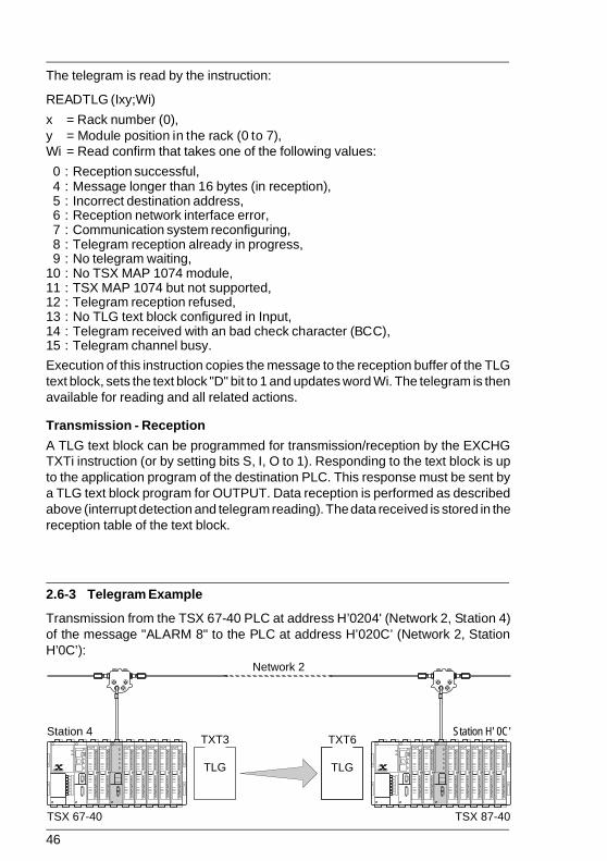
2.6-3 Telegram Example
Transmission from the TSX 67-40 PLC at address H’0204' (Network 2, Station 4)of the message "ALARM 8" to the PLC at address H’020C’ (Network 2, StationH’0C’):
TXT6 TXT3 Station 4 Station H' 0C'
TSX 87-40 TSX 67-40
Network 2
TLG TLG
Page 46 - Recouvrement Noir

47
Software Installation 2
W101
W100 4C (L) 41 (A)
41 (A) 52 (R)
20 (space) 4D (M)
38 (8) 20 (space) W103
W102
Data
• Source PLC (Station 4):
• The telegram is sent by application program text block TXT3,• Start of transmission table = W100. The transmission table comprises the
message to send,• There is no reception table.
• Target PLC (station H’0C’):
• The message is received by application program text block TXT6,• Start of reception table = W50,• Reception table length: 16 bytes,• There is no transmission table.
Message transmission
• Text block:
• TXT3 is a TLG type Network text block programmed for OUTPUT,• TXT3,A = H’020C’ destination address (Network 2, Station H’0C’),• TXT3,T = 6 : TXT6 is the destination text block,• TXT3,L = 8 : Send 8 bytes,• W100 = Reception table address. As there is no reception table (nul length),
W100 corresponds to the transmission table address.
• Transmission table.
• Telegram transmission
The telegram is sent from the master task:
< Transfer data to the transmission table! W152[4] → W100[4]
< Send telegram! OUTPUT TXT3
Page 47 - Recouvrement Noir

48
Message reception
• Text block:
• TXT6 is TLG type Network text block programmed in INPUT,• TXT6,A = H’0204' source address (Network 2, Station 4),• TXT6,T = 3: Text block 3 is the source,• Recept. length = 16: receive 16 bytes max.,• W50 = Reception table address,• There is no transmission table, TXT6,L = 0.
The telegram destination module is located in Rack 0, Slot 2. The message isreceived in two steps:
• Master task:
< Activate IT task! Start CTRL 1
< Validate interrupts! DMASKINT (I 02)
< Set text block TXT6 to receive! INPUT TXT6
• Interrupt task:
< Read the module interrupt! READINT (I02;B14)
< If interrupt bit (B14) is present, read the telegram! IF B14 THEN JUMP L10
< Continue program! ......
< Read telegram! L10: READTLG (I02;W45); RESET B14
< Analyze correct read confirm! IF [W45 = 0] then jump L20
< Process errors (analyze W45)! [IF W45 = ...] THEN ................................
....................................................................
< Number of bytes received and stored in word W30! L20: TXT6,S → W30
< Process data received! W50[W2]...................................................................
Page 48 - Recouvrement Noir
49
Software Installation 2
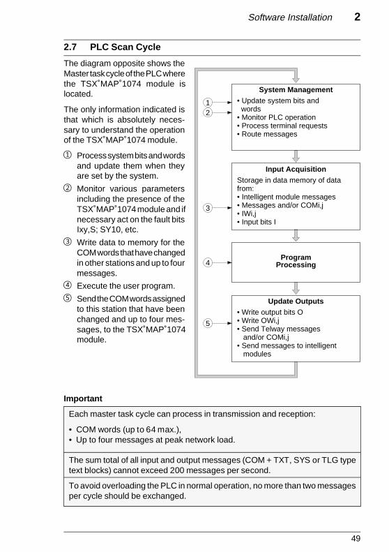
2.7 PLC Scan Cycle
The diagram opposite shows theMaster task cycle of the PLC wherethe TSX MAP 1074 module islocated.
The only information indicated isthat which is absolutely neces-sary to understand the operationof the TSX MAP 1074 module.
1 Process system bits and wordsand update them when theyare set by the system.
2 Monitor various parametersincluding the presence of theTSX MAP 1074 module and ifnecessary act on the fault bitsIxy,S; SY10, etc.
3 Write data to memory for theCOM words that have changedin other stations and up to fourmessages.
4 Execute the user program.
5 Send the COM words assignedto this station that have beenchanged and up to four mes-sages, to the TSX MAP 1074module.
Important
Each master task cycle can process in transmission and reception:
• COM words (up to 64 max.),• Up to four messages at peak network load.
The sum total of all input and output messages (COM + TXT, SYS or TLG typetext blocks) cannot exceed 200 messages per second.
To avoid overloading the PLC in normal operation, no more than two messagesper cycle should be exchanged.
• Update system bits and words • Monitor PLC operation • Process terminal requests • Route messages
Storage in data memory of data from: • Intelligent module messages • Messages and/or COMi,j • IWi,j • Input bits I
Program Processing
1 2
3
4
5
Input Acquisition
System Management
Update Outputs • Write output bits O • Write OWi,j • Send Telway messages and/or COMi,j • Send messages to intelligent modules
Page 49 - Recouvrement Noir

50
2.8 Multiple Network Configurations
2.8-1 Module Configuration
In a multiple network configuration (Mapway and/or Telway), there are threepossible cases:
• The network interface is in a station that is at the end of a network drop (stations1.a, 1.b, 1.c, 2.b, 2.c, 3.b),
• The network interface is in a station that comprises more than one networkinterface connected to different networks without being a network bridge (station1.e/3.a),
• The network interface is in a station that is a network bridge (station 1.d/2.a).
In the first two cases there is no need to configure the network interface modules.All of the routing information is held by the bridge station on the network to whichthey are connected.
In the last case (bridge PLC), the network interfaces must be configured.
A network bridge station is configured with PL7-NET software. PL7-NET is anX-TEL Software Workshop option.
Station 1.c
Station 1.b
Station 3.b
Station 2.b
Station 2.c
Station 1.a
Station 1.e/3.a
Station 1.d/2.a
Network 3 Network 2
Network 1
N1/N2 Bridge Station
Page 50 - Recouvrement Noir

51
Software Installation 2
Processing
Input Acquisition
Output Updating
Time available for asynchronous messages (module to module)
Cycle Time
The following operations must be performed:
• Description of the entire network layout and entry of the name and number (0 toH’7F) assigned to each network,
• Selection of the stations that form a network and assignment of station addresses(0 to H’3F’),
• Network interconnection by selection of bridge PLC stations,• Assignment in each bridge of modules to the different networks,• Storage of network layout information on disk. For each bridge, this file contains
a complete list of the networks it serves,• Transfer of this file to all of the bridge stations in the network layout.
For more information on the use of this program, refer to the PL7-NET User'sManual, TXT DM PL7 NET V4E.
2.8-2 PLC Cycle Time
The master task cycle time of a bridge PLC depends on the type of networksconnected (Mapway to Mapway or Mapway to Telway bridge).
Reminders on PLC scan cycles
Page 51 - Recouvrement Noir

52
Mapway to Mapway bridge PLC
Data routing is performed in the field reserved for the asynchronous messagesystem.
The time reserved for message system processing (message transfer betweensegments) corresponds to the cycle time less the application program processingtime.
To improve performance of a Mapway to Mapway bridge PLC, it must have thefollowing characteristics:• A long cycle time,• No sequential processing,• No COM word management.
Example: A bridge PLC with a 200 ms cycle time and no sequential processing willmake approx. 195 ms, or 97% of its cycle time available to messagesystem processing.
Mapway to Telway bridge PLC
Data routing is performed when outputs are updated (synchronous messagesystem) at the rate of one message per cycle.
The time reserved for updating outputs is defined by the PLC system and cannotbe modified by the user.
To improve performance of a Mapway to Telway bridge PLC, it must have thefollowing characteristics:• A short cycle time,• No sequential processing,• No COM word management.
Example: A bridge PLC with a 10 ms cycle time and no sequential processing willbe able to route a message every 10 ms.
Page 52 - Recouvrement Noir
53
Maintenance 3
Maintenance Section 3
Sub-section Page
3.1 Troubleshooting 54
3.1-1 General 543.1-2 LED Indicators 543.1-3 LED Displays 563.1-4 Troubleshooting Using the LED Indicators and Displays 57
3.2 Self-Tests and Specific Tests 59
3.2-1 Starting the Self-Tests 593.2-2 Starting the Specific Tests 60
3.3 Data-Rate Control 62
Page 53 - Recouvrement Noir

54
3.1 Troubleshooting
3.1-1 General
The front panel of TSX MAP 1074 modulescomprises five indicator LEDs and two sevensegment LED displays.
These indicators and displays are used todisplay important information on the operationof the module and its connection to the Mapwaynetwork.
3.1-2 LED Indicators
The “RUN” LED
This green LED indicates the general condition of the module. It is lit when themodule is operational and active. It is extinguished when the module is notoperational.
When the module connects to the network and while the self-tests are in progress,this LED blinks. It remains lit when the self-tests have been successfully completedand during normal module operation. If a fault is detected it is extinguished andinhibits the module from becoming active.
This LED is hardware controlled. It is extinguished by the watchdog, triggered by amodule failure.
The “DEF” LED
This red LED lights when a TSX MAP 1074 module fault occurs.
This LED lights briefly when the module is powered-up, it is extinguished when theself-test phase starts. It will only light again if:
• One of the tests performed during the self-test phase detects an error. The errorcode will be displayed by the seven segment LED displays (refer to sub-section3.2-1),
• A permanent error is detected during normal operation,• The TSX MAP ACC1 terminal block is disconnected from the module.
INR
RX
TX
RUN
DEF
MAP 107
Page 54 - Recouvrement Noir

55
Maintenance 3
This LED is software controlled. When the internal software that controls themodule, detects an operating fault that affects proper module operation, it lights the“DEF” LED. This LED does not automatically light when the “RUN” LED isextinguished.
The “INR” (IN Ring) LED
This yellow LED lights to indicate that the TSX MAP 1074 module is connectedto the Mapway network and that it is active in passing the token on the bus.
It lights briefly when the module is powered-up and is extinguished when the self-test phase starts.The last self-test checks the network, if at least one other station is connected. Onceit has done this, it sends an “add station” request so that the newly powered-upmodule can obtain the token. If it is successful in adding the module to the network,the “INR” LED lights.
If for any reason, the module cannot connect to the network and gain access to thetoken, the “INR” LED will be extinguished.
This LED is software controlled. As long as it is extinguished, the station cannotsend messages, it can only receive them.
Note: If the network number of a station is different than that of the other stations, its “INR”LED will remain lit (token passing is detected) but it will never be able to send on thenetwork as the token is not addressed to it.
The “RX” and “TX” LEDs
These two yellow LEDs indicate that the TSX MAP 1074 module has detecteddata reception (RX) or transmission (TX) activity. These LEDs do not indicatetoken passing or control frames, only data transmission and reception to andfrom the individual station.
On initialization, these two LEDs light briefly, only to be extinguished by the start ofthe self-test procedure. They are software controlled.
Page 55 - Recouvrement Noir

56
3.1-3 LED Displays
The TSX MAP 1074 module comprises two seven segment plus decimal point LEDdisplays.
When the module is powered-up a random value will be displayed and immediatelycleared.
During the self-test phase, the displays show the number of the test in progress. Ifa fault is detected, the corresponding error code is displayed by the LEDs and the“DEF” LED is lit.
Once the self-tests have been completed successfully, the LEDs alternately displaythe network and station number of the module. The number of the network that themodule is connected to is displayed first, with a decimal point in the lower right ofthe display. The station number assigned to the module is also displayed, withoutthe decimal point.
In normal operation, the LEDs display the network address of the station asnetwork number followed by the station number.
The station address display alternates cyclically over a period of approx. twoseconds. This sequence allows network diagnostics in Local mode. A check can beperformed to ensure that the network and station numbers are set correctly in theTSX MAP ACC1 terminal block.
As soon as a fault is detected during normal module operation, the “DEF” LED lightsand the LEDs display the appropriate error code.
Page 56 - Recouvrement Noir

57
Maintenance 3
3.1-4 Troubleshooting Using the LED Indicators and Displays
The combined use of the indicator and display LEDs will identify a number ofoperating faults and their causes.
The table below lists the main faults that can be detected and the remedial actionthat should be taken.Before taking any action, the module should first be disconnected, reconnected andreinitialized to ensure that the fault persists.
Indicators Probable Causes Remedial Action
• LED failure • Check supply to the station
• Power supply failure • Change the power supply module
• Self-test fault (*) • Refer to the error code displayed
• Permanent fault (*)
• Terminal block absent (**) • Fit the terminal block
• Fault identified by an error • Refer to the error code displayedcode displayed
• Terminal block address error • Check the coding in the terminal codeblock
• Station excluded from the • Check network statuslogical ring
• Network failure
• PLC not connected • Check the PLC
• Normal display during normal module operation
(*) Error code displayed; (**) “Eb” displayed
Note: The “TX” and “RX” LEDs are not shown in the above table as they are not used fortroubleshooting the module.
INR
RUN
DEF
INR
RUN
DEF
INR
RUN
DEF
INR
RUN
DEF
INR
RUN
DEF
INR
RUN
DEF
Page 57 - Recouvrement Noir

58
List of error codes (other than self-test error codes)
If a fault is detected during normal operation or when a specific test is run (refer tosub-section 3.2), one of the values shown in the list below will be displayed.
Error code Fault Remedial Action
20 LCC initialization error Reset the PLC (SY0 = 1).(resource allocation, self-tests).
21 Problem detected in normal operation Reset the PLC (SY0 = 1).(e.g. invalid data).
22 Address duplicated on the same Change the station code set innetwork. the terminal block.
23 Modem problem Check that the module is correctlyinstalled and its mounting screwstight.Reset the PLC (SY0 = 1) or coldrestart.
31 Initialization problem during Change the module.initialization phase.
41 Initialization problem in the COM Change the module.protocol.
42 COM word reconfiguration problem Change the module.
51 Initialization problem in the Change the module.TSX Series 7 protocol.
Eb Terminal block absent. Fit the terminal block.
Page 58 - Recouvrement Noir

59
Maintenance 3
3.2 Self-Tests and Specific Tests
3.2-1 Starting the Self-Tests
Each time it is powered-up, the TSX MAP 1074 module runs a self-test sequencethat comprises:
• Module micro-program checksum,• Checking the RAM memory assigned to the microprocessor,• Checking the logic of the shared memory used to exchange data with the PLC,• Inserting the station into the network logical ring and token passing. Sending test
frames to the previous and next stations on the network.
The self-tests are triggered after the coded value (network and station numbers) isacquired by the TSX MAP ACC1 terminal block.
While the self-tests are in progress, the numbers of the individual tests in progressare displayed on the seven segment LED displays.
If the self-tests are completed successfully, the module becomes active and the“RUN” and “INR” LEDs are lit.
Any fault that is detected is indicated by the “DEF” LED. The fault code is displayedon the seven segment LED indicators.
List of self-testsThere are eight classes of self-tests shown as “X_.” on the LED displays (X takesa value from 1 to 8).
Normally, the number of each class of test will be displayed as the tests areperformed. If a fault is detected, the complete two figure error code will be displayed.
The table below shows the complete list of errors with the values displayed duringa normal test sequence.
Value displayed Self-tests
1_. Minimal self-test.
2_. PLC bus interface (SMU) test.
3_. PLC bus shared RAM test.
4_. System ROM checksum test.
5_. I/O Test.
6_. Token Bus Controller (TBC) test.
7_. Interrupt test.
8_. Network test.
Page 59 - Recouvrement Noir

60
3.2-2 Starting the Specific Tests
The TSX MAP 1074 module comprises a system that supports the running ofspecific tests for maintenance purposes. The tests can be selected from the fourthumbwheel switches in the TSX MAP ACC1 terminal block.
On power-up, the value coded in the terminal block is read. If the value correspondsto a network and station number, the module runs the self-test sequence and if it issuccessful, starts normal operation. If the value corresponds to a specific self-test,as listed overleaf, the module will run the corresponding test.
If the specific test runs correctly, the module loops back to the start of the test andruns it again. If the test is stopped before completion, the “DEF” LED will light andthe LED displays will display a test number. The tests are listed overleaf.
Specific test coding
The tests are run after the “STAT” thumbwheelswitches have been set to a value listedoverleaf. The “NET” thumbwheel switches mustbe set to H’FF’.
XX
FF
net
st
Net
wor
kS
tatio
n
Page 60 - Recouvrement Noir

61
Maintenance 3
“STAT” Setting Test Selected
FF Continuous self-tests
FE 80186 register test
FD 512 KB RAM test
FC Reserved
FB PLC bus register test
FA 32 KB PLC bus interface RAM test
F9 256 KB checksum ROM test
F8 ROM type test
F7 Indicator LED test
F6 7 segment LED display test
F5 Status test
F4 Timer interrupt test
F3 Direct memory access interrupt test
F2 PLC bus interrupt test
F1 Reserved
F0 Token Bus Controller interrupt test
EF Token Bus Controller reset init test
EE CPU Token Bus Controller interface test
ED Token Bus Controller loopback mode test
EC - E1 Reserved
E0 Permanent network test
DF - 80 Reserved
7F - 40 Reserved
3F - 00 Station Number
Error codes
If a fault is detected by a specific test, an error code is displayed by the module. Thelist of error codes is the same as that given in sub-section 3.2-1.
Page 61 - Recouvrement Noir

62
3.3 Data-Rate Control
Sending a text block changes the state of bits TXTi,D and TXTi,E. The possiblevalues that these bits can take are:
Bit TXTi,D Bit TXTi,E Description
0 0 Exchange in progress
1 0 Exchange ended without error or no exchange
1 1 Exchange ended on error
0 1 Exchange not ended, exchange initially started onerror
Power break or target disconnection
When a text block wired for EXCHG (or with inputs S, I and O at 1) sends a request,it is set to await a response and waits until it receives one. If a power failure occurs,or if the target station is disconnected, the source text block remains inhibited.
There are two possible cases:
Power break or target station disconnected during the exchange
Bits TXTi,D and TXTi,E remain at 0,
The application program of the source must take this case into account by includinga “time-out” in the use of the source text block.If no response is received before the time-out, then the text block should be resetto zero (Reset TXTi).
Power supply fault or disconnection of the target station before theexchange is started
The text block is set to error, bits TXTi,D and TXTi,E are set to 1 and the status wordTXTi,S takes the value 3.
Page 62 - Recouvrement Noir

63
Technical Specifications 4
Technical Specifications Section 4
Sub-section Page
4.1 Performance 64
4.1-1 Application-to-Application Transfer Time 644.1-2 Telegram Transfer Time 664.1-3 Request Transaction Time 684.1-4 Uploading Application Programs 704.1-5 Mapway-Mapway Bridge Processing Time 724.1-6 Mapway-Telway Bridge Processing Time 72
Page 63 - Recouvrement Noir

64
4.1 Performance
4.1-1 Application-to-Application Transfer Time
AAT: is the Application-to-Application Transfer time. This is the elapsed time fromthe moment a message is sent by the source station (START TXTi) till the momentit is received by the destination station (DONE bit processed by the applicationprogram).
Example
TC1 Source PLC cycle time,
TC2 Destination PLC cycle time,
CPL S Source PLC TSX MAP 107 module transmission processing time,
MPW Mapway network transit time,
CPL D Destination PLC TSX MAP 107 module transmission processing time.
DONE is accepted
TXT TXT
Start TXTi TXTj,D = 1
CPL S
TC1
"Start TXTi"
AAT
TC1
MPW
CPL D
TC2 TC2
Page 64 - Recouvrement Noir
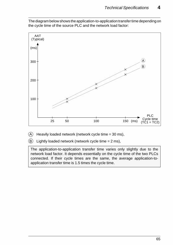
65
Technical Specifications 4
The diagram below shows the application-to-application transfer time depending onthe cycle time of the source PLC and the network load factor:
A Heavily loaded network (network cycle time = 30 ms),
B Lightly loaded network (network cycle time = 2 ms),
The application-to-application transfer time varies only slightly due to thenetwork load factor. It depends essentially on the cycle time of the two PLCsconnected. If their cycle times are the same, the average application-to-application transfer time is 1.5 times the cycle time.
PLCCycle time
(TC1 = TC2)
100
AAT(Typical)
200
300
25 50 100 150 (ms)
A
B
(ms)
Page 65 - Recouvrement Noir

66
Process "DONE" bit
TXT TXT
Output TXTi TXTj,D = 1
CPL S
TC1
"Output TXTi"
TTT
TC1
MPW
CPL D
TC2 TC2
IT
4.1-2 Telegram Transfer Time
TTT: The Telegram Transfer Time is the time that elapses between telegramtransmission by the source station (OUTPUT TXTi) and telegram reception by theinterrupt task of the destination station (DONE bit accepted by the applicationprogram).
Example
TC1 Source PLC cycle time,
TC2 Destination PLC cycle time,
CPL S Source PLC TSX MAP 1074 module transmission processing time,
MPW Mapway network transit time,
CPL D Destination TSX MAP 1074 module transmission processing time,
IT Interrupt task processing time.
Page 66 - Recouvrement Noir

67
Technical Specifications 4
Network cycle time
10
20
30
TTT (Typical)
2
(ms)
10 20 30 (ms)
The diagram below shows telegram transfer time depending on network cycle time:
Page 67 - Recouvrement Noir

68
4.1-3 Request Transaction Time
RTT: The Uni-TE Request Transaction Time is the time that elapses betweentransmission of a request and processing, by the source, of the confirm that is sentback.
Example
TC1 Source PLC cycle time,
TC2 Destination PLC cycle time,
CPL S Source PLC TSX MAP 1074 module transmission processing time,
MPW Mapway network transit time,
CPL D Destination PLC TSX MAP 1074 module transmission processing time.
TXT SystemStart TXTiConfirm
ConfirmprocessingCPL S
TC1
"Start TXTi"
RTT
TC1
MPW
CPL D
TC2 TC2
CPL D
MPW
CPL S
TC1 TC1
Page 68 - Recouvrement Noir
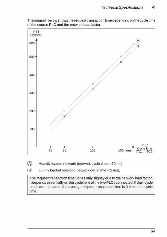
69
Technical Specifications 4
The diagram below shows the request transaction time depending on the cycle timeof the source PLC and the network load factor:
A Heavily loaded network (network cycle time = 30 ms),
B Lightly loaded network (network cycle time = 2 ms),
The request transaction time varies only slightly due to the network load factor.It depends essentially on the cycle time of the two PLCs connected. If their cycletimes are the same, the average request transaction time is 3 times the cycletime.
PLCCycle time
(TC1 = TC2)
100
200
300
25 50 100 150 (ms)
B
RTT(Typical)
400
500
(ms)A
Page 69 - Recouvrement Noir

70
CPL S
PLT
MPW
CPL D
Upload
Confirm
PLC
CPL D
MPW
CPL S
IBM PC
4.1-4 Uploading Application Programs
PLT: Program Load Time is the time required to upload (or download) an applicationprogram via Mapway (upload and receive confirm). It depends on the size of theprogram to be transferred. The transfer time will therefore be almost entirelyunaffected by the network load factor.
ExampleOnce logical connection is established, the cycle shown below applies to eachprogram segment of 128 bytes.
CPL S Source PLC TSX MAP 1074 module transmission processing time,
MPW Mapway network transit time,
CPL D Destination PLC TSX MAP 1074 module transmission processing time,
PLC The transfer time to the PLC of the destination station, with PLC stopped.
Note: If the FTX 507 is connected to the terminal port of a PLC, the following times mustbe added to the times shown above:• Transfer time between workstation and PLC (typically one second per K byte),• The PLC processing time (typically 2.5 times the cycle time).
Page 70 - Recouvrement Noir

71
Technical Specifications 4
Program size
(K bytes)
10
20
30
100
PLT (Typical)
40
50
60
10 50
(sec)
The diagram below shows the time required to upload an application program overa heavily loaded Mapway network (network cycle time = 20 ms) depending on thesize of the program:
The application program upload (or download) transfer time is increasedconsiderably when the terminal is not directly connected via an interface to theMapway network.
This time only varies slightly depending on the network load.
Page 71 - Recouvrement Noir

72
TSX MAP 1074
PLC
TSX MPT 10
Network 1
Network 2
TSX MAP 1074
PLC
TSX MAP 1074
Network 1
Network 2
4.1-5 Mapway-Mapway Bridge Transit Time
MMB: Is the time taken by a message to movefrom one network to another. It depends on theTSX MAP 1074 module processing time andon the time required by the bridge PLC proces-sor to route the message.
The Mapway-Mapway bridge transit time is approx. 20 ms for 128 characters.
4.1-6 Mapway-Mapway Bridge Transit Time
MTB: Is the time taken by a message to movefrom a Mapway network to a Telway network orvice versa. It depends on the TSX MAP 1074module processing time and on the time re-quired by the bridge PLC processor to routethe message.
The Mapway-Telway bridge transit time is usually 1,5 times the PLC cycle timefor each message.
Page 72 - Recouvrement Noir

73
Appendix 5
Sub-section Page
5.1 Module Design 74
5.1-1 Software Design 745.1-2 Hardware Design 77
5.2 TSX Series 7 V3 PLC Special Points 78
5.3 Uni-TE Read Requests 80
5.3-1 Read a Bit 805.3-2 Read a Word 815.3-3 Read Objects 825.3-4 Read a System Bit 845.3-5 Read the Memory Image of an I/O Bit 855.3-6 Read a Constant Word 875.3-7 Read a System Word 885.3-8 Read a COM Word 895.3-9 Read a Timer 905.3-10 Read a Monostable 915.3-11 Read a Counter 925.3-12 Read a Register 935.3-13 Read Grafcet Steps 945.3-14 Read a Double Word 955.3-15 Read a Constant Double Word 965.3-16 Read a Grafcet Step 97
5.4 Uni-TE Write Requests 98
5.4-1 Write a Bit 985.4-2 Write a Word 995.4-3 Write Objects 1005.4-4 Write a System Bit 1025.4-5 Write the Memory Image of an I/O Bit 1035.4-6 Write a System Word 1045.4-7 Write a COM Word 1055.4-8 Write a Timer Preset 1065.4-9 Write a Monostable Preset 1075.4-10 Write a Counter Preset 1085.4-11 Write a Register Input Word 1095.4-12 Write a Double Word 1105.4-13 Run 1115.4-14 Stop 112
Appendix Section 5

74
5.1 Module Design
5.1-1 Software Design
The diagram below shows the software design layout and the various functions ofa Mapway network module.
Definition of the Main Functions
Virtual Time Operating System (VTOS)
This is the real-time core that is used for:
• Executing the tasks in a multi-task environment,• Communication between tasks using mailboxes and ports,• Allocating and releasing the memory and the interrupts.
BUS Driver
This function ensures the control of communication between the PLC and thedevice. When a Telemecanique PLC is used, this function is designed as a driverfor the PLC bus interface (SMU) and a SMU access interface that can be accessedby application services. This function controls three simultaneous communicationchannels: A synchronous COM channel, a synchronous and an asynchronousmessage channel (synchronization is ensured by the PLC cycle).
VTOS
SMU Driver
TSXSeries 7
Uni-TE
COM
InitTests
VTOSLoader
Bridge
SMAP
NMA
LLC Class 3 Interface
TBC Driver
75
Appendix 5
COM
This function controls the service that exchanges COM words over the network. Itensures the periodical transmission of a list of words initiated by the PLC processor.It provides a copy of the entire COM word field on each PLC cycle. An important partof this function is delegated to the SMU driver: control of a COM word communica-tion memory channel between the network module and the PLC processor. TheCOM word function also interfaces with the LLC service (described below).
TSX Series 7
This is the specific Telemecanique network service. This function sends TSX Series 7datagrams (text blocks, Uni-TE requests, program, adjust and debug requests, etc.)to the destination station on the network. It also receives datagrams from thenetwork and transmits them to the PLC processor via the SMU driver. In addition,this function receives configuration or control requests that are redirected to theSMAP function that handles them (described below).
The TSX Series 7 service comprises a specific LOC-DIAG function that provides anoverview of network control via the Uni-TE service and application protocol. Onlysome data objects are accessible by the LOC-DIAG service. This service convertssome Uni-TE requests from the SMU into SMAP requests or responds instantly toother requests. In the other direction, SMAP responses are converted back usingthe Uni-TE protocol and sent back to the SMU.
System Management Access Protocol (SMAP)
This function controls all of the network functions that are distributed to the module.SMAP also communicates with a network control server called Network Manage-ment Agent (NMA). In order to respond to requests from the NMA, SMAP interfacesdirectly with each function in the module.
Logical Link Control (LLC)
This function implements the interface with the IEEE 802.2 Class 3 LLC and theIEEE 802.4 MAC sub-layer driver.
Init and Tests
This function performs two functions:
• Starting VTOS and any other Mapway program in order to end the self-tests,• Synchronizing the changeover of the program from idle to running once the self-
tests have been completed successfully. It is also used to share commonresources such as structures and common addresses.
This service also controls the LED indicators and the seven segment LED displayson the front panel of the TSX MAP 1074 module.

76
VTOS Loader
This module function is used to load a process into the RAM of the network interface.This process can be performed in addition to, or in place of an existing interfaceprocess.The VTOS Loader process normally interfaces directly with the SMU. In MAPnetwork interfaces, an additional interface is built-in and this is accessed by the LLCfor loading by the network.
Note: Mapway network interfaces are designed for future software extensions, and inparticular MAP 3.0.

77
Appendix 5
5.2-2 Hardware Design
The design of the TSX MAP 1074 module is shown in the diagram below:
5 V Power consumption: 1.3 A Typical1.6 A Maximum
PLCBus
20 MHz.Clock 80186
CMOSM-Proc.
256 K x 4DRAM
128 K x 8EPROM
I/O
TBC(68824)
Modem
M-Proc.TBCI/F
Local M-Proc. bus
DRAM
EPROM
Displays
LEDs
Addresses
0 Type F connector
Standard 802.4/G interface
I/FBus
(SMU)
32 K Backed-up RAM
Transformer

78
5.2 TSX Series 7 V3 PLC Special Points
TSX Series 7 V3 PLCs (TSX 47-31, TSX 67-21 and TSX 87-31) have certain slightfunctional differences compared to TSX Series 7 Model 40 PLCs. A brief summaryof these differences is given below.
Number of modules
• Only one Mapway or Telway module is allowed in each rack.TSX Series 7 V3 PLC cannot therefore be used as bridge stations betweennetworks but can be connected to a multiple network layout.
COM word service
• The COM word service (in transmission and reception) is restricted to stationswith addresses from H’00' to H’0F’.
• COM size is restricted to four words per station. (A TSX Series 7 V3 stationtherefore imposes a four COM word size on all stations connected to the samenetwork as itself).
• The update and transfer of all COM words is performed at the end of each mastertask cycle.
• When a module is configured, its activity (in read and write) in relation to COMwords can be inhibited or enabled.
• Only system bits SY11 and SY12 are used (with the same functions as TSX Series 7Model 40 PLCs).
• System words SW65 to SW99 do not apply. Two new system words are usedhowever:
System word Function Description
SW0 Update COM Each bit in this word (0 to F) represents a stationwords on the network (0 to 15). A bit at 1 shows that the
corresponding station has sent its COM words.It is up to the user to reset this word tozero (by program).
SW2 Mapway station This word gives the decimal station numbernumber coded in the TSX MAP ACC1 Mapway module ter-
minal block.

79
Appendix 5
Uni-TE Service
• The Uni-TE service is identical to the one supported by TSX Series 7 Model 40PLCs.
• The circular byte shift left instruction:SLCWORD(Source;Length) is not supported. When the "read objects" request(H’36') is used, shifting of data received can only be performed by program.
Application-to-application communication
• This service is identical to the one supported by TSX Series 7 Model 40 PLCs.
Priority communication - Telegram
• TSX Series 7 V3 PLC do not support this service.
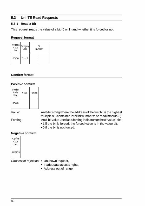
80
5.3 Uni-TE Read Requests
5.3-1 Read a Bit
This request reads the value of a bit (0 or 1) and whether it is forced or not.
Request format
Confirm format
Positive confirm
Value: An 8-bit string where the address of the first bit is the highestmultiple of 8 contained in the bit number to be read (modulo 8).
Forcing: An 8-bit value used as a forcing indicator for the 8 “value” bits:• 1 if the bit is forced, the forced value is in the value bit,• 0 if the bit is not forced.
Negative confirm
Causes for rejection: • Unknown request,• Inadequate access rights,• Address out of range.
00/00
RequestCodeHex.
CategoryCode
→0 7
BitNumber
30/48
ConfirmCodeHex.
Value Forcing
FD/253
ConfirmCodeHex.

81
Appendix 5
5.3-2 Read a Word
This request reads a word (W).
Request format
Confirm format
Positive confirm
Negative confirm
Causes for rejection: • Unknown request,• Inadequate access rights,• Address out of range.
04/04
RequestCodeHex.
CategoryCode
→0 7
WordNumber
34/52
ConfirmCodeHex.
Value
FD/253
ConfirmCodeHex.
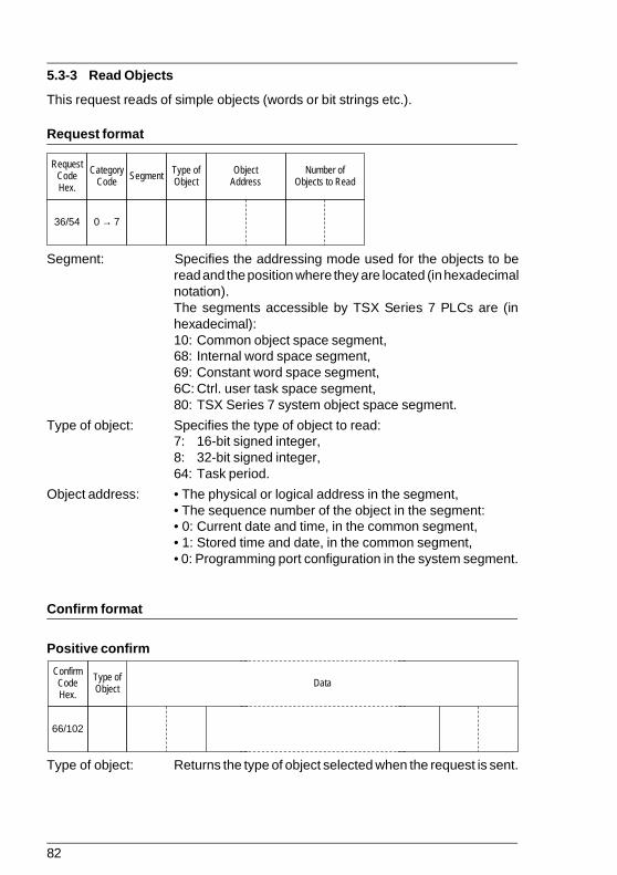
82
36/54
RequestCodeHex.
CategoryCode Segment Type of
ObjectObject
AddressNumber of
Objects to Read
→0 7
5.3-3 Read Objects
This request reads of simple objects (words or bit strings etc.).
Request format
Segment: Specifies the addressing mode used for the objects to beread and the position where they are located (in hexadecimalnotation).The segments accessible by TSX Series 7 PLCs are (inhexadecimal):10: Common object space segment,68: Internal word space segment,69: Constant word space segment,6C: Ctrl. user task space segment,80: TSX Series 7 system object space segment.
Type of object: Specifies the type of object to read:7: 16-bit signed integer,8: 32-bit signed integer,64: Task period.
Object address: • The physical or logical address in the segment,• The sequence number of the object in the segment:• 0: Current date and time, in the common segment,• 1: Stored time and date, in the common segment,• 0: Programming port configuration in the system segment.
Confirm format
Positive confirm
Type of object: Returns the type of object selected when the request is sent.
66/102
ConfirmCodeHex.
Type ofObject Data
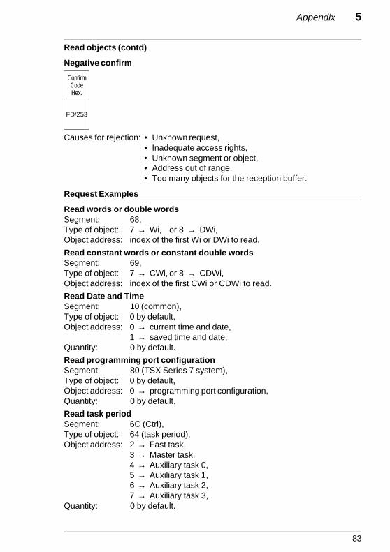
83
Appendix 5
Read objects (contd)
Negative confirm
Causes for rejection: • Unknown request,• Inadequate access rights,• Unknown segment or object,• Address out of range,• Too many objects for the reception buffer.
Request Examples
Read words or double wordsSegment: 68,Type of object: 7 → Wi, or 8 → DWi,Object address: index of the first Wi or DWi to read.
Read constant words or constant double wordsSegment: 69,Type of object: 7 → CWi, or 8 → CDWi,Object address: index of the first CWi or CDWi to read.
Read Date and TimeSegment: 10 (common),Type of object: 0 by default,Object address: 0 → current time and date,
1 → saved time and date,Quantity: 0 by default.
Read programming port configurationSegment: 80 (TSX Series 7 system),Type of object: 0 by default,Object address: 0 → programming port configuration,Quantity: 0 by default.
Read task periodSegment: 6C (Ctrl),Type of object: 64 (task period),Object address: 2 → Fast task,
3 → Master task,4 → Auxiliary task 0,5 → Auxiliary task 1,6 → Auxiliary task 2,7 → Auxiliary task 3,
Quantity: 0 by default.
FD/253
ConfirmCodeHex.

84
5.3-4 Read a System Bit
This request reads a system bit SY.
Request format
Confirm format
Positive confirm
Value: An 8-bit string, where the address of the first bit is the highestmultiple of 8 contained in the system bit number to be read(modulo 8).Only the bit corresponding to the bit to be found is significant.
Negative confirm
Causes for rejection: • Unknown request,• Inadequate access rights,• Bit number out of range.
01/01
RequestCodeHex.
CategoryCode
→0 7
SystemBit
Number
31/49
ConfirmCodeHex.
Value
FD/253
ConfirmCodeHex.

85
Appendix 5
5.3-5 Read the Memory Image of an I/O Bit
This request reads the memory image generated by an I/O module.
Request format
Module location: bit 0 → 2: Module number,bit 3 → 6: Rack number,bits 7 → 15: Reserved (0).
Confirm format
Positive confirm
Fault Code: Bit 7 = Fault: (0 = no, 1 = yes),Bits 6 to 4 = 0,Bits 0 to 3 = Type of fault:
0000: OK,0001: Terminal block or process fault,0010: Module absent,0011: Module failure,0100: Not an I/O module,0101: Incompatible with configuration,0110: Not configured,0111: Self-test error.
Configuration: bit 7: Configuration exists (0 = no, 1 = yes),bit 6: Defined type (0 = no, 1 = yes),bits 0 to 5: if type = 1 → catalog type number,
if type = 0 → default type number.
Value: The value of the module I/O bits. If an 8-bit module is used,the MSB contains null values that are not significant. “Value”is only significant if the fault bit = 0 (bit 7) and the configu-ration bit = 1 (bit 7).
02/02
RequestCodeHex.
CategoryCode
I/O ModuleLocation
→0 7
32/50
ConfirmCodeHex.
FaultCode
Config-uration Value Forcing
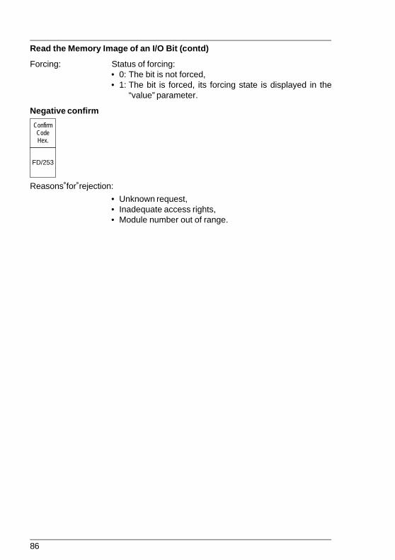
86
Read the Memory Image of an I/O Bit (contd)
Forcing: Status of forcing:• 0: The bit is not forced,• 1: The bit is forced, its forcing state is displayed in the
“value” parameter.
Negative confirm
Reasons for rejection:
• Unknown request,• Inadequate access rights,• Module number out of range.
FD/253
ConfirmCodeHex.
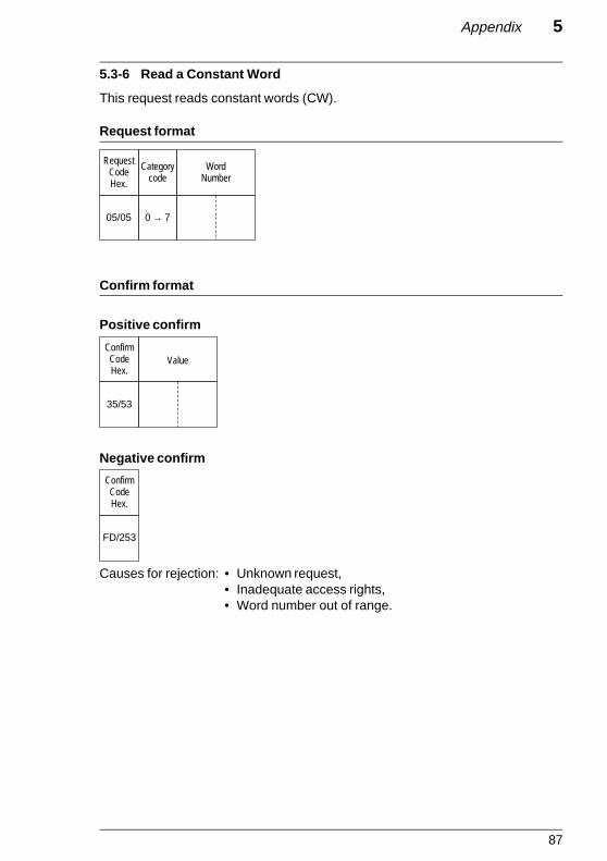
87
Appendix 5
5.3-6 Read a Constant Word
This request reads constant words (CW).
Request format
Confirm format
Positive confirm
Negative confirm
Causes for rejection: • Unknown request,• Inadequate access rights,• Word number out of range.
05/05
RequestCodeHex.
Categorycode
WordNumber
→0 7
35/53
ConfirmCodeHex.
Value
FD/253
ConfirmCodeHex.

88
5.3-7 Read a System Word
This request reads system words (CW).
Request format
Confirm format
Positive confirm
Negative confirm
Causes for rejection: • Unknown request,• Inadequate access rights,• Word number out of range.
06/06
RequestCodeHex.
CategoryCode
WordNumber
→0 7
36/54
ConfirmCodeHex.
Value
FD/253
ConfirmCodeHex.

89
Appendix 5
5.3-8 Read a COM Word
This request reads a COM (common) word.
Request format
Confirm format
Positive confirm
Station size: The number of COM words generated.
Negative confirm
Causes for rejection: • Unknown request,• Inadequate access rights,• Word number out of range,• RAM cannot be executed,• Station number out of range.
07/07
RequestCodeHex.
CategoryCode
StationNumber
→0 7
WordNumber
37/55
ConfirmCodeHex.
StationSize Value
FD/253
ConfirmCodeHex.

90
5.3-9 Read a Timer
This request reads all of the parameters of a timer.
Request format
Confirm format
Positive confirm
Time base: 0 → 10 ms1 → 100 ms2 → 1 sec.3 → 1 min.
Timer timed-out: 0 → no1 → yes
Timer running: 0 → no1 → yes
Type of preset: 0 → preset cannot be modified,1 → preset can be modified.
Negative confirm
Causes for rejection: • Unknown request,• Inadequate access rights,• Timer number out of range,• RAM cannot be executed.
09/09
RequestCodeHex.
CategoryCode
TimeNumber
→0 7
39/57
ConfirmCodeHex.
TimeBase
PresetValue
TimerTimed-out
Typeof
Preset
CurrentValue
TimerRunning
FD/253
ConfirmCodeHex.

91
Appendix 5
5.3-10 Read a Monostable
This request reads all of the parameters of a monostable.
Request format
Confirm format
Positive confirm
Time base: 0 → 10 ms1 → 100 ms2 → 1 sec.3 → 1 min.
Monostable running: 0 → no1 → yes
Type of preset: 0 → preset cannot be modified1 → preset can be modified
Negative confirm
Causes for rejection: • Unknown request,• Inadequate access rights,• Monostable number out of range,• RAM cannot be executed.
0A/10
RequestCodeHex.
CategoryCode
MonostableNumber
→0 7
3A/58
ConfirmCodeHex.
TimeBase
PresetValue
Mono-stable
Running
Typeof
Preset
CurrentValue
FD/253
ConfirmCodeHex.

92
5.3-11 Read a Counter
This request reads all of the parameters of a counter.
Request format
Confirm format
Positive confirm
Downcount overflow: 1 if the current counter value has gone from 0 to 9999,
Upcount overflow: 1 if the current counter value has gone from 9999 to 0,
Counter running: 0 → no,1 → yes,
Type of preset: 0 → preset cannot be modified,1 → preset can be modified.
Negative confirm
Causes for rejection: • Unknown request,• Inadequate access rights,• Counter number out of range,• RAM cannot be executed.
0B/11
RequestCodeHex.
CategoryCode
CounterNumber
→0 7
3B/59
ConfirmCodeHex.
PresetValue
Typeof
Preset
CurrentValue
Down-count
Overflow
UpcountOverflow
CounterRunning
FD/253
ConfirmCodeHex.

93
Appendix 5
5.3-12 Read a Register
This request reads all of the parameters of a register.
Request format
Confirm format
Positive confirm
Register type: 0 = FIFO register,1 = LIFO register,
Register empty: 0 → no,1 → yes,
Register full: 0 → no,1 → yes.
Negative confirm
Causes for rejection: • Unknown request,• Inadequate access rights,• Register number out of range,• RAM cannot be executed.
0E/14
RequestCodeHex.
CategoryCode
RegisterNumber
→0 7
3E/62
ConfirmCodeHex.
InputWord
OutputWord
RegisterType
RegisterEmpty
RegisterFull
RegisterLength
FD/253
ConfirmCodeHex.

94
5.3-13 Read Grafcet Steps
This request reads the Grafcet step activity bits (Xi).
Request format
Portion number: 0 = portion [X0•••••X127],1 = portion [X128•••••X255],2 = portion [X256•••••X383],3 = portion [X384•••••X511].
Confirm format
Positive confirm
Register type: A succession of 128 bits corresponding to the step numberin the selected portion:bit i = 0: step Xi inactive,bit i = 1: step Xi active.
Negative confirm
Causes for rejection: • Unknown request,• Inadequate access rights,• Portion number out of range,• No reservation.
2A/42
RequestCodeHex.
CategoryCode
PortionNumber
→0 7
5A/90
ConfirmCodeHex.
Data
FD/253
ConfirmCodeHex.

95
Appendix 5
5.3-14 Read a Double Word
This request reads a double word (DW).
Request format
Confirm format
Positive confirm
Negative confirm
Causes for rejection: • Unknown request,• Inadequate access rights,• Word number out of range,• Odd word number.
40/64
RequestCodeHex.
CategoryCode
Double WordNumber
→0 7
70/112
ConfirmCodeHex.
Double WordValue
FD/253
ConfirmCodeHex.

96
5.3-15 Read a Constant Double Word
This request reads a constant double word (CDW).
Request format
Confirm format
Positive confirm
Negative confirm
Causes for rejection: • Unknown request,• Inadequate access rights,• Word number out of range,• Odd word number.
41/65
RequestCodeHex.
CategoryCode
→0 7
Constant DoubleWord Value
71/113
ConfirmCodeHex.
Constant DoubleWord Value
FD/253
ConfirmCodeHex.

97
Appendix 5
5.3-16 Read a Grafcet Step
This request reads the state of a Grafcet step.
Request format
Type of step: 0: Grafcet step,1: Macro-step,2: Macro-step entry step,3: Macro-step exit step,4: Macro-step step.
Macro step nbr.: Comprises the number of the required macro-step or 0 if thestep type is 0.
Step nbr.: Comprises the number of the required step or 0 if the steptype is 1, 2 or 3.
Confirm format
Positive confirm
Active step: 0 → no,1 → yes,
Inhibited step: 0 → no,1 → yes.
Negative confirm
Causes for rejection: • Unknown request,• Inadequate access rights,• Step number out of range.
4B/75
RequestCodeHex.
CategoryCode
→0 7
Macro-Step
Number
Type ofNumber Reserved
00
StepNumber
7B/123
ConfirmCodeHex.
ActiveStep Not Used
00
Not Used
00 00
Inhibited
FD/253
ConfirmCodeHex.

98
5.4 Uni-TE Write Requests
5.4-1 Write a Bit
This request sets a bit to 1 or to 0.
Request format
Bit value: 0 → state 0,1 → state 1.
Confirm format
Positive confirm
Negative confirm
Causes for rejection: • Unknown request,• Inadequate access rights,• Bit number out of range.
10/16
RequestCodeHex.
CategoryCode
→0 7
BitValue
System BitNumber
FE/254
ConfirmCodeHex.
FD/253
ConfirmCodeHex.

99
Appendix 5
5.4-2 Write a Word
This request writes the content of a word.
Request format
Confirm format
Positive confirm
Negative confirm
Causes for rejection: • Unknown request,• Inadequate access rights,• Word number out of range.
14/20
RequestCodeHex.
CategoryCode
→0 7
WordNumber
WordValue
FE/254
ConfirmCodeHex.
FD/253
ConfirmCodeHex.

100
37/55
Request Code Hex.
Category code
→ 0 7
Segment Type of Object
Object Address
Number of Objects to Write Data
5.4-3 Write Objects
This request writes simple objects (words, word strings, etc.).
Request format
Segment: Specifies the addressing mode and the addressing field (inhexadecimal):10: Common object space segment,68: Internal word space segment,69: Constant word space segment,6C: Ctrl user task space segment,80: TSX Series 7 system object space segment.
Type of object: Specifies the object to write:7: 16-bit signed integer,8: 32-bit signed integer,64: Task period.
Object address: • The physical or logical address in the segment,• The sequence number of the object in the segment:• 0: Current date and time, in the common segment,• 1: Programming port configuration in the system segment.
Confirm format
Positive confirm
Negative confirm
FE/254
ConfirmCodeHex.
FD/253
ConfirmCodeHex.

101
Appendix 5
Write Objects (contd)
Negative confirm (contd)
Causes for rejection: • Unknown request,• Inadequate access rights,• Unknown object,• Address of the last object out of range.
Request Examples
Write words or double wordsSegment: 68,Type of object: 7 → Wi or 8 → DWi,Object address: Index of the first Wi or DWi to write,Quantity: Number,Data: Table of n objects,
Write constant words or constant double wordsSegment: 69,Type of object: 7 → CWi or 8 → CDWi,Object address: Index of the first CWi or CDWi to write,Quantity: Number,Data: Table of n objects,
Write Date and TimeSegment: 10 (common),Type of object: 0 by default,Object address: 0 → current time and date,Quantity: 0 by default,Data: 17 ASCII characters that contain the time and date information:
YYYYMMDDHHMMSS.TZ(T: tenths of a second, Z: trailer).
Write programming port configurationSegment: 80 (TSX Series 7 system),Type of object: 0 by default,Object address: 0 → programming port configuration,Quantity: 0 by default,Data: 1 byte that describes the new configuration.
Write task periodSegment: 6C (Ctrl),Type of object: 64 (task period),Object address: 2 → Fast task,
3 → Master task,4 → Auxiliary task 0,5 → Auxiliary task 1,6 → Auxiliary task 2,7 → Auxiliary task 3,
Quantity: 0 by default,Data: New task period within the time base allowed for each task.

102
5.4-4 Write a System Bit
This request writes a system bit SY...
Request format
Value: 0 or 1.
Confirm format
Positive confirm
Negative confirm
Causes for rejection: • Unknown request,• Inadequate access rights,• Bit number out of range.
11/17
RequestCodeHex.
CategoryCode
→0 7
System BitNumber Value
FE/254
ConfirmCodeHex.
FD/253
ConfirmCodeHex.

103
Appendix 5
5.4-5 Write the Memory Image of an I/O Bit
This request writes the memory image of an I/O module. As memory imageprocessing is used, no check is made to ensure that the module exists or is operatingcorrectly.
Request format
Module location: Bit 0 to 2: Module number,Bit 3 to 6: Rack number,Bits 7 to 15: Reserved (0).
I/O Bit number: 0 to 7: For an 8-bit module,0 to F: For a 16-bit module.
Value: 0 or 1.
Confirm format
Positive confirm
Negative confirm
Causes for rejection: • Unknown request,• Inadequate access rights,• I/O module number out of range,• I/O bit number out of range.
12/18
RequestCodeHex.
CategoryCode
→0 7
I/O ModuleLocation
I/OBit
NumberValue
FD/253
ConfirmCodeHex.
FE/254
ConfirmCodeHex.

104
5.4-6 Write a System Word
This request writes a system word (SW..).
Request format
Confirm format
Positive confirm
Negative confirm
Causes for rejection: • Unknown request,• Inadequate access rights,• System word number out of range.
15/21
RequestCodeHex.
CategoryCode
→0 7
ValueSystem WordNumber
FE/254
ConfirmCodeHex.
FD/253
ConfirmCodeHex.

105
Appendix 5
5.4-7 Write a COM Word
This request writes a COM (common) word.
Request format
Confirm format
Positive confirm
Negative confirm
Causes for rejection: • Unknown request,• Inadequate access rights,• Word number out of range,• RAM cannot be executed.
16/22
RequestCodeHex.
CategoryCode
→0 7
ValueStationNumber
COM WordNumber
FE/254
ConfirmCodeHex.
FD/253
ConfirmCodeHex.

106
5.4-8 Write a Timer Preset
This request writes the preset value of a timer (T) if it can be modified.
Request format
Preset value: Between 0 and 9999 (H’00' to H’270F’ inclusive).
Confirm format
Positive confirm
Negative confirm
Causes for rejection: • Unknown request,• Inadequate access rights,• Timer number out of range,• Preset cannot be modified,• Preset value out of range,• Cannot execute RAM.
17/23
RequestCodeHex.
CategoryCode
→0 7
TimerNumber
PresetValue
FD/253
ConfirmCodeHex.
FE/254
ConfirmCodeHex.

107
Appendix 5
5.4-9 Write a Monostable Preset
This request writes the preset value of a monostable (M), if it can be changed.
Request format
Preset Value: Between 0 and 9999 (H’00' to H’270F’) inclusive.
Confirm format
Positive confirm
Negative confirm
Causes for rejection: • Unknown request,• Inadequate access rights,• Monostable number out of range,• Preset cannot be changed,• Preset value out of range,• Cannot execute RAM.
18/24
RequestCodeHex.
CategoryCode
→0 7
MonostableNumber
PresetValue
FE/254
ConfirmCodeHex.
FD/253
ConfirmCodeHex.

108
5.4-10 Write a Counter Preset
This request writes the preset value of a counter (C).
Request format
Preset Value: Between 0 and 9999 (H’00' to H’270F’) inclusive.
Confirm format
Positive confirm
Negative confirm
Causes for rejection: • Unknown request,• Inadequate access rights,• Counter number out of range,• Preset cannot be modified,• Preset value out of range,• Cannot execute RAM.
19/25
RequestCodeHex.
CategoryCode
→0 7
CounterNumber
PresetValue
FE/254
ConfirmCodeHex.
FD/253
ConfirmCodeHex.

109
Appendix 5
5.4-11 Write a Register Input Word
This request writes a register input word (R).
Request format
Confirm format
Positive confirm
Negative confirm
Causes for rejection: • Unknown request,• Inadequate access rights,• Register number out of range.
1A/26
RequestCodeHex.
CategoryCode
→0 7
NumberRegister
Input WordValue
FE/254
ConfirmCodeHex.
FD/253
ConfirmCodeHex.
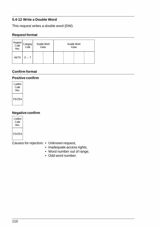
110
5.4-12 Write a Double Word
This request writes a double word (DW).
Request format
Confirm format
Positive confirm
Negative confirm
Causes for rejection: • Unknown request,• Inadequate access rights,• Word number out of range,• Odd word number.
46/70
RequestCodeHex.
CategoryCode
→0 7
Double WordValue
Double WordValue
FE/254
ConfirmCodeHex.
FD/253
ConfirmCodeHex.
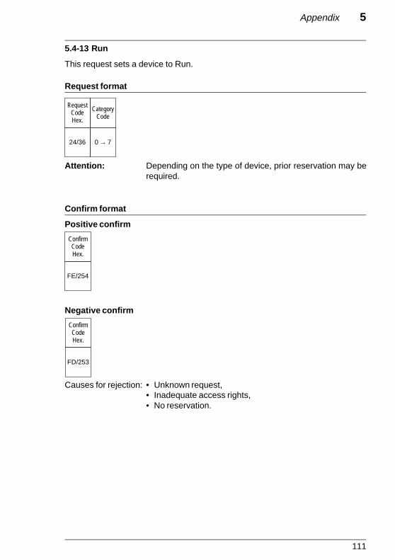
111
Appendix 5
5.4-13 Run
This request sets a device to Run.
Request format
Attention: Depending on the type of device, prior reservation may berequired.
Confirm format
Positive confirm
Negative confirm
Causes for rejection: • Unknown request,• Inadequate access rights,• No reservation.
24/36
RequestCodeHex.
CategoryCode
→0 7
FE/254
ConfirmCodeHex.
FD/253
ConfirmCodeHex.

112
5.4-14 Stop
This request stops a device.
Request format
Attention: Depending on the type of device, prior reservation may berequired.
Confirm format
Positive confirm
Negative confirm
Causes for rejection: • Unknown request,• Inadequate access rights,• No reservation.
25/37
RequestCodeHex.
CategoryCode
→0 7
FE/254
ConfirmCodeHex.
FD/253
ConfirmCodeHex.