general catalog hydraulic cylinders - smcdocumentatie.smc.ro/pdf/cilindri_hidraulici.pdf · compact...
TRANSCRIPT

HydraulicCylinders
General Catalog
Series CHKDBNominal pressure: 10MPa
Series CHMNominal pressure: 3.5MPa
Series CHANominal pressure: 3.5MPa
Series CH2E/CH2F/CH2G/CH2HNominal pressure: 3.5, 7, 14MPa
Series CHQBNominal pressure:3.5MPa
Series CHKGBNominal pressure: 16MPa
NewNew
Now boastingcushion seal &
the addition of ø32 bore size.
CAT.E111 B
NewNewHigh pressurecompact type

Compact Type Round TypeFeatures 1
16MPa20, 25, 32, 40, 50, 63, 80, 100
JIS Standard Compact Hydraulic CylinderSeries CHKDB
Sel
ectio
n b
y P
ress
ure
Type SeriesFunction Bore sizes (mm)
20 25 32 40Autoswitch
WaterresistantCushion Double
rod endRodboot
CHKGB
CHKDB
CHQB
CHM
CHA
CH2H
CH2G
CH2F
CH2E
Compacttype
Roundtype
JIS type
Tie-rodtype
Lo
w
10MPa20, 25, 32, 40, 50, 63, 80, 100
3.5MPa20, 32, 40, 50, 63,80, 100
3.5MPa20, 25, 32, 40
Hig
h
Pg. 1
Pg. 13
SMC Hydraulic Cylinders
Round Type Low PressureHydraulic CylinderSeries CHM
Pg. 45
Compact Hydraulic CylinderSeries CHQB
Pg. 25
Selection by Functio
Nominal pressure
Bore sizes (mm)
Nominal pressure
Bore sizes (mm)
Nominal pressure
Bore sizes (mm)
Nominal pressure
Bore sizes (mm)
Compact Hydraulic CylinderSeries CHKGB
NewNew
NewNewH
igh
pre
ssu
re c
om
pac
t ty
pe

Features 2
Features.................................... Features 1, 2
Series CHKDB ............................................ 1
Series CHKGB .......................................... 13
Series CHQB ............................................. 25
Series CHM ............................................... 45
Series CH2E/CH2F/CH2G/CH2H .......... 55
Series CHA................................................ 87
Auto Switch Specifications ................... 115
Hydraulic Cylinder Technical Data
• Bore Size Selection .............................. 120
• Stroke Selection ................................... 123
• Relationship between Load Weightand Speed ..............................................128
• Piston Speed, Required Fluid Volume and Piping Size Selection ........................ 133
Safety Instructions ................................. 135
Hydraulic Cylinder Precautions ............ 136
Auto Switch Precautions ....................... 139
Table of Contents
Tie-rod Type
Bore sizes (mm)
50 63 80 100 125 160
40, 50, 63, 80, 100, 125, 160
3.5MPa32, 40, 50, 63, 80,100
32, 40, 50, 63, 80,100
14MPa32, 40, 50, 63, 80, 100
Pg. 55
Tie-rod Type HydraulicCylinderSeries CHA
Pg. 87
Nominal pressure
Bore sizes (mm)
3.5MPa
JIS StandardHydraulic CylinderSeries CH2G/CH2H
JIS StandardHydraulic CylinderSeries CH2F
Pg. 55
JIS StandardHydraulic CylinderSeries CH2E
Pg. 55
on
Nominal pressure
Bore sizes (mm)
Nominal pressure
Bore sizes (mm)
JIS StandardHydraulic Cylinder
Series CH2A new cushion seal and a ø32 bore size are now added to these products.
7MPaNominal pressure
Bore sizes (mm)
NewNew
NewNew
NewNew
Page

How to Order
CHKDB
CHDKDB
32 30
32 30 Z73
Applicable Auto Switches: Refer to "Auto Switch Guide" CAT. E274-A for further details on each auto switch.Refer to pages 117 and 118 for auto switch circuit diagrams.
Without auto switch (built-in magnet)Nil
Auto switch type
With Auto Switch
With auto switch (built-in magnet)
Mounting: Basic type
Bore size20253240506380100
20mm 25mm 32mm 40mm 50mm 63mm 80mm100mm Cylinder stroke (mm)
Refer to the standard stroke table on page 2.
Female threadMale thread
NilM
Rod end thread type
2 pcs.1 pc.
"n" pcs.
NilSn
Number of auto switches
Type Special function
Load voltage
PerpendicularA90VA93VA96VF9NVF9PVF9BV
F9NWVF9PWVF9BWV
—
In-lineA90A93A96F9NF9PF9B
F9NWF9PWF9BWF9BA
Auto switch typeElectrical entry direction
Lead wire length (m)∗
Lead wire length (m)∗
Applicable loadDC
24V
—
24V
5V, 12V12V5V
5V, 12V
12V
5V, 12V
12V
100V or less100V
—
—
AC
Indi
cato
rlig
htElectricalentry
Wiring (output) 0.5
(Nil)3
(L)5
(Z)
2-wire
3-wire (NPN equiv.)3-wire (NPN)3-wire (PNP)
2-wire3-wire (NPN)3-wire (PNP)
2-wire
GrommetNo
Yes
YesGrommet
Water resistant (2-color display)
Diagnostic indication(2-color display)
—
—
Reedswitch
Solidstate
switch
—
IC circuit—
IC circuit
IC circuit
—
IC circuit
—
RelayPLC
RelayPLC
———
∗ Lead wire length symbols: 0.5m ..........Nil (Example) A933m .............L (Example) A93L5m .............Z (Example) F9NWZ
Type Special functionLoad voltage
Perpendicular———
Y69AY7PVY69B
Y7NWVY7PWVY7BWV
—
In-lineZ76Z73Z80
Y59AY7P
Y59BY7NWY7PWY7BWY7BA
Auto switch typeElectrical entry direction Applicable load
DC
—
24V
24V
5V12V
5V, 12V
5V, 12V
12V
5V, 12V
12V
—100V
100V or less
—
AC
Indi
cato
rlig
htElectricalentry
Wiring(output) 0.5
(Nil) 3
(L) 5
(Z) 3-wire (NPN equiv.)
2-wire
3-wire (NPN)3-wire (PNP)
2-wire3-wire (NPN)3-wire (PNP)
2-wire
GrommetYes
No
YesGrommet
Water resistant (2-color display)
Diagnostic indication(2-color display)
—
—
Reedswitch
Solidstate
switch
—
IC circuit—
IC circuit
IC circuit
—
IC circuit
—
RelayPLC
RelayPLC
——
∗ Lead wire length symbols: 0.5m ...... Nil (Example) Y59A3m .......... L (Example) Y59AL5m .......... Z (Example) Y59AZ
Bore sizes ø20 and ø25
Bore sizes ø32 to ø100
Note) Solid state switches marked "" are produced upon receipt of order.
—
—
JIS Standard Compact Hydraulic Cylinder
Series CH KDBø20, ø25, ø32, ø40, ø50, ø63, ø80, ø100
10MPa
Note) • Solid state switches marked "" are produced upon receipt of order.• Auto switches are not mounted on the cylinder at the time of the shipment, but rather packaged
togeter with the cylinder for shipment.
∗ Select applicable auto switch models from the table below.
1

Action
Fluid
Nominal pressure
Proof pressure
Maximum allowable pressure
Minimum operating pressure
Ambient and fluid temperature
Piston speed
Cushion
Rod end thread
Thread tolerance
Stroke length tolerance
Mounting type
Mounting
Made to
Order
Pages 10 to 12
Specifications
Standard Strokes
Minimum Strokes for Auto Switch Mounting
Manufacture of Intermediate Stroke Cylinders
Double acting/Single rod type
Hydraulic fluid
10MPa
15MPa
13MPa
0.3MPa
Without auto switch: –10° to 80°C
With auto switch: –10° to 60°C
8 to 100mm/s
None
Female thread, Male thread
JIS class 2
mm
Basic type
Through hole
• Light and compact aluminum body.
• Auto switches can be mounted.
• Auto switch mounting does not affect overall length.
• A wide range of operating pressures, bore sizes, and standard strokes make more selections possible to suit your individual needs.
Hydraulic Fluid Compatibility
+ 0.80
Bore sizes (mm)
20, 25
32
40, 50, 63, 80, 100
Standard strokes (mm)
5, 10, 15, 20, 25, 30, 35, 40, 45, 50
5, 10, 15, 20, 25, 30, 35, 40, 45, 50, 75
5, 10, 15, 20, 25, 30, 35, 40, 45, 50, 75, 100
Intermediate strokes in 5mm increments can be manufactured by installing spacers inside standard stroke cylinders. 55, 60, 65 and 70mm stroke cylinders have the same overall length as a 75mm stroke cylinder, and 80, 85, 90 and 95mm stroke cylinders have the same length as a 100mm stroke cylinder.Refer to the Made to Order Specifications on page 11 for the ordering procedure.
JIS symbol
D-Z7D-Z8
D-Y5, D-Y6D-Y7D-Y7V
D-Y7WD-Y7WV
No. of auto switches
1 pc.
2 pcs.
5
10
5
5
10
10
15
15
D-A9, D-F9WD-A9V, D-F9WV
D-F9D-F9V
No. of auto switches
1 pc.
2 pcs.
5
10
5
5
20
20
Auto switch type
D-F9BAL
D-Y7BAL
ø20 & ø25
Auto switch type
ø32 to ø100
∗ Contact SMC.
Note) Refer to page 136 for definitions of terms related to pressure.
Hydraulic fluid Compatibility
Compatible
Compatible
Compatible
∗Not compatible
Standard mineral hydraulic fluid
W/O hydraulic fluid
O/W hydraulic fluid
Water/Glycol hydraulic fluid
Phosphate hydraulic fluid
2
Compact Hydraulic Cylinder: 10MPa Series CHKDB

Theoretical Output
Bore size(mm)
Rod size(mm)
Piston area(mm²)
OUT
IN
OUT
IN
OUT
IN
OUT
IN
OUT
IN
OUT
IN
OUT
IN
OUT
IN
20
25
32
40
50
63
80
100
12
14
18
22.4
28
35.5
45
56
314
201
490
336
804
549
1256
862
1963
1347
3117
2127
5026
3436
7853
5390
3.5
1099
704
1715
1176
2814
1922
4396
3017
6871
4715
10910
7445
17591
12026
27486
18865
10
3140
2010
4900
3360
8040
5490
12560
8620
19630
13470
31170
21270
50260
34360
78530
53900
Operating pressure (MPa)
7
2198
1407
3430
2352
5628
3843
8792
6034
13741
9429
21819
14889
35182
24052
54971
37730
Unit: N
Optional Parts
(mm)
Theoretical output (N) = Pressure (MPa) x Piston area (mm²)
Part no.
NTH-025
NTH-032
NTH-040
NTH-050
NTH-060
NTH-080
NTH-100
NTH-125
Bore size (mm)
20
25
32
40
50
63
80
100
B
17
19
22
27
32
41
55
70
C
19.6
21.9
25.4
31.2
37
47.3
63.5
80.8
D
16.5
18
21
26
31
40
54
69
H
6
7
10
12
14
17
20
26
d
M10 x 1.25
M12 x 1.25
M16 x 1.5
M20 x 1.5
M24 x 1.5
M30 x 1.5
M39 x 1.5
M48 x 1.5
Rod end nut
Weights
Bore size (mm)
20
25
32
40
50
63
80
100
Standard stroke (mm)
5
218
299
515
729
1065
1773
3216
6142
10
240
327
558
784
1139
1882
3379
6384
15
262
355
601
839
1213
1991
3542
6626
20
282
383
644
894
1287
2100
3868
6868
25
304
411
687
949
1361
2209
4031
7110
30
326
439
730
1004
1435
2318
4194
7352
35
348
467
773
1059
1509
2427
4357
7594
40
370
495
816
1114
1583
2536
4520
7836
45
392
523
859
1169
1657
2645
4683
8078
50
414
551
902
1224
1731
2754
4846
8320
75
—
—
1117
1499
2101
3299
5661
9530
100
—
—
—
1774
2471
3844
6476
10740
Unit: g
Operatingdirection
3
Series CHKDB
30° d JIS class 2 thread
H B
CøD

Mounting Bolts for CHKDB
CHKDB20
CHKDB25
CHKDB32
CHKDB40
CModel D D 55
60
65
70
75
80
85
90
95
100
55
60
65
70
75
80
85
90
95
100
60
65
70
75
80
85
90
95
100
105
130
65
70
75
80
85
90
95
100
105
110
135
160
Mounting bolt
M5 x 55l
x 60l
x 65l
x 70l
x 75l
x 80l
x 85l
x 90l
x 95l
x 100l
M5 x 55l
x 60l
x 65l
x 70l
x 75l
x 80l
x 85l
x 90l
x 95l
x 100l
M6 x 60l
x 65l
x 70l
x 75l
x 80l
x 85l
x 90l
x 95l
x 100l
x 105l
x 130l
M8 x 65l
x 70l
x 75l
x 80l
x 85l
x 90l
x 95l
x 100l
x 105l
x 110l
x 135l
x 160l
70
75
80
85
90
95
100
105
110
115
140
165
75
80
85
90
95
100
105
110
115
120
145
170
90
95
100
105
110
115
120
125
130
135
160
185
110
115
120
125
130
135
140
145
150
155
180
205
M10 x 70l
x 75l
x 80l
x 85l
x 90l
x 95l
x 100l
x 105l
x 110l
x 115l
x 140l
x 165l
M12 x 75l
x 80l
x 85l
x 90l
x 95l
x 100l
x 105l
x 110l
x 115l
x 120l
x 145l
x 170l
M14 x 90l
x 95l
x 100l
x 105l
x 110l
x 115l
x 120l
x 125l
x 130l
x 135l
x 160l
x 185l
M16 x 110l
x 115l
x 120l
x 125l
x 130l
x 135l
x 140l
x 145l
x 150l
x 155l
x 180l
x 205l
DC
Mounting bolt
Mounting bolt diagram
12.4
10.4
10.5
13.5
CHKDB50
CHKDB63
CHKDB80
CHKDB100
CModel Mounting bolt
15.8
16
22.2
26.5
–5 (M)
–10 (M)
–15 (M)
–20 (M)
–25 (M)
–30 (M)
–35 (M)
–40 (M)
–45 (M)
–50 (M)
–75 (M)
–100 (M)
–5 (M)
–10 (M)
–15 (M)
–20 (M)
–25 (M)
–30 (M)
–35 (M)
–40 (M)
–45 (M)
–50 (M)
–75 (M)
–100 (M)
–5 (M)
–10 (M)
–15 (M)
–20 (M)
–25 (M)
–30 (M)
–35 (M)
–40 (M)
–45 (M)
–50 (M)
–75 (M)
–100 (M)
–5 (M)
–10 (M)
–15 (M)
–20 (M)
–25 (M)
–30 (M)
–35 (M)
–40 (M)
–45 (M)
–50 (M)
–5 (M)
–10 (M)
–15 (M)
–20 (M)
–25 (M)
–30 (M)
–35 (M)
–40 (M)
–45 (M)
–50 (M)
–5 (M)
–10 (M)
–15 (M)
–20 (M)
–25 (M)
–30 (M)
–35 (M)
–40 (M)
–45 (M)
–50 (M)
–75 (M)
–5 (M)
–10 (M)
–15 (M)
–20 (M)
–25 (M)
–30 (M)
–35 (M)
–40 (M)
–45 (M)
–50 (M)
–75 (M)
–100 (M)
–5 (M)
–10 (M)
–15 (M)
–20 (M)
–25 (M)
–30 (M)
–35 (M)
–40 (M)
–45 (M)
–50 (M)
–75 (M)
–100 (M)
Through hole type mounting bolts are available.How to order: Add "Bolt" in front of the bolts to be used.Example: M8 x 80l 4 pcs.
4
Compact Hydraulic Cylinder: 10MPa Series CHKDB
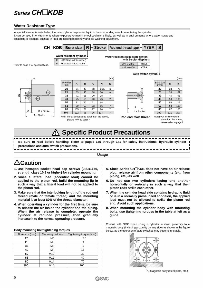
Water Resistant Type
CHKDB Bore size Rod end thread typeStroke Y7BA SR
NBR Seal (nitrile rubber)FKM Seal (fluoro rubber)
RV
Water resistant cylinder
Auto switch symbol
ø20 and 25ø32 to ø100
F9BAY7BA
Water resistant solid state switchwith 2-color display
20253240506380
100
A
61 63 71 75 81 90105132
Bore size(mm) B
4345515560677896
C
1818202021232736
N
26.530 38 45 55 66 86
104
S
66777777
(mm)
g
h + Stroke
S
C B + Stroke
A + Stroke
øN
Refer to page 2 for specifications.
20253240506380
100
g
33 36 45 50 56 68 87111
Bore size(mm) h
76 81 96105116135165207
(mm)
Rod end male thread
5. Since Series CHKDB does not have an air release plug, release air from other components (e.g. from piping, etc.) as well.
6. Do not use two cylinders facing one another horizontally or vertically in such a way that their piston rods strike each other.
7. When the cylinder head side contains hydraulic fluid or is in a normally pressurized condition, the applied load must not be allowed to strike the piston rod end. Avoid such applications.
8. When mounting the cylinder body with mounting bolts, use tightening torques in the table at left as a guide.
Usage
Caution
Specific Product Precautions
Body mounting bolt tightening torquesBore size (mm) Mounting bolt size Tightening torque (N⋅m)
20253240506380
100
Magnetic body (steel plate, etc.)
A special scraper is installed on the basic cylinder to prevent liquid in the surrounding area from entering the cylinder.It can be used in environments where exposure to machine tool coolants is likely, as well as in environments where water spray and splashing is frequent, such as in food processing machinery and car washing equipment.
Be sure to read before handling. Refer to pages 135 through 141 for safety instructions, hydraulic cylinder precautions and auto switch precautions.
2.547
16304070
100
Consult with SMC when using a cylinder in close proximity to a magnetic body (including proximity on any side) as shown in the figure below, as the operation of auto switches may become unstable.
Series CHKDB
5
1. Use hexagon socket head cap screws (JISB1176, strength class 10.9 or higher) for cylinder mounting.
2. Since a lateral load (eccentric load) cannot be applied to the piston rod, build the mounting jig in such a way that a lateral load will not be applied to the piston rod.
3. Make sure that the interlocking length of the rod end thread (male or female thread) and the mounting material is at least 80% of the thread diameter.
4. When operating a cylinder for the first time, be sure to release the air inside the cylinder and the piping. When the air release is complete, operate the cylinder at reduced pressure, then gradually increase it to the normal operating pressure.
Note) For all dimensions other than the above, please refer to page 7.
Note) For all dimensions other than the above, please refer to page 7.
M5M5M6M8
M10M12M14M16

6
Construction
Parts listNo.
1
2
3
4
5
6
7
8
9
10
11
12
13
14
Description
Rod cover
Head cover
Cylinder tube
Piston rod
Piston
Bushing
Back-up ring
Magnet
Magnet plate
Scraper
Rod seal
Piston seal
Tube gasket
Piston gasket
Material
Aluminum alloy
Aluminum alloy
Aluminum alloy
Stainless steel
Copper alloy
Resin
—
Stainless steel
NBR
Note
Black anodized
Black anodized
Hard anodized
Hard chromiumelectroplated
With switch only
With switch only
ø32 to ø100
Without auto switch
ø20 to ø25
Compact Hydraulic Cylinder: 10MPa Series CHKDB
ø20 & ø25: Stainless steelø32 to ø100: Carbon steel
Replacement parts: Seal kits
20
25
32
40
50
63
80
100
Bore size (mm) Seal kit no.
CHKD20-PS
CHKD25-PS
CHKD32-PS
CHKD40-PS
CHKD50-PS
CHKD63-PS
CHKD80-PS
CHKD100-PS
∗ Seal kits consist of items 7, 10, 11, 12 and 13, and can be ordered by using the seal kit number for each bore size.
Nos. 7, 10, 11, 12, and13 from the chart at left
Kit components

Dimensions
4-øK through8-øL counter bore
F with effective thread depth G F with effective thread depth G
4-øK through8-øL counter bore
E
J
M
E
J
M
øD
H
C B + Stroke
h + Stroke
A + Stroke
R
R
Q
c
ab
ge
Q
2-Rc P
Width across flats f
Rod endmale thread
CHKDB20 & 25 CHKDB32 to 100
Bore size (mm)
20
25
32
40
50
63
80
100
Bore size (mm)
20
25
32
40
50
63
80
100
A
51
53
61
65
71
80
95
122
B
43
45
51
55
60
67
78
96
C
8
8
10
10
11
13
17
26
D
12
14
18
22.4
28
35.5
45
56
E
10
12
14
19
24
30
41
50
M8 x 1.25
M10 x 1.5
M12 x 1.75
M16 x 2
M20 x 2.5
M27 x 3
M30 x 3.5
M39 x 4
G
10
12
15
20
24
33
36
45
H
6
6
7
7
8
9
14
21
J
30
36
47
52
58
69
86
106
K
5.5
5.5
6.6
9
11
13
15
17
9.5 depth 5.4
9.5 depth 5.4
11 depth 6.5
14 depth 8.6
17.5 depth 10.8
20 depth 13
23 depth 15.2
26 depth 17.5
a
11
14
21
26
31
41
56
71
b
15
18
25
30
35
45
60
75
c
M10 x 1.25
M12 x 1.25
M16 x 1.5
M20 x 1.5
M24 x 1.5
M30 x 1.5
M39 x 1.5
M48 x 1.5
e
6
6
7
7
8
9
14
21
f
10
12
14
19
24
30
41
50
h
66
71
86
95
106
125
155
197
g
23
26
35
40
46
58
77
101
M
43
49
63
71
81
97
117
142
P
1/8
1/8
1/4
1/4
1/4
1/4
3/8
3/8
Q
16.5
17
19.5
20.5
22
25.5
30
36
R
6
8
10
10
10
10
15
15
Note 1) Body dimensions are the same with or without auto switches.
(mm)
(mm)Rod end male threads
F L
7
Series CHKDB
Auto Switches: Proper Mounting Positions and Mounting Heights for Stroke End Detection
SMCD-A90
SMC D-A90
SM
C
SM
C
SM
C
SM
C
D-A9D-F9D-F9W
D-Z7D-Z8D-Y5D-Y7D-Y7W
D-Y6D-Y7VD-Y7WV
D-A9VD-F9VD-F9WV
D-F9BAL
D-Y7BAL
Approx. MA
Approx. MA
B
B
B
A
A
A
B
B
B
A
A
A
Approx. MA
ø20 & ø25 Proper auto switch mounting positions
Bore size(mm)
D-A9D-A9V
D-F9D-F9VD-F9WD-F9WV
D-F9BAL
2025
A89
B1516
A1213
A1112
B1920
B1819
(mm)
Auto switch mounting heights
Bore size(mm)
D-A9VD-F9VD-F9WV D-F9BAL
2025
2527
2527
27.529.5
(mm)
ø32 to ø100
Auto switch mounting heights (mm)
Series CH KDBAuto Switch SpecificationsRefer to "Auto Switch Guide" CAT.E274-A for detailed specifications.
Bore size(mm)
D-Y7BAL
MA32.537 43 51.562 74.5
3240506380
100
8
Proper auto switch mounting positions (mm)
Bore size(mm)
3240506380
100
D-Z7, D-Z8, D-Y5D-Y, D-Y7D-Y7V, D-Y7WVD-Y7BAL
A10121316.518.526.5
B16.518.522.5263544.5
MA MA MA

9
Auto Switch Mounting
Series CHKDB
Caution
M2.5 x 4l(included with auto switch)
When mounting auto switches, they should be inserted into the cylinder's switch mounting groove from the direction shown in the drawing below. After setting in the mounting position, use a flat head watchmakers screw driver to tighten the set screw that is included.
When tightening the auto switch mounting screw, use a watchmakers screw driver with a handle about 5 to 6mm in diameter.Also, tighten with a torque of 0.1 to 0.2N·m for types D-A9 and D-F9, and 0.05 to 0.1N·m for types D-Z7, D-Z8, D-Y5, D-Y6 and D-Y7. As a rule, the mounting screw should be turned about 90° past the point at which tightening can first be felt.
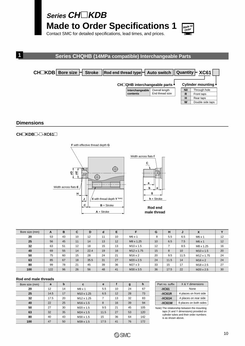
Series CHQHB (14MPa compatible) Interchangeable Parts
Rod end thread type Auto switch Quantity XC61Stroke
Overall lengthEnd thread size
Interchangeablecontents
CHQHB interchangeable partsThrough holeFront tapsRear tapsDouble side taps
NilRHW
Cylinder mounting
Dimensions
CHKDB--XC61
Bore size (mm)
F with effective thread depth G
X with thread depth Y Note)
B + Stroke
h + Stroke
A + Stroke
Width across flats E
Width across flats f
20
25
32
40
50
63
80
100
A
53
56
63
69
75
85
99
122
B
43
45
51
55
60
67
78
96
C
10
11
12
14
15
18
21
26
d
11
13
15
19
24
31
39
48
D
12
14
18
22.4
28
35.5
45
56
E
10
12
13
16
21
27
36
41
G
8
10
12
15
20
24
33
36
H
5.5
6.5
7
8
9.5
11.5
15
17.5
J
6.5
7.5
8.5
10
11.5
14
17
22
Y
12
12
16
20
24
24
27
30
F
M6 x 1
M8 x 1.25
M10 x 1.5
M12 x 1.75
M16 x 2
M20 x 2.5
M27 x 3
M30 x 3.5
X
M6 x 1
M6 x 1
M8 x 1.25
M10 x 1.5
M12 x 1.75
M16 x 2
M18 x 2.5
M20 x 2.5
Bore size (mm)
20
25
32
40
50
63
80
100
a
12
14.5
17.5
22
27
32
40
47
b
14
17
20
25
30
35
43
50
c
M8 x 1
M10 x 1.25
M12 x 1.25
M16 x 1.5
M20 x 1.5
M24 x 1.5
M30 x 1.5
M39 x 1.5
e
5.5
6.5
7
8
9.5
11.5
15
17.5
f
10
12
13
16
21
27
36
41
g
24
28
32
39
45
53
64
76
h
67
73
83
94
105
120
142
172
Part no. suffix X & Y dimensions
None
4 places on front side
4 places on rear side
8 places on both sides
Note) The relationship between the mounting taps (X and Y dimensions) provided on cylinder tubes and their order numbers is as shown above.
H
øD ød
J
C
C
a
b
g
e
Rod endmale thread
1
Rod end male threads
-XC61
-XC61R
-XC61H
-XC61W
Made to
Order
Series CHKDBMade to Order Specifications 1Contact SMC for detailed specifications, lead times, and prices.
10
CHKDB Bore size

Intermediate strokes in 5mm increments can be manufactured by installing spacers inside standard stroke cylinders.
CHKDB Bore size Rod end thread type Auto switch Quantity XC63Stroke
Applicable tubeFor 75mm strokeFor 100mm stroke
Stroke55, 60, 65, 7080, 85, 90, 95
Intermediate stroke
CHKDB--XC63
StrokeBore size(mm)
32
40
50
63
80
100
A
136
140
146
155
170
197
A
—
165
171
180
195
222
B
126
130
135
142
153
171
B
—
155
160
167
178
196
55, 60, 65, 70 80, 85, 90, 95
B
A
Note) Dimensions other than those highlighted above are standard.
Intermediate Stroke Type2
Dimensions
Made toOrder
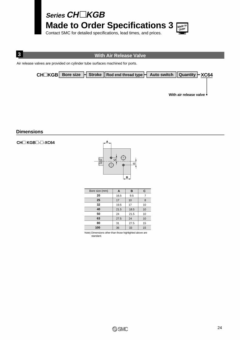
Series CH KDBMade to Order Specifications 2Contact SMC for detailed specifications, lead times, and prices.
11

Air release valves are provided on cylinder tube surfaces machined for ports.
CHKDB Bore size Rod end thread type Auto switch Quantity XC64Stroke
With air release valve
CHKDB--XC64
Bore size (mm)
20
25
32
40
50
63
80
100
A
16.5
17
19.5
20.5
22
25.5
30
36
C
7
8
10
10
10
10
15
15
B
14.5
15
17
17.5
19.5
22
26.5
33
A
B
C
C
With Air Release Valve3
Dimensions
Note) Dimensions other than those highlighted above are standard.
Made toOrder
Series CHKDBMade to Order Specifications 3Contact SMC for detailed specifications, lead times, and prices.
12

Applicable Auto Switches: Refer to "Auto Switch Guide" CAT.E-274-A for further details on each auto switch.Refer to pages 117 and 118 for auto switch circuit diagrams.
Bore sizes ø20 and ø25Auto switchmounting bracket (screws) part nos.
Type Special function
Load voltage
PerpendicularA90VA93VA96VF9NVF9PVF9BV
F9NWVF9PWVF9BWV
—
In-lineA90A93A96F9NF9PF9B
F9NWF9PWF9BWF9BA
Auto switch typeElectrical entry direction Applicable
loadDC
24V
—
24V
100V or less100V
—
—
AC
Indi
cato
rlig
htElectricalentry
Wiring(output)
0.5(Nil)
3(L)
5(Z)
2-wire
3-wire (NPN equiv.)
3-wire (NPN)3-wire (PNP)
2-wire3-wire (NPN)3-wire (PNP)
2-wire
GrommetNo
Yes
YesGrommet
Water resistant (2-color display)
Diagnosticindication
(2-color display)
—
—
Ree
dsw
itch
So
lid s
tate
sw
itch
—
IC circuit—
IC circuit
IC circuit
—
IC circuit
—
RelayPLC
RelayPLC
———
Type Special functionLoad voltage
Perpendicular———
Y69AY7PVY69B
Y7NWVY7PWVY7BWV
—
In-lineZ76Z73Z80
Y59AY7P
Y59BY7NWY7PWY7BWY7BA
Auto switch typeElectrical entry direction
Lead wire length (m)∗Applicable
loadDC
—
24V
24V
5V12V
5V, 12V
5V, 12V
12V
5V, 12V
12V
—100V
100V or less
—
AC
Indi
cato
rlig
htElectricalentry
Wiring(output)
0.5(Nil)
3(L)
5(Z)
3-wire (NPN equiv.)
2-wire
3-wire (NPN)3-wire (PNP)
2-wire3-wire (NPN)3-wire (PNP)
2-wire
GrommetYes
No
YesGrommet
Water resistant (2-color display)
Diagnosticindication
(2-color display)
—
—
Ree
dsw
itch
So
lid s
tate
sw
itch
—
IC circuit—
IC circuit
IC circuit
—
IC circuit
—
RelayPLC
RelayPLC
——
Bore sizes(mm)
Mountingbracketpart no.
Applicable switches
Reed switches
Solid stateswitches
20 & 25
32 to 100
BHK1-020
BHK2-032
D-A9D-A9V
D-Z7D-Z8
D-F9D-F9VD-F9WD-F9WVD-F9BAL
D-Y5D-Y6D-Y7D-Y7VD-Y7WD-Y7WVD-Y7BAL
Note) For cylinders with auto switches, the switches (already attached to mounting brackets) are packed together with the cylinder for shipment, but are not mounted on the cylinder.Bore sizes ø32 to ø100
How to Order
CHKGB
CHDKGB
32 30
32 30 Z73
Without auto switch (built-in magnet)Nil
Auto switch type
With Auto Switch
With auto switch(built-in magnet)
Mounting: Basic type
Bore size20253240506380100
20mm 25mm 32mm 40mm 50mm 63mm 80mm100mm
Female threadMale thread
NilM
Rod end thread type
2 pcs.1 pc.
"n" pcs.
NilSn
Number of auto switches
Cylinder stroke (mm)Refer to the standard stroke table on page 14.
∗ Lead wire length symbols: 0.5m .... Nil (Example) A933m ....... L (Example) A93L5m........ Z (Example) F9NWZ
∗ Lead wire length symbols: 0.5m ....... Nil (Example) Y59A3m .......... L (Example) Y59AL5m .......... Z (Example) Y59AZ
Lead wire length (m)∗
—
—
∗ Select applicable auto switch models from the table below.
Note) Solid state switches marked "" are produced upon receipt of order.
Note) Solid state switches marked "" are produced upon receipt of order.
5V, 12V12V5V
5V, 12V
12V
5V, 12V
12V
Compact Hydraulic Cylinder
Series CHKGBø20, ø25, ø32, ø40, ø50, ø63, ø80, ø100
16MPa
13

Action
Fluid
Nominal pressure
Proof pressure
Maximum allowable pressure
Minimum operating pressure
Ambient and fluid temperature
Piston speed
Cushion
Rod end thread
Thread tolerance
Stroke length tolerance
Mounting type
Mounting
Specifications
Standard Strokes
Double acting/Single rod type
Hydraulic fluid
16MPa
24MPa
16MPa
0.3MPa
Without auto switch: –10° to 80°C
With auto switch: –10° to 60°C
8 to 100mm/s
None
Female thread, Male thread
JIS class 2
mm
Basic type
Through hole
+0.8 0
Bore sizes (mm)
20 & 25
32
40, 50, 63, 80, 100
Standard strokes (mm)
5, 10, 15, 20, 25, 30, 35, 40, 45, 50
5, 10, 15, 20, 25, 30, 35, 40, 45, 50, 75
5, 10, 15, 20, 25, 30, 35, 40, 45, 50, 75, 100
• Light and compact aluminum body.
• Auto switch can be mounted.
• Auto switch mounting does not affect overall length.
• A wide range of operating pressures, bore sizes, and standard strokes make wide selections possible.
Made to
Order
JIS symbol
Manufacture of Intermediate Stroke Cylinders Hydraulic Fluid Compatibility
Minimum Strokes for Auto Switch Mounting
D-Z7D-Z8
No. of auto switches
1 pc.
2 pcs.
5
10
D-Y5, D-Y7VD-Y6D-Y7
5
5
D-Y7WD-Y7WV
10
10
15
15
D-A9, D-F9WD-A9V, D-F9WV
D-F9D-F9V
No. of auto switches
1 pc.
2 pcs.
5
10
5
5
15
15
Auto switch type
D-F9BAL
D-Y7BAL
ø20 & ø25
Auto switch type
ø32 to ø100
Pages 22 to 24
Note) Refer to page 136 for definitions of terms related to pressure.
∗ Contact SMC.
Hydraulic fluid Compatibility
Compatible
Compatible
Compatible
∗Not compatible
Standard mineral hydraulic fluid
W/O hydraulic fluid
O/W hydraulic fluid
Water/Glycol hydraulic fluid
Phosphate hydraulic fluid
Intermediate strokes in 5mm increments can be manufactured by installing spacers inside standard stroke cylinders. 55, 60, 65 and 70mm stroke cylinders have the same overall length as a 75mm stroke cylinder, and 80, 85, 90 and 95mm stroke cylinders have the same length as a 100mm stroke cylinder.Refer to the Made to Order Specifications on page 23 for the ordering procedure.
Compact Hydraulic Cylinder: 16MPa Series CHKGB
14

Theoretical Output
Bore size(mm)
Rod size(mm)
Piston area(mm²)
Operatingdirection
OUT
IN
OUT
IN
OUT
IN
OUT
IN
OUT
IN
OUT
IN
OUT
IN
OUT
IN
20
25
32
40
50
63
80
100
12
14
18
22.4
28
35.5
45
56
314
201
490
336
804
549
1256
862
1963
1347
3117
2127
5026
3436
7853
5390
3.5
1099
704
1715
1176
2814
1922
4396
3017
6871
4715
10910
7445
17591
12026
27486
18865
10
3140
2010
4900
3360
8040
5490
12560
8620
19630
13470
31170
21270
50260
34360
78530
53900
16
5024
3216
7840
5376
12864
8784
20096
13792
31408
21552
49872
34032
80416
54976
125648
86240
7
2198
1407
3430
2352
5628
3843
8792
6034
13741
9429
21819
14889
35182
24052
54971
37730
Unit: N
(mm)
Theoretical output (N) = Pressure (MPa) x Piston area (mm²)
Part no.
NTH-025
NTH-032
NTH-040
NTH-050
NTH-060
NTH-080
NTH-100
NTH-125
Bore size (mm)
20
25
32
40
50
63
80
100
B
17
19
22
27
32
41
55
70
C
19.6
21.9
25.4
31.2
37
47.3
63.5
80.8
D
16.5
18
21
26
31
40
54
69
H
6
7
10
12
14
17
20
26
d
M10 x 1.25
M12 x 1.25
M16 x 1.5
M20 x 1.5
M24 x 1.5
M30 x 1.5
M39 x 1.5
M48 x 1.5
Operating pressure (MPa)
Optional Parts
Rod end nut
Weights
Bore size(mm)
20
25
32
40
50
63
80
100
Standard stroke (mm)
5
221
312
581
927
1351
1813
3870
7188
10
242
339
625
986
1430
1936
4053
7457
15
263
366
669
1045
1509
2059
4236
7726
20
284
393
713
1104
1588
2182
4419
7995
25
305
420
757
1163
1667
2305
4602
8264
30
326
447
801
1222
1746
2428
4785
8533
35
347
474
845
1281
1825
2551
4968
8802
40
368
501
889
1340
1904
2674
5151
9071
45
389
528
933
1399
1983
2797
5334
9340
50
410
555
977
1458
2062
2920
5517
9609
75
—
—
1197
1753
2457
3535
6432
10954
100
—
—
—
2048
2852
4150
7347
12299
Unit: g
Series CHKGB
15
d JIS class 2 thread
H B
CøD
30°

Mounting Bolts for CHKGB
55
60
65
70
75
80
85
90
95
100
55
60
65
70
75
80
85
90
95
100
65
70
75
80
85
90
95
100
105
110
135
75
80
85
90
95
100
105
110
115
120
145
170
D D
M5 x 55l
x 60l
x 60l
x 70l
x 75l
x 80l
x 85l
x 90l
x 95l
x 100l
M5 x 55l
x 60l
x 60l
x 70l
x 75l
x 80l
x 85l
x 90l
x 95l
x 100l
M6 x 65l
x 70l
x 75l
x 80l
x 85l
x 90l
x 95l
x 100l
x 105l
x 110l
x 135l
M8 x 75l
x 80l
x 85l
x 90l
x 95l
x 100l
x 105l
x 110l
x 115l
x 120l
x 145l
x 170l
80
85
90
95
100
105
110
115
120
125
150
175
85
90
95
100
105
110
115
120
125
130
155
180
100
105
110
115
120
125
130
135
140
145
170
195
120
125
130
135
140
145
150
155
160
165
190
215
M10 x 80l
x 85l
x 90l
x 95l
x 100l
x 105l
x 110l
x 115l
x 120l
x 125l
x 150l
x 175l
M12 x 85l
x 90l
x 95l
x 100l
x 105l
x 110l
x 115l
x 120l
x 125l
x 130l
x 155l
x 180l
M14 x 100l
x 105l
x 110l
x 115l
x 120l
x 125l
x 130l
x 135l
x 140l
x 145l
x 170l
x 195l
M16 x 120l
x 125l
x 130l
x 135l
x 140l
x 145l
x 150l
x 155l
x 160l
x 165l
x 190l
x 215l
DC
Mounting bolt
Mounting bolt diagramThrough hole type mounting bolts are available.How to order: Add "Bolt" in front of the bolts to be used. Example: M8 x 80l 4 pcs.
CHKGB20
CHKGB25
CHKGB32
CHKGB40
CModel Mounting bolt
12.4
10.4
10.5
13.5
CHKGB50
CHKGB63
CHKGB80
CHKGB100
CModel Mounting bolt
15.5
16
22
26.5
–5 (M)
–10 (M)
–15 (M)
–20 (M)
–25 (M)
–30 (M)
–35 (M)
–40 (M)
–45 (M)
–50 (M)
–5 (M)
–10 (M)
–15 (M)
–20 (M)
–25 (M)
–30 (M)
–35 (M)
–40 (M)
–45 (M)
–50 (M)
–5 (M)
–10 (M)
–15 (M)
–20 (M)
–25 (M)
–30 (M)
–35 (M)
–40 (M)
–45 (M)
–50 (M)
–75 (M)
–5 (M)
–10 (M)
–15 (M)
–20 (M)
–25 (M)
–30 (M)
–35 (M)
–40 (M)
–45 (M)
–50 (M)
–75 (M)
–100 (M)
–5 (M)
–10 (M)
–15 (M)
–20 (M)
–25 (M)
–30 (M)
–35 (M)
–40 (M)
–45 (M)
–50 (M)
–75 (M)
–100 (M)
–5 (M)
–10 (M)
–15 (M)
–20 (M)
–25 (M)
–30 (M)
–35 (M)
–40 (M)
–45 (M)
–50 (M)
–75 (M)
–100 (M)
–5 (M)
–10 (M)
–15 (M)
–20 (M)
–25 (M)
–30 (M)
–35 (M)
–40 (M)
–45 (M)
–50 (M)
–75 (M)
–100 (M)
–5 (M)
–10 (M)
–15 (M)
–20 (M)
–25 (M)
–30 (M)
–35 (M)
–40 (M)
–45 (M)
–50 (M)
–75 (M)
–100 (M)
16
Compact Hydraulic Cylinder: 16MPa Series CHKGB

1. Use hexagon socket head cap screws (JISB1176, strength class 10.9 or higher) for cylinder mounting.
2. Since a lateral load (eccentric load) cannot be applied to the piston rod, build the mounting jig in such a way that a lateral load will not be applied to the piston rod.
3. Make sure that the interlocking length of the rod end thread (male or female thread) and the mounting material is at least 80% of the thread diameter.
4. When operating a cylinder for the first time, be sure to relase the air inside the cylinder and the piping. When the air release is complete, operate the cylinder at reduced pressure, then gradually increase it to the normal operating pressure.
5. Since Series CHKGB does not have an air release plug, release air from other components (e.g. from piping, etc.) as well.
6. Do not use two cylinders facing one another horizontally or vertically in such a way that their piston rods strike each other.
7. When the cylinder head side contains hydraulic fluid or is in a normally pressurized condition, the applied load must not be allowed to strike the piston rod end. Avoid such applications.
8. When mounting the cylinder body with mounting bolts, use tightening torques in the table at left as a guide.
Usage
Caution
Specific Product Precautions
Body mounting bolt tightening torques
Bore size (mm) Mounting bolt size20253240506380
100
Magnetic body (steel plate etc.)
Tightening torque N⋅m
Consult with SMC when using a cylinder in close proximity to a magnetic body (including proximity on any side) as shown in the figure below, as the operation of auto switches may become unstable.
17
Series CHKGB
Be sure to read before handling. Refer to pages 135 through 141 for safety instructions, hydraulic cylinder and auto switch precautions.
M5M5M6M8
M10M12M14M16
3.04.9
1020405080
120

18
Construction
Parts listNo.
1
2
3
4
5
6
7
8
9
10
11
12
13
14
15
Description
Rod cover
Head cover
Cylinder tube
Piston rod
Piston
Bushing
Back-up ring
Magnet
Magnet plate
Switch mounting bracket
Scraper
Rod seal
Piston seal
Tube gasket
Piston gasket
Material
Aluminum alloy
Aluminum alloy
Aluminum alloy
Stainless steel
Copper alloy
Resin
—
Stainless steel
Aluminum alloy
NBR
Note
Black anodized
Black anodized
Hard anodized
Hard chromium electroplated
With switch only
With switch only
With switch only
With back-up ring
ø32 to ø100
Without auto switch
ø20 to ø25
Compact Hydraulic Cylinder: 16MPa Series CHKGB
ø20 & ø25: Stainless steelø32 to ø100: Carbon steel
Replacement parts: Seal kitsBore size (mm)
20
25
32
40
50
63
80
100
Seal kit no.
CHKG20-PS
CHKG25-PS
CHKG32-PS
CHKG40-PS
CHKG50-PS
CHKG63-PS
CHKG80-PS
CHKG100-PS
Nos. 7, 11, 12, 13 and14 from the chart at left
∗ Seal kits consist of items 7, 11, 12, 13 and 14 and can be ordered by using the seal kit number for each bore size.
Kit components

Dimensions
4-øK through
F with effective thread depth G
8-øL counter bore
E
J
M
øD
H
C B + Stroke h + Stroke
A + StrokeR
R
c
a
bg
e
Q S
2-Rc P
Width across flats f
Rod endmale thread
20
25
32
40
50
63
80
100
Bore size (mm)
20
25
32
40
50
63
80
100
Bore size (mm)
A
51
53
66
75
81
90
105
132
B
43
45
56
65
70
77
88
106
C
8
8
10
10
11
13
17
26
D
12
14
18
22.4
28
35.5
45
56
E
10
12
14
19
24
30
41
50
F
M8 x 1.25
M10 x 1.5
M12 x 1.75
M16 x 2
M20 x 2.5
M27 x 3
M30 x 3.5
M39 x 4
G
10
12
15
20
24
33
36
45
H
6
6
7
7
8
9
14
21
J
30
36
47
52
58
69
86
106
K
5.5
5.5
6.6
9
11
13
15
17
9.5 depth 5.4
9.5 depth 5.4
11 depth 6.5
14 depth 8.6
17.5 depth 10.8
20 depth13
23 depth 15.2
26 depth 17.5
a
11
14
21
26
31
41
56
71
b
15
18
25
30
35
45
60
75
c
M10 x 1.25
M12 x 1.25
M16 x 1.5
M20 x 1.5
M24 x 1.5
M30 x 1.5
M39 x 1.5
M48 x 1.5
e
6
6
7
7
8
9
14
21
f
10
12
14
19
24
30
41
50
h
66
71
91
105
116
135
165
207
g
23
26
35
40
46
58
77
101
M
43
49
63
71
81
100
121
146
P
1/8
1/8
1/4
1/4
1/4
1/4
3/8
3/8
Q
16.5
17
19.5
21.5
24
27.5
31
36
R
6
8
10
10
10
10
15
15
Note) Body dimensions are the same with or without auto switches.
(mm)
(mm)
S
11.5
12
19.5
21.5
24
27.5
31
36
Rod end male threads
L
Series CHKGB
19

Auto Switches: Proper Mounting Positions and Mounting Heights for Stroke End Detection
D-A9D-F9D-F9W
D-Z7D-Z8D-Y5D-Y7D-Y7W
D-Y6D-Y7VD-Y7WV
D-A9VD-F9VD-F9WV
D-F9BAL
D-Y7BAL
Approx. MA
Approx. MA
B
A
Approx. MA
A
A
A
A
A
B
B
B
B
B
SMCD-A90
SMC D-A90
SMCD-A90V
SMCD-A90V
SM
C
SM
C
SM
C
SM
C
Proper auto switch mounting positions
Bore size(mm)
D-A9D-A9V
D-F9D-F9VD-F9WD-F9WV
D-F9BAL
2025
A1213
B1112
A1617
A1516
B1516
B1415
(mm)
Auto switch mounting heightsBore size
(mm)D-A9V D-F9V
D-F9WV D-F9BAL
2025
25.527.5
25.527.5
2830
(mm)
ø20 & ø25
ø32 to ø100
20
Series CHKGBAuto Switch SpecificationsRefer to "Auto Switch Guide" CAT.E274-A for detailed specifications.
Auto switch mounting heights (mm)
Bore size(mm)
D-Y7BAL
MA33 37.543.552 62.575
3240506380
100
Proper auto switch mounting positions (mm)
Bore size(mm)
D-Z7, D-Z8, D-Y5D-Y6, D-Y7D-Y7V, D-Y7WVD-Y7BAL
3240506380
100
A13.519 19 21.524.534.5
B18 21.526.531 39 46.5
MA MA MA

Caution
M2.5 x 4l(included with auto switch)M3 x 6l
(included with switch mounting bracket)
Auto Switch Mounting
When mounting auto switches, they should first be set into the mounting bracket and inserted into the cylinder's switch mounting groove from the direction shown in the drawing below. After setting in the mounting position, use a hexagon wrench to tighten the switch mounting bracket screw that is included.
When tightening the auto switch mounting screw, use a watchmakers screw driver with a handle about 5 to 6 mm in diameter. When tightening the mounting bracket screw, use a 1.5mm hexagon wrench. The tightening torque should be approximately 0.1 to 0.2N·m for types D-A9 and D-F9, and 0.05 to 0.1N·m for types D-Z7, D-Z8, D-Y5, D-Y6 and D-Y7. As a rule, the mounting screw should be turned about 90° past the point at which tightening can first be felt.
21
Series CHKGB

Series CHQHB (14MPa) Interchangeable Parts
CHKGB Bore size Rod end thread type Auto switch Quantity XC62Stroke
Piston rodC dimensionEnd thread sizeF dimension
Interchangeable contents
CHQHB Interchangeable parts Note)
Through holeFront tapsRear tapsDouble side taps
NilRHW
Cylinder mounting
Dimensions
Note) The interchangeable contents are the "C" dimension (from the front end surface to the rod end) and the "F" dimension (rod end thread size).
F with effective thread depth G
CHKGB--XC62
X with thread depth Y Note1)
B + Stroke
h + Stroke
A + Stroke
Width across flats E
Width across flats f
H
øD ød
J
C
c
a
b
g
e
Rod endmale thread
1
Bore size (mm)
20
25
32
40
50
63
80
100
A
53
56
68
79
85
95
109
132
B
43
45
56
65
70
77
88
106
C
10
11
12
14
15
18
21
26
d
11
13
15
19
24
31
39
48
D
12
14
18
22.4
28
35.5
45
56
E
10
12
13
16
21
27
36
41
G
8
10
12
15
20
24
33
36
H
5.5
6.5
7
8
9.5
11.5
15
17.5
J
6.5
7.5
8.5
10
11.5
14
17
22
Y
12
12
16
20
24
24
27
30
F
M6 x 1
M8 x 1.25
M10 x 1.5
M12 x 1.75
M16 x 2
M20 x 2.5
M27 x 3
M30 x 3.5
X
M6 x 1
M6 x 1
M8 x 1.25
M10 x 1.5
M12 x 1.75
M16 x 2
M18 x 2.5
M20 x 2.5
Bore size (mm)
20
25
32
40
50
63
80
100
a
12
14.5
17.5
22
27
32
40
47
b
14
17
20
25
30
35
43
50
c
M8 x 1
M10 x 1.25
M12 x 1.25
M16 x 1.5
M20 x 1.5
M24 x 1.5
M30 x 1.5
M39 x 1.5
e
5.5
6.5
7
8
9.5
11.5
15
17.5
f
10
12
13
16
21
27
36
41
g
24
28
32
39
45
53
64
76
h
67
73
88
104
115
130
152
182
Part no. suffix
-XC62
-XC62R
-XC62H
-XC62W
X & Y dimensions
None
4 places on front side
4 places on rear side
8 places on both sides
Note) The relationship between the mounting taps (X & Y dimensions) provided on cylinder tubes and their order numbers is as shown above.
Rod end male threads
22
Made to
Order
Series CHKGBMade to Order Specifications 1Contact SMC for detailed specifications, lead times, and prices.

CHKGB Bore size Rod end thread type Auto switch Quantity XC63Stroke
Applicable tubeFor 75mm strokeFor 100mm stroke
Strokes55, 60, 65, 7080, 85, 90, 95
Intermediate stroke
CHKGB--XC63
32
40
50
63
80
100
A
141
150
156
165
180
207
A
—
175
181
190
205
232
B
131
140
145
152
163
181
B
—
165
170
177
188
206
B
A
StrokeBore size
(mm)
55, 60, 65, 70 80, 85, 90, 95
Intermediate Stroke Type2
Dimensions
Intermediate strokes in 5mm increments can be manufactured by installing spacers inside standard stroke cylinders.
Note) Dimensions other than those highlighted above are standard.
Made to
Order
Series CHKGBMade to Order Specifications 2Contact SMC for detailed specifications, lead times, and prices.
23
CHKGB Bore size Rod end thread type Auto switch Quantity XC64Stroke
With air release valve
CH KGB--XC64
Bore size (mm)
20
25
32
40
50
63
80
100
A
16.5
17
19.5
21.5
24
27.5
31
36
C
7
8
10
10
10
10
15
15
B
9.5
10
17
18.5
21.5
24
27.5
33
A
B
C
C
With Air Release Valve3
Air release valves are provided on cylinder tube surfaces machined for ports.
Dimensions
Note) Dimensions other than those highlighted above are standard.
Made to
Order
Series CHKGBMade to Order Specifications 3Contact SMC for detailed specifications, lead times, and prices.
24

How to Order
Rod end thread type
2 pcs.1 pc.
"n" pcs
NilSn
Number of auto switches
Without auto switch(built-in magnet )Nil
Auto switch typeBore size
With auto switch(built-in magnet)
Action: Double acting
Mounting: Basic type
25
Compact Hydraulic CylinderDouble Acting/Single Rod
Series CHQBø20, ø32, ø40, ø50, ø63, ø80, ø100
CHQB 50 30 D
CHDQB 50 30 A72DWith Auto Switch
203240506380
100
20mm32mm40mm50mm63mm80mm100mm
3.5MPa
Applicable Auto Switches:
Type Electricalentry
Connector
Connector
Indi
cato
r li
ght
3-wire (NPN equiv.)
Load voltageAuto switch type
—200V
ACDC
Lead wire length (m)∗
0.5(Nil)
3(L)
5(Z)
None(N)
————
—
—————
—
IC circuit
Applicableload
100V or less—
24V or less
—
5V—
5V, 12V12V
5V, 12V
—
——
Yes
Yes
Diagnostic indication(2-color display)
Diagnostic indication(2-color display)
Diagnostic indication(2-color display)Latch type with
diagnostic output(2-color display)
With timer
Water resistant (2-color display)
YesNo
Yes
3-wire (NPN)
2-wire
2-wire
2-wire
IC circuit—
IC circuit
—
Ree
d s
witc
hS
olid
sta
te s
witc
h
—A72A73—
A80A73CA80C
A79W
A96V——
A93VA90V
——
—
A96——
A93A90——
—
—
No
—
— RelayPLC
RelayPLC
12V
24V
24V
Grommet
Grommet
Grommet
Grommet
Wiring(output)
Special function
A76HA72HA73H
—A80H
——
—
ø20 to ø100 ø32 to ø100
Rail mount Direct mount
Perpendicular PerpendicularIn-line In-line
—
—
100V
—
—
—
3-wire (PNP)
3-wire (PNP)
3-wire (NPN)
3-wire (NPN)
4-wire (NPN)
5V, 12V
5V, 12V
5V, 12V
5V, 12V
12V
12V
F7NVF7PVF7BVJ79C
F7NWV———
F7BWVF7BAV
—
—
F79F7PJ79—
F79W—
F7PW—
J79WF7BAF7NT
F79F
F9NVF9PVF9BV
——
F9NWV—
F9PWVF9BWV
——
—
F9NF9PF9B——
F9NW—
F9PWF9BWF9BA
—
—
——
——————————
—
IC circuit
IC circuit
IC circuit
IC circuit
—— — —F7LF —
Refer to "Auto Switch Guide" CAT.E274-A for further details on each auto switch.Refer to pages 117 and 118 for auto switch circuit diagrams.
Cylinder stroke (mm)Refer to the standard stroke table on page 26.
Female threadMale thread
NilM
∗ Select applicable auto switch models from the table below.
∗ Lead wire length symbols: 0.5m ...... Nil (Example) A80C 3 m ....... L (Example) A80CL
Note) Solid state switches marked "" are produced upon receipt of order.
5m ........ Z (Example) A80CZ None ..... N (Example) A80CN

Action
Fluid
Nominal pressure
Proof pressure
Maximum allowable pressure
Minimum operating pressure
Ambient and fluid temperature
Piston speed
Cushion
Rod end thread
Thread tolerance
Stroke length tolerance
Mounting type
Mounting
Double acting/Single rod
Hydraulic fluid
3.5MPa
5.0MPa
3.5MPa
0.3MPa
Without auto switch: –10° to 80°C
With auto switch: –10° to 60°C
8 to 100mm/s
None
Standard: Female thread, Male thread
JIS class 2
mm
Basic type
Through hole
+1.0 0
Bore size (mm)
20
32
40
50
63
80
100
Standard strokes (mm)
Note) Consult with SMC regarding the manufacture of strokes other than the above.
5, 10, 15, 20, 25, 30, 35, 40, 45, 50
5, 10, 15, 20, 25, 30, 35, 40, 45, 50, 75, 100
5, 10, 15, 20, 25, 30, 35, 40, 45, 50, 75, 100
10, 15, 20, 25, 30, 35, 40, 45, 50, 75, 100
10, 15, 20, 25, 30, 35, 40, 45, 50, 75, 100
10, 15, 20, 25, 30, 35, 40, 45, 50, 75, 100
10, 15, 20, 25, 30, 35, 40, 45, 50, 75, 100
Made to
OrderPage 34
Specifications
Standard Strokes
Hydraulic Fluid Compatibility
JIS symbol
• 3.5MPa hydraulic cylinder with short overall length
• Makes more compact jigs and equipment a reality
• Auto switch can be mounted.• Auto switch mounting does
not affect overall length.
Auto Switch Mounting Bracket Part Nos.
Bore sizes(mm)
Mountingbracketpart no.
NoteApplicable Auto Switches
Reed Switches Solid State Switches
20
32, 40, 5063, 80, 100
BQ – 1
BQ – 2
• Switch mounting screw (M3 x 0.5 x 8l) • Square nut
• Switch mounting screw (M3 x 0.5 x 10l) • Switch spacer • Switch mounting nut
D–A7, D–A80 D–A73C, D–A80CD–A7H, D–A80HD–A79W
D–F7, D–J79D–F7V, D–J79C D–F7W, D–J79W D–F7WV, D–F7BA D–F7F, D–F7NTL
(mm)
No. ofauto
switches
1 pc. 5
5
5
10
10
15
10
10
15
20
15
15
20
202 pcs.
D-F7VD-J79CD-F9D-F9V
D-F9WD-F9WVD-F7WD-F7WVD-J79WD-F9BALD-F7BAVL
D-F7BALD-F7NTLD-F79F
D-F7D-J79
D-F7LFD-A79W
D-A7D-A80D-A73CD-A80CD-A7HD-A80HD-A9D-A9V
[Stainless Steel Mounting Screw Kit]The following stainless steel mounting screw kit (including nuts) is available to meet special operating environment conditions. (Please note that auto switch spacers are not included and must be ordered separately.)
Stainless steel mounting screw kit: BBA2 for D-A7, D-A8, D-F7, and D-J7 auto switches
When a cylinder is ordered with waterproof type D-F7BAL switches, they are mounted on the cylinder with stainless steel screws. When the same switches are ordered seperatly, the aove mounting screw kits BBA2 are automatically included with the switches.
Note) Refer to page 136 for definitions of terms related to pressure.
Minimum Strokes for Auto Switch Mounting
26
Compact Hydraulic Cylinder Double Acting/Single Rod: 3.5MPa Series CHQB
Hydraulic fluid Compatibility
Compatible
Compatible
Compatible
Not compatible
Not compatible
Standard mineral hydraulic fluid
W/O hydraulic fluid
O/W hydraulic fluid
Water/Glycol hydraulic fluid
Phosphate hydraulic fluid

Theoretical output (N) = Pressure (MPa) x Piston area (mm²)
Bore size(mm)
Piston area(mm²)
Rod size(mm)
20
32
40
50
63
80
100
10
16
16
20
20
25
30
OUT
IN
OUT
IN
OUT
IN
OUT
IN
OUT
IN
OUT
IN
OUT
IN
314
235
804
603
1256
1055
1963
1649
3117
2803
5026
4535
7853
7147
1
314
235
804
603
1256
1055
1963
1649
3117
2803
5026
4535
7853
7147
471
352
1206
904
1884
1582
2944
2473
4675
4204
7539
6802
11779
10720
628
470
1608
1206
2512
2110
3926
3298
6234
5606
10052
9070
15706
14294
785
587
2010
1507
3140
2637
4907
4122
7792
7007
12565
11337
19632
17867
942
705
2412
1809
3768
3165
5889
4947
9351
8409
15078
13605
23559
21441
1099
822
2814
2110
4396
3692
6870
5771
10909
9810
17591
15872
27485
25014
1.5 2 2.5 3 3.5
Theoretical Output
Weights
Operatingdirection
Operating pressure (MPa)
Bore size(mm)
20
32
40
50
63
80
100
180
330
480
—
—
—
—
Cylinder stroke (mm)
Unit: N
Unit: g
Malethread
additionalweight
5
200
350
500
860
1250
2380
3520
10
220
370
520
890
1290
2470
3630
15
240
390
540
920
1330
2560
3740
20
260
410
560
950
1370
2650
3850
25
280
430
580
980
1410
2740
3960
30
300
450
600
1010
1450
2830
4070
35
320
470
620
1040
1490
2920
4180
40
340
490
640
1070
1530
3010
4290
45
360
510
660
1100
1570
3100
4400
10
52
52
100
100
172
283
50
—
610
760
1250
1770
3550
4950
75
—
710
860
1400
1970
4000
5500
100
Specific Product Precautions
Caution1. Use hexagon socket head cap
screws (JISB1176, strength class 10.9 or higher) for cylinder mounting. (ø20: 2 pcs.; ø32 to ø100: 4 pcs.)
2. Since a lateral load (eccentric load) cannot be applied to the piston rod, build the mounting jig in such a way that a lateral load will not be applied to the piston rod.
3. Make sure that the interlocking length of the rod end thread (male or female thread) and the mounting material is at least 80% of the thread diameter.
4. When operating a cylinder for the first time, be sure to release the air inside the cylinder and the piping. When the air release is complete, operate the cylinder at reduced pressure, then gradually increase it to the normal operating pressure.
5. Since Series CHQB does not have an air release plug, release air from other components (e.g. from piping, etc.) as well.
6. When mounting the cylinder body with mounting bolts, use the tightening torques in the table at right as a guide.
7. Do not use two cylinders facing one another horizontally or verti-cally in such a way that their piston rods strike each other.
8. When the cylinder head side contains hydraulic fluid or is in a normally pressurized condition, the applied load must not be allowed to strike the piston rod end. Avoid such applications.
Usage
Bore size(mm)
203240506380
100
3
3
3
6
11.5
24
34
2
4
4
4
4
4
4
M5 x 0.8
M5 x 0.8
M5 x 0.8
M6 x 1
M8 x 1.25
M10 x 1.5
M10 x 1.5
Mounting bolt Tightening torque
Size N⋅mQty.
Body mounting bolt tightening torques
OUT IN
Be sure to read before handling. Refer to pages 135 through 141 for safety instructions, hydraulic cylinder precautions and auto switch precautions.
27
Series CHQB

Mounting Bolts for CHQB
CH QB20
Model C
7
7
10
12
D
55
60
65
70
75
80
85
90
95
100
70
75
80
85
90
95
100
105
110
115
140
165
75
80
85
90
95
100
105
110
115
120
145
170
90
95
100
105
110
115
120
125
130
155
180
Mounting bolt Model C
15.5
14.5
13.5
D
95
100
105
110
115
120
125
130
135
160
185
100
105
110
115
120
125
130
135
140
165
190
105
110
115
120
125
130
135
140
145
170
195
Mounting bolt
–5D (M)
–10D (M)
–15D (M)
–20D (M)
–25D (M)
–30D (M)
–35D (M)
–40D (M)
–45D (M)
–50D (M)
CHQB63 –10D (M)
–15D (M)
–20D (M)
–25D (M)
–30D (M)
–35D (M)
–40D (M)
–45D (M)
–50D (M)
–75D (M)
–100D (M)
CHQB80 –10D (M)
–15D (M)
–20D (M)
–25D (M)
–30D (M)
–35D (M)
–40D (M)
–45D (M)
–50D (M)
–75D (M)
–100D (M)
CHQB100 –10D (M)
–15D (M)
–20D (M)
–25D (M)
–30D (M)
–35D (M)
–40D (M)
–45D (M)
–50D (M)
–75D (M)
–100 (M)
CH QB32 –5D (M)
–10D (M)
–15D (M)
–20D (M)
–25D (M)
–30D (M)
–35D (M)
–40D (M)
–45D (M)
–50D (M)
–75D (M)
–100D (M)
CH QB40 –5D (M)
–10D (M)
–15D (M)
–20D (M)
–25D (M)
–30D (M)
–35D (M)
–40D (M)
–45D (M)
–50D (M)
–75D (M)
–100D (M)
CH QB50 –10D (M)
–15D (M)
–20D (M)
–25D (M)
–30D (M)
–35D (M)
–40D (M)
–45D (M)
–50D (M)
–75D (M)
–100D (M)
M5 x 55l
x 60l
x 65l
x 70l
x 75l
x 80l
x 85l
x 90l
x 95l
x 100l
M5 x 70l
x 75l
x 80l
x 85l
x 90l
x 95l
x 100l
x 105l
x 110l
x 115l
x 140l
x 165l
M5 x 75l
x 80l
x 85l
x 90l
x 95l
x 100l
x 105l
x 110l
x 115l
x 120l
x 145l
x 170l
M6 x 90l
x 95l
x 100l
x 105l
x 110l
x 115l
x 120l
x 125l
x 130l
x 155l
x 180l
M8 x 95l
x 100l
x 105l
x 110l
x 115l
x 120l
x 125l
x 130l
x 135l
x 160l
x 185l
M10 x 100l
x 105l
x 110l
x 115l
x 120l
x 125l
x 130l
x 135l
x 140l
x 165l
x 190l
M10 x 105l
x 110l
x 115l
x 120l
x 125l
x 130l
x 135l
x 140l
x 145l
x 170l
x 195l
Mounting: Through hole type mounting bolts are available.How to order: Add "Bolt" in front of the bolts to be used.Example: M5 x 50l 4 pcs. Mounting bolt
CD
28
Compact Hydraulic Cylinder Double Acting/Single Rod: 3.5MPa Series CHQB
Mounting bolt diagram
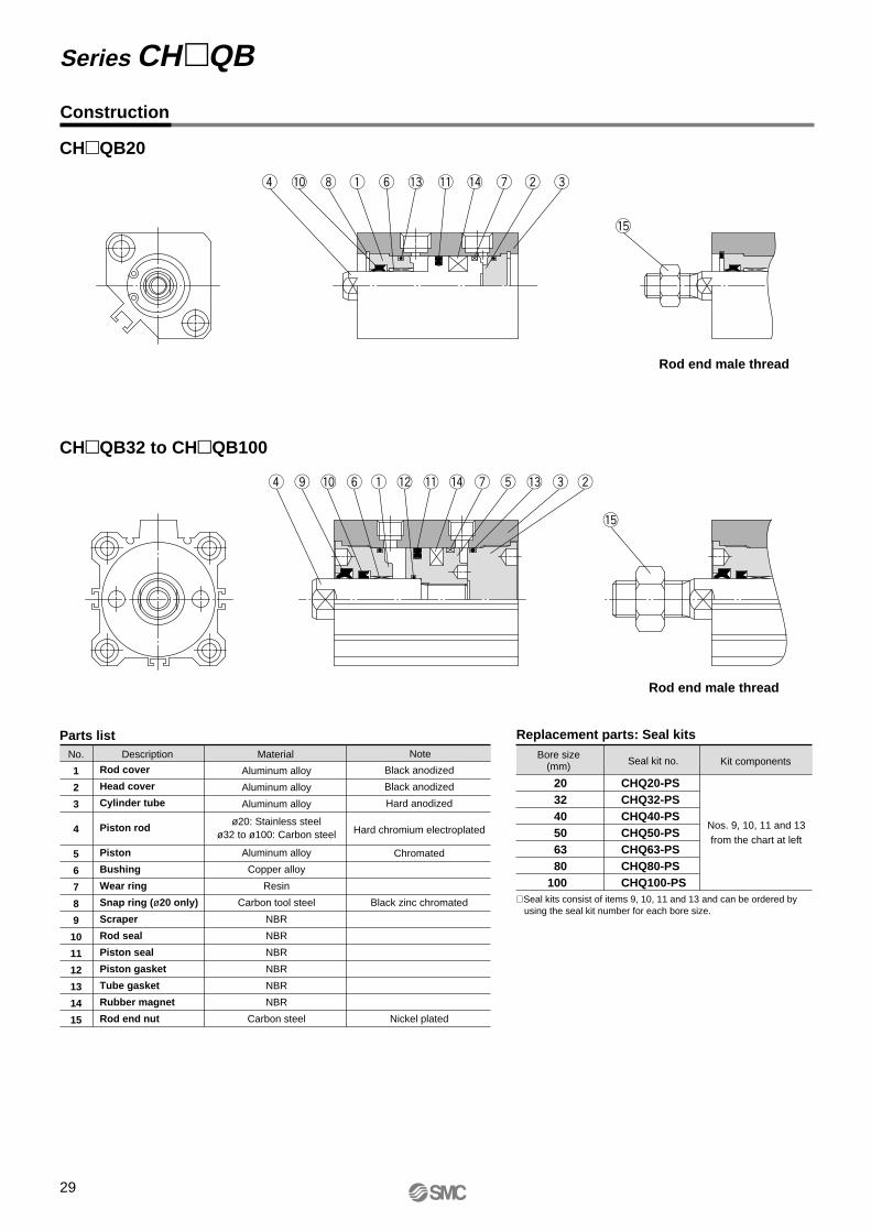
Construction
No.
1
2
3
4
5
6
7
8
9
10
11
12
13
14
15
Description Material Note
Parts list Replacement parts: Seal kits
Rod cover
Head cover
Cylinder tube
Piston rod
Piston
Bushing
Wear ring
Snap ring (ø20 only)
Scraper
Rod seal
Piston seal
Piston gasket
Tube gasket
Rubber magnet
Rod end nut
Aluminum alloy
Aluminum alloy
Aluminum alloy
ø20: Stainless steelø32 to ø100: Carbon steel
Aluminum alloy
Copper alloy
Resin
Carbon tool steel
NBR
NBR
NBR
NBR
NBR
NBR
Carbon steel
Black anodized
Black anodized
Hard anodized
Hard chromium electroplated
Chromated
Black zinc chromated
Nickel plated
Bore size(mm) Seal kit no.
CHQ20-PSCHQ32-PSCHQ40-PSCHQ50-PSCHQ63-PSCHQ80-PSCHQ100-PS
Kit components
Nos. 9, 10, 11 and 13from the chart at left
203240506380
100
CHQB20
CHQB32 to CHQB100
Rod end male thread
Rod end male thread
∗ Seal kits consist of items 9, 10, 11 and 13 and can be ordered by using the seal kit number for each bore size.
29
Series CHQB

ø20
ø32 to ø100
Dimensions
Bore size (mm)
32
40
50
63
80
100
A
73.5
75.5
87
91
100
107
B
65
67
76
80
89
95
C
12
12
15
15
20
24
D
16
16
20
20
25
30
E
45
52
64
77
98
117
F
20
22
25
27
28
29
H
M10 x 1.5
M10 x 1.5
M12 x 1.75
M12 x 1.75
M16 x 2
M20 x 2.5
I
60
69
86
103
132
156
J
4.5
5
7
7
6
6.5
K
14
14
18
18
22
26
L
8.5
8.5
11
11
11
12
N
5.5
5.5
6.6
9
11
11
M
34
40
50
60
77
94
O
9 depth 7
9 depth 7
11 depth 8
14 depth 10.5
17.5 depth 13.5
17.5 depth 13.5
P
Rc 1/8
Rc 1/8
Rc 1/4
Rc 1/4
Rc 3/8
Rc 3/8
S
58.5
66
80
93
112.5
132.5
U
31.5
35
41
47.5
57.5
67.5
Z
14
14
19
19
26
26
(mm)
Bore size (mm)
20
32
40
50
63
80
100
C
15.5
27
27
32
32
37
37
X
18
30
30
35
35
40
40
D
10
16
16
20
20
25
30
K
8
14
14
18
18
22
26
L
23
38.5
38.5
46
46
51
52
H
M8 x 1.25
M14 x 1.5
M14 x 1.5
M18 x 1.5
M18 x 1.5
M22 x 1.5
M26 x 1.5
Rod end male threads (mm)
20 (22)
M6 x 1 with effective thread depth 8
Min. bendingradius of lead wire 10
4824
.5
36 8
3647
2-ø5.5 through4-ø9 counter bore depth 7
4-øN through hole8-øO counter bore
ø10
142050 + Stroke
55 + Stroke5
2-Rc 1/8(port size)
2-P(port size)
K CX
L
øD
H
Rod end male thread
20 (
22)
Min. bendingradius of lead wire 10
Auto switch KME JS∗
Z M E øD
H with effective thread depth C F F
L B + StrokeA + Stroke
26
Connector type
13Connectorauto switch
App
rox.
U∗
10 (11)
øI
10 (1
1)
Approx. U
Compact Hydraulic CylinderDouble Acting/Single Rod: 3.5MPa Series CHQB
Note) • This drawings above show type D-A7 and D-A8 reed switches.• The values shown inside ( ) are for switches other than types D-A7 and D-A8.∗ S and U dimensions for connector type auto switches (D-A7C, D-A80C, and D-J79C) are 7mm greater.
30

Auto Switches: Proper Mounting Positions and Mounting Heights for Stroke End Detection
ø20
D-A7D-A80
D-A73CD-A80CD-J79C
D-A79WD-F7WVD-F7VD-F7BAVL
D-A7HD-A80HD-F7D-J79D-F7WD-J79WD-F7FD-F7NTLD-F7BAL
ø32 to ø100
D-A7*C,D-A80C
SM
CS
MC
D-A7*C,D-A80C
SM
CS
MC
Approx. U
Approx. U
A B
App
rox.
U
BA
App
rox.
UB A B
Approx. U
Approx. U
AA
ppro
x. U
App
rox.
U
A B
A B
A
A B
B
20
32
40
50
63
80
100
D-A7D-A80
D-A9D-A9V
D-F9D-F9VD-F9WD-F9WV
D-A7H, D-A80HD-A73C, D-A80CD-F7D-F7VD-F7W, D-F7WVD-J79D-J79C, D-J79WD-F7BA
D-F7F D-F9BAL
A
20.5
27
26
33.5
33.5
40.5
44.5
B
11.5
20
23
24.5
28.5
30
32.5
A
21
27.5
26.5
34
34
41
45
B
12
20.5
23.5
25
29
30.5
33
A
18
24.5
23.5
31
31
38
42
B
9
17.5
20.5
22
26
27.5
30
A
25
31.5
30.5
38
38
45
49
B
16
24.5
27.5
29
33
34.5
37
A
—
26
25
32.5
32.5
39.5
43.5
B
—
19
22
23.5
27.5
29
31.5
A
—
30
29
36.5
36.5
43.5
47.5
B
—
23
26
27.5
31.5
33
35.5
A
—
29
28
35.5
35.5
42.5
46.5
B
—
22
25
26.5
30.5
32
34.5
A
26
32.5
31.5
39
39
46
50
B
17
25.5
28.5
30
34
35.5
38
D-A79W D-F7NTL
Proper auto switch mounting positions
Bore size(mm)
(mm)
Series CHQBAuto Switch SpecificationsRefer to "Auto Switch Guide" CAT.E 274-A for detailed specifications.
31

Auto switch mounting heights
20
32
40
50
63
80
100
D-A7D-A80
D-F9VD-F9WV D-F9BAL
D-A7HD-A80HD-J79D-J79WD-F7D-F7FD-F7NTLD-F7BALD-F7W
D-A73CD-A80CD-F7WV
U
24.5
31.5
35
41
47.5
57.5
67.5
U
25.5
32.5
36
42
48.5
58.5
68.5
U
31.5
38.5
42
48
54.5
64.5
74.5
U
28
35
38.5
44.5
51
61
71
U
—
27
30.5
36.5
40
50
60
U
—
29
32.5
38.5
42
52
62
U
—
26.5
30
36
39.5
49.5
59.5
U
31
38
41.5
47.5
54
64
74
U
27
34
37.5
43.5
50
60
70
D-J79C D-A79W D-A9VD-F7VD-F7BAVL
Bore size
(mm)
(mm)
ø32 to ø100
D-F9BAL
D-A9D-F9D-F9W
D-A9VD-F9VD-F9WV
Approx. U
Approx. U
B
A
B
A
B
A
32
Compact Hydraulic Cylinder Double Acting/Single Rod: 3.5MPa Series CHQB

Auto Switch Mounting
Mount auto switches in accordance with the procedures shown in the figures below.
ø20 ø32 to ø100
Auto switch mounting screw(M3 x 0.5 x 8l)
Square nut
Auto switch mounting screw (M3 x 0.5 x 10l)
Auto switch spacer
Auto switchmounting nut
Set screw
33
Series CHQB

CH QB XB10Bore size Stroke
Intermediate stroke (using special body)
Dimensions
B + Stroke
A + Stroke
Bore size(mm)
3240506380
100
73.575.5
8791
100107
656776808995
A55 to 100mm strokes
B55 to 100mm strokes
(mm)
1 Intermediate Strokes (Using Special Body) -XB10Symbol
SpecificationsModel
Action
Bore size
Mounting
Auto switch
Other specifications
CHQBDouble acting/Single rod
32, 40, 50, 63, 80, 100mm
Through hole
Mountable
Same as standard double acting single rod
When using an intermediate stroke other than the compact hydraulic cylinder (Series CHQB) standard strokes, it is possible to shorten the overall length and reduce the mounting space by using a special body that does not have spacers installed.
Notes) • Dimensions other than the above are the same as the standard double acting single rod type.
• Applicable strokes are available in 5mm increments.
34
Made to
Order
Series CHQBMade to Order SpecificationsContact SMC for detailed specifications, lead times, and prices.

With Auto Switch
How to Order
Rod end thread type
2 pcs. 1 pc.
"n" pcs.
NilSn
Number of auto switches
Without auto switch(built-in magnetic)Nil
Auto switch type
Bore size
With auto switch(built-in magnet)
Action: Double acting
Model: Double acting/Double rod
Mounting: Basic type
35
Compact Hydraulic CylinderDouble Acting/Double Rod
Series CHQWBø20, ø32, ø40, ø50, ø63, ø80, ø100
BB
50 30 DCHQCHDQ 50 30 A72D
WW
203240506380
100
20mm32mm40mm50mm63mm80mm
100mm
3.5MPa
Applicable Auto Switches: Refer to "Auto Switch Guide" CAT. E274-A for further details on each auto switch.Refer to pages 117 and 118 for auto switch circuit diagrams.
Type Electricalentry
Connector
Connector
Indi
cato
rlig
ht
3-wire (NPN equiv.)
Load voltageAuto switch type
—200V
ACDC
Lead wire length (m)∗
0.5(Nil)
3(L)
5(Z)
None(N)
————
—
—————
—
IC circuit
Applicableload
100V or less—
24V or less
—
5V—
5V, 12V12V
5V, 12V
—
——
Yes
Yes
Diagnostic indication(2-color display)
Diagnostic indication(2-color display)
Diagnostic indication (2-color display)Latch type with
diagnostic output (2-color display)
With timer
Water resistant (2-color display)
YesNo
Yes
3-wire (NPN)
2-wire
2-wire
2-wire
IC circuit—
IC circuit
—
Ree
d s
witc
hS
olid
sta
te s
witc
h
—A72A73—
A80A73CA80C
A79W
A96V——
A93VA90V
——
—
A96——
A93A90——
—
—
No
—
—RelayPLC
RelayPLC
12V
24V
24V
Grommet
Grommet
Grommet
Grommet
Wiring(output)
Special function
A76HA72HA73H
—A80H
——
—
ø20 to ø100 ø32 to ø100
Rail mount Direct mount
Perpendicular PerpendicularIn-line In-line
—
—
100V
—
—
—
3-wire (PNP)
3-wire (PNP)
3-wire (NPN)
3-wire (NPN)
4-wire (NPN)
5V, 12V
5V, 12V
5V, 12V
5V, 12V
12V
12V
F7NVF7PVF7BVJ79C
F7NWV———
F7BWV
F7BAV
—
—
F79F7PJ79—
F79W—
F7PW—
J79W
F7BA
F7NT
F79F
F9NVF9PVF9BV
——
F9NWV—
F9PWVF9BWV
—
—
—
F9NF9PF9B——
F9NW—
F9PWF9BW
F9BA
—
—
—
—
————————
—
—
—
IC circuit
IC circuit
IC circuit
IC circuit
—— — —F7LF —
Cylinder stroke (mm)Refer to the standard stroketable on page 36.
∗ Select applicable auto switch models from the table below.
Female threadMale thread
NilM
∗ Lead wire length symbols: 0.5m ....... Nil (Example) A80C 5m ......... Z (Example) A80CZ3 m ......... L (Example) A80CL None ...... N (Example) A80CN
Note) Solid state switches marked "" are produced upon receipt of order.

Bore size (mm)
Mountingbracket
no.Note
Applicable auto switches
Reed switches Solid state switches
20
32, 40, 5063, 80, 100
BQ-1
BQ-2
• Switch mounting screw (M3 x 0.5 x 8l)• Square nut • Switch mounting screw (M3 x 0.5 x 10l)• Switch spacer• Switch mounting nut
D-A7, D-A80D-A73C, D-A80CD-A7H, D-A80HD-A79W
D-F7, D-J79D-F7V, D-J79CD-F7W, D-J79WD-F7WV, D-F7BAD-F7F, D-F7NTL
• 3.5MPa hydraulic cylinder with short overall length
• Makes more compact jigs and equipment a reality
• Auto switch can be mounted.
• Auto switch mounting does not affect overall length.
Action
Fluid
Nominal pressure
Proof pressure
Maximum allowable pressure
Minimum operating pressure
Ambient and fluid temperature
Piston speed
Cushion
Rod end thread
Thread tolerance
Stroke length tolerance
Mounting type
Mounting
Double acting/Double rod
Hydraulic fluid
3.5MPa
5.0MPa
3.5MPa
0.3MPa
Without auto switch: –10° to 80°C
With auto switch: –10° to 60°C
8 to 100mm/s
None
Standard: Female thread, Male thread
JIS class 2
mm
Basic type
Through hole
+ 1.0 0
Bore size (mm)
20
32
40
50
63
80
100
Standard strokes (mm)
Note ) Consult with SMC regarding the manufacture of strokes other than the above.
5, 10, 15, 20, 25, 30, 35, 40, 45, 50
5, 10, 15, 20, 25, 30, 35, 40, 45, 50, 75, 100
5, 10, 15, 20, 25, 30, 35, 40, 45, 50, 75, 100
10, 15, 20, 25, 30, 35, 40, 45, 50, 75, 100
10, 15, 20, 25, 30, 35, 40, 45, 50, 75, 100
10, 15, 20, 25, 30, 35, 40, 45, 50, 75, 100
10, 15, 20, 25, 30, 35, 40, 45, 50, 75, 100
Specifications
Standard Strokes
Hydraulic Fluid Compatibility
JIS symbol
Double acting/Double rod
Auto Switch Mounting Bracket Part Nos.
Minimum Strokes for Auto Switch Mounting (mm)
No. of autoswitches
1 pc. 5
5
5
10
10
15
10
10
15
20
15
15
20
202 pcs.
D-F7VD-J79CD-F9D-F9V
D-F9BALD-F7WVD-F9WD-F9WVD-F7WD-J79WD-F7BAVL
D-F7BALD-F7NTLD-F79F
D-F7D-J79
D-F7LFD-A79W
D-A7D-A80D-A73CD-A80CD-A7HD-A80HD-A9D-A9V
[Stainless Steel Mounting Screw Kits]The following stainless steel mounting screw kit (including nuts) is available to meet special operating environment conditions. (Please note that auto switch spacers are not included and must be ordered separately.)
Stainless steel mounting screw kit: BBA2 for D-A7, D-A8, D-F7, and D-J7When a cylinder is ordered with waterproof type D-F7BAL switches, they are mounted on the cylinder with stainless steel screws. When the same switches are ordered seperatly, the aove mounting screw kits BBA2 are automatically included with the switches..
Note) Refer to page 136 for definitions of terms related to pressure.
36
Compact Hydraulic Cylinder Double Acting/Double Rod: 3.5MPa Series CHQWB
Hydraulic fluid Compatibility
Compatible
Compatible
Compatible
Not compatible
Not compatible
Standard mineral hydraulic fluid
W/O hydraulic fluids
O/W hydraulic fluids
Water/Glycol hydraulic fluids
Phosphate hydraulic fluids

Theoretical output (N) = Pressure (MPa) x Piston area (mm²)
Bore size(mm)
Pistonarea (mm²)
Rod size(mm)
20
32
40
50
63
80
100
10
16
16
20
20
25
30
235
603
1055
1649
2803
4535
7147
235
603
1055
1649
2803
4535
7147
352
904
1582
2473
4204
6802
10720
470
1206
2110
3298
5606
9070
14294
587
1507
2637
4122
7007
11337
17867
705
1809
3165
4947
8409
13605
21441
822
2110
3692
5771
9810
15872
25014
1 1.5 2 2.5 3 3.5
Theoretical Output
Weights
Operating pressure (MPa)
Bore size(mm)
20
32
40
50
63
80
100
205
410
570
—
—
—
—
Cylinder strokes (mm)
Unit: N
Unit: g
Malethread
additionalweight
5
230
445
605
1030
1430
2680
4075
10
255
480
640
1080
1485
2805
4235
15
280
515
675
1130
1540
2930
4395
20
305
550
710
1180
1595
3055
4555
25
330
585
745
1230
1650
3180
4715
30
355
620
780
1280
1705
3305
4875
35
380
655
815
1330
1760
3430
5035
40
405
690
850
1380
1815
3555
5195
45
430
725
885
1430
1870
3680
5355
20
104
104
200
200
344
566
50
—
900
1060
1680
2145
4305
6155
75
—
1075
1235
1930
2420
4930
6955
100
Specific Product Precautions
Caution1. Use hexagon socket head cap
screws (JISB1176, strength class 10.9 or higher) for cylinder mounting. (ø20: 2pcs, ø32 to ø100: 4pcs.)
2. Since a lateral load (eccentric load) cannot be applied to the piston rod, build your mounting jig in such a way that a lateral load will not be applied to the piston rod.
3. Make sure that the interlocking length of the rod end threads (male or female thread) and the mounting material is at least 80% of the thread diameter.
4. Be sure to release the air inside the cylinder and the piping before operating the cylinder for the first time. When the air release is complete, operate the cylinder at reduced pressure, then gradually increase it to the normal operating pressure.
5. Since Series CHQWB does not have an air release plug, release air from components other than the cylinder (e.g. from piping, etc.) as well.
6. When mounting the cylinder body with mounting bolts, use tightening torques in the table below as a guide.
7. When tightening the piston rod end threads, be sure to use the wrench flats of the rod on the side where the threads are being tightened. Use care, as damage may occur if rotational force is applied to both ends of the piston rod.
8. Do not use two cylinders facing one another horizontally or vertically in such a way that their piston rods strike each other.
9. When the cylinder head contains fluid or is in a normally pressurized condition, the load should not be allowed to strike the piston rod end. Avoid such applications.
Usage
Be sure to read before handling. Refer to pages 135 through 141 for safety instructions, hydraulic cylinder precautions, and auto switch precautions.
Bore size(mm)
203240506380
100
3
3
3
6
11.5
24
34
2
4
4
4
4
4
4
M5 x 0.8
M5 x 0.8
M5 x 0.8
M6 x 1
M8 x 1.25
M10 x 1.5
M10 x 1.5
Mounting bolt Tightening torque
Size N⋅mNo.
Body mounting bolt tightening torques
37
Series CHQWB

Mounting Bolts for CHQWB
CHQWB20
Model C
10
7
10
12
D
65
70
75
80
85
90
95
100
105
110
70
75
80
85
90
95
100
105
110
115
140
165
75
80
85
90
95
100
105
110
115
120
145
170
90
95
100
105
110
115
120
125
130
155
180
Mounting bolt Model C
15.5
14.5
13.5
D
95
100
105
110
115
120
125
130
135
160
185
100
105
110
115
120
125
130
135
140
165
190
105
110
115
120
125
130
135
140
145
170
195
Mounting bolt
–5D (M)
–10D (M)
–15D (M)
–20D (M)
–25D (M)
–30D (M)
–35D (M)
–40D (M)
–45D (M)
–50D (M)
CHQWB63 –10D (M)
–15D (M)
–20D (M)
–25D (M)
–30D (M)
–35D (M)
–40D (M)
–45D (M)
–50D (M)
–75D (M)
–100D (M)
CHQWB80 –10D (M)
–15D (M)
–20D (M)
–25D (M)
–30D (M)
–35D (M)
–40D (M)
–45D (M)
–50D (M)
–75D (M)
–100D (M)
–10D (M)
–15D (M)
–20D (M)
–25D (M)
–30D (M)
–35D (M)
–40D (M)
–45D (M)
–50D (M)
–75D (M)
–100D (M)
CHQWB100
CHQWB32 –5D (M)
–10D (M)
–15D (M)
–20D (M)
–25D (M)
–30D (M)
–35D (M)
–40D (M)
–45D (M)
–50D (M)
–75D (M)
–100D (M)
CHQWB40 –5D (M)
–10D (M)
–15D (M)
–20D (M)
–25D (M)
–30D (M)
–35D (M)
–40D (M)
–45D (M)
–50D (M)
–75D (M)
–100D (M)
CH QWB50 –10D (M)
–15D (M)
–20D (M)
–25D (M)
–30D (M)
–35D (M)
–40D (M)
–45D (M)
–50D (M)
–75D (M)
–100D (M)
M5 x 65l
x 70l
x 75l
x 80l
x 85l
x 90l
x 95l
x 100l
x 105l
x 110l
M5 x 70l
x 75l
x 80l
x 85l
x 90l
x 95l
x 100l
x 105l
x 110l
x 115l
x 140l
x 165l
M5 x 70l
x 80l
x 85l
x 90l
x 95l
x 100l
x 105l
x 110l
x 115l
x 120l
x 145l
x 170l
M6 x 90l
x 95l
x 100l
x 105l
x 110l
x 115l
x 120l
x 125l
x 130l
x 155l
x 180l
M8 x 95l
x 100l
x 105l
x 110l
x 115l
x 120l
x 125l
x 130l
x 135l
x 160l
x 185l
M10 x 100l
x 105l
x 110l
x 115l
x 120l
x 125l
x 130l
x 135l
x 140l
x 165l
x 190l
M10 x 105l
x 110l
x 115l
x 120l
x 125l
x 130l
x 135l
x 140l
x 145l
x 170l
x 195l
Mounting: Through hole type mounting bolts are available.How to order: Add "Bolt" in front of the bolts to be used.Example: M5 x 50l 4pcs. Mounting bolt
CD
Mounting bolts
38
Compact Hydraulic Cylinder Double Acting/Double Rod: 3.5MPa Series CHQWB
Mounting bolt diagram

Construction
No.
1
2
3
4
5
6
7
8
9
10
11
12
13
14
15
Description Material Note
Parts list Replacement parts: Seal kits
Rod cover
Cylinder tube
Piston rod A
Piston rod B
Piston
Bushing
Snap ring (ø20 only)
Spring pin
Scraper
Rod seal
Piston seal
Piston gasket
Tube gasket
Rubber magnet
Rod end nut
Aluminum alloy
Aluminum alloy
ø20: Stainless steelø32 to ø100: Carbon steel
ø20: Stainless steelø32 to ø100: Carbon steel
Aluminum alloy
Copper alloy
Carbon tool steel
Carbon tool steel
NBR
NBR
NBR
NBR
NBR
NBR
Carbon steel
Black anodized
Hard anodized
Hard chromium electroplated
Hard chromium electroplated
Chromated
Black zinc chromated
Nickel plated
Bore size(mm)
Seal kit no.
CHQW20-PS
CHQW32-PS
CHQW40-PS
CHQW50-PS
CHQW63-PS
CHQW80-PS
CHQW100-PS
Kit components
Nos. 9, 10, 11 and 13from the chart at left
20
32
40
50
63
80
100
CHQWB20
CHQWB32 to CHQWB100
Rod end male thread
Rod end male thread
∗ Seal kits consist of items 9, 10, 11 and 13, which can be ordered by using the seal kit number for each bore size.
39
Series CHQWB

ø20
ø32 to ø100
Dimensions
Bore size (mm)
32
40
50
63
80
100
A
82
84
98
102
111
119
B
65
67
76
80
89
95
C
12
12
15
15
20
24
D
16
16
20
20
25
30
E
45
52
64
77
98
117
F
20
22
25
27
28
29
H
M10 x 1.5
M10 x 1.5
M12 x 1.75
M12 x 1.75
M16 x 2
M20 x 2.5
I
60
69
86
103
132
156
J
4.5
5
7
7
6
6.5
K
14
14
18
18
22
26
L
8.5
8.5
11
11
11
12
N
5.5
5.5
6.6
9
11
11
M
34
40
50
60
77
94
O
9 depth 7
9 depth 7
11 depth 8
14 depth 10.5
17.5 depth 13.5
17.5 depth 13.5
P
Rc 1/8
Rc 1/8
Rc 1/4
Rc 1/4
Rc 3/8
Rc 3/8
S
58.5
66
80
93
112.5
132.5
U
31.5
35
41
47.5
57.5
67.5
Z
14
14
19
19
26
26
(mm)
Bore size (mm)
20
32
40
50
63
80
100
C
15.5
27
27
32
32
37
37
X
18
30
30
35
35
40
40
D
10
16
16
20
20
25
30
K
8
14
14
18
18
22
26
L
23
38.5
38.5
46
46
51
52
H
M8 x 1.25
M14 x 1.5
M14 x 1.5
M18 x 1.5
M18 x 1.5
M22 x 1.5
M26 x 1.5
Rod end male threads (mm)
20 (22)Min. bendingradius of lead wire 10 M6 x 1 with effective
thread depth 8
4824
.5
368
47
36
2-ø5.5 through 4-ø9 counter bore depth 7
ø10
ø10
2057 + Stroke5 5 + Stroke67 + 2 strokes
202-Rc 1/8(port size)
øD
øD
CX
L
CX
L + Stroke
M M
Approx. UH with effective thread depth C
20 (2
2)
Min. bendingradius of lead wire 10
Auto switch KME J
S∗
Z M E
øI
4-øN through hole8-øO counter bore
øD
øD
F F
2-P (port size)
B + Stroke L + StrokeLA + 2 strokes
2613
Connectorauto switch
Rod end male threads
10 (11)
10 (1
1)
Appr
ox. U
∗
40
Compact Hydraulic Cylinder Double Acting/Double Rod: 3.5MPa Series CHQWB
Note) • The drawings above show type D-A7 and D-A8 reed switches.• The values shown inside ( ) are for switches other than types D-A7 and D-A8.∗ S and U dimensions for connector type auto switches (D-A7C, D-A80C, and D-J79C) are 7mm greater.
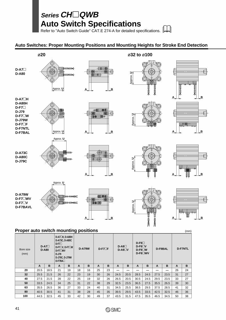
41
Auto Switches: Proper Mounting Positions and Mounting Heights for Stroke End Detection
ø20
D-A7HD-A80HD-F7D-J79D-F7WD-J79WD-F7FD-F7NTLD-F7BAL
D-A73CD-A80CD-J79C
D-A79WD-F7WVD-F7VD-F7BAVL
ø32 to ø100
Approx. U
Approx. U
BAA
ppro
x. U
App
rox.
UA
ppro
x. U
A B
A B
A B
BA
BA
Approx. U
D-A7D-A80
App
rox.
U
A B
BAApprox. US
MC
SM
C
SM
CS
MC
20
32
40
50
63
80
100
D-A7D-A80
D-A9D-A9V
D-F9D-F9VD-F9WD-F9WV
D-F7F D-F9BAL
A
20.5
25.5
27.5
33.5
35.5
40.5
44.5
B
18.5
21.5
21.5
24.5
26.5
30.5
32.5
A
21
26
28
34
36
41
45
B
19
22
22
25
27
31
33
A
18
23
25
31
33
38
42
B
16
19
19
22
24
28
30
A
25
30
32
38
40
45
49
B
23
26
26
29
31
35
37
A
—
24.5
26.5
32.5
34.5
39.5
43.5
B
—
20.5
20.5
23.5
25.5
29.5
31.5
A
—
28.5
30.5
36.5
38.5
43.5
47.5
B
—
24.5
24.5
27.5
29.5
33.5
35.5
A
—
27.5
29.5
35.5
37.5
42.5
46.5
B
—
23.5
23.5
26.5
28.5
32.5
34.5
A
26
31
33
39
41
46
50
B
24
27
27
30
32
36
38
D-A79W D-F7NTL
Proper auto switch mounting positions
Bore size
(mm)
(mm)
D-A7H, D-A80HD-A73C, D-A80CD-F7D-F7V, D-F7WD-F7WVD-J79D-J79C, D-J79WD-F7BA
Auto Switch SpecificationsRefer to "Auto Switch Guide" CAT.E 274-A for detailed specifications.
Series CHQWB

Auto switch mounting heights
20
32
40
50
63
80
100
D-A7D-A80
D-F9VD-F9WV D-F9BAL
D-A7HD-A80HD-J79D-J79WD-F7D-F7FD-F7NTLD-F7BALD-F7W
D-A73CD-A80CD-F7WV
U
24.5
31.5
35
41
47.5
57.5
67.5
U
25.5
32.5
36
42
48.5
58.5
68.5
U
31.5
38.5
42
48
54.5
64.5
74.5
U
28
35
38.5
44.5
51
61
71
U
—
27
30.5
36.5
40
50
60
U
—
29
32.5
38.5
42
52
62
U
—
26.5
30
36
39.5
49.5
59.5
U
31
38
41.5
47.5
54
64
74
U
27
34
37.5
43.5
50
60
70
D-J79C D-A79W D-A9VD-F7VD-F7BAVL
Bore size
(mm)
(mm)
ø32 to ø100
D-A9D-F9D-F9W
D-A9VD-F9VD-F9WV
D-F9BAL
A
BApprox. U
A
BApprox. U
A
B
42
Compact Hydraulic CylinderDouble Acting/Double Rod: 3.5MPa Series CHQWB

Auto Switch Mounting
ø20 ø32 to ø100
Auto switch mounting screw(M3 x 0.5 x 8l)
Square nut
Auto switch mounting screw(M3 x 0.5 x 10l)
Auto switch spacer
Auto switch mounting nut
Set screw
Mount auto switches in accordance with the procedures shown in the figures below.
43
Series CHQWB

44

2 pcs.1 pc.
"n" pcs.
NilSn
Number of auto switches
Without auto switchNilAuto switch typeBore size
With auto switch (built-in magnet)
Cylinder stroke (mm) Refer to the standard stroke table on page 46.
CHM 25 100
CHDM 25 100 C73
L
LWith Auto Switch
20253240
20mm25mm32mm40mm
Mounting typesBLFGC
Basic typeAxial foot typeFront flange typeRear flange typeSingle clevis type
Applicable Auto Switches:
Type Electricalentry
Connector
Connector
Indi
cato
rlig
ht
3-wire (NPN equiv.)
Load voltage
——
ACDC
Lead wire length (m)∗
0.5 (Nil)
3 (L)
5 (Z)
None (N)
———
——————
IC circuit
—
Applicableload
100V or less
—24V or less
—
200V or less
5V
Yes
Yes
Yes
Diagnostic indication(2-color display)
Diagnostic indication(2-color display)
With diagnostic output(2-color display)
Latch type with diagnosticoutput (2-color display)
With timer
Water resistant(2-color display)
YesNoYesNo
2-wire
2-wire
2-wire
2-wire
IC circuit
—IC circuit
———
—
—
—
—
—
Ree
d s
witc
hS
olid
sta
te s
witc
h
C76B53B54B64C73C80
C73CC80C
H7LF
—No
—
—
RelayPLC
RelayPLC
RelayPLC
PLC
PLC
12V
24V
—
24V
Grommet
Grommet
Grommet
DIN terminal
Terminalconduit
Terminalconduit
Grommet
Wiring(output)
Special functionAuto
switchtype
—
100V
100V, 200V
—
IC circuit
—
3-wire (NPN)3-wire (PNP)
3-wire (NPN)
3-wire (NPN)3-wire (PNP)
3-wire (NPN)
4-wire (NPN)
5V, 12V
12V5V, 12V
12V
5V, 12V
12V
5V, 12V
12V
12V
5V, 12V
5V, 12V
12V
—
—
A33A34A44
B59W
H7A1H7A2H7BH7CG39K39
H7NWH7PWH7BW
H7BA
G5NT
H7NF
———
——
—
—
———
——
———
—
——
—
——————
—
—
—
IC circuit
IC circuit
IC circuit
—
Refer to "Auto Switch Guide" CAT. E274-A for further details on each auto switch.Refer to pages 117 and 118 for auto switch circuit diagrams.
How to Order
∗ Select applicable auto switch models from the table below.
Round Type Low Pressure Hydraulic Cylinder
Series CHMø20, ø25, ø32, ø403.5MPa
45
Notes) • Solid state switches marked "" are produced upon receipt of order.• Do not indicate lead wire length symbol N (none) for types D-A3,
D-A44, D-G-39 or D-K39.
∗ Lead wire length symbols: 0.5m ....... Nil (Example) C73C3m .......... L (Example) C73CL5m .......... Z (Example) C73CZNone ...... N (Example) C73CN

Action
FluidNominal pressure
Proof pressure
Maximum allowable pressure
Minimum operating pressure
Ambient and fluid temperature
Piston speed
Cushion
Rod end thread
Thread tolerance
Double acting/Single rod
Hydraulic fluid
3.5MPa
5.0MPa
3.5MPa
0.3MPa
Without auto switch: –10° to 80°CWith auto switch: –10° to 60°C
8 to 300mm/s
None
Male thread
JIS class 2
to 250mm250 to 800mm
Basic type, Axial foot typeRear flange type, Front flange type
Single clevis type
Bore size (mm)
20
25
32
40
Standard stroke (mm)
25 to 800
Specifications
Standard Strokes
Mounting bracket
Accessories
Hydraulic Fluid Compatibility
JIS symbol
• Light aluminum body
• Auto switch can be mounted.
Mounting type
Stroke length tolerance+1.0 0
+1.4 0
Stan
dard
Op
tion
al
Mounting nut
Knuckle bracket
Rod end nutClevis pinSingle knuckle joint
Double knuckle joint(with pin)
Basic type Foot type Rearflange type
Front flange type
Singleclevis type
(2 pcs.)
—
—
—
—
—
(2 pcs.)
(1 pc.)
(1 pc.) —
Auto Switch Mounting Bracket Part Nos. (Band & Screw included)
Bore size (mm) 20
∗ When ordering the axial foot type, order 2 pcs. for each cylinder.
Axial foot∗
Flange
CHM-L020
CHM-F020
CHM-L025
CHM-F025
CHM-L032
CHM-F032
CHM-L040
CHM-F040
25 32 40
Mounting Bracket Part Nos.
Bore size (mm)
Auto switch models
20
25
32
40
D-C7, D-C8D-H7
D-B5, D-B6D-G5, D-K5
D-A3, D-A4
BMA2-020
BMA2-025
BMA2-032
BMA2-040
BA-01
BA-02
BA-32
BA-04
BD1-01M
BD1-02M
BD1-02
BD1-04M
Refer to page 47 regarding minimum strokes for auto switch mounting.
Note) Refer to page 136 for definitions of terms related to pressure.
∗ Orders of the standard strokes above can be supplied with a minimum lead time.
Please consult with SMC regarding the manufacture of strokes other than the above.
46
Round Type Low Pressure Hydraulic Cylinder: 3.5MPa Series CHM
mm
mm
Hydraulic fluid Compatibility
Compatible
Compatible
Compatible
Not compatible
Not compatible
Standard mineral hydraulic fluid
W/O hydraulic fluid
O/W hydraulic fluid
Water/Glycol hydraulic fluid
Phosphate hydraulic fluid
[Stainless Steel Mounting Screw Kit]The following stainless steel mounting screw kit (including nuts) is available to meet special operating environment conditions. (Please note that auto switch mounting bands are not included and must be ordered separately.)
Stainless steel mounting screw kit: BBA3 for D-B5, D-B6, D-G5, and D-K5Stainless steel mounting screw kit: BBA4 for D-C7, D-C8, and D-H7
When the type D-H7BAL switch is shipped already mounted on a cylinder, the above stainless steel screws are used. When the same switch is ordered separately, BBA4 screw kit is automatically included with the switches.

Minimum Strokes for Auto Switch Mounting
Specific Product Precautions
Caution1. Since Series CHM does not have an
air release valve, release air from components other than the cylinder (e.g. from piping, etc.).
2. When operating a cylinder for the first time, be sure to release the air at low pressure. When the air release is complete, operate the cylinder at reduced pressure, then gradually increase it to the normal operating pressure. However, the piston speed at this time should be adjusted to the minimum speed.
1. When mounting with bracket mounting nuts, tighten them using the tightening torques in the table below as a guide.
2. When mounted with one side attached and one side free (basic type, flange type) and operating at high speed, the bending moment acts on the cylinder due to oscillation at the stroke end, which may cause cylinder damage. In this type of situation, install brackets to suppress the oscillation of the cylinder body, or reduce the piston speed enough so that the cylinder body does not oscillate at the stroke end.
Air Release
Bore size (mm)
20253240
Theoretical Output
Weights
Bore size (mm) 20 25 32 40(kg)
0.20
0.44
0.29
0.18
0.06
0.29
0.55
0.46
0.37
0.08
0.50
0.88
0.69
0.64
0.12
0.82
1.36
1.03
0.77
0.16
Bas
ic w
eig
ht
Basic type
Axial foot type
Flange type
Clevis type
Additional weight per 50mm
Caution
Mounting
Mounting nutthread
Mounting nutwidth across flats (mm)
Tighteningtorque(N⋅m)
M22 x 1.5
M24 x 1.5
M30 x 1.5
M33 x 1.5
45
60
85
110
26
32
38
41
Theoretical output (N) = Pressure (MPa) x Piston area (mm²)
Bore size(mm)
Piston area(mm²)
Rod size(mm)
20
25
32
40
10
12
16
18
OUT
IN
OUT
IN
OUT
IN
OUT
IN
314
235
490
377
804
603
1256
1002
1 1.5 2 2.5 3 3.5Operatingdirection
Operating pressure (MPa)
Unit (N)
314
235
490
377
804
603
1256
1002
471
352
735
565
1206
904
1884
1503
628
470
980
754
1608
1206
2512
2004
785
587
1225
942
2010
1507
3140
2505
942
705
1470
1131
2412
1809
3768
3006
1099
822
1715
1319
2814
2110
4396
3507
Calculation method
(Example) CHML20–100(Foot type ø20/100mm stroke)
Basic weight .......... 0.44kg
Additional weight ... 0.06/50mm
Cylinder stroke ...... 100mm0.44 + 0.06 x 100/50 = 0.56kg
Be sure to read before handling. Refer to pages 135 through 141 for safety instructions, hydraulic cylinder precautions and auto switch precautions.
47
(mm)
Auto switch model
No. of auto switches
D-C7D-C8
D-H7D-H7WD-H7BALD-H7NF
D-B5D-B6D-G5NTL
D-C73CD-C80CD-H7C
D-H7LF
D-B59W
D-A3D-G39D-K39D-A44
15 + 45 n – 22
(n = 2, 4, 6 …)
Differentsides
2 pcs. "n" pcs.
15
15
15
15
20
20
35
Same side Different sides
50
60
65
75
65
75
100
1 pc.
10
10
10
10
10
15
10
Same side
50 + 45 (n – 2)
60 + 45 (n – 2)
65 + 50 (n – 2)
75 + 55 (n – 2)
100 + 100 (n – 2)
n: Number of auto switches
15 + 50 n – 22
(n = 2, 4, 6 …)
20 + 50 n – 22
(n = 2, 4, 6 …)
15 + 50 n – 22
(n = 2, 4, 6 …)
20 + 50 n – 22
(n = 2, 4, 6 …)
35 + 30 (n – 2)
Series CHM
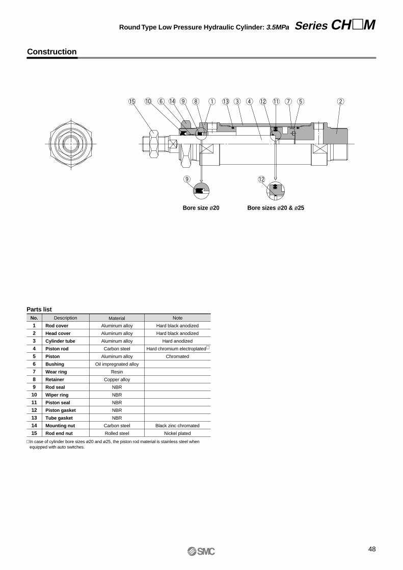
Construction
No.
1
2
3
4
5
6
7
8
9
10
11
12
13
14
15
Description Material Note
Parts list
Rod cover
Head cover
Cylinder tube
Piston rod
Piston
Bushing
Wear ring
Retainer
Rod seal
Wiper ring
Piston seal
Piston gasket
Tube gasket
Mounting nut
Rod end nut
Aluminum alloy
Aluminum alloy
Aluminum alloy
Carbon steel
Aluminum alloy
Oil impregnated alloy
Resin
Copper alloy
NBR
NBR
NBR
NBR
NBR
Carbon steel
Rolled steel
Hard black anodized
Hard black anodized
Hard anodized
Hard chromium electroplated∗
Chromated
Black zinc chromated
Nickel plated
Bore size ø20 Bore sizes ø20 & ø25
∗ In case of cylinder bore sizes ø20 and ø25, the piston rod material is stainless steel when equipped with auto switches.
48
Round Type Low Pressure Hydraulic Cylinder: 3.5MPa Series CHM
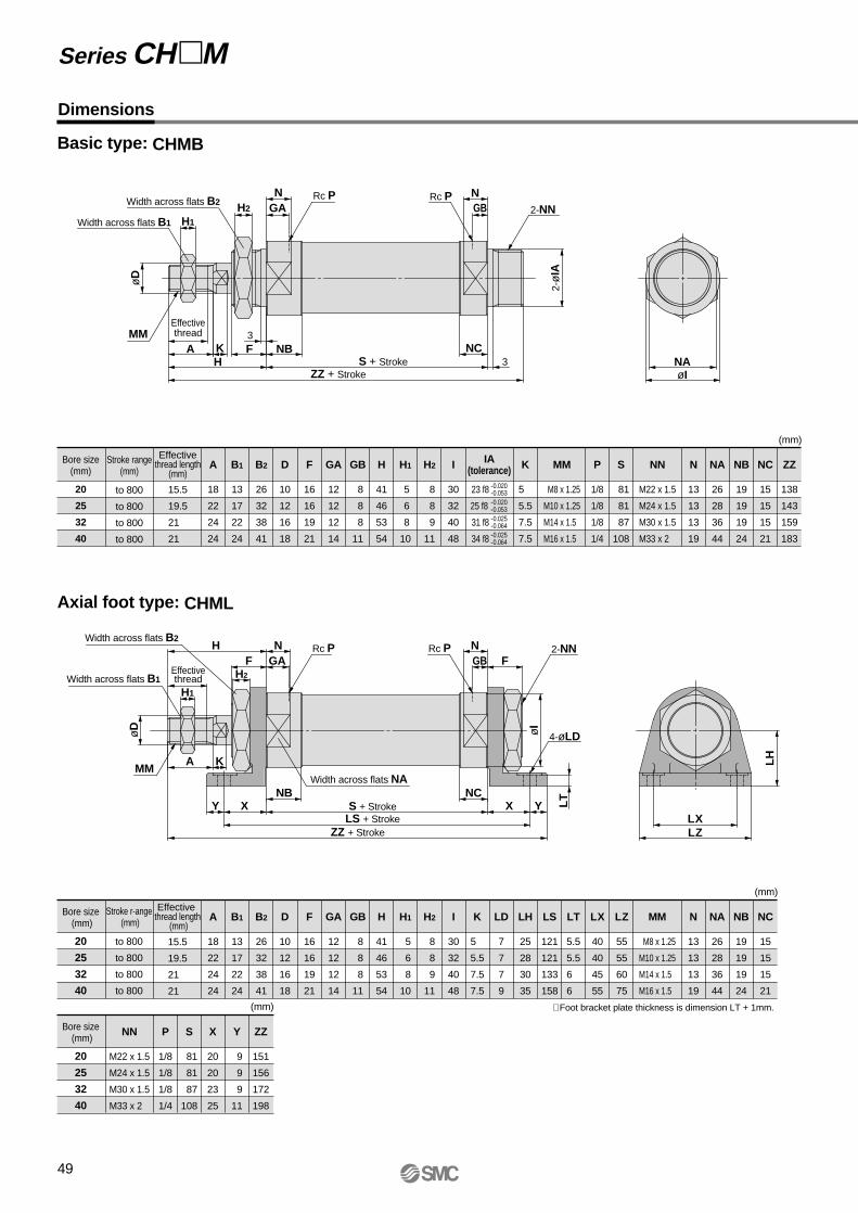
Basic type: CHMB
Axial foot type: CHML
Dimensions
49
Bore size(mm)
20
25
32
40
Stroke range(mm)
to 800
to 800
to 800
to 800
Effectivethread length
(mm)
15.5
19.5
21
21
A
18
22
24
24
B1
13
17
22
24
B2
26
32
38
41
D
10
12
16
18
F
16
16
19
21
GA
12
12
12
14
GB
8
8
8
11
H
41
46
53
54
H1
5
6
8
10
H2
8
8
9
11
I
30
32
40
48
K
5
5.5
7.5
7.5
P
1/8
1/8
1/8
1/4
S
81
81
87
108
N
13
13
13
19
NA
26
28
36
44
NB
19
19
19
24
NC
15
15
15
21
ZZ
138
143
159
183
MM
M8 x 1.25
M10 x 1.25
M14 x 1.5
M16 x 1.5
NN
M22 x 1.5
M24 x 1.5
M30 x 1.5
M33 x 2
IA(tolerance)
23 f8
25 f8
31 f8
34 f8
(mm)
Series CHM
-0.020-0.053-0.020-0.053-0.025-0.064-0.025-0.064
Bore size (mm)
20
25
32
40
Stroke r-ange (mm)
to 800
to 800
to 800
to 800
Effective thread length
(mm)
15.5
19.5
21
21
A
18
22
24
24
B1
13
17
22
24
B2
26
32
38
41
D
10
12
16
18
F
16
16
19
21
GA
12
12
12
14
GB
8
8
8
11
H
41
46
53
54
H1
5
6
8
10
I
30
32
40
48
K
5
5.5
7.5
7.5
H2
8
8
9
11
LH
25
28
30
35
LD
7
7
7
9
LS
121
121
133
158
LX
40
40
45
55
LT
5.5
5.5
6
6
LZ
55
55
60
75
NB
19
19
19
24
N
13
13
13
19
NA
26
28
36
44
NC
15
15
15
21
MM
M8 x 1.25
M10 x 1.25
M14 x 1.5
M16 x 1.5
(mm)
Bore size (mm)
20
25
32
40
Y
9
9
9
11
ZZ
151
156
172
198
NN
M22 x 1.5
M24 x 1.5
M30 x 1.5
M33 x 2
P
1/8
1/8
1/8
1/4
S
81
81
87
108
X
20
20
23
25
(mm) ∗ Foot bracket plate thickness is dimension LT + 1mm.
Width across flats B1 H1
H2Width across flats B2
NGA
Rc P NGB
Rc P2-NN
2-ø
IA
NAøI
øD
MMEffectivethread
A F NB NCKH S + Stroke
ZZ + Stroke
3
3
H NGAF
NGB F
Effectivethread H2
H1
øD
MMA K
Y XNB
YXLX
LH
LZ
NCWidth across flats NA
S + StrokeLS + Stroke
ZZ + Stroke
Rc P Rc P 2-NN
4-øLD
LT
øI
Width across flats B2
Width across flats B1

Front flange type: CHMF
Bore size(mm)
20
25
32
40
Stroke range(mm)
to 800
to 800
to 800
to 800
15.5
19.5
21
21
A
18
22
24
24
B1
13
17
22
24
B
38
44
50
60
B2
26
32
38
41
D
10
12
16
18
F
16
16
19
21
GA
12
12
12
14
GB
8
8
8
11
I
30
32
40
48
K
5
5.5
7.5
7.5
N
13
13
13
19
NA
26
28
36
44
FY
21
27
33
36
FZ
68
70
72
84
FD
7
7
7
9
FT
6
9
9
9
FX
51
53
55
66
H
41
46
53
54
H1
5
6
8
10
H2
8
8
9
11
MM
M8 x 1.25
M10 x 1.25
M14 x 1.5
M16 x 1.5
23 f8
25 f8
31 f8
34 f8
(mm)
-0.020-0.053-0.020-0.053-0.025-0.064-0.025-0.064
Bore size (mm)
20
25
32
40
P
1/8
1/8
1/8
1/4
ZZ
138
143
159
183
NB
19
19
19
24
NC
15
15
15
21
S
81
81
87
108
NN
M22 x 1.5
M24 x 1.5
M30 x 1.5
M33 x 2
(mm)
FX
FYB
FZ
4-øFD
øD
Width across flats B1
Width across flats B2
H1H2
NGA GB
Rc P NRc P2-NN
øI
øIA
MM Effectivethread
AH S + Stroke
ZZ + Stroke
K F NB Width across flats NA NCFT
3
IA(tolerance)
Effective thread length
(mm)
Round Type Low Pressure Hydraulic Cylinder: 3.5MPa Series CHM
50

Dimensions
Rear flange type: CHMG
Bore size (mm)
20
25
32
40
to 800
to 800
to 800
to 800
15.5
19.5
21
21
A
18
22
24
24
B1
13
17
22
24
B
38
44
50
60
B2
26
32
38
41
D
10
12
16
18
F
16
16
19
21
FD
7
7
7
9
FT
6
9
9
9
FX
51
53
55
66
GA
12
12
12
14
K
5
5.5
7.5
7.5
N
13
13
13
19
NA
26
28
36
44
H1
5
6
8
10
H2
8
8
9
11
H
41
46
53
54
FZ
68
70
72
84
FY
21
27
33
36
GB
8
8
8
11
I
30
32
40
48
MM
M8 x 1.25
M10 x 1.25
M14 x 1.5
M16 x 1.5
23 f8
25 f8
31 f8
34 f8
(mm)
-0.020-0.053-0.020-0.053-0.025-0.064-0.025-0.064
Bore size (mm)
20
25
32
40
P
1/8
1/8
1/8
1/4
S
81
81
87
108
ZZ
138
143
159
183
NB
19
19
19
24
NC
15
15
15
21
NN
M22 x 1.5
M24 x 1.5
M30 x 1.5
M33 x 2
(mm)
FX
FYB
FZ
4-øFDWidth across flats B2H2GB
NRc PGAN Rc P2-NN
H1Width across flats B1
øD
øIAøI
MMEffectivethread
A FKH
NBS + Stroke
ZZ + StrokeFT
NC3 Width across flats NA
Single clevis type: CHMC
Bore size (mm)
20
25
32
40
to 800
to 800
to 800
to 800
15.5
19.5
21
21
A
18
22
24
24
B1
13
17
22
24
CD
10
10
12
12
CX
16
16
16
24
D
10
12
16
18
F
16
16
19
21
GA
12
12
12
14
H1
5
6
8
10
I
30
32
40
48
H
41
46
53
54
GB
8
8
8
11
NB
19
19
19
24
NC
15
15
15
21
P
1/8
1/8
1/8
1/4
NN
M22 x 1.5
M24 x 1.5
M30 x 1.5
M33 x 2
RR
13.5
14.5
18.5
22.5
K
5
5.5
7.5
7.5
N
13
13
13
19
NA
26
28
36
44
Z
136
142
160
182
ZZ
149.5
156.5
178.5
204.5
U
14
15
20
20
S
81
81
87
108
MM
M8 x 1.25
M10 x 1.25
M14 x 1.5
M16 x 1.5
23 f8
25 f8
31 f8
34 f8
(mm)
-0.020-0.053-0.020-0.053-0.025-0.064-0.025-0.064
NGA
Rc PGB
Rc PøCD +0.109
0
–0.1–0.2
RRCX
øIS + StrokeH
AMM
K F NBU
NC
Effectivethread 3 Width across flats NA
Z + StrokeZZ + Stroke
H1NN
Width across flats B1
øD
øIA
Stroke range(mm)
Effective thread length
(mm)IA
(tolerance)
Stroke range(mm)
Effectivethread length
(mm)IA
(tolerance)
51
Series CHM

52
Round Type Low Pressure Hydraulic Cylinder: 3.5MPa Series CHM
Accessories (Standard)
Rod end nut Mounting nut
H
MM
U1 U1A1
L1 L1
L tap4-J counter bore
A1
øE
1 øE
1
NX
ø8.
6
ø9d
9-0
.040
-0.0
76
ø12
d9-0
.050
-0.0
93
NZ
NX
øE
1
øE
1
øC
NX
NZ
EF
G
H
IA B
D+0
.2+0
.1
B
d
D
H B
D CC
30° 30°
Part no. d H B C DApplicable
bore size (mm)
NT-02NT-03NT-04AC-NI-50
M8 x 1.25M10 x 1.25M14 x 1.5 M16 x 1.5
20253240
56810
13172224
15.019.625.427.7
12.516.521.023
Material: Carbon steel
Part no. d H B C DApplicablebore size (mm)
SO-02SO-03SO-04SO-05
M22 x 1.5M24 x 1.5M30 x 1.5M33 x 2.0
20253240
8 8 911
26323841
30 36.943.947.3
26323841
Material: Carbon steel
d
Accessory Brackets (Optional)
I-type single knuckle joint Bracket
Part no. A1 L1 R1 U1 NDH10U(H8)
E1 MM NXApplicablebore size
(mm)
Applicablebore size
(mm)
I-02I-03I-04IA-04
M8 x 1.25M10 x 1.25
M14 x 1.5 M16 x 1.5
20253240
101015.515.5
16182222
20202424
36385555
14142020
99
1212
99
1616
Part no. HG I J K L
AD-FI-20AD-FI-25AD-FI-32AD-FI-40
20253240
6.56.51010
5.55.599
M R
5.55.5710
A B C D E F
46465664
60608088
22223030
16161624
10101212
30303644
7779
28304043
10101313
10101212
12121216
M4M4M5M5
Material: Cast iron
+0.058 0
-0.1-0.2-0.1-0.2-0.1-0.3-0.1-0.3
+0.058 0+0.070 0+0.070 0
+0.027 0+0.027 0+0.027 0+0.027 0
Size Tolerance
ø20: I-02ø25: I-03Material: Rolled steel
ø32: I-04ø40: IA-04Material: Cast iron
øNDH10
øNDH10RR1
RR1MM
NX
øNDH10 øNDH10
RR1
RR1
45°
4-øK
M C
R øU
Y-type double knuckle joint Bracket pin
Part no. A1 L1 R1 U1 NDH10C (f8)
E1 MM NX NZApplicablebore size
(mm)
Applicablebore size (mm) Cotter pin
Y-02
Y-03
Y-04AY-04B
M8 x 1.25
M10 x 1.25
M14 x 1.5 M16 x 1.5
20
25
3240
5
5
1313
16
18
2222
20
20
2424
36
38
5555
14
14
2525
18
18
3838
Applicablepin no.
CDP-1
CDP-1
CDP-3CDP-3
Snap ring/Cotter pin sizeC type,
ø9 for shaftC type,
ø9 for shaftø3 x 18lø3 x 18l
9
9
1212
9
9
1616
Part no.
AD-EI-20AD-EI-25AD-EI-32AD-EI-40
20253240
A B D
45.545.55260
35.535.54250
3.23.244
10101212
Material: Carbon steel
+0.058 0
+0.2+0.1
+0.2+0.1
+0.3+0.1+0.3+0.1
+0.058 0
+0.070 0+0.070 0
-0.013-0.035-0.013-0.035-0.016-0.043-0.016-0.043
Size Tolerance
ø20: Y-02ø25: Y-03Material: Rolled steel
ø32: Y-04Aø40: Y-04BMaterial: Cast iron
MM
A1 A1 U1
L1
AB
2-øD drill through
L1
25
19.2 1.75 41.7
49.7
41.75
U1
Clevis pin & Knuckle pinBore size: ø20 & ø25Part no.: CDP-1Material: Carbon steel
Bore size: ø32 & ø40Part no.: CDP-3Material: Carbon steel
ø3.2 x 16l
ø4 x 20l
C1Chamfer
C1Chamfer
1.15 1.15
2-ø3drill through
Snap ring: C type, ø9 size for shaft Cotter pin: ø3 x 18l

Auto Switches: Proper Mounting Positions and Mounting Heights for Stroke End Detection
D-C7, D-C8 D-H7, D-H7W, D-H7F, D-H7BAL
D-G5, D-K5, D-G5W, D-G5BA, D-K59W, D-G59F, D-G5NT D-A4
D-C73C, D-C80C D-H7C
D-B5, D-B6, D-B59W D-A3, D-G3, D-K3
Approx. HS
16
Approx. HS
16
Approx. HS
24.5
Approx. HS
24.5
20
25
32
40
D-C7D-C8D-C73CD-C80C
D-B5D-B6
D-H7D-H7CD-H7WD-H7BAL
D-H7F D-B59W
D-G39D-K39D-A33, D-A34D-A44
D-G5NTL
A
15
15.5
19.5
24
B
13
12.5
14.5
20
A
9
9.5
13.5
18
B
7
6.5
8.5
14
A
14
14.5
18.5
23
B
12
11.5
13.5
19
A
10.5
11
15
19.5
B
8.5
8
10
15.5
A
12
12.5
16
21
B
10
9.5
11.5
17
A
8.5
9
13
17.5
B
6.5
6
8
13.5
A
14
14.5
18.5
23
B
12
11.5
13.5
19
Proper auto switch mounting positions
Auto switch mounting heights
Bore size
(mm)
20
25
32
40
Bore size
(mm)
D-B5/B6D-B59WD-G5NTLD-H7C
D-C7D-C8D-H7D-H7WD-H7FD-H7BAL
D-C73CD-C80C
D-G39D-K39D-A33D-A34
D-A44
HS
24.5
27
30.5
35
HS
27.5
30
33.5
38
HS
27
29.5
33
37.5
HS
62
64.5
68
72.5
HS
72
74.5
78
82.5
(mm)
(mm)
SM
C
SM
C
SM
C SM
C
SM
C
SM
C
8.5 Approx. HS 8.5
A 26 BAuto switch
Auto switch
Auto switch
A B36.7
12
A B33
A 33
6.5
Auto switch
12
BAuto switch
16
Approx. HS
Approx. HS
Approx. HS
16
A B29(36)
Auto switch
A B38.2 Auto switch
8.5
36
36
49.5A B
49A B
G 1/2 (applicable cable O.D. ø6.8 to 11.5)
Auto switch
G 1/2(applicable cable O.D. ø6.8 to 9.6)
∗ Values inside ( ) are for D-H7LF.
53
Series CHMAuto Switch SpecificationsRefer to "Auto Switch Guide" CAT.E 274-A for detailed specifications.

54

How to Order
55
JIS Standard Hydraulic CylinderDouble Acting/Single Rod
Series CH2E/CH2F/CH2G/CH2Hø32, ø40, ø50, ø63, ø80, ø100
CH2 H BB 50 100
CH D2 H BB 50 100 A53With Auto Switch
Bore size 32 40 50 63 80100
32mm 40mm 50mm 63mm 80mm100mm
Applicable Auto Switches:
Type Electricalentry
Terminalconduit
Terminalconduit
Indi
cato
rlig
ht
3-wire NPN (equiv.)
Load voltage
——
100V, 200V—
200V or less—
100V, 200V
—
ACDC
Lead wire length∗
0.5(Nil)
3(L)
5(Z)
———————
—————
—————————
IC circuit
IC circuit
IC circuit
IC circuit
IC circuit
IC circuit
Applicableload
5V12V12V
5V, 12V5V, 12V
12V
—
5V, 12V
—12V
5V, 12V12V
5V, 12V
12V
5V, 12V
A56A53A54A67A64———
A59WF59F5PJ51J59——
F59WF5PWJ59WF5BAF5NTF59F
—B53B54—
B64 A33∗∗ A34∗∗ A44∗∗B59WG59G5P—
K59 G39∗∗ K39∗∗G59WG5PWK59WG5BAG5NTG59F
—Yes
Yes
Yes
Diagnostic indication (2-color display)
Diagnostic indication(2-color display)
Water resistant (2-color display)With timer
With diagnostic output (2-color display)
3-wire (NPN)3-wire (PNP)
2-wire
3-wire (NPN)2-wire
3-wire (NPN)3-wire (PNP)
2-wire
3-wire (NPN)4-wire (NPN)
2-wire
Ree
d s
witc
hS
olid
sta
te s
witc
h
—
—
—
—
—
No
—
—
∗ Lead wire length symbols: 0.5m ........ Nil (Example) A533m .......... L A53L5m........... Z A53Z
—PLC
Relay, PLCPLC
Relay, PLC
PLC
RelayPLC
RelayPLC
24V
24V
24V
Grommet
Grommet
Grommet
DIN terminal
Grommet
Wiring(output)Special function
Auto switch typeTie-rod mount
Bandmount
—
—
—
Refer to pages 115 through 119 for auto switch specifications.
With auto switch(built-in magnet)
Tube materialAluminum alloyStainless steelStainless steel
Nominal pressure3.5MPa7MPa14MPa
SymbolEFH
Series type
Tube materialAluminum alloyStainless steel
SteelStainless steel
Nominal pressure3.5MPa7MPa14MPa14MPa
SymbolEFGH
Series type
Basic typeTransaxial foot typeAxial foot typeFront rectangular flange typeRear rectangular flange typeFront rectangular flange typeRear rectangular flange typeFront square flange typeRear square flange typeSingle clevis typeDouble clevis typeCenter trunnion type
BLALBFAFBFYFZFCFDCACBTC
Mounting types
2 pcs. 1 pc.3 pcs.
"n" pcs.
NilS3n
NilANilJKNilNRH
Number of auto switches
Rod size series BC
B-series rod sizeC-series rod size
For3.5 & 7MPa
For 14 MPa
Cylinder stroke (mm)Refer to the standard strokes table on page 56. Refer to page 58 for minimum strokes with auto switch.
Part nos. for cylinderswith built-in magnets
Without auto switchNil
Auto switch type
Cylinder optionsPort and cushion valve positions
∗ ø32 is for B-series rod size only.
∗ Indicate in alphabetical order.
∗ Refer to page 56.
Rod boot
Rod end nutWithout rod end nutWith rod end nutWithout rod bootNylon tarpaulinNeoprene clothWith double-side cushionWithout cushionWith front cushionWith rear cushion
Cushion
100V, 200V
In the case of cylinders with built-in magnets but no auto switches, do not indicate any auto switch type symbol.(Example) CHD2HLA50-100
3.5MPa7 MPa
14 MPa
∗ Select applicable auto switches from the table below.
∗∗ Not applicable to ø32.Notes) • The standard lead wire length is 0.5m. However, the standard length for G5NTL, G5BAL, F5NTL and F5BAL is 3m.
• Solid state switches marked "" are produced upon receipt of prder.

Note) Refer to page 136 for definitions of terms related to pressure.
56
Made to
Order
Page 75
JIS symbol
B
(Basic Type)
LA, LB
(Foot type)
FA, FB, FC, FD, FY, FZ(Flange type)
CA, CB(Single clevis type)
TC(Center trunnion type)
Port and Cushion Valve Positions
Mounting type
Position
Symbol Nil A C D E F G H
Port: TopCushion valve: Right
Port: RightCushion valve: Bottom
: Piping port : Cushion valve
Port: LeftCushion valve: Top
Port: TopCushion valve: Left
Port: TopCushion valve: Bottom
Port: RightCushion valve: Top
Port: RightCushion valve: Left
Port: LeftCushion valve: Right
Auto Switch Mounting Bracket Part Nos.
32
40
50
63
80
100
Standard Strokes
Standard strokes (mm) Long stroke (mm)
25 to 800
25 to 800
25 to 800
25 to 800
25 to 1000
25 to 1000
1800 (1401 or more with tie-rod reinforcing ring) Note 1)
1800 (1401 or more with tie-rod reinforcing ring) Note 1)
1800 (1401 or more with tie-rod reinforcing ring) Note 1)
1800 (1501 or more with tie-rod reinforcing ring) Note 2)
1800
1800
Cylinderbore size
(mm)
∗ Refer to the stroke selection Table in Technical Data 2, starting with page123, to determine stroke limitationdepending on the type of mounting brackets that will be used. Then make yur selection. Long stroke ranges also differ depending on the type of mounting brackets.
Note 1) The long stroke range for Series CH2E, CH2F, and CH2H with flange and clevis type mounting brackets as well as Series CHG is up to 1400mm.
Note 2) The long stroke range for Series CH2E, CH2F, and CH2H with flange and clevis type mounting brackets as well as Series CHG is up to 1500mm.
Model
Tube material
Nominal pressure
Bore size
Auto switch mounting
Models
CH2E
Aluminum alloy
3.5MPa
Applicable
CH2F
Stainless steel
7MPa
Applicable
CH2G
Steel
14MPa
—
CH2H
Stainless steel
14MPa
Applicable
32, 40, 50, 63, 80, 100mm
Model
Action
Fluid
Nominal pressure
Piston speed
Cushion
Thread tolerance
Specifications
CH2E
Maximumallowable pressure
Minimum operating pressure
Ambient and fluid temperature
Proof pressure
CH2F CH2G CH2H
Double acting/Single rod
Hydraulic fluid
3.5MPa 7MPa 14MPa
Rear: 9MPaFront: B-rod 13.5MPa
: C-rod 11MPa
Rear: 18MPaFront: B-rod 18MPa
: C-rod 14MPa3.5MPa
5.0MPa 10.5MPa 21MPa
When rear side is pressurized: 0.15MPaWhen front side is pressurized: 0.2MPa
Without auto switch: –10° to 80°CWith auto switch: –10° to 60°C
8 to 300mm/s
Cushion seal type
JIS class 2
Stroke length tolerance
JIS Standard Hydraulic Cylinder
Double Acting/Single Rod Series CH2E/CH2F/CH2G/CH2H
to 100mm mm, 101 to 250mm mm, 251 to 630mm mm
631 to 1000mm mm, 1001 to 1800mm mm
+0.8 0
+1.25 0
+1.0 0
+1.4 0
+1.8 0
∗ The cylinder's exterior dimensions represented here are as seen from the rod end of the cylinder.
CH2E
CH2F
CH2H
D-A3, D-A4D-G3, D-K3
D-B5, D-B6D-G5, D-K5
D-A5, D-A6D-F5, D-J5
3240506380
1003240506380
1003240506380
100
–BD1-04MBD1-05MBD1-06MBD1-08MBD1-10M
–BDS-04MBDS-05MBDS-06MBDS-08MBDS-10M
–BD1-04MBD1-05MBD1-06MBH1-080BH1-100
BA-32BA-04BA-05BA-06BA-08BA-10
BAF-32BAF-04BAF-05BAF-06BAF-08BAF-10
BGS1-032BH2-040BH2-050
BA-06BH2-080BH2-100
BT-06BT-06BT-06BT-08BT-16BT-18BT-06BT-06BT-06BT-08BT-16BT-18BT-06BT-06BT-06BT-08BT-16BT-18
ModelBore size
(mm)
Auto switch model

WeightsRod Sizes
B-series
C-series
40
22.4
18
50
28
22.4
63
35.5
28
80
45
35.5
100
56
45
Rod sizeseries∗
Bore size(mm)
(mm)
Accessories (Optional)
∗ Based on JIS B8367.
∗ Consult with SMC.
(Front and rear sides)
Cushion Strokes
Bore size (mm)
Effective cushion stroke
(mm)
40
16
50
17
63
16
80
20
100
23
Single knuckle, Double knuckle, Lock nut,
Knuckle pin, Rod boot (Nylon tarpulin,
Neoprene cloth) Note)
Note) Maximum operating temperature:Nylon tarpaulin (60°C), Neoprene cloth (110°C)
Series CH2E/CH2F/CH2G/CH2H
57
Water Resistant Hydraulic Cylinder
SpecificationsActionCylinder bore size (mm)CushionAuto switch mounting
Double acting/Single rod32, 40, 50, 63, 80, 100
Cushion sealTie-rod mounting
CHD2F F5BALMounting Bore size Rod series Stroke Cylinders options
With auto switch (built-in magnet)
Water resistant solid stateswitch with 2-color display
R
Water resistant cylinderNBR Seal (nitrile rubber)
FKM Seal (fluoro rubber)
R
V
Port position
∗ Piston seals are NBR for both types R and V.
3240506380
100
Bore size (mm)
A
B-series rodA————
13.514.5
∗ Specifications other than those above are the same as double acting/single rod specifications.
∗ Other dimensions are the same as those for the double acting/single rod standard type.
Unit: kgStandard weight (0 stroke)
Basic
2.502.492.592.603.273.333.663.554.904.985.495.327.937.698.498.43
13.0012.8914.7714.2118.9719.3722.1721.81
——
3.12 3.13
——
4.36 4.25
——
6.98 6.81
——
10.6410.58
——
18.3417.78
——
28.6228.26
3.353.343.443.454.364.424.754.646.866.947.457.28
10.8310.5911.3911.3317.5917.4819.3618.8026.4426.8429.6429.28
3.00 2.99
——
3.85 3.91
——
5.70 5.78
——
9.55 9.31
——
15.3615.25
——
22.3922.79
——
2.952.943.043.053.913.974.304.196.066.146.656.48
10.6710.4311.2311.1716.4016.2918.1717.6125.1525.5528.3527.99
0.040.040.060.050.080.080.100.100.090.100.140.140.170.170.200.200.240.260.340.300.410.460.490.54
2.94 2.93
——
3.86 3.92
——
5.98 6.06
——
9.54 9.30
——
15.6915.58
——
23.5723.97
——
3.063.053.153.164.124.184.514.406.076.156.666.49
10.6810.4411.2411.1816.4016.2918.1717.6125.1525.5528.3527.99
2.992.983.083.093.863.924.254.145.745.826.336.169.479.23
10.039.97
15.0214.9116.7916.2322.6223.0225.8225.46
3.493.483.583.594.574.634.964.857.507.588.097.9211.8111.5712.3712.3118.3518.2420.1219.5629.7830.1732.9832.62
Transaxialfoot
Singleclevis
Doubleclevis
Centertrunnion type
Rectangularflange
Rectangularflange (7MPa)
Squareflange
Additionalweight
(per 10mmstroke)
Mountingtype
ModelBoresize (mm)
32
40
50
63
80
100
CH2ECH2FCH2GCH2HCH2ECH2FCH2GCH2HCH2ECH2FCH2GCH2HCH2ECH2FCH2GCH2HCH2ECH2FCH2GCH2HCH2ECH2FCH2GCH2H
B LA FY, FZ FC, FD FA, FBCA CB TC LBAxialfoot
Standard weight (0 stroke)
Basic Transaxialfoot
Singleclevis
Doubleclevis
Centertrunnion type
Rectangularflange
Rectangularflange (7MPa)
Squareflange
Additionalweight
(per 10mmstroke)
Mountingtype
ModelBoresize (mm)
40
50
63
80
100
CH2ECH2FCH2GCH2HCH2ECH2FCH2GCH2HCH2ECH2FCH2GCH2HCH2ECH2FCH2GCH2HCH2ECH2FCH2GCH2H
B LA FY, FZ FC, FD FA, FBCA CB TC LBAxialfoot
3.193.253.583.474.744.825.335.167.627.398.198.1312.5612.4514.3213.7717.9118.3121.1120.75
4.494.554.884.777.347.427.937.7611.5011.2712.0712.0117.9117.8019.6719.1228.7229.1231.9231.56
——
4.28 4.17
——
6.82 6.65
——
10.3410.28
——
17.8917.34
——
27.5627.20
4.284.344.674.566.706.787.297.12
10.5210.2911.0911.0317.1517.0418.9118.3625.3825.7828.5828.22
3.833.894.224.115.905.986.496.32
10.3610.1310.9310.8715.9615.8517.7217.1724.0924.4927.2926.93
4.044.104.434.325.915.996.506.33
10.3710.1410.9410.8815.9615.8517.7217.1724.0924.4927.2926.93
3.783.844.174.065.585.666.176.009.168.939.739.67
14.5814.4716.3415.7921.5621.9624.7624.40
3.77 3.83
——
5.54 5.62
——
9.24 9.01
——
14.9214.81
——
21.3321.73
——
3.78 3.84
——
5.82 5.90
——
9.23 9.00
——
15.2515.14
——
22.5122.91
——
0.070.070.090.090.070.080.120.120.140.140.170.170.180.210.280.250.290.300.420.38
B-s
erie
s ro
dC
-ser
ies
rod
32
18
—
Hydraulic Fluid Compatibility
Hydraulic fluid Compatibility
Compatible
Compatible
Compatible
∗Not compatible
Standard mineral hydraulic fluid
W/O hydraulic fluid
O/W hydraulic fluid
Water/Glycol hydraulic fluid
Phosphate hydraulic fluid
32
16
∗ Stainless steel for the piston rod is a special order.

58
Theoretical OutputUnit: N
Bore size(mm)
Rod size(mm)
Operatingdirection
Piston area(mm²)
32
40
50
63
80
100
40
50
63
80
100
18
22.4
28
35.5
45
56
18
22.4
28
35.5
45
OUTIN
OUTIN
OUTIN
OUTIN
OUTIN
OUTIN
OUTIN
OUTIN
OUTIN
OUTIN
OUTIN
804 5501256 862196313473116212650243434785053881256100219631569311625005024403578506260
1 804 5501256 862196313473116212650243434785053881256100219631569311625005024403578506260
3.5 2813 1923 4396 3017 6869 471510905 744217584120202747518859 4396 3506 6869 549010905 875117584141212747521911
5 4019 2748 6280 4311 9813 6735155781063225120171723925026941 6280 5008 9813 7843155781250125120201743925031302
7 5627 3847 8792 603513738 9429218101488535168240415495037718 8792 70121373810980218101750235168282435495043823
10 8038 549512560 8621196251347131157212645024034344785005388212560100171962515686311572500250240403477850062604
14 11254 7693 17584 12070 27475 18859 43619 29769 70336 48081109900 75435 17584 14023 27475 21961 43619 35003 70336 56486109900 87645
Operating pressure (MPa)
B-s
erie
s ro
d
Minimum Strokes for Auto Switch MountingUnit: mm
Auto switch type No. of auto switchesMounting brackets other than
center trunnion Center trunnion type
2 pcs.
1 pc.
2 pcs.
1 pc.
2 pcs.
1 pc.
2 pcs.
1 pc.
2 pcs.
1 pc.
2 pcs.
1 pc.
2 pcs.
1 pc.
2 pcs.
1 pc.
2 pcs.
1 pc.
ø32
110
115
115
120
125
110
115
—
—
ø80
135
140
140
140
150
135
140
105
110
ø100
145
150
150
150
160
145
150
115
120
ø40
110
115
115
120
125
110
115
80
100
80
85
ø50
115
125
120
120
130
115
115
80
100
80
85
ø63
125
130
130
135
140
125
130
95
100
95
100
ø32
10
—
10
20
—
15
10
—
10
10
—
10
10
—
10
—
—
15
75
10
20
75
15
ø40 or larger
10
20
10
10
10
35
100
10
35
55
10
D-A5, D-A6
D-A59W
D-F5W, D-J5WD-F5BAL
D-F5, D-J5
D-F59FD-F5NTL
D-B5, D-B6D-G5, D-K59D-G5W, D-K59WD-G59FD-G5BAL, D-G5NTL
D-A44
D-B59W
D-A3D-G39, D-K39
Different sides
Same side
—
Different sides
Same side
—
Different sides
Same side
—
Different sides
Same side
—
Different sides
Same side
—
Different sides
Same side
—
Different sides
Same side
—
Different sides
Same side
—
Different sides
Same side
—
JIS Standard Hydraulic Cylinder
Double Acting/Single Rod Series CH2E/CH2F/CH2G/CH2HC
-ser
ies
rod

59
Construction
No.12345
6
7
891011
12
13
14151617181920212223242526272829303132
Description Material Note
Rod coverHead coverSeal holder (B-series rod)Seal holder (C-series rod)Retainer
Cylinder tube
Piston
Cushion ringCushion ring nutBushing (B-series rod) Bushing (C-series rod)
Piston rod (B-series rod)
Piston rod (C-series rod)
Tie-rodTie-rod nutCushion valveLock nutAir release valveCheck ballSnap ringBack-up ringScraper (B-series rod) Scraper (C-series rod) Rod seal (B-series rod) Rod seal (C-series rod) Piston sealCylinder tube gasketHolder gasketCushion valve sealCushion sealPiston gasketMagnet
Carbon steelCarbon steelCarbon steelCarbon steelCarbon steel
Metallic paintedMetallic paintedMetallic paintedMetallic paintedMetallic paintedHard anodized
Metallic painted
Hard chromiumelectroplated
Hard chromiumelectroplated
Parts list
Aluminum alloyStainless steelCarbon steel
Stainless steelAluminum alloyAluminum alloyStainless steelStainless steel
Replacement parts: Seal kits
Bore size (mm)Seal kit no.
Kit componentsB-series rod
CH2E32B-PS
CH2F32B-PS
CH2G32B-PS
CH2H32B-PS
CH2E40B-PS
CH2F40B-PS
CH2G40B-PS
CH2H40B-PS
CH2E50B-PS
CH2F50B-PS
CH2G50B-PS
CH2H50B-PS
CH2E63B-PS
CH2F63B-PS
CH2G63B-PS
CH2H63B-PS
CH2E80B-PS
CH2F80B-PS
CH2G80B-PS
CH2H80B-PS
CH2E100B-PS
CH2F100B-PS
CH2G100B-PS
CH2H100B-PS
C-series rod
CH2E40C-PS
CH2F40C-PS
CH2G40C-PS
CH2H40C-PS
CH2E50C-PS
CH2F50C-PS
CH2G50C-PS
CH2H50C-PS
CH2E63C-PS
CH2F63C-PS
CH2G63C-PS
CH2H63C-PS
CH2E80C-PS
CH2F80C-PS
CH2G80C-PS
CH2H80C-PS
CH2E100C-PS
CH2F100C-PS
CH2G100C-PS
CH2H100C-PS
32
40
50
63
80
100
Nos. 21 through 30from the chart at left
CH2ECH2FCH2GCH2HCH2ECH2FCH2GCH2H
Rolled steelRolled steelCopper alloyCopper alloy
Carbon steel
Carbon steel
Carbon steelCarbon steelAlloy steel
Carbon steelAlloy steel
Bearing steelCarbon tool steel
ResinNBRNBRNBRNBRNBRNBRNBRNBR—
NBR—
Series CH2G
Series CH2E, CH2F, CH2H
∗ Seal kits consist of items 21 through 30 and can be ordered by using the seal kit number for each bore size.
Series CH2E/CH2F/CH2G/CH2H

60
Dimensions
Basic type: CH2EB, CH2FB, CH2GB, CH2HB
Rod series
Bore size(mm)
Stroke range∗(mm)
1401 to 1800
1401 to 1800
1401 to 1800
1501 to 1800
—
—
28
28
33
43
—
—
RT RY
58
65
75
90
—
—
32
40
50
63
80
100
Long stroke (with tie-rod reinforcing ring)
Bore size(mm)
Stroke range(mm)
25 to 1400
25 to 1400
25 to 1400
25 to 1500
25 to 1800
25 to 1800
32
40
50
63
80
100
32
40
50
63
80
100
Bore size(mm)
B
58
65
76
90
110
135
C
38
45
52
63
80
102
F
16
12
15
15
17
19
GA
32
32
40
42
40
42
GB
15
15
19
19
22
22
M
11
11
11
14
16
18
NA
37
36
43
43
44
44
NB
31
30
35
35
44
44
P
3/8
3/8
1/2
1/2
3/4
3/4
S
141
141
155
163
184
192
R
39
42
46
52
65
75
T
11
11
13
15
18
20
—
52
52
55
65
80
52
52
55
65
80
100
ef
21.5
12
15
15
17
19
l
1/3.5stroke
With rod boot
B-series rod C-series rod
1/4stroke
Q
15
15
15
20
20
15
—
J
M10 x 1.25
M10 x 1.25
M10 x 1.25
M12 x 1.5
M16 x 1.5
M18 x 1.5
MM
M16 x 1.5
M20 x 1.5
M24 x 1.5
M30 x 1.5
M39 x 1.5
M48 x 1.5
A
25
30
35
45
60
75
MA
22
27
32
42
57
72
E K
7
9
11
13
15
16
G
14
19
24
30
41
50
H
55
60
65
80
95
115
ZZ
207
212
231
257
295
325
D
18
22.4
28
35.5
45
56
34
40
46
55
65
80
-0.025-0.064
-0.030-0.076
-0.036-0.090
-0.025-0.064
-0.030-0.076
MM—
M16 x 1.5
M20 x 1.5
M24 x 1.5
M30 x 1.5
M39 x 1.5
A—
25
30
35
45
60
MA—
22
27
32
42
57
—
36
40
46
55
65
—
K—
7
9
11
13
15
G—
14
19
24
30
41
H—
55
60
70
80
100
ZZ—
207
226
247
280
310
D—
18
22.4
28
35.5
45
E
(mm)
(mm)
H + Q + l
Air release
S + Stroke
ZZ + Stroke
Air release
ZZ + Q + l + Stroke
øe
øDøE
10 f
R
MM
GA
lC
B
2-Rc PTie-rod reinforcing ring(long stroke only)
Width across flats GMA
A K
H
F
GBRT J
NB
M
T NA
B-rod C-rodB-rod C-rod
JIS Standard Hydraulic Cylinder
Double Acting/Single Rod Series CH2E/CH2F/CH2G/CH2H
∗ Applicable to Series CH2E, CH2F and CH2H.Contact SMC regarding the Series CH2G with the above strokes.
RY

61
Dimensions
Transaxial foot type: CH2ELA, CH2FLA, CH2GLA, CH2HLA
Rod series
Bore size(mm)
Stroke range∗(mm)
1401 to 1800
1401 to 1800
1401 to 1800
1501 to 1800
—
—
28
28
33
43
—
—
RT
58
65
75
90
—
—
RY
32
40
50
63
80
100
Long stroke (with tie-rod reinforcing ring)
Bore size(mm)
Strokerange(mm)
25 to 1400
25 to 1400
25 to 1400
25 to 1500
25 to 1800
25 to 1800
32
40
50
63
80
100
32
40
50
63
80
100
Tolerance
Bore size(mm)
l
1/3.5stroke
With rod boot
B-series rod C-series rod
1/4stroke
J
M10 x 1.25
M10 x 1.25
M10 x 1.25
M12 x 1.5
M16 x 1.5
M18 x 1.5
MM
M16 x 1.5
M20 x 1.5
M24 x 1.5
M30 x 1.5
M39 x 1.5
M48 x 1.5
A
25
30
35
45
60
75
MA
22
27
32
42
57
72
K
7
9
11
13
15
16
G
14
19
24
30
41
50
H
66
71
78
95
113
135
ZZ
220
225
249
277
319
353
D
18
22.4
28
35.5
45
56
MM—
M16 x 1.5
M20 x 1.5
M24 x 1.5
M30 x 1.5
M39 x 1.5
A—
25
30
35
45
60
MA—
22
27
32
42
57
K—
7
9
11
13
15
G—
14
19
24
30
41
H—
66
73
85
98
120
ZZ—
220
244
267
304
338
D—
18
22.4
28
35.5
45
(mm)
±0.15±0.18
±0.20
±0.23±0.25
LH LX
B
58
65
76
90
110
135
C
38
45
52
63
80
102
GA
21
21
27
27
22
22
F
14
10
10
10
11
11
GB
15
15
19
19
22
22
S
130
130
142
148
166
172
LT
14
14
17
19
24
27
BB
109
118
145
165
190
230
Z
98
98
108
106
124
122
—
52
52
55
65
80
52
52
55
65
80
100
eCD
11
11
14
18
18
22
LH
35
37.5
45
50
60
71
LW
13
13
18
20
24
28
LX
88
95
115
132
155
190
X
29
29
35
41
45
53
SS
57
57
60
71
74
85
f
21.5
12
15
15
17
19
Q
15
15
15
20
20
15
Y
14
14
18
19
20
22
R
39
42
46
52
65
75
P
3/8
3/8
1/2
1/2
3/4
3/4
M
11
11
11
14
16
18
NA
37
36
43
43
44
44
NB
31
30
35
35
44
44
(mm)
H + Q + l
SS + Q + l + Stroke
S + Stroke
ZZ + StrokeZ + Stroke
ZZ + Q + l + Stroke
øe
øDøE
10
Air release
f
R
LH
LT
J
MM
H
GA
l C
2-Rc P
4-øCDMA
AK
SSX Y
RT
LWF NALW
GBNB
MX
Y
B
LX
BB
Bore size(mm)
32
40
50
63
80
100
E
34
40
46
55
65
80
-0.025-0.064
-0.030-0.076
E—
36
40
46
55
65
—
-0.025-0.064
-0.030-0.076-0.036
-0.090
—
B-rod C-rodB-rod C-rod
Series CH2E/CH2F/CH2G/CH2H
∗ Applicable to Series CH2E, CH2F and CH2H.Contact SMC regarding Series CH2G with the above strokes.
Width acrossflats G
RY

62
Axial foot type: CH2ELB, CH2FLB
Bore size (mm)
Stroke range∗(mm)
1401 to 1800
1401 to 1800
1401 to 1800
1501 to 1800
—
—
28
28
33
43
—
—
RT
58
65
75
90
—
—
RY
32
40
50
63
80
100
Long stroke(with tie-rod reinforcing ring)
H + Q + l
SS + Q + l + Stroke S + Stroke
SS + Stroke
ZZ + Stroke
Z + StrokeZZ + Q + l + Stroke
øD
øE
10
Air release
f
LH
LT
RJ
MMMAA
H
K GA
l
C 2-Rc P Tie-rod reinforcing ring(Long stroke only)
4-øCD
X1Y1
F
LW
GB
NB
M
X1 Y1NA
RT
T
B
LXBB
Air release
Rod series
Bore size(mm)
Strokerange(mm)
25 to 1400
25 to 1400
25 to 1400
25 to 1500
25 to 1800
25 to 1800
32
40
50
63
80
100
32
40
50
63
80
100
Tolerance
Bore size(mm)
l
1/3.5stroke
With rod boot
B-series rod C-series rod
1/4stroke
J
M10 x 1.25
M10 x 1.25
M10 x 1.25
M12 x 1.5
M16 x 1.5
M18 x 1.5
MM
M16 x 1.5
M20 x 1.5
M24 x 1.5
M30 x 1.5
M39 x 1.5
M48 x 1.5
A
25
30
35
45
60
75
MA
22
27
32
42
57
72
K
7
9
11
13
15
16
G
14
19
24
30
41
50
H
55
60
65
80
95
115
ZZ
241
246
270
303
349
385
D
18
22.4
28
35.5
45
56
MM—
M16 x 1.5
M20 x 1.5
M24 x 1.5
M30 x 1.5
M39 x 1.5
A—
25
30
35
45
60
MA—
22
27
32
42
57
K—
7
9
11
13
15
G—
14
19
24
30
41
H—
55
60
70
80
100
ZZ—
241
265
293
334
370
D—
18
22.4
28
35.5
45
(mm)
±0.15
±0.13
±0.15
±0.18±0.25
LH LX
B
58
65
76
90
110
135
C
38
45
52
63
80
102
GA
32
32
40
42
40
42
F
16
12
15
15
17
19
GB
15
15
19
19
22
22
S
141
141
155
163
184
192
LH
40
43
50
60
72
85
T
11
11
13
15
18
20
BB
62
69
85
98
118
150
Y1
13
13
15
18
20
23
Z
205
205
225
247
284
302
—
52
52
55
65
80
52
52
55
65
80
100
eCD
11
11
14
18
18
22
LT
8
8
8
10
12
12
LX
40
46
58
65
87
109
LW
30
33
37
45
50
55
SS
203
203
220
240
269
287
f
21.5
12
15
15
17
19
Q
15
15
15
20
20
15
X1
32
32
35
42
50
55
R
39
42
46
52
65
75
P
3/8
3/8
1/2
1/2
3/4
3/4
M
11
11
11
14
16
18
NA
37
36
43
43
44
44
NB
31
30
35
35
44
44
(mm)
Bore size(mm)
32
40
50
63
80
100
E
34
40
46
55
65
80
-0.025-0.064
-0.030-0.076
E—
36
40
46
55
65
—
-0.025-0.064
-0.030-0.076-0.036
-0.090
—
B-rod C-rodB-rod C-rod
JIS Standard Hydraulic Cylinder
Double Acting/Single Rod Series CH2E/CH2F/CH2G/CH2H
∗ Applicable to Series CH2E and CH2F.
RY
Width across flats G

63
Series CH2E/CH2F/CH2G/CH2H
Dimensions
Front rectangular flange type: CH2EFA, CH2FFA
H + Q + l
SS+ Q + l + Stroke
Airrelease
S + Stroke
ZZ + StrokeZZ + Q + l + Stroke
øe
øDøE
f
R
FY
BB
MM
MA
A SS
H
K
GA
l C
2-Rc P4-øFD GB
NB
M
J
NAFT
F
B
FX
FZ
Air release10
Rod series
Bore size(mm)
Strokerange(mm)
25 to 1400
25 to 1400
25 to 1400
25 to 1500
25 to 1800
25 to 1800
32
40
50
63
80
100
32
40
50
63
80
100
Tolerance
Bore size(mm)
le
1/3.5stroke
With rod boot
B-series rod C-series rod
1/4stroke
J
M10 x 1.25
M10 x 1.25
M10 x 1.25
M12 x 1.5
M16 x 1.5
M18 x 1.5
MM
M16 x 1.5
M20 x 1.5
M24 x 1.5
M30 x 1.5
M39 x 1.5
M48 x 1.5
A
25
30
35
45
60
75
MA
22
27
32
42
57
72
K
7
9
11
13
15
16
G
14
19
24
30
41
50
H
66
71
78
95
113
135
ZZ
207
212
231
257
295
325
D
18
22.4
28
35.5
45
56
MM—
M16 x 1.5
M20 x 1.5
M24 x 1.5
M30 x 1.5
M39 x 1.5
A—
25
30
35
45
60
MA—
22
27
32
42
57
K—
7
9
11
13
15
G—
14
19
24
30
41
H—
66
73
85
98
120
ZZ—
207
226
247
280
310
D—
18
22.4
28
35.5
45
(mm)
±0.2±0.18
±0.13
±0.15
±0.18
±0.2
±0.23±0.3
FT FY FX
B
58
65
76
90
110
135
C
38
45
52
63
80
102
GA
21
21
27
27
22
22
F
16
12
15
15
17
19
GB
15
15
19
19
22
22
S
130
130
142
148
166
172
FT
11
11
13
15
18
20
BB
62
69
85
98
118
150
—
52
52
55
65
80
52
52
55
65
80
100
FD
11
11
14
18
18
22
FX
88
95
115
132
155
190
FY
40
46
58
65
87
109
FZ
109
118
145
165
190
230
f
21.5
12
15
15
17
19
Q
15
15
15
20
20
15
SS
30
30
30
35
35
40
R
39
42
46
52
65
75
P
3/8
3/8
1/2
1/2
3/4
3/4
M
11
11
11
14
16
18
NA
37
36
43
43
44
44
NB
31
30
35
35
44
44
(mm)
Bore size(mm)
32
40
50
63
80
100
E
34
40
46
55
65
80
-0.025-0.064
-0.030-0.076
E—
36
40
46
55
65
—
-0.025-0.064
-0.030-0.076-0.036
-0.090
—
B-rod C-rodB-rod C-rod
Width across flats G

64
Front rectangular flange type: CH2GFY, CH2HFY
H + Q + l
SS + Q + l + Stroke
Airrelease
S + Stroke
ZZ + StrokeZZ + Q + l + Stroke
øe
øDøE
f
R
FY
BB
MM
MA
A SS
H
K
GA
l C
2-Rc P4-øFD GB
NB
M
J
NAFT
F
B
FX
FZ
Air release10
Rod series
Bore size(mm)
Strokerange(mm)
25 to 1400
25 to 1400
25 to 1400
25 to 1500
25 to 1800
25 to 1800
32
40
50
63
80
100
32
40
50
63
80
100
Tolerance
Bore size(mm)
l
1/3.5stroke
With rod boot
B-series rod C-series rod
1/4stroke
J
M10 x 1.25
M10 x 1.25
M10 x 1.25
M12 x 1.5
M16 x 1.5
M18 x 1.5
MM
M16 x 1.5
M20 x 1.5
M24 x 1.5
M30 x 1.5
M39 x 1.5
M48 x 1.5
A
25
30
35
45
60
75
MA
22
27
32
42
57
72
K
7
9
11
13
15
16
G
14
19
24
30
41
50
H
68
73
83
100
119
143
ZZ
209
214
236
262
301
333
D
18
22.4
28
35.5
45
56
MM—
M16 x 1.5
M20 x 1.5
M24 x 1.5
M30 x 1.5
M39 x 1.5
A—
25
30
35
45
60
MA—
22
27
32
42
57
K—
7
9
11
13
15
G—
14
19
24
30
41
H—
68
78
90
104
128
ZZ—
209
231
252
286
318
D—
18
22.4
28
35.5
45
(mm)
±0.2 ±0.13±0.18
±0.2
±0.23
±0.15
±0.18
±0.3
FT FX FY
B
58
65
76
90
110
135
C
38
45
52
63
80
102
GA
21
21
27
27
22
22
F
14
10
10
10
11
11
GB
15
15
19
19
22
22
S
130
130
142
148
166
172
FT
13
13
18
20
24
28
BB
62
69
85
98
118
150
—
52
52
55
65
80
52
52
55
65
80
100
eFD
11
11
14
18
18
22
FX
88
95
115
132
155
190
FY
40
46
58
65
87
109
FZ
109
118
145
165
190
230
f
21.5
12
15
15
17
19
Q
15
15
15
20
20
15
SS
30
30
30
35
35
40
R
39
42
46
52
65
75
P
3/8
3/8
1/2
1/2
3/4
3/4
M
11
11
11
14
16
18
NA
37
36
43
43
44
44
NB
31
30
35
35
44
44
(mm)
Bore size(mm)
32
40
50
63
80
100
E
34
40
46
55
65
80
-0.025-0.064
-0.030-0.076
E—
36
40
46
55
65
—
-0.025-0.064
-0.030-0.076-0.036
-0.090
—
B-rod C-rodB-rod C-rod
JIS Standard Hydraulic Cylinder
Double Acting/Single Rod Series CH2E/CH2F/CH2G/CH2H
Width across flats G

65
Series CH2E/CH2F/CH2G/CH2H
Dimensions
Rear rectangular flange type: CH2EFB, CH2FFB
H + Q + l
SS + Q + l + StrokeS + Stroke
SS + Stroke
ZZ + StrokeZZ + Q + l + Stroke
øe
øDøE
10 f
R
FY
BB
MM
MA
A
K F
GA
l C
2-Rc P 4-øFD
Air release
GB
NB
J
H
NAT FT
B
FX
FZ
Air release
Rod series
Bore size(mm)
Strokerange(mm)
25 to 1400
25 to 1400
25 to 1400
25 to 1500
25 to 1800
25 to 1800
32
40
50
63
80
100
32
40
50
63
80
100
Tolerance
Bore size(mm)
l
1/3.5stroke
With rod boot
B-series rod C-series rod
1/4stroke
J
M10 x 1.25
M10 x 1.25
M10 x 1.25
M12 x 1.5
M16 x 1.5
M18 x 1.5
MM
M16 x 1.5
M20 x 1.5
M24 x 1.5
M30 x 1.5
M39 x 1.5
M48 x 1.5
A
25
30
35
45
60
75
MA
22
27
32
42
57
72
K
7
9
11
13
15
16
G
14
19
24
30
41
50
H
55
60
65
80
95
115
ZZ
207
212
233
258
297
327
D
18
22.4
28
35.5
45
56
MM—
M16 x 1.5
M20 x 1.5
M24 x 1.5
M30 x 1.5
M39 x 1.5
A—
25
30
35
45
60
MA—
22
27
32
42
57
K—
7
9
11
13
15
G—
14
19
24
30
41
H—
55
60
70
80
100
ZZ—
207
228
248
282
312
D—
18
22.4
28
35.5
45
(mm)
±0.2±0.18
±0.13
±0.15
±0.18
±0.2
±0.23±0.3
FT FY FX
B
58
65
76
90
110
135
C
38
45
52
63
80
102
GA
32
32
40
42
40
42
F
16
12
15
15
17
19
GB
15
15
19
19
22
22
S
141
141
155
163
184
192
T
11
11
13
15
18
20
FT
11
11
13
15
18
20
BB
62
69
85
98
118
150
—
52
52
55
65
80
52
52
55
65
80
100
eFD
11
11
14
18
18
22
FX
88
95
115
132
155
190
FY
40
46
58
65
87
109
FZ
109
118
145
165
190
230
f
21.5
12
15
15
17
19
Q
15
15
15
20
20
15
SS
182
182
198
213
237
252
R
39
42
46
52
65
75
P
3/8
3/8
1/2
1/2
3/4
3/4
NA
37
36
43
43
44
44
NB
31
30
35
35
44
44
(mm)
Bore size(mm)
32
40
50
63
80
100
E
34
40
46
55
65
80
-0.025-0.064
-0.030-0.076
E—
36
40
46
55
65
—
-0.025-0.064
-0.030-0.076-0.036
-0.090
—
B-rod C-rodB-rod C-rod
Width acrossflats G

Rear rectangular flange type: CH2GFZ, CH2HFZ
66
H + Q + l
SS + Q + l + StrokeS + Stroke
SS + Stroke
ZZ + StrokeZZ + Q + l + Stroke
øe
øDøE
10 f
R
FY
BB
MM
MA
A
K F
GA
l C
2-Rc P 4-øFD
Air release
GB
NB
J
H
NAT FT
B
FX
FZ
Air release
Rod series
Bore size(mm)
Strokerange(mm)
25 to 1400
25 to 1400
25 to 1400
25 to 1500
25 to 1800
25 to 1800
32
40
50
63
80
100
32
40
50
63
80
100
l
1/3.5stroke
With rod boot
B-series rod C-series rod
1/4stroke
J
M10 x 1.25
M10 x 1.25
M10 x 1.25
M12 x 1.5
M16 x 1.5
M18 x 1.5
MM
M16 x 1.5
M20 x 1.5
M24 x 1.5
M30 x 1.5
M39 x 1.5
M48 x 1.5
A
25
30
35
45
60
75
MA
22
27
32
42
57
72
K
7
9
11
13
15
16
G
14
19
24
30
41
50
H
55
60
65
80
95
115
ZZ
209
214
238
263
303
335
D
18
22.4
28
35.5
45
56
MM—
M16 x 1.5
M20 x 1.5
M24 x 1.5
M30 x 1.5
M39 x 1.5
A—
25
30
35
45
60
MA—
22
27
32
42
57
K—
7
9
11
13
15
G—
14
19
24
30
41
H—
55
60
70
80
100
ZZ—
209
233
253
288
320
D—
18
22.4
28
35.5
45
(mm)
B
58
65
76
90
110
135
C
38
45
52
63
80
102
GA
32
32
40
42
40
42
F
16
12
15
15
17
19
GB
15
15
19
19
22
22
S
141
141
155
163
184
192
T
11
11
13
15
18
20
FT
13
13
18
20
24
28
BB
62
69
85
98
118
150
—
52
52
55
65
80
52
52
55
65
80
100
eFD
11
11
14
18
18
22
FX
88
95
115
132
155
190
FY
40
46
58
65
87
109
FZ
109
118
145
165
190
230
f
21.5
12
15
15
17
19
Q
15
15
15
20
20
15
SS
184
184
203
218
243
260
R
39
42
46
52
65
75
P
3/8
3/8
1/2
1/2
3/4
3/4
NA
37
36
43
43
44
44
NB
31
30
35
35
44
44
(mm)
Bore size(mm) E
34
40
46
55
65
80
-0.025-0.064
-0.030-0.076
E—
36
40
46
55
65
—
-0.025-0.064
-0.030-0.076-0.036
-0.090
—
B-rod C-rodB-rod C-rod
JIS Standard Hydraulic Cylinder
Double Acting/Single Rod Series CH2E/CH2F/CH2G/CH2H
Tolerance
Bore size(mm)
±0.2 ±0.13±0.18
±0.2
±0.23
±0.15
±0.18
±0.3
FT FX FY
32
40
50
63
80
100
Width acrossflats G

Series CH2E/CH2F/CH2G/CH2H
Dimensions
Front square flange type: CH2EFC, CH2FFC, CH2GFC, CH2HFC
67
H + Q + l
SS + Q + l + Stroke S + Stroke
ZZ + StrokeZZ + Q + l + Stroke
Airrelease
øe
øDøE
10 f
FY
FY
MM
MAA
K F
GA
l
C
2-Rc P
8-øFD
GB
NBM
J
H
NAFT
R
FX
FX
SSFZ
Air release
B
Rod series
Bore size(mm)
Strokerange(mm)
25 to 1400
25 to 1400
25 to 1400
25 to 1500
25 to 1800
25 to 1800
32
40
50
63
80
100
32
40
50
63
80
100
Tolerance
Bore size(mm)
l
1/3.5stroke
With rod boot
B-series rod C-series rod
1/4stroke
J
M10 x 1.25
M10 x 1.25
M10 x 1.25
M12 x 1.5
M16 x 1.5
M18 x 1.5
MM
M16 x 1.5
M20 x 1.5
M24 x 1.5
M30 x 1.5
M39 x 1.5
M48 x 1.5
A
25
30
35
45
60
75
MA
22
27
32
42
57
72
K
7
9
11
13
15
16
G
14
19
24
30
41
50
H
66
71
78
95
113
135
ZZ
207
212
231
257
295
325
D
18
22.4
28
35.5
45
56
MM—
M16 x 1.5
M20 x 1.5
M24 x 1.5
M30 x 1.5
M39 x 1.5
A—
25
30
35
45
60
MA—
22
27
32
42
57
K—
7
9
11
13
15
G—
14
19
24
30
41
H—
66
73
85
98
120
ZZ—
207
226
247
280
310
D—
18
22.4
28
35.5
45
(mm)
±0.2±0.18
±0.13
±0.15
±0.18
±0.2
±0.23±0.3
FT FX FY
B
58
65
76
90
110
135
C
38
45
52
63
80
102
GA
21
21
27
27
22
22
F
16
12
15
15
17
19
GB
15
15
19
19
22
22
S
130
130
142
148
166
172
FT
11
11
13
15
18
20
—
52
52
55
65
80
52
52
55
65
80
100
eFD
11
11
14
18
18
22
FX
40
46
58
65
87
109
FY
88
95
115
132
155
190
FZ
109
118
145
165
190
230
f
21.5
12
15
15
17
19
Q
15
15
15
20
20
15
SS
30
30
30
35
35
40
R
39
42
46
52
65
75
P
3/8
3/8
1/2
1/2
3/4
3/4
NA
37
36
43
43
44
44
M
11
11
11
14
16
18
NB
31
30
35
35
44
44
(mm)
Bore size(mm)
32
40
50
63
80
100
E
34
40
46
55
65
80
-0.025-0.064
-0.030-0.076
E—
36
40
46
55
65
—
-0.025-0.064
-0.030-0.076-0.036
-0.090
—
B-rod C-rodB-rod C-rod
Width acrossflats G
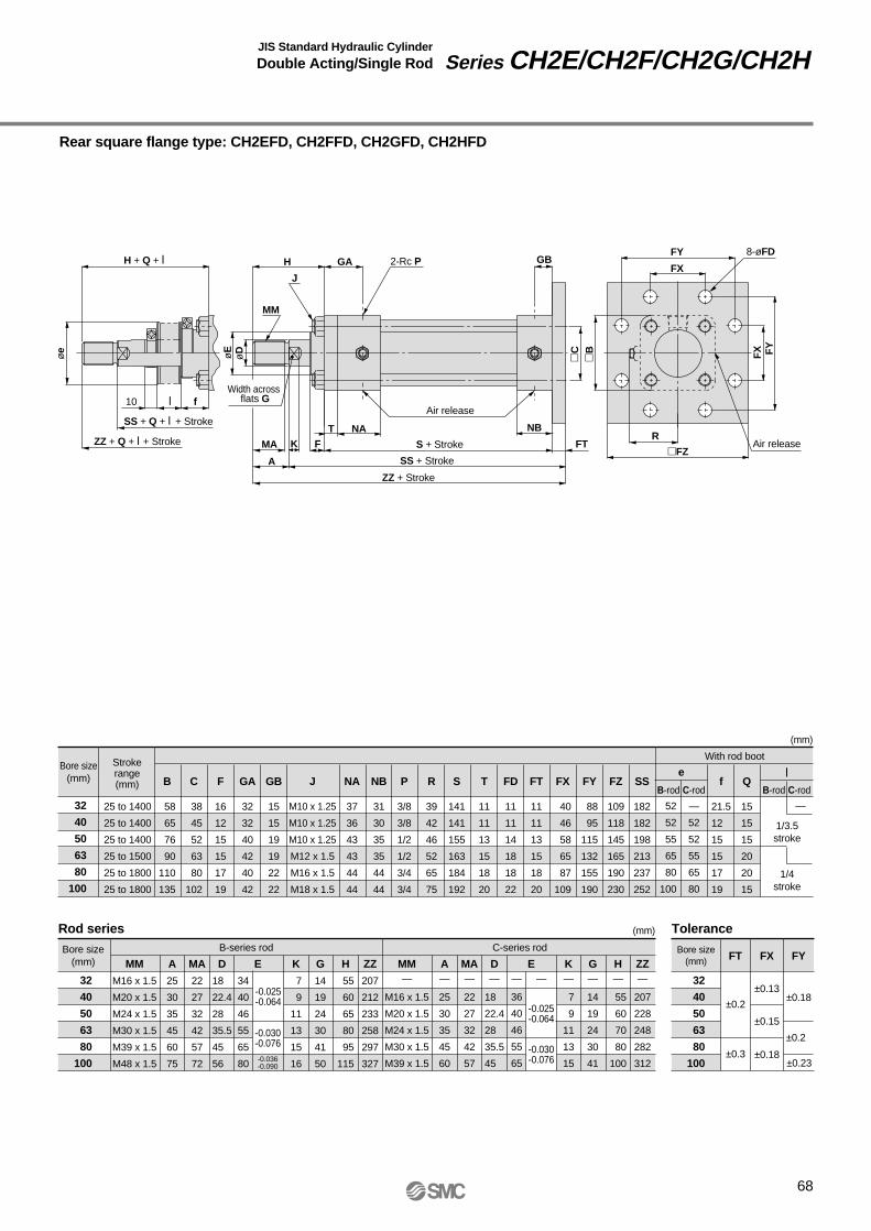
Rear square flange type: CH2EFD, CH2FFD, CH2GFD, CH2HFD
H + Q + l
SS + Q + l + Stroke
S + Stroke
SS + Stroke
ZZ + Stroke
ZZ + Q + l + Stroke
øe
øDøE
10 f
FY
MM
MA
A
K F
GA
l
C
B
2-Rc P8-øFD
GB
NB
J
H
NAT
FTR
FX
FY
FX
FZAir release
Air release
68
Rod series
Bore size(mm)
Strokerange(mm)
25 to 1400
25 to 1400
25 to 1400
25 to 1500
25 to 1800
25 to 1800
32
40
50
63
80
100
32
40
50
63
80
100
Tolerance
Bore size(mm)
l
With rod boot
B-series rod C-series rod
J
M10 x 1.25
M10 x 1.25
M10 x 1.25
M12 x 1.5
M16 x 1.5
M18 x 1.5
MM
M16 x 1.5
M20 x 1.5
M24 x 1.5
M30 x 1.5
M39 x 1.5
M48 x 1.5
A
25
30
35
45
60
75
MA
22
27
32
42
57
72
K
7
9
11
13
15
16
G
14
19
24
30
41
50
H
55
60
65
80
95
115
ZZ
207
212
233
258
297
327
D
18
22.4
28
35.5
45
56
MM—
M16 x 1.5
M20 x 1.5
M24 x 1.5
M30 x 1.5
M39 x 1.5
A—
25
30
35
45
60
MA—
22
27
32
42
57
K—
7
9
11
13
15
G—
14
19
24
30
41
H—
55
60
70
80
100
ZZ—
207
228
248
282
312
D—
18
22.4
28
35.5
45
(mm)
±0.2±0.18
±0.13
±0.15
±0.18
±0.2
±0.23±0.3
FT FX FY
B
58
65
76
90
110
135
C
38
45
52
63
80
102
GA
32
32
40
42
40
42
F
16
12
15
15
17
19
GB
15
15
19
19
22
22
S
141
141
155
163
184
192
FT
11
11
13
15
18
20
—
52
52
55
65
80
52
52
55
65
80
100
eFD
11
11
14
18
18
22
FX
40
46
58
65
87
109
FY
88
95
115
132
155
190
FZ
109
118
145
165
190
230
f
21.5
12
15
15
17
19
Q
15
15
15
20
20
15
SS
182
182
198
213
237
252
R
39
42
46
52
65
75
T
11
11
13
15
18
20
P
3/8
3/8
1/2
1/2
3/4
3/4
NA
37
36
43
43
44
44
NB
31
30
35
35
44
44
(mm)
Bore size(mm)
32
40
50
63
80
100
E
34
40
46
55
65
80
-0.025-0.064
-0.030-0.076
E—
36
40
46
55
65
—
-0.025-0.064
-0.030-0.076-0.036
-0.090
1/3.5stroke
1/4stroke
—
B-rod C-rodB-rod C-rod
JIS Standard Hydraulic Cylinder
Double Acting/Single Rod Series CH2E/CH2F/CH2G/CH2H
Width across flats G

Series CH2E/CH2F/CH2G/CH2H
Dimensions
Single clevis type: CH2ECA, CH2FCA, CH2GCA, CH2HCA
H + Q + l
SS + Q + l + Stroke
S + Stroke
Air release
SS + Stroke
ZZ + Stroke
ZZ + Q + l + Stroke
øe
øDøE
10 f
R
CX
MM
MA
A RR
K F
GA
l
C
2-Rc P øCDH9GB
NB
U
L
JH
NATB
Air release
69
-0.1-0.4
Rod series
Bore size(mm)
Strokerange(mm)
25 to 1400
25 to1400
25 to 1400
25 to 1500
25 to 1800
25 to 1800
32
40
50
63
80
100
32
40
50
63
80
100
Tolerance
Bore size(mm)
1/3.5stroke
With rod boot
B-series rod C-series rod
1/4stroke
J
M10 x 1.25
M10 x 1.25
M10 x 1.25
M12 x 1.5
M16 x 1.5
M18 x 1.5
MM
M16 x 1.5
M20 x 1.5
M24 x 1.5
M30 x 1.5
M39 x 1.5
M48 x 1.5
A
25
30
35
45
60
75
MA
22
27
32
42
57
72
K
7
9
11
13
15
16
G
14
19
24
30
41
50
H
55
60
65
80
95
115
ZZ
250
255
285
337.5
382.5
431
D
18
22.4
28
35.5
45
56
MM—
M16 x 1.5
M20 x 1.5
M24 x 1.5
M30 x 1.5
M39 x 1.5
A—
25
30
35
45
60
MA—
22
27
32
42
57
K—
7
9
11
13
15
G—
14
19
24
30
41
H—
55
60
70
80
100
ZZ—
250
280
327.5
367.5
416
D—
18
22.4
28
35.5
45
(mm)
+0.043 0
+0.062 0
+0.052 0
CDH9
B
58
65
76
90
110
135
C
38
45
52
63
80
102
GA
32
32
40
42
40
42
F
16
12
15
15
17
19
GB
15
15
19
19
22
22
S
141
141
155
163
184
192
CD
16
16
20
31.5
31.5
40
—
52
52
55
65
80
52
52
55
65
80
100
eCX
25
25
31.5
40
40
50
RR
16
16
20
31.5
31.5
40
SS
209
209
230
261
291
316
U
22
22
25
40
40
50
f
21.5
12
15
15
17
19
Q
15
15
15
20
20
15
L
38
38
45
63
72
84
R
39
42
46
52
65
75
T
11
11
13
15
18
20
P
3/8
3/8
1/2
1/2
3/4
3/4
NA
37
36
43
43
44
44
NB
31
30
35
35
44
44
(mm)
Bore size(mm)
32
40
50
63
80
100
E
34
40
46
55
65
80
-0.025-0.064
-0.030-0.076
E—
36
40
46
55
65
—
-0.025-0.064
-0.030-0.076-0.036
-0.090
l
—
B-rod C-rodB-rod C-rod
Width acrossflats G
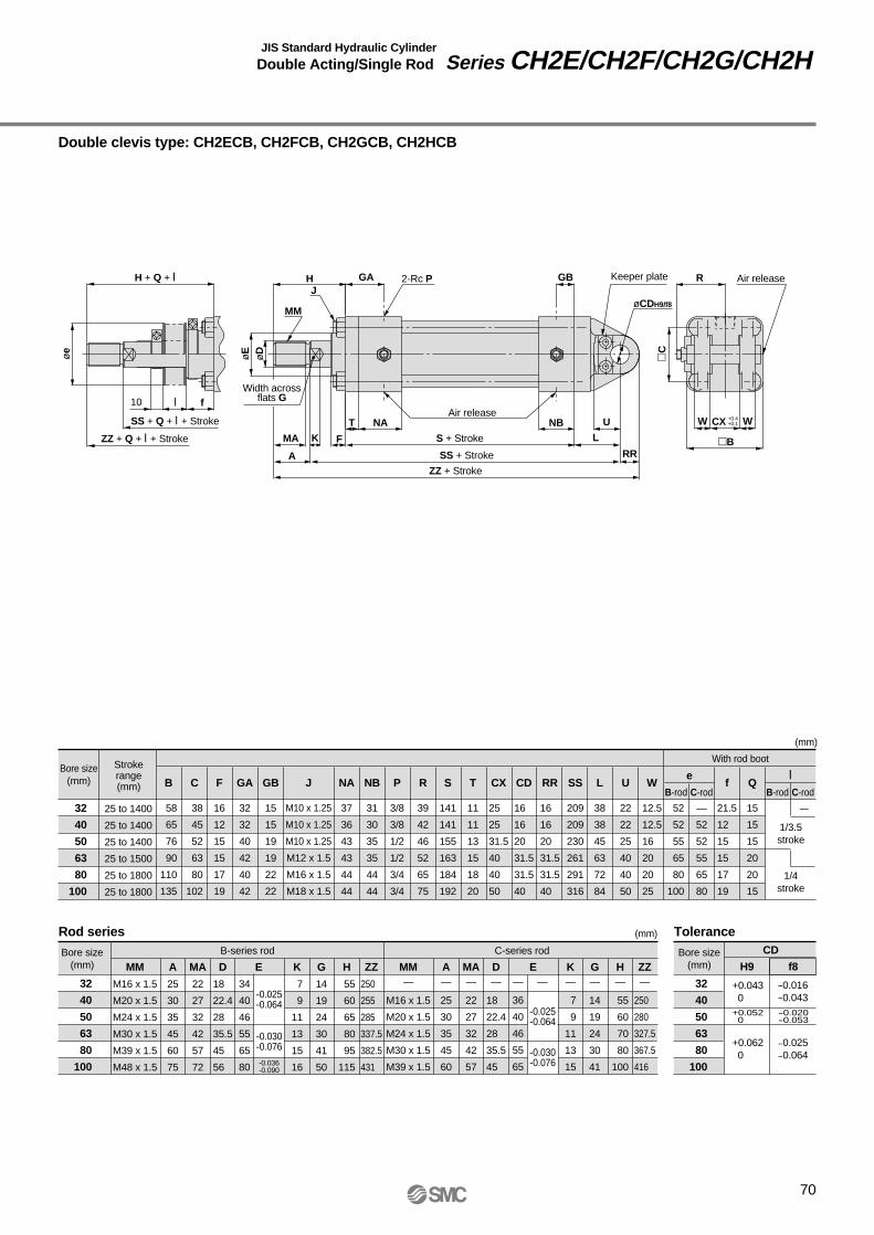
Double clevis type: CH2ECB, CH2FCB, CH2GCB, CH2HCB
H + Q + l
SS + Q + l + Stroke
S + Stroke
SS + Stroke
ZZ + Stroke
ZZ + Q + l + Stroke
øe
øDøE
10 f
R
W WCX
MM
MA
A
U
L
RR
K F
GA
l
C
2-Rc P
øCDH9/f8
GB
NB
JH
NAT
B
Air release
70
+0.4+0.1
Keeper plate Air release
Rod series
Bore size(mm)
Strokerange(mm)
25 to 1400
25 to 1400
25 to 1400
25 to 1500
25 to 1800
25 to 1800
32
40
50
63
80
100
32
40
50
63
80
100
Tolerance
Bore size(mm)
1/3.5stroke
With rod boot
B-series rod C-series rod
1/4stroke
J
M10 x 1.25
M10 x 1.25
M10 x 1.25
M12 x 1.5
M16 x 1.5
M18 x 1.5
MM
M16 x 1.5
M20 x 1.5
M24 x 1.5
M30 x 1.5
M39 x 1.5
M48 x 1.5
A
25
30
35
45
60
75
MA
22
27
32
42
57
72
K
7
9
11
13
15
16
G
14
19
24
30
41
50
H
55
60
65
80
95
115
ZZ
250
255
285
337.5
382.5
431
D
18
22.4
28
35.5
45
56
MM—
M16 x 1.5
M20 x 1.5
M24 x 1.5
M30 x 1.5
M39 x 1.5
A—
25
30
35
45
60
MA—
22
27
32
42
57
K—
7
9
11
13
15
G—
14
19
24
30
41
H—
55
60
70
80
100
ZZ—
250
280
327.5
367.5
416
D—
18
22.4
28
35.5
45
(mm)
+0.043 0
+0.062 0
+0.052 0
H9
CD
-0.016-0.043
-0.025-0.064
-0.020-0.053
f8
B
58
65
76
90
110
135
C
38
45
52
63
80
102
GA
32
32
40
42
40
42
F
16
12
15
15
17
19
GB
15
15
19
19
22
22
S
141
141
155
163
184
192
CD
16
16
20
31.5
31.5
40
—
52
52
55
65
80
52
52
55
65
80
100
eCX
25
25
31.5
40
40
50
RR
16
16
20
31.5
31.5
40
SS
209
209
230
261
291
316
L
38
38
45
63
72
84
f
21.5
12
15
15
17
19
Q
15
15
15
20
20
15
U
22
22
25
40
40
50
W
12.5
12.5
16
20
20
25
R
39
42
46
52
65
75
T
11
11
13
15
18
20
P
3/8
3/8
1/2
1/2
3/4
3/4
NA
37
36
43
43
44
44
NB
31
30
35
35
44
44
(mm)
Bore size(mm)
32
40
50
63
80
100
E
34
40
46
55
65
80
-0.025-0.064
-0.030-0.076
E—
36
40
46
55
65
—
-0.025-0.064
-0.030-0.076-0.036
-0.090
l
—
B-rod C-rodB-rod C-rod
JIS Standard Hydraulic Cylinder
Double Acting/Single Rod Series CH2E/CH2F/CH2G/CH2H
Width acrossflats G

Series CH2E/CH2F/CH2G/CH2H
Dimensions
Center trunnion type: CH2ETC, CH2FTC, CH2GTC, CH2HTC
H + Q + l
SS + Q + l + StrokeS + Stroke
SS + 1/2 stroke
ZZ + StrokeZZ + Q + l + Stroke
Airrelease
øe
øDøE
øTDe
910 f
R
J
RR
MM
MAA
K F GA
l
2-Rc P GB
NB
MH
NATBTXTY ±0.3 TY ±0.3
TZ
TTC
Airrelease
Airrelease
71
Rod series
Bore size(mm)
Strokerange(mm)
25 to 1800
25 to 1800
25 to 1800
25 to 1800
25 to 1800
25 to 1800
32∗ 1
40∗ 1
50∗ 1
63∗ 2
80
100 ∗ 1: CH2GTC is limited to 1400mm. ∗ 2: CH2GTC is limited to 1500mm.
32
40
50
63
80
100
Tolerance
Bore size(mm)
1/3.5stroke
With rod boot
B-series rod C-series rod
1/4stroke
J
M10 x 1.25
M10 x 1.25
M10 x 1.25
M12 x 1.5
M16 x 1.5
M18 x 1.5
MM
M16 x 1.5
M20 x 1.5
M24 x 1.5
M30 x 1.5
M39 x 1.5
M48 x 1.5
A
25
30
35
45
60
75
MA
22
27
32
42
57
72
K
7
9
11
13
15
16
G
14
19
24
30
41
50
H
55
60
65
80
95
115
ZZ
207
212
231
257
295
325
D
18
22.4
28
35.5
45
56
MM—
M16 x 1.5
M20 x 1.5
M24 x 1.5
M30 x 1.5
M39 x 1.5
A—
25
30
35
45
60
MA—
22
27
32
42
57
K—
7
9
11
13
15
G—
14
19
24
30
41
H—
55
60
70
80
100
ZZ—
207
226
247
280
310
D—
18
22.4
28
35.5
45
(mm)
-0.040-0.092
-0.050-0.112
TDe9
0-0.3
0-0.35
0-0.4
TX
B
58
65
76
90
110
135
C
38
45
52
63
80
102
GA
32
32
40
42
40
42
F
16
12
15
15
17
19
GB
15
15
19
19
22
22
S
141
141
155
163
184
192
SS
113
113
121
132
146
156
—
52
52
55
65
80
52
52
55
65
80
100
eRR
2
2
2.5
2.5
2.5
3
TD
20
20
25
31.5
31.5
40
TT
28
28
33
43
43
53
TX
58
69
85
98
118
145
f
21.5
12
15
15
17
19
Q
15
15
15
20
20
15
TY
20
20
25
31.5
31.5
40
TZ
98
109
135
161
181
225
R
39
42
46
52
65
75
T
11
11
13
15
18
20
P
3/8
3/8
1/2
1/2
3/4
3/4
NA
37
36
43
43
44
44
M
11
11
11
14
16
18
NB
31
30
35
35
44
44
(mm)
Bore size(mm)
32
40
50
63
80
100
E
34
40
46
55
65
80
-0.025-0.064
-0.030-0.076
E—
36
40
46
55
65
—
-0.025-0.064
-0.030-0.076-0.036
-0.090
l
—
B-rod C-rodB-rod C-rod
Width acrossflats G

Accessories (optional)
72
Single knuckle jointMaterial: Cast iron
Double knuckle jointMaterial: Cast iron
Rodseries
Rodseries
B-series
C-series
Part no.
IH2-03BIH2-04BIH2-05BIH2-06BIH2-08BIH2-10BIH2-03BIH2-05CIH2-06CIH2-06BIH2-10C
Bore size(mm)
3240506380
10040506380
100
3240506380
10040506380
100
Bore size(mm)
B-series
C-series
Part no.
YH2-03BYH2-04BYH2-05BYH2-06BYH2-08BYH2-10BYH2-03BYH2-05CYH2-06CYH2-06BYH2-10C
A 76
76
90
145
145
185
76
90
145
145
185
A 76
76
90
145
145
185
76
90
145
145
185
C41
41
50
75
75
95
41
50
75
75
95
D32
32
40
60
60
80
32
40
60
60
80
B 60
60
70
115
115
145
60
70
115
115
145
B 60
60
70
115
115
145
60
70
115
115
145
C25
25
30
45
45
57
25
30
45
45
57
D32
32
40
60
60
79
32
40
60
60
79
EM16 x 1.5
M20 x 1.5
M24 x 1.5
M30 x 1.5
M39 x 1.5
M48 x 1.5
M16 x 1.5
M20 x 1.5
M24 x 1.5
M30 x 1.5
M39 x 1.5
EM16 x 1.5
M20 x 1.5
M24 x 1.5
M30 x 1.5
M39 x 1.5
M48 x 1.5
M16 x 1.5
M20 x 1.5
M24 x 1.5
M30 x 1.5
M39 x 1.5
JM5 x 0.8
M5 x 0.8
M5 x 0.8
M6 x 1.0
M6 x 1.0
M8 x 1.25
M5 x 0.8
M5 x 0.8
M6 x 1.0
M6 x 1.0
M8 x 1.25
JM5 x 0.8
M5 x 0.8
M5 x 0.8
M6 x 1.0
M6 x 1.0
M8 x 1.25
M5 x 0.8
M5 x 0.8
M6 x 1.0
M6 x 1.0
M8 x 1.25
PM6 x 1.0
M6 x 1.0
M6 x 1.0
M8 x 1.25
M8 x 1.25
M10 x 1.5
M6 x 1.0
M6 x 1.0
M8 x 1.25
M8 x 1.25
M10 x 1.5
F26
31
36
50
61
76
26
31
40
50
63
H25
25
31.5
40
40
50
25
31.5
40
40
50
H25
25
31.5
40
40
50
25
31.5
40
40
50
K16
16
20
30
30
40
16
20
30
30
40
K16
16
20
30
30
40
16
20
30
30
40
L12.5
12.5
16
20
20
25
12.5
16
20
20
25
l
20
20
20
24
24
26
20
20
24
24
26
d16
16
20
31.5
31.5
40
16
20
31.5
31.5
40
+0.07 0
+0.07 0
+0.084 0
+0.1 0
+0.1 0
+0.1 0
+0.07 0
+0.084 0
+0.1 0
+0.1 0
+0.1 0
d16
16
20
31.5
31.5
40
16
20
31.5
31.5
40
+0.07 0
+0.07 0
+0.084 0
+0.1 0
+0.1 0
+0.1 0
+0.07 0
+0.084 0
+0.1 0
+0.1 0
+0.1 0
ødH10
K B
A
C
FJE
øD
H-0
.1-0
.4
2-ød
l ±0
.2
m T
HH
B
øD
30° d JIS class 2 thread
B
C
Part no.
KP-05
KP-08
KP-10
Part no.
NTH-040
NTH-050
NTH-060
NTH-080
NTH-100
NTH-125
NTH-040
NTH-050
NTH-060
NTH-080
NTH-100
Bore size(mm) Cap bolt
M6 x 10l
M8 x 12l
M10 x 14l
d
M16 x 1.5
M20 x 1.5
M24 x 1.5
M30 x 1.5
M39 x 1.5
M48 x 1.5
M16 x 1.5
M20 x 1.5
M24 x 1.5
M30 x 1.5
M39 x 1.5
B
22
27
32
41
55
70
22
27
32
41
55
C
25.4
31.2
37
47.3
63.5
80.8
25.4
31.2
37
47.3
63.5
D
21
26
31
40
54
69
21
26
31
40
54
H
10
12
14
17
20
26
10
12
14
17
20
32, 40, 50
63, 80
100
Bore size(mm)
32
40
50
63
80
100
40
50
63
80
100
B
32
44
44
H
12
18
22
m
6
9
11
T
4.5
4.5
6
d
6.5
9
11.5
l
20 ±0.2
24 ±0.2
26 ±0.2
Keeper plateMaterial: Rolled steel
Rod end nutMaterial: Carbon steel
Part no.
CDH-04
CDH-05
CDH-08
CDH-10
Bore size(mm)
32, 40
50
63, 80
100
C
1
1
1.5
2
L
62
76.5
93
117
m
2.5
3.5
3.5
6
T
4.8
4.8
4.8
6.3
d
14
18
29
35
Double clevis/Double knuckle pinMaterial: Rolled steel
Rod series
B-series
C-series
H0 -0
.15
t+0.15 0m
øD
f8
Df8
L
C
C
16
20
31.5
40
-0.016-0.043
-0.016-0.043
-0.016-0.043
-0.016-0.043
ødH10
H+0
.4+0
.1
A
C
LL B
J
E
K
øD
l
2-P keeper platemounting screw
Note) The pin, keeper plate and cap bolt are included with a double knuckle joint.
JIS Standard Hydraulic Cylinder
Double Acting/Single Rod Series CH2E/CH2F/CH2G/CH2H

Auto Switches: Proper Mounting Positions and Mounting Heights for Stroke End Detection
<Tie-rod mount type>
Reed switchesD-A5, D-A6D-A59W
Solid state switchesD-F5, D-J5D-F5NTLD-F5W, D-J59WD-F5BAL, D-F59F
<Band mount type>
Reed switches D-B5, D-B6, D-B59WSolid state switches D-G5, D-K59 D-G5W, D-K59W D-G5BAL D-G59F, D-G5NTL
Reed switchD-A3
Solid state switchesD-G39, D-K39
Reed switchD-A44
Auto Switch SpecificationsSeries CH2E/CH2F/CH2G/CH2H
73
Approx. Hs
Approx. Hs
Approx. Hs
Approx. Hs
Appr
ox. H
tAp
prox
. Ht
A A33(30)
Auto switch
A A33
12
Auto switch
A A36
49Auto switch
24.5
34 5656
G 1/2(applicable cable O.D ø6.8 to ø9.6)
A A49.5
Auto switch
G 1/2(applicable cable O.D. ø6.8 to ø11.5)
Dimensions inside ( ) are for solid state switch.

Auto switch mounting heights
D-F5, D-J5D-F5W, D-J59WD-F5BAL, D-F59F
D-F5NTL
D-B5, D-B6D-B59W
D-G5, D-K59D-G5W, D-K59W
D-G5BALD-G59F, D-G5NTL
D-A5, D-A6D-A59W
D-A3D-G39, D-K39
D-A44Bore size(mm)
Hs
35
34.5
34.5
38.5
38
38
43
41.5
42
48.5
46.5
48.5
58.5
56.5
59
66.5
65.5
67.5
Hs
33.5
32
32.5
38
36.5
37
43.5
41.5
42.5
50.5
48.5
50.5
59
57.5
59.5
69.5
68
71
Hs
—
—
—
72.5
71
71.5
78
76
77
85
83
85
93.5
92
94
104
102.5
105.5
Hs
—
—
—
82.5
81
81.5
88
86
87
95
93
95
103.5
102
104
114
112.5
115.5
32
40
50
63
80
100
CH2E
CH2F
CH2H
CH2E
CH2F
CH2H
CH2E
CH2F
CH2H
CH2E
CH2F
CH2H
CH2E
CH2F
CH2H
CH2E
CH2F
CH2H
Hs
35
34.5
34.5
38.5
38
38
42
41.5
42
47
46.5
47
57
56.5
57.5
66.5
65.5
67.5
Ht
29.5
30
29.5
32.5
33.5
33
36.5
36.5
36
43
43
43
55.5
55.5
55.5
67
67
67
Ht
29.5
30
29.5
32.5
33.5
33
36.5
36.5
36
43
43
43
55.5
55.5
55.5
67
67
67
Unit: mm
74
Proper auto switch mounting positions
D-G5, D-K59D-G5W, D-K59WD-G5BAL, D-G5NTL
D-B5, D-B64D-G59F
D-F5, D-J5D-F5W, D-J59WD-F5BAL
D-A5, D-A6D-A3, D-A44D-G39, D-K39
D-A59W D-F59F D-B59W
Auto switchtype
Bore size(mm)
32
40
50
63
80
100
A
15 Note)
16
16
19
23
26
A
19
20
20
23
27
30
A
21.5
22.5
22.5
25.5
29.5
32.5
A
25.5
26.5
26.5
29.5
33.5
36.5
D-F5NTL
A
26.5
27.5
27.5
30.5
34.5
37.5
A
17
18
18
21
25
28
A
15.5
16.5
16.5
19.5
23.5
26.5
A
18.5
19.5
19.5
22.5
26.5
29.5
Note) Auto switch models D-A3, D-A44, D-G39 and D-K39 cannot be mounted on ø32 bore size cylinders.
JIS Standard Hydraulic Cylinder
Double Acting/Single Rod Series CH2E/CH2F/CH2G/CH2H
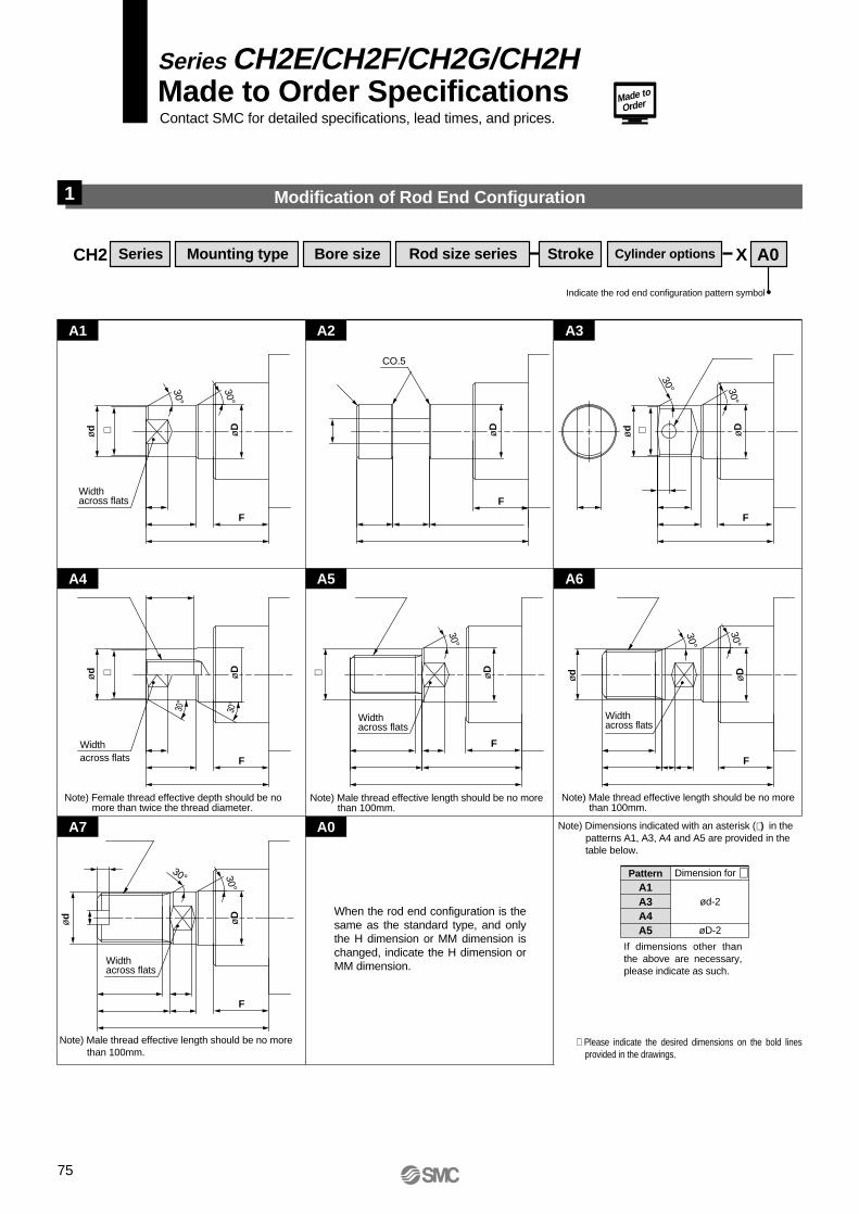
Series CH2E/CH2F/CH2G/CH2HMade to Order SpecificationsContact SMC for detailed specifications, lead times, and prices.
Made to
Order
Indicate the rod end configuration pattern symbol
When the rod end configuration is the same as the standard type, and only the H dimension or MM dimension is changed, indicate the H dimension or MM dimension.
Width across flats
CO.5
∗ ∗
30°
30° 30°
ød øD
F
F
F
FF
F
F
ød øD
øD
30°
Width across flats
Width across flats
∗
30°
ød
ød
øD
øD
∗ øD
30°
30°
30°30°
30°
30°
ød
øD
CH2 Series Mounting type Bore size Rod size series Stroke Cylinder options X A0
75
Modification of Rod End Configuration1
A1 A2 A3
A4 A5 A6
A7 A0
Dimension for ∗
ød-2
øD-2
PatternA1A3A4A5
Note) Female thread effective depth should be no more than twice the thread diameter.
Note) Male thread effective length should be no more than 100mm.
Note) Male thread effective length should be no more than 100mm.
Note) Male thread effective length should be no more than 100mm.
If dimensions other than the above are necessary, please indicate as such.
Note) Dimensions indicated with an asterisk (∗ ) in the patterns A1, A3, A4 and A5 are provided in the table below.
Widthacross flats
Width across flats
∗ Please indicate the desired dimensions on the bold lines provided in the drawings.

76

How to Order
JIS Standard Hydraulic CylinderDouble Acting/Double Rod
Series CH2EW/CH2FWø32, ø40, ø50, ø63, ø80, ø100
CH2 F W
W
BLA 50 100
CHD2 F BLA 50 100 A53With Auto Switch
Bore size 32 40 50 63 80100
32mm 40mm 50mm 63mm 80mm100mm
With auto switch(built-in magnet)
Tube materialAluminum alloyStainless steel
Nominal pressure3.5MPa7MPa
SymbolEF
Series type
Type: Double acting/Double Rod
Basic typeTransaxial foot typeAxial foot typeFront rectangular flange typeFront square flange typeCenter trunnion type
BLALBFAFCTC
Mounting types
2 pcs.1 pc.3 pcs.
"n" pcs.
NilS3n
Number of auto switches
Rod size seriesBC
B-series rod sizeC-series rod size
Cylinder stroke (mm)Refer to the standard stroke table on page 78.Refer to page 79 for minimum strokes with auto switch.
Part nos. for cylinderswith built-in magnets
Without auto switchNil
Auto switch type
In the case of cylinders with built-in magnets but no auto switches, do not indicate any auto switch type symbol.(Example) CHD2FWLA50-100
Without rod end nutWith rod end nutWith double side cushionWithout cushionWith front cushionWith rear cushion
Cushion
NilANilNRH
Cylinder options
3.5MPa7 MPa
Rod end nut
∗ Indicate in alphabetical order.
∗ Refer to page 78.
∗ Select applicable auto switch models from the table below.
77
Applicable Auto Switches:
Type Electricalentry
Terminalconduit
Terminalconduit
Indi
cato
rlig
ht
3-wire (NPN equiv.)
Load voltage
––––
100V, 200V––
200V or less––
100V, 200V
––
ACDC
Lead wire length (m)∗
0.5(Nil)
3(L)
5(Z)
––––––––––––––
––––––––––
––––––––––––––––––
IC circuit
IC circuit
IC circuit
IC circuit
IC circuit
IC circuit
Applicableload
5V12V12V
5V, 12V5V, 12V
12V
—
5V, 12V
—12V
5V, 12V12V
5V, 12V
12V
5V, 12V
A56A53A54A67A64––––––
A59WF59F5PJ51J59––––
F59WF5PWJ59WF5BAF5NTF59F
––B53B54––
B64 A33∗∗
A34∗∗
A44∗∗
B59WG59G5P––
K59 G39∗∗
K39∗∗
G59WG5PWK59WG5BAG5NTG59F
––Yes
Yes
Yes
Diagnostic indication (2-color display)
Diagnostic indication (2-color display)
Water resistant (2-color display)With timer
With diagnostic output (2-color display)
3-wire (NPN)3-wire (PNP)
2-wire
3-wire (NPN)2-wire
3-wire (NPN)3-wire (PNP)
2-wire
3-wire (NPN)4-wire (NPN)
2-wire
Ree
d s
witc
hS
olid
sta
te s
witc
h
––
––
––
––
––
No
—
—
∗ Lead wire length symbols: 0.5m ....... Nil (Example) A533m ........ L A53L5m ........ Z A53Z
––PLC
Relay, PLCPLC
Relay, PLCPLC
RelayPLC
RelayPLC
24V
24V
24V
Grommet
Grommet
Grommet
DIN terminal
Grommet
Wiring (output)Special functionAuto switch type
Tie-rodmount
Bandmount
––
––
––
Refer to pages 115 to 119 for auto switch switch specifications.
100V, 200V
∗∗ Cannot be mounted on ø32 bore size cylinders.Note) • The standard lead wire length is 0.5m. However, the standard length for G5NTL, G5BAL, F5NTL and F5BAL is 3m.
• Solid state switches marked "" are produced upon receipt of order.
Port and cushion valve positions

78
Model
Tube material
Nominal pressure
Bore size
Auto switch mounting
Model
Action
Fluid
Nominal pressure
Maximumallowable pressure
Proof pressure
Minimum operating pressure
Ambient andfluid temperature
Piston speed
Cushion
Rod end threads
Thread tolerance
Stroke length tolerance
Models
Specifications
JIS symbol
CH2EW
Aluminum alloy
3.5MPa
Applicable
CH2EW
CH2FW
Stainless steel
7
Applicable
32, 40, 50, 63, 80, 100mm
CH2FW
Double acting/Double rod
Hydraulic fluid
0.3MPa
Without auto switch: –10° to 80°C
With auto switch: –10° to 60°C
8 to 300mm/s
Cushion seal type
Male threads
JIS class 2
3.5MPa
3.5MPa
5.0MPa
7MPa
10.5MPa
B-rod: 13.5MPaC-rod: 11MPa
Made to
OrderPages 75 to 76
32
40
50
63
80
100
Standard Strokes
Standard strokes (mm)
25 to 800
25 to 800
25 to 800
25 to 800
25 to 1000
25 to 1000
Bore size(mm)
Auto Switch mounting Bracket Part Nos.
Model
CH2E
CH2F
Bore size(mm)
Auto switch type
D-A3, D-A4D-G3, D-K3
D-B5, D-B6D-G5, D-K5
D-A5, D-A6D-F5, D-J5
32
40
50
63
80
100
32
40
50
63
80
100
—
BD1-04M
BD1-05M
BD1-06M
BD1-08M
BD1-10M
—
BDS-04M
BDS-05M
BDS-06M
BDS-08M
BDS-10M
BA-32
BA-04
BA-05
BA-06
BA-08
BA-10
BAF-32
BAF-04
BAF-05
BAF-06
BAF-08
BAF-10
BT-06
BT-06
BT-06
BT-08
BT-16
BT-18
BT-06
BT-06
BT-06
BT-08
BT-16
BT-18
B
(Basic Type)
LA, LB
(Foot type)
FA, FB, FC, FD, FY,FZ(Flange type)
CA, CB(Single clevis type)
TC(Center trunnion type)
Port and Cushion Valve Positions
Mountingtype
Position
Symbol Nil A C D E F G H
Port: TopCushion valve:Right
Port: RightCushion valve:Bottom
Port: LeftCushion valve:Top
Port: TopCushion valve:Left
Port: TopCushion valve:Bottom
Port: RightCushion valve:Top
Port: RightCushion valve:Left
Port: LeftCushion valve:Right
JIS Standard Hydraulic Cylinder
Double Acting/Double Rod Series CH2EW/CH2FW
to 100mm , 101 to 250mm ,251 to 630mm , 631 to 1000mm
+0.8 0
+1.25 0
+1.0 0
+1.4 0
Note) Refer to page 136 for definitions of terms related to pressure.
Note) Refer to the stroke selection Table in Technical Data 2, starting with page 123 to determine stroke limitation depending on the type of mounting brackets that will be used. Then make your selection.
: Piping port
∗ The cylinder's exterior dimensions represented here are as seen from the end rod of the cylinder.
: Cushion valve
mm
mm
mm
mm

79
Weights
Theoretical Output
Unit: kg
Basic Transaxialfoot
Axialfoot
Center trunnion
Squareflange
Rectangularflange(7MPa)
Additionalweight
(per 10mm stroke)
2.94 2.93 3.82 3.79 6.37 6.27 9.75 9.1615.0014.3621.8221.26
3.38 3.37 4.41 4.38 7.45 7.3511.3610.7717.6917.0526.4225.86
3.44 3.43 4.40 4.37 7.17 7.0711.3710.7817.3616.7225.2424.68
3.43 3.42 4.41 4.38 7.21 7.1111.2910.7017.0216.3825.4724.91
3.79 3.78 4.91 4.88 8.33 8.2312.6512.0619.5918.9529.2928.73
3.93 3.92 5.12 5.09 8.97 8.8713.6313.0420.3519.7132.6332.06
0.040.040.080.080.090.100.170.170.240.260.410.46
Mountingtype
ModelBoresize (mm)
32
40
50
63
80
100
CH2ECH2FCH2ECH2FCH2ECH2FCH2ECH2FCH2ECH2FCH2ECH2F
B LA FC TC LB FA
B-s
erie
s ro
d
Basic Transaxialfoot
Axialfoot
Center trunnion
Squareflange
Additionalweight
(per 10mm stroke )
Mountingtype
ModelBoresize (mm)
40
50
63
80
100
CH2ECH2FCH2ECH2FCH2ECH2FCH2ECH2FCH2ECH2F
B LA FC TC LB FA
B-s
erie
s ro
dC
-ser
ies
rod
Rectangularflange(7MPa)
3.74 3.71 6.21 6.11 9.44 8.8614.5613.9220.7620.20
4.33 4.30 7.29 7.1911.0510.4717.2516.6125.3624.80
4.32 4.29 7.01 6.9111.0610.4816.9216.2824.1823.62
4.33 4.30 7.05 6.9510.9810.4016.5815.9424.4123.85
4.83 4.80 8.17 8.0712.3411.7619.1518.5128.2327.67
5.04 5.01 8.81 8.7113.3212.7419.9119.2731.5731.01
0.070.070.070.080.140.140.180.210.290.30
Bore size(mm)
Rod size(mm)
Piston area(mm²)
Nominal pressure (MPa)
Unit: N
C-s
erie
s ro
d
Series CH2EW/CH2FW
3240506380
10040506380
100
18 22.428 35.545 56 18 22.428 35.545
550 862 1347 2126 3434 5388 1002 1569 2500 4035 6260
1 550 862 1347 2126 3434 5388 1002 1569 2500 4035 6260
3.51923301747157442
12020 18859 350654908751
14121 21911
5274843116735
10632 17172 26941 50087843
12501 20174 31302
7384760359429
14885 24041 37718 7012
10980 17502 28243 43823
Rod Sizes
B-series
C-series
32
18
—
40
22.4
18
50
28
22.4
63
35.5
28
80
45
35.5
100
56
45
Rod size series∗
Bore size(mm)
(mm)
Accessories (optional)
∗ Based on JIS B8367.
Cushion Stroke
Bore size (mm)
Effective cushion stroke
(mm)
40
16
32
16
50
17
63
16
80
20
100
23
Single knuckle, Double Knuckle
Lock nut, Knuckle pin
Refer to page 72.
Refer to the table for double acting/single rod on page 58.
Minimum Strokes for Auto Switch Mounting
Auto Switches: Proper Mounting Positions and Mounting Heights for Stroke End DetectionSame as double acting/single rod: Refer to page 74.
∗ Consult with SMC.
Hydraulic Fluid Compatibility
Hydraulic fluid Compatibility
Compatible
Compatible
Compatible
∗Not compatible
Standard mineral hydraulic fluid
W/O hydraulic fluid
O/W hydraulic fluid
Water/Glycol hydraulic fluid
Phosphate hydraulic fluid

80
Construction
Parts list Replacement parts: Seal kitsNo.
1
2
3
4
5
6
7
8
9
10
11
12
13
14
15
16
17
18
19
20
21
22
23
24
25
26
27
28
29
30
31
32
33
Description Material
Carbon steel
Carbon steel
Carbon steel
Carbon steel
Aluminum alloy
Rolled steel
Copper alloy
Copper alloy
Carbon steel
Carbon steel
Carbon steel
Carbon steel
Carbon steel
Carbon steel
Alloy steel
Carbon steel
Alloy steel
Bearing steel
Carbon tool steel
Carbon tool steel
Carbon tool steel
NBR
NBR
NBR
NBR
NBR
NBR
NBR
NBR
–
NBR
–
Note
Hard anodized
Hard chromium electroplated
Hard chromium electroplated
Hard chromium electroplated
Hard chromium electroplated
Rod cover
Seal holder (B-series rod)
Seal holder (C-series rod)
Retainer
Cylinder tube
Piston
Cushion ring
Bushing (B-series rod)
Bushing (C-series rod)
Piston rod A (B-series rod)
Piston rod A (C-series rod)
Piston rod B (B-series rod)
Piston rod B (C-series rod)
Tie-rod
Tie-rod nut
Cushion valve
Lock nut
Air release valve
Check ball
Spring pin (B-series rod)
Spring pin (C-series rod)
Snap ring
Scraper (B-series rod)
Scraper (C-series rod)
Rod seal (B-series rod)
Rod seal (C-series rod)
Piston seal
Cylinder tube gasket
Holder gasket
Cushion valve seal
Cushion seal
Gasket
Magnet
Aluminum alloy
Stainless steel
CH2E
CH2F
Bore size(mm)
Seal kit no.Kit components
B-series rod C-series rod
32
40
50
63
80
100
CH2EW40B-PSCH2FW40B-PS
CH2EW50B-PSCH2FW50B-PS
CH2EW63B-PSCH2FW63B-PS
CH2EW80B-PSCH2FW80B-PS
CH2EW100B-PSCH2FW100B-PS
CH2EW40C-PSCH2FW40C-PS
CH2EW50C-PSCH2FW50C-PS
CH2EW63C-PSCH2FW63C-PS
CH2EW80C-PSCH2FW80C-PS
CH2EW100C-PSCH2FW100C-PS
JIS Standard Hydraulic Cylinder
Double Acting/Double Rod Series CH2EW/CH2FW
∗ Seal kits consist of items 23 through 32 and can be ordered using the seal kit number for each bore size.
CH2EW32B-PSCH2FW32B-PS
CH2EW32C-PSCH2FW32C-PS
Nos. 23 through 32from the chart at left
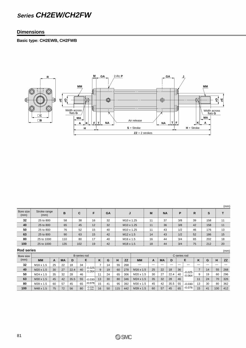
81
Dimensions
Basic type: CH2EWB, CH2FWB
S + Stroke H + StrokeH
ZZ + 2 strokes
øD
øE
R
MM
MA
A
MA
MM
AK KF T
GA
C
2-Rc P GA JM
NA NA
Bore size(mm)
Stroke range(mm)
25 to 800
25 to 800
25 to 800
25 to 800
25 to 1000
25 to 1000
38
45
52
63
80
102
58
65
76
90
110
135
M10 x 1.25
M10 x 1.25
M10 x 1.25
M12 x 1.5
M16 x 1.5
M18 x 1.5
32
32
40
42
40
42
11
11
11
14
16
18
3/8
3/8
1/2
1/2
3/4
3/4
158
158
176
186
202
212
16
12
15
15
17
19
39
42
46
52
65
75
32
40
50
63
80
100
32
40
50
63
80
100
Bore size(mm)
B-series rod C-series rod
MM
M16 x 1.5
M20 x 1.5
M24 x 1.5
M30 x 1.5
M39 x 1.5
M48 x 1.5
D
18
22.4
28
35.5
45
56
MA
22
27
32
42
57
72
A
25
30
35
45
60
75
34
40
46
55
65
80
G
14
19
24
30
41
50
H
55
60
65
80
95
115
ZZ
268
278
306
346
392
442
A—
25
30
35
45
60
-0.025-0.064 -0.025
-0.064
-0.030-0.076
-0.030-0.076-0.036-0.090
K
7
9
11
13
15
16
MM—
M16 x 1.5
M20 x 1.5
M24 x 1.5
M30 x 1.5
M39 x 1.5
MA—
22
27
32
42
57
D—
18
22.4
28
35.5
45
K—
7
9
11
13
15
G—
14
19
24
30
41
H—
55
60
70
80
100
ZZ—
268
296
326
362
412
—
36
40
46
55
65
—
(mm)
BFT
(mm)Rod series
Air release
Series CH2EW/CH2FW
B C F RJ M
37
36
43
43
44
44
NA P S
11
11
13
15
18
20
TGAø
D
øE
E E
Width acrossflats G
Width acrossflats G

104
104
116
114
124
122
82
Transaxial foot type: CH2EWLA, CH2FWLA
S + Stroke H + StrokeH
ZZ + 2 strokes
Z + Stroke SS + Stroke
øD
øE
R
LH
LT
LX
BB
MM
MA
A
MA
MM
A
K
SS
Y YX X K
F LW LW
GA
C
2-Rc P
GA
M
J
NA NA
32
40
50
63
80
100
Bore size(mm)
B-series rod C-series rod
MM
M16 x 1.5
M20 x 1.5
M24 x 1.5
M30 x 1.5
M39 x 1.5
M48 x 1.5
A
25
30
35
45
60
75
MA
22
27
32
42
57
72
K
7
9
11
13
15
16
34
40
46
55
65
80
G
14
19
24
30
41
50
H
66
71
78
95
113
135
ZZ
268
278
306
346
392
442
D
18
22.4
28
35.5
45
56
E MM—
M16 x 1.5
M20 x 1.5
M24 x 1.5
M30 x 1.5
M39 x 1.5
A—
25
30
35
45
60
K—
7
9
11
13
15
G—
14
19
24
30
41
H—
66
73
85
98
120
ZZ—
268
296
326
362
412
D—
18
22.4
28
35.5
45
B F
J
(mm)Rod series
øD øE
Bore size(mm)
Strokerange(mm)
25 to 800
25 to 800
25 to 800
25 to 800
25 to 1000
25 to 1000
109
118
145
165
190
230
58
65
76
90
110
135
38
45
52
63
80
102
14
10
10
10
11
11
21
21
27
27
22
22
11
11
14
18
18
22
35
37.5
45
50
60
71
±0.15±0.18
±0.20
±0.23±0.25
-0.025-0.064
-0.030-0.076
14
14
17
19
24
27
88
95
115
132
155
190
M10 x 1.25
M10 x 1.25
M10 x 1.25
M12 x 1.5
M16 x 1.5
M18 x 1.5
13
13
18
20
24
28
11
11
11
14
16
18
3/8
3/8
1/2
1/2
3/4
3/4
39
42
46
52
65
75
136
136
150
156
166
172
57
57
60
71
74
85
14
14
18
19
20
22
29
29
35
41
45
53
32
40
50
63
80
100
(mm)
CBBB LX RLWGA LTLHF J YXSS ZSPM
37
36
43
43
44
44
NACD
4-øCD
-0.036-0.090
—
36
40
46
55
65
—E
-0.025-0.064
-0.030-0.076
MA—
22
27
32
42
57
JIS Standard Hydraulic CylinderDouble Acting/Double Rod Series CH2EW/CH2FW
Width across flats G
Width acrossflats G

MA—
22
27
32
42
57
83
Dimensions
Axial foot type: CH2EWLB, CH2FWLB
S + Stroke
Z + Stroke
SS + Stroke
H + StrokeH
ZZ + 2 strokes
øD
øE
LH
LW
LT
R
LX
BB
MM
MA
A
MA
MM
AK KF GAC
2-Rc PGA
MJ
NAT
X1Y1
NA T
X1
Bore size(mm)
Strokerange(mm)
25 to 800
25 to 800
25 to 800
25 to 800
25 to 1000
25 to 1000
M10 x 1.25
M10 x 1.25
M10 x 1.25
M12 x 1.5
M16 x 1.5
M18 x 1.5
32
32
40
42
40
42
39
42
46
52
65
75
30
33
37
45
50
55
37
36
43
43
44
44
222
222
246
270
302
322
40
46
58
65
87
109
3/8
3/8
1/2
1/2
3/4
3/4
8
8
8
10
12
12
40
43
50
60
72
85
11
11
11
14
16
18
32
32
35
42
50
55
11
11
13
15
18
20
220
220
241
263
287
307
158
158
176
186
202
212
16
12
15
15
17
19
11
11
14
18
18
22
38
45
52
63
80
102
58
65
76
90
110
135
62
69
85
98
118
150
32
40
50
63
80
100
32
40
50
63
80
100
Bore size(mm)
B-series rod C-series rod
MM
M16 x 1.5
M20 x 1.5
M24 x 1.5
M30 x 1.5
M39 x 1.5
M48 x 1.5
A
25
30
35
45
60
75
MA
22
27
32
42
57
72
K
7
9
11
13
15
16
G
14
19
24
30
41
50
H
55
60
65
80
95
115
ZZ
268
278
306
346
392
442
D
18
22.4
28
35.5
45
56
34
40
46
55
65
80
E MM—
M16 x 1.5
M20 x 1.5
M24 x 1.5
M30 x 1.5
M39 x 1.5
A—
25
30
35
45
60
K—
7
9
11
13
15
G—
14
19
24
30
41
H—
55
60
70
80
100
ZZ—
268
296
326
362
412
D—
18
22.4
28
35.5
45
E
(mm)
B
F
(mm)Rod series
Air release
CBBB GA LX PLWLTF J LH NA TSSS ZX1
13
13
15
18
20
23
Y1RMCD
øD øE
Y1
4-øCD
Series CH2EW/CH2FW
±0.15±0.13
±0.15
±0.18±0.25
-0.025-0.064
-0.030-0.076-0.036-0.090
—
36
40
46
55
65
—
-0.025-0.064
-0.030-0.076
Width acrossflats G Width across
flats G

84
Front rectangular flange type: CH2EWFA, CH2FWFA
S + Stroke H + StrokeHZZ + 2 strokes
øDøE
FY
BB
FX
FZ
SS
MM
MA
A
MAM
MM
AK
K
F GA1
C
2-Rc P GA2
T F
J
NAFT NA
Bore size(mm)
Stroke range(mm)
25 to 800
25 to 800
25 to 800
25 to 800
25 to 1000
25 to 1000
M10 x 1.25
M10 x 1.25
M10 x 1.25
M12 x 1.5
M16 x 1.5
M18 x 1.5
21
21
27
27
22
22
30
30
30
35
35
40
39
42
46
52
65
75
109
118
145
165
190
230
3/8
3/8
1/2
1/2
3/4
3/4
11
11
13
15
18
20
16
12
15
15
17
19
38
45
52
63
80
102
58
65
76
90
110
135
62
69
85
98
118
150
32
40
50
63
80
100
32
40
50
63
80
100
Bore size(mm)
B-series rod C-series rod
MM
M16 x 1.5
M20 x 1.5
M24 x 1.5
M30 x 1.5
M39 x 1.5
M48 x 1.5
A
25
30
35
45
60
75
MA
22
27
32
42
57
72
K
7
9
11
13
15
16
G
14
19
24
30
41
50
H
66
71
78
95
113
135
ZZ
268
278
306
346
392
442
D
18
22.4
28
35.5
45
56
34
40
46
55
65
80
E MM—
M16 x 1.5
M20 x 1.5
M24 x 1.5
M30 x 1.5
M39 x 1.5
A—
25
30
35
45
60
K—
7
9
11
13
15
G—
14
19
24
30
41
H—
66
73
85
98
120
ZZ—
268
296
326
362
412
D—
18
22.4
28
35.5
45
(mm)
B
(mm)Rod series
Air release
CBBB GA1
32
32
40
42
40
42
GA2
136
136
150
156
166
172
SFZF
11
11
14
18
18
22
FD
11
11
13
15
18
20
FT
88
95
115
132
155
190
FX
40
46
58
65
87
109
FY J R TSSPM
37
36
43
43
44
44
NA
øD
øE
4-øFD R
±0.2±0.18
±0.13
±0.15
±0.18
±0.2
±0.23±0.3
-0.025-0.064
-0.030-0.076-0.036-0.090
—
36
40
46
55
65
—
E
-0.025-0.064
-0.030-0.076
11
11
11
14
16
18
MA—
22
27
32
42
57
JIS Standard Hydraulic Cylinder
Double Acting/Double Rod Series CH2EW/CH2FW
Width acrossflats G
Width acrossflats G

85
Dimensions
Square flange type: CH2EWFC, CH2FWFC
S + Stroke H + StrokeA SS FT
ZZ + 2 strokes
8-øFD
B
øE
øD
FX
FY
FY
FX
RFZ
MM MM
H GA
2-Rc P
Air release
GA
NA T F A
K MA
NAMA K F
Bore size(mm)
Stroke range(mm)
25 to 800
25 to 800
25 to 800
25 to 800
25 to 1000
25 to 1000
M10 x 1.25
M10 x 1.25
M10 x 1.25
M12 x 1.5
M16 x 1.5
M18 x 1.5
11
11
11
14
16
18
11
11
13
15
18
20
11
11
14
18
18
22
3/8
3/8
1/2
1/2
3/4
3/4
16
12
15
15
17
19
38
45
52
63
80
102
58
65
76
90
110
135
32
40
50
63
80
100
32
40
50
63
80
100
Bore size(mm)
B-series rod C-series rod
MM
M16 x 1.5
M20 x 1.5
M24 x 1.5
M30 x 1.5
M39 x 1.5
M48 x 1.5
A
25
30
35
45
60
75
MA
22
27
32
42
57
72
K
7
9
11
13
15
16
G
14
19
24
30
41
50
H
66
71
78
95
113
135
ZZ
268
278
306
346
392
442
D
18
22.4
28
35.5
45
56
34
40
46
55
65
80
E MM—
M16 x 1.5
M20 x 1.5
M24 x 1.5
M30 x 1.5
M39 x 1.5
A—
25
30
35
45
60
K—
7
9
11
13
15
G—
14
19
24
30
41
H—
66
73
85
98
120
ZZ—
268
296
326
362
412
D—
18
22.4
28
35.5
45
(mm)
J
(mm)Rod series
Air release
CB FT
40
46
58
65
87
109
FX
88
95
115
132
155
190
FYFDF J
109
118
145
165
190
230
FZ
21
21
27
27
22
22
GA M
37
36
43
43
44
44
NA R
136
136
150
156
166
172
S
30
30
30
35
35
40
SS
11
11
13
15
18
20
TP
C
øE
øD
Series CH2EW/CH2FW
M
±0.2
±0.3
±0.13±0.18
±0.23
±0.2
±0.15
±0.18
-0.025-0.064
-0.030-0.076-0.036-0.090
—
36
40
46
55
65
E
-0.025-0.064
—
-0.030-0.076
MA—
22
27
32
42
57
39
42
46
52
65
75
Width acrossflats G
Width acrossflats G

86
Center trunnion type: CH2EWTC, CH2FWTC
S + Stroke
SS + 1/2 stroke
H + StrokeH
ZZ + 2 strokes
øE
øD
R
J
øTDe
9
RR
TX
TZ
MM
MA
A
MA
A
MM
K
K
F GA
C
2-Rc P GA
NA T MNAT TT
Bore size(mm)
Strokerange(mm)
25 to 800
25 to 800
25 to 800
25 to 800
25 to 1000
25 to 1000
M10 x 1.25
M10 x 1.25
M10 x 1.25
M12 x 1.5
M16 x 1.5
M18 x 1.5
11
11
11
14
16
18
11
11
13
15
18
20
32
32
40
42
40
42
3/8
3/8
1/2
1/2
3/4
3/4
37
36
43
43
44
44
98
109
135
161
181
225
16
12
15
15
17
19
38
45
52
63
80
102
58
65
76
90
110
135
32
40
50
63
80
100
32
40
50
63
80
100
Bore size(mm)
B-series rod C-series rod
MM
M16 x 1.5
M20 x 1.5
M24 x 1.5
M30 x 1.5
M39 x 1.5
M48 x 1.5
A
25
30
35
45
60
75
MA
22
27
32
42
57
72
K
7
9
11
13
15
16
G
14
19
24
30
41
50
H
55
60
65
80
95
115
ZZ
268
278
306
346
392
442
D
18
22.4
28
35.5
45
56
34
40
46
55
65
80
E MM—
M16 x 1.5
M20 x 1.5
M24 x 1.5
M30 x 1.5
M39 x 1.5
A—
25
30
35
45
60
K—
7
9
11
13
15
G—
14
19
24
30
41
H—
55
60
70
80
100
ZZ—
268
296
326
362
412
D—
18
22.4
28
35.5
45
—
36
40
46
55
65
—E
(mm)
B
F
(mm)Rod series
Air releaseAirrelease
CB
113
113
121
132
146
156
SSGA MF J
158
158
176
186
202
212
S
39
42
46
52
65
75
R
2
2
2.5
2.5
2.5
3
RR TZT
20
20
25
31.5
31.5
40
TDe9
28
28
33
43
43
53
TT
20
20
25
31.5
31.5
40
TY
58
69
85
98
118
145
TXPNA
øE
øD
TY ±0.3 TY ±0.3
-0.040-0.092
-0.050-0.112
-0.025-0.064
-0.030-0.076
-0.025-0.064
-0.030-0.076-0.036-0.090
0-0.3
0-0.35
0-0.4
MA—
22
27
32
42
57
JIS Standard Hydraulic Cylinder
Double Acting/Double Rod Series CH2EW/CH2FW
Width acrossflats G
Width acrossflats G

Part nos. for cylinderswith built-in magnets
How to Order
Number of auto switches
Without auto switchNil
Auto switch type
Mounting types
With auto switch(built-in magnet)
87
Tie-rod Type Low Pressure Hydraulic CylinderDouble Acting/Single Rod
Series CHAø40, ø50, ø63, ø80, ø100, ø125, ø160
CHA 40 100LLWith Auto Switch
Bore size
∗ Indicate in alphabetical order.
Cylinder options
CHDA 40 100 A34
BLFGCDTU
Basic typeAxial foot typeFront flange typeRear flange typeSingle clevis typeDouble clevis typeCenter trunnion typeFront trunnion type
40506380
100
40mm 50mm 63mm 80mm100mm A
lum
inum
tube
Bore size40506380
100125160
40mm 50mm 63mm 80mm100mm125mm160mm
Alu
min
um tu
beS
teel
tube
Aluminum alloySteel tube
NilF
Tube material
Cylinder stroke (mm)Refer to the standard stroke table on page 88.
NilJKNilNRH
Without rod bootNylon tarpaulinNeoprene cloth
Both sidesWithout cushion
With front cushionWith rear cushion
Rod boot
Cushion
2 pcs.1 pc.3 pcs.
"n" pcs.
NilS3n
3.5MPa
∗ Select applicable auto switch models from the table below.
In the case of cylinders with built-in magnets but no auto switches, do not indicate any auto switch type symbol.
(Example) CHDAB50-100Applicable Auto Switches:
Typ
e Electricalentry
Indi
cato
rlig
ht
3-wire (NPN equiv.)
Load voltage
—
—
ACDC
Lead wire length (m)∗
0.5(Nil)
3(L)
5(Z)
IC circuit
—
IC circuit
—
IC circuit
—
IC circuit—
IC circuit
—
IC circuit
—
Applicableload
100V200V
100V200V
100V200V
Yes
Yes
Yes
Diagnostic indication (2-color display)
Diagnostic indication(2-color display)
With diagnostic output (2-color display)
Latch type with diagnostic output (2-color display)
With timer
Water resistant (2-color display)
No 2-wire
Ree
d s
witc
hS
olid
sta
te s
witc
h
A56A53
A54
A67A64———
A59WF59F5P
J51
J59——
F59WF5PWJ59WF5BAF5NTF59F
F5LF
—
—
RelayPLC
RelayPLC
Relay, PLC
RelayPLC
PLC
PLC
PLC
24V
24V
—
— —
—
24V
Grommet
Grommet
Grommet
Grommet
DIN terminal
Terminalconduit
Terminalconduit
Wiring(output)
Special function
—
B53
B54
—B64A33A34A44
B59W——
—
—G39K39———
———
—
———
————
———
——
—
—————
—
——
Auto switch type
—
—200V or less
—
—
—
3-wire (NPN)3-wire (PNP)
2-wire
3-wire (NPN)2-wire
3-wire (NPN)3-wire (PNP)
2-wire
3-wire (NPN)
4-wire (NPN)
Refer to "Auto Switch Guide" CAT. E274-A for further details on each auto switch.Refer to pages 117 and 118 for auto switch circuit diagrams.
Tie-rodmount
Bandmount
5V
12V
12V
5V, 12V5V, 12V
12V
5V, 12V
—
12V
12V
5V, 12V
12V
5V, 12V
—
∗ Lead wire length symbols: 0.5m ...... Nil (Example) A533 m ......... L (Example) A53L5m .......... Z (Example) A53Z
Note • Solid state auto switches marked "" are produced upon receipt of order.• Types D-B53, D-B54, D-B64, and D-B59W cannot be mounted on ø63 bore size cylinders.
5V, 12V

Action
Fluid
Nominal pressure
Proof pressure
Maximum allowable pressure Note 2)
Minimum operating pressure
Ambient and fluid temperature
Piston speed
Cushion
Thread tolerance
Double acting/Single rod
Hydraulic fluid
3.5MPa
5.0MPa
3.5MPa
0.25MPa
Without auto switch: –10° to 80°CWith auto switch: –10° to 60°C
8 to 300mm/s
Cushion seal Note 1)
JIS class 2
Bore size (mm) Standard strokes (mm)
25 to 1000
25 to 1000
25 to 1000
25 to 1300
25 to 1500
50 to 1300
50 to 1500
Bore size (mm)
40, 50, 63, 80, 100
40, 50, 63, 80, 100, 125, 160
Specifications
Standard Strokes
Knuckle bracket, Single knuckle Double knuckle, Bracket pin Knuckle pinRod boot∗
Accessories (Optional)
Bore size (mm) Effective cushion stroke (mm) 15151720202022
Cushion Strokes (for Front & Rear)
Model Tube material
Models
JIS symbol
CHA
CHAFAluminum alloy
Steel
Stroke length tolerance +0.8
0 +1.0
0 +1.25
0 +1.4
0 +1.8
0
to 100mm mm, 100 to 250mm mm, 250 to 630mm mm
630 to 1000mm mm, 1000 to 1500mm mm
Mounting
∗ Maximum ambient temperature: Nylon tarpaulin (60°C) Neoprene cloth (110°C)
40506380
100
BD1-04MBD1-05MBD1-06MBD1-08MBD1-10M
BA-04BA-05
—BA-08BA-10
BT-04BT-06BT-06BT-08BT-08
Auto Switch Mounting Bracket Part Nos.
Bore size (mm)
Auto switch modelD-A3, D-A44
D-G39, D-K39D-A5, D-A6, D-A59W, D-F5, D-J5D-F5W, D-J59W, D-F5NT, D-F5BA, D-F5F
D-B5, D-B6
• Light aluminum body
• Easy position detection with auto switchesAluminum cylinder sizes ø40 to ø100 are auto switch capable for easy stroke position detection.
• Smooth cushioningCushioning nearly equal to a shock absorber is achieved with a unique cushion ring configuration and cushion seal design.
40
50
63
80
100
125
160
40506380
100125160
Basic type (B), Axial foot type (L), Front flange type (F) Rear flange type (G), Single clevis type (C), Double clevis type (D), Center trunnion type (T), Front trunnion type (U)
Note 1) Insert type with the check mechanism.
Note 2) Refer to page 136 for definitions of terms related to pressure.
( )Nylon tarpaulin Neoprene cloth
Note) Refer to the stroke selection Table in Technical Data 2, starting with page 123 to determine stroke limitation depending on the type of mounting brackets that will be used. Then make your selection.
Tie-rod Type Low Pressure Hydraulic Cylinder
Double Acting/Single Rod Series CHA
88
Hydraulic Fluid Compatibility
Hydraulic fluid Compatibility
Compatible
Compatible
Compatible
Not compatible
Not compatible
Standard mineral hydraulic fluid
W/O hydraulic fluid
O/W hydraulic fluid
Water/Glycol hydraulic fluid
Phosphate hydraulic fluid

89
Minimum Strokes for Auto Switch Mountingn: Number of auto switches
Series CHA
Auto switch types
D-A5, D-A6D-F5, D-J5
D-A3D-G39D-K39
D-A44
D-F5W, D-J59WD-F5BAD-F5FD-F5NT
D-A59W
D-B5, D-B6
Center trunnion type
90
100
120 + 50n =4 , 8, 12, 16 …
(n – 4)2
120
120
120
120 + 5 (n – 2)n = 2, 4, 6, 8 …
ø100
120
120
140
120
120 + 55n = 4, 8, 12, 16 …
(n – 4)2
120 + 55n = 4, 8, 12, 16 …
(n – 4)2
140 + 55n = 4, 8, 12, 16 …
(n – 4)2
ø80
110
110
130
110
110 + 55n = 4, 8, 12, 16 …
(n – 4)2
110 + 55n = 4, 8, 12, 16 …
(n – 4)2
130 + 55n = 4, 8, 12, 16 …
(n – 4)2
90 + 30 (n – 2)n = 2, 4, 6, 8 …
100 + 100 (n – 2) n = 4, 6, 8 …
Mounting bracketsother than
center trunnion
10
15
20
15
10
15
75
35
10
10
10 + 55n = 2, 4, 6, 8 …
(n – 2)2
100 + 100 (n – 2)n = 2, 3, 4 …
20 + 55n = 2, 4, 6, 8 …
(n – 2)2
15 + 55n = 2, 4, 6, 8 …
(n – 2)2
15 + 50n = 2, 4, 6, 8 …
(n – 2)2
75 + 50 (n – 2)n = 2, 3, 4 …
35 + 30 (n – 2)n = 2, 3, 4 …
35 + 30 (n – 2)n = 2, 3, 4 …
55 + 50 (n – 2)n = 2, 3, 4 …
35
55
ø40 and ø50
100
100
120
90
90
100
90
75
75
75
100 + 55n = 4, 8, 12, 16 …
(n – 4)2
100 + 55n = 4, 8, 12, 16 …
(n – 4)2
120 + 55n = 4, 8, 12, 16 …
(n – 4)2
90 + 50n = 4, 8, 12, 16 …
(n – 4)2
90 + 50 (n – 2)n = 2, 4, 6, 8 …
75 + 30 (n – 2)n = 2, 4, 6, 8 …
75 + 30 (n – 2)n = 2, 4, 6, 8 …
75 + 50 (n – 2)n = 2, 4, 6, 8 …
75
75
ø63
100
100
120
100
—
—
—
80
12090 —
80
80
—
100 + 55n = 4, 8, 12, 16 …
(n – 4)2
100 + 55n = 4, 8, 12, 16 …
(n – 4)2
120 + 55n = 4, 8, 12, 16 …
(n – 4)2
80 + 30 (n – 2)n = 2, 4, 6, 8 …
80 + 30 (n – 2)n=2, 4, 6, 8 …
80 + 50 (n – 2)n = 4, 6, 8 …
—
80
80
90
90
90
90
90 + 30 (n – 2)n = 2, 4, 6, 8 …
90 + 50 (n – 2)n = 2, 4, 6, 8 …
2 pc
s."n
" pcs
.2
pcs.
"n" p
cs.
2 pc
s."n
" pcs
.
Number of auto switches
1 or 2 pcs.(different sides/same side)
"n" pcs. (same side)
2 pcs.(different sides/same side)
"n" pcs.(same side)
1 pc.
1 or 2 pcs.(different sides/same side)
"n" pcs.(same side)
1 pc.
1 pc.
1 pc.
Different sides
Same side
Different sides
Same side
Different sides
Different sides
Same side
Same side
D-B59W
120
120
20
75
15
75 + 50 (n – 2)n = 2, 3, 4 …
90 + 50 (n – 2)n = 2, 4, 6 …
120 + 5 (n – 2)n = 2, 4, 6, 8 …
20 + 50n = 2, 4, 6, 8 …
90
90
—
—
—
2 pc
s."n
" pcs
.
1 pc.
Different sides
Same side
Different sides
Same side
Different sides
Same side
Different sides
Same side
(n – 2)2 90 + 50
n = 4, 8, 12, 16 …
(n – 4)2 120 + 50
n = 4, 8, 12, 16 …
(n – 4)2
—

Bore size (mm)
Pistonarea
(mm²)Rod size
(mm)
40
50
63
80
100
125
160
18
20
22.4
28
35.5
35.5
45
OUT
IN
OUT
IN
OUT
IN
OUT
IN
OUT
IN
OUT
IN
OUT
IN
1257
1002
1963
1649
3117
2723
5027
4411
7854
6864
12272
11282
20106
18516
1 1.5 2 2.5 3 3.5
Theoretical Output
Weights
Series CHA (built-in magnet)
Operatingdirection
Operating pressure (MPa)
Bore size (mm)
Additional weight per 10mm stroke
Unit: N
Unit: kg
1257
1002
1963
1649
3117
2723
5027
4411
7854
6864
12272
11282
20106
18516
1886
1503
2945
2474
4676
4085
7541
6617
11781
10296
18408
16923
30159
27774
2514
2004
3926
3298
6234
5446
10054
8822
15708
13728
24544
22564
40212
37032
3143
2505
4908
4123
7793
6808
12568
11028
19635
17160
30680
28205
50265
46290
3771
3006
5889
4947
9351
8169
15081
13233
23562
20592
36816
33846
60318
55548
4400
3507
6871
5772
10910
9531
17595
15439
27489
24024
42952
39487
70371
64806
Basic type
Axial foot type
Flange type
Single clevis type
Double clevis type
Front trunnion type
Center trunnion type
(B)
(L)
(F & G)
(C)
(D)
(U)
(T)
(0m
m s
trok
e)
Bas
ic w
eigh
t
401.3
1.8
1.6
1.7
1.8
1.6
1.7
0.05
502.0
2.9
2.4
2.6
2.9
2.4
2.8
0.07
632.6
3.8
3.2
3.6
3.8
3.1
3.4
0.09
804.3
6.4
5.2
5.8
6.5
6.0
5.8
0.12
1006.5
10.0
8.2
9.0
9.9
9.4
9.2
0.16
Series CHAF (steel tube) Bore size (mm)
Additional weight per 10mm stroke
Unit: kg
Basic type
Axial foot type
Flange type
Single clevis type
Double clevis type
Front trunnion type
Center trunnion type
(B)
(L)
(F & G)
(C)
(D)
(U)
(T)
(0m
m s
trok
e)
Bas
ic w
eigh
t
401.5
2.0
1.7
1.9
2.0
1.7
1.9
0.09
502.1
3.1
2.6
2.8
3.1
2.6
2.9
0.08
632.7
3.9
3.2
3.6
3.9
3.2
3.4
0.10
804.7
6.8
5.7
6.3
7.0
6.5
6.2
0.19
1007.1
10.6
8.8
9.6
10.5
10.0
9.8
0.24
1259.2
15.8
12.1
13.0
14.7
13.7
12.9
0.31
16015.8
26.5
26.7
22.9
25.6
23.6
22.7
0.47
Calculation (Example) CHAL50-100• Basic weight ………………...... 2.9 (foot type, ø50) • Additional weight ……………... 0.07/10mm stroke• Cylinder stroke …..................... 100mm
2.9 + 0.07 x 100/10 = 3.6kg
Tie-rod Type Low Pressure Hydraulic Cylinder
Double Acting/Single Rod Series CHA
90

Construction
No.
1
2
3
4
5
6
7
8
9
10
11
12
13
14
15
16
17
18
19
20
21
22
23
Description Material Note
Parts list Replacement parts: Seal kits
Rod cover
Head cover
Cylinder tube
Piston rod
Piston
Cushion ring
Needle valve
Bushing
Tie-rod
Tie-rod washer
Piston nut
Needle valve nut
Tie-rod nut
Air release valve
Check ball
Wear ring
Cushion seal
Wiper ring
Rod seal
Piston seal
Needle valve seal
Cylinder tube gasket
Piston gasket
Aluminum alloy
Aluminum alloy
Aluminum alloy
Carbon steel
Carbon steel
Aluminum alloy
Rolled steel
Rolled steel
Lead bronze
Carbon steel
Steel wire
Rolled steel
Carbon steel
Carbon steel
Alloy steel
Bearing steel
Resin
—
NBR
NBR
NBR
NBR
NBR
NBR
70% flat black
70% flat black
Hard anodized
Hard chromium electroplated
Bore size(mm) Seal kit no.
CHA40-PS
CHA50-PS
CHA63-PS
CHA80-PS
CHA100-PS
CHA125-PS
CHA160-PS
Kit components
Nos. 17 to 22from the chart at left
40
50
63
80
100
125
160
∗ Seal kits consist of items 17 through 22 and can be ordered using the seal kit number for each bore size.
ø40
91

Basic type: CHAB
92
Dimensions
MM
Width acrossflats G
4-J GA
WW
GBAir release
øD
øe
øE
MA
A K F NA NB
H S + Stroke M
Q
ZZ + Stroke
Ma
10 l fh + l
ZZ + l + Stroke
C
B
V2-Rc P Cushion adjustment screwT
R (
max
.)
With rod boot
ød
Bore size(mm) A
23
25
28
32
38
38
42
a
10
9
8
8
6.5
6.5
9
d
18
20
22.4
28
35.5
35.5
45
B
60
73
80
100
118
140
174
C
44
53
60
75
90
112
140
F
25
28
30
32
35
35
38
G
14
17
17
22
27
27
36
GA
17.5
17
17
20
19
19
22
GB
9.5
13
13
15
16
16
18
K
18
20
22
26
27
27
28
M
13
16
16
19
21
24
27
MA
20
22
25
29
34
34
38
NA
30
30
30
35
35
35
40
NB
22
26
26
30
32
32
36
R
37
43
47
57
66
77
94
S
106
112
116
127
137
137
155
Q
5
5
5
5
8
8
8
V
7.5
10
12
16
20
20
24
W
8
9
10
13
16
16
20
T
11
11
11
11
12
12
12
P
1/4
3/8
3/8
1/2
1/2
1/2
3/4
J
M8 x 1.25
M10 x 1.5
M10 x 1.5
M12 x 1.75
M12 x 1.75
M14 x 2
M16 x 2
MM
M14 x 1.5
M16 x 1.5
M18 x 1.5
M22 x 1.5
M27 x 2
M27 x 2
M33 x 2
(mm)
D 0-0.018 0-0.021 0-0.021 0-0.021 0-0.025 0-0.025 0-0.025
45
50
55
65
80
80
100
0-0.062 0-0.062 0-0.074 0-0.074 0-0.074 0-0.074 0-0.087
Bore size(mm) H
66
73
80
90
100
100
108
ZZ
185
201
212
236
258
261
290
Z
211
227
238
262
281
284
313
e
55
60
65
80
100
100
120
f
25
28
30
32
35
35
38
h
92
99
106
116
123
123
131
l
(mm)
1/4stroke
1/5stroke
Without rod boot With rod boot
17
19
21
26
34
34
43
40
50
63
80
100
125
160
40
50
63
80
100
125
160
E
Tie-rod Type Low Pressure Hydraulic CylinderDouble Acting/Single Rod Series CHA

Foot type: CHAL
93
Series CHA
H
øE
øe
øD
LT
WW
ød
CR
(max
.)
LH
±0.
2
B
LY
A
MA
MM
Y X X Y
NA NB
MGB V
LXB
Ta
K F GA
S + Stroke
LS + Stroke
ZZ + Stroke
4-øLD
4-J
2-Rc P
Cushion adjustment screwAir release
h + l
10 fl
ZZ + l + Stroke
With rod boot
Dimensions
Bore size(mm) A
23
25
28
32
38
38
42
B
60
73
80
100
118
140
174
a
10
9
8
8
6.5
6.5
9
d
18
20
22.4
28
35.5
35.5
45
B
60
73
80
100
118
140
174
C
44
53
60
75
90
112
140
F
25
28
30
32
35
35
38
G
14
17
17
22
27
27
36
GA
17.5
17
17
20
19
19
22
GB
9.5
13
13
15
16
16
18
K
18
20
22
26
27
27
28
LD
9
11
11
13
13
15
17
LH
47
52
55
65
80
100
110
LT
8
10
10
12
14
16
18
LS
160
172
190
207
231
247
275
LX
44
53
60
75
90
112
140
LY
77
88.5
95
115
139
170
197
MA
20
22
25
29
34
34
38
NA
30
30
30
35
35
35
40
NB
22
26
26
30
32
32
36
MM
M14 x 1.5
M16 x 1.5
M18 x 1.5
M22 x 1.5
M27 x 2
M27 x 2
M33 x 2
M
10
12
12
14
14
16
18
J
M8 x 1.25
M10 x 1.5
M10 x 1.5
M12 x 1.75
M12 x 1.75
M14 x 2
M16 x 2
(mm)
D 0-0.018 0-0.021 0-0.021 0-0.021 0-0.025 0-0.025 0-0.025
E 0-0.062 0-0.062 0-0.074 0-0.074 0-0.074 0-0.074 0-0.087
Bore size(mm) P
1/4
3/8
3/8
1/2
1/2
1/2
3/4
R
37
43
47
57
66
77
94
X
27
30
37
40
47
55
60
Y
8
10
10
13
13
15
20
S
106
112
116
127
137
137
155
T
11
11
11
11
12
12
12
V
7.5
10
12
16
20
20
24
W
8
9
10
13
16
16
20
(mm)
H
66
73
80
90
100
100
108
ZZ
207
225
243
270
299
305
343
ZZ
233
251
269
296
322
328
366
e
55
60
65
80
100
100
120
f
25
28
30
32
35
35
38
h
92
99
106
116
123
123
131
l
1/4stroke
1/5stroke
Without rod boot With rod boot
40
50
63
80
100
125
160
40
50
63
80
100
125
160
17
19
21
26
34
34
43
45
50
55
65
80
80
100
Width acrossflats G
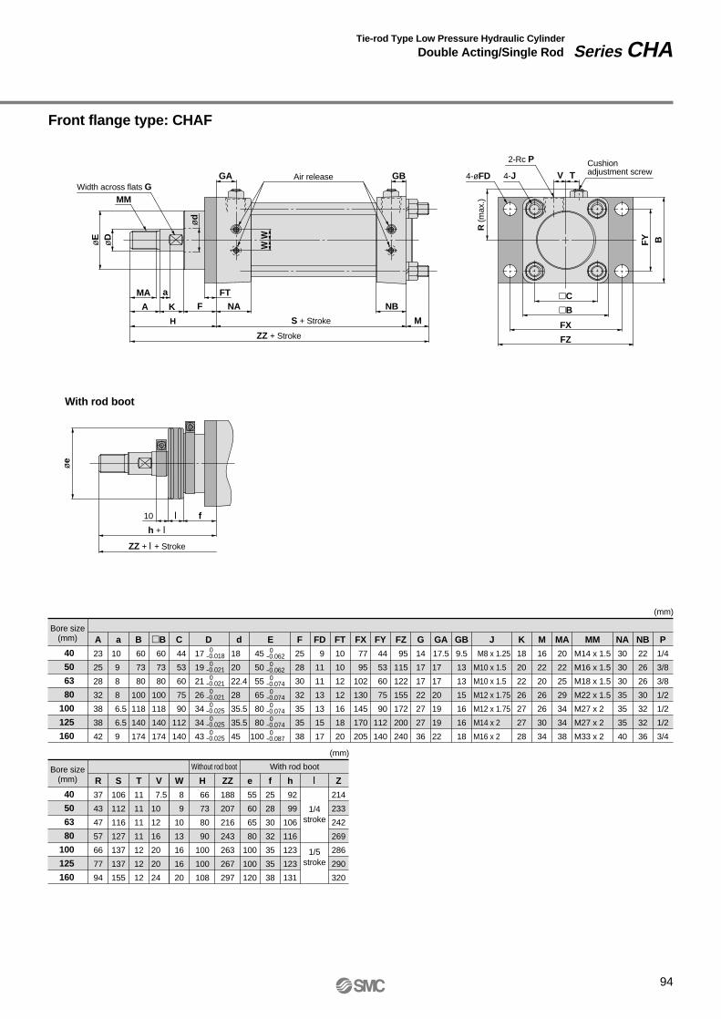
Front flange type: CHAF
94
Width across flats GMM
øE
øe
WW
R (m
ax.)
FY BøD
ød
GA GB
MA a FT
A K F NA NB
MH S + Stroke
ZZ + Stroke
Air release 4-øFD 4-J
2-Rc P
V TCushionadjustment screw
C
B
FX
FZ
10 fl
h + l
ZZ + l + Stroke
With rod boot
Tie-rod Type Low Pressure Hydraulic Cylinder
Double Acting/Single Rod Series CHA
Bore size(mm) A
23
25
28
32
38
38
42
a
10
9
8
8
6.5
6.5
9
d
18
20
22.4
28
35.5
35.5
45
B
60
73
80
100
118
140
174
B
60
73
80
100
118
140
174
C
44
53
60
75
90
112
140
F
25
28
30
32
35
35
38
FD
9
11
11
13
13
15
17
FT
10
10
12
12
16
18
20
GB
9.5
13
13
15
16
16
18
FZ
95
115
122
155
172
200
240
FY
44
53
60
75
90
112
140
FX
77
95
102
130
145
170
205
G
14
17
17
22
27
27
36
GA
17.5
17
17
20
19
19
22
J
M8 x 1.25
M10 x 1.5
M10 x 1.5
M12 x 1.75
M12 x 1.75
M14 x 2
M16 x 2
K
18
20
22
26
27
27
28
MM
M14 x 1.5
M16 x 1.5
M18 x 1.5
M22 x 1.5
M27 x 2
M27 x 2
M33 x 2
MA
20
22
25
29
34
34
38
NB
22
26
26
30
32
32
36
P
1/4
3/8
3/8
1/2
1/2
1/2
3/4
NA
30
30
30
35
35
35
40
M
16
22
20
26
26
30
34
(mm)
E
45
50
55
65
80
80
100
0-0.062 0-0.062 0-0.074 0-0.074 0-0.074 0-0.074 0-0.087
D
17
19
21
26
34
34
43
0-0.018 0-0.021 0-0.021 0-0.021 0-0.025 0-0.025 0-0.025
Bore size(mm) S
106
112
116
127
137
137
155
R
37
43
47
57
66
77
94
T
11
11
11
11
12
12
12
V
7.5
10
12
16
20
20
24
W
8
9
10
13
16
16
20
(mm)
H
66
73
80
90
100
100
108
ZZ
188
207
216
243
263
267
297
Z
214
233
242
269
286
290
320
e
55
60
65
80
100
100
120
f
25
28
30
32
35
35
38
h
92
99
106
116
123
123
131
l
1/4stroke
1/5stroke
Without rod boot With rod boot
40
50
63
80
100
125
160
40
50
63
80
100
125
160

Rear flange type: CHAG
95
Series CHA
øD
øe
øE
MM
Width across flats GGA4-J Air release GB
WW
MA
A K
H
NA
S + Stroke
ZZ + Stroke
NBC
B
FX
FZ
F
Ma
V T2-Rc P
4-J4-øFD
R (m
ax.)
Cushionadjustment screw
FY B
10 l f
h + l
ZZ + l + Stroke
With rod boot
FT
ød
Dimensions
Bore size (mm) A
23
25
28
32
38
38
42
a
10
9
8
8
6.5
6.5
9
d
18
20
22.4
28
35.5
35.5
45
B
60
73
80
100
118
140
174
C
44
53
60
75
90
112
140
F
25
28
30
32
35
35
38
FD
9
11
11
13
13
15
17
FT
10
10
12
12
16
18
20
FX
77
95
102
130
145
170
205
G
14
17
17
22
27
27
36
FZ
95
115
122
155
172
200
240
FY
44
53
60
75
90
112
140
GA
17.5
17
17
20
19
19
22
GB
9.5
13
13
15
16
16
18
K
18
20
22
26
27
27
28
M
16
22
20
26
26
30
34
MM
M14 x 1.5
M16 x 1.5
M18 x 1.5
M22 x 1.5
M27 x 2
M27 x 2
M33 x 2
NA
30
30
30
35
35
35
40
P
1/4
3/8
3/8
1/2
1/2
1/2
3/4
R
37
43
47
57
66
77
94
NB
22
26
26
30
32
32
36
MA
20
22
25
29
34
34
38
J
M8 x 1.25
M10 x 1.5
M10 x 1.5
M12 x 1.75
M12 x 1.75
M14 x 2
M16 x 2
(mm)
E
45
50
55
65
80
80
100
0-0.062 0-0.062 0-0.074 0-0.074 0-0.074 0-0.074 0-0.087
D
17
19
21
26
34
34
43
0-0.018 0-0.021 0-0.021 0-0.021 0-0.025 0-0.025 0-0.025
Bore size (mm) S
106
112
116
127
137
137
155
T
11
11
11
11
12
12
12
V
7.5
10
12
16
20
20
24
W
8
9
10
13
16
16
20
(mm)
H
66
73
80
90
100
100
108
ZZ
182
195
208
229
253
255
283
Z
208
221
234
255
276
278
306
e
55
60
65
80
100
100
120
f
25
28
30
32
35
35
38
h
92
99
106
116
123
123
131
l
1/4stroke
1/5stroke
Without rod boot With rod boot
40
50
63
80
100
125
160
40
50
63
80
100
125
160

Single clevis type: CHAC
96
h + l
Z + l + Stroke
ZZ + l + Stroke
With rod boot
10 fl
øe
V T2-Rc PCushionadjustment screw
øCDH9
CX ±0.3
C
B
R (
max
.)
MA
A K F NA NB U
a
H
RR
S + Stroke
Z + Stroke
ZZ + Stroke
GA GB4-J Air release
W
ød
øDøE
W
MM
Width across flats G
Tie-rod Type Low Pressure Hydraulic Cylinder
Double Acting/Single Rod Series CHA
L 0 -0.3
Bore size (mm) A
23
25
28
32
38
38
42
a
10
9
8
8
6.5
6.5
9
CX
21
23
27
31
35
41
54
B
60
73
80
100
118
140
174
C
44
53
60
75
90
112
140
d
18
20
22.4
28
35.5
35.5
45
D
17
19
21
26
34
34
43
CDH9
12
14
16
18
20
22
25
E
45
50
55
65
80
80
100
F
25
28
30
32
35
35
38
GB
9.5
13
13
15
16
16
18
GA
17.5
17
17
20
19
19
22
G
14
17
17
22
27
27
36
J
M8 x 1.25
M10 x 1.5
M10 x 1.5
M12 x 1.75
M12 x 1.75
M14 x 2
M16 x 2
MA
20
22
25
29
34
34
38
L
32
35
40
45
50
55
65
K
18
20
22
26
27
27
28
NB
22
26
26
30
32
32
36
P
1/4
3/8
3/8
1/2
1/2
1/2
3/4
NA
30
30
30
35
35
35
40
RR
15
18
20
22
24
26
30
S
106
112
116
127
137
137
155
R
37
43
47
57
66
77
94
MM
M14 x 1.5
M16 x 1.5
M18 x 1.5
M22 x 1.5
M27 x 2
M27 x 2
M33 x 2
(mm)
0-0.062 0-0.062 0-0.074 0-0.074 0-0.074 0-0.074 0-0.087
0-0.018 0-0.021 0-0.021 0-0.021 0-0.025 0-0.025 0-0.025
Bore size (mm) T
11
11
11
11
12
12
12
U
18
21
23
26
30
30
40
V
7.5
10
12
16
20
20
24
W
8
9
10
13
16
16
20
(mm)
H
66
73
80
90
100
100
108
Z
204
220
236
262
287
292
328
ZZ
219
238
258
284
311
318
358
Z
230
246
262
288
310
315
351
ZZ
245
264
284
310
334
341
381
e
55
60
65
80
100
100
120
f
25
28
30
32
35
35
38
h
92
99
106
116
123
123
131
l
1/4stroke
1/5stroke
Without rod boot With rod boot
+0.043 0+0.043 0+0.043 0+0.043 0+0.052 0+0.052 0+0.052 0
40
50
63
80
100
125
160
40
50
63
80
100
125
160

Double clevis type: CHAD
97
øe
10 l f
h + l
Z + l + Stroke
ZZ + l + Stroke
With rod boot
2-Rc PCushionadjustment screwV T
R (m
ax.)
CX ±0.3
C
B
MA
A K
H
F NA NB U
RR
a
L 0 -0.3S + Stroke
Z + Stroke
ZZ + Stroke
øCDH9
GBAir release
W
ød
øDøE
W
GA4-J
Width across flats G
MM
Series CHA
Dimensions
Bore size(mm) A
23
25
28
32
38
38
42
a
10
9
8
8
6.5
6.5
9
CX
22
24
28
32
36
42
55
B
60
73
80
100
118
140
174
C
44
53
60
75
90
112
140
d
18
20
22.4
28
35.5
35.5
45
D
17
19
21
26
34
34
43
CDH9
ø12H9
ø14H9
ø16H9
ø18H9
ø20H9
ø22H9
ø25H9
E
45
50
55
65
80
80
100
F
25
28
30
32
35
35
38
GB
11
13
13
15
16
16
18
GA
17.5
17
17
20
19
19
22
G
14
17
17
22
27
27
36
J
M8 x 1.25
M10 x 1.5
M10 x 1.5
M12 x 1.75
M12 x 1.75
M14 x 2
M16 x 2
MA
20
22
25
29
34
34
38
L
32
35
40
45
50
55
65
K
18
20
22
26
27
27
28
NB
22
26
26
30
32
32
36
P
1/4
3/8
3/8
1/2
1/2
1/2
3/4
NA
30
30
30
35
35
35
40
RR
15
18
20
22
24
26
30
S
106
112
116
127
137
137
155
R
37
43
47
57
66
77
94
MM
M14 x 1.5
M16 x 1.5
M18 x 1.5
M22 x 1.5
M27 x 2
M27 x 2
M33 x 2
(mm)
0-0.062 0-0.062 0-0.074 0-0.074 0-0.074 0-0.074 0-0.087
0-0.018 0-0.021 0-0.021 0-0.021 0-0.025 0-0.025 0-0.025
Bore size(mm) T
11
11
11
11
12
12
12
U
18
21
23
26
30
30
40
V
7.5
10
12
16
20
20
24
W
8
9
10
13
16
16
20
(mm)
H
66
73
80
90
100
100
108
Z
204
220
236
262
287
292
328
ZZ
219
238
258
284
311
318
358
Z
230
246
262
288
310
315
351
ZZ
245
264
284
310
334
341
381
e
55
60
65
80
100
100
120
f
25
28
30
32
35
35
38
h
92
99
106
116
123
123
131
l
1/4stroke
1/5stroke
Without rod boot With rod boot
+0.043 0+0.043 0+0.043 0+0.043 0+0.052 0+0.052 0+0.052 0
40
50
63
80
100
125
160
40
50
63
80
100
125
160

Center trunnion type: CHAT
98
MM
WWø
DøE
GA TTAir release GB TVAir release
Z + 1/2 stroke2-Rc P
Cushion adjustment screw4-J
øT
De8
TY
øe
10 l f
h + l
ZZ + l + Stroke
Z + l + 1/2 stroke
MA a M
A K
H S + Stroke
ZZ + Stroke
F NA
M
NBB
TZ
C
TR
R (
max
.)
ød
With rod boot
Width across flats G
Tie-rod Type Low Pressure Hydraulic Cylinder
Double Acting/Single Rod Series CHA
TX 0 –0.5
Bore size(mm) A
23
25
28
32
38
38
42
a
10
9
8
8
6.5
6.5
9
d
18
20
22.4
28
35.5
35.5
45
B
60
73
80
100
118
140
174
C
44
53
60
75
90
112
140
F
25
28
30
32
35
35
38
G
14
17
17
22
27
27
36
GA
17.5
17
17
20
19
19
22
GB
9.5
13
13
15
16
16
18
K
18
20
22
26
27
27
28
M
10
10
10
13
13
15
17
MA
20
22
25
29
34
34
38
NA
30
30
30
35
35
35
40
NB
22
26
26
30
32
32
36
S
106
112
116
127
137
137
155
T
11
11
11
11
12
12
12
R
37
43
47
57
66
77
94
Tde8
15
15
15
25
32
32
36
P
1/4
3/8
3/8
1/2
1/2
1/2
3/4
J
M8 x 1.25
M10 x 1.5
M10 x 1.5
M12 x 1.75
M12 x 1.75
M14 x 2
M16 x 2
MM
M14 x 1.5
M16 x 1.5
M18 x 1.5
M22 x 1.5
M27 x 2
M27 x 2
M33 x 2
(mm)
E
45
50
55
65
80
80
100
0 -0.062 0 -0.062 0 -0.074 0 -0.074 0 -0.074 0 -0.074 0 -0.087
D
17
19
21
26
34
34
43
0-0.018 0-0.021 0-0.021 0-0.021 0-0.025 0-0.025 0-0.025
Bore size(mm) W
8
9
10
13
16
16
20
H
66
73
80
90
100
100
108
Z
123
131
140
156
170
170
187.5
TX
70
83
90
112
140
170
212
TT
24
26
26
36
42
42
52
TR
R0.5
R0.5
R0.5
R2.5
R2.5
R2.5
R2.5
TY
65
78
86
106
130
162
200
TZ
95
108
115
162
204
234
284
V
7.5
10
12
16
20
20
24
ZZ
182
195
206
230
250
252
280
e
55
60
65
80
100
100
120
f
25
28
30
32
35
35
38
h
92
99
106
116
123
123
131
l Z
149
157
166
182
193
193
210.5
ZZ
208
221
232
256
273
275
303
(mm)
-0.032-0.059-0.032-0.059-0.032-0.059-0.040-0.073-0.050-0.089-0.050-0.089-0.050-0.089
1/4stroke
1/5 stroke
Without rod boot With rod boot
40
50
63
80
100
125
160
40
50
63
80
100
125
160

Front trunnion type: CHAU
99
Series CHA
Z
GBGBTT V TWidth across flats G
MM
øD
øe
øE
Z + l
h + l
ZZ + l + Stroke
10 l f
MA a
A K
H MS + Stroke
ZZ + Stroke
F NA NBB
TZ
C
WW
2-Rc PCushion adjustment screw4-JAir release
TR
R (
max
.)
TY
øT
De8
ød
Dimensions
TX 0 –0.5
Bore size(mm) A
23
25
28
32
38
38
42
a
10
9
8
8
6.5
6.5
9
d
18
20
22.4
28
35.5
35.5
45
B
60
73
80
100
118
140
174
C
44
53
60
75
90
112
140
F
25
28
30
32
35
35
38
G
14
17
17
22
27
27
36
GA
17.5
17
17
20
19
19
22
GB
9.5
13
13
15
16
16
18
K
18
20
22
26
27
27
28
M
10
16
16
13
13
15
17
MA
20
22
25
29
34
34
38
NA
30
30
30
35
35
35
40
NB
22
26
26
30
32
32
36
S
106
112
116
127
137
137
155
T
11
11
11
11
12
12
12
R
37
43
47
57
66
77
94
Tde8
15
15
15
25
32
32
36
P
1/4
3/8
3/8
1/2
1/2
1/2
3/4
J
M8 x 1.25
M10 x 1.5
M10 x 1.5
M12 x 1.75
M12 x 1.75
M14 x 2
M16 x 2
MM
M14 x 1.5
M16 x 1.5
M18 x 1.5
M22 x 1.5
M27 x 2
M27 x 2
M33 x 2
(mm)
E
45
50
55
65
80
80
100
0-0.062 0-0.062 0-0.074 0-0.074 0-0.074 0-0.074 0-0.087
D
17
19
21
26
34
34
43
0-0.018 0-0.021 0-0.021 0-0.021 0-0.025 0-0.025 0-0.025
Bore size(mm) W
8
9
10
13
16
16
20
H
66
73
80
90
100
100
108
Z
58
65
72
75
83
83
89
TX
70
83
90
112
140
170
212
TY
60
73
80
100
118
140
174
TR
R0.5
R0.5
R0.5
R2.5
R2.5
R2.5
R2.5
TT
16
16
16
30
34
34
38
TZ
95
108
115
162
204
234
284
V
7.5
10
12
16
20
20
24
ZZ
182
201
212
230
250
252
280
e
55
60
65
80
100
100
120
f
25
28
30
32
35
35
38
h
92
99
106
116
123
123
131
l Z
84
91
98
101
106
106
112
ZZ
208
227
238
256
273
275
303
(mm)
-0.032-0.059-0.032-0.059-0.032-0.059-0.040-0.073-0.050-0.089-0.050-0.089-0.050-0.089
1/4stroke
1/5stroke
Without rod boot With rod boot
40
50
63
80
100
125
160
40
50
63
80
100
125
160
With rod boot
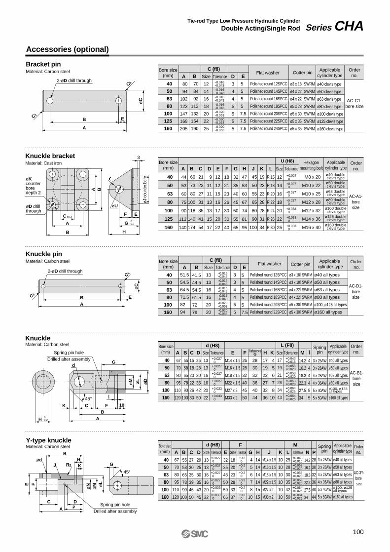
Accessories (optional)
Bracket pinMaterial: Carbon steel
Knuckle bracketMaterial: Cast iron
2-øD drill through
B
A
E
øC
C1
C1
3
øKcounterboredepth 2
øD drillthrough
C ±0.3
G A
øU
F
H
E
A B
øJ c
ount
er b
oreL
B
Knuckle pinMaterial: Carbon steel
KnuckleMaterial: Carbon steel
2-øD drill through
C1
C1
B E
A
øC
H 0–0.2
K C FB
A
10
l
Spring pin holeDrilled after assembly
dG
øM øL
øD
45°
Y-type knuckleMaterial: Carbon steel
ødB
HKJ
E
øN
øM ø
LF
R2
C
G
D
A
45°
Bore size(mm)
40
50
63
80
100
125
160
40
50
63
80
100
125
160
40
50
63
80
100
160
A
80
94
102
123
147
169
205
B
70
84
92
113
132
154
190
Size
12
14
16
18
20
22
25
D
3
4
4
5
5
5
5
E
5
5
5
5
7.5
7.5
7.5
Tolerance-0.016-0.043-0.016-0.043-0.016-0.043-0.016-0.043-0.020-0.053-0.020-0.053-0.020-0.053
C (f8) Flat washer Cotter pin
Orderno.
AC-C1-bore size
Applicablecylinder type
Polished round 12SPCC
Polished round 14SPCC
Polished round 16SPCC
Polished round 18SPCC
Polished round 20SPCC
Polished round 22SPCC
Polished round 24SPCC
ø3 x 18l SWRM
ø4 x 22l SWRM
ø4 x 22l SWRM
ø5 x 28l SWRM
ø5 x 30l SWRM
ø5 x 35l SWRM
ø5 x 35l SWRM
ø40 clevis type
ø50 clevis type
ø63 clevis type
ø80 clevis type
ø100 clevis type
ø125 clevis type
ø160 clevis type
Bore size(mm)
Bore size(mm)
A
44
53
60
75
90
112
140
B
60
73
80
100
118
140
174
21
23
27
31
35
41
54
C F
18
21
23
26
30
30
40
12
12
15
16
17
20
22
E G
32
35
40
45
50
55
65
H
47
53
60
67
74
81
95
J
45
50
55
65
80
90
100
K
19
23
23
28
28
31
34
L
R 15
R 18
R 20
R 22
R 24
R 26
R 30
Size
12
14
16
18
20
22
25
Tolerance
9
11
11
13
13
15
17
D +0.027 0
+0.027 0
+0.027 0
+0.027 0
+0.033 0
+0.033 0
+0.033 0
Orderno.
AC-A1-boresize
Hexagonmounting bolt
U (H8)
M8 x 20
M10 x 22
M10 x 25
M12 x 28
M12 x 32
M14 x 36
M16 x 40
Applicablecylinder typeø40 doubleclevis typeø50 doubleclevis typeø63 doubleclevis typeø80 doubleclevis type
ø100 doubleclevis type
ø125 doubleclevis type
ø160 doubleclevis type
40
50
63
80
100
160
Bore size(mm)
40
50
63
80
100
160
Bore size(mm)
A
51.5
54.5
64.5
71.5
82
94
B
41.5
44.5
54.5
61.5
72
79
Size
13
13
16
16
20
20
D
3
3
4
4
5
5
E
5
5
5
5
5
7.5
Tolerance-0.016-0.043-0.016-0.043-0.016-0.043-0.016-0.043-0.020-0.053-0.020-0.053
C (f8) Order no.
AC-D1-boresize
Flat washer
Polished round 12SPCC
Polished round 14SPCC
Polished round 16SPCC
Polished round 18SPCC
Polished round 20SPCC
Polished round 22SPCC
Cotter pin
ø3 x 18l SWRM
ø3 x 18l SWRM
ø4 x 22l SWRM
ø4 x 22l SWRM
ø5 x 30l SWRM
ø5 x 30l SWRM
Applicable cylinder type
ø40 all types
ø50 all types
ø63 all types
ø80 all types
ø100, ø125 all types
ø160 all types
ReferenceG
28
30
32
36
40
44
Tolerance +0.027 0 +0.027 0 +0.027 0 +0.027 0 +0.033 0 +0.033 0
Orderno.
AC-B1-boresize
Springpin
3 x 25AW
3 x 28AW
4 x 28AW
4 x 36AW
5 x 40AW
5 x 50AW
Applicablecylinder type
ø40 all types
ø50 all types
ø63 all types
ø80 all types
ø160 all types
d (H8) L (F8)
67
70
80
95
110
120
A
55
58
65
78
90
100
B
15
18
20
22
26
30
C
25
28
30
35
42
50
D
4
5
6
7
8
10
K
17
19
22
27
32
36
H
14.2
16.2
18.3
22.3
27.5
34
M
26
28
32
40
45
50
F
M14 x 1.5
M16 x 1.5
M18 x 1.5
M22 x 1.5
M27 x 2
M33 x 2
E
13
13
16
16
20
22
Size
Tolerance
d (H8)
A B C D G L
F
E KJH N
M
Size
+0.043 +0.016 +0.053 +0.020 +0.053 +0.020 +0.053 +0.020 +0.064 +0.025 +0.064 +0.025
Tolerance
17
19
21
26
34
43
Size
4
4
4
4
5
5
l
67
70
80
95
110
120
55
58
65
78
90
100
27
30
35
39
46
50
13
13
16
16
20
22
32
35
43
50
59
66
18
20
23
28
33
37
4
5
6
7
8
10
14
14
14
14
15
15
10
10
10
10
10
10
25
28
30
35
42
50
14.2
16.2
18.3
22.3
27.5
34
M14 x 1.5
M16 x 1.5
M18 x 1.5
M22 x 1.5
M27 x 2
M33 x 2
29
25
30
35
43
45
+0.043 +0.016 +0.053 +0.020 +0.053 +0.020 +0.053 +0.020 +0.064 +0.025 +0.064 +0.025
+0.2 0 +0.2 0 +0.2 0 +0.2 0 +0.2 0 +0.2 0
+0.027 0 +0.027 0 +0.027 0 +0.027 0 +0.033 0 +0.033 0
Orderno.
AC-3Y-bore size
Applicablecylinder type
ø40 all types
ø50 all types
ø63 all types
ø80 all typesø100, ø125all types
ø160 all types
Tolerance ToleranceSize
ø100, ø125all types
Spring pin holeDrilled after assembly
3 x 25AW
3 x 28AW
4 x 28AW
4 x 36AW
5 x 40AW
5 x 50AW
SpringpinP
28
30
32
36
40
44
Tie-rod Type Low Pressure Hydraulic Cylinder
Double Acting/Single Rod Series CHA
100
0–0.3
P

Auto Switches: Proper Mounting Positions and Mounting Heights for Stroke End Detection
<Tie-rod mount type>
Reed switchesD-A5, D-A6D-A59W
Solid state switchesD-F5, D-J5, D-F5NTLD-F5W, D-J59WD-F5BAL, D-F5F
<Band mount type>
Reed switchD-A3
Solid state switchesD-G39, D-K39
Reed switchD-A44
Reed switchesD-B5, D-B6
A 33
A 49
A B33
12
36
49A
36
B
B
Approx. Hs
Approx. Hs
Appr
ox. H
tAp
prox
. Ht
Auto switch
Auto switch
G 1/2(applicable cable O.D. ø6.8 to ø9.6)
G 1/2(applicable cable O.D. ø6.8 to ø9.6)
3456
Approx. Hs
56
Approx. Hs
22.5
15
Auto switch
Auto switch
B
101
Series CHA
Auto Switch Specifications
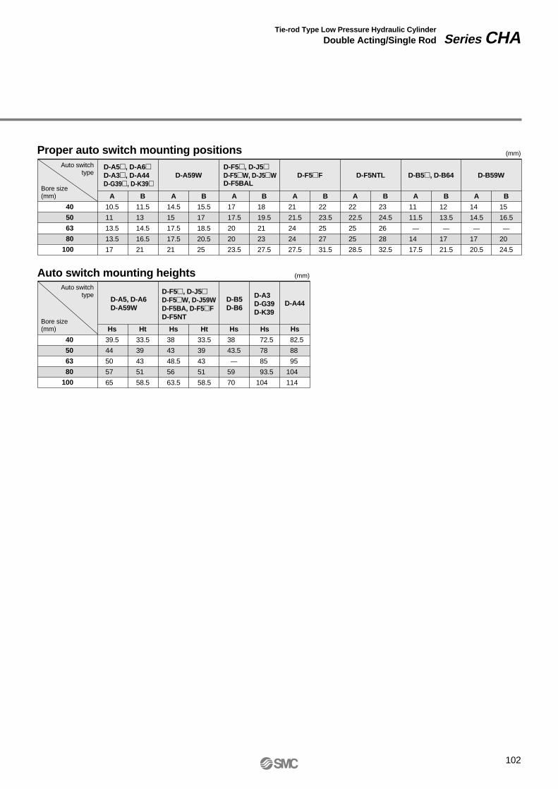
102
40
50
63
80
100
D-A5, D-A6D-A3, D-A44D-G39, D-K39
D-F5, D-J5D-F5W, D-J5WD-F5BAL
A
10.5
11
13.5
13.5
17
B
11.5
13
14.5
16.5
21
A
14.5
15
17.5
17.5
21
B
15.5
17
18.5
20.5
25
A
17
17.5
20
20
23.5
B
18
19.5
21
23
27.5
A
22
22.5
25
25
28.5
B
23
24.5
26
28
32.5
A
11
11.5
—
14
17.5
B
12
13.5
—
17
21.5
A
21
21.5
24
24
27.5
B
22
23.5
25
27
31.5
D-A59W D-F5NTLD-F5F D-B5, D-B64
A
14
14.5
—
17
20.5
B
15
16.5
—
20
24.5
D-B59W
Proper auto switch mounting positions
Auto switch mounting heights
Bore size(mm)
Auto switchtype
(mm)
(mm)
40
50
63
80
100
D-A5, D-A6D-A59W
D-B5D-B6
D-A3D-G39D-K39
Hs
39.5
44
50
57
65
Ht
33.5
39
43
51
58.5
Hs
38
43
48.5
56
63.5
Ht
33.5
39
43
51
58.5
Hs
38
43.5
—
59
70
Hs
72.5
78
85
93.5
104
Hs
82.5
88
95
104
114
D-F5, D-J5D-F5W, D-J59WD-F5BA, D-F5FD-F5NT
D-A44
Bore size(mm)
Auto switchtype
Tie-rod Type Low Pressure Hydraulic Cylinder
Double Acting/Single Rod Series CHA

How to Order
2 pcs.1 pc.3 pcs.
"n" pcs.
NilS3n
Number of auto switches
Without auto switchNil
Auto switch type
Mounting types
Built-in magnet
103
Tie-rod Type Low Pressure Hydraulic CylinderDouble Acting/Double Rod
Series CHAWø40, ø50, ø63, ø80, ø100, ø125, ø1603.5MPa
CHAW 40 100LLWith Auto Switch
BLFTU
Basic typeAxial foot typeFront flange typeCenter trunnion typeFront trunnion type
Cylinder optionNilNRH
Both sidesWithout cushion
With front cushionWith rear cushion
Cushion
CHDAW 40 100 A34Cylinder stroke (mm)Refer to the standard stroke table on page 104.
Aluminum alloySteel tube
NilF
Tube material
Bore size40506380
100
40mm 50mm 63mm 80mm100mm A
lum
inum
tube
Bore size40506380
100125160
40mm 50mm 63mm 80mm100mm125mm160mm
Alu
min
um tu
be
Ste
el tu
be
∗ Select applicable auto switch models from the table below.
Applicable Auto Switches:
Typ
e Electricalentry
Indi
cato
rlig
ht
3-wire (NPN equiv.)
Load voltage
——
ACDC
Lead wire length (m)∗
0.5(Nil)
3 (L)
5 (Z)
IC circuit
—
IC circuit
—
IC circuit
—
IC circuit—
IC circuit
—
IC circuit
—
Applicableload
100V200V
100V200V
100V200V
Yes
Yes
Yes
Diagnostic indication (2-color display)
Diagnostic indication(2-color display)
With diagnostic output (2-color display)
Latch type with diagnostic output(2-color display)
With timerWater resistant (2-color display)
No 2-wire
So
lid s
tate
sw
itch
Ree
d s
witc
h
A56A53
A54
A67A64———
A59WF59F5P
J51
J59——
F59WF5PWJ59WF5BAF5NTF59F
F5LF
—
—
Relay, PLC
24V
24V
—
— —
—
24V
Grommet
Grommet
Grommet
Grommet
DIN terminal
Terminalconduit
Terminalconduit
Wiring(output)
Special function
—B53
B54
—B64A33A34A44
B59W——
—
—G39K39——————
—
———
————
———
——
—
——————
——
Auto switch type
—
—200V or less
—
—
—PLC
Relay, PLC
PLCRelay, PLC
PLC
Relay, PLC
3-wire (NPN)3-wire (PNP)
2-wire
3-wire (NPN)2-wire
3-wire (NPN)3-wire (PNP)
2-wire
3-wire (NPN)
4-wire (NPN)
Refer to "Auto Switch Guide" CAT.E274-A for further details on each auto switch.Refer to pages 117 and 118 for auto switch circuit diagrams.
Tie-rodmount
Bandmount
5V12V
12V
5V, 12V5V, 12V
12V
5V, 12V
—
12V5V, 12V
12V
5V, 12V
12V
5V, 12V
—
∗ Lead wire length symbols: 0.5m ......... Nil (Example) A533m ............ L (Example) A53L5m ............ Z (Example) A53Z
Note) • Solid state auto switches marked "" are produced upon receipt of order. • Types D-B53, D-B54, D-B64 and D-B59W cannot be mounted on bore size ø63 cylinders.
Part nos. for cylinders with built-in magnetsIn the case of cylinders with built-in magnets but no auto switches, do not incicate any auto switch type symbol.(Example) CHDAWB50-100

104
Action
Fluid
Nominal pressure
Proof pressure
Maximum allowable pressure
Minimum operating pressure
Ambient and fluid temperature
Piston speed
Cushion
Thread tolerance
Double acting/Double rod
Hydraulic fluid
3.5MPa
5.0MPa
3.5MPa
0.25MPa
Without auto switch: –10° to 80°CWith auto switch: –10° to 60°C
8 to 300mm/s
Cushion seal Note 1)
JIS class 2
Bore size (mm)
40
50
63
80
100
125
160
Standard strokes (mm)
25 to 800
25 to 800
25 to 800
25 to 1000
25 to 1000
25 to 1000
50 to 1200
Bore sizes (mm)
40, 50, 63, 80, 100
40, 50, 63, 80, 100, 125, 160
Specifications
Standard Strokes
Model
Models
CHAW
CHAFW
Tube material
Aluminum alloy
Steel
Stroke length tolerance
Mounting type
JIS symbol
• LightPrinciple parts are light weight aluminum alloy.
• Easy position detection with auto switchesAluminum cylinder sizes ø40 to ø100 are auto switch capable for easy stroke position detection.
• Smooth cushioningCushioning nearly equal to a shock absorber is achieved with a unique cushion ring configuration and cushion seal design.
Refer to page 100.
Accessories (Optional)
Bore size (mm)
40506380
100125160
Effective cushion stroke (mm)
15151720202022
Cushion Strokes (for Front & Rear)
∗ Maximum ambient temperature:Nylon tarpaulin (60°C)Neoprene cloth (110°C)
Knuckle bracket, Single knuckleDouble knuckle, Bracket pinKnuckle pinRod boot ∗
( )Nylon tarpaulinNeoprene cloth
Note) Refer to the stroke selection Table in Technical Data 2, starting with page 123 to determine stroke limitation depending on the type of mounting brackets that will be used. Then make sure your selection.
40506380
100
BD1-04MBD1-05MBD1-06MBD1-08MBD1-10M
BA-04BA-05
—BA-08BA-10
BT-04BT-06BT-06BT-08BT-08
Auto Switch Mounting Bracket Part Nos.
Bore size (mm)
Auto switch types
D-A3, D-A44D-G39, D-K39
D-A5, D-A6, D-A59W, D-F5, D-J5D-F5W, D-J59W, D-F5NT, D-F5BA, D-F5FD-B5, D-B6
+0.80
+1.00
+1.250
+1.40
+1.80
to 100mm mm, 100 to 250mm mm, 250 to 630mm mm
630 to 1000mm mm, 1000 to 1200mm mm
Basic type (B), Axial foot type (L), Front flange type (F),Rear flange type (G), Single clevis type (C), Double clevis type (D), Center trunnion type (T), Front trunnion type (U)
Note 1) Insert type with check mechanism.
∗ Refer to page 136 for definitions of terms related to pressure.
Tie-rod Type Low Pressure Hydraulic Cylinder
Double Acting/Double Rod Series CHAW
Hydraulic Fluid Compatibility
Hydraulic fluid Compatibility
Compatible
Compatible
Compatible
Not compatible
Not compatible
Standard mineral hydraulic fluid
W/O hydraulic fluid
O/W hydraulic fluid
Water/Glycol hydraulic fluid
Phosphate hydraulic fluid

105
Minimum Strokes for Auto Switch Mountingn: Numbers of auto switched
Series CHAW
Auto switchtypes
D-A5, D-A6D-F5, D-J5
D-A3D-G39D-K39
D-A44
D-F5W, D-J59WD-F5BAD-F5FD-F5NT
D-A59W
D-B5, D-B6
Center trunnion type
90
100
120 + 50n = 4, 6, 8 …
(n – 4)2
(n – 2)2
120
120
120
120 + 50n = 2, 4, 6, 8 …
n = 4, 8, 12, 16 …
ø100
120
120
140
120
120 + 55n = 4, 8, 12, 16 …
(n – 4)2
120 + 55n = 4, 8, 12, 16 …
(n – 4)2
140 + 55(n – 4)
2
ø80
110
110
130
110
110 + 55n = 4, 8, 12, 16 …
(n – 4)2
110 + 55n = 4, 8, 12, 16 …
(n – 4)2
130 + 55n = 4, 8, 12, 16 …
(n – 4)2
90 + 30 (n – 2)n = 2, 4, 6, 8 …
100 + 100 (n – 2) n = 4, 6, 8 …
Mounting bracketsother than
center trunnion
10
15
20
15
10
15
75
35
10
10
10 + 55n = 2, 4, 6, 8 …
(n – 2)2
100 + 100n = 2, 3, 4 …
20 + 55n = 2, 4, 6, 8 …
(n – 2)2
15 + 55n = 2, 4, 6, 8 …
(n – 2)2
15 + 50n = 2, 4, 6, 8 …
(n – 2)2
75 + 50 (n – 2)n = 2, 3, 4 …
35 + 30 (n – 2)n = 2, 3, 4 …
35 + 30 (n – 2)n = 2, 3, 4 …
55 + 50 (n – 2)n = 2, 3, 4 …
35
55
ø40 and ø50
100
100
120
90
90
100
90
75
75
75
100 + 55n = 4, 8, 12, 16 …
(n – 4)2
100 + 55n = 4, 8,1 2, 16 …
(n – 4)2
120 + 55n = 4, 8, 12, 16 …
(n – 4)2
90 + 50n = 4, 8, 12, 16 …
(n – 4)2
(n – 2)290 + 50
n = 2, 4, 6, 8 …
75 + 30 (n – 2)n = 2, 4, 6, 8 …
75 + 30 (n – 2)n = 2, 4, 6, 8 …
75 + 50 (n – 2)n = 2, 4, 6, 8 …
75
75
ø63
100
100
120
100
—
—
—
80
80
80
—
100 + 55n = 4, 8, 12, 16 …
(n – 4)2
100 + 55n = 4, 8, 12, 16 …
(n – 4)2
120 + 55n = 4, 8, 12, 16 …
(n – 4)2
80 + 30 (n – 2)n = 2, 4, 6, 8 …
80 + 30 (n – 2)n = 2, 4, 6, 8 …
80 + 50 (n – 2)n = 2, 4, 6, 8 …
—
80
80
90
90
90
90
90 + 30 (n – 2)n = 2, 4, 6, 8 …
90 + 50 (n – 2)n = 2, 4, 6, 8 …
2 pc
s."n
" pc
s.2
pcs.
"n"
pcs.
2 pc
s."n
" pc
s.
Number ofauto switches
1 or 2 pcs.(different sides/same side)
"n" pcs. (same side)
2 pcs.(different sides/same side)
"n" pcs. (same side)
1 pc.
1 or 2 pcs.(different sides/same side)
"n" pcs. (same side)
1 pc.
1 pc.
Different sides
Same side
Different sides
1 pc.
Same side
Different sides
Different sides
Same side
Same side
Different sides
Same side
Different sides
Same side
120
120
12090 —
D-B59W
20
75
15
75 + 50 (n – 2)n = 2, 3, 4 …
90 + 50 (n – 2)n = 2, 4, 6 …
120 + 50 (n – 2)n = 2, 4, 6, 8 …
20 + 50n = 2 ,4 ,6, 8 …
90
90
—
—
—
—
2 pc
s."n
" pc
s.
1 pc.
Different sides
Same side
Different sides
Same side
(n – 2)2
(n – 2)2
90 + 50n = 4, 8, 12, 16 …
(n – 4)2 120 + 50
n = 4, 8, 12, 16 …
(n – 4)2
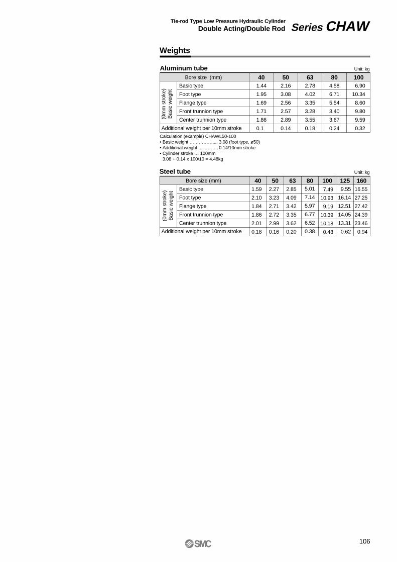
Aluminum tubeBore size (mm)
Additional weight per 10mm stroke
Unit: kg
Basic type
Foot type
Flange type
Front trunnion type
Center trunnion type(0m
m s
trok
e)B
asic
wei
ght
40 50 63 80 100
Steel tubeBore size (mm)
Additional weight per 10mm stroke
Unit: kg
Basic type
Foot type
Flange type
Front trunnion type
Center trunnion type
(0m
m s
trok
e)B
asic
wei
ght
40 50 63 80 100 125 160
Calculation (example) CHAWL50-100• Basic weight …………….... 3.08 (foot type, ø50)• Additional weight …………. 0.14/10mm stroke• Cylinder stroke … 100mm
3.08 + 0.14 x 100/10 = 4.48kg
1.44
1.95
1.69
1.71
1.86
0.1
2.16
3.08
2.56
2.57
2.89
0.14
2.78
4.02
3.35
3.28
3.55
0.18
4.58
6.71
5.54
3.40
3.67
0.24
6.90
10.34
8.60
9.80
9.59
0.32
1.59
2.10
1.84
1.86
2.01
0.18
2.27
3.23
2.71
2.72
2.99
0.16
2.85
4.09
3.42
3.35
3.62
0.20
5.01
7.14
5.97
6.77
6.52
0.38
7.49
10.93
9.19
10.39
10.18
0.48
9.55
16.14
12.51
14.05
13.31
0.62
16.55
27.25
27.42
24.39
23.46
0.94
Weights
Tie-rod Type Low Pressure Hydraulic Cylinder
Double Acting/Double Rod Series CHAW
106

No.
1
2
3
4
5
6
7
8
9
10
11
12
13
14
15
16
17
18
19
20
21
22
Description
Parts list Replacement parts: Seal kits
Rod cover
Cylinder tube
Piston rod A
Piston rod B
Piston
Cushion ring
Needle valve
Bushing
Tie-rod
Tie-rod washer
Spring pin
Needle valve nut
Tie-rod nut
Air release valve
Check ball
Wiper ring
Rod seal
Piston seal
Needle valve seal
Cylinder tube gasket
Piston gasket
Cushion seal
Material
Aluminum alloy
Aluminum alloy
Carbon steel
Carbon steel
Carbon steel
Aluminum alloy
Rolled steel
Rolled steel
Lead bronze
Carbon steel
Steel wire
Rolled steel
Carbon steel
Carbon steel
Alloy steel
Bearing steel
NBR
NBR
NBR
NBR
NBR
NBR
—
Note
70% flat black
Hard anodized
Hard chromium electronplated
Hard chromium electronplated
Bore size (mm) Seal kit no.
CHAW40-PS
CHAW50-PS
CHAW63-PS
CHAW80-PS
CHAW100-PS
CHAW125-PS
CHAW160-PS
Kit components
Nos. 16 through 20 and 22from the chart at left
40
50
63
80
100
125
160
ø40
Construction
∗ Seal kits consist of items of 16 through 20 and 22, and can be ordered by using the seal kit number for each bore size.
Series CHAW
107

Basic type: CHAWB
108
Bore size(mm)
40
50
63
80
100
125
160
A
23
25
28
32
38
38
42
a
10
9
8
8
6.5
6.5
9
d
18
20
22.4
28
35.5
35.5
45
B
60
73
80
100
118
140
174
C
44
53
60
75
90
112
140
F
25
28
30
32
35
35
38
G
14
17
17
22
27
27
36
GA
17.5
17
17
20
19
19
22
K
18
20
22
26
27
27
28
M
13
16
16
19
21
24
27
MA
20
22
25
29
34
34
38
NA
30
30
30
35
35
35
40
R
37
43
47
57
66
77
94
S
114
116
120
132
140
140
159
H
66
73
80
90
100
100
108
ZZ
246
262
280
312
340
340
375
V
7.5
10
12
16
20
20
24
W
8
9
10
13
16
16
20
T
11
11
11
11
12
12
12
P
1/4
3/8
3/8
1/2
1/2
1/2
3/4
J
M8 x 1.25
M10 x 1.5
M10 x 1.5
M12 x 1.75
M12 x 1.75
M14 x 2
M16 x 2
MM
M14 x 1.5
M16 x 1.5
M18 x 1.5
M22 x 1.5
M27 x 2
M27 x 2
M33 x 2
(mm)
E
45
50
55
65
80
80
100
0 -0.062 0 -0.062 0 -0.074 0 -0.074 0 -0.074 0 -0.074 0-0.087
Dimensions
D
17
19
21
26
34
34
43
0 -0.018 0 -0.021 0 -0.021 0 -0.021 0 -0.025 0 -0.025 0 -0.025
MA
MM
Width across flats G
A K
H
F NA NA F K A
M MAaa M
H + StrokeS + Stroke
ZZ + 2 strokes
4-J GA
øE
øD W
W
ød
Air release GA
MM
Width across flats G
øDød
øE
R (m
ax.)
2-Rc PCushion adjustment screw
T T
V V
C
B
Tie-rod Type Low Pressure Hydraulic Cylinder
Double Acting/Double Rod Series CHAW

Foot type: CHAWL
109
Series CHAW
Dimensions
Bore size(mm)
40
50
63
80
100
125
160
A
23
25
28
32
38
38
42
a
10
9
8
8
6.5
6.5
9
d
18
20
22.4
28
35.5
35.5
45
B
60
73
80
100
118
140
174
B
60
73
80
100
118
140
174
C
44
53
60
75
90
112
140
F
25
28
30
32
35
35
38
G
14
17
17
22
27
27
36
GA
17.5
17
17
20
19
19
22
K
18
20
22
26
27
27
28
M
10
12
12
14
14
16
18
MA
20
22
25
29
34
34
38
NA
30
30
30
35
35
35
40
R
37
43
47
57
66
77
94
P
1/4
3/8
3/8
1/2
1/2
1/2
3/4
S
114
116
120
132
140
140
159
X
27
30
37
40
47
55
60
V
7.5
10
12
16
20
20
24
W
8
9
10
13
16
16
20
T
11
11
11
11
12
12
12
J
M8 x 1.25
M10 x 1.5
M10 x 1.5
M12 x 1.75
M12 x 1.75
M14 x 2
M16 x 2
MM
M14 x 1.5
M16 x 1.5
M18 x 1.5
M22 x 1.5
M27 x 2
M27 x 2
M33 x 2
(mm)
E
45
50
55
65
80
80
100
0 -0.062 0 -0.062 0 -0.074 0 -0.074 0 -0.074 0 -0.074 0 -0.087
D
17
19
21
26
34
34
43
0 -0.018 0 -0.021 0 -0.021 0 -0.021 0 -0.025 0 -0.025 0 -0.025
Bore size(mm)
40
50
63
80
100
125
160
H
66
73
80
90
100
100
108
ZZ
246
262
280
312
340
340
375
LT
8
10
10
12
14
16
18
LX
44
53
60
75
90
112
140
LY
77
88.5
95
115
139
170
197
LH
47
52
55
65
80
100
110
LD
9
11
11
13
13
15
17
LS
168
176
194
212
234
250
279
Y
8
10
10
13
13
15
20
(mm)
WW
HK F
Y X YXLXB
S + Stroke
LS + Stroke
ZZ + 2 strokes
GA
NA NA
AMA a
H + Stroke
FGA AMAa
ød
ød
øD øEøDøE
MMMM
T T
V V2-Rc P Cushion
adjustment screw4-J
R (m
ax.)
LH
±0.
2
C
B
LY
Air release
4-øLD
LTLT
Width across flats GWidth across flats G

Front flange type: CHAWF
110
Bore size (mm)
40
50
63
80
100
125
160
A
23
25
28
32
38
38
42
a
10
9
8
8
6.5
6.5
9
d
18
20
22.4
28
35.5
35.5
45
B
60
73
80
100
118
140
174
B
60
73
80
100
118
140
174
C
44
53
60
75
90
112
140
F
25
28
30
32
35
35
38
G
14
17
17
22
27
27
36
GA
17.5
17
17
20
19
19
22
K
18
20
22
26
27
27
28
M
16
22
20
26
26
30
34
MA
20
22
25
29
34
34
38
P
1/4
3/8
3/8
1/2
1/2
1/2
3/4
R
37
43
47
57
66
77
94
W
8
9
10
13
16
16
20
FD
9
11
11
13
13
15
17
T
11
11
11
11
12
12
12
V
7.5
10
12
16
20
20
24
S
114
116
120
132
140
140
159
NA
30
30
30
35
35
35
40
J
M8 x 1.25
M10 x 1.5
M10 x 1.5
M12 x 1.75
M12 x 1.75
M14 x 2
M16 x 2
MM
M14 x 1.5
M16 x 1.5
M18 x 1.5
M22 x 1.5
M27 x 2
M27 x 2
M33 x 2
(mm)
E
45
50
55
65
80
80
100
0 -0.062 0 -0.062 0 -0.074 0 -0.074 0 -0.074 0 -0.074 0 -0.087
D
17
19
21
26
34
34
43
0 -0.018 0 -0.021 0-0.021 0-0.021 0-0.025 0-0.025 0-0.025
Bore size (mm)
40
50
63
80
100
125
160
H
66
73
80
90
100
100
108
ZZ
246
262
280
312
340
340
375
FZ
95
115
122
155
172
200
240
FX
77
95
102
130
145
170
205
FY
44
53
60
75
90
112
140
FT
10
10
12
12
16
18
20
(mm)
MA
A K
H
F NA NA F K A
MAaa FT
H + StrokeS + Stroke
ZZ + 2 strokes
øE
øD
ød
ød
øD øE R
(max
.)
FY BW
W
MMWidth across flats G
GA Air release GA M
MM
Width across flats G4-øFD 4-J
2-Rc P T T
V VCushion adjustment screw
C
B
FX
FZ
Tie-rod Type Low Pressure Hydraulic Cylinder
Double Acting/Double Rod Series CHAW

Center trunnion type: CHAWT
111
Bore size(mm)
40
50
63
80
100
125
160
A
23
25
28
32
38
38
42
a
10
9
8
8
6.5
6.5
9
d
18
20
22.4
28
35.5
35.5
45
B
60
73
80
100
118
140
174
C
44
53
60
75
90
112
140
F
25
28
30
32
35
35
38
G
14
17
17
22
27
27
36
GA
17.5
17
17
20
19
19
22
K
18
20
22
26
27
27
28
M
10
10
10
13
13
15
17
MA
20
22
25
29
34
34
38
NA
30
30
30
35
35
35
40
R
37
43
47
57
66
77
94
S
114
116
120
132
140
140
159
V
7.5
10
12
16
20
20
24
W
8
9
10
13
16
16
20
P
1/4
3/8
3/8
1/2
1/2
1/2
3/4
J
M8 x 1.25
M10 x 1.5
M10 x 1.5
M12 x 1.75
M12 x 1.75
M14 x 2
M16 x 2
MM
M14 x 1.5
M16 x 1.5
M18 x 1.5
M22 x 1.5
M27 x 2
M27 x 2
M33 x 2
(mm)
E
45
50
55
65
80
80
100
0-0.0620
-0.0620
-0.0740
-0.0740
-0.0740
-0.0740
-0.087
D
17
19
21
26
34
34
43
0-0.0180
-0.0210
-0.0210
-0.0210
-0.0250
-0.0250
-0.025
TDe8
15
15
15
25
32
32
36
-0.032 -0.059 -0.032 -0.059 -0.032 -0.059 -0.040 -0.073 -0.050 -0.089 -0.050 -0.089 -0.050 -0.089
Bore size(mm)
40
50
63
80
100
125
160
Z
123
131
140
156
170
170
187.5
H
66
73
80
90
100
100
108
ZZ
246
262
280
312
340
340
375
T
11
11
11
11
12
12
12
TY
65
78
86
106
130
162
200
TZ
95
108
115
162
204
234
284
TT
24
26
26
36
42
42
52
TX
70
83
90
112
140
170
212
TR
R0.5
R0.5
R0.5
R2.5
R2.5
R2.5
R2.5
(mm)
Series CHAW
ZZ + 1/2 stroke
GA GATTAir release Air release
MM
Width across flats G
øDøE
øD øEW
W
MM
Width across flats G
R (
max
.)
TR
4-JCushionadjustment screw
2-Rc P T T
V V
øTD
e8
TY
MA
A K
H S + Stroke H + Stroke
ZZ + 2 strokes
F NA
M
FNA
Ma MA
AB
TX
TZ
CK
a
ød
0 -0.5
ød
Dimensions

Front trunnion type: CHAWU
112
Bore size (mm)
40
50
63
80
100
125
160
A
23
25
28
32
38
38
42
a
10
9
8
8
6.5
6.5
9
d
18
20
22.4
28
35.5
35.5
45
B
60
73
80
100
118
140
174
C
44
53
60
75
90
112
140
F
25
28
30
32
35
35
38
G
14
17
17
22
27
27
36
GA
17.5
17
17
20
19
19
22
K
18
20
22
26
27
27
28
M
10
13
15
13
13
15
17
MA
20
22
25
29
34
34
38
NA
30
30
30
35
35
35
40
R
37
43
47
57
66
77
94
S
114
116
120
132
140
140
159
V
7.5
10
12
16
20
20
24
W
8
9
10
13
16
16
20
T
11
11
11
11
12
12
12
P
1/4
3/8
3/8
1/2
1/2
1/2
3/4
J
M8 x 1.25
M10 x 1.5
M10 x 1.5
M12 x 1.75
M12 x 1.75
M14 x 2
M16 x 2
MM
M14 x 1.5
M16 x 1.5
M18 x 1.5
M22 x 1.5
M27 x 2
M27 x 2
M33 x 2
(mm)
E
45
50
55
65
80
80
100
0 -0.062 0 -0.062 0 -0.074 0 -0.074 0 -0.074 0 -0.074 0 -0.087
D
17
19
21
26
34
34
43
0 -0.018 0 -0.021 0 -0.021 0 -0.021 0 -0.025 0 -0.025 0 -0.025
TDe8
15
15
15
25
32
32
36
-0.032 -0.059 -0.032 -0.059 -0.032 -0.059 -0.040 -0.073 -0.050 -0.089 -0.050 -0.089 -0.050 -0.089
Bore size (mm)
40
50
63
80
100
125
160
TY
60
73
80
100
118
140
174
TZ
95
108
115
162
204
234
284
Z
58
65
72
75
83
83
89
H
66
73
80
90
100
100
108
ZZ
246
262
280
312
340
340
375
TT
16
16
16
30
34
34
38
TX
70
83
90
112
140
170
212
TR
R0.5
R0.5
R0.5
R2.5
R2.5
R2.5
R2.5
(mm)
T
V V
T Cushionadjustment screw
øTD
e8
TY
2-Rc P
TR
R (
max
.)
C
B
TZ
TX 0-0.5
MA a
A K F NA
H S + Stroke H + Stroke
NA F K A
MAa
øE
øD
ød
W
ød
øD
øE
W
MM
Z
TT GA Air release GA M Width across flats G4-J
MM
ZZ + 2 strokes
Tie-rod Type Low Pressure Hydraulic Cylinder
Double Acting/Double Rod Series CHAW
Width across flats G

Auto Switches: Proper Mounting Positions and Mounting Heights for Stroke End Detection
Auto switch
A 33 B
Appr
ox. H
t
Approx. Hs
Approx. Hs
Approx. Hs
Approx. Hs
Appr
ox. H
t
345656
22.5
Auto switch
G 1/2 (applicable cable O.D. ø6.8 to ø9.6)
G 1/2 (applicable cable O.D. ø6.8 to ø9.6)
A 49
36 B
Auto switchD-A4
36
49A
B
Auto switch
BA 33
12
15
<Tie-rod mount type>
Reed switchesD-A5, D-A6D-A59W
Solid state switchesD-F5, D-J5D-F5NTLD-F5W, D-J59WD-F5BAL, D-F5F
<Band mount type>
Reed switchD-A3
Solid state switchesD-G39, D-K39
Reed switchD-A44
Reed switchesD-B5, D-B6
Series CHAW
Auto Switch Specifications
113

114
40
50
63
80
100
D-F5FD-A5, D-A6D-A3, D-A44D-G39, D-K39
A
10.5
11
13.5
13.5
17
B
11.5
13
14.5
16.5
21
A
14.5
15
17.5
17.5
21
B
15.5
17
18.5
20.5
25
A
17
17.5
20
20
23.5
B
18
19.5
21
23
27.5
A
22
22.5
25
25
28.5
B
23
24.5
26
28
32.5
A
11
11.5
—
14
17.5
B
12
13.5
—
17
21.5
A
21
21.5
24
24
27.5
B
22
23.5
25
27
31.5
D-A59WD-F5, D-J5D-F5W, D-J5WD-F5BAL
D-F5NTL D-B5, D-B64
A
14
14.5
—
17
20.5
B
15
16.5
—
20
24.5
D-B59W
Proper auto switch mounting positions
Auto switch mounting heights
Bore size(mm)
Auto switchtypes
(mm)
(mm)
40
50
63
80
100
D-A5, D-A6D-A59W
D-B5D-B6
D-A3D-G39D-K39
Hs
39.5
44
50
57
65
Ht
33.5
39
43
51
58.5
Hs
38
43
48.5
56
63.5
Ht
33.5
39
43
51
58.5
Hs
38
43.5
—
59
70
Hs
72.5
78
85
93.5
104
Hs
82.5
88
95
104
114
D-F5, D-J5D-F5W, D-J59WD-F5BA, D-F5FD-F5NT
D-A44
Bore size(mm)
Auto switchtypes
Tie-rod Type Low Pressure Hydraulic Cylinder
Double Acting/Double Rod Series CHAW

Auto Switch Hysteresis
Specific Product PrecautionsBe sure to read auto switch precautions on pages 139 through 141 before handling auto switches.
Auto Switch Common Specifications
Type
Leakage current
Operating time
Impact resistance
Insulation resistance
Withstand voltage
Ambient temperature
Reed switch
None
1.2ms
300m/s²
Solid state switch3-wire: 100µA or less 2-wire: 0.8mA or less
1ms or less∗ 2)
1000m/s²
1500VAC for 1min.∗ 1)
(between lead wire and case)1000VAC for 1min.
(between lead wire and case)
–10° to 60°C
50MΩ or more at 500VDC (between lead wire and case)
Lead Wire Lengths
Lead wire length indication (example)
D–A73 L
Lead wire lengthNilLZ
N∗
0.5m3m5m
None
Part numbers for lead wires with connector(applicable only to connector type)
Lead wire length
0.5m
3m
5m
Type
D-LC05
D-LC30
D-LC50
Hysteresis is the distance between the position at which piston movement operates an auto switch and the position at which movement in the opposite direction turns the switch OFF. This hysteresis is included in part (one side) of the operating range.
Note) The amount of hysteresis varies with the operating environment and is not guaranteed. Consult with SMC regarding applications in which hysteresis becomes a problem.
Switchoperatingposition(OFF)
Switchoperatingposition(ON)
Note)Hysteresis Reed switch: 2mm or less
Solid state switch: 1mm or less
Auto switch
∗ 1) Electrical entry: Connector type (A73C, A80C, C73C, and C80C) and type A9 are
1000VAC for 1 minute (between lead wire and case).
∗ 2) Except solid state switches with timer (F5NTL, F7NTL, and G5NTL)
∗ Applicable only to connector type switches D-C.
Note 1) Lead wire length: Z (5m) applicable auto switchesReed: D-B53, D-B54, D-C73(C), D-C80C, D-A53, D-A54, D-A73(C)(H),D-A80C, D-Z73Solid state: All types are produced upon receipt of order.
Note 2) The standard lead wire length is 3 meters for solid state switches with timer and water resistant 2-color display solid state switches. (0.5m is not available)
Hydraulic Cylinders
Auto Switch Specifications
115

Internal circuitsLead wire colors inside [ ] are those prior to conformity with IEC standards.
Part no.Load voltageMaximum load current
∗ Lead wire length: Switch connection side 0.5mLoad connection side 0.5m
Surge absorber
Chokecoil
Chokecoil
Zener diode
CD-P11
CD-P12
Contact Protection Boxes: CD-P11, CD-P12
100VAC25mA
CD-P1224VDC50mA
CD-P11200VAC12.5mA
Contact protection box specifications
Dimensions
Connection
To connect a switch unit to a contact protection box, connect the lead wire from the side of the contact protection box marked SWITCH to the lead wire coming out of the switch unit.Moreover, the switch unit should be kept as close as possible to the contact protection box, with a lead wire that is no more than 1 meter in length.
CD-P
VOLT SW
ITC
H
4.4
38
4615.5ø3.4
3.4
9 18
OUT (+) Brown [Red]
OUT (–) Blue [Black]
OUTBrown [Red]
OUTBlue [Black]
<Applicable switch models>D-A7, D-A8, D-A7H, D-A80H, D-A73C, D-A80C, D-C7, D-C8, D-C73C, D-C80C, D-Z7, D-Z8, D-A9, D-A9V, D-A79WThe above auto switches do not have built-in contact protection circuits.
1. The operating load is an induction load.
2. The length of wiring to the load is 5m or more.
3. The load voltage is 100VAC or 200VAC.
A contact protection box should be used in any of the above conditions, otherwise, the life of the contacts may be reduced. (They may stay on continuously.) Since this effect is especially great in the case of type D-A72 (H), be sure to use a contact protection box regardless of the type of load or length of wiring.
Further, even in the case of a type of auto switch with built-in contact protection circuit (D-A34, D-A44, D-A54, D-A64, D-B54, D-B64, D-A59W, D-B59W), if the length of the wiring to the load is extremely long (30m or more) and a PLC having a large rush current is used, consult with SMC as a contact protection box may be necessary.
Auto Switch Specifications
116
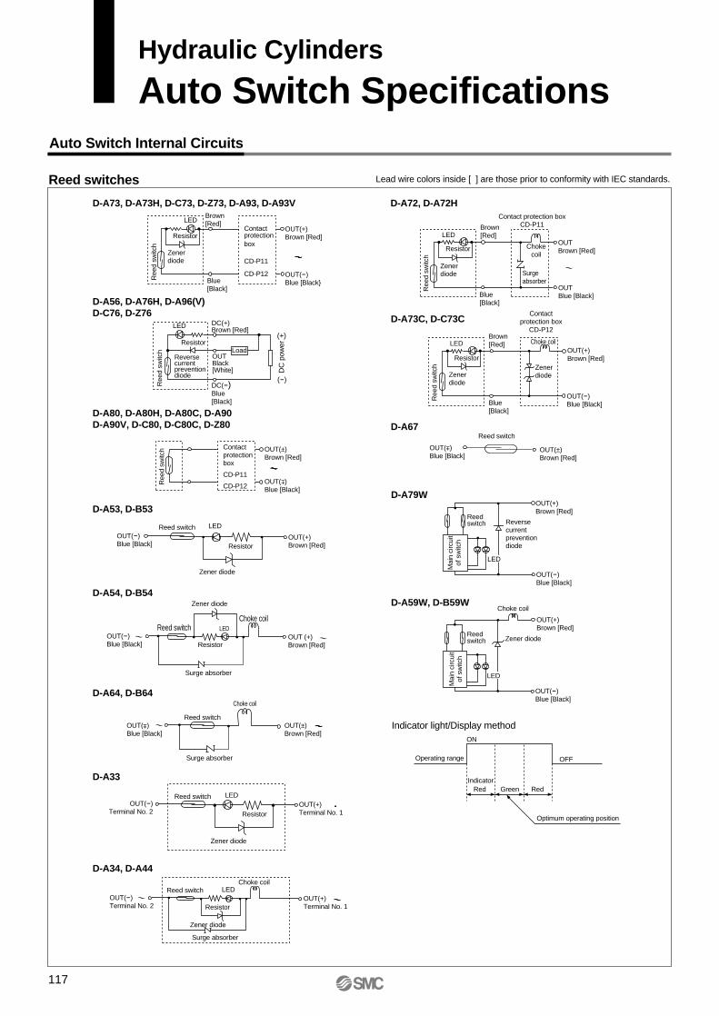
Auto Switch Internal Circuits
Reed switches
D-A72, D-A72H
D-A73C, D-C73C
D-A59W, D-B59W
Indicator light/Display method
D-A79W
D-A67
Blue[Black]
LED
Ree
d sw
itch
Resistor
Zenerdiode
Brown[Red]
OUTBlue [Black]
OUTBrown [Red]
Chokecoil
Contact protection boxCD-P11
Surgeabsorber
Blue[Black]
LED
Ree
d sw
itch
Resistor
Zenerdiode
Brown[Red]
OUT(-) Blue [Black]
OUT(+) Brown [Red]
Choke coil
Contactprotection box
CD-P12
Zener diode
Reed switch
OUT(±) Brown [Red]
OUT( ) Blue [Black]
Reverse current prevention diode
Mai
n ci
rcui
tof
sw
itch
Reedswitch
LED
OUT(+) Brown [Red]
OUT(-) Blue [Black]
Choke coil
Zener diode
Mai
n ci
rcui
tof
sw
itch
Reedswitch
LED
OUT(+) Brown [Red]
OUT(-) Blue [Black]
Optimum operating position
Operating range OFF
ON
RedIndicator
Green Red
Lead wire colors inside [ ] are those prior to conformity with IEC standards.
D-A73, D-A73H, D-C73, D-Z73, D-A93, D-A93V
D-A56, D-A76H, D-A96(V)D-C76, D-Z76
D-A80, D-A80H, D-A80C, D-A90D-A90V, D-C80, D-C80C, D-Z80
D-A53, D-B53
D-A54, D-B54
D-A64, D-B64
D-A33
D-A34, D-A44
LED
Ree
d sw
itch
Resistor
Zenerdiode
Contactprotectionbox
CD-P11
CD-P12
Brown[Red]
Blue[Black]
OUT(+) Brown [Red]
OUT(-) Blue [Black
LED
Ree
d sw
itch
Resistor
Reversecurrent preventiondiode
OUTBlack[White]
DC(+) Brown [Red]
DC(-) Blue[Black]
Load
(+)
(-)
DC
pow
er
Ree
d sw
itch Contact
protection box
CD-P11
CD-P12
OUT(±) Brown [Red]
OUT( ) Blue [Black]
Zener diode
Reed switch LED
Resistor
OUT(-)Blue [Black]
OUT(+)Brown [Red]
Zener diode
Reed switch LED
Resistor
Choke coil
Surge absorber
OUT(-)Blue [Black]
OUT (+) Brown [Red]
Reed switch
Choke coil
Surge absorber
OUT(±) Brown [Red]
OUT( ) Blue [Black]
±
Zener diode
Reed switch LED
Resistor
OUT(-)Terminal No. 2
OUT(+) Terminal No. 1
Zener diode
Reed switch LED
Resistor
Choke coil
Surge absorber
OUT(+) Terminal No. 1
OUT(-) Terminal No. 2
±
±
117
Hydraulic Cylinders
Auto Switch Specifications
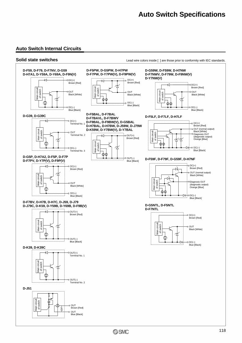
Auto Switch Internal Circuits
Solid state switches
D-F59, D-F79, D-F7NV, D-G59D-H7A1, D-Y59A, D-Y69A, D-F9N(V)
D-G39, D-G39C
D-G5P, D-H7A2, D-F5P, D-F7PD-F7PV, D-Y7P(V), D-F9P(V)
D-F7BV, D-H7B, D-H7C, D-J59, D-J79D-J79C, D-K59, D-Y59B, D-Y69B, D-F9B(V)
D-K39, D-K39C
D-J51
OUTBlack [White]
DC(+)Brown [Red]
DC(–)Blue [Black]
Mai
n ci
rcui
tof
sw
itch
OUTTerminal No. 2
DC(+)Terminal No. 1
DC(–)Terminal No. 3
OUTBrown [Red]
OUTBlue [Black]
D-F5PW, D-G5PW, D-H7PWD-F7PW, D-Y7PW(V), D-F9PW(V)
D-F5BAL, D-F7BALD-F7BAVL, D-F7BWVD-F9BAL, D-F9BW(V), D-G5BALD-H7BAL, D-H7BW, D-J59W, D-J79WD-K59W, D-Y7BW(V), D-Y7BAL
D-G59W, D-F59W, D-H7NWD-F7NWV, D-F79W, D-F9NW(V)D-Y7NW(V)
D-F5LF, D-F7LF, D-H7LF
D-F59F, D-F79F, D-G59F, D-H7NF
D-G5NTL, D-F5NTLD-F7NTL
Diagnosis OUT(diagnostic output)Orange [Blue]
Diagnosis OUT(diagnostic output)Orange [Blue]
Mai
n ci
rcui
tof
sw
itch
Mai
n ci
rcui
tof
sw
itch
Mai
n ci
rcui
tof
sw
itch
Mai
n ci
rcui
tof
sw
itch
Mai
n ci
rcui
tof
sw
itch
Mai
n ci
rcui
tof
sw
itch
Mai
n ci
rcui
tof
sw
itch
Mai
n ci
rcui
tof
sw
itch
Mai
n ci
rcui
tof
sw
itch
OUTBlack [White]
DC(+)Brown [Red]
DC(–)Blue [Black]
OUT(+)Brown [Red]
OUT(–)Blue [Black]
OUT(+)Terminal No. 1
OUT(–)Terminal No. 2
Mai
n ci
rcui
tof
sw
itch
OUTBlack [White]
DC(+)Brown [Red]
DC(–)Blue [Black]
Mai
n ci
rcui
tof
sw
itch
OUT(+)Brown [Red]
OUT(–)Blue [Black]
Lead wire colors inside [ ] are those prior to conformity with IEC standards.
OUTBlack [White]
DC(+)Brown [Red]
DC(–)Blue [Black]
OUT (normal output)Black [White]
DC(+)Brown [Red]
DC(–)Blue [Black]
OUT (normal output)Black [White]
DC(+)Brown [Red]
DC(–)Blue [Black]
OUTBlack [White]
DC(+)Brown [Red]
DC(–)Blue [Black]
Auto Switch Specifications
118

Basic Wiring
Solid state 3-wire, NPN
Sink input specifications
2-wire<Solid state>
Source input specifications
2-wire with 2-switch AND connection
2-wire with 2-switch OR connection
2-wire 2-wire
Solid state 3-wire, PNP
Example: Power supply is 24VDC. Voltage decline in switch is 4V.
Example: Load impedance is 3kΩ.Leakage current from switch is 1mA.
(Power supplies for switch and load are separate.)
Connection Examples for AND (Series) and OR (Parallel)
Examples of Connection to PLC
The connection method will vary depending on the PLC input specifi-cations. Connect accordingly.
When two switches are connected in series, a load may malfunction because the load voltage will decline when in the ON state.The indicator lights will light up if both of the switches are in the ON state.
<Solid state>When two switches are connected in parallel, malfunction may occur because the load voltage will increase when in the OFF state.
Blue[Black]
Load
Brown [Red]
Black[White]
Maincircuit
of switch
Brown[Red]
Load
Blue[Black]
Black[White]
Maincircuit
of switch
LoadBlue[Black]
Brown[Red]
Maincircuit
of switch
Load
Blue[Black]
Brown[Red]
Maincircuit
of switch
Load
Brown[Red]
Blue[Black]
Black[White]
PLC internal circuitCOM
Switch
InputBlack[White]
Brown[Red]
Blue[Black]
PLC internal circuitCOM
Switch
InputBrown[Red]
Blue[Black] PLC internal circuit
Switch
Input
COM
Blue[Black]
Brown[Red]
PLC internal circuitCOM
Switch
InputBlack[White]
Brown[Red]
Blue[Black]
Switch 1
Switch 2
Load
Blue[Black]
Brown[Red]
Blue[Black]
Brown[Red]
Switch 1
Switch 2
Load
Brown[Red]
Blue[Black]
Brown[Red]
Blue[Black]
3-wireAND connection for NPN output(using relays)
OR connection for NPN output
Switch 1
Switch 2
LoadSwitch 1
Brown[Red]
Switch 2
Black[White]
Blue[Black]
Relay
RelayBlack[White]
Load
Relaycontact
Switch 1
Brown[Red]
Switch 2
Load
Brown[Red]
AND connection for NPN output(performed with switches only)
The indicator lights will light up when both switches are turned ON.
<Reed switch>
2-wire<Reed switch>
Indicatorlight,
protectioncircuit,
etc.
Brown[Red]
Blue[Black]
Load
Brown[Red]
Blue[Black]
Load
3-wire, NPN 3-wire, PNP
Brown [Red]
Blue[Black]
Blue[Black]
Black[White]
Black[White]
Blue[Black]
Brown[Red]
Blue[Black]
Black[White]
Blue[Black]
Black[White]
Brown[Red]
Because there is no current leakage, the load voltage will not increase when turned OFF. However, depending on the number of switches in the ON state, the indicator lights may sometimes grow dim or not light up because of the dispersion and reduction of the current flowing to the switches.
Indicatorlight,
protectioncircuit,
etc.
Load voltage at ON = – x 2 pcs.
= 24V – 4V x 2 pcs. = 16V
Power supply voltage
Residual voltage
Leakagecurrent
LoadimpedanceLoad voltage at OFF = x 2 pcs. x
= 1mA x 2 pcs. x 3kΩ= 6V
Hydraulic CylindersAuto Switch Connections and Examples
119
Maincircuit
of switch
–
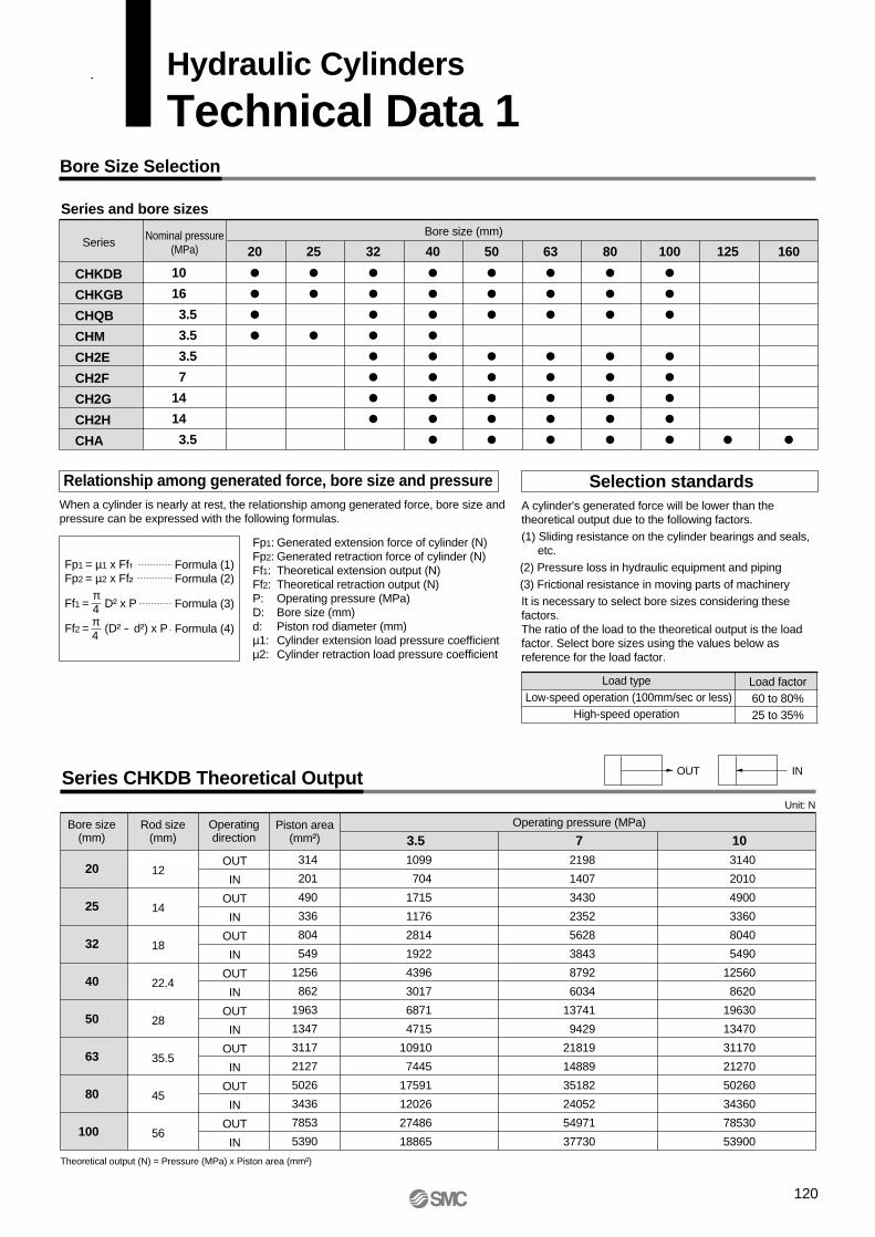
Bore Size Selection
Series and bore sizes
Relationship among generated force, bore size and pressureWhen a cylinder is nearly at rest, the relationship among generated force, bore size and pressure can be expressed with the following formulas.
Fp1: Generated extension force of cylinder (N) Fp2: Generated retraction force of cylinder (N) Ff1: Theoretical extension output (N)Ff2: Theoretical retraction output (N)P: Operating pressure (MPa)D: Bore size (mm)d: Piston rod diameter (mm)µ1: Cylinder extension load pressure coefficientµ2: Cylinder retraction load pressure coefficient
Fp1 = µ1 x Ff₁Fp2 = µ2 x Ff₂
Ff1 = D² x P
Ff2 = (D² - d²) x P
Formula (1)Formula (2)
Formula (3)
Formula (4)
π4π4
Selection standards
Load typeLow-speed operation (100mm/sec or less)
High-speed operation
Load factor60 to 80%25 to 35%
SeriesBore size (mm)Nominal pressure
(MPa)
10
16
3.5
3.5
3.5
7
14
14
3.5
20
32
40
50
63
80
100
125
160
25
CHKDB
CHKGB
CHQB
CHM
CH2E
CH2F
CH2G
CH2H
CHA
Series CHKDB Theoretical Output
Bore size(mm)
Rod size(mm)
Piston area(mm²)
OUT
IN
OUT
IN
OUT
IN
OUT
IN
OUT
IN
OUT
IN
OUT
IN
OUT
IN
20
25
32
40
50
63
80
100
12
14
18
22.4
28
35.5
45
56
314
201
490
336
804
549
1256
862
1963
1347
3117
2127
5026
3436
7853
5390
3.5 1099
704
1715
1176
2814
1922
4396
3017
6871
4715
10910
7445
17591
12026
27486
18865
10 3140
2010
4900
3360
8040
5490
12560
8620
19630
13470
31170
21270
50260
34360
78530
53900
Operating pressure (MPa)
7 2198
1407
3430
2352
5628
3843
8792
6034
13741
9429
21819
14889
35182
24052
54971
37730
Unit: N
Theoretical output (N) = Pressure (MPa) x Piston area (mm²)
OUT IN
A cylinder's generated force will be lower than the theoretical output due to the following factors.(1) Sliding resistance on the cylinder bearings and seals,
etc.(2) Pressure loss in hydraulic equipment and piping(3) Frictional resistance in moving parts of machineryIt is necessary to select bore sizes considering these factors.The ratio of the load to the theoretical output is the load factor. Select bore sizes using the values below as reference for the load factor.
Operatingdirection
Hydraulic Cylinders
Technical Data 1
120

Series CHKGB Theoretical Output
Series CHQB Theoretical Output
Bore size(mm)
Rod size(mm)
Piston area(mm²)
OUT
IN
OUT
IN
OUT
IN
OUT
IN
OUT
IN
OUT
IN
OUT
IN
OUT
IN
20
25
32
40
50
63
80
100
12
14
18
22.4
28
35.5
45
56
314
201
490
336
804
549
1256
862
1963
1347
3117
2127
5026
3436
7853
5390
3.51099
704
1715
1176
2814
1922
4396
3017
6871
4715
10910
7445
17591
12026
27486
18865
103140
2010
4900
3360
8040
5490
12560
8620
19630
13470
31170
21270
50260
34360
78530
53900
165024
3216
7840
5376
12864
8784
20096
13792
31408
21552
49872
34032
80416
54976
125648
86240
7 2198
1407
3430
2352
5628
3843
8792
6034
13741
9429
21819
14889
35182
24052
54971
37730
Unit: N
Operating pressure (MPa)
Series CHM Theoretical Output
Bore size(mm)
Piston area(mm²)
Rod size(mm)
20
32
40
50
63
80
100
10
16
16
20
20
25
30
OUT
IN
OUT
IN
OUT
IN
OUT
IN
OUT
IN
OUT
IN
OUT
IN
314
235
804
603
1256
1055
1963
1649
3117
2803
5026
4535
7853
7147
1314
235
804
603
1256
1055
1963
1649
3117
2803
5026
4535
7853
7147
471
352
1206
904
1884
1582
2944
2473
4675
4204
7539
6802
11779
10720
628
470
1608
1206
2512
2110
3926
3298
6234
5606
10052
9070
15706
14294
785
587
2010
1507
3140
2637
4907
4122
7792
7007
12565
11337
19632
17867
942
705
2412
1809
3768
3165
5889
4947
9351
8409
15078
13605
23559
21441
1099
822
2814
2110
4396
3692
6870
5771
10909
9810
17591
15872
27485
25014
1.5 2 2.5 3 3.5Operatingdirection
Operating pressure (MPa)
Unit: N
Bore size(mm)
Piston area(mm²)
Rod size(mm)
20
25
32
40
10
12
16
18
OUT
IN
OUT
IN
OUT
IN
OUT
IN
314
235
490
377
804
603
1256
1002
1 1.5 2 2.5 3 3.5Operatingdirection
Operating pressure (MPa)
Unit: N
314
235
490
377
804
603
1256
1002
471
352
735
565
1206
904
1884
1503
628
470
980
754
1608
1206
2512
2004
785
587
1225
942
2010
1507
3140
2505
942
705
1470
1131
2412
1809
3768
3006
1099
822
1715
1319
2814
2110
4396
3507
Operatingdirection
Technical Data 1
121

Series CH2E/CH2F/CH2G/CH2H Theoretical Output
Series CHA Theoretical Output
Bore size(mm)
Piston area(mm²)
Rod size(mm)
40
50
63
80
100
125
160
18
20
22.4
28
35.5
35.5
45
OUT
IN
OUT
IN
OUT
IN
OUT
IN
OUT
IN
OUT
IN
OUT
IN
1257
1002
1963
1649
3117
2723
5027
4411
7854
6864
12272
11282
20106
18516
1 1.5 2 2.5 3 3.5Operatingdirection
Operating pressure (MPa)
Unit: N
1257
1002
1963
1649
3117
2723
5027
4411
7854
6864
12272
11282
20106
18516
1886
1503
2945
2474
4676
4085
7541
6617
11781
10296
18408
16923
30159
27774
2514
2004
3926
3298
6234
5446
10054
8822
15708
13728
24544
22564
40212
37032
3143
2505
4908
4123
7793
6808
12568
11028
19635
17160
30680
28205
50265
46290
3771
3006
5889
4947
9351
8169
15081
13233
23562
20592
36816
33846
60318
55548
4400
3507
6871
5772
10910
9531
17595
15439
27489
24024
42952
39487
70371
64806
122
Hydraulic Cylinders: Technical Data 1
Bore size(mm)
Rod size(mm)
Piston area(mm²)
OUT
IN
OUT
IN
OUT
IN
OUT
IN
OUT
IN
OUT
IN
OUT
IN
OUT
IN
OUT
IN
OUT
IN
OUT
IN
32
40
50
63
80
100
40
50
63
80
100
18
22.4
28
35.5
45
56
18
22.4
28
35.5
45
B-s
erie
s ro
dC
-ser
ies
rod
804
550
1256
862
1963
1347
3116
2126
5024
3434
7850
5388
1256
1002
1963
1569
3116
2500
5024
4035
7850
6260
1804
550
1256
862
1963
1347
3116
2126
5024
3434
7850
5388
1256
1002
1963
1569
3116
2500
5024
4035
7850
6260
3.52813
1923
4396
3017
6869
4715
10905
7442
17584
12020
27475
18859
4396
3506
6869
5490
10905
8751
17584
14121
27475
21911
54019
2748
6280
4311
9813
6735
15578
10632
25120
17172
39250
26941
6280
5008
9813
7843
15578
12501
25120
20174
39250
31302
75627
3847
8792
6035
13738
9429
21810
14885
35168
24041
54950
37718
8792
7012
13738
10980
21810
17502
35168
28243
54950
43823
108038
5495
12560
8621
19625
13471
31157
21264
50240
34344
78500
53882
12560
10017
19625
15686
31157
25002
50240
40347
78500
62604
1411254
7693
17584
12070
27475
18859
43619
29769
70336
48081
109900
75435
17584
14023
27475
21961
43619
35003
70336
56486
109900
87645
Operating pressure (MPa) Unit: N
Operatingdirection

Stroke Selection (maximum stroke based on buckling strength)
Refer to the stroke range limit charts regarding rod buckling due to load weight.The values in these tables indicate the maximum stroke that can be used in a situation when air is being supplied while the cylinder is stop-ped in an intermediate position by a) an external force acting on the pis-
ton rod and/or by b) an external stopper. Since the maximum usable stroke varies depending on the diameter of the piston rod and operating conditions, verify the applicability using the stroke range limit charts.
Series CHM Stroke range limit charts: Bore sizes ø20, ø25, ø32, ø40
Symbol Mounting orientation Mounting orientation Mounting orientation Mounting orientation
Bore size ø20 Bore size ø25
Load (kN) Load (kN)
Str
oke
(m
m)
1000
500
100
500.05 0.1 0.5 1 2 0.05 0.1 0.5 1 2
F
F
F
F F
F F
F
F
F
64
1 5
8 3 7 6 5 4 8 3 71
Load (kN) Load (kN)
Bore size ø32 Bore size ø40
Str
oke
(m
m)
1000
500
100
500.05 0.1 0.5 1 2 3 0.1 0.05 0.5 1 2 5
6 8 6 4 8 3 75
1
3 74
5
1
Symbol Symbol Symbol
Hydraulic Cylinders
Technical Data 2
123

Series CHA Stroke range limit charts: Bore sizes ø40, ø50, ø63, ø80
Symbol Mounting orientation Mounting orientation Mounting orientation Mounting orientation
F F
F
F
F F
F F
F F
F
F
6
6
1
1 5
24 8 9 3 7
6
1
Load (kN) Load (kN)
Bore size ø40 Bore size ø50
Str
oke
(mm
)
3000
2000
1000
500
100
500.1 0.5 1 5 10 0.5 1 5 10
Load (kN) Load (kN)
Bore size ø63 Bore size ø80
Str
oke
(mm
)
3000
2000
1000
500
100
500.5 1 5 10 20 30 0.5 1 5 10 20 30
5
2 4
8
3 7
9
52 4 8
93 7
6
5
1 24 8
93 7
Symbol Symbol Symbol
124
Hydraulic Cylinders: Technical Data 2

Series CHA Stroke range limit charts: Bore sizes ø100, ø125, ø160
Symbol Mounting orientation Symbol Mounting orientation Symbol Mounting orientation Symbol Mounting orientation
F F
F
F
F F
F F
F F
F
F
Load (kN) Load (kN)
Bore size ø100 Bore size ø125
Str
oke
(mm
)
3000
2000
1000
500
100
50 0.5 1 5 10 20 50 1 5 10 20 30 50
Load (kN)
Bore size ø160
Str
oke
(mm
)
3000
2000
1000
500
100
505 10 20 50 100 200
6 1 5 2 4 3 7 1 5 2 4 3
69
7
68
9
61
52 4
8 3 79
Technical Data 2
125

Series CH2E, CH2F, CH2G, CH2H Stroke range limit chart: Bore sizes ø32 & ø40
B-rod
Load (kN)
Str
oke
(mm
)
2000
1000
500
100
50
100.1 0.5 1 5 10 20
Bore size ø32
6
15 2 4 8 3 7
Load (kN) Load (kN)
B-rod Bore size ø40
C-rod
Str
oke
(mm
)
2000
1000
500
100
500.5 1 5 10 20 0.5 1 5 10 20
6
1
2
4 83 7
6
1
52 4
8
3 75
Symbol Mounting orientation Symbol Mounting orientation Symbol Mounting orientation Symbol Mounting orientation
F F
F
F
F F
F F
F
F
F
126
Hydraulic Cylinders: Technical Data 2

Technical Data 2
Series CH2E, CH2F, CH2G, CH2H Stroke range limit charts: Bore sizes ø50, ø63, ø80, ø100
Bore size ø50
Load (kN) Load (kN)
B-rod C-rod
Str
oke
(mm
)
2000
1000
500
100
500.5 1 5 10 20 30 0.5 1 5 10 20 30
615 2 4 8 3 7
61
24 8 3 75
6
Load (kN) Load (kN)
B-rod C-rod
Str
oke
(mm
)
2000
1000
500
100
500.5 1 5 10 20 50 0.5 1 5 10 20 50
Load (kN) Load (kN)
B-rod C-rod
Str
oke
(mm
)
2000
1000
500
100
501 5 10 20 50 1 5 10 20 50
1 2 85 4 3 7 6
1 2 35 4 8 7
6
1 2
4 8 3 7
61 5
24 8 3 7
5
Bore size ø63
Bore size ø80
Load (kN) Load (kN)
B-rod C-rod
Str
oke
(mm
)
2000
1000
500
100
501 5 10 20 50 100 1 5 10 20 50 100
6 61 24 8 83 37 75
12
45
Bore size ø100
127

Hydraulic Cylinders
Technical Data 3
Speed (mm/s)
Load
wei
ght (
kg)
Speed (mm/s)
ø160
ø125
ø100ø80
ø63
ø50
ø40
Load
wei
ght (
kg)
Relationship Between Load Weight and Speed
Load weight in light of cushion performance characteristics –– Speed charts
Series CHA (aluminum tube): Load weight for horizontal motion — Speed chart (retraction, pressure 3.5MPa)
Series CHA (aluminum tube): Load weight for horizontal motion — Speed chart (extension, pressure 3.5MPa)
m
m
10100
1000
10000
100000
100 1000
ø160
ø125
ø100ø80
ø63
ø50
ø40
10100
1000
10000
100000
100 1000
Set up the inertial force that can be absorbed by the cylinder cushion within the values shown in the graphs.∗ In case of vertical motion, since surge pressure is generated by the gravitational force, adjust the load weight and speed below the maximum
allowable pressure.
128

Speed (mm/s)
Load
wei
ght (
kg)
Speed (mm/s)
ø160
ø125
ø100ø80
ø63
ø50
ø40
Load
wei
ght (
kg)
Series CHA (steel tube): Load weight for horizontal motion — Speed chart (retraction, pressure 5MPa)
Series CHA (steel tube): Load weight for horizontal motion — Speed chart (extension, pressure 5MPa)
m
m
10100
1000
10000
100000
100 1000
ø160
ø125
ø100ø80
ø63
ø50
ø40
10100
1000
10000
100000
100 1000
Technical Data 3
129

Series CH2E: Load weight for horizontal motion — Speed chart (B-rod retraction, pressure 3.5MPa)
m
m
m
Series CH2E: Load weight for horizontal motion — Speed chart (C-rod retraction, pressure 3.5MPa)
Series CH2E: Load weight for horizontal motion — Speed chart (extension, pressure 3.5MPa)
Speed (mm/s)
Load
wei
ght (
kg)
10100
1000
10000
100 1000
Speed (mm/s)
Load
wei
ght (
kg)
10100
1000
10000
100 1000
Speed (mm/s)
Load
wei
ght (
kg)
10100
1000
10000
100 1000
ø100
ø80
ø63ø50
ø40ø32
ø100
ø80
ø63ø50
ø40
ø100
ø80
ø63ø50
ø40ø32
130
Hydraulic Cylinders: Technical Data 3

Series CH2F: Load weight for horizontal motion — Speed chart (B-rod retraction, pressure 7MPa)
m
m
m
Technical Data 3
Series CH2F: Load weight for horizontal motion — Speed chart (C-rod retraction, pressure 7MPa)
Series CH2F: Load weight for horizontal motion — Speed chart (extension, pressure 7MPa)
Speed (mm/s)
ø100
ø80
ø63
ø50
ø40
ø32
ø100
ø80
ø63
ø50
ø40
ø100
ø80
ø63
ø50
ø40
ø32
Load
wei
ght (
kg)
10100
1000
10000
100 1000
Speed (mm/s)
Load
wei
ght (
kg)
10100
1000
10000
100 1000
Speed (mm/s)
Load
wei
ght (
kg)
10100
1000
10000
100 1000
131

Series CH2G, CH2H: Load weight for horizontal motion — Speed chart (B-rod retraction, pressure 14MPa)
m
m
m
Series CH2G, CH2H: Load weight for horizontal motion — Speed chart (C-rod retraction, pressure 14MPa)
Series CH2G, CH2H: Load weight for horizontal motion — Speed chart (extension, pressure 14MPa)
Speed (mm/s)
ø100
ø80
ø63ø50
ø40
ø32
ø100
ø80
ø63
ø50
ø40
ø100
ø80
ø63
ø50
ø40ø32
Load
wei
ght (
kg)
10100
1000
10000
100000
100 1000
Speed (mm/s)
Load
wei
ght (
kg)
10100
1000
10000
100000
100 1000
Speed (mm/s)
Load
wei
ght (
kg)
10100
1000
10000
100000
100 1000
132
Hydraulic Cylinders: Technical Data 3

Piston Speed, Required Fluid Volume and Piping Size Selection
Relationship between piston speed and fluid volume
Effective inside diameter of piping
Q₁ = D²⋅ υ⋅π__4
6_____1000
Q₂ = (D² - d²) ⋅ υ⋅π__4
6_____1000
…………… Formula (1)
..… Formula (2)
……… Formula (3)din² x 10-₃π__
4V = ⋅Q 1___
60
Q₁: Required fluid volume for extension (l/min)Q₂: Required fluid volume for retraction (l/min)D: Bore size (cm)d: Piston rod diameter (cm)υ: Piston speed (mm/s)
V: Fluid flow velocity (m/s)Q: Fluid volume (l/min)din: Effective inside diameter of piping (mm)
It is generally necessary to select a piping diameter that will not allow the fluid flow velocity to exceed the values shown in the chart below.If the fluid flow velocity exceeds this value, turbulent flow and overheating may occur in conjunction with pressure loss.
Rubber hose
Steel piping
5m/s
4.5m/s
Fluid flow velocity
How to read the chart: Example) The required flow rate necessary to operate a ø50 cylinder at a speed of 100mm/s is 12l/min.When the 3/8" (ø9.5) rubber hose is used for piping, the flow velocity in the piping will be about 2.8m/s.
Flow velocity inside pipe (m/s) Piston speed (mm/s)
600
500
400
300
200
100
80
60
50
40
30
20
12
10987
6
5
4
3
2
Flo
w r
ate
(l/m
in)
General range of rubber hose (max. 5m/s)
General range of steel pipe (max. 4.5m/s)
1" (ø25.4)
ø25ø21
ø9
ø8
ø7
7 6 5 4 3 2 20 30 40 50 60 80 100 200 300 400 5002.8
Hydraulic Cylinders
Technical Data 4
133
This information is intended to help you find the required fluid volume and piping size to operate a cylinder at a specified speed.
1 1/2"(ø38.1) rubber hose
1 1/4"(ø31.8) rubber hoseø26
rubber hose
ø23
3/4"(ø19) rubber hose
ø17
ø15
5/8"(ø15.3) rubber hose
ø13
1/2" (ø12.7)
rubber hose
ø12
ø10
3/8"(ø9.5)
rubber hose
1/4"(ø6.3) rubber hose
ø6ø5
ø4 (steel pipe I.D.)
Cylind
er bo
re si
ze ø
160
Cylind
er bo
re si
ze ø
125
Cylind
er bo
re si
ze ø
100
Cylind
er bo
re si
ze ø
80
Cylind
er bo
re si
ze ø
63
Cylind
er bo
re si
ze ø
50
Cylind
er bo
re si
ze ø
40
Cylind
er bo
re si
ze ø
32
Cylind
er bo
re si
ze ø
25
Cylind
er bo
re si
ze ø
20

134

Hydraulic Cylinders
Safety Instructions
Note 1) ISO 4413: Hydraulic fluid power — General rules for the application of equipment to transmission and control systems
Note 2) JIS B 8361: General Rules for Hydraulic Equipment
Warning
Caution : Operator error could result in injury or equipment damage.
Warning : Operator error could result in serious injury or loss of life.
Danger : In extreme conditions, there is a possible result of serious injury or loss of life.
These safety instructions are intended to prevent a hazardous situation and/or equipment damage. These instructions indicate the level of potential hazard by a label of "Caution", "Warning", or "Danger". To ensure safety, be sure to observe ISO 4413 Note 1), JIS B 8361 Note 2) and other safety practices.
1. The compatibility of hydraulic cylinders is the responsibility of the person who designs the hydraulic system or decides its specifications.Since the products specified here are used in various operating conditions, their compatibility with the specific hydraulic system must be based on specifications or after analysis and/or tests to meet your specific requirements.
2. Only trained personnel should operate hydraulic machinery and equipment.Oil hydraulics can be dangerous if an operator is unfamiliar with it. Assembly, handling, or repair of hydraulic systems should be performed by trained and experienced operators.
3. Do not service machinery/equipment or attempt to remove components until safety is confirmed.1. Inspection and maintenance of machinery/equipment should only be performed after confirmation of
safe locked-out control positions.
2. When equipment is to be removed, confirm the safety process as mentioned above. Cut the oil supply pressure and electric power for this equipment and confirm that there is no pressure in the system.
3. Before machinery/equipment is restarted, take measures to prevent shooting-out of cylinder piston rod, etc., and proceed with caution.
4. Contact SMC if the product is to be used in any of the following conditions:1. Conditions and environments beyond the given specifications, or if product is used outdoors.
2. Installation on equipment in conjunction with atomic energy, railway, air navigation, vehicles, medical equipment, food and beverages, recreation equipment, emergency stop circuits, press applications, or safety equipment.
3. An application that has the possibility of having negative effects on people, property, or animals, and therefore requires special safety analysis.
135
Hydraulic Cylinder Precautions 1Be sure to read before handling.
1. There is a danger of sudden or erratic action by cylinders if sliding parts of machinery are twisted, causing changes in forces to occur. In such cases, human injury may occur, e.g., by catching hands or feet in the machinery, or damage to the machinery itself may occur. Therefore, the machinery should be adjusted to operate smoothly and designed to prevent such dangers.
2. A protective cover is recommended to minimize the risk of personal injury.If driven objects and moving parts of a cylinder pose a serious danger of human injury, design the structure to avoid direct contact with the human body.
3. Securely tighten all stationary parts and connected parts so that they will not become loose.Especially when a cylinder operates with high frequency or is installed where there is a lot of vibration, ensure that all parts remain secure.
4. A deceleration circuit or shock absorber may be required.When a driven object is operated at high speed or the load is heavy, a cylinder’s cushion will not be sufficient to absorb the impact. Install a deceleration circuit to reduce the speed before cushioning, or install an external shock absorber to relieve the impact. In this case, the rigidity of the machinery should also be examined.
5. Take into account a possible drop in operat-ing pressure due to a power outage.When a cylinder is used as a clamping mechanism, there is a danger of a work piece dropping if there is a decrease in clamping force due to a drop in circuit pressure caused by a power outage. Therefore, safety equipment should be installed to prevent damage to machinery and human injury. Suspension mechanisms and lifting devices also be considered as drop prevention equipment.
6. Take into account a possible loss of power source.Measures should be taken to protect against human injury and equipment damage in the event that there is a loss of power to equipment controlled by air pressure, electricity, or hydraulics.
7. Design circuitry to prevent sudden lurching of driven objects.When hydraulic pressure in a cylinder is zero, the driven object will lurch at high speed if pressure is applied to one side of the piston. Therefore, equipment should be selected and circuits designed to prevent sudden lurching because there is a danger of human injury and/or damage to equipment when this occurs.
8. Take into account emergency stops.Design the system so that human injury and/or damage to machinery and equipment will not occur when machinery is stopped by a manual emergency stop or a safety device triggered by abnormal conditions such as a power outage.
1. Confirm the specifications.The products featured in this catalog are designed for use in industrial hydraulic system applications only. If the products are used in conditions where pressure and/or temperature are out of specification, damage and/or malfunction may occur. Do not use in these conditions. (Refer to specifications.)Consult with SMC if a fluid other than hydraulic fluid is to be used.
2. Intermediate stopsSince hydraulic cylinders are not guaranteed for zero fluid leakage, it may not be possible to hold a stopped position for an extended period of time.
3. Consider surge pressure.Use cylinders that can withstand the surge pressures (maximum allowable pressure) generated in hydraulic systems. (Refer to specifications.)Inside cylinders, pressure that is higher than the set pressure for the relief valve may be generated, e.g., internal pressure due to load inertia or surge pressure when switching valves.Consider these factors and determine the operating pressure so that the pressure generated inside cylinders will be within the maximum allowable pressure.Pressure terminology used in this catalog is defined as follows:Nominal pressure: Pressure assigned to a cylinder for convenient identification. It is not necessarily the same as the operating pressure which guarantees performance under specified conditions.Maximum allowable pressure: The maximum allowable value for the pressure that is generated inside cylinders (such as surge pressure).Proof pressure: Test pressure that the cylinder must be able to withstand without lowering system performance when returning to the nominal pressure.
Minimum operating pressure: Minimum pressure at which a horizontally installed cylinder operates with no-load.
4. Take into account compatibility with hydraulic fluids.
Selection
Design
Warning
Warning
Hydraulic fluid Compatibility
Compatible
Compatible
Compatible
∗Not compatible
Consult with SMC regarding fluids marked "∗ ".
Standard mineral hydraulic fluid
W/O hydraulic fluid
O/W hydraulic fluid
Water/Glycol hydraulic fluid
Phosphate hydraulic fluid
136
Design
Warning9. Consider the action of the system when
operation is restarted after an emergency stop or abnormal stop.Design machinery so that human injury or equipment damage will not occur upon restart of operation. When the cylinder has to be reset at the starting position, install safe manual control equipment.

1. Operate within the limits of the maximum stroke.The piston rod will be damaged if operated beyond the maximum stroke. Refer to the hydraulic cylinder stroke selection procedures (pages 123 to 127) for maximum strokes.
2. Operate the piston within a range that will prevent impact damage from occurring at the stroke end.Ensure a safety margin so that damage will not occur when the piston, having inertial force, stops by striking the cover at the stroke end.
1. Take load factors and piston speed on page 120 into consideration and determine the operability by referring to "Relationship between load weight speed" charts on pages 128 through 132.
2. When using cylinders without a cushion, either slow the speed down so that it is 50mm/s or less (i.e., a speed where no metal sounds are heard) when the piston hits the cover, or install a stopper on the outside of the cylinder.
3. Use a flow control valve to adjust the hydraulic cylinder drive speed, gradually increasing from a low speed to the desired speed setting.
4. Provide intermediate supports for long stroke cylinders.Provide intermediate supports for cylinders with long strokes to prevent piston rod damage due to sagging of the piston rod, deflection of the tube, vibration and external loads.
Caution
Selection
Hydraulic Cylinder Precautions 2Be sure to read before handling.
Mounting
Caution1. Be certain to align the axis center of the
piston with the load and direction of movement when connecting.When not properly aligned, twisting of the piston rod and tubing may occur, and damage may be caused due to wear on areas such as the inner tube surface, bushings, piston rod surface and seals.
2. When an external guide is used, connect the piston rod end and the load in such a way that there is no interference at any point within the stroke.
3. Do not scratch or gouge the sliding parts of the cylinder tube by striking or grasping it with other objects.Cylinder bores are manufactured to precise tolerances, so that even a slight deformation may cause faulty operation.
4. Do not use until you can verify that equip-ment can operate properly.Verify correct mounting by performing suitable function and leakage inspections after piping and power is connected, following mounting, repairs, or conversions.
Mounting
Caution5. Instruction manual
The product should be mounted and operated after thoroughly reading the manual and understanding its contents.Keep the instruction manual where it can be referred to easily.
1. Preparation before pipingBefore piping is connected, it should be thoroughly flushed out with air or water to remove chips, cutting oil and other debris.
2. Wrapping of sealant tapeWhen screwing together pipes and fittings, be certain that chips from the pipe threads and sealing material do not get inside the piping.Also, when sealant tape is used, leave 1.5 to 2 thread ridges exposed at the end of the threads.
Piping
Caution
3. Set up so that air cannot accumulate inside piping.
Wrapping direction
Sealant tape
Expose approx. 2 threads
137
1. Readjust using the cushion needle.Cushions are adjusted at the time of shipment. However, the cushion needle on the cover should be readjusted when the product is put into service, based on factors such as the size of the load and the operating speed. When the cushion needle is turned clockwise, the restriction becomes smaller and the cushion's effectiveness is increased.
2. Do not operate with the cushion needle fully closed.This will contribute to the generation of surge pressure, and the cylinder or equipment can be damaged.
3. Do not loosen the cushion needle too much.This can cause fluid to be blown out.
Cushion
Caution

1. Operate after opening the air release valve and completely releasing any internal air.Residual air can cause a malfunction.
2. When adjusting the air release, do not loosen the plug too much.Use caution, since loosening the plug too much may cause it to fly out or fluid to blow out, posing a danger of human injury.
Air Release
Caution
1. Install hydraulic fluid filters.Provide your hydraulic system with hydraulic fluid filters with a filtration degree of 10mm or finer.Refer to SMC's hydraulic filter specifications.
2. Use the product within the specified range of fluid and ambient temperature.Take measures to prevent freezing, since moisture in hydraulic fluid will freeze at 0°C or below and this may cause damage to seals and lead to a malfunction.
3. Use hydraulic fluid with a viscosity grade equivalent to ISO VG32 or VG46.
Caution
1. Use clean fluid.Do not use deteriorated fluid or fluid containing foreign matter, moisture or corrosive additives, as this can cause the malfunction and damage or corrosion of parts.
Hydraulic Fluid
Warning
Hydraulic Cylinder Precautions 3Be sure to read before handling.
Operating Environment
Warning1. Do not use in environments where there is a
danger of corrosion.Refer to the construction drawings for cylinder materials.
2. In dusty locations, or where there is exposure to chips and spatter, install a protective cover.When there is splashing or spraying of water or coolant, use water resistant hydraulic cylinders.
1. Perform maintenance inspection and services according to the procedures indicated in the instruction manual.Improper handling and maintenance services may cause malfunctioning and damage of machinery or equipment to occur.
2. Removal of equipmentWhen machinery is removed, first ensure that the appropriate measures are in place to prevent the fall or sudden erratic movement of driven objects and equipments. Then cut off the electric power and reduce the pressure in the system to zero.When machinery is restarted, proceed with caution after confirming measures to prevent cylinder lurching.
Maintenance
Warning
1. Perform periodic maintenance procedures on filters installed in a hydraulic system in order to keep the fluid clean.If the fluid used in hydraulic cylinders contains foreign matter, parts such as the piston seals and rod seals will be damaged.
Caution
138

Auto Switch Precautions 1Be sure to read before handling.
1. Confirm the specifications.Read the specifications carefully and use the product appropriately. The product may be damaged or malfunction if it is used outside the range of specifications for load current, voltage, temperature or impact.
2. Take precautions when multiple cylinders are used close together.When two or more auto switch cylinders are lined up in close proximity to each other, magnetic field interference may cause the switches to malfunction. Maintain a minimum cylinder separation of 40mm. (When the allowable interval is specified for each cylinder series, use the indicated value.)
3. Monitor the length of time that a switch is ON at an intermediate stroke position.When an auto switch is placed at an intermediate position of the stroke and a load is driven at the time the piston passes, the auto switch will operate, but if the speed is too great the operating time will be shortened and the load may not operate properly. The maximum detectable piston speed is:
In case of a high piston speed, it is possible to extend the operating time of the load by using an auto switch (D-F5NT, D-F7NT, and D-G5NT) with a built-in off delay timer (approx. 200ms).
4. Keep wiring as short as possible.<Reed switches>As the length of the wiring to a load gets longer, the rush current at switching ON becomes greater, and this may shorten the product’s life. (The switch will stay ON all the time.)1) For an auto switch without a contact protection circuit, use a
contact protection box when the wire length is 5m or longer.2) Even when an auto switch has a built-in contact protection
circuit, if the lead wire length is 30m or more, the rush current cannot be adequately absorbed and the life of the switch may be shortened. Contact SMC, as it may be necessary in this case to connect a contact protection box to extend the switch life.
<Solid state switches>3) Although wire length should not affect switch function, use a
wire 100m or shorter.
5. Monitor the internal voltage drop of the switch.<Reed switches>1) Switches with an indicator light (except D-A56, D-A76H, D-
A96, D-A96V, D-C76, D-Z76)• If auto switches are connected in series as shown below,
take note that there will be a large voltage drop because of internal resistance in the light emitting diodes. (Refer to internal voltage drop in the auto switch specifications.)[The voltage drop will be “n” times larger when “n” auto switches are connected.]Even though an auto switch operates normally, the load may not operate.
Design and Selection
Auto switch operating range (mm)
Load operating time (ms) x 1000V (mm/s) =
• Similarly, when operating below a specified voltage, it is possible that the load may be inoperable even though the auto switch function is normal. Therefore, the formula below should be satisfied after confirming the minimum operating voltage of the load.
2) If the internal resistance of a light emitting diode causes a problem, select a switch without an indicator light (D-A6, D-A80, D-A80H, D-A90, D-A90V, D-B64, D-C80, or D-Z80).
<Solid state switches>3) Generally, the internal voltage drop will be greater with a 2-
wire solid state auto switch than with a reed switch. Take the same precautions as in 1).Also, note that a 12VDC relay is not applicable.
6. Be careful of leakage current.<Solid state switches>With a 2-wire solid state auto switch, current (leakage current) flows to the load to operate the internal circuit even when in the OFF state.
If the condition given in the above formula is not met, it will not reset correctly (stays ON). Use a 3-wire switch if this specification cannot be satisfied.Moreover, leakage current flow to the load will be “n” times larger when “n” auto switches are connected in parallel.
7. Do not use a load that generates surge voltage.<Reed switches>If driving a load such as a relay that generates surge voltage, use a switch with a built-in contact protection circuit or a contact protection box. <Solid state switches>Although a zener diode for surge protection is connected at the output side of a solid state auto switch, damage may still occur if the surge is applied repeatedly. When a load, such as a relay or solenoid valve, that generates surge is directly driven, use a type of switch with a built-in surge absorbing element.
8. Cautions for use in an interlock circuitWhen an auto switch is used for an interlock signal requiring high reliability, devise a double interlock system to avoid trouble by providing a mechanical protection function, or by also using another switch (sensor) together with the auto switch. Also, perform periodic maintenance inspection and confirm proper operation.
9. Ensure sufficient clearance for maintenance activities.When designing an application, be sure to allow sufficient clearance for maintenance inspections.
Load
Warning
139
Minimum operatingvoltage of loadSupply voltage – >Internal voltage
drop of switch
Operating current of load (OFF condition) > Leakage current

Auto Switch Precautions 2Be sure to read before handling.
140
Wiring
1. Avoid repeatedly bending or stretching lead wires.Broken lead wires will result from repeatedly applying bending stress or stretching force to the lead wires.
2. Be sure to connect the load before power is applied.<2-wire type>If the power is turned ON when an auto switch is not connected to a load, the switch will be instantly damaged because of excess current.
3. Confirm proper insulation of wiring.Be certain that there is no faulty wiring insulation (such as contact with other circuits, ground fault, or improper insulation between terminals). Damage may occur due to excess current flow into a switch.
4. Do not wire with power lines or high voltage lines.Wire separately from power lines or high voltage lines, avoiding parallel wiring or wiring in the same conduit with these lines. Control circuits containing auto switches may malfunction due to noise from these other lines.
5. Do not allow short circuit of loads.<Reed switches>If the power is turned ON with a load in a short circuited condition, the switch will be instantly damaged because of excess current flow into the switch.<Solid state switches>D-F9BAL, D-J51 and all models of PNP output type switches do not have built-in short circuit protection circuits. If loads are short circuited, the switches will be instantly damaged, as in the case of reed switches.
∗ Take special care to avoid reverse wiring with the brown [red] power supply line and the black [white] output line on 3-wire type switches.
6. Avoid incorrect wiring.<Reed switches>∗ A 24VDC switch with indicator light has polarity. The brown
[red] lead wire or terminal no. 1 is (+), and the blue [black] lead wire or terminal no. 2 is (–).
1) If connections are reversed, the switch will still operate, but the light emitting diode will not light up.Also note that a current greater than specified will damage a light emitting diode and make it inoperable.Applicable models: D-A73, D-A73H, D-A73C, D-C73,
D-C73C, D-Z73,D-A93, D-A93V, D-A33, D-A34, D-A44, D-A53, D-A54, D-B53, D-B54
2) Note however, in the case of 2-color display type auto switches (D-A79W, D-A59W, and D-B59W), if the wiring is reversed, the switch will be in a normally ON condition.
<Solid state switches>1) If connections are reversed on a 2-wire type switch, the
switch will not be damaged if protected by a protection circuit, but the switch will be in a normally ON state. However, it is still necessary to avoid reversed connections, since the switch could be damaged by a load short circuit in this condition.
∗ 2) Even if (+) and (–) power supply line connections are reversed on a 3-wire type switch, the switch will still be protected by a protection circuit. However, if the (+) power supply line is connected to the blue [black] wire and the (–) power supply line is connected to the black [white] wire, the switch will be damaged.
Wiring
Warning Warning
∗ Lead wire color changes
OldRed
Black
NewBrownBlue
Output (+)Output (–)
2-wireOldRed
BlackWhite
NewBrownBlueBlack
Power supply (+)
Power supply GNDOutput
3-wire
OldRed
BlackWhiteYellow
NewBrownBlueBlack
Orange
Power supply (+)
Power supply GNDOutputDiagnostic output
Solid state with diagnostic output
OldRed
BlackWhite
Yellow
NewBrownBlueBlack
Orange
Power supply (+)
Power supply GNDOutputLatch typediagnostic output
Solid state with latchtype diagnostic output
Lead wire colors of SMC switches have been changed in order to meet NECA Standard 0402 for production beginning September, 1996 and thereafter. Please refer to the tables provided.Special care should be taken regarding wire polarity during the time that the old colors still coexist with the new colors.
Auto Switch Precautions 3Be sure to read before handling.
Warning
141
Operating Environment
1. Never use in an atmosphere of explosive gases. The construction of auto switches is not intended to prevent explosion. Never use in an atmosphere with an explosive gas since this may cause a serious explosion.
2. Do not use in an area where a magnetic field is generated.Auto switches will malfunction or magnets inside cylinders will become demagnetized. (Consult with SMC regarding the availability of magnetic field resistant auto switches.)
3. Do not use in an environment where the auto switch will be continually exposed to water.With the exception of some models (D-A3, D-A44, D-G39, D-K39), switches satisfy IEC standard IP67 construction (JIS C 0920: watertight construction). Nevertheless, they should not be used in applications where they are continually exposed to water splash or spray. This may cause deterioration of the insulation or swelling of the potting resin inside switches and may cause a malfunction.
4. Do not use in an environment with oil or chemicals.Consult with SMC if auto switches will be used in an environment laden with coolants, cleaning solvents, various oils, or chemicals. If auto switches are used under these conditions for even a short time, they may be adversely affected by a deterioration of the insulation, a malfunction due to swelling of the potting resin, or hardening of the lead wires.
5. Do not use in an environment with tempera-ture cycles.Consult with SMC if switches are to be used where there are temperature cycles other than normal temperature changes, as they may be adversely affected internally.
6. Do not use in an environment where there is excessive impact shock.<Reed switches>When excessive impact (300m/s² or more) is applied to a reed switch during operation, the contact point may malfunction and generate or cut off a signal momentarily (1ms or less). Consult with SMC regarding the need to use a solid state switch depending on the environment.
7. Do not use in an area where surges are gen-erated.<Solid state switch>When there are units (such as solenoid type lifters, high frequency induction furnaces, motors) that generate a large amount of surge in the area around cylinders with solid state auto switches, their proximity or pressure may cause deteriora-tion or damage to the internal circuit elements of the switches. Avoid sources of surge generation and crossed lines.
8. Avoid accumulation of iron waste or close contact with magnetic substances.When a large accumulated amount of ferrous waste, such as machining chips or welding spatter, or a magnetic substance (something attracted by a magnet) is brought into close proximity to a cylinder with auto switches, this may cause the auto switches to malfunction due to a loss of the magnetic force inside the cylinder.
Warning
Operating Environment
1. Do not drop or bump.Do not drop, bump, or apply excessive impacts (300m/s² or more for reed switches and 1000m/s² or more for solid state switches) while handling. Although the body of the switch may not be damaged, the inside of the switch could be damaged and cause a malfunction.
2. Do not carry a cylinder by the auto switch lead wires.Never carry a cylinder by its lead wires. This may not only cause broken lead wires, but it may cause internal elements of the switch to be damaged by the stress.
3. Mount switches using the proper tightening torque.When a switch is tightened beyond the range of tightening torque, the mounting screws, mounting bracket, or switch may be damaged. On the other hand, tightening below the range of tightening torque may allow the switch to slip out of position. (Refer to the switch mounting procedure for each series regarding switch mounting, movement and tightening torque, etc.)
4. Mount a switch at the center of the operating range.Adjust the mounting position of an auto switch so that the piston stops at the center of the operating range (the range in which a switch is ON). (The mounting positions shown in the catalog indicate the optimum position at the stroke end.) If mounted at the end of the operating range (around the borderline of ON and OFF), operation will be unstable.
Mounting and Adjustment
Warning

Auto Switch Precautions 4Be sure to read before handling.
Warning
142
Maintenance
1. Perform the following maintenance inspection and services periodically in order to prevent possible danger due to unexpected auto switch malfunction.1) Securely tighten switch mounting screws.
If screws become loose or the mounting position is dislocated, retighten them after readjusting the mounting position.
2) Confirm that there is no damage to lead wires.To prevent faulty insulation, replace switches or repair lead wires if damage is discovered.
3) Confirm that the green light on the 2-color indicator type switch lights up.Confirm that the green LED is on when stopped at the set position. If the red LED is on, the mounting position is not appropriate. Readjust the mounting position until the green LED lights up.
Other
Warning1. Consult with SMC concerning water resistance,
elasticity of lead wires and usage at welding sites.

143


EUROPESLOVENIASMC Industrijska Avtomatika d.o.o.
SPAIN/PORTUGALSMC España, S.A.
SWEDENSMC Pneumatics Sweden AB
SWITZERLANDSMC Pneumatik AG.
UKSMC Pneumatics (U.K.) Ltd.
ASIACHINASMC (China) Co., Ltd.
HONG KONGSMC Pneumatics (Hong Kong) Ltd.
INDIASMC Pneumatics (India) Pvt. Ltd.
MALAYSIASMC Malaysia (S.E.A.) Sdn. Bhd.
PHILIPPINESSMC Pneumatics (Philippines), Inc.
SINGAPORESMC Pneumatics (S.E.A.) Pte. Ltd.SOUTH KOREASMC Pneumatics Korea Co., Ltd.
TAIWANSMC Pneumatics (Taiwan) Co., Ltd.
THAILANDSMC Thailand Ltd.
NORTH AMERICACANADASMC Pneumatics (Canada) Ltd.
MEXICOSMC Corporation (Mexico) S.A. de C.V.USASMC Corporation of America
SOUTH AMERICAARGENTINASMC Argentina S.A.
BOLIVIASMC Pneumatics Bolivia S.R.L.
BRAZILSMC Pneumaticos Do Brazil Ltda.
CHILESMC Pneumatics (Chile) S.A.
VENEZUELASMC Neumatica Venezuela S.A.
OCEANIAAUSTRALIASMC Pneumatics (Australia) Pty. Ltd.
NEW ZEALANDSMC Pneumatics (N.Z.) Ltd.
EUROPEAUSTRIASMC Pneumatik GmbH
CZECHSMC Industrial Automation CZ s.r.o.
DENMARKSMC Pneumatik A/S
FINLANDSMC Pneumatics Finland Oy
FRANCESMC Pneumatique SA
GERMANYSMC Pneumatik GmbH
HUNGARYSMC Ipari Automatizálási Kft.
IRELANDSMC Pneumatics (Ireland) Ltd.
ITALYSMC Italia S.p.A.
NETHERLANDSSMC Pnuematics BV.
NORWAYSMC Pneumatics Norway A/S
POLANDSMC Industrial Automation Polska Sp.z.o.o.
ROMANIASMC Romania s.r.l.
RUSSIA SMC Pneumatik LLC.
SLOVAKIASMC Priemyselná Automatizáciá, s.r.o.
SMC'S GLOBAL MANUFACTURING, DISTRIBUTION AND SERVICE NETWORK
1-16-4 Shimbashi, Minato-ku, Tokyo 105-0004, JAPANTel: 03-3502-2740 Fax: 03-3508-2480URL http://www.smcworld.com© 2001 SMC CORPORATION All Rights Reserved
1st printing September, 2001 D-SMC.L.A. P-80 (D)This catalog is printed on recycled paper with concern for the global environment.
All specifications in this catalog are subject to change without notice.Printed in Japan.