general about stainless steel melting and refining - uht · stainless steel refining is mainly a...
TRANSCRIPT
Increased Stainless Steel Melt Shop Yield by Improved Converter Tap Weight Management
Carl-Johan Rick, Mikael Engholm and Kristina Beskow, Uvån Hagfors Teknologi AB, Sweden
Abstract Scrap melting in the converter is a vital tool for energy management and tap temperature control. Tapping of highest possible weight from the converter without superseding ladle capacity is a target in high capacity stainless steel melt shops. High tap mass is requested as high and repeatable weight promotes long sequences and good yield. Mismatching between converter cooling requirement, ladle capacity and high demand for tap mass regularly occurs and is difficult to solve. This paper discusses the fundamentals of using superheated steam in stainless steel refining, and demonstrates how the access to steam enables improved tap weight management. In the paper examples of situations that are managed with the method are given supported by production data and finally business implications of the steam usage is quantified.
General about stainless steel melting and refining The stainless steel production route discussed in this paper is one where scrap and alloys are melted in an Electric Arc Furnace, refined in a converter, homogenized in a ladle station and finally cast in a slab caster.
Stainless steel refining is mainly a matter of removing carbon and sulphur from a liquid pre-melt, while adding alloys, controlling nitrogen and temperature as cost efficiently as possible. Carbon removal is done by oxygen blowing while the formed carbon monoxides partial pressure is controlled by inert gas dilution. The selection of inert gas controls the nitrogen content in the steel. Sulphur is removed by control of the oxygen potential in the steel and the sulphide capacity of the slag. The alloying, temperature and cost control will be further discussed later in this paper.
Both the production route and the refining method mentioned above are valid for most of the production of stainless steel slabs in the world.
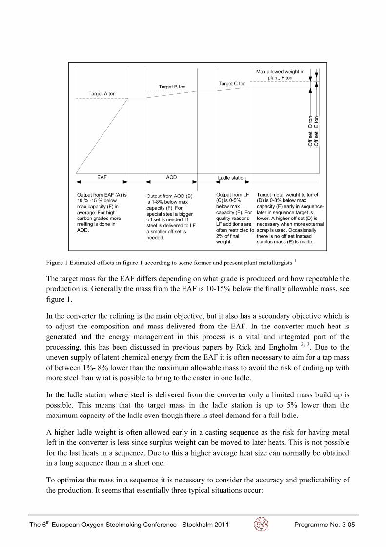
Melting enough but not too much Mass build up throughout the melt shop is made in such a way that the desired mass is met for the ladle that is delivered to the turret, see figure 1. The data presented in figure 1 is based on material from plant interviews 1.
In the melt shop the main melting is done in the EAF. The metal analysis and weight after the EAF is mainly a consequence of how scrap was loaded in the scrap yard. Some adjustments and improvements are made in the furnace but its primary objective is efficient melting. The uncertainty in composition and weight is a function of what raw materials was used as melting stock. Well defined industrial scrap and similar targets from one heat to the next increase repeatability while scrap from unknown sources and a wider product range decrease it.
̸» ꬸ Û«®±°»¿² Ѩ§¹»² ͬ»»´³¿µ·²¹ ݱ²º»®»²½» ó ͬ±½µ¸±´³ îðïï Ю±¹®¿³³» Ò±ò íóðë
Ѻº
»¬
ܬ±
²
ÛßÚ ßÑÜ Ô¿¼´» ¬¿¬·±²
Ì¿®¹»¬ ß ¬±²
Ó¿¨ ¿´´±©»¼ ©»·¹¸¬ ·²°´¿²¬ô Ú ¬±²
Ì¿®¹»¬ Þ ¬±²Ì¿®¹»¬ Ý ¬±²
Ñ«¬°«¬ º®±³ ÛßÚ øß÷ ·ïð û óïë û ¾»´±©³¿¨ ½¿°¿½·¬§ øÚ÷ ·²¿ª»®¿¹»ò Ú±® ¸·¹¸½¿®¾±² ¹®¿¼» ³±®»³»´¬·²¹ · ¼±²» ·²ßÑÜò
Ñ«¬°«¬ º®±³ ßÑÜ øÞ÷· ïóèû ¾»´±© ³¿¨½¿°¿½·¬§ øÚ÷ò Ú±®°»½·¿´ ¬»»´ ¿ ¾·¹¹»®±ºº »¬ · ²»»¼»¼ò ׺¬»»´ · ¼»´·ª»®»¼ ¬± ÔÚ¿ ³¿´´»® ±ºº »¬ ·²»»¼»¼ò
Ñ«¬°«¬ º®±³ ÔÚøÝ÷ · ðóëû¾»´±© ³¿¨½¿°¿½·¬§ øÚ÷ò Ú±®¯«¿´·¬§ ®»¿±²ÔÚ ¿¼¼·¬·±² ¿®»±º¬»² ®»¬®·½¬»¼ ¬±îû ±º º·²¿´©»·¹¸¬ò
Ì¿®¹»¬ ³»¬¿´ ©»·¹¸¬ ¬± ¬«®®»¬øÜ÷ · ðóèû ¾»´±© ³¿¨½¿°¿½·¬§ øÚ÷ »¿®´§ ·² »¯«»²½»ó´¿¬»® ·² »¯«»²½» ¬¿®¹»¬ ·´±©»®ò ß ¸·¹¸»® ±ºº »¬ øÜ÷ ·²»½»¿®§ ©¸»² ³±®» »¨¬»®²¿´½®¿° · «»¼ò ѽ½¿·±²¿´´§¬¸»®» · ²± ±ºº »¬ ·²¬»¿¼«®°´« ³¿ øÛ÷ · ³¿¼»ò
Ѻº
»¬
Û¬±
²
Figure 1 Estimated offsets in figure 1 according to some former and present plant metallurgists 1
The target mass for the EAF differs depending on what grade is produced and how repeatable the production is. Generally the mass from the EAF is 10-15% below the finally allowable mass, see figure 1.
In the converter the refining is the main objective, but it also has a secondary objective which is to adjust the composition and mass delivered from the EAF. In the converter much heat is generated and the energy management in this process is a vital and integrated part of the processing, this has been discussed in previous papers by Rick and Engholm 2, 3. Due to the uneven supply of latent chemical energy from the EAF it is often necessary to aim for a tap mass of between 1%- 8% lower than the maximum allowable mass to avoid the risk of ending up with more steel than what is possible to bring to the caster in one ladle.
In the ladle station where steel is delivered from the converter only a limited mass build up is possible. This means that the target mass in the ladle station is up to 5% lower than the maximum capacity of the ladle even though there is steel demand for a full ladle.
A higher ladle weight is often allowed early in a casting sequence as the risk for having metal left in the converter is less since surplus weight can be moved to later heats. This is not possible for the last heats in a sequence. Due to this a higher average heat size can normally be obtained in a long sequence than in a short one.
To optimize the mass in a sequence it is necessary to consider the accuracy and predictability of the production. It seems that essentially three typical situations occur:
̸» ꬸ Û«®±°»¿² Ѩ§¹»² ͬ»»´³¿µ·²¹ ݱ²º»®»²½» ó ͬ±½µ¸±´³ îðïï Ю±¹®¿³³» Ò±ò íóðë

1) When making short sequences due to special steel production it is important to avoid making too much steel in the converter. For this type of production the raw material quality is unstable so the cooling need is varying. In this case a big off set (target steel mass 5% lower than max to the caster) is applied. Casting of up to 2% of the special steel as surplus, beside the caster occurs in this type of production.
2) When making long sequences of standard steels and using much purchased scrap a big off set (target steel mass is 5% lower than max) is applied as the risk for deviation in latent chemical heat and yield is significant. Casting of 0.2% of the steel as surplus, beside the caster also occurs in this type of production.
3) When making long sequences of standard steels and using much virgin materials and well known scrap a small off set is usually applied (target steel mass is less than 2% lower than max). Scrapping steel as surplus is unusual in this type of production.
Yield In the melt shop losses occur in different operations. Some of the losses are related to the tonnage that is produced while others are mainly a function of the number of times the operation is performed. In table 1 typical figures for these losses are displayed. The total loss estimated during interviews corresponds well with figures quoted in the literature 4.
Table 1 Estimated yields at different stations in the melt shop depending on sequence length and heat size 1.
Start mass
ton
Heats in
Sequence
EAF Yield
(%)
Ladle
Yield (%)
AOD Yield
(%)
Ladle
Yield (%)
Tundish
Yield (%)
Cas�ng
Yield (%)
Total
Yield (%)
98 10 97,0 99,5 97,1 99,0 99,4 99,0 91,5
98 3 97,0 99,5 97,1 99,0 98,5 97,8 89,6
94 10 96,9 99,5 97,0 99,0 99,4 99,0 91,4
94 3 96,9 99,5 97,0 99,0 98,4 97,7 89,3
As seen in table 1 long sequences are desired when possible as the yield is then raised. This is caused by the casting losses mainly being created during the start and end of a sequence- not during the sequence itself.
By applying the yields in table 1 on a 500 kt/year production during different conditions, total losses and treatment costs associated with the yield loss in the melt shop is estimated, see table 2. In the table the surplus metal that is created with different target mass is also estimated.
Based on table 2 it is evident that significant opportunities are available if the yield can be increased, the offset can be decreased and the surplus production removed. In addition to these benefits an improvement in accuracy in weight control in the converter and downstream can be taken advantage of by utilization of cheaper raw materials as charge material for the EAF.
̸» ꬸ Û«®±°»¿² Ѩ§¹»² ͬ»»´³¿µ·²¹ ݱ²º»®»²½» ó ͬ±½µ¸±´³ îðïï Ю±¹®¿³³» Ò±ò íóðë
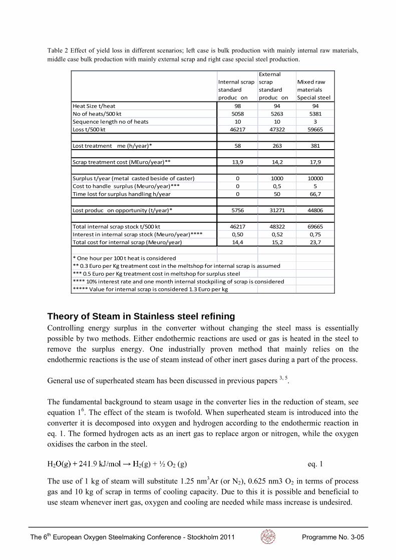
Table 2 Effect of yield loss in different scenarios; left case is bulk production with mainly internal raw materials, middle case bulk production with mainly external scrap and right case special steel production.
Internal scrap
standard
produc�on
External
scrap
standard
produc�on
Mixed raw
materials
Special steel
Heat Size t/heat 98 94 94
No of heats/500 kt 5058 5263 5381
Sequence length no of heats 10 10 3
Loss t/500 kt 46217 47322 59665
Lost treatment �me (h/year)* 58 263 381
Scrap treatment cost (MEuro/year)** 13,9 14,2 17,9
Surplus t/year (metal casted beside of caster) 0 1000 10000
Cost to handle surplus (Meuro/year)*** 0 0,5 5
Time lost for surplus handling h/year 0 50 66,7
Lost produc�on opportunity (t/year)* 5756 31271 44806
Total internal scrap stock t/500 kt 46217 48322 69665
Interest in internal scrap stock (Meuro/year)**** 0,50 0,52 0,75
Total cost for internal scrap (Meuro/year) 14,4 15,2 23,7
* One hour per 100 t heat is considered
** 0.3 Euro per Kg treatment cost in the meltshop for internal scrap is assumed
*** 0.5 Euro per Kg treatment cost in meltshop for surplus steel
**** 10% interest rate and one month internal stockpiling of scrap is considered
***** Value for internal scrap is considered 1.3 Euro per kg
Theory of Steam in Stainless steel refining Controlling energy surplus in the converter without changing the steel mass is essentially possible by two methods. Either endothermic reactions are used or gas is heated in the steel to remove the surplus energy. One industrially proven method that mainly relies on the endothermic reactions is the use of steam instead of other inert gases during a part of the process. General use of superheated steam has been discussed in previous papers 3, 5. The fundamental background to steam usage in the converter lies in the reduction of steam, see equation 16. The effect of the steam is twofold. When superheated steam is introduced into the converter it is decomposed into oxygen and hydrogen according to the endothermic reaction in eq. 1. The formed hydrogen acts as an inert gas to replace argon or nitrogen, while the oxygen oxidises the carbon in the steel. H2 2(g) + ½ O2 (g) eq. 1
The use of 1 kg of steam will substitute 1.25 nm3Ar (or N2), 0.625 nm3 O2 in terms of process gas and 10 kg of scrap in terms of cooling capacity. Due to this it is possible and beneficial to use steam whenever inert gas, oxygen and cooling are needed while mass increase is undesired.
̸» ꬸ Û«®±°»¿² Ѩ§¹»² ͬ»»´³¿µ·²¹ ݱ²º»®»²½» ó ͬ±½µ¸±´³ îðïï Ю±¹®¿³³» Ò±ò íóðë

Practical examples of steam in stainless steel making
To illustrate the advantages of using steam in the process to control the final mass in the converter some different scenarios have been simulated. The cases were calculated using the commercial software UTCAS®, described shortly below.
Models used for simulations UTCAS® is a computer system designed for converter process management. The system concept includes effective real-time process control system and tools for process design and production evaluation, see figure 2. The UTCAS® system is used for stainless steel production management, process control and process design in Outokumpus Avesta Works as well as in
Figure 2 The UTCAS® concept for process control and data management.
UTCAS® includes metallurgical models capable of determining heat and mass balance and chemical composition continuously during the process. The models forecast the final temperature and slag/metal composition based on planned gas blowing and additions. UTCAS® is also a valuable tool to design the process beforehand. It optimizes the production by controlling the process to meet final targets. The core of the models is based on Sjöbergs work 7. UTCAS® is further described in other papers by Beskow, Engholm and Rick 2, 8, 9.
Computer simulated scenarios Totally five different cases were studied. In the examples a reference case with typical mass build up according to plant design is compared with a few solutions to operate the process in case of more latent chemical heat is present in the arriving pre-melt than expected (increased Si-level).
The results from the simulations are shown in table 3. The main operator screen from UTCAS® displaying process results is shown in figure 3.
In the reference case (case no 1) 90 ton of steel with 0.2% Si and 1600 °C is used as input analysis in the converter. For case 2-5 90 t steel with 0.8% Si and 1650 °C is used. In each case
̸» ꬸ Û«®±°»¿² Ѩ§¹»² ͬ»»´³¿µ·²¹ ݱ²º»®»²½» ó ͬ±½µ¸±´³ îðïï Ю±¹®¿³³» Ò±ò íóðë

the maximum allowed temperature in the converter is 1730 °C and the objective is to make maximum 100 ton, as this is the max capacity of the casting ladle.
Figure 3 UTCAS® PD Screen displaying the process.
In the reference case blowing is done while gradually decreasing oxygen and increasing the inert gas flow, 10 ton of alloys and scrap is added and the temperature is not allowed to surpass 1730 °C. This is a typical procedure to operate an AOD.
For case 2-5 with more heat available four different solutions are compared with reference case 1 with nominal heat:
1) Reference case. 2) Temperature is allowed to reach 1820 °C, this will ruin the refractory but saves time. 3) Temperature is limited to 1730 °C and cooling is done by using more nitrogen- this is
very time consuming but solves the surplus heat problem. 4) Cooling is done using extra scrap in surplus of the desired 100 t to make 107 tons. 5) Cooling is done using superheated steam to satisfy all the desired .
As can be seen in table 3, by using steam in the process (case 5) the desired tap weight of 100 ton is met, while at the same time controlling the process temperature. This is not possible in case 2, where the final mass is controlled by allowing a higher temperature. This will lead to a faster decarburization but increase the refractory wear. Comparing with case 3, where nitrogen is used to cool the process, the time can be shortened with 20 minutes by the use of superheated steam. Cooling with metal (case 4) gives similar process time as when using superheated steam but results in too high tap mass - 107 ton. The above results clearly display the advantages of using superheated steam in the process.
̸» ꬸ Û«®±°»¿² Ѩ§¹»² ͬ»»´³¿µ·²¹ ݱ²º»®»²½» ó ͬ±½µ¸±´³ îðïï Ю±¹®¿³³» Ò±ò íóðë

Table 3 Results from computer simulations.
No Description
Mass
start
Start
temp
Start
Si Q Grade
Max
temp
Mass
final
Final
temp Time
ton ° C %
Nm3/
ton,mi
n ° C ton ° C min
1 Reference case 90 1600 0,2 1,1 304 L 1730 100 1650 55
2 Allow high temp 90 1650 0,8 1,1 304 L 1820 100 1730 58
3 Cooling with nitrogen 90 1650 0,8 1,1 304 L 1730 100 1650 82
4 Cooling with metal 90 1650 0,8 1,1 304 L 1730 107 1650 62
5 Cooling with 600 kg steam 90 1650 0,8 1,1 304 L 1730 100 1650 60
Reduc�on, deslagging and desulph takes 18 minutes
Production implications As illustrated above, the use of superheated steam can improve the yield by decreasing the risk of having to make surplus steel. This is particularly valid in two situations:
1) When special steel is made. 2) When standard steel is made using much external scrap.
Table 4 Improvement of yield loss in scenarios with high external scrap input and special steel making (middle and right case in table 2).
Mixed raw
materials
Standard
Steel
Mixed raw
materials
Special
steel
Heat Size t/heat 98 98
No of heats/500 kt 5058 5167
Sequence length no of heats 10 3
Loss t/500 kt 46217 58044
Extra treatment �me (h/year)* 58 167
Scrap treatment cost (MEuro/year)** 13,9 17,4
Surplus t/year (metal casted beside of caster) 0 0
Cost to handle surplus (Meuro/year)*** 0 0
Time lost for surplus handling h/year 0 0
Lost produc�on opportunity (t/year)* 5756 16708
Total internal scrap stock t/500 kt 46217 58044
Interest in internal scrap stock (Meuro/year)**** 0,50 0,63
Total cost for internal scrap (Meuro/year) 14,4 18,0
* One hour per 100 t heat is considered (5000 100 t heats/year is reference)
** 0.3 Euro per Kg treatment cost in the meltshop for internal scrap is assumed
*** 0.5 Euro per Kg treatment cost in meltshop for surplus steel
**** 10% interest rate and one month internal stockpiling of scrap is considered
***** Value for internal scrap is considered 1.3 Euro per kg
̸» ꬸ Û«®±°»¿² Ѩ§¹»² ͬ»»´³¿µ·²¹ ݱ²º»®»²½» ó ͬ±½µ¸±´³ îðïï Ю±¹®¿³³» Ò±ò íóðë
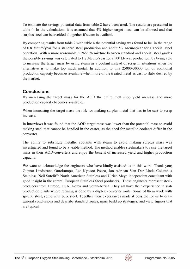
To estimate the savings potential data from table 2 have been used. The results are presented in table 4. In the calculations it is assumed that 4% higher target mass can be allowed and that surplus steel can be avoided altogether if steam is available.
By comparing results from table 2 with table 4 the potential saving was found to be in the range of 0.8 Meuro/year for a standard steel production and about 5.7 Meuro/year for a special steel operation. With a more reasonable 80%/20% mixture between standard and special steel grades the possible savings was calculated to 1.8 Meuro/year for a 500 kt/year production, by being able to increase the target mass by using steam as a coolant instead of scrap in situations when the alternative is to make too much metal. In addition to this 25000-30000 ton of additional production capacity becomes available when more of the treated metal is cast to slabs desired by the market.
Conclusions By increasing the target mass for the AOD the entire melt shop yield increase and more production capacity becomes available.
When increasing the target mass the risk for making surplus metal that has to be cast to scrap increase.
In interviews it was found that the AOD target mass was lower than the potential mass to avoid making steel that cannot be handled in the caster, as the need for metallic coolants differ in the converter.
The ability to substitute metallic coolants with steam to avoid making surplus mass was investigated and found to be a viable method. The method enables steelmakers to raise the target mass in their AOD-converters and enjoy the benefit of increased yield and higher production capacity.
We want to acknowledge the engineers who have kindly assisted us in this work. Thank you; Gunnar Lindstrand Outokumpu, Lee Kyosoo Posco, Jan Adriaan Van Der Linde Columbus Stainless, Neil Sutcliffe North American Stainless and Ulrich Meyn independent consultant with good insight in the central European Stainless Steel producers. These engineers represent steel-producers from Europe, USA, Korea and South-Africa. They all have their experience in slab production plants where refining is done by a duplex converter route. Some of them work with special steel, some with bulk steel. Together their experiences made it possible for us to draw general conclusions and describe standard routes, mass build up strategies, and yield figures that are typical.
̸» ꬸ Û«®±°»¿² Ѩ§¹»² ͬ»»´³¿µ·²¹ ݱ²º»®»²½» ó ͬ±½µ¸±´³ îðïï Ю±¹®¿³³» Ò±ò íóðë

References
1 Interviews and or questionnaires with plant metallurgists and process consultants:
Jan-Adriaan van der Linde Plant metallurgist at Columbus Stainless Gunnar Lindstrand Plant metallurgist at Outokumpu Avesta Lee Kyosoo Research Metallurgist at Posco No 3 Neil Sutcliffe Plant Metallurgist at NAS Kentucky Ulrich Meyn Consultant working for European stainless steel
producers
2 Rick, C; Engholm, M: Control and optimization of material additions throughout the AOD refining cycle. Paper presented at SteelSim in Leoben 2009.
3 Rick, C.: Strategies for Use of Superheated Steam During Stainless Steel Refining in Converters. Paper presented at AISTECH in Pittsburgh 2010.
4 http://www.worldstainless.org/NR/rdonlyres/8FD08987-E98F-4BB8-9B33-99EEF0E8F938/2425/StainlessSteelRecyclingAvailabilityofscrap.pdf
5 Rick, C; Beskow, K; Linde, J.: Steam as a Process Gas Brings Economic Benefits to Columbus Stainless. May/June 2010 Steel Times International. P.20.
6 O. Kubaschewski, and C.B. Alcock (1979). Metallurgical Thermochemistry, 5th edition, Pergamon Press, New York. 7 -thesis from the Royal institute of Technology, Stockholm 1995.
8 Engholm, M: UTCAS the complete system for converter process management; Nordic Steel and Mining Review. (2008/03), P. 125
9 Rick, C; Engholm, M; Beskow, K: Value Creation in Simulated Steel. Paper presented at SteelSim in Dusseldorf 2011.
̸» ꬸ Û«®±°»¿² Ѩ§¹»² ͬ»»´³¿µ·²¹ ݱ²º»®»²½» ó ͬ±½µ¸±´³ îðïï Ю±¹®¿³³» Ò±ò íóðë