generac power systems, inc. · 2020. 4. 14. · installation guidelines for spark-ignited...
TRANSCRIPT

Installation GuidelinesSpark-Ignited Stationary Generators
Protector Series 22 kW to 60 kW
SAVE THIS MANUAL FOR FUTURE REFERENCE
Para español , visita: http://www.generac.com/service-support/product-support-lookupPour le français, visiter : http://www.generac.com/service-support/product-support-lookup
®
Register your Generac product at:WWW.GENERAC.COM
1-888-GENERAC(888-436-3722)
(000209b)
WARNINGLoss of life. This product is not intended to be used in a critical life support application. Failure to adhere to this warning could result in death or serious injury.

ii Installation Guidelines For Spark-Ignited Stationary Generators
Use this page to record important information about this generator.
Model:
Serial:
Prod Date Week:
Volts:
LPV Amps:
NG Amps:
Hz:
Phase:
Controller P/N:
Record the information found on the unit data label on this page. For location of the unit data label, see owner’s manual. The unit has a label plate affixed to the inside partition, to the left of the control panel console. Always supply the complete model and serial numbers of the unit when contacting an Independent Authorized Service Dealer (IASD) about parts and service.Operation and Maintenance: Correct maintenance and care of the generator ensures a minimum number of prob-lems and keeps operating expenses at a minimum. It is the operator’s responsibility to perform all safety inspections, to verify all maintenance for safe operation is performed promptly, and to have the equipment inspected periodically by an IASD. Normal maintenance, service, and replacement of parts are the responsibility of the owner/operator and are not considered defects in materials or workmanship within the terms of the warranty. Individual operating habits and usage may contribute to the need for additional maintenance or service.When the generator requires servicing or repairs, Generac recommends contacting an IASD for assistance. Authorized service technicians are factory-trained and are capable of handling all service needs. To locate the nearest IASD, please visit the dealer locator at:www.generac.com/Service/DealerLocator/.
(000393a)
WARNINGCANCER AND REPRODUCTIVE HARM
www.P65Warnings.ca.gov.

Table of Contents
Section 1: Safety Rules & GeneralInformationIntroduction ..........................................................1
Read This Manual Thoroughly ....................................1
Safety Rules .........................................................1How to Obtain Service .................................................1
General Hazards ..................................................2Exhaust Hazards ..................................................3Electrical Hazards ................................................3Fire Hazards .........................................................3Explosion Hazards ...............................................4Lifting Hazards .....................................................4Battery Hazards ...................................................4General Rules .......................................................5
Before You Begin ........................................................5Standards Index ..........................................................6
Section 2: Installation PlanningIntroduction ..........................................................7Unit Drawings .......................................................7
Installation Drawings ...................................................7Wiring Diagrams ..........................................................7
Receiving ..............................................................7Receiving and Unpacking ............................................7Inspection ....................................................................7
Storage Before Installation .................................7Long Term Storage .....................................................7Short Term Storage .....................................................7
Lifting ....................................................................7Generator Location ..............................................8
General Location Guidelines .......................................8Weather Considerations ..............................................8
Section 3: Site Selection and PreparationSite Selection .......................................................9Carbon Monoxide ................................................9
Carbon Monoxide Detectors ........................................9Potential CO Entry Points ..........................................10Protect the Structure .................................................10
Fire Prevention ...................................................11Distance Requirements .............................................11Fire Codes, Standards, and Guidelines ....................12Generator Maintenance .............................................12
Fresh Air for Ventilation and Cooling ..............13
Water Ingress Avoidance ................................. 13Proximity to Utilities .......................................... 13Transportation Recommendations .................. 13Site Preparation ................................................. 13
Generator Foundation ...............................................13Concrete Pad ............................................................13Dimensions ................................................................13Stub-Up Area .............................................................14
Mounting ............................................................ 14Fixed Foundation .......................................................14Connections ..............................................................14
Placement on Roofs, Platforms, and Other Supporting Structures ............................ 14
Section 4: Gaseous Fuel SystemsFuel Requirements and Recommendations ... 15
BTU Content ..............................................................15Fuel Pressure ............................................................15
Fuel System Conversion .................................. 15Gaseous Fuel Properties .................................. 15
Natural Gas ...............................................................15Liquid Propane Gas ...................................................16
Definitions .......................................................... 16Gaseous Fuel Systems ..................................... 17
NG System ................................................................17Flexible Fuel Line ......................................................17Primary Regulator Outlet ...........................................17LP Gas System .........................................................19Sediment Trap ...........................................................19
Fuel Pressure Regulators ................................. 20General ......................................................................20Best Practices ...........................................................20Operating Fuel Pressure ...........................................20Engine Fuel Consumption .........................................20Fuel Pressure Regulator Sizing .................................21Recommended Fuel Pressure Regulators ................21Primary Fuel Pressure Regulator ..............................21
Pipe Sizing Considerations .............................. 22General ......................................................................22
Sizing LP Tanks for LP Gas Withdrawal ......... 23Final Operating Test .......................................... 26
Fuel Shutoff Valve .....................................................26Fuel Pressure Test Port Location ..............................26Final Test Procedure .................................................27
Installation Guidelines For Spark-Ignited Stationary Generators iii

Section 5: Electrical SystemGeneral Information ...........................................29Connecting Generator Feeder Conductors .....29Connecting Control Circuit Wires ....................30Removing Rear Panel and Stub-Up Cover ......30Typical Load Leads and Control Wiring in Stub-Up ...........................................................30Customer Load Wiring ......................................30Control Wiring Connections .............................31
RTS Series Transfer Switch With T1 Fuse/Connection ....................................................... 31Two-Wire Start .......................................................... 32
Optional Accessory Power ...............................33Installing Stub-Up Cover and Rear Panel ........33Transfer Switch Location ..................................33Battery ................................................................33
General Safety Precautions ...................................... 33Battery Requirements ............................................... 34Battery Installation .................................................... 34
Section 6: Control Panel Startup / TestingControl Panel Interface .....................................35
Using the AUTO/MANUAL/OFF Buttons .................. 35
Generator Setup .................................................35Setting The Exercise Timer ....................................... 35
Before Initial Startup .........................................36Install Wizard ............................................................ 36Interconnect System Self Test Feature ..................... 36Before starting, complete the following: .................... 36
Checking Manual Transfer Switch Operation ............................................................36Activate Unit .......................................................38Operational Checks ...........................................39
Electrical Checks ...................................................... 39Testing Generator Under Load ................................. 39Testing Auxiliary Shutdown Switch Operation .......... 40Checking Automatic Operation ................................. 40
Installation Summary ........................................40Shutting Generator Down While Under Load or During a Utility Outage ........................41
Section 7: Installation ChecklistsSafety Checklist ................................................. 43Installation Planning Checklist ........................ 43Foundations and Mounting Checklist ............. 43Ventilation System Checklist ........................... 44Exhaust System Checklist ................................ 44Gaseous Fuel System Checklist ...................... 44Electrical System Checklist .............................. 45Oil Maintainer System Checklist ...................... 45
Section 8: Lube Oil Maintainer SystemLube Oil Maintainer System ............................. 47
Description ................................................................ 47Fill Oil Supply Tank ................................................... 47Test Functionality ...................................................... 47Oil Shutoff Valve ....................................................... 48
Section 9: Troubleshooting/Quick Reference Guide
Troubleshooting ................................................ 49Quick Reference Guide ..................................... 50
Section 10: Accessories
Section 11: Installation Drawings0K8420-D 25/30 kW (1.5 L) Page 1 of 2 ............ 550K8420-D 25/30 kW (1.5 L) Page 2 of 2 ............ 560K8624-D 22/27 kW (2.4 L) Page 1 of 2 ............ 570K8624-D 22/27 kW (2.4 L) Page 2 of 2 ............ 580K8636-C 36/45 kW (2.4 L) Page 1 of 2 ............ 590K8636-C 36/45 kW (2.4 L) Page 2 of 2 ............ 600K9268-E 32/38 kW (2.4 L) Page 1 of 2 ............ 610K9268-E 32/38 kW (2.4 L) Page 2 of 2 ............ 620L2090-C 60 kW (2.4 L) Page 1 of 2 ................. 630L2090-C 60 kW (2.4 L) Page 2 of 2 ................. 640K9243-C 48 kW (5.4 L) Page 1 of 2 ................. 650K9243-C 48 kW (5.4 L) Page 2 of 2 ................. 66Alternator AC Lead Connections ..................... 67
Four-Lead, Single-Phase Stator ............................... 67
Alternator Power Winding Connections ......... 67Three-Phase Alternators (“Y” Configuration) ............ 67Three-Phase Alternators (“Delta” Configuration) ...... 68
Alternator Wiring Diagram ................................ 69
iv Installation Guidelines For Spark-Ignited Stationary Generators

Safety Rules & General Information
Section 1: Safety Rules & General InformationIntroductionThank you for purchasing this compact, high perfor-mance, liquid-cooled, engine-driven generator. It is designed to automatically supply electrical power to oper-ate critical loads during a utility power failure.This unit is factory installed in an all-weather enclosure intended exclusively for outdoor installation. This genera-tor will operate using either vapor withdrawn liquid pro-pane (LP gas) or natural gas (NG).
NOTE: This generator is suitable for supplying typical residential and commercial loads such as induction motors (sump pumps, refrigerators, air conditioners, fur-naces, etc.), electronic components (computer, monitor, TV, etc.), lighting loads, and microwaves, when sized cor-rectly.
The information in this manual is accurate based on products produced at the time of publication. The manu-facturer reserves the right to make technical updates, corrections, and product revisions at any time without notice.
Read This Manual Thoroughly
If any section of this manual is not understood, contact the nearest Independent Authorized Service Dealer (IASD) or Generac Customer Service at 1-888-436-3722 (1-888-GENERAC), or visit www.generac.com for start-ing, operating, and servicing procedures. The owner is responsible for proper maintenance and safe use of the unit.SAVE THESE INSTRUCTIONS for future reference. This manual contains important instructions that must be fol-lowed during placement, operation, and maintenance of the unit and its components. Always supply this manual to any individual that will use this unit, and instruct them on how to correctly start, operate, and stop the unit in case of emergency.
Safety RulesThe manufacturer cannot anticipate every possible cir-cumstance that might involve a hazard. The alerts in this manual, and on tags and decals affixed to the unit, are not all inclusive. If using a procedure, work method, or
operating technique that the manufacturer does not spe-cifically recommend, verify that it is safe for others and does not render the equipment unsafe.Throughout this publication, and on tags and decals affixed to the unit, DANGER, WARNING, CAUTION, and NOTE blocks are used to alert personnel to special instructions about a particular operation that may be haz-ardous if performed incorrectly or carelessly. Observe them carefully. Alert definitions are as follows:
NOTE: Notes contain additional information important to a procedure and will be found within the regular text of this manual.
These safety alerts cannot eliminate the hazards that they indicate. Common sense and strict compliance with the special instructions while performing the action or service are essential to preventing accidents.
How to Obtain ServiceWhen the unit requires servicing or repairs, contact Gen-erac Customer Service at 1-888-GENERAC (1-888-436-3722) or visit www.generac.com for assistance. When contacting Generac Customer Service about parts and service, always supply the complete model and serial number of the unit as given on its data decal located on the unit. Record the model and serial numbers in the spaces provided on the front cover of this manual.
(000100a)
WARNINGConsult Manual. Read and understand manualcompletely before using product. Failure to completely understand manual and productcould result in death or serious injury.
(000001)
DANGERIndicates a hazardous situation which, if not avoided, will result in death or serious injury.
(000002)
WARNINGIndicates a hazardous situation which, if not avoided,could result in death or serious injury.
(000003)
CAUTIONIndicates a hazardous situation which, if not avoided,could result in minor or moderate injury.
Installation Guidelines For Spark-Ignited Stationary Generators 1

Safety Rules & General Information
General Hazards
Inspect the generator regularly, and contact an IASD for parts needing repair or replacement.
(000190)
DANGERLoss of life. Property damage. Installation must always comply with applicable codes, standards, laws and regulations. Failure to do so will result in death or serious injury.
Automatic start-up. Disconnect utility power and render unit inoperable before working on unit. Failure to do so will result in death or serious injury.
(000191)
DANGER
(000209b)
WARNINGLoss of life. This product is not intended to be used in a critical life support application. Failure to adhere to this warning could result in death or serious injury.
WARNINGEquipment damage. This unit is not intended for use as a prime power source. It is intended for use as an intermediate power supply in the event of temporary power outage only. Doing so could result in death, serious injury, and equipment damage. (000247a)
(000187)
WARNINGElectrocution. Potentially lethal voltages are generatedby this equipment. Render the equipment safe beforeattempting repairs or maintenance. Failure to do socould result in death or serious injury.
(000130)
WARNINGAccidental Start-up. Disconnect the negative battery cable, then the positive battery cable when working on unit. Failure to do so could result in death or serious injury.
(000182a)
WARNINGEquipment damage. Only qualified service personnel may install, operate, and maintain this equipment. Failure to follow proper installation requirements could result in death, serious injury, and equipment or property damage.
(000155a)
WARNINGElectric shock. Only a trained and licensed electrician should perform wiring and connections to unit. Failure to follow proper installation requirements could result in death, serious injury, and equipment or property damage.
(000115)
WARNINGMoving Parts. Do not wear jewelry when starting or operating this product. Wearing jewelry while starting or operating this product could result in death or serious injury.
(000111)
WARNINGMoving Parts. Keep clothing, hair, and appendages away from moving parts. Failure to do so could result in death or serious injury.
(000108)
WARNINGHot Surfaces. When operating machine, do not touch hot surfaces. Keep machine away from combustibles during use. Hot surfaces could result in severe burns or fire.
(000146)
WARNINGEquipment and property damage. Do not alter construction of, installation, or block ventilation for generator. Failure to do so could result in unsafe operation or damage to the generator.
WARNINGRisk of injury. Do not operate or service this machine if not fully alert. Fatigue can impair the ability to service this equipment and could result in death or serious injury.
(000215)
WARNINGInjury and equipment damage. Do not use generator as a step. Doing so could result in falling, damaged parts, unsafe equipment operation, and could result in death or serious injury.
(000216)
2 Installation Guidelines For Spark-Ignited Stationary Generators

Safety Rules & General Information
Exhaust Hazards
Electrical HazardsFire Hazards
Asphyxiation. Running engines produce carbon monoxide, a colorless, odorless, poisonous gas. Carbon monoxide, if not avoided, will result in death or serious injury.
(000103)
DANGER
(000178a)
Asphyxiation. Always use a battery operated carbon monoxide alarm indoors and installed according to the manufacturer’s instructions. Failure to do so could result in death or serious injury.
WARNING
WARNINGFire hazard. Do not obstruct cooling and
ventilating airflow around the generator. Inadequate ventilation could result in fire hazard, possible equipment damage, death or serious injury.
(000217)
(000144)
DANGERElectrocution. Contact with bare wires, terminals, and connections while generator is running will result in death or serious injury.
(000150)
DANGERElectrocution. Never connect this unit to the electrical system of any building unless a licensed electrician has installed an approved transfer switch. Failure to do so will result in death or serious injury.
(000237)
DANGERElectrical backfeed. Use only approved switchgear to isolate generator from the normal power source.Failure to do so will result in death, serious injury, and equipment damage.
(000152)
DANGERElectrocution. Verify electrical system isproperly grounded before applying power.Failure to do so will result in death or seriousinjury.
(000188)
DANGERElectrocution. Do not wear jewelry while working on this equipment. Doing so will result in death or serious injury.
(000104)
DANGERElectrocution. Water contact with a power source, if not avoided, will result in death or serious injury.
(000145)
DANGERElectrocution. In the event of electrical accident, immediately shut power OFF. Use non-conductive implements to free victim from live conductor. Apply first aid and get medical help. Failure to do so will result in death or serious injury.
WARNINGFire hazard. Do not obstruct cooling and
ventilating airflow around the generator. Inadequate ventilation could result in fire hazard, possible equipment damage, death or serious injury.
(000217)
WARNING
(000218)
Fire and explosion. Installation must comply with all local, state, and national electrical building codes. Noncompliance could result in unsafe operation, equipment damage, death, or serious injury.
WARNINGFire hazard. Use only fully-charged fire
(000219)
extinguishers rated “ABC” by the NFPA. Discharged or improperly rated fire extinguishers will not extinguish electrical fires in automatic standby generators.
(000100a)
WARNINGConsult Manual. Read and understand manualcompletely before using product. Failure to completely understand manual and productcould result in death or serious injury.
Installation Guidelines For Spark-Ignited Stationary Generators 3

Safety Rules & General Information
Comply with regulations the Occupational Safety and Health Administration (OSHA) has established, or with equivalent standards. Also, verify that the unit is applied, used, and maintained in accordance with the manufac-turer's instructions and recommendations. Do nothing that might alter safe application/usage and render the unit in noncompliance with the aforementioned codes, standards, laws, and regulations.
Explosion Hazards
Lifting Hazards
Battery Hazards
WARNING
(000257)
Electrocution. Refer to local codes and standards for safety equipment required when working with a live electrical system. Failure to use required safety equipment could result in death or serious injury.
(000147)
WARNINGRisk of Fire. Unit must be positioned in amanner that prevents combustible materialaccumulation underneath. Failure to do socould result in death or serious injury.
(000192)
DANGERExplosion and fire. Fuel and vapors are extremelyflammable and explosive. No leakage of fuel ispermitted. Keep fire and spark away. Failure to doso will result in death or serious injury.
(000151a)
DANGERExplosion and fire. Connection of fuel source must be completed by a qualified professional technician or contractor. Incorrect installation of this unit will result in death, serious injury, and property and equipment damage.
(000174)
DANGERRisk of fire. Allow fuel spills to completely dry before starting engine. Failure to do so will result in death or serious injury.
(000110)
WARNINGRisk of Fire. Hot surfaces could ignite combustibles, resulting in fire. Fire could result in death or serious injury.
DANGER
(000245)
Risk of electrocution. Avoid touching overhead power lines when lifting or hoisting generator. Failure to do so will result in death or serious injury.
WARNINGPersonal injury. Excessive weight. Use only appropriate lifting eyes and lifting equipment to lift unit. Improper lifting techniques could result in equipment damage, death or serious injury.
(000224)
WARNINGPersonal injury. Failure to properly connect lifting cables, chains, or straps could result in death, serious injury, or property damage.
(000346)
WARNINGPersonal Injury. Do not use lifting hook if there are signs of damage or corrosion. Doing so could result in death, serious injury, or property damage.
(000349)
WARNINGPersonal Injury. Do not use lifting eye if there are signs of damage or corrosion. Doing socould result in death, serious injury, or property damage.
(000433)
WARNINGPersonal Injury. Verify all fasteners are properly tightened prior to lifting unit. Failure to do so could result in death, serious injury, or property damage.
(000351)
(000188)
DANGERElectrocution. Do not wear jewelry while working on this equipment. Doing so will result in death or serious injury.
4 Installation Guidelines For Spark-Ignited Stationary Generators

Safety Rules & General Information
Always recycle batteries in accordance with local laws and regulations. Contact your local solid waste collection site or recycling facility to obtain information on local recycling processes. For more information on battery recycling, visit the Battery Council International website at: http://batterycouncil.org
General Rules
• Follow all safety precautions in the owner’s man-ual, installation guidelines, and other documents included with the equipment.
• See NFPA 70E for safety equipment required when working with a live system.
• Never energize a new system without opening all disconnects and breakers.
• Always consult local code for additional require-ments for the area where unit is being installed.
• Incorrect installation can result in personal injury and damage to the generator. It may also suspend or void the warranty. All instructions listed below must be followed including location clearances and pipe sizes.
Before You Begin• Contact local inspector or city hall to be aware of all
federal, state, and local codes which could impact installation. Secure all required permits before installing.
• Fully comply with all relevant NEC, NFPA, and OSHA standards, as well as all federal, state, and local building and electric codes. This unit must be installed in accordance with current NFPA 37 and NFPA 70 standards, and any other federal, state,
(000162)
WARNINGExplosion. Do not dispose of batteries in a fire. Batteries are explosive. Electrolyte solution can cause burns and blindness. If electrolyte contacts skin or eyes, flush with water and seek immediate medical attention.
(000137a)
WARNINGExplosion. Batteries emit explosive gases while charging. Keep fire and spark away. Wear protective gear when working with batteries. Failure to do so could result in death or serious injury.
(000164)
WARNINGElectrical shock. Disconnect battery groundterminal before working on battery or batterywires. Failure to do so could result in death or serious injury.
(000138a)
WARNINGRisk of burns. Batteries contain sulfuric acid and can cause severe chemical burns. Wear protective gear when working with batteries. Failure to do so could result in death or serious injury.
(000163a)
WARNINGRisk of burn. Do not open or mutilate batteries. Batteries contain electrolyte solution which can cause burns and blindness. If electrolyte contacts skin or eyes, flush with water and seek immediate medical attention.
WARNING
(000228)
Environmental Hazard. Always recycle batteries at an official recycling center in accordance with all local laws and regulations. Failure to do so could result in environmental damage, death, or serious injury.
(000190)
DANGERLoss of life. Property damage. Installation must always comply with applicable codes, standards, laws and regulations. Failure to do so will result in death or serious injury.
(000237)
DANGERElectrical backfeed. Use only approved switchgear to isolate generator from the normal power source.Failure to do so will result in death, serious injury, and equipment damage.
(000182a)
WARNINGEquipment damage. Only qualified service personnel may install, operate, and maintain this equipment. Failure to follow proper installation requirements could result in death, serious injury, and equipment or property damage.
WARNING
(000257)
Electrocution. Refer to local codes and standards for safety equipment required when working with a live electrical system. Failure to use required safety equipment could result in death or serious injury.
Installation Guidelines For Spark-Ignited Stationary Generators 5

Safety Rules & General Information
and local codes for minimum distances from other structures.
• Verify capacity of NG meter or LP tank in regards to providing sufficient fuel for both the unit and other household and operating appliances.
Standards Index
Strictly comply with all applicable national, state, and local laws, as well as codes or regulations pertaining to the installation of this engine-generator power system. Use the most current version of applicable codes or stan-dards relevant to the local jurisdiction, generator used, and installation site.
NOTE: Not all codes apply to all products and this list is not all-inclusive. In the absence of pertinent local laws and standards, the following publications may be used as a guide (these apply to localities which recognize NFPA and IBC).
1. National Fire Protection Association (NFPA) 70: The NATIONAL ELECTRIC CODE (NEC) *
2. NFPA 10: Standard for Portable Fire Extinguishers *3. NFPA 30: Flammable and Combustible Liquids
Code *4. NFPA 37: Standard for Stationary Combustion
Engines and Gas Turbines *5. NFPA 54: National Fuel Gas Code *6. NFPA 58: Standard for Storage and Handling Of
Liquefied Petroleum Gases *7. NFPA 68: Standard On Explosion Protection By
Deflagration Venting *8. NFPA 70E: Standard For Electrical Safety In The
Workplace *9. NFPA 211: Standard for Chimneys, Fireplaces,
Vents, and Solid Fuel Burning Appliances *10. NFPA 220: Standard on Types of Building Con-
struction *11. NFPA 5000: Building Code *12. ICC IFGC: International Fuel Gas Code13. International Building Code **14. Agricultural Wiring Handbook ***15. Article X, NATIONAL BUILDING CODE16. ASAE EP-364.2 Installation and Maintenance of
Farm Standby Electric Power ****
This list is not all-inclusive. Check with the Authority Hav-ing Local Jurisdiction (AHJ) for any local codes or stan-dards which may be applicable to your jurisdiction. The above listed standards are available from the following internet sources:* www.nfpa.org** www.iccsafe.org*** www.rerc.org Rural Electricity Resource Council P.O. Box 309 Wilmington, OH 45177-0309**** www.asabe.org American Society of Agricultural & Biological Engineers 2950 Niles Road, St. Joseph, MI 49085
(000209b)
WARNINGLoss of life. This product is not intended to be used in a critical life support application. Failure to adhere to this warning could result in death or serious injury.
6 Installation Guidelines For Spark-Ignited Stationary Generators

Installation Planning
Section 2: Installation PlanningIntroduction
IMPORTANT NOTE: Connecting this generator to an electrical system normally supplied by an electric utility shall be by means of a transfer switch, so as to isolate the electric system from the utility distribu-tion system when the generator is operating. Failure to isolate the electric system by these means will result in damage to generator and may also result in injury or death to utility workers due to backfeed of electrical energy.
NOTE: Only an IASD or qualified, competent installation contractors, or electricians thoroughly familiar with appli-cable codes, standards, and regulations should install this standby electric power system. The installation must strictly comply with all codes, standards, and regulations pertaining to installation.
Unit DrawingsInstallation DrawingsSee Installation Drawings. Installation drawings show weights, dimensions, clearances, exhaust details, con-nection locations, wiring stub-ups, lifting locations, and other information. Use the unit specific installation draw-ings when designing a site installation plan. Thoroughly read NOTES section of each drawing for important details.
Wiring DiagramsWiring and schematic diagrams show connection points for control wiring, load wiring, and any service power sup-ply required for battery chargers, block heaters, etc. Always use the unit specific wiring diagrams during plan-ning and installation.
ReceivingReceiving and UnpackingWhen applicable, handle shipping cartons and crates with care to avoid damage. Store and unpack cartons with correct side up, as noted by label on shipping carton.
InspectionCarefully inspect generator and all contents of cartons for any damage that may have occurred during shipment. See shipping documentation for any provisions or guid-ance when damage is incurred. Correct all damage or deficiencies before installing generator.
Storage Before InstallationLong Term StorageIf unit will be stored (or installed and not started) for six months or more, preserve in accordance with the manu-facturer’s instructions. Contact an IASD to obtain the Long Term Preservation and Storage Manual (Part No. 0G4018) and the Preservation Checklist (Part No. 0G4018A).
Short Term StorageProceed as follows if unit will be stored (or installed and not started) for less than six months:
• All units are provided with an enclosure.• Place unit on a smooth flat surface. Do not leave
unit on shipping pallet, as it leaves the bottom open for entry of dirt, debris, insects, rodents, etc.
• If applicable, cover any exhaust system openings.• Leave plastic plugs in fuel connection points. • Use anti-rodent plugs and other enclosure features
to prevent entry of birds, small animals, and foreign objects.
Lifting
Generators weighing more than 900 lbs (408 kg) require the correct tools, equipment, and qualified personnel to be used in all phases of handling and unpacking.To verify personal safety and prevent damage to the unit, use only correctly sized equipment intended for safe rig-ging, lifting, and moving of heavy machinery.
(000237)
DANGERElectrical backfeed. Use only approved switchgear to isolate generator from the normal power source.Failure to do so will result in death, serious injury, and equipment damage.
DANGER
(000245)
Risk of electrocution. Avoid touching overhead power lines when lifting or hoisting generator. Failure to do so will result in death or serious injury.
WARNINGPersonal injury. Excessive weight. Use only appropriate lifting eyes and lifting equipment to lift unit. Improper lifting techniques could result in equipment damage, death or serious injury.
(000224)
Installation Guidelines For Spark-Ignited Stationary Generators 7

Installation Planning
Use a spreader bar to prevent damage to unit. Failure to use a spreader bar will result in scratches and dam-age to painted surfaces. See Figure 2-1. Installation drawings show lifting points for rigging and lifting purposes. Always attach lifting and rigging devices at designated points only. Do not use lift-ing points of the engine or alternator to move generator.
Figure 2-1. Lifting Points (Four Places)
Generator LocationLocate generator so it is readily accessible for mainte-nance, repair, and firefighting purposes. Comply with code requirements for minimum distance from combusti-ble walls and building openings.
General Location GuidelinesConsider the following:
• The generator, in its protective enclosure, must be installed outdoors.
• Supporting structure must be adequate for genera-tor and its accessories.
• Verify installation site is clean, dry, not subject to flooding, and provided with adequate drainage in event of heavy rains.
• Verify installation site permits noise and vibration to be effectively isolated.
• Verify installation site provides easy, ready access to generator for maintenance, repair, and emer-gency response purposes.
• See Figure 3-1. Keep a minimum clear working space around each side of the generator to facili-tate service or maintenance. See NEC Article 110.26 for clarification.
• Verify installation site permits engine exhaust gases to be safely evacuated from inhabited or occupied areas. Consider the direction of prevail-ing winds to prevent exhaust gases from being car-
ried back to engine area or to fresh air intake vents of nearby buildings.
• Installation site must allow for provision of an ade-quate fuel supply.
• Verify installation site permits sufficient air flow for cooling and ventilation. Consider proximity of any walls, fences, or other noise abatement or security barriers. Do NOT face radiator discharge end of the enclosure into prevailing wind.
• Consider cold weather kit options and accessories for generator in cold weather locations.
• Verify unit is securely fastened to mounting pad to prevent movement caused by vibration.
• Verify all electrical connections have flexible sec-tions to isolate vibration.
• Verify fuel pressure and pipe is sized correctly and has the appropriate flex hose.
NOTE: Failure to comply with site selection guidelines can result in damage to generator or surrounding area and may cause warranty to be suspended or voided. Extra repair labor or equipment may not be covered under warranty if service access is difficult or restricted.
Weather ConsiderationsConsider local weather conditions during installation. There are various accessories available to promote fast, reliable starting and operation regardless of local climatic conditions. Optional cold weather kits make engine start-ing more dependable and reliable.
000386
8 Installation Guidelines For Spark-Ignited Stationary Generators
Site Selection and Preparation
Section 3: Site Selection and PreparationSite SelectionSite selection is critical for safe generator operation. It is important to discuss these factors with the installer when selecting a site for generator installation:
• Carbon monoxide• Fire prevention• Fresh air for ventilation and cooling• Water ingress prevention• Proximity to utilities• Suitable mounting surface
The following pages describe each of these factors in detail.
NOTE: The term “structure” is used throughout this sec-tion to describe the home or building where generator is being installed. Illustrations depict a typical residential home. However, instructions and recommendations pre-sented in this section apply to all structures regardless of type.
Carbon Monoxide
IMPORTANT NOTE: Move to fresh air immediately and seek medical attention if you feel sick, dizzy, or weak while the generator is running or after it stops.
Generator exhaust contains carbon monoxide (CO)—a poisonous, potentially lethal gas that cannot be seen or smelled. The generator must be installed in a well venti-lated area away from windows, doors, and openings. The selected location should not allow exhaust gases to be drawn into structures where people or animals may be present.
Carbon Monoxide DetectorsSee Figure 3-1. CO detectors (K) must be installed and used to monitor for CO and to warn individuals about the presence of CO. CO detectors must be installed and tested in accordance with the CO detector manufac-turer’s instructions and warnings. Contact local building inspection department for any applicable requirements concerning CO detectors. See NFPA 72, National Fire Alarm and Signaling Code, and Section R315 in the ICC International Residential Code for more information.
IMPORTANT NOTE: Common smoke alarms do NOT detect CO gas. Do not rely on smoke alarms to pro-tect residents or animals from CO. The only way to detect CO is to have functioning CO alarms.
Asphyxiation. Running engines produce carbon monoxide, a colorless, odorless, poisonous gas. Carbon monoxide, if not avoided, will result in death or serious injury.
(000103)
DANGER
Installation Guidelines For Spark-Ignited Stationary Generators 9

Site Selection and Preparation
Potential CO Entry PointsSee Figure 3-1. Generator exhaust can enter a structure through large openings, such as windows and doors. However, exhaust and CO can also seep into the struc-ture through smaller, less obvious openings.
Protect the StructureVerify structure itself is correctly caulked and sealed to prevent air from leaking in or out. Voids, cracks, or open-ings around windows, doors, soffits, pipes, and vents can allow exhaust gas to be drawn into the structure. Some examples of potential entry points are described and included in, but not limited to, the accompanying table.
Figure 3-1. Carbon Monoxide—Potential Entry Points
ID Entry Point Description / Comments
A Windows and doors Architectural details which can be (or are) opened to admit fresh air into the structure.
B Garage door CO can leak into garage if door is open, or does not seal correctly when closed.
C Attic vent Attic vents, ridge vents, crawl space vents, and soffit vents can all admit generator exhaust.
D Basement windows Windows or hatches allowing ventilation to or from lower level of a structure.
E Furnace intake / exhaust vent
Air intake and exhaust pipes for furnace.
F Wall cracks Includes (but not limited to) cracks in wall, foundation, mortar, or air gaps around doors, windows, and pipes. See Protect the Structure.
G Dryer vent Exhaust duct for clothes dryer.
H Airflow restrictions Structural corners and locations with heavy vegetation restrict airflow. Exhaust gases can collect in such areas.
J Make up air system
IMPORTANT NOTE: Mechanical and gravity outdoor air intake openings for HVAC supply air systems shall be located not less than 10 feet (3048mm) horizontally from the generator enclosure. See Section 401 in the ICC Mechanical Code for any additional requirements.
A
K
B
A
C
G
A
A
A FD
E
A
HA
C
009327
J
10 Installation Guidelines For Spark-Ignited Stationary Generators
Site Selection and Preparation
Installation Guidelines For Spark-Ignited Stationary Generators 11
Fire PreventionThe generator must be installed at a safe distance away from combustible materials. Engine, alternator, and exhaust system components become very hot during operation. Fire risk increases if unit is not correctly venti-lated, is not correctly maintained, operates too close to combustible materials, or if fuel leaks exist. Also, accu-mulations of flammable debris within or outside the gen-erator enclosure may ignite.
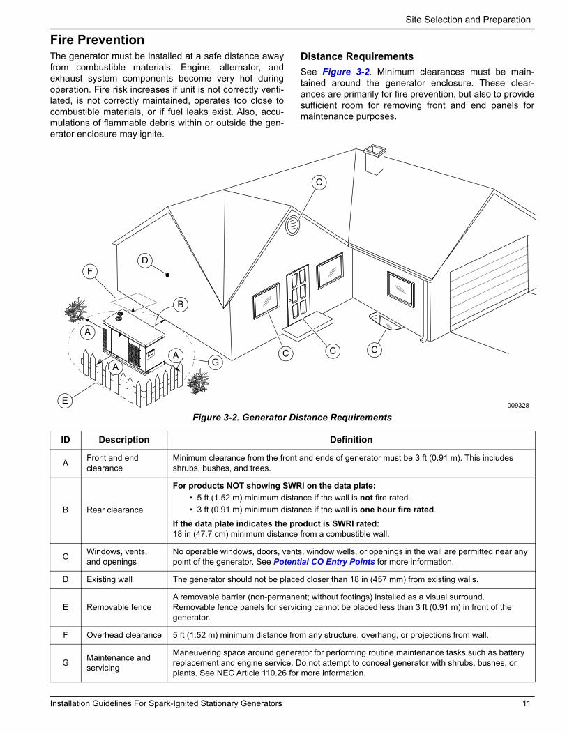
Distance RequirementsSee Figure 3-2. Minimum clearances must be main-tained around the generator enclosure. These clear-ances are primarily for fire prevention, but also to provide sufficient room for removing front and end panels for maintenance purposes.
Figure 3-2. Generator Distance Requirements
CA
A
D
E
G
A
C
C C
009328
F
B
ID Description Definition
A Front and end clearance
Minimum clearance from the front and ends of generator must be 3 ft (0.91 m). This includes shrubs, bushes, and trees.
B Rear clearance
For products NOT showing SWRI on the data plate:• 5 ft (1.52 m) minimum distance if the wall is not fire rated.• 3 ft (0.91 m) minimum distance if the wall is one hour fire rated.
If the data plate indicates the product is SWRI rated:18 in (47.7 cm) minimum distance from a combustible wall.
C Windows, vents, and openings
No operable windows, doors, vents, window wells, or openings in the wall are permitted near any point of the generator. See Potential CO Entry Points for more information.
D Existing wall The generator should not be placed closer than 18 in (457 mm) from existing walls.
E Removable fenceA removable barrier (non-permanent; without footings) installed as a visual surround.Removable fence panels for servicing cannot be placed less than 3 ft (0.91 m) in front of the generator.
F Overhead clearance 5 ft (1.52 m) minimum distance from any structure, overhang, or projections from wall.
G Maintenance and servicing
Maneuvering space around generator for performing routine maintenance tasks such as battery replacement and engine service. Do not attempt to conceal generator with shrubs, bushes, or plants. See NEC Article 110.26 for more information.

Site Selection and Preparation
Fire Codes, Standards, and GuidelinesGenerator installation must comply strictly with ICC IFGC, NFPA 37, NFPA 54, NFPA 58, and NFPA 70 stan-dards. These standards prescribe the minimum safe clearances around and above the generator enclosure.NFPA 37NFPA 37 is the The National Fire Protection Associa-tion’s standard for the installation and use of stationary combustion engines. Its requirements limit the spacing of an enclosed generator set from a structure or wall, and require generator to be located where it is readily acces-sible for maintenance, repair, and first responders.NFPA 37, Section 4.1.4, Engines Located Outdoors: Engines, and their weatherproof housings if provided, installed outdoors shall be located at least 5 ft (1.52 m) from openings in walls and at least 5 ft (1.52 m) from structures having combustible walls. A minimum separa-tion shall not be required where either of the following conditions exist:
1. The adjacent wall of the structure has a fire resis-tance rating of at least one hour.
2. The weatherproof enclosure is constructed of non-combustible materials and it has been demon-strated that a fire within the enclosure will not ignite combustible materials outside the enclosure.
Annex A—Explanatory MaterialA4.1.4 (2) Means of demonstrating compliance are by means of full scale fire test or by calculation procedures.Because of the limited spaces frequently available for installation, it has become apparent that exception (2) would be beneficial for many residential and commercial installations. The manufacturer contracted with an inde-pendent testing laboratory to run full scale fire tests.
NOTE: The Southwest Research Institute (SwRI) is a nationally recognized third party testing and listing agency. SwRI testing approves 18 in (457 mm) installa-tion minimum from the rear panel of the generator to an adjacent structure for fire protection.
The criteria was to determine the worst case fire scenario within the generator and to determine the ignitability of items outside the engine enclosure at various distances. The enclosure is constructed of non-combustible materi-als, and the results and conclusions from the indepen-dent testing lab indicated that any fire within the generator enclosure would not pose any ignition risk to nearby combustibles or structures, with or without fire service personnel response.
Figure 3-3. Southwest Research Institute Marking
http://www2.swri.org/www2/listprod/DocumentSelection.asp?ProductID=973&IndustryID=2Based on this testing and the requirements of NFPA 37, Sec 4.1.4, the guidelines for installation of the generators listed above are changed to 18 in (457 mm) from the back side of the generator to a stationary wall or building For adequate maintenance and airflow clearance, the area above the generator should be at least 5 ft (1.52 m) with a minimum of 3 ft (0.91 m) at the front and ends of the enclosure. This includes trees, shrubs, and bushes. Vegetation not in compliance with these clearance parameters could obstruct air flow. In addition, exhaust fumes from the generator could inhibit plant growth. See Figure 3-2 and the accompanying descriptions.
Generator Maintenance Regular maintenance is crucial for minimizing exhaust emissions and reducing the risk of fire or equipment fail-ure. For example:
• A dirty air filter or low engine oil level may cause engine to overheat.
• Incorrect spark plug gaps may cause engine backfiring and incomplete combustion.
IMPORTANT NOTE: See Maintenance section of gen-erator owner’s manual to view a table of scheduled maintenance tasks and procedures. Perform all maintenance tasks as directed.
002158
12 Installation Guidelines For Spark-Ignited Stationary Generators

Site Selection and Preparation
Fresh Air for Ventilation and CoolingInstall unit where air inlet and outlet openings will not become obstructed by leaves, grass, snow, etc. If prevail-ing winds will cause blowing or drifting, consider using a windbreak at a safe distance to protect the unit.
Water Ingress Avoidance• Select a location on high ground where water
levels will not rise and flood the generator. This unit should not operate in, or be subjected to, standing water.
• Install unit where rain gutter downspouts, roof run-off, landscape irrigation, water sprinklers, or sump pump discharge does not flood unit or spray enclosure, including any air inlet or outlet openings.
• Excess moisture can cause excess corrosion and decrease life expectancy of the unit.
Proximity to Utilities• Contact local utility providers and verify proposed
site selection meets all required utility placement requirements before installation. This could affect warranty coverage.
• Remember, laws and or codes may regulate distance and location of unit to specific utilities.
• It is recommended to pick a location where the generator is as close as possible to the transfer switch and the fuel supply, while verifying the site location conforms to the rest of the Site Selection section.
Transportation RecommendationsUse a suitable cart or equipment to carry generator, including wooden pallet, to installation site. Place card-board between cart and generator to prevent any dam-age or scratches to generator.Do not lift, carry, or move generator by grasping the louvers. Doing so may bend or damage the sheet metal.
Site PreparationGenerator FoundationInstall the generator on a concrete pad or base slab able to support its weight and accessories. A correct founda-tion is needed to resist dynamic loading and reduce transmitted noise and vibration. The exact composition of the mounting pad must follow standard engineering prac-tices for the required loading and application. Securely fasten generator to the foundation using suitable grade, size, and style fasteners. Holes are provided in the base frame for this purpose.
Concrete PadFollow all federal, state, and local codes when designing a concrete pad or base slab.Seat concrete pad on a prepared solid subsurface and use appropriate reinforcing bar or expanded wire mesh. A common specification calls for 2,500 psi (17.24 MPa) concrete reinforced with 8 gauge wire mesh.
DimensionsExtend concrete pad beyond the frame of the unit at least 3 in (7.62 cm). A concrete pad extending 6 in (15.2 cm) beyond the frame of the unit is suggested to provide a mounting surface for fuel line support, and space for maintenance and repair.The base pad must be:
• Capable of supporting 125% of the unit wet weight for single unit applications.
• Flat and level to within 0.5 in (13 mm).• Capable of withstanding severe torque reactions.
To calculate the depth of the concrete pad, the following formula may be used:
Depth of Base = W
Density x B x LW = Total wet weight of generator set in pounds (kg)Density = Density of the concrete:
• 150 pounds per cubic foot• 2,400 kilograms per cubic foot
B = Foundation width in feet (meters)L = Foundation length in feet (meters)
Suggested mixture of concrete (by volume) is 1:2:3 of cement, sand, and aggregate with a maximum 4 in (100 mm) slump with a 28 day compression strength of 3,000 psi (20.7 MPa).
Installation Guidelines For Spark-Ignited Stationary Generators 13

Site Selection and Preparation
Stub-Up AreaFor load conduit, auxiliary power conduit (high voltage), and control wiring conduit (low voltage), see unit installa-tion drawings for location and dimensions of the stub-up area. Figure 3-4 illustrates a typical stub opening (A).
Figure 3-4. Installation Drawing Stub-Up Detail (Typical)
MountingFixed FoundationUse mounting holes in the base frame to fasten unit to foundation. Always use hardware of a suitable grade, size, and style.
ConnectionsAll electrical connections must have flexible sections to isolate vibration if they connect to the unit base rails. Cor-rectly support and secure all piping before installing the flexible connection.The surface beneath and beyond the engine and the oil containment system must be noncombustible to a mini-mum distance of 12 in (300 mm).
Placement on Roofs, Platforms, and Other Supporting StructuresWhere required to place generator on a roof, platform, deck, or other supporting structure and an oil contain-ment system consisting of a curb or dike shall be pro-vided in accordance with the requirements in NFPA 37 chapter 4.1.3 and chapter 6. Contact local building inspection department or fire department to determine which noncombustible materials are approved for instal-lation.
002771
3.9 (100)
4.1 (104.5)
1.9 (50) 0.4 (9) 2.0 (51)
In. (mm)
A
14 Installation Guidelines For Spark-Ignited Stationary Generators

Gaseous Fuel Systems
Section 4: Gaseous Fuel SystemsFuel Requirements and Recommendations
NOTE: NG is lighter than air and will collect in high areas. LP gas is heavier than air and will settle in low areas.
LP gas should only use a vapor withdrawal system. This type of system uses vapors formed above liquid propane in the storage tank. The unit will run on NG or LP gas, but has been factory-configured to run on NG.
NOTE: Should the primary fuel need to be changed to LP gas, the fuel system needs to be reconfigured. See Fuel System Conversion for instructions on converting fuel system.
BTU ContentRecommended fuels should have a BTU content of at least 1,000 BTU/ft3 (37.26 MJ/m3) for NG; or at least 2,500 BTU/ft3 (93.15 MJ/m3) for LP gas.
NOTE: BTU fuel content information is available from the fuel supplier.
Fuel PressureRequired fuel pressure for NG and LP gas is 5–14 inwater column (1.24–3.48 kPa). Always verify fuel pres-sure using the appropriate specification sheet for the generator.
NOTE: The primary regulator for LP gas supply is NOT INCLUDED with generator.
NOTE: All pipe sizing, construction, and layout must comply with ICC IFGC, NFPA 54 for NG applications, and NFPA 58 for LP gas applications. Verify fuel pressure NEVER drops below required specification once genera-tor is installed. See the NFPA website at www.nfpa.orgfor further information regarding NFPA requirements.
Always contact local fuel suppliers or fire marshal to ver-ify codes and regulations for correct installation. Local codes will mandate correct routing of gaseous fuel line piping around gardens, shrubs, and other landscaping.
Piping strength and connections should be given special consideration when installation takes place in areas at risk for; flooding, tornadoes, hurricanes, earthquakes, and unstable ground.
NOTE: Use an approved pipe sealant or joint compound on all threaded fittings.
NOTE: All installed gaseous fuel piping must be purged and leak tested prior to initial startup in accordance with local codes, standards, and regulations.
Fuel System ConversionCommercial units are factory-configured and EPA certi-fied with the fuel system ordered. Units in the 22 to 48 kW range are factory-configured for NG, with an addi-tional jet for LP gas that can be reconfigured in the field. 60 kW units come from the factory as ordered, and are not reconfigurable in the field. Any one of the following gaseous fuel systems may be installed:
• Natural Gas (NG)• LP Gas Vapor Withdrawal
To convert to a different fuel (for example, from NG to LPgas vapor), see owner's manual or contact an IASD.
Gaseous Fuel PropertiesNatural GasNG is lighter than air. It is found in the gaseous state at normal ambient temperatures and pressures. It is highly explosive and can be ignited by the slightest spark. For this reason, fuel lines must be free of leaks and adequate ventilation is required. Local fuel/gas codes dictate maxi-mum pressure under which NG can be delivered to a site or structure. Supply pressure from utility meter/regulator is usually not the same as required by generator, so a separate primary regulator providing the correct pressure and volume of fuel to generator is required. If local utility source fuel pressure is less than required by generator, it is up to local utility to provide volume of fuel at the required pressure.
(000192)
DANGERExplosion and fire. Fuel and vapors are extremelyflammable and explosive. No leakage of fuel ispermitted. Keep fire and spark away. Failure to doso will result in death or serious injury.
Installation Guidelines For Spark-Ignited Stationary Generators 15

Gaseous Fuel Systems
Liquid Propane GasLP gas is heavier than air. The LP gas vapors are explo-sive and can be ignited by the slightest spark. LP gas is supplied by liquid propane stored in tanks. Propane exists in its liquid form at or below its boiling point (-44 º F [-42 °C]) as well as when stored under pressure. LP tank pressure is dependent on ambient temperature and the
liquid volume in the tank, and can be over 200 psi (1,379 kPa). A first-stage regulator at the tank reduces fuel pres-sure to a lower line pressure value. This line pressure is then reduced to the correct operating pressure and vol-ume for the generator through the use of a second-stage regulator included with the unit.
DefinitionsThe following definitions are provided for use in this manual:
Term Description
Allowable Pressure Drop
Design pressure loss in the system under maximum probable flow conditions, from point of delivery to inlet connection of generator, shall be such that supply pressure at the generator is greater than or equal to the minimum pressure required by generator at its full load capacity.
Authority Having Jurisdiction (AHJ) (NFPA-54)
An organization, office, or individual responsible for enforcing requirements of a code or standard, or for approving equipment, materials, an installation, or a procedure.
Cubic Foot (ft3) of Gas (NFPA-54)
Amount of gas that would occupy 1 ft3 (0.03 m3) when at a temperature of 600 °F (316 °C) saturated with water vapor and under a pressure equivalent to 30 in water column (7.47 kPa).
Generator Connection Point
Connection point for fuel supply system to generator is the end of the manufacturer supplied flexible fuel line fitting, which connects to fitting on base frame of generator. An elbow and short nipple can be incorpo-rated to allow the flexible fuel line to be positioned parallel to unit base frame. Size of connection point on base frame is shown in each unit’s installation drawing; size of the flexible fuel line (and any elbow and nipple) must be equal to or larger than this connection point. Flexible fuel line must be installed straight without bending, twisting, or kinking.
psi & psig Measure of pressure in pounds per square inch and pounds per square inch gauge.
In of Water Column
Measure of gaseous fuel pressure in inches of water column: 14 in water column = 3.48 kPa
Primary Regulator A pressure regulator installed between the service regulator (NG) or first-stage regulator (LP gas) sized to provide pressure and volume required by generator at its full rated load capacity.
Regulator (for LP gas)
First-Stage Regulator
A pressure regulator for LP gas service designed to reduce pressure from a container to 10.0 psig or less.
High-Pressure Regulator
A pressure regulator for LP gas liquid or vapor service designed to reduce pressure from container to a lower pressure in excess of 1.0 psig.
Second-Stage Regulator
A pressure regulator for LP gas service designed to reduce first-stage regulator outlet pressure to 14 in water column (3.48 kPa) or less. For generator purposes, this is also referred to as the primary regulator.
Regulator (for NG)
Pressure Regulator Device placed in a fuel line for reducing, controlling, and maintaining pressure in downstream piping.
Service Regulator A pressure regulator installed by the servicing fuel supplier to reduce and limit the service line fuel pres-sure to delivery pressure.
16 Installation Guidelines For Spark-Ignited Stationary Generators

Gaseous Fuel Systems
Gaseous Fuel SystemsNG SystemThe utility gas provider will provide the gas meter. Con-tact utility gas provider to verify they offer a gas meter that will deliver a sufficient fuel supply. Local utility is also responsible for providing fuel at sufficient volume and pressure to operate the primary regulator. Primary regu-lator can then provide the correct volume of fuel at the required pressure to generator.The piping system between the primary pressure regula-tor and generator must be correctly sized to provide fuel volume required at 100% load, while also staying within pressure range noted on unit specification sheet.Follow regulator manufacturer's recommendation for placement and mounting of regulator.
Flexible Fuel LineFlexible fuel line isolates vibration from generator to reduce possibility of a fuel leak at one of the connection points. From the primary regulator, fuel flows to generator con-nection point, which is the end of the manufacturer sup-plied flexible fuel line. Flexible fuel line can be connected directly to generator connection point (perpendicular to frame rail), or by an elbow and short nipple to frame rail itself (to run parallel to frame rail). The nipple and elbow used must be the same pipe size as flexible fuel line and generator connection point. When connecting flexible fuel line to generator, use a listed nonmetallic assembly meeting the requirements of ANSI Z21.75/ CSA 6.27—Connectors for Outdoor Gas Appliances and Manufactured Homes or AGA-approved flexible fuel line in accordance with local regulations. Flexible fuel line must not be connected directly to gener-ator fuel inlet. Always connect flexible fuel line to an approved gas fitting.
NOTE: Follow all installation instructions and warnings provided with flexible fuel line. Do not remove any labels or tags. Installation must always comply with applicable codes, standards, laws, and regulations.
Additional flexible fuel line options can be ordered. Con-tact an IASD for more information on sizes and availabil-ity.
Primary Regulator OutletPrimary regulator outlet and generator connection point must be sized correctly to provide generator with required volume and pressure when it is operating at 100% of its rated load.The unit-mounted regulator (it may be either a demand regulator or a pressure regulator) and its associated shutoff valves control flow and pressure to unit for correct operation. The fuel pressure required for generator to operate is always measured at inlet of the unit mounted regulator. See Fuel Shutoff Valve for location of the pressure test connection. Supply pressure and volume must meet requirements described in unit specification sheet. If specifications are not met, generator will not operate correctly and may display symptoms such as hard starting, rough running, inability to carry load, and erratic operation.Fuel pressure from primary regulator (supplied by install-ing contractor) to generator's fuel shutoff valve should be between 5–14 in water column (1.24–3.48 kPa). Always verify fuel pressure using the appropriate specification sheet for the generator.
Installation Guidelines For Spark-Ignited Stationary Generators 17

Gaseous Fuel Systems
Figure 4-1. Typical NG System
AC
E
D
D
A
B
009331
A Manual fuel shutoff valve C Primary regulator E Unit mounted regulatorB Sediment trap D Flexible fuel line — —
18 Installation Guidelines For Spark-Ignited Stationary Generators

Gaseous Fuel Systems
LP Gas SystemLP gas uses vapors formed above liquid propane in sup-ply tank. The maximum tank fill capacity is 80% and a minimum of approximately 20% of tank capacity is needed for fuel expansion from liquid to vapor state. Fuel pressure and volume requirements for a LP gas system at the connection point of the generator are listed on the unit specification sheet. Pressure regulation for vapor withdrawal systems is typi-cally a two-step process. First, by reducing high tank pressure to a lower line pressure with a first-stage regula-tor, then reducing line pressure to pressure required by unit with a second-stage regulator. Both regulators and associated system piping and valves need to be sized correctly to provide generator with the required volume and pressure of fuel at the generator connection point.
Fuel pressure from the primary regulator (supplied by installing contractor) to generator's fuel shutoff valve should be between 11–14 in water column (2.74–3.48 kPa). Always verify fuel pressure using the appropriate specification sheet for the generator.The piping system connecting outlet of the first-stage regulator to the connection point on the second-stage regulator must be correctly sized to provide fuel volume required by unit at 100% load.The piping system between outlet of second-stage regu-lator and generator connection point must be sized to provide fuel volume required by generator at 100% load,while also staying within pressure range noted on the unit specification sheet.Follow regulator manufacturer's recommendation for placement and mounting of the regulator.
Figure 4-2. Typical LP Gas Withdrawal Fuel System
Sediment TrapA sediment trap must be installed downstream of the generator fuel shutoff valve, and as close as practical to the inlet of the generator. Sediment trap must be either a tee fitting having a capped nipple installed vertically in the lowest opening of tee fitting, or a device approved for use as an effective sediment trap.
C
EB
G
FAB
D
009330
A Fuel tank E Second stage regulatorB Manual fuel shutoff valve F Flexible fuel lineC First stage regulator with relief valve and pressure tap G Unit mounted regulatorD Sediment trap — —
Installation Guidelines For Spark-Ignited Stationary Generators 19

Gaseous Fuel Systems
Fuel Pressure RegulatorsGeneralA common cause of a generator not operating correctly is incorrect sizing and installation of gaseous fuel supply system between gas meter (utility source) and generator connection. The fuel supply system consists of a primary regulator to regulate flow and volume from fuel source (utility supply) to generator, and all of the associated pip-ing, fittings, and shutoff valves, both upstream (feeding main meter/regulator) and downstream (between meter and primary regulator), which connect fuel source to con-nection point on generator. Fuel supply system must be capable of supplying the correct volume of fuel within the correct pressure range to connection point on generator. The volume of fuel and operating pressure required are listed in the technical specifications for the applicable generator. Fuel pressure at unit must remain within spec-ified operating range and not drop below minimum pres-sure specified.
Best PracticesThese are the manufacturer recommended best prac-tices for configuring and sizing fuel supply piping to gen-erators. These best practices have been developed specifically for the manufacturer’s product and may not represent conventional gaseous fuel system sizing meth-ods, particularly those used frequently with low volume appliance installations. Compliance with these best prac-tices will help to verify the generator engine will operate correctly under dynamic conditions.
• Minimum distance from primary pressure regulator outlet to generator connection point is covered in the pressure regulator manufacturer's installation instructions. Do not connect pressure regulator directly to flexible fuel line on generator. Piping between primary pressure regulator and connec-tion point on the generator acts as a reservoir (accumulator) which stores fuel and, therefore, can minimize or maximize changes in delivery pressure that the generator sees during cranking and load changes.
• See Fuel Shutoff Valve. Required fuel pressure to unit is measured before the fuel shutoff solenoids at the inlet to the unit mounted regulator. A 1/8 inpipe port in the pressure regulator body, or in the piping just before the pressure regulator, is pro-vided for this purpose.
• Seasonal supply pressure changes to primary pressure regulator can affect correct operation of the generator. Fuel supply pressure to unit must remain within specified operating parameters as stated in the unit specification sheet. Contact local utility to find out what can be done to correct sea-sonal changes.
• Use sediment traps.• Generator must have its own dedicated fuel supply.
Do not connect any other loads to the outlet of the primary pressure regulator.
For LP gas systems, due to the nature of the conversion process from LP liquid to LP vapor, consider the follow-ing:
• Vaporization rate of a given LP tank is dependent on the liquid level in tank (wetted surface area), ambient temperature around tank, and relative humidity.
• When ambient temperatures are below 40 °F (4°C), engine fuel consumption is high, and sufficient humidity is present, condensation can occur result-ing in frosting of the tank at the liquid level. This condition can lead to a reduced rate of vaporiza-tion. See LP tank sizing section for more informa-tion.
Operating Fuel PressureThe unit specification sheet lists operating fuel pressure range, as well as 100% load fuel consumption rate. Pres-sure range is minimum and maximum acceptable pres-sures for correct operation of the unit under all operating conditions. Maximum fuel system pressure drop at each condition, that is, static, cranking, running at no load, and running at full load, is 1–2 in water column (0.25–0.50 kPa) as measured at primary fuel pressure regulator. See Final Test Procedure for definitions of each condition.
Engine Fuel ConsumptionVolume of gaseous fuel consumed at various loads is listed in the unit specification sheet. Both NG and LP gas values are provided in cubic feet per hour (CFH). Interna-tional units of measure are also provided.Use the following formulas if it becomes necessary to convert CFH to BTUs per hour:
• Natural Gas: CFH x 1000 = BTU per hour • LP Vapor: CFH x 2500 = BTU per hour
• Natural Gas: CMH x 37.26 = MJ per hour • LP Vapor: CMH x 93.15 = MJ per hour
NG Operating Range: 5–14 in water column (1.24–3.48 kPa)
LP Operating Range: 10–14 in water column (2.49–3.48 kPa)
20 Installation Guidelines For Spark-Ignited Stationary Generators

Gaseous Fuel Systems
Fuel Pressure Regulator SizingFuel pressure regulators are designed to automatically adjust flow to meet downstream demand at a required pressure. The typical regulator installed as the primary regulator for a generator is of the direct acting, internally registered design. “Direct acting” means the pressure sensing element acts directly to open the fuel valve and control flow to load while maintaining desired pressure.The pressure sensing element is typically a diaphragm which is opposed by a combination of spring pressure and atmospheric pressure. The valve is the restricting element and consists of some type of variable restriction (cone, poppet, disc) which closes against a fixed seat. Internal registration means the pressure used for sensing comes from within the valve body, usually through a pas-sage from the secondary side (outlet) to the sensing dia-phragm.The primary regulator must be sized to provide required flow at rated pressure to generator at its full load capac-ity. Generator fuel consumption values and required operating pressures are listed on unit specification sheet. The manufacturer recommends primary pressure regula-tor be sized for at least 110% of generator’s required fuel consumption at 100% load, and pressure regulator pro-vide no more than a 1–2 in water column (0.25–0.50 kPa) pressure drop at each operating condition; static, crank-ing, running at no load, and running at full load.Various regulator manufacturers provide sizing tables, flow capacity, pressure drop tables, and distributors who will help size a regulator correctly to a system.
Recommended Fuel Pressure RegulatorsUse only fuel pressure regulators marked as “direct act-ing.”
Primary Fuel Pressure RegulatorThe following are the manufacturer’s recommendations for specifying, sizing, and installing the primary fuel pres-sure regulator.
1. Verify regulator:• is sized to have a fuel flow delivery rating equal to
fuel consumption requirements of generator.
NOTE: The recommended selection for orifice diameters is to use smallest orifice that will still provide a CFH fuel flow rate at least 1.1 times greater than the required full load CFH rating of generator.
• is approved for a mechanized engine application.• has a spring rating within range of fuel pressure
listed in the generator specification sheet.• has an accuracy rating of 1% or less and/or have a
maximum allowable pressure droop rate of 1–2 water column (0.25–0.50 kPa).
NOTE: “Droop” is reduction of outlet pressure experi-enced by pressure-reducing regulators as flow rate
increases. It is stated as a percent, in inches of water col-umn, or in kPa, and indicates the difference between out-let pressure at low flow rates and outlet pressure at the published maximum flow rate. Droop is also called offset or proportional band. For correct generator operation, a maximum of 1–2 in water column (0.25–0.50 kPa) droop is required at each operating condition; static, cranking, running at no load, and running at full load.
2. Verify generator has a dedicated fuel supply which is not shared with any other appliances (furnace, water heaters, ranges, etc.).
3. Verify inlet fuel pressure measured at pressure regulator body inlet connection when pressure reg-ulator appears unable to pass published flow rate. Supply piping up to regulator can cause significant flowing pressure losses.
4. Verify pressure regulator is flowing at least 5% of normal operating flow when adjusting pressure set point.
5. Expect approximately a 1 °F (0.5 °C) drop in fuel temperature for every 15 psid (differential) across regulator due to natural refrigeration effect.
NOTE: Freezing is often a problem when ambient tem-perature is between 30–45 °F (-1–7 °C), particularly with LP gas systems.
6. Point vents down to help avoid accumulation of water condensation or other materials in spring case.
7. Keep vents open. Do not use long, small diameter vent lines. Follow the rule-of-thumb: use the next nominal pipe size for every 10 ft (3 m) of vent line, and use 3 ft (0.9 m) of vent line for every elbow in the line.
8. The connection point on generator is the end of manufacturer supplied flexible fuel line. The flexible fuel line is the same size as the connection point on generator frame rail (see installation drawings). It is permissible to install one elbow (90º) and a short nipple between flexible fuel line and frame rail connection point to allow flexible fuel line to parallel frame rail for installation purposes.
Installation Guidelines For Spark-Ignited Stationary Generators 21

Gaseous Fuel Systems
Pipe Sizing ConsiderationsGeneralContact a local fuel distributor or licensed installer when sizing and installing piping for any gaseous fuel supply system. When using a local fuel distributor or installer, verify they have correct documentation to support their recommendations. Fuel system requirements and best practices conveyed in this manual must be provided to the representative responsible for sizing fuel system. The final test of the system is measuring fuel pressure as described in Fuel Shutoff Valve. The fuel supply system is not correct if pressure requirements are not met.There are several pipe sizing programs available for use on the Internet and from various manufacturers. If used, it is highly recommended that minimum pressure drop value always be used (0.5 in water column [0.12 kPa] or less). This verifies piping system is sized correctly to han-dle generator volume at full load, and during cranking and load transients, while also remaining above minimum operating fuel pressure.The following general rules apply to piping of gaseous fuel systems:
• Use black iron piping or other approved fuel line. Fuel line must be rigidly mounted and protected against vibration.
• Install supplied or recommended length of flexible fuel line between generator connection point and the rigid supply piping. Do not install flexible fuel line underground or in contact with the ground.
NOTE: Some manufacturers offer flexible fuel line spe-cifically designed to permit bends. Do not allow any bends, twists, or kinks in the installation unless certain the flexible fuel line is approved for that purpose. Contact flexible fuel line manufacturer for specifications.
• Install a sediment trap. (Contact local AHJ for re-quirements.)
• Correctly size piping to maintain required supply pressure and volume under varying load condi-tions.
• Correctly purge and leak test installed piping.• Use an approved pipe sealant or joint compound
on all threaded fittings to reduce possibility of leak-age.
• Make provision for a fuel shutoff valve near unit. Verify fuel shutoff valve is installed correctly and works correctly.
• Inspect entire pipe run for leaks using suitable methods.
Table 4-1. NG Pipe SizingNG 5–14 in of Water Column (1.24–3.48 kPa)
Table values are maximum pipe run in ft (m)kW 0.75 in
(1.9 cm)1 in
(2.5 cm)1.25 in
(3.2 cm)1.5 in
(3.8 cm)2 in
(5.1 cm)2.5 in
(6.4 cm)3 in
(7.7 cm)RG 22 10 (2.5) 30 (7.6) 115 (29.2) 250 (63.5) — — —25 and 30 10 (2.5) 50 (12.7) 200 (50.8) 450 (114.3) — — —27 — 20 (5.1) 80 (20.3) 175 (44.4) 550 (139.7) — —32 — 20 (5.1) 90 (22.9) 175 (44.4) 600 (152.4) — —36 — 10 (2.5) 35 (10.7) 80 (20.3) 250 (63.5) — —38 — 10 (2.5) 70 (21.4) 150 (38.1) 500 (152.4) — —45 — — 20 (5.1) 50 (12.7) 175 (44.4) 400 (121.9) —48 — 10 (2.5) 30 (7.6) 75 (22.9) 250 (63.5) 600 (182.9) —60 — — 10 (2.5) 30 (7.6) 100 (30.45) 200 (60.9) 700 (213.4)Note: Size the fuel pipe to the sizing charts or to local codes. When installing other than Sch. 40 black pipe, see manufacturer’s sizing charts.The liquid-cooled generator is not a constant flow appliance. The fuel pipe was sized large enough to supply at least 100% of the generator BTU/hr rating.
Natural Gas• 1 ft3 (28.31 L) = 1,000 BTU (1.055 MJ)• 1 therm = 100,000 BTU (105.5 MJ)• Fuel consumption = 13,000–16,000 BTU per kW/hr
Pressure1 in mercury = 13.61 in water column1 in water column = 0.036 psi11–14 in water column = 0.396 psi to 0.50 psi
Note:• Pipe sizing is based on 0.5 in water column (0.12 kPa) pressure
drop.• Sizing includes a nominal number of elbows and tees.• Please verify adequate service and meter sizing.• Tables based on black pipe.
22 Installation Guidelines For Spark-Ignited Stationary Generators

Gaseous Fuel Systems
Table 4-2. LP Gas Pipe SizingLP Gas 11–14 in of Water Column (2.74–3.48 kPa)
Table values are maximum pipe run in ft (m)kW 0.75 in
(1.9 cm)1 in
(2.5 cm)1.25 in
(3.2 cm)1.5 in
(3.8 cm)2 in
(5.1 cm)2.5 in
(6.4 cm)3 in
(7.7 cm)RG 22 20 (5.1) 100 (30.45) 400 (121.9) — — — —25 and 30 50 (12.7) 200 (50.8) 800 (243.8) — — — —27 15 (4.6) 70 (21.4) 300 (91.4) 625 (190.5) — — —32 10 (2.5) 60 (18.3) 280 (85.3) 550 (167.6) — — —36 — 20 (5.1) 150 (45.7) 325 (99.1) 950 (289.6) — —38 10 (2.5) 35 (10.7) 200 (60.9) 450 (137.2) — — —45 — 10 (2.5) 80 (24.4) 200 (60.9) 600 (182.9) — —48 — 10 (2.5) 80 (24.4) 200 (60.9) 600 (182.9) — —60 — 10 (2.5) 40 (12.2) 100 (30.5) 350 (106.7) — —Note: Size fuel pipe to the sizing charts or to local codes. When installing other than Sch. 40 black pipe, see manufacturer’s sizing charts.The liquid-cooled generator is not a constant flow appliance. The fuel pipe was sized large enough to supply at least 100% of the generator BTU/hr rating.
LPG • 8.55 ft3/lb (548.02 L/kg)• 4.24 lbs/gal (0.51 kg/L)• 2500 BTU/ft3 (93.2 kJ/L)• 36.3 ft3 = 1 gal (0.272 m3/L)
Pressure1 in water column = 0.25 kPa11–14 in water column = 2.74–3.48 kPa
Note:• Pipe sizing is based on 0.5 in water column (0.12 kPa) pressure drop.• Sizing includes a nominal number of elbows and tees.• Verify adequate service and meter sizing.• Tables based on black pipe.
Sizing LP Tanks for LP Gas WithdrawalThe manufacturer recommends the installer contact areputable LP gas supplier when sizing LP gas storage tanks and the associated pressure regulators and piping systems. Many factors come into play when working with LP in either its vapor or liquid form.The operation of an LP gas system depends on vaporiza-tion of liquid propane stored in the tanks. As vapor above liquid propane level is withdrawn, pressure in LP gas tank decreases. This change in pressure causes LP gas to “boil” in order to restore pressure equilibrium. The liquid propane in the tank uses the temperature difference between its boiling point (-44 °F [-42 °C] for propane) and the outside temperature to extract enough heat to enable vaporization (boiling). Only liquid in contact with LP gas tank wall absorbs heat from outside. The area of LP gas tank where liquid is in contact with LP gas tank wall is referred to as the “wetted surface area”. Cold weather results in a reduced tank vaporization capacity because there is less heat energy available to boil off liquid pro-pane into vapor. The wetted surface area of LP gas tank must be large enough to sustain vaporization rate required by generator. Depending on relative humidity and ambient temperature, frosting can occur on outside of LP gas tank when it is in use. This condition further inhibits the heat transfer required to sustain vaporization.
Several factors affect rate of vaporization for LP gastanks:
• Size of tank (wetted surface area). As wetted sur-face area decreases, rate of vaporization de-creases.
• Lowest liquid level tank will be allowed to reach (relates directly to wetted surface area). Typical maximum fill level for LP gas tanks is 80%, andlowest recommended operating level is 20%. This provides a volume equivalent to 60% of LP gas tank capacity to be used to calculate run time. Most tank sizing tables provide vaporization rate of LP gas tank at lowest allowable level (20%); any tank level above this point will have a higher vaporiza-tion rate.
• Lowest normal temperature expected. Typical tank tables provide vaporization rates at 40 °F, 20 °F, and 0 ºF (4 °C, -7 °C, and -18 °C). For tempera-tures below 0 °F (-18 °C), contact a reputable LP gas dealer for options.
• Mean relative humidity.The following information is required to size an LP tank for a desired run time:
• Maximum vapor consumption of generator (in BTU/hr) at 100% load. The specification sheet for the
Installation Guidelines For Spark-Ignited Stationary Generators 23

Gaseous Fuel Systems
generator will list fuel consumption rate, usually in ft3/hr. To convert CFH to BTU/hr, multiply by 2,520.
• Fuel consumption rate in gallons per hour (gph)with generator at 100% load. To convert CFH (pro-pane vapor) to gph, divide by 36.38. To convert BTU/hr to gph, divide by 91,502.
• Desired run time.• Minimum operating temperature expected.
The most important thing to consider when sizing LP gas tanks for vapor withdrawal is the vaporization rate of LP gas tank at minimum temperature expected, and at mini-mum fuel level tank will be allowed to reach. Vaporization rates shown in Table 4-3 are based on the tank at 20%fill capacity.
1. Multiply gph fuel consumption rate of generator at 100% load by longest run time expected/desired.
2. Determine fuel consumption in BTU/hr with gener-ator at 100% load.
3. Determine lowest expected operating temperature.4. See Table 4-3. Using both Minimum Operating
Temperature and Tank Vaporization Capacity col-umns, find the BTU/hr vaporization rate of the gen-erator at 100% load corresponding to the lowest expected operating temperature.
5. See column 2, and note the Available Tank Capac-ity. If it is greater than total run time fuel consump-tion, see column 1 – this is the correct size tank required. If it is less than total run time fuel con-sumption, see next larger tank size. Verify lowest operating temperature and tank vaporization capacity.
24 Installation Guidelines For Spark-Ignited Stationary Generators
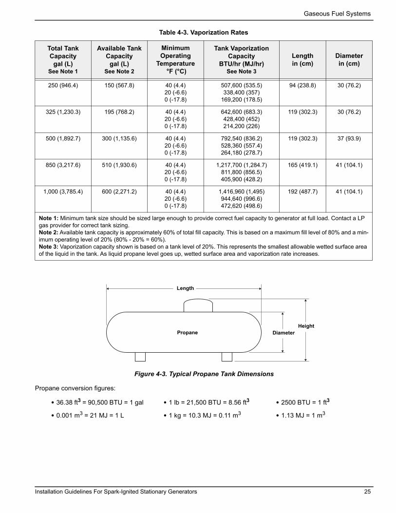
Gaseous Fuel Systems
Propane
Length
DiameterHeight
Figure 4-3. Typical Propane Tank Dimensions
Table 4-3. Vaporization Rates
Total Tank Capacity
gal (L)See Note 1
Available Tank Capacity
gal (L)See Note 2
Minimum Operating
Temperature °F (°C)
Tank Vaporization Capacity
BTU/hr (MJ/hr) See Note 3
Length in (cm)
Diameterin (cm)
250 (946.4) 150 (567.8) 40 (4.4)20 (-6.6)0 (-17.8)
507,600 (535.5)338,400 (357)
169,200 (178.5)
94 (238.8) 30 (76.2)
325 (1,230.3) 195 (768.2) 40 (4.4)20 (-6.6)0 (-17.8)
642,600 (683.3)428,400 (452)214,200 (226)
119 (302.3) 30 (76.2)
500 (1,892.7) 300 (1,135.6) 40 (4.4)20 (-6.6)0 (-17.8)
792,540 (836.2)528,360 (557.4)264,180 (278.7)
119 (302.3) 37 (93.9)
850 (3,217.6) 510 (1,930.6) 40 (4.4)20 (-6.6)0 (-17.8)
1,217,700 (1,284.7)811,800 (856.5)405,900 (428.2)
165 (419.1) 41 (104.1)
1,000 (3,785.4) 600 (2,271.2) 40 (4.4)20 (-6.6)0 (-17.8)
1,416,960 (1,495)944,640 (996.6)472,620 (498.6)
192 (487.7) 41 (104.1)
Note 1: Minimum tank size should be sized large enough to provide correct fuel capacity to generator at full load. Contact a LP gas provider for correct tank sizing.Note 2: Available tank capacity is approximately 60% of total fill capacity. This is based on a maximum fill level of 80% and a min-imum operating level of 20% (80% - 20% = 60%).Note 3: Vaporization capacity shown is based on a tank level of 20%. This represents the smallest allowable wetted surface area of the liquid in the tank. As liquid propane level goes up, wetted surface area and vaporization rate increases.
Propane conversion figures:
• 36.38 ft3 = 90,500 BTU = 1 gal • 1 lb = 21,500 BTU = 8.56 ft3 • 2500 BTU = 1 ft3
• 0.001 m3 = 21 MJ = 1 L • 1 kg = 10.3 MJ = 0.11 m3 • 1.13 MJ = 1 m3
Installation Guidelines For Spark-Ignited Stationary Generators 25

Gaseous Fuel Systems
Final Operating TestA correctly configured and sized fuel system provides the fuel volume and fuel pressure required for the generator set to operate correctly in all modes of operation. To ver-ify correct fuel system operation, a series of tests must be performed as described below.
Fuel Shutoff ValveMost applications will require an external manual fuel shutoff valve on the fuel line. The fuel shutoff valve must be readily accessible. Local codes determine correct location.
Figure 4-4. Fuel Shutoff Valve with Manometer Port
NOTE: Figure 4-4 illustrates a fuel shutoff valve with a manometer port for making fuel pressure checks. This accessory fuel shutoff valve permits making pressure checks without going into the generator enclosure.
Valves available through Generac and IASD’s:• 3/4 in pressure rated ball valve, part number 0K8754• 1 in pressure rated ball valve; part number 0K8184• 1-1/4 in pressure rated ball valve; part number
0L2844• 1-1/2 in ball valve; part number 0L2856• 2 in ball valve; part number 0L2846
Fuel Pressure Test Port LocationUsing a suitable pressure gauge or water manometer, measure fuel pressure to the generator at a test port located before the fuel solenoid shutoff valve(s).See A of Figure 4-5. On units using demand type fuel regulator(s), there may be a factory-installed 1/8 in pipe port in a tee fitting connected to the low pressure switch. See B of Figure 4-5. If unit has a low pressure switch without the tee, install a tee and plug it between the low pressure switch and the test port on the fuel regulator body using a suitable pipe dope. Use only the upper port on fuel regulator body, as it detects supply fuel pressure even when the unit solenoid valve is closed. This allows static fuel pressure to be measured, as well as fuel pres-
sure when cranking, while running at no load, and while running at full load.See C of Figure 4-5. Factory installed at the test point, some units may be provided with a special test port plug known as a “Pete’s Plug®.” The plug allows fuel pressure test readings to be taken quickly without leaving costly gauges installed in the fuel line. Use the “Pete’s Plug” as follows:
1. Clean and lubricate gauge adapter probe with a small amount of petroleum jelly or silicone grease.
2. Assemble gauge adapter.3. Screw barbed fitting into gauge adapter using the
appropriate sealant.4. Install fuel line of correct pressure gauge onto
barbed fitting.5. Slowly unscrew protective cap from test port plug.
NOTE: Quickly tighten cap if escaping gas or liquid is heard or felt. Replace plug if faulty.
6. Insert gauge adapter into test port plug and secure.7. Remove gauge adapter probe and screw protec-
tive cap onto fuel pressure test port plug once fuel pressure reading is obtained.
NOTE: Take necessary readings as quickly as possible. Severe deformation of valves may occur if gauge adapter probe is left in test port plug for a period of hours or days.
NOTE: Below 45 °F (7 °C), the neoprene core of the plug does not recover its original shape as rapidly as it would at higher temperatures. Upon removal of gauge adapter probe, valves may not close fully and immediately, or they may remain slightly open until operating tempera-ture is above 45 °F (7 °C). Lower pressures and the length of time gauge adapter probe is inserted can also affect valve closing rate. The protective cap is provided to eliminate the small amount of leakage that might occur following removal of the gauge adapter probe.
8. Tighten protective cap to prevent tampering.
000743
26 Installation Guidelines For Spark-Ignited Stationary Generators
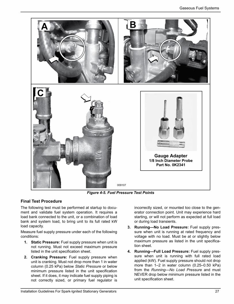
Gaseous Fuel Systems
Figure 4-5. Fuel Pressure Test Points
Final Test ProcedureThe following test must be performed at startup to docu-ment and validate fuel system operation. It requires a load bank connected to the unit, or a combination of load bank and system load, to bring unit to its full rated kW load capacity. Measure fuel supply pressure under each of the following conditions:
1. Static Pressure: Fuel supply pressure when unit is not running. Must not exceed maximum pressure listed in the unit specification sheet.
2. Cranking Pressure: Fuel supply pressure when unit is cranking. Must not drop more than 1 in water column (0.25 kPa) below Static Pressure or belowminimum pressure listed in the unit specification sheet. If it does, it may indicate fuel supply piping is not correctly sized, or primary fuel regulator is
incorrectly sized, or mounted too close to the gen-erator connection point. Unit may experience hard starting, or will not perform as expected at full load or during load transients.
3. Running—No Load Pressure: Fuel supply pres-sure when unit is running at rated frequency and voltage with no load. Must be at or slightly below maximum pressure as listed in the unit specifica-tion sheet.
4. Running—Full Load Pressure: Fuel supply pres-sure when unit is running with full rated load applied (kW). Fuel supply pressure should not drop more than 1–2 in water column (0.25–0.50 kPa) from the Running—No Load Pressure and must NEVER drop below minimum pressure listed in the unit specification sheet.
A B
C
Gauge Adapter1/8 Inch Diameter Probe
Part No. 0K2341
009107
Installation Guidelines For Spark-Ignited Stationary Generators 27

Gaseous Fuel Systems
This page intentionally left blank.
28 Installation Guidelines For Spark-Ignited Stationary Generators

Electrical System
Section 5: Electrical SystemGeneral InformationAll wiring must be correctly sized, routed, supported, and connected. All wiring must comply with NEC and local codes.The generator uses Customer Connection Interface (CCI) panels to separate high voltage and customer con-trol wiring connections. These two panels are clearly labeled. Wiring diagrams for each specific unit show con-nection points in their corresponding sections. Terminal boards are labeled and correspond to the same terminal connections shown in the wiring diagrams. Always useunit specific wiring diagrams when making wiring connec-tions.
NOTE: See Alternator AC Lead Connections.
Connecting Generator Feeder Conductors
NOTE: Installation and interconnection diagrams are provided at the back of this manual.
NOTE: All installations must comply with national, state, and local codes. It is the responsibility of the installer to perform an installation that will pass final electrical inspection.
Generator supply connection is made at the generator disconnect circuit breaker terminals. Conductor sizes must be adequate to handle the maximum current to which they will be subjected, based on the 75 °C column of tables, charts, etc., used to size conductors. Installa-tion must comply fully with all applicable codes, stan-dards, and regulations.All power cables can enter enclosure through knockouts provided.
NOTE: Apply corrosion inhibitor to conductors if alumi-num conductors are used. Carefully wipe away any excess corrosion inhibitor after tightening terminal lugs.
Tighten terminal lugs to torque values noted on decal located on the inside of the door. Carefully wipe away any excess corrosion inhibitor after tightening terminal lugs.Proceed as follows to connect generator conductors to marked terminal lugs in generator:
1. See Figure 5-1. Connect generator conductors to disconnect circuit breaker.
Figure 5-1. High Voltage Connections (Typical)
2. Connect generator neutral to neutral terminal bar.3. Connect equipment ground to equipment ground
lug.
Electrocution. Turn utility and emergencypower supplies to OFF before connecting power source and load lines. Failure to do so will result in death or serious injury. (000116)
DANGER
(000120)
CAUTIONEquipment damage. Verify all conductors aretightened to the factory specified torque value.Failure to do so could result in damage to the switch base.
Load Wiring Connections1 E1 4 Ground2 E2
5 Knock Out Plug (Cold Weather Kit)3 Neutral
Notes:Single-phase installation shown.See Figure 5-4 for typical control wiring connections.
001758
1 2
3
4
5
Installation Guidelines For Spark-Ignited Stationary Generators 29

Electrical System
Connecting Control Circuit WiresControl system interconnections may consist of N1, N2, and T1, and leads 23 and 194. The generator control wir-ing is a Class 1 signaling circuit. See instruction manual of specific engine generator for wiring connection details. Recommended wire gauge sizes for wiring depends on length of wire, as recommended in the following chart:
Exception: Conductors of AC and DC circuits, rated 1,000 volts nominal or less, shall be permitted to occupy the same equipment, cable, or conduit. All conductors shall have an insulation rating equal to at least the maxi-mum circuit voltage applied to any conductor within the equipment, cable, or conduit. See NEC 300.3(C)(1).
Removing Rear Panel and Stub-Up Cover
1. See Figure 5-2. Remove six screws with nylon washers to release rear panel (A) from enclosure. For best results, rotate left side of panel outward away from enclosure before disengaging right side.
Figure 5-2. Remove Rear Panel and Stub-Up Cover
2. Remove four screws with nylon washers to release fascia from control panel.
3. The stub-up cover (B) and five screws with flat washers are shipped loose and found inside the enclosure. An optional knock-out (C) is provided.
Table 5-1. Frame BreakersFrame Breaker
Generac 225 AF 2 Pole
Generac 225 AF 3 Pole
Generac 400 AF 2 Pole
Generac 400 AF 3 Pole
Range 125A-200A 50A-200A 225A-400A 225A-400A
Wire Type Cu/Al Cu/Al Cu/Al Cu/Al
Wire Temp. Rating
167 °F(75 °C)
167 °F(75 °C)
167 °F(75 °C)
167 °F(75 °C)
Lug AWG Range(Number of Conductors)
6-350 kcmil (1) 6-350 kcmil (1) 1/0 -250 kcmil (2) or
4-600 kcmil (1)
1/0-250 kcmil (2)or
4-600 kcmil (1)
NOTE: Generac frame breakers are rated at an 80% continuous load rating. Frame breaker torque specs are on the breaker data tag.
Typical Load Leads and Control Wiring in Stub-UpFigure 5-3 is for reference only. See installation drawings for unit-specific details.
NOTE: See 300.3(C) and Article 725 in the NEC for rout-ing of control wires and power wires.
NOTE: A single conduit is permitted.
Figure 5-3. Typical Load Leads and Control Wiring in Stub-Up
Customer Load WiringCustomer load wiring consists of single-phase or three-phase connections between generator main line circuit breaker (MLCB) and transfer switch. The wiring connects to lugs E1, E2, (and E3, if three-phase on MLCB), neu-tral, and equipment ground at generator, and runs to cor-responding lugs in transfer switch. All load wires, neutral,and ground should be marked and terminated in the cor-rect lugs in transfer switch. Verify all wiring is correctly mounted and terminated at appropriate connection points in both generator and transfer switch. For general infor-
Maximum Wire Length Recommended Wire Size1–115 ft (0.30–35 m) No. 18 AWG116–185 ft (36–56 m) No. 16 AWG186–295 ft (57–89 m) No. 14 AWG296–460 ft (90–140 m) No. 12 AWG
000384
A
B
C
A Load leads C Stub-ups
B Control wiring D Concrete pad
000385
A BD
C
30 Installation Guidelines For Spark-Ignited Stationary Generators

Electrical System
mation regarding wire type, temperature rating, size range, and wire lug torque specifications, see Table 5-1 and Table 5-2. Always see NEC tables for specific requirements.
NOTE: For three-phase applications, use phase rotation meter to verify generator phase rotation matches rotation of the utility.
NOTE: For three-phase, delta configured alternators (voltage code J) and the second leg (N2) must be bonded to all second legs in the entire system.
See Alternator AC Lead Connections for more infor-mation.
Control Wiring ConnectionsThe control wire customer connection block is where all of the control wiring is connected.
IMPORTANT NOTE: All wiring must comply with NEC, state, and local AHJ requirements. Control wir-ing shall be installed per the requirements of NEC Articles 300.3(C) and 725.46. If installing conductors with different voltage insulation ratings, a 600V rated electrical sleeve is provided and can be found in the manual bag.
See Figure 5-4. Depending on the system type, control wiring includes the following. (Wire colors shown for illus-tration purposes only):
RTS Series Transfer Switch With T1 Fuse/ConnectionNOTE: Control wire customer connections typically use Class 1 Wiring Methods (verify with AHJ). Always follow the standards and methods appropriate to the circuits being wired.
NOTE: T1 is the 120 VAC power supply for the control panel battery charger. This circuit must be powered whether transfer switch is in utility or generator mode. If circuit loses power, control board will generate a warning (Battery Charge AC Fail).
NOTE: Observe maximum wire size for terminal strip connections shown in the unit wiring diagram.
(1) For battery charging, connect neutral in TB2 to neutral in transfer switch. See NOTE below for transfer switches without T1.(2) Connect T1 in TB2 to T1 in transfer switch. This is 120 volt supply to the unit's battery charger (normal RTS transfer switch). (3) (4) Connect N1, N2 sensing wires in TB2 to N1 and N2 in transfer switch. These two wires are utility sensing wires. (5) (6) Connect 23 in TB3 to 23 in transfer switch. Con-nect 194 in TB3 to 194 in transfer switch. These are transfer switch control wires.
NOTE: RTS Series Transfer Switch Without T1 Fuse/Connection: Use a 120 volt generator protected circuit from the panel board to power the battery charger circuit (dedicated 15/20 amp circuit).
Figure 5-4. Control Wiring Connections (Typical)
TB2 Terminal Block
Terminal Function Voltages
1 Neutral Neutral for T1 Battery Charger Neutral
2 T1 Power for T1 Battery Charger 120 VAC
3 N2 Utility Sensing from Transfer Switch 208-277 VAC
4 N1 Utility Sensing from Transfer Switch 208-277 VAC
TB3 Terminal Block
Terminal Function Voltages
A 178 Two Wire Start Control [GTS] 5 VDC
B 183 Two Wire Start Control [GTS] 5 VDC
5 23 Transfer Relay Control Wire 12-0 VDC
6 194 Power for Transfer Relay 12 VDC
009122
1
2
3
4
A
B
5
6
Installation Guidelines For Spark-Ignited Stationary Generators 31

Electrical System
Two-Wire StartTo convert control panel to two-wire start transfer switch mode of operation, see dealer for panel conversion and connection of terminals 178 and 183 in TB3. Use a 120 volt generator protected circuit from the panel board to power the battery charger circuit (dedicated 15/20 amp circuit).The generator controller will have to be programmed for two-wire start by an IASD.
NOTE: FOR FIELD WIRING TO CUSTOMER CONNECTIONS (TERMINAL BLOCKS) WIRE SIZE 18-12 GAUGE
COMPONENTS LOCATED IN CUSTOMER CONNECTION BOXLOW VOLTAGE CONNECTIONS
COMPONENTS LOCATED IN CUSTOMER CONNECTION BOXHIGH VOLTAGE CONNECTIONS
NOTE: ALL WIRES ON THIS PAGE ARE 600V RATED
TRANSFER RELAY
TRANSFER RELAY COIL
CU
STO
MER
CO
NN
ECTI
ON
S
2 23
E-STOP
178
183
4
3
1941
178
23
183
194
J1-14
J1-7
J1-5
J1-6
CU
STO
MER
CO
NN
ECTI
ON
S
ES
COMMON ALARM209/210J1-8
CAR
J1-15
FUSED 120VACSOURCE FORBATTERY CHARGER
UTILITY FROMTRANSFER SWITCH
000378
UTILITY FROMTRANSFER SWITCH
3 T1
NEU4NEU
N2
N1
N2 2
T1
1N1
3 N1
N24
N2
N1
2
1
60HZ UNITS 50HZ (M-VOLTAGE, 110/220VAC & R-VOLTAGE, 231/400VAC)
BCH2-2
J4-6
BCH2-1
J4-3
FUSED 220VAC(M) OR 200VAC(R) SOURCE FOR BATTERY CHARGER(PRE-CONNECTED WITH JUMPERS AS SHOWN)
YTB3X
60HZ/50HZ
REMOTE START OPTION
X TB2 Y
NEU
N2
T1
N1
BCH2-2
J4-6
BCH2-1
J4-3
X TB2 Y
240VAC MAX
(BLACK)
(WHITE)
J2-8COP1-7
J1-3
J2-4
SPLICE E(ORANGE)J1-9
395/396
56/56A
14/14A
Figure 5-5. Typical Control Wiring Schematic
32 Installation Guidelines For Spark-Ignited Stationary Generators

Electrical System
NOTE: The following table is provided for reference pur-poses only. See latest NEC, state, and local AHJ require-ments for correct sizing.
Optional Accessory Power• Accessory power for optional items (battery
warmer and block heater) should come from a cus-tomer utility supply source (with appropriate sized breaker), which is also powered by emergency power during an outage.
• Optional user installed GFCI receptacles. Provides a place to plug in optional battery warmer and block heater.
NOTE: See Figure 5-2. Remove knockout plug and route accessory wiring to customer supplied weather-proof junction box. Verify wires do not contact moving or vibrating engine parts, as abraded wires can result in electrical problems.
Installing Stub-Up Cover and Rear Panel
1. Install five screws with flat washers to secure stub-up cover.
2. Install four screws with nylon washers to fasten fascia over control panel.
3. Install rear panel. For best results, first engage right side of panel and then rotate left side inward toward enclosure. Alternately work left and right sides in until slots are aligned with screw holes on both sides. Install six screws with nylon washers and tighten until snug.
Transfer Switch LocationThe location of the transfer switch is important. Consider the following:
• Locate transfer switch as close to emergency load as practical, to avoid interruptions of emergency power system due to natural disasters or equip-ment failures.
• Locate transfer switch in a clean, dry, well venti-lated location, away from excessive heat. Allow adequate working space around transfer switch.
See latest NEC, state, and local AHJ requirements for details.
• Install power and control wires as per NEC require-ments. In a three-phase system, all power conduits from the generator must contain all three phases.
• Conduit, wire, circuit protective device sizes, insu-lation, etc. must conform to applicable local and national codes and regulations.
BatteryGeneral Safety Precautions
Table 5-2. Control Wire Length/Size
Maximum Wire Length
Recommended Wire Size
1–115 ft (0.30–35 m) No. 18 AWG
116–185 ft (36–56 m) No. 16 AWG
186–295 ft (57–89 m) No. 14 AWG
296–460 ft (90–140 m) No. 12 AWG
Automatic start-up. Disconnect utility power and render unit inoperable before working on unit. Failure to do so will result in death or serious injury.
(000191)
DANGER
(000188)
DANGERElectrocution. Do not wear jewelry while working on this equipment. Doing so will result in death or serious injury.
(000130)
WARNINGAccidental Start-up. Disconnect the negative battery cable, then the positive battery cable when working on unit. Failure to do so could result in death or serious injury.
(000137a)
WARNINGExplosion. Batteries emit explosive gases while charging. Keep fire and spark away. Wear protective gear when working with batteries. Failure to do so could result in death or serious injury.
(000138a)
WARNINGRisk of burns. Batteries contain sulfuric acid and can cause severe chemical burns. Wear protective gear when working with batteries. Failure to do so could result in death or serious injury.
(000133)
WARNINGExplosion. Batteries emit explosive gases. Always connect positive battery cable first to avoid spark. Failure to do so could result in death or serious injury.
Installation Guidelines For Spark-Ignited Stationary Generators 33

Electrical System
Always recycle batteries in accordance with local laws and regulations. Contact your local solid waste collection site or recycling facility to obtain information on local recycling processes. For more information on battery recycling, visit the Battery Council International website at: http://batterycouncil.org
• Stationary generators installed with automatic transfer switches will crank and start automatically when NORMAL, UTILITY source voltage is removed or is below an acceptable preset level. To prevent automatic startup and possible injury to personnel, do not connect battery cables until NORMAL source voltage at transfer switch is cor-rect and system is ready to be placed into opera-tion.
• When working on battery, only use tools with insu-lated handles. Do not rest tools or metal parts on top of battery.
• Discharge static electricity from the body before touching battery by first touching a grounded metal surface.
• Immediately wash down spilled electrolyte with an acid neutralizing agent. Use a solution of 1 lb (500 g) bicarbonate of soda to 1 gal (4 L) of water. Add the bicarbonate of soda solution until evidence of reaction (foaming) has ceased. Flush resulting liq-uid with water.
Battery RequirementsThe ability to start the engine depends upon battery capacity, ambient temperatures, and coolant and oil tem-peratures. The engine/generator set data sheet lists mini-mum recommended battery capacity at various ambient temperatures. Recommended battery capacities are listed under cold cranking amps (CCA) at 0 °F (−18 °C). Battery capacities decrease as ambient temperatures decrease, so it is important to specify batteries with the appropriate CCA rating at a temperature no higher than the minimum ambient temperature for the application.
Battery InstallationFill battery with correct electrolyte fluid as necessary and have battery fully charged before installing it.Use appropriate tools when working with battery termi-nals. The use of terminal pullers, expansion pliers, and terminal cleaning brushes will greatly extend the life of the battery terminals.
1. See Figure 5-6. Install rubber protective cover (A) over positive (+) battery terminal.
2. Grasp battery strap (B) and lift battery.3. Set battery onto battery tray. 4. Tighten two screws with nylon washers to secure
hold-down clamp to battery tray.5. Remove rubber protective cover from positive (+)
battery terminal.6. Install positive battery cable (C) (red) on positive
(+) battery terminal.7. Install negative battery cable (D) (black) on nega-
tive (-) battery terminal.
NOTE: The unit is equipped with a internal battery char-ger. The internal battery charger is powered by the T1 wire. Verify power supply (T1 wire) has been safely dis-connected before performing any work on the battery.
Figure 5-6. Battery Cable Connections
NOTE: At temperatures of 32 °F (0 °C) and below, it is recommended that a pad type battery heater be installed to aid in cold climate starting. This is available as a cold weather kit through an IASD.
WARNING
(000228)
Environmental Hazard. Always recycle batteries at an official recycling center in accordance with all local laws and regulations. Failure to do so could result in environmental damage, death, or serious injury.
001499
A
B
-+
000621
C
D
34 Installation Guidelines For Spark-Ignited Stationary Generators

Control Panel Startup / Testing
Section 6: Control Panel Startup / TestingControl Panel InterfaceThe control panel interface is located behind the door on the alternator end of the enclosure.
Using the AUTO/MANUAL/OFF Buttons
Button Description of Operation
Auto
Activates fully automatic system operation. Auto-matic operation allows unit to automatically start and exercise generator according to exercise timer settings (see Setting The Exercise Timer).
Off Shuts down engine and also prevents automatic operation and exercise of unit.
Manual Cranks and starts generator. Transfer to standby power will not occur unless there is a utility failure.
Figure 6-1. Generator Control Panel
Generator SetupController will light up when battery power is applied to generator during the installation process. Generator still needs to be activated before it will automatically run in event of a power outage. See Activate Unit.
Setting The Exercise Timer This generator is equipped with a configurable exercise timer. There are two settings for the exercise timer.
• Day/Time: Once set, generator will start and exer-cise for period defined, on day of week and at time of day specified. During this exercise period, unit runs for approximately 5 or 12 minutes, depending on model, (see Table 6-1) and then shuts down.
• Exercise frequency (how often exercise will take place): It can be set to Weekly, Biweekly, or Monthly. If MONTHLY is selected, day of month must be selected from 1–28. Generator will exer-cise on selected day each month. Transfer of loads to generator output does not occur during exercise cycle unless utility power is lost.
NOTE: If installer tests generator prior to installation, press ENTER button to skip setting up exercise timer.
NOTE: Exercise feature will operate only when genera-tor is placed in AUTO, and will not work unless this pro-cedure is performed. Current date/time will need to be reset every time the 12 volt battery is disconnected and then reconnected, and/or when the fuse is removed.
000425
Table 6-1. Exercise Parameters
Generator Size 22 kW 25 kW 27 kW 30 kW 32 kW 36 kW 38 kw 45 kW 48 kW 60 kW
Quiet Test Speed (rpm) 1,400 1,800 1,400 1,800 1,500 1,800 1,500 1,800 1,400 1,800
Exercise Speed 1,800 or 3,600 rpm
Exercise Frequency Options Weekly, Bi-weekly, Monthly
Exercise Duration 12 minutes
Installation Guidelines For Spark-Ignited Stationary Generators 35

Control Panel Startup / Testing
Before Initial Startup
NOTE: This unit has been run and tested at the factory prior to being shipped and does not require any type of break-in.
NOTE: This unit comes factory-filled with 30 weight organic oil. Verify oil level and add the appropriate vis-cosity and amount of oil if necessary.
Install WizardSee Figure 6-2. Upon initial startup, Install Wizard imme-diately appears. It allows user to input generator settings.The Install Wizard starts every time AC and DC power are removed and reapplied to generator.
Interconnect System Self Test FeatureThis controller goes through a system self test at startup, which checks for utility (AC) voltage on DC circuits. This check prevents damage if installer incorrectly connects AC utility power sense wires into DC terminal block. Con-troller will display a warning message and lock out the generator if utility voltage is detected, preventing damage to controller. Power to controller must be removed to clear this warning.Utility voltage must be turned on and present at the N1 and N2 terminals inside generator control panel for this test to be performed and pass.
NOTE: All appropriate panels must be in place during any operation of the generator. This includes operation by a servicing technician, while conducting troubleshoot-ing procedures.
Before starting, complete the following:1. Verify generator is OFF.2. Set generator MLCB to OFF (OPEN).3. Turn off all breakers powered by generator.4. Check engine crankcase oil level and, if necessary,
fill to oil dipstick FULL mark with recommended oil. Do not fill above FULL mark.
5. Inspect fuel supply. Gaseous fuel lines must have been correctly purged and leak tested in accor-dance with applicable fuel-gas codes. All fuel shut-off valves in the fuel supply lines must be open.
6. Verify both auxiliary shutdown switches are ON (I).During initial startup only, generator may exceed normal number of start attempts and experience an “OVER-CRANK” fault. This is due to accumulated air in the fuel
system during installation. Reset control board by press-ing OFF button and ENTER button, and restart up to two more times if necessary. If unit fails to start, contact an IASD for assistance.
Checking Manual Transfer Switch Operation
See Manual Transfer Operation section of owner’s man-ual for procedures.
(000135)
Engine damage. Verify proper type and quantity of engine oil prior to starting engine. Failure to do so could result in engine damage.
CAUTION
(000129)
DANGERElectrocution. High voltage is present at transfer switch and terminals. Contact with live terminals will result in death or serious injury.
36 Installation Guidelines For Spark-Ignited Stationary Generators

Control Panel Startup / Testing
Figure 6-2. Install Wizard Menu Map
UP
AR
RO
W =
+
DO
WN
AR
RO
W =
-
SYST
EM
BAT
-
DAT
E/TI
ME
SUB
MEN
US
Lang
uage
+ E
nglis
h -
+ E
span
ol -
+ F
ranc
ais
-+
Por
tugu
ese
-
Inst
all W
izar
d
Set E
xerc
ise
Inst
all W
izar
d
Pow
er U
p U
nit
Sele
ct H
our (
0-23
)
- 14
+
Sele
ct M
in (0
-59)
- 0
+
ENTE
REN
TER
ENTE
R
ENTE
R
ENTE
R
Sele
ct H
our (
0-23
)
- 14
+
Sele
ct M
in (0
-59)
- 0
+
ENTE
R
ENTE
R
Sele
ct M
onth
(1-1
2)
- 2
+
ENTE
RSe
lect
Dat
e (1
-31)
- 13
+
ENTE
RSe
lect
Yea
r (0-
99)
- 13
+
ENTE
R
FIR
MW
ARE
V 1
.01
HAR
DW
ARE
V 1
.05
* H
oldi
ng th
e U
p or
Dow
n ar
row
bu
tton
for 2
sec
onds
will
spee
d di
al
thro
ugh
the
sele
ctio
ns
Def
aults
to E
nglis
h if
not s
elec
ted.
Not
e: If
lang
uage
was
pre
viou
sly
prog
ram
med
this
goe
s di
rect
ly to
“Sel
ect H
our”
Use
UP
and
DO
WN
ar
row
s to
sel
ect f
uel
type
then
pre
ss
“EN
TER
”
**
**
*
***
Switc
hed
to “O
FF”
Hou
rs o
f Pro
tect
ion
0 (H
)
Sele
ct D
ay
- W
edne
sday
+
Sele
ct F
requ
ency
- W
EEKL
Y +
- BI
WEE
KLY
+-
MO
NTH
LY +
0036
54
Prod
uct R
egis
tratio
n(if
not
alre
ady
reg
iste
red)
Qui
et T
est M
ode
+
y
es
-
+
no
-
ENTE
R
G
UI F
W V
1.0
1
SEE
PRO
M V
1.0
1
Installation Guidelines For Spark-Ignited Stationary Generators 37

Control Panel Startup / Testing
Activate Unit
Display Reads: Generator Active is displayed on the LCD screen when the unit is first powered up. After displaying firmware and hardware version codes, as well as other system information, the Install Wizard is launched, and the Language screen is displayed.
Use UP ARROW or DOWN ARROW to scroll to desired language.
Press ENTER.
If the wrong language is selected, it may be changed later using the Edit menu.
Display Reads: Press ENTER. Press ESCAPE to abort the activation sequence. NOT ACTIVATED is displayed and the generator will run in manual mode only. Disconnect and reconnect the negative battery cable to restart the activation routine. If power is removed after a successful activation, no data is lost, but the time and date must be updated.
Display Reads: Go to www.activategen.com or call 1-888-9ACTIVATE (922-8482, US & Canada only) if activation passcode is not available.
If activation passcode is available, wait a few seconds for the next display.
Display Reads: Use UP ARROW or DOWN ARROW to increment or decrement the digit to correspond to the first number of the passcode.
Press ENTER.
Repeat step to enter remaining digits.
Press ESCAPE to return to preceding digits if a correction becomes necessary.
If attempts to enter the activation code are unsuccessful, check the number against the passcode given on activategen.com. If it is correct, contact 1-888-9ACTIVATE (922-8482, US & Canada only).
Language- English +
Up Arrow = (+)
Down Arrow = (-)
Activate me (ENT) orESC to run in manual
To Activate go towww.activategen.com
SN 1234567890PASS CODE XXXXX
38 Installation Guidelines For Spark-Ignited Stationary Generators

Control Panel Startup / Testing
Operational ChecksNOTE: The following procedures require special tools and skills. Contact a Generac dealer or an IASD to per-form these tasks.
Electrical Checks
NOTE: Verify all power and control wiring is correctly ter-minated in the generator and corresponding location in transfer switch. For three-phase applications, verify gen-erator phase rotation matches utility phase rotation L1-L2-L3 or L3-L2-L1. Validate phase rotation L1-L2-L3 or L3-L2-L1 with an phase rotation tester (if three-phase).
NOTE: To correct phase rotation, interchange any two leads.
Proceed as follows to complete electrical checks:1. Verify generator is in OFF mode. Red LED above
OFF on control panel illuminates to verify system isOFF.
2. Verify MLCB on generator control panel is in OFF (OPEN).
3. Turn off all circuit breakers/electrical loads to be powered by generator.
4. Turn on utility power supply to transfer switch using the means provided (such as a utility main line cir-cuit breaker).
5. Use an accurate AC voltmeter to verify utility power source voltage across transfer switch terminals N1and N2 (and N3 if three-phase). Normal line-to-line voltage should be equivalent to rated unit voltage. Validate (if three-phase) phase rotation L1-L2-L3 or L3-L2-L1 with a phase rotation tester.
6. Verify utility power source voltage across terminals N1 and N2 (and N3 if three-phase) and transfer switch neutral lug.
7. Turn off utility power supply to transfer switch when utility supply voltage is compatible with transfer switch and load circuit ratings.
8. Verify both auxiliary shutdown switches are ON (I).9. Press MANUAL on control panel keypad to crank
and start engine.10. Allow engine to warm up for approximately five
minutes. Set MLCB on generator control panel toON (CLOSED).
11. Connect an accurate AC voltmeter and a fre-quency meter across transfer switch terminal lugs E1 and E2 (and E3 if three-phase).
12. Successively connect the AC voltmeter test leads across terminal lugs E1, E2, (and E3 if three-phase) and neutral. Voltage reading in each case should match utility voltage reading. If system is three-phase, verify generator phase rotation matches utility phase rotation.
13. Set MLCB on generator control panel to OFF (OPEN).
14. Press OFF on control panel to shut engine down.
IMPORTANT NOTE: Do not proceed unless generator AC voltage and frequency are correct and within stated limits.
Testing Generator Under Load
Proceed as follows to test generator with electrical loads applied:
1. Verify generator is in OFF mode. Red LED above OFF on control panel illuminates to verify system is OFF.
2. Turn off all breakers/electrical loads to be powered by generator.
3. Turn off utility power supply to transfer switch, using the means provided (such as a utility main line circuit breaker).
4. Manually set transfer switch to STANDBY, i.e., load terminals connected to generator’s E1 and E2 (and E3 if three-phase) terminals. Transfer switch oper-ating lever should be down in standby position.
5. Verify both auxiliary shutdown switches are ON (I).6. Press MANUAL on control panel. Engine should
crank and start immediately.7. Allow engine to warm up for approximately five
minutes.8. Set MLCB on generator control panel to ON
(CLOSED).9. Turn on circuit breaker/electrical loads to be pow-
ered by generator. Loads are now powered by standby generator.
10. Connect a calibrated AC voltmeter and a frequency meter across terminal lugs E1 and E2 (and E3 if three-phase). Voltage should be approximately unit rated voltage.
11. Allow generator to run at full rated load for 20–30 minutes. Listen for unusual noises, vibration, or other indications of abnormal operation. Inspect for oil leaks, evidence of overheating, etc.
(000129)
DANGERElectrocution. High voltage is present at transfer switch and terminals. Contact with live terminals will result in death or serious injury.
(000132)
DANGERElectrocution. Do not manually transfer under load. Disconnect transfer switch from all power sources prior to manual transfer. Failure to do so will result in death or serious injury, and equipment damage.
Installation Guidelines For Spark-Ignited Stationary Generators 39

Control Panel Startup / Testing
12. Turn off electrical loads when utility supply voltage is compatible with transfer switch and load circuit ratings.
13. Set MLCB on generator control panel to OFF (OPEN).
14. Allow engine to run at no-load for 2–5 minutes.15. Press OFF on control panel to shut engine down.
Testing Auxiliary Shutdown Switch Operation
Test auxiliary shutdown switches to verify correct opera-tion.
1. Verify auxiliary shutdown switches (A, B) are ON (I).
Figure 6-3. Auxiliary Shutdown Switch Locations
2. Press MANUAL on control panel to start engine.3. With engine running, set one auxiliary shutdown
switch to OFF (O). Engine will shut down immedi-ately.
• If engine stops, set auxiliary shutdown switch to ON (I), clear alarm on controller, and restart engine to verify generator is operating normally. After veri-fying normal operation of first auxiliary shutdown switch, verify operation of second auxiliary shut-down switch.
• If engine does not stop, auxiliary shutdown switch is not functioning correctly. Stop generator through control panel, and inspect wiring installation. Con-tact Generac Technical Support if problem cannot be identified or if assistance is needed.
Auxiliary shutdown switches are not intended to be a pri-mary means to shut down generator under normal oper-ating conditions. Accidental activation of an auxiliary shutdown switch will prevent generator from operating during a power outage.
Checking Automatic OperationProceed as follows to check system for correct automatic operation:
1. Verify generator is in OFF mode. Red LED above OFF on control panel illuminates to verify system is OFF.
2. Install front cover over transfer switch.3. Turn on utility power supply to transfer switch,
using the means provided (such as a utility main line circuit breaker).
NOTE: Transfer switch will transfer to utility position.
4. Set MLCB on generator control panel to ON (CLOSED).
5. Verify both auxiliary shutdown switches are ON (I).6. Press AUTO on control panel. System is now
ready for automatic operation.7. Turn off utility power supply to transfer switch.
With generator ready for automatic operation, engine will crank and start when utility source power is turned OFF after a 10 second delay (factory default setting). After starting, transfer switch connects load circuits to standby side. Allow system to operate through entire automatic sequence of operation.With generator running and loads powered by generator AC output, turn ON utility power supply to transfer switch. System transfers to UTILITY, and then runs through the cool down cycle and shuts down.
Installation Summary1. Verify installation has been performed correctly as
outlined by the manufacturer and that it meets all applicable laws and codes.
2. Test and verify correct operation of the system as outlined in the appropriate installation and owner’s manuals.
3. Educate end-user on correct operation, mainte-nance, and service call procedures.
(000399)
Equipment Damage. The auxiliary shutdown switch is not to be used to power down the unit under normal operating circumstances. Doing so will result in equipment damage.
CAUTION
004900
ON
OFF
ENGINESHUTDOWN
A
B
40 Installation Guidelines For Spark-Ignited Stationary Generators

Control Panel Startup / Testing
Shutting Generator Down While Under Load or During a Utility Outage
IMPORTANT NOTE: If user ever finds it necessary to turn generator OFF during prolonged utility outages to conserve fuel or perform maintenance, alert them to these important steps:
To turn generator OFF (while running in AUTO and online):
1. Turn main utility disconnect OFF (OPEN).2. Set MLCB on generator control panel to OFF
(OPEN). 3. Allow unit to run for a few minutes to cool, and then
press OFF on control panel. Red LED illuminates to verify system is OFF.
To turn generator back ON:1. Press AUTO on control panel. Allow unit to start
and warm up for a few minutes.2. Set MLCB on generator control panel to ON
(CLOSED). System is now operating in AUTO. The main utility dis-connect can be turned ON (CLOSED), but to shut unit down, this complete process must be repeated.
Automatic start-up. Disconnect utility power and render unit inoperable before working on unit. Failure to do so will result in death or serious injury.
(000191)
DANGER
Installation Guidelines For Spark-Ignited Stationary Generators 41

Control Panel Startup / Testing
This page intentionally left blank.
42 Installation Guidelines For Spark-Ignited Stationary Generators

Installation Checklists
Section 7: Installation ChecklistsSafety ChecklistNOTE: See Safety Rules & General Information for more information.
Are manuals, wiring diagrams, and other documenta-tion readily available?
Is there any evidence of freight damage?
Does the enclosure have scratches or damage to painted surfaces (which would indicate lifting without a spreader bar)?
Are all guards, covers, insulation blankets, and other protective devices in place?
Are any parts or components worn, damaged, or missing?
Is generator correctly grounded?
Is a fire extinguisher kept near generator?
Is there any evidence of oil or coolant leaks?
Are any combustible materials left in generator com-partment?
Is area surrounding generator clean and free of debris?
Do these parameters meet all applicable codes and local jurisdiction?
Installation Planning ChecklistNOTE: See Installation Planning for more information.
Is generator readily accessible for maintenance, repair, and firefighting purposes?
Is installation site clean, dry, and provided with ade-quate drainage?
Is there minimum clearance around the generator to facilitate repair or replacement of major components?
Have adequate provisions been made for installation of the fuel supply?
Do these parameters meet all applicable codes and local jurisdiction?
Foundations and Mounting ChecklistNOTE: See Site Selection and Preparation for more information.
Is generator installed on a concrete pad capable of supporting its weight and accessories?
Is generator securely fastened to concrete pad using suitable grade, size, and style fasteners?
Is concrete pad seated on a prepared solid subsur-face using appropriate reinforcing bar or expanded wire mesh?
Does concrete pad extend beyond the frame rails at least 3 in (7.62 cm) on all sides?
Is concrete pad flat and level to within 0.5 in (13 mm)?
Are plugs installed in the tie-down holes of frame rail?
If installed on a roof or combustible floor, is generator seated on a layer of sheet metal and non-combustible insulation? Do the sheet metal and insulation extend beyond generator base at least 12 in (300 mm) on all sides?
Is base frame stub-up cover plate installed?
Do all fuel, coolant, exhaust, and electrical lines have flexible sections where they connect to generator?
Is all piping correctly supported and secured?
Do these parameters meet all applicable codes and local jurisdiction?
Installation Guidelines For Spark-Ignited Stationary Generators 43

Installation Checklists
Ventilation System ChecklistNOTE: See Site Selection and Preparation for more information.
Is there sufficient air flow for cooling and ventilation?
Are all bushes, shrubs, and other vegetation a mini-mum of 3 ft (1 m) away?
Does the air inlet face the direction of prevailing winds?
Is system piping correctly sized? Have all gas loads been taken into consideration?
Is system correctly protected from freeze up and cor-rosion?
Have standby equipment heaters been specified?
Have system drain valves and air eliminators been installed?
Does air outlet face noise sensitive areas without noise attenuating devices?
Does installation appear to have the necessary acces-sories to promote fast, reliable starting and operation in adverse weather conditions (such as engine block heaters, battery warmers, etc.)?
Do these parameters meet all applicable codes and local jurisdiction?
Exhaust System ChecklistNOTE: See Gaseous Fuel Systems for more informa-tion.
Are exhaust discharges directed away from combusti-ble surfaces and inhabited areas?
Is exhaust piping kept clear of fuel supply, fuel lines, etc.?
Is off-engine exhaust piping covered with high tem-perature insulation blankets where necessary?
Do these parameters meet all applicable codes and local jurisdiction?
Gaseous Fuel System ChecklistNOTE: See Gaseous Fuel Systems for more informa-tion.
Are fuel supply lines correctly sized and installed? Were fuel supply lines purged and leak tested?
Are sediment traps installed to remove water and con-densate from the fuel flow?
Is fuel pressure regulator correctly sized?
Is a fuel pressure test port installed before fuel shutoff solenoids at inlet to the unit mounted fuel regulator?
Does generator have a dedicated fuel line which is not shared with any other appliances?
Is fuel regulator sized to have a fuel flow delivery rat-ing (CFH) at least 10% greater than the 100% rated kW fuel consumption requirement of the generator?
Is fuel pressure regulator approved for a mechanized engine application?
Does fuel pressure regulator have an accuracy rating of 1% or less, and/or have a maximum allowable fuel pressure drop of 1–2 in water column (0.25–0.50 kPa) under all operating conditions; that is, static, cranking, running at no load, and running at full load (as mea-sured at the primary fuel pressure regulator)?
Does fuel pressure regulator have a spring rating appropriate for the required fuel pressure as listed in the unit specification sheet?
Does fuel system use black iron piping or other approved fuel line?
Is fuel line rigidly mounted and protected against vibration?
Is a length of flexible fuel line installed between gener-ator connection point and rigid fuel supply piping? Is the flexible fuel line straight without bends, twists, or kinks?
Is fuel piping correctly sized to maintain required fuel supply pressure and volume under varying load con-ditions?
Was an approved pipe sealant or joint compound used on all threaded fittings?
Is a fuel shutoff valve installed near unit? Was correct operation of fuel shutoff valve verified?
Was Final Operating Test performed to verify system operates correctly in all modes of operation?
Is there any evidence of leakage at any hoses, clamps, or fittings?
Do these parameters meet all applicable codes and local jurisdiction?
44 Installation Guidelines For Spark-Ignited Stationary Generators

Installation Checklists
Electrical System Checklist NOTE: See Electrical System for more information.
Is all wiring correctly sized for load and length of run?
Is all wiring correctly routed?
Is all wiring correctly connected?
Are wire lugs fastened to bus bars using appropriate hardware? Is hardware correctly tightened to speci-fied torque?
Are all other terminals correctly tightened using the specified torque?
Are batteries correctly sized?
Are batteries correctly installed?
Are battery fluid levels correct?
Are battery cables and connections clean and free of corrosion?
Are battery cables correctly connected? Are terminal lugs correctly tightened?
Is battery condition and state of charge acceptable?
Is area housing storage battery correctly ventilated?
Are batteries located near a source of flame or spark?
Are AC wire sizes and connections correct?
Are DC and communication wire sizes and connec-tions correct?
Are block heaters, battery charger, etc. correctly matched with utility supply voltage?
Are battery charger and block heater correctly con-nected?
Are remote start Wires 178 & 183 pulled and con-nected inside lower control panel of generator and inside transfer switch?
Is generator set to OFF?
Is block heater operational?
Is battery charger operational?
Are all AC electrical connections tight at the circuit breaker and transfer switch?
Are two auxiliary shutdown switches ON (I)?
Are all electrical connections (wiring, wire ties, clamps, terminal ends, connectors) on generator tight?
Are all electrical plugs throughout generator seated correctly and fully inserted into their receptacles?
Is voltage and phase rotation correct at the transfer switch?
Is manual operation of transfer switch smooth and non-binding?
Do these parameters meet all applicable codes and local jurisdiction?
Oil Maintainer System Checklist (If Equipped)
NOTE: See Lube Oil Maintainer System for more infor-mation.
Has oil maintainer oil supply tank been filled with the recommended engine oil and tested?
Has oil maintainer been tested to correct level?
Installation Guidelines For Spark-Ignited Stationary Generators 45

Installation Checklists
This page intentionally left blank.
46 Installation Guidelines For Spark-Ignited Stationary Generators

Lube Oil Maintainer System
Section 8: Lube Oil Maintainer SystemLube Oil Maintainer SystemDescriptionThe 36 kW, 45 kW, and 60 kW models are equipped with a lube oil maintainer system. The lube oil maintainer system is factory-installed and factory-calibrated to the correct engine-running crankcase oil level. The lube oil maintainer system keeps engine lubricating oil full by automatically adding clean oil from oil supply tank as needed.
NOTE: Oil reservoir is empty when shipped from factory. Fill with clean engine oil to activate system.
Oil reservoir capacity: 2.5 gal (9.46 L)See Figure 8-1. The green bar (B) observed through the viewing lens (A) shows normal oil level operating range (C) of lube oil maintainer regulator during engine running operation. When oil level is within green bar, the internal float holds the inlet valve closed to keep crankcase oil at current level.
Figure 8-1. Lube Oil Maintainer Regulator
NOTE: Wires connected to viewing lens are not used in this application and can be disregarded.
As engine uses oil, float drops to open the inlet valve. Clean oil is drawn through the oil inlet screen (D) and into crankcase, replenishing engine oil to full mark indicated on oil dipstick. The float then rises with crankcase oil level until it reaches a point where inlet valve closes.When oil level as observed through the viewing lens is low (E) and below normal operating range green bar, it is an indication the oil supply tank is low or oil inlet screen is clogged.Test operation of the float and switch by pressing the test button (F).
NOTE: It is normal for oil level to be above normal operating range green bar when engine is not running.
NOTE: Close oil shutoff valve when changing engine oil to avoid draining clean oil in the oil supply tank with the crankcase oil. See Oil Shutoff Valve.
Fill Oil Supply Tank1. See Figure 8-2. Rotate plastic cover (G) counter-
clockwise and remove from top of enclosure.
Figure 8-2. Access Oil Supply Tank
2. Remove oil fill cap at top of oil supply tank.3. Add clean engine oil to oil supply tank (2.5 gal [9.5
L] capacity). 4. Install oil fill cap at top of oil supply tank.5. Install plastic cover at top of enclosure and rotate
clockwise until tight.
Test FunctionalitySee Figure 8-1. Momentarily press test button (F) to verify float is operating correctly.
IMPORTANT NOTE: Do not hold test button down for a prolonged period of time, or crankcase can be over filled. Overfilling crankcase can result in engine damage.
E C001757
F
D
A
B
009585
G
Installation Guidelines For Spark-Ignited Stationary Generators 47

Lube Oil Maintainer System
Oil Shutoff ValveSee Figure 8-3. Close oil shutoff valve when draining engine crankcase oil to avoid draining clean oil from supply tank.
Figure 8-3. Oil Shutoff Valve (Shown in Open Position)
Open oil shutoff valve after filling crankcase with clean oil to allow operation of lube oil maintainer system.
Figure 8-4. Lube Oil Maintainer Assembly and Function Diagram
009378
001756
E
F
G
H
A
B
C
D
J
K
O
N
M
L
F
B
A Oil inlet hose F Test button L RegulatorB Regulator viewing lens G Running engine crankcase M Oil shutoff valveC Center of green bar H Oil level N Oil supply tankD Crankcase hose J Engine crankcase oil pan O Oil fill capE Oil supply tank K Oil drain hose — —
48 Installation Guidelines For Spark-Ignited Stationary Generators

Troubleshooting/Quick Reference Guide
Section 9: Troubleshooting/Quick Reference GuideTroubleshooting
Problem Cause Correction
Engine will not crank
Blown fuse. Correct short circuit condition by replacing 7.5 amp fuse in generator control panel.
Loose, corroded, or faulty battery cables.Tighten, clean, or replace as necessary. Con-tact an IASD for assistance.Faulty starter contact.
Faulty starter motor.
Discharged battery. Charge or replace battery.
Engine cranks but will not start
No fuel. Verify fuel source / turn on fuel shutoff valve.
Faulty fuel solenoid (FS). Contact an IASD for assistance.
Faulty spark plug(s). Clean, re-gap, or replace plug(s).
Valve lash out of adjustment. Reset valve lash.
Engine starts hard and runs rough
Air cleaner plugged or damaged. Check / replace air cleaner.
Faulty spark plug(s). Clean, inspect gap, replace plug(s) if needed.
Incorrect fuel pressure. Verify fuel pressure to regulator is 5–14 in water column (1.24–3.48 kPa) for NG or 11–14 in water column (2.74–3.48 kPa) for LP gas.
Unit fuel regulator not converted for correct fuel source and/or not programmed for cor-rect fuel source.
Convert and program unit for correct fuel source.
Unit is set to OFF, but engine continues to run
Controller wired incorrectly.Contact an IASD for assistance.
Faulty control board.
No AC output from generatorMLCB is OFF (OPEN). Reset MLCB to ON (CLOSED).
Generator internal failure. Contact an IASD for assistance.
No transfer to standby after util-ity source failure
MLCB is OFF (OPEN). Reset MLCB to ON (CLOSED).
Faulty transfer switch coil.
Contact an IASD for assistance.Faulty transfer relay.
Transfer relay circuit open.
Faulty control logic board.
Unit consumes large amounts of oil
Excessive engine oil. Adjust oil to correct level.
Faulty engine breather. Contact an IASD for assistance.
Incorrect type or viscosity of oil. See Engine Oil Recommendations.
Damaged gasket, seal, or hose. Inspect for oil leaks.
Installation Guidelines For Spark-Ignited Stationary Generators 49

Troubleshooting/Quick Reference Guide
Quick Reference GuideTo clear an active alarm, press the ENTER button twice and then press AUTO. If the alarm reoccurs, contact an IASD.
Active Alarm LED Problem Things to Check Solution
NONE GREEN Unit running in AUTO but no power in house. Check MLCB. Check MLCB. If MLCB is ON, contact an
IASD for assistance.
HIGH TEMPERATURE RED Unit shuts down during
operation.Check LED’s / Screen
for alarms.
Inspect ventilation around generator, intake, exhaust, and rear of generator. If no obstruction, contact an IASD for assis-tance.
OVERLOAD REMOVE LOAD RED Unit shuts down during
operation.Check LED’s / Screen
for alarms.
Clear alarm and remove household loads from generator. Put back in AUTO and restart.
RPM SENSE LOSS REDUnit was running and
shuts down, attempts to restart.
Check LED’s / Screen for alarms.
Clear alarm and remove household loads from generator. Put back in AUTO and restart. If generator does not start, contact an IASD for assistance.
NOT ACTIVATED NONE Unit will not start in AUTO with utility loss.
Verify if screen says unit not activated. See Activate Unit.
NONE GREEN Unit will not start in AUTO with utility loss.
Check screen for start delay countdown.
If startup delay is greater than expected, contact an IASD for assistance.
LOW OIL PRESSURE RED Unit will not start in
AUTO with utility loss.Check LED’s / Screen
for alarms.Check oil level / add oil per owners man-ual. If oil level is correct, contact an IASD.
RPM SENSE LOSS RED Unit will not start in AUTO with utility loss.
Check LED’s / Screen for alarms.
Clear alarm. Check battery option in con-trol menu. If it states battery is GOOD, con-tact an IASD. If it states CHECK BATT-ERY, replace battery.
OVERCRANK RED Unit will not start in AUTO with utility loss.
Check LED’s / Screen for alarms.
Verify fuel line shutoff valve is ON. Clear alarm. Attempt to start unit in MANUAL. If it does not start or starts and runs rough, contact an IASD for assistance.
LOW VOLTS REMOVE LOAD RED Unit will not start in
AUTO with utility loss.Check LED’s / Screen
for alarms.
Clear alarm and remove household loads from generator. Put back in AUTO and restart.
FUSE PROBLEM RED Unit will not start in AUTO with utility loss.
Check LED’s / Screen for alarms.
Inspect 7.5 amp fuse. If it is bad, replace with an ATO 7.5 amp fuse. If fuse is good, contact an IASD for assistance.
OVERSPEED RED Unit will not start in AUTO with utility loss.
Check LED’s / Screen for alarms. Contact an IASD for assistance.
UNDERVOLTAGE RED Unit will not start in AUTO with utility loss.
Check LED’s / Screen for alarms. Contact an IASD for assistance.
UNDERSPEED RED Unit will not start in AUTO with utility loss.
Check LED’s / Screen for alarms. Contact an IASD for assistance.
STEPPER OVERCURRENT RED Unit will not start in
AUTO with utility loss.Check LED’s / Screen
for alarms. Contact an IASD for assistance.
WIRING ERROR RED Unit will not start in AUTO with utility loss.
Check LED’s / Screen for alarms. Contact an IASD for assistance.
OVERVOLTAGE RED Unit will not start in AUTO with utility loss.
Check LED’s / Screen for alarms. Contact an IASD for assistance.
50 Installation Guidelines For Spark-Ignited Stationary Generators

Troubleshooting/Quick Reference Guide
LOW BATTERY YELLOW Yellow LED illuminated in any state.
See screen for addi-tional information.
Clear alarm. Check battery option in con-trol menu. If it states battery is GOOD, con-tact an IASD. If it states CHECK BAT-TERY, replace battery.
BATTERY PROBLEM YELLOW Yellow LED illuminated in
any state.See screen for addi-
tional information. Contact an IASD for assistance.
CHARGER WARNING YELLOW Yellow LED illuminated in
any state.See screen for addi-
tional information. Contact an IASD for assistance.
SERVICE A YELLOW Yellow LED illuminated in any state.
See screen for addi-tional information.
Perform SERVICE A maintenance. Press ENTER to clear.
SERVICE B YELLOW Yellow LED illuminated in any state.
See screen for addi-tional information.
Perform SERVICE B maintenance. Press ENTER to clear.
INSPECT BATTERY YELLOW Yellow LED illuminated in any state.
See screen for addi-tional information. Inspect battery. Press ENTER to clear.
CHARGER MISSING AC YELLOW
AC input to battery char-ger circuit missing for
greater than 5 minutes during charging cycle.
Inspect connections at transfer switch, fuses
in transfer switch.Contact an IASD for assistance.
AUXILIARY SHUTDOWN RED
Unit either shuts down or does not start when one
or both switches are OFF (O).
See screen for addi-tional information.
Clear alarm and verify both auxiliary shut-down switches are ON (I). See Testing Auxiliary Shutdown Switch Operation for more information.
Active Alarm LED Problem Things to Check Solution
Installation Guidelines For Spark-Ignited Stationary Generators 51

Troubleshooting/Quick Reference Guide
This page intentionally left blank.
52 Installation Guidelines For Spark-Ignited Stationary Generators

Accessories
Section 10: AccessoriesPerformance enhancing accessories are available for liquid-cooled generators.
Item Description Part NumberCold Weather Kit
Recommended in areas where temperatures fall below 32 °F (0 °C).
G006175-0—25 & 30 kWG005630-1—36, 45, & 60 kW
Extreme Cold Weather Kit
Engine block heater. Used in conjunction with the appropriate Cold Weather Kit.NOTE: Engine oil must be replaced with synthetic oil.
G006174-0—25 & 30 kWG005616-0—36, 45, & 60 kW
Scheduled Maintenance Kit
Includes all pieces necessary to perform mainte-nance on the generator along with oil recommen-dations.
G006176-0—25 & 30 kWG006172-0—36 & 45 kWG006171-0—60 kW
Mobile Link™ (USA only)
Provides a personalized web portal that displays the generator status, maintenance schedule, event his-tory and much more.
G006463-4
Touch-Up Paint Kit
Very important to maintain the look and integrity of the generator enclosure. This kit includes touch-up paint and instructions.
G005703-0—BisqueG005704-0—Gray
Wireless Local Monitor
Completely wireless and battery powered, the Wireless Local Monitor provides you with instant status without ever leaving the house. Status lights (red, yellow, and green) alert owners when the generator needs attention. Magnetic backing per-mits refrigerator mounting and gives a 600 ft (183 m) line of sight communication.
G006664-0
Extended Warranty CoverageLiquid Cooled Generator Pad
Reinforced composite pad for:22–30 kW Protector gaseous series32–60 kW Protector gaseous series
1000004417310000005771
NOTE: Contact an IASD or visit www.generac.com for additional information on accessories and extended warran-ties.
Installation Guidelines For Spark-Ignited Stationary Generators 53

Accessories
This page intentionally left blank.
54 Installation Guidelines For Spark-Ignited Stationary Generators

55
Installation Drawings
1490 [58.7] TYP
44 [1.7]
631 [24.8]DOOR TYP
]
SIZE: 929.6 (36.6") X 1732.3 (68.2") LONG. GUIDE SUPPLIED WITH UNIT FOR CONCRETE PAD GUIDELINES. ON ALL SIDES OF THE GENERATOR FOR MAINTENANCE MUST BE INSTALLED IN ACCORDANCE WITH CURRENTNFPA 70 STANDARDS AS WELL AS ANY OTHER FEDERAL,.
IT BREAKER INFORMATION:T OR OWNERS MANUAL
USTOMER ACCESS ASSEMBLY DOOR ON REAR OF GENERATOR.OSURE COVER PANEL TO ACCESSLLOWS:
ION INCLUDING AC LOAD LEAD CONDUIT CONNECTIONBATTERY CHARGER 120 VOLT AC (0.5 AMP MAX) CONNECTION.ION INCLUDING TRANSFER SWITCH CONTROL WIRES. WEIGHT MAY CHANGE DUE TO UNIT OPTIONS. SET MUST BE ENCLOSED TO PREVENT PEST INTRUSION ANDARGE AIR AND/OR IMPROPER COOLING AIR FLOW.UM BACK PRESSURE: 24 INCHES H2O.NUAL FOR LIFTING WARNINGS.DS TO MOUNTING SURFACE SHALL BE 5/8-11 GRADE 5UE SPECS) OF INTAKE AIR, DISCHARGE AIR AND EXHAUST. SEE SPEC
LOW AND MAXIMUM RESTRICTION REQUIREMENTS.STALLED SUCH THAT FRESH COOLING AIR IS AVAILABLE
FROM RADIATOR IS NOT RECIRCULATED.LOSED WITHIN GENERATOR ENCLOSURE,CCESS EXHAUST MUFFLER.
RIGHT SIDE VIEWFUEL LINE CONNECTION3/4" NPT FEMALE COUPLING
Installation Guidelines For Spark-Ignited Stationary Generators
Section 11: Installation Drawings0K8420-D 25/30 kW (1.5 L) Page 1 of 2
48[1.9]
TYP
980[38.6]
OVERALLHEIGHT
665.5 [26.2"]CENTER OF GRAVITY
(SEE NOTE 5)
45[1.8]
TYP
780 [30.7776[30.6]
OVERALL WIDTH
1580 [62.2]OVERALL LENGTH
SERVICE ITEM 1.5L OIL FILL CAP EITHER DOOR OIL DIP STICK RIGHT DOOR
OIL FILTER RIGHT DOOROIL DRAIN HOSE RIGHT DOOR
RADIATOR DRAIN HOSE RIGHT DOORAIR CLEANER ELEMENT RIGHT DOOR
SPARK PLUGS RIGHT DOORMUFFLER SEE NOTE 12FAN BELT EITHER DOORBATTERY RIGHT DOOR
WEIGHT DATA
ENGINE/KW ENCLOSUREMATERIAL
WEIGHTGENSET ONLY
KG [LBS]
WEIGHT SHIPPING SKID
KG [LBS]
SHIPPING WEIGHTKG [LBS]
1.5L/25KW ST 392 [865] 30 [66] 422 [931]1.5L/30KW ST 406 [895] 30 [66] 436 [961]1.5L/25KW AL 352 [777] 30 [66] 382 [843]1.5L/30KW AL 366 [807] 30 [66] 396 [873]
REAR ENCLOSURECOVER PANELSEE NOTE 4
CUSTOMER ACCESSASSEMBLY, CONTROLPANEL ACCESS,BATTERY CHARGERLOCATED WITHINSEE NOTE 4
NOTES:
1. MINIMUM CONCRETE PADREFERENCE INSTALLATION
2. ALLOW SUFFICIENT ROOMAND SERVICING. THIS UNITAPPLICABLE NFPA 37 AND STATE, AND LOCAL CODES
3. CONTROL PANEL / CIRCU- SEE SPECIFICATION SHEE- ACCESSIBLE THROUGH C
4. REMOVE THE REAR ENCLTHE STUB-UP AREAS AS FO- HIGH VOLTAGE CONNECT
NEUTRAL CONNECTION, - LOW VOLTAGE CONNECT
5. CENTER OF GRAVITY AND6. BOTTOM OF GENERATORRECIRCULATION OF DISCH
7. EXHAUST SYSTEM MAXIM8. REFERENCE OWNERS MA9. MOUNTING BOLTS OR STU(USE STANDARD SAE TORQ
10. MUST ALLOW FREE FLOWSHEET FOR MINIMUM AIR F
11. GENERATOR MUST BE INAND THAT DISCHARGE AIR
12. EXHAUST MUFFLER ENC REMOVE ENCLOSURE TO A
RADIATOR/EXHAUSTDISCHARGE AIR(BOTH SIDES)
AIR INTAKE(BOTH SIDES)
REFERENCE OWNERS MANUALFOR PERIODICREPLACEMENT PART LISTINGS.
REAR VIEW
CIRCUIT BREAKERSEE NOTE 3
VISE ACTION LATCH,ONE PER DOOR, ONE LIFT-OFF
DOOR PER SIDE OF GENERATOR.
LEFT SIDE VIEWEXHAUST MUFFLERENCLOSED WITHIN GENERATOR ENCLOSURE
LIFTING PROVISION (4 PLACES)SEE NOTES 5, 8 AND CENTER OF GRAVITYDIMENSIONS.
RADIATOR/EXHAUSTDISCHARGE AIR
TOP VIEWREMOVE COVERFOR ACCESS TO
RADIATOR FILL CAP
BATTERY 12VGROUP 26
NEGATIVE GROUNDP/N: 077483
CIRCUIT BREAKERNEUTRAL AND CUSTOMERCONNECTION OPENING

lines For Spark-Ignited Stationary Generators
735 [28.9]
776 [30.6]
96 [3.8]
723 [28.5] TYPMOUNTING SLOT CENTERS
REMOVABLESTUB-UP COVER
EA FOR HIGH AND LOW VOLTAGE CONNECTIONS.EUTRAL AND CUSTOMER CONNECTION OPENING.
REAR VIEW
Installation Drawings
56 Installation Guide
0K8420-D 25/30 kW (1.5 L) Page 2 of 2
27 [1.0]TYP
1580 [62.2]
1345 [53.0] 226[8.9]
100[3.9]
*STUB-UPAREA
50[2.0]
51[2.0]
9[.4]
104.5[4.11417]*STUB-UPAREA
674[26.5]
1380 [54.3] TYPMOUNTING SLOT CENTERS
45 [1.8] TYP
* NOTE - STUB-UP ARCIRCUIT BREAKER, N
LEFT SIDE VIEW
13.5 X 29.5MOUNTING SLOTS4X
TOP VIEW
HIGH AND LOWVOLTAGESTUB-UP AREA

57
Installation Drawings
��� ������� ����
���� ��������
��� ������� ����������
�����������������?������ ���� ?������!���!!��� ��� �$����!����� ���
#����\%������^��������#���\%�����������������<����!� ����� ���������<�������$��$��!��������� ��� �!� �&����������$�������������� ������������< ������ �$��$�������$��������� �!��� ��?
���!� &�����@ $�&��<�����$$��$$�&;������ ���� �� ��!����� ��� �� ��������������$$
���������������������<�������������� �� �������������#�����&��&�^%������������
����� ��$!� �$���������� ����� �$�����������<�����<����������$��������$������� ��������$����� <$�������
��=� ��&� ��� ����������� �!�����!������� ����$�������$< !����$�����;���=_���� �����
�� ?���$��� ����� ������^��<$���$���$����^�&<&� �$� ������� �`<� �&���$���������! �$������������ ��$�������;��
��� ��$����� ��� �<����������$�������������� ��� ������$< �?
�����$��������
Installation Guidelines For Spark-Ignited Stationary Generators
0K8624-D 22/27 kW (2.4 L) Page 1 of 2
�������
�������
���������
������
��� ���������
��� �������� ���������
�����
���
�����
��� �
�����
��������������� ��!�� �����
#$���������%
$� ��������& ���������!������� ������ �$�����������$���' � �����$���
����!���� �����$�������� ������$� ��!��$��� ������ �� ��� ��!��$���
�������� ����� ��;����� ��!��$��� ������ �!������� ��!����
�� ������� ����&��� ��!��$���$�� '���<�$ ��!��$���
&<!!�� $����������� ����;��� ������ �$���!���;��� $����������;���� � ��!��$���
�����������
������='�'��
�����$< �&��� ���
���������$�������
'����;$
�������$��������$'��
'����;$
$��������������'����;$
�������'��#���>%$���������$������'���#���>%�� ������$����'���#���>%�
�� ���������� ������ ��������
�������'��#���>%$���������$������'���#���>%
�� ������$����'���#���>%�� �������� ������ ���������
����$@
�� &���&<&����� ��������$�>�@������� �!� �������$�����������<����$<�
�� ������$<!!������� ��&��������$������$� �����������$�<����&<$��;�����������;����!�����������!������$��$����?���������������$�
�� ���� ���������=��� �<���; ��'� _ $���$����!��������$������ �����_ ����$$�;����� �<����<$��&� ��
�� �&�������� �� ������$< ���������$�<;_<��� ��$��$�!�����$@_ ����������������������������<�
��<� �������������?�;���� ����_ ���������������������������<�
�� ����� ��!�� �����������������&��� ;����&��!����� ��� �$���&<$��;
��� �<��������!���$��� ����� ���� �!� ��������� $�&��<���!� ��� &�<������;���$�� �$�<�$����&�<
#<$��$����� ��$����� `<��$���$%�� &<$��������! ���!�����!�����'��
$�����!� �&���&<&��� �!��������&��� ���� ��� �&<$��;����$�������$<�����������$��� ����� �! �&� ���
��� �^��<$��&<!!�� �����!���;����� �&����! �����������������$$�
�!� ��������� $�&��<��!� ��� ������ ������&����� ����$����$�
��&��$���$@�&&������
�� ������$< ����� ������$���������
�� �<���; ��'� $���������
�<$��&� �����$$�$$�&;��?����� ������������$$?;���� ����� �� ��������������$���������
�� �����!<�������������������=�\�����!�&������<�����
��!��$��������
������ =�^��<$���$��� �����
�^��<$��&<!!�� �����$���������
���� ��� ������$< �
������ =�^��<$���$��� �����
#;����$���$%�� �����'�
#;����$���$%;���� �����
� �������������� �<��
�=�@������ �&��������
!� �����$$��� ������ �!�������
��������

ines For Spark-Ignited Stationary Generators
��� ����
��� ��������<������$��������� $
��� �����
�� ���
�� �����
� ��������������������������������$� ��������<$��&� ��������������������
�&���;��$�<;_<������
Installation Drawings
58 Installation Guidel
0K8624-D 22/27 kW (2.4 L) Page 2 of 2
���������
������
��� ���������&�<������$��������� $
�� �������
������
�������
{$�<;_<�� ��
������
����
����������
{$�<;_<�� ��
��������
��� �����
�� ������� &�
��&��$���$@�&&������
��!��$��������
{�����_�$�<;_<��� ���!�� �<���; ��'� ?���<�
��������
�����^�����&�<������$���$�^
�������������������$�<;_<��� ��

59
Installation Drawings
��� �������� ����
��� ���������
���� ������� ����������
��������#��\%������<����!� ����� ���������<�������$���� ��� �!� �&����������
���� ������������< ����������$��������� �!��� ��?
�@
&;������ ���� �� ��!����� ��� ������$$
����������<���������������������#�����&��&�^%������������ �$���������� ����� �$�<�����<����������$�
������ ��������$����� <$��������� ����������� �!�������$�
����$�����;���=_���� �����
����� ������^��<$���$���$���� ������� �`<� �&���$��$������������ ��$�������;��� ��� �<���������������� ��� ������$< �?
�����$��������
�����������������?������ ���� ?������!���!!��� ��� �$����!����� ���
Installation Guidelines For Spark-Ignited Stationary Generators
0K8636-C 36/45 kW (2.4 L) Page 1 of 2
���������
��� ���������
�����
��������
������
������
���� ����� �������� ���������
��������
���������������� ��!�� �����
#$���������%
$� ��������& ���������!������� ������ �$�����������$���' � �����$���
����!���� �����$�������� ������$� �����$���
������ �� ������$� ��!��$����������� ����� ��;����� ��!��$���
������ �!������� ��!������ ������� ����&��� ��!��$���
$�� '���<�$ ��!��$���&<!!�� $����������
� ����;��� ����� �$���!���;��� $����������;���� � ��!��$���
�<;������&�������� $<��������'�!������� ��!����
�����������
������='� �����$< �&��� ���
���������$�������
'����;$
�������$��������$'��
'����;$
$��������������'����;$
�������'� $� ��������� ����� ����������������'� �� ��������� ����� ����������������'� $� ��������� ����� ����������������'� �� ��������� ����� ��������
����$@
�� &���&<&����� ��������$�>�@��������#��\%������^ �!� �������$�����������<����$<������������
�� ������$<!!������� ��&��������$���$��!����������$� �����������$�<����&<$��;����$�����������������;����!�����������!������$����� �$��$$����?���������������$�
�� ���� ���������=��� �<���; ��'� ���!� &����_ $���$����!��������$������ ����� $�&��<��_ ����$$�;����� �<����<$��&� �����$$��$$�
�� �&�������� �� ������$< ������ �������������$�<;_<��� ��$��$�!�����$@_ ����������������������������<������������
��<� �������������?�;���� ����� �� �����_ ���������������������������<������ ��$!�
�� ����� ��!�� �����������������&������������� ;����&��!����� ��� �$���&<$��;�������$�
��� �<��������!���$��� ����� ����=� ��&� ��� �!� ��������� $�&��<���!� ���!������� �� &�<������;���$�� �$�<�$����&�<������$< !
#<$��$����� ��$����� `<��$���$%�� &<$��������! ���!�����!�����'���� ?���$���
$�����!� �&���&<&��� �!��������&�^�&<&� �$��� ���� ��� �&<$��;����$�������$<��������! �����������$��� ����� �! �&� ������ ��$����
��� �^��<$��&<!!�� �����!���;���������$���� �&����! �����������������$$�
�!� ��������� $�&��<��!� ��� ������ ������&����� ����$����$�
������ =�^��<$���$��� �����
������ =�^��<$���$��� �����
#;����$���$%�� �����'�#;����$���$%
��&��$���$@�&&������
�� �����
�� ������$< ����� ������$���������
�<$��&� �����$$�$$�&;��?����� ������������$$?;���� ����� �� ��������������$���������
�� �<���; ��'� $���������
��!��$��������!<�������������������=�\�����!�&������<�����
�^��<$��&<!!�� �����$���������
���� ��� ������$< �
��������
�&�������� !� �����$$��� ������ �!�������
;���� ������ �<����
���������� �<���=�@������
�&�������� �!� ����$$�����<;�����&�������� �$<��������' �!� ��������� $�&��<��

lines For Spark-Ignited Stationary Generators
��
������
�� �����
��� ����
� ���������&�<������$��������� $
�����
{ ����@��$�<;_<��� ���!� �������������������������������$?��� �<���; ��'� ?��<� ��������<$��&� ��������������������
�� �����
�&���;��$�<;_<������
Installation Drawings
60 Installation Guide
0K8636-C 36/45 kW (2.4 L) Page 2 of 2
��������
�������
������
��� ����{ $�<;_<�� ��
�������{ $�<;_<�� ��
�����
����
�� �������
���� ��������&�<������$��������� $
���� ����
�� �������
�������������������$�<;_<��� ��
��������
�����^�����&�<������$���$�^
��!��$��������

61
Installation Drawings
��� ��������� ��������
���� ������� ����������
��� �������� ����
�����#��\%������^��������#��\%�������$<������������<����!� ����� ���������<�������$��$���$��!��������� ��� �!� �&��������������$�������������� ������������< ����$����� �$��$�������$��������� �!��� ��?
� ���!� &�����@��� $�&��<�� �����$$��$$�&;������ ���� �� ��!����� ��� �
���� ��������������$$@�<����������������������<�������������?���<� �� �� �������������#�����&��&�^%������������<������ ��$!� �$���������� ����� �$�
��&�����������<�����<����������$�$��;�������$������� ��������$����� <$�������� ����=� ��&� ��� ����������� �!����
���!������� ����$��<������$< !����$�����;���=_���� �����
�$%'���� ?���$��� ����� ������^��<$���$���$�����&�^�&<&� �$� ������� �`<� �&���$���$<��������! �$������������ ��$�������;�������� ��$����� ��� �<���������� �������$�������������� ��� ������$< �?$�
�����$��������
�����������������?������ ���� ?������!���!!��� ��� �$����!����� ���
Installation Guidelines For Spark-Ignited Stationary Generators
0K9268-E 32/38 kW (2.4 L) Page 1 of 2
���� ������� ���� �����
��� ���������
������������ ���������
�����
���
��������
�������
�� ���������� ��!�� �����
$���������
$� ��������& ���������!������� ����� �$�����������$���' �����$���
����!���� �����$�������� ������$� �����$���
������ �� ������$� ��!��$����������� ����� ��;����� ��!��$��� ������ �!������������$$ ��!����
�� ������� ����&��� �����$���$�� '���<�$ ��!��$���
&<!!�� $����������� ����;��� ����� �$���!���;��� $����������;���� � ��!��$���
�����������
������='� �����$< �&��� ���
���������$�������
'����;$
�������$��������$'��
'����;$
$��������������'����;$
�������'� �� ��������� ����� ���������������'� �� ��������� ����� ���������
����$@
�� &���&<&����� ��������$�>�@��� �!� �������$�����������<���
�� ������$<!!������� ��&�����������$� �����������$�<����&<$��;�������;����!�����������!�����$����?���������������$�
�� ���� ���������=��� �<���; ��'_ $���$����!��������$������ ��_ ����$$�;����� �<����<$��&�
�� �&�������� �� ������$< ������$�<;_<��� ��$��$�!�����$_ ���������������������������
����������?�����;���� �����_ ���������������������������
�� ����� ��!�� ����������������� ;����&��!����� ��� �$���&<
��� �<��������!���$��� ������ �!� ��������� $�&��<���!�� &�<������;���$�� �$�<�$����&
#<$��$����� ��$����� `<��$���� &<$��������! ���!�����!�����
$�����!� �&���&<&��� �!��������� ���� ��� �&<$��;����$����������������$��� ����� �! �&�
��� �^��<$��&<!!�� �����!���;� �&����! �����������������$
�!� ��������� $�&��<��!� ��� ������ ������&����� ����$����$�
��&��$���$@�&&������
��!��$��������
������ =�^��<$���$��� �����
!<�������������������=�\�����!�&������<�����
�^��<$��&<!!�� �����$������������� ��� ������$< �
��!������ ���$���$#�������$%$�������$��?����������� ��!�� ��������&��$���$
��������
������ =�^��<$���$��� ����� #;����$���$%
�� �����'�#;����$���$%
�&�������� !� �����$$���
������ �!�������
;���� �����?�� �������������� �<���=�@������
���\�������^��<$��<����
�� �����
�� ������$< ����� ������$���������
�<$��&� �����$$�$$�&;��?����� ������������$$?;���� ����� �� ��������������$���������
�� �<���; ��'� $���������

lines For Spark-Ignited Stationary Generators
������������ $
����
�������
_<��� ���!� ���������������������$?��� �<���; ��'� ?���<� ������������������������
�&���;���$�<;_<������$$����� #$����������$����������� ��� %���;����$��������< �������� ��� ��$���������
����
Installation Drawings
62 Installation Guide
0K9268-E 32/38 kW (2.4 L) Page 2 of 2
��������
�������
������ ��� ����
{$�<;_<�� ��
�������{$�<;_<�� ��
�������
� ����� ����
� ���&�<������� ����
�������� ��������
&�<������$���$
���� ����
�� �����
�
������
���
{����@�$�<;�����������<$��&� ��
�������������������$�<;_<��� ��
�����^������&�<������$���$�^
��������
��!��$��������
�� �

63
Installation Drawings
�� ������� �����
�� ������� ��������������
��������#��\%������<����!� ����� ���������<�������$���� ��� �!� �&����������
���� ������������< ����������$��������� �!��� ��?
�@
&;������ ���� �� ��!����� ��� ������$$
����������<���������������������#�����&��&�^%������������ �$���������� ����� �$�<�����<����������$�
������ ��������$����� <$��������� ����������� �!�������$�
����$�����;���=_���� �����
����� ������^��<$���$���$���� ������� �`<� �&���$��$������������ ��$�������;��� ��� �<���������������� ��� ������$< �?
��$��������
�����������������?������ ���� ?������!���!!��� ��� �$����!����� ���
Installation Guidelines For Spark-Ignited Stationary Generators
0L2090-C 60 kW (2.4 L) Page 1 of 2
���������
��� ���������
��
��������
�������
��������������� ��!�� �����
�� ���� ���� ����� ���
���
$� ��������& ���������!������� ������ �$�����������$���' � �����$���
����!���� ��!��$�������� ������$� �����$���
������ �� ������$� ��!��$����������� ����� ��;����� ��!��$���
������ �!������� ��!������ ������� ����&��� ��!��$���
$�� '���<�$ ��!��$���&<!!�� $����������
� ����;��� ����� �$���!���;��� $����������;���� � ��!��$���
�<;������&�������� $<��������'�!������� ��!����
�����������
������='� �����$< �&��� ���
���������$�������
'����;$
�������$��������$'��
'����;$
$��������������'����;$
�������'� $� ������� ����� ���������������'� �� �������� ����� ��������
����$@
�� &���&<&����� ��������$�>�@��������#��\%������^ �!� �������$�����������<����$<������������
�� ������$<!!������� ��&��������$���$��!����������$� �����������$�<����&<$��;����$�����������������;����!�����������!������$����� �$��$$����?���������������$�
�� ���� ���������=��� �<���; ��'� ���!� &����_ $���$����!��������$������ ����� $�&��<��_ ����$$�;����� �<����<$��&� �����$$��$$�
�� �&�������� �� ������$< ������ �������������$�<;_<��� ��$��$�!�����$@_ ����������������������������<������������
��<� �������������?�;���� ����� �� �����_ ���������������������������<������ ��$!�
�� ����� ��!�� �����������������&������������� ;����&��!����� ��� �$���&<$��;�������$�
��� �<��������!���$��� ����� ����=� ��&� ��� �!� ��������� $�&��<���!� ���!������� �� &�<������;���$�� �$�<�$����&�<������$< !
#<$��$����� ��$����� `<��$���$%�� &<$��������! ���!�����!�����'���� ?���$���
$�����!� �&���&<&��� �!��������&�^�&<&� �$��� ���� ��� �&<$��;����$�������$<��������! �����������$��� ����� �! �&� ������ ��$����
��� �^��<$��&<!!�� �����!���;���������$���� �&����! �����������������$$�
�!� ��������� $�&��<��!� ��� ������ ������&����� ����$����$�
��� �� �������!��$��������
��������
������ =�^��<$���$��� �����
�^��<$��&<!!�� �����$���������
���� ��� ������$< �
!<�������������������=�\�����!�&������<�����
�� �<���; ��'� $���������
�� ������$< ����� ������$���������
�<$��&� �����$$�$$�&;��?����� ������������$$?;���� ����� �� ��������������$���������
������ =�^��<$���$��� �����
#;����$���$%�� �����'�#;����$���$%
;���� ������ �<����
���������� �<���=�@������
�&�������� !� �����$$��� ������ �!�������
�&�������� �!� ����$$�����<;�����&�������� �$<��������' �!� ��������� $�&��<��

elines For Spark-Ignited Stationary Generators
� ���������&�<������$��������� $
�����
�������
�� �����
���@�$�<;_<��� ���!� �����������������������������$?��� �<���; ��'� ?���<� ������$��&� ��������������������
�&���;��$�<;_<������
�� �����
Installation Drawings
64 Installation Guid
0L2090-C 60 kW (2.4 L) Page 2 of 2
��������
�������
������
�������{$�<;_<�� ��
��� ����{$�<;_<�� ��
�������
���� ��
����
���� ����
�� �������
���� ��������&�<������$��������� $ �� ����
���
��&��$���$@�&&������
{����<
��!��$��������
�����^�����&�<������$���$�^
�������������������$�<;_<��� ��
��������

65
Installation Drawings
��� ������������� �������� ����������
��������
��� �������� ����
������#��\%������^��������#��\%�������$<������������<����!� ����� ���������<�������$���$���$��!��������� ��� �!� �&��������������$�������������� ������������< ����$����� �$��$�������$��������� �!��� ��?
'� ���!� &�����@��� $�&��<�� �����$$��$$�&;������ ���� �� ��!����� ��� �
���� ��������������$$@�<����������������������<������������������ �� �������������#�����&��&�^%�������������<������ ��$!� �$���������� ����� �$���&�����������<�����<����������$�$��;�������$������� ��������$����� <$�������� ����=� ��&� ��� ����������� �!����
���!������� ����$�&�<������$< !����$�����;���=_���� ������$%'���� ?���$��� ����� ������^��<$���$���$�����&�^�&<&� �$� ������� �`<� �&���$���$<��������! �$������������ ��$�������;�������� ��$����� ��� �<��������������$�������������� ��� ������$< �?$�
�����$��������
�����������������?������ ���� ?������!���!!��� ��� �$����!����� ���
Installation Guidelines For Spark-Ignited Stationary Generators
0K9243-C 48 kW (5.4 L) Page 1 of 2
���������
��� ���������
�������
�������
��������
�������� ���������
�� ������
���������� ��!�� �����
#$���������%
������
�����������
������='� �����$< �&��� ���
���������$�������
'����;$
�������$��������$'��
'����;$
$��������������'����;$
����=�'� �� ��������� ����� ���������
$� ��������& ���������!������� � �����$�����������$���' ��!��$���
����!���� ��!��$�������� ������$� �����$���
������ �� ������$� ��!��$����������� ����� ��;����� ��!��$���
������ �!������� ��!������ ������� ����&��� ����� �$���
$�� '���<�$ ����� �$���&<!!�� $����������
� ����;��� ����� �$���!���;��� $����������;���� � �����$���
����$@
�� &���&<&����� ��������$�>�@�� �!� �������$�����������<���
�� ������$<!!������� ��&����������$� �����������$�<����&<$��;�������;����!�����������!�����$����?���������������$�
�� ���� ���������=��� �<���; ��_ $���$����!��������$������ ��_ ����$$�;����� �<����<$��&�
�� �&�������� �� ������$< ������$�<;_<��� ��$��$�!�����$_ ���������������������������
��<� �������������?�;���� _ ��������������������������
�� ����� ��!�� ����������������� ;����&��!����� ��� �$���&<
��� �<��������!���$��� ������ �!� ��������� $�&��<���!�� &�<������;���$�� �$�<�$����
#<$��$����� ��$����� `<��$���� &<$��������! ���!�����!�����
$�����!� �&���&<&��� �!��������� ���� ��� �&<$��;����$����������������$��� ����� �! �&�
��� �^��<$��&<!!�� �����!���;� �&����! �����������������$
�� �������!��$��������
��������
�!� ��������� $�&��<��!� ��� ������ ������&����� ����$����$�
��&��$���$@�&&������
�� ������$< ����� ������$���������
�<$��&� �����$$�$$�&;��?����� ������������$$?;���� ����� �� ��������������$���������
�� �<���; ��'� $���������
������ =�^��<$���$��� �����
!<�������������������=�\�����!�&������<�����
�^��<$��&<!!�� �����$���������
���� ��� ������$< �
������ =�^��<$���$��� �����
#;����$���$%�� �����'�
#;����$���$%;���� ������ ����
���������� �<���=�@�����
�&�������� !� �����$$���
������ �!�������

elines For Spark-Ignited Stationary Generators
� ��������������$��������� $
�����
��� ����
�� �����
�� �����
�@�$�<;_<��� ���!� ����������������������������$?��� �<���; ��'� ?���<� ��������&� ��������������������
�&���;��$�<;_<������
Installation Drawings
66 Installation Guid
0K9243-C 48 kW (5.4 L) Page 2 of 2
��� ����� �������
�� ����
��� ����{$�<;_<�� ��
��� ����{$�<;_<�� ��
�������
������
����
���������
���� ��������&�<������$��������� $
���� ����
�� ������� &�<�
��&��$���$@�&&������
��������
��!��$��������
{�������<$
�������������������$�<;_<��� ��
�����^�����&�<������$���$�^
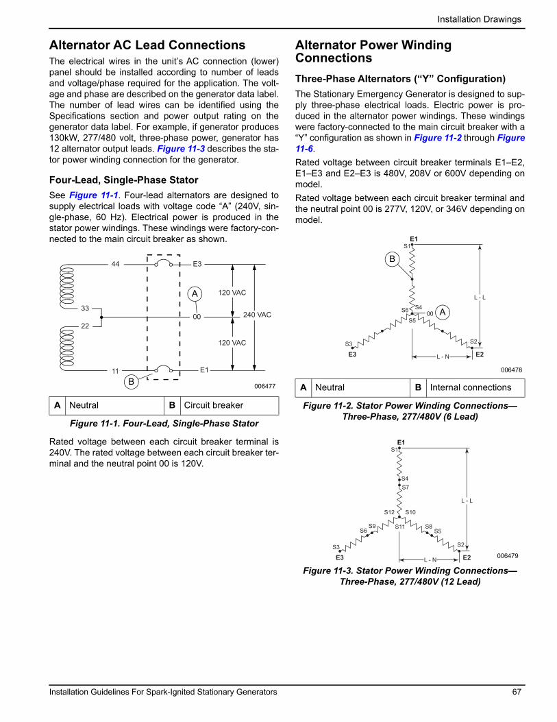
Installation Drawings
Alternator AC Lead ConnectionsThe electrical wires in the unit’s AC connection (lower) panel should be installed according to number of leads and voltage/phase required for the application. The volt-age and phase are described on the generator data label. The number of lead wires can be identified using the Specifications section and power output rating on the generator data label. For example, if generator produces 130kW, 277/480 volt, three-phase power, generator has 12 alternator output leads. Figure 11-3 describes the sta-tor power winding connection for the generator.
Four-Lead, Single-Phase StatorSee Figure 11-1. Four-lead alternators are designed to supply electrical loads with voltage code “A” (240V, sin-gle-phase, 60 Hz). Electrical power is produced in the stator power windings. These windings were factory-con-nected to the main circuit breaker as shown.
Figure 11-1. Four-Lead, Single-Phase Stator
Rated voltage between each circuit breaker terminal is 240V. The rated voltage between each circuit breaker ter-minal and the neutral point 00 is 120V.
Alternator Power Winding ConnectionsThree-Phase Alternators (“Y” Configuration)The Stationary Emergency Generator is designed to sup-ply three-phase electrical loads. Electric power is pro-duced in the alternator power windings. These windings were factory-connected to the main circuit breaker with a “Y” configuration as shown in Figure 11-2 through Figure 11-6.Rated voltage between circuit breaker terminals E1–E2, E1–E3 and E2–E3 is 480V, 208V or 600V depending on model.Rated voltage between each circuit breaker terminal and the neutral point 00 is 277V, 120V, or 346V depending on model.
Figure 11-2. Stator Power Winding Connections—Three-Phase, 277/480V (6 Lead)
Figure 11-3. Stator Power Winding Connections—Three-Phase, 277/480V (12 Lead)
A Neutral B Circuit breaker
44
120 VAC
240 VAC
120 VAC
E3
E1
0033
22
11
006477
A
B A Neutral B Internal connections
E1S1
S6
S5
S4
S2
E2S3
E3 L - N
L - L
00
006478
B
A
E1S1
S4S7
S12
S11
S10
S8S5
S2
E2
S9S6
S3
E3 L - N
L - L
006479
Installation Guidelines For Spark-Ignited Stationary Generators 67

Installation Drawings
Figure 11-4. Stator Power Winding Connections—Three-Phase, 120/208V (6 Lead)
Figure 11-5. Stator Power Winding Connections—Three-Phase, 120/208V (12 Lead)
Figure 11-6. Stator Power Winding Connections—Three-Phase, 346/600V (6 Lead)
Three-Phase Alternators (“Delta” Configuration)The Stationary Emergency Generator is designed to sup-ply three-phase electrical loads. Electric power is pro-duced in the alternator power windings. These windings were factory-connected to the main circuit breaker with a “Delta” configuration as shown in Figure 11-7 and Figure 11-8.Rated voltage between circuit breaker terminals E1–E2, E1–E3 and E2–E3 is 240V.Rated voltage between E2 and the neutral point 00 is 208V. The rated voltage E1–00 and E3–00 is approxi-mately 120V.
NOTE: Voltage measured from E2 to 00 can greatly vary when single-phase load is placed on alternator.
Figure 11-7. Stator Power Winding Connections—Three-Phase, 120/240V (6 Lead)
Figure 11-8. Stator Power Winding Connections—Three-Phase, 120/240V (12 Lead)
A Neutral B Internal connections
A Neutral B Internal connections
E3 E2
00
E1
L-L
L-N
S1 S1
S4 S4
S6
S6S3
S3
S5
S5 S2
S2006480
B
A
E3 E2
E1
L-L
L-N
S7 S1
S10 S4
S12
S6S9
S3
S5
S11 S2
S8 006481
E1S1
S6
S5
S4
S2
E2S3
E3 L - N
L - L
00
006482
B
A
B Internal connections
006483
B
240 VAC
120 VAC 120 VAC
240 VAC240 VAC
S2 S12
S11
S1NB
S10
S3E1 E3
E2
S5
S8
S9
S6
208 VAC
006484
68 Installation Guidelines For Spark-Ignited Stationary Generators

Installation Drawings
Alternator Wiring Diagram(1 of 4)
Installation Guidelines For Spark-Ignited Stationary Generators 69

Installation Drawings
Alternator Wiring Diagram(2 of 4)
70 Installation Guidelines For Spark-Ignited Stationary Generators

Installation Drawings
Alternator Wiring Diagram(3 of 4)
Installation Guidelines For Spark-Ignited Stationary Generators 71
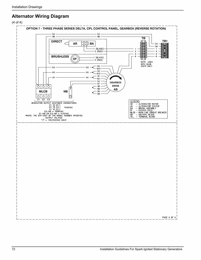
Installation Drawings
Alternator Wiring Diagram(4 of 4)
72 Installation Guidelines For Spark-Ignited Stationary Generators

Installation Drawings
This page intentionally left blank.
Installation Guidelines For Spark-Ignited Stationary Generators 73

Installation Drawings
This page intentionally left blank.
74 Installation Guidelines For Spark-Ignited Stationary Generators


Part No. 0K8419 Rev. F 06/11/19©2019 Generac Power Systems, Inc.All rights reservedSpecifications are subject to change without notice.No reproduction allowed in any form without prior written consent from Generac Power Systems, Inc.
Generac Power Systems, Inc.S45 W29290 Hwy. 59Waukesha, WI 53189
1-888-GENERAC (1-888-436-3722)www.generac.com
®