ge1500 series - 150 mhz - tequipment.net lowest … damages, whether in contract or otherwise....
TRANSCRIPT

Oscilloscope ProbeSonde pour OscilloscopeTastkopf für Oszilloskop
GE1500 Series - 150 MHzGE1501GE1511GE1512GE1521
GE1502GE1511RAGE1512RAGE1522

ELDITEST
© 2010 All rights reserved.
Elditest is a trademark of Sefram Instruments and Systems.
Elditest products are covered by US and foreign patents, issued and pending. In-formation in this publication supersedes all earlier versions. Specifications sub-ject to change without notice.
For product information, sales, service and technical support:• In North America, call +1-714-221-9330 or visit www.caltestelectronics.com• In Europe, call +33 (0)825 56 50 50 or visit www.sefram.fr
GE1501 1x 1 45 30 11 1.2 -
GE1502 1x 1 65 21 17 2.0 -
GE1511 10x 10 12 150 2.3 1.2 10 - 30
GE1511RA 10x 10 12 150 2.3 1.2 10 - 30
GE1512 10x 10 14 135 2.6 2.0 10 - 30
GE1512RA 10x 10 14 135 2.6 2.0 10 - 30
GE1521 1x/10x 1/10 45/12 17/150 20/2.3 1.2 10 - 30
GE1522 1x/10x 1/10 65/14 13/135 20/2.3 2.0 10 - 30
Input CompensationModel Attn. Imped. B/W Rise Time Length Range
R (MΩ) C (pF) (MHz) (ns) (m) (pF)
Model Number & Specifications
(RA = Readout Actuator or Sense Pin)
2

ELDITEST
Elditest warrants its probes for normal use and operation within specification for aperiod of one (1) year from the date of shipment (accessories and manual not in-cluded).
In exercising its warranty, Elditest, at its option, will either repair or replace any as-sembly returned within the warranty period. However, this will be done only if theproduct is determined by Elditest’s examination to be defective because of work-manship or materials, and the defect is not caused by misuse, neglect, accident,abnormal conditions of operation, or damaged by attempted repair or modifica-tions by non-authorized facility.
The customer will be responsible for the transportation and insurance charges forthe return of products.
This warranty replaces all other warranties, expressed or implied, including, butnot limited to, any implied warranty of merchantability, fitness, or adequacy for anyparticular purpose or use. Elditest shall not be liable for any special, incidental orconsequential damages, whether in contract or otherwise.
Warranty
This electronic product is subject to disposal and recycling regulationsthat vary by country and region. Many countries prohibit the disposalof waste electronics equipment in standard waste receptacles.
RoHScompl i a n t
2 0 0 2 / 9 5 / E C
Made in Taiwan3

ELDITEST
To avoid personal injury and to prevent fire or damage to the probe or any productconnected to it, review and comply with the following safety precautions.
Use of this probe or test instrument it is connected to in a manner not specified bythe manufacturers may impair protection mechanisms.
Connect to properly grounded instruments. Use only with test instruments havingtheir BNC input connected to earth ground. Do not connect the probe ground ter-minal to any point which is at a potential other than earth ground.
Do not disconnect the probe from instrument during measurement. Connect theprobe to the measurement instrument before connecting the probe to the test cir-cuit.
Do not apply to the input any potential that exceeds the maximum rating of theprobe.
Comply with the voltage derating curve. When measuring higher frequency sig-nals, be sure to comply with the Voltage vs Frequency Derating Curve.
Do not remove probe casing. Removal of the probe’s casing may expose you toelectric shock.
Do not use if any part is damaged. All maintenance should be referred to a quali-fied service personnel only.
Do not use in wet or explosive atmospheres.
For indoor use only.
General Safety Information
To avoid Personal Injury and Product Damage:
WARNING . Warning statements identify conditions or practices that could result ininjury or loss of life.
Symbols and Terms
CAUTION. Caution statements identify conditions or practices that could result indamage to this product or other property.
These terms may appear in this manual:
The following symbols may appear on the product:
DANGER
High VoltageATTENTION
Refer to ManualDOUBLE
INSULATION
Protective(EARTH) TERMINAL
4
ELDITEST
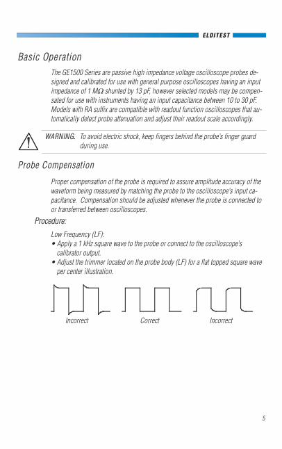
Basic OperationThe GE1500 Series are passive high impedance voltage oscilloscope probes de-signed and calibrated for use with general purpose oscilloscopes having an inputimpedance of 1 MΩ shunted by 13 pF, however selected models may be compen-sated for use with instruments having an input capacitance between 10 to 30 pF.Models with RA suffix are compatible with readout function oscilloscopes that au-tomatically detect probe attenuation and adjust their readout scale accordingly.
Probe Compensation
Proper compensation of the probe is required to assure amplitude accuracy of thewaveform being measured by matching the probe to the oscilloscope’s input ca-pacitance. Compensation should be adjusted whenever the probe is connected toor transferred between oscilloscopes.
Low Frequency (LF):• Apply a 1 kHz square wave to the probe or connect to the oscilloscope’s
calibrator output.• Adjust the trimmer located on the probe body (LF) for a flat topped square wave
per center illustration.
Procedure:
Incorrect Correct Incorrect
WARNING. To avoid electric shock, keep fingers behind the probe’s finger guardduring use.
5

ELDITEST
Attenuation Ratio . . . . . . . . . . . . . 1x (1:1); 10x (10:1) & 1x/10x (1:1 / 1:10) 10:1±0.5%Bandwidth . . . . . . . . . . . . . . . . . . see tableRise Time . . . . . . . . . . . . . . . . . . . see tableInput Resistance . . . . . . . . . . . . . . see table (used with oscilloscope with 1 MΩ input)Input Capacitance . . . . . . . . . . . . . see tableCompensation Range . . . . . . . . . . see table
Max. Input Voltage . . . . . . . . . . . . 600 V CAT I, 300 V CAT II (DC + peak AC)Derated with Frequency (see Derating Curve)
Pollution Degree 2Max. Operating Temp . . . . . . . . . . 0° to +50° CHumidity . . . . . . . . . . . . . . . . . . . . 85% RH or less (at 35° C)Cable Length . . . . . . . . . . . . . . . . see tableDefinitions:Measurement Category I (CAT I) is for measurements performed on circuits not directly connected to mains.Measurement Category II (CAT II) is for measurements performed on circuits directly connected to the low voltage in-stallation. Examples are on household appliances, portable tools and similar equipment.Pollution Degree 2 refers to an operation environment where normally only dry non-conductive pollution occursTemporary conductivity caused by condensation must be expected.
Low Voltage Directive(LVD) 93/68/EEC(and 73/23/EEC)
EN 61010-031:2000Type C probe assembly
Specifications [EC Declaration of Conformity]
10 KHz0 V
100 V
200 V
300 V
400 V
500 V
600 V
700 V
100 KHz 1 MHz 1 GHz10 MHz 100 MHz
Voltage vs Frequency Derating Curve
WARNING. Do not apply to the input any potential that exceeds the maximumratings of the probe .
6

ELDITEST
1 Sprung Hook, 5 mm, Black CT2709A-0 1
2 GND Lead w/Alligator Clip CT2710-12-0 1
3 BNC Adapter, 5 mm CT2708 1
4 Replacement Tip, Black CT2711A-0 1
5 *Deluxe Trimmer Tool CT3648 1
6 IC Tip Insulator, 5 mm, Black CT2713A-0 1
7 Tip Insulator, 5 mm, Black CT2712A-0 1
8 Identifier Rings CT3662 1
9 *Probe Tip GND CT2714 1
Itm. Description Model Quantity
Replaceable Parts
* Not included with 1x probes.
GE1500
134
56
7
89
2
X10
7

Use the following guidelines:• Clean only the exterior of the probe, cables and accessories. Use a soft cotton
cloth moistened with a mild detergent and water solution. Do not allow anyportion of the probe to be submerged at any time.
• Dry the probe and accessory thoroughly before attempting to make any voltagemeasurement.
• Do not subject the probe to solvents or solvent fumes as these can cause deteri-oration of the probe body, cables and accessories.
For Elditest oscilloscope probes:
North America:Cal Test Electronics, Inc.22820 Savi Ranch Pkwy.Yorba Linda, CA 92887-4610 USATel : 714-221-9330Fax : 714-921-9849E-mail : [email protected] : www.caltestelectronics.com
Europe:SEFRAM Instruments et Systèmes32, rue E. MARTEL BP55F 42009 – SAINT-ETIENNE Cedex 2 FranceTel : +33 (0)825 56 50 50 (0,15€TTC/mn)Fax : +33 (0)4 77 57 23 23E-mail : [email protected] : www.sefram.fr
User Man GE1500_r05
Cleaning
ELDITEST
8

Oscilloscope ProbeSonde pour OscilloscopeTastkopf für Oszilloskop
GE1500 Série - 150 MHz
9

ELDITEST
© 2010 Tous droits réservés.
Elditest est une marque déposée de Sefram Instruments et Systèmes.
Les produits Elditest font l’objet de brevets déposés ou en cours. Les informationsprésentes dans ce manuel remplacent toutes les informations antérieures. Les spé-cifications peuvent être modifiées sans préavis.
Pour obtenir des informations, le SAV ou le support technique:• In North America, call +1-714-221-9330 or visit www.caltestelectronics.com• En Europe, appelez le +33 (0)825 56 50 50 ou visitez www.sefram.fr
GE1501 1x 1 45 30 11 1.2 -
GE1502 1x 1 65 21 17 2.0 -
GE1511 10x 10 12 150 2.3 1.2 10 - 30
GE1511RA 10x 10 12 150 2.3 1.2 10 - 30
GE1512 10x 10 14 135 2.6 2.0 10 - 30
GE1512RA 10x 10 14 135 2.6 2.0 10 - 30
GE1521 1x/10x 1/10 45/12 17/150 20/2.3 1.2 10 - 30
GE1522 1x/10x 1/10 65/14 13/135 20/2.3 2.0 10 - 30
Imp Temps CompensationModèle Attn. d’entrée Bande de monté Longueur Gamme
R (MΩ) C (pF) (MHz) (ns) (m) (pF)
Référence & Spécifications
(RA = dispositif pour readout sur l’oscilloscope)
10

ELDITEST
Elditest garantit la sonde pour un usage normal ainsi que son fonctionnementdans les limites des spécifications pour une durée de un (1) an à partir de la dated’expédition (accessoires et manuel non inclus et non garantis).
Pour exercer la garantie, Elditest choisira, soit de réparer soit de remplacer toutproduit retourné pendant la période de garantie. Cependant, cela sera fait que si l’-expertise effectuée par Elditest détermine que le défaut du produit est dû à unemalfaçon ou aux matériaux utilisés dans le produit, et non pas à un mauvaisusage, une négligence, un accident, des conditions d’utilisation anormales, undommage causé par une tentative de réparation ou par des modifications faites auproduit.
Consultez nos conditions générales de garantie.
Cette garantie remplace toute autre garantie existante. Elditest ne peut en aucuncas être tenu responsable des conséquences liées à l’utilisation des sondes, quel’utilisation soit normale ou hors du champ d’application spécifié dans ce manuel.
Garantie
Ce produit électronique est sujet à une réglementation de traitement etde recyclage qui varie suivant les régions et les pays. De nombreuxpays interdisent la mise au rebut des déchets électroniques dans despoubelles ou les décharges à usage domestique.
RoHScompl i a n t
2 0 0 2 / 9 5 / E C
Fabriqué à Taiwan11

ELDITEST
Pour éviter tout risque pour l’utilisateur d’endommager la sonde ou l’oscilloscopesur lequel la sonde est branchée, il est important de lire les informations de sécu-rité.
L’utilisation de la sonde ou de l’instrument sur lequel elle est connecté doit êtrefait conformément aux recommandations du fabriquant.
Ne brancher la sonde que sur un instrument relié à la terre. N’utiliser cette sondeque sur des prises BNC reliées à la terre. Ne jamais brancher la connexion demasse de la sonde à un potentiel autre que la terre.
Ne pas déconnecter la sonde de l’instrument pendant les mesures. Toujoursbrancher la sonde à l’instrument avant de la connecter à l’application.
Ne jamais appliquer de tension supérieure au maximum autorisé dans les spécifi-cations de la sonde.
Restez dans les limites de la courbe tension/fréquence. Lorsque vous mesurez dessignaux de fréquences élevées, il est impératif de rester dans les limites spécifiées.
Ne jamais ouvrir le corps de la sonde. Tenter d’accéder à l’électronique internevous expose à des risques de choc électrique.
Ne pas utiliser la sonde si elle est endommagée. Toute maintenance ou réparationdoit être réalisée par du personnel qualifié et habilité.
Ne pas utiliser en humidité excessive ou en atmosphère explosive.
Utilisation à l’intérieur uniquement.
Prescriptions de sécurité
Pour éviter tout risque pour l’utilisateur ou pour la sonde:
DANGER . Ce terme est utilisé pour des conditions qui peuvent conduire à desblessures ou des risques mortels.
Symboles et termes utilisés
ATTENTION. Ce terme est utilisé pour des conditions pouvant endommager lasonde ou le matériel.
Les termes suivants peuvent apparaitre dans le manuel:
Les symboles suivants peuvent être utilisé sur le produit:
DANGER
Haute tensionATTENTION
Se référer au manuelDOUBLE
ISOLEMENT
Terre deprotection
12

ELDITEST
Mise en œuvreLes sondes de la série GE1500 sont des sondes de type passif, conçues pour êtreutilisées avec des oscilloscopes ayant une impédance d’entrée de 1 MΩ shuntépar 13 pF. Il est cependant possible de compenser toute capacité d’entrée com-prise entre 10pF et 30pF. Les modèles avec l’extension RA sont compatibles avecles fonctions « readout » des oscilloscopes, qui détectent automatiquement l’at-ténuation des sondes et affichent l’amplitude du signal en conséquence.
Compensation de la sonde
La compensation de la sonde est nécessaire pour garantir la caractéristique enfréquence et la spécification d’amplitude du signal. Cette compensation doit sefaire en fonction de la capacité d’entrée de l’oscilloscope et est nécessaire àchaque fois qu’on change l’oscilloscope ou la voie de l’oscilloscope.
Basse Fréquence (BF):• Appliquer un signal carré de fréquence 1kHz à la sonde ou la connecter au sig-
nal de calibration de l’oscilloscope.• Régler le condensateur situé sur le corps de la sonde (BF) pour obtenir un palier
plat comme indiqué sur le schéma.
Procedure:
Incorrect Correct Incorrect
DANGER. Pour éviter tout risque de choc électrique, il est impératif de garder lesdoigts en amont de l’anneau de garde.
13

ELDITEST
Rapport d’atténuation . . . . . . . . . . 1x (1:1); 10x (10:1) & 1x/10x (1:1 / 1:10) 10:1±0.5%Bande passante . . . . . . . . . . . . . voir tableauTemps de montée . . . . . . . . . . . . . voir tableauRésistance d’entrée . . . . . . . . . . . . voir tableau (à utiliser avec des oscilloscopes d’imp dance 1 MΩ)
Capacité d’entrée . . . . . . . . . . . . . voir tableauGamme de compensation . . . . . . . voir tableau
Tension max. d’entrée . . . . . . . . . . 600 V CAT I, 300 V CAT II (DC + peak AC)Relation Tension/Fréquence (voir courbe Tension/Fréquence)
Degré de pollution 2Température de fonctionnement . . 0° à 50°CHumidité . . . . . . . . . . . . . . . . . . . 85% max de HR (à 35° C)Longueur du câble . . . . . . . . . . . . voir tableauDéfinitions:La catégorie d’installation I (CAT I) est définie pour les mesures à faire sur des circuits qui ne sont pas reliés directe-ment au secteur.La catégorie d’installation II (CAT II) est définie pour les mesures à faire sur le secteur basse tension. Exemple :équipements domestiques, outillage portable, etc.Le degré de pollution 2 se réfère à une utilisation ou la pollution est uniquement sèche et non conductrice.Une conduction momentanée en présence d’humidité peut être possible.
Directive Basse Tension(DBT) 93/68/EEC(et 73/23/EEC)
EN 61010-031:2000Type C
Spécifications [Déclaration CE]
10 KHz0 V
100 V
200 V
300 V
400 V
500 V
600 V
700 V
100 KHz 1 MHz 1 GHz10 MHz 100 MHz
Courbe de relation Tension / Fréquence
DANGER. Ne jamais appliquer une tension supérieure à la tension maximum au-torisée dans les spécifications de la sonde.
14

ELDITEST
1 Embout grippe-fil, 5mm, noir CT2709A-0 1
2 Câble de masse avec pince croco CT2710-12-0 1
3 Adaptateur BNC, 5 mm CT2708 1
4 Pointe de remplacement, noire CT2711A-0 1
5 *Tournevis de réglage CT3648 1
6 Capuchon isolant pour CI, 5mm, noir CT2713A-0 1
7 Capuchon isolant, 5mm, noir CT2712A-0 1
8 Bagues de couleur CT3662 1
9 *Ressort de masse CT2714 1
Type. Description Référence Quantité
Pièces détachées
* non livré avec les sondes x1
GE1500
134
56
7
89
2
X10
15

Pour les accessories Elditest :
North America:Cal Test Electronics, Inc.22820 Savi Ranch Pkwy.Yorba Linda, CA 92887-4610 USATel : 714-221-9330Fax : 714-921-9849E-mail : [email protected] : www.caltestelectronics.com
Europe:SEFRAM Instruments et Systèmes32, rue E. MARTEL BP55F 42009 – SAINT-ETIENNE Cedex 2 FranceTel : +33 (0)825 56 50 50 (0,15€TTC/mn)Fax : +33 (0)4 77 57 23 23E-mail : [email protected] : www.sefram.fr
User Man GE1500_r05
NettoyageRecommandations:• Nettoyez uniquement le corps de la sonde, le câble et les accessoires. Utiliser
un chiffon doux et humide, avec une solution savonneuse. Ne jamais tremperou immerger une quelconque partie de la sonde.
• Assurez-vous que la sonde soit parfaitement sèche avant toute mesure.• Ne jamais mettre en contact la sonde avec des solvants qui pourraient endom-
mager le corps de sonde, le câble ou les accessoires.
ELDITEST
16

Oscilloscope ProbeSonde pour OscilloscopeTastkopf für Oszilloskop
GE1500 Serie - 150 MHz
17
ELDITEST
© 2010 Alle Rechte vorbehalten.
Elditest ist ein Warenzeichen der Firma Sefram Instrumente und Systeme.
Sämtliche Elditest Produkte sind durch US- und ausländischen Patente geschützt,die entweder erteilt oder angemeldet sind. Die Information in dieser Informations-schrift ersetzt alle vorhergehenden Versionen. Änderung der Spezifikationen vor-behalten.
Für Wareninformation, Verkauf, Service und technische Kundenbetreuung wendenSie sich bitte an:• In Nord Amerika, Telefon Nr: +1-714-221-9330 oder besuchen Sie www.cal-
testelectronics.com• In Europa, Telefon Nr: +33 (0)825 56 50 50 oder besuchen Sie www.sefram.fr
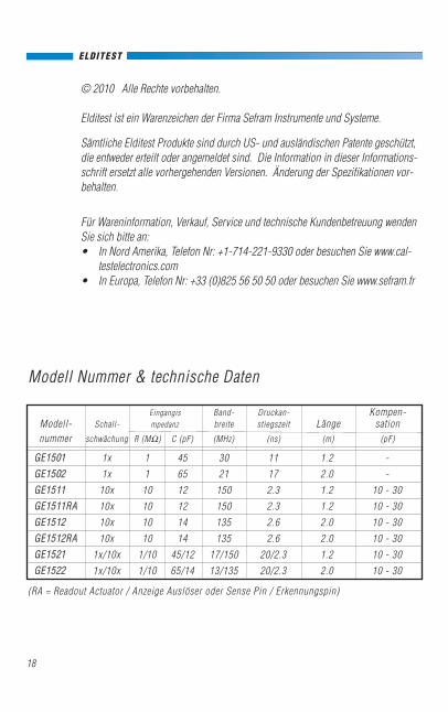
GE1501 1x 1 45 30 11 1.2 -
GE1502 1x 1 65 21 17 2.0 -
GE1511 10x 10 12 150 2.3 1.2 10 - 30
GE1511RA 10x 10 12 150 2.3 1.2 10 - 30
GE1512 10x 10 14 135 2.6 2.0 10 - 30
GE1512RA 10x 10 14 135 2.6 2.0 10 - 30
GE1521 1x/10x 1/10 45/12 17/150 20/2.3 1.2 10 - 30
GE1522 1x/10x 1/10 65/14 13/135 20/2.3 2.0 10 - 30
Eingangis Band- Druckan- Kompen-Modell- Schall- mpedanz breite stiegszeit Länge sationnummer schwächung R (MΩ) C (pF) (MHz) (ns) (m) (pF)
Modell Nummer & technische Daten
(RA = Readout Actuator / Anzeige Auslöser oder Sense Pin / Erkennungspin)
18

ELDITEST
Elditest gewährt eine Garantie von einem (1) Jahr, beginnend mit dem Tag derLieferung, für die gelieferte Ware unter normaler Nutzung und Betrieb (Zubehörund Bedienungsanleitung nicht enthalten).
Bei Geltungmachung der Garantie wird Elditest -nach eigenem Ermessen - ent-weder den fehlerhaften Teil ersetzen oder reparieren, wenn er innerhalb derGarantiezeit zurückgeschickt wird. Das wird jedoch nur der Fall sein, wenn Unter-suchungen von Elditest zeigen, dass diese Mangelhaftigkeit entweder durchhandwerkliche Ausführung oder fehlerhafte Materialien entstanden ist und nichtdurch Missbrauch, Vernachlässigung, Unfall, irreguläre Betriebsbedingungen oderdurch Reparaturversuche oder Modifizierungen durch Unbefugte.
Bei Rücksendung der Ware zahlt der Kunde die Transportgebühr sowie die Gebührfür Versicherung.
Diese Garantie ersetzt alle anderen Garantien, ausdrücklich oder besagt, ein-schließlich, aber nicht beschränkt auf, die allgemeine Gebrauchstauglichkeit,Tauglichkeit, der Eignung für einen bestimmten Zweck oder Nutzen. Elditest haftetnicht für etwaige besonderen, beiläufigen oder Folgeschäden aus dem Vertragoder anderweitig.
Garantie
Dieses elektronische Produkt unterliegt den Entsorgungs- und Recyc-ling-Verordnungen, die nach Land und Region variieren. Viele Länderverbieten die Entsorgung von elektronischen Geräten in Standard-Müllbehältern.
RoHScompl i a n t
2 0 0 2 / 9 5 / E C
Hergestellt in Taiwan19
Um Verletzungen, Feuer oder Schaden an dem Tastkopf oder einem Produkt, das mit demTastkopf in Kontakt steht, zu vermeiden, bitten wir Sie die folgenden Sicherheitshinweise zuüberprüfen und einzuhalten.
Beim Einsatz dieses Tastkopfes oder dieses Prüfgerätes darf dieses Gerät nur soangeschlossen werden, wie es von dem Hersteller angegeben ist, sonst wäre es möglich, dassdie Schutzvorrichtungen beeinträchtigt werden.
Anschluss nur an richtig geerdet Instrumente. Verwenden Sie diese nur mit Prüfgeräten, derenBNC-Input geerdet ist. Der Erdkontakt des Tastkopfes darf nirgendwo angeschlossen werden,wo die Möglichkeit besteht, dass die Klemmen anderweitig geerdet sind.
Während der Messung darf der Tastkopf nicht von dem Messgerät getrennt werden. SchließenSie den Tastkopf an das Messgerät an bevor Sie den Tastkopf an den Prüfstromkreis an-schließen.
Schliessen Sie an den Input kein Potential an, das die maximale Belastbarkeit des Tastkopfesüberschreitet.
Halten Sie die herabgesetzte Spannungskurvenform ein. Bei der Messung der höheren Fre-quenz Signale, versichern Sie sich, dass die Spannung im Vergleich zu der Frequenzkurven-form eingehalten wird.
Das Tastkopfgehäuse darf nicht entfernt werden. Wenn das Tastkopfgehäuse entfernt wird,besteht die Möglichkeit, dass man einen Stromschlag erhält.
Wenn irgendein Teil beschädigt ist, darf das Instrument nicht verwendet werden. AlleWartungsarbeiten sollten nur von qualifiziertem Fachpersonal durchgeführt werden.
Nicht in nasser oder explosiver Atmosphäre verwenden.
Darf nur im Innenbereich verwendet werden.
ELDITEST
Allgemeine Sicherheitsinformation
Vermeidung von Verletzungen und Gefahr von Schäden an den Produkten:
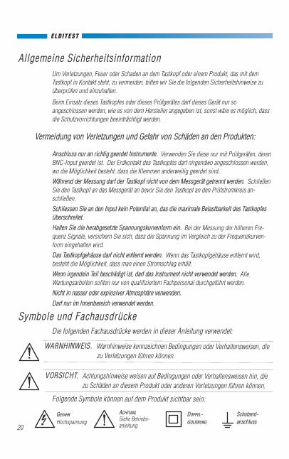
WARNHINWEIS. Warnhinweise kennzeichnen Bedingungen oder Verhaltensweisen, diezu Verletzungen führen können.
Symbole und Fachausdrücke
VORSICHT. Achtungshinweise weisen auf Bedingungen oder Verhaltensweisen hin, diezu Schäden an diesem Produkt oder anderen Verletzungen führen können.
Die folgenden Fachausdrücke werden in dieser Anleitung verwendet:
Folgende Symbole können auf dem Produkt sichtbar sein:
GEFAHR
Hochspannung
ACHTUNG
Siehe Betriebs-anleitung
DOPPEL-ISOLIERUNG
Schutzerd-anschluss
20

ELDITEST
ArbeitsvorgangDie GE1500 Serien sind passive hochimpedante Spannungs-Tastköpfe für Oszilloskope;gestaltet und kalibriert für den Einsatz mit Mehrzweck-Oszilloskopen mit einer Eingangsim-pedanz von 1 MΩ überbrückt mit 13 pF; ausgewählte Modelle können jedoch für den Einsatzmit Instrumenten mit einer Eingangskapazität zwischen 10 bis 30 pF ausgeglichen werden.Modelle mit RA-Suffix sind kompatibel mit Oszilloskopen mit Sichtanzeige, die die Tastkopf-abschwächung automatisch erkennen und die Ausleseanzeige entsprechend regulieren.
Tastkopf Kompensation
Angemessener Ausgleich des Tastkopfes ist erforderlich, um die Amplitudenge-nauigkeit der Wellenform, die gemessen wird, zu garantieren, indem man denTastkopf mit der Eingangsimpendanz des Oszilloskops übereinstimmt. Die Kom-pensation soll jedes Mal korrigiert werden, wenn der Tastkopf angeschlossen wirdoder zwischen Oszilloskopen transferiert wird.
Niederfrequenz: (NF):• Setzen Sie eine 1 kHz Rechteckwelle an den Tastkopf oder schließen Sie den
Tastkopf an den Kalibratorausgang des Oszilloskops an.• Stellen Sie den Trimmer, der sich auf dem Tastkopfkörper (NF) befindet, für eine
flache Rechteckwelle ein – wie es in der Mitte der Abbildung gezeigt wird.
Arbeitsablauf:
Falsch Richtig Falsch
WARNHINWEIS . Um Stromschlag zu vermeiden, achten Sie darauf, dass währenddes Gebrauches die Finger hinter dem Fingerschutz sind.
21

ELDITEST
Abschwächungsverhältnis . . . . . . 1x (1:1); 10x (10:1) & 1x/10x (1:1 / 1:10) 10:1±0.5%Bandbreite . . . . . . . . . . . . . . . . . . siehe TabelleAnstiegszeit . . . . . . . . . . . . . . . . . siehe TabelleEingangswiderstand . . . . . . . . . . siehe Tabelle (wird mit Oszilloskop mit 1 MΩ Input verwendet)
Eingangskapazität . . . . . . . . . . . . . siehe TabelleKompensationsbereich . . . . . . . . . siehe Tabelle
Maximale Eingangsspannung . . . 600 V CAT I, 300 V CAT II (DC + peak AC)Eingeschränkt durch Frequenz (siehe Derating Kurve)
Verschmutzungsgrad 2Maximale Betriebstemperatur . . . 0° to +50° CFeuchtigkeit . . . . . . . . . . . . . . . . . 85% RH oder weniger (bei 35° C)Kabellänge . . . . . . . . . . . . . . . . . . siehe TabelleDefinitionen:Messkategorie I (CAT I) ist für Schaltkreis-Messungen, die nicht direkt an das Stromnetz angeschlossen sind.Messkategorie II (CAT II) ist für Schaltkreis-Messungen, die direkt an die Niederspannungsanlage angeschlossen sind.Beispiele wären Haushaltsgeräte, tragbare Elektrowerkzeuge und Ähnliches.Verschmutzungsgrad 2 bezieht sich auf eine Betriebsumgebung, wo normalerweise nur trockene, nicht leitfähige Ver-schmutzung auftritt.Es muss mit vorübergehender Leitfähigkeit, die durch Kondenswasser entsteht, gerechnet werden.
Niederspannungsrichtlinie(LVD) 93/68/EEC(und 73/23/EEC)
EN 61010-031:2000Typ C Tastkopfanordnung
Technische Daten [EG Konformitätserklärung]
10 KHz0 V
100 V
200 V
300 V
400 V
500 V
600 V
700 V
100 KHz 1 MHz 1 GHz10 MHz 100 MHz
Spannungs / Frequenz Derating Kurve
WARNHINWEIS . Es darf kein Potenzial, das den Maximalwert der Sonde überschrei-tenn, an den Input angeschlossen werden.
22

ELDITEST
1 Klemmhaken, 5 mm, schwarz CT2709A-0 1
2 Masseleitung mit Krokodilklemme CT2710-12-0 1
3 BNC-Adapter, 5 mm CT2708 1
4 Ersatzspitze, schwarz CT2711A-0 1
5 *Spezial-Abgleichschlüssel CT3648 1
6 IC-Isolierkappe, 5 mm, schwarz CT2713A-0 1
7 Isolierkappe, 5 mm, schwarz CT2712A-0 1
8 Kennzeichnungsringe CT3662 1
9 *Sondenspitze GND CT2714 1
Art. Beschreibung Modell Stückzahl
Austauschteile
* Nicht im 1x Tastkopf Lieferumfang enthalten.
GE1500
134
56
7
89
2
X10
23

Bitte halten Sie die folgenden Richtlinien ein:• Reinigen Sie nur die Aussenseite des Tastkopfes, der Kabeln und des Zubehörs.
Verwenden Sie ein weiches Baumwolltuch mit einem milden Reinigungsmittelund Wasser. Niemals darf ein Teil des Tastkopfes untergetaucht werden.
• Vor der Spannungsmessung müssen der Tastkopf und das Zubehör sorgfältiggetrocknet werden
• Der Tastkopf darf nicht mit Lösungsmitteln oder Lösemitteldämpfen in Kontaktkommen, da diese den Tastkopfkörper, sowie die Kabeln und das Zubehör zer-stören.
Für Elditest Tastköpfe für Oszilloskope:
Nord Amerika:Cal Test Electronics, Inc.22820 Savi Ranch Pkwy.Yorba Linda, CA 92887-4610 USATel : 714-221-9330Fax : 714-921-9849E-mail : [email protected] : www.caltestelectronics.com
Europa:SEFRAM Instruments et Systèmes32, rue E. MARTEL BP55F 42009 – SAINT-ETIENNE Cedex 2 FrankreichTel : +33 (0)825 56 50 50 (0,15€TTC/mn)Fax : +33 (0)4 77 57 23 23E-mail : [email protected] : www.sefram.fr
User Man GE1500_r05
Reinigung
ELDITEST
24