ge zenith zdec 2020 - ewing associates incorporated 2020 modular paralleling switchgear ge zenith...
TRANSCRIPT

g Power QualityDigital Energy
GE ZenithZDEC 2020Modular Paralleling Switchgear

ZDEC 2020 Has the Solution
Healthcare and Critical Facilities Demand GeneratorParalleling Systems that are…
• Flexible design compatible with multiplebrands of generator sets and powersection configurations
• Safe: Separately-mounted low voltagecontrols from the power section
• Modular construction, user-scaleableto changing facility needs
• Ease of operation: Traditional-styleannunciation and manual paralleling

ZDEC 2020: An Integral Component
GE UPS System� Energy Efficient SG Series� Compact Footprint� Redundant Parallel
Architecture™ (RPA™)
Life SafetyLoads
BusinessCriticalLoads
GE Zenith ZTE� High-Level Diagnostics� PQ Metering� High-Speed Event Log
Priority #2 ATS
Monitor: RS-485 or TCP/IP (Modbus)Control: Hardwired Gen Start Load Add Load Shed
Backup (Emergency) Supply
Em
erg
en
cy
Ge
ne
rato
rs(M
ult
iple
Ma
nu
fac
ture
rs)
Utility (Normal) Power
Power to the Load
Emergency (Backup) Power
Control and I/O
Wallmount Surge Protective Device (SPD)
TransferSwitch
UPS
TransferSwitch
Utility (Normal)
Supply
Utility Switchboardwith Integral Surge
Protective Device (SPD)
GE SPD System� Protect against lightning
and switching surges� UL 1449 3rd Edition
PLC Interface� Serial RS-485 (Modbus)� User-Customizable
Data Map in ZDEC 2020 Access in PLC
Building Management PLC
Building Automation System (BAS)
PC Interface� TCP/IP or RS-485 serial (Modbus) communications
� View screens on ZDEC via Web Browser
Generator Interface� Hardwired start signal
from ZDEC� Hardwired common alarm & shutdown to ZDEC
� NFPA alarms & details status via Modbus RS-485 or CAN network to set control (based on Gen mfg type)
ZDEC 2020 Modular Paralleling Switchgear
GE Zenith ZTE� High-Level Diagnostics� PQ Metering� High-Speed Event Log
Priority #1 ATS
Monitor: RS-485 or TCP/IP (Modbus)Control: Hardwired Gen Start
3

Flexible…Safe…Modular…Easy to Operate
Flexible • Compatible with multiple brands, sizes and types
of generator sets
• One ZDEC 2020 system communicates with multiple generator manufacturers without parts changes or hardware re-configuration to ZDEC controls
• Parallel generators with different kW ratings
• Full flexibility in the choice of breaker manufacturer,LV/MV, traditional or arc-resistant construction
Safe• Place the power section in restricted electrical
room or safe distance from operators to reducePPE and arc flash hazards
• The maximum voltage present on any terminal is 120V
• All terminals are “finger-safe”
• Control section can be placed in a location accessible and convenient for operators
• UL 891, UL 1558 Ratings
Field Modular and Scalable • Master/System Controls are pre-configured
for up to (6) generators and (32) transfer switches or breakers
• Rack-in/rack-out generator controls that are hot-pluggable*
• Master controls automatically recognize an added generator and permits simple touchscreen generator setup*
Ease of Operation• Integrated manual hardwired controls for
each generator
• Hardwired sync scope with LEDs for manual paralleling
• Large status LEDs located on the front door show the generator and system status at a distance, which are not compromised by touchscreen “screen saver” modes
Installing the Hot-Pluggable GeneratorControl Drawer Module
* Patent pending

ZDEC ControlsModular, Hardwired Backup and Color Touchscreen
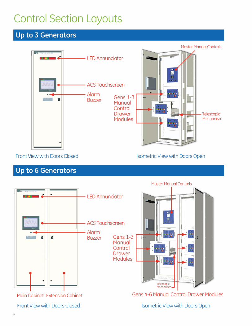
Control Section Layouts
LED Annunciator
ACS Touchscreen
Main Cabinet
Gens 1-3ManualControlDrawerModules
Gens 1-3ManualControlDrawerModules
Gens 4-6 Manual Control Drawer ModulesExtension Cabinet
LED Annunciator
ACS Touchscreen
Master Manual Controls
TelescopicMechanism
Alarm Buzzer
Alarm Buzzer
Master Manual Controls
Front View with Doors Closed Isometric View with Doors Open
Front View with Doors Closed Isometric View with Doors Open
TelescopicMechanism
Up to 3 Generators
Up to 6 Generators
6

1. Sync Lights: White Backlit LED
2. Synchroscope for Manual GeneratorSynchronization: Red LED Display
3. Generator Selector Switch for Manual Synchronization
4. LED Momentary Pushbutton to Silence the Horn
5. Light Test Pushbutton to Test all the LEDs on the Panel(s)
6. Auto-Man Switch for System
7. Master Reset Pushbutton to Acknowledge System Alarms/Shutdowns
AUTOOFF
ENGINE CONTROLSWITCH
BREAKER CONTROLSWITCH
MAN OPEN CLOSE
ENGINE RUN/COOL DOWN
LOWER RAISE LOWER RAISE
ALARM
VOLTAGE SPEED RESET
SHUTDOWN BREAKEROPEN
BREAKERCLOSED
BREAKERLOCKOUT
EMERGENCYSTOP
7
4
6 9 108 11 12
2
3
1
5
9"(229 mm)
13"(330 mm)
1. Engine Control Switch (OFF-AUTO-MAN)
2. Breaker Control Switch: Manual SpringReturn Selector Switch
3. Breaker Closed Status: Red Backlit LED
4. Breaker Lockout Status: White Backlit LED
5. Emergency Stop Pushbutton (Safety Cover)
6. Engine Run/Cool Down: Green Backlit LED
7. Manual Voltage Raise/Lower Spring Return Selector Switch
8. Engine Summary Alarm: Yellow Backlit LED
9. Manual Speed Raise/Lower Spring Return Selector Switch
10. Engine Shutdown Alarm: Red Backlit LED
11. Breaker Open Status: Green Backlit LED
12. Generator Reset Pushbutton
SYSTEM AUMSSWITCH
RESET
MANAUTO
GEN SYNC SWITCH
SYNC LIGHTS
OFF
G4
G1
G2
G3
G6
G5
HORN SILENCE LIGHT TEST
1
2
3
5
4
15"(381 mm)
13"(330 mm)
6
7
7
SystemNot inAuto
Any EngineStart Signal
Received
SummaryShutdown
SummaryAlarm
Non-EmerMode
Activated
Any EngineComms.Failure
Any EngineControl
Fuse Blown
ControlPower Fuse
Blown
AuxiliaryPowerFailure
Hardwired ControlsLED Annunciator
Master Control
Generator Controls (Typ.)

8
Advanced Control System (ACS)
Configuration Main Navigation
Generator systemexerciser/setup is simple and intuititive
User selection of start/stop times and test mode (test with load, test no load)
Simple checkbox to inhibit exercising on any given day - without re-programming of parameters
System Control Screen
Load Control Screen
Generator Optimization Screen
Plant Exerciser Screen
Menu Screen
Mimic Screen
System Control Screen
Lo dad Contr lol Screen
Selection of Test Modes (online, offline, load bank)
Settings for engine cool-down, minimum run timers, and minimum number of generators online
Set load priorities based on generatorbus load levels
Manual shed and add individual loads
Reset and re-addany shed loads
Embedded login/password protection
Single-button navigation to all sub-screens
Real-time values of reserve capacity (online kW - system kW demand)
Set time delays and threshold parameters to control the automatic starting/stopping of generator sets in response to system kW demand
Generator Optimization Screen
Pl t E i S
Mimic Screen
View system mode (standby/off, test, emergency) and gen status (running, off, cooldown) on one screen
Summary metering details for both generators and generator bus
Menu Screen

Touchscreen
9
Monitoring Trending
Save as BMP file
Easy selection of parameters to trend and sampling rate
Focused sampling example:
Generator bus status from outage to all loads online
Wide sampling example:
Generator bus loading across multi-hour outages
Generator Summary Screen
Generator Bus Summary Screen
Generator Bus Trend Screen
ATS Summary Screen
System Alarm Screen
Generator Summary Screen
Generator Bus Summary Screen
Electrical metered data (A, V, kW, etc), generator data (Mode, RPM, Coolant temp) and generator breaker data (open, closed, tripped) all on one screen
Easy selection of parameters for trending
Metered data for the combined output of all generator sets on the bus (V, Amps, kW, pF, etc)
Checkbox selection of parameters to includein trending reports
Monitor all ATS’s from one single location
View source phase voltages and Hz
ATS position (Normal or Emergency)
Active load tests
Bypass time delays
Time/date stamped list of all system alarms, shutdowns and events
Ability to view by device or complete list for all devices
Horn silence and alarmreset capability
Records of operator name on all acknowledged alarms
Generator Bus Trend Screen
S t Al S
ATS Summary Screen

Controls Specifications ChecklistAdvanced Control System (ACS) Touchscreen Operator Interface
� 15" TFT Color Touchscreen, 1024 x 768 pixel,64MB flash memory, built-in Web server, MicrosoftCE operating system
� Optional 17" TFT Color Touchscreen
� Main Menu screen for quick navigation to sub-screens and functions
� System Mimic / One-line screen
� System Control Screen – AUTO/MANUAL Switch,LOCAL/REMOTE, Light test, horn silence, alarm reset,Test with Load, Test no Load, engine cooldowntimer, all engine run timer (prior to optimizationsystem enable), and engine minimum run timer
� System Alarm Screen with acknowledge and reset pushbuttons
� Load Control Screen with user adjustable loadname, add/shed time delays, kW shed enable/inhibit, and manual shed/add pushbuttons
� 7-day programmable Plant Exerciser Screen, withuser-adjustable start/end times and test mode
� Generator Summary Screen with:
• AC metering for each generator (V, A, kW,KVAR, kVA, pF, Hz)
• Engine data (RPM, battery volts, numberengine starts, active engine fault code, oilpressure, coolant temperature, left and rightbank exhaust temperature)
• Generator Data (rating, optimization priority,number running hours and breaker operations,elapsed run time)
• OFF/AUTO/MANUAL Engine Control Switch
• CB OPEN/CLOSE pushbutton
• CB Lockout Reset Pushbutton
• Engine and PLC Communication Status
• Generator Status (Not in Auto, Standby/Auto,Alarm, Shutdown)
� Generator Optimization Screen with:
• Number of generators online
• Generator bus load and reserve capacity (kW)
• Load on each generator (kW)
• Priority optimization setpoints for upper andlower kW limits, minimum and maximum reservecapacity, maximum set-set running hour difference,minimum number generators online
� Real Time Trending Screen with trending of generator or bus metered values, with screencapture capability and saving to flash memory in .bmp file format.
� 3-Level Password security on all user adjustmentsand entries
Legend:
� Standard � OptionalAdvanced Control System (ACS) Touchscreen Operator Interface

Master/System Operator Controls
� Hardwired System AUTO-MANUAL Select switch
� 85 dBA alarm horn, with Silence and Alarm resetpushbuttons
� 6-Position hardwired Generator Sync SelectSwitch (Off, G1 to G6)
� Hardwired Synchroscope and Sync Lamps
� System Status LED’s for: System not in Auto, Systemstart signal (any ATS), Summary Shutdown,Summary Alarm, Non Emergency Mode Active,Communications Fault, Control Fuse Blown,Control Power Failure, Auxiliary Power failure)
� Power from 24VDC engine cranking batteries withbest DC source selector and DC-DC converter forbrownout protection during engine cranking
� Serial (RS-485) port for connectivity to BuildingManagement System (BMS) via non-proprietaryModbus RTU protocol
� Optional Ethernet TCP/IP port for connectivity to Building Management System (BMS) via non-proprietary Modbus protocol
Load Control (Transfer Switch or Motorized CB) Interface
� Systems with 2-3 generators: 8 independent loadshed/add levels, with up to (2) devices (ATS or CB)per level (up to 16 devices)
� Systems with 4-6 generators: 24 independentload shed/add levels, with up to (2) devices (ATSor CB) per level (up to 48 devices)
� Dedicated, hardwired control relays and contactsfor Add and Shed control of each transfer switch,independent of monitoring network
� Optional network connection to GE Zenith AutomaticTransfer Switches for display of voltages, time delaysand detailed transfer switch status
Controls Specifications ChecklistEngine-Generator Paralleling Controls
� Automatic Paralleling for up to (6) engine-generatorsets. Size, brand and type of your choice.
� Engine start, synchronization, kW & kVAR load sharing,soft loading/unloading, stop and cooldown
� Direct data communication to set-mounted controlpanel for collection and display of detailed generatorstatus (RPM, oil pressure, coolant temperature, etc).
� Full function 0.25% accuracy AC metering for eachgenerator and totalized bus (combined generatorset output): Volts (L-L, L-N, Avg), Amps (A, B, C, Avg),kW, kVAR, kVA, pF, Hz
� NFPA 110 Engine/Generator Status, Pre-Alarmand Shutdown fault annunciation with alarmhorn and silence pushbutton
� Generator protection: 27/59 under/over voltage,81 o/u over/under frequency, 15 auto synchronizer,32 reverse power, 40 loss of excitation, 25 sync check
� 3-Position hardwired Engine Control Switch foreach generator (OFF/AUTO/MANUAL)
� Hardwired voltage raise/lower, speed raise/lowerand CB open/close pushbuttons and alarm resetpushbutton for each generator set
� Generator Status LED’s for Generator Running,Summary Alarm and Summary Shutdown
� Breaker status LED’s for CB open, CB closed andCB trip/lockout
Legend:
� Standard � Optional Racking in the Hot-Pluggable GeneratorControl Drawer Module

B
Y
Z
X
A
C
ZDEC 2020 Control Dimensions
22.5"(572 mm)
15"(381 mm)
19"( 483 mm)Weight = 35 lbs (16 kg)
Y
Z
B
A
X
C
12
A 24.8" (630 mm)B 60.1" (1527 mm)C 110° max
X 60" (1524 mm)Y 91.5" (2324 mm)Z 30" (762 mm)
A 24.8" (630 mm)B 60.1" (1527 mm)C 110° max
X 30" (762 mm)Y 91.5" (2324 mm)Z 30" (762 mm)
Weight = 800 lbs (363 kg) Weight = 1600 lbs (726 kg)
Hot-Pluggable Generator Control Drawer Module (Typ.)
Typical 3-Generator Control System Typical 6-Generator Control System
D
D

ZDEC PowerQuick & Easy Paralleling SwitchgearCustom Configurable

14
Power Section Layout
Dimensions 91.5" H x 36" W x 70" D per stack (< = 6000 Amp)
91.5" H x 36" W x 80" D ( 8000/10000/12000 Amp)
Weight 2550 lbs.per stack
kAIC 100, 200
Main Bus 4000, 6000, 8000
Rating UL 891, 1558
Breaker Rating 800-5000A (UL 1558)6000A (UL 891)
Dimensions 95.1" H x 36" W x 92" D per stack
Weight 4100 lbs.per stack
MVA/kA 350/250 (5kV) 750/500 (15kV)
Silver Plated Bus
Main Bus 1200, 2000A
Low Voltage - 480/600V Class
Medium Voltage - 5-15kV
NOTE: Typical layouts shown above. Please contact your GE representative for site specific configurations.

15
Power Components and Specifications
Low Voltage Breakers
Medium Voltage Breaker
PT
Protective Relays
Generator Controls (Typ.) Master Controls
� UL 1558 listed and labeled, up to 600VAC,50/60Hz, 1000A inch2 construction
� UL 1066 listed Power Circuit Breakers,drawout-mounted, electrically operated,100k AIC, with LSI Trip units, 800A to 6000AFrame ratings. Generator breakersinclude ground fault alarm.
� Copper Bus, up to 8000A continuouscross bus rating, 3-Phase, 4-wire,100% neutral, ¼" x 2 ¼" copperground bus, 100k AIC bracing
� Mechanical lugs for incoming and out-going conductors, top or bottom cableentry, interconnect plugs across shipping splits
� Up to 15kV, 50/60Hz
� Circuit Breakers, 1200A Frame, 250-350 MVA (5kV class) or 500-750 MVA (15kV class)
� Silver plated main bus, with NEMA 2hole lug pattern
� Drawout PT assemblies (Gens, Bus)
� “Finger-Safe” customer interface terminals
� Pre-wired interconnection plugs
Low Voltage
Medium Voltage
Common Components

DEA-484 (7/09)
GE Digital Energy – Power Quality701 E 22nd Street, Lombard, IL 60148 USA
800 637 1738 www.gedigitalenergy.com/ZDEC2020
Information subject to change without notice. Please verify all details with GE. © 2009 General Electric Company All Rights Reserved
Contact UsWe protect and connect the world’s critical equipment to
ensure safe, reliable power
Assembled in the USA