ge - record plus - mccb - selective and current limiting · record plus d.3 performance figures...
TRANSCRIPT

Tech
nica
l dat
a
Intro
A
B
C
D
E
F
G
X
Record Plus
D.2
EN 60947-2 StandardCircuit Breaker type FD160 FD160 FE160 FE250 FG400 FG630 FK800 FK1250 FK1600Denomination N H C E S N H L N H L V N H L N H L N H L N H L N H L N HPoles Number of 1 3, 4 2(1), 3, 4 3, 4 3, 4 3, 4 3, 4 3, 4 3, 4 3, 4Rated insulation voltage Ui (Volts) 750 500 750 750 750 750 690 750 750 750 1000 1000 1000Rated impulse withstand voltage Uimp (Kilovolt) 3 6 8 8 8 8 8 8 8 8 8 8 8Rated operational voltage Ue Volts AC 240 500 690 690 690 690 500 690 690 690 690 690 690
Volts DC 250 - - 500 500 500 250 500 - - 750(5) 750(5) -Line Protection deviceCategory of use A A A A A B B(3) B B BSuitable for use as a isolator Positive ON and OFF yes yes yes yes yes yes yes yes yes yesRated current Ith = Ie A at 40°C 160 160 160 160 250 400 630 800 1250 1600Ultimate breaking capacity Icu (kA) 230/240V AC 25 50 25 40 50 85 100 200 85 100 200 65 85 100 200 90 100 200 85 100 200 85 100 170 85 100 170 85 100
400/415V AC - - 18 25 36 50 80 150 50 80 150 36 50 80 150 50 80 150 50 80 150 50 80 100 50 80 100 50 80440V AC - - 14 14 25 30 65 130(2) 42 65 130 25 42 65 130 42 65 130 42 65 130 42 50 80 42 50 80 42 50500V AC - - 10 12 18 22 36 50(2) 30 50 100 18 30 50 100 30 50 100 30 50 100 36 42 50 36 42 50 36 42690V AC - - - 4.5 6 8 10 12 10 22 75 - 10 15 22 10 22 75(4) 10 22 40(4) 20 25 30 20 25 30 20 25250V DC Two pole - 50 - - 25 40 65 100 50 85 100 25 50 85 100 50 60 - 50 60 - - -500V DC Three Pole - - - - 25 40 65 100 50 85 100 - 50 85 100 36 50 - 36 50 - - -
Service breaking capacity Ics (%Icu) ≤ 500V 100% 100% 75% 75% 100% 100% 100% 100% 100% 100% 100% 100% 100% 100% 100% 100% 100% 100% 100% 100% 100% 100% 100% 100% 100% 100% 100% 100% 100%690V AC - - - - 50% 50% 50% 50% 100% 75% 25% - 100% 75% 50% 100% 75% 25% 100% 75% 50% 100% 100% 75% 100% 75% 50% 100% 75%
Making capacity Icm (kA peak) 400/415V AC - - 36 52.5 75 110 176 330 110 176 330 75 110 176 330 110 176 330 110 176 330 110 176 220 110 176 220 110 176500V AC - - 17 24 36 46 75 110 63 110 220 36 63 110 220 63 110 220 63 110 220 75 110 220 75.6 110 220 75 110
Single phase breaking capacity IIT (kA) 230V AC 25 50 16 25 30 50 80 150 50 80 150 36 50 80 150 50 80 150 50 80 150 50 80 150 50 80 150 50 80400/415V AC - - - 4.5 6 8 10 12 15 22 36 - 10 15 22 10 (6) (6) 10 (6) (6) 20 25 30 20 25 30 20 25
Endurance (CO operations) Mechanical 10000 10000 25000 40000 10000 25000 20000 20000 10000 10000 10000Electrical at In and 415V AC 5000 5000 10000 20000 5000 10000 7500 5000 4000 3000 2000Electrical at In/2 and 415V AC 10000 10000 20000 30000 10000 20000 15000 10000 8000 6000 4000
Endurance (On-Tripped operations) Mechanical 4000 4000 10000 16000 4000 10000 8000 8000 4000 3000 2000Trip Units Interchangeable no no no yes yes yes yes yes yes yes
Thermal Magnetic line LTM LTM LTM LTM LTMThermal Magnetic generator GTM GTM GTMThermal Magnetic discriminating LTMD LTMD LTMDMagnetic Only Mag Break™ Mag Break™ or PremEon S Mag Break™ or PremEon S Mag Break™ or PremEon S Mag Break™Electronic discriminating PremEon S PremEon S PremEon S SMR1eElectronic enhanced - SMR2 SMR 1s and g
NEMA AB-1 Standard3 ph, Interruption rating 240V AC - - - - 50 65 100 - 100 150 200 65 100 150 200 100 150 200 100 150 200 85 - - 85 - - 85 -
480V AC - - - - 25 36 50 - 50 65 130 36 50 65 130 50 65 130 50 65 130 42 - - 42 - - 42 -600V AC - - - - 6 8 10 - 25 36 42 22 25 36 42 25 36 42 25 36 42 25 - - 25 - - 25 -
EN 60947-3 StandardNon Automatic Circuit Breaker/Switch type FD160 FE160 FE250 FG400 FG630 FK800 FK1250 FK1600Denomination Y - 63A Y - 160A Y Y Y Y Y Y YRated current In (class AC23) 220V AC to 690V AC 63 160 160 250 400 630 800 1250 1600Rated making capacity Icm (kA peak) 1.7 2.8 4.2 5.7 7.1 9.2 14.1 21.2 28.3Short-term withstand current Icw (A) Icw eff. 1 second 1.2 2 3 4 5 6.5 10 15 20
Icw eff. 3 seconds 1.2 2 3 4 5 6.5 10 15 20
EN 60947-4 StandardUse in motor circuitsRated current Ith A at 65°C 125 150 230 400 500 720 1000Endurance (CO operations) Mechanical 25000 40000 25000 20000 20000 10000 10000
Electrical at In class AC23 10000 20000 10000 7500 5000 4000 3000Operations per hour 120 120 120 120 60 60 60
Protection Short Circuit only (separate overload device) Mag Break™ Mag Break™ or PremEon S Mag Break™ or PremEon S PremEon S PremEon S Mag Break™ Mag Break™Overload class 10 and Short circuit PremEon S PremEon S PremEon S or SMR2 PremEon S or SMR2 SMR1s or SMR1g SMR1s or SMR1gMax In (A) class 10 100 150 225 400 500 720 1000Max In (A) class 30 50 150 225 400 500 720 1000Earth fault unit (differential) Optional FDQ type Optional FEQ type Optional FEQ type Optional FGQ type Optional FGQ type
InstallationCircuit Breaker or Switch type FD160 FE160 FE250 FG400 FG630 FK800 FK1250 FK1600Number of poles 1 3 4 3 4 3 4 3 4 3 4 3 4 3 4 3 4Mounting On symmetrical DIN Rail yes yes yes no no no no no no no no no no no no no no
Fixed yes yes yes yes yes yes yes yes yes yes yes yes yes yes yes yes yesPlug-in no yes yes yes yes yes yes yes yes yes yes no no no no no noDraw-out no no no yes yes yes yes yes yes yes yes yes yes yes yes yes yes
Connection Front yes yes yes yes yes yes yes yes yes yes yes yes yes yes yes yes yesRear yes yes yes yes yes yes yes yes yes yes yes yes yes yes yes yes yes
Dimensions (w x h x d) mm Fixed front connection 27x130 81x130 108x130 105x170 140x170 105x170 140x170 140x265 185x265 140x265 185x265 210x320 280x320 210x320 280x320 210x320 280x320x85 x85 x85 x95 x95 x95 x95 x115 x115 x115 x115 x160 x160 x160 x160 x160 x160
Weights (kg) Fixed front connection 0.4 0.9 1.3 1.5 2 1.5 2.0 4.5 6.0 4.5 6.0 12.2 15.1 18.0 23.4 18.0 23.4
(1) N type only(2) The 160A current rating of the L type is limited to 65kA at 440V and 36kA at 500V

Record Plus
D.3
Performance figures
Intro
A
B
C
D
E
F
G
X
EN 60947-2 StandardCircuit Breaker type FD160 FD160 FE160 FE250 FG400 FG630 FK800 FK1250 FK1600Denomination N H C E S N H L N H L V N H L N H L N H L N H L N H L N HPoles Number of 1 3, 4 2(1), 3, 4 3, 4 3, 4 3, 4 3, 4 3, 4 3, 4 3, 4Rated insulation voltage Ui (Volts) 750 500 750 750 750 750 690 750 750 750 1000 1000 1000Rated impulse withstand voltage Uimp (Kilovolt) 3 6 8 8 8 8 8 8 8 8 8 8 8Rated operational voltage Ue Volts AC 240 500 690 690 690 690 500 690 690 690 690 690 690
Volts DC 250 - - 500 500 500 250 500 - - 750(5) 750(5) -Line Protection deviceCategory of use A A A A A B B(3) B B BSuitable for use as a isolator Positive ON and OFF yes yes yes yes yes yes yes yes yes yesRated current Ith = Ie A at 40°C 160 160 160 160 250 400 630 800 1250 1600Ultimate breaking capacity Icu (kA) 230/240V AC 25 50 25 40 50 85 100 200 85 100 200 65 85 100 200 90 100 200 85 100 200 85 100 170 85 100 170 85 100
400/415V AC - - 18 25 36 50 80 150 50 80 150 36 50 80 150 50 80 150 50 80 150 50 80 100 50 80 100 50 80440V AC - - 14 14 25 30 65 130(2) 42 65 130 25 42 65 130 42 65 130 42 65 130 42 50 80 42 50 80 42 50500V AC - - 10 12 18 22 36 50(2) 30 50 100 18 30 50 100 30 50 100 30 50 100 36 42 50 36 42 50 36 42690V AC - - - 4.5 6 8 10 12 10 22 75 - 10 15 22 10 22 75(4) 10 22 40(4) 20 25 30 20 25 30 20 25250V DC Two pole - 50 - - 25 40 65 100 50 85 100 25 50 85 100 50 60 - 50 60 - - -500V DC Three Pole - - - - 25 40 65 100 50 85 100 - 50 85 100 36 50 - 36 50 - - -
Service breaking capacity Ics (%Icu) ≤ 500V 100% 100% 75% 75% 100% 100% 100% 100% 100% 100% 100% 100% 100% 100% 100% 100% 100% 100% 100% 100% 100% 100% 100% 100% 100% 100% 100% 100% 100%690V AC - - - - 50% 50% 50% 50% 100% 75% 25% - 100% 75% 50% 100% 75% 25% 100% 75% 50% 100% 100% 75% 100% 75% 50% 100% 75%
Making capacity Icm (kA peak) 400/415V AC - - 36 52.5 75 110 176 330 110 176 330 75 110 176 330 110 176 330 110 176 330 110 176 220 110 176 220 110 176500V AC - - 17 24 36 46 75 110 63 110 220 36 63 110 220 63 110 220 63 110 220 75 110 220 75.6 110 220 75 110
Single phase breaking capacity IIT (kA) 230V AC 25 50 16 25 30 50 80 150 50 80 150 36 50 80 150 50 80 150 50 80 150 50 80 150 50 80 150 50 80400/415V AC - - - 4.5 6 8 10 12 15 22 36 - 10 15 22 10 (6) (6) 10 (6) (6) 20 25 30 20 25 30 20 25
Endurance (CO operations) Mechanical 10000 10000 25000 40000 10000 25000 20000 20000 10000 10000 10000Electrical at In and 415V AC 5000 5000 10000 20000 5000 10000 7500 5000 4000 3000 2000Electrical at In/2 and 415V AC 10000 10000 20000 30000 10000 20000 15000 10000 8000 6000 4000
Endurance (On-Tripped operations) Mechanical 4000 4000 10000 16000 4000 10000 8000 8000 4000 3000 2000Trip Units Interchangeable no no no yes yes yes yes yes yes yes
Thermal Magnetic line LTM LTM LTM LTM LTMThermal Magnetic generator GTM GTM GTMThermal Magnetic discriminating LTMD LTMD LTMDMagnetic Only Mag Break™ Mag Break™ or PremEon S Mag Break™ or PremEon S Mag Break™ or PremEon S Mag Break™Electronic discriminating PremEon S PremEon S PremEon S SMR1eElectronic enhanced - SMR2 SMR 1s and g
NEMA AB-1 Standard3 ph, Interruption rating 240V AC - - - - 50 65 100 - 100 150 200 65 100 150 200 100 150 200 100 150 200 85 - - 85 - - 85 -
480V AC - - - - 25 36 50 - 50 65 130 36 50 65 130 50 65 130 50 65 130 42 - - 42 - - 42 -600V AC - - - - 6 8 10 - 25 36 42 22 25 36 42 25 36 42 25 36 42 25 - - 25 - - 25 -
EN 60947-3 StandardNon Automatic Circuit Breaker/Switch type FD160 FE160 FE250 FG400 FG630 FK800 FK1250 FK1600Denomination Y - 63A Y - 160A Y Y Y Y Y Y YRated current In (class AC23) 220V AC to 690V AC 63 160 160 250 400 630 800 1250 1600Rated making capacity Icm (kA peak) 1.7 2.8 4.2 5.7 7.1 9.2 14.1 21.2 28.3Short-term withstand current Icw (A) Icw eff. 1 second 1.2 2 3 4 5 6.5 10 15 20
Icw eff. 3 seconds 1.2 2 3 4 5 6.5 10 15 20
EN 60947-4 StandardUse in motor circuitsRated current Ith A at 65°C 125 150 230 400 500 720 1000Endurance (CO operations) Mechanical 25000 40000 25000 20000 20000 10000 10000
Electrical at In class AC23 10000 20000 10000 7500 5000 4000 3000Operations per hour 120 120 120 120 60 60 60
Protection Short Circuit only (separate overload device) Mag Break™ Mag Break™ or PremEon S Mag Break™ or PremEon S PremEon S PremEon S Mag Break™ Mag Break™Overload class 10 and Short circuit PremEon S PremEon S PremEon S or SMR2 PremEon S or SMR2 SMR1s or SMR1g SMR1s or SMR1gMax In (A) class 10 100 150 225 400 500 720 1000Max In (A) class 30 50 150 225 400 500 720 1000Earth fault unit (differential) Optional FDQ type Optional FEQ type Optional FEQ type Optional FGQ type Optional FGQ type
InstallationCircuit Breaker or Switch type FD160 FE160 FE250 FG400 FG630 FK800 FK1250 FK1600Number of poles 1 3 4 3 4 3 4 3 4 3 4 3 4 3 4 3 4Mounting On symmetrical DIN Rail yes yes yes no no no no no no no no no no no no no no
Fixed yes yes yes yes yes yes yes yes yes yes yes yes yes yes yes yes yesPlug-in no yes yes yes yes yes yes yes yes yes yes no no no no no noDraw-out no no no yes yes yes yes yes yes yes yes yes yes yes yes yes yes
Connection Front yes yes yes yes yes yes yes yes yes yes yes yes yes yes yes yes yesRear yes yes yes yes yes yes yes yes yes yes yes yes yes yes yes yes yes
Dimensions (w x h x d) mm Fixed front connection 27x130 81x130 108x130 105x170 140x170 105x170 140x170 140x265 185x265 140x265 185x265 210x320 280x320 210x320 280x320 210x320 280x320x85 x85 x85 x95 x95 x95 x95 x115 x115 x115 x115 x160 x160 x160 x160 x160 x160
Weights (kg) Fixed front connection 0.4 0.9 1.3 1.5 2 1.5 2.0 4.5 6.0 4.5 6.0 12.2 15.1 18.0 23.4 18.0 23.4
(3) Limited to 500Amp(4) At a voltage of 690V AC the uses of a long widened terminal shield is mandatory (see page D.9)(5) 4 poles in series are needed for 750V DC, Icu N type 20kA, Icu H type 36kA(6) Please contact GE

Tech
nica
l dat
a
Intro
A
B
C
D
E
F
G
X
Record Plus
D.4
Power Dissipation - FD160 frame ≤63A
Power Dissipation - FD160 frame >63A
Power dissipation
Standards
The standard for low voltage equipment is defined in the EN 61439-1, the EN 50298 and the IEC 60890. These provide a theoretical method to calculate the tempera-ture rise within an enclosure. The main element in these calculations is the power dissipation of the equipment installed. By totalizing this value for all the installed devices, connections, cables and busbars it is possible to calculate the temperature rise within the enclosure. Here, for normal applications a temperature rise within the enclosure of 50 Kelvin is assumed. The absolute value of this temperature may not exceed 70°C (the sum of the ambient temperature in Celsius and the temperature rise in Kelvin).
Use
An enclosure manufacturer can provide the exact data on the allowable power dissipation within a certain enclosure. The values depend on the enclosure type, the ventilation it offers and on where the components are located within this enclosure. The example here is based on the GE QuiXtra 630 enclosure type. The table indicates the temperature rise within a certain enclosure dimension. This at the top and middle of the enclosure in function of the installed heat dissipation (products) in Watt.
Rear against wall - external dimensions
900x876x250 1050x876x250 1200x876x250 1350x876x250 1500x876x250 1650x876x250Watt 36 Mod/5Row 36 Mod/6Row 36 Mod/7Row 36 Mod/8Row 36 Mod/9Row 36 Mod/10Row
Half Top Half Top Half Top Half Top Half Top Half Top10 3 4 2 3 2 3 2 3 2 3 2 220 5 7 4 6 4 5 3 5 3 5 3 430 7 9 6 8 5 7 4 7 4 6 4 640 8 12 7 11 6 9 6 8 5 8 5 750 10 14 9 13 8 11 7 10 6 9 6 960 12 16 10 15 9 13 8 12 7 11 6 1070 13 18 12 17 10 15 9 13 8 12 7 1180 15 20 13 18 11 16 10 15 9 14 8 1390 16 22 14 20 12 18 11 16 10 15 9 14
100 18 24 15 22 13 20 12 17 11 16 10 15120 20 28 18 26 15 23 13 20 12 19 11 18140 23 32 20 29 17 26 15 23 14 22 13 20160 26 36 22 32 19 29 17 25 16 24 14 22180 28 39 25 35 21 31 18 28 17 26 16 24200 31 43 27 39 23 34 20 30 19 29 17 27220 33 46 29 42 25 37 22 33 20 31 18 29240 35 49 31 45 27 40 23 35 22 33 20 31260 38 53 33 48 29 42 25 38 23 36 21 33280 40 56 35 51 30 45 26 40 24 38 22 35300 42 59 37 53 32 47 28 42 26 40 24 37320 45 62 39 56 34 50 29 44 27 42 25 39340 47 65 41 59 35 52 31 47 29 44 26 41360 49 68 43 62 37 55 32 49 30 46 27 43380 51 71 45 65 39 57 34 51 31 48 28 45400 - - 47 67 40 60 35 53 33 50 30 47420 - - 49 70 42 62 37 55 34 52 31 48440 - - - - 44 64 38 57 35 54 32 50460 - - - - 45 67 39 59 36 56 33 52480 - - - - 47 69 41 61 38 58 34 54500 - - - - 48 71 42 64 39 60 36 56520 - - - - - - 43 66 40 62 37 57540 - - - - - - 45 68 41 64 38 59560 - - - - - - 46 70 43 66 39 61580 - - - - - - - - 44 68 40 63600 - - - - - - - - 45 70 41 64650 - - - - - - - - - - 44 69700 - - - - - - - - - - 47 73750 - - - - - - - - - - - -
According IEC 60890, temperature rise in Kelvin
Heat dissipation tables: enclosure 36 modules
Power Dissipation - FE160 frame

Record Plus
D.5
Power dissipation
Intro
A
B
C
D
E
F
G
X
16
10.002.567.68
10.072.587.73
10.082.587.74
10.152.607.80
20
6.502.607.806.572.637.886.582.637.906.652.667.98
25
4.002.507.504.072.547.634.082.557.654.152.597.78
32
2.502.567.682.572.637.902.582.647.932.652.718.14
40
2.003.209.602.073.319.942.083.339.982.153.44
10.32
50
1.604.00
12.001.674.18
12.531.684.20
12.601.754.38
13.13
63
1.405.56
16.671.475.83
17.501.485.87
17.621.556.15
18.46
3
200.001.805.40
200.071.805.40
200.081.805.40
200.151.805.40
7
55.002.708.09
55.072.708.10
55.082.708.10
55.152.708.11
13
18.002.818.44
18.072.828.47
18.082.838.48
18.152.848.51
20
1.200.481.441.270.511.521.280.511.541.350.541.62
30
1.201.083.241.271.143.431.281.153.461.351.223.65
50
0.531.333.980.601.504.500.611.534.580.681.705.10
63
0.501.985.950.572.266.790.582.306.910.652.587.74
Fixed version
Plug-in version
Fixed version with RCD
Plug-in version with RCD
In (A)(1)
R in mΩ per poleDissipation Watt single poleDissipation Watt three polesR in mΩ per poleDissipation Watt single poleDissipation Watt three polesR in mΩ per poleDissipation Watt single poleDissipation Watt three polesR in mΩ per poleDissipation Watt single poleDissipation Watt three poles
Power Dissipation - FD160 frame ≤63A
80
0.855.44
16.320.925.89
17.660.935.95
17.861.006.40
19.20
100
0.757.50
22.500.828.20
24.600.838.30
24.900.909.00
27.00
125
0.538.28
24.840.609.38
28.130.619.53
28.590.68
10.6331.88
160
0.5313.5740.700.60
15.3646.080.61
15.6246.850.68
17.4152.22
80
0.533.39
10.180.603.84
11.520.613.90
11.710.684.35
13.06
100
0.535.30
15.900.606.00
18.000.616.10
18.300.686.80
20.40
160
0.5012.8038.400.57
14.5943.780.58
14.8544.540.65
16.6449.92
Fixed version
Plug-in version
Fixed version with RCD
Plug-in version with RCD
In (A)
R in mΩ per poleDissipation Watt single poleDissipation Watt three polesR in mΩ per poleDissipation Watt single poleDissipation Watt three polesR in mΩ per poleDissipation Watt single poleDissipation Watt three polesR in mΩ per poleDissipation Watt single poleDissipation Watt three poles
Power Dissipation - FD160 frame >63A
25
6.303.94
11.816.373.98
11.946.383.99
11.966.454.03
12.09
32
2.802.878.602.872.948.822.882.958.852.953.029.06
40
2.804.48
13.442.874.59
13.782.884.61
13.822.954.72
14.16
50
2.105.25
15.752.175.43
16.282.185.45
16.352.255.63
16.88
50
1.704.25
12.751.774.43
13.281.784.45
13.351.854.63
13.88
63
1.455.76
17.271.526.03
18.101.536.07
18.221.606.35
19.05
80
1.207.68
23.041.278.13
24.381.288.19
24.581.358.64
25.92
80
0.603.84
11.520.674.29
12.860.684.35
13.060.754.80
14.40
100
0.818.10
24.300.888.80
26.400.898.90
26.700.969.60
28.80
100
0.606.00
18.000.676.70
20.100.686.80
20.400.757.50
22.50
125
0.7712.0336.090.84
13.1339.380.85
13.2839.840.92
14.3843.13
125
0.406.25
18.750.477.34
22.030.487.50
22.500.558.59
25.78
160
0.6316.0048.000.70
17.7953.380.71
18.0554.140.78
19.8459.52
160
0.406.25
18.750.477.34
22.030.487.50
22.500.558.59
25.78
Fixed version
Plug-in version
Fixed version with RCD
Plug-in version with RCD
Fixed version
Plug-in version
Fixed version with RCD
Plug-in version with RCD
In (A)
R in mΩ per poleDissipation Watt single poleDissipation Watt three polesR in mΩ per poleDissipation Watt single poleDissipation Watt three polesR in mΩ per poleDissipation Watt single poleDissipation Watt three polesR in mΩ per poleDissipation Watt single poleDissipation Watt three poles
In (A)
R in mΩ per poleDissipation Watt single poleDissipation Watt three polesR in mΩ per poleDissipation Watt single poleDissipation Watt three polesR in mΩ per poleDissipation Watt single poleDissipation Watt three polesR in mΩ per poleDissipation Watt single poleDissipation Watt three poles
Record Plus™ Power dissipation
* for circuits with a high 3rd harmonic content, please contact us
The power dissipation tables included here indicate the DC resistance of the Record Plus™ breakers in cold condition.The power dissipation per pole can be calculated with this value and the average current flowing within the circuit (formula I2R).
The tables indicate the Watt loss per pole based on the maximum current load of the breaker. To calculate the total Watt loss for a three or four pole breaker these values are multiplied by three.*
Thermal magn. type (LTM, LTMD, GTM) Mag Break™ (MO) Switch (Y)
Thermal magn. type (LTM, LTMD, GTM) Mag Break™ (MO) Switch (Y)
Thermal magn. type (LTMD, GTM)
Mag Break™ (MO)
25
0.400.250.750.470.290.880.480.300.900.550.341.03
63
0.400.250.750.470.290.880.480.300.900.550.341.03
125
0.401.594.760.471.875.600.481.915.720.552.186.55
160
0.4010.2430.720.47
12.0336.100.48
12.2936.860.55
14.0842.24
160
0.406.25
18.750.477.34
22.030.487.50
22.500.558.59
25.78
Switch (Y)
FE160 frame electronic type (PremEon S)
Power Dissipation - FE160 frame

Tech
nica
l dat
a
Intro
A
B
C
D
E
F
G
X
Record Plus
D.6
160
0.338.45
25.340.399.98
29.950.40
10.2430.720.46
11.7835.33
200
0.3313.2039.600.39
15.6046.800.40
16.0048.000.46
18.4055.20
125
0.6710.4731.410.73
11.4134.220.74
11.5634.690.80
12.5037.50
250
0.3320.6361.880.39
24.3873.130.40
25.0075.000.46
28.7586.25
160
0.5313.5740.700.59
15.1045.310.60
15.3646.080.66
16.9050.69
200
0.4016.0048.000.46
18.4055.200.47
18.8056.400.53
21.2063.60
125
0.304.69
14.060.365.63
16.880.375.78
17.340.436.72
20.16
250
0.3320.6361.880.39
24.3873.130.40
25.0075.000.46
28.7586.25
160
0.307.68
23.040.369.22
27.650.379.47
28.420.43
11.0133.02
250
0.3018.7556.250.36
22.5067.500.37
23.1369.380.43
26.8880.63
250
0.3018.7556.250.36
22.5067.500.37
23.1369.380.43
26.8880.63
Fixed version
Plug-in version
Fixed versionwith RCD
Plug-in versionwith RCD
Fixed version
Plug-in version
Fixed versionwith RCD
Plug-in versionwith RCD
In (A)
R in mΩ per poleDissipation Watt single poleDissipation Watt three polesR in mΩ per poleDissipation Watt single poleDissipation Watt three polesR in mΩ per poleDissipation Watt single poleDissipation Watt three polesR in mΩ per poleDissipation Watt single poleDissipation Watt three poles
In (A)
R in mΩ per poleDissipation Watt single poleDissipation Watt three polesR in mΩ per poleDissipation Watt single poleDissipation Watt three polesR in mΩ per poleDissipation Watt single poleDissipation Watt three polesR in mΩ per poleDissipation Watt single poleDissipation Watt three poles
Power Dissipation - FE250 frame
250
0.116.88
20.630.138.13
24.380.16
10.0030.000.17
10.3130.94
400
0.1117.6052.800.13
20.8062.400.16
25.6076.800.17
26.4079.20
500
0.1025.0075.000.12
30.0090.000.15
37.50112.50
0.1741.25
123.75
630
0.1039.69
119.070.12
47.63142.88
0.1559.54
178.610.17
65.49196.47
400
0.1117.6052.800.13
20.8062.400.16
25.6076.800.17
26.4079.20
500
0.1023.7571.250.12
30.0090.000.15
37.50112.50
0.1741.25
123.75
400
0.1117.6052.800.13
20.8062.400.16
25.6076.800.17
26.4079.20
630
0.1039.69
119.070.12
47.63142.88
0.1559.54
178.610.17
65.49196.47
Fixed version
Plug-in/Draw-out version
Fixed versionwith RCD
Plug-in/Draw-out versionwith RCD
In (A)
R in mΩ per poleDissipation Watt single poleDissipation Watt three polesR in mΩ per poleDissipation Watt single poleDissipation Watt three polesR in mΩ per poleDissipation Watt single poleDissipation Watt three polesR in mΩ per poleDissipation Watt single poleDissipation Watt three poles
630
0.0415.8847.630.07
27.7883.35
800
0.0425.6076.800.07
44.80134.40
800
0.0425.6076.800.07
44.80134.40
1000
0.0435.00
105.000.07
70.00210.00
1000
0.0435.00
105.000.07
70.00210.00
1250
0.0454.69
164.060.07
108.40328.10
1250
0.0454.69
164.060.07
108.40328.10
800
0.0212.8038.400.05
32.0096.00
1600
0.0376.80
230.400.06
153.60460.80
1250
0.0223.4470.310.05
70.31210.94
800
0.0212.8038.400.05
32.0096.00
1250
0.0231.2593.750.05
78.13234.38
1600
0.0125.6076.800.04
102.40307.20
Power Dissipation - FK800, FK1250 and FK1600 frame Thermal magn. type (LTM) Mag Break™ (MO) Switch (Y)
FK800, 1250-1600 frame electronic type (SMR1e, s and g)
In (A)
R in mΩ per poleDissipation Watt single poleDissipation Watt three polesR in mΩ per poleDissipation Watt single poleDissipation Watt three poles
In (A)
R in mΩ per poleDissipation Watt single poleDissipation Watt three polesR in mΩ per poleDissipation Watt single poleDissipation Watt three poles
Thermal magn. type (LTMD, GTM) Switch (Y)
FG400/630 frame electronic type (PremEon S & SmR2)
Mag Break™ (MO) FE250 frame Electronic type (PremEon S)
Power Dissipation - FG400 and FG 630 frame
Fixed version
Draw-outversion
Fixed version
Draw-outversion
Mag Break™ (MO) Switch (Y)

Record Plus
D.7
Power dissipation
Intro
A
B
C
D
E
F
G
X
Notes
. . . . . . . . . . . . . . . . . . . . . . . . . . . . . . . . . . . . . . . . . .
. . . . . . . . . . . . . . . . . . . . . . . . . . . . . . . . . . . . . . . . . .
. . . . . . . . . . . . . . . . . . . . . . . . . . . . . . . . . . . . . . . . . .
. . . . . . . . . . . . . . . . . . . . . . . . . . . . . . . . . . . . . . . . . .
. . . . . . . . . . . . . . . . . . . . . . . . . . . . . . . . . . . . . . . . . .
. . . . . . . . . . . . . . . . . . . . . . . . . . . . . . . . . . . . . . . . . .
. . . . . . . . . . . . . . . . . . . . . . . . . . . . . . . . . . . . . . . . . .
. . . . . . . . . . . . . . . . . . . . . . . . . . . . . . . . . . . . . . . . . .
. . . . . . . . . . . . . . . . . . . . . . . . . . . . . . . . . . . . . . . . . .
. . . . . . . . . . . . . . . . . . . . . . . . . . . . . . . . . . . . . . . . . .
. . . . . . . . . . . . . . . . . . . . . . . . . . . . . . . . . . . . . . . . . .
. . . . . . . . . . . . . . . . . . . . . . . . . . . . . . . . . . . . . . . . . .
. . . . . . . . . . . . . . . . . . . . . . . . . . . . . . . . . . . . . . . . . .
. . . . . . . . . . . . . . . . . . . . . . . . . . . . . . . . . . . . . . . . . .
. . . . . . . . . . . . . . . . . . . . . . . . . . . . . . . . . . . . . . . . . .
. . . . . . . . . . . . . . . . . . . . . . . . . . . . . . . . . . . . . . . . . .
. . . . . . . . . . . . . . . . . . . . . . . . . . . . . . . . . . . . . . . . . .
. . . . . . . . . . . . . . . . . . . . . . . . . . . . . . . . . . . . . . . . . .
. . . . . . . . . . . . . . . . . . . . . . . . . . . . . . . . . . . . . . . . . .
. . . . . . . . . . . . . . . . . . . . . . . . . . . . . . . . . . . . . . . . . .
. . . . . . . . . . . . . . . . . . . . . . . . . . . . . . . . . . . . . . . . . .
. . . . . . . . . . . . . . . . . . . . . . . . . . . . . . . . . . . . . . . . . .
. . . . . . . . . . . . . . . . . . . . . . . . . . . . . . . . . . . . . . . . . .
. . . . . . . . . . . . . . . . . . . . . . . . . . . . . . . . . . . . . . . . . .
. . . . . . . . . . . . . . . . . . . . . . . . . . . . . . . . . . . . . . . . . .
. . . . . . . . . . . . . . . . . . . . . . . . . . . . . . . . . . . . . . . . . .
. . . . . . . . . . . . . . . . . . . . . . . . . . . . . . . . . . . . . . . . . .
. . . . . . . . . . . . . . . . . . . . . . . . . . . . . . . . . . . . . . . . . .
. . . . . . . . . . . . . . . . . . . . . . . . . . . . . . . . . . . . . . . . . .
. . . . . . . . . . . . . . . . . . . . . . . . . . . . . . . . . . . . . . . . . .
. . . . . . . . . . . . . . . . . . . . . . . . . . . . . . . . . . . . . . . . . .
. . . . . . . . . . . . . . . . . . . . . . . . . . . . . . . . . . . . . . . . . .
. . . . . . . . . . . . . . . . . . . . . . . . . . . . . . . . . . . . . . . . . .
. . . . . . . . . . . . . . . . . . . . . . . . . . . . . . . . . . . . . . . . . .
. . . . . . . . . . . . . . . . . . . . . . . . . . . . . . . . . . . . . . . . . .
. . . . . . . . . . . . . . . . . . . . . . . . . . . . . . . . . . . . . . . . . .
. . . . . . . . . . . . . . . . . . . . . . . . . . . . . . . . . . . . . . . . . .
. . . . . . . . . . . . . . . . . . . . . . . . . . . . . . . . . . . . . . . . . .
. . . . . . . . . . . . . . . . . . . . . . . . . . . . . . . . . . . . . . . . . .
. . . . . . . . . . . . . . . . . . . . . . . . . . . . . . . . . . . . . . . . . .
. . . . . . . . . . . . . . . . . . . . . . . . . . . . . . . . . . . . . . . . . .
. . . . . . . . . . . . . . . . . . . . . . . . . . . . . . . . . . . . . . . . . .
. . . . . . . . . . . . . . . . . . . . . . . . . . . . . . . . . . . . . . . . . .
. . . . . . . . . . . . . . . . . . . . . . . . . . . . . . . . . . . . . . . . . .
. . . . . . . . . . . . . . . . . . . . . . . . . . . . . . . . . . . . . . . . . .
. . . . . . . . . . . . . . . . . . . . . . . . . . . . . . . . . . . . . . . . . .
. . . . . . . . . . . . . . . . . . . . . . . . . . . . . . . . . . . . . . . . . .

Tech
nica
l dat
a
Intro
A
B
C
D
E
F
G
X
Record Plus
D.8
40°C
16.025.032.040.050.063.080.0100125160125160200250630800
1000125016.025.032.040.050.063.080.0100119152125152190238
In (A)
16253240506380
100125160125160200250630800
10001250
16253240506380
100125160125160200250
45°C
15.524.331.038.848.561.177.697.0121155121155194243611776970
121315.524.331.038.848.561.177.697.0115147121147184230
50°C
15.023.530.137.647.059.275.294.0118150118150188235592752940
117515.023.530.137.647.059.275.294.0110141118141177221
55°C
14.622.829.136.445.557.372.891.0114146114146182228573728910
113814.622.829.136.445.557.372.891.0108138114138173216
60°C
14.122.028.235.244.055.470.488.0110141110141176220554704880
110014.122.028.235.244.055.470.488.097
125110125156195
65°C
13.621.327.234.042.553.668.085.0106136106136170213536680850
106313.621.327.234.042.553.668.085.0101129106129162202
70°C
13.120.526.232.841.051.765.682.0103131103131164205517656820
102513.120.526.232.841.051.765.682.097
125103125156195
Type
FD160, FE160 and FE250
FD160
FE160 and FE250
FK800 and FK1250
FD160FE160 and FE250with RCD
FD160 with RCDFE160 and FE250with RCD
Derating
Thermal magnetic trip units
The ambient temperature in the direct vicinity of a protective device has an influence on its current carrying properties.
The Record Plus™ breakers with thermal magnetic and magnetic only protection units as the MO, LTM and LTMD types can be used at currents and temperatures as indicated in the table.
Fixed breaker Plug-in or draw-out breaker
Maximum permissable current at an ambient temperature ofMaximum permissable current at an ambient temperature of
40°C
15.023.530.137.647.059.275.294.0118
118150188235630800
1000125015.023.530.137.647.059.275.294.0110141118141177221
45°C
14.622.829.236.545.657.472.991.2114
114146182228611760950
118814.622.829.236.545.657.472.991.2107137114137171214
50°C
14.122.128.335.344.255.770.788.4110
110141177221563714893
111614.122.128.335.344.255.770.788.4104133110133166208
55°C
13.721.427.434.242.853.968.485.5107
107137171214545692865
108113.721.427.434.242.853.968.485.5101129107129161201
60°C
13.220.726.533.141.452.166.282.7103
103132165207527669836
104513.220.726.533.141.452.166.282.797
124103124156194
65°C
12.820.025.632.040.050.363.979.9100
100128160200509646808
100912.820.025.632.040.050.363.979.994
120100120150188
70°C
12.319.324.730.838.548.661.777.196
9612315419349162377997412.319.324.730.838.548.661.777.191
11696
116145181

Record Plus
D.9
Derating
Intro
A
B
C
D
E
F
G
X
40°C
2563
125160125160250250350400400500630800
100012501600
2563
125160125160250250350400400500568
Is(1)(A)
2563
125160125160250250350400400500630800
100012501600
2563
125160125160250250350400400500630
45°C
2563
125160125160250250350400400500614800
100012501600
2563
125156125160244250350370400500554
50°C
2563
125160125160250250350400400500599760950
11881520
2563
125152125160238250350360400500539
55°C
2563
125156125160244250350390400500583760950
11881440
2563
125148125160244250341350400500524
60°C
2563
125152125160238250350380400500567760900
11251408
2563
125144125160238250333340400500510
65°C
2563
125148125160231250350370400500551680850
10001280
2563
125141125160231250324330400481481
70°C
2563
125144125160225250350360400500536
----
2563
125137125160225250315320400468468
40°C
2563
125160125160250250350400400500583760950
11881520
2563
125152125160238
45°C
2563
125156125156244250350390400500568741950
11581488
2563
125148125160232
50°C
2563
125152125152238250350380400500554722903
11281444
2563
125144125160226
55°C
2563
125148125148231250350370400500539703879
10981408
2563
125141125160220
60°C
2563
125144125144225250350360400500524722855
10691368
2563
125137125160214
65°C
2563
125140125140219250350350400500510646808950
12162563
125133125160208
70°C
2563
125136125136213250340340400481481
----
2563
106129125160202
Type
FE160
FE250
FG400
FG630
FK800 FK1250
FK1600 FE160with RCD
FE250with RCD
FG400with RCD
FG630with RCD
Derating
Electronic trip units
Electronic trip units are less sensitive to fluctuations in ambient temperature than thermal magnetic trip units. However, to prevent the device and its environment from exceeding their design values, certain limits must be taken
into account. The table indicates the maximum values to which the LT or overload protection of the electronic trip unit of the Record Plus™ breaker can be set. This at ambient temperatures from 40 to 70°C.
Fixed breaker Plug in or draw-out breaker
(1) Is = Sensor rating
Maximum permissable current at an ambient temperature of
Tech
nica
l dat
a
Intro
A
B
C
D
E
F
G
X
Record Plus
D.10
VMS, thermoplastic housing IP65 with opaque cover
Voltage ≤ 480VVoltage < 600V(1)
Voltage = 690V(1)
Voltage ≤ 480VVoltage < 600V(1)
Voltage = 690V(1)
Voltage ≤ 480VVoltage < 600V(1)
Voltage = 690V(3)
Voltage ≤ 480VVoltage < 600VVoltage = 690V
a
035
15
05
1020
05
1020
0152030
b
1535(2)(2)
2035(2)(2)
3060(2)(2)
40808080
c
3535
3535
6060
140140
d
3535
3535
6060
140140
Type
FD160
FE160 and FE250
FG400 and FG630
FK800, FK1250and FK1600
To painted metal, non conductive materials and isolated conductors.To unpainted metal
To breaker housingTo conductors potruding from breakerTo painted metal, non conductive materials and isolated conductors.To unpainted metal
To breaker housingTo conductors potruding from breakerTo painted metal, non conductive materials and isolated conductors.To unpainted metal
To breaker housingTo conductors potruding from breakerTo painted metal, non conductive materials and isolated conductors.To unpainted metal
To breaker housingTo conductors potruding from breaker
Minimum Distances
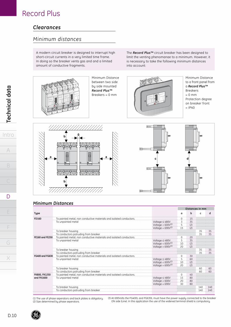
Clearances
Minimum distances
A modern circuit breaker is designed to interrupt high short-circuit currents in a very limited time frame. In doing so the breaker vents gas and and a limited amount of conductive fragments.
The Record Plus™ circuit breaker has been designed to limit the venting phenomanae to a minimum. However, it is necessary to take the following minimum distances into account:
Minimum Distance between two side by side mounted Record Plus™ Breakers = 0 mm
Minimum Distance to a front panel from a Record Plus™ Breakers = 0 mmProtection degree on breaker front = IP40
(1) The use of phase seperators and back plates is obligatory.(2) Size determined by phase seperators.
PolySafe, glass fibre reinforced polyester cabinet IP65
Distances in mm
(3) At 690Volts the FG400L and FG630L must have the power supply connected to the breaker ON side (Line). In this application the use of the widened terminal shield is compulsory.

Record Plus
D.11
Mounting in enclosures
Intro
A
B
C
D
E
F
G
X
Rotary handle type
FDNRCFENRCFENRCFENRCFENRCFGNRCFGNRC
Size
440 x 320 x 254440 x 320 x 254640 x 320 x 254440 x 320 x 254640 x 320 x 254
(2)(2)
Type
VMS43 + extension frameVMS43 + extension frameVMS63 + extension frameVMS43 + extension frameVMS63 + extension frame
(2)(2)
Ref. nr.
855085855087855088855087855088
(2)(2)
Record Plus Breaker(1)
In (A)
125A160A160A250A250A400A630A
Breaker type
FD160 with and without RCDFE160FE160 with RCDFE250FE250 with RCDFG400 or FG 630FG400 or FG630 with RCD
VMS, thermoplastic housing IP65 with opaque cover
Individual mounting of Record Plus™ in enclosures
Record Plus™ breakers can be placed in enclosures for use as individually wall mounted feeder units. In order to ensure a reliable and practical solution each of the combinations mentioned here have been defined by strenous testing. Here the properties of all components, and their use as a combination have been taken into account . For all other application of the Record Plus™ in individually mounted enclosures, please contact us.
VMS, thermoplastic box IP65 with transparent cover. The use of short or long terminal covers for the breaker is mandatory.
Breaker and terminal covers always have to be ordered separately. Short-circuit rating: 20kA, 440V
Size
440 x 320 x 254640 x 320 x 254640 x 320 x 254
FGNRCFGNRC
Ref. nr.
855085(3)
855087 / 855088(3)
855087 / 855088(3)
(2)(2)
Size
750 x 500 x 320750 x 500 x 320750 x 500 x 320
(2)(2)
Ref. nr.
883008883008883008
(2)(2)
Record Plus Breaker(1)
In (A)
125A160A250A400A630A
Breaker type
FD160 w/out RCDFE160 w/out RCDFE250 w/out RCDFG400 or FG 630FG400 or FG630 with RCD
PolySafe, glass fibre reinforced polyester cabinet IP65
PolySafe, glass fibre reinforced Polyester, cabinet IP65 with door. When using Record Plus™ Breaker in polyester cabinets for outdoor use we recommend encapsulating the
breaker in a VMS box. Breaker, terminal covers and mounting plate for the external housing have to be ordered separately.Short-circuit rating: 20kA, 440V(3)
(1) Ambient temperature max. 30 degrees centigrade. (2) Please contact us. (3)The use of short or long terminal covers on the breaker is mandatory
Housing
Internal housing VMS External housing Polysafe

Tech
nica
l dat
a
Intro
A
B
C
D
E
F
G
X
Record Plus
D.12
Electrodynamic forcesThese are proportional to the square of the crest current value.The electrodynamical forces due to the crest current value can seriously damage equipment as busbar systems and their supports, downstream switchgear etc. Current limiting devices limit the crest value of the short-circuit current and thus reduce theses forces.
Magnetic fieldsA high level short-circuit produces magnetic fields that prevent electrical equipment as meters and computers from operating correctly.
Thermal stress (heat)Thermal stress is proportional to the square of the effective current value.The thermal stress limit of cable isolation, busbar supports and other electrical equipment can be expressed as an A2S value. This electrical energy value must be kept within certain pre-defined limits to prevent overheating.To avoid or to limit the effects of these issues the use of current limiting devices is advisable.
Thermal stress in Electrical conductorsCable have thermal stress limits normaly expressed in a A2S value that depend on the cable´s cross section and its isolation. They are limited to prevent the insulation conductor from exceeding their limit temperature.Clause 434.5.2 of the IEC 60364-4-43 ed. 03 - 2008 defines that for protection devices interrupting within 0.1 seconds (t<=0.1 second) and current limiting devices as Record Plus, the following formula applies:
K2 x S2
K: factor provided in the standard; depends on the material that the conductor is made of and it's insulation
S: cross section of the conductor
If the protection device is NOT current limiting. Clause 434.5.2 of the IEC 60364-4-43 ed. 03 - 2008 applies. Here for interruption times up to 5 seconds, the regulation requires that the following formula is met .
t = (K * S/I)2
Terminologyt: Duration of the short-circuit in seconds.K: Factor provided by the standard; depending on the
material the conductor is made of and it's insulation.S: Cross Section of the conductor. I: Effective short-circuit current. (r.m.s value)
Current limitation
A short-circuit is an overcurrent with a value only limited by the impedance of the fault circuit itself. This impedance is determined by a number of factors the main ones of which are the available power that a network can supply and the impedance of the conductors within the fault circuit.
In modern hi-power electrical distribution networks very high prospective fault levels of 100kA or more can occur. High prospective short-circuit current values can cause issues in a number of areas:
Core
CuAlCuAlCuAlCuAlCu Cu
10
x106
1.3230.5781.0000.7402.0450.8841.9880.8651.8231.323
4
x104
21.1609.242
16.00011.83432.71814.13831.81013.83829.16021.160
1.5
x104
2.9761.3002.2501.6644.6011.9884.4731.9464.1012.976
16
x106
3.3861.4792.5601.8935.5322.2625.0902.2144.6663.386
6
x104
47.61020.79436.00026.62673.61631.81071.57231.13665.61047.610
2.5
x104
8.2663.6106.2504.623
12.7815.523
12.4265.406
11.3918.266
25
x106
8.2663.6106.2504.623
12.7815.523
12.4265.406
11.3918.266
35
x106
16.2017.076
12.2509.060
25.05010.82424.35410.59522.32616.201
50
x106
33.06314.44025.00018.49051.12322.09049.70321.62345.56333.063
70
x108
0.6480.2830.4900.3621.0020.4330.9740.4240.8930.648
95
x108
1.1940.5210.9030.6671.8460.7971.7940.7811.6451.194
120
x108
1.9040.8321.4401.0652.9451.2722.8631.2452.6241.904
150
x108
2.9761.3002.2501.6644.6011.9884.4731.9464.1012.976
185
x108
4.5261.9773.4232.5316.9993.0246.8042.9606.2384.526
240
x108
7.6183.3275.7604.260
11.7795.090
11.4514.982
10.4987.618
300
x108
9.5484.1626.6562.924
17.8937.784
17.8937.784
16.40311.903
Insulation
PVC - 70°
PVC - 90°
XLPE and EPR 90°
Rubber 60°
Mineral bare 105° k=135Mineral bare 105° k=115
Aluminium (Al)
766886579493-
Copper (Cu)
11510310086
143141
135 or 115(1)
Insulation and maximum temperature
PVC - 70° < 300 sq.mmPVC - 70° ≥ 300 sq.mmPVC - 90° < 300 sq.mmPVC - 90° ≥ 300 sq.mmXLPE and EPR 90°Rubber 60°Mineral, bare unsheathed 105°
K factors in accordance with the IEC 60364-4-43 ed.03
(1) The 115 value is be used for conductors exposed to touch.
Cross section in sq. mm and maximum permissible thermal stress in A2s
Crest value andwaveform withoutcurrent limitation.
Effect of a current limiting deviceon a short-circuit in an AC network.
Crest value andwaveform withoutcurrent limitation.
Maximum permissible thermal stress in conductors

Record Plus
D.13
Current limitation
Intro
A
B
C
D
E
F
G
X
Record Plus™ MCCB’s revolutionary design is equipped with dual contacts placed in a rotary configuration that enables the device to provide the highest available interruption ratings in the smallest possible size. When the breaker reacts it does so with more than twice the speed and force of conventional breakers, thus providing excellent current limitation. This results in low peak current and energy values in the circuit and leads to lower electro-dynamic forces and thermal stress values in the protected electrical conductors, downstream protection devices and equipment.
However, in some cases it is still necessary to check if the electrical conductors are protected correctly. This can be verified by taking the cable stress limits published on the previous page and comparing them with the let-through energy values found in the graphs. (page D.14 and D.15)
The limitation of electrodynamic forces and thermal stress by using back-up protectionProtection devices placed downstream from a protective device as a Record Plus™ breaker must be able to withstand the thermal and electrodynamic effects that occur at its point of installation. Placing current limiting devices upstream limits these values and can allow the use of smaller and more economical devices than is possible without the use of current limitation.
Back-up protection with Record Plus™ is described in the application data section of this catalogue. (page E.20)
H

Tech
nica
l dat
a
Intro
A
B
C
D
E
F
G
X
Record Plus
D.14
Current limitation data at 400/415V
Thermal stress (Energy) Limitation data at 400/415V

Record Plus
D.15
Current limitation
Intro
A
B
C
D
E
F
G
X
Current limitation data at 690V
Thermal stress (Energy) Limitation data at 690V

Tech
nica
l dat
a
Intro
A
B
C
D
E
F
G
X
Record Plus
D.16
Record Plus™ breakers are designed to operate normally at temperatures of -20 degrees to +70°C. Above 40°C derating factors must be applied for two basic reasons:- To prevent the materials used to construct the device from reaching temperatures that have an adverse effect on their mechanical and/or electrical properties.- When the breakers is equipped with a thermal magnetic protection device the bimetal in the device will react to the heat generated by the current flowing through the device.Typical for this kind of device is that its reaction time speeds up at higher ambient temperatures.
To achieve the same reaction time on a set current value it becomes necessary to derate.The time current curves published in this catalogue are always valid for oper-ating temperatures between 10 and 40°C.
Storage temperature
A Record Plus™ breaker is able to withstand non- operational storage temperature ranges of -40 to +85°C.
Influence of altitude
Up to altitudes of 2000 m above sea level no derating of breaker current or rated voltage is apllicable. For altitudes above 2000 m the following factors apply:
Other atmospheric conditions
The breaker is designed to operate at the tem-peratures and relative humidities defined in the EN 60947 clause 6.1.3.1. It also meets the following standards:
IEC 68-2-1IEC 68-2-2IEC 68-2-14IEC 68-2-27IEC 68-2-29IEC 68-2-30IEC 68-2-31
Shock and vibration
The Record Plus™ line has been designed to withstand shock and vibration to the following standards:IEC 68-2-6Germanischer LloydMore specifically: Record Plus™ passed the following electro-mechanical tests:
Functions normally while being subjected to 30 minutes of random vibration with a power spectral density of 0.29g2/Hz in the range of 5Hz to 500Hz (3dB corner points, ±20dB/decade rolloff ), this over three axes.(1)
Functions normally while being subjected to sinusoidal vibration of 5g Peak from 10Hz to 500Hz using 30 minute sweeps with additional 30 minutedwells at the three greatest resonance
points in this frequency range, this over three axes.
The product is shock resisitant and can withstand the following impacts in any possible orientation:20g, 6ms, 10g, 11ms (1)
Environmental considerations
Ambient temperature
ColdDry heatChange of temperatureShock testBumpDamp heat cyclicDrop
550V0.98 x In
480V0.93 x In
420V0.9 x In
Altitude (meters)
Ue max. (Volts)Max. Thermal current at 40° C
Altitude
3000m 4000m 5000m
(1) Not applicable to PremEon S trip unit

Record Plus
D.17
Environment
Intro
A
B
C
D
E
F
G
X
Electromagnetic compatibility
Meets the most stringent requirement of the EN 60947-2 and IEC 1000-4. The breaker and electronic trip unit have passed the following tests.
Harmonics, current dips, interruptions and power frequency variations.EN 60947-2 Annex F, Sub-clause F4.1 through 3 All requirements of non-sinusoidal currents resulting from harmonics are met i.e:
- Wave form consisting of a fundamental component + 3rd harmonic component at 50 and 60Hz
- Wave form consisting of a
fundamental component + a 5th harmonic component at 50 and 60Hz- Composite wave form with a fundumental
component + 3rd, 5th and 7th and a harmonic at 50 and 60Hz
- All current dips and current interruptions are met . - Frequency variation test from 45Hz to 65Hz in 1Hz
steps (required 50Hz to 60Hz in 1Hz steps)
Electrostatic dischargeEN 70947 Annex F, Sub-clause F6 and the IEC 1000-4-2Radiated, radio frequency, electromagnetic field immunity testEN 60947-2 Annex F, Sub-clause F7 and the IEC 1000-4-3Electrical fast transient/burstEN 60947-2 Annex F, Sub-clause F5 and the IEC 1000-4-4Surge immunity testEN 60947-2 Annex F, Sub-clause F5 and the IEC 1000-4-5Dry heat testEN 60947-2 Annex F, Sub-clause F8Thermal shock testEN 60947-2 Annex F, Sub-clause F9

Tech
nica
l dat
a
Intro
A
B
C
D
E
F
G
X
Record Plus
D.18
Use in DC networks
Network Type
Electrical schemes
Maximum short-circuit current (Icc max)
Minimum poles needed Breaking capacity on each pole
Center point connected to earth (A)
short-circuit A-B2 (one on each polarity)
Icc max at V/2
One pole connected to earth (B)
short-circuit A-B or A-C1 (unearthed polarity)
Icc max at V
Insulated from earth (C)(1)
short-circuit A-B2 (one on each pole)
Icc max at V
Use in DC networks
In both AC and DC networks protective devices are required to interrupt the prospective short-circuit current at the point where the device is installed. For circuit breakers as the Record Plus™ this value is called the interuption or breaking capacity (Icu or Ics), a value dependent not only on the prospective fault current value but also on the system voltage rating. For DC networks the situation is basically the same as for AC networks.
However, the system voltage generally plays a greater role (is more difficult to interrupt) while the network defines how many poles need to participate in the interruption.The drawing below indicates the three possible DC networks with the "worst" short-circuit for each of them, the number of poles that must particpate in the breaking operation and the voltage level that needs to be interrupted.
Record Plus™ FD, FE, FG and FK line breakers can be used in DC networks with standard thermal magnetic trip units.For Record Plus™ FG line breakers, please contact us. The nominal current rating of the device does not vary in AC or DC applications. The setting of the short-circuit or magnetic device needs to be multiplied by 1.2 to determine its threshold in a DC network.The table indicates the nominal current , the breaking capacity (Icu=Ics) and the number of poles needed to participate in the interruption.
Example Rated voltage 500V DC; Rated current 200A Icc max 50kA network A: center point connected to grondFE250N 3x 250 - 1pole for each polaritynetwork B: one pole connected to groundFE250N 3x 250 - 2poles on unearthed polarity.network C: insulated networkFE250N 3 x 250 - 1 pole on each polarity
(1) When a pole is grounded due to a first fault nothing happens, on a second fault the network behaves like a system with "one polarity connected to ground"
Breaker
FD160SFD160NFD160HFD160LFE160NFE160HFE160LFE250VFE250NFE250HFE250LFG400NFG400HFG400LFK800NFK800HFK800L
FK1250NFK1250NFK1250L
Rated current
16÷16016÷16016÷16016÷16025÷16025÷16025÷160
125÷250125÷250125÷250125÷250
500÷800500÷800500÷800
640÷1250640÷1250640÷1250
110V DC
25 (1p)40 (1p)65 (1p)
100 (1p)50 (1p)85 (1p)
100 (1p)25 (1p)50 (1p)85 (1p)
100 (1p)
50 (1p)60 (1p)80 (1p)50 (1p)60 (1p)80 (1p)
250V DC
25 (2p)40 (2p)65 (2p)
100 (2p)50 (2p)85 (2p)
100 (2p)25 (2p)50 (2p)85 (2p)
100 (2p)
50 (2p)60 (2p)80 (2p)50 (2p)60 (2p)80 (2p)
440V DC
25 (3p)40 (3p)65 (3p)
100 (3p)50 (3p)85 (3p)
100 (3p)25 (3p)50 (3p)85 (3p)
100 (3p)
36 (3p)60 (3p)80 (3p)36 (3p)60 (3p)80 (3p)
500V DC
- 40 (3p)65 (3p)
100 (3p)50 (3p)85 (3p)
100 (3p)-
50 (3p)85 (3p)
100 (3p)
36 (3p)60 (3p)80 (3p)36 (3p)60 (3p)80 (3p)
Thermal threshold
= AC= AC= AC= AC= AC= AC= AC= AC= AC= AC= AC
no protectionno protectionno protectionno protectionno protectionno protection
Magnetic threshold
1.21.21.21.21.21.21.21.21.21.21.2
1.21.21.21.21.21.2
Use in DC networks with standard thermal magnetic trip units