ge monogram® installation instructions microwave oven
TRANSCRIPT

GE Monogram®
Installation
Instructions
Under Cabinet Installation
and
JX827 Series Built-In Kit
Microwave Oven
Models
ZEM200 Series
Before you begin—Read these instructions completely and carefully.IMPORTANT: Save these instructions for local inspector’s use.IMPORTANT: OBSERVE ALL GOVERNING CODES AND ORDINANCES.NOTE TO INSTALLER: Be sure to leave these instructions with the Consumer.NOTE TO CONSUMER: Keep these instructions with your Use and Care Book for futurereference.
This appliance must be properly grounded. See “Electrical Supply”, page 6.CAUTIONWARNING
If you have questions concerning the installa-tion of this product, call the GE AnswerCenter® Consumer Information Service at800.626.2000, 24 hours a day, 7 days a week.If you received a damaged microwave oven,you should contact your dealer.
Proper installation is the responsibility of theinstaller. Product failure due to improperinstallation is not covered under the GEAppliance Warranty. See the Use & CareGuide for warranty information.
Contents Design Information
Model Available ................................................................................................................................... 3Dimensions and Clearances ............................................................................................................... 3Installation Options ............................................................................................................................ 3Advance Planning ............................................................................................................................... 3
Cabinetry
In-Wall Installation .............................................................................................................................. 4Installation with Single Oven ............................................................................................................. 5Under-Cabinet Mounting ................................................................................................................... 5
Installation Preparation
Electrical Supply .................................................................................................................................. 6In-Wall Installation .......................................................................................................................... 6, 7Under-Cabinet Mounting ................................................................................................................... 7
Installation
JX827 Installation ...................................................................................................................... 8, 9, 10Assemble Trim Kit Frame ................................................................................................................. 11Install Trim Kit Frame ....................................................................................................................... 11Under-Cabinet Mounting ................................................................................................................. 12To Drill from Inside .................................................................................................................... 12, 13To Drill from Bottom ........................................................................................................................ 13If Cabinet Has a Partition ................................................................................................................. 13Finalize Under-Cabinet Installation ................................................................................................. 14
2
Design Information
Micr owav e Oven
Modelavailable
Dimensionsand clearances
Installationoptions
3
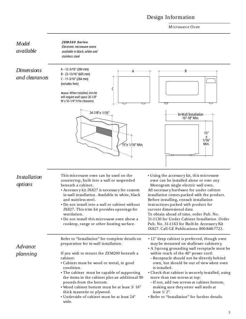
ZEM200 SeriesElectronic microwave ovensavailable in black, white andstainless steel
A - 12 -5/16" (284 mm)B - 23-13/16" (605 mm)C - 11-3/16" (284 mm)(includes feet)
Note: When installed, trim kitwill require wall space 26-1/8"W x 16-1/4" H for clearance.
This microwave oven can be used on thecountertop, built into a wall or suspendedbeneath a cabinet.• Accessory kit JX827 is necessary for custom
in-wall installation. Available in white, blackand stainless steel.
• Do not install into a wall or cabinet withoutJX827. This trim kit provides openings forventilation.
• Do not install this microwave oven above acooktop, range or other heating surface.
Advanceplanning
Refer to “Installation” for complete details onpreparation for in-wall installation.
If you wish to mount the ZEM200 beneath acabinet:• Cabinet must be wood or metal, in good
condition.• The cabinet must be capable of supporting
the items in the cabinet plus an additional 90pounds from the bottom.
• Wood cabinet bottom must be at least 3/16"thick masonite or plywood.
• Underside of cabinet must be at least 24"wide.
• 12" deep cabinet is preferred, though ovenmay be mounted on shallower cabinetry.
• A 3-prong grounding wall receptacle must bewithin reach of the 40" power cord:–Receptacle should not be directly behind
oven, but should be out of view when ovenis installed.
• Check that cabinet is securely installed, usingmore than two screws at top:–If not, add two screws at cabinet bottom,
making sure they enter wall studs atleast 1/2".
• Refer to “Installation” for further details.
C
A B
24-7/8"± 1/16"
15"± 1/16" Min.
In-Wall Installation16"-18" Min.
15"±
1/16"Min.
• Using the accessory kit, this microwaveoven can be installed alone or over anyMonogram single electric wall oven.
All necessary hardware for under cabinetinstallation comes packed with the product.Before installing, consult installationinstructions packed with product forcurrent dimensional data.To obtain ahead of time, order Pub. No.31-1130 for Under Cabinet Installation. OrderPub. No. 31-1163 for Built-In Accessory KitJX827. Call GE Publications: 800-848-7722.

Installation Preparation
Microwave Oven
Note: When installed, trimkit will require wall space26-1/8" W x 16-1/4" H forclearance.
Within opening of appropriate dimensions:• Install a level base of plywood:
–Flush with lower edge of opening.–Entirely covering floor of opening.
• 3/8" thick (min.) plywood must be sup-ported by 2" x 4" or 1" x 2" equivalentrunners on all sides.
• Finished floor must support a minimum of100 pounds.
• JX827 accessory kit may be assembled andinstalled at this time. Refer to “Installation”for instructions.
The JX827 accessory kit provides trim strips toconceal all raw edges of cabinets.
Tools and materials required:•3/8" thick plywood (min.)•2" x 4" lumber•Saw•Screws and screwdriver or other hardware for construction of
plywood base.
The opening must be:• 24-7/8" ± 1/16" wide.• 15" ± 1/16" high.• With approximately 1-1/4" for oven trim
overlap around all edges of opening.• Deep enough to accommodate electrical
receptacle and permit adequate air circula-tion for proper venting:–Minimum 18" deep with receptacle inside
cutout.–Minimum 16" deep with receptacle outside
cutout.• Height from floor may vary according to
preference of user.
18" Min.ReceptacleInside16" Min.ReceptacleOutside
15" ± 1/16
24-7/8"±1/16"
16"-18" Min.
15"±
1/16"
3/8"PlywoodBase
2 x 4 or 1 x 2Equivalent runnersmust support baseof all 4 sides
Opening
Cabinet
4
In-wallinstallation

Refer to diagram atright for dimensionswhen installing abovea Monogram singleoven.
With singleoven
Within opening of appropriate dimensions:• Install a level base of plywood:
–Flush with lower edge of opening.–Entirely covering floor of opening.
• 3/8" thick (min.) plywood must be sup-ported by 2" x 4" or 1" x 2" equivalentrunners on all four sides.
• Finished floor must support a minimum of100 pounds.
• Assemble JX827 accessory kit, refer to“Installation” for details.
Under-cabinetmounting
These microwve ovens may be installed undervirtually any cabinetry and is supplied withall hardware necessary for under-cabinetinstallation. The cabinet must be capable ofsupporting the items in the cabinet plus anadditional 90 pounds from the bottom. Referto “Advance Planning” for more details.
Note: Trim kit JX827 isrequired for installation abovea single oven.
Installation Preparation
Micr owav e Oven
5
24-7/8" ± 1/16"
Per OvenRequirement
15" ± 1/16"
Front of CabinetDoor
Bracket
Side ofMicrowave

Installation Preparation
Micr owav e Oven
Tools and materials required:•3-prong grounded electrical receptacle.•Electrical cable, 2-wire with ground, No. 14 minimum,
as required.
Monogram microwave ovens require a 120volt, 60 Hz power supply, protected by a timedelay fuse or circuit breaker.
These ovens are supplied with a power cord40" long for which a properly grounded3-prong electrical receptacle is required.• 800 watt* oven draws 1300 watts, with a
12.5 amp load.
*IEC-705 test procedureNote: Do not use an extensioncord with these appliances.
In-wallinstallation
• Install a 3-prong grounded receptacle.• Receptacle may be within opening (shaded
area in diagram):–If using this installation, be sure opening is
sufficiently deep to accommodate powercord and plug (18" min.).
• Receptacle may also be placed outsideshaded area, within reach of oven’s 40"power cord. In this case, opening need onlybe 16" deep.
Electricalsupply
6
18" Min.ReceptacleInside16" Min.ReceptacleOutside
24-7/8" ± 1/16"
15" ± 1/16"

In-wallinstallation(continued)
Under-cabinetmounting
Installation Preparation
Micr owav e Oven
• When cabinet depth is a critical factor,receptacle should be installed in a side wallat rear of opening:–14-5/8" minimum cabinet depth is
required.
Receptacle installed in sidewall.
Receptacle installed behindoven, flush with wall.
• If receptacle is located behind oven, installreceptacle flush with wall to minimize depth:–16" minimum depth is required.
Receptacle installed behindoven, extended into cabinet.
• If receptacle is located behind oven andextended into cabinet:–18" minimum cabinet depth is required.
• Do not install where vents on the sides will beblocked.
• A 3-prong grounded receptacle must bewithin reach of the oven’s 40" power cord,but located out of view when oven is installed.
• Allow access for plugging and unplugging; donot place receptacle directly behind oven.
7
14-5/8"
16"
18"

JX827installation
Installation
Micr owav e Oven
Tools and materialsrequired:•Accessory kit JX827 for
in-wall installation•2 Phillips head screwdrivers
(#1 & #2)•Drill and 3/32" drill bit•Centerpunch or nail•Pencil and ruler
JX827 Parts List1. Base Pan2. Rear Duct3. Side Covers (2)4. Top Trim5. Bottom Trim6. Side Trims7. Rear Holddown BracketsScrews A (9 required 1 extra)
B (4 required 1 extra)C (10 required 2 extra)D (4 required 1 extra)E (4 required 1 extra)
• Drive two screws into the base pan frontflange to temporarily hold in place.
• Slide two rear holddown brackets into slotsin the rear of base pan. Tongues should besticking into the base pan and centered inthe slot.
• Mark and drill four 3/32" holes.• Install both brackets with 2 screws B.• Remove two screws in the base pan front
flange and slide the base pan straight out.
• Set the base pan into cabinet cutout andcenter left and right. Front flange should bepushed back against front wall, flush withopening.
•Use the V-notch in the base pan front flangeto center.
• Drill two 3/32" diameter holes into the basesupporting structure, using the two holes inthe base pan front flange as a guide.
8
Screw A Screw B Screw EScrew DScrew C
Screw B
Screw C
Step 1Install rearholddownbrackets
1B
2
45
6
C
A
E
D
7
3 3Parts Inventory
V Notch
120V/60 HzGrounded
PowerOutlet

Step 2Installbase pan
Installation
Micr owav e Oven
Note: Do not tighten screws until all screws are started.
• Install side cover by inserting bottombetween oven and base pan.
• Start two screws A, through side cover andtwo screws E, through the cover on top intoholes where buttons were removed.
• Install other side cover with screws A.• Install other top screws E.• Tighten all screws.• Remove screw located on the top left of the
back of the oven. Retain screw.
• Remove the four top plug buttons from thetop of the microwave oven cabinet.
• Remove any protective film on oven cabinet.• Place the microwave oven on the base pan
centered left to right.
9
Screw E
Screw A
Remove 4 Plug Buttons
V Notch
Remove andSave Screw
Step 3installside covers
10
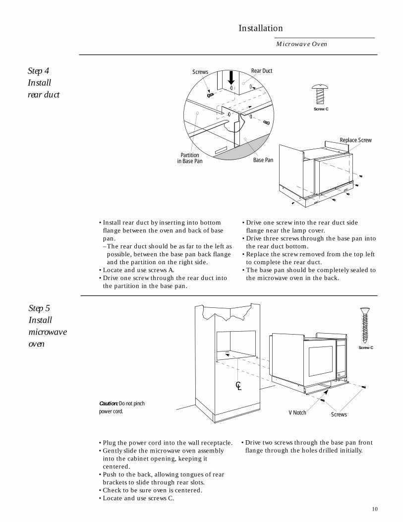
Installation
Micr owav e Oven
Step 4Installrear duct
• Install rear duct by inserting into bottomflange between the oven and back of basepan.–The rear duct should be as far to the left as
possible, between the base pan back flangeand the partition on the right side.
• Locate and use screws A.• Drive one screw through the rear duct into
the partition in the base pan.
• Drive one screw into the rear duct sideflange near the lamp cover.
• Drive three screws through the base pan intothe rear duct bottom.
• Replace the screw removed from the top leftto complete the rear duct.
• The base pan should be completely sealed tothe microwave oven in the back.
Caution: Do not pinchpower cord.
• Plug the power cord into the wall receptacle.• Gently slide the microwave oven assembly
into the cabinet opening, keeping itcentered.
• Push to the back, allowing tongues of rearbrackets to slide through rear slots.
• Check to be sure oven is centered.• Locate and use screws C.
• Drive two screws through the base pan frontflange through the holes drilled initially.
Screw C
Step 5Installmicrowaveoven
Replace Screw
Base PanPartition
in Base Pan
Rear DuctScrews
Screw C
ScrewsV Notch

11
Step 6Assembletrim kitframe
Step 7Installtrim kitframe
Installation
Micr owav e Oven
• Assemble top,bottom and sidetrims with fourscrews D, asillustrated.
When assembled,top, bottom and sidestrips must be flush.
Note: Bottom trim has a hingenotch and is notinterchangable with top trim.
Caution: Do not overtightenscrews; doing so could causemisalignment of top and sidestrips.
• Use the assembled frame as a template.Insert the frame into the cut-out and locatethe attaching holes.
• Temporarily hold the frame in place bystarting the four screws that attach the frameto the base pan and side covers.
• Push frame as far left as possible, drive thefour screws.
• Check to be sure door clears the trim whenopen.
• Mark the four holes on the side of the trim.• Remove the frame.• Center punch and drill 3/32" pilot holes.• Position the assembled frame around the
oven and secure with 8 screws C, using thesmaller Phillips head screwdriver to preventburring the Phillips head.
Screw D
Screw C
Bottom Trim
Screw Top Trim
Side Trim
Side Trim
Screw
Screw
Screw
Wall Installation
Trim Kit Frame
MarkMark
Mark
Mark

13
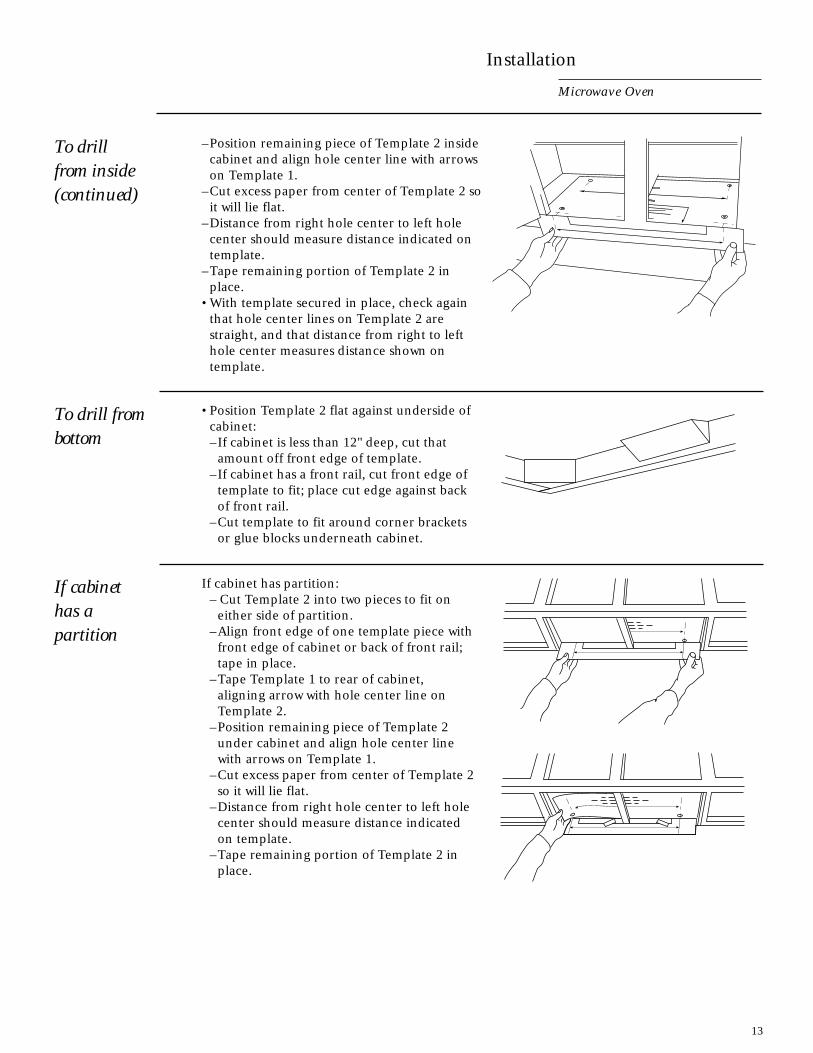
To drillfrom inside(continued)
To drill frombottom
If cabinethas apartition
–Position remaining piece of Template 2 insidecabinet and align hole center line with arrowson Template 1.
–Cut excess paper from center of Template 2 soit will lie flat.
–Distance from right hole center to left holecenter should measure distance indicated ontemplate.
–Tape remaining portion of Template 2 inplace.
• With template secured in place, check againthat hole center lines on Template 2 arestraight, and that distance from right to lefthole center measures distance shown ontemplate.
• Position Template 2 flat against underside ofcabinet:–If cabinet is less than 12" deep, cut that
amount off front edge of template.–If cabinet has a front rail, cut front edge of
template to fit; place cut edge against backof front rail.
–Cut template to fit around corner bracketsor glue blocks underneath cabinet.
If cabinet has partition:– Cut Template 2 into two pieces to fit on
either side of partition.–Align front edge of one template piece with
front edge of cabinet or back of front rail;tape in place.
–Tape Template 1 to rear of cabinet,aligning arrow with hole center line onTemplate 2.
–Position remaining piece of Template 2under cabinet and align hole center linewith arrows on Template 1.
–Cut excess paper from center of Template 2so it will lie flat.
–Distance from right hole center to left holecenter should measure distance indicatedon template.
–Tape remaining portion of Template 2 inplace.
Installation
Microwave Oven

14
Finalizeunder-cabinetinstallation
Installation
Micr owave Oven
• With template secured in place, check againthat hole center lines on Template 2 arestraight, and that distance from right to lefthole center measures distance shown ontemplate.
• Drill mounting holes:–Use of safety glasses is recommended to
protect the eyes.–Empty cabinet and remove delicate items
from adjacent cabinets.–Use center punch or nail to make an
indentation for centering the drill bit.–Holding drill straight, drill through
Template 2 at the four black drilling holesindicated on template.
–Remove template and clean drill holes.• Select four bolts—one of each size—from
parts package.• Hold each bolt against cabinet front rail.• Select bolt that extends beyond top of
bottom shelf by 3/16" to 3/4".–Correct bolt length is important. If bolt is
too short, it won’t reach oven; if bolt is toolong, oven will not be drawn up tight tocabinet.
• From inside cabinet, insert four bolts, allsame length, through mounting straps andthen into drilled holes of cabinet shelf.
• Place solid support, such as a stack of books,under oven to raise it close to cabinetbottom.
• Align mounting holes on oven with bolts.• Lift oven, and insert bolts into mounting
holes.• Tighten bolts alternately to draw oven up
evenly and secure it to cabinet bottom.• Remove oven’s rubber feet and save for
future use.• Plug power cord into receptacle.
Good AreaTop of Bottom Shelf
3/4"
3/16"
Front of CabinetDoor
Bracket
Side of Microwave

15
Notes
Microwave Ovens

NOTE: While performing installations described in this book,
safety glasses or goggles should be worn.
To obtain specific information concerning anyMonogram product or service, call GE Answer Center®
consumer information service at 800.626.2000—anytime, day or night.For Monogram local service in your area, call1-800-444-1845.
NOTE: Product improvement is a continuing endeavor at General
Electric. Therefore, materials, appearance and specifications are
subject to change without notice.
Monogram.®General Electric CompanyLouisville, KY 40225
Pub. No. 49-8893
Part No. 164D3333P128
1997 GE Appliances
(N.D. 881) 10/97