ge fanuc · pdf filethe series 90–70 plc is a member of the series 90 tm family of...
TRANSCRIPT
|__ __|__ __|
|__ __|__ __|
Î
GE Fanuc Automation
P.O. Box 8106Charlottesville, VA 22906
GFZ–0086
Î
GE Fanuc Automation
Programmable Control Products
Series 90TM–70Programmable Controller
Troubleshooting Guide

|__ __|__ __|
|__ __|__ __|
Î
GE Fanuc Automation
Programmable Control Products
Series 90TM–70Programmable ControllerTroubleshooting Guide
GFZ–0086 November1993
|__ __|__ __|
|__ __|__ __|
�����
This document is based on information available at the time of its publication. While effortshave been made to be accurate, the information contained in this document does not purportto cover all details or variations in hardware and software, nor to provide for every contingen-cy in connection with installation, operation and maintenance. This document may describefeatures not present in all hardware and software systems. GE Fanuc Automation assumes noobligation of notice to holders of this document with respect to changes subsequently made.
GE Fanuc Automation makes no representation or warranty, expressed, implied, or statutorywith respect to, and assumes no responsibility for the accuracy, completeness or usefulness ofthe information contained in this document. No warranties of merchantability of fitness forpurpose shall apply.
The following are trademarks of GE Fanuc Automation North America, Inc.
ÁÁÁÁÁÁÁ
ÁÁÁÁÁÁÁ
Alarm Master ÁÁÁÁÁÁÁÁ
ÁÁÁÁÁÁÁÁ
CIMSTAR ÁÁÁÁÁ
ÁÁÁÁÁHelpmate
ÁÁÁÁÁÁÁ
ÁÁÁÁÁÁÁ
PROMACRO ÁÁÁÁÁÁÁÁ
ÁÁÁÁÁÁÁÁ
Series Six ÁÁÁÁÁ
ÁÁÁÁÁCIMPLICITY
ÁÁÁÁÁÁÁGEnet ÁÁÁÁÁÁÁÁLogicmaster ÁÁÁÁÁSeries OneÁÁÁÁÁÁÁ
ÁÁÁÁÁÁÁ
Series 90 ÁÁÁÁÁÁÁÁ
ÁÁÁÁÁÁÁÁ
CIMPLICITY 90–ADS ÁÁÁÁÁ
ÁÁÁÁÁ
Genius
ÁÁÁÁÁÁÁ
ÁÁÁÁÁÁÁ
Modelmaster ÁÁÁÁÁÁÁÁ
ÁÁÁÁÁÁÁÁ
Series Three ÁÁÁÁÁ
ÁÁÁÁÁ
VuMaster
ÁÁÁÁÁÁÁProLoop ÁÁÁÁÁÁÁÁCIMPLICITY PowerTRAC ÁÁÁÁÁSeries FiveÁÁÁÁÁÁÁ
ÁÁÁÁÁÁÁ
Workmaster ÁÁÁÁÁÁÁÁ
ÁÁÁÁÁÁÁÁ
Genius Power TRAC ÁÁÁÁÁ
ÁÁÁÁÁ
Copyright 1993 GE Fanuc Automation North America, Inc.
All Rights Reserved.
�� ��� ��������������
������� �������� ���� ��������������
Stand clear of controlled equipment when power is applied. If the problem is intermittent,sudden unexpected machine motion could occur, causing injury. Also reference NFPA 70EPart II for additional guidelines for safety practices.
Never reach into a machine to operate a switch since unexpected motion could occur, causinginjury.
Remove all electrical power at the Main Power Disconnect to ensure total power removal.
Always remove power before inserting or removing modules, or before connecting I/O cab-ling.

|__ __|__ __|
|__ __|__ __|
������
This guide describes a logical sequence for troubleshooting your Series 90–70 program-mable controller. The Series 90–70 PLC is a member of the Series 90TM family of program-mable logic controllers from GE Fanuc Automation.
��������� �� ���� ��������������� ��� �
This is the first release of this Troubleshooting Guide. Included are models CPU models 731,732, 771, 772, 781, 782, and CPM914. CPU models 788 and 789 are also included; however,troubleshooting these models may require techniques beyond the scope of this Troubleshoot-ing Guide.
����� �����������
Series 90TM–70 Programmable Controller Installation Manual (GFK–0262).
LogicmasterTM 90–70 Programming Software User’s Manual (GFK–0263)
Series 90TM–70 Programmable Controllers ReferenceManual (GFK–0265)
Series 90TM–70 Programmable Controller Data Sheets (GFK–0600)
�� ������� ��� �������� � �����������
At GE Fanuc Automation, we strive to produce quality technical documentation. After youhave used this troubleshooting guide, please take a few moments to write us with your com-ments and suggestions. Our address is: Manager Technical Publications, GE Fanuc Automa-tion. PO Box 8106, Charlottesville, VA 22906
Drake C. Fink
Sr. Staff Systems Engineer
|__ __|__ __|
|__ __|__ __|
������ ���� � ��� �����
�����
������ ��
�
���� �� ���� �����
�� ��� ���� �����
����� ��� ���� ����
��� ����� ������ ��
��� �������� � ���
�����
������ ���� ���������� ��� �����
��� ������������ ����
� ������� ���� �
��������
� �������� �����
��� �� �� ���������
� ������� ��� ����
�� ����� ���� ��� ���
�������� ���� ���
�������� �� ��������
�� � ��������������
������� ��� �� ���
�������� ���� ������
� ������� ��� ����
�� ����� ��� � ���
��� �������� ���
����� � � �������� ��
���� ������
�����

– 1 –
�������� ������� ������ ���� ��� �
����� ���
Although your PLC CPU may be running in RUN/IO ENABLED mode, and you may havecommunications between the PLC and Logicmaster 90, the system may not be operating cor-rectly. The following pages suggest some areas to investigate:
Grounding:� Verify all power supply mounting screws are tightened.� Verify the green grounding wire provided with the power supply is securely
attached to the rack grounding stud.� Verify all racks are grounded to a common ground. Reference the System
Grounding Procedures in the Series 90–70 Programmable ControllerInstallation Manual (GFK–0262) for additional information.
Loss of Rack Fault:� Verify all inter–rack cables are securely connected on both ends. Verify cables
connect to all racks.� Verify the bottom connector on the last Bus Receiver Module has a terminator
plug. (No terminator is needed on a Bus Transmitter Module when there are noexpansion racks.)
� Verify all power supplies are powered on (Green LEDs on). Follow the sametroubleshooting procedures for expansion racks power supplies as you use for themain rack.
� Verify each expansion rack has a unique address. ONLY the rack containing theCPU is address zero. All other racks are in the range 1 to 7. NO rack is in therange 8 to 15.
� If all the above are true and you still have LOSS OF RACK, then:� Power off all racks. Remove expansion rack cable from bottom connector on the
Bus Transmitter Module (BTM) in the main rack. Power on the main rack. Youshould see LOSS OF RACK faults for all expansion racks in the PLC Fault Table.Place the PLC in RUN mode. (If you have configured the LOSS OF RACK faultto be FATAL, you will have to clear the PLC Fault Table before you can placethe PLC in RUN mode.)
� Power off all racks. Connect expansion cable to next rack, so previous rack isstill in the chain. Connect terminator plug to bottom connector on BRM. Poweron all expansion racks. Power on main rack. LOSS OF RACK faults for allnon–connected expansion racks should appear in the PLC CPU Fault Table.Place PLC in RUN mode. Replace BRM and cable if LOSS OF RACK faultpersists.
� Continue debugging the expansion rack chain one rack at a time until all rackshave been added to the chain and no LOSS OF RACK faults occur.
Other Faults:� Position the cursor on the fault. Using Release 4 Logicmaster, press the ZOOM
(F10) key. Read the fault explanation and follow the suggestions for eliminatingthe fault.
No Input:� Verify no LOSS OF MODULE fault for the module containing the input in the
I/O Fault Table. Replace the module if the LOSS OF MODULE fault is present.
� Verify no ADDITION OF MODULE fault occurs in the I/O Fault Table whenyou power cycle the PLC or store the configuration to the PLC. If so, the modulephysically resides in the slot, but is not present in the PLC configuration. Addthe module to the configuration and restore the configuration.
� Verify the %I address assigned for the input in the configuration is the same %Iaddress as used in the program.
� Verify pins in the VME bus connector are not bent or corroded.� Verify the input device functions correctly.� Verify wiring from input device through terminal strip to input module is intact.� Verify presence of power at the input device.

– 2 –
� Verify no fuses are blown.� Replace the module if other input channels on this module function.
No Output:� Verify no LOSS OF MODULE fault for the module containing the output in the
I/O Fault Table. Replace the module if the LOSS OF MODULE fault is present.� Verify no ADDITION OF MODULE fault occurs in the I/O Fault Table when
you power cycle the PLC or store the configuration to the PLC. If so, the modulephysically resides in the slot, but is not present in the PLC configuration. Addthe module to the configuration and restore the configuration.
� Verify the %Q address assigned for the output in the configuration is the same%Q address as used in the program.
� Verify pins in the VME bus connector are not bent or corroded.� Verify fuse on output module (if present) is not blown.
� Verify the output device functions correctly.� Verify wiring from output module through the terminal strip to the field device
is intact.� Verify presence of power at the output module.� Verify no fuses are blown in the path from the output module to the field device
.� Replace the module if other output channels on this module function.
Genius Devices Do Not Function:� Verify the Genius Bus Controller appears in the configuration and the
configuration in the PLC and LM90 are equal.� Verify the %I/%Q addresses assigned to the Genius device in the configuration
match those used in the ladder logic.� Follow the general debug guidelines above for No Input and No Output.� Refer to the Series 90–70 Programmable Controller Genius Bus Controller &
Genius I/O System Troubleshooting Guide for more detailed GeniusTroubleshooting.

– 3 –
� �� �� ������ ��
1. WARNING: Do not discard the lithium–manganese dioxide battery in fire. Do not at-tempt to discharge the battery. The battery may burst or burn or release hazardous mate-rials. Dispose of the battery as you would any hazardous material.
2. CAUTION: After a power fault, the system will come back on in the mode (STOP/ IOE-NABLED, STOP/IODISABLED, RUN/IOENABLED, RUN/IODISABLED) in which itwas operating before power loss, unless a fatal fault occurs during the power up process.
3. Supply (input) voltage tolerances for Series 90–70 power supplies:
IC697PWR710 & 711: 93 to 132 VAC, fornominal 115 VAC input;180 to 264 VAC, fornominal 230 VAC input;47 to 63 HZ
IC697PWR722 21.6 to 26.4 VDC for24VDC nominal input
IC697PWR732 122.5 to 137.5 VDC for125VDC nominal input
4. Total cable length must not exceed 50 feet between the CPU rack (rack 0) and the lastexpansion rack. No termination plug is needed on a Bus Transmitter Module in a one–rack system.
ÁÁÁÁÁ
ÁÁÁÁÁ
ÁÁÁÁÁ
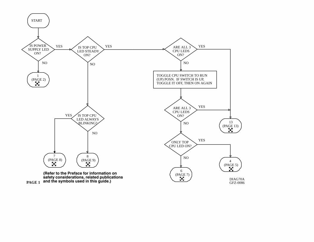
START
ÁÁÁÁÁÁÁ
ÁÁÁÁÁÁÁ
ÁÁÁÁÁÁÁ
ÁÁÁÁÁÁÁ
ÁÁÁÁÁÁÁ
ARE ALL 3CPU LEDS
ON?
ÁÁÁÁÁÁÁ
ÁÁÁÁÁÁÁ
ÁÁÁÁÁÁÁ
ÁÁÁÁÁÁÁ
ÁÁÁÁÁÁÁ
ONLY TOPCPU LED ON?ÁÁÁÁÁÁÁÁÁÁ
ÁÁÁÁÁÁÁÁÁÁ
ÁÁÁÁÁÁÁÁÁÁ
ÁÁÁÁÁÁÁÁÁÁ
TOGGLE CPU SWITCH TO RUN(UP) POSN. IF SWITCH IS UP,TOGGLE IT OFF, THEN ON AGAIN
ÁÁÁÁÁÁÁ
ÁÁÁÁÁÁÁ
ÁÁÁÁÁÁÁ
ÁÁÁÁÁÁÁ
ÁÁÁÁÁÁÁ
ARE ALL 3CPU LEDS
ON?
ÁÁÁÁÁ
ÁÁÁÁÁ
ÁÁÁÁÁ
ÁÁÁÁÁ
1(PAGE 2)
ÁÁÁÁÁÁ
ÁÁÁÁÁÁ
ÁÁÁÁÁÁ
ÁÁÁÁÁÁ
ÁÁÁÁÁÁIS POWER
SUPPLY LEDON?
ÁÁÁÁ
ÁÁÁÁ
ÁÁÁÁ
7(PAGE 8)
ÁÁÁÁÁ
ÁÁÁÁÁ
ÁÁÁÁÁ
8(PAGE 9)
ÁÁÁÁÁ
ÁÁÁÁÁ
ÁÁÁÁÁ
13(PAGE 13)
ÁÁÁÁÁ
ÁÁÁÁÁ
ÁÁÁÁÁ
ÁÁÁÁÁ
4(PAGE 5)
ÁÁÁÁÁ
ÁÁÁÁÁ
ÁÁÁÁÁ
ÁÁÁÁÁ
6(PAGE 7)
PAGE 1
Á
Á
Á
ÁÁÁÁ
Á
ÁÁ
Á
Á Á
DIAG70AGFZ-0086
NO
YESYES
NO NO
YES
YES
NO
NO
YES
NO
YES
ÁÁÁÁÁÁÁ
ÁÁÁÁÁÁÁ
ÁÁÁÁÁÁÁ
ÁÁÁÁÁÁÁ
ÁÁÁÁÁÁÁ
IS TOP CPULED STEADY
ON?
ÁÁÁÁÁÁÁ
ÁÁÁÁÁÁÁ
ÁÁÁÁÁÁÁ
ÁÁÁÁÁÁÁ
ÁÁÁÁÁÁÁ
IS TOP CPULED ALWAYSBLINKING?
ÁÁ
ÁÁ
Á
��� �� �� ��� ��� �� �� �� �������� ���� ��� �������������� ������� ������������� ��� ������ ���� �� ���� �������
ÁÁÁÁÁ
ÁÁÁÁÁ
ÁÁÁÁÁ
1
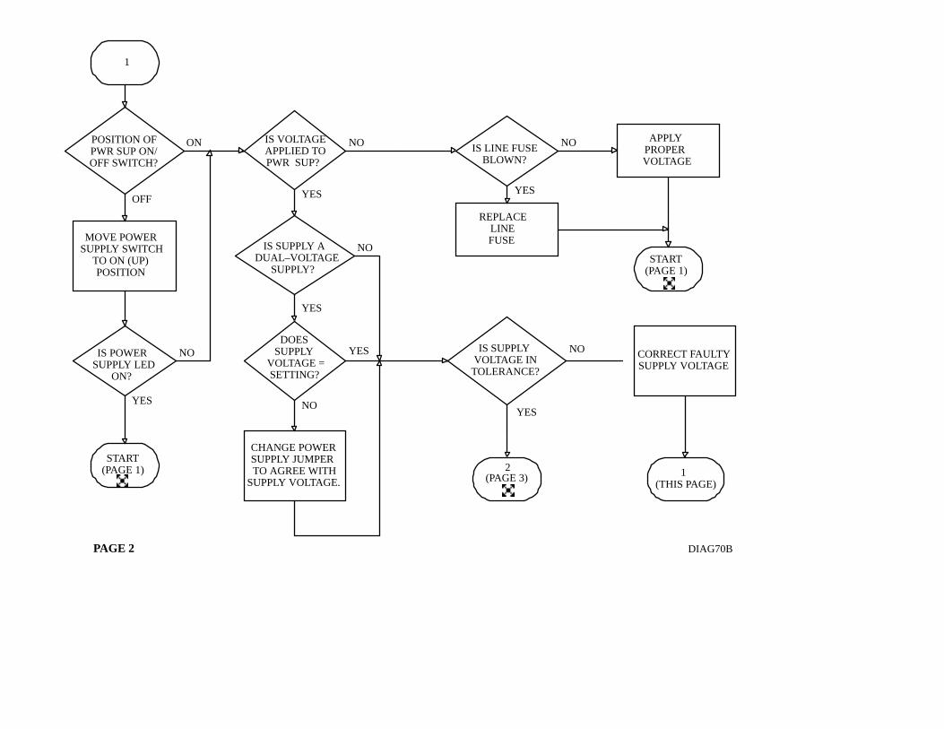
PAGE 2 DIAG70B
ÁÁÁÁÁÁÁÁ
ÁÁÁÁÁÁÁÁ
ÁÁÁÁÁÁÁÁ
ÁÁÁÁÁÁÁÁ
ÁÁÁÁÁÁÁÁ
ÁÁÁÁÁÁÁÁ
POSITION OFPWR SUP ON/OFF SWITCH?
ÁÁÁÁÁÁÁ
ÁÁÁÁÁÁÁ
ÁÁÁÁÁÁÁ
ÁÁÁÁÁÁÁ
MOVE POWERSUPPLY SWITCH
TO ON (UP)POSITION
ÁÁÁÁÁÁÁ
ÁÁÁÁÁÁÁ
ÁÁÁÁÁÁÁ
ÁÁÁÁÁÁÁ
ÁÁÁÁÁÁÁ
IS POWERSUPPLY LED
ON?
ÁÁÁÁÁ
ÁÁÁÁÁ
ÁÁÁÁÁ
START(PAGE 1)
ÁÁÁÁÁÁ
ÁÁÁÁÁÁ
ÁÁÁÁÁÁ
ÁÁÁÁÁÁ
ÁÁÁÁÁÁ
CHANGE POWERSUPPLY JUMPERTO AGREE WITH
SUPPLY VOLTAGE.
ÁÁÁÁÁÁÁ
ÁÁÁÁÁÁÁ
ÁÁÁÁÁÁÁ
ÁÁÁÁÁÁÁ
REPLACELINEFUSE
ÁÁÁÁÁÁÁ
ÁÁÁÁÁÁÁ
ÁÁÁÁÁÁÁ
ÁÁÁÁÁÁÁ
APPLYPROPERVOLTAGE
ÁÁÁÁÁ
ÁÁÁÁÁ
ÁÁÁÁÁ
START(PAGE 1)
ÁÁ
ÁÁ
ÁÁ
ÁÁ
ÁÁÁÁÁÁ
ÁÁÁÁÁ
ÁÁÁÁÁ
2(PAGE 3)
Á
ÁÁ
ÁÁ
ÁÁ
ÁÁ
Á
Á
ON
OFF
Á
NO
ÁÁÁÁÁÁ
ÁÁÁÁÁÁ
ÁÁÁÁÁÁ
ÁÁÁÁÁÁ
ÁÁÁÁÁÁ
IS VOLTAGEAPPLIED TOPWR SUP?
ÁÁ
YES
ÁÁÁÁÁÁÁÁ
ÁÁÁÁÁÁÁÁ
ÁÁÁÁÁÁÁÁ
ÁÁÁÁÁÁÁÁ
ÁÁÁÁÁÁÁÁ
ÁÁÁÁÁÁÁÁ
IS SUPPLY ADUAL–VOLTAGE
SUPPLY?ÁÁ
NO
YES
ÁÁÁÁÁÁ
ÁÁÁÁÁÁ
ÁÁÁÁÁÁ
ÁÁÁÁÁÁ
ÁÁÁÁÁÁDOES
SUPPLYVOLTAGE =SETTING?
YES
NO
Á
NO
YES
ÁÁÁÁÁÁÁ
ÁÁÁÁÁÁÁ
ÁÁÁÁÁÁÁ
ÁÁÁÁÁÁÁ
ÁÁÁÁÁÁÁ
CORRECT FAULTYSUPPLY VOLTAGE
ÁÁÁÁÁ
ÁÁÁÁÁ
ÁÁÁÁÁ
1(THIS PAGE)
ÁÁ
ÁÁÁÁÁÁÁ
ÁÁÁÁÁÁÁ
ÁÁÁÁÁÁÁ
ÁÁÁÁÁÁÁ
ÁÁÁÁÁÁÁ
IS LINE FUSEBLOWN?
NO
YES
ÁÁÁÁÁÁÁ
ÁÁÁÁÁÁÁ
ÁÁÁÁÁÁÁ
ÁÁÁÁÁÁÁ
ÁÁÁÁÁÁÁ
ÁÁÁÁÁÁÁ
IS SUPPLYVOLTAGE INTOLERANCE?
NO
YES
ÁÁÁÁÁÁÁ
ÁÁÁÁÁÁÁ
ÁÁÁÁÁÁÁ
ÁÁÁÁÁÁÁ
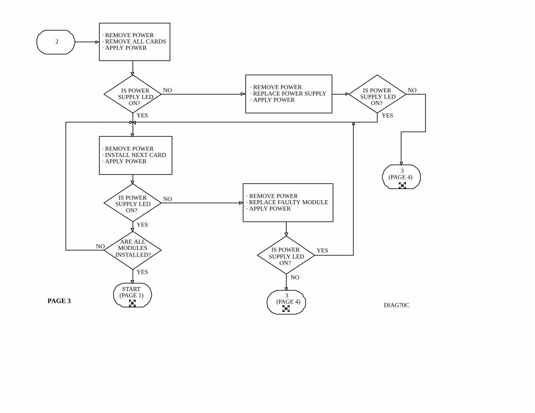
· REMOVE POWER· REMOVE ALL CARDS· APPLY POWER
ÁÁÁÁÁ
ÁÁÁÁÁ
ÁÁÁÁÁ
ÁÁÁÁÁ
2
ÁÁÁÁÁÁÁ
ÁÁÁÁÁÁÁ
ÁÁÁÁÁÁÁ
ÁÁÁÁÁÁÁ
ÁÁÁÁÁÁÁ
IS POWERSUPPLY LED
ON?
ÁÁÁÁÁÁÁÁÁ
ÁÁÁÁÁÁÁÁÁ
ÁÁÁÁÁÁÁÁÁ
ÁÁÁÁÁÁÁÁÁ
ÁÁÁÁÁÁÁÁÁ
· REMOVE POWER· REPLACE POWER SUPPLY· APPLY POWER
ÁÁÁÁÁÁÁ
ÁÁÁÁÁÁÁ
ÁÁÁÁÁÁÁ
ÁÁÁÁÁÁÁ
ÁÁÁÁÁÁÁ
IS POWERSUPPLY LED
ON?
ÁÁÁÁÁÁÁ
ÁÁÁÁÁÁÁ
ÁÁÁÁÁÁÁ
ÁÁÁÁÁÁÁ
ÁÁÁÁÁÁÁ
ARE ALLMODULES
INSTALLED?
ÁÁÁÁÁ
ÁÁÁÁÁ
ÁÁÁÁÁ
START(PAGE 1)
ÁÁÁÁÁÁÁ
ÁÁÁÁÁÁÁ
ÁÁÁÁÁÁÁ
ÁÁÁÁÁÁÁ
ÁÁÁÁÁÁÁ
IS POWERSUPPLY LED
ON?ÁÁÁÁÁ
ÁÁÁÁÁ
ÁÁÁÁÁ3
(PAGE 4)
ÁÁÁÁÁ
ÁÁÁÁÁ
ÁÁÁÁÁ
ÁÁÁÁÁ
3(PAGE 4)
PAGE 3DIAG70C
ÁÁÁÁÁÁÁ
ÁÁÁÁÁÁÁ
ÁÁÁÁÁÁÁ
ÁÁÁÁÁÁÁ· REMOVE POWER· INSTALL NEXT CARD· APPLY POWER
ÁÁÁÁÁÁÁÁÁ
ÁÁÁÁÁÁÁÁÁ
ÁÁÁÁÁÁÁÁÁ
ÁÁÁÁÁÁÁÁÁ
ÁÁÁÁÁÁÁÁÁ
· REMOVE POWER· REPLACE FAULTY MODULE· APPLY POWER
ÁÁ
ÁÁÁÁ
Á
ÁÁ
ÁÁ
Á
ÁÁÁÁ
Á
Á
ÁÁ
Á
ÁÁ
Á
NO
YES
NO
YES
NO
YESNO
YES
ÁÁÁÁÁÁÁ
ÁÁÁÁÁÁÁ
ÁÁÁÁÁÁÁ
ÁÁÁÁÁÁÁ
ÁÁÁÁÁÁÁ
IS POWERSUPPLY LED
ON?
YES
NO
ÁÁÁÁÁÁÁÁÁ
ÁÁÁÁÁÁÁÁÁ
ÁÁÁÁÁÁÁÁÁ
· REMOVE POWER· REPLACE POWER SUPPLY
ÁÁÁÁÁ
ÁÁÁÁÁ
ÁÁÁÁÁ
3
YES
NO
ÁÁÁÁÁ
ÁÁÁÁÁ
ÁÁÁÁÁ
ÁÁÁÁÁ
START(PAGE 1)
PAGE 4 DIAG70D
Á Á
ÁÁÁÁÁÁÁÁÁÁÁÁ
ÁÁÁÁÁÁÁÁÁÁÁÁ
ÁÁÁÁÁÁÁÁÁÁÁÁ
ÁÁÁÁÁÁÁÁÁÁÁÁ
ÁÁÁÁÁÁÁÁÁÁÁÁ
ÁÁÁÁÁÁÁÁÁÁÁÁ
ÁÁÁÁÁÁÁÁÁÁÁÁ
ÁÁÁÁÁÁÁÁÁÁÁÁ
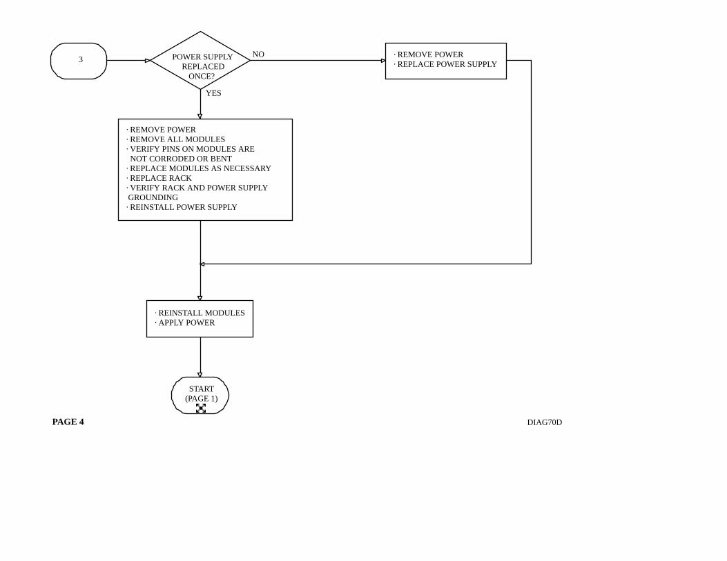
· REMOVE POWER· REMOVE ALL MODULES· VERIFY PINS ON MODULES ARE NOT CORRODED OR BENT· REPLACE MODULES AS NECESSARY· REPLACE RACK· VERIFY RACK AND POWER SUPPLY GROUNDING· REINSTALL POWER SUPPLY
ÁÁ
ÁÁ
ÁÁÁÁÁÁÁÁ
ÁÁÁÁÁÁÁÁ
ÁÁÁÁÁÁÁÁ
ÁÁÁÁÁÁÁÁ
ÁÁÁÁÁÁÁÁ
POWER SUPPLYREPLACED
ONCE?
ÁÁÁÁÁÁÁÁ
ÁÁÁÁÁÁÁÁ
ÁÁÁÁÁÁÁÁ
ÁÁÁÁÁÁÁÁ
· REINSTALL MODULES· APPLY POWER
Á
ÁÁÁÁÁ
ÁÁÁÁÁ
ÁÁÁÁÁ
ÁÁÁÁÁ
7(PAGE 8)
ÁÁÁÁÁÁÁ
ÁÁÁÁÁÁÁ
ÁÁÁÁÁÁÁ
ÁÁÁÁÁÁÁ
ÁÁÁÁÁÁÁ
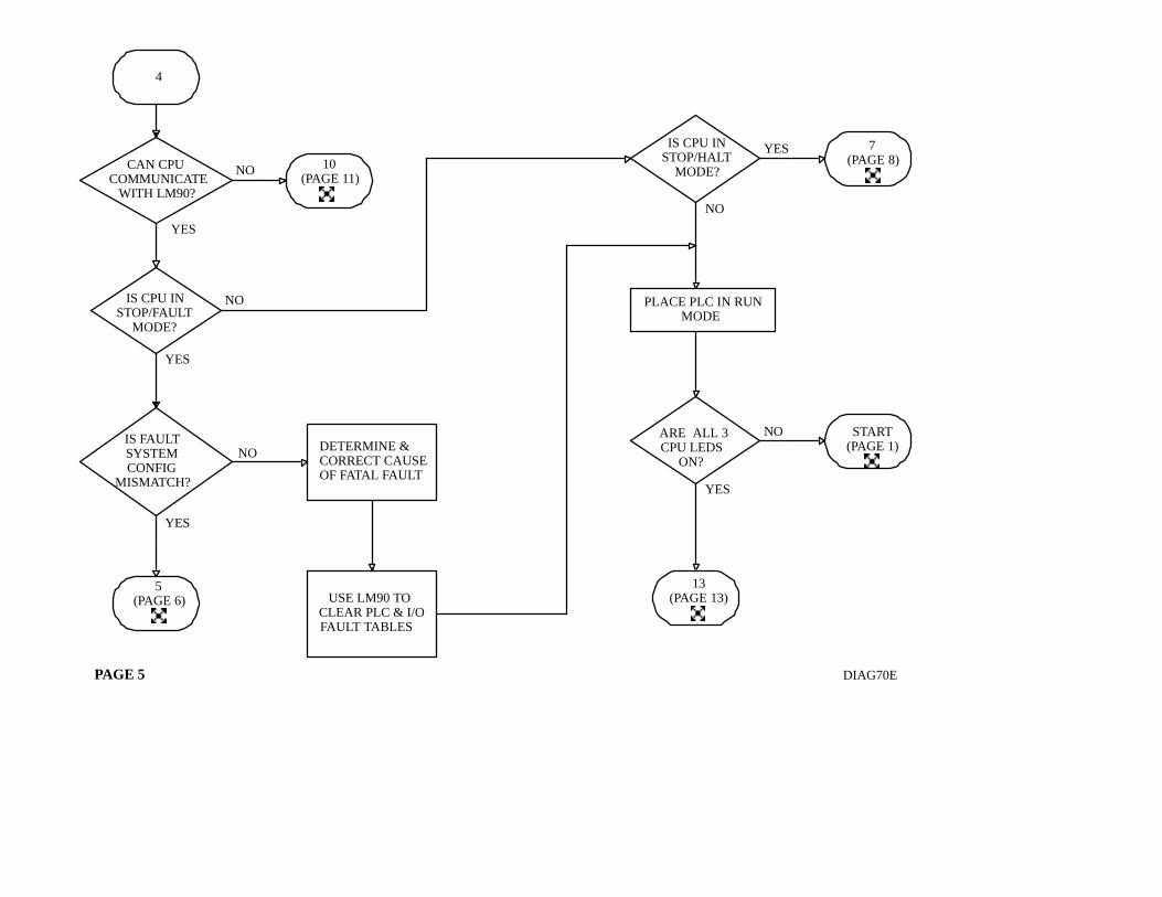
IS CPU INSTOP/FAULT
MODE?
ÁÁÁÁÁÁÁÁ
ÁÁÁÁÁÁÁÁ
ÁÁÁÁÁÁÁÁ
ÁÁÁÁÁÁÁÁ
ÁÁÁÁÁÁÁÁ
ÁÁÁÁÁÁÁÁ
IS FAULTSYSTEMCONFIG
MISMATCH?
ÁÁÁÁÁÁÁ
ÁÁÁÁÁÁÁ
ÁÁÁÁÁÁÁ
ÁÁÁÁÁÁÁ
ÁÁÁÁÁÁÁ
IS CPU INSTOP/HALT
MODE?
ÁÁÁÁ
ÁÁÁÁ
ÁÁÁÁ
ÁÁÁÁ
5(PAGE 6)
PAGE 5
ÁÁÁÁÁÁÁ
ÁÁÁÁÁÁÁ
ÁÁÁÁÁÁÁ
ÁÁÁÁÁÁÁ
ÁÁÁÁÁÁÁDETERMINE &CORRECT CAUSEOF FATAL FAULT
ÁÁÁÁÁÁÁ
ÁÁÁÁÁÁÁ
ÁÁÁÁÁÁÁ
ÁÁÁÁÁÁÁ
ÁÁÁÁÁÁÁ
USE LM90 TOCLEAR PLC & I/OFAULT TABLES
ÁÁÁÁ
ÁÁÁÁ
Á
ÁÁÁÁÁÁÁ
ÁÁÁÁÁÁÁ
ÁÁÁÁÁÁÁ
PLACE PLC IN RUNMODE
Á
ÁÁÁÁÁÁÁ
ÁÁÁÁÁÁÁ
ÁÁÁÁÁÁÁ
ÁÁÁÁÁÁÁ
ÁÁÁÁÁÁÁ
ARE ALL 3CPU LEDS
ON?
ÁÁ
ÁÁÁ
ÁÁ
ÁÁ
ÁÁÁÁÁ
ÁÁÁÁÁ
ÁÁÁÁÁ
START(PAGE 1)
NO
YES
NO
YES
NO
YES
YES
NO
ÁÁÁÁÁÁÁÁ
ÁÁÁÁÁÁÁÁ
ÁÁÁÁÁÁÁÁ
ÁÁÁÁÁÁÁÁ
ÁÁÁÁÁÁÁÁ
CAN CPUCOMMUNICATE
WITH LM90?
ÁÁÁÁ
ÁÁÁÁ
ÁÁÁÁ
4
ÁÁÁÁÁ
ÁÁÁÁÁ
ÁÁÁÁÁ
ÁÁÁÁÁ
10(PAGE 11)
Á
ÁÁÁÁ
YES
NO
DIAG70E
ÁÁÁÁÁ
ÁÁÁÁÁ
ÁÁÁÁÁ
13(PAGE 13)
ÁÁÁÁÁ
ÁÁÁÁÁ
ÁÁÁÁÁ
ÁÁÁÁÁ
5
ÁÁÁÁÁ
ÁÁÁÁÁ
ÁÁÁÁÁ
START(PAGE 1)
PAGE 6 DIAG70F
ÁÁÁÁÁÁÁÁÁÁÁ
ÁÁÁÁÁÁÁÁÁÁÁ
ÁÁÁÁÁÁÁÁÁÁÁ
ÁÁÁÁÁÁÁÁÁÁÁ
ÁÁÁÁÁÁÁÁÁÁÁ
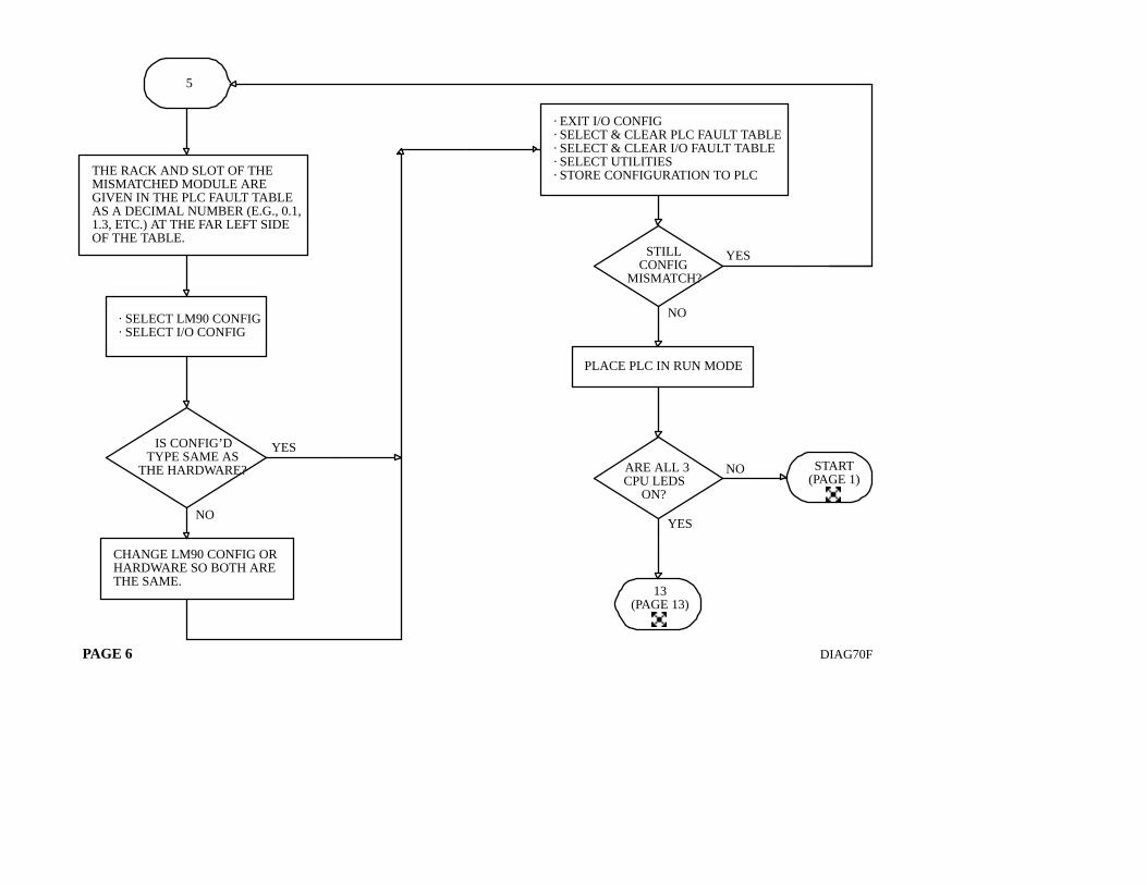
THE RACK AND SLOT OF THEMISMATCHED MODULE AREGIVEN IN THE PLC FAULT TABLEAS A DECIMAL NUMBER (E.G., 0.1,1.3, ETC.) AT THE FAR LEFT SIDEOF THE TABLE.
ÁÁÁÁÁÁÁÁ
ÁÁÁÁÁÁÁÁ
ÁÁÁÁÁÁÁÁ
ÁÁÁÁÁÁÁÁ
· SELECT LM90 CONFIG· SELECT I/O CONFIG
ÁÁÁÁÁÁÁÁÁ
ÁÁÁÁÁÁÁÁÁ
ÁÁÁÁÁÁÁÁÁ
ÁÁÁÁÁÁÁÁÁ
CHANGE LM90 CONFIG ORHARDWARE SO BOTH ARETHE SAME.
ÁÁÁÁÁÁÁÁÁÁÁ
ÁÁÁÁÁÁÁÁÁÁÁ
ÁÁÁÁÁÁÁÁÁÁÁ
ÁÁÁÁÁÁÁÁÁÁÁ
ÁÁÁÁÁÁÁÁÁÁÁ
· EXIT I/O CONFIG· SELECT & CLEAR PLC FAULT TABLE· SELECT & CLEAR I/O FAULT TABLE· SELECT UTILITIES· STORE CONFIGURATION TO PLC
ÁÁÁÁÁÁÁ
ÁÁÁÁÁÁÁ
ÁÁÁÁÁÁÁ
ÁÁÁÁÁÁÁ
STILLCONFIG
MISMATCH?
ÁÁÁÁÁÁÁÁÁ
ÁÁÁÁÁÁÁÁÁ
ÁÁÁÁÁÁÁÁÁ
PLACE PLC IN RUN MODE
ÁÁÁÁÁ
ÁÁÁÁÁ
ÁÁÁÁÁ
13(PAGE 13)
ÁÁÁÁÁÁÁ
ÁÁÁÁÁÁÁ
ÁÁÁÁÁÁÁ
ÁÁÁÁÁÁÁ
ÁÁÁÁÁÁÁ
ARE ALL 3CPU LEDS
ON?
YES
NO
NO
YES
Á
ÁÁ
ÁÁ
Á
Á
ÁÁ
Á
ÁÁÁÁÁÁÁÁ
ÁÁÁÁÁÁÁÁ
ÁÁÁÁÁÁÁÁ
ÁÁÁÁÁÁÁÁ
ÁÁÁÁÁÁÁÁ
IS CONFIG’DTYPE SAME AS
THE HARDWARE?
NO
YES
ÁÁ
ÁÁÁÁ
ÁÁ
ÁÁ
DIAG70G
ÁÁÁÁÁ
ÁÁÁÁÁ
ÁÁÁÁÁ
ÁÁÁÁÁ
6
PAGE 7
ÁÁÁÁÁÁÁ
ÁÁÁÁÁÁÁ
ÁÁÁÁÁÁÁ
ÁÁÁÁÁÁÁ
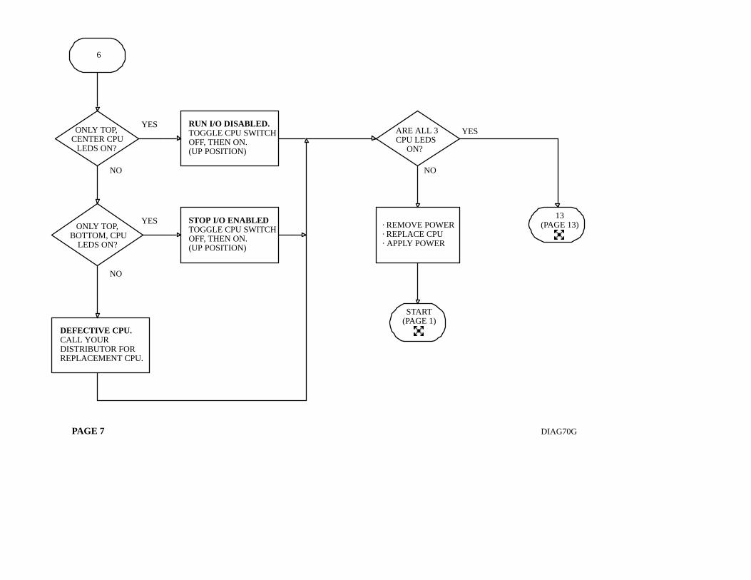
ÁÁÁÁÁÁÁONLY TOP,
CENTER CPULEDS ON?
ÁÁÁÁÁÁÁ
ÁÁÁÁÁÁÁ
ÁÁÁÁÁÁÁ
ÁÁÁÁÁÁÁ
ÁÁÁÁÁÁÁ
ONLY TOP,BOTTOM, CPU
LEDS ON?
ÁÁÁÁÁÁÁ
ÁÁÁÁÁÁÁ
ÁÁÁÁÁÁÁ
ÁÁÁÁÁÁÁ
ÁÁÁÁÁÁÁ
DEFECTIVE CPU.CALL YOURDISTRIBUTOR FORREPLACEMENT CPU.
ÁÁÁÁÁÁÁÁ
ÁÁÁÁÁÁÁÁ
ÁÁÁÁÁÁÁÁ
ÁÁÁÁÁÁÁÁ
ÁÁÁÁÁÁÁÁ
RUN I/O DISABLED.TOGGLE CPU SWITCHOFF, THEN ON.(UP POSITION)
ÁÁÁÁÁÁÁÁ
ÁÁÁÁÁÁÁÁ
ÁÁÁÁÁÁÁÁ
ÁÁÁÁÁÁÁÁ
ÁÁÁÁÁÁÁÁ
STOP I/O ENABLED.TOGGLE CPU SWITCHOFF, THEN ON.(UP POSITION)
ÁÁÁÁÁ
ÁÁÁÁÁ
ÁÁÁÁÁ
13(PAGE 13)
ÁÁÁÁÁÁÁ
ÁÁÁÁÁÁÁ
ÁÁÁÁÁÁÁ
ÁÁÁÁÁÁÁ
ÁÁÁÁÁÁÁ
· REMOVE POWER· REPLACE CPU· APPLY POWER
ÁÁÁÁÁ
ÁÁÁÁÁ
ÁÁÁÁÁ
ÁÁÁÁÁ
START(PAGE 1)
ÁÁÁÁÁÁÁ
ÁÁÁÁÁÁÁ
ÁÁÁÁÁÁÁ
ÁÁÁÁÁÁÁ
ÁÁÁÁÁÁÁ
ARE ALL 3CPU LEDS
ON?
Á
Á
ÁÁ
ÁÁ
ÁÁ
ÁÁÁ
YES
NO
YES
NO
YES
NO
ÁÁ
ÁÁÁÁÁÁ
ÁÁÁÁÁÁ
ÁÁÁÁÁÁ
ÁÁÁÁÁÁ
ÁÁÁÁÁÁ
· REMOVE POWER· REPLACE CPU· APPLY POWER
ÁÁÁÁ
ÁÁÁÁ
ÁÁÁÁ
START(PAGE 1)
ÁÁÁÁ
DIAG70HPAGE 8
ÁÁÁÁÁ
ÁÁÁÁÁ
ÁÁÁÁÁ
4(PAGE 5)
ÁÁÁÁÁ
ÁÁÁÁÁ
ÁÁÁÁÁ
ÁÁÁÁÁ
7
ÁÁÁÁÁÁÁÁ
ÁÁÁÁÁÁÁÁ
ÁÁÁÁÁÁÁÁ
ÁÁÁÁÁÁÁÁ
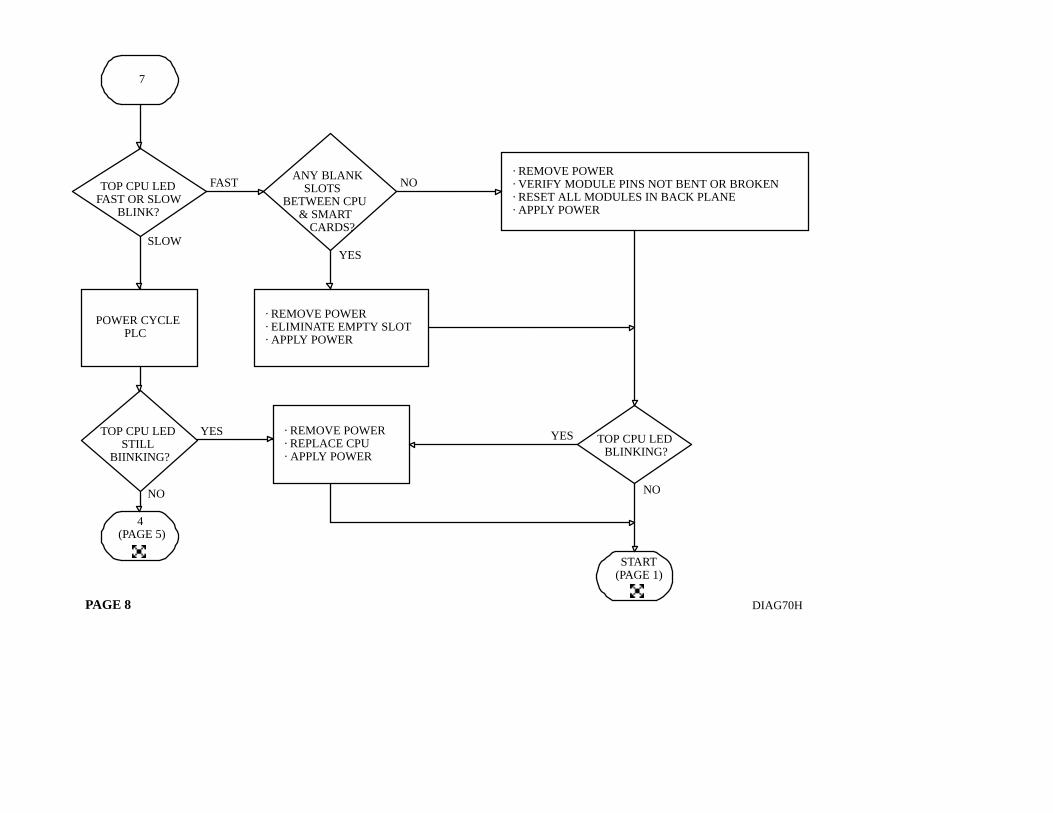
ÁÁÁÁÁÁÁÁTOP CPU LED
FAST OR SLOWBLINK?
Á
NO
ÁÁÁÁÁÁÁ
ÁÁÁÁÁÁÁ
ÁÁÁÁÁÁÁ
ÁÁÁÁÁÁÁ
ÁÁÁÁÁÁÁ
POWER CYCLEPLC
ÁÁÁÁÁÁÁ
ÁÁÁÁÁÁÁ
ÁÁÁÁÁÁÁ
ÁÁÁÁÁÁÁ
ÁÁÁÁÁÁÁ
TOP CPU LEDSTILL
BIINKING?
ÁÁÁÁÁÁÁÁ
ÁÁÁÁÁÁÁÁ
ÁÁÁÁÁÁÁÁ
ÁÁÁÁÁÁÁÁ
ÁÁÁÁÁÁÁÁ
ÁÁÁÁÁÁÁÁ
ÁÁÁÁÁÁÁÁ
ANY BLANKSLOTS
BETWEEN CPU& SMART
CARDS?
NO
YES
ÁÁÁÁÁÁÁÁÁÁÁÁÁÁ
ÁÁÁÁÁÁÁÁÁÁÁÁÁÁ
ÁÁÁÁÁÁÁÁÁÁÁÁÁÁ
ÁÁÁÁÁÁÁÁÁÁÁÁÁÁ
ÁÁÁÁÁÁÁÁÁÁÁÁÁÁ
· REMOVE POWER· VERIFY MODULE PINS NOT BENT OR BROKEN· RESET ALL MODULES IN BACK PLANE· APPLY POWER
Á
ÁÁÁÁÁÁÁÁ
ÁÁÁÁÁÁÁÁ
ÁÁÁÁÁÁÁÁ
ÁÁÁÁÁÁÁÁ
ÁÁÁÁÁÁÁÁ
· REMOVE POWER· ELIMINATE EMPTY SLOT· APPLY POWER
YES YES
ÁÁÁÁÁÁ
ÁÁÁÁÁÁ
ÁÁÁÁÁÁ
ÁÁÁÁÁÁ
ÁÁÁÁÁÁ
TOP CPU LEDBLINKING?
NO
ÁÁÁÁ
ÁÁÁÁ
ÁÁ
ÁÁ
ÁÁ
Á ÁÁ
ÁÁ
Á
FAST
SLOW
ÁÁÁÁÁÁÁÁÁ
ÁÁÁÁÁÁÁÁÁ
ÁÁÁÁÁÁÁÁÁ
ÁÁÁÁÁÁÁÁÁ
ÁÁÁÁÁÁÁÁÁ
ÁÁÁÁÁÁÁÁÁ
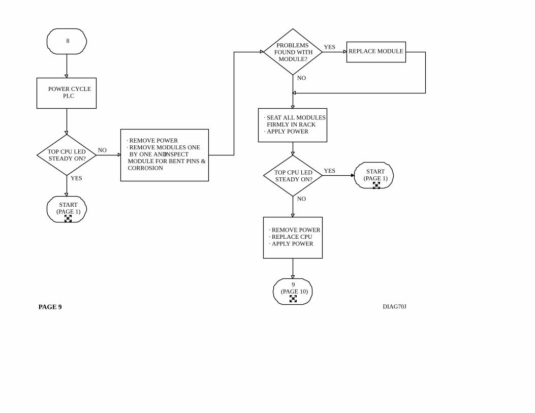
· REMOVE POWER· REMOVE MODULES ONE BY ONE ANDINSPECT MODULE FOR BENT PINS & CORROSION
ÁÁÁÁ
ÁÁÁÁ
ÁÁÁÁ
ÁÁÁÁ
START(PAGE 1)
DIAG70JPAGE 9
ÁÁÁÁÁ
ÁÁÁÁÁ
ÁÁÁÁÁ
ÁÁÁÁÁ
8
ÁÁÁÁÁÁÁ
ÁÁÁÁÁÁÁ
ÁÁÁÁÁÁÁ
ÁÁÁÁÁÁÁPOWER CYCLE
PLC
ÁÁÁÁÁ
ÁÁÁÁÁ
ÁÁÁÁÁ
ÁÁÁÁÁ
9(PAGE 10)
ÁÁÁÁÁ
ÁÁÁÁÁ
ÁÁÁÁÁ
ÁÁÁÁÁ
START(PAGE 1)
NO
ÁÁÁÁÁÁÁ
ÁÁÁÁÁÁÁ
ÁÁÁÁÁÁÁ
ÁÁÁÁÁÁÁ
ÁÁÁÁÁÁÁ
TOP CPU LEDSTEADY ON?
YES
ÁÁÁÁÁÁÁ
ÁÁÁÁÁÁÁ
ÁÁÁÁÁÁÁ
REPLACE MODULEYES
ÁÁÁÁÁÁÁ
ÁÁÁÁÁÁÁ
ÁÁÁÁÁÁÁ
ÁÁÁÁÁÁÁ
ÁÁÁÁÁÁÁ
ÁÁÁÁÁÁÁ
PROBLEMSFOUND WITH
MODULE?
NO
ÁÁÁÁÁÁÁÁ
ÁÁÁÁÁÁÁÁ
ÁÁÁÁÁÁÁÁ
ÁÁÁÁÁÁÁÁ
· SEAT ALL MODULES FIRMLY IN RACK· APPLY POWER
YES
ÁÁÁÁÁÁÁ
ÁÁÁÁÁÁÁ
ÁÁÁÁÁÁÁ
ÁÁÁÁÁÁÁ
ÁÁÁÁÁÁÁ
ÁÁÁÁÁÁÁ
TOP CPU LEDSTEADY ON?
NO
ÁÁÁÁÁÁÁ
ÁÁÁÁÁÁÁ
ÁÁÁÁÁÁÁ
ÁÁÁÁÁÁÁ
ÁÁÁÁÁÁÁ
· REMOVE POWER· REPLACE CPU· APPLY POWER
ÁÁÁÁ
ÁÁ
ÁÁ
ÁÁ
ÁÁ
ÁÁ
ÁÁ
Á
ÁÁ
ÁÁ
ÁÁ
ÁÁÁÁÁ
ÁÁÁÁÁ
ÁÁÁÁÁ
ÁÁÁÁÁ
START(PAGE 1)
DIAG70KPAGE 10
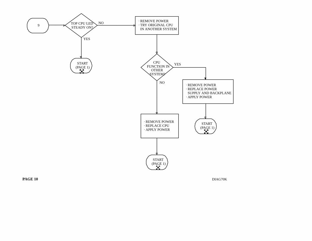
ÁÁÁÁÁ
ÁÁÁÁÁ
ÁÁÁÁÁ
9
ÁÁÁÁÁÁÁÁ
ÁÁÁÁÁÁÁÁ
ÁÁÁÁÁÁÁÁ
ÁÁÁÁÁÁÁÁ
· REMOVE POWER· TRY ORIGINAL CPU IN ANOTHER SYSTEM
ÁÁÁÁ
ÁÁÁÁ
ÁÁÁÁ
ÁÁÁÁ
START(PAGE 1)
NO
ÁÁÁÁÁÁÁ
ÁÁÁÁÁÁÁ
ÁÁÁÁÁÁÁ
ÁÁÁÁÁÁÁ
ÁÁÁÁÁÁÁ
TOP CPU LEDSTEADY ON?
YES
YES
ÁÁÁÁÁÁ
ÁÁÁÁÁÁ
ÁÁÁÁÁÁ
ÁÁÁÁÁÁ
ÁÁÁÁÁÁ
ÁÁÁÁÁÁ
CPUFUNCTION IN
OTHERSYSTEM?
NO ÁÁÁÁÁÁÁÁ
ÁÁÁÁÁÁÁÁ
ÁÁÁÁÁÁÁÁ
ÁÁÁÁÁÁÁÁ
ÁÁÁÁÁÁÁÁ
· REMOVE POWER· REPLACE POWER SUPPLY AND BACKPLANE· APPLY POWER
ÁÁ
ÁÁÁÁÁÁÁÁ
ÁÁÁÁÁÁ
ÁÁÁÁÁÁ
ÁÁÁÁÁÁ
ÁÁÁÁÁÁ
· REMOVE POWER· REPLACE CPU· APPLY POWER
ÁÁÁÁ
ÁÁÁÁ
ÁÁÁÁ
ÁÁÁÁSTART
(PAGE 1)
Á
Á
ÁÁ
ÁÁÁÁ
Á
ÁÁÁÁ
ÁÁÁÁÁ
ÁÁÁÁÁ
ÁÁÁÁÁ
ÁÁÁÁÁ
4(PAGE 5)
ÁÁÁÁÁ
ÁÁÁÁÁ
ÁÁÁÁÁ
ÁÁÁÁÁ
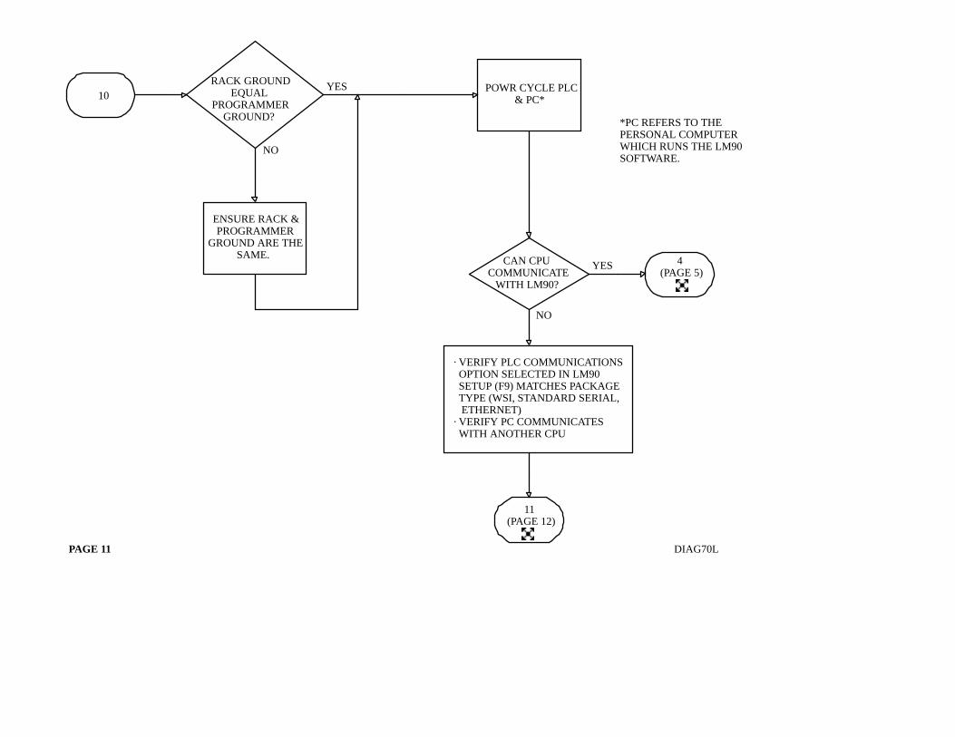
10
NO
ÁÁÁÁÁÁÁÁ
ÁÁÁÁÁÁÁÁ
ÁÁÁÁÁÁÁÁ
ÁÁÁÁÁÁÁÁ
ÁÁÁÁÁÁÁÁ
ÁÁÁÁÁÁÁÁ
ÁÁÁÁÁÁÁÁ
RACK GROUNDEQUAL
PROGRAMMERGROUND?
YES
ÁÁ
ÁÁ
ÁÁÁÁÁÁÁ
ÁÁÁÁÁÁÁ
ÁÁÁÁÁÁÁ
ÁÁÁÁÁÁÁ
ÁÁÁÁÁÁÁ
ENSURE RACK &PROGRAMMER
GROUND ARE THESAME.
ÁÁÁÁÁÁÁ
ÁÁÁÁÁÁÁ
ÁÁÁÁÁÁÁ
ÁÁÁÁÁÁÁ
ÁÁÁÁÁÁÁ
POWR CYCLE PLC& PC*Á
DIAG70LPAGE 11
ÁÁÁÁÁÁÁ
ÁÁÁÁÁÁÁ
ÁÁÁÁÁÁÁ
ÁÁÁÁÁÁÁ
ÁÁÁÁÁÁÁ
CAN CPUCOMMUNICATE
WITH LM90?
YES
NO
ÁÁ
ÁÁ
ÁÁÁÁÁÁÁÁÁÁÁ
ÁÁÁÁÁÁÁÁÁÁÁ
ÁÁÁÁÁÁÁÁÁÁÁ
ÁÁÁÁÁÁÁÁÁÁÁ
ÁÁÁÁÁÁÁÁÁÁÁ
ÁÁÁÁÁÁÁÁÁÁÁ
ÁÁÁÁÁÁÁÁÁÁÁ
· VERIFY PLC COMMUNICATIONS OPTION SELECTED IN LM90 SETUP (F9) MATCHES PACKAGE TYPE (WSI, STANDARD SERIAL, ETHERNET)· VERIFY PC COMMUNICATES WITH ANOTHER CPU
*PC REFERS TO THEPERSONAL COMPUTERWHICH RUNS THE LM90SOFTWARE.
ÁÁÁÁÁ
ÁÁÁÁÁ
ÁÁÁÁÁ
ÁÁÁÁÁ
11(PAGE 12)
Á
Á
DIAG70MPAGE 12
ÁÁÁÁÁ
ÁÁÁÁÁ
ÁÁÁÁÁ
12(PAGE 13)
ÁÁÁÁÁ
ÁÁÁÁÁ
ÁÁÁÁÁ
ÁÁÁÁÁ
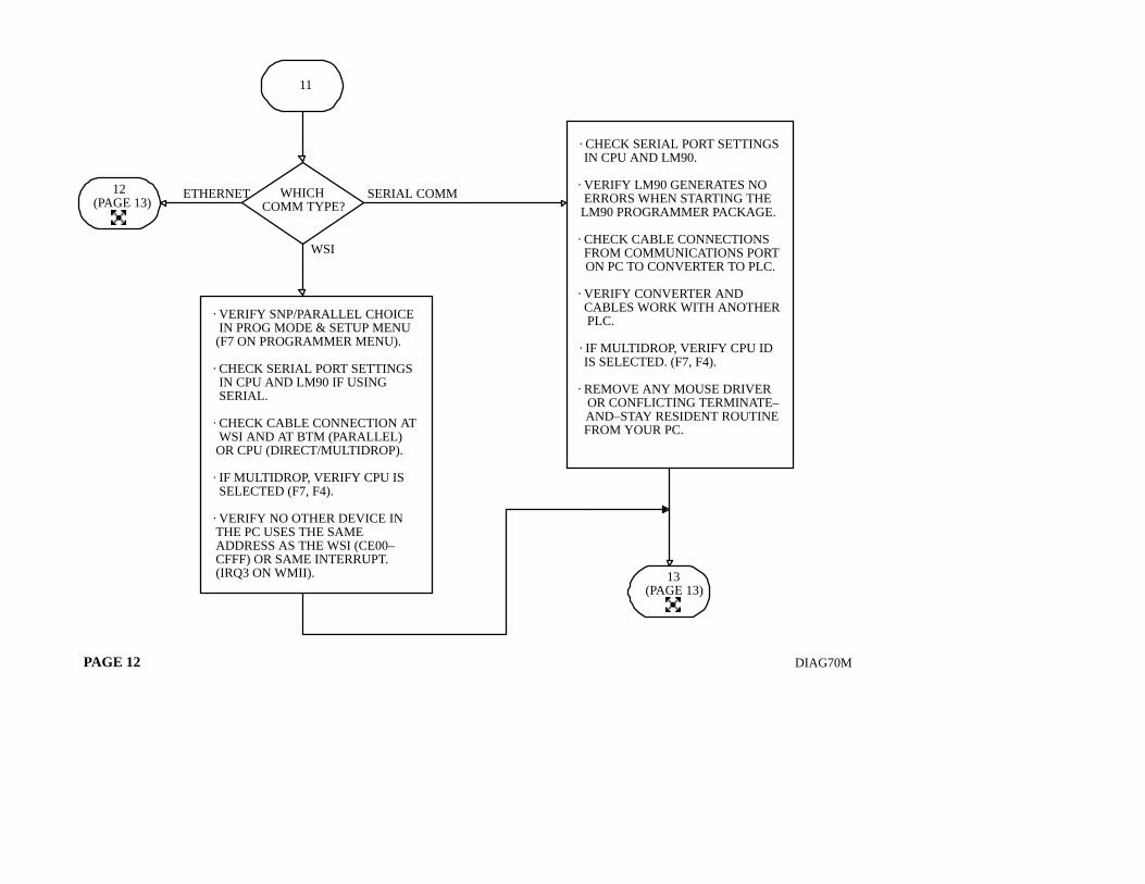
11
ÁÁÁÁÁÁÁ
ÁÁÁÁÁÁÁ
ÁÁÁÁÁÁÁ
ÁÁÁÁÁÁÁ
ÁÁÁÁÁÁÁ
WHICHCOMM TYPE?
ÁÁÁÁÁÁÁÁÁÁ
ÁÁÁÁÁÁÁÁÁÁ
ÁÁÁÁÁÁÁÁÁÁ
ÁÁÁÁÁÁÁÁÁÁ
ÁÁÁÁÁÁÁÁÁÁ
ÁÁÁÁÁÁÁÁÁÁ
ÁÁÁÁÁÁÁÁÁÁ
ÁÁÁÁÁÁÁÁÁÁ
ÁÁÁÁÁÁÁÁÁÁ
ÁÁÁÁÁÁÁÁÁÁ
ÁÁÁÁÁÁÁÁÁÁ
ÁÁÁÁÁÁÁÁÁÁ
ÁÁÁÁÁÁÁÁÁÁ
ÁÁÁÁÁÁÁÁÁÁ
ÁÁÁÁÁÁÁÁÁÁ
ÁÁÁÁÁÁÁÁÁÁ
ÁÁÁÁÁÁÁÁÁÁ
· CHECK SERIAL PORT SETTINGS IN CPU AND LM90.
· VERIFY LM90 GENERATES NO ERRORS WHEN STARTING THE LM90 PROGRAMMER PACKAGE.
· CHECK CABLE CONNECTIONS FROM COMMUNICATIONS PORT ON PC TO CONVERTER TO PLC.
· VERIFY CONVERTER AND CABLES WORK WITH ANOTHER PLC.
· IF MULTIDROP, VERIFY CPU ID IS SELECTED. (F7, F4).
· REMOVE ANY MOUSE DRIVER OR CONFLICTING TERMINATE– AND–STAY RESIDENT ROUTINE FROM YOUR PC.
ÁÁÁÁÁÁÁÁÁÁ
ÁÁÁÁÁÁÁÁÁÁ
ÁÁÁÁÁÁÁÁÁÁ
ÁÁÁÁÁÁÁÁÁÁ
ÁÁÁÁÁÁÁÁÁÁ
ÁÁÁÁÁÁÁÁÁÁ
ÁÁÁÁÁÁÁÁÁÁ
ÁÁÁÁÁÁÁÁÁÁ
ÁÁÁÁÁÁÁÁÁÁ
ÁÁÁÁÁÁÁÁÁÁ
ÁÁÁÁÁÁÁÁÁÁ
ÁÁÁÁÁÁÁÁÁÁ
ÁÁÁÁÁÁÁÁÁÁ
ÁÁÁÁÁÁÁÁÁÁ
· VERIFY SNP/PARALLEL CHOICE IN PROG MODE & SETUP MENU (F7 ON PROGRAMMER MENU).
· CHECK SERIAL PORT SETTINGS IN CPU AND LM90 IF USING SERIAL.
· CHECK CABLE CONNECTION AT WSI AND AT BTM (PARALLEL) OR CPU (DIRECT/MULTIDROP).
· IF MULTIDROP, VERIFY CPU IS SELECTED (F7, F4).
· VERIFY NO OTHER DEVICE IN THE PC USES THE SAME ADDRESS AS THE WSI (CE00– CFFF) OR SAME INTERRUPT. (IRQ3 ON WMII). ÁÁÁÁÁ
ÁÁÁÁ
ÁÁÁÁ
13(PAGE 13)
SERIAL COMM
WSI
ETHERNET
Á
Á
Á
Á
ÁÁÁÁ
DIAG70NPAGE 13
ÁÁÁÁÁÁÁÁÁÁ
ÁÁÁÁÁÁÁÁÁÁ
ÁÁÁÁÁÁÁÁÁÁ
ÁÁÁÁÁÁÁÁÁÁ
ÁÁÁÁÁÁÁÁÁÁ
ÁÁÁÁÁÁÁÁÁÁ
ÁÁÁÁÁÁÁÁÁÁ
ÁÁÁÁÁÁÁÁÁÁ
ÁÁÁÁÁÁÁÁÁÁ
ÁÁÁÁÁÁÁÁÁÁ
ÁÁÁÁÁÁÁÁÁÁ
ÁÁÁÁÁÁÁÁÁÁ
ÁÁÁÁÁÁÁÁÁÁ
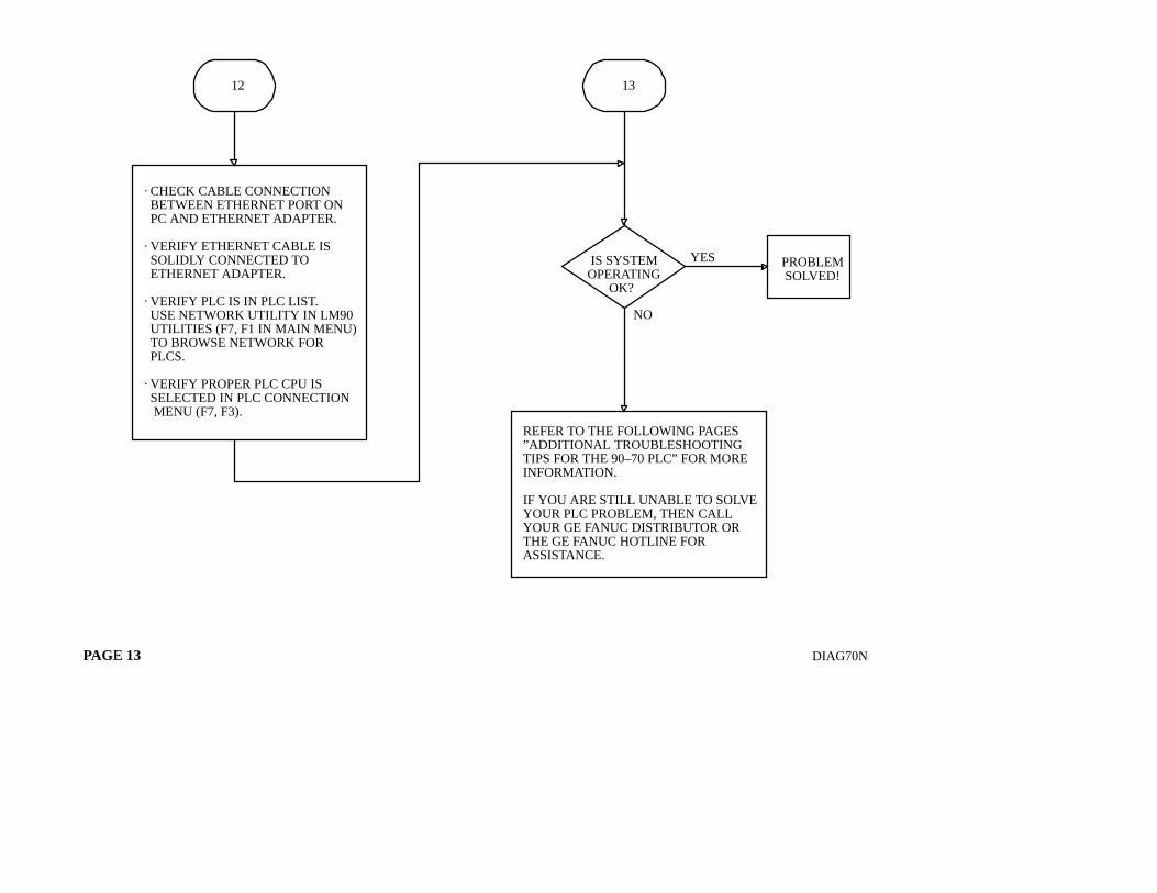
· CHECK CABLE CONNECTION BETWEEN ETHERNET PORT ON PC AND ETHERNET ADAPTER.
· VERIFY ETHERNET CABLE IS SOLIDLY CONNECTED TO ETHERNET ADAPTER.
· VERIFY PLC IS IN PLC LIST. USE NETWORK UTILITY IN LM90 UTILITIES (F7, F1 IN MAIN MENU) TO BROWSE NETWORK FOR PLCS.
· VERIFY PROPER PLC CPU IS SELECTED IN PLC CONNECTION MENU (F7, F3).
ÁÁÁÁÁ
ÁÁÁÁÁ
ÁÁÁÁÁ
ÁÁÁÁÁ
13
ÁÁÁÁÁ
ÁÁÁÁÁ
ÁÁÁÁÁ
ÁÁÁÁÁ
12
Á
ÁÁÁÁÁÁÁÁÁÁÁ
ÁÁÁÁÁÁÁÁÁÁÁ
ÁÁÁÁÁÁÁÁÁÁÁ
ÁÁÁÁÁÁÁÁÁÁÁ
ÁÁÁÁÁÁÁÁÁÁÁ
ÁÁÁÁÁÁÁÁÁÁÁ
ÁÁÁÁÁÁÁÁÁÁÁ
ÁÁÁÁÁÁÁÁÁÁÁ
REFER TO THE FOLLOWING PAGES”ADDITIONAL TROUBLESHOOTINGTIPS FOR THE 90–70 PLC” FOR MOREINFORMATION.
IF YOU ARE STILL UNABLE TO SOLVEYOUR PLC PROBLEM, THEN CALLYOUR GE FANUC DISTRIBUTOR ORTHE GE FANUC HOTLINE FORASSISTANCE.
ÁÁÁÁÁÁ
ÁÁÁÁÁÁ
ÁÁÁÁÁÁ
ÁÁÁÁÁÁ
IS SYSTEMOPERATING
OK?
ÁÁÁÁ
ÁÁÁÁ
ÁÁÁÁ
ÁÁÁÁ
PROBLEMSOLVED!
Á
ÁÁÁÁ
YES
NO
ÁÁ
Á