ge fanuc automation ge fanuc automation, we strive to produce quality technical documentation. after...
TRANSCRIPT
Î
GE Fanuc Automation
Programmable Control Products
Series 90�–70
Genius� Bus Controller
User’s Manual
GFK–0398C June 1992

GFL–002
Warnings, Cautions, and Notesas Used in this Publication
Warning
Warning notices are used in this publication to emphasize that hazardous voltages, cur-rents, temperatures, or other conditions that could cause personal injury exist in thisequipment or may be associated with its use.
In situations where inattention could cause either personal injury or damage to equip-ment, a Warning notice is used.
Caution
Caution notices are used where equipment might be damaged if care is not taken.
Note
Notes merely call attention to information that is especially significant to understandingand operating the equipment.
This document is based on information available at the time of its publication. While ef-forts have been made to be accurate, the information contained herein does not purportto cover all details or variations in hardware or software, nor to provide for every pos-sible contingency in connection with installation, operation, or maintenance. Featuresmay be described herein which are not present in all hardware and software systems.GE Fanuc Automation assumes no obligation of notice to holders of this document withrespect to changes subsequently made.
GE Fanuc Automation makes no representation or warranty, expressed, implied, or stat-utory with respect to, and assumes no responsibility for the accuracy, completeness, suf-ficiency, or usefulness of the information contained herein. No warranties of merchant-ability or fitness for purpose shall apply.
The following are trademarks of GE Fanuc Automation North America, Inc.
Alarm Master CIMSTAR Helpmate PROMACRO Series SixCIMPLICITY GEnet Logicmaster Series One Series 90CIMPLICITY 90–ADS Genius Modelmaster Series Three VuMasterCIMPLICITY PowerTRAC Genius PowerTRAC ProLoop Series Five Workmaster
Copyright 1992 GE Fanuc Automation North America, Inc.All Rights Reserved
iii
Preface
This manual describes the features and operation of the Series 90�–70 Bus Controller. Italso provides the configuration and programming information needed to complete theinterface between a Series 90–70 PLC and a Genius� I/O bus.
If you need information about types of systems, system planning, installation, and sys-tem components, refer to the Genius I/O System User’s Manual (GEK–90486). It is the pri-mary source of information about Genius I/O products.
Preface
Series 90–70 Genius Bus Controller User’s Manual – June 1992iv
Content of this Manual
Chapter 1. Introduction: Chapter 1 describes the Series 90–70 Bus Controller and ex-plains how it operates.
Chapter 2. Installation: Chapter 2 explains how to install or remove a Bus Controller,and how to connect it to a Genius serial bus.
Chapter 3. Bus Controller Configuration: Chapter 3 explains how to complete the Lo-gicmaster configuration steps for a Bus Controller and its bus.
Chapter 4. Diagnostics: Chapter 4 describes diagnostics capabilities of interest in Series90–70 PLC systems that use Genius I/O and communications.
Chapter 5. Communication Request: Chapter 5 describes the use of the COMREQ pro-gram instruction with a Bus Controller.
Chapter 6. Data Monitoring, Distributed Control, and Redundancy: Chapter 6 de-scribes some advanced systems supported by the Series 90–70 Bus Controller.
Appendix A. ASCII Code List: Lists ASCII characters and their decimal and hexadecimalequivalents.
Changes for this Revision of the ManualThis manual describes the new features available with release 4.0 of the Bus Controller,including greater support for redundancy and reference address checking. New andrevised information in this manual includes:
� Revised information on page 13 about completing Shield In and Shield Out connec-tions to a Bus Controller.
� Instructions for configuring reference address checking, bus redundancy and BusController redundancy, in chapter 3.
� Some new and revised diagnostics messages in chapter 4.
� Information about using passwords with COMREQs in chapter 5.
� An expanded description of redundancy features in chapter 6.
� Instructions for determining how many Bus Controllers can be used in a system thatincludes the use of dual (redundant) busses.

Preface
vChapter Title Here
Related Publications
For more information, refer to these publications:
Genius I/O System User’s Manual (GEK–90486–1). Reference manual for system design-ers, programmers, and others involved in integrating Genius I/O products in a PLC orhost computer environment. This book provides a system overview, and describes thetypes of systems that can be created using Genius products. Datagrams, Global Data,and data formats are defined.
Genius Discrete and Analog Blocks User’s Manual (GEK–90486–2). Reference manualfor system designers, operators, maintenance personnel, and others using Genius dis-crete and analog I/O blocks. This book contains a detailed description, specifications,installation instructions, and configuration instructions for all currently–available dis-crete and analog blocks.
Series 90–70 PLC Installation and Operation Manual (GFK–0262). This book describesthe modules of a Series 90–70 PLC system, and explains system setup and operation.
Logicmaster 90–70 User’s Manual (GFK–0263). Reference manual for system operatorsand others using the Logicmaster 90–70 software to program, configure, monitor, orcontrol a Series 90–70 PLC and/or a remote drop.
Logicmaster 90 Software Reference Manual (GFK–0265). Reference manual which de-scribes program structure and defines program instructions for the Series 90–70 PLC.
Series 90–70 Remote I/O Scanner User’s Manual (GFK–0579). Reference manual for theRemote I/O Scanner, which interfaces a drop containing Series 90–70 modules to a Ge-nius bus. Any CPU capable of controlling the bus can be used as the host. This book de-scribes the Remote I/O Scanner features, configuration, and operation.
Series Six� Bus Controller User’s Manual (GFK–0171). Reference manual for the BusController, which interfaces a Genius bus to a Series Six PLC. This book describes theinstallation and operation of the Bus Controller. It also contains the programming in-formation needed to interface Genius I/O devices to a Series Six PLC.
Series Five� Bus Controller User’s Manual (GFK–0248). Reference manual for the BusController, which interfaces a Genius bus to a Series Five PLC. This book describes theinstallation and operation of the Bus Controller. It also contains the programming in-formation needed to interface Genius I/O devices to a Series Five PLC.
Genius I/O PCIM User’s Manual (GFK–0074). Reference manual for the PCIM, whichinterfaces a Genius bus to a suitable host computer. This book describes the installationand operation of the PCIM. It also contains the programming information needed to in-terface Genius I/O devices to a host computer.
Preface
Series 90–70 Genius Bus Controller User’s Manual – June 1992vi
We Welcome Your Comments and Suggestions
At GE Fanuc automation, we strive to produce quality technical documentation. Afteryou have used this manual, please take a few moments to complete and return theReader ’s Comment Card located on the next page.
Jeanne L. GrimsbySenior Technical Writer
Contents
vii
GFK–0398C Series 90–70 Genius Bus Controller User’s Manual – June 1992
Chapter 1 Introduction 1 . . . . . . . . . . . . . . . . . . . . . . . . . . . . . . . . . . . . . . . . . . . . . . .
System Overview 1 . . . . . . . . . . . . . . . . . . . . . . . . . . . . . . . . . . . . . . . . . . . . . . . . .
I/O Devices on the Bus 2 . . . . . . . . . . . . . . . . . . . . . . . . . . . . . . . . . . . . . . . . . . . .
Bus Controller Description 3 . . . . . . . . . . . . . . . . . . . . . . . . . . . . . . . . . . . . . . . . .
The Genius Bus 4 . . . . . . . . . . . . . . . . . . . . . . . . . . . . . . . . . . . . . . . . . . . . . . . . . .
Bus Controller Operation 5 . . . . . . . . . . . . . . . . . . . . . . . . . . . . . . . . . . . . . . . . . .
Datagrams 8 . . . . . . . . . . . . . . . . . . . . . . . . . . . . . . . . . . . . . . . . . . . . . . . . . . . . . . .
Global Data 9 . . . . . . . . . . . . . . . . . . . . . . . . . . . . . . . . . . . . . . . . . . . . . . . . . . . . . .
Chapter 2 Installation 11 . . . . . . . . . . . . . . . . . . . . . . . . . . . . . . . . . . . . . . . . . . . . . . . .
Installing the Bus Controller 12 . . . . . . . . . . . . . . . . . . . . . . . . . . . . . . . . . . . . . . . .
Removing the Bus Controller 12 . . . . . . . . . . . . . . . . . . . . . . . . . . . . . . . . . . . . . . .
Connecting the Serial Bus 13 . . . . . . . . . . . . . . . . . . . . . . . . . . . . . . . . . . . . . . . . . .
Chapter 3 Bus Controller Configuration 15 . . . . . . . . . . . . . . . . . . . . . . . . . . . . . . . .
Configuration Overview 15 . . . . . . . . . . . . . . . . . . . . . . . . . . . . . . . . . . . . . . . . . . .
Configuring a Bus Controller 16 . . . . . . . . . . . . . . . . . . . . . . . . . . . . . . . . . . . . . . .
Configuring Devices on the Bus 24 . . . . . . . . . . . . . . . . . . . . . . . . . . . . . . . . . . . .
Bus Controller Configuration Steps 39 . . . . . . . . . . . . . . . . . . . . . . . . . . . . . . . . . .
Chapter 4 Diagnostics 53 . . . . . . . . . . . . . . . . . . . . . . . . . . . . . . . . . . . . . . . . . . . . . . .
System Status References 54 . . . . . . . . . . . . . . . . . . . . . . . . . . . . . . . . . . . . . . . . . .
Fault and No Fault Contacts 55 . . . . . . . . . . . . . . . . . . . . . . . . . . . . . . . . . . . . . . . .
High Alarm and Low Alarm Contacts 56 . . . . . . . . . . . . . . . . . . . . . . . . . . . . . . .
Fault Table 57 . . . . . . . . . . . . . . . . . . . . . . . . . . . . . . . . . . . . . . . . . . . . . . . . . . . . . . .
Fault Table Definitions 59 . . . . . . . . . . . . . . . . . . . . . . . . . . . . . . . . . . . . . . . . . . . . .

Contents
viii
GFK–0398C Series 90–70 Genius Bus Controller User’s Manual – June 1992
Chapter 5 Communication Requests 63 . . . . . . . . . . . . . . . . . . . . . . . . . . . . . . . . . . .
COMREQs and Passwords 63 . . . . . . . . . . . . . . . . . . . . . . . . . . . . . . . . . . . . . . . . .
Programming for a Communication Request 64 . . . . . . . . . . . . . . . . . . . . . . . . .
COMREQ Command Block Format 65 . . . . . . . . . . . . . . . . . . . . . . . . . . . . . . . . .
The COMREQ Instruction 68 . . . . . . . . . . . . . . . . . . . . . . . . . . . . . . . . . . . . . . . . .
COMREQs and Datagrams 74 . . . . . . . . . . . . . . . . . . . . . . . . . . . . . . . . . . . . . . . .
COMREQ #1: Pulse Test Command 75 . . . . . . . . . . . . . . . . . . . . . . . . . . . . . . . . .
COMREQ #2: Read Configuration Command 76 . . . . . . . . . . . . . . . . . . . . . . . .
COMREQ #3: Write Configuration Command 77 . . . . . . . . . . . . . . . . . . . . . . . .
COMREQ #4: Read Diagnostics Command 78 . . . . . . . . . . . . . . . . . . . . . . . . . .
COMREQ #5: Clear Circuit Faults Command 79 . . . . . . . . . . . . . . . . . . . . . . . . .
COMREQ #6: Clear All Circuit Faults Command 79 . . . . . . . . . . . . . . . . . . . . . .
COMREQ #7: Assign Monitor Command 80 . . . . . . . . . . . . . . . . . . . . . . . . . . . .
COMREQ #8: Enable/Disable Outputs Command 82 . . . . . . . . . . . . . . . . . . . .
COMREQ #9: Enable/Disable Global Data 83 . . . . . . . . . . . . . . . . . . . . . . . . . . .
COMREQ #10: Switch BSM Command 84 . . . . . . . . . . . . . . . . . . . . . . . . . . . . . .
COMREQ #11: Read Device Command 85 . . . . . . . . . . . . . . . . . . . . . . . . . . . . .
COMREQ #12: Write Device Command 90 . . . . . . . . . . . . . . . . . . . . . . . . . . . . .
COMREQ #13: Dequeue Datagram Command 91 . . . . . . . . . . . . . . . . . . . . . . .
COMREQ #14: Send Datagram Command 94 . . . . . . . . . . . . . . . . . . . . . . . . . . .
COMREQ #15: Request Datagram Reply Command 97 . . . . . . . . . . . . . . . . . .
COMREQ #16: Enable/Disable I/O Fault Categories 98 . . . . . . . . . . . . . . . . . . .
Chapter 6 Data Monitoring, Distributed Control,and Redundancy 99 . . . . . . . . . . . . . . . . . . . . . . . . . . . . . . . . . . . . . . . .
Data Monitoring 100 . . . . . . . . . . . . . . . . . . . . . . . . . . . . . . . . . . . . . . . . . . . . . . . . . .
Distributed Control 101 . . . . . . . . . . . . . . . . . . . . . . . . . . . . . . . . . . . . . . . . . . . . . . .
Redundancy 102 . . . . . . . . . . . . . . . . . . . . . . . . . . . . . . . . . . . . . . . . . . . . . . . . . . . . .
Appendix A ASCII Code List 117 . . . . . . . . . . . . . . . . . . . . . . . . . . . . . . . . . . . . . . . . . . .
1 section level 1 1figure bi level 1 table_big level 1
Restarts for autonumbers that do not restart in each chapter. figure bi level 1, reset table_big level 1, reset chap_big level 1, reset1 app_biglevel 1, resetA figure_ap level 1, reset table_ap level 1, reset figure level 1, reset Figure 1. table level 1, reset Table 1. these restarts must bein the header frame of chapter 1. a:ebx, l 1 resetA a:obx:l 1, resetA a:bigbx level 1 resetA a:ftr level 1 resetA c:ebx, l 1 reset1 c:obx:l 1, reset1c:bigbx level 1 reset1 c:ftr level 1 reset1 Reminders for autonumbers that need to be restarted manually (first instance will always be 4)let_in level 1: letter level 1:A.B.C. num level 1: 1. 2. 3. num_in level 1: 1. 2. 3. rom_in level 1: I. II. III. roman level 1: I. II. III. steps level 1:1. 2. 3.
1
Chapter 1 Introduction
This chapter describes the Series 90–70 PLC Bus Controller and its operation.
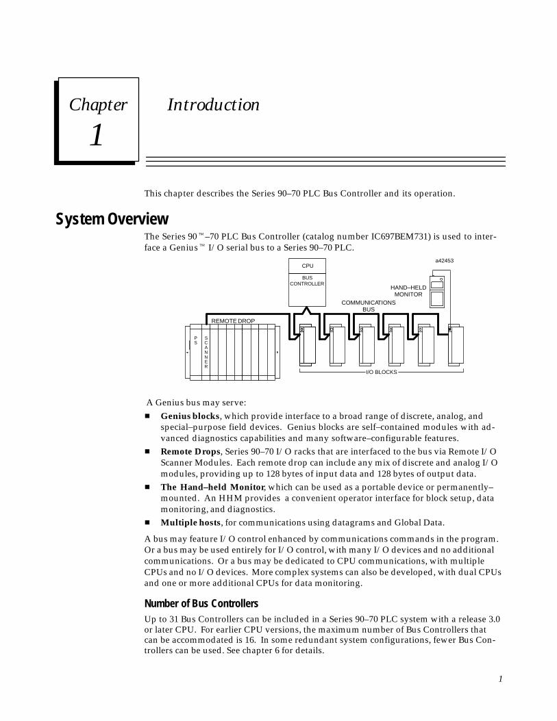
System OverviewThe Series 90�–70 PLC Bus Controller (catalog number IC697BEM731) is used to inter-face a Genius� I/O serial bus to a Series 90–70 PLC.
ÎÎÎÎÎÎÎÎÎÎ
ÎÎÎÎÎÎÎÎÎÎ
ÎÎÎÎÎ
ÎÎÎÎÎ
ÎÎÎÎÎÎÎÎÎÎ
ÎÎÎÎÎ
ÎÎÎÎÎÎÎÎÎÎ
ÎÎÎÎÎÎÎÎÎÎ
ÎÎÎÎÎ
ÎÎÎÎÎÎÎÎÎÎ
Î Î
REMOTE DROP
A
SC
NNER
BUSCONTROLLER
CPUa42453
COMMUNICATIONSBUS
HAND–HELDMONITOR
I/O BLOCKS
PS
A Genius bus may serve:� Genius blocks, which provide interface to a broad range of discrete, analog, and
special–purpose field devices. Genius blocks are self–contained modules with ad-vanced diagnostics capabilities and many software–configurable features.
� Remote Drops, Series 90–70 I/O racks that are interfaced to the bus via Remote I/OScanner Modules. Each remote drop can include any mix of discrete and analog I/Omodules, providing up to 128 bytes of input data and 128 bytes of output data.
� The Hand–held Monitor, which can be used as a portable device or permanently–mounted. An HHM provides a convenient operator interface for block setup, datamonitoring, and diagnostics.
� Multiple hosts, for communications using datagrams and Global Data.
A bus may feature I/O control enhanced by communications commands in the program.Or a bus may be used entirely for I/O control, with many I/O devices and no additionalcommunications. Or a bus may be dedicated to CPU communications, with multipleCPUs and no I/O devices. More complex systems can also be developed, with dual CPUsand one or more additional CPUs for data monitoring.
Number of Bus ControllersUp to 31 Bus Controllers can be included in a Series 90–70 PLC system with a release 3.0or later CPU. For earlier CPU versions, the maximum number of Bus Controllers thatcan be accommodated is 16. In some redundant system configurations, fewer Bus Con-trollers can be used. See chapter 6 for details.

1
Series 90–70 Genius Bus Controller User’s Manual – June 19922
I/O Devices on the Bus
The I/O devices on a bus may be Genius I/O blocks, or standard Series 90–70 I/O mod-ules in one or more remote drops. The total number of I/O circuits that can be served byone Genius bus depends on the types of I/O devices that are used and the memoryavailable in the CPU.
Memor y Required for Genius BlocksMemory requirements for Genius I/O blocks are shown below. For %I and %Q memory,the sizes shown are in bits. For %AI and %AQ memory, the sizes shown are in words.
Block TypeMaximum Memory Requirements
Block Type %I (bits) %Q (bits) %AI (words) %AQ (words)
115 VAC Grouped I/O blocks 8 8115 VAC Isolated I/O blocks 8 816 Ckt AC Input Block 1616 Ckt DC Sink/source blocks 16 1632 Ckt DC Sink/source blocks 32 32Relay Output blocks 164 Input/2 Output Analog Blocks 4 2Current–source Analog I/O Blocks 4 2Current–source Analog Output Blocks 6RTD Input blocks 6Thermocouple blocks 6High–speed Counter 16 16 15PowerTRAC Module 16 16 18
Many Genius I/O blocks have both inputs and outputs on the same block. Blocks config-ured in the Logicmaster 90 software as having both inputs and outputs will occupy iden-tical references in both %I and %Q memory, regardless of the block’s software configu-ration. Unused references cannot be assigned to other inputs or outputs, and should notbe used in the application program.
Memor y Required for a Remote DropTogether, one 90–70 Remote I/O Scanner (IC697BEM733) and the modules it servesmake up a remote drop on the Genius bus.
PS
GENIUS BUSALL RACKS MUST BE AT THE SAME GROUND POTENTIAL
RACK 7
PS
ÎÎ
BRM
a44875
NOTE:
PS
A
SC
NNER
RACK 1
ÎÎ
BRM
BTM
RACK 6
PS
ÎÎ
BRM
UP TO 50 FEET
Î
REMOTE DROP
RACK 0
The remote drop can include any mix of Series 90–70 discrete and analog input and out-put modules, up to a total of 128 bytes of inputs and 128 bytes of outputs (8 discretepoints represent one byte and 1 analog channel uses 2 bytes).

1
3Chapter 1 Introduction
Bus Controller Description
The Bus Controller is a standard, rack–mounted Series 90–70 PLC module.
LEDs
HHM CONNECTOR
REMOVABLEBUS WIRINGTERMINALASSEMBLY
a43523
ÎÎÎÎ
Î
ÎÎÎÎÎÎÎÎÎÎÎÎ
ÎÎÎÎÎÎÎÎÎÎÎÎ
ÎÎÎÎÎÎÎÎÎÎÎÎ
ÎÎÎÎÎÎÎÎ
Status LEDsThe LEDs on the front of the Bus Controller indicate its operating status. The top twoLEDs should be on during normal operation. The bottom LED is not used.
Shows the status of the Bus Controller. This LED blinks during power-up diagnostics.
Shows the status of the bus. This LED is on steadily when the bus isoperating properly. It blinks for intermittent bus errors and is off for afailed bus. It is also off when no configuration has been received fromthe PLC CPU.
Hand–held Monitor ConnectorThe Hand–held Monitor connector on the Bus Controller faceplate provides attachmentfor a Hand–held Monitor. For Bus Controller IC697BEM931, the lower HHM connector,if present, is not used. All Hand–held Monitor functions except I/O block Device Num-ber assignment can be performed with the HHM connected to the Bus Controller. Busand block operation can be monitored, circuits forced or unforced, outputs Pulse Tested,diagnostic messages displayed, and faults cleared, from this convenient central location.Hand–held Monitor version IC660HHM501C (or later), permitting selection of a “hostCPU” is recommended for proper operation with the Series 90–70 PLC.
Terminal AssemblySerial bus and shield wiring connections are made to the removable terminal strip on thefront of the Bus Controller. For Bus Controller IC697BEM931, only the upper three ter-minals are used. To remove the Terminal Assembly without disturbing the continuity ofthe bus, jumpers are used. See chapter 2.
Module OK
Channel OK

1
Series 90–70 Genius Bus Controller User’s Manual – June 19924
The Genius Bus
The Genius bus is a shielded twisted–pair wire, daisy–chained between devices, andterminated at both ends. Proper cable selection is critical to successful operation of thesystem. Suitable cable types are listed in the Genius I/O System User’s Manual.
Conservative wiring practices, as well as national and local codes, require physical sepa-ration between control circuits and power distribution or motor power. Refer to sections430 and 725 of the National Electric Code.
Bus Type Daisy–chained bus cable; single twisted pair plus shield or Twinax.Fiber optics cable and modems can also be used.
Bus Termination 75, 100, 120, or 150 ohm resistor at both ends of electrical bus cable.
Baud Rate Configurable. 153.6 Kbaud standard, 153.6 Kbaud extended, 76.8Kbaud, or 38.4 Kbaud.
Maximum Bus Length 7500 feet at 38.4 Kbaud, 4500 feet at 76.8 Kbaud, 3500 feet at 153.6Kbaud extended, 2000 feet at 153.6 Kbaud, standard. Maximumlength at each baud rate also depends on cable type. Chapter 2 pro-vides a complete list of cable types, showing corresponding buslengths and baud rates.
Greater bus lengths are possible using sections of fiber optics cablewith modems.
Maximum Number ofDevices
32 devices at 153.6 Kbaud standard, 153.6 Kbaud extended, or 76.8Kbaud. 16 devices at 38.4 Kbaud. Includes bus controller and typi-cally a Hand–held Monitor.
Data Encoding Each bit is encoded into three dipulses, majority voted at the receiverto correct any single dipulse errors. A dipulse is an AC code consist-ing of a positive then negative excursion of voltage. Dipulses areindividually sampled to reject low and high frequency interference.
Modulation Technique Frequency Shift Keying (FSK) 0 to 460.8 KHz max. (153.6 Kilobaud)
Isolation 2000 volts Hi–Pot, 1500 volts transient common mode rejection.
Signal/noise Ratio 60 db

1
5Chapter 1 Introduction
Bus Controller Operation
The Bus Controller handles all data transfer between the PLC and the devices on its bus.In order to do this, the Bus Controller must interface two completely separate andasynchronous activities:
A. The Genius bus scan, a cycle of communications between the devices on a bus (in-cluding the Bus Controller itself). The cycle follows the order of Bus Addresses(0–31).
B. The CPU sweep, the cycle of actions that includes communications between theCPU and the Bus Controller.
The Bus Controller manages data transfer between the bus and the CPU by maintainingtwo separate on–board RAM memories. One interfaces with the bus and the other in-terfaces with the CPU. The Bus Controller automatically transfers data between thesetwo memories, making data available to the bus or to the CPU when it is needed.
The Genius Bus Scan
A bus scan consists of one complete rotation of a “token” among the devices on the bus.
a43528
TOKEN PATH
2 3
ÎÎÎÎÎ
BUSCONTROLLER
(DEVICE 31)
301
As mentioned earlier, these devices may include other Bus Controllers, or Remote I/OScanners, in addition to (or instead of) the Genius blocks illustrated above.
During a bus scan, the Bus Controller automatically:
� Receives all input data that has been sent by devices on the bus.
� Broadcasts Global Data.
� Updates outputs, as permitted, to the devices on the bus. Transmission of outputsfrom the Bus Controller can be disabled for one or more devices on the bus.
� Receives any fault messages issued by devices on the bus and sets diagnostic statusreferences for use by the CPU.
� Sends a single command received from the CPU (for example, Clear Circuit Faults)to the appropriate devices.
The amount of time it takes for the communications token to pass to all devices dependson the baud rate, the number and types of devices on the bus, and the use of GlobalData and datagram communications.

1
Series 90–70 Genius Bus Controller User’s Manual – June 19926
Input Data from Devices on the Bus
The Bus Controller receives input data from each input block, I/O block, and remotedrop each time the block or Remote I/O Scanner has the communications token. (Be-cause this data is broadcast, it may be received by any other bus interface module oper-ating on the bus).
INPUTSFROM BLOCK 4
1 2 3 4
BUSCONTROLLER
a43559
= TOKEN
The Bus Controller stores all the input data it receives. Once per CPU sweep, the CPUreads all discrete and analog inputs from the Bus Controller. (Analog data is not multi-plexed).
Output Data from the CPU
As the application program executes, the CPU sends outputs and any commands to theBus Controller. The Bus Controller stores this data, transmitting it on the bus each timeit has the communications token. Unlike inputs, which are broadcast, outputs are di-rected to the specific device that should receive them.
BUSCONTROLLER
HASTOKEN
1 2 3 4
BUSCONTROLLER
a43557OUTPUTS
PLC CPU
READS STORED INPUTS
STORES NEW OUTPUTS
TOKEN
Outputs for 4 Input/2 Output Analog BlocksFour words of %AQ memory are assigned to a 4 Input/2 Output block by the configura-tion software. The CPU stores the output data as shown below. Locations “n+2” and“n+3” are not used by the block.
not used not used channel 2 channel 1
nn+1n+2n+3 %AQ

1
7Chapter 1 Introduction
Diagnostics
Genius blocks and other devices on the bus will automatically report faults, alarms andcertain other predefined conditions to the PLC.
INPUTS AND FAULT MESSAGEFROM BLOCK 3
1 2 3 4
BUSCONTROLLER
a43556
F FF
TOKEN
FAULT
Only one diagnostic message can be sent during any bus scan. If a fault message hasalready been sent (by another device) during that scan, a device saves its own diagnosticmessage until the next available bus scan. For example, if the communications token iscurrently at device 2, and faults occur at devices 3 and 4 at the same time, device 3 cansend its diagnostic message if another message has not already been sent. Device 4 mustwait at least one more bus scan to send its diagnostic message.
The Bus Controller stores any diagnostic messages it receives. They are read automati-cally by the Series 90–70 CPU. Faults may then be displayed in the fault table using theLogicmaster 90–70 software and cleared from the programmer. Details are in chapter 4.
A Genius Hand–held Monitor can also be used for diagnostics and fault clearing.
In addition the built–in diagnostics capabilities of Genius devices, the Logicmaster90–70 application program can make use of additional diagnostics mechanisms pro-vided by the Series 90–70 PLC:
� System Status References that have been defined for Genius use.
� Fault and No Fault contacts that can be used to detect fault and lack of fault condi-tions.
� Alarm contacts that can be used to indicate when an analog value has reached anassigned alarm limit.
1
Series 90–70 Genius Bus Controller User’s Manual – June 19928
Datagrams
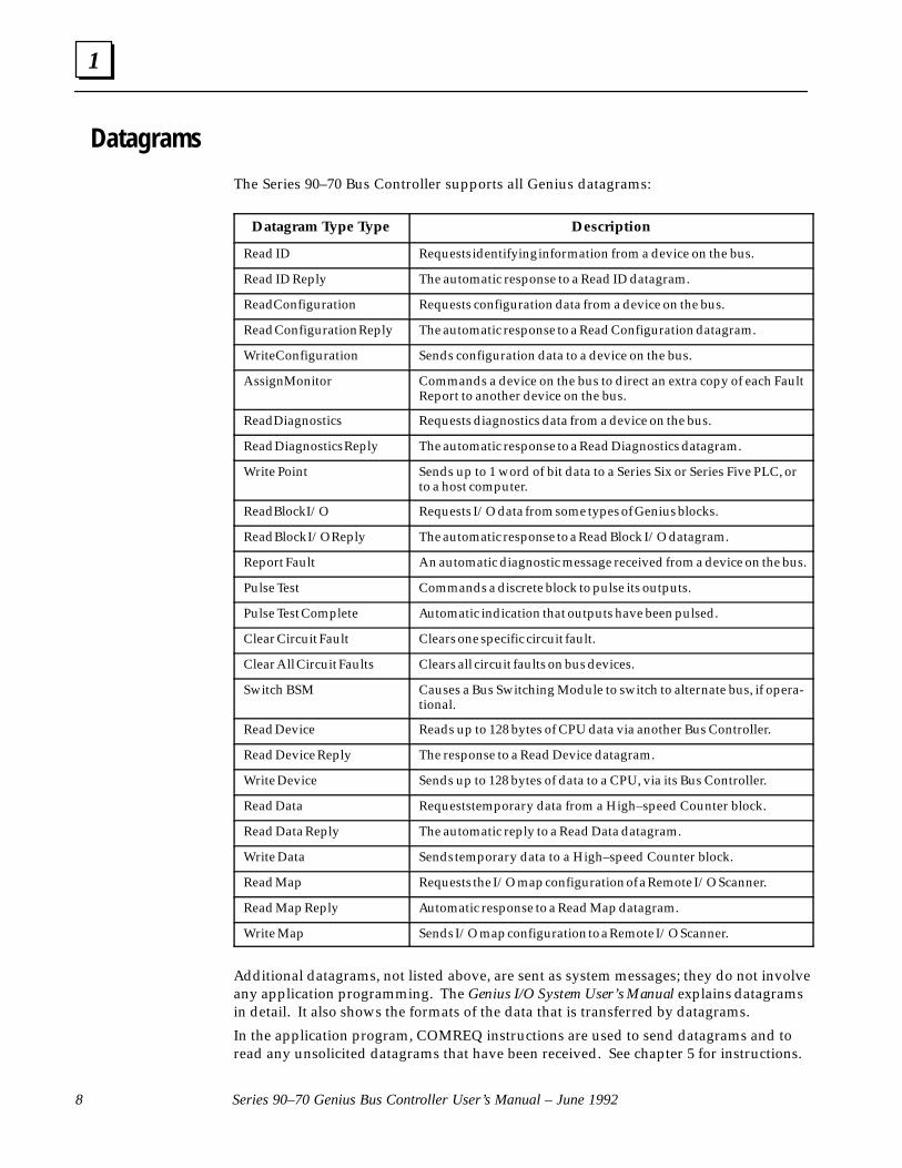
The Series 90–70 Bus Controller supports all Genius datagrams:
Datagram Type Type Description
Read ID Requests identifying information from a device on the bus.
Read ID Reply The automatic response to a Read ID datagram.
Read Configuration Requests configuration data from a device on the bus.
Read Configuration Reply The automatic response to a Read Configuration datagram.
Write Configuration Sends configuration data to a device on the bus.
Assign Monitor Commands a device on the bus to direct an extra copy of each FaultReport to another device on the bus.
Read Diagnostics Requests diagnostics data from a device on the bus.
Read Diagnostics Reply The automatic response to a Read Diagnostics datagram.
Write Point Sends up to 1 word of bit data to a Series Six or Series Five PLC, orto a host computer.
Read Block I/O Requests I/O data from some types of Genius blocks.
Read Block I/O Reply The automatic response to a Read Block I/O datagram.
Report Fault An automatic diagnostic message received from a device on the bus.
Pulse Test Commands a discrete block to pulse its outputs.
Pulse Test Complete Automatic indication that outputs have been pulsed.
Clear Circuit Fault Clears one specific circuit fault.
Clear All Circuit Faults Clears all circuit faults on bus devices.
Switch BSM Causes a Bus Switching Module to switch to alternate bus, if opera-tional.
Read Device Reads up to 128 bytes of CPU data via another Bus Controller.
Read Device Reply The response to a Read Device datagram.
Write Device Sends up to 128 bytes of data to a CPU, via its Bus Controller.
Read Data Requests temporary data from a High–speed Counter block.
Read Data Reply The automatic reply to a Read Data datagram.
Write Data Sends temporary data to a High–speed Counter block.
Read Map Requests the I/O map configuration of a Remote I/O Scanner.
Read Map Reply Automatic response to a Read Map datagram.
Write Map Sends I/O map configuration to a Remote I/O Scanner.
Additional datagrams, not listed above, are sent as system messages; they do not involveany application programming. The Genius I/O System User’s Manual explains datagramsin detail. It also shows the formats of the data that is transferred by datagrams.
In the application program, COMREQ instructions are used to send datagrams and toread any unsolicited datagrams that have been received. See chapter 5 for instructions.

1
9Chapter 1 Introduction
Global Data
Global Data is data which is automatically and repeatedly broadcast by a Bus Controller.The Series 90–70 Bus Controller can send up to 128 bytes of Global Data each bus scan.It can receive up to 128 bytes of Global Data each bus scan from each Bus Controller onits bus.
Sending Global DataOnce set up by configuration (see chapter 3), Global Data is broadcast automatically.Other Bus Controllers receiving the Global Data sent by a Series 90–70 PLC will place itin these memory locations:
Series 90–70 SendsGlobal Data To:
Other CPU Places Global Data in this Memory Location:
Series 90–70 PLC %I, %Q, %G, %R, %AI, %AQ memory if manually–configured, or %Gmemory if automatically–configured. Memory type and beginning ad-dress are chosen during configuration of the receiving bus controller.
Series 90–30 PLC %G memory location corresponding to Device Number (16–23) of theSeries 90–70 Bus Controller that sent the data.
Series Six PLC Register memory. Beginning address selected during configuration ofthe Series 90–70 Bus Controller that sent the data.
Series Five PLC Register memory. Beginning address selected during configuration ofthe Series 90–70 Bus Controller that sent the data.
Computer PCIM or QBIM Input Table Segment corresponding to Device Numberof the Series 90–70 bus controller that sent the data.
Receiving Global DataThe Bus Controller can be configured to receive or ignore Global Data from any otherBus Controller. The memory type and length for incoming Global Data are also selectedduring configuration, as described in chapter 3.
The Series 90–70 CPU can place incoming Global Data in %I, %Q, %G, %R, %AI, or%AQ memory.
Example
In the following example, a Series 90–70 PLC (PLC 1) sends 64 bits of Global Data begin-ning at %I0101 to another Series 90–70 PLC (PLC 2). PLC 2 places this data into its ownmemory beginning at %I0017. PLC 2 sends 8 words of %AQ data beginning at%AQ0001 to PLC 1. PLC 1 places this data into its own memory beginning at %AI0032.
Series 90–70PLC 1
Series 90–70PLC 2
%I0101 – %I0164%AI0032 – %AI0039
%I0017 – %I0081%AQ00001 – %AQ00008
��

2 section level 1 1figure bi level 1 table_big level 1
11
Chapter 2 Installation
This chapter explains:
� How to install and remove a Bus Controller.
� How to connect a Genius serial bus.
� How to terminate a bus if a Bus Controller is physically at either end.
For Additional Information, Also See:
Chapter 1 for a description and illustration of the Bus Controller, explanation of its LEDs,and specifications for the Genius bus.
Chapter 3 for configuration instructions.
Chapter 6 for information about dual bus and dual controller systems.

2
Series 90–70 Genius Bus Controller User’s Manual – June 199212
Installing the Bus Controller
1. Be sure the rack is powered down.
2. Position the Bus Controller at its intended location.
3. Push the Bus Controller into the card guide until it is aligned with the connectoron the rack backplane.
4. Pressing the upper and lower flanges on the left of the module, push it into theconnector until it clicks onto the rack rails.
Look to see that the board has seated properly in the connector.
5. Complete the bus connections to the front of the board as described on the nextpage.
Removing the Bus Controller
1. Power down the rack in which the Bus Controller is located. Before removingpower, it is important to consider the impact on the controlled process.
2. If the PLC is not part of a redundant system, the bus wiring can be removed fromthe Bus Controller.
If the PLC is part of a redundant system and another CPU on the bus is now func-tioning as the controller, the Bus Controller can be removed without powering downthe bus, provided the Bus Controller’s Serial 1 terminals and Serial 2 terminals havebeen jumpered as described in this chapter. If this has been done, do not disconnectthe bus cable or any terminating resistor. Remove the terminal assembly from theBus Controller carefully. Avoid contact with exposed cable wiring. Place the termi-nal assembly with the bus wiring still attached, in a protected location.
Caution
If exposed wiring comes in contact with conductive material, data on thebus may be corrupted, possibly causing the system to shut down.
3. Squeeze the retaining clips at the top and bottom of the cover to disengage themfrom the rack rails.
4. Pull the board firmly to remove it from the backplane connector.
5. Slide the board out of the card guide to remove it from the rack.

2
13Chapter 2 Installation
Connecting the Serial Bus
For information about bus selection and installation, you should refer to the GeniusI/O System User’s Manual.
Connect the bus cable to the terminal assembly on the front of the Bus Controller. Thetie-down screws can be removed to accommodate ring-type connectors. Terminal desig-nations, illustrated below, are also shown on the module faceplate.
The maximum exposed length of bare wires should be two inches. For added protection,each shield drain wire should be insulated with spaghetti tubing to prevent the Shield Inand Shield Out wires from touching each other or the signal wires.
SERIAL 1 SERIAL 1
SERIAL 2
a43524
SERIAL 2
SHIELDOUT
SHIELDIN
NOTUSED
IN OUT
Replacing an Older Bus Controller
If this hardware (GIOC1) is being used to replace older hardware (GIOA1 or GIOB1: seemarkscreen on the edge of the board), the GENIUS bus connections to the Bus Control-ler must be rewired. Refer to the wiring label inside the module cover for detals con-cerning the proper wiring of the connector. Note that GIOC1 hardware was also usedwith Genius Bus Controller versions IC697BEM731B and C.
Shield In and Shield Out Connections in an Existing Installation
The actual positions of the Bus Controller’s Shield In and Shield Out terminals are cor-rectly shown above. On the faceplates of older Bus Controllers and in earlier revisions ofthe documentation, these terminals are shown reversed. Regardless of the markings on thefaceplate, all Series 90–70 Bus Controllers have their Shield In and Shield Out terminals in thepositions shown above.
Because of this inconsistency, Bus Controllers in an existing installation may have theirShield In and Shield Out terminals incorrectly connected (that is, not as illustratedabove). For most applications, this should not be a problem, and rewiring is not neces-sary. If noise immunity is a particular concern, however, rewiring of the Shield In andShield Out terminals on these older Bus Controllers is recommended.
2
Series 90–70 Genius Bus Controller User’s Manual – June 199214
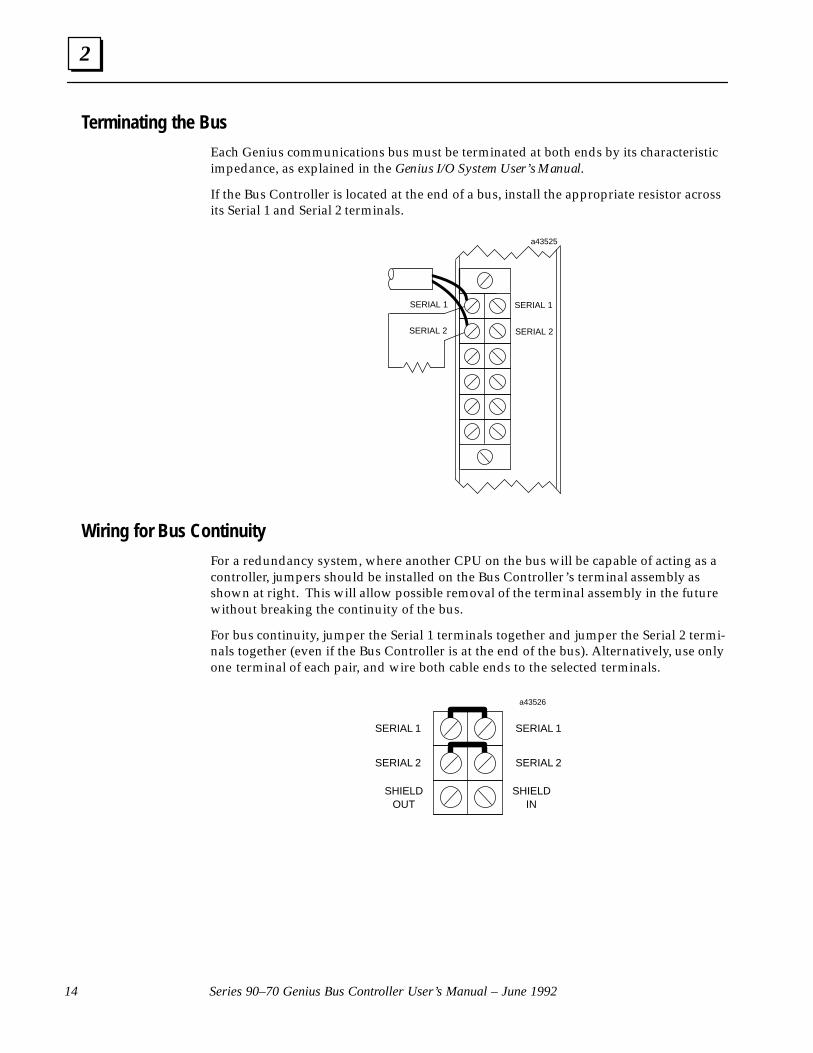
Terminating the Bus
Each Genius communications bus must be terminated at both ends by its characteristicimpedance, as explained in the Genius I/O System User’s Manual.
If the Bus Controller is located at the end of a bus, install the appropriate resistor acrossits Serial 1 and Serial 2 terminals.
ÎÎÎÎÎÎÎÎÎÎÎÎÎÎÎ
ÎÎÎÎÎ
ÎÎÎÎ
SERIAL 1
SERIAL 2
SERIAL 1
SERIAL 2
a43525
Wiring for Bus Continuity
For a redundancy system, where another CPU on the bus will be capable of acting as acontroller, jumpers should be installed on the Bus Controller’s terminal assembly asshown at right. This will allow possible removal of the terminal assembly in the futurewithout breaking the continuity of the bus.
For bus continuity, jumper the Serial 1 terminals together and jumper the Serial 2 termi-nals together (even if the Bus Controller is at the end of the bus). Alternatively, use onlyone terminal of each pair, and wire both cable ends to the selected terminals.
SERIAL 1 SERIAL 1
SERIAL 2
a43526
SERIAL 2
SHIELDOUT
SHIELDIN
ÎÎÎÎ
ÎÎÎÎ
ÎÎÎÎ
ÎÎÎÎ
3 section level 1 1figure bi level 1 table_big level 1
15
Chapter 3 Bus Controller Configuration
This chapter explains the Logicmaster 90–70 configuration steps for a Bus Controllerand its bus devices. If the configuration software being used is earlier than release 4.01,some of the features described here will not be available.
Configuration Overview
A Bus Controller and the devices on its bus must be configured in two basic, differentprocedures.
1. The Bus Controller and the devices on its bus must be configured as part of the Se-ries 90–70 PLC system using the Logicmaster 90–70 software.
2. The devices on the bus must also be configured separately. This includes:
A. Configuring I/O blocks with a Hand–held Monitor and/or Write ConfigurationCOMREQs.
B. Configuring Remote Drops using Logicmaster 90–70.
C. Configuring redundant Bus Controllers using Logicmaster 90–70.
This book only covers Logicmaster configuration of Bus Controllers.
For Additional Information, Also See:
Chapter 5, which describes Read Configuration and Write Configuration COMREQs.
Chapter 6, which describes data monitoring, distributed control, and redundant controlsystems.
The Genius Analog and Discrete Blocks Manual, which includes instructions for configuringmost I/O blocks.
The Genius I/O System and Communications Manual, which details the data that can betransferred using Read Configuration and Write Configuration COMREQs.
The Logicmaster 90–70 Software User’s Manual, which covers configuration of the entirePLC.
The Series 90–70 Remote I/O Scanner User’s Manual, which covers configuration of Re-mote Drops.
3
Series 90–70 Genius Bus Controller User’s Manual – June 199216
Configuring a Bus Controller
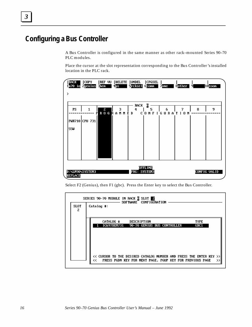
A Bus Controller is configured in the same manner as other rack–mounted Series 90–70PLC modules.
Place the cursor at the slot representation corresponding to the Bus Controller’s installedlocation in the PLC rack.
Select F2 (Genius), then F1 (gbc). Press the Enter key to select the Bus Controller.
3
17Chapter 3 Configuration
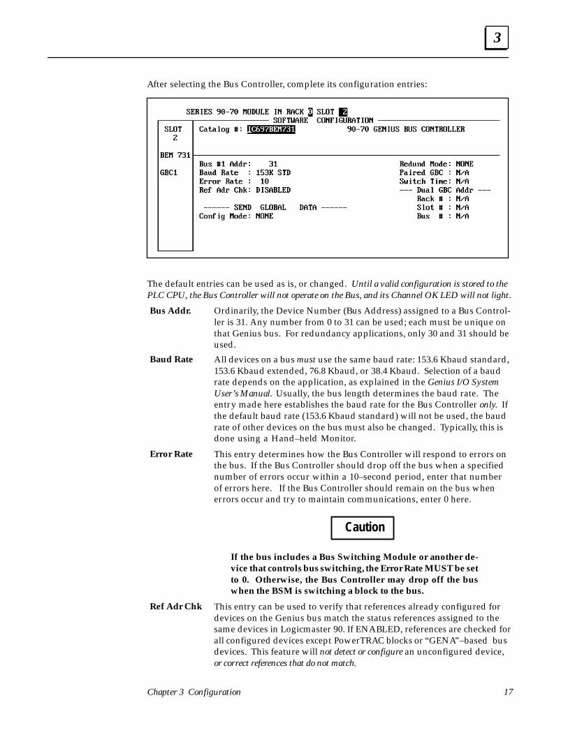
After selecting the Bus Controller, complete its configuration entries:
The default entries can be used as is, or changed. Until a valid configuration is stored to thePLC CPU, the Bus Controller will not operate on the Bus, and its Channel OK LED will not light.
Ordinarily, the Device Number (Bus Address) assigned to a Bus Control-ler is 31. Any number from 0 to 31 can be used; each must be unique onthat Genius bus. For redundancy applications, only 30 and 31 should beused.
All devices on a bus must use the same baud rate: 153.6 Kbaud standard,153.6 Kbaud extended, 76.8 Kbaud, or 38.4 Kbaud. Selection of a baudrate depends on the application, as explained in the Genius I/O SystemUser’s Manual. Usually, the bus length determines the baud rate. Theentry made here establishes the baud rate for the Bus Controller only. Ifthe default baud rate (153.6 Kbaud standard) will not be used, the baudrate of other devices on the bus must also be changed. Typically, this isdone using a Hand–held Monitor.
This entry determines how the Bus Controller will respond to errors onthe bus. If the Bus Controller should drop off the bus when a specifiednumber of errors occur within a 10–second period, enter that numberof errors here. If the Bus Controller should remain on the bus whenerrors occur and try to maintain communications, enter 0 here.
Caution
If the bus includes a Bus Switching Module or another de-vice that controls bus switching, the Error Rate MUST be setto 0. Otherwise, the Bus Controller may drop off the buswhen the BSM is switching a block to the bus.
This entry can be used to verify that references already configured fordevices on the Genius bus match the status references assigned to thesame devices in Logicmaster 90. If ENABLED, references are checked forall configured devices except PowerTRAC blocks or “GENA”–based busdevices. This feature will not detect or configure an unconfigured device,or correct references that do not match.
Bus Addr.
Baud Rate
Error Rate
Ref Adr Chk

3
Series 90–70 Genius Bus Controller User’s Manual – June 199218
Configuring Global DataThis entry determines how Global Data will be set up for the Bus Con-troller. If the Bus Controller will not send or receive Global Data, selectNONE.
If the Bus Controller will transmit Global Data, select MANUAL if youwant to specify a reference address and data length. Or select AUTO tolet the Logicmaster 90 software automatically configure the data lengthand Global Data address. See “Automatic Global Data Setup” on page19.
If you select MANUAL, the following entries appear:
Specify the beginning PLC address from which data will be transmittedon the bus. It can be from %I, %Q, %G, %R, %AI, or %AQ memory.
Also for MANUAL configuration mode, this entry specifies the amountof Global Data to be sent each bus scan.
If bit–oriented memory (%I, %Q, or %G) is selected above, this may be0 to 1024 bits. It must be a multiple of 8. If you enter a number that isnot a multiple of 8, the software will automatically adjust it upward.
If word–oriented memory (%AI, %AQ, or %R) is selected above, thismay be 0 to 64 words. If more than 64 words are selected, the Logicmas-ter 90 software automatically adjusts the length to 64 words.
The total amount of memory specified must not exceed the configuredmemory size for that memory type. For example, for the 731 CPU, themaximum value for %I memory that can be configured is 512.
This information is not used by another Series 90–70 Bus Controller. If theGlobal Data sent by this Bus Controller will be received by a Series Six�PLC or a Series Five� PLC, use this entry to configure the destinationregister address in the other PLC. Only one such destination addresscan be specified for Global Data sent by each Bus Controller; if there ismore than one Series Six and/or Series Five PLC on the bus, they mustall use the same register address for Global Data received from this BusController. For information about selecting and entering a register ad-dress for one of these PLCs, refer to the Genius I/O System User’s Manual.
NoteThe Bus Controller’s Global Data address will not be displayedon the Hand–held Monitor’s Block/Bus Status screen unlessyou enter a register address here that corresponds to the actualGlobal Data address.
If the Global Data destination is another Series 90–70 PLC, the destina-tion memory address is specified as part of that PLC’s configuration.
ConfigMode:
From Addr:
Data Length:
To (Opt):

3
19Chapter 3 Configuration
Automatic Global Data SetupSelecting AUTO configuration mode automatically assigns a Global Data address andlength to the Bus Controller. As many as 6 Bus Controllers in the same rack can easily beconfigured for Global Data in this way (additional Bus Controllers can be configured byselecting MANUAL, as described previously). If you select AUTO configuration mode,these entries appear for Global Data:
Length for Automatic Global Data
When AUTO is selected, the Logicmaster 90 software assigns a Global Data length basedupon the Bus Controller’s Device Number. The length may be either 4 bytes or 16 bytes.
Bytes of Global Data Device Numbers
416
16 through 2324 through 31
A Bus Controller’s Device Number is its bus address. The bus address chosen for a BusController may not conflict with that of any other device on its bus. Two or more BusControllers in a PLC system may use the same Device Number, providing they are ondifferent busses.
Address for Automatic Global Data
When AUTO is selected, the Logicmaster 90 software assigns %G references to GlobalData. Like the length, the starting address is based on the Bus Controller’s Device Num-ber. For the first Bus Controller configured in AUTO config. mode, the software selectsone of these %G references:
Bytes ofGlobal Data
DeviceNumber
StartingAddress
EndingAddress
44444444
1617181920212223
%G0001%G0033%G0065%G0097%G0129%G0161%G0193%G0225
%G0032%G0064%G0096%G0128%G0160%G0192%G0224%G0256
1616161616161616
2425262728293031
%G0257%G0385%G0513%G0641%G0769%G0897%G1025%G1153
%G0384%G0512%G0640%G0768%G0896%G1024%G1152%G1280
For example, if the Device Number of the first Bus Controller configured in AUTO modeis 21, the Logicmaster 90 software automatically assigns references %G0161 through%G0192, and the Global Data length is 4 bytes.

3
Series 90–70 Genius Bus Controller User’s Manual – June 199220
Configuring Additional Bus Controllers in AUTO Mode
To accommodate additional Bus Controllers in the same rack, %G memory has five moreareas, identified as %GA, %GB, %GC, %GD, and %GE. The second Bus Controller con-figured in AUTO mode is automatically assigned to %GA, the third to %GB, and so on.Within those memory areas, reference assignments and Global Data lengths are thesame for %G.
1st BusController
2nd BusController
3rd BusController
4th BusController
5th BusController
6th BusController
DeviceNum-
ber
%GAddresses
%GAddresses
%GB Addresses
%GC Addresses
%GD Addresses
%GE Addresses
16 1–32 1–32 1–32 1–32 1–32 1–32
17 33–64 33–64 33–64 33–64 33–64 33–64
18 65–96 65–96 65–96 65–96 65–96 65–96
19 97–128 97–128 97–128 97–128 97–128 97–128
20 129–160 129–160 129–160 129–160 129–160 129–160
21 161–192 161–192 161–192 161–192 161–192 161–192
22 193–224 193–224 193–224 193–224 193–224 193–224
23 225–256 225–256 225–256 225–256 225–256 225–256
24 257–385 257–385 257–385 257–385 257–385 257–385
25 386–512 386–512 386–512 386–512 386–512 386–512
26 513–640 513–640 513–640 513–640 513–640 513–640
27 641–768 641–768 641–768 641–768 641–768 641–768
28 769–896 769–896 769–896 769–896 769–896 769–896
29 897–1024 897–1024 897–1024 897–1024 897–1024 897–1024
30 1025–1152 1025–1152 1025–1152 1025–1152 1025–1152 1025–1152
31 1153–1280 1153–1280 1153–1280 1153–1280 1153–1280 1153–1280
Assigning a Bus Controller to a %G channel in AUTO mode reserves that channel; nopart of it can be assigned to another Bus Controller in the rack. If an ”external” deviceon the bus sends Global Data to the Bus Controller, that data will be placed in the samechannel, at the starting address that corresponds to the other controller’s Device Num-ber. The starting location cannot be changed but the length can, if necessary, by switch-ing to MANUAL mode. If the length is changed, it is important to be sure that the new lengthdoes not overlap a memory area being used for another device’s Global Data.
3
21Chapter 3 Configuration
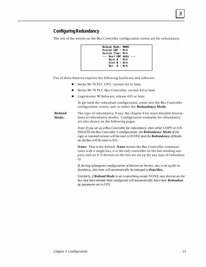
Configuring RedundancyThe rest of the entries on the Bus Controller configuration screen are for redundancy.
Use of these features requires the following hardware and software:
� Series 90–70 PLC CPU, version 4.0 or later.
� Series 90–70 PLC Bus Controller, version 4.0 or later.
� Logicmaster 90 Software, release 4.01 or later.
To get back the redundant configuration, zoom into the Bus Controllerconfiguration screen, and re–select the Redundancy Mode.
The type of redundancy, if any. See chapter 6 for more detailed descrip-tions of redundancy modes. Configuration examples for redundancyare also shown on the following pages.
Note: if you set up a Bus Controller for redundancy, then either COPY or UN-DELETE the Bus Controller’s configuration, the Redundancy Mode of thecopy or restored version will be reset to NONE and the Redundancy of blockson the bus will be reset to NO.
None: This is the default. None means the Bus Controller communi-cates with a single bus, it is the only controller on the bus sending out-puts, and no I/O devices on the bus are set up for any type of redundan-cy.
If, during subsequent configuration of devices on the bus. any is set up for re-dundancy, this item will automatically be changed to Dual Bus.
Similarly, if Redund Mode is set to anything except NONE, any devices on thebus that have already been configured will automatically have their Redundan-cy parameter set to YES.
RedundMode:
3
Series 90–70 Genius Bus Controller User’s Manual – June 199222
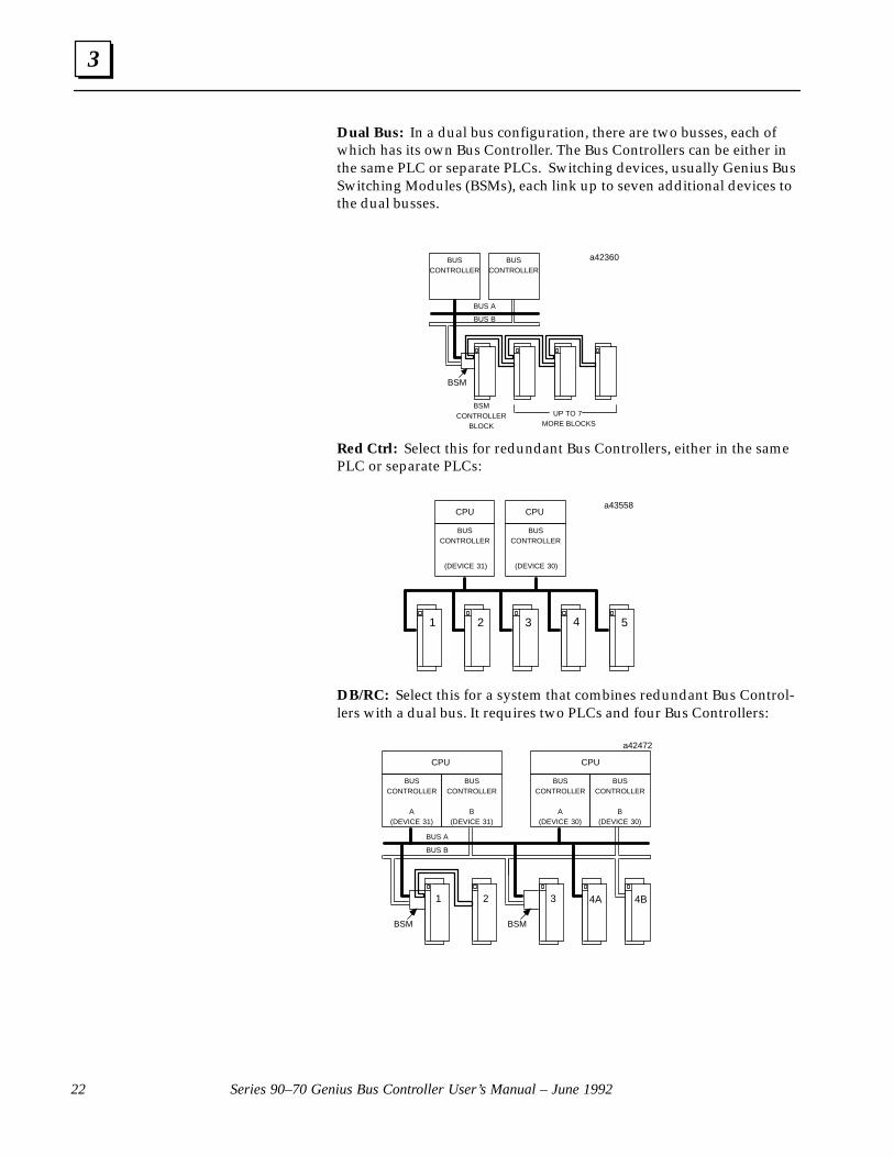
Dual Bus: In a dual bus configuration, there are two busses, each ofwhich has its own Bus Controller. The Bus Controllers can be either inthe same PLC or separate PLCs. Switching devices, usually Genius BusSwitching Modules (BSMs), each link up to seven additional devices tothe dual busses.
ÎÎÎÎÎÎÎÎÎ
a42360BUSCONTROLLER
BUSCONTROLLER
BUS A
BUS B
UP TO 7 MORE BLOCKS
BSM
BSMCONTROLLER
BLOCK
ÎÎÎÎÎÎÎÎÎ
ÎÎÎÎÎÎÎÎÎ
Red Ctrl: Select this for redundant Bus Controllers, either in the samePLC or separate PLCs:
a43558
BUSCONTROLLER
ÏÏCPU
(DEVICE 30)
4 5321
BUSCONTROLLER
ÏCPU
(DEVICE 31)
DB/RC: Select this for a system that combines redundant Bus Control-lers with a dual bus. It requires two PLCs and four Bus Controllers:
ÎÎÎÎÎÎÎÎÎÎÎÎ
a42472
BUS A
BUS B
BSM
BUSCONTROLLER
A(DEVICE 31)
CPU
BUSCONTROLLER
B(DEVICE 31)
CPU
BUSCONTROLLER
B(DEVICE 30)
BUSCONTROLLER
A(DEVICE 30)
1 2 3 4A 4B
BSM

3
23Chapter 3 Configuration
Both dual bus and dual controller redundancy use pairs of Bus Control-lers. This selection specifies the location of the other Bus Controller ofthe pair. The three choices are:
Internal: If the Redundancy Mode is either dual bus or re-dundant control and both Bus Controllers are lo-cated in the same PLC (not necessarily in the samerack), select Internal. You must also enter a DualGBC Addr (see below).
External: If the Redundancy Mode is either dual bus or re-dundant control and the other Bus Controller is inanother PLC, select External.
Int/Ext: Select this if Redund Mode is set to DB/RC. Youmust also enter a Dual GBC Addr (see below).
If, during subsequent configuration of devices on the bus, any is set up for re-dundancy, this item will automatically be changed to External.
This is the amount of time that will be allowed for switching on a dualbus. The choices are 2.5 seconds and 10 seconds. If the RedundancyMode is either Dual Bus or DB/RC and the total bus scan time on eitherbus is expected to exceed 100mS, change the Switch Time selection to 10seconds. If the Bus Controller stops receiving input data from a deviceor devices on the bus, it will wait this specified time period before de-faulting inputs or generating fault reports.
Be sure to select the same time period when configuring the devices onthe bus with a Hand–held Monitor or Write Configuration COMREQs.This determines the length of time I/O devices on the bus allow for busswitching, before defaulting their outputs.
If you selected Internal for Paired GBC, enter the location of the otherBus Controller:
For rack # and slot #, enter the rack and slot number where the otherBus Controller is located in the Series 90–70 PLC. The bus # entryshould be left as 1.
Note
When configuring a redundant system, remember to change the Loss ofIOC fault from fatal to diagnostic. Otherwise, loss of a Bus Controller willcause the PLC to shut down. (This change can be made on the Fault Cate-gories screen, during CPU configuration.)
Paired GBC:
Switch Time:
Dual GBCAddr
3
Series 90–70 Genius Bus Controller User’s Manual – June 199224
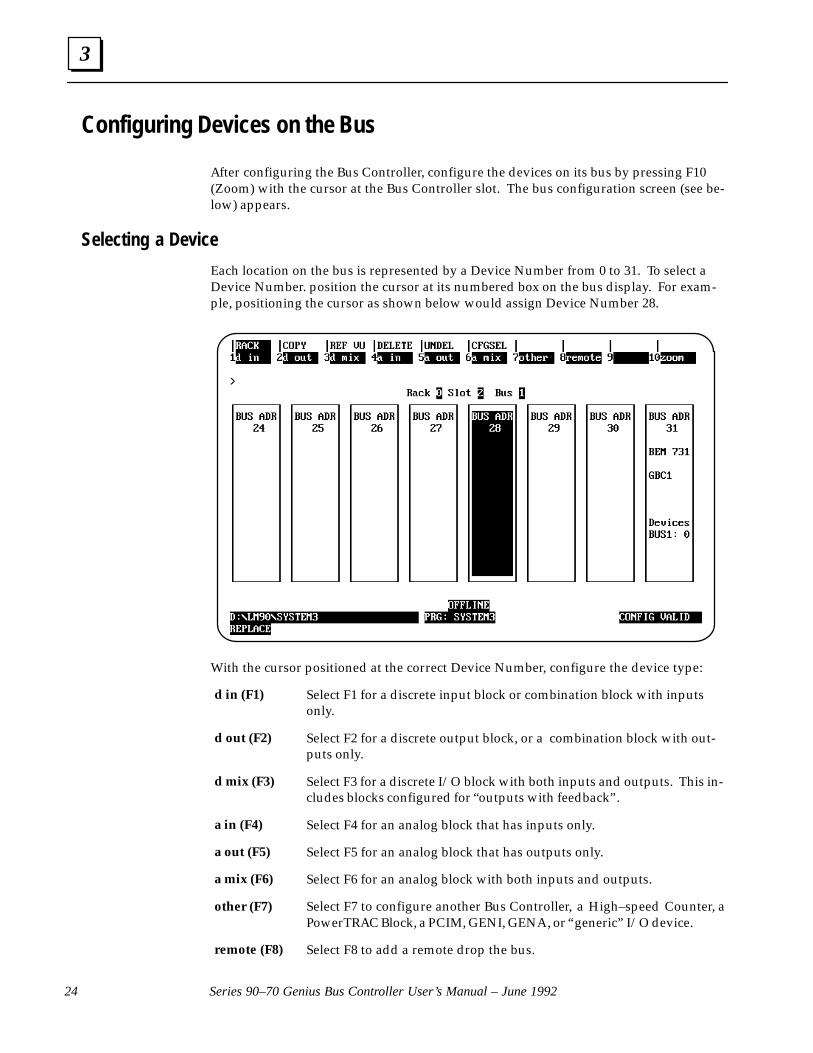
Configuring Devices on the Bus
After configuring the Bus Controller, configure the devices on its bus by pressing F10(Zoom) with the cursor at the Bus Controller slot. The bus configuration screen (see be-low) appears.
Selecting a Device
Each location on the bus is represented by a Device Number from 0 to 31. To select aDevice Number. position the cursor at its numbered box on the bus display. For exam-ple, positioning the cursor as shown below would assign Device Number 28.
With the cursor positioned at the correct Device Number, configure the device type:
Select F1 for a discrete input block or combination block with inputsonly.
Select F2 for a discrete output block, or a combination block with out-puts only.
Select F3 for a discrete I/O block with both inputs and outputs. This in-cludes blocks configured for “outputs with feedback”.
Select F4 for an analog block that has inputs only.
Select F5 for an analog block that has outputs only.
Select F6 for an analog block with both inputs and outputs.
Select F7 to configure another Bus Controller, a High–speed Counter, aPowerTRAC Block, a PCIM, GENI, GENA, or “generic” I/O device.
Select F8 to add a remote drop the bus.
d in (F1)
d out (F2)
d mix (F3)
a in (F4)
a out (F5)
a mix (F6)
other (F7)
remote (F8)

3
25Chapter 3 Configuration
Configuring I/O Blocks
Genius I/O blocks with selectable I/O configuration appear in more than one list. If adiscrete combination block will have inputs only, select it from the “D IN” (F1) list. If itwill have outputs only, select it from the “D OUT” (F2) list. If it will have both inputsand outputs, select it from the “D MIX” (F3) list. If a block is selected from the wrong list,or if its I/O type configuration is changed at a later time, a “Genius I/O Type Mismatch” errorwill be placed in the PLC Fault Table.
When a block type has been selected from the correct list, press the Enter key. A config-uration screen for that block will appear. For example, this is a configuration screen for a115 VAC 8 Circuit Grouped I/O block.
You must enter a configuration screen for each device on the bus, although you maywish to use the default references and configuration selections.
This does NOT configure the characteristics of the Genius I/O blocks themselves. Thatseparate configuration is normally done using a Hand–held Monitor, but may also bedone using Communication Request instructions in the application program. For in-formation about Communication Request instructions, see chapter 5.

3
Series 90–70 Genius Bus Controller User’s Manual – June 199226
Block Reference Address
A block’s Reference Address is the beginning reference for its inputs and outputs. Aseach block is configured, the software selects the correct memory types for that block.
For example, for a discrete block with both inputs and outputs, this address is shown inthe configuration screen as:
Ref Addr : %QInnnnn
For an analog block with both inputs and outputs, this address is shown in the configu-ration screen as:
Ref Addr : %AQInnnnn
Memor y Type
The memory type shown on the configuration screen cannot be changed. If a discretecombination block will NOT use the reference types shown (for example, if %QI isshown, but the block will be configured with a Hand–held Monitor for inputs–onlyoperation), the block has been selected from the wrong list. The memory type displayedon this screen must match the memory type selected with the Hand–held Monitor. If itdoesn’t, delete the current entry then re–select the block from the correct list.
Address
The Logicmaster programmer automatically assigns the next available reference addresswithin a memory type. If the address displayed is not appropriate, a different addresscan be entered from the keyboard. Discrete references must begin on a byte boundary(a byte boundary is a number which is one greater than a multiple of 8, for example: 9,17, or 25). If you assign a reference address out of sequence, the software will then con-tinue to increment that number for additional modules. For example, if you assigned thereference %I0401 to the first input module and it had 16 circuits, the software wouldnext assign %I0417 or %QI0417 to an input or combination block. You could change thisto a different address. A message appears when the highest available address has beenassigned, although you may have skipped lower addresses.
References for Blocks having both Discrete and Word Inputs: For certain types of Ge-nius I/O blocks (an example is the High–speed Counter block), the input data that isroutinely broadcast by the block consists of BOTH discrete and word–type data.
For such a block, the configured Reference Address represents three memory locations(in %I, %Q, and %AI memories) instead of the two (%I and %Q) assigned to other typesof blocks.
For example, a High–speed Counter block has 16 bits of input data, 16 bits of outputdata, and 15 words of calculated data. If a High–speed Counter block were configuredto use Reference Address 0049, the following memory locations would be used by theblock:
%I0049 to %I0064 for the block’s inputs%Q0049 to %Q0064 for the block’s outputs%AI0049 to %AI0063 for the block’s calculated data
3
27Chapter 3 Configuration
References for Inputs–only or Outputs–only Blocks: An Inputs–only block uses onereference in %I or %AI memory for each circuit on the block. Similarly, a block with out-puts only requires one reference in %Q or %AQ memory only.
References for Blocks with both Inputs and Outputs: A block which has both inputsand outputs uses the same number of input and output references, regardless of theblock’s actual I/O mix.
An analog block with 4 inputs and 2 outputs requires four words of analog inputmemory and four words of analog output memory. The block only uses the first twooutput words; however, the second two output words cannot be used for outputs be-cause they cannot be assigned by the configuration software. However, they can beused for internal registers in the application program.
References for Redundancy: The Series 90–70 PLC handles I/O data the same way forredundant and non–redundant systems. For any redundant Bus Controller pair in thePLC, each CPU sweep the CPU receives a one set of bus inputs and sends one set of busoutputs. The Series 90–70 PLC does not maintain two sets of references for devices thatare set up for redundancy.
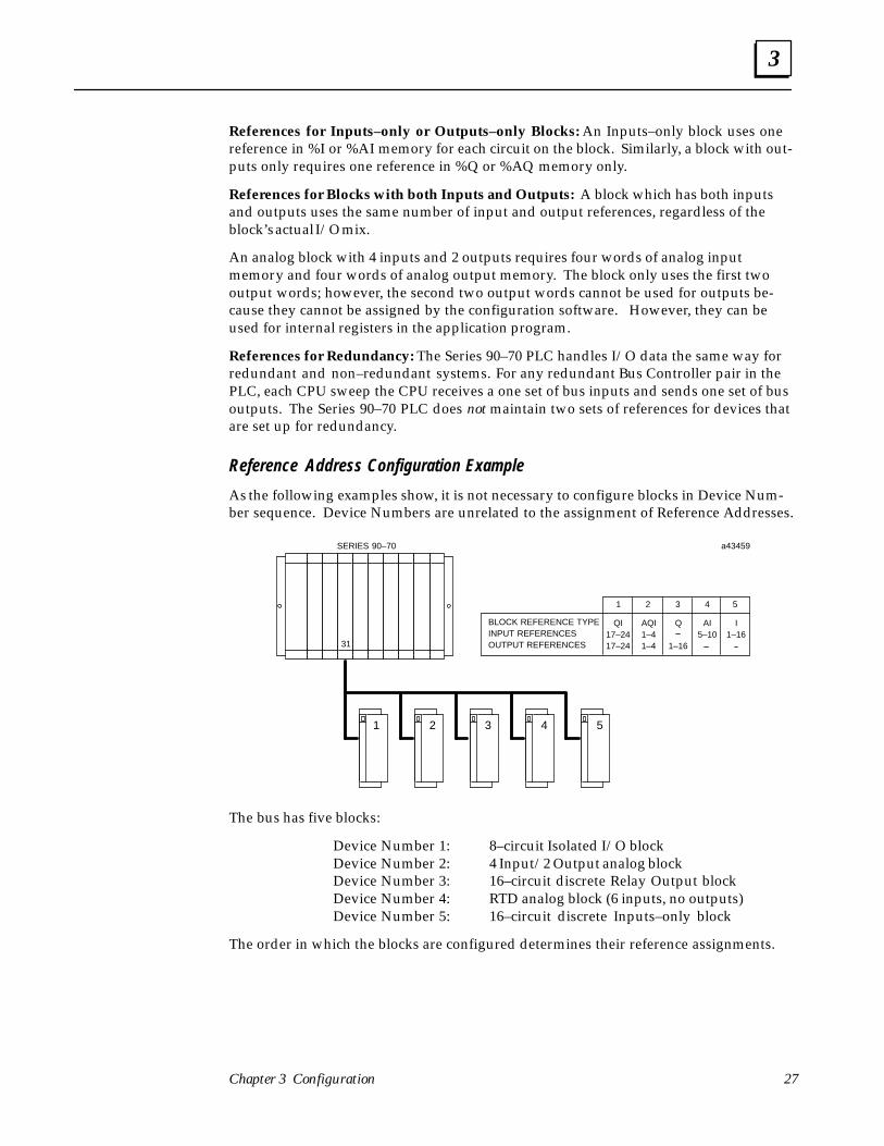
Reference Address Configuration Example
As the following examples show, it is not necessary to configure blocks in Device Num-ber sequence. Device Numbers are unrelated to the assignment of Reference Addresses.
1 2 3 4 5
BLOCK REFERENCE TYPEINPUT REFERENCESOUTPUT REFERENCES
Q
1–16
QI17–2417–24
1 2 3
AI5–10
4
AQI1–41–4
I1–16
5
a43459SERIES 90–70
31
The bus has five blocks:
Device Number 1: 8–circuit Isolated I/O blockDevice Number 2: 4 Input/2 Output analog blockDevice Number 3: 16–circuit discrete Relay Output blockDevice Number 4: RTD analog block (6 inputs, no outputs)Device Number 5: 16–circuit discrete Inputs–only block
The order in which the blocks are configured determines their reference assignments.

3
Series 90–70 Genius Bus Controller User’s Manual – June 199228
Reference Address Example Configuration 1:
Here, the first block to be configured is Device Number 5, the 16–circuit Inputs–onlyblock. The configuration software assigns to it %I0001. The second block configured isDevice Number 3, the Relay Output block. The software assigns to it %Q0001. If DeviceNumber 1, the 8–circuit Isolated I/O block, were configured next, the software wouldautomatically assign it %QI0017.
1 2 3 4 5
%I0001–%I0016FIRSTSECOND
%QI0017–%QI0024THIRD
%Q001–%QI0016
BLOCK REFERENCE TYPEINPUT REFERENCESOUTPUT REFERENCES
Q
1–16
QI17–2417–24
1 2 3
AI5–10
4
AQI1–41–4
I1–16
5
a44897SERIES 90–70
31
The assignment of %I and %Q memory would then be:
x x x x x x x x x x x x x x x x x x x x x x x x
1 16 32
x x x x x x x x x x x x x x x x x x x x x x x x
1 16 32
%I
%Q
3
29Chapter 3 Configuration
Reference Address Example Configuration 2:
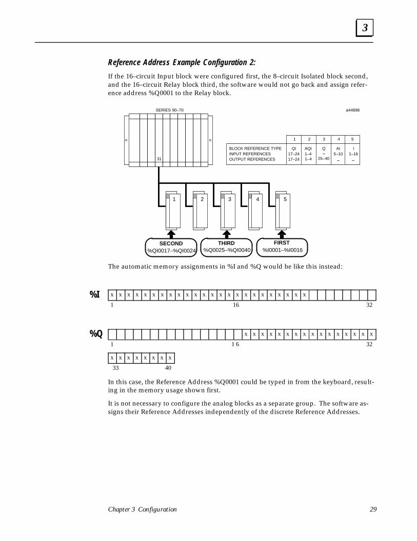
If the 16–circuit Input block were configured first, the 8–circuit Isolated block second,and the 16–circuit Relay block third, the software would not go back and assign refer-ence address %Q0001 to the Relay block.
BLOCK REFERENCE TYPEINPUT REFERENCESOUTPUT REFERENCES
1 2 3 4 5
%I0001–%I0016FIRSTSECOND
%QI0017–%QI0024THIRD
%Q0025–%QI0040
QQI17–2417–24
1 2 3
AI5–10
4
AQI1–4
I1–16
5
a44898SERIES 90–70
31 1–4 25–40
The automatic memory assignments in %I and %Q would be like this instead:
x x x x x x x x x x x x x x x x x x x x x x x x
1 16 32
x x x x x x x x x x x x x x x x
1 1 6 32
x x x x x x x x
33 40
In this case, the Reference Address %Q0001 could be typed in from the keyboard, result-ing in the memory usage shown first.
It is not necessary to configure the analog blocks as a separate group. The software as-signs their Reference Addresses independently of the discrete Reference Addresses.
%I
%Q

3
Series 90–70 Genius Bus Controller User’s Manual – June 199230
Disabling OutputsIf outputs are disabled, the Bus Controller will not send output data from the CPU to thedesignated device(s). Output Disable is not selectable for inputs–only devices. Inputs–onlyblocks are ALWAYS sent a dummy message to turn on their I/O Enabled LEDs.
It is possible for outputs to be disabled or re–enabled using Communication Requestinstructions in the application program. If this capability will be needed, then outputsshould be enabled during I/O configuration.
Ordinarily, the configuration software would be used to disable outputs that were toremain disabled. To re–enable such inputs, it would be necessary to change the configu-ration and re–store the new configuration to the PLC.
Outputs might be disabled in a system where multiple CPUs are used for distributedcontrol, or a system using the Series 90 PLC as an assigned monitoring device. Examplesare shown below.
Example
Selectively Disabling Outputs for Distributed Control of I/O Blocks: Some systems usetwo or more CPUs on the same bus for distributed control of I/O blocks. In a distrib-uted control system, each CPU sends outputs to (and receives fault reports from)certain blocks on the bus and not others. This is accomplished by selectively enab-ling or disabling outputs to the blocks.
BUSINTERFACE
MODULE
(DEVICE 30)
ÏÏÏÏ
CPU
a42485
CPU
BUSINTERFACE
MODULE
(DEVICE 31)OUTPUTS
1 2 3 4 5 6
BUSINTERFACE
MODULE
(DEVICE 7)
ÏÏÏÏÏÏ
CPU
3
31Chapter 3 Configuration
Example
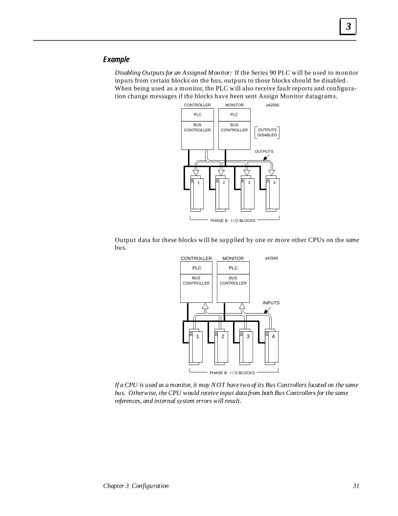
Disabling Outputs for an Assigned Monitor: If the Series 90 PLC will be used to monitorinputs from certain blocks on the bus, outputs to those blocks should be disabled.When being used as a monitor, the PLC will also receive fault reports and configura-tion change messages if the blocks have been sent Assign Monitor datagrams.
a42566
PLC
BUSCONTROLLER
BUSCONTROLLER
OUTPUTS
ÏÏPLC
1 2 3 4
CONTROLLER MONITOR
PHASE B I / O BLOCKS
OUTPUTSDISABLED
Output data for these blocks will be supplied by one or more other CPUs on the samebus.
a42565
PLC
BUSCONTROLLER
BUSCONTROLLER
INPUTS
ÏÏÏÏ
PLC
1 2 3 4
CONTROLLER MONITOR
PHASE B I / O BLOCKS
If a CPU is used as a monitor, it may NOT have two of its Bus Controllers located on the samebus. Otherwise, the CPU would receive input data from both Bus Controllers for the samereferences, and internal system errors will result.
3
Series 90–70 Genius Bus Controller User’s Manual – June 199232
Block Redundancy ConfigurationIf a block will be used in dual bus or dual controller mode, or both, set the entry for Re-dundancy to YES.
If Redundancy is set ot YES for any block on a bus, the Bus Controller must also be con-figured for a form of redundancy: dual bus, redundant control, or dual bus/redundantcontrol.
The configuration software will automatically attempt to supply a correct configurationwhen you set device Redundancy to YES:
� If the Bus Controller is configured for a Redundancy Mode of NONE, and you setthe Redundancy of any device on the bus to YES, the Bus Controller’s configurationis automatically changed to Redundancy: DUAL BUS and Paired GBC: EXTERNAL.
� If the Bus Controller is configured for a Redundancy Mode of either DUAL BUS orRedundant Control (Red Ctrl), and Paired GBC is INTERNAL, each device on thebus is automatically configured at the same bus address (Device Number) on theredundant bus, and given the same reference addresses.
If Paired GBC is set to EXTERNAL, the block is not automatically configured on theother bus of the pair.
� If the Bus Controller is configured for a Redundancy Mode of DB/RC (dual bus/re-dundant control) each device on the bus is automatically configured at the same busaddress (Device Number) on the redundant bus, and given the same reference ad-dress.
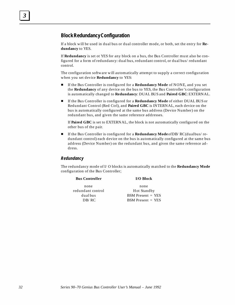
Redundancy
The redundancy mode of I/O blocks is automatically matched to the Redundancy Modeconfiguration of the Bus Controller;
Bus Controller I/O Block
none noneredundant control Hot Standby
dual bus BSM Present = YESDB/RC BSM Present = YES
3
33Chapter 3 Configuration
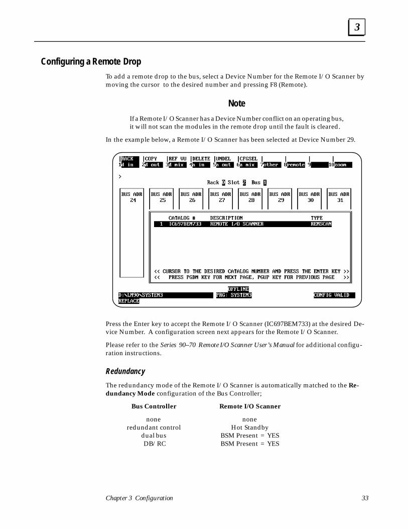
Configuring a Remote Drop
To add a remote drop to the bus, select a Device Number for the Remote I/O Scanner bymoving the cursor to the desired number and pressing F8 (Remote).
Note
If a Remote I/O Scanner has a Device Number conflict on an operating bus,it will not scan the modules in the remote drop until the fault is cleared.
In the example below, a Remote I/O Scanner has been selected at Device Number 29.
Press the Enter key to accept the Remote I/O Scanner (IC697BEM733) at the desired De-vice Number. A configuration screen next appears for the Remote I/O Scanner.
Please refer to the Series 90–70 Remote I/O Scanner User’s Manual for additional configu-ration instructions.
Redundancy
The redundancy mode of the Remote I/O Scanner is automatically matched to the Re-dundancy Mode configuration of the Bus Controller;
Bus Controller Remote I/O Scanner
none noneredundant control Hot Standby
dual bus BSM Present = YESDB/RC BSM Present = YES

3
Series 90–70 Genius Bus Controller User’s Manual – June 199234
Configuring Other Devices on the Bus
Select F7 (other) from the bus configuration screen to configure:
� Another Bus Controller on the same bus.
� A PCIM or QBIM interface module.
� A High–speed Counter Block.
� A PowerTRAC Block.
� A GENI, GENA, or generic I/O device.
After you select “other ”, a screen like this appears:
To display the names of additional devices, use PGUP or PGDN. Configuration for thedevices listed on this menu is summarized on the following pages.
3
35Chapter 3 Configuration
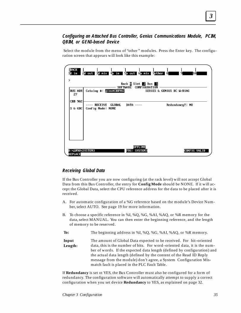
Configuring an Attached Bus Controller, Genius Communications Module, PCIM,QBIM, or GENI–based Device
Select the module from the menu of “other ” modules. Press the Enter key. The configu-ration screen that appears will look like this example:
Receiving Global Data
If the Bus Controller you are now configuring (at the rack level) will not accept GlobalData from this Bus Controller, the entry for Config Mode should be NONE. If it will ac-cept the Global Data, select the CPU reference address for the data to be placed after it isreceived.
A. For automatic configuration of a %G reference based on the module’s Device Num-ber, select AUTO. See page 19 for more information.
B. To choose a specific reference in %I, %Q, %G, %AI, %AQ, or %R memory for thedata, select MANUAL. You can then enter the beginning reference, and the lengthof memory to be reserved.
The beginning address in %I, %Q, %G, %AI, %AQ, or %R memory.
The amount of Global Data expected to be received. For bit–orienteddata, this is the number of bits. For word–oriented data, it is the num-ber of words. If the expected data length (defined by configuration) andthe actual data length (defined by the content of the Read ID Replymessage from the module) don’t agree, a System Configuration Mis-match fault is placed in the PLC Fault Table.
If Redundancy is set ot YES, the Bus Controller must also be configured for a form ofredundancy. The configuration software will automatically attempt to supply a correctconfiguration when you set device Redundancy to YES, as explained on page 32.
To:
InputLength:
3
Series 90–70 Genius Bus Controller User’s Manual – June 199236
Configuring a High–speed Counter Block
Select the High–speed Counter from the menu of “other ” modules. Press the Enter key.A configuration screen like this will appear:
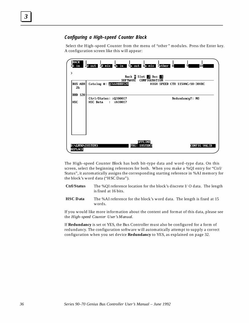
The High–speed Counter Block has both bit–type data and word–type data. On thisscreen, select the beginning references for both. When you make a %QI entry for “Ctrl/Status”, it automatically assigns the corresponding starting reference in %AI memory forthe block’s word data (“HSC Data”).
The %QI reference location for the block’s discrete I/O data. The lengthis fixed at 16 bits.
The %AI reference for the block’s word data. The length is fixed at 15words.
If you would like more information about the content and format of this data, please seethe High–speed Counter User’s Manual.
If Redundancy is set ot YES, the Bus Controller must also be configured for a form ofredundancy. The configuration software will automatically attempt to supply a correctconfiguration when you set device Redundancy to YES, as explained on page 32.
Ctrl/Status
HSC Data

3
37Chapter 3 Configuration
Configuring a PowerTRAC Block
Select the PowerTRAC Block from the menu of “other ” modules. Press the Enter key. Aconfiguration screen like the one shown below will appear.
The PowerTRAC Block has both bit–type data and word–type data. On this screen,select the beginning references for both. The required lengths are shown. You can alsoselect the default state for the block’s input data, and enable or disable CPU outputs tothe block.
If Redundancy is set ot YES, the Bus Controller must also be configured for a form ofredundancy. The configuration software will automatically attempt to supply a correctconfiguration when you set device Redundancy to YES, as explained on page 32.
If you would like more information about the content and format of PowerTRAC blockdata, please see the PowerTRAC Block User’s Manual.

3
Series 90–70 Genius Bus Controller User’s Manual – June 199238
Configuring a Generic I/O Device
A device on the bus can be configured as a “generic” I/O device. This might be done toprovide selections for “input defaults” and “outputs enabled” that are not otherwiseavailable for a given Genius product, or to configure a device that is not included in theother menus.
To configure a generic device, select GENERIC I/O from the menu of “other ” modules.Press the Enter key. A configuration screen like this will appear:
Select the beginning references and lengths for the module’s bit and word data. Thecombined lengths of bit and word inputs (%I and %AI) must exactly match the amountof data that will be sent by the device. The combined lengths of bit and word outputs(%Q and %AQ) must exactly match the amount of data that will be sent by the Bus Con-troller to the device. If the device being configured is a Bus Controller, assign it INPUTSONLY.
You can also select the default state for the device’s input data, and enable or disableCPU outputs to the device.
If Redundancy is set ot YES, the Bus Controller must also be configured for a form ofredundancy. The configuration software will automatically attempt to supply a correctconfiguration when you set device Redundancy to YES, as explained on page 32.
3
39Chapter 3 Configuration
Bus Controller Configuration StepsThe examples on the following pages show Logicmaster configuration steps for non–re-dundant and redundant Bus Controllers:
� Example 1: A non–redundant Bus Controller.
� Example 2: A Bus Controller that will use bus redundancy (dual bus), with the otherBus Controller in another PLC (typical application).
� Example 3: A Bus Controller that will use bus redundancy (dual bus), with the otherBus Controller in the same PLC (not necessarily in the same rack, however).
� Example 4: A Bus Controller that will use controller redundancy, with the other BusController in another PLC (typical application).
� Example 5: A Bus Controller that will use controller redundancy, with the other BusController in the same PLC (not necessarily in the same rack).
� Example 6: A Bus Controller that will use both dual bus and controller redundancy(typical application).

3
Series 90–70 Genius Bus Controller User’s Manual – June 199240
Bus Controller Configuration Example 1: No Redundancy
1. Select the rack and slot location forthe Bus Controller.
2. Press F2 (genius).
3. From the Catalog # screen, press F1(gbc).
4. From the Description screen, pressEnter.
5. Complete the entries on the left sideof the screen.
6. On the right side of the screen, leaveRedund mode set to NONE. Theentries below it cannot then beedited.
7. Press the ESC key to return to therack configuration screen.

3
41Chapter 3 Configuration
8. The rack configuration screen nowincludes the Bus Controller.
9. Press F10 (zoom) to go to the busconfiguration screen.
10. On the bus configuration screen, theBus Controller appears at its config-ured Bus Address, 31 in this exam-ple.
11. From here, you can configure the de-vices on the bus.
end of Example 1

3
Series 90–70 Genius Bus Controller User’s Manual – June 199242
Bus Controller Configuration Example 2:Bus Redundancy Only, Bus Controllers in Separate PLCs
1. Select the rack and slot location for theBus Controller.
2. Press F2 (genius).
3. From the Catalog # screen, press F1(gbc).
4. From the Description screen, press En-ter.
5. Complete the entries on the left sideof the screen.
6. On the right side of the screen,change Redund Mode set to DUALBUS.
7. Set Paired GBC to EXTERNAL.
8. If the bus scan time will exceed100mS, set Switch Time to 10S.
9. When you are finished with the en-tries on this screen, press the ESC keyto return to the rack configurationscreen

3
43Chapter 3 Configuration
10. The Bus Controller appears on therack configuration screen.
11. From this screen, you can zoom intothe bus configuration screen.
12. The Bus Controller appears at its con-figured Bus Address, 31 in this exam-ple.
13. To configure the bus, include all de-vices that are connected to the dualbus (via bus switching devices), as wellas any devices that are connected onlyto the portion of the bus controlled bythis Bus Controller.
Repeat these steps for the other Bus Con-troller when configuring its PLC.
end of Example 2
3
Series 90–70 Genius Bus Controller User’s Manual – June 199244
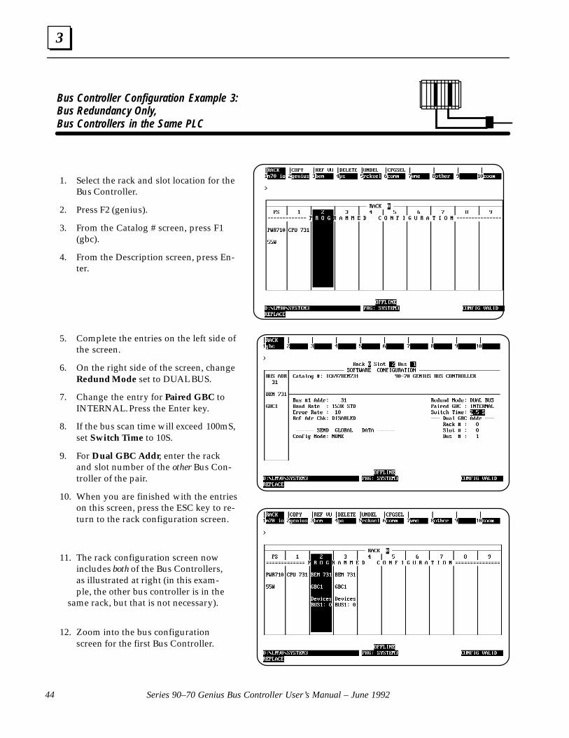
Bus Controller Configuration Example 3:Bus Redundancy Only, Bus Controllers in the Same PLC
1. Select the rack and slot location for theBus Controller.
2. Press F2 (genius).
3. From the Catalog # screen, press F1(gbc).
4. From the Description screen, press En-ter.
5. Complete the entries on the left side ofthe screen.
6. On the right side of the screen, changeRedund Mode set to DUAL BUS.
7. Change the entry for Paired GBC toINTERNAL. Press the Enter key.
8. If the bus scan time will exceed 100mS,set Switch Time to 10S.
9. For Dual GBC Addr, enter the rackand slot number of the other Bus Con-troller of the pair.
10. When you are finished with the entrieson this screen, press the ESC key to re-turn to the rack configuration screen.
11. The rack configuration screen nowincludes both of the Bus Controllers,as illustrated at right (in this exam-ple, the other bus controller is in the
same rack, but that is not necessary).
12. Zoom into the bus configurationscreen for the first Bus Controller.
3
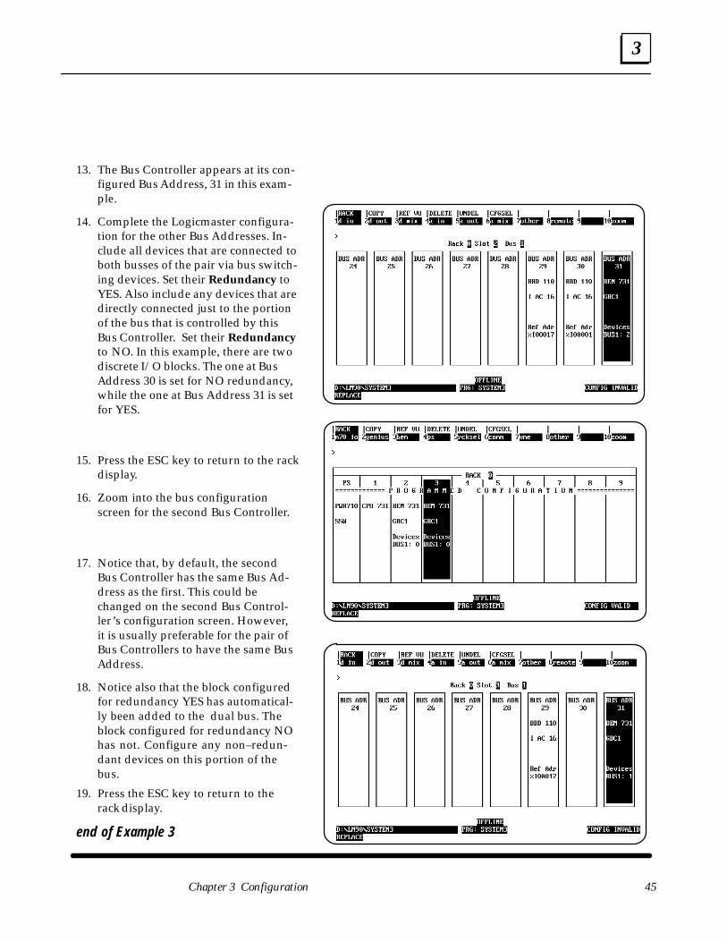
45Chapter 3 Configuration
13. The Bus Controller appears at its con-figured Bus Address, 31 in this exam-ple.
14. Complete the Logicmaster configura-tion for the other Bus Addresses. In-clude all devices that are connected toboth busses of the pair via bus switch-ing devices. Set their Redundancy toYES. Also include any devices that aredirectly connected just to the portionof the bus that is controlled by thisBus Controller. Set their Redundancyto NO. In this example, there are twodiscrete I/O blocks. The one at BusAddress 30 is set for NO redundancy,while the one at Bus Address 31 is setfor YES.
15. Press the ESC key to return to the rackdisplay.
16. Zoom into the bus configurationscreen for the second Bus Controller.
17. Notice that, by default, the secondBus Controller has the same Bus Ad-dress as the first. This could bechanged on the second Bus Control-ler’s configuration screen. However,it is usually preferable for the pair ofBus Controllers to have the same BusAddress.
18. Notice also that the block configuredfor redundancy YES has automatical-ly been added to the dual bus. Theblock configured for redundancy NOhas not. Configure any non–redun-dant devices on this portion of thebus.
19. Press the ESC key to return to therack display.
end of Example 3
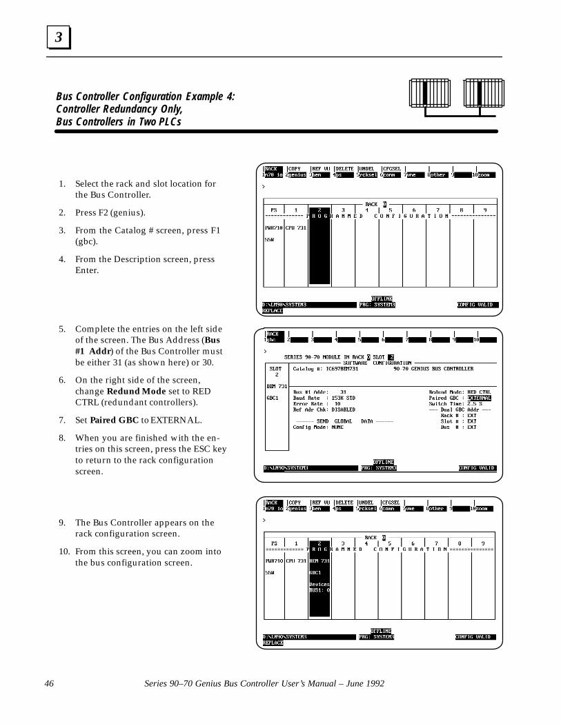
3
Series 90–70 Genius Bus Controller User’s Manual – June 199246
Bus Controller Configuration Example 4:Controller Redundancy Only, Bus Controllers in Two PLCs
1. Select the rack and slot location forthe Bus Controller.
2. Press F2 (genius).
3. From the Catalog # screen, press F1(gbc).
4. From the Description screen, pressEnter.
5. Complete the entries on the left sideof the screen. The Bus Address (Bus#1 Addr) of the Bus Controller mustbe either 31 (as shown here) or 30.
6. On the right side of the screen,change Redund Mode set to REDCTRL (redundant controllers).
7. Set Paired GBC to EXTERNAL.
8. When you are finished with the en-tries on this screen, press the ESC keyto return to the rack configurationscreen.
9. The Bus Controller appears on therack configuration screen.
10. From this screen, you can zoom intothe bus configuration screen.
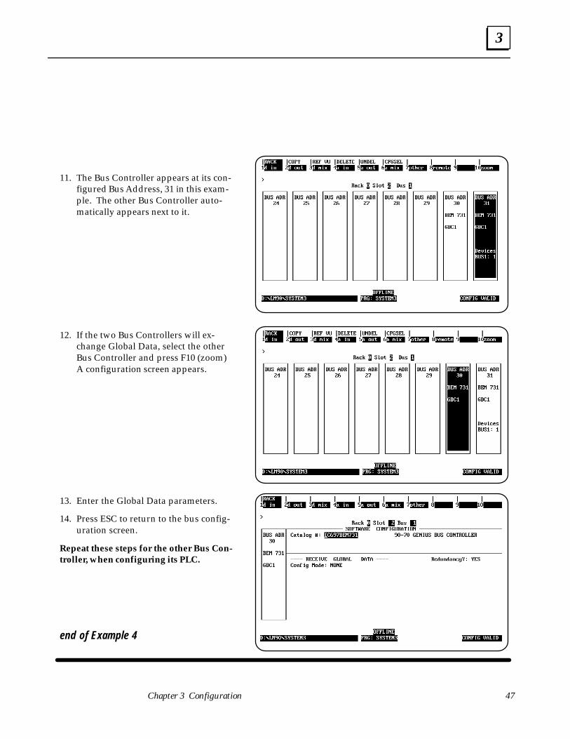
3
47Chapter 3 Configuration
11. The Bus Controller appears at its con-figured Bus Address, 31 in this exam-ple. The other Bus Controller auto-matically appears next to it.
12. If the two Bus Controllers will ex-change Global Data, select the otherBus Controller and press F10 (zoom)A configuration screen appears.
13. Enter the Global Data parameters.
14. Press ESC to return to the bus config-uration screen.
Repeat these steps for the other Bus Con-troller, when configuring its PLC.
end of Example 4

3
Series 90–70 Genius Bus Controller User’s Manual – June 199248
Bus Controller Configuration Example 5:Controller Redundancy Only, Bus Controllers in the Same PLC
1. Select the rack and slot location for theBus Controller.
2. Press F2 (genius).
3. From the Catalog # screen, press F1(gbc).
4. From the Description screen, press En-ter.
5. Complete the entries on the left sideof the screen. The Bus Address of theBus Controller must be either 31 (asshown here) or 30.
6. On the right side of the screen,change Redund mode set to REDCTRL (redundant controllers).
7. Set Paired GBC to INTERNAL.
8. For Dual GBC Addr, enter the rackand slot number of the other Bus Con-troller of the pair.
9. When you are finished with the en-tries on this screen, press the ESC keyto return to the rack configurationscreen.
10. Both of the Bus Controllers now appearon the rack configuration screen. Inthis example, they are in the samerack, as shown as right, but that is notnecessary. Each now appears as a con-figured device on the bus of the other (BUS1 : 1).
11. Zoom into the bus configurationscreen for the first Bus Controller.

3
49Chapter 3 Configuration
12. The bus configuration screen also in-cludes both of the Bus Controllers, asshown as right. From this screen, youcan configure the devices on the busfor the Bus Controller located in rack0, slot 2, which is at Bus Address 31.
13. If the two Bus Controllers will ex-change Global Data, select the otherBus Controller and press F10 (zoom)A configuration screen appears. En-ter the Global Data parameters onthe configuration screen. Press ESCto return to this bus configurationscreen.
14. Configure the rest of the bus. In thisexample, discrete blocks are placedat Bus Addresses 29 and 28. They areconfigured for redundancy YES.
15. Press ESC to return to the rack dis-play. Notice that each device config-ured for the first Bus Controller wascopied to the bus of the second(BUS1: 3).
end of Example 5

3
Series 90–70 Genius Bus Controller User’s Manual – June 199250
Bus Controller Configuration Example 6:Bus AND Controller Redundancy, Bus Controllers in Two PLCs
1. Select the rack and slot location for theBus Controller.
2. Press F2 (genius).
3. From the Catalog # screen, press F1(gbc).
4. From the Description screen, press Enter.
5. Complete the entries on the left side ofthe screen. The Device Number (Bus#1 Addr) of the Bus Controller mustbe either 31 (as shown here) or 30.
6. On the right side of the screen, changeRedund Mode to DB/RC (dual bus, re-dundant controllers).
7. Set Paired GBC to INT/EXT (internal/external).
8. If the bus scan time will exceed 100mS,set Switch Time to 10S.
9. For Dual GBC Addr, enter the rackand slot number of the other Bus Con-troller of the internal pair.
10. When you are finished with the entrieson the Bus Controller configurationscreen, press the ESC key to return tothe rack configuration screen, whichnow includes both internal Bus Con-trollers. The two external Bus Controllersare part of the second PLC’s configuration.
11. Zoom into the bus configurationscreen for the first Bus Controller.
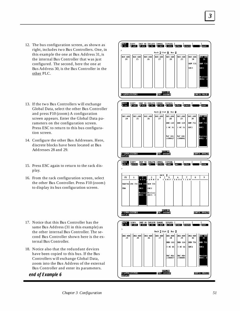
3
51Chapter 3 Configuration
12. The bus configuration screen, as shown asright, includes two Bus Controllers. One, inthis example the one at Bus Address 31, isthe internal Bus Controller that was justconfigured. The second, here the one atBus Address 30, is the Bus Controller in theother PLC.
13. If the two Bus Controllers will exchangeGlobal Data, select the other Bus Controllerand press F10 (zoom) A configurationscreen appears. Enter the Global Data pa-rameters on the configuration screen.Press ESC to return to this bus configura-tion screen.
14. Configure the other Bus Addresses. Here,discrete blocks have been located at BusAddresses 28 and 29.
15. Press ESC again to return to the rack dis-play.
16. From the rack configuration screen, selectthe other Bus Controller. Press F10 (zoom)to display its bus configuration screen.
17. Notice that this Bus Controller has thesame Bus Address (31 in this example) asthe other internal Bus Controller. The se-cond Bus Controller shown here is the ex-ternal Bus Controller.
18. Notice also that the redundant deviceshave been copied to this bus. If the BusControllers will exchange Global Data,zoom into the Bus Address of the externalBus Controller and enter its parameters.
end of Example 6
4 section level 1 1figure bi level 1 table_big level 1
53
Chapter 4 Diagnostics
This chapter describes the following diagnostics capabilities of interest in Series 90–70PLC systems that use Genius I/O and communications:
� Relevant system status references.
� Fault and No Fault Contacts, which can be used with program references or with thebuilt–in fault–locating references.
� High Alarm and Low Alarm Contacts, which will indicate when an analog referencehas reached one of its alarm limits.
� Display and clearing of Genius faults from the programmer I/O Fault Table. I/O Tablefaults related to the Bus Controller and Genius devices are listed at the end of thechapter.
For Additional Information, Also See:
Chapter 1 for an overview of Genius fault reporting.
Chapter 5, which describes the use of Read Diagnostics, Clear Circuit Faults, and ClearAll Circuit Faults COMREQs (Communication Requests).
Chapter 6 to learn how the Bus Controller’s redundancy capabilities can optionally beutilized to check its I/O and diagnostics data memory when it is not used with a dual busor as a dual controller.

4
Series 90–70 Genius Bus Controller User’s Manual – June 199254
System Status References
System status references are pre–defined locations and nicknames. They can be in-cluded in an application program to check for fault–related conditions. The followingsystem status references are of special interest for a system with a Bus Controller:
Reference Nickname Conditions Indicated When Set
%SA0009%SA0012%SA0013%SA0014%SA0017%SA0018%SA0019%SA0022%SA0023%SA0029%SB0016%SC0011%SC0013%S00010
CFG_MMLOS_RCKLOS_IOCLOS_IOMADD_RCKADD_IOCADD_IOM
IOC_FLTIOM_FLTSFT_IOC
MAX_IOCIO_FLT
IO_PRESIO_FULL
System Configuration MismatchLoss of RackLoss of Bus ControllerLoss of I/O moduleAddition of RackAddition of Bus ControllerAddition of I/O moduleBus fault or Bus Controller faultI/O module faultBus Controller software failureToo many Bus Controllers (maximum is 31)I/O fault occurredFault logged into I/O Fault TableI/O Fault Table is full
These references and their Nicknames can be used like any other type of reference. Formore information, see the Logicmaster 90 Software Reference Manual.
Example:
A PLC system includes one Bus Controller. During CPU configuration, the system statusfault LOS_IOC has been designated a diagnostic (rather than fatal) fault. LOS_IOC rep-resents loss of the Bus Controller; if this occurs, the Loss of IOC fault will be placed in theI/O Fault Table. In this example, the application program also monitors the LOS_IOCreference. If this reference is set, the contact passes power flow to an output coil, whichenergizes a warning light on an operator panel.
| LOS_IOC %Q00023|–––––||––––––––––––––––––––––––––––––––––––––––––––––––––––––––––( )–|

4
55Chapter 4 Diagnostics
Fault and No Fault Contacts
Fault and No Fault contacts can be used to detect fault or lack of fault conditions on adiscrete (%I or %Q) or analog (%AI or %AQ) reference, or they can be programmed withthe Series 90-70’s built-in fault-locating references (see below). Unless they are usedONLY with fault-locating references, fault memory for their use must be set up usingthe CPU Configuration functions of the Logicmaster 90-70 software.
A Fault contact will detect a fault in a discrete or analog input or output, or a hardwarecomponent of the system. The contact passes power flow if the reference has a fault.
Example:
| %AI0034 %M00053|–––[FAULT]–––––––––––––––––––––––––––––––––––––––––––––––––––––––( )– |
When used with a %I, %Q, %AI, or %AQ reference, a fault associated with the–[F AULT]– contact must be cleared to remove it from the fault table and stop the con-tact passing power flow. Clearing such a fault with a Hand–held Monitor does not remove itfrom the fault table or stop the contact passing power flow.
No Fault Contacts will also detect faults in discrete or analog inputs and outputs. A NoFault Contact passes power flow if its associated reference does not have a circuit fault.
Example:
| %I00167 %Q00168|–––[NOFLT]––––––––––––––––––––––––––––––––––––––––––––––––––––––––( )–|
Fault Locating References
Both Fault and No Fault contacts can be programmed with fault–locating references toidentify faults associated with system hardware. These fault references are for informa-tional purposes only. The PLC does not halt execution if one of these reference faultsoccurs. For a Genius device, the format of the fault–locating reference is M_rsbmm,where r is the rack number 0 to 7, and s is the slot number of the Bus Controller; b is thebus number, and mm is the Device Number (serial bus address) of the affected Geniusdevice (00 to 31). For example, M_46128 represents rack 4, slot 6, bus 1, module 28. Formore information about fault–locating references, please refer to the Logicmaster 90–70Software User’s Manual.
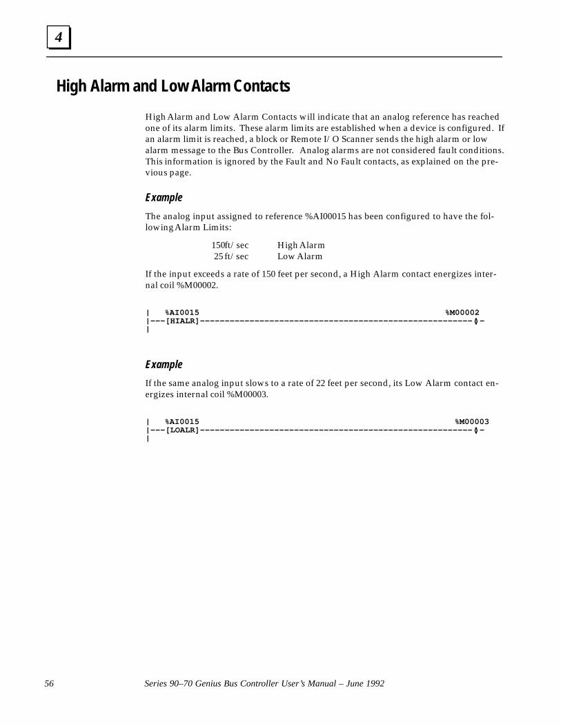
4
Series 90–70 Genius Bus Controller User’s Manual – June 199256
High Alarm and Low Alarm Contacts
High Alarm and Low Alarm Contacts will indicate that an analog reference has reachedone of its alarm limits. These alarm limits are established when a device is configured. Ifan alarm limit is reached, a block or Remote I/O Scanner sends the high alarm or lowalarm message to the Bus Controller. Analog alarms are not considered fault conditions.This information is ignored by the Fault and No Fault contacts, as explained on the pre-vious page.
Example
The analog input assigned to reference %AI00015 has been configured to have the fol-lowing Alarm Limits:
150 ft/sec High Alarm 25 ft/sec Low Alarm
If the input exceeds a rate of 150 feet per second, a High Alarm contact energizes inter-nal coil %M00002.
| %AI0015 %M00002|–––[HIALR]–––––––––––––––––––––––––––––––––––––––––––––––––––––––( )–|
Example
If the same analog input slows to a rate of 22 feet per second, its Low Alarm contact en-ergizes internal coil %M00003.
| %AI0015 %M00003|–––[LOALR]–––––––––––––––––––––––––––––––––––––––––––––––––––––––( )–|
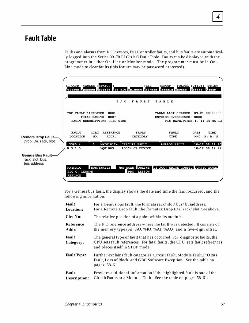
4
57Chapter 4 Diagnostics
Fault Table
Faults and alarms from I/O devices, Bus Controller faults, and bus faults are automatical-ly logged into the Series 90–70 PLC’s I/O Fault Table. Faults can be displayed with theprogrammer in either On–Line or Monitor mode. The programmer must be in On–Line mode to clear faults (this feature may be password protected).
Remote Drop Fault Drop ID#, rack, slot
Genius Bus Fault rack, slot, bus, bus address
|PROGRM |TABLES | STATUS | | |LIB |SETUP |FOLDER |UTILTY |PRINT1plcrun 2 passwd 3 plcflt 4 io flt 5 plcmem 6 blkmem 7refsiz 8 sweep 9 clear 10 zoom > I / O F A U L T T A B L E
TOP FAULT DISPLAYED: 0001 TABLE LAST CLEARED: 09–21 08:00:00 TOTAL FAULTS: 0007 ENTRIES OVERFLOWED: 0000 FAULT DESCRIPTION: OPEN WIRE PLC DATE/TIME: 10–14 10:05:13
FAULT CIRC REFERENCE FAULT FAULT DATE TIME LOCATION NO. ADDR. CATEGORY TYPE M–D H: M: S ___________ _____ _________ ___________________ ________________ _____ ________ 33#0.4 6 %AI010124 CIRCUIT FAULT ANALOG FAULT 10–12 08:12:20 0.3.1.5 %Q01009 ADD’N OF DEVICE 10–12 08:12:22
MAINPLC RUN/ENABLE 7MS SCAN ONLINE L4 ACC: WRITE CONFIG CONFIG EQUAL PLC C: LESSON PRG: LESSON REPLACE
For a Genius bus fault, the display shows the date and time the fault occurred, and thefollowing information:
For a Genius bus fault, the format is: rack/slot/bus/bus address.For a Remote Drop fault, the format is: Drop ID#/rack/slot. See above.
The relative position of a point within its module.
The I/O reference address where the fault was detected. It consists ofthe memory type (%I, %Q, %IQ, %AI, %AQ) and a five–digit offset.
The general type of fault that has occurred. For diagnostic faults, theCPU sets fault references. For fatal faults, the CPU sets fault referencesand places itself in STOP mode.
Further explains fault categories: Circuit Fault, Module Fault, I/O BusFault, Loss of Block, and GBC Software Exception. See the table onpages 58–61.
Provides additional information if the highlighted fault is one of theCircuit Faults or a Module Fault. See the table on pages 58–61.
FaultLocation:
Circ No:
Reference Addr:
FaultCategory:
Fault Type:
FaultDescription:
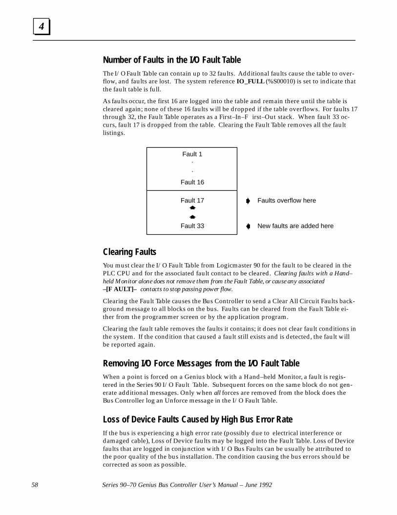
4
Series 90–70 Genius Bus Controller User’s Manual – June 199258
Number of Faults in the I/O Fault TableThe I/O Fault Table can contain up to 32 faults. Additional faults cause the table to over-flow, and faults are lost. The system reference IO_FULL (%S00010) is set to indicate thatthe fault table is full.
As faults occur, the first 16 are logged into the table and remain there until the table iscleared again; none of these 16 faults will be dropped if the table overflows. For faults 17through 32, the Fault Table operates as a First–In–F irst–Out stack. When fault 33 oc-curs, fault 17 is dropped from the table. Clearing the Fault Table removes all the faultlistings.
Fault 1
Fault 16
Fault 17
Fault 33
.
.
�
�
�
�
Faults overflow here
New faults are added here
Clearing FaultsYou must clear the I/O Fault Table from Logicmaster 90 for the fault to be cleared in thePLC CPU and for the associated fault contact to be cleared. Clearing faults with a Hand–held Monitor alone does not remove them from the Fault Table, or cause any associated–[F AULT]– contacts to stop passing power flow.
Clearing the Fault Table causes the Bus Controller to send a Clear All Circuit Faults back-ground message to all blocks on the bus. Faults can be cleared from the Fault Table ei-ther from the programmer screen or by the application program.
Clearing the fault table removes the faults it contains; it does not clear fault conditions inthe system. If the condition that caused a fault still exists and is detected, the fault willbe reported again.
Removing I/O Force Messages from the I/O Fault TableWhen a point is forced on a Genius block with a Hand–held Monitor, a fault is regis-tered in the Series 90 I/O Fault Table. Subsequent forces on the same block do not gen-erate additional messages. Only when all forces are removed from the block does theBus Controller log an Unforce message in the I/O Fault Table.
Loss of Device Faults Caused by High Bus Error RateIf the bus is experiencing a high error rate (possibly due to electrical interference ordamaged cable), Loss of Device faults may be logged into the Fault Table. Loss of Devicefaults that are logged in conjunction with I/O Bus Faults can be usually be attributed tothe poor quality of the bus installation. The condition causing the bus errors should becorrected as soon as possible.

4
59Chapter 4 Diagnostics
Fault Table Definitions
Fault Category
Diag.or
FatalIndicates Fault
TypeIndicates Fault
DescriptionIndicates
CIRCUITFAULT
D Short cir-cuit, open
DISCRETE Circuit faulton discrete
LOSS POWER Loss of user side powerCIRCUITFAULT
D Short cir-cuit, openwire, etc.
DISCRETE
FAULT
Circuit faulton discreteI/O point SHORT CIRCUIT Short in user wiringwire, etc. FAULT I/O point
OVERLOAD Sustained overcurrent
NO LOAD Very low or no current flow
OVER TEMP Switch temperature too high
SWITCH FAIL Genius “smart switch” failure
POINT FAULT Integral individual point fault
FUSE BLOWN Integral output fuse blown.
ANALOGFAULT
Fault on ana-log I/O chan-
AI LOW ALARM Input channel low alarmANALOGFAULT
Fault on ana-log I/O chan-nel AI HI ALARM Input channel high alarmnel
AI UNDER RANGE Input channel under range
AI OVER RANGE Input channel over range
OPEN WIRE Open wire detected on inputchannel
AQ UNDERRANGE
Output channel under range
AQ OVER RANGE Output channel over range
CS FEEDBACK ERR Feedback error from Current–source Analog block
GENAFAULT
Fault on aGENA
GENA CKT FLT Fault on a GENA analog ordiscrete point
LL ANALOG
Fault on alow–level
AI LOW ALARM Input channel low alarmLL ANALOGFAULT
Fault on alow–levelanalog chan-nel
AI HI ALARM Input channel high alarmFAULT analog chan-nel AI UNDER RANGE Input channel under range
AI OVER RANGE Input channel over range
OPEN WIRE Open wire detected on inputchannel
WIRING ERROR improper RTD connection orthermocouple reverse junctionfault
INTERNAL FAULT Cold junction sensor fault onthermocouple block, or inter-nal error in RTD block.
INPUT SHORT Input channel shorted
REMOTEFAULT
Fault on a Remote I/O
n/a Any fault detected by a RemoteI/O Scanner and sent to theFAULT Remote I/O
ScannerI/O Scanner and sent to thePLC.
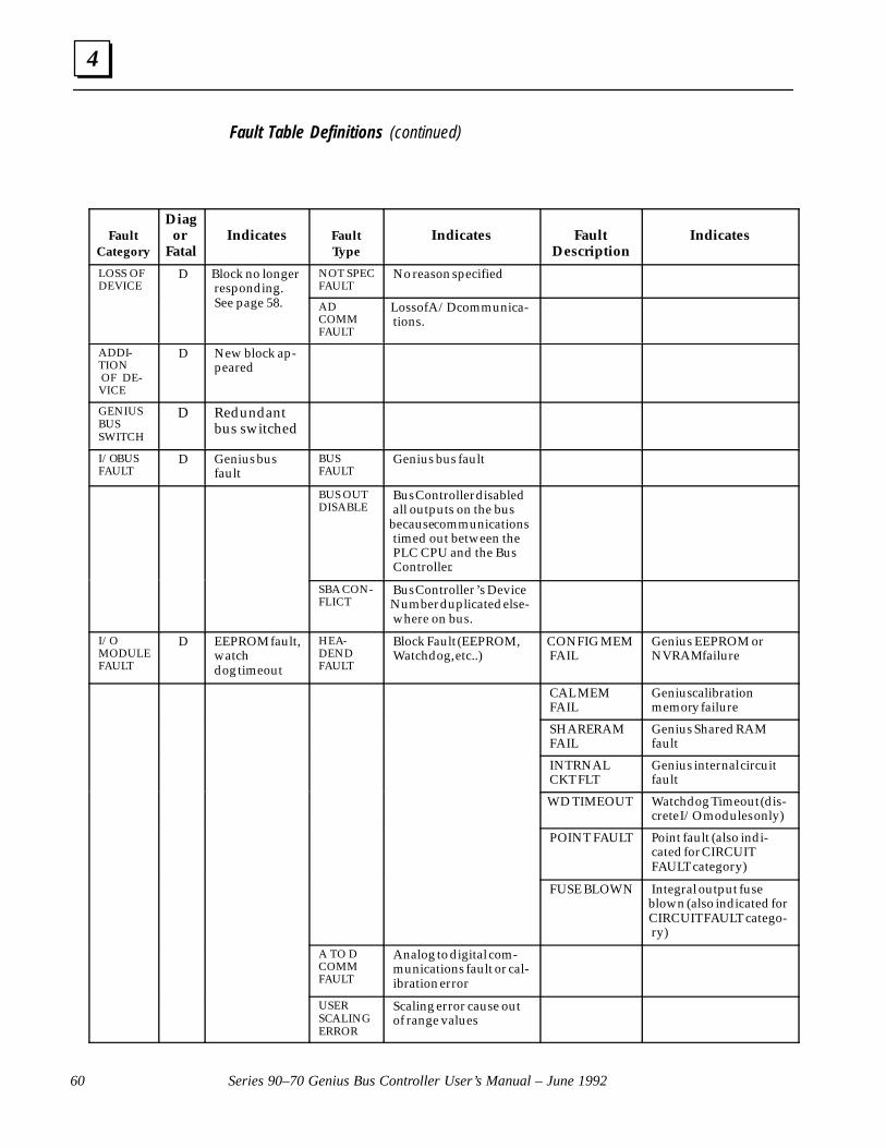
4
Series 90–70 Genius Bus Controller User’s Manual – June 199260
Fault Table Definitions (continued)
Fault Category
Diagor
FatalIndicates Fault
TypeIndicates Fault
DescriptionIndicates
LOSS OFDEVICE
D Block no longerresponding.See page 58.
NOT SPECFAULT
No reason specifiedDEVICE responding.
See page 58. ADCOMMFAULT
Loss of A/D communica-tions.
ADDI-TION OF DE-VICE
D New block ap-peared
GENIUSBUSSWITCH
D Redundantbus switched
I/O BUSFAULT
D Genius busfault
BUSFAULT
Genius bus fault
BUS OUTDISABLE
Bus Controller disabledall outputs on the bus
because communicationstimed out between thePLC CPU and the BusController.
SBA CON-FLICT
Bus Controller ’s DeviceNumber duplicated else-where on bus.
I/O MODULEFAULT
D EEPROM fault,watchdog timeout
HEA-DENDFAULT
Block Fault (EEPROM,Watchdog, etc..)
CONFIG MEMFAIL
Genius EEPROM orNVRAM failure
CAL MEMFAIL
Genius calibrationmemory failure
SHARE RAMFAIL
Genius Shared RAMfault
INTRNALCKT FLT
Genius internal circuitfault
WD TIMEOUT Watchdog Timeout (dis-crete I/O modules only)
POINT FAULT Point fault (also indi-cated for CIRCUITFAULT category)
FUSE BLOWN Integral output fuseblown (also indicated forCIRCUIT FAULT catego-ry)
A TO DCOMMFAULT
Analog to digital com-munications fault or cal-ibration error
USERSCALINGERROR
Scaling error cause outof range values

4
61Chapter 4 Diagnostics
Fault Table Definitions (continued)
Fault Category
Diag.or
FatalIndicates Fault
TypeIndicates Fault
DescriptionADDITION OF IOC
D Addition of Bus Controller
LOSS OF IOC F* Loss of or missing BusController
BUS CONTROL-LER SOFTWAREFAULT
F * Bus Controller softwarefault
FORCED CIRCUIT
D Genius I/O point forced(eg: from Hand–heldMonitor)
UNFORCEDCIRCUIT
D Last forced circuit released(eg: from Hand–heldMonitor)
EXTRA DEVICE D Found extra device on Genius bus
EXCESSIVEFAULTS
D Bus Controller hasstopped reporting faults
because too many have oc-curred
HIGH ERRORRATE
Bus Controller hasdropped off the bus for atleast 1.5 seconds.
GBC SOFTWARE EXCEPTION
D Bus Controller softwareexception
DG QUEUEFULL
Incoming datagram queueis full
EXCEPTIONexception
RW QUEUEFULL
The queue for Read/Writerequests in the Bus Con-troller is full. The requestsmay be from the Geniusbus or from COMREQs.
LP MAIL REJECTED
The low–priority mailqueue from the Bus Con-troller to the PLC is full.The response to the PLCwas lost.
* May be configured as (D)iagnostic, particularly in a redundant system.
Additional Fault InformationIf you need more information about a listing in the Fault Table, move the cursor to thatfault and press the CTRL and F keys. A number string will appear above the commandline. The Series 90–70 PLC Installation and Operation Manual (GFK–0262, version C orlater) explains how to interpret this additional fault information.
5 section level 1 1figure bi level 1 table_big level 1
63
Chapter 5 Communication Requests
This chapter explains how to use Communication Requests to:
� Pulse Test outputs on Genius blocks
� Read the configuration of a device on the bus, or the Bus Controller
� Write configuration data to a device on the bus or a Bus Controller
� Assign a device on the bus to monitor fault reports from Genius blocks
� Clear a circuit fault on the bus
� Clear all faults on the bus
� Switch a Bus Switching Module
� Read diagnostics (faults) from a device on the bus or the Bus Controller
� Read up to 64 words of data from a device on the bus
� Write up to 64 words of data from the CPU to a device on the bus
� Enable/disable all outputs from the Bus Controller to devices on the bus
� Enable/disable the Bus Controller’s ability to receive or transmit Global Data
� Enable/disable I/O fault categories
� Send a datagram to a device on the bus.
� Send a datagram to a device which then sends a reply datagram.
� Transfer an unsolicited incoming datagram from the Bus Controller to the CPU.
For Additional Information, Also See:
The Genius I/O System and Communications Manual (GEK–90486–1), which describes Ge-nius Datagrams in detail.
COMREQs and Passwords
Level 1 and 2 Logicmaster passwords, which prevent write access, cannot be used in ap-plications that include COMREQs. COMREQs require write access to return theircompletion status.

5
Series 90–70 Genius Bus Controller User’s Manual – June 199264
Programming for a Communication Request
In order to communicate with an intelligent module (such as a Bus Controller), the ap-plication program should perform the following three actions.
First, the program must supply the content of the communication. Block Moves or simi-lar program instructions can be used to place the information into CPU memory. Thiscontent is called the Command Block.
Edit content of communication
Application Program
Command Block �
CPU Memory
Second, the program must use a COMREQ instruction to perform the intended func-tion.
Sends COMREQ to Device
Application Program
� Bus Controller
Third, the program should check the status of the requested task by looking at an areaof CPU memory that is referred to as the Status Block.
Check completion of communication
Application Program
Status Block � �
CPU Memory
COMREQs should be executed sequentially. The application program should check thestatus of the previous COMREQ to a Bus Controller before sending it another one. Fail-ure to do this may result in improper operation of the Bus Controller.

5
65Chapter 5 Communication Requests
COMREQ Command Block Format
The first step in programming communications requests is to set up the contents of thecommunication. This can be done using Block Moves or similar program instructions, asshown later in this chapter.
Edit content of communication
Application Program
Command Block �
CPU Memory
Data is placed together in adjacent locations in CPU memory to form a Command Block.
Location Data
address “Data Block” Length
address + 1 Wait/No Wait Flag
address + 2 Status Pointer Memory Type
address + 3 Status Pointer Offset
address + 4 Idle Timeout Value
address + 5 Max. Communication Time
address + 6 toaddress + 70
Data Block
The length of the Command Block depends on the type of COMREQ being sent. 70words is the maximum, for a COMREQ that transfers a 128–byte datagram; most Com-mand Blocks are much shorter. A table on page 67 gives an overview of the contents ofeach type of COMREQ that may be sent to a Series 90–70 Bus Controller.
Command Block ContentsCommand Block contents are described below:
The first word of the Command Block indicates the “data block” length.This is the amount of data from [address + 6] to the end of the Com-mand Block Each type of COMREQ command has a unique Data Block,as shown in this chapter.
This must be set to 0 for No Wait.
The Status Pointer Memory Type and Offset (see below) identify thelocation of the function’s associated Status Block. The Status Block iswhere the COMREQ will return its status. If one of the bit–orientedmemories (%I or %Q) is used as the status location, its bits can be moni-tored (see page 71).
Location Data
address + 1 Status Pointer Memory
address + 2 Status Pointer offset
Length:
Wait/No WaitFlag:
Status Point-er MemoryType:
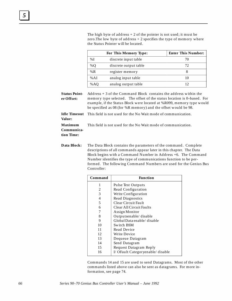
5
Series 90–70 Genius Bus Controller User’s Manual – June 199266
The high byte of address + 2 of the pointer is not used; it must bezero.The low byte of address + 2 specifies the type of memory wherethe Status Pointer will be located.
For This Memory Type: Enter This Number:
%I discrete input table 70
%Q discrete output table 72
%R register memory 8
%AI analog input table 10
%AQ analog output table 12
Address + 3 of the Command Block contains the address within thememory type selected. The offset of the status location is 0–based. Forexample, if the Status Block were located at %R099, memory type wouldbe specified as 08 (for %R memory) and the offset would be 98.
This field is not used for the No Wait mode of communication.
This field is not used for the No Wait mode of communication.
The Data Block contains the parameters of the command. Completedescriptions of all commands appear later in this chapter. The DataBlock begins with a Command Number in Address +6. The CommandNumber identifies the type of communications function to be per-formed. The following Command Numbers are used for the Genius BusController:
Command Function
123456789
10111213141516
Pulse Test OutputsRead ConfigurationWrite ConfigurationRead Diagnostics Clear Circuit Fault Clear All Circuit Faults Assign MonitorOutputs enable/disableGlobal Data enable/disable Switch BSM Read DeviceWrite DeviceDequeue DatagramSend DatagramRequest Datagram Reply I/O Fault Category enable/disable
Commands 14 and 15 are used to send Datagrams. Most of the othercommands listed above can also be sent as datagrams. For more in-formation, see page 74.
Status Point-er Offset:
Idle TimeoutValue:
MaximumCommunica-tion Time:
Data Block:
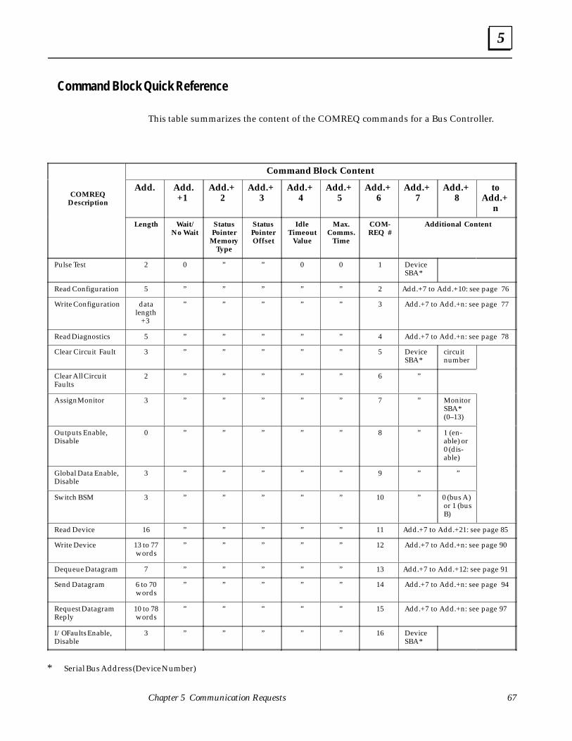
5
67Chapter 5 Communication Requests
Command Block Quick Reference
This table summarizes the content of the COMREQ commands for a Bus Controller.
Command Block Content
COMREQ Description
Add. Add.+1
Add.+2
Add.+3
Add.+4
Add.+5
Add.+6
Add.+7
Add.+8
toAdd.+
n
Length Wait/No Wait
StatusPointer
MemoryType
StatusPointerOffset
IdleTimeout
Value
Max.Comms.
Time
COM-REQ #
Additional Content
Pulse Test 2 0 ” ” 0 0 1 DeviceSBA*
Read Configuration 5 ” ” ” ” ” 2 Add.+7 to Add.+10: see page 76
Write Configuration datalength
+3
” ” ” ” ” 3 Add.+7 to Add.+n: see page 77
Read Diagnostics 5 ” ” ” ” ” 4 Add.+7 to Add.+n: see page 78
Clear Circuit Fault 3 ” ” ” ” ” 5 DeviceSBA*
circuitnumber
Clear All CircuitFaults
2 ” ” ” ” ” 6 ”
Assign Monitor 3 ” ” ” ” ” 7 ” MonitorSBA*(0–13)
Outputs Enable,Disable
0 ” ” ” ” ” 8 ” 1 (en-able) or0 (dis-able)
Global Data Enable,Disable
3 ” ” ” ” ” 9 ” ”
Switch BSM 3 ” ” ” ” ” 10 ” 0 (bus A)or 1 (busB)
Read Device 16 ” ” ” ” ” 11 Add.+7 to Add.+21: see page 85
Write Device 13 to 77words
” ” ” ” ” 12 Add.+7 to Add.+n: see page 90
Dequeue Datagram 7 ” ” ” ” ” 13 Add.+7 to Add.+12: see page 91
Send Datagram 6 to 70words
” ” ” ” ” 14 Add.+7 to Add.+n: see page 94
Request DatagramReply
10 to 78words
” ” ” ” ” 15 Add.+7 to Add.+n: see page 97
I/O Faults Enable,Disable
3 ” ” ” ” ” 16 DeviceSBA*
* Serial Bus Address (Device Number)

5
Series 90–70 Genius Bus Controller User’s Manual – June 199268
The COMREQ Instruction
After supplying the content of the communication in the Command Block, the applica-tion program uses a COMREQ instruction to request communications with the Bus Con-troller.
Sends COMREQ to Device
Application Program
� Bus Controller
COMREQ Inputs and Outputs
The COMREQ instruction has four inputs and two outputs:
COMM
REQ
IN FT
SYSID
TASK
– function OK (logic)
– function faulted (logic)Pointer to the Command Block –
Location of the Bus Controller –
Must be 1 for the Bus Controller –
(enable) –
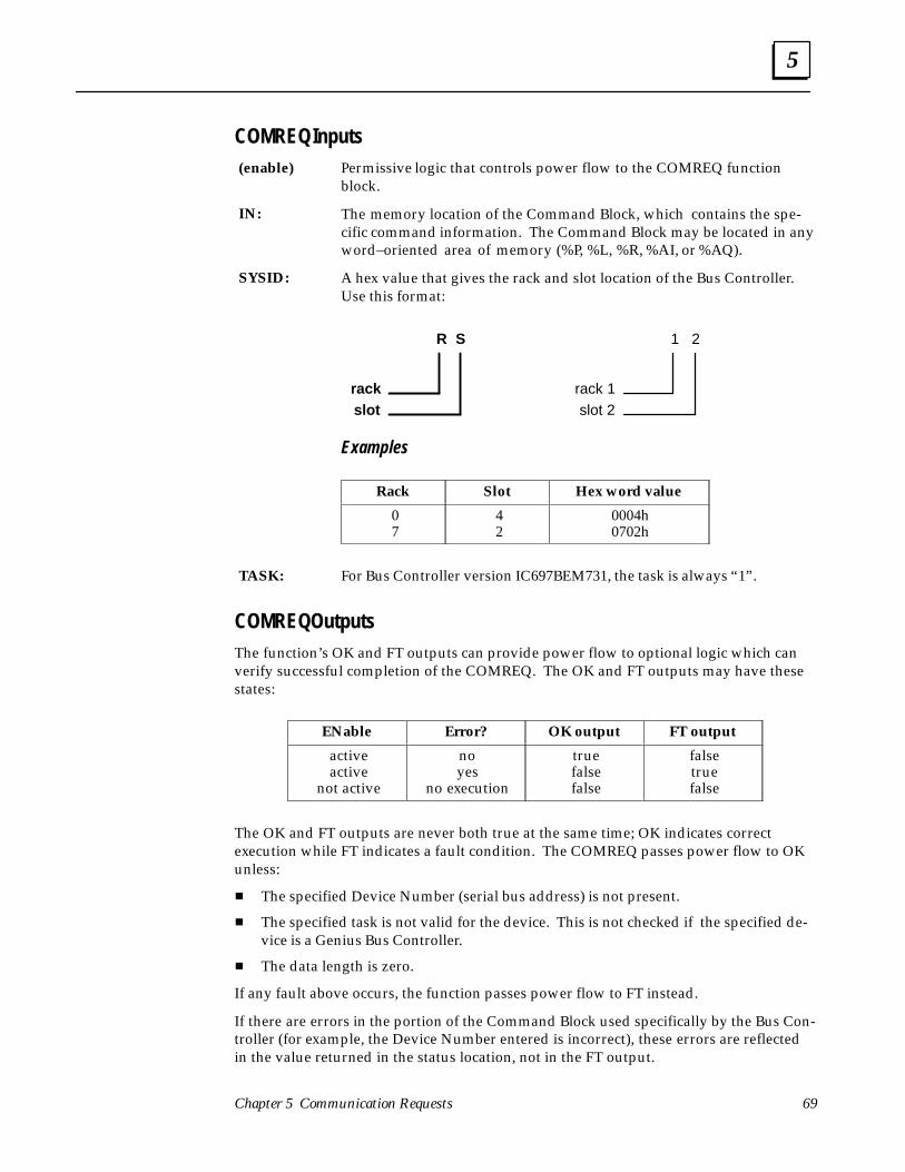
5
69Chapter 5 Communication Requests
COMREQ InputsPermissive logic that controls power flow to the COMREQ functionblock.
The memory location of the Command Block, which contains the spe-cific command information. The Command Block may be located in anyword–oriented area of memory (%P, %L, %R, %AI, or %AQ).
A hex value that gives the rack and slot location of the Bus Controller.Use this format:
R S
rackslot
1 2
rack 1slot 2
Examples
Rack Slot Hex word value
07
42
0004h0702h
For Bus Controller version IC697BEM731, the task is always “1”.
COMREQ OutputsThe function’s OK and FT outputs can provide power flow to optional logic which canverify successful completion of the COMREQ. The OK and FT outputs may have thesestates:
ENable Error? OK output FT output
activeactive
not active
noyes
no execution
truefalsefalse
falsetruefalse
The OK and FT outputs are never both true at the same time; OK indicates correctexecution while FT indicates a fault condition. The COMREQ passes power flow to OKunless:
� The specified Device Number (serial bus address) is not present.
� The specified task is not valid for the device. This is not checked if the specified de-vice is a Genius Bus Controller.
� The data length is zero.
If any fault above occurs, the function passes power flow to FT instead.
If there are errors in the portion of the Command Block used specifically by the Bus Con-troller (for example, the Device Number entered is incorrect), these errors are reflectedin the value returned in the status location, not in the FT output.
(enable)
IN:
SYSID:
TASK:
5
Series 90–70 Genius Bus Controller User’s Manual – June 199270
COMREQ Status Block
When the Bus Controller receives the communication from the CPU, it returns its cur-rent status to the CPU, at the memory location reserved for that purpose. This memorylocation is referred to as the “Status Block”. Possible status values that may be returnedare listed on the next page.
When a command is complete, the Bus Controller writes any resulting data into the areadesignated in the command, and sets the status to Complete (4).
Note
Because COMREQs require write access to return their status, level 1 and2 Logicmaster software passwords, which prevent write access, cannot beused with COMREQs.
If one of the bit–oriented memories (%I or %Q) is used as the status location, its bits canbe monitored. These bits correspond to the binary values listed below. For example, if%I048 were selected as the beginning location, reference %I050 would be set to 1 eachtime the COMREQ completed successfully.
Clearing the Status BlockCOMREQs to the Bus Controller should be executed sequentially. Before sending aCOMREQ to the Bus Controller, the application program should check the status of anyprevious COMREQ to that Bus Controller.
Check completion of communication
Application Program
Status Block � �
CPU Memory
When the previous COMREQ has completed, the program should set the Status Block toa value not in the list on the next page. Establishing this initial condition allows the pro-gram to differentiate between the result of an earlier command and the currently–executing command.

5
71Chapter 5 Communication Requests
Contents of the Status Block
The Status Block is two words of memory to which the Bus Controller returns the statusof the COMREQ.
The lower word is used for general information about the execution of the COMREQ:
VALUEDESCRIPTIONdecimal
(word)binary (bit) DESCRIPTION
0148
163264
128256512
10242048
MSB 000000000000000000000001000000000010000000001000000000010000000000100000000001000000000010000000000100000000001000000000010000000000100000000000
Bus Controller busyCommand not accepted, Bus Controller busy with previous request
Command completed successfullyCommand terminated due to syntax error Command terminated due to data errorCommand terminated due to suspended activity on bus No data to transferCommand not supported by target deviceOnly No Wait commands may be sent to the target deviceMaximum Comms. Time must be greater than or equal to 5mSText buffer invalid in wait mode Device did not accept the message, or timed out.
The upper word of the status location provides additional status information.
VALUEdecimal(word)
DESCRIPTION
11215171
101102121141142143144201202203204205206207208209210211212213
Non–discrete block specified for Pulse TestNon–I/O device specified for Read ConfigurationInvalid circuit numberNon–controller device specified for Assign MonitorSwitch BSM – device not BSMSwitch BSM – bus position greater than 1P and L access not availableFunction code greater than 111Sub function code greater than 255Priority greater than 1 Datagram length greater than 134Invalid Device Number (greater than 31, but not 255)Incorrect length for the command typeDevice Number not configured or not active
Previous No Wait command in progress; current No Wait command not acceptedInvalid status pointer location specified Command number is out of rangeSubcommand code is out of rangeOnly partial data transferredDevice Number 255 not allowed for this command Command specified is not valid for Genius Bus ControllerCommand specified is only valid for controller devices Command specified is not supported by the device to which it was sent Invalid Alarm Enable/Disable mask
5
Series 90–70 Genius Bus Controller User’s Manual – June 199272
Programming Examples
The following example shows how a Communication Request can be used to clear acircuit fault on point 4 of a Genius I/O block whose Device Number is 20.
| _____ _____ _____| FST_SCN | | | | | | |–––| |–––––––––––|MOVE |–––––––––––––––––|MOVE |–––––––––––––––––|MOVE | | | UINT| | UINT| |UINT || | | | | | || CONST–|IN Q|–%R00100 CONST–|IN Q|–%R00101 CONST–|IN Q|–%R00102| 00003 | | 00000 | | 00008 | || | LEN | | LEN | | LEN || | 001 | | 001 | | 001 || |_____| |_____| |_____|| _____ _____ _____| FST_SCN | | | | | ||–––| |–––––––––––|MOVE |–––––––––––––––––|MOVE |–––––––––––––––––|MOVE || | UINT| | UINT| | UINT|| | | | | | || CONST–|IN Q|–%R00103 CONST–|IN Q|–%R00104 CONST–|IN Q|–%R00105| 00098 | | 00000 | | 00000 | || | LEN | | LEN | | LEN || | 001 | | 001 | | 001 || |_____| |_____| |_____|| _____ _____ _____| FST_SCN | | | | | ||–––| |–––––––––––|MOVE |–––––––––––––––––|MOVE |–––––––––––––––––|MOVE || | UINT| | UINT| | UINT|| | | | | | || CONST–|IN Q|–%R00106 CONST–|IN Q|–%R00107 CONST–|IN Q|–%R00108| 00005 | | 00020 | | 00004 | || | LEN | | LEN | | LEN || | 001 | | 001 | | 001 || |_____| |_____| |_____||| _____ | %Q00128 | | %Q00129|–––| |–––|COMM |–––––––––––––––––––––––––––––––––––––––––––––––––––––––––––(S)–| | REQ | | | | %Q00130| %R00100–|IN FT|–––––––––––––––––––––––––––––––––––––––––––––––––––––––––––(S)–| | | | | || CONST –|SYSID| | 00002 | | | | | | CONST |TASK | | 00001 | | | |_____|
This example logic uses a series of Move instructions to assemble the data that will beused as inputs for the Communication Request instruction, and for its associated Com-mand Block.
Address Contents Value Description
%R100%R101%R102%R103%R104%R105%R106%R107%R108
Command lengthWait/No Wait FlagStatus Pointer MemoryStatus Pointer OffsetIdle Timeout ValueMax.Communication TimeCommand NumberDevice NumberPoint to be cleared
30
0898005
204
No waitSelects %R memory typeAddress in %R memory (%R099)Unused (No Wait selected)Unused (No Wait selected)Clear Circuit FaultDevice Number of the blockClear 4th point on block (For a COMREQ, pointsare numbered starting at 1 (not 0). If this were adatagram message instead of a COMREQcommand, points would begin at 0).

5
73Chapter 5 Communication Requests
The Move instructions are executed during the first CPU sweep, when the special refer-ence FST_SCN is true. This assures that the Communication Request will never beexecuted with incomplete or incorrect parameters.
The example uses the reference %Q128 as a permissive to the Communication Request.Output %Q129 is set if the Communication Request executes successfully. If it does not,output %Q130 is set instead. For the Communication Request, failure might occur if theCommunication Request has been set up incorrectly, or for any of the other errors speci-fied in the beginning of this chapter. A fault output is NOT caused by failure to receive areply. This must be detected from the contents of the status location.
| _____| %Q00128 | | %Q00129|–––| |–––|COMM |–––––––––––––––––––––––––––––––––––––––––––––––(S)–| | REQ || | | %Q00130| %R00100–|IN FT|–––––––––––––––––––––––––––––––––––––––––––––––(S)–| | || | || CONST –|SYSID|| 00002 | || | || CONST –|TASK || 00001 | || |_____||
Another way to assemble the data for the example Command Block would be to use aBlock Move instruction:
| _____ _____| FST_SCN | | | ||–––| |–––|BLKMV|––––––––––––––––|BLKMV|–| | INT| | INT|| | | | || CONST –|IN1 Q|–%R0100 CONST –|IN1 Q|–%R0107| +00002 | | +0020 | || CONST –|IN2 | CONST –|IN2 || +00000 | | +0004 | || CONST –|IN3 | CONST –|IN3 || +00008 | | +0000 | || CONST –|IN4 | CONST –|IN4 || +00098 | | +0000 | || CONST –|IN5 | CONST –|IN5 || +00000 | | +0000 | || CONST –|IN6 | CONST –|IN6 || +00000 | | +0000 | || CONST –|IN7 | CONST –|IN7 || +00005 | | +0000 | || |_____| |_____||
5
Series 90–70 Genius Bus Controller User’s Manual – June 199274
COMREQs and Datagrams
The table below lists datagrams with their Subfunction Codes, shows the best ways tosend datagrams, and explains what happens to datagrams received from other devices.
Datagram (hex code) Ways to Send It How Incoming Datagram is HandledRead ID (00) COMREQ 15 (Request Datagram Reply) * Bus Controller replies automatically to Read ID datagram
received from bus device.
Read ID Reply (01) (Sent automatically) Handled automatically if COMREQ 15 was used to send ReadID datagram. *
Read Configuration (02) COMREQ 2 (Read Configuration) COMREQ 15 (Request Datagram Reply) *
Bus Controller ignores it.
Read Configuration Reply(03)
(Sent automatically) Handled automatically if COMREQ 2 or 15 was used to sendRead Configuration datagram. *
Write Configuration (04) COMREQ 3 (Write Configuration)COMREQ 14 (Send Datagram)
Bus Controller ignores it.
Assign Monitor (05) COMREQ 7 (Assign Monitor)COMREQ 14 (Send Datagram)
Bus Controller ignores it.
Begin Packet Sequence(06) COMREQ 14 (Send Datagram) Bus Controller ignores it.
End Packet Sequence (07) COMREQ 14 (Send Datagram) Bus Controller ignores it.
Read Diagnostics (08) COMREQ 4 (Read Diagnostics) COMREQ 15 (Request Datagram Reply) *
Bus Controller replies automatically.
Read Diagnostics Reply(09)
(Sent automatically) Handled automatically if COMREQ 4 or 15 was used to sendRead Diagnostics datagram. *
Write Point (0B) COMREQ 14 (Send Datagram) Bus Controller ignores it.
Read Block I/O (0C) COMREQ 15 (Request Datagram Reply) * Bus Controller ignores it.
Read Block I/O Reply (0D) (Sent automatically) Handled automatically if COMREQ 15 was used to send ReadBlock I/O datagram. *
Report Fault (0F) (Sent automatically) Received from bus devices; Bus Controller automaticallyplaces the fault in the Fault Table.
Pulse Test (10) COMREQ 1 (Pulse Test) * Bus Controller ignores it.
Pulse Test Complete (11) (Sent automatically) Handled automatically if COMREQ 1 was used to send PulseTest datagram. *
Clear Circuit Faults (12) COMREQ 5 (Clear Circuit Fault)COMREQ 14 (Send Datagram)
Bus Controller ignores it.
Clear All Circuit Faults(13)
COMREQ 6 (Clear All Ckt Faults)COMREQ 14 (Send Datagram)
Bus Controller ignores it.
Switch BSM (1C) COMREQ 10 (Switch BSM)COMREQ 14 (Send Datagram)
Bus Controller ignores it.
Read Device (1E) COMREQ 11 (Read Device)COMREQ 15 (Request Datagram Reply)
Bus Controller automatically sends reply.
Read Device Reply (1F) (Sent automatically) Handled automatically if COMREQ 11 or 15 was used to sendRead Device datagram. *
Write Device (20) COMREQ 12 (Write Device)COMREQ 14 (Send Datagram)
Bus Controller processes automatically.
Read Data (27) COMREQ 15 (Request Datagram Reply) Bus Controller ignores it.
Read Data Reply (28) (Sent automatically) Handled automatically if COMREQ 15 was used to send ReadData datagram. *
Write Data (29) COMREQ 14 (Send Datagram) Bus Controller ignores it.
Read Map (2A) COMREQ 15 (Request Datagram Reply) Bus Controller ignores it.
Read Map Reply (2B) (Sent automatically) Handled automatically if COMREQ 15 was used to send ReadMap datagram.
Write Map (2C) COMREQ 14 (Send Datagram) Bus Controller ignores it.
* All datagrams can be sent using COMREQ 14 (Send Datagram). If COMREQ 14 is used to send a datagram that has a reply, COMREQ13 (Dequeue Datagram) must also be used, to obtain the reply from the Bus Controller’s queue of unsolicited incoming datagrams

5
75Chapter 5 Communication Requests
COMREQ #1: Pulse Test Command
The Pulse Test command causes the Bus Controller to send a normal–priority Pulse Testdatagram.
Pulse testing is used to verify the operation of outputs on discrete Genius I/O blocks. Itchecks whether the outputs will change state, and whether output circuits (wires, powersources, loads) will start or stop current flow. Any circuit faults generated by pulse testsare reported through the normal Report Fault message. Pulse testing is recommendedfor blocks that seldom change state. It is typically done once per hour, or once per shift;it should not be done more often than once per minute. Pulse testing provides assur-ance that when needed, an output will operate correctly. Blocks that control outputsthat change state frequently do not need to be pulse tested. Pulse testing does not pro-vide enough energy to activate mechanical devices such as motor starters, relays, or sole-noid valves, but may change the state of a very small load. If appropriate, blocks can beconfigured (with the Hand–held Monitor or via a Write Configuration command) toignore a Pulse Test datagram. Pulse testing can also be done using a Hand–held Moni-tor.
Command Block Format for the Pulse Test Command
Address: Command Length 2
Address +1: No Wait 0
Address +2: Status Block memorytype
70 (%I), 72 (%Q), 8 (%R), 10 (%AI), or 12 (%AQ)
Address +3: Status Block offset Beginning address for the COMREQ status.
Address +4: Idle timeout value 0
Address +5: Max. communicationstime
0
Address +6: Command number 1
Address +7: Device Number 0 – 31. Or enter 255 to Pulse Test all discrete blocks.

5
Series 90–70 Genius Bus Controller User’s Manual – June 199276
COMREQ #2: Read Configuration Command
The Read Configuration command is used to request configuration data from any blockon the bus. It causes the Bus Controller to send a normal–priority Read Configurationdatagram to the indicated block. After receiving the request, the block returns its config-uration data to the Bus Controller in 16–byte increments. When the Bus Controller hasreceived all the configuration data, it transfers the data to the memory location specifiedin the Command Block. Because configuration data consists of both bit–type and byte–type portions, it is best to place it in word memory, then move the bit–oriented data tobit memory (%M or %T is recommended). Contents of Read Configuration Reply mes-sages for I/O blocks are shown in the Genius I/O System User’s Manual.
Before a block can be sent this command, its Device Number (serial bus address) must beset up using the Logicmaster 90 configuration software. In addition, the block musthave had its Device Number entered using a Hand–held Monitor.
Command Block for the Read Configuration Command
Address: Command Length 5
Address +1: No Wait 0
Address +2: Status Block memorytype
70 (%I), 72 (%Q), 8 (%R), 10 (%AI), or 12 (%AQ)
Address +3: Status Block offset Beginning address for the COMREQ status.
Address +4: Idle timeout value 0
Address +5: Max. communica-tions time
0
Address +6: Command number 2
Address +7: Device Number 0 – 31.
Address +8: Maximum datamemory length.May represent eitherbits or words (de-pends on thememory type se-lected below).
18 words (288 bits): any discrete block13 words (208 bits): 16 Circuit AC Input block42 words (672 bits): Analog blocks (4 inputs/2 outputs)42 words (672 bits): RTD or Thermocouple blocks42 words (672 bits): 6–input Analog blocks35 words (560 bits): High–speed Counter13 words (208 bits): PowerTRAC Block
If the length of data returned by the device exceeds thislength, the Bus Controller writes as much data as pos-sible to the PLC CPU and returns a data error to theCOMREQ status location.
If the same COMREQ will be used to read configurationdata from more than one type of block (for example, in asubroutine), be sure to allow enough length to accommo-date the largest amount of data that might be returned.
Address +9: Memory type of thelocation where theBus Controller willplace the data in theCPU.
70 (%I), 72 (%Q), 8 (%R), 10 (%AI), or 12 (%AQ).
Address +10: Memory offset Starting address within this memory type.
5
77Chapter 5 Communication Requests
COMREQ #3: Write Configuration Command
The Write Configuration command is used to send configuration data from the CPU to ablock on the bus. (The Bus Controller cannot write configuration data to another businterface module or to a Hand–held Monitor). A Write Configuration command to theBus Controller itself would be rejected with status 128 (command not supported by tar-get device).
Before a block can be sent this command, its Device Number (serial bus address) must beset up using the Logicmaster 90 configuration software. In addition, the block musthave had its Device Number entered using a Hand–held Monitor.
The PLC sends the intended configuration data from CPU memory to the Bus Control-ler. The Bus Controller schedules background Write Configuration messages to theblock. Once message transmission begins, the Bus Controller sends the configurationdata to the block, up to 16 bytes per bus scan. The block does not use any of the newconfiguration data until it all has been received. No new commands can be sent to theblock until the operation has been completed. When all the data has been sent, the BusController changes the status to 4 (Done).
The length of the data sent with this command must exactly match the length requiredby the device. If the lengths are not equal the Bus Controller returns a Syntax Error tothe COMREQ status location.
Command Block for the Write Configuration Command
Address: Command Length This number equals the amount of configuration datato be sent, plus 3. For example, for an RTD block,
which has 42 words of configuration data, you wouldenter 45 here. Configuration data formats for all Ge-nius I/O blocks are shown in the Genius I/O SystemUser’s Manual.
Address +1: No Wait 0
Address +2: Status Block memorytype
70 (%I), 72 (%Q), 8 (%R), 10 (%AI), or 12 (%AQ)
Address +3: Status Block offset Beginning address for the COMREQ status.
Address +4: Idle timeout value 0
Address +5: Max. communicationstime
0
Address +6: Command number 3
Address +7: Device Number 0 – 31. (SBA of the block to which configuration datawill be written).
Address +8: Length of configurationdata in bytes.
Up to 248 bytes (128 words) of configuration datamay be written to a device. See “COMREQ #2: ReadConfiguration” for data lengths.
Address +9 toAddress +n:
Configuration Data Configuration data formats are given in the GeniusI/O System User’s Manual.

5
Series 90–70 Genius Bus Controller User’s Manual – June 199278
COMREQ #4: Read Diagnostics Command
Use this command to request diagnostic information from a block or a bus interfacemodule. Diagnostics can be requested from any block, even those configured not to is-sue Report Fault messages. The diagnostic data returned by a block will indicate faultsthat have occurred since powerup or since the last Clear Faults datagram. Current diag-nostic state can be found by issuing a Clear Faults command to the circuit(s) or chan-nel(s) to clear the fault history, then issuing a Read Diagnostics command.
This command causes the Bus Controller to send a Read Diagnostics datagram to thespecified device. When the device receives this datagram, it returns a Read DiagnosticsReply datagram. I/O blocks return data in message segments of up to 16 bytes per busscan. The content of the Read Diagnostics Reply message depends on the device beingqueried. The first word of the reply must contain the length of the data that follows.Data is packed two bytes per word. Message formats are shown in the Genius I/O Sys-tem User’s Manual. When all the data has been received, the Bus Controller transfers it tothe CPU and sets the COMREQ status to 4 (Done).
Command Block for the Read Diagnostics Command
Address: Command Length 5
Address +1: No Wait 0
Address +2: Status Block memorytype
70 (%I), 72 (%Q), 8 (%R), 10 (%AI), or 12 (%AQ)
Address +3: Status Block offset Beginning address for the COMREQ status.
Address +4: Idle timeout value 0
Address +5: Max. communicationstime
0
Address +6: Command number 3
Address +7: Device Number 0 – 31 (of the device whose diagnostics are to be read).
Address +8: Maximum datamemory length, in bitsor words (depends onthe memory type se-lected below).
This entry tells the CPU how much memory will beneeded to store the data returned by the block. The
number of bits or words needed depends on the num-ber of circuits on the block, and the block type: 10 words (160 bits): Discrete I/O blocks, 8–ckt 18 words (288 bits): Discrete I/O blocks, 16–ckt 34 words (544 bits): Discrete I/O blocks, 32–ckt
8 words (128 bits): Analog, 4 input/2 output blocks 8 words (128 bits): RTD Input Blocks 8 words (128 bits): Thermocouple Input Blocks 6 words (96 bits): High–speed Counter(For a PowerTRAC Block, status information is auto-matically provided as “input” data. See the Power-TRAC Block User’s Manual for more information.)
If the data returned by the designated device exceedsthis length, the Bus Controller will write as much as
possible to the PLC CPU and return a data error to theCOMREQ status location.
Address +9: Memory type of thelocation where the BusController will placethe data in the CPU.
70 (%I), 72 (%Q), 8 (%R), 10 (%AI), or 12 (%AQ). Sincediagnostic data is both bit–type and byte–type, use ofword memory is recommended. Bit–type data canthen be moved to a bit memory such as %T or %M.
Address +10: Memory offset Starting address within this memory type.
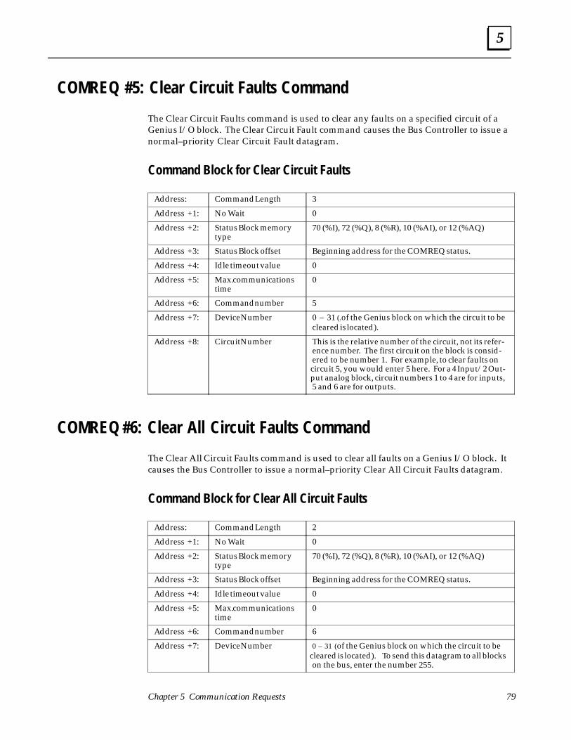
5
79Chapter 5 Communication Requests
COMREQ #5: Clear Circuit Faults Command
The Clear Circuit Faults command is used to clear any faults on a specified circuit of aGenius I/O block. The Clear Circuit Fault command causes the Bus Controller to issue anormal–priority Clear Circuit Fault datagram.
Command Block for Clear Circuit Faults
Address: Command Length 3
Address +1: No Wait 0
Address +2: Status Block memorytype
70 (%I), 72 (%Q), 8 (%R), 10 (%AI), or 12 (%AQ)
Address +3: Status Block offset Beginning address for the COMREQ status.
Address +4: Idle timeout value 0
Address +5: Max. communicationstime
0
Address +6: Command number 5
Address +7: Device Number 0 – 31 (.of the Genius block on which the circuit to becleared is located).
Address +8: Circuit Number This is the relative number of the circuit, not its refer-ence number. The first circuit on the block is consid-ered to be number 1. For example, to clear faults oncircuit 5, you would enter 5 here. For a 4 Input/2 Out-put analog block, circuit numbers 1 to 4 are for inputs,5 and 6 are for outputs.
COMREQ #6: Clear All Circuit Faults Command
The Clear All Circuit Faults command is used to clear all faults on a Genius I/O block. Itcauses the Bus Controller to issue a normal–priority Clear All Circuit Faults datagram.
Command Block for Clear All Circuit Faults
Address: Command Length 2
Address +1: No Wait 0
Address +2: Status Block memorytype
70 (%I), 72 (%Q), 8 (%R), 10 (%AI), or 12 (%AQ)
Address +3: Status Block offset Beginning address for the COMREQ status.
Address +4: Idle timeout value 0
Address +5: Max. communicationstime
0
Address +6: Command number 6
Address +7: Device Number 0 – 31 (of the Genius block on which the circuit to becleared is located). To send this datagram to all blockson the bus, enter the number 255.
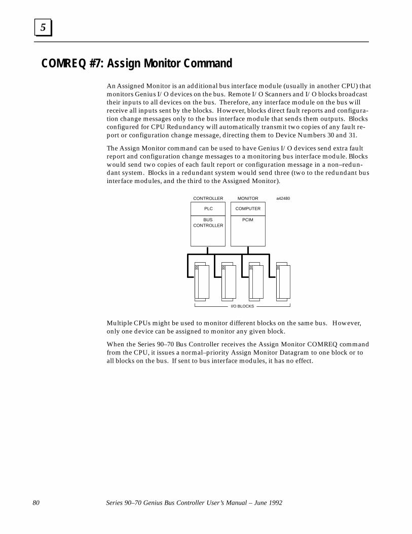
5
Series 90–70 Genius Bus Controller User’s Manual – June 199280
COMREQ #7: Assign Monitor Command
An Assigned Monitor is an additional bus interface module (usually in another CPU) thatmonitors Genius I/O devices on the bus. Remote I/O Scanners and I/O blocks broadcasttheir inputs to all devices on the bus. Therefore, any interface module on the bus willreceive all inputs sent by the blocks. However, blocks direct fault reports and configura-tion change messages only to the bus interface module that sends them outputs. Blocksconfigured for CPU Redundancy will automatically transmit two copies of any fault re-port or configuration change message, directing them to Device Numbers 30 and 31.
The Assign Monitor command can be used to have Genius I/O devices send extra faultreport and configuration change messages to a monitoring bus interface module. Blockswould send two copies of each fault report or configuration message in a non–redun-dant system. Blocks in a redundant system would send three (two to the redundant businterface modules, and the third to the Assigned Monitor).
MONITOR
BUSCONTROLLER
PCIM
PLCÎÎÎÎ
PLC
CONTROLLER a42480
I/O BLOCKS
ÎÎÎÎ
COMPUTER
Multiple CPUs might be used to monitor different blocks on the same bus. However,only one device can be assigned to monitor any given block.
When the Series 90–70 Bus Controller receives the Assign Monitor COMREQ commandfrom the CPU, it issues a normal–priority Assign Monitor Datagram to one block or toall blocks on the bus. If sent to bus interface modules, it has no effect.

5
81Chapter 5 Communication Requests
Command Block for the Assign Monitor Command
Address: Command Length 3
Address +1: No Wait 0
Address +2: Status Block memorytype
70 (%I), 72 (%Q), 8 (%R), 10 (%AI), or 12 (%AQ)
Address +3: Status Block offset Beginning address for the COMREQ status.
Address +4: Idle timeout value 0
Address +5: Max. communicationstime
0
Address +6: Command number 7
Address +7: Device Number of theblock(s) that shouldsend extra fault reports
0 – 31
Address +8: Device Number of thebus interface modulethat will RECEIVE theextra fault reports.
0 – 31 to send this command to one block. To sendthis command to ALL blocks, enter the number 255. Ifonly some blocks should report to the faults to theassigned monitor (for example, to minimize bus scan
time), program separate Assign Monitor commands toeach.
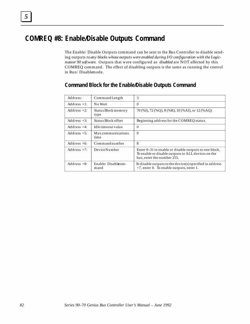
5
Series 90–70 Genius Bus Controller User’s Manual – June 199282
COMREQ #8: Enable/Disable Outputs Command
The Enable/Disable Outputs command can be sent to the Bus Controller to disable send-ing outputs to any blocks whose outputs were enabled during I/O configuration with the Logic-master 90 software. Outputs that were configured as disabled are NOT affected by thisCOMREQ command. The effect of disabling outputs is the same as running the controlin Run/Disable mode.
Command Block for the Enable/Disable Outputs Command
Address: Command Length 3
Address +1: No Wait 0
Address +2: Status Block memorytype
70 (%I), 72 (%Q), 8 (%R), 10 (%AI), or 12 (%AQ)
Address +3: Status Block offset Beginning address for the COMREQ status.
Address +4: Idle timeout value 0
Address +5: Max. communicationstime
0
Address +6: Command number 8
Address +7: Device Number Enter 0–31 to enable or disable outputs to one block.To enable or disable outputs to ALL devices on thebus, enter the number 255.
Address +8: Enable/Disable com-mand
To disable outputs to the device(s) specified in address+7, enter 0. To enable outputs, enter 1.

5
83Chapter 5 Communication Requests
COMREQ #9: Enable/Disable Global Data
If Global Data has been enabled using the Logicmaster 90 software, this COMREQ com-mand can be used after powerup to disable or re–enable the sending of Global Datafrom the Bus Controller, or receiving it from one or more devices on the bus.
If this COMREQ attempts to enable Global Data when it is already enabled, or to disableGlobal Data when it is already disabled, the Bus Controller ignores the request and re-turns status 4 (successful completion) to the Status Block.
Command Block for the Enable/Disable Global Data Command
Address: Command Length 3
Address +1: No Wait 0
Address +2: Status Block memorytype
70 (%I), 72 (%Q), 8 (%R), 10 (%AI), or 12 (%AQ)
Address +3: Status Block offset Beginning address for the COMREQ status.
Address +4: Idle timeout value 0
Address +5: Max. communicationstime
0
Address +6: Command number 9
Address +7: Device Number Enter 0–31 to specify the bus interface module to/from which Global Data is being enabled or disabled.This may be the Device Number of the Bus Control-ler itself, or of any other bus interface module on thebus.
To enable or disable the Bus Controller sending GlobalData, enter the Bus Controller ’s Device Number.
To enable or disable the Bus Controller receiving Glob-al Data from another bus interface module, enter theDevice Number of that bus interface module.
To enable or disable the Bus Controller sending orreceiving ANY Global Data, enter the number 255. If255 is entered, the command will complete success-fully if there are any controller devices on the bus.
Address +8: Enable/disable com-mand
To disable Global Data to or from the device specifiedin address +7, enter 0. To enable Global Data, enter 1.

5
Series 90–70 Genius Bus Controller User’s Manual – June 199284
COMREQ #10: Switch BSM Command
In a dual bus system, the Switch BSM command can be used to cause a Bus SwitchingModule to select a bus. This command causes the Bus Controller to issue a normal–priority Switch BSM datagram.
The program must already know which bus is currently selected. The CPU may issuethe Switch BSM command at intervals to ensure continued proper bus switching capa-bility. If the command is successful, the CPU will report a Loss of Block diagnostic for theBSM Controller block and for any other block on the same bus stub. If the dual bus sys-tem includes a second Bus Controller controlling the other bus, that Bus Controllershould report an Addition of Block diagnostic for each of those blocks. If the BSM posi-tion is currently forced by the Hand–held Monitor, the command will have no effect. Adata error is returned to the status reference if the block does not control a BSM.
Command Block for the Switch BSM Command
Address: Command Length 3
Address +1: No Wait 0
Address +2: Status Block memorytype
70 (%I), 72 (%Q), 8 (%R), 10 (%AI), or 12 (%AQ)
Address +3: Status Block offset Beginning address for the COMREQ status.
Address +4: Idle timeout value 0
Address +5: Max. communicationstime
0
Address +6: Command number 10
Address +7: Device Number of theGenius block to whichthe Bus SwitchingModule is attached
0–31
Address +8: Desired bus position Bus A (0) or Bus B (1). If not 0 or 1, syntax error is re-turned.

5
85Chapter 5 Communication Requests
COMREQ #11: Read Device Command
To read up to 128 bytes of data from another CPU and place it in PLC CPU memory, usethe Read Device command. This causes the Bus Controller to issue a normal–priorityRead Device datagram. When the data is received, it will automatically be placed in theCPU memory location specified in the Command Block.
Command Block for the Read Device Command
Address: Command Length 3
Address +1: No Wait 0
Address +2: Status Block memory type 70 (%I), 72 (%Q), 8 (%R), 10 (%AI), or 12 (%AQ)
Address +3: Status Block offset Beginning address for the COMREQ status.
Address +4: Idle timeout value 0
Address +5: Max. communications time 0
Address +6: Command number 11
Address +7: Device Number 0 – 31, for the device which is the source of thedata.
Address +8:Address +9:
Memory address, bytes 1, 2. ”
Specify the location where data will be readFROM. See the instructions on the followingpages. (It is not necessary to specify a memory
address when sending a Read Device COMREQto a computer).
Address +10:Address +11:Address +12:Address +13:
Program name, characters 1, 2” characters 3, 4
” characters 5, 6 ” characters 7, 8
Required to read %P or %L memory in anotherSeries 90–70 PLC. See the instructions on the
following pages. If the target of the command isNOT another Series 90–70 PLC, Address +10through Address +17 are ignored; they maycontain any value. Program names are limitedto 7 characters. Character 8 and all other trail-ing characters MUST be entered as nulls.
Address +14:Address +15:Address +16:Address +17:
Block name, characters 1, 2 ” characters 3, 4 ” characters 5, 6 ” characters 7, 8
Required to read %L memory in another Series90–70 PLC. For %P, Address +14 through Ad-dress +17 are ignored. Block names are limitedto 7 characters. Character 8 and all other trail-ing characters MUST be entered as nulls.
Address +18: Data length, in words, bytesor bits. This is the amount ofdata to be read.
Reading a Series 90–70 PLC, data length is bitsor words, depending on the memory type beingread. For other types of devices, the length is
given as expected by the device. The maximumlength is equal to 128 bytes.
Address +19: Maximum memory lengthneeded for the returned data
Value in bits or words (depends on memorytype selected below).
Address +20: Memory type to receive thereturned data
70 (%I), 72 (%Q), 8 (%R), 10 (%AI), or 12 (%AQ).
Address +21: Memory offset Starting address within this memory type.

5
Series 90–70 Genius Bus Controller User’s Manual – June 199286
Memor y Specification for Read Device and Write Device
The following pages explain how to specify the target memory type when sending aRead Device or Write Device datagram to a Series 90–70 PLC, Series Six PLC, Series FivePLC, or host computer.
Memor y Specification: Series 90–70 PLC
For a Series 90 PLC, in address + 8 enter the memory type, using one of the numberslisted in the table below.
TargetMemory
Type
Value(decimal) Description
Bits perRefer-ence
%L 0 Local register memory (each subroutine) 16
%P 4 Program register memory 16
%R 8 Register memory 16
%AI 10 Analog input memory 16
%AQ 12 Analog output memory 16
%I 1670
Discrete input memory (byte mode)Discrete input memory (bit mode)
81
%Q 1872
Discrete output memory (byte mode)Discrete output memory (bit mode)
81
%T 2074
Discrete temporary memory (byte mode)Discrete temporary memory (bit mode)
81
%M 22 76
Discrete momentary internal memory (byte mode)Discrete momentary internal memory (bit mode)
81
%SA 2478
Discrete system memory group A (byte mode)Discrete system memory group A (bit mode)
81
%SB 2680
Discrete system memory group B (byte mode)Discrete system memory group B (bit mode)
81
%SC 2882
Discrete system memory group C (byte mode)Discrete system memory group C (bit mode)
81
%S 3084
Discrete system memory (byte mode)Discrete system memory (bit mode)
81
%G 5686
Discrete Genius automatic global data table (byte mode)Discrete Genius automatic global data table (bit mode)
81
Memor y Offset for Series 90–70 PLC
In address +9, enter a numerical offset within this memory type, for the beginning ofthe data. Memory offsets start at 0; thus %R1 and %I1 are both accessed using aMemory Offset of 0.
For 3 bits starting at %I0014, you would enter the offset 13, and a data length of 3 bits.
To write data to a Series 90–70 PLC beginning at %R100, you would enter the MemoryType 8 (decimal) and the Memory Offset 99 (decimal).
Example A:
Example B:
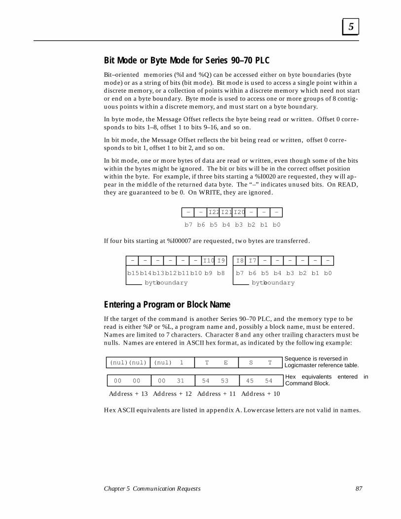
5
87Chapter 5 Communication Requests
Bit Mode or Byte Mode for Series 90–70 PLCBit–oriented memories (%I and %Q) can be accessed either on byte boundaries (bytemode) or as a string of bits (bit mode). Bit mode is used to access a single point within adiscrete memory, or a collection of points within a discrete memory which need not startor end on a byte boundary. Byte mode is used to access one or more groups of 8 contig-uous points within a discrete memory, and must start on a byte boundary.
In byte mode, the Message Offset reflects the byte being read or written. Offset 0 corre-sponds to bits 1–8, offset 1 to bits 9–16, and so on.
In bit mode, the Message Offset reflects the bit being read or written, offset 0 corre-sponds to bit 1, offset 1 to bit 2, and so on.
In bit mode, one or more bytes of data are read or written, even though some of the bitswithin the bytes might be ignored. The bit or bits will be in the correct offset positionwithin the byte. For example, if three bits starting a %I0020 are requested, they will ap-pear in the middle of the returned data byte. The “–” indicates unused bits. On READ,they are guaranteed to be 0. On WRITE, they are ignored.
–
b7
–
b6
I22
b5
I21
b4
I20
b3
–
b2
–
b1
–
b0
If four bits starting at %I00007 are requested, two bytes are transferred.
–
b15
–
b14
–
b13
–
b12
–
b11
–
b10
I10
b9
I9
b8
I8
b7
I7
b6
–
b5
–
b4
–
b3
–
b2
–
b1
–
b0
byte boundarybyte boundary
Entering a Program or Block NameIf the target of the command is another Series 90–70 PLC, and the memory type to beread is either %P or %L, a program name and, possibly a block name, must be entered.Names are limited to 7 characters. Character 8 and any other trailing characters must benulls. Names are entered in ASCII hex format, as indicated by the following example:
(nul)(nul) (nul) 1 T E S T
00 00 00 31 54 53 45 54
Sequence is reversed in Logicmaster reference table.
Hex equivalents entered inCommand Block.
Address + 13 Address + 12 Address + 11 Address + 10
Hex ASCII equivalents are listed in appendix A. Lowercase letters are not valid in names.
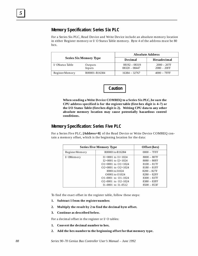
5
Series 90–70 Genius Bus Controller User’s Manual – June 199288
Memor y Specification: Series Six PLCFor a Series Six PLC, Read Device and Write Device include an absolute memory locationin either Register memory or I/O Status Table memory. Byte 4 of the address must be 80hex.
Series Six Memory TypeAbsolute Address
Series Six Memory Type Decimal Hexadecimal
I/O Status Table OutputsInputs
08192 – 0831908320 – 08447
2000 – 207F2080 – 20FF
Register Memory R00001–R16384 16384 – 32767 4000 – 7FFF
Caution
When sending a Write Device COMREQ to a Series Six PLC, be sure theCPU address specified is for the register table (first hex digit is 4–7) orthe I/O Status Table (first hex digit is 2). Writing CPU data to any otherabsolute memory location may cause potentially hazardous controlconditions.
Memor y Specification: Series Five PLCFor a Series Five PLC, [Address+8] of the Read Device or Write Device COMREQ con-tain a memory offset, which is the beginning location for the data:
Series Five Memory Type Offset (hex)
Register Memory R00001 to R16384 0000 – 7FFF
I/O Memory I1+0001 to I1+1024I2+0001 to I2+1024
O1+0001 to O1+1024O2+0001 to O2+1024
I0001 to I1024O0001 to O1024
O1–0001 to O1–1024O2–0001 to O2–1024
I1–0001 to I1–0512
8000 – 807F8080 – 80FF8100 – 817F8180 – 81FF8200 – 827F 8280 – 82FF8300 – 837F8380 – 83FF8500 – 853F
To find the exact offset in the register table, follow these steps:
1. Subtract 1 from the register number.
2. Multiply the result by 2 to find the decimal byte offset.
3. Continue as described below.
For a decimal offset in the register or I/O tables:
1. Convert the decimal number to hex.
2. Add the hex number to the beginning offset for that memory type.

5
89Chapter 5 Communication Requests
Example of Read DeviceIn the following example, a Series 90–70 PLC reads ten words of %P memory starting atlocation %P0050 from program “TEST1” in another Series 90–70 PLC.
COMMREQ
IN FT
SYSID
TASK
%Q00001
%R0001–
CONST–
CONST–
––| |––
00002
00001
––––––( )––
%Q00002––––––( )––
GeniusBus ��
Series 90–70 PLC Series 90–70 PLC
GBC #31 GBC #29
Program Name
Initiating Device
Target DeviceCommand Block Location
Status Block Location
Memory location to read data from
Memory location to place data
COMREQ Output References
(COMREQ Status)
(COMREQ parameters)
ABC
X
%R001–%R022
%R023–%R024
%Q001, %Q002
%AQ050–%AQ060
%P050–%P060
X
TEST1
When the data is received from the target PLC, the requesting PLC will store it begin-ning at %AQ0050 in its own memory.
Example Command Block
Command BlockRegister Description Value Comment
Address +1Address +2Address +3Address +4Address +5Address +6Address +7Address +8Address +9Address +10Address +11Address +12Address +13Address +14Address +15Address +16Address +17Address +18Address +19Address +20Address +21
Wait/No WaitMemory type for Status Pointer
Starting address for Status PointerTimeout valueMax Communication TimeCommand CodeDevice NumberMemory Address bytes 1 & 2Memory Address bytes 3 & 4Program Name characters 1 & 2Program Name characters 3 & 4Program Name characters 5 & 6Program Name character 7 & 8Block Name characters 1 & 2Block Name characters 3 & 4Block Name characters 5 & 6Block Name character 7 & 8Data length (word) to readDestination length (words)Memory type for received dataMemory offset for data
0822001129249
’ET’’TS’ ’1’xx
10101249
No Wait%R memory %R023 (1 + 22 offset)Not used for No WaitNot used for No WaitRead DeviceTarget Bus Controller %P memory%P0050 (1 + 49 offset)TEST1
character 6 is null *Ignored (don’t care)Ignored IgnoredIgnored Ignored10 words 10 words%AQ memory %AQ0050 (1+49 offset)
* In hex, the two values in Address +12 are 31h (ASCII 1) and 00h (ASCII nul).

5
Series 90–70 Genius Bus Controller User’s Manual – June 199290
COMREQ #12: Write Device CommandTo send up to 128 bytes of data to another CPU on the bus, use the Write Device com-mand. Any type of data that can be addressed by its memory type and offset can besent. This command causes the Bus Controller to issue a normal–priority Write Devicedatagram to the specified device. To send a Write Device datagram with high priority,see COMREQ #14: Send Datagram.
Using Write Device Messages Instead of Global DataWrite Device datagrams can be used together with Global Data, or can replace GlobalData. Consider using Write Device datagrams instead of Global Data if Global Datatakes up too much bus scan time for the application, data does not need to be sent everybus scan, or the CPU sweep time becomes too long for the application.
If this datagram will be broadcast, and there is another Series 90–70 Bus Controller onthe bus that should NOT receive it, send the datagram using COMREQ #14 instead.See page 94.
Command Block for the Write Device CommandAddress: Command Length 13 – 77. Enter the number of words from Ad-
dress +6 to the end of the data.
Address +1: No Wait 0Address +2: Status Block memory type 70 (%I), 72 (%Q), 8 (%R), 10 (%AI), or 12
(%AQ)Address +3: Status Block offset Beginning address for the COMREQ status.Address +4: Idle timeout value 0
Address +5: Max. communications time 0
Address +6: Command number 12
Address +7: Device Number 0 – 31, for the device to be written to.
Address +8:Address +9:
Memory address, bytes 1, 2. ”
Enter the location for data to be written to.See the instructions for “Read Device”. (It isnot necessary to specify a memory addresswhen sending a Write Device COMREQ to acomputer).
Address +10:Address +11:Address +12:Address +13:
Program name, characters 1, 2.” characters 3, 4.
” characters 5, 6. ” characters 7, 8.
Required to write %P or %L memory inanother Series 90–70 PLC. See the instruc-tions for “Read Device”. If the target of thecommand is NOT another Series 90–70 PLC,Address +10 through Address +17 are ig-nored; they may contain any value.
Address +14:Address +15:Address +16:Address +17:
Block name, characters 1, 2. ” characters 3, 4. ” characters 5, 6. ” characters 7, 8.
Required to write %L memory in another Se-ries 90–70 PLC. For %P, Address +14 throughAddress +17 are ignored. Block names arelimited to 7 characters. Character 8 and allother trailing characters MUST be entered asnulls.
Address +18: Data length, in words, bytesor bits. This is the amount ofdata to be read.
Writing a Series 90–70 PLC, data length is bitsor words, depending on the memory type be-ing read. For other types of devices, the
length is given as expected by the device. Themaximum length is equal to 128 bytes.
Address +19 toAddress +n:
Data to be written to the otherdevice.
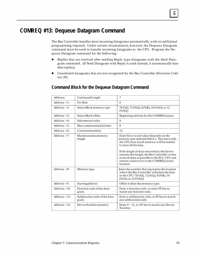
5
91Chapter 5 Communication Requests
COMREQ #13: Dequeue Datagram Command
The Bus Controller handles most incoming datagrams automatically, with no additionalprogramming required. Under certain circumstances, however, the Dequeue Datagramcommand must be used to transfer incoming datagrams to the CPU. Program the De-queue Datagram command for the following:
� Replies that are received after sending Reply–type datagrams with the Send Data-gram command. (If Send Datagram with Reply is used instead, it automatically han-dles replies).
� Unsolicited datagrams that are not recognized by the Bus Controller (Function Codenot 20).
Command Block for the Dequeue Datagram Command
Address: Command Length 7
Address +1: No Wait 0
Address +2: Status Block memory type 70 (%I), 72 (%Q), 8 (%R), 10 (%AI), or 12(%AQ)
Address +3: Status Block offset Beginning address for the COMREQ status.
Address +4: Idle timeout value 0
Address +5: Max. communications time 0
Address +6: Command number 13
Address +7: Maximum data memorylength
Enter bit or word value (depends on thememory type selected below). This entry tellsthe CPU how much memory will be neededto store all the data.
If the length of data returned by the deviceexceeds this length, the Bus Controller writesas much data as possible to the PLC CPU andreturns a data error to the COMREQ statuslocation.
Address +8: Memory type Enter the number that represents the locationwhere the Bus Controller will place the datain the CPU: 70 (%I), 72 (%Q), 8 (%R), 10(%AI), or 12 (%AQ)
Address +9 Starting address Offset within this memory type.
Address +10 Function code of the data-gram.
Enter a function code. or enter FF hex tomatch any function code.
Address +11: Subfunction code of the data-gram.
Enter a subfunction code, or FF hex to matchany subfunction code.
Address +12: Device Number (sender) Enter 0 – 31, or FF hex to match any DeviceNumber.

5
Series 90–70 Genius Bus Controller User’s Manual – June 199292
Number of Dequeue Datagram Commands Needed
One Dequeue Datagram command is needed for each incoming datagram. If multipleincoming Datagrams are expected during one CPU sweep, it will be necessary to placemultiple Dequeue Datagram commands in the program to assure their efficient transferto the CPU.
The number of Dequeue Datagram commands needed depends on whether the Data-grams have been sent using Normal or High Priority, and the relative lengths of the CPUsweep time and the scan time of the bus, as explained below.
If the Bus Scan Time is Greater than the CPU Sweep Time
If all Datagrams on the bus are sent with Normal Priority, there is a limit of one incomingDatagram per CPU sweep. Therefore, only one Dequeue Datagram command persweep will be needed to handle incoming Datagrams.
If all Datagrams on the bus are sent with High Priority, the Bus Controller can potentiallyreceive one Datagram from each transmitting device during a scan. The program shouldinclude the same number of Dequeue Datagram commands as incoming Datagrams.
If the Bus Scan Time is Less than the CPU Sweep Time
If the bus scan time is significantly shorter than the CPU sweep time, you can estimatethe number of Dequeue Datagram commands that must be sent to the Bus Controller toaccommodate incoming Datagrams on that bus.
First, determine how many scans can occur in one CPU sweep. For example, if the busscan were 20mS and the CPU sweep were 90mS, the ratio between them would be 4.5 to1. This should be rounded upward to 5.
This is the maximum number of Normal Priority Datagrams that might be received in asingle CPU sweep. Plan to have the same number of Dequeue Datagram commands tothat Bus Controller in the program to handle the incoming Datagrams.
For High Priority Datagrams, multiply the number found above by the total number ofdevices on the bus that might send a High Priority Datagram to the Bus Controller inone bus scan. This is the total number of incoming Datagrams from that bus the pro-gram might have to handle in a single CPU sweep. Plan on this number of Dequeue Da-tagram commands to the Bus Controller.
Additional Logic for Incoming Datagrams
Up to 16 datagrams are enqueued by the Bus Controller in an internal queue. These in-clude any unsolicited reply–type datagrams. This permits the program to, for example,send a Read ID Send Datagram and dequeue the Read ID Reply with the Dequeue Data-gram COMREQ.
If the 16–item queue fills, an informational fault GBC_SOFTWR_EXCPTN is logged(Fault Type is DQ_QUEUE_FULL) in the I/O Fault Table. If the Dequeue Datagram isissued and there are no datagrams in the queue, the Status Pointer is set to NO DATATO TRANSFER.

5
93Chapter 5 Communication Requests
Program logic should be used to assure that no datagrams are lost by being accidentallywritten over. This might be done by copying each datagram to another memory loca-tion, or by changing the data memory location specified in the Command Block aftereach incoming datagram is received.
Format of Returned Data
The Dequeue Datagram returns data in the following format.
Location High Byte Low Byte
Memory Address Data Length Status byte
Memory address +1 Subfunction code Function code
Memory address +2 Data byte 2 Data byte 1
�
�
�
�
�
�
�
�
�
Memory address +69 Data byte 134 Data byte 133
Items are explained below.
The status byte reports the Device Number of the device that sent thedatagram. It also indicates whether the message was broadcast or di-rected by the other device.
B/D x x n n n n n
bit 7 6 5 4 3 2 1 0
Device Number
Unused
Broadcast (1)Directed (0)
(5 bits: 0–31 decimal)
The number (0 to 134) of data bytes after the subfunction code.
The function code of the received message: 0 to 111 decimal or 0 to 6Fhex.
The subfunction code of the received message: 0 to 255 decimal or 0 toFF hex.
Status Byte:
Data Length:
FunctionCode:
SubfunctionCode:

5
Series 90–70 Genius Bus Controller User’s Manual – June 199294
COMREQ #14: Send Datagram CommandMost datagrams are normally programmed using their assigned COMREQ commandnumbers. However, datagrams can also be sent using the Send Datagram command andthe Request Datagram Reply command. The Send Datagram command might be usedto send:
� Datagrams for which no COMREQ command number is defined, such as BeginPacket Sequence, End Packet Sequence, and Write Point.
� Read Device and Write Device datagrams that are broadcast, but which should beignored by another Series 90–70 Bus Controller.
� Datagrams that must be guaranteed transmission during the next bus scan. Thisshould be done with restraint, for the reasons explained on the following pages.
� Datagrams which do not cause another device to send back a reply, such as PulseTest, or Write Configuration.
Datagrams which DO cause another device to send back a reply, such as Read Diag-nostics or Read Configuration, are usually programmed using their assigned COM-REQ numbers or the Request Datagram Reply command (COMREQ #15). Howev-er, if Send Datagram is used to send datagrams that cause replies, the DequeueDatagram command must be used to transfer the replies back to the CPU.
Before using Send Datagram, refer to the table on page 74 for more information aboutCOMREQs and datagrams.
Command Block for the Send Datagram Command
Address: Command Length 6 – 70. Enter the number of words from Ad-dress +6 to Address +n.
Address +1: No Wait 0Address +2: Status Block memory type 70 (%I), 72 (%Q), 8 (%R), 10 (%AI), or 12 (%AQ)Address +3: Status Block offset Beginning address for the COMREQ status.Address +4: Idle timeout value 0
Address +5: Max. communications time 0
Address +6: Command number 14
Address +7: Device Number of the de-vice to receive the mes-sage.
0 – 31, or 255 to broadcast the message.
Address +8: Function code For any datagram listed below, 32 decimal (20 hex).
Address +9 Subfunction code (hex) See the list on page 74.
Address +10 Priority Enter 0 for normal priority, or 1 for high priority.
Address +11: Datagram length (in bytes) Enter the actual length of the Datagram, beginningat [address +12].
Address +12:to Address+n:
Datagram content Enter the entire datagram as part of the CommandBlock. The Genius I/O System User’s Manual showsdatagram structures.
If the Send Datagram command is used to broadcast aWrite Device datagram, and that datagram should beIGNORED by another Series 90–70 Bus Controller, setthe first byte of the datagram as shown in the SystemUser’s Manual (this byte is normally 0), to FE hex.

5
95Chapter 5 Communication Requests
Datagram Priority A Bus Controller can send one datagram per bus scan. That datagram may be assignedeither normal priority or high priority. Therefore, during one bus scan, there may be onenormal priority datagram followed by up to 31 high priority datagrams, or up to 32 highpriority datagrams sent by the devices on the bus.
In one bus scan (one complete rotation of the bus token among all devices on the bus),there can be just one normal priority datagram sent by any device. If a normal prioritydatagram or similar system message (such as a fault report) has already been sent by anydevice (including itself), a device must wait until its next turn on the bus before it cansend a normal priority datagram.
Datagrams and I/O BlocksIf the bus will also be used for I/O block control, normal priority datagrams are recom-mended to allow other messages such as fault reports (which the system handles as nor-mal priority datagrams) to get through. In addition, normal priority datagrams ensurethat bus scan time is only modestly delayed for communications. Bus scan time affectsthe response time of any I/O data on the bus. If there are I/O blocks on the bus, use highpriority only if the datagram transmission cannot be delayed. Normal priority will worksatisfactorily except when there are many devices attempting to send datagrams simul-taneously.
Number of Datagrams per CPU SweepThe application program should include logic that verifies successful completion of earli-er datagrams before requesting new ones. Because a Bus Controller can only send onedatagram per bus scan, the number of datagrams that can be executed during the sameCPU sweep of program logic depends on the relative lengths of the CPU sweep and thebus scan.
If the Bus Scan Time is Greater than the CPU Sweep Time: If the bus scan time isgreater than the CPU sweep time, the Bus Controller will be able to send no more thanone datagram during one execution of the application program. Successful transmissionof a normal priority datagram will depend on the absence of datagram and system mes-sage traffic on the bus.
If the Bus Scan Time is Less than the CPU Sweep Time: If the bus scan time is signifi-cantly shorter than the CPU sweep time, the bus may be able to transmit multiple data-grams during one execution of the application program.
Effect of Datagrams on the Genius I/O Bus: Normal Priority Datagrams allow fault re-ports and Hand–held Monitor communications on a bus to continue undisturbed. Onlyone Normal Priority Datagram is allowed each bus scan, so the scan time stays relativelyconstant, and I/O update timing varies only by small increments.
If High Priority Datagrams are being transmitted constantly, the Hand–held Monitorwill not function properly; fault reports from blocks will be prevented from being trans-mitted on the bus, and regular Communication Request commands (such as Write Con-figuration commands) to that Bus Controller will fail with a transmission error. For thesereasons, use of High Priority Datagrams on a bus with I/O blocks should be avoided ifpossible.
If High Priority Datagrams are transmitted infrequently, they will cause some delay inthe Hand–held Monitor communications and other normal system messages, but thedelay should not be noticeable.

5
Series 90–70 Genius Bus Controller User’s Manual – June 199296
High Priority Datagrams will typically put more pressure on the Bus Controller to trans-fer multiple Datagrams per CPU sweep. However, this can also occur with NormalPriority Datagrams if the bus scan time is much shorter than the CPU sweep time.
Maximum CPU Sweep Time Increase for Datagrams: To estimate the impact of Data-grams on CPU sweep time, add together the times required for all Datagrams that mightbe sent between the Bus Controller and the CPU during one sweep if No Wait mode isselected. Repeat this for each Bus Controller in the PLC that sends or receives Data-grams.
Total Datagram Bytes Sent x .031mS =(may be none)
+ LARGEST incoming Normal PriorityDatagram Received, bytes x .031mS =
OR
+ Total incoming High PriorityDatagrams Bytes Received x .031mS =
+ 1.200mS = ______mS
Additional Information about TimingIf you need more information about timing for datagrams, Global Data, I/O devices, andremote drops, please refer to the Genius I/O System User’s Manual.
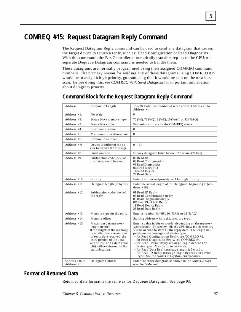
5
97Chapter 5 Communication Requests
COMREQ #15: Request Datagram Reply Command The Request Datagram Reply command can be used to send any datagram that causesthe target device to return a reply, such as: Read Configuration or Read Diagnostics.With this command, the Bus Controller automatically transfers replies to the CPU; noseparate Dequeue Datagram command is needed to handle them.
These datagrams are normally programmed using their assigned COMREQ commandnumbers. The primary reason for sending any of these datagrams using COMREQ #15would be to assign it high priority, guaranteeing that it would be sent on the next busscan. Before doing this, see COMREQ #14: Send Datagram for important informationabout datagram priority.
Command Block for the Request Datagram Reply Command
Address: Command Length 10 – 78. Enter the number of words from Address +6 toAddress +n.
Address +1: No Wait 0
Address +2: Status Block memory type 70 (%I), 72 (%Q), 8 (%R), 10 (%AI), or 12 (%AQ)
Address +3: Status Block offset Beginning address for the COMREQ status.
Address +4: Idle timeout value 0
Address +5: Max. communications time 0
Address +6: Command number 15
Address +7: Device Number of the de-vice to receive the message.
0 – 31
Address +8: Function code For any datagram listed below, 32 decimal (20 hex).
Address +9 Subfunction code (hex) ofthe datagram to be sent.
00 Read ID02 Read Configuration 08 Read Diagnostics0C Read Block I/O1E Read Device27 Read Data
Address +10 Priority Enter 0 for normal priority, or 1 for high priority.
Address +11: Datagram length (in bytes) Enter the actual length of the Datagram, beginning at [ad-dress +16].
Address +12: Subfunction code (hex) ofthe reply
01 Read ID Reply03 Read Configuration Reply09 Read Diagnostics Reply0D Read Block I/O Reply1F Read Device Reply28 Read Data Reply
Address +13: Memory type for the reply Enter a number: 8 (%R), 10 (%AI), or 12 (%AQ)
Address +14: Memory offset Starting address within this memory type.
Address +15: Maximum data memorylength neededIf the length of the memoryis smaller than the amountof reply data received, theextra portion of the data
will be lost, and a data error(16) will be returned to thestatus location.
Enter a value in bits or words, depending on the memorytype selected. This entry tells the CPU how much memorywill be needed to store all the reply data. The length de-pends on the message and device type. – for Read Configuration Reply, see COMREQ #2. – for Read Diagnostics Reply, see COMREQ #4. – for Read Device Reply, message length depends on device type. May be up to 64 words. – for Read Data Reply, message length is 5 words. – for Read ID Reply, message length depends on device type. See the Genius I/O System User’s Manual.
Address +16 toAddress +n:
Datagram Content Enter the entire datagram as shown in the Genius I/O Sys-tem User’s Manual.
Format of Returned DataReturned data format is the same as for Dequeue Datagram. See page 93.

5
Series 90–70 Genius Bus Controller User’s Manual – June 199298
COMREQ #16: Enable/Disable I/O Fault Categories
The Enable/Disable I/O Fault Categories command can be sent to the Bus Controller todisable or re–enable the reporting of all I/O faults, or Addition/Loss of Block faults.
If all I/O faults are disabled, the Bus Controller will not forward to the CPU any fault re-ports it receives from devices on its bus. This includes all I/O faults, as well as Loss ofBlock and Addition of Block messages.
It is also possible to disable only reports of Addition or Loss of Block conditions, whilestill forwarding other faults from the devices on the bus. This can be useful in a systemwhere blocks are intentionally switched on and off the bus, or in other applicationswhere these messages are not wanted.
If the passing of some or all fault reports is disable, the corresponding point–specificfault contacts will operate. They are not affected by the use of this COMREQ. Some sys-tem–level and block–level fault contacts will be affected by the loss of the inhibited in-formation.
Command Block for the Enable/Disable I/O Fault Categories Command
Address: Command Length 3
Address +1: No Wait 0
Address +2: Status Block memorytype
70 (%I), 72 (%Q), 8 (%R), 10 (%AI), or 12 (%AQ)
Address +3: Status Block offset Beginning address for the COMREQ status.
Address +4: Idle timeout value 0
Address +5: Max. communicationstime
0
Address +6: Command number 16
Address +7: I/O Fault Category tobe enabled or disabled.
It may be: 0 0 0 0 all I/O fault categories enabled. F F F F all I/O fault categories disabled. 0 0 0 6 Addition/Loss of Block fault
categories disabled.
Address +8: Must be: 0 0 0 0 if Address +7 is 0000 or 0006.Must be: F F F F if Address +7 is FFFF.
The default is for all fault categories to be enabled.

6 section level 1 1figure bi level 1 table_big level 1
99
Chapter 6 Data Monitoring, Distributed Control,and Redundancy
This chapter describes the following types of advanced I/O control systems:
� Data Monitoring: Where an additional CPU (either a PLC or a computer) monitorsinputs and diagnostics from some or all of the blocks on a bus.
� Distributed control: Where two or more CPUs control different I/O blocks on thesame bus.
� Redundancy: The use of dual busses, dual controllers, or both.
These types of systems are possible because of the unique operation and communica-tions capabilities of Genius I/O devices on a bus. Each Genius I/O block broadcasts itsinput messages to all other devices on the bus. Therefore, more than one CPU can re-ceive inputs from the same blocks.
The CPUs can communicate on the same bus, allowing formation of a common data-base. In addition, any CPU can send datagram messages to any other device on the bus.
For Additional Information, Also See:
Chapter 1, which describes non–redundant types of systems.
Chapter 4 for configuration details.
Chapter 5 for descriptions of COMREQs that might be used in a monitoring or redun-dancy system.

6
Series 90–70 Genius Bus Controller User’s Manual – June 1992100
Data Monitoring
In addition to the PLC or computer running the application program, other CPUs on thebus can monitor inputs, diagnostics, and Configuration Change messages sent by GeniusI/O devices.
MONITOR
BUSCONTROLLER
BUSCONTROLLER
CPU
CONTROLLER a43460
PHASE B I/O BLOCKS
CPU
Monitoring Inputs Genius I/O devices broadcast their inputs once per bus scan. These inputs may be ac-cessed by any PLC or computer on the bus.
If the Series 90–70 PLC is to be used to monitor inputs from I/O devices not being con-trolled by its application program, the devices will be configured in the same manner asother I/O devices on the bus. The PLC will use the Reference Number assigned to eachI/O device to store its inputs. Even though the monitoring PLC would not ordinarily beexpected to send outputs to devices being monitored, outputs to those devices should bedisabled when the PLC’s I/O configuration is done. This will prevent any unwantedoutputs being sent to the I/O devices from the monitoring PLC.
If a computer is used to monitor I/O data on the bus, it is important to consider datatype, message length, and message format when programming the computer. For exam-ple, a High–speed Counter block sends its word–type data first, followed by discretedata. Other devices have different data formats.
Monitoring Diagnostics and Configuration Change MessagesIn addition to receiving the broadcast input data, one PLC or computer on the bus mayalso receive extra copies of any fault reports and configuration change messages thatmay be sent by the bus devices. This PLC or computer, referred to as the Assigned Mon-itor, may not send control outputs to an I/O device. If the monitor is capable of sendingoutputs to a I/O device it is monitoring, those outputs must be disabled.
The monitoring device can communicate with other devices on the bus through GlobalData or datagram messages. For example, it would be possible for a monitoring deviceto send a Read Diagnostics datagram to an I/O device that was not configured to send itfault reports automatically.
This feature is compatible with both redundant and non–redundant Genius configura-tions.

6
101Chapter 6 Data Monitoring, Distributed Control, and Redundancy
Distributed Control
Distributed control means that two or more Bus Controllers are sending control outputsto different I/O devices on the same bus. Ordinarily, these Bus Controllers would be indifferent PLCs, but with the Series 90–70, they may also be in the same PLC.
Diagnostics are only automatically sent from the block to the Bus Controller that is con-trolling its outputs. The Assign Monitor datagram can be used to command blocks onthe bus to also direct fault reports to a second Bus Controller.
This is a form of split control, not a type of redundancy. Bus Controllers and devices onthe bus are set up for CPU Redundancy Mode = None, since each I/O device is receivingoutputs from only one Bus Controller. Remember that all I/O devices on the bus broad-cast inputs to all bus interface modules automatically.
For example, a Bus Controller is configured at Bus Address 31, and the I/O devices it willcontrol are configured at Bus Addresses 1 and 2. A Bus Controller in another PLC is lo-cated at Bus Address 30. The I/O blocks it will control are located ate Bus Addresses 3and 4. A third Bus Controller is at Bus Address 7. Two I/O blocks on its bus are located atBus Addresses 5 and 6. All devices are connected by the same bus.
ÎÎÎÎÎÎ
ÎÎÎÎÎÎ
a43458
CPU
BUSCONTROLLER
(DEVICE 31)OUTPUTS
1 2 3 4
ÎÎÎÎÎÎ Î
ÎÎ
BUSCONTROLLER
(DEVICE 30)
CPU
5 6
ÎÎÎÎ
BUSCONTROLLER
(DEVICE 7)
CPU
ÎÎÎÎÎÎ
When setting up a Series 90–70 PLC system for distributed control, there are two differ-ent ways to assign references to I/O devices:
A. Each Bus Controller can be assigned just those I/O devices whose outputs it controls.If this is done, devices that are not configured for a Bus Controller (but which areactually present on the bus) will generate Extra Device faults in that PLC at startup.Once these faults are cleared, they will not reappear unless power is cycled to theBus Controller or I/O device.
B. Each Bus Controller can be assigned all of the I/O devices actually present on thebus. Outputs are disabled to I/O devices controlled by another Bus Controller. Thismeans that each I/O device must be assigned a Reference Number in each CPU.References assigned to devices controlled by another CPU are unavailable for fur-ther use.
6
Series 90–70 Genius Bus Controller User’s Manual – June 1992102
Redundancy
Redundancy provides extra protection for critical processes through duplication of sys-tem components. For the Series 90–70 PLC (CPU rev. 4.0 and Bus Controller rev. 4.0),the following can be configured using Logicmaster 90–70 rev. 4.0:
� Dual bus, one PLC
� Dual bus, two PLCs
� Redundant controllers, one PLC
� Redundant controllers, two PLCs
� Dual bus and redundant controllers, two PLCs
Systems that are appropriate for a rev. 4 Series 90–70 PLC are described on the follow-ing pages. If the Series 90–70 PLC is rev. 3, see page 115.
Important ConsiderationsSuitability of Series 90–70 PLC redundancy depends on the requirements of the ap-plication. Some important factors to be considered are described below.
1. CPU synchronization is not supported.
1. Using a Genius LAN, transfer of data from the master CPU data to the back-up CPU can take 10 to 20 CPU sweeps, depending on the quantity of data.
2. The Series 90–70 PLC has transitional bits, but does not have a table thatcan be transferred from one CPU to another for synchronization. One–shots, counters, and transitional contacts cannot be guaranteed to be thesame in both PLCs.
3. The timebase is not transferrable, so timers (real time and running time)cannot be guaranteed to be the same. In addition, timers and counters usedin program blocks which are not called every sweep may produce differentresults.
4. For PID function blocks, elapsed time may be different in the two PLCs, be-cause it represents the total time since PLC powerup.
2. Hot Standby redundancy should only be used for systems that do not requirebumpless transfer of control from one CPU to the other.
3. A higher level of support for both bus redundancy and CPU redundancy is pro-vided by Release 4 products (Series 90–70 PLC rel. 4, Logicmaster 90–70 rel. 4,and Series 90–70 Genius Bus Controller, version 4.0). These versions shouldtherefore be used for redundant systems. The restrictions listed above still apply,however.

6
103Chapter 6 Data Monitoring, Distributed Control, and Redundancy
Dual Bus Redundancy
Dual busses can be used to provide backup protection against cable break or loss or re-moval of a Bus Controller. Each bus of the dual bus pair has its own Bus Controller. Thetwo Bus Controllers can be located in the same PLC or in two PLCs.
If the Bus Controllers are in the same PLC, they can be placed in the same rack, or theycan be placed in different racks to protect against rack failure.
For applications that do not require bumpless transfer of control, the Bus Controllers canbe located in different PLCs.
Note
If bumpless transfer is a requirement, bus redundancy with two PLCs isnot recommended since the second PLC is essentially off–line before theswitch.
Dual Bus OperationIn dual bus redundancy, bus selection is controlled by a switching device (either a BusSwitching Module, or a Remote I/O Scanner module with built–in bus switching capa-bility).
ÏÏÏÏÏÏ
a42360BUSCONTROLLER
BUSCONTROLLER
BUS A
BUS B
UP TO 7 MORE BLOCKS
BSM
BSMCONTROLLER
BLOCK
ÏÏÏÏÏÏ
ÏÏÏÏÏÏ
Clusters of up to eight devices each can be connected to a dual bus by a switching de-vice. The maximum number of devices that can be located on both busses is 30, whichrequires at least 4 bus switching devices.
If the bus switching device stops receiving outputs from the active bus, it automaticallyswitches to the other bus. If the bus it switches to is operational, the regular I/O updateswill resume with the Bus Controller on the new bus. An “Output Default Timeout” of2.5 or 10 seconds must be selected for each bus device, so its outputs do not default dur-ing this switchover/login process. Bus switching and block login requires finite periodsof time. This varies from system to system, depending on the Genius bus scan time, theCPU sweep time, and the number of devices switching. Generally, switchovers are com-pleted before the 2.5 second timeout expires. The 10–second option is available for sys-tems requiring a longer switchover period. During the timeout period, outputs holdtheir last valid output state.
If, after switching due to loss of communications on the original bus, no outputs are re-ceived on the new bus, the bus switching device does not switch back. It waits until

6
Series 90–70 Genius Bus Controller User’s Manual – June 1992104
communications are restored on the newly–connected bus, or until power is cycled.This prevents unnecessary switching when no communications are available.
Data Transfer on a Dual Bus
In dual bus redundancy, both Bus Controllers are capable of sending outputs to the de-vices on the bus. However, the devices in a bus cluster will only receive outputs fromthe bus that is currently selected by their switching device.
Similarly, although the devices in a cluster continually broadcast input data and diagnos-tic messages, they are only received by the Bus Controller on the bus that is currentlyselected by their switching device. The Bus Controller on the inactive bus cannot receiveinputs, fault reports or Configuration Change messages.
Non–redundant Devices on a Dual Bus
Although most devices in a dual bus system will probably be connected to both buscables via a switching device, it is possible to have non–redundant devices connecteddirectly to one bus of the pair. The following illustration represents a dual bus with somenon–redundant I/O blocks.
BUSCONTROLLER
A(DEVICE 31)
BUS A
BUS B
BUSCONTROLLER
B(DEVICE 31)
ÏÏÏÏÏÏÏÏÏÏÏÏ
BSM
1 2
a42475
3 4A
4B
ÏÏÏÏÏÏÏÏÏ
Both of the Bus Controllers are configured at Bus Address 31 on their respective busses.A Bus Switching Module interfaces three redundant I/O blocks to the dual bus. The re-dundant blocks are configured at Bus Addresses 1, 2, and 3 on both busses.
There are also two non–redundant I/O blocks. Each of them is configured at Bus Ad-dress 4 on its bus.

6
105Chapter 6 Data Monitoring, Distributed Control, and Redundancy
During normal operation, both bus A and bus B operate in the same way as a single bus:
� Blocks 1, 2, and 3 interface to either bus A or bus B, as selected by the BSM.
� Block 4A communicates with the Bus Controller on bus A only.
� Block 4B communicates with the Bus Controller on bus B only.
4BÌÌÌÌÌÌÌÌ
ÎÎ1ÌÌÌÌÌÌÌÌ
ÎÎ2ÌÌÌÌÌÌÌÌ
Î3ÌÌÌÌÌÌÌÌÌÌÌÌ
Î4A
BUS A
BUS B
BSM
ÌÌÌÌÌÌÌÌÌÌÌÌÌÌÌÌ
a42476ÎÎÎÎÎÎÎÎÎÎÎÎ
BUSCONTROLLER
A(DEVICE 31)
Î
ÎÎ
SELECTED BUSBUS
CONTROLLER
B(DEVICE 31)
If Bus Controller A stops communicating with the redundant blocks (due to programaction, a Bus Controller fault, a cable break, or loss of power), then:
� The BSM will switch the cluster of blocks 1, 2, and 3 to bus B.
� Block 4A, which is a non–redundant block, will no longer receive outputs from itsBus Controller, and will no longer be able to send inputs or diagnostics to the PLC. Ifthere are outputs on block 4A, they will either hold their last state or default, de-pending on the block’s configuration. Although communications have been inter-rupted, the block is still receiving power, so any outputs that were ON or that de-fault to ON will continue to operate.
BUS A
BUS B
ÌÌÌÌÌÌÌÌÌÌÌÌ
ÎÎÎÎÎÎÎÎÎÎÎÎ
BUSCONTROLLER
A(DEVICE 31)
ÎÎSELECTED BUSBUS
CONTROLLER
B(DEVICE 31)
4AÌÌÌÌÌÌÌÌ
ÎÎ
2 ÌÌÌÌÌÌÌÌ
ÎÎ
3 ÌÌÌÌÌÌÌÌ
ÎÎÎÎ
4BÌÌÌÌÌÌÌÌ
ÎÎÎÎ
1
BSM
a42477
Î
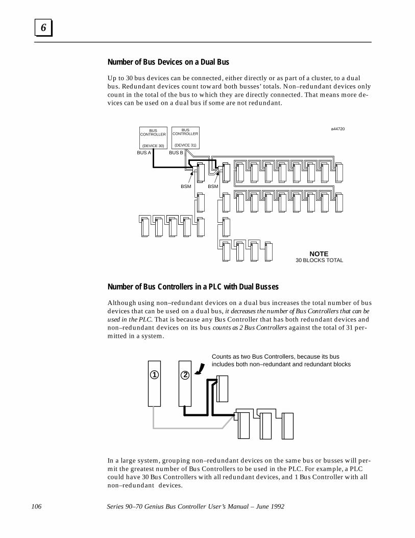
6
Series 90–70 Genius Bus Controller User’s Manual – June 1992106
Number of Bus Devices on a Dual Bus
Up to 30 bus devices can be connected, either directly or as part of a cluster, to a dualbus. Redundant devices count toward both busses’ totals. Non–redundant devices onlycount in the total of the bus to which they are directly connected. That means more de-vices can be used on a dual bus if some are not redundant.
BUS A
BUSCONTROLLER
(DEVICE 30)
BSM
a44720
NOTE30 BLOCKS TOTAL
BUS B
BUSCONTROLLER
(DEVICE 31)
BSM
Number of Bus Controllers in a PLC with Dual Busses
Although using non–redundant devices on a dual bus increases the total number of busdevices that can be used on a dual bus, it decreases the number of Bus Controllers that can beused in the PLC. That is because any Bus Controller that has both redundant devices andnon–redundant devices on its bus counts as 2 Bus Controllers against the total of 31 per-mitted in a system.
1 2
Counts as two Bus Controllers, because its busincludes both non–redundant and redundant blocks
In a large system, grouping non–redundant devices on the same bus or busses will per-mit the greatest number of Bus Controllers to be used in the PLC. For example, a PLCcould have 30 Bus Controllers with all redundant devices, and 1 Bus Controller with allnon–redundant devices.
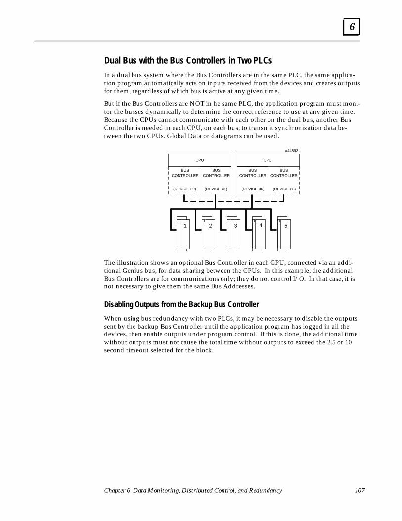
6
107Chapter 6 Data Monitoring, Distributed Control, and Redundancy
Dual Bus with the Bus Controllers in Two PLCsIn a dual bus system where the Bus Controllers are in the same PLC, the same applica-tion program automatically acts on inputs received from the devices and creates outputsfor them, regardless of which bus is active at any given time.
But if the Bus Controllers are NOT in he same PLC, the application program must moni-tor the busses dynamically to determine the correct reference to use at any given time.Because the CPUs cannot communicate with each other on the dual bus, another BusController is needed in each CPU, on each bus, to transmit synchronization data be-tween the two CPUs. Global Data or datagrams can be used.
4 5321
a44893
BUSCONTROLLER
CPU
(DEVICE 30)
BUSCONTROLLER
CPU
(DEVICE 31)
BUSCONTROLLER
(DEVICE 29)
BUSCONTROLLER
(DEVICE 28)
The illustration shows an optional Bus Controller in each CPU, connected via an addi-tional Genius bus, for data sharing between the CPUs. In this example, the additionalBus Controllers are for communications only; they do not control I/O. In that case, it isnot necessary to give them the same Bus Addresses.
Disabling Outputs from the Backup Bus Controller
When using bus redundancy with two PLCs, it may be necessary to disable the outputssent by the backup Bus Controller until the application program has logged in all thedevices, then enable outputs under program control. If this is done, the additional timewithout outputs must not cause the total time without outputs to exceed the 2.5 or 10second timeout selected for the block.

6
Series 90–70 Genius Bus Controller User’s Manual – June 1992108
Redundant Controllers
Redundant controllers provide backup controller protection for devices on a bus. Theredundant controllers can be in the same PLC (in the same rack or in different racks), orin two PLCs.
Bus Controller redundancy with one PLC provides protection against failure of the BusController.
Bus Controller redundancy with two PLCs, represented below, provides protectionagainst failure in the Bus Controller or elsewhere in the primary PLC.
a43558
BUSCONTROLLER
ÎCPU
(DEVICE 30)
4 5321
BUSCONTROLLER
ÎCPU
(DEVICE 31)
Synchronizing Dual CPUsSince bus devices broadcast their inputs to all CPUs on a bus, redundant Bus Controllersin separate PLCs need to maintain synchronization of their output data. Datagrams andGlobal Data can be used to synchronize the PLCs.
Either PLC can monitor the outputs of the other using the Outputs with Feedback fea-ture of discrete Genius I/O blocks. Since I/O blocks can monitor the actual state of theload and feed this state back to the PLC as input data, both PLCs can monitor the actualstate of all outputs.
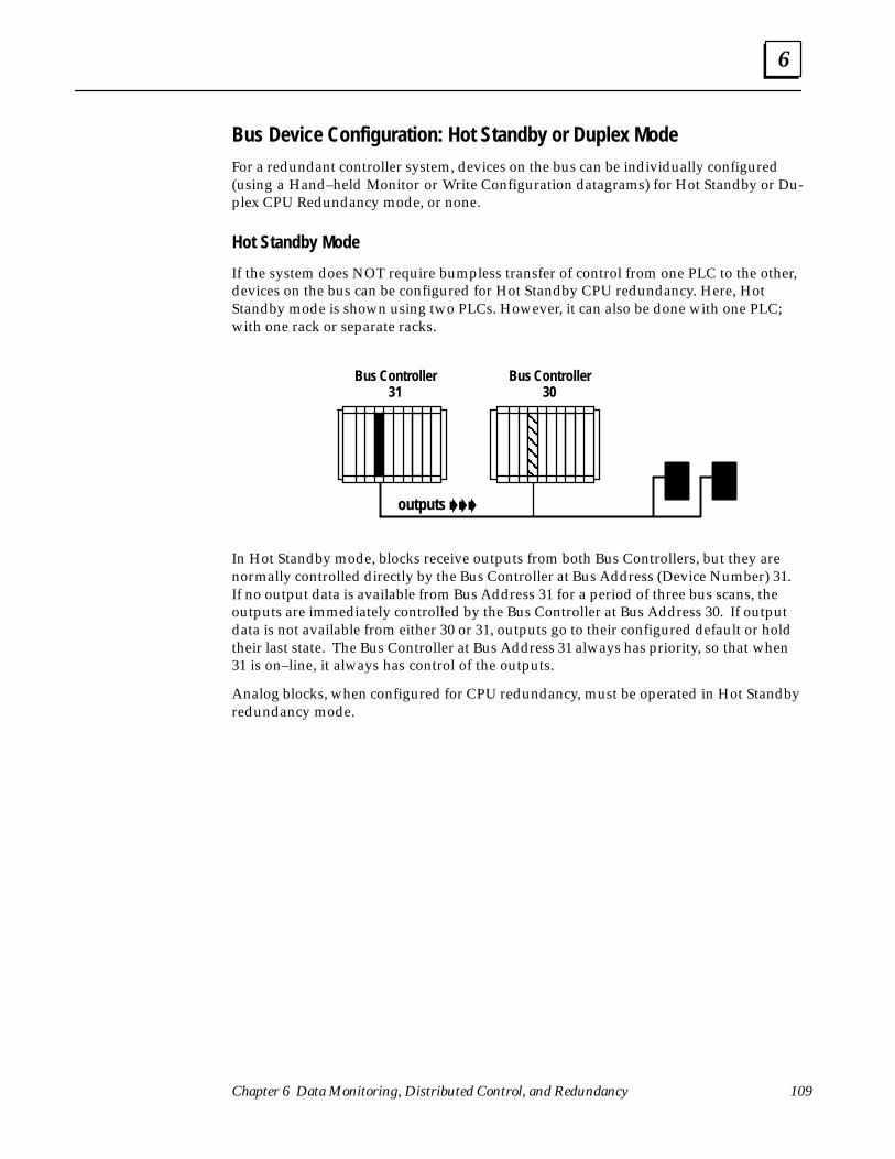
6
109Chapter 6 Data Monitoring, Distributed Control, and Redundancy
Bus Device Configuration: Hot Standby or Duplex ModeFor a redundant controller system, devices on the bus can be individually configured(using a Hand–held Monitor or Write Configuration datagrams) for Hot Standby or Du-plex CPU Redundancy mode, or none.
Hot Standby Mode
If the system does NOT require bumpless transfer of control from one PLC to the other,devices on the bus can be configured for Hot Standby CPU redundancy. Here, HotStandby mode is shown using two PLCs. However, it can also be done with one PLC;with one rack or separate racks.
ÇÇÇÇ
Bus Controller31
Bus Controller30
outputs ���
In Hot Standby mode, blocks receive outputs from both Bus Controllers, but they arenormally controlled directly by the Bus Controller at Bus Address (Device Number) 31.If no output data is available from Bus Address 31 for a period of three bus scans, theoutputs are immediately controlled by the Bus Controller at Bus Address 30. If outputdata is not available from either 30 or 31, outputs go to their configured default or holdtheir last state. The Bus Controller at Bus Address 31 always has priority, so that when31 is on–line, it always has control of the outputs.
Analog blocks, when configured for CPU redundancy, must be operated in Hot Standbyredundancy mode.
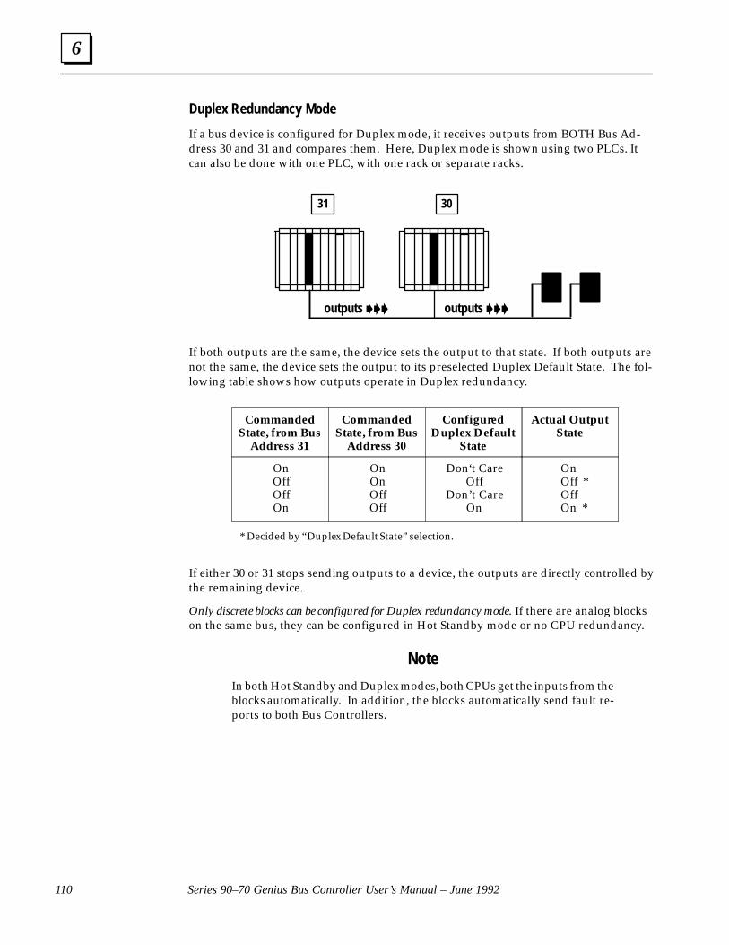
6
Series 90–70 Genius Bus Controller User’s Manual – June 1992110
Duplex Redundancy Mode
If a bus device is configured for Duplex mode, it receives outputs from BOTH Bus Ad-dress 30 and 31 and compares them. Here, Duplex mode is shown using two PLCs. Itcan also be done with one PLC, with one rack or separate racks.
31 30
outputs ��� outputs ���
If both outputs are the same, the device sets the output to that state. If both outputs arenot the same, the device sets the output to its preselected Duplex Default State. The fol-lowing table shows how outputs operate in Duplex redundancy.
CommandedState, from Bus
Address 31
CommandedState, from Bus
Address 30
ConfiguredDuplex Default
State
Actual OutputState
OnOffOffOn
OnOnOffOff
Don‘t CareOff
Don’t CareOn
OnOff *OffOn *
* Decided by “Duplex Default State” selection.
If either 30 or 31 stops sending outputs to a device, the outputs are directly controlled bythe remaining device.
Only discrete blocks can be configured for Duplex redundancy mode. If there are analog blockson the same bus, they can be configured in Hot Standby mode or no CPU redundancy.
Note
In both Hot Standby and Duplex modes, both CPUs get the inputs from theblocks automatically. In addition, the blocks automatically send fault re-ports to both Bus Controllers.

6
111Chapter 6 Data Monitoring, Distributed Control, and Redundancy
Dual Bus and Redundant ControllersThe two methods just described can be combined for dual bus and controller redundan-cy. A dual bus/dual controller system provides protection against failure in the bus trunkcable, the Bus Controller and the PLC. Through application programming, dual bus/dual controller redundancy can be implemented in two different ways:
A. For operation with both Hot Standby and Duplex devices on the bus. This applica-tion does NOT provide bumpless transfer of control.
B. For bumpless transfer of control as long as both Bus Controllers in the primary PLCare available (transfer is not bumpless between PLCs, however). This application isnot suitable for devices that must operate in Duplex CPU Redundancy mode.
Details of both types of application are given on the following pages.
Basic Operation of a Dual Bus/Dual Controller SystemBoth Bus Controllers in a given Series 90–70 PLC must use the same Bus Address (either30 or 31).
ÏÏÏÏÏÏÏÏ
a42472
BUS A
BUS B
BSM
BUSCONTROLLER
A(DEVICE 31)
CPU
BUSCONTROLLER
B(DEVICE 31)
CPU
BUSCONTROLLER
B(DEVICE 30)
BUSCONTROLLER
A(DEVICE 30)
1 2 3 4A 4B
BSM
In the example system represented above, both bus A and bus B operate in the sameway as a single bus, dual CPU system. Blocks 1, 2, and 3 interface to both PLCs via BusControllers 31(A) and 30(A) whenever the active bus is bus A, or via Bus Controllers31(B) and 30(B) whenever the active bus is bus B. Block 4(A) interfaces to both PLCs viaBus Controllers 31(A) and 30(A). Block 4(B) interfaces to both PLCs via Bus Controllers31(B) and 30(B).
Outputs
All four Bus Controllers are capable of sending outputs, although only outputs from theBus Controllers on the active bus are actually received. It may be necessary to disable theoutputs sent by the backup Bus Controller until the application program has logged inall the devices, then enable outputs under program control. If this is done, the addition-al time without outputs must not cause the total time without outputs to exceed the 2.5or 10 second timeout selected for the block.
Inputs and Diagnostics
Both Bus Controllers on the selected bus automatically receive all inputs and fault re-ports from any device on the bus that has been configured as being in “CPU Redundan-cy” mode.

6
Series 90–70 Genius Bus Controller User’s Manual – June 1992112
Bus and Controller Redundancy for Hot Standby DevicesWhen both PLCs provide outputs, and devices are configured for Hot Standby CPU Re-dundancy, the sequence of control in case of bus controller, bus, or PLC failure is:
primar y PLC, bus A� backup PLC, bus A
� primar y PLC, bus B
� backup PLC, bus B
Because the PLCs are operating independently, each time the control switches from onePLC to the other there may be a “bump” in the process. This may be of no consequencein some applications, and of significant consequence in others.
Normal Operation
In the default setup shown at left, during normal operation BusController 31A in the primary PLC controls all devices set up forHot Standby CPU redundancy.
Control Passes to Backup PLC on Bus A
If the device fails to receive valid output data from Bus Control-ler 31 for three bus scans, it will permit Bus Controller 30A tocontrol its outputs.
Control Passes to Bus B
If the device that controls bus switching stops receiving outputsfrom bus A for a period of three bus scans, it switches to bus B.Normal operation then resumes on bus B. Bus Controller 31Bcontrols (in the primary PLC) controls all devices set up for HotStandby CPU redundancy.
Control Passes to Backup PLC on Bus B
If the device fails to receive valid output data from Bus Control-ler 31 for three bus scans,it will permit Bus Controller 30B tocontrol its outputs.
31
ÇÇÇÇÇÇ
ÇÇÇ
ÇÇÇ
•
30A A BB
outputs �A
B
ÇÇÇ
ÇÇÇÇÇÇ
ÇÇÇ
•
31 30A A BB
outputs �
A
B
outputs �
ÇÇÇÇ
ÇÇÇÇ
ÇÇÇÇ
•
31 30A A BB
A
B
ÇÇÇÇ
ÇÇÇÇ
ÇÇÇÇ
•
31 30A A BB
outputs �
A
B

6
113Chapter 6 Data Monitoring, Distributed Control, and Redundancy
Bus and Controller Redundancy for Duplex DevicesIf the application requires that bus devices operate in Duplex CPU Redundancy mode,outputs must be enabled to both the primary and the backup PLC. The sequence of con-trol in case of Bus Controller, bus, or PLC failure is:
control shared by Bus Controllers 31 and 30 on bus A� Bus Controller 30, bus A � control shared by Bus Controllers 31 and 30 on bus B� Bus Controller 30, bus B
Because the PLCs are operating independently, each time the control switches from onePLC to the other there may be a “bump” in the process. This may be of no consequencein some applications, and of significant consequence in others.
Normal Operation
In the default setup shown at left, during normal operation BusControllers 31A and 30A jointly control any devices set up forDuplex CPU redundancy.
Devices Controlled by Bus Controller 30 on Bus A
If a duplex device fails to receive output data from Bus Control-ler 31A for three bus scans, it will permit Bus Controller 30A tocontrol its outputs.
Control Passes to Bus B
If the device that controls bus switching stops receiving outputsfrom bus A for a period of three bus scans, it switches to bus B.Normal operation then resumes on bus B. Bus Controllers 31Band 30B jointly control any devices set up for Duplex CPU re-dundancy.
Control Passes to Backup PLC on Bus B
If a duplex device fails to receive output data from Bus Control-ler 31B for three bus scans, it will permit Bus Controller 30B tocontrol its outputs.
ÇÇÇ
ÇÇÇÇÇÇ
•
31 30A A BB
outputs � outputs �A
B
ÇÇÇ
ÇÇÇ
ÇÇÇÇÇÇ
•
31 30A A BB
outputs �
A
B
outputs �
ÇÇÇ
ÇÇÇ
•
31 30A A BB
outputs �
A
B
ÇÇÇ
ÇÇÇ
ÇÇÇ
•
A A BB
outputs �
A
B
31 30
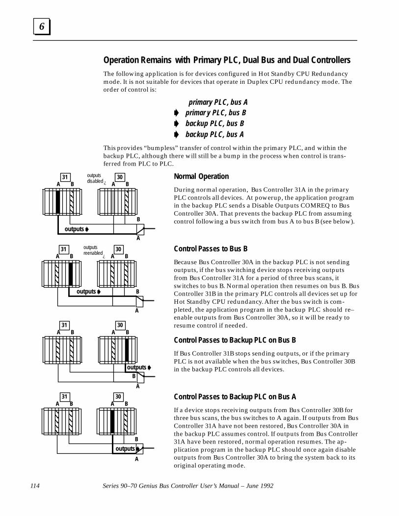
6
Series 90–70 Genius Bus Controller User’s Manual – June 1992114
Operation Remains with Primary PLC, Dual Bus and Dual ControllersThe following application is for devices configured in Hot Standby CPU Redundancymode. It is not suitable for devices that operate in Duplex CPU redundancy mode. Theorder of control is:
primary PLC, bus A� primar y PLC, bus B� backup PLC, bus B� backup PLC, bus A
This provides “bumpless” transfer of control within the primary PLC, and within thebackup PLC, although there will still be a bump in the process when control is trans-ferred from PLC to PLC.
Normal Operation
During normal operation, Bus Controller 31A in the primaryPLC controls all devices. At powerup, the application programin the backup PLC sends a Disable Outputs COMREQ to BusController 30A. That prevents the backup PLC from assumingcontrol following a bus switch from bus A to bus B (see below).
Control Passes to Bus B
Because Bus Controller 30A in the backup PLC is not sendingoutputs, if the bus switching device stops receiving outputsfrom Bus Controller 31A for a period of three bus scans, itswitches to bus B. Normal operation then resumes on bus B. BusController 31B in the primary PLC controls all devices set up forHot Standby CPU redundancy. After the bus switch is com-pleted, the application program in the backup PLC should re–enable outputs from Bus Controller 30A, so it will be ready toresume control if needed.
Control Passes to Backup PLC on Bus B
If Bus Controller 31B stops sending outputs, or if the primaryPLC is not available when the bus switches, Bus Controller 30Bin the backup PLC controls all devices.
Control Passes to Backup PLC on Bus A
If a device stops receiving outputs from Bus Controller 30B forthree bus scans, the bus switches to A again. If outputs from BusController 31A have not been restored, Bus Controller 30A inthe backup PLC assumes control. If outputs from Bus Controller31A have been restored, normal operation resumes. The ap-plication program in the backup PLC should once again disableoutputs from Bus Controller 30A to bring the system back to itsoriginal operating mode.
ÇÇÇÇÇÇ
ÇÇÇ
•
31 30A A BB
outputs �A
B
outputsdisabled ¿
outputs �
ÇÇÇ
ÇÇÇ
ÇÇÇ
•
31 30A A BB
A
B
outputsreenabled¿
ÇÇÇÇ
ÇÇÇÇÇÇÇÇ
ÇÇÇÇ
•
31 30A A BB
outputs �
A
B
ÇÇÇÇ
ÇÇÇÇÇÇÇÇ
ÇÇÇÇ
•
31 30A A BB
outputs �
A
B
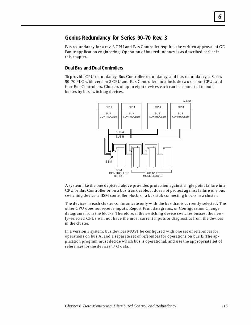
6
115Chapter 6 Data Monitoring, Distributed Control, and Redundancy
Genius Redundancy for Series 90–70 Rev. 3Bus redundancy for a rev. 3 CPU and Bus Controller requires the written approval of GEFanuc application engineering. Operation of bus redundancy is as described earlier inthis chapter.
Dual Bus and Dual Controllers
To provide CPU redundancy, Bus Controller redundancy, and bus redundancy, a Series90–70 PLC with version 3 CPU and Bus Controller must include two or four CPUs andfour Bus Controllers. Clusters of up to eight devices each can be connected to bothbusses by bus switching devices.
BUSCONTROLLER
CPUCPU
ÏÏÏÏÏÏÏÏÏÏÏÏ
a43457
BUS A
BUS B
UP TO 7 MORE BLOCKS
BSM
BSMCONTROLLER
BLOCK
ÏÏÏÏÏÏÏÏÏÏÏÏ
ÏÏÏÏÏÏÏÏÏÏÏÏ
BUSCONTROLLER
BUSCONTROLLER
CPU
BUSCONTROLLER
CPU
A system like the one depicted above provides protection against single point failure in aCPU or Bus Controller or on a bus trunk cable. It does not protect against failure of a busswitching device, a BSM controller block, or a bus stub connecting blocks in a cluster.
The devices in each cluster communicate only with the bus that is currently selected. Theother CPU does not receive inputs, Report Fault datagrams, or Configuration Changedatagrams from the blocks. Therefore, if the switching device switches busses, the new-ly–selected CPUs will not have the most current inputs or diagnostics from the devicesin the cluster.
In a version 3 system, bus devices MUST be configured with one set of references foroperations on bus A, and a separate set of references for operations on bus B. The ap-plication program must decide which bus is operational, and use the appropriate set ofreferences for the devices’ I/O data.
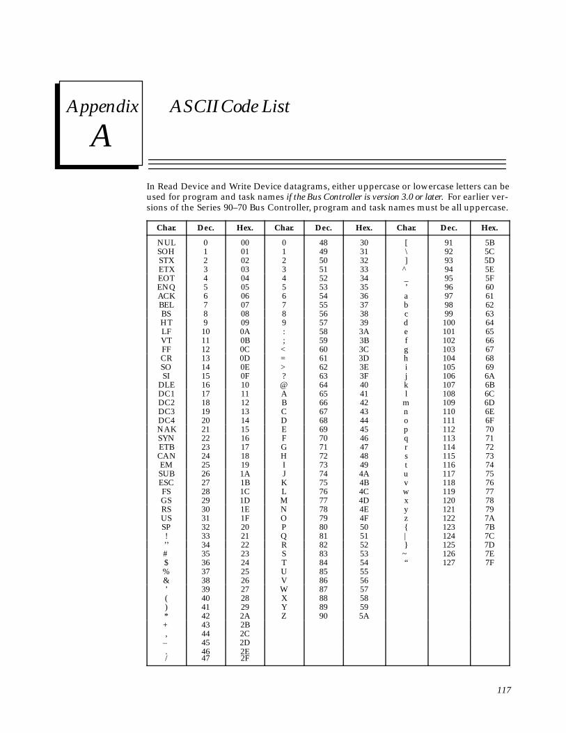
Asection level 1 1figure_ap level 1 table_ap level 1
117
Appendix A ASCII Code List
In Read Device and Write Device datagrams, either uppercase or lowercase letters can beused for program and task names if the Bus Controller is version 3.0 or later. For earlier ver-sions of the Series 90–70 Bus Controller, program and task names must be all uppercase.
Char. Dec. Hex. Char. Dec. Hex. Char. Dec. Hex.
NUL 0 00 0 48 30 [ 91 5BSOH 1 01 1 49 31 \ 92 5CSTX 2 02 2 50 32 ] 93 5DETX 3 03 3 51 33 ^ 94 5EEOT 4 04 4 52 34 _ 95 5FENQ 5 05 5 53 35 ’ 96 60ACK 6 06 6 54 36 a 97 61BEL 7 07 7 55 37 b 98 62BS 8 08 8 56 38 c 99 63HT 9 09 9 57 39 d 100 64LF 10 0A : 58 3A e 101 65VT 11 0B ; 59 3B f 102 66FF 12 0C < 60 3C g 103 67CR 13 0D = 61 3D h 104 68SO 14 0E > 62 3E i 105 69SI 15 0F ? 63 3F j 106 6A
DLE 16 10 @ 64 40 k 107 6BDC1 17 11 A 65 41 l 108 6CDC2 18 12 B 66 42 m 109 6DDC3 19 13 C 67 43 n 110 6EDC4 20 14 D 68 44 o 111 6FNAK 21 15 E 69 45 p 112 70SYN 22 16 F 70 46 q 113 71ETB 23 17 G 71 47 r 114 72CAN 24 18 H 72 48 s 115 73EM 25 19 I 73 49 t 116 74SUB 26 1A J 74 4A u 117 75ESC 27 1B K 75 4B v 118 76FS 28 1C L 76 4C w 119 77GS 29 1D M 77 4D x 120 78RS 30 1E N 78 4E y 121 79US 31 1F O 79 4F z 122 7ASP 32 20 P 80 50 { 123 7B! 33 21 Q 81 51 | 124 7C’’ 34 22 R 82 52 } 125 7D# 35 23 S 83 53 ~ 126 7E$ 36 24 T 84 54 “ 127 7F% 37 25 U 85 55& 38 26 V 86 56’ 39 27 W 87 57( 40 28 X 88 58) 41 29 Y 89 59* 42 2A Z 90 5A+ 43 2B, 44 2C
– 45 2D./
4647
2E2F
Index
118
AAD Comm fault, 60
Add. of Bus Controller fault, 60
Addition of Block fault, 60
Addition of Bus Controller status refer-ence, 54
Addition of I/O Module status reference,54
Addition of Rack status reference, 54
AI Hi/Low Alarm fault, 59
AI Under/Overrange fault, 59
Alarm Contacts, 56
Analog Data Format, 6 , 27
Analog faults, 59
AQ Under/Overrange fault, 59
Assign Monitor COMREQ, 63 , 67 , 80
Assigned Monitor, 31
BBaud Rate, 4 , 17
Bit or Byte mode for memory–access da-tagrams, 87
BusConfiguration, 24 Connection to, 13 Continuity, 14 Length, 4 Terminating, 14 Type, 4
Bus Address, 17
Bus ControllerConfiguration, 16 , 35 Description, 3 Installation, 12 Number in System, 1 Operation, 5 Removal, 12 Version required for redundancy, 21
Bus Controller configuration examples, 39
Bus Controller Fault status reference, 54
BUS CONTROLLER software fault, 61
Bus Error Rate, 58
Bus fault, 60
Bus Fault status reference, 54
Bus Interface Modules, 34
Bus Out Disable fault, 60
Bus Scan, 5 , 92
Bus Scan Time, 95
CCal Mem fault, 60
Catalog Number, 1
Circuit Faults, 59
Circuit Number, 57
Clear All Circuit Faults COMREQ, 63 , 67 ,79
Clear Circuit Fault COMREQ, 63 , 67 , 79
Command Block, 73 , 89
Communication Request Commands, 63
COMREQ, 63 Command Block, 65 Command Numbers, 66 Commands
Assign Monitor, 67 , 80 Clear All Circuit Faults, 67 , 79 Clear Circuit Fault, 67 , 79 Dequeue Datagram, 67 , 91 Global Data Enable, 67 , 83 I/O Fault Categories Enable, 98 I/O Faults Enable, 67 Outputs Enabled, 67 , 82 Pulse Test, 67 , 75 Read Configuration, 67 , 76 Read Device, 67 , 85 Read Diagnostics, 67 , 78 Request Datagram Reply, 67 , 97 Send Datagram, 67 , 94 Switch BSM, 67 , 84 Write Configuration, 67 , 77 Write Device, 67 , 90
Examples, 72 , 73 Outputs, 69 Program Instruction, 68 Quick Reference, 67 Status, 71 Status Block, 70 Status Pointer, 65
COMREQs and Passwords, Allowablepassword levels, 63

Index
119
Config Mem fault, 60
Configuration, 15 Bus Controller, 16 , 35 Devices on bus, 24 Generic I/O Device, 38 Global Data, 18 , 35 High–speed Counter, 36 I/O blocks, 25 Other devices, 34 PCIM, QBIM, 35 PowerTRAC Block, 37 Remote I/O Scanner, 33
Configuration mismatch reference, 54
Connection to the Bus, 13
CPU Redundancy, 108
CPU Sweep, 92 , 95
CS Feedback Error fault, 59
DData Monitoring, 31 , 100
Data quantities, 2
Datagram Priority, 95
Datagrams, 8 , 66 Incoming, 74 , 92 Number per CPU Sweep, 95 Priority, 94 Ways to Send, 74 , 94
Dequeue Datagram Command, 91
Dequeue Datagram COMREQ, 67
Device Number, 17 , 24
Device Number selection, 33
DG Queue fault, 61
Diagnostics, 7 , 15 , 53 , 100
Disable Outputs, 30 , 31
Discrete faults, 59
Distributed Control, 30
Dual Bus, configuration, 22
EEnable/Disable Global Data COMREQ, 63
, 83
Enable/Disable Outputs COMREQ, 63 , 82
Errors, number on bus, 17
Excessive faults, 61
External GBC, redundant, configuration,23
Extra Block fault, 61
FFault
Category, 57 Contacts, 55 Description, 57 Location, 57 Type, 57
Fault Clearing, 58
Fault Identification Reference, 59
Fault Locating References, 55
Fault Logged, status reference, 54
Fault Reports, disable sending to CPU, 98
Fault Table, 57
Faults, number of, 58
Forced/Unforced Circuit fault, 61
Fuse Blown fault, 59 , 60
GGBC Software Exception fault, 61
GENA faults, 59
Generic I/O Device, configuration, 38
Genius blocks, 1 , 2
Genius Bus Scan, 5
Global Data, 90 %G memory for, 18 , 20 Automatic configuration, 18 Configuration, 18 , 35 Length, 18 Receiving, 35

Index
120
Reference for another host type, 18 Series 90–70 PLC, 9
Global Data Enable COMREQ, 67 , 83
HHand–held Monitor, 1
Compatibility, 3 Connector on Bus Controller, 3
Headend fault, 60
HIgh Error Rate fault, 61
High–speed Counter, 26
High–speed Counter, configuration, 36
II/O block configuration, 25
I/O Blocks, 1 , 2
I/O bus fault, 60
I/O data, 2
I/O Fault Categories Enable COMREQ, 67, 98
I/O Fault Table capacity, 58
I/O Module Fault status reference, 54
I/O Table Full, status reference, 54
Input Short fault, 59
Inputs, Monitoring, 100
Inputs and Outputs, 5 , 6 , 27
Install the Bus Controller, 12
Internal fault, 59
Internal GBC, redundant, configuration,23
Intrnal Ckt fault, 60
Isolation, 4
JJumpers on Terminal Assembly, 14
LLEDs
Channel OK, 3 , 17 I/O Enabled, blocks, 30 Module OK, 3
LL Analog Faults, 59
Logicmaster 90 software, version requiredfor redundancy, 21
Loss of Block fault, 58 , 60
Loss of BUS CONTROLLER fault, 61
Loss of Bus Controller status reference, 54
Loss of I/O Module status reference, 54
Loss of or Missing IOC fault, 23
Loss of Rack status reference, 54
Loss Power fault, 59
LP Mail Rejected fault, 61
MMemory for Global Data, 18 , 20
Memory for I/O Blocks, 2 , 26
Memory for Read/Write Device, 86
Modulation technique, 4
Module Description, 3
Monitoring, 100
NNo Fault contacts, 55
No Load fault, 59
Not Spec fault, 60
OOpen Wire fault, 59
Outputs, Disable, 30 , 31 , 38
Outputs Enable COMREQ, 67 , 82
Over Temp fault, 59
Overload fault, 59
PPaired GBC, configuration, 23

Index
121
Passwords, Levels suitable for COMREQs,63
PCIMConfiguration, 35 Receiving Global Data, 9
Point fault, 59 , 60
PowerTRAC Block, configuration, 37
Priority, 95
Programming for a COMREQ, 64
Pulse Test COMREQ, 63 , 67 , 75
QQBIM
Configuration, 35 Receiving Global Data, 9
RRead Configuration COMREQ, 63 , 67 , 76
Read Configuration Datagram, 97
Read Data Datagram, 97
Read Device COMREQ, 63 , 67 , 85
Read Device Datagram, 97
Read Diagnostics COMREQ, 63 , 67 , 78
Read Diagnostics Datagram, 97
Redundancy, 32 , 102 configuration, 21 configuration examples, 40 , 42 , 44 , 46 ,
48 , 50 configuration instructions, 21
Redundancy Mode, configuration, 21 , 22
Redundancy, references for, 27
Redundant control, configuration, 22
Reference Address, 26 , 57
References, not used, 2
References, status, 54
Remote Drop, 1 , 33
Remote I/O Scanner, 33
Remove the Bus Controller, 12
Request Datagram Reply COMREQ, 67 ,97
RW Queue Full fault, 61
SSBA conflict fault, 60
Send Datagram COMREQ, 67 , 94
Series 90–70 PLC, version required for re-dundancy, 21
Series 90–70 PLC Global Data Operation,9
Share RAM fault, 60
Short Circuit fault, 59
Signal/noise ratio, 4
Software Failure status reference, 54
Status LEDs, 3
Status of COMREQ, 71
Subfunction Code, 74 , 97
Switch BSM COMREQ, 63 , 67 , 84
Switch Fault fault, 59
Switching time, of redundant bus, config-uration, 23
System Status references, 54
TTerminating the Bus, 14
Timing, Bus scan and CPU sweep, 95
Token passing, 5
Too Many Bus Controllers, status refer-ence, 54
UUser Scaling Error fault, 60
WWD Timeout fault, 60
Wiring Error fault, 59
Write Configuration COMREQ, 63 , 67 , 77
Write Device COMREQ, 63 , 67 , 90