ge fanuc control - hillaryllc.comhillaryllc.com/index_htm_files/ge_fanuc_maintenance_manual.pdf ·...
TRANSCRIPT

FANUC MAINTENANCE MANUAL
GE FANUC CONTROL MAINTENANCE MANUAL
FADAL MACHINING CENTERS, LLC
Corporate Office ...................................... phone (818) 407-1400............................. fax (818) 407-0020Service / Parts ......................................... phone (818) 727-2100............................. fax (818) 407-1004Programming Support ............................. phone (818) 727-2100............................. fax (818) 407-0061
[email protected] Plummer Street, Chatsworth, California 91311 USA

AUGUST 2005
FADAL MACHINING CENTERS
FANUC MAINTENANCE MANUAL
TABLE OF CONTENTS
1.0 SPECIFICATIONS . . . . . . . . . . . . . . . . . . . . . . . . . . . . . . . . . . . . . . . . . . . . . . . . . . . . . . . . . . . . . . . . . . . 1
1.1 ILLUSTRATIONS & DATA FOR ALL VMC MODELS . . . . . . . . . . . . . . . . . . . . . . . . . . . . . . . . . . . . . . .21.1.1 VMC 2216 . . . . . . . . . . . . . . . . . . . . . . . . . . . . . . . . . . . . . . . . . . . . . . . . . . . . . . . . . . . . . . . . . . . . . . . . . . . . . . . . . . . . . . 21.1.2 VMC 3016. . . . . . . . . . . . . . . . . . . . . . . . . . . . . . . . . . . . . . . . . . . . . . . . . . . . . . . . . . . . . . . . . . . . . . . . . . . . . . . . . . . . . . 41.1.3 VMC 4020 . . . . . . . . . . . . . . . . . . . . . . . . . . . . . . . . . . . . . . . . . . . . . . . . . . . . . . . . . . . . . . . . . . . . . . . . . . . . . . . . . . . . . . 61.1.4 VMC 6030 . . . . . . . . . . . . . . . . . . . . . . . . . . . . . . . . . . . . . . . . . . . . . . . . . . . . . . . . . . . . . . . . . . . . . . . . . . . . . . . . . . . . . . 81.1.5 VMC 8030 . . . . . . . . . . . . . . . . . . . . . . . . . . . . . . . . . . . . . . . . . . . . . . . . . . . . . . . . . . . . . . . . . . . . . . . . . . . . . . . . . . . . . .101.1.6 VMC 3020 . . . . . . . . . . . . . . . . . . . . . . . . . . . . . . . . . . . . . . . . . . . . . . . . . . . . . . . . . . . . . . . . . . . . . . . . . . . . . . . . . . . . . .121.1.7 VMC 4525 . . . . . . . . . . . . . . . . . . . . . . . . . . . . . . . . . . . . . . . . . . . . . . . . . . . . . . . . . . . . . . . . . . . . . . . . . . . . . . . . . . . . . .141.1.8 VMC 6535 . . . . . . . . . . . . . . . . . . . . . . . . . . . . . . . . . . . . . . . . . . . . . . . . . . . . . . . . . . . . . . . . . . . . . . . . . . . . . . . . . . . . . .16
1.2 FADAL BOLT TORQUE SPECIFICATIONS . . . . . . . . . . . . . . . . . . . . . . . . . . . . . . . . . . . . . . . . . . . . . 181.2.1 2216 & 3016 TABLE . . . . . . . . . . . . . . . . . . . . . . . . . . . . . . . . . . . . . . . . . . . . . . . . . . . . . . . . . . . . . . . . . . . . . . . . . . . . . .191.2.2 3020 & 4525 TABLE . . . . . . . . . . . . . . . . . . . . . . . . . . . . . . . . . . . . . . . . . . . . . . . . . . . . . . . . . . . . . . . . 201.2.3 4020 TABLE . . . . . . . . . . . . . . . . . . . . . . . . . . . . . . . . . . . . . . . . . . . . . . . . . . . . . . . . . . . . . . . . . . . . . 211.2.4 6030 TABLE . . . . . . . . . . . . . . . . . . . . . . . . . . . . . . . . . . . . . . . . . . . . . . . . . . . . . . . . . . . . . . . . . . . . . 221.2.5 8030 TABLE . . . . . . . . . . . . . . . . . . . . . . . . . . . . . . . . . . . . . . . . . . . . . . . . . . . . . . . . . . . . . . . . . . . . . 231.2.6 6535 TABLE . . . . . . . . . . . . . . . . . . . . . . . . . . . . . . . . . . . . . . . . . . . . . . . . . . . . . . . . . . . . . . . . . . . . . . . . . . . . . . . . . . . .241.2.7 T-SLOTS FOR ALL TABLES. . . . . . . . . . . . . . . . . . . . . . . . . . . . . . . . . . . . . . . . . . . . . . . . . . . . . . . . . . . 25
1.3 RECOMMENDED MAINLINE FUSES / CIRCUIT BREAKERS . . . . . . . . . . . . . . . . . . . . . . . . . . . . . . 26
2.0 PRE-INSTALLATION PROCEDURES . . . . . . . . . . . . . . . . . . . . . . . . . . . . . . . . . . . . . . . . . . . . . . . . . . . 27
2.1 FOUNDATION . . . . . . . . . . . . . . . . . . . . . . . . . . . . . . . . . . . . . . . . . . . . . . . . . . . . . . . . . . . . . . . . . . . . 28
2.2 SHIPPING DIMENSIONS . . . . . . . . . . . . . . . . . . . . . . . . . . . . . . . . . . . . . . . . . . . . . . . . . . . . . . . . . . . 32
2.3 POSITIONING . . . . . . . . . . . . . . . . . . . . . . . . . . . . . . . . . . . . . . . . . . . . . . . . . . . . . . . . . . . . . . . . . . . . 33
2.4 AIR SUPPLY . . . . . . . . . . . . . . . . . . . . . . . . . . . . . . . . . . . . . . . . . . . . . . . . . . . . . . . . . . . . . . . . . . . . . 34
2.5 ELECTRICAL GROUNDING . . . . . . . . . . . . . . . . . . . . . . . . . . . . . . . . . . . . . . . . . . . . . . . . . . . . . . . . . 352.5.1 PRIMARY GROUNDING . . . . . . . . . . . . . . . . . . . . . . . . . . . . . . . . . . . . . . . . . . . . . . . . . . . . . . . . . . . . . 352.5.2 SUPPLEMENTAL GROUNDING . . . . . . . . . . . . . . . . . . . . . . . . . . . . . . . . . . . . . . . . . . . . . . . . . . . . . . . . 35
2.6 CHECKING GROUNDING INTEGRITY OF FADAL VMCS. . . . . . . . . . . . . . . . . . . . . . . . . . . . . . . . . . 372.6.1 SPECIFICATION -GROUNDING FOR THE FADAL MACHINE . . . . . . . . . . . . . . . . . . . . . . . . . . . . . . . . . . . . . . . . . . . . .372.6.2 INSPECTION - CHECK GROUND WIRE COMING INTO VMC . . . . . . . . . . . . . . . . . . . . . . . . . . . . . . . . . . . . 372.6.3 VERIFICATION - CHECK GROUNDING INTEGRITY WITH FLUKE METER . . . . . . . . . . . . . . . . . . . . . . . . . . . . 372.6.4 ELECTRICAL SERVICE . . . . . . . . . . . . . . . . . . . . . . . . . . . . . . . . . . . . . . . . . . . . . . . . . . . . . . . . . . . . . . 382.6.5 PREFERRED SERVICE . . . . . . . . . . . . . . . . . . . . . . . . . . . . . . . . . . . . . . . . . . . . . . . . . . . . . . . . . . . . . . . . . . . . . . . . . . .382.6.6 ALTERNATE SERVICE . . . . . . . . . . . . . . . . . . . . . . . . . . . . . . . . . . . . . . . . . . . . . . . . . . . . . . . . . . . . . . 382.6.7 WIRING . . . . . . . . . . . . . . . . . . . . . . . . . . . . . . . . . . . . . . . . . . . . . . . . . . . . . . . . . . . . . . . . . . . . . . . . 39
AUGUST 2005 TABLE OF CONTENTS i
FADAL MACHINING CENTERS
2.6.8 CONDUIT . . . . . . . . . . . . . . . . . . . . . . . . . . . . . . . . . . . . . . . . . . . . . . . . . . . . . . . . . . . . . . . . . . . . . . . 40
3.0 INSTALLATION PROCEDURE . . . . . . . . . . . . . . . . . . . . . . . . . . . . . . . . . . . . . . . . . . . . . . . . . . . . . . . . . 41
3.1 MACHINE INSTALLATION & HOOK-UP . . . . . . . . . . . . . . . . . . . . . . . . . . . . . . . . . . . . . . . . . . . . . . . . 423.1.1 UNPACKING . . . . . . . . . . . . . . . . . . . . . . . . . . . . . . . . . . . . . . . . . . . . . . . . . . . . . . . . . . . . . . . . . . . . . . . . . . . . . . . . . . . 423.1.2 PLACING THE VMC . . . . . . . . . . . . . . . . . . . . . . . . . . . . . . . . . . . . . . . . . . . . . . . . . . . . . . . . . . . . . . . . . 423.1.3 AIR SUPPLY . . . . . . . . . . . . . . . . . . . . . . . . . . . . . . . . . . . . . . . . . . . . . . . . . . . . . . . . . . . . . . . . . . . . . . . . . . . . . . . . . . . 433.1.4 POWER CHECK . . . . . . . . . . . . . . . . . . . . . . . . . . . . . . . . . . . . . . . . . . . . . . . . . . . . . . . . . . . . . . . . . . .44
3.2 TRANSFORMER TAPPING . . . . . . . . . . . . . . . . . . . . . . . . . . . . . . . . . . . . . . . . . . . . . . . . . . . . . . . . . . 48
3.3 SINGLE PHASE INPUT POWER . . . . . . . . . . . . . . . . . . . . . . . . . . . . . . . . . . . . . . . . . . . . . . . . . . . . . 49
3.4 PHASE CONVERTER ROTARY . . . . . . . . . . . . . . . . . . . . . . . . . . . . . . . . . . . . . . . . . . . . . . . . . . . . . . 50
3.5 LEVELING . . . . . . . . . . . . . . . . . . . . . . . . . . . . . . . . . . . . . . . . . . . . . . . . . . . . . . . . . . . . . . . . . . . . . . . 513.5.1 FOR ALL BOX WAY VMCS . . . . . . . . . . . . . . . . . . . . . . . . . . . . . . . . . . . . . . . . . . . . . . . . . . . . . . . . . . . . 51
3.6 HOLD DOWN CLAMPS . . . . . . . . . . . . . . . . . . . . . . . . . . . . . . . . . . . . . . . . . . . . . . . . . . . . . . . . . . . . . 54
3.7 OPTICAL FIBER CABLE HANDLING . . . . . . . . . . . . . . . . . . . . . . . . . . . . . . . . . . . . . . . . . . . . . . . . . . 55
3.8 COUPLER INSTALLATION ON AXIS MOTOR OR BALLSCREW . . . . . . . . . . . . . . . . . . . . . . . . . . . . 56
3.9 PENDANT INSTALLATION . . . . . . . . . . . . . . . . . . . . . . . . . . . . . . . . . . . . . . . . . . . . . . . . . . . . . . . . . . 59
3.10 GENERAL . . . . . . . . . . . . . . . . . . . . . . . . . . . . . . . . . . . . . . . . . . . . . . . . . . . . . . . . . . . . . . . . . . . . . .62
3.11 CHIP CONVEYOR . . . . . . . . . . . . . . . . . . . . . . . . . . . . . . . . . . . . . . . . . . . . . . . . . . . . . . . . . . . . . . . . 633.11.1 INSTALLATION PROCEDURE . . . . . . . . . . . . . . . . . . . . . . . . . . . . . . . . . . . . . . . . . . . . . . . . . . . . . . . . . . . . . . . . . . . 633.11.2 CHIP CONVEYOR POWER AND CONTROLS. . . . . . . . . . . . . . . . . . . . . . . . . . . . . . . . . . . . . . . . . . . . . . . . . . . . . . . 64
4.0 MACHINE MAINTENANCE . . . . . . . . . . . . . . . . . . . . . . . . . . . . . . . . . . . . . . . . . . . . . . . . . . . . . . . . . . . . 67
4.1 SCHEDULED MAINTENANCE . . . . . . . . . . . . . . . . . . . . . . . . . . . . . . . . . . . . . . . . . . . . . . . . . . . . . . . 684.1.1 MAINTENANCE & LUBRICATION SCHEDULE . . . . . . . . . . . . . . . . . . . . . . . . . . . . . . . . . . . . . . . . . . . . . . . 684.1.2 LUBRICATION OF THE WAYS . . . . . . . . . . . . . . . . . . . . . . . . . . . . . . . . . . . . . . . . . . . . . . . . . . . . . . . . . . . . . . . . . . . . 694.1.3 COOLING FANS . . . . . . . . . . . . . . . . . . . . . . . . . . . . . . . . . . . . . . . . . . . . . . . . . . . . . . . . . . . . . . . . . . . . . . . . . . . . . . . . 704.1.4 SPINDLE & BALLSCREW COOLING SYSTEM . . . . . . . . . . . . . . . . . . . . . . . . . . . . . . . . . . . . . . . . . . . . . . . . . . . . . . . . 714.1.5 PUMP FILTER . . . . . . . . . . . . . . . . . . . . . . . . . . . . . . . . . . . . . . . . . . . . . . . . . . . . . . . . . . . . . . . . . . . . 714.1.6 TANK RESERVOIR . . . . . . . . . . . . . . . . . . . . . . . . . . . . . . . . . . . . . . . . . . . . . . . . . . . . . . . . . . . . . . . . . 724.1.7 FLUIDS . . . . . . . . . . . . . . . . . . . . . . . . . . . . . . . . . . . . . . . . . . . . . . . . . . . . . . . . . . . . . . . . . . . . . . . . . . . . . . . . . . . . . . . 734.1.8 DUAL ARM TOOL CHANGER . . . . . . . . . . . . . . . . . . . . . . . . . . . . . . . . . . . . . . . . . . . . . . . . . . . . . . . . . . . . . . . . . . . . . 744.1.9 SCHEDULED MAINTENANCE FOR DUAL ARM TOOL CHANGER . . . . . . . . . . . . . . . . . . . . . . . . . . . . . . . . . . . . . . . . 74
4.2 TESTS FOR CE SAFEGUARDS ON FADAL MACHINES . . . . . . . . . . . . . . . . . . . . . . . . . . . . . . . . . . 76
4.3 CHIP CONVEYOR . . . . . . . . . . . . . . . . . . . . . . . . . . . . . . . . . . . . . . . . . . . . . . . . . . . . . . . . . . . . . . . . . 784.3.1 MAINTENANCE SCHEDULE CHIP CONVEYOR . . . . . . . . . . . . . . . . . . . . . . . . . . . . . . . . . . . . . . . . . . . . . . . . . . . . . . 784.3.2 STOPPING THE CHIP CONVEYOR ON US AND CE MACHINES . . . . . . . . . . . . . . . . . . . . . . . . . . . . . . . . . . . . . . . . . 79
ii TABLE OF CONTENTS MAN-0121 R1
FANUC MAINTENANCE MANUAL
4.3.3 RESTARTING THE CHIP CONVEYOR . . . . . . . . . . . . . . . . . . . . . . . . . . . . . . . . . . . . . . . . . . . . . . . . . . . . . . . . . . . . . . . 794.3.4 OBSERVANCE AND INSPECTION . . . . . . . . . . . . . . . . . . . . . . . . . . . . . . . . . . . . . . . . . . . . . . . . . . . . . . . . . . . . . . . . . . 79
5.0 FANUC CONTROL . . . . . . . . . . . . . . . . . . . . . . . . . . . . . . . . . . . . . . . . . . . . . . . . . . . . . . . . . . . . . . . . . . 81
5.1 SCREEN DISPALYED IMMEDIATELY AFTER POWER IS TURNED ON . . . . . . . . . . . . . . . . . . . . . . 825.1.1 SLOT STATUS DISPLAY . . . . . . . . . . . . . . . . . . . . . . . . . . . . . . . . . . . . . . . . . . . . . . . . . . . . . . . . . . . . . . . . . . . . . . . . . . 825.1.2 SETTING MODULE SCREEN . . . . . . . . . . . . . . . . . . . . . . . . . . . . . . . . . . . . . . . . . . . . . . . . . . . . . . . . . . . . . . . . . . . . . . 835.1.3 CONFIGURATION DISPLAY OF SOFTWARE . . . . . . . . . . . . . . . . . . . . . . . . . . . . . . . . . . . . . . . . . . . . . . . . . . . . . . . . . 84
5.2 SYSTEM CONFIGURATION SCREEN . . . . . . . . . . . . . . . . . . . . . . . . . . . . . . . . . . . . . . . . . . . . . . . . 855.2.1 DISPLAY METHOD . . . . . . . . . . . . . . . . . . . . . . . . . . . . . . . . . . . . . . . . . . . . . . . . . . . . . . . . . . . . . . . . . . . . . . . . . . . . . . 855.2.2 CONFIGURATION OF PCBS . . . . . . . . . . . . . . . . . . . . . . . . . . . . . . . . . . . . . . . . . . . . . . . . . . . . . . . . . . . . . . . . . . . . . . . 855.2.3 MODULLE CONFIGURATION SCREEN . . . . . . . . . . . . . . . . . . . . . . . . . . . . . . . . . . . . . . . . . . . . . . . . . . . . . . . . . . . . . . 86
5.3 SCREEN DISPLAY . . . . . . . . . . . . . . . . . . . . . . . . . . . . . . . . . . . . . . . . . . . . . . . . . . . . . . . . . . . . . . . . 875.3.1 INPUT SIGNAL OR OUTPUT SIGNAL TO BE RECORDED IN THE OPERATION HISTORY . . . . . . . . . . . . . . . . . . . 89
5.4 CNC STATE DISPLAY . . . . . . . . . . . . . . . . . . . . . . . . . . . . . . . . . . . . . . . . . . . . . . . . . . . . . . . . . . . . . 91
5.5 OPERATING MONITOR . . . . . . . . . . . . . . . . . . . . . . . . . . . . . . . . . . . . . . . . . . . . . . . . . . . . . . . . . . . . 935.5.1 DISPALY METHOD . . . . . . . . . . . . . . . . . . . . . . . . . . . . . . . . . . . . . . . . . . . . . . . . . . . . . . . . . . . . . . . . . . . . . . . . . . . . . . 93
5.6 MAINTENANCE INFORMATION SCREEN . . . . . . . . . . . . . . . . . . . . . . . . . . . . . . . . . . . . . . . . . . . . . 945.6.1 SCREEN DISPLAY AND OPERATION . . . . . . . . . . . . . . . . . . . . . . . . . . . . . . . . . . . . . . . . . . . . . . . . . . . . . . . . . . . . . . . 945.6.2 MAINTENANCE INFORMATION INPUT/OUTPUT . . . . . . . . . . . . . . . . . . . . . . . . . . . . . . . . . . . . . . . . . . . . . . . . . . . . . . 96
5.7 POWER MOTION MANAGER . . . . . . . . . . . . . . . . . . . . . . . . . . . . . . . . . . . . . . . . . . . . . . . . . . . . . . . 985.7.1 PARAMETER . . . . . . . . . . . . . . . . . . . . . . . . . . . . . . . . . . . . . . . . . . . . . . . . . . . . . . . . . . . . . . . . . . . . . . . . . . . . . . . . . . . 985.7.2 SCREEN DISPLAY . . . . . . . . . . . . . . . . . . . . . . . . . . . . . . . . . . . . . . . . . . . . . . . . . . . . . . . . . . . . . . . . . . . . . . . . . . . . . . . 995.7.3 PARAMETER INPUT/OUTPUT . . . . . . . . . . . . . . . . . . . . . . . . . . . . . . . . . . . . . . . . . . . . . . . . . . . . . . . . . 105
5.8 PERIODIC MAINTENANCE SCREENS . . . . . . . . . . . . . . . . . . . . . . . . . . . . . . . . . . . . . . . . . . . . . . . . 1075.8.1 OVERVIEW . . . . . . . . . . . . . . . . . . . . . . . . . . . . . . . . . . . . . . . . . . . . . . . . . . . . . . . . . . . . . . . . . . . . . . . . . . . . . . . . . . . .1075.8.2 SCREEN DISPLAY AND SETTING . . . . . . . . . . . . . . . . . . . . . . . . . . . . . . . . . . . . . . . . . . . . . . . . . . . . . . . . . . . . . . . . . .1075.8.3 STATUS SCREEN DISPLAY AND SETTING . . . . . . . . . . . . . . . . . . . . . . . . . . . . . . . . . . . . . . . . . . . . . . . . . . . . . . . . . .108
5.9 LANGUAGE SETUP . . . . . . . . . . . . . . . . . . . . . . . . . . . . . . . . . . . . . . . . . . . . . . . . . . . . . . . . . . . . . . . 113
5.10 FINAL FILES BACKUP PROCEDURE . . . . . . . . . . . . . . . . . . . . . . . . . . . . . . . . . . . . . . . . . . . . . . . . 119
6.0 OPTIONS SETUP . . . . . . . . . . . . . . . . . . . . . . . . . . . . . . . . . . . . . . . . . . . . . . . . . . . . . . . . . . . . . . . . . . . 123
6.1 FANUC SOFTWARE INSTALLATION PROCEDURE . . . . . . . . . . . . . . . . . . . . . . . . . . . . . . . . . . . . . 1246.1.1 OPTION INSTALLATION PROCESS . . . . . . . . . . . . . . . . . . . . . . . . . . . . . . . . . . . . . . . . . . . . . . . . . . . . . 124
6.2 MACHINE COLD START SETUP . . . . . . . . . . . . . . . . . . . . . . . . . . . . . . . . . . . . . . . . . . . . . . . . . . . . 129
6.3 TOOL OFFSET SETUP . . . . . . . . . . . . . . . . . . . . . . . . . . . . . . . . . . . . . . . . . . . . . . . . . . . . . . . . . . . . 1326.3.1 TOOL OFFSET 200 PAIRS . . . . . . . . . . . . . . . . . . . . . . . . . . . . . . . . . . . . . . . . . . . . . . . . . . . . . . . . . . . . . . . . . . . . . . . .1326.3.2 TOOL OFFSET 400 PAIRS . . . . . . . . . . . . . . . . . . . . . . . . . . . . . . . . . . . . . . . . . . . . . . . . . . . . . . . . . . . . . . . . . . . . . . . .1326.3.3 TOOL OFFSET 499 PAIRS . . . . . . . . . . . . . . . . . . . . . . . . . . . . . . . . . . . . . . . . . . . . . . . . . . . . . . . . . . . . . . . . . . . . . . . .133
AUGUST 2005 TABLE OF CONTENTS iii
FADAL MACHINING CENTERS
6.3.4 TOOL OFFSET 999 PAIRS . . . . . . . . . . . . . . . . . . . . . . . . . . . . . . . . . . . . . . . . . . . . . . . . . . . . . . . . . . . . . . . . . . . . . . . 134
6.4 MULTI STEP SKIP . . . . . . . . . . . . . . . . . . . . . . . . . . . . . . . . . . . . . . . . . . . . . . . . . . . . . . . . . . . . . . . . . 136
6.5 OPTION SETUP PROCEDURE FOR K BITS . . . . . . . . . . . . . . . . . . . . . . . . . . . . . . . . . . . . . . . . . . . . 137
6.6 MACHINE TIME STAMP . . . . . . . . . . . . . . . . . . . . . . . . . . . . . . . . . . . . . . . . . . . . . . . . . . . . . . . . . . . . 143
6.7 MOUNTING AND REMOVING OPTION BOARD . . . . . . . . . . . . . . . . . . . . . . . . . . . . . . . . . . . . . . . . . 1456.7.1 MOUNTING AND REMOVING MAIN CPU BOARD AND FULL-SIZE OPTION BOARD . . . . . . . . . . . . . . . . . . . . . 1456.7.2 MOUNTING AND REMOVING A MINI–SLOT OPTION BOARD (EXCEPT DEVICENET BOARD) . . . . . . . . . . . . . . 1466.7.3 MOUNTING AND REMOVING THE BACK PANEL . . . . . . . . . . . . . . . . . . . . . . . . . . . . . . . . . . . . . . . . . . . . . . . . . . . . . 1476.7.4 REPLACING THE FUSE OF THE CONTROL UNIT . . . . . . . . . . . . . . . . . . . . . . . . . . . . . . . . . . . . . . . . . . . . 1486.7.5 REPLACING THE BATTERY . . . . . . . . . . . . . . . . . . . . . . . . . . . . . . . . . . . . . . . . . . . . . . . . . . . . . . . . . . . 1496.7.6 REPLACING A FAN UNIT . . . . . . . . . . . . . . . . . . . . . . . . . . . . . . . . . . . . . . . . . . . . . . . . . . . . . . . . . . . . . 1526.7.7 REPLACING THE FUSE OF LCD UNIT . . . . . . . . . . . . . . . . . . . . . . . . . . . . . . . . . . . . . . . . . . . . . . . . . . . . . . . . . . . . . . 1536.7.8 REPLACING THE LCD BACKLIGHT . . . . . . . . . . . . . . . . . . . . . . . . . . . . . . . . . . . . . . . . . . . . . . . . . . . . . . . . . . . . . . . . 1546.7.9 HEAT GENERATION OF THE UNITS . . . . . . . . . . . . . . . . . . . . . . . . . . . . . . . . . . . . . . . . . . . . . . . . . . . . . 157
7.0 AUTOMATIC TOOL CHANGERS . . . . . . . . . . . . . . . . . . . . . . . . . . . . . . . . . . . . . . . . . . . . . . . . . . . . . . . 159
7.1 OPERATION . . . . . . . . . . . . . . . . . . . . . . . . . . . . . . . . . . . . . . . . . . . . . . . . . . . . . . . . . . . . . . . . . . . . . 1607.1.1 PROGRAMMING . . . . . . . . . . . . . . . . . . . . . . . . . . . . . . . . . . . . . . . . . . . . . . . . . . . . . . . . . . . . . . . . . . .1607.1.2 TOOL CHANGE SEQUENCE . . . . . . . . . . . . . . . . . . . . . . . . . . . . . . . . . . . . . . . . . . . . . . . . . . . . . . . . . . . 1607.1.3 ATC FAULT MESSAGES . . . . . . . . . . . . . . . . . . . . . . . . . . . . . . . . . . . . . . . . . . . . . . . . . . . . . . . . . . . . . . . . . . . . . . . . 161
7.2 ADJUSTMENTS . . . . . . . . . . . . . . . . . . . . . . . . . . . . . . . . . . . . . . . . . . . . . . . . . . . . . . . . . . . . . . . . . . .1627.2.1 Z AXIS COLD START ADJUSTMENT . . . . . . . . . . . . . . . . . . . . . . . . . . . . . . . . . . . . . . . . . . . . . . . . . . . . . . . . . . . . . . . 1627.2.2 SPRING CONFIGURATION 16, 21 & 30 TOOL CHANGERS . . . . . . . . . . . . . . . . . . . . . . . . . . . . . . . . . . . . . . . . . . . . 1647.2.3 ATC TURRET SLIDE ADJUSTMENT . . . . . . . . . . . . . . . . . . . . . . . . . . . . . . . . . . . . . . . . . . . . . . . . . . . . . . . . . . . . . . . 1647.2.4 TOOL TURRET ROTATIONAL ADJUSTMENT . . . . . . . . . . . . . . . . . . . . . . . . . . . . . . . . . . . . . . . . . . . . . . . . . . . . . . . . 166
7.3 ATC MOTOR REPLACEMENT PROCEDURE . . . . . . . . . . . . . . . . . . . . . . . . . . . . . . . . . . . . . . . . . . . 1677.3.1 REPLACING THE TURRET MOTOR ON A GENEVA WHEEL ATC . . . . . . . . . . . . . . . . . . . . . . . . . . . . . . . . . . 1677.3.2 TURRET FACTOR SETTING . . . . . . . . . . . . . . . . . . . . . . . . . . . . . . . . . . . . . . . . . . . . . . . . . . . . . . . . . . . 1687.3.3 PULLEY ALIGNMENT . . . . . . . . . . . . . . . . . . . . . . . . . . . . . . . . . . . . . . . . . . . . . . . . . . . . . . . . . . . . . . . . . . . . . . . . . . . 168
7.4 DUAL ARM TOOL CHANGER . . . . . . . . . . . . . . . . . . . . . . . . . . . . . . . . . . . . . . . . . . . . . . . . . . . . . . . . 1707.4.1 TOOL CHANGER SPECIFICATIONS . . . . . . . . . . . . . . . . . . . . . . . . . . . . . . . . . . . . . . . . . . . . . . . . . . . . . 1707.4.2 SUB-ASSEMBLIES. . . . . . . . . . . . . . . . . . . . . . . . . . . . . . . . . . . . . . . . . . . . . . . . . . . . . . . . . . . . . . . . . . . . . . . . . . . . . . 1717.4.3 INSTALLATION & TESTING . . . . . . . . . . . . . . . . . . . . . . . . . . . . . . . . . . . . . . . . . . . . . . . . . . . . . . . . . . . . . . . . . . . . . . 1747.4.4 SCHEDULED MAINTENANCE . . . . . . . . . . . . . . . . . . . . . . . . . . . . . . . . . . . . . . . . . . . . . . . . . . . . . . . . . . . . . . . . . . . . . 180
7.5 DATC TOOL CHANGER ADJUSTMENT PROCEDURE . . . . . . . . . . . . . . . . . . . . . . . . . . . . . . . . . . . . 182
7.6 50 TAPER DUAL ARM TOOL CHANGER . . . . . . . . . . . . . . . . . . . . . . . . . . . . . . . . . . . . . . . . . . . . . . . .1857.6.1 TOOL CHANGER SPECIFICATIONS . . . . . . . . . . . . . . . . . . . . . . . . . . . . . . . . . . . . . . . . . . . . . . . . . . . . . . . . . . . . . . . 1857.6.2 SUB-ASSEMBLIES . . . . . . . . . . . . . . . . . . . . . . . . . . . . . . . . . . . . . . . . . . . . . . . . . . . . . . . . . . . . . . . . . . . . . . . . . . . . . . 1857.6.3 INSTALLATION . . . . . . . . . . . . . . . . . . . . . . . . . . . . . . . . . . . . . . . . . . . . . . . . . . . . . . . . . . . . . . . . . . . . 1907.6.4 INSTALLATION NOTICE . . . . . . . . . . . . . . . . . . . . . . . . . . . . . . . . . . . . . . . . . . . . . . . . . . . . . . . . . . . . . . . . . . . . . . . . . 1917.6.5 TROUBLESHOOTING . . . . . . . . . . . . . . . . . . . . . . . . . . . . . . . . . . . . . . . . . . . . . . . . . . . . . . . . . . . . . . . . . . . . . . . . . . . 1927.6.6 MAINTENANCE . . . . . . . . . . . . . . . . . . . . . . . . . . . . . . . . . . . . . . . . . . . . . . . . . . . . . . . . . . . . . . . . . . . . . . . . . . . . . . . . 194
iv TABLE OF CONTENTS MAN-0121 R1
FANUC MAINTENANCE MANUAL
7.6.7 DUAL ARM TOOL CHANGER - ARM INSTALLATION . . . . . . . . . . . . . . . . . . . . . . . . . . . . . . . . . . . . . . . . . . . . . . . . . . . 1947.6.8 INSERTING THE ARM ASSEMBLY . . . . . . . . . . . . . . . . . . . . . . . . . . . . . . . . . . . . . . . . . . . . . . . . . . . . . . . . . . . . . . . . . . 1947.6.9 DUAL ARM TOOL CHANGER ALIGNMENT . . . . . . . . . . . . . . . . . . . . . . . . . . . . . . . . . . . . . . . . . . . . . . . . . . . . . . . . . . . 196
8.0 AXES DRIVE SYSTEM . . . . . . . . . . . . . . . . . . . . . . . . . . . . . . . . . . . . . . . . . . . . . . . . . . . . . . . . . . . . . . . 197
8.1 ROTARY TABLES, 4TH AXIS . . . . . . . . . . . . . . . . . . . . . . . . . . . . . . . . . . . . . . . . . . . . . . . . . . . . . . . . 1988.1.1 PRE-INSTALLATION . . . . . . . . . . . . . . . . . . . . . . . . . . . . . . . . . . . . . . . . . . . . . . . . . . . . . . . . . . . . . . . . . . . . . . . . . . . . . 1988.1.2 REMOVE THE ROTARY TABLE FROM THE SHIPPING CRATE . . . . . . . . . . . . . . . . . . . . . . . . . . . . . . . . . . . . . . . . . . 1998.1.3 INSTALLATION . . . . . . . . . . . . . . . . . . . . . . . . . . . . . . . . . . . . . . . . . . . . . . . . . . . . . . . . . . . . . . . . . . . . . . . . . . . . . . . . . 1998.1.4 SQUARING THE VH-65 . . . . . . . . . . . . . . . . . . . . . . . . . . . . . . . . . . . . . . . . . . . . . . . . . . . . . . . . . . . . . . . . . . . . . . . . . . . 1998.1.5 SETTING THE VH-65 WORM GEAR BACKLASH . . . . . . . . . . . . . . . . . . . . . . . . . . . . . . . . . . . . . . . . . . . . . . . . . . . . . . . 199
8.2 MAINTENANCE . . . . . . . . . . . . . . . . . . . . . . . . . . . . . . . . . . . . . . . . . . . . . . . . . . . . . . . . . . . . . . . . . . 2068.2.1 GEAR OIL . . . . . . . . . . . . . . . . . . . . . . . . . . . . . . . . . . . . . . . . . . . . . . . . . . . . . . . . . . . . . . . . . . . . . . . . . . . . . . . . . . . . . . 2068.2.2 COOLANT . . . . . . . . . . . . . . . . . . . . . . . . . . . . . . . . . . . . . . . . . . . . . . . . . . . . . . . . . . . . . . . . . . . . . . . . . . . . . . . . . . . . . 2068.2.3 FACE PLATE . . . . . . . . . . . . . . . . . . . . . . . . . . . . . . . . . . . . . . . . . . . . . . . . . . . . . . . . . . . . . . . . . . . . . . . . . . . . . . . . . . . 2068.2.4 SERIALIZED MATCHED SETS . . . . . . . . . . . . . . . . . . . . . . . . . . . . . . . . . . . . . . . . . . . . . . . . . . . . . . . . . . . . . . . . . . . . . 206
8.3 A & B AXIS SETUP . . . . . . . . . . . . . . . . . . . . . . . . . . . . . . . . . . . . . . . . . . . . . . . . . . . . . . . . . . . . . . . . 207
8.4 DIGITAL AXIS DRIVE SYSTEM . . . . . . . . . . . . . . . . . . . . . . . . . . . . . . . . . . . . . . . . . . . . . . . . . . . . . . 2128.4.1 SETUP BACKLASH PROCEDURE . . . . . . . . . . . . . . . . . . . . . . . . . . . . . . . . . . . . . . . . . . . . . . . . . . . . . . . . . . . . . . . . . . 2128.4.2 WORK COORDINATE SETUP. . . . . . . . . . . . . . . . . . . . . . . . . . . . . . . . . . . . . . . . . . . . . . . . . . . . . . . . . . . . . . . . . . . . . . 2128.4.3 CONTROL AXIS DETACH SETUP . . . . . . . . . . . . . . . . . . . . . . . . . . . . . . . . . . . . . . . . . . . . . . . . . . . . . . . . . . . . . . . . . . 213
9.0 PALLET CHANGER . . . . . . . . . . . . . . . . . . . . . . . . . . . . . . . . . . . . . . . . . . . . . . . . . . . . . . . . . . . . . . . . . 215
9.1 INSTALLATION OF PALLET CHANGER . . . . . . . . . . . . . . . . . . . . . . . . . . . . . . . . . . . . . . . . . . . . . . . 216
9.2 INSTALLATION OF LIGHT CURTAIN . . . . . . . . . . . . . . . . . . . . . . . . . . . . . . . . . . . . . . . . . . . . . . . . . 2219.2.1 MIRROR ALIGNMENT . . . . . . . . . . . . . . . . . . . . . . . . . . . . . . . . . . . . . . . . . . . . . . . . . . . . . . . . . . . . . . . . . . . . . . . . . . . . 221
9.3 SETTING THE SENSOR ON THE 1840 BOARD . . . . . . . . . . . . . . . . . . . . . . . . . . . . . . . . . . . . . . . . . 2239.3.1 PURPOSE . . . . . . . . . . . . . . . . . . . . . . . . . . . . . . . . . . . . . . . . . . . . . . . . . . . . . . . . . . . . . . . . . . . . . . 223
9.4 OPERATION . . . . . . . . . . . . . . . . . . . . . . . . . . . . . . . . . . . . . . . . . . . . . . . . . . . . . . . . . . . . . . . . . . . . . 2259.4.1 PALLETS . . . . . . . . . . . . . . . . . . . . . . . . . . . . . . . . . . . . . . . . . . . . . . . . . . . . . . . . . . . . . . . . . . . . . . . . . . . . . . . . . . . . . . 2259.4.2 M-FUNCTIONS . . . . . . . . . . . . . . . . . . . . . . . . . . . . . . . . . . . . . . . . . . . . . . . . . . . . . . . . . . . . . . . . . . . . . . . . . . . . . . . . . . 225
9.5 MAINTENANCE SCHEDULE . . . . . . . . . . . . . . . . . . . . . . . . . . . . . . . . . . . . . . . . . . . . . . . . . . . . . . . . 2269.5.1 EACH PART CYCLE . . . . . . . . . . . . . . . . . . . . . . . . . . . . . . . . . . . . . . . . . . . . . . . . . . . . . . . . . . . . . . . . . . . . . . . . . . . . . 2269.5.2 DAILY MAINTENANCE . . . . . . . . . . . . . . . . . . . . . . . . . . . . . . . . . . . . . . . . . . . . . . . . . . . . . . . . . . . . . . . . . . . . . . . . . . . 2269.5.3 WEEKLY MAINTENANCE . . . . . . . . . . . . . . . . . . . . . . . . . . . . . . . . . . . . . . . . . . . . . . . . . . . . . . . . . . . . . . . . . . . . . . . . . 2269.5.4 MONTHLY MAINTENANCE . . . . . . . . . . . . . . . . . . . . . . . . . . . . . . . . . . . . . . . . . . . . . . . . . . . . . . . . . . . 227
9.6 MIDACO PALLET CHANGER . . . . . . . . . . . . . . . . . . . . . . . . . . . . . . . . . . . . . . . . . . . . . . . . . . . . . . . . 2289.6.1 REQUIREMENTS . . . . . . . . . . . . . . . . . . . . . . . . . . . . . . . . . . . . . . . . . . . . . . . . . . . . . . . . . . . . . . . . . . 2289.6.2 MAINTENANCE . . . . . . . . . . . . . . . . . . . . . . . . . . . . . . . . . . . . . . . . . . . . . . . . . . . . . . . . . . . . . . . . . . . 2289.6.3 PALLET . . . . . . . . . . . . . . . . . . . . . . . . . . . . . . . . . . . . . . . . . . . . . . . . . . . . . . . . . . . . . . . . . . . . . . . . . . . . . . . . . . . . . . .230
AUGUST 2005 TABLE OF CONTENTS v
FADAL MACHINING CENTERS
10.0 SPINDLE DRIVE SYSTEMS . . . . . . . . . . . . . . . . . . . . . . . . . . . . . . . . . . . . . . . . . . . . . . . . . . . . . . . . . . 231
10.1 BELT DRIVE SYSTEMS . . . . . . . . . . . . . . . . . . . . . . . . . . . . . . . . . . . . . . . . . . . . . . . . . . . . . . . . . . . 23210.1.1 POSI-DRIVE BELT SYSTEM . . . . . . . . . . . . . . . . . . . . . . . . . . . . . . . . . . . . . . . . . . . . . . . . . . . . . . . . . . . . . . . . . . . . . 23210.1.2 MOTOR PLATE TENSIONER CABLE . . . . . . . . . . . . . . . . . . . . . . . . . . . . . . . . . . . . . . . . . . . . . . . . . . . . . . . . . . . . . . 236
10.2 HYDRAULIC HI/LOW SYSTEM . . . . . . . . . . . . . . . . . . . . . . . . . . . . . . . . . . . . . . . . . . . . . . . . . . . . . . 23710.2.1 7,500 RPM POLY CHAIN BELT . . . . . . . . . . . . . . . . . . . . . . . . . . . . . . . . . . . . . . . . . . . . . . . . . . . . . . . . . . . . . . . . . . . 238
10.3 TOOLS STICKING IN THE SPINDLE DURING A CHANGE CYCLE . . . . . . . . . . . . . . . . . . . . . . . . . 24110.3.1 AIR SUPPLY PRESSURE . . . . . . . . . . . . . . . . . . . . . . . . . . . . . . . . . . . . . . . . . . . . . . . . . . . . . . . . . . . . . . . . . . . . . . . 24110.3.2 DRAWBAR CYLINDER HALL EFFECTS SWITCH . . . . . . . . . . . . . . . . . . . . . . . . . . . . . . . . . . . . . . . . . . . . . . . . . . . . 24210.3.3 INSUFFICIENT AIR VOLUME: MAC IN-LINE VALVE . . . . . . . . . . . . . . . . . . . . . . . . . . . . . . . . . . . . . . . . . 24210.3.4 AIR LEAKS: EXHAUST VALVE . . . . . . . . . . . . . . . . . . . . . . . . . . . . . . . . . . . . . . . . . . . . . . . . . . . . . . . . . 24210.3.5 AIR LEAKS: EXHAUST VALVE NIPPLE . . . . . . . . . . . . . . . . . . . . . . . . . . . . . . . . . . . . . . . . . . . . . . . . . . . . . . . . . . . . 24210.3.6 AIR LEAKS: DRAWBAR CYLINDER BUSHING . . . . . . . . . . . . . . . . . . . . . . . . . . . . . . . . . . . . . . . . . . . . . . 24210.3.7 AIR LEAKS; DRAWBAR CYLINDER PLATE . . . . . . . . . . . . . . . . . . . . . . . . . . . . . . . . . . . . . . . . . . . . . . . . . . . . . . . . . 24210.3.8 AIR LEAKS: HYDRAULIC ACTUATOR ASSEMBLY BOLTS . . . . . . . . . . . . . . . . . . . . . . . . . . . . . . . . . . . . . . 24310.3.9 AIR LEAKS; COOLANT-THRU DRAWBAR CYLINDER . . . . . . . . . . . . . . . . . . . . . . . . . . . . . . . . . . . . . . . . . 24310.3.10 ORIENTATION BRIDGE "LIFTING" . . . . . . . . . . . . . . . . . . . . . . . . . . . . . . . . . . . . . . . . . . . . . . . . . . . . . . . . . . . . . . . 24310.3.11 BLACK OXIDE TOOL HOLDERS . . . . . . . . . . . . . . . . . . . . . . . . . . . . . . . . . . . . . . . . . . . . . . . . . . . . . . . . . . . . . . . . . 24310.3.12 DIRTY TOOL HOLDERS . . . . . . . . . . . . . . . . . . . . . . . . . . . . . . . . . . . . . . . . . . . . . . . . . . . . . . . . . . . . . . . . . . . . . . . 24310.3.13 SPRING PILOT: OVERSIZED DIAMETER . . . . . . . . . . . . . . . . . . . . . . . . . . . . . . . . . . . . . . . . . . . . . . . . . . . . . . . . . 24310.3.14 SPRING PILOT: BALL POCKETS INCORRECT . . . . . . . . . . . . . . . . . . . . . . . . . . . . . . . . . . . . . . . . . . . . . 24410.3.15 DRAWBAR SCORED . . . . . . . . . . . . . . . . . . . . . . . . . . . . . . . . . . . . . . . . . . . . . . . . . . . . . . . . . . . . . . 24410.3.16 DAMAGED DRAWBAR . . . . . . . . . . . . . . . . . . . . . . . . . . . . . . . . . . . . . . . . . . . . . . . . . . . . . . . . . . . . . 24410.3.17 DAMAGED FLOATER . . . . . . . . . . . . . . . . . . . . . . . . . . . . . . . . . . . . . . . . . . . . . . . . . . . . . . . . . . . . . . . . . . . . . . . . . 24410.3.18 TESTING PROCEDURE . . . . . . . . . . . . . . . . . . . . . . . . . . . . . . . . . . . . . . . . . . . . . . . . . . . . . . . . . . . . 24410.3.19 MEASURING DRAWBAR PERFORMANCE . . . . . . . . . . . . . . . . . . . . . . . . . . . . . . . . . . . . . . . . . . . . . . . 24510.3.20 DRB-0024 STICKING TOOLS KIT, 10K LDB, DRB-0025 STICKING TOOLS KIT, 10K LDB-CT= . . . . . . . . . . . . . 256
10.4 SPINDLE DRAWBAR AND BELLEVILLE SPRING REPLACEMENT . . . . . . . . . . . . . . . . . . . . . . . . . 24710.4.1 DRAWBAR REMOVAL . . . . . . . . . . . . . . . . . . . . . . . . . . . . . . . . . . . . . . . . . . . . . . . . . . . . . . . . . . . . . . 24710.4.2 REPLACE BELLEVILLE SPRINGS . . . . . . . . . . . . . . . . . . . . . . . . . . . . . . . . . . . . . . . . . . . . . . . . . . . . . . . . . . . . . . . . 24710.4.3 REMOVE FLOATER . . . . . . . . . . . . . . . . . . . . . . . . . . . . . . . . . . . . . . . . . . . . . . . . . . . . . . . . . . . . . . . . . . . . . . . . . . . . 248
10.5 SPINDLE PRE-LOAD . . . . . . . . . . . . . . . . . . . . . . . . . . . . . . . . . . . . . . . . . . . . . . . . . . . . . . . . . . . . . 24910.5.1 MEASURING THE SPINDLE PRE-LOAD . . . . . . . . . . . . . . . . . . . . . . . . . . . . . . . . . . . . . . . . . . . . . . . . . . 249
10.6 SPINDLE DUTY CYCLE . . . . . . . . . . . . . . . . . . . . . . . . . . . . . . . . . . . . . . . . . . . . . . . . . . . . . . . . . . . 250
10.7 AIR POSITIVE FLOW SYSTEM . . . . . . . . . . . . . . . . . . . . . . . . . . . . . . . . . . . . . . . . . . . . . . . . . . . . . 251
10.8 SPINDLES . . . . . . . . . . . . . . . . . . . . . . . . . . . . . . . . . . . . . . . . . . . . . . . . . . . . . . . . . . . . . . . . . . . . . . 25210.8.1 10K GREASE PACKED SPINDLES . . . . . . . . . . . . . . . . . . . . . . . . . . . . . . . . . . . . . . . . . . . . . . . . . . . . . . . . . . . . . . . . 25210.8.2 15K AIR/OIL SPINDLE . . . . . . . . . . . . . . . . . . . . . . . . . . . . . . . . . . . . . . . . . . . . . . . . . . . . . . . . . . . . . . . . . . . . . . . . . . 25210.8.3 SPINDLE/LUBE PUMP/CONTROL . . . . . . . . . . . . . . . . . . . . . . . . . . . . . . . . . . . . . . . . . . . . . . . . . . . . . . . . . . . . . . . . 25310.8.4 COMPONENT INSTALLATION . . . . . . . . . . . . . . . . . . . . . . . . . . . . . . . . . . . . . . . . . . . . . . . . . . . . . . . . . . . . . . . . . . . 25510.8.5 SPINDLE TRAM . . . . . . . . . . . . . . . . . . . . . . . . . . . . . . . . . . . . . . . . . . . . . . . . . . . . . . . . . . . . . . . . . . . . . . . . . . . . . . . 25510.8.6 ADJUSTING SPINDLE TRAM . . . . . . . . . . . . . . . . . . . . . . . . . . . . . . . . . . . . . . . . . . . . . . . . . . . . . . . . . . . . . . . . . . . . 257
10.9 15K AIR/OIL SPINDLE INSTALLATION . . . . . . . . . . . . . . . . . . . . . . . . . . . . . . . . . . . . . . . . . . . . . . . 25810.9.1 PLUMBING SPINDLE . . . . . . . . . . . . . . . . . . . . . . . . . . . . . . . . . . . . . . . . . . . . . . . . . . . . . . . . . . . . . . . . . . . . . . . . . . . 259
vi TABLE OF CONTENTS MAN-0121 R1
FANUC MAINTENANCE MANUAL
10.9.2 INSTALL COMPONENT PLUMBING . . . . . . . . . . . . . . . . . . . . . . . . . . . . . . . . . . . . . . . . . . . . . . . . . . . . . . . . . . . . . . . . 260
10.10 40 TAPER BT & CAT PULL STUDS . . . . . . . . . . . . . . . . . . . . . . . . . . . . . . . . . . . . . . . . . . . . . . . . . 262
11.0 FUSES . . . . . . . . . . . . . . . . . . . . . . . . . . . . . . . . . . . . . . . . . . . . . . . . . . . . . . . . . . . . . . . . . . . . . . . . . . . 263
11.1 REPLACING THE FUSE OF LCD UNIT . . . . . . . . . . . . . . . . . . . . . . . . . . . . . . . . . . . . . . . . . . . . . . . 264
11.2 PANEL FUSES . . . . . . . . . . . . . . . . . . . . . . . . . . . . . . . . . . . . . . . . . . . . . . . . . . . . . . . . . . . . . . . . . . 265
11.3 REPLACING THE FUSE OF THE CONTROL UNIT . . . . . . . . . . . . . . . . . . . . . . . . . . . . . . . . . . . . . . 267
11.4 REPLACING FUSES ON VARIOUS UNITS . . . . . . . . . . . . . . . . . . . . . . . . . . . . . . . . . . . . . . . . . . . . 268
12.0 GENERAL INFORMATION . . . . . . . . . . . . . . . . . . . . . . . . . . . . . . . . . . . . . . . . . . . . . . . . . . . . . . . . . . 273
12.1 HELPFUL FORMULAS . . . . . . . . . . . . . . . . . . . . . . . . . . . . . . . . . . . . . . . . . . . . . . . . . . . . . . . . . . . . 27412.1.1 TEMPERATURE . . . . . . . . . . . . . . . . . . . . . . . . . . . . . . . . . . . . . . . . . . . . . . . . . . . . . . . . . . . . . . . . . . . . . . . . . . . . . . . . 27412.1.2 CONVERSION FACTORS . . . . . . . . . . . . . . . . . . . . . . . . . . . . . . . . . . . . . . . . . . . . . . . . . . . . . . . . . . . . . . . . . . . . . . . . 27412.1.3 ELECTRICAL REFERENCES . . . . . . . . . . . . . . . . . . . . . . . . . . . . . . . . . . . . . . . . . . . . . . . . . . . . . . . . . . . . . . . . . . . . . 27412.1.4 EXPANSION COEFFICIENTS . . . . . . . . . . . . . . . . . . . . . . . . . . . . . . . . . . . . . . . . . . . . . . . . . . . . . . . . . . . . . . . . . . . . . 275
12.2 THERMAL EXPANSION . . . . . . . . . . . . . . . . . . . . . . . . . . . . . . . . . . . . . . . . . . . . . . . . . . . . . . . . . . 27612.2.1 OVERVIEW . . . . . . . . . . . . . . . . . . . . . . . . . . . . . . . . . . . . . . . . . . . . . . . . . . . . . . . . . . . . . . . . . . . . . . . . . . . . . . . . . . . 27612.2.2 RECOGNIZING THERMAL EXPANSION . . . . . . . . . . . . . . . . . . . . . . . . . . . . . . . . . . . . . . . . . . . . . . . . . . . . . . . . . . . . 27612.2.3 ACCURACY AND REPEATABILITY . . . . . . . . . . . . . . . . . . . . . . . . . . . . . . . . . . . . . . . . . . . . . . . . . . . . . . . . . . . . . . . . 27612.2.4 EXPANSION COEFFICIENTS . . . . . . . . . . . . . . . . . . . . . . . . . . . . . . . . . . . . . . . . . . . . . . . . . . . . . . . . . . . . . . . . . . . . 27612.2.5 HEAT SOURCES . . . . . . . . . . . . . . . . . . . . . . . . . . . . . . . . . . . . . . . . . . . . . . . . . . . . . . . . . . . . . . . . . . . . . . . . . . . . . . 27712.2.6 FRICTION . . . . . . . . . . . . . . . . . . . . . . . . . . . . . . . . . . . . . . . . . . . . . . . . . . . . . . . . . . . . . . . . . . . . . . 27712.2.7 AMBIENT TEMPERATURE . . . . . . . . . . . . . . . . . . . . . . . . . . . . . . . . . . . . . . . . . . . . . . . . . . . . . . . . . . . . . . . . . . . . . . . 27712.2.8 MACHINING PRACTICES . . . . . . . . . . . . . . . . . . . . . . . . . . . . . . . . . . . . . . . . . . . . . . . . . . . . . . . . . . . . . . . . . . . . . . . . 277
12.3 NON-UNIFORM EXPANSION . . . . . . . . . . . . . . . . . . . . . . . . . . . . . . . . . . . . . . . . . . . . . . . . . . . . . . 27912.3.1 MATERIAL DIFFERENCES . . . . . . . . . . . . . . . . . . . . . . . . . . . . . . . . . . . . . . . . . . . . . . . . . . . . . . . . . . . . . . . . . . . . . 27912.3.2 FIXTURES / SUB PLATES . . . . . . . . . . . . . . . . . . . . . . . . . . . . . . . . . . . . . . . . . . . . . . . . . . . . . . . . . . . . . . . . . . . . . . . . 27912.3.3 MACHINE ASSEMBLIES . . . . . . . . . . . . . . . . . . . . . . . . . . . . . . . . . . . . . . . . . . . . . . . . . . . . . . . . . . . . . . . . . . . . . . . . . 279
12.4 SOLVING THE THERMAL EXPANSION PROBLEM . . . . . . . . . . . . . . . . . . . . . . . . . . . . . . . . . . . . . 28112.4.1 GENERAL CONSIDERATIONS . . . . . . . . . . . . . . . . . . . . . . . . . . . . . . . . . . . . . . . . . . . . . . . . . . . . . . . . . . . . . . . . . . . . 28112.4.2 AMBIENT SOURCES . . . . . . . . . . . . . . . . . . . . . . . . . . . . . . . . . . . . . . . . . . . . . . . . . . . . . . . . . . . . . . . . . . . . . . . . . . . . 281
12.5 READING STATUS GROUP . . . . . . . . . . . . . . . . . . . . . . . . . . . . . . . . . . . . . . . . . . . . . . . . . . . . . . . . 282
12.6 VMC MAINTENANCE . . . . . . . . . . . . . . . . . . . . . . . . . . . . . . . . . . . . . . . . . . . . . . . . . . . . . . . . . . . . . 28312.6.1 CABINET FANS . . . . . . . . . . . . . . . . . . . . . . . . . . . . . . . . . . . . . . . . . . . . . . . . . . . . . . . . . . . . . . . . . . 28312.6.2 LUBRICATION . . . . . . . . . . . . . . . . . . . . . . . . . . . . . . . . . . . . . . . . . . . . . . . . . . . . . . . . . . . . . . . . . . . 28312.6.3 MACHINING PRACTICES . . . . . . . . . . . . . . . . . . . . . . . . . . . . . . . . . . . . . . . . . . . . . . . . . . . . . . . . . . . 28312.6.4 VMC OPTIONS . . . . . . . . . . . . . . . . . . . . . . . . . . . . . . . . . . . . . . . . . . . . . . . . . . . . . . . . . . . . . . . . . . . . . . . . . . . . . . . . .28412.6.5 CONCLUSION . . . . . . . . . . . . . . . . . . . . . . . . . . . . . . . . . . . . . . . . . . . . . . . . . . . . . . . . . . . . . . . . . . . 286
INDEX ..............................................................................................................................................................287
AUGUST 2005 TABLE OF CONTENTS vii

FADAL MACHINING CENTERS
viii TABLE OF CONTENTS MAN-0121 R1

FANUC MAINTENANCE MANUAL
AUGUST 2005
1.0 SPECIFICATIONS
This section provides dimensions/specifications of machines (VMCs 2216, 3016, 4020, 6030, 8030, 3020, 4525, and 6535). Dimensions represent in inches and millimeters.
SPECIFICATIONS 1

FADAL MACHINING CENTERS
1.1 ILLUSTRATIONS & DATA FOR ALL VMC MODELS
2
1.1.1 VMC 2216
Figure 1-1: VMC 2216
NOTE Dimensions represented in inches and [millimeters].
SPECIFICATIONS MAN-0121 R1

AUGUST 2005
FANUC MAINTENANCE MANUAL
Table 1-1: VMC 2216 Specifications
2216 SPECIFICATIONS 2216 STANDARD 2216 METRICTable Size 39" x 16" 750 mm x 406 mmFloor to Table 31" 787 mmT-Slots (No. x Width x Span) 3 x .562" x 4.33" 3 x 14 mm x 110 mmCutting Feed Rate .01-400 ipm (600 @ 150%) .25-10,160 (15,240 at 150%) mm/min.Rapid Feed Rate (X/Y/Z) 900 ipm (X/Y) 700 ipm (Z) 22.8 m/min. (X,Y) 17.7 m/min (Z)Max. Weight on Table 2,006 lbs. 991 kg.Axis Drive Motor (X/Y/Z)* AC, 3,800 lbs AC, 16.900 N* thrustBall Screw Size 40mm Dia. (X/Y/Z)Longitudinal (X Axis) 22" 559 mmCross (Y Axis) 16" 406 mmVertical (Z Axis) 20" (28" Opt.) 508 mm (711 mm Opt.)Spindle Nose to Table 4"-24" (4"-32" Opt.) 102 mm-610 mm (102 mm-813 mm)Spindle Center to Column Ways 16" 406 mmMain Motor - Automatic 2 Speed Vector 15 HP*, 11.2 KWOpt. HT Motor - Automatic 2 Speed Vector 22.5 HP*, 16.8 KWTorque 160 ft-lbs, 220 ft-lbs (HT) 220 Nm/300 NmAccuracy, Axis Positioning ± .0002" .0050 mmAccuracy, Axis Repeatability ± .0001" .0025 mmGlass Scales (X/Y/Z) OptionalSpindle Speed 10-10,000 rpm (15,000 Opt.)Spindle Orientation ElectromechanicalSpindle Taper No. 40ATC, Number of Tools 21ATC, Tool Selection Random, Bi-directionalMax. Tool Diameter 3" (4.5" w/o adjacent tools) 76mm (114 mm w/o adjacent tools)Max. Tool Length 15" 381Max. Tool Weight 15 lbs. 6.8 kgMachine Width and Depth 98" W x 67" D (w/o chip conveyor
or 21” wall clearance)2481.6 mm W x 1700.4 mm D (w/o chip conveyor or 21” wall clearance)
Machine Maximum Height 113" 2870.2 mmMachine Weight 8,600 lbs. (w/o chip conveyor) 3900.9 kg (w/o chip conveyor)Air Pressure Reqs. (Momentary) 120 psi, 15 scfm 5.5 BarPower Reqs. (3-phase) 40/45 amps, 230 VACSingle Phase (Optional) 60 amps, 230 VACCool Power System Spindle, Headstock, BallscrewsBall Screw Supports (X/Y/Z) dualNo. of Ground Boxways per Axis (X/Y/Z) 2
*Rated Peak Value
SPECIFICATIONS 3

FADAL MACHINING CENTERS
1.1.2 VMC 3016
4
Figure 1-2: VMC 3016
NOTE Dimensions represented in inches and [millimeters].
SPECIFICATIONS MAN-0121 R1

AUGUST 2005
FANUC MAINTENANCE MANUAL
Table 1-2: VMC 3016 Specifications
3016 SPECIFICATIONS 3016 STANDARD 3016 METRICTable Size 39" x 16" 750 mm x 406 mmFloor to Table 31" 787 mmT-Slots (No. x Width x Span) 3 x .562" x 4.33" 3 x 14 mm x 110 mmCutting Feed Rate .01-400 ipm (600 @ 150%) .25-10,160 (15,240 at 150%) mm/min.Rapid Feed Rate (X/Y/Z) 900 ipm (X/Y) 700 ipm (Z) 22.8 m/min. (X,Y) 17.7 m/min (Z)Max. Weight on Table 2,736 lbs. 1,241 kg.Axis Drive Motor (X/Y/Z) AC, 3,800 lbs peak thrust AC, 16.900 N* thrustBall Screw Size 40mm Dia. (X/Y/Z)Longitudinal (X Axis) 30" 762 mmCross (Y Axis) 16" 406 mmVertical (Z Axis) 20" (28" Opt.) 508 mm (711 mm Opt.)Spindle Nose to Table 4"-24" (4"-32" Opt.) 102 mm-610 mm (102 mm-813 mm)Spindle Center to Column Ways 16" 406 mmMain Motor - Automatic 2 Speed Vector 15 HP*, 11.2 KWOpt. HT Motor - Automatic 2 Speed Vector 22.5 HP*, 16.8 KWTorque 160 ft-lbs, 220 ft-lbs (HT) 220 Nm/300 NmAccuracy, Axis Positioning ± .0002" .0050 mmAccuracy, Axis Repeatability ± .0001" .0025 mmGlass Scales (X/Y/Z) OptionalSpindle Speed 10-10,000 rpm (15,000 Opt.)Spindle Orientation ElectromechanicalSpindle Taper No. 40ATC, Number of Tools 21ATC, Tool Selection Random, Bi-directionalMax. Tool Diameter 3" (4.5" w/o adjacent tools) 76 mm (114 mm w/o adjacent tools)Max. Tool Length 15" 381mmMax. Tool Weight 15 lbs. 6.8 kgMachine Width and Depth 98" W x 67" D (w/o chip conveyor or 21”
wall clearance)2481.6 mm W x 1700.4 mm D (w/o chip conveyor or 21” wall clearance)
Machine Maximum Height 113" 2870.2 mmMachine Weight 8,600 lbs. (w/o chip conveyor) 3900.9 kg (w/o chip conveyor)Air Pressure Reqs. (Momentary) 120 psi, 15 scfm 5.5 BarPower Reqs. (3-phase) 40/45 amps, 230 VAC (20/25 480 VAC)Single Phase (Optional) 60 amps, 230 VACCool Power System Spindle, Headstock, BallscrewsBall Screw Supports (X/Y/Z) dualNo. of Ground Boxways per Axis (X/Y/Z) 2
*Rated Peak Value
SPECIFICATIONS 5
FADAL MACHINING CENTERS
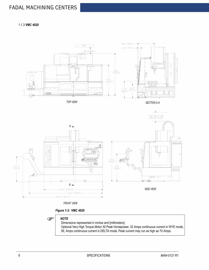
1.1.3 VMC 4020
6
Figure 1-3: VMC 4020
NOTE Dimensions represented in inches and [millimeters]. Optional Very High Torque Motor 30 Peak Horsepower, 32 Amps continuous current in WYE mode, 56, Amps continuous current in DELTA mode, Peak current may run as high as 70 Amps.
SPECIFICATIONS MAN-0121 R1
AUGUST 2005
FANUC MAINTENANCE MANUAL
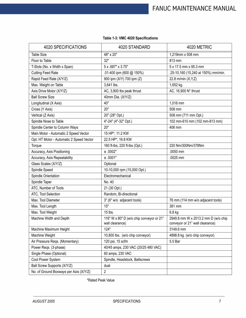
Table 1-3: VMC 4020 Specifications
4020 SPECIFICATIONS 4020 STANDARD 4020 METRICTable Size 48" x 20" 1,219mm x 508 mmFloor to Table 32" 813 mmT-Slots (No. x Width x Span) 5 x .687" x 3.75" 5 x 17.5 mm x 95.3 mmCutting Feed Rate .01-400 ipm (600 @ 150%) .25-10,160 (15,240 at 150%) mm/min. Rapid Feed Rate (X/Y/Z) 900 ipm (X/Y) 700 ipm (Z) 22.8 m/min (X,Y,Z)Max. Weight on Table 3,641 lbs. 1,652 kg.Axis Drive Motor (X/Y/Z) AC, 3,800 lbs peak thrust AC, 16,900 N* thrustBall Screw Size 40mm Dia. (X/Y/Z)Longitudinal (X Axis) 40" 1,016 mmCross (Y Axis) 20" 508 mmVertical (Z Axis) 20" (28" Opt.) 508 mm (711 mm Opt.)Spindle Nose to Table 4"-24" (4"-32" Opt.) 102 mm-610 mm (102 mm-813 mm)Spindle Center to Column Ways 20" 406 mmMain Motor - Automatic 2 Speed Vector 15 HP*, 11.2 KWOpt. HT Motor - Automatic 2 Speed Vector 22.5 HP*, 16.8 KWTorque 160 ft-lbs, 220 ft-lbs (Opt.) 220 Nm/300Nm/378NmAccuracy, Axis Positioning ± .0002" .0050 mmAccuracy, Axis Repeatability ± .0001" .0025 mmGlass Scales (X/Y/Z) OptionalSpindle Speed 10-10,000 rpm (15,000 Opt.)Spindle Orientation ElectromechanicalSpindle Taper No. 40ATC, Number of Tools 21 (30 Opt.)ATC, Tool Selection Random, Bi-directionalMax. Tool Diameter 3" (6" w/o adjacent tools) 76 mm (114 mm w/o adjacent tools)Max. Tool Length 15" 381 mmMax. Tool Weight 15 lbs. 6.8 kgMachine Width and Depth 116" W x 80" D (w/o chip conveyor or 21”
wall clearance)2949.8 mm W x 2013.2 mm D (w/o chip conveyor or 21” wall clearance)
Machine Maximum Height 124" 3149.6 mmMachine Weight 10,800 lbs. (w/o chip conveyor) 4898.8 kg (w/o chip conveyor)Air Pressure Reqs. (Momentary) 120 psi, 15 scfm 5.5 BarPower Reqs. (3-phase) 40/45 amps, 230 VAC (20/25 480 VAC)Single Phase (Optional) 60 amps, 230 VACCool Power System Spindle, Headstock, BallscrewsBall Screw Supports (X/Y/Z) dualNo. of Ground Boxways per Axis (X/Y/Z) 2
*Rated Peak Value
SPECIFICATIONS 7
FADAL MACHINING CENTERS
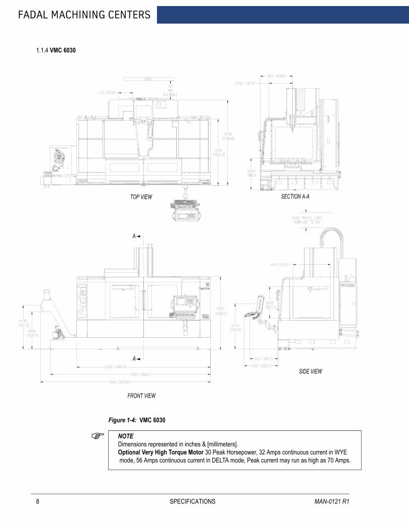
1.1.4 VMC 6030
8
Figure 1-4: VMC 6030
NOTE Dimensions represented in inches & [millimeters].Optional Very High Torque Motor 30 Peak Horsepower, 32 Amps continuous current in WYE mode, 56 Amps continuous current in DELTA mode, Peak current may run as high as 70 Amps.
SPECIFICATIONS MAN-0121 R1

AUGUST 2005
FANUC MAINTENANCE MANUAL
Table 1-4: VMC 6030 Specifications
6030 SPECIFICATIONS 6030 STANDARD 6030 METRICTable Size 62.5 x 30" 1,588mm x 762 mmFloor to Table 36" 914 mmT-Slots (No. x Width x Span) 5 x .687" x 5.5" 5 x 17.5 mm x 139.7 mmCutting Feed Rate .01-250 ipm (375 @ 150%) .25-6,350 (9,525 at 150%) mm/min. Rapid Feed Rate (X/Y/Z) 400 ipm (X/Y/Z) 10.1 m/min (X,Y,Z)Max. Weight on Table 4,120 lbs. 1,869 kg.Axis Drive Motor (X/Y/Z) AC, 5,000 lbs peak thrust AC, 22,420 N* thrustBall Screw Size 1.75" Dia. (X/Y) 1.50" Dia. (Z) 44.45 mm Dia (X,Y) 38.1 mm Dia. (Z)Longitudinal (X Axis) 60" 1,524 mmCross (Y Axis) 30" 762 mmVertical (Z Axis) 30" 762 mm Spindle Nose to Table 5.5"-35.5" 140 mm-902 mmSpindle Center to Column Ways 16" 406 mmMain Motor - Automatic 2 Speed Vector 15 HP*, 11.2 KWOpt. HT Motor - Automatic 2 Speed Vector 22.5 HP*, 16.8 KWTorque 160 ft.-lbs, 220 ft-lbs (Opt.) 300 Nm/375NmAccuracy, Axis Positioning ± .0004" .0076 mmAccuracy, Axis Repeatability ± .0002" .0038 mmGlass Scales (X/Y/Z) OptionalSpindle Speed 10-10,000 rpmSpindle Orientation ElectromechanicalSpindle Taper No. 40ATC, Number of Tools 21 (30 Opt.)ATC, Tool Selection Random, Bi-directionalMax. Tool Diameter 3" (4.5" w/o adjacent tools) 76 mm (114 mm w/o adjacent tools)Max. Tool Length 15" 381mmMax. Tool Weight 15 lbs. 6.8 kgMachine Width and Depth 158" W x 93" D (w/o chip conveyor and
21” wall clearance)4009.9 mm x 2366.8 mm D (w/o chip con-veyor and 21” wall clearance)
Machine Maximum Height 141" 3581.4 mm Machine Weight 17,300 lbs. (w/o chip conveyor) 7847.1 kg (w/o chip conveyor)Air Pressure Reqs. (Momentary) 120 psi, 15 scfm 5.5 BarPower Reqs. (3-phase) 40/45, 230 VAC (20/25, 480 VAC)Single Phase (Optional) 60 amps, 230 VACCool Power System Spindle, Headstock, Ballscrew (Y)Ball Screw Supports (X/Y/Z) dualNo. of Ground Boxways per Axis (X/Y/Z) 2
*Rated Peak Value
SPECIFICATIONS 9

FADAL MACHINING CENTERS
1.1.5 VMC 8030
10
Figure 1-5: VMC 8030
NOTE Dimensions represented in inches & [millimeters].Optional Very High Torque Motor 30 Peak Horsepower, 32 Amps continuous current in WYE mode, 56 Amps continuous current in DELTA mode, Peak current may run as high as 70 Amps.
SPECIFICATIONS MAN-0121 R1
AUGUST 2005
FANUC MAINTENANCE MANUAL
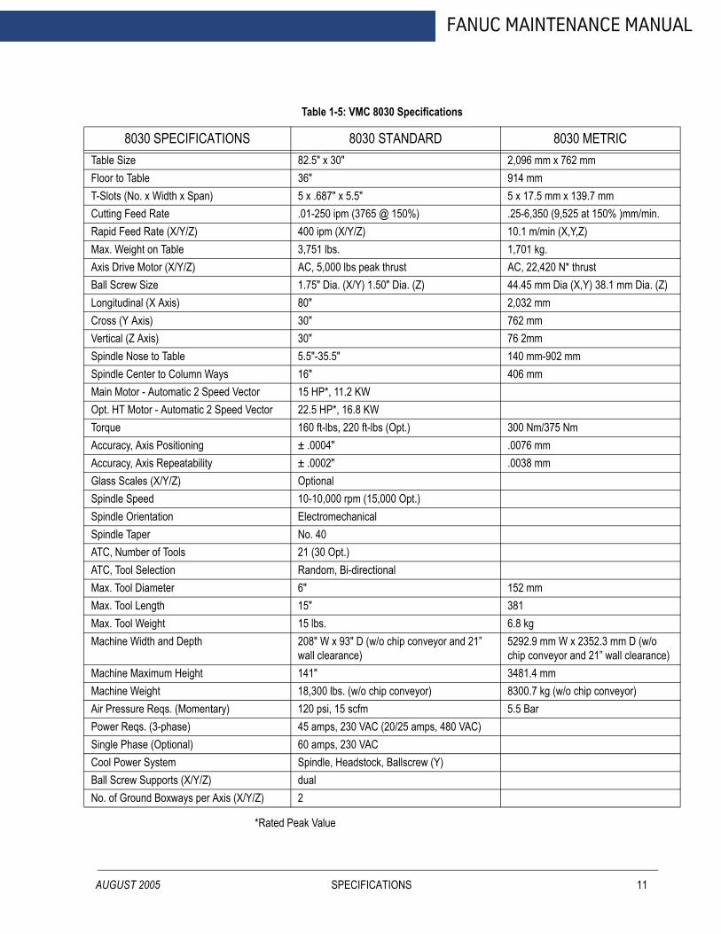
Table 1-5: VMC 8030 Specifications
8030 SPECIFICATIONS 8030 STANDARD 8030 METRICTable Size 82.5" x 30" 2,096 mm x 762 mmFloor to Table 36" 914 mmT-Slots (No. x Width x Span) 5 x .687" x 5.5" 5 x 17.5 mm x 139.7 mmCutting Feed Rate .01-250 ipm (3765 @ 150%) .25-6,350 (9,525 at 150% )mm/min. Rapid Feed Rate (X/Y/Z) 400 ipm (X/Y/Z) 10.1 m/min (X,Y,Z)Max. Weight on Table 3,751 lbs. 1,701 kg.Axis Drive Motor (X/Y/Z) AC, 5,000 lbs peak thrust AC, 22,420 N* thrustBall Screw Size 1.75" Dia. (X/Y) 1.50" Dia. (Z) 44.45 mm Dia (X,Y) 38.1 mm Dia. (Z)Longitudinal (X Axis) 80" 2,032 mmCross (Y Axis) 30" 762 mmVertical (Z Axis) 30" 76 2mm Spindle Nose to Table 5.5"-35.5" 140 mm-902 mmSpindle Center to Column Ways 16" 406 mmMain Motor - Automatic 2 Speed Vector 15 HP*, 11.2 KWOpt. HT Motor - Automatic 2 Speed Vector 22.5 HP*, 16.8 KWTorque 160 ft-lbs, 220 ft-lbs (Opt.) 300 Nm/375 NmAccuracy, Axis Positioning ± .0004" .0076 mmAccuracy, Axis Repeatability ± .0002" .0038 mmGlass Scales (X/Y/Z) OptionalSpindle Speed 10-10,000 rpm (15,000 Opt.)Spindle Orientation ElectromechanicalSpindle Taper No. 40ATC, Number of Tools 21 (30 Opt.)ATC, Tool Selection Random, Bi-directionalMax. Tool Diameter 6" 152 mm Max. Tool Length 15" 381Max. Tool Weight 15 lbs. 6.8 kgMachine Width and Depth 208" W x 93" D (w/o chip conveyor and 21”
wall clearance)5292.9 mm W x 2352.3 mm D (w/o chip conveyor and 21” wall clearance)
Machine Maximum Height 141" 3481.4 mm Machine Weight 18,300 lbs. (w/o chip conveyor) 8300.7 kg (w/o chip conveyor)Air Pressure Reqs. (Momentary) 120 psi, 15 scfm 5.5 BarPower Reqs. (3-phase) 45 amps, 230 VAC (20/25 amps, 480 VAC) Single Phase (Optional) 60 amps, 230 VACCool Power System Spindle, Headstock, Ballscrew (Y)Ball Screw Supports (X/Y/Z) dualNo. of Ground Boxways per Axis (X/Y/Z) 2
*Rated Peak Value
SPECIFICATIONS 11
FADAL MACHINING CENTERS
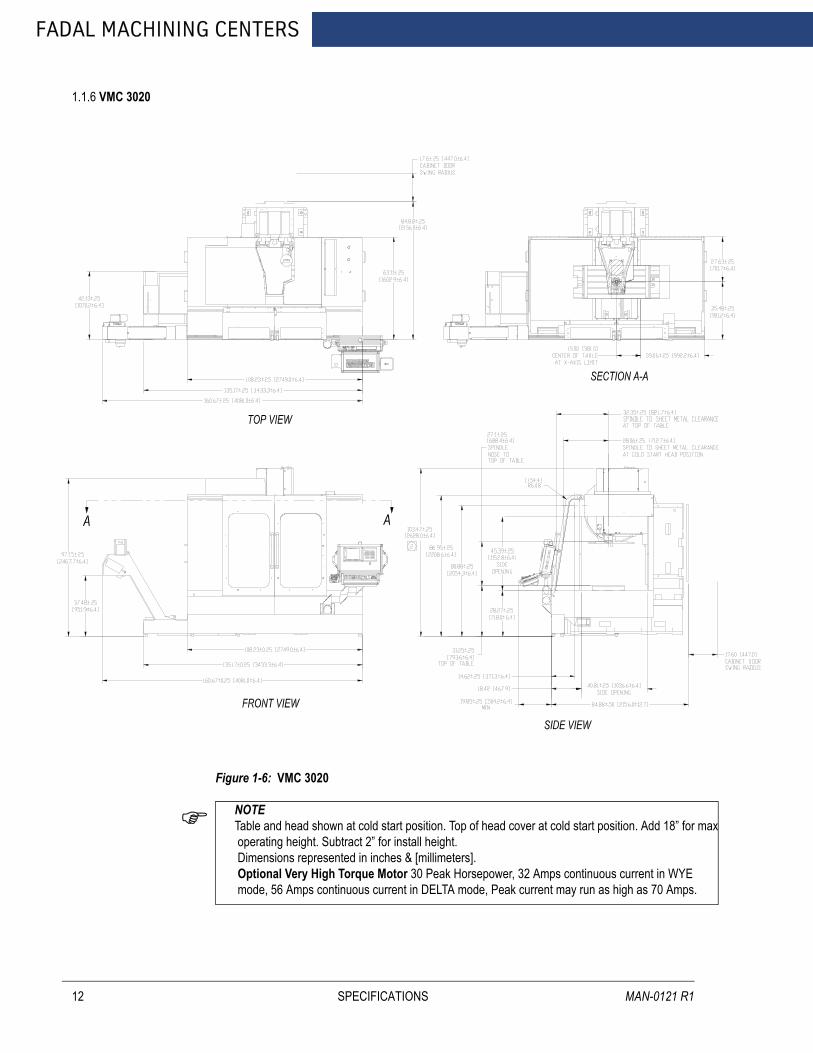
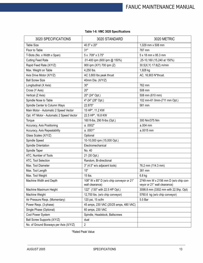
1.1.6 VMC 3020
12
Figure 1-6: VMC 3020
NOTE Table and head shown at cold start position. Top of head cover at cold start position. Add 18” for max operating height. Subtract 2” for install height. Dimensions represented in inches & [millimeters]. Optional Very High Torque Motor 30 Peak Horsepower, 32 Amps continuous current in WYE mode, 56 Amps continuous current in DELTA mode, Peak current may run as high as 70 Amps.
SPECIFICATIONS MAN-0121 R1
AUGUST 2005
FANUC MAINTENANCE MANUAL
Table 1-6: VMC 3020 Specifications
3020 SPECIFICATIONS 3020 STANDARD 3020 METRICTable Size 40.5" x 20" 1,029 mm x 508 mmFloor to Table 31" 787 mmT-Slots (No. x Width x Span) 5 x .709" x 3.75" 5 x 18 mm x 95.3 mmCutting Feed Rate .01-400 ipm (600 ipm @ 150%) .25-10,160 (15,240 at 150%)Rapid Feed Rate (X/Y/Z) 900 ipm (X/Y) 700 ipm (Z) 30.5(X,Y) 17.8(Z) m/minMax. Weight on Table 4,250 lbs. 1,928 kgAxis Drive Motor (X/Y/Z) AC 3,800 lbs peak thrust AC, 16,903 N*thrust.Ball Screw Size 40mm Dia. (X/Y/Z)Longitudinal (X Axis) 30" 762 mmCross (Y Axis) 20" 508 mmVertical (Z Axis) 20" (24" Opt.) 508 mm (610 mm) Spindle Nose to Table 4"-24" (28" Opt.) 102 mm-61 0mm-(711 mm Opt.)Spindle Center to Column Ways 22.875" 581 mmMain Motor - Automatic 2 Speed Vector 15 HP*, 11.2 KWOpt. HT Motor - Automatic 2 Speed Vector 22.5 HP*, 16.8 KWTorque 160 ft-lbs, 290 ft-lbs (Opt.) 300 Nm/375 NmAccuracy, Axis Positioning ± .0002" ±.004 mmAccuracy, Axis Repeatability ± .0001" ±.0015 mmGlass Scales (X/Y/Z) OptionalSpindle Speed 10-10,000 rpm (15,000 Opt.)Spindle Orientation ElectromechanicalSpindle Taper No. 40ATC, Number of Tools 21 (30 Opt.)ATC, Tool Selection Random, Bi-directionalMax. Tool Diameter 3" (4.5" w/o adjacent tools) 76.2 mm (114.3 mm)Max. Tool Length 15" 381 mmMax. Tool Weight 15 lbs. 6.8 kgMachine Width and Depth 108" W x 85" D (w/o chip conveyor or 21”
wall clearance)2749 mm W x 2156 mm D (w/o chip con-veyor or 21” wall clearance)
Machine Maximum Height 122" (130" with 22.5 HP Opt.) 3098.8 mm (3302 mm with 22.5hp. Opt) Machine Weight 12,700 lbs. (w/o chip conveyor) 5760.6 kg (w/o chip conveyor)Air Pressure Reqs. (Momentary) 120 psi, 15 scfm 5.5 BarPower Reqs. (3-phase) 45 amps, 230 VAC (20/25 amps, 480 VAC)Single Phase (Optional) 60 amps, 230 VACCool Power System Spindle, Headstock, BallscrewsBall Screw Supports (X/Y/Z) dualNo. of Ground Boxways per Axis (X/Y/Z) 2
*Rated Peak Value
SPECIFICATIONS 13
FADAL MACHINING CENTERS
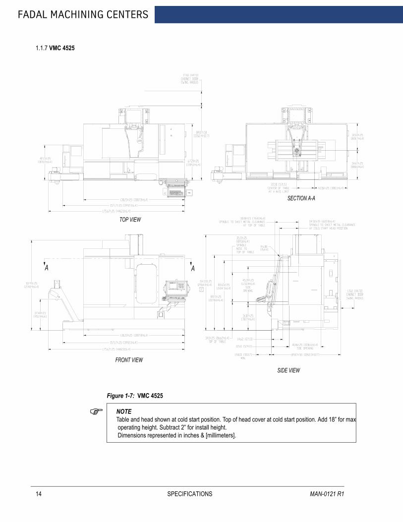
1.1.7 VMC 4525
14
Figure 1-7: VMC 4525
NOTE Table and head shown at cold start position. Top of head cover at cold start position. Add 18” for max operating height. Subtract 2” for install height. Dimensions represented in inches & [millimeters].
SPECIFICATIONS MAN-0121 R1

AUGUST 2005
FANUC MAINTENANCE MANUAL
Table 1-7: VMC 4525 Specifications
4525 SPECIFICATIONS 4525 STANDARD 4525 METRICTable Size 53.5" x 25" 1,359mm x 635mmFloor to Table 31" 787mmT-Slots (No. x Width x Span) 5 x .709" x 4.92" 5 x 18mm x 125mmCutting Feed Rate .01-400 ipm (600 ipm @ 150%) .25-10,160 (15,240 at 150%)Rapid Feed Rate (X/Y/Z) 900 ipm (X/Y) 700 ipm (Z) 30.5(X,Y) 17.8(Z) m/minMax. Weight on Table 4,250 lbs. 1,928 kg.Axis Drive Motor (X/Y/Z) AC 3,800 lbs peak thrust AC, 16,903 N*thrust.Ball Screw Size 40mm Dia. (X/Y/Z)Longitudinal (X Axis) 45" 1,143 mmCross (Y Axis) 25" 635mmVertical (Z Axis) 24" 610 Spindle Nose to Table 4"-24" 102mm-610mmSpindle Center to Column Ways 27.87" 708mmMain Motor - Automatic 2 Speed Vector 22.5 HP*, 16.8 KWOpt. HT Motor - Automatic 2 Speed Vector 30 HP*, 22.4 KWTorque 220 ft-lbs, 270 ft-lbs (Opt.) 300 Nm/375NmAccuracy, Axis Positioning ± .00016" ±.004mmAccuracy, Axis Repeatability ± .00006" ±.0015mmGlass Scales (X/Y/Z) OptionalSpindle Speed 10-10,000 rpm (15,000 Opt.)Spindle Orientation ElectromechanicalSpindle Taper No. 40ATC, Number of Tools 1.9 sec dual arm / 24 toolsATC, Tool Selection Random, Bi-directionalMax. Tool Diameter 4" (4.5" w/o adjacent tools) 101.6mm (114.3mm)Max. Tool Length 15" 381mmMax. Tool Weight 15 lbs. 6.8 kgMachine Width and Depth 131" W x 90" D (w/o chip conveyor or 21”
wall clearance)3307.8 mm W x 2262.4 mm D (w/o chip conveyor or 21” wall clearance)
Machine Maximum Height 133" 3378.2 mmMachine Weight 13,900 lbs. (w/o chip conveyor) 6304.9 kg (w/o chip conveyor)Air Pressure Reqs. (Momentary) 120 psi, 15 scfm 5.5 BarPower Reqs. (3-phase) 40/60 amps, 230 VAC (20/25 amps, 480 VAC)Single Phase (Optional) 60 amps, 230 VACCool Power System Spindle, Headstock, BallscrewsBall Screw Supports (X/Y/Z) dualNo. of Ground Boxways per Axis (X/Y/Z) 2
*Rated Peak Value
SPECIFICATIONS 15

FADAL MACHINING CENTERS
1.1.8 VMC 6535
16
Figure 1-8: VMC 6535
SIDE VIEW FRONT VIEW
TOP VIEW - BASESCALE 2:1
TOP VIEW
NOTE Dimensions represented in inches & [millimeters].
SPECIFICATIONS
MAN-0121 R1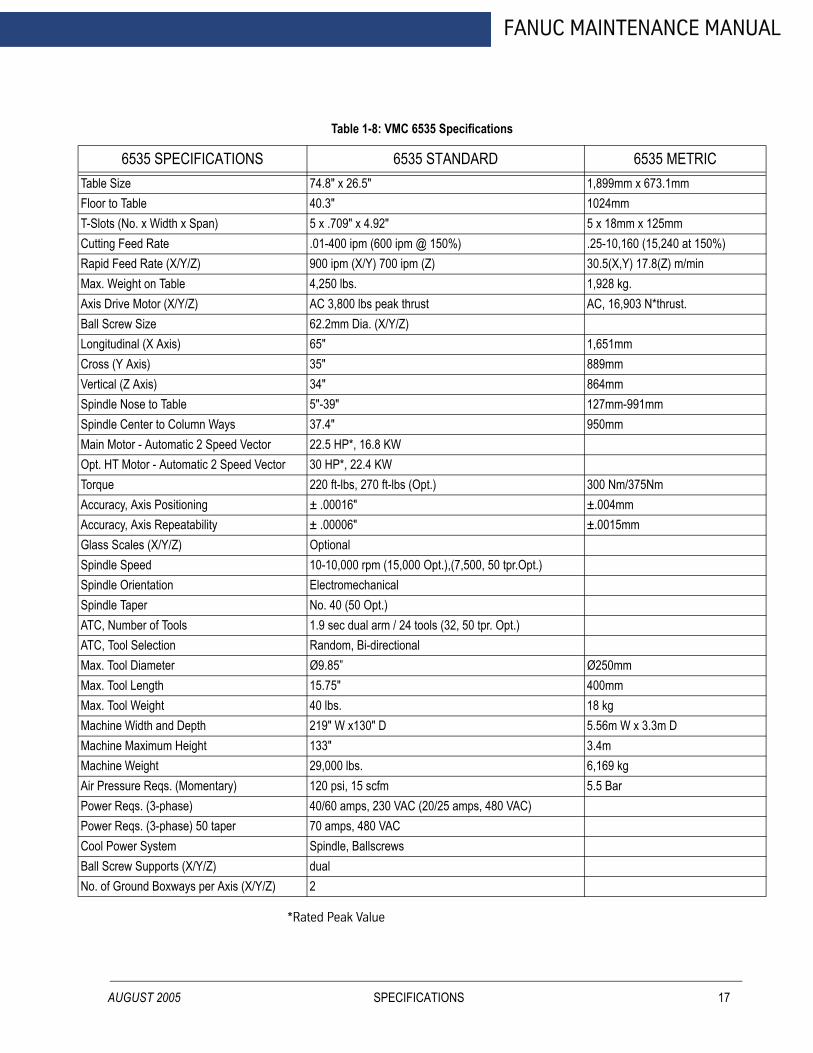
AUGUST 2005
FANUC MAINTENANCE MANUAL
TFTCRMABLCVSSMOTAAGSSSAAMMMMMMAPPCBN
Table 1-8: VMC 6535 Specifications
6535 SPECIFICATIONS 6535 STANDARD 6535 METRICable Size 74.8" x 26.5" 1,899mm x 673.1mmloor to Table 40.3" 1024mm-Slots (No. x Width x Span) 5 x .709" x 4.92" 5 x 18mm x 125mmutting Feed Rate .01-400 ipm (600 ipm @ 150%) .25-10,160 (15,240 at 150%)apid Feed Rate (X/Y/Z) 900 ipm (X/Y) 700 ipm (Z) 30.5(X,Y) 17.8(Z) m/minax. Weight on Table 4,250 lbs. 1,928 kg.xis Drive Motor (X/Y/Z) AC 3,800 lbs peak thrust AC, 16,903 N*thrust.all Screw Size 62.2mm Dia. (X/Y/Z)ongitudinal (X Axis) 65" 1,651mmross (Y Axis) 35" 889mmertical (Z Axis) 34" 864mm pindle Nose to Table 5"-39" 127mm-991mmpindle Center to Column Ways 37.4" 950mmain Motor - Automatic 2 Speed Vector 22.5 HP*, 16.8 KWpt. HT Motor - Automatic 2 Speed Vector 30 HP*, 22.4 KWorque 220 ft-lbs, 270 ft-lbs (Opt.) 300 Nm/375Nmccuracy, Axis Positioning ± .00016" ±.004mmccuracy, Axis Repeatability ± .00006" ±.0015mmlass Scales (X/Y/Z) Optionalpindle Speed 10-10,000 rpm (15,000 Opt.),(7,500, 50 tpr.Opt.)pindle Orientation Electromechanicalpindle Taper No. 40 (50 Opt.)TC, Number of Tools 1.9 sec dual arm / 24 tools (32, 50 tpr. Opt.)TC, Tool Selection Random, Bi-directionalax. Tool Diameter Ø9.85” Ø250mmax. Tool Length 15.75" 400mmax. Tool Weight 40 lbs. 18 kgachine Width and Depth 219" W x130" D 5.56m W x 3.3m Dachine Maximum Height 133" 3.4machine Weight 29,000 lbs. 6,169 kgir Pressure Reqs. (Momentary) 120 psi, 15 scfm 5.5 Barower Reqs. (3-phase) 40/60 amps, 230 VAC (20/25 amps, 480 VAC)ower Reqs. (3-phase) 50 taper 70 amps, 480 VAC ool Power System Spindle, Ballscrewsall Screw Supports (X/Y/Z) dualo. of Ground Boxways per Axis (X/Y/Z) 2
*Rated Peak Value
SPECIFICATIONS 17
FADAL MACHINING CENTERS
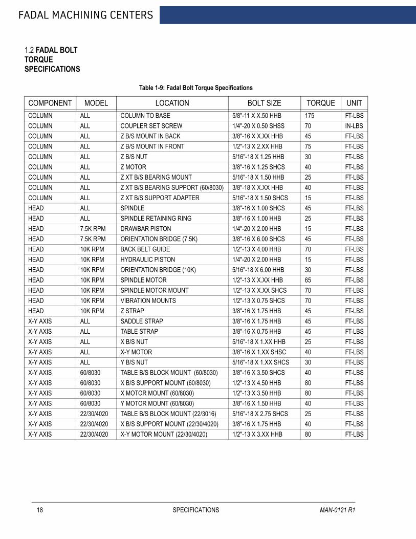
1.2 FADAL BOLT TORQUE SPECIFICATIONS
18
Table 1-9: Fadal Bolt Torque Specifications
COMPONENT MODEL LOCATION BOLT SIZE TORQUE UNITCOLUMN ALL COLUMN TO BASE 5/8"-11 X X.50 HHB 175 FT-LBSCOLUMN ALL COUPLER SET SCREW 1/4"-20 X 0.50 SHSS 70 IN-LBSCOLUMN ALL Z B/S MOUNT IN BACK 3/8"-16 X X.XX HHB 45 FT-LBSCOLUMN ALL Z B/S MOUNT IN FRONT 1/2"-13 X 2.XX HHB 75 FT-LBSCOLUMN ALL Z B/S NUT 5/16"-18 X 1.25 HHB 30 FT-LBSCOLUMN ALL Z MOTOR 3/8"-16 X 1.25 SHCS 40 FT-LBSCOLUMN ALL Z XT B/S BEARING MOUNT 5/16"-18 X 1.50 HHB 25 FT-LBSCOLUMN ALL Z XT B/S BEARING SUPPORT (60/8030) 3/8"-18 X X.XX HHB 40 FT-LBSCOLUMN ALL Z XT B/S SUPPORT ADAPTER 5/16"-18 X 1.50 SHCS 15 FT-LBSHEAD ALL SPINDLE 3/8"-16 X 1.00 SHCS 45 FT-LBSHEAD ALL SPINDLE RETAINING RING 3/8"-16 X 1.00 HHB 25 FT-LBSHEAD 7.5K RPM DRAWBAR PISTON 1/4"-20 X 2.00 HHB 15 FT-LBSHEAD 7.5K RPM ORIENTATION BRIDGE (7.5K) 3/8"-16 X 6.00 SHCS 45 FT-LBSHEAD 10K RPM BACK BELT GUIDE 1/2"-13 X 4.00 HHB 70 FT-LBSHEAD 10K RPM HYDRAULIC PISTON 1/4"-20 X 2.00 HHB 15 FT-LBSHEAD 10K RPM ORIENTATION BRIDGE (10K) 5/16"-18 X 6.00 HHB 30 FT-LBSHEAD 10K RPM SPINDLE MOTOR 1/2"-13 X X.XX HHB 65 FT-LBSHEAD 10K RPM SPINDLE MOTOR MOUNT 1/2"-13 X X.XX SHCS 70 FT-LBSHEAD 10K RPM VIBRATION MOUNTS 1/2"-13 X 0.75 SHCS 70 FT-LBSHEAD 10K RPM Z STRAP 3/8"-16 X 1.75 HHB 45 FT-LBSX-Y AXIS ALL SADDLE STRAP 3/8"-16 X 1.75 HHB 45 FT-LBSX-Y AXIS ALL TABLE STRAP 3/8"-16 X 0.75 HHB 45 FT-LBSX-Y AXIS ALL X B/S NUT 5/16"-18 X 1.XX HHB 25 FT-LBSX-Y AXIS ALL X-Y MOTOR 3/8"-16 X 1.XX SHSC 40 FT-LBSX-Y AXIS ALL Y B/S NUT 5/16"-18 X 1.XX SHCS 30 FT-LBSX-Y AXIS 60/8030 TABLE B/S BLOCK MOUNT (60/8030) 3/8"-16 X 3.50 SHCS 40 FT-LBSX-Y AXIS 60/8030 X B/S SUPPORT MOUNT (60/8030) 1/2"-13 X 4.50 HHB 80 FT-LBSX-Y AXIS 60/8030 X MOTOR MOUNT (60/8030) 1/2"-13 X 3.50 HHB 80 FT-LBSX-Y AXIS 60/8030 Y MOTOR MOUNT (60/8030) 3/8"-16 X 1.50 HHB 40 FT-LBSX-Y AXIS 22/30/4020 TABLE B/S BLOCK MOUNT (22/3016) 5/16"-18 X 2.75 SHCS 25 FT-LBSX-Y AXIS 22/30/4020 X B/S SUPPORT MOUNT (22/30/4020) 3/8"-16 X 1.75 HHB 40 FT-LBSX-Y AXIS 22/30/4020 X-Y MOTOR MOUNT (22/30/4020) 1/2"-13 X 3.XX HHB 80 FT-LBS
SPECIFICATIONS MAN-0121 R1
FANUC MAINTENANCE MANUAL
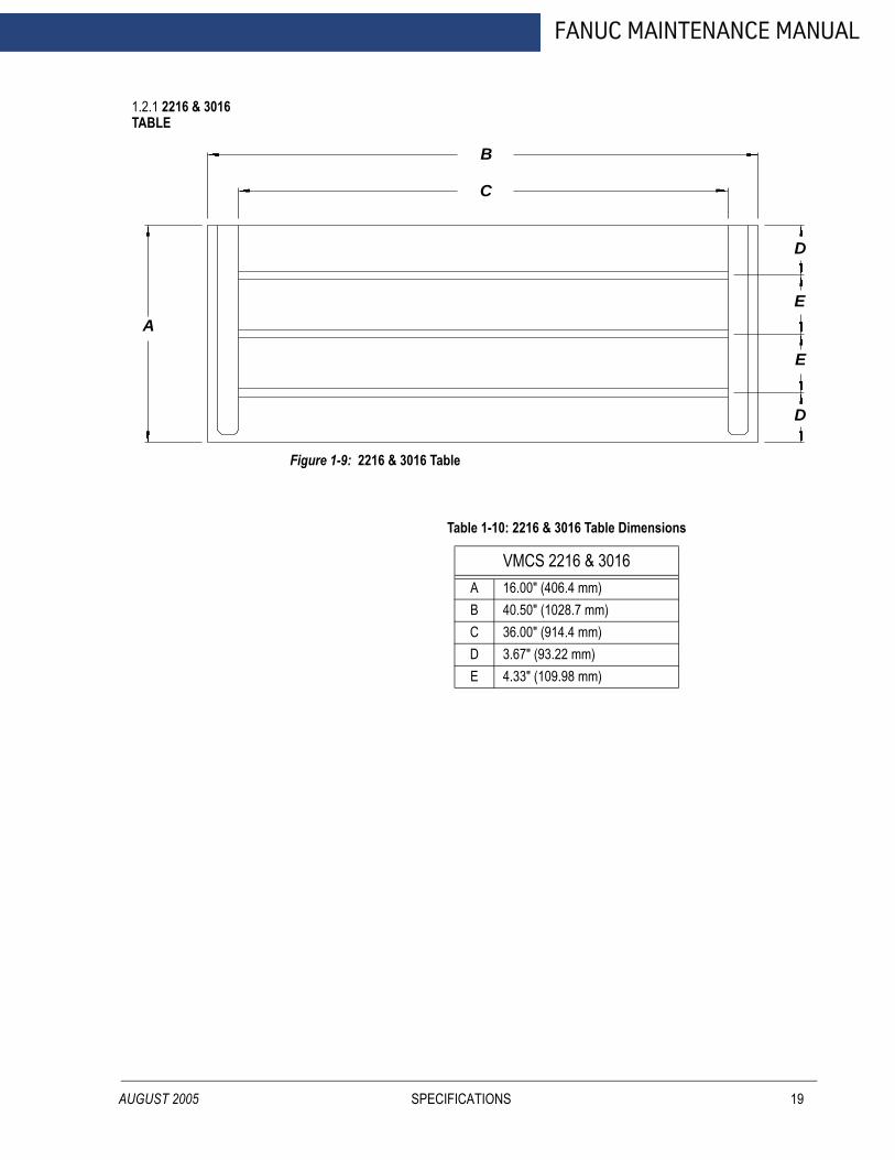
1.2.1 2216 & 3016 TABLE
AUGUST 2005
Figure 1-9: 2216 & 3016 Table
A
B
C
D
D
E
E
Table 1-10: 2216 & 3016 Table Dimensions
VMCS 2216 & 3016A 16.00" (406.4 mm)B 40.50" (1028.7 mm)C 36.00" (914.4 mm)D 3.67" (93.22 mm)E 4.33" (109.98 mm)
SPECIFICATIONS 19

FADAL MACHINING CENTERS
1.2.2 3020 & 4525 TABLE
20
Figure 1-10: 3020 & 4525 Table
A
B
C
D
E
E
E
E
F
Table 1-11: 3020 & 4525 Table Dimensions
VMC 3020 VMC 4525A 20.00” (508 mm) A 25.00” (635 mm)B 41.75” (1060.45 mm) B 54.76” (1390.90 mm)C 36.00” (914.40 mm) C 49.00” (1244.60 mm)D 2.874” (730 mm) D 3.0125” (76.51 mm)E 3.74” (95 mm) E 4.921” (124.99 mm)F 2.1655” (55 mm) F 2.3035” (58.51 mm)
SPECIFICATIONS MAN-0121 R1

FANUC MAINTENANCE MANUAL
1.2.3 4020 TABLE
AUGUST 2005
Figure 1-11: 4020 Table
A
B
C
D
D
E
E
E
E
Table 1-12: 4020 Table Dimensions
VMC 4020A 20.00” (508 mm)B 49.00” (1244.66 mm)C 43.50” (1104.9 mm)D 2.52” (64 mm)E 3.740” (95 mm)
SPECIFICATIONS 21

FADAL MACHINING CENTERS
1.2.4 6030 TABLE
22
Figure 1-12: 6030 TABLE
A
B
C
D
D
E
E
E
E
Table 1-13: 6030 Table Dimensions
VMC 6030A 30.00” (762 mm)B 63.50” (1612.9 mm)C 58.00” (1473.2 mm)D 3.976” (101 mm)E 5.512” (140 mm)
SPECIFICATIONS MAN-0121 R1
FANUC MAINTENANCE MANUAL
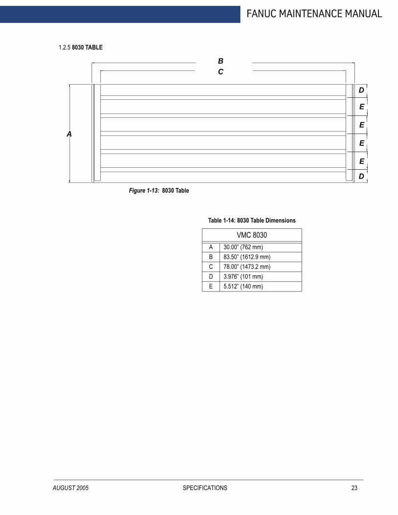
1.2.5 8030 TABLE
AUGUST 2005
Figure 1-13: 8030 Table
A
BC
D
E
E
E
E
D
Table 1-14: 8030 Table Dimensions
VMC 8030A 30.00” (762 mm)B 83.50” (1612.9 mm)C 78.00” (1473.2 mm)D 3.976” (101 mm)E 5.512” (140 mm)
SPECIFICATIONS 23
FADAL MACHINING CENTERS
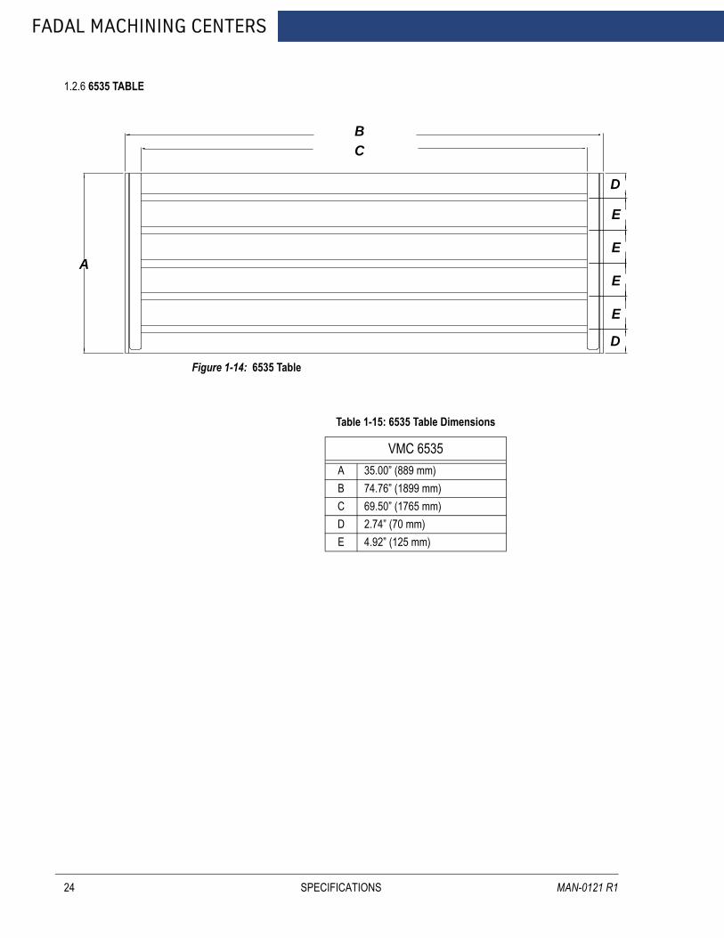
1.2.6 6535 TABLE
24
Figure 1-14: 6535 Table
A
BC
D
E
E
E
E
D
Table 1-15: 6535 Table Dimensions
VMC 6535A 35.00” (889 mm)B 74.76” (1899 mm)C 69.50” (1765 mm)D 2.74” (70 mm)E 4.92” (125 mm)
SPECIFICATIONS MAN-0121 R1
FANUC MAINTENANCE MANUAL
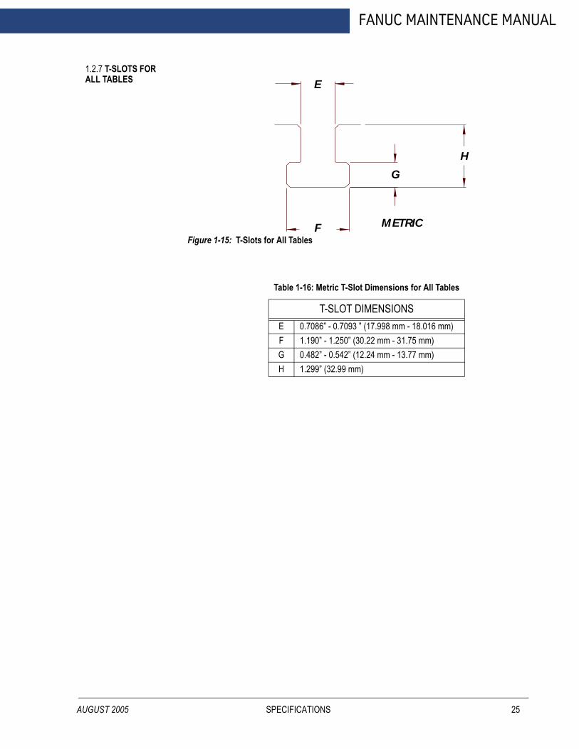
1.2.7 T-SLOTS FOR ALL TABLES
AUGUST 2005
Figure 1-15: T-Slots for All Tables
Table 1-16: Metric T-Slot Dimensions for All Tables
T-SLOT DIMENSIONSE 0.7086” - 0.7093 ” (17.998 mm - 18.016 mm)F 1.190” - 1.250” (30.22 mm - 31.75 mm)G 0.482” - 0.542” (12.24 mm - 13.77 mm)H 1.299” (32.99 mm)
E
F
G
H
METRIC
SPECIFICATIONS 25
FADAL MACHINING CENTERS
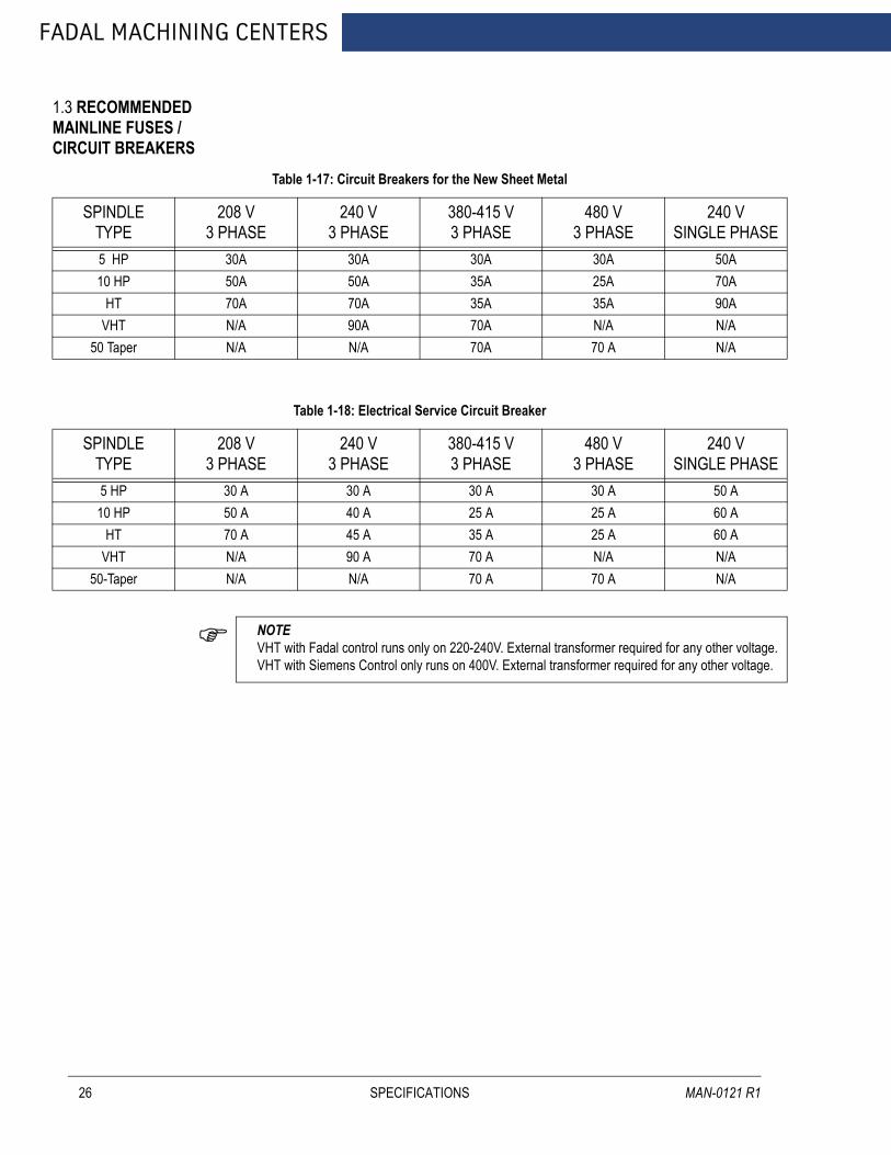
1.3 RECOMMENDED MAINLINE FUSES / CIRCUIT BREAKERS
26
Table 1-17: Circuit Breakers for the New Sheet Metal
SPINDLETYPE
208 V3 PHASE
240 V3 PHASE
380-415 V3 PHASE
480 V3 PHASE
240 VSINGLE PHASE
5 HP 30A 30A 30A 30A 50A10 HP 50A 50A 35A 25A 70A
HT 70A 70A 35A 35A 90AVHT N/A 90A 70A N/A N/A
50 Taper N/A N/A 70A 70 A N/A
Table 1-18: Electrical Service Circuit Breaker
SPINDLETYPE
208 V3 PHASE
240 V3 PHASE
380-415 V3 PHASE
480 V3 PHASE
240 VSINGLE PHASE
5 HP 30 A 30 A 30 A 30 A 50 A10 HP 50 A 40 A 25 A 25 A 60 A
HT 70 A 45 A 35 A 25 A 60 AVHT N/A 90 A 70 A N/A N/A
50-Taper N/A N/A 70 A 70 A N/A
NOTE VHT with Fadal control runs only on 220-240V. External transformer required for any other voltage.VHT with Siemens Control only runs on 400V. External transformer required for any other voltage.
SPECIFICATIONS MAN-0121 R1

FANUC MAINTENANCE MANUAL
AUGUST 2005
2.0 PRE-INSTALLATION PROCEDURES
PRE-INSTALLATION PROCEDURES 27

FADAL MACHINING CENTERS
2.1 FOUNDATION
28
WARNING!The VMC MUST be placed on a surface that will support the combined weight of the VMC, options, fixtures, and tooling, etc. (refer to the VMC Specifications section at the beginning of this manual for VMC weights).
1. It is recommended that most models be placed on a isolated concrete pad 8-12” thick. For VMC 6030 and larger the foundation pad should be 12-15”. (Figure 2-1:, Dimension C). For A and B dimensions, see Table 2-1:Isolation Pad Dimensions.
Figure 2-1: Typical Pad Construction
2. The VMC should be positioned on a single slab. Placing the VMC over an expansion joint may cause the VMC to shift when each individual slab moves.
3. The surface below the leveling pads should be free from cracks. Placing the VMC over a crack may cause the VMC to shift during use. Inadequate flooring could result in mechanical degradation.
4. Bolt the VMC directly to the pad through the .953” diameter holes that are provided in the base casting. The dimensions for the base mounting holes of all machines are in the VMC Specifications section (See Specifications, Section 1.0, MAN-0121R1). Anchors are to be installed as shown below (Figure 2-2: Anchor Stud
5/8 FELT
5/8 FELT
#4 REBARAS SHOWN
CAULK SEAMS TOSEAL FLOOR TYP.
C
AB
PRE-INSTALLATION PROCEDURES MAN-0121 R1
AUGUST 2005
FANUC MAINTENANCE MANUAL
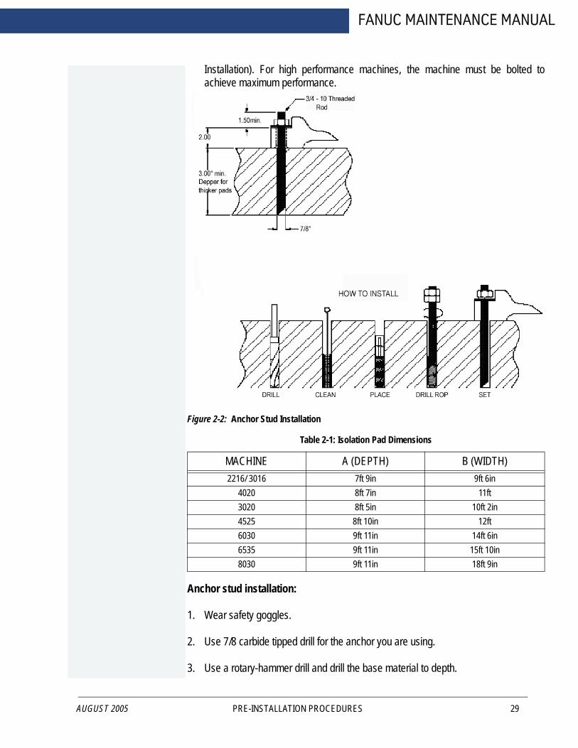
Installation). For high performance machines, the machine must be bolted to achieve maximum performance.
Figure 2-2: Anchor Stud Installation
Anchor stud installation:
1. Wear safety goggles.
2. Use 7/8 carbide tipped drill for the anchor you are using.
3. Use a rotary-hammer drill and drill the base material to depth.
Table 2-1: Isolation Pad Dimensions
MACHINE A (DEPTH) B (WIDTH)2216/ 3016 7ft 9in 9ft 6in
4020 8ft 7in 11ft3020 8ft 5in 10ft 2in4525 8ft 10in 12ft6030 9ft 11in 14ft 6in6535 9ft 11in 15ft 10in8030 9ft 11in 18ft 9in
PRE-INSTALLATION PROCEDURES 29

FADAL MACHINING CENTERS
30
4. Use proper eye and hearing protection while performing this step. Remove dust and rubble from the hole with compressed air and brush.
5. Insert capsule in the hole, either end first.
6. Select proper 1/2” SQ. drive socket and attach to sup-r-setter.
7. Jam nut on stud as per illustration.
8. Using a 1 1/8” socket insert the stud into the hole to break the capsule.
9. Under rotary power, push the stud to full depth, maintaining power for two or three seconds after the stud bottoms.
10. Promptly and carefully release the installation tool from the stud, leaving it undisturbed right through the prescribed curing time consistent with on-site temperature.
11. Install machine.
12. Level machine.
13. Add two flat washers, one lock washer and one nut per threaded rod.
14. Tighten nut, stop when washer gets flat, do not overtighten.
15. Recheck level.
Recommended curing time
58ºF to 68ºF 30 MIN50ºF to 58ºF 1 HR41ºF to 50ºF 2 HRs32ºF to 41ºF 4 HRs23ºF to 32ºF 8 HRs14ºF to 23ºF 24 HRs
Ground should be compacted to 90%. A layer of 3/4” (1”nominal) crushed rock can be applied at 6” thickness for added support.
For rebar in all pads, use #4 rebar 18” on center, three inches off the ground.
For vibration dampening, 5/8 or thicker felt on all sides is sufficient. If the customer wants to have a larger pad to support several machines, the pads should be 10-12” or
PRE-INSTALLATION PROCEDURES MAN-0121 R1

AUGUST 2005
FANUC MAINTENANCE MANUAL
thicker with # 4 rebar 18” on center three inches off the ground.
For stress lines in the concrete make sure they are such that they do not go under any of the machines. (If they do, this will eventually defeat the purpose of the pad.)
The top of the felt, if used, should be sealed with a caulking compound to prevent oils and coolants from penetrating the ground. (Compound must be resistant to oils and coolants of course). A recommended product is Volcum.
Concrete to use for the pad should be rated at least 3000 psi. It should also contain 3/4” (1” nominal) crushed rock. Curing time should be at least 7 days. The longer foundation is allowed to cure, the better. If accelerants are used to cure the concrete in less time, cracking is more likely to occur.
PRE-INSTALLATION PROCEDURES 31
FADAL MACHINING CENTERS
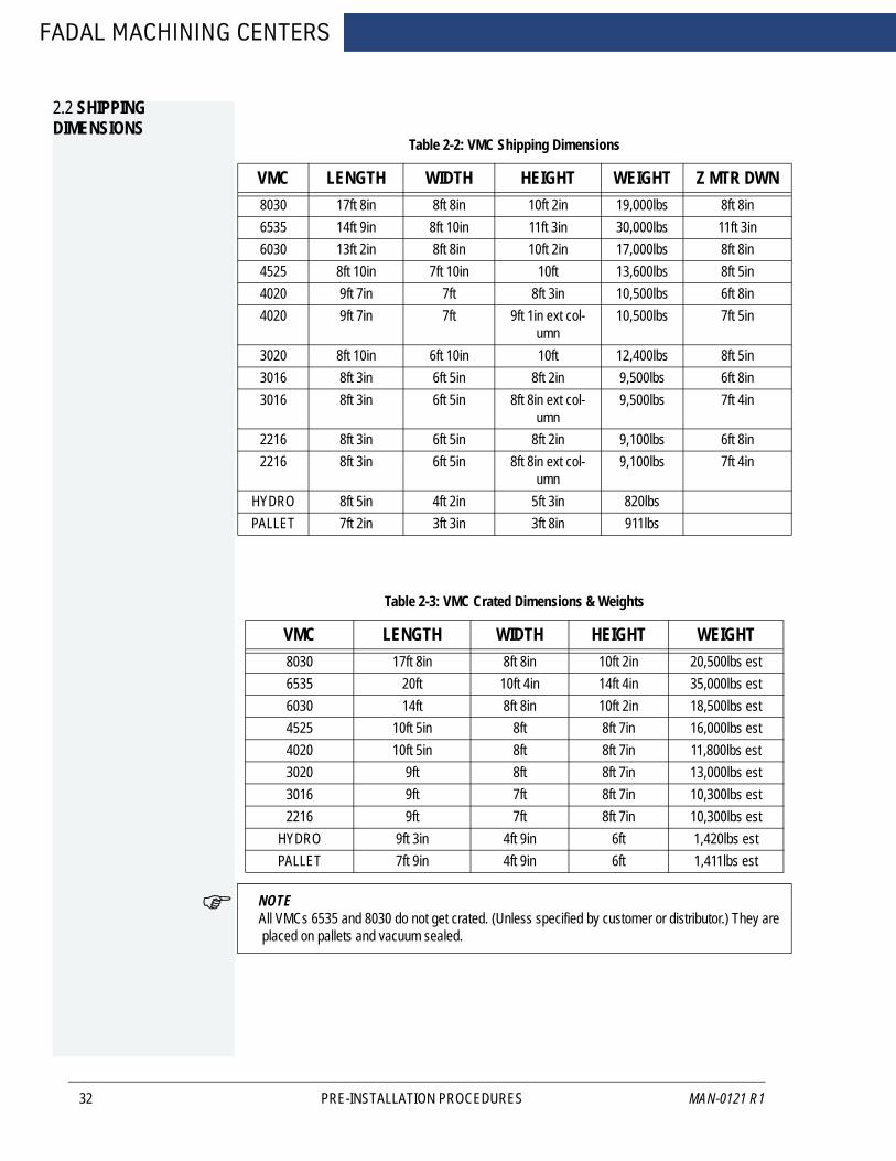
2.2 SHIPPING DIMENSIONS
32
NOTE All VMCs 6535 and 8030 do not get crated. (Unless specified by customer or distributor.) They are placed on pallets and vacuum sealed.
Table 2-2: VMC Shipping Dimensions
VMC LENGTH WIDTH HEIGHT WEIGHT Z MTR DWN8030 17ft 8in 8ft 8in 10ft 2in 19,000lbs 8ft 8in6535 14ft 9in 8ft 10in 11ft 3in 30,000lbs 11ft 3in6030 13ft 2in 8ft 8in 10ft 2in 17,000lbs 8ft 8in4525 8ft 10in 7ft 10in 10ft 13,600lbs 8ft 5in4020 9ft 7in 7ft 8ft 3in 10,500lbs 6ft 8in4020 9ft 7in 7ft 9ft 1in ext col-
umn10,500lbs 7ft 5in
3020 8ft 10in 6ft 10in 10ft 12,400lbs 8ft 5in3016 8ft 3in 6ft 5in 8ft 2in 9,500lbs 6ft 8in3016 8ft 3in 6ft 5in 8ft 8in ext col-
umn9,500lbs 7ft 4in
2216 8ft 3in 6ft 5in 8ft 2in 9,100lbs 6ft 8in2216 8ft 3in 6ft 5in 8ft 8in ext col-
umn9,100lbs 7ft 4in
HYDRO 8ft 5in 4ft 2in 5ft 3in 820lbsPALLET 7ft 2in 3ft 3in 3ft 8in 911lbs
Table 2-3: VMC Crated Dimensions & Weights
VMC LENGTH WIDTH HEIGHT WEIGHT8030 17ft 8in 8ft 8in 10ft 2in 20,500lbs est6535 20ft 10ft 4in 14ft 4in 35,000lbs est6030 14ft 8ft 8in 10ft 2in 18,500lbs est4525 10ft 5in 8ft 8ft 7in 16,000lbs est4020 10ft 5in 8ft 8ft 7in 11,800lbs est3020 9ft 8ft 8ft 7in 13,000lbs est3016 9ft 7ft 8ft 7in 10,300lbs est2216 9ft 7ft 8ft 7in 10,300lbs est
HYDRO 9ft 3in 4ft 9in 6ft 1,420lbs estPALLET 7ft 9in 4ft 9in 6ft 1,411lbs est
PRE-INSTALLATION PROCEDURES MAN-0121 R1

FANUC MAINTENANCE MANUAL
2.3 POSITIONING
AUGUST 2005
1. Place the VMC so that skylights or air vents are NOT directly overhead. Do not expose the machine to direct sunlight, or any other heat source. Do not place the machine in an area that will expose the machine to moisture, standing water, liquid or rain.
2. Ensure there is adequate room behind the VMC to fully open the rear cabinet door. Minimum clearance behind the machine is two feet (24”/ 60.96 cm.)
Figure 2-3: 24” Minimum Clearance Behind VMC
3. Ensure adequate ceiling clearance for the Z axis conduit with the Z axis in the Z+4.0” (10.16cm) position. VMCs with the Extended Travel option require an additional 8.0” (20.32cm) vertical clearance.
Table 2-4: Minimum Ceiling Clearances (inches/metric)
VMC 2216, 3016
VMC 4020
VMC 6030, 8030
VMC 3020,4525
VMC6535
Regular Column (Z+4.0” (0.35m))
97.00” 2.56m
98.00”2.5m
126.00”3.2m
127.00”3.22m
140.00”3.55m
Extended Column 28.0” (0.7m)
105.00”2.67m
106.00”2.7m
N/A 135.00”3.43m
N/A
PRE-INSTALLATION PROCEDURES 33
FADAL MACHINING CENTERS
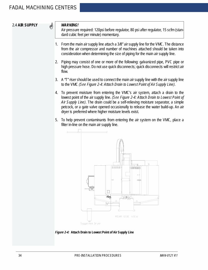
2.4 AIR SUPPLY
34
WARNING!Air pressure required: 120psi before regulator, 80 psi after regulator, 15 scfm (stan-dard cubic feet per minute) momentary.
1. From the main air supply line attach a 3/8” air supply line for the VMC. The distance from the air compressor and number of machines attached should be taken into consideration when determining the size of piping for the main air supply line.
2. Piping may consist of one or more of the following: galvanized pipe, PVC pipe or high pressure hose. Do not use quick disconnects; quick disconnects will restrict air flow.
3. A “T” riser should be used to connect the main air supply line with the air supply line to the VMC (See Figure 2-4: Attach Drain to Lowest Point of Air Supply Line).
4. To prevent moisture from entering the VMC’s air system, attach a drain to the lowest point of the air supply line. (See Figure 2-4: Attach Drain to Lowest Point of Air Supply Line). The drain could be a self-relieving moisture separator, a simple petcock, or a gate valve opened occasionally to release the water build-up. An air dryer is preferred where higher moisture levels exist.
5. To help prevent contaminants from entering the air system on the VMC, place a filter in-line on the main air supply line.
Figure 2-4: Attach Drain to Lowest Point of Air Supply Line
PRE-INSTALLATION PROCEDURES MAN-0121 R1

FANUC MAINTENANCE MANUAL
2.5 ELECTRICAL GROUNDING
AUGUST 2005
WARNING!The importance of proper grounding CANNOT be over-emphasized! Improper grounding will result in a wide range of hard-to-diagnose problems in communica-tions, positioning, spindle motion, etc.
2.5.1 PRIMARY GROUNDING
1. The grounding conductor shall be of copper. The material selected shall be resistant to any corrosive condition existing at the installation or shall be suitably protected against corrosion.
2. The grounding conductor shall be a No. 8 AWG (10 mm2) or larger equipment ground conductor, and must be:
• solid or stranded• insulated, covered, or bare• installed in one continuous length without a splice or joint.
3. Individually covered or insulated grounding conductors shall have a continuous outer finish that is either green, or green with one or more yellow stripes.
4. A No. 8 AWG (10 mm2) or larger equipment ground conductor and 3 phase conductors must be contained within one of the following:
• rigid metal conduit• intermediate metal conduit• electrical metallic tubing
5. The ground conductor shall be connected between the VMC’s ground bus and the approved ground bus contained within the voltage supply panel board or enclosure.
6. The VMC branch supply conduit, phase conductors and ground conductors must be dedicated to a single VMC. They cannot be used to supply any other loads.
2.5.2 SUPPLEMENTAL GROUNDING
1. Supplementary grounding electrodes shall be permitted to augment the equipment grounding conductor; however, the earth shall not be used as the sole equipment grounding conductor.
2. The supplemental grounding conductor shall be a No. 6 (16 mm2) or larger copper conductor in the form of a wire, and must be:
• solid or stranded• insulated, covered or bare• installed in one continuous length without splice or joint
3. A No. 6 (16 mm2) or larger grounding conductor shall be run in one of the following:
• rigid metal conduit
PRE-INSTALLATION PROCEDURES 35

FADAL MACHINING CENTERS
36
• intermediate metal conduit• electrical metallic tubing or cable armor
4. One end of the supplemental grounding conductor shall be attached to the VMC’s ground bus. The other end shall be effectively bonded to a copper cold water pipe that is in direct contact with the earth for 10 feet or more (See Figure 2-5: Bond Grounding Conductor to Copper Cold Water Pipe).
5. Connections shall be made so that they are electrically continuous.
Figure 2-5: Bond Grounding Conductor to Copper Cold Water Pipe
WARNING!Many problems that are difficult to diagnose can occur if the VMC is not properly grounded. Proper grounding cannot be overemphasized.
PRE-INSTALLATION PROCEDURES MAN-0121 R1

FANUC MAINTENANCE MANUAL
2.6 CHECKING GROUNDING INTEGRITY OF FADAL VMCS
2.6.1 SPECIFICATION -GROUNDING FOR THE FADAL MACHINE
AUGUST 2005
1. MUST conferm to NEC code as stated in the Maintenance Manual.
2. MUST be a continuous wire 8 AWG or larger between the VMC's ground bus and the building power distribution panel serving the VMC.
3. MUST be dedicated to a single VMC. (The ground and phase conductors cannot be shared with any other equipment.)
4. Ground rods and other supplemental grounding may be used in addition to the ground specified above but not instead of it.
2.6.2 INSPECTION - CHECK GROUND WIRE COMING INTO VMC
1. The ground wire coming into the VMC and going to the building power distribution panel must be 8AWG or larger.
2. The ground wire must be connected to the ground bar in the back cabinet of the VMC. (It does not go to a screw in the disconnect box.)
3. The ground wire is to be a continuous wire from the VMC to the building power distribution panel serving the VMC. The conduit is not to be used as the grounding conductor. Ground rods and other supplemental grounding may be used in addition to the ground specified above but not instead of it. Servicemen are not the appropriate people to be inspecting power distribution panels or building wiring. The serviceman is not expected to physically verify the routing of the ground conductor, but should look for any indications that grounding is not as specified.
2.6.3 VERIFICATION - CHECK GROUNDING INTEGRITY WITH FLUKE METER
1. Measure the resistance (ohms) of a length of 16AWG or larger wire that is long enough to reach from the VMC to the building power distribution panel that supplies the VMC. Record reading.
2. Attach the wire of step 1 (test wire) to the ground bus of VMC. The other end will be used for measurement at the power distribution enclosure. (Do not open the enclosure. Use a bare screw or bare metal on the enclosure for measurements.)
3. Set meter to AC Volts; with VMC on, measure and record voltage between the test wire and the power distribution enclosure. Set meter to DC Volts; measure and record voltage. Voltages should be OV with machine on but not operating, (up to .O1OV is OK).
PRE-INSTALLATION PROCEDURES 37

FADAL MACHINING CENTERS
38
4. Turn off the VMC and measure the ground voltages (AC and DC) again. Record these readings. Voltages should be OV to .005V.
5. Voltages (AC or DC) across the ground wire will cause false resistance readings. If the ground voltages with VMC off are 0 (.005VAC max.), set meter to ohms and measure resistance between VMC ground bus and power distribution enclosure. Resistance measurement should be less than twice the resistance measured in step 1. (If resistance is negative (due to a ground current), reverse meter leads and average the two readings.)
2.6.4 ELECTRICAL SERVICE
WARNING!Electrical installation of machine must be done by a qualified electrician.
1. The total connected load should not exceed 75% of the panel rating, allowing for the VMC load. Refer to the Electrical Rating Plaque for full load current.
2. If other CNC equipment, motor controllers, motors or electric-discharge lighting (fluorescent, mercury vapor, metal-halide, high and low pressure sodium) are connected to the same panel, the connected load should not exceed 50% of the panels rated capacity.
3. Prior to the installation of the VMC, the panel should be measured for average and peak loads across the three phases.
WARNING!The VMC must NOT be installed on a panel where the measured surge demand current exceeds the panel’s supply amplitude.
2.6.5 PREFERRED SERVICE
The VMC should be supplied by a dedicated circuit connected directly to the Service Entrance panel.
2.6.6 ALTERNATE SERVICE
The VMC may be supplied by a dedicated circuit connected directly to the local branch panel.
PRE-INSTALLATION PROCEDURES MAN-0121 R1

FANUC MAINTENANCE MANUAL
2.6.7 WIRING
AUGUST 2005
Table 2-5: Wiring Requirements
40 Taper 240 VAC 3 Ø 8 AWG (10 mm2) stranded THHN copper within 100 ft. of panel. For VHT 4AWG
6 AWG (16 mm2) stranded THHN copper 100 ft. or more from panel.For VHT 3 AWG
40 Taper 480 VAC 3 Ø 10 AWG (6 mm2) stranded THHN copper within 100 ft. of panel. For VHT 6 AWG
8 AWG (10 mm2) stranded THHN copper 100 ft. or more from panel.For VHT 4 AWG
40 Taper 240 VAC Single Ø 6 AWG (16 mm2) stranded THHN copper within 50 ft. of panel.
4 AWG (25 mm2) stranded THHN copper from 50 to 100 ft. from panel.
50 Taper 480 VAC 3 Ø 4 AWG (25 mm2) stranded THHN copper within 100 ft. of panel.
3 AWG (30 mm2) stranded THHN copper 100 ft. or more from panel.
50 Taper 240 VAC 3 Ø 1AWG (50 mm2) stranded THHN copper within 100 ft. of panel.
1/0 AWG (60 mm2) stranded THHN copper 100 ft. or more from panel.
PRE-INSTALLATION PROCEDURES 39

FADAL MACHINING CENTERS
2.6.8 CONDUIT
40
1. The number and size of conductors in any raceway shall not be more than will permit dissipation of the heat.
2. The conduit must allow ready installation or withdrawal of the conductors without damage to the conductors or to their insulation.
Table 2-6: Conduit Selection
# OF CONDUCTORS
CONDUCTOR SIZE MINIMUM SIZE OF CONDUIT
4 10 AWG THHN (6 mm2) 1/2”
4 8 AWG THHN (10 mm2) 3/4”
4 6 AWG THHN (16 mm2) 3/4”
3 4 AWG THHN (25 mm2) 1.0”
PRE-INSTALLATION PROCEDURES MAN-0121 R1
FANUC MAINTENANCE MANUAL
AUGUST 2005
3.0 INSTALLATION PROCEDURE
WARNING!Before beginning the Machine Installation & Hook-Up it is important to review the entire Installation Procedure section.
INSTALLATION PROCEDURE 41
FADAL MACHINING CENTERS
3.1 MACHINE INSTALLATION & HOOK-UP
3.1.1 UNPACKING
42
Tools Required
Hammer, 15/16” socket or wrench and knife
1. Remove the crate and/or protective material from around the VMC.
2. Remove the strapping material from the front doors.
3. Unload the boxes from the inside and/or around the VMC.
4. Remove each of the four 5/8” bolts and nuts between the base of the VMC and the pallet.
3.1.2 PLACING THE VMC
1. Place the leveling pads (countersink side up) under the leveling bolts. Be sure leveling bolts go into countersink on leveling pads.
NOTE Use leveling pad SHP-0002 (PLC-0063 for slant sheet metal machines, or machines equipped with the HydroSweep option) for placing the machine. Any other pad may cause damage to the machine.
2. Remove the fork lift bars or the eye bolts and the steel bar from the column.
INSTALLATION PROCEDURE MAN-0121 R1

AUGUST 2005
FANUC MAINTENANCE MANUAL
3. At this point the VMC is ready for power and air connections.
Figure 3-1: Placing the VMC
minimum bar length 36”Hole procided for 1-1/4” bar
1-8”eye bolt 2 places1.5” eye bolt 2 places for 6535
Maximum fork width is 6.00”
3.1.3 AIR SUPPLY
WARNING!AIR PRESSURE REQUIRED: 120 psi before regulator, 80 psi after regulator, 15 scfm (standard cubic feet per minute) momentary.1. Connect the 3/8” air hose to the VMC.
INSTALLATION PROCEDURE 43

FADAL MACHINING CENTERS
44
2. Check the pressure gauge for 120 psi and adjust the regulator on the VMC if necessary.
3. Check for air leaks at the fitting and around the air regulator.
4. It is important that the air compressor turns on when the pressure drops to approximately 120 psi. This assures the VMC a constant 80 psi.
3.1.4 POWER CHECK
WARNING!Do NOT power on the VMC before completing this section.Tools Required
Fluke DMM, screwdriver or Wago tool 210-141
(ST-26), 5/16” hex bit socket and 3/4” open or box wrench.
Verify the Main Power Fuses
With the main disconnect switch in the off (down) position, open the cover to the main disconnect box.
INSTALLATION PROCEDURE MAN-0121 R1
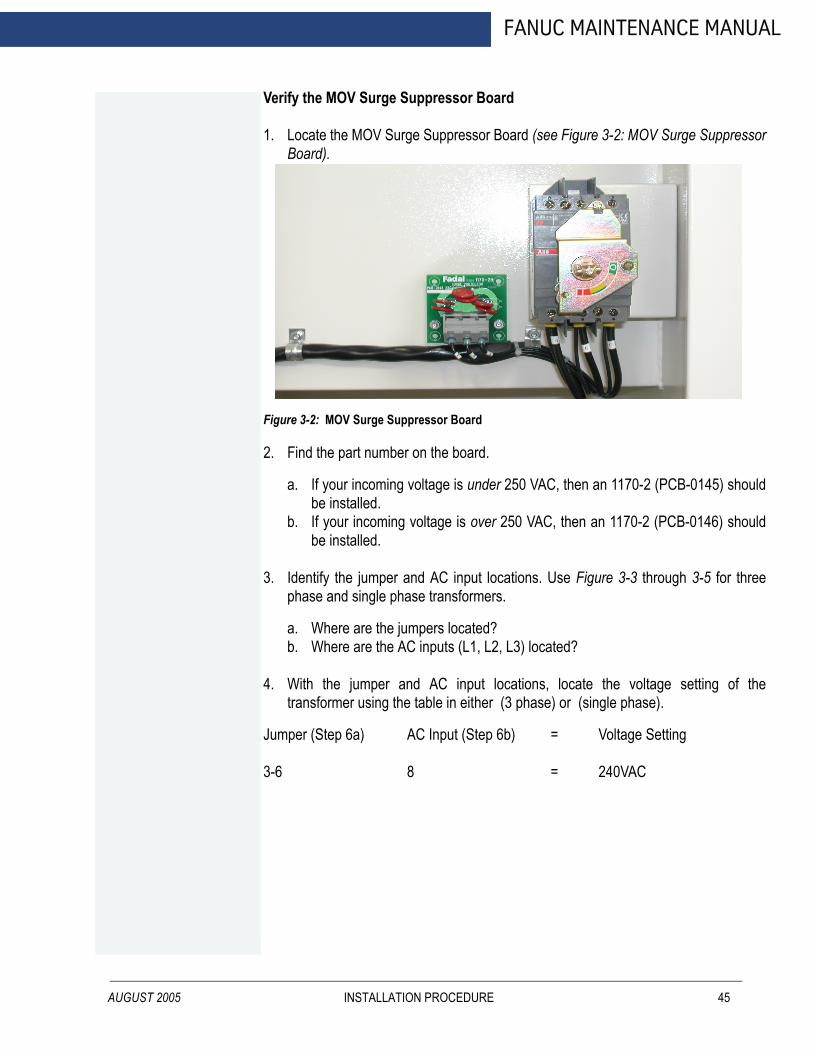
AUGUST 2005
FANUC MAINTENANCE MANUAL
Verify the MOV Surge Suppressor Board
1. Locate the MOV Surge Suppressor Board (see Figure 3-2: MOV Surge Suppressor Board).
Figure 3-2: MOV Surge Suppressor Board
2. Find the part number on the board.
a. If your incoming voltage is under 250 VAC, then an 1170-2 (PCB-0145) should be installed.
b. If your incoming voltage is over 250 VAC, then an 1170-2 (PCB-0146) should be installed.
3. Identify the jumper and AC input locations. Use Figure 3-3 through 3-5 for three phase and single phase transformers.
a. Where are the jumpers located?b. Where are the AC inputs (L1, L2, L3) located?
4. With the jumper and AC input locations, locate the voltage setting of the transformer using the table in either (3 phase) or (single phase).
Jumper (Step 6a) AC Input (Step 6b) = Voltage Setting
3-6 8 = 240VAC
INSTALLATION PROCEDURE 45
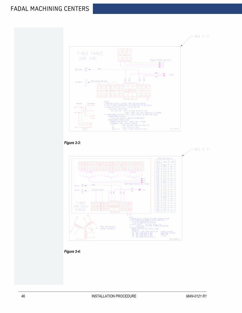
FADAL MACHINING CENTERS
46
Figure 3-3:
Figure 3-4:
INSTALLATION PROCEDURE MAN-0121 R1

AUGUST 2005
FANUC MAINTENANCE MANUAL
Figure 3-5:
The VMC is Ready for the Initial Power on Procedure
1. Move the main disconnect switch to the ON (up) position.
2. Measure the voltage at the transformers secondary between A12-B12, A12-C12, B12-C12.
3. For single phase measure across A8-C8. The voltage should be between 230-240 VAC, correct if necessary.
4. Push the EMERGENCY STOP switch to disable the axes, then push the CNC POWER button.
5. Check the voltages on the D.C. power supply, i.e. 5, + 12, -12 VDC.
6. Reset the EMERGENCY STOP switch.
7. Unbolt and remove the support between the table and the head.
8. Unbolt and remove the counterweight bars from the column, located next to the main disconnect box.
9. Jog the axis to the cold start indicators and cold start the VMC.
INSTALLATION PROCEDURE 47
FADAL MACHINING CENTERS
3.2 TRANSFORMER TAPPING
48
1. With the machine main power switch turned OFF, verify that the chart on the door of the cabinet is the one for the transformer in the machine.
2. Measure the input voltage to the machine on the chart (Measure leg to leg the input power lines to the machine.).
3. Next to the voltage on the chart will be a “jumper” number, such as 3-6, and a “AC Input” number, such as 7.
4. Each phase has a group of terminals such as A3 to A8 for phase 1 and B3 to B8 for phase 2. Place a jumper between the two terminals listed on the chart for each phase. Using the same example place jumper from A3 to A6 for phase 1, B3 to B6 for phase 2 and one from C3 to C6 for phase 3.
5. Place the input tap wire in the proper terminal, as in example A7 for phase 1, B7 for phase 2 and C7 for phase 3.
6. Turn ON the main power switch.
7. Measure the input voltage to the spindle drive, usually labeled L1, L2 & L3, leg to leg. Should be about 230 VAC with the range being from 220 to 240 VAC. If the difference between 230 and the measured voltage is greater then ten (10) volts then power down. If the voltage is too high then select the next higher voltage on the chart and change the jumper and / or input tap and recheck. If the voltage is too low then select the next lower voltage and change and check.
NOTE It is acceptable to have the legs tapped differently by one voltage tap position. There should be no more than one position.
INSTALLATION PROCEDURE MAN-0121 R1

FANUC MAINTENANCE MANUAL
3.3 SINGLE PHASE INPUT POWER
AUGUST 2005
The Fadal VMC line is designed for three phase input power. However, three-phase power is not always available. If this is the case, Fadal offers a single-phase input power option. Most Fadal machines are capable of operating on single-phase line input. The torque ratings will be at 60% of the published performance. The rapid traverse rate is reduced to not more than 700 IPM for machines with higher speed capability. This is because as the DC bus capacitors are drained and the bus voltage drops, the single-phase input can not recharge the capacitors as fast as the three-phase. Lower bus voltage equals lower speed and more current. Single-phase requires 73% more current to maintain the same performance (square root of 3). The main limitation is the spindle drive. It will not draw more than its rated current. The current rise is steeper in single-phase and will, therefore, trip sooner.
Fadal does not recommend single-phase power for the High torque or the 6535, 6030 and 8030 machines and cannot be used with VHT or 50 taper. This option can be ordered on a new machine and can be installed in the field. Some wiring changes are also necessary. Please see the single-phase transformer charts and wiring instructions.
INSTALLATION PROCEDURE 49

FADAL MACHINING CENTERS
3.4 PHASE CONVERTER ROTARY
50
The normal Fadal VMC requires three phase-input power. The machines are also configured in a single-phase power configuration when requested. Some customers prefer to use rotary phase converters. However, Fadal does not recommend the use of rotary phase converters.
Rotary phase converters input single-phase 208 to 230 VAC and output three phase 230 VAC. For a VMC close to a 5% voltage balance between legs is desirable, in reference to the voltage differences of each phase. Most CNC machines would require the output power to be 1-1/2 to 2 times larger than the spindle motor (for a Fadal output must be at or higher than the minimum of the required input; see Specifications, Section 1.0, MAN-0121 R1). A Voltage Stabilizer may also be required. The stabilizer’s function is to maintain a consistent voltage level of the three phases during light or no load conditions.
INSTALLATION PROCEDURE MAN-0121 R1

FANUC MAINTENANCE MANUAL
3.5 LEVELING
AUGUST 2005
Leveling is an important first step in setting up the VMC. All calibration and squareness performed on the assembly line is done with the machine leveled. It is important to follow the sequence below precisely to ensure proper results.
Tools Required
Precision Level, such as the Starrett 12”, P/N 199Z
WARNING!Verify that the scale reads the same when rotated 180 degrees.If using a flashlight to see the bubble, do not place the flashlight on the level, as it will warm the bubble and give an incorrect reading.
3.5.1 FOR ALL BOX WAY VMCS
1. The VMC should be positioned on one solid concrete slab (see Pre-Installation,section 2, MAN-0121 R1). Do not straddle any cracks or seams.
2. Center the leveling pads under the leveling screws.
3. Level the VMC as close as possible to the leveling pads. The leveling screws should be extended as little as possible to reduce vibration through the sheet metal.
NOTE Make sure that machines with the chip conveyor option are raised high enough so that the chip conveyor tank fits under the sheet metal of the VMC.
4. Verify the Cold Start indicators, then cold start the VMC.
5. Clean the level with alcohol.
6. Jog the Y axis to the Y+ limit.
7. Clean the outer base ways with alcohol.
INSTALLATION PROCEDURE 51

FADAL MACHINING CENTERS
52
8. Place the level on the right hand way (the outer right hand way on the 6535) of the base with the small bubble towards the column. Take an accurate reading. (See Figure 3-6: Leveling Box Way.)
Figure 3-6: Leveling Box Way.
9. Now put the level on the left hand way (the outer left hand way on the 6535) of the base with the level pointing in the same direction as on the right hand way.
10. Adjust the leveling screws on the machine until the left hand way and the right hand way level are even.
11. The level will have a front to back bubble and a side to side bubble. Level the machine from front to back first and then from side to side. When adjusting the side to side, adjust both leveling screws of one side only.
12. If leveling larger machines, such as the 6535, 6030 or 8030 models, the center four leveling screws must not be touching the leveling pads during the leveling procedure. After the machine has been leveled, lower the four screws to the pad, then check the level and tram readings to ensure they have not changed.
INSTALLATION PROCEDURE MAN-0121 R1

AUGUST 2005
FANUC MAINTENANCE MANUAL
13. Verify the spindle tram and, if necessary, adjust by slightly changing only the two front leveling screws.
INSTALLATION PROCEDURE 53

FADAL MACHINING CENTERS
3.6 HOLD DOWN CLAMPS
54
Larger machines may vibrate, bump on reversals, and degrade floor finish.
This may indicate that the base casting needs to be clamped to floor.
Larger machines need to be clamped to the floor to prevent movement between the machine and the floor, and clamping holes are provided on all base castings for this purpose.
The kit SHP-0116 has been developed to mount the machine to the floor without moving it.
1. The Clamp is first mounted into the clamping hole in the base.
2. The position is marked on the floor for drilling a ½” hole into the concrete.
3. The RedHead stud is mounted in the floor with one nut and washer on it.
4. The Clamp is mounted over the stud and then the two ½ inch Socket Cap screws are tightened, pinching the flange of the base casting.
5. The second washer and nut are tightened onto the stud, inhibiting any flexing up or down of the base casting.
6. Recheck machine level.
Hilti (mfg in Liechtenstein) makes a Right-Angle Hammer Drill, model TE-5, with a model TE-AC Right Angle Head attachment, that works very well in this application.
INSTALLATION PROCEDURE MAN-0121 R1

FANUC MAINTENANCE MANUAL
3.7 OPTICAL FIBER CABLE HANDLING
AUGUST 2005
Careful handling of Optical Fiber Cable:
1. Even though reinforcing cover used on the optical fiber code has enough mechani-cal strength, be sure not to be damaged by heavy materials drop.
2. Detaching and attaching of optical connector should always be made by touching connector. Optical fiber code should not be touched when replacement.
3. Optical connector is automatically locked with upper side lock levels after being connected. It is impossible to pull out the connector without releasing the lock lev-els.
4. Optical connector can not be connected oppositely. Be sure the connector direction when connection is done.
5. Optical connector should be processed as follows before laying of optical fiber cable.
Fix a reinforcing cover to a wire with hook or tension member by a tape. At laying hook the wire or pull the tension member taking enough care that optical connector does not receive pulling strength.
6. Reinforcing cover is fixed to cable lamp so that optical fiber cable could not weight directly the connecting part of connector.
7. Notice that optical connector’s chip is clear. The attached protect cap must be always put on when optical connector is not used.
8. Remove dirt with a clear tissue or absorbent cotton (cotton with ethyl alcohol is applicable). No other organic solvent than ethyl alcohol can be used.
INSTALLATION PROCEDURE 55
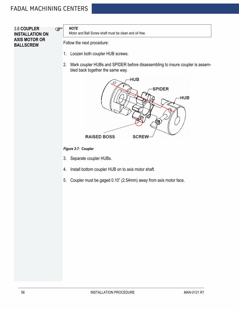
FADAL MACHINING CENTERS
3.8 COUPLER INSTALLATION ON AXIS MOTOR OR BALLSCREW
56
NOTE Motor and Ball Screw shaft must be clean and oil free.
Follow the next procedure:
1. Loozen both coupler HUB screws.
2. Mark coupler HUBs and SPIDER before disassembling to insure coupler is assem-bled back together the same way.
Figure 3-7: Coupler
3. Separate coupler HUBs.
4. Install bottom coupler HUB on to axis motor shaft.
5. Coupler must be gaged 0.10” (2.54mm) away from axis motor face.
INSTALLATION PROCEDURE MAN-0121 R1
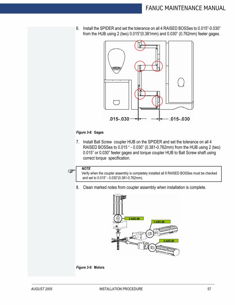
AUGUST 2005
FANUC MAINTENANCE MANUAL
6. Install the SPIDER and set the tolerance on all 4 RAISED BOSSes to 0.015”-0.030” from the HUB using 2 (two) 0.015”(0.381mm) and 0.030” (0.762mm) feeler gages.
Figure 3-8: Gages
7. Install Ball Screw coupler HUB on the SPIDER and set the tolerance on all 4 RAISED BOSSes to 0.015 “ - 0.030” (0.381-0.762mm) from the HUB using 2 (two) 0.015” or 0.030” feeler gages and torque coupler HUB to Ball Screw shaft using correct torque specification.
NOTE Verify when the coupler assembly is completely installed all 8 RAISED BOSSes must be checked and set to 0.015” - 0.030”(0.381-0.762mm).
8. Clean marked notes from coupler assembly when installation is complete.
Figure 3-9: Motors
Z-AXIS 8ft Y-AXIS 8ft
X-AXIS 8ft
INSTALLATION PROCEDURE 57

FADAL MACHINING CENTERS
58
Figure 3-10: Motors
Table 3-1: Couplers
MACHINE X AXIS Y AXIS Z AXISEMC KTR ROTEX GS
24.625x24mmKTR ROTEX GS
24.625x24mmKTR ROTEX AI GS
24.625x19mm22163016402060308030
5020A4020A3016L KTR ROTEX GS 24.625x24mm2016L KTR ROTEX AI GS 24.625x19mm
Table 3-2: Couplers
MACHINE X AXIS Y AXIS Z AXIS3020 KTR ROTEX GS
24.625x24mmKTR ROTEX GS
24.625x24mmKTR ROTEX AI GS
24.625x19mm45256535/40T KTR ROTEX GS
24.625x24mm6535/50T
Z-AXIS 19ft X-AXIS 8ft
Y-AXIS 8ft
INSTALLATION PROCEDURE MAN-0121 R1
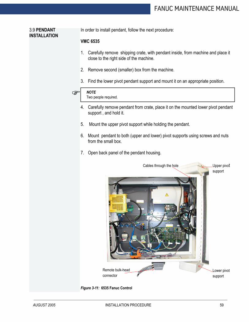
FANUC MAINTENANCE MANUAL
3.9 PENDANT INSTALLATION
AUGUST 2005
In order to install pendant, follow the next procedure:
VMC 6535
1. Carefully remove shipping crate, with pendant inside, from machine and place it close to the right side of the machine.
2. Remove second (smaller) box from the machine.
3. Find the lower pivot pendant support and mount it on an appropriate position.
NOTE Two people required.
4. Carefully remove pendant from crate, place it on the mounted lower pivot pendant support , and hold it.
5. Mount the upper pivot support while holding the pendant.
6. Mount pendant to both (upper and lower) pivot supports using screws and nuts from the small box.
7. Open back panel of the pendant housing.
Figure 3-11: 6535 Fanuc Control
Upper pivotsupport
Lower pivotsupport
Cables through the hole
Remote bulk-headconnector
INSTALLATION PROCEDURE 59
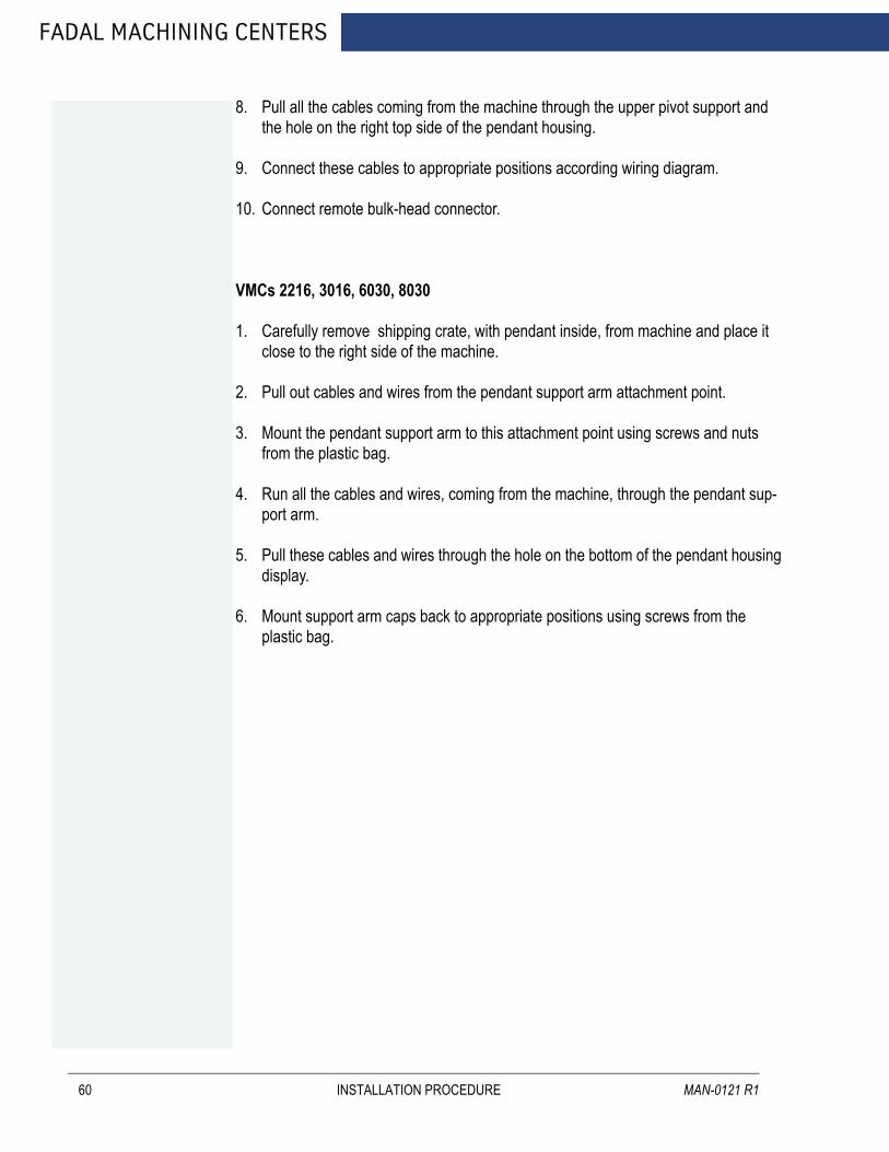
FADAL MACHINING CENTERS
60
8. Pull all the cables coming from the machine through the upper pivot support and the hole on the right top side of the pendant housing.
9. Connect these cables to appropriate positions according wiring diagram.
10. Connect remote bulk-head connector.
VMCs 2216, 3016, 6030, 8030
1. Carefully remove shipping crate, with pendant inside, from machine and place it close to the right side of the machine.
2. Pull out cables and wires from the pendant support arm attachment point.
3. Mount the pendant support arm to this attachment point using screws and nuts from the plastic bag.
4. Run all the cables and wires, coming from the machine, through the pendant sup-port arm.
5. Pull these cables and wires through the hole on the bottom of the pendant housing display.
6. Mount support arm caps back to appropriate positions using screws from the plastic bag.
INSTALLATION PROCEDURE MAN-0121 R1
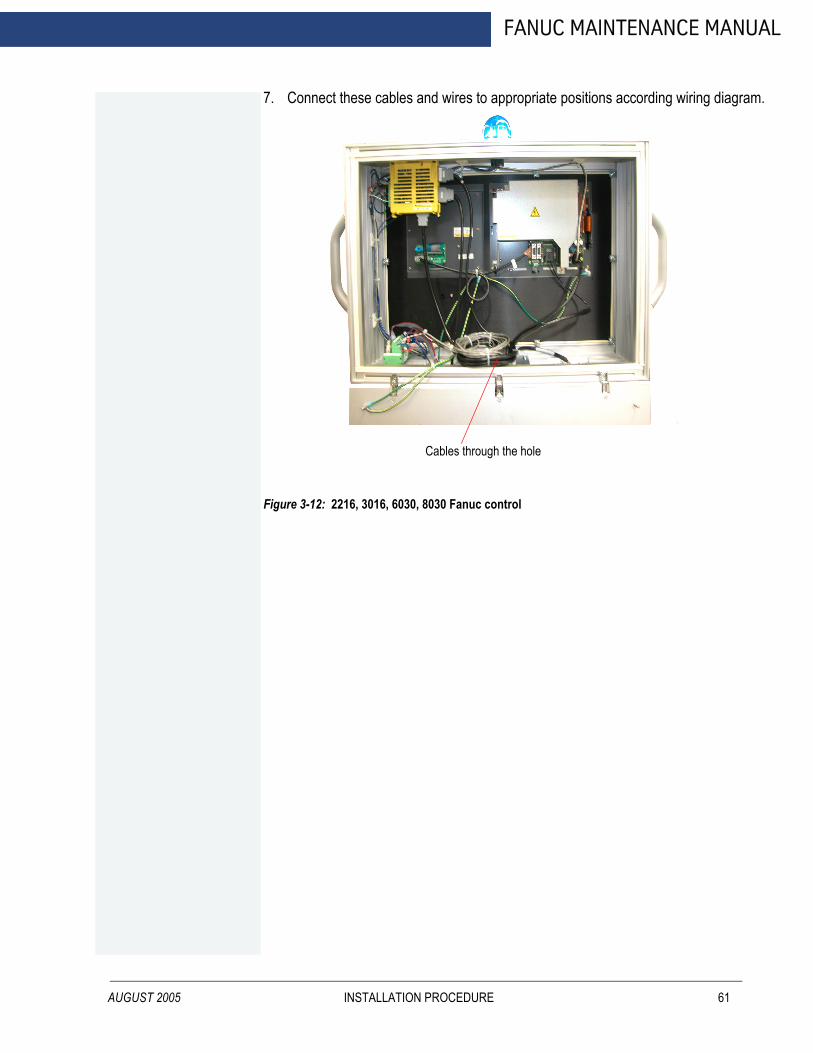
AUGUST 2005
FANUC MAINTENANCE MANUAL
7. Connect these cables and wires to appropriate positions according wiring diagram.
Figure 3-12: 2216, 3016, 6030, 8030 Fanuc control
Cables through the hole
INSTALLATION PROCEDURE 61

FADAL MACHINING CENTERS
3.10 GENERAL
62
Dettach column breaks from spindle head and tool changer arm.
Figure 3-13: Column breaks
Place the cable carrier (black flexible arc on top of the machine) onto appropriate screws and tight them with nuts.
Figure 3-14: Cable carrier
Column breaksside view front view
INSTALLATION PROCEDURE MAN-0121 R1
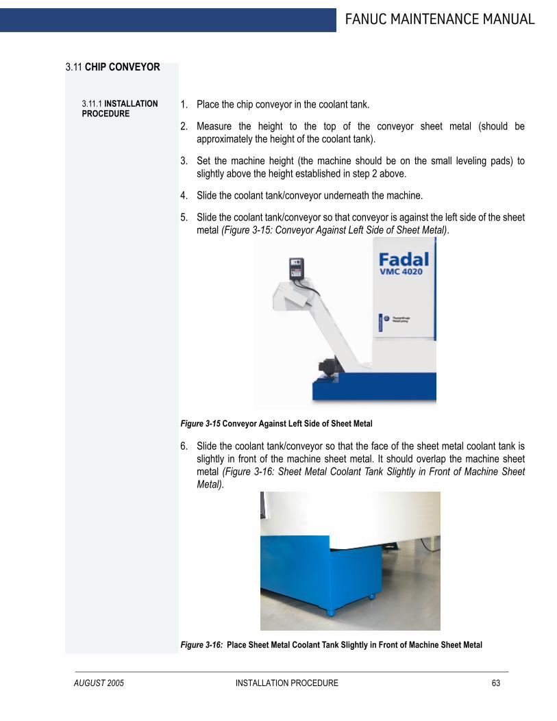
FANUC MAINTENANCE MANUAL
3.11 CHIP CONVEYOR
3.11.1 INSTALLATION PROCEDURE
AUGUST 2005
1. Place the chip conveyor in the coolant tank.
2. Measure the height to the top of the conveyor sheet metal (should be approximately the height of the coolant tank).
3. Set the machine height (the machine should be on the small leveling pads) to slightly above the height established in step 2 above.
4. Slide the coolant tank/conveyor underneath the machine.
5. Slide the coolant tank/conveyor so that conveyor is against the left side of the sheet metal (Figure 3-15: Conveyor Against Left Side of Sheet Metal).
Figure 3-15 Conveyor Against Left Side of Sheet Metal
6. Slide the coolant tank/conveyor so that the face of the sheet metal coolant tank is slightly in front of the machine sheet metal. It should overlap the machine sheet metal (Figure 3-16: Sheet Metal Coolant Tank Slightly in Front of Machine Sheet Metal).
Figure 3-16: Place Sheet Metal Coolant Tank Slightly in Front of Machine Sheet Metal
INSTALLATION PROCEDURE 63
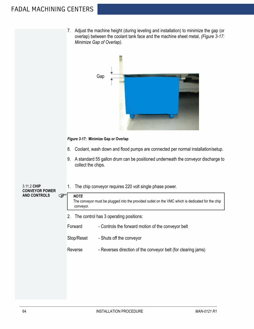
FADAL MACHINING CENTERS
64
7. Adjust the machine height (during leveling and installation) to minimize the gap (or overlap) between the coolant tank face and the machine sheet metal, (Figure 3-17: Minimize Gap of Overlap).
Figure 3-17: Minimize Gap or Overlap
8. Coolant, wash down and flood pumps are connected per normal installation/setup.
9. A standard 55 gallon drum can be positioned underneath the conveyor discharge to collect the chips.
Gap
3.11.2 CHIP CONVEYOR POWER AND CONTROLS
1. The chip conveyor requires 220 volt single phase power.
NOTE The conveyor must be plugged into the provided outlet on the VMC which is dedicated for the chip conveyor.
2. The control has 3 operating positions:
Forward - Controls the forward motion of the conveyor belt
Stop/Reset - Shuts off the conveyor
Reverse - Reverses direction of the conveyor belt (for clearing jams)
INSTALLATION PROCEDURE MAN-0121 R1

AUGUST 2005
FANUC MAINTENANCE MANUAL
3. The control also has a variable speed control for the belt speed. The belt speed can be controlled from 2.60 ft./min. to 10.80ft/min.
Figure 3-18: Control Operating Positions
Figure 3-19: Emergency Stop (CE machines only)
INSTALLATION PROCEDURE 65

FADAL MACHINING CENTERS
66
INSTALLATION PROCEDURE MAN-0121 R1
FANUC MAINTENANCE MANUAL
AUGUST 2005
4.0 MACHINE MAINTENANCE
MACHINE MAINTENANCE 67
FADAL MACHINING CENTERS
4.1 SCHEDULED MAINTENANCE
4.1.1 MAINTENANCE & LUBRICATION SCHEDULE
68
Daily
1. Check air pressure: Right regulator 120 psi. max. (Tool Out Only). Left Regulator80-90 psi.
2. Check way lube level. Use Castrol Magna BD68, Shell Tonna 68V or Mobil Vactra#2 ONLY.
3. Check way lube system for adequate oil flow to all way surfaces.
4. With tool in spindle blow chips from around ATC and slide. NEVER blow chips fromaround these areas during automatic tool change or without a tool in the spindle.
5. Remove heavy chip build up from guards and way covers.
6. Wash ATC and machine work area.
7. Check coolant level.
8. Clean coolant screen.
9. Clean the area around the machine.
10. Immediately clean any spills in the area.
Weekly
1. Check spindle cooler pump and refrigeration unit for proper operation.
2. Check fluid level of chiller tank and refill, if needed, with a 50/50 mix ofDOWFROST™ CLEAR and de-ionized water. If de-ionized water is not available,sodium-free distilled water can be substituted. Do not accept any substitutes forDOWFROST™ CLEAR!
3. Clean ATC slide.
4. Check air regulator.
5. Drain and clean water separator.
6. Fill oiler if needed.
7. Activate thru-tool coolant system for 2-3 minutes (if machine has this option).
8. Grease axis way cover using molygraph.
9. Grease retention rings using molygraph.
MACHINE MAINTENANCE MAN-0121 R1
AUGUST 2005
FANUC MAINTENANCE MANUAL
10. Grease Geneva wheel and gear using Kopr-Kote.
11. For high torque machines, check fluid level in the hydraulic actuator reservoir.Refill, if needed, with Mobil DTE Heavy Medium.
12. Inspect all cooling fans, clean screens if necessary.
Every 4 months
Service way lube filter. Machines with an external filter require less frequent replacement; however, do not exceed 4 months. When replacing the external filter, fill the new filter with way lube prior to installation.
4.1.2 LUBRICATION OF THE WAYS
Waylube System
Use waylube type Castrol Magna BD68, Shell Tonna 68V or Mobil Vactra Oil #2.
The Positive Displacement Injection (PDI) lube system is a solenoid-controlled pneumatic system. When the solenoid is activated, the pump sends oil to the junction block assemblies, which may contain several different size valves, at a pressure ratio of 5:1. The pump is activated for 10 seconds, within a 4 minute cycle, during which oil is distributed to all of the valves on the junction block assemblies. When the solenoid is deactivated the oil flow stops and creates back pressure which escapes through a relief valve. When the pressure on the valve drops below 50 psi, a spring inside the valve is then able to inject oil into the lines.
The CNC has direct control of the automatic lube system. The cycle is activated by executing an axis motion in a CNC program, commanding an axis move in MDI mode or pressing the JOG key. Once activated it monitors the oil level to be sure the reservoir is above the minimum level. In addition, it shuts the oil system down if the machine sits idle longer than one cycle of the lube system.
Frequently clogging filters indicate that the wrong waylube is being used. Use Castrol Magna BD68, Shell Tonna 68V or Mobil Vactra Oil #2 ONLY.
Procedure for Flushing a Contaminated Waylube System
This procedure is necessary when the waylube that was being used in the machine was incorrect. Other waylubes may contain paraffin wax or silicone.
1. Replace the 10-port way lube junction block that is located at the left side of thesaddle.
2. Replace the External filter on the BIJUR PDI way lube pump (Part # LUB-0049).
MACHINE MAINTENANCE 69

FADAL MACHINING CENTERS
70
3. Remove the oil line that is between the way lube pump and the three port junction Tthat is located near the pump mount.
4. Verify that the flush pump air regulator is fully counterclockwise.
5. Attach an air line to the flush pump.
WARNING!Verify that the air regulator is closed.
6. Insert the 3/8" hose from the flush pump into a container of grade A kerosene.
7. Slowly open the air regulator clockwise to start the flush pump.
8. Increase the air pressure being careful that the output pressure does not exceed180 psi at the gauge.
9. The pump is 4:1 ratio, 45 psi input air pressure is 180 psi output.
10. Enter a program that will exercise all axes to their limits. Start running the program.
11. The flow of kerosene through the way lube system should be steady.
12. If the kerosene is dripping slowly down the column from underneath the Z axishead the manifold filters are probably clogged. Replace the eight-port junctionblock located on the Z axis head. Start over at step D.
13. Remove the 3/8” hose from the kerosene and place the hose in a can of clean freshwaylube.
14. Slowly open the regulator clockwise on the flush pump. Pump waylube through thelines until the system is well lubricated.
15. Stop the machine and return it to the COLD START position.
16. Turn the flush pump air regulator fully counterclockwise and remove the air line.
17. Remove the flush pump and reattach the oil line from the Bijur pump to the 3 portjunction.
4.1.3 COOLING FANS
WARNING!Power off the machine at the main disconnect switch and lockout/tagout the main disconnect.There are numerous cooling fans on the VMC that require periodic inspection. Located in the CNC box and the junction box.
MACHINE MAINTENANCE MAN-0121 R1

AUGUST 2005
FANUC MAINTENANCE MANUAL
WARNING!Wear safety glasses!
If the fan is turning slowly or not at all, it may require cleaning or replacement. The fan on the bottom of the junction box has a screen that requires periodic inspection and removal for cleaning.
4.1.4 SPINDLE & BALLSCREW COOL-ING SYSTEM
The spindle and ballscrew cooling system is made up of a motor pump assembly, ambient-liquid temperature sensor assembly and a DP5P chiller. As long as there is power to the machine the chiller pump is circulating DOWFROST™ through the system. The ambient sensor is used to measure casting/air temperature and the liquid sensor to measure Dowfrost temperature in the return line. When there is a one degree temperature differential between the two sensors the chiller is then powered on.
4.1.5 PUMP FILTER
There is a small filter and pressure gauge located on the pump head assembly. Normal pressure is 3-5 pounds, cooled ball screws are 10 to 30 pounds. If the pressure gauge shows a pressure above normal the filter should be inspected and cleaned.Figure 4-1 Pump Filter
Filter
MACHINE MAINTENANCE 71
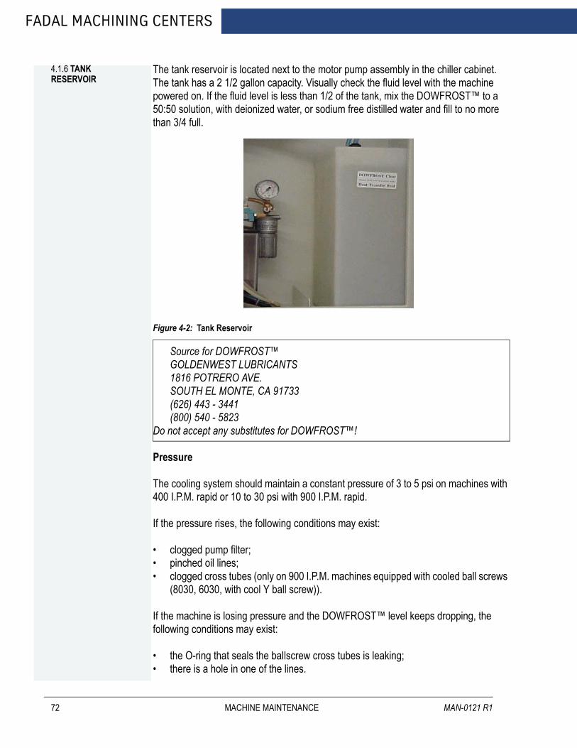
FADAL MACHINING CENTERS
4.1.6 TANK RESERVOIR
72
The tank reservoir is located next to the motor pump assembly in the chiller cabinet. The tank has a 2 1/2 gallon capacity. Visually check the fluid level with the machine powered on. If the fluid level is less than 1/2 of the tank, mix the DOWFROST™ to a 50:50 solution, with deionized water, or sodium free distilled water and fill to no more than 3/4 full.
Figure 4-2: Tank Reservoir
Source for DOWFROST™GOLDENWEST LUBRICANTS1816 POTRERO AVE.SOUTH EL MONTE, CA 91733(626) 443 - 3441(800) 540 - 5823
Do not accept any substitutes for DOWFROST™!
Pressure
The cooling system should maintain a constant pressure of 3 to 5 psi on machines with 400 I.P.M. rapid or 10 to 30 psi with 900 I.P.M. rapid.
If the pressure rises, the following conditions may exist:
• clogged pump filter; • pinched oil lines; • clogged cross tubes (only on 900 I.P.M. machines equipped with cooled ball screws
(8030, 6030, with cool Y ball screw)).
If the machine is losing pressure and the DOWFROST™ level keeps dropping, the following conditions may exist:
• the O-ring that seals the ballscrew cross tubes is leaking;• there is a hole in one of the lines.
MACHINE MAINTENANCE MAN-0121 R1

FANUC MAINTENANCE MANUAL
4.1.7 FLUIDS
AUGUST 2005
Table 4-1: Fluids
RESERVOIR FILL WITHWaylube CASTROL MAGNA BD68
SHELL TONNA 68Vor MOBIL VACTRA #2
Spindle Cooling System DOWFROST™ CLEAR(Mixed 50/50 with de-ionized water or sodium free distilled water)
Rotary Tables MOBIL GEAR 626Hydraulic Hi/Low MOBIL DTE HEAVY MEDIUMHydraulic Brake HYDRAULIC OIL 32Spindle Oil (air/oil) UNI-LUBE 32
MACHINE MAINTENANCE 73

FADAL MACHINING CENTERS
4.1.8 DUAL ARM TOOL CHANGER
74
The causes of abnormal wear and fractures will be apparent when the tool changer is used without lubricant. It is very important to grease all moving parts of the tool changer at least once a week.
Lubricant
The lubricant should be changed annually, or when it has become visibly deteriorated. The recommended lubricant is SAE 90-140. The DATC uses approximately 5 liters of lubricant (1.3 gallons).
Grease
Grease should be spread once a week in the following locations:
1. The claws of the tool changing arm unit.
2. The tip of the release pin of the tool changing arm unit.
Cleaning
1. Remove the chip powder from around the proximity switch inducing box.
2. Remove the chip powder from around the inverted moving body of the tool pot.
3. The tool changing mechanism must be cleaned frequently to prevent excess buildup of chip powder.
Inspection
Check the parts of the tool falling mechanism regularly and, check for grease on the sliding base of the tool falling mechanism and the sliding base of the pull rod. Check the parts of the tool pots and tool discs for tightness and overall condition.
4.1.9 SCHEDULED MAINTENANCE FOR DUAL ARM TOOL CHANGER
The maintenance schedule is based on machine usage of eight hours a day, five days a week.
Daily Maintenance
Perform the following daily:
1. Cleaning
a. Remove the chips and debris surrounding the proximity switch inducing block.b. Remove the chips and debris that have accumulated on the inverted moving
body of the tool pot.c. Clear the tool changing mechanism of all debris before any operation.
MACHINE MAINTENANCE MAN-0121 R1

AUGUST 2005
FANUC MAINTENANCE MANUAL
2. Inspection:
a. Check the parts of the tool falling mechanism for damage and wear. Addgrease to the sliding base of the tool falling mechanism and the pull rod.
b. Check the parts of the tool pots, tool discs, and snap rings for damage andtightness.
Grease Maintenance
1. Perform the following weekly:
a. Grease the claws of the tool changing arm unit.b. Grease the tip of the release pin of the tool changing unit.
2. Check and replenish the following parts with grease every six months:
Lubricant Maintenance
The lubricant inside the lubricant container of tool changing mechanism should be changed after working for 2400 hours. When the cam, rollers and bevel gear are in use without lubricant abnormal wear and fractures will occur. Appropriate quantity of lubricant should be a little more than half of the lubricant container.
Change the lubricant annually or as needed. The recommended lubricant is SAE 90-140. The Dual Arm Tool Changer uses approximately :
40T fill oil to the middle line of oil glass about 6L (1.5 gallons)50T fill oil to the middle line of oil glass about 10L (2.5 gallons).
SECTION PARTS NAMEToo magazine Driving roller
Index mechanism Cylindrical camTool pot Roller wheelTool arm Plunger
Tool holding rod
MACHINE MAINTENANCE 75
FADAL MACHINING CENTERS
4.2 TESTS FOR CE SAFEGUARDS ON FADAL MACHINES
76
These tests should be done when machine is first installed and after servicing when any components are replaced.
1. Power on machine but do reference.
Start spindle. (Press Shift-Spindle on)
• Spindle will not start OR• Press Emergency Stop; spindle must stop. • Immediately release Emergency Stop; spindle does not start.
2. Reference machine.
Start spindle.
• Press Emergency Stop; spindle must stop. • Immediately release Emergency Stop; spindle shall not start, VMC remains in
emergency stop.• Repeat test in Auto, MDI, and Jog modes.
3. Start spindle. (Press Shift-Spindle on)
• Open front door; spindle must stop. • Try to restart spindle; spindle does not start with doors open.• Check contactor for spindle; contacts should be out. (There may be a 5 to 10 sec-
ond delay between the opening of the door and the release of the contactor. This allows a controlled stop).
4. Close doors.
• Repeat test with left side panel.• Repeat test with right side panel.
MACHINE MAINTENANCE MAN-0121 R1

AUGUST 2005
FANUC MAINTENANCE MANUAL
Daily & Weekly Safety Tests for CE Safety Circuits
To ensure proper functioning of safety circuits, the following tests should be performed on a regular basis.
Daily
Front Door Lock Daily Test for 2030-OA
1. Close all doors. Make sure machine is not in emergency stop.
2. Open front door. You may be able to hear the spindle contactor open, if not asecond person will be needed to watch the contactor.
3. Close front door. You may be able to hear the contactor close, if not see 2 above.
4. Start spindle. Attempt to open front door. Front door should be locked.
5. Stop spindle. There should be a delay of 1 to 5 seconds after the spindle comes toa complete stop before the door unlocks. (This delay can be adjusted from 1 to 5seconds .)
6. In either automatic or manual mode command a tool change. Attempt to open thedoor. Front door should be locked while turret is moving toward spindle or whiledual arm tool changer arm is in motion.
Dual Arm Tool Changer Daily Test
No daily test.
MACHINE MAINTENANCE 77
FADAL MACHINING CENTERS
4.3 CHIP CONVEYOR
78
4.3.1 MAINTENANCE SCHEDULE CHIP CONVEYOR
Please carry out daily, monthly, and yearly inspection according to the following directions.
Daily Inspection
1. Always keep oil in the speed reducer at the specified oil level.
2. Check motor for abnormal operation, i.e. noise, heat excessive current, etc.
3. Lubricate conveyor chain and roller chain every 150 hours.
4. Discard chips on the surface of the belt and inside of frame (place a rag on the beltand reverse until the rag is discarded).
Monthly Inspection
1. Change oil at 100 hours initially, every 1,500 to 2,000 hours thereafter.
2. Check motor for abnormal operation, i.e. noise, heat excessive current, etc.
3. Keep correct tension of conveyor chain by adjusting take-up bearing.
4. Check roller chain between motor and conveyor for proper alignment and correcttension.
5. The greatest care should be exercised to keep friction surface of torque limiter freefrom oil when lubricating roller chain.
6. Lubricate conveyor chain and roller chain every 150 hours.
Yearly Inspection
1. Carry out all monthly inspection items.
2. Pull out belt and clean inside of frame.
3. Check for worn out parts inside of frame and belt assembly and replace with new ifnecessary.
4. Check bolts for looseness.
5. Check friction disk for abrasion, and replace if necessary.
MACHINE MAINTENANCE MAN-0121 R1

AUGUST 2005
FANUC MAINTENANCE MANUAL
1. At the initial running, confirm the following before turning power on.
a. Inspect for and remove any article other than material (chip, etc.) to be trans-ported on conveyor link belt portion.
WARNING!Make sure hands, feet and clothing are clear of all moving parts.
2. Confirm the direction of rotation by turning switch on for about two seconds.
a. If motor rotates in reverse, correct electrical connection.
3. Run conveyor continuously while machine tool is exhausting chips.
4.3.2 STOPPING THE CHIP CONVEYOR ON US AND CE MACHINES
On US machines, hitting the VMC Emergency Stop will stop all machine operations including the chip conveyor.
On CE machines, hitting the VMC Emergency Stop, opening the front door, or switching off an Estop switch at the conveyor chute will stop the chip conveyor.
NOTE The Estop switch at the chute stops only the conveyor; it has no effect on the VMC.
4.3.3 RESTARTING THE CHIP CONVEYOR
When the chip conveyor is stopped, it must be restarted at the chip conveyor control by switching it off, and then on again. Closing the front doors on a CE machine or resetting the Estop switch will not restart the chip conveyor.
4.3.4 OBSERVANCE AND INSPECTION
1. Maintain oil level in the speed reducer at specified level; check at least once a year.
2. Keep correct tension of conveyor chain by adjusting take-up bearing. (Obtain equaltension on both right and left hand conveyor chains by adjusting screw.)
MACHINE MAINTENANCE 79

FADAL MACHINING CENTERS
80
Figure 4-3: Adjust Take-Up Bearing
3. Check roller chain between motor and conveyor for proper alignment and correcttension.
Figure 4-4: Check Roller Chain
4. The greatest care should be exercised to keep friction surface of torque limiter freefrom oil when lubricating roller chain.
Figure 4-5: Torque Limiter
5. Lubricate conveyor chain and roller chain every 150 Hours.
MACHINE MAINTENANCE MAN-0121 R1

FANUC MAINTENANCE MANUAL
AUGUST 2005
5.0 FANUC CONTROL
This chapter covers those items, displayed on the screen, that are related to maintenance. It describes how to display various screens by the function keys.
FANUC CONTROL 81
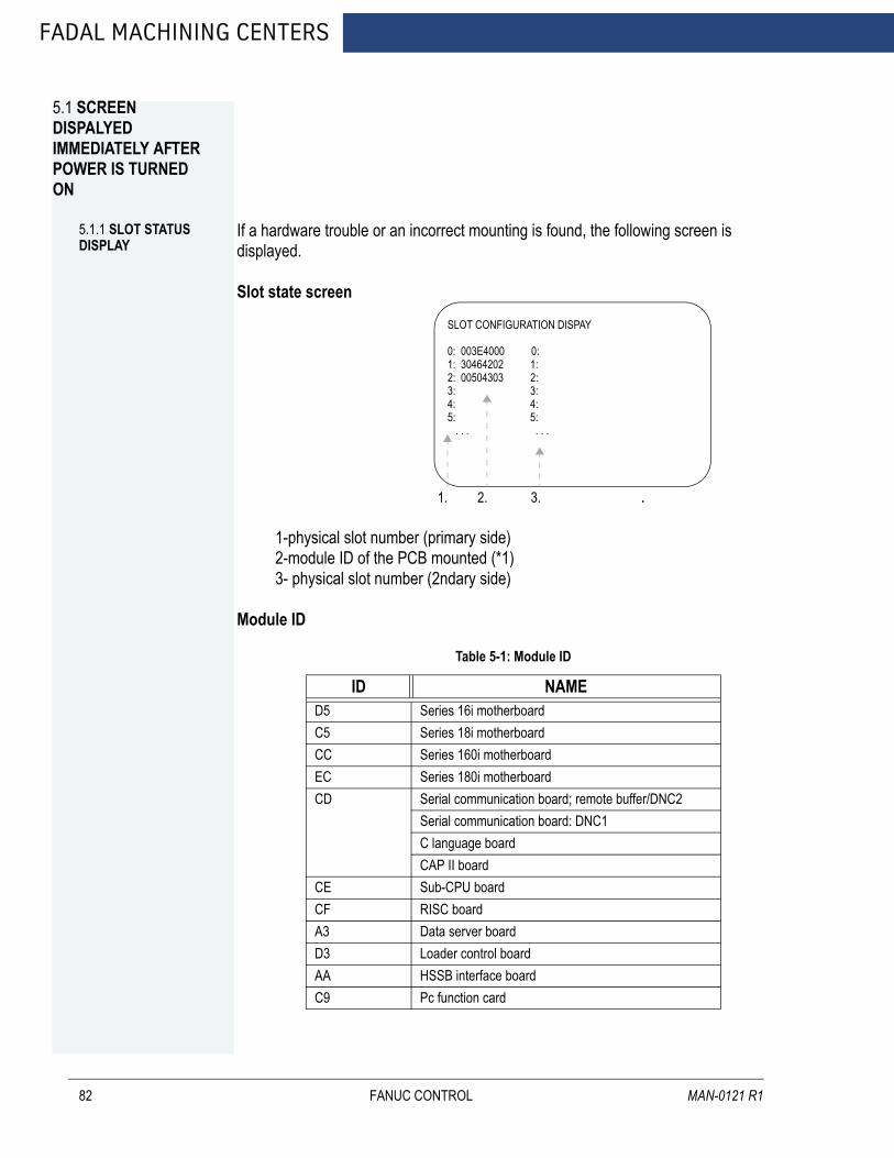
FADAL MACHINING CENTERS
5.1 SCREEN DISPALYED IMMEDIATELY AFTER POWER IS TURNED ON
82
5.1.1 SLOT STATUS DISPLAY
If a hardware trouble or an incorrect mounting is found, the following screen is displayed.
Slot state screen
1. 2. 3. .
1-physical slot number (primary side) 2-module ID of the PCB mounted (*1) 3- physical slot number (2ndary side)
Module ID
Table 5-1: Module ID
ID NAMED5 Series 16i motherboardC5 Series 18i motherboardCC Series 160i motherboardEC Series 180i motherboardCD Serial communication board; remote buffer/DNC2
Serial communication board: DNC1C language boardCAP II board
CE Sub-CPU boardCF RISC boardA3 Data server boardD3 Loader control boardAA HSSB interface boardC9 Pc function card
SLOT CONFIGURATION DISPAY
0: 003E4000 0:1: 30464202 1:2: 00504303 2:3: 3:4: 4:5: 5: . . . . . .
FANUC CONTROL MAN-0121 R1
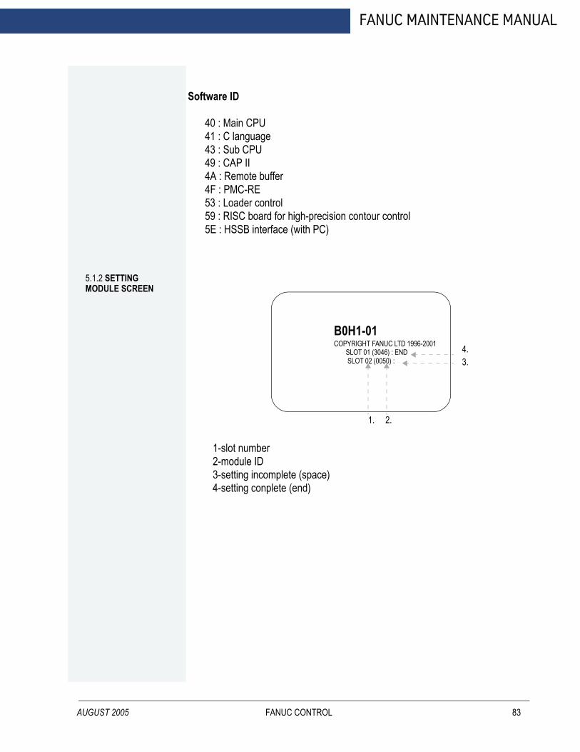
AUGUST 2005
FANUC MAINTENANCE MANUAL
Software ID
40 : Main CPU41 : C language43 : Sub CPU49 : CAP II4A : Remote buffer4F : PMC-RE53 : Loader control59 : RISC board for high-precision contour control5E : HSSB interface (with PC)
5.1.2 SETTING MODULE SCREEN
1-slot number 2-module ID 3-setting incomplete (space) 4-setting conplete (end)
B0H1-01COPYRIGHT FANUC LTD 1996-2001 SLOT 01 (3046) : END SLOT 02 (0050) :
1. 2.
4.3.
FANUC CONTROL 83
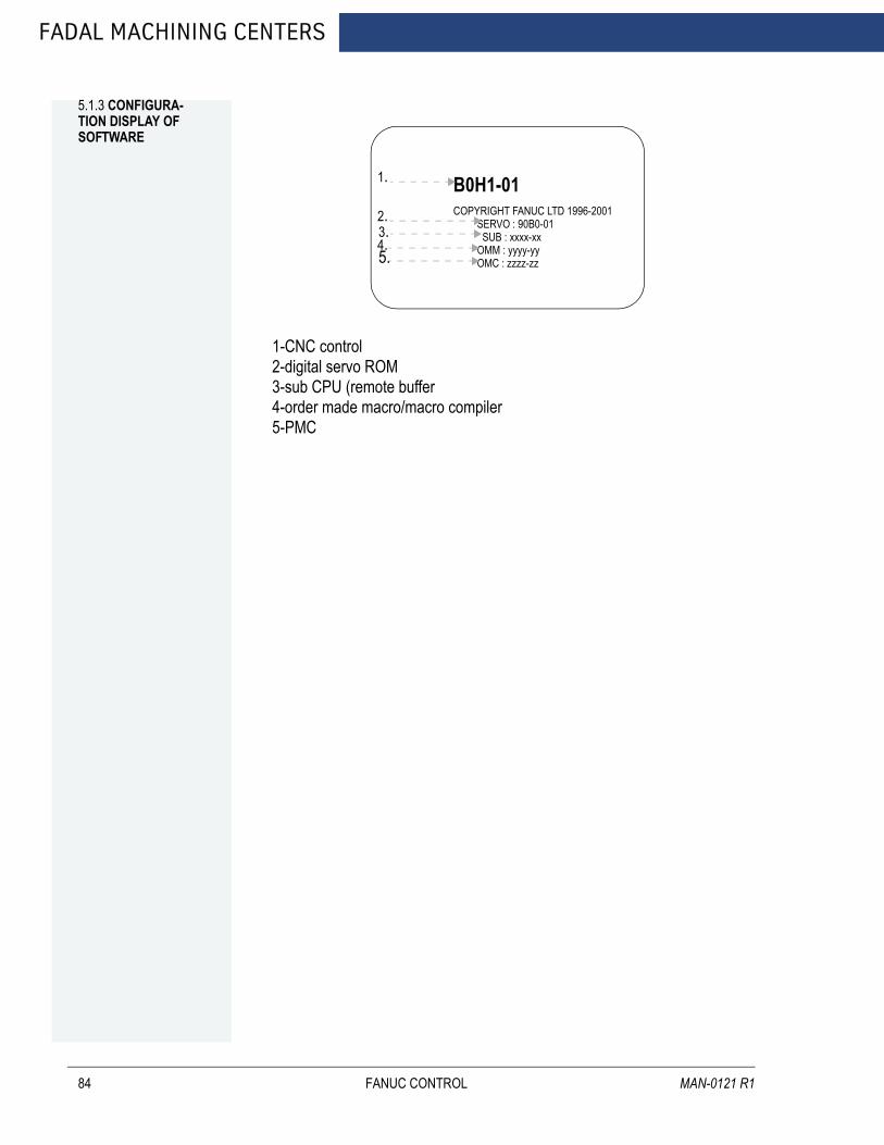
FADAL MACHINING CENTERS
5.1.3 CONFIGURA-TION DISPLAY OF SOFTWARE
84
1-CNC control 2-digital servo ROM 3-sub CPU (remote buffer 4-order made macro/macro compiler 5-PMC
B0H1-01COPYRIGHT FANUC LTD 1996-2001 SERVO : 90B0-01 SUB : xxxx-xx OMM : yyyy-yy OMC : zzzz-zz
1.
2.3.4.5.
FANUC CONTROL MAN-0121 R1
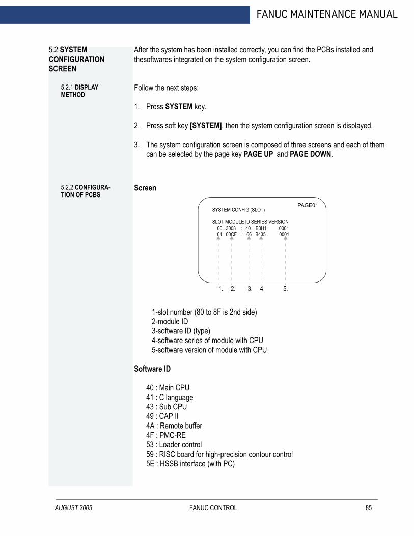
FANUC MAINTENANCE MANUAL
5.2 SYSTEM CONFIGURATION SCREEN
AUGUST 2005
After the system has been installed correctly, you can find the PCBs installed and thesoftwares integrated on the system configuration screen.
5.2.1 DISPLAY METHOD
Follow the next steps:
1. Press SYSTEM key.
2. Press soft key [SYSTEM], then the system configuration screen is displayed.
3. The system configuration screen is composed of three screens and each of them can be selected by the page key PAGE UP and PAGE DOWN.
5.2.2 CONFIGURA-TION OF PCBS
Screen
1-slot number (80 to 8F is 2nd side) 2-module ID 3-software ID (type) 4-software series of module with CPU 5-software version of module with CPU
Software ID
40 : Main CPU41 : C language43 : Sub CPU49 : CAP II4A : Remote buffer4F : PMC-RE53 : Loader control59 : RISC board for high-precision contour control5E : HSSB interface (with PC)
SYSTEM CONFIG (SLOT)
SLOT MODULE ID SERIES VERSION 00 3008 : 40 B0H1 0001 01 00CF : 66 B435 0001
PAGE01
1. 2. 3. 4. 5.
FANUC CONTROL 85
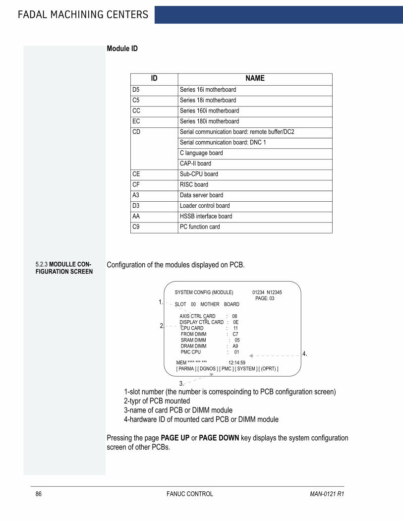
FADAL MACHINING CENTERS
86
Module ID
ID NAMED5 Series 16i motherboardC5 Series 18i motherboardCC Series 160i motherboardEC Series 180i motherboardCD Serial communication board: remote buffer/DC2
Serial communication board: DNC 1C language boardCAP-II board
CE Sub-CPU boardCF RISC boardA3 Data server boardD3 Loader control boardAA HSSB interface boardC9 PC function card
5.2.3 MODULLE CON-FIGURATION SCREEN
Configuration of the modules displayed on PCB.
1-slot number (the number is correspoinding to PCB configuration screen) 2-typr of PCB mounted 3-name of card PCB or DIMM module 4-hardware ID of mounted card PCB or DIMM module
Pressing the page PAGE UP or PAGE DOWN key displays the system configuration screen of other PCBs.
SYSTEM CONFIG (MODULE) 01234 N12345 PAGE: 03SLOT 00 MOTHER BOARD
AXIS CTRL CARD : 08 DISPLAY CTRL CARD : 0E CPU CARD : 11 FROM DIMM : C7 SRAM DIMM : 05 DRAM DIMM : A9 PMC CPU : 01
MEM **** *** *** 12:14:59[ PARMA ] [ DGNOS ] [ PMC ] [ SYSTEM ] [ (OPRT) ]
2.
1.
3.
4.
FANUC CONTROL MAN-0121 R1
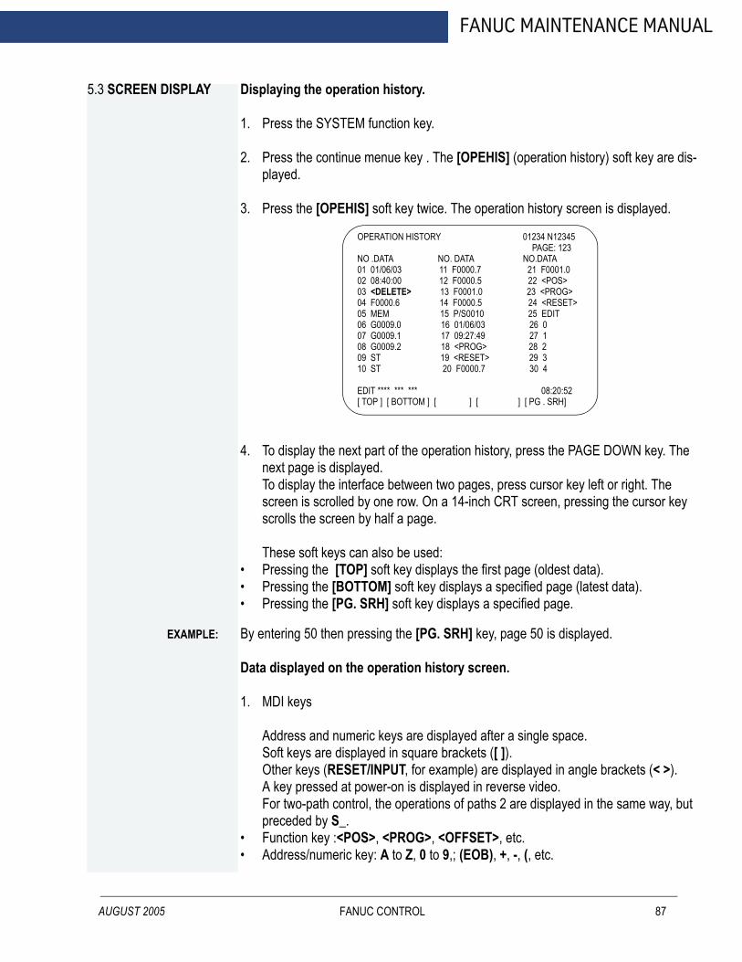
FANUC MAINTENANCE MANUAL
5.3 SCREEN DISPLAY
AUGUST 2005
Displaying the operation history.
1. Press the SYSTEM function key.
2. Press the continue menue key . The [OPEHIS] (operation history) soft key are dis-played.
3. Press the [OPEHIS] soft key twice. The operation history screen is displayed.
4. To display the next part of the operation history, press the PAGE DOWN key. The next page is displayed. To display the interface between two pages, press cursor key left or right. The screen is scrolled by one row. On a 14-inch CRT screen, pressing the cursor key scrolls the screen by half a page.
These soft keys can also be used:• Pressing the [TOP] soft key displays the first page (oldest data).• Pressing the [BOTTOM] soft key displays a specified page (latest data).• Pressing the [PG. SRH] soft key displays a specified page.
By entering 50 then pressing the [PG. SRH] key, page 50 is displayed.
OPERATION HISTORY 01234 N12345 PAGE: 123NO .DATA NO. DATA NO.DATA01 01/06/03 11 F0000.7 21 F0001.002 08:40:00 12 F0000.5 22 <POS>03 <DELETE> 13 F0001.0 23 <PROG>04 F0000.6 14 F0000.5 24 <RESET>05 MEM 15 P/S0010 25 EDIT06 G0009.0 16 01/06/03 26 007 G0009.1 17 09:27:49 27 108 G0009.2 18 <PROG> 28 209 ST 19 <RESET> 29 310 ST 20 F0000.7 30 4
EDIT **** *** *** 08:20:52[ TOP ] [ BOTTOM ] [ ] [ ] [ PG . SRH]
EXAMPLE:
Data displayed on the operation history screen.
1. MDI keys
Address and numeric keys are displayed after a single space.Soft keys are displayed in square brackets ([ ]). Other keys (RESET/INPUT, for example) are displayed in angle brackets (< >). A key pressed at power-on is displayed in reverse video.For two-path control, the operations of paths 2 are displayed in the same way, but preceded by S_.
• Function key :<POS>, <PROG>, <OFFSET>, etc.• Address/numeric key: A to Z, 0 to 9,; (EOB), +, -, (, etc.
FANUC CONTROL 87
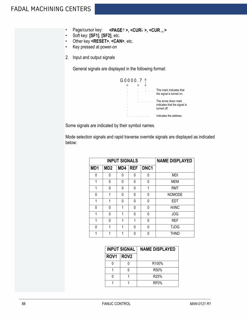
FADAL MACHINING CENTERS
88
• Page/cursor key: • Soft key: [SF1], [SF2], etc.• Other key <RESET>, <CAN>, etc.• Key pressed at power-on
2. Input and output signals
General signals are displayed in the following format:
Some signals are indicated by their symbol names.
Mode selection signals and rapid traverse override signals are displayed as indicated below:
INPUT SIGNALS NAME DISPLAYEDMD1 MD2 MD4 REF DNC1
0 0 0 0 0 MDI1 0 0 0 0 MEM1 0 0 0 1 RMT0 1 0 0 0 NOMODE1 1 0 0 0 EDT0 0 1 0 0 H/INC1 0 1 0 0 JOG1 0 1 1 0 REF0 1 1 0 0 TJOG1 1 1 0 0 THND
INPUT SIGNAL NAME DISPLAYEDROV1 ROV2
0 0 R100%1 0 R50%0 1 R25%1 1 RF0%
<PAGE >, <CUR >, <CUR >
G 0 0 0 0 . 7
This mark indicates thatthe signal is turned on.
The arrow down mark indicates that the signal is turned off.
Indicates the address.
FANUC CONTROL MAN-0121 R1
AUGUST 2005
FANUC MAINTENANCE MANUAL
3. NC alarms
NC akarms are displayed in reverse video.P/S alarms system alarms, and external alarms are displayed together with their numbers.For other types of alarms, only the alarm type is displayed. (No details are dis-played.)For two-path control, the operations of path 2 are displayed in the same way, but preceded by S_.
P/S0050, SV_ALM, S_APC_ALM
EXAMPLE:4. Time stamp (date and time)
The following time data (date and time) is recorded:
• Date and time of power-on• Date and time of power-off• Date and time when an NC alarm occurs• The clock time is recorded at predetermined intervals, together with each new cal-
endar day.
EXAMPLE:
01/01/20 ==== Year/Month/Day09:15:30 ==== Hour:Minute:Second
The clock time is recorded for a specified interval only when data is stored within that interval. If a system alarm is issued, the system alarm occurrence time is used for power-off display.5.3.1 INPUT SIGNAL OR OUTPUT SIGNAL TO BE RECORDED IN THE OPERATION HISTORY
1. Press the SYSTEM function key.
2. Press the continuous menu key. The [OPEHIS] (operation history) soft key is dis-played.
3. Press the [OPEHIS] soft key, then press the [SG-SEL] soft key. The operation his-tory sihnal selection screen is displayed.
FANUC CONTROL 89

FADAL MACHINING CENTERS
90
OP_HIS SIGNAL SELECT 01000 N02000
NO. ADDRESS SIGNAL01020304050607080910>
X0000 X0004 X0008 X0009 X0012 Y0000 Y0004 Y0007 Y0008 Y0010
00001000100000000000110000111000000011110100000000110000000111000001110000011100
NO. ADDRESS SIGNAL11121314151617181920
G0000 G0004 G0008 G0003 G0043
0000000100000011000001110000111101100000* * * * * * * * * * * * * * * * * * * * * * * * * * * * * * * * * * * * * * * *
EDIT * * * * * * * * * * 00:00:00[ OPEHIS ] [ SG-SEL ] [ ] [ ] [ (OPE) ]
FANUC CONTROL MAN-0121 R1

FANUC MAINTENANCE MANUAL
5.4 CNC STATE DISPLAY
AUGUST 2005
1. 2. 3. 4. 7. 8. 5.
- display example and explanation. -indicates the current status of the CNC.
MEM STRT MTN * * * 09:06:35
1. Mode selection status
MEM: Automatic operation (memory operation).MDI: Manual data input/MDI operation.EDIT: Program editing.RMT: Remote operaion. JOG: Jog feed.REF: Reference position return.INC: Incremental feed mode = step feed. HND: Manual handle feed mode.TJOG: Teaching in jog feed mode.THND: Teaching in handle feed mode.
2. Automatic operation status
STRT: Automatic operation has started (and program execution is under way). HOLD: Automatic operation has been suspended.STOP: Automatic operation has stopped.MSTR: The tool is returning or being repositioned when the tool retract and return function is executed.* * * * : Other staus (when the power is switched on, or automatic operation has ended).
3. Automatic operation status
MTN: Program-specified axis movement is under way.DWL: Program-specified dwell command (G04) is being executed.
ACTUAL POSITION (ABSOLUTE) O1000 N00010
XYZ
217. 940363. 233 0. 000
RUN TIMEACT.F
PART COUNT0H15M CYCLE TIME 0H 0M38S
5
3000MM/M S 0 T0000
MEM STRT MTN * * * 09:06:35[ ABS ] [ REL ] [ ] [ HNDL ] [ OPRT ]
FANUC CONTROL 91

FADAL MACHINING CENTERS
92
* * * : Other status
4. Auxiliary function status
FIN: The completion signal FIN for an auxiliary function is being awaited.* * * : Other status
5. Emergency stop and reset status (displayed at the location of items mentioned in (3) and (4)).
EMG: Emergency stop statusRESET: CNC reset status (The state in which the reset signal or the MDI RESET key remains active).
6. Alarm status
ALM: An alarm condition has been detectedBAT: The lithium battery (CNC back-up battert) voltage is low (the battery is to be replaced).
7. Clock display
Input: Data is being input.Output: Data is being output.SRCH: A data search is under way.EDIT: Editing such as insertion or modification is under way.LSK: Label skip enabled at data input (until valid information is read).PTRR: Retract or return/re-positioning is under way when the tool retrack and return function is used.HPCC: High-precision contour cotrol mode.AICC: AI contour control mode.AI NANO: AI nano contour control mode.AI HPCC: AI high-precision contour control mode.NANO HP: AI nano high=precision cotour control mode.AIAPC: AI advanced preview control mode.RVRS: Reversing based on the retrace function.RTRY: Re-advancing based on the retrace function.RVED: Reversing based on the retrace function has ended.Blank: Editing is not under way.
FANUC CONTROL MAN-0121 R1
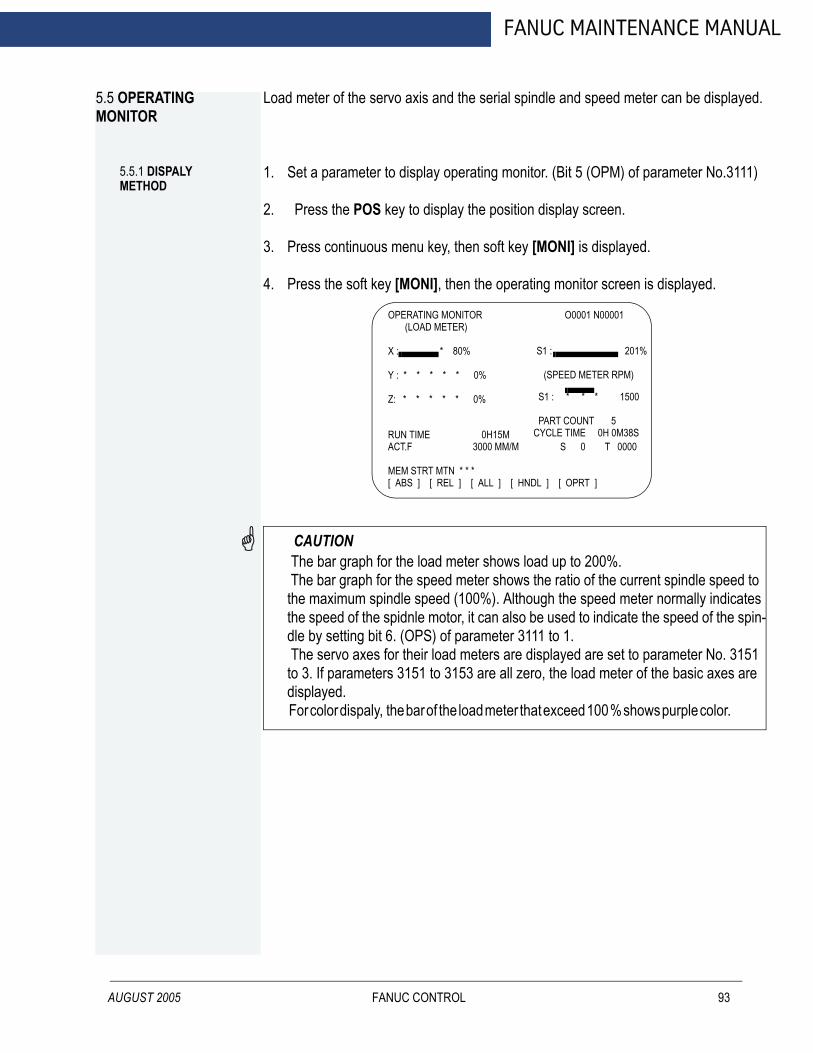
FANUC MAINTENANCE MANUAL
5.5 OPERATING MONITOR
AUGUST 2005
Load meter of the servo axis and the serial spindle and speed meter can be displayed.
5.5.1 DISPALY METHOD
1. Set a parameter to display operating monitor. (Bit 5 (OPM) of parameter No.3111)
2. Press the POS key to display the position display screen.
3. Press continuous menu key, then soft key [MONI] is displayed.
4. Press the soft key [MONI], then the operating monitor screen is displayed.
CAUTION
OPERATING MONITOR O0001 N00001 (LOAD METER)
X : * 80%
Y : * * * * * 0%
Z: * * * * * 0%
S1 : 201%
(SPEED METER RPM)
S1 : * * * 1500 PART COUNT 5 CYCLE TIME 0H 0M38S
RUN TIMEACT.F 3000 MM/M S 0 T 0000
0H15M
MEM STRT MTN * * *[ ABS ] [ REL ] [ ALL ] [ HNDL ] [ OPRT ]
The bar graph for the load meter shows load up to 200%. The bar graph for the speed meter shows the ratio of the current spindle speed to the maximum spindle speed (100%). Although the speed meter normally indicates the speed of the spidnle motor, it can also be used to indicate the speed of the spin-dle by setting bit 6. (OPS) of parameter 3111 to 1. The servo axes for their load meters are displayed are set to parameter No. 3151 to 3. If parameters 3151 to 3153 are all zero, the load meter of the basic axes are displayed. For color dispaly, the bar of the load meter that exceed 100 % shows purple color.FANUC CONTROL 93
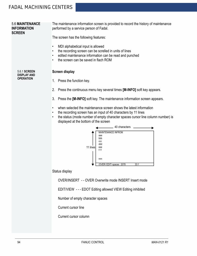
FADAL MACHINING CENTERS
5.6 MAINTENANCE INFORMATION SCREEN
94
The maintenance information screen is provided to record the history of maintenance performed by a service person of Fadal.
The screen has the following features:
• MDI alphabetical input is allowed• the recording screen can be screlled in units of lines• edited maintenance information can be read and punched• the screen can be saved in flach ROM
5.6.1 SCREEN DISPLAY AND OPERATION
Screen display
1. Press the function key.
2. Press the continuous menu key several times [M-INFO] soft key appears.
3. Press the [M-INFO] soft key. The maintenance information screen appears.
• when selected the maintenance screen shows the latest information• the recording screen has an input of 40 characters by 11 lines• the status (mode number of empty character spaces cursor line column number) is
displayed at the bottom of the screen
Status display
OVER/INSERT - - OVER Overwrite mode INSERT Insert mode
EDIT/VIEW - - - EDOT Editing allowed VIEW Editing inhibited
Number of empty character spaces
Current cursor line
Current cursor column
11 lines
40 charactersMAINTENANCE INFROMaaabbbcccdddeeef f f
nnn
/OVER/ EDIT/ spaces : 2078 33:1
FANUC CONTROL MAN-0121 R1

AUGUST 2005
FANUC MAINTENANCE MANUAL
Screen operation
The maintenance information screen has view mode and edit mode which are selected by pressing the [END] or [EDIT] soft key.
Initially view mode is selcted. To start editing select edit mode by pressing the ([OPRT)] and [EDIT] keys. When the editing is completed press the [END] key. Then select [STORE] or [IGNORE]. Unless [STORE] is selected the edited data will be lost at next power-up. To scroll the screen showing the recorded information press a cursor key or page key on the MDI screen.
The following keys are used for editing (character input) and viewing.
Operation tableMODE KEY DESCRIPTION
View Soft keys[EDIT][JUMP]
Allows editingDisplays the begining or the end
Cursor key Scrolls the screen up or downPage key Scrolls the screen up or down in units of whole screens
Edit Soft keys[END][ALLDEL]
[I/O][JUMP]
Ends editing. Select whether to store the edited dataClears all maintenance information. (This key is enabled when the MDC bit (bit 3 of parameter 3118) is set to 1)Reads or punches the maintenance informationMoves the cursor to the beginning or end
Cursor key Moves the cursor position up or downPage key Scrolls the screen up or down in units of whole screensAlphanumeric/special charac-ter key
Allowas alphabetical numeric or special characte input
INSERT key Select either insert mode or overwrite modeFunction key Deletes a single characterCAN key Deletes a single character before the cursor positionINPUT key Starts a new line
FANUC CONTROL 95

FADAL MACHINING CENTERS
96
Operation of the soft keys
(1) View mode
(2) Edit mode
(3) Edit saving
(4) I/O
(5) Jump
(6) Execution
(2) (5)
Edit Jump
END I/O ALLDEL Jump
Maintenance
IGNORE CANCEL
READ PUNCH CANCEL
Begining END CANCEL
EXEC CANCEL
(1) (1)
(3) (4) (5) (6)
(2)
(6) (6) (2)
(1) (2) (1) (2) (1) (2)
(2) (2)
5.6.2 MAINTENANCE INFORMATION INPUT/OUTPUT
The maintenance can be read and punched:
When the maintenance information is input from or output to a memory card a file name MAINTINFDAT is used.
1. Format
Data% %
FANUC CONTROL MAN-0121 R1

AUGUST 2005
FANUC MAINTENANCE MANUAL
2. Reading
When a MAINTINFDAT file generated in the format shown above is read the data is added at the end of the exisiting maintenance information.
NOTE A TAB code is converted to one to four blanks depending on the input position. Control codes (00H to 1FH) except TAB and LF are discarded in reading. %% cannot be input.
FANUC CONTROL 97

FADAL MACHINING CENTERS
5.7 POWER MOTION MANAGER
98
When the Power Motion series is used as an additional axis (slave) of the CNC the power motion manager allows the slave data to be displayed and set by the CNC.
The power motion manager enables the following display and setting:
1. Current position display (absolute/machine coordinates)
2. Parameter display and setting
3. Diagnosis display
4. System configuration screen display
5. Alarm display
The Power Motion series that can be used as the slave is a β amplifier with I/O Link.
5.7.1 PARAMETER
[Data type] Bit
SLV - - When the power motion manager is selected the screen shows the data of:
0 A single slave1 Up to four slaves by dividing the screen into four segments
MD1, MD2 - -The slave parameters are input from and output to the following devices:
The parameters are input or output in the program format no matter which I/o device is selected.
PMN - - The power motion manager finction is:
0 Enabled1 Disabled (Communication with the slave is not performed)
MD2 MD1 I/O device0 0 Part program storage0 1 Memory card
960 2CH ASG SLPWE PMN MD2 MD1 SLV#7 #6 #5 #4 #3 #2 #1 #0
FANUC CONTROL MAN-0121 R1

AUGUST 2005
FANUC MAINTENANCE MANUAL
SLPWE - - Settings of slave parameters
0 Can be made by Power mate CNC manager regardless of the PWE setting1 Are made according to the PWE setting
ASG - - Whether or not the number of bytes allocated to the input/output destination of the β amplifier with I/O links is 16
0 Is checked1 Is not checked
2CH - - Power mate CNC manager
0 Communicates with channel 21 Communicates with channel 1
5.7.2 SCREEN DISPLAY
1. Press the function key.
2. Press the continuous menu key several times. The [PMM] soft key appears.
3. Press the [PMM] soft key. The system configuration screen which is the initial screen of the power motion manager appears. The screen has the following soft keys (function selection soft keys)
The currently active soft key is displayed in reverse video. Pressing a soft key enables the corresponding function as indicated below:
POS Current position displaySYSTEM System informationMSG Alarm list
To select another function after one of the functions listed above is selected press the return menu key several times until the soft keys are displayed as shown above. Then select the desired function.
4. To terminate the power motion manager repeatedly press the return menu key until the function selection keys are displayed as shown above. Then press the return menu key once more. The soft keys of the CNC system appear and the power motion manager terminates. The system configuration screen of this function is displayed as the termination screen.
[ POS ] [ ] [ ] [ SYSTEM [ MSG ]
FANUC CONTROL 99

FADAL MACHINING CENTERS
100
Alternative termination method is to select another function while this function is enables. To do this press an MDI funciton key (POS, PROG, ...)
NOTE After another screen is displayed by pressing a function key pressing the function key restores the initial status of this function. That is the soft keys shown above are restored. The data that was being input is canceled.
System configuration
This screen displays the system software information of the slave. The screen is displayed first when the power motion manager function is selected. This screen is automatically displayed also at the termination of hte function.
1. Press the [SYSTEM] function selection soft key. The following soft keys are dis-played together with the screen displayed when SYSTEM was last selected. The currenctly active soft key is displayed in reverse video.
2. Press the [SYSTEM] soft key again. The system configuration screen appears.
While this screen is displayed, the [SYSTEM] soft key is left displayed is reverse video.
Parameter screen
The parameters necessary for the functions of the slave must be specified in advance.
1. Press [SYSTEM] function selection soft key. The following soft keys appear:
[ PARAM ] [DGNOS ] [ ] [ SYSTEM ] [ ]
POWER MOTION MANAGERSYSTEM CONFIGURATION
βSYSTEM <SERIES/ VERSION> 88 A1 011. GROUP0 /β
[ PARAM ] [ DGNOS ] [ ] [ SYSTEM ] [ ]
[ PARAM ] [DGNOS ] [ ] [ SYSTEM] [ ]
FANUC CONTROL MAN-0121 R1
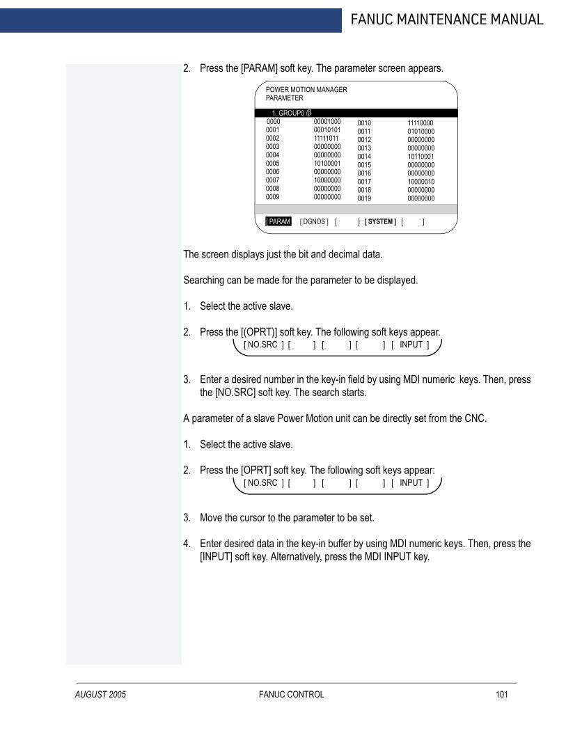
AUGUST 2005
FANUC MAINTENANCE MANUAL
2. Press the [PARAM] soft key. The parameter screen appears.
The screen displays just the bit and decimal data.
Searching can be made for the parameter to be displayed.
1. Select the active slave.
2. Press the [(OPRT)] soft key. The following soft keys appear.
3. Enter a desired number in the key-in field by using MDI numeric keys. Then, press the [NO.SRC] soft key. The search starts.
A parameter of a slave Power Motion unit can be directly set from the CNC.
1. Select the active slave.
2. Press the [OPRT] soft key. The following soft keys appear:
3. Move the cursor to the parameter to be set.
4. Enter desired data in the key-in buffer by using MDI numeric keys. Then, press the [INPUT] soft key. Alternatively, press the MDI INPUT key.
POWER MOTION MANAGERPARAMETER
1. GROUP0 /β0000 0001
00020003000400050006000700080009
00001000000101011111101100000000000000001010000100000000100000000000000000000000
0010001100120013001400150016001700180019
11110000010100000000000000000000101100010000000000000000100000100000000000000000
[ PARAM ] [ DGNOS ] [ ] [ SYSTEM ] [ ]
[ NO.SRC ] [ ] [ ] [ ] [ INPUT ]
[ NO.SRC ] [ ] [ ] [ ] [ INPUT ]
FANUC CONTROL 101
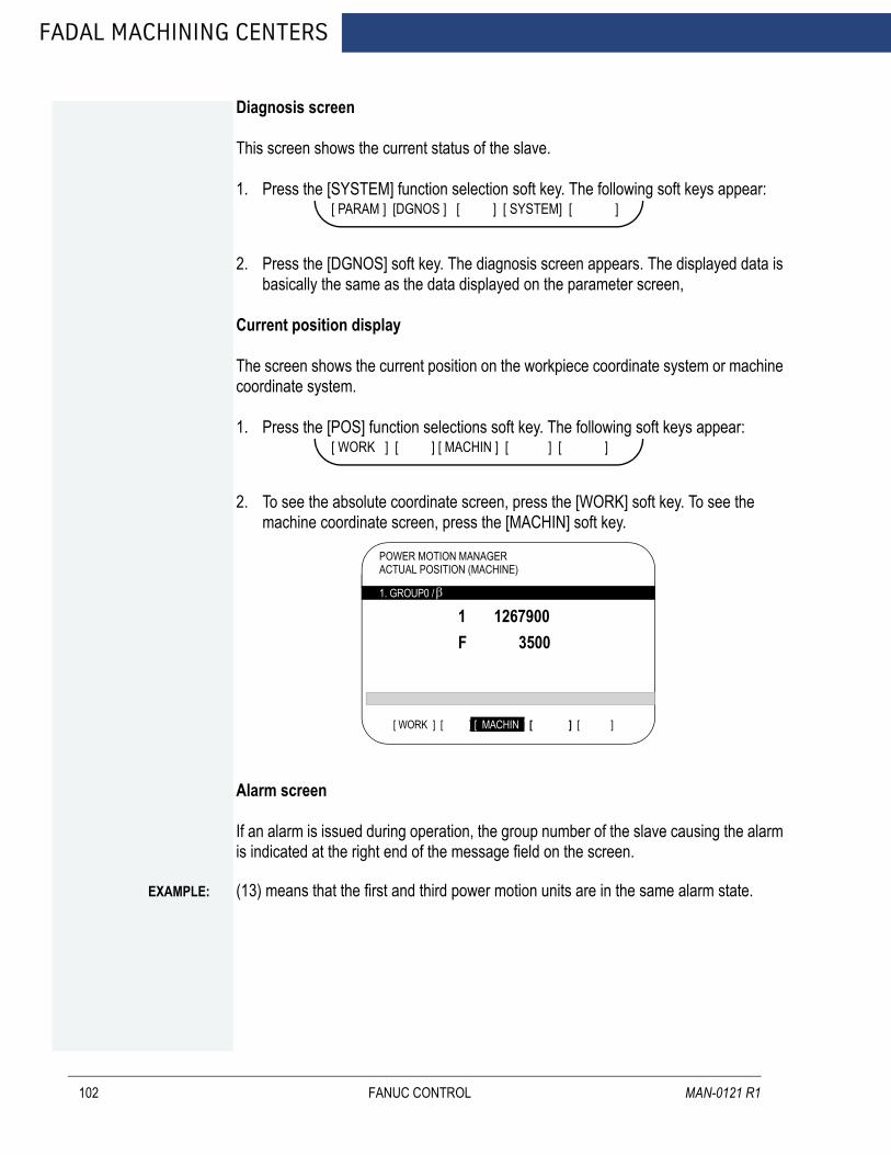
FADAL MACHINING CENTERS
102
Diagnosis screen
This screen shows the current status of the slave.
1. Press the [SYSTEM] function selection soft key. The following soft keys appear:
2. Press the [DGNOS] soft key. The diagnosis screen appears. The displayed data is basically the same as the data displayed on the parameter screen,
Current position display
The screen shows the current position on the workpiece coordinate system or machine coordinate system.
1. Press the [POS] function selections soft key. The following soft keys appear:
2. To see the absolute coordinate screen, press the [WORK] soft key. To see the machine coordinate screen, press the [MACHIN] soft key.
Alarm screen
If an alarm is issued during operation, the group number of the slave causing the alarm is indicated at the right end of the message field on the screen.
[ PARAM ] [DGNOS ] [ ] [ SYSTEM] [ ]
[ WORK ] [ ] [ MACHIN ] [ ] [ ]
POWER MOTION MANAGERACTUAL POSITION (MACHINE)
β 1. GROUP0 /β
[ WORK ] [ ] [ MACHIN ] [ ] [ ]
1 1267900F 3500
EXAMPLE:
(13) means that the first and third power motion units are in the same alarm state.FANUC CONTROL MAN-0121 R1

AUGUST 2005
FANUC MAINTENANCE MANUAL
1. Press the [MSG] function selection soft key. just the error code is displayed on the screen.
Up to forty (40) codes can be displayed on the screen.
Operating the active slave
The active slave is subjected to the ZOOM function, which will be described later, and parameter overwrite. The title of the active salve is displayed in a color different from the display color of the other slave titles.
The active slave can be selected by pressing the [NEXT] or [BACK] soft key, which is displayed after the continuius menu key is pressed several times.
NEXT: Displays the screen of the Power Motion unit connected after the currently active slave. The equipment other than the Power Motion unit is ignored.
BACK: Displays the screen of the Power Motion unit connected before the cur rently active slave.
Single-slave display/four-slave display
Whether the screen displays the data of njust a single unit or of four units in four segments is spcified in the SLV bit (bit 0 of parameter 960)
To switch the four-slave display to the single-slave display, press the [ZOOM] soft key, which is displayed after the continuous menu key is pressed several times. The single-slave display shows the data of the active slave. To switch the single-slave display to the four-slave display showing the data of four slave including the active slave, press the [ZOOM] key.
When five or more slaves are connected, the four-slave display has two or more pages. to see the slave data that is not displayed on the current page, press soft key [NEXT].
POWER MOTION MANAGERALARM
β 442 210 232
1. GROUP0 /β
[ POS ] [ ] [ ] [ ] [ MSG ]
FANUC CONTROL 103

FADAL MACHINING CENTERS
104
The figure above shows a sample four-slave display screen on a display unit with twelve soft keys. A unit with seven soft keys can also display the four-slave display screen.
The figure above shows a sample single-slave display screen on a display unit with seven soft keys. A unit with twelve soft keys can also display the single-slave display screen.
Guidance message
While the following soft keys are being displayed a guidance message is displayed in the message field.
β
1.GROUP0 /
3. GROUP2 /
2. GROUP1 /
4. GROUP3 /
POWER MOTION MANAGER/SYSTEM CONFIGURATION O12345678 N12345
SYSTEM ****--##
SYSTEM 88A1--01
SYSTEM 88A--01
SYSTEM ****--##SERVO ****--##
β
β β
β
SYSTEM DGNOS PARAM (OPRT)
POWER MOTION MANAGER O12345678 N12345SYSTEM CONFIGURATION
β
1. GROUP0 /β
[ POS ] [ DGNOS ] [ ] [ SYSTEM ] [ MSG ]
SYSTEM <SERIES/VERSION> 88A1--01
[ WORK ] [ ] [ MACHIN ] [ ] [ ]
FANUC CONTROL MAN-0121 R1

AUGUST 2005
FANUC MAINTENANCE MANUAL
When the soft keys are displayed as shown above SELECT ACTIVE SLAVE is displayed.
Key-in field
When the [(OPRT)] soft key is pressed the message line may turn into a key-in field as require. The numeric data input by using DMI keys is displayed after the prompt (>).
[ PARAM ] [DGNOS ] [ ] [ SYSTEM] [ (OPRT)
[ POS ] [ ] [ ] [ SYSTEM ] [ MSG ]
[ ] [ ]
5.7.3 PARAMETER INPUT/OUTPUT
Saving parameters
Parameters can be saved in CNC memory or a memory card as a data file of program format. Specify the first digit of the registration program number in parameter 8760.programs with predetermined numbers are created for individual slaves. When the parameters are saved in CNC memory a program having the speicified program number is created. When the parameters are saved in a memory card a file is created to which the file name consists of the specified program number and an extension PMM.
EXAMPLE:
When parameter 8760 is set to 8000.The program number for group n is 8000+n*10.
The group number n is indicated in the title area of each slave.
In case that the parameters are saved in a memory card if the specified program number already exists on memory card the corresponding program is overwritten with new data.
Specify a desired input device in the MD1 and MD2 bits (bits 1 and 2 of parameter 960). Connect a memory card. Alternatively check the free area of CNC memory. Then follow the steps given below:
1. Select the active slave.
2. Press the [(OPRT)] soft key.
3. Press the continuous menu key.
FANUC CONTROL 105

FADAL MACHINING CENTERS
106
4. Press the [READ] soft key.
5. Press the [EXEC] soft key.
During input INPUT blinks in the message field.
Writting parameters
The data file of parameters saved in CNC memory or a memory card as a program is written into the slave determined by the program number. The program number and memory device are determined as described in Saving parameters.
1. Press the active slave.
2. Press the [(OPRT)] soft key.
3. Press the next-menu key.
4. Press the [PUNCH] soft key.
5. Press the [EXEC] soft key.
During input INPUT blinks in the message field.
The screen cannot be changed to another screen during parameter input/output.
When the RESET key is pressed or when an alarm status is detected in communication the input/output stops.
FANUC CONTROL MAN-0121 R1

FANUC MAINTENANCE MANUAL
5.8 PERIODIC MAINTENANCE SCREENS
AUGUST 2005
Using the periodic maintenance screens makes it easy to manage consumable (such as LCD unit backlight and backup battery) that are to be replaced periodically.
5.8.1 OVERVIEW
The following configurationThe following periodic maintenance screens are available.
• Status screen. Displays item names remaining service time countdown status and lets you specify item names.
• Setting screen. Lets you specify service life remaining service time and count type (countdown method).
• Machine system menu screen. Displays the names of registered consumable used in the NC.
Procedure
To use this function follow the steps below:
1. Select a number for registration (using the cursor key on the status screen)
2. Specify an item name
- Selecting a name from a menu screen (machine or NC system menu screen)- Entering a name to the status screen directly form the MDI. Using the
machine system menu screen requires that item names be registeredpreviously.
3. Specify the service life remaining service time and count type for a target item.
Once they are specified the remaining service time can be checked on the status screen.
5.8.2 SCREEN DISPLAY AND SETTING
Follow the next steps:
1. Press the function key.
2. Press the continuous menu key several times. Soft key [MAINTE] appears.
3. Press soft key [MAINTE]. A periodic maintenance screen appears .
There are two periodic maintenance screens status and setting screens. Either screen can be selected using soft key [CHANGE].
FANUC CONTROL 107

FADAL MACHINING CENTERS
5.8.3 STATUS SCREEN DISPLAY AND SET-TING
108
Up to 10 consumable items can be registered for management. Their remaining service time and count status are displayed on the status screen.
Item name
The name of an item to be subjected to periodic maintenance is specified under ITEM name.
Two methods can be used to specify item names. The first method uses the menu screen and the second the MDI keypad.
1. Method of using the menu screen.
- place the cursor on the target item name and press soft key [ENTRY]. A menuscreen appears. The menu screen is either the machine or NC systemsystem.
- press soft key [MACIN] or [NC]. A machine system menu appears. It holds thenames of consumables typical to the machine system or NC system.
- place the cursor on a registered item name and press soft key [SELECT]then soft key [EXEC]. The status screen appears again enbling theselected item to be set up.
- press soft key [CAN]. The previous soft key displays appear again.- press soft key [MAINTE. The status screen appears again.
Using the machine system menu screen requires that item names be registered on the screen previously.
This can be done using two methods (a) and (b).
PERIODICAL MAINTENANCE O0001 N12345 (STATUS)
ITEM NAME REMAIN* 01@02 03@04 05 06 07 08 09 10
BATTERY FOR CONTROLLERBATTERY FOR PUSLECODER 5000HFAN MOTORLCD BACK LIGHT
0H
10000H 720H
>_EDIT * * * * * * * * * * * * * * * [ ] [ MAINTE ] [ ] [ ] [ (OPRT) ]
[ CHANGE ] [ ENTRY ] [ CLEAR ] [+INPUT ] [ INPUT ]
[ CHANE ] [ ENTRY ] [ CLEAR ] [ CAN ] [ EXEC ]
FANUC CONTROL MAN-0121 R1

AUGUST 2005
FANUC MAINTENANCE MANUAL
(a). Program-based registration. Executing a program in the following format enables item names to be registered on the machine system menu screen.
(b). MDI keypad-based registration. An item name can be registered on the machine system menu screen by
first entering it in the following format then pressing soft key [INPUT]. Pressing soft key [+INPUT] adds the item name to the list of previously
registered item names.
The two-byte characters shall comply eith the FANUC code.When entering a two-byte character sandwich it withan * pair.The item name can consist of up to 24 alphanumeric characters (if no two-byte
character is included) or 12 two-byte characters (if no alphanumericcharacter is included).
To register LCD backlight enter
G10 L61 Px [n]
x Registration number
n Item name [Alphanumeric characters two-byte characters alphanumeric characters].
Alphanumeric characters two-bytes characters alphanumeric characters.
EXAMPLE:
>LCD*110E10F410CC114010B610FE_
NOTE * cannot be used in item names because it is used as control code [ ] (or) also cannot be used in it names.
To erase the registered data for an item place the cursor on the target item name and press soft key [CLEAR] then soft key [EXEC].
FANUC CONTROL 109
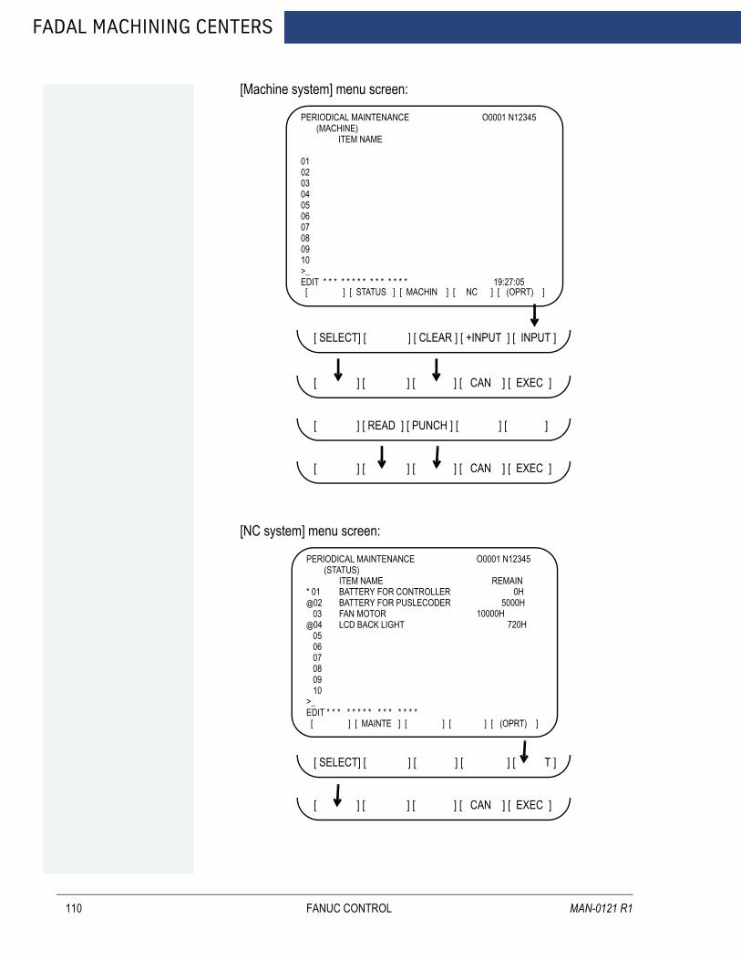
FADAL MACHINING CENTERS
110
[Machine system] menu screen:
[NC system] menu screen:
PERIODICAL MAINTENANCE O0001 N12345 (MACHINE) ITEM NAME
01020304050607080910>_ EDIT * * * * * * * * * * * * * * * 19:27:05 [ ] [ STATUS ] [ MACHIN ] [ NC ] [ (OPRT) ]
[ SELECT] [ ENTRY ] [ CLEAR ] [ +INPUT ] [ INPUT ]
[ CHANE ] [ ENTRY ] [ CLEAR ] [ CAN ] [ EXEC ]
[ CHANE ] [ READ ] [ PUNCH ] [ CAN ] [ EXEC ]
[ CHANE ] [ ENTRY ] [ CLEAR ] [ CAN ] [ EXEC ]
PERIODICAL MAINTENANCE O0001 N12345 (STATUS)
ITEM NAME REMAIN* 01@02 03@04 05 06 07 08 09 10
BATTERY FOR CONTROLLERBATTERY FOR PUSLECODER 5000HFAN MOTORLCD BACK LIGHT
0H
10000H 720H
>_EDIT * * * * * * * * * * * * * * * [ ] [ MAINTE ] [ ] [ ] [ (OPRT) ]
[ SELECT] [ ENTRY ] [ CLEAR ] [ +INPUT ] [ INPUT ]
[ CHANE ] [ ENTRY ] [ CLEAR ] [ CAN ] [ EXEC ]
FANUC CONTROL MAN-0121 R1

AUGUST 2005
FANUC MAINTENANCE MANUAL
NOTE On the CNC system screen no item name can be registered erased input or output.
2. MDI keypad-based setting.
An item name can be registered on the status screen by first entering it in the following format using keys then pressing soft key [INPUT]. Pressing soft key [+INPUT] adds the item name to the list of previously registered item names.
The two-bytes characters shall comply with the FANUC code.When entering a two-byte character using keys sandwich it with an * pair.The item name can consist of up to 24 alphanumeric characters (of no two-byte character is included) or 12 two-byte characters (if no alphanumeric character is included)
To register LCD backlight enter
Alphanumeric characters two-bytes characters alphanumeric characters.
EXAMPLE:
>LCD*110E10F410CC114010B610FE_
NOTE * cannot be used in item names because it is used as control code [ ] (or) also cannot be used in it names.
To erase the registered data for an item place the cursor on the target item nam press soft key [CLEAR] then [EXEC].
When an item name is deleted the related service life remaining service time and count type are also deleted.
3. Remaining service time.
The remaining service time of an item (the time allowed before the item is replaced) is obtained by count-down and displayed under remaining service time. When the remaining service time decreases to a specified percentage (specified in parameter No 8911) of the service life or lower it is displayed in red.Count-down continues even after the rservice life has expired.
NOTE Setting is impossible on the status screen. it should be done on the setting screen.
FANUC CONTROL 111

FADAL MACHINING CENTERS
112
4. Count status.
The count status is displayed at the left of the corresponding item number as listed below:
DISPLAY COUNT STATUSBlank Count suspended
@ Count inder wayThe service life has expired
FANUC CONTROL MAN-0121 R1

FANUC MAINTENANCE MANUAL
5.9 LANGUAGE SETUP
AUGUST 2005
1. Change the language setting in the macro variable table.
- Press [OFFSET/SETTING] key on the MDI panel.- Press once or twice on the LCD screen until MACRO soft key comes out.- Press [MACRO] soft key on the LCD screen.- Input “598” on the MDI panel.- Press NO.SRH on the LCD screen, the variable No. 598 will be displayed on the LCD screen.- Iput “VALUE” number (value number depends on the language, see table above) from the MDI panel.- Press [INPUT] from the MDI panel.
2. Run the production program P8820 to enable the ENGLICH language option.
- Press [EDIT] key to select edit mode.- Press [PROG] key on the MDI panel.- Press [DIR] soft key on the LCD screen.- Input O8820.- Press [INPUT] key on the MDI panel.- Press [O.SRH] soft key on the LCD screen, make sure that program comes out on the screen.- Press [AUTO] key on the machine pendant- Press [DOOR OVR] key on the machine pendant until the door override is enabled.- Press [CYCLE START] key on the machine pendant.
3. Cycle the CNC power.
MACRO VARIABLE
#598
VALUE LANGUAGE0 English1 Japanese2 Germany3 French4 Chinese5 Italian6 Korea7 Spanish8 Dutch9 Portuguese
FANUC CONTROL 113

FADAL MACHINING CENTERS
114
4. Check the following screen on the CNC. If screen displays with the right language, the software insatallation is successful. Otherwise, repeat steps above all over again.
Follow these step to setup any language.
EXAMPLE:
ENGLISHJAPANESE
FANUC CONTROL MAN-0121 R1
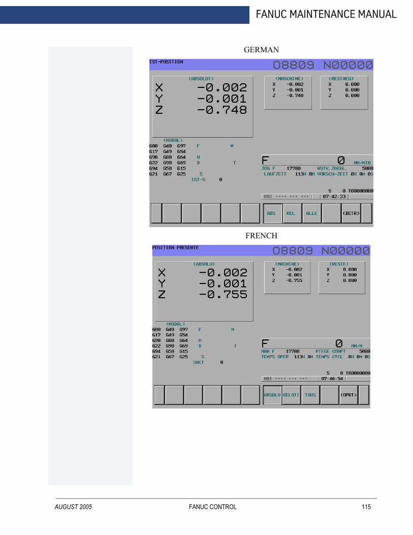
AUGUST 2005
FANUC MAINTENANCE MANUAL
GERMAN
FRENCH
FANUC CONTROL 115
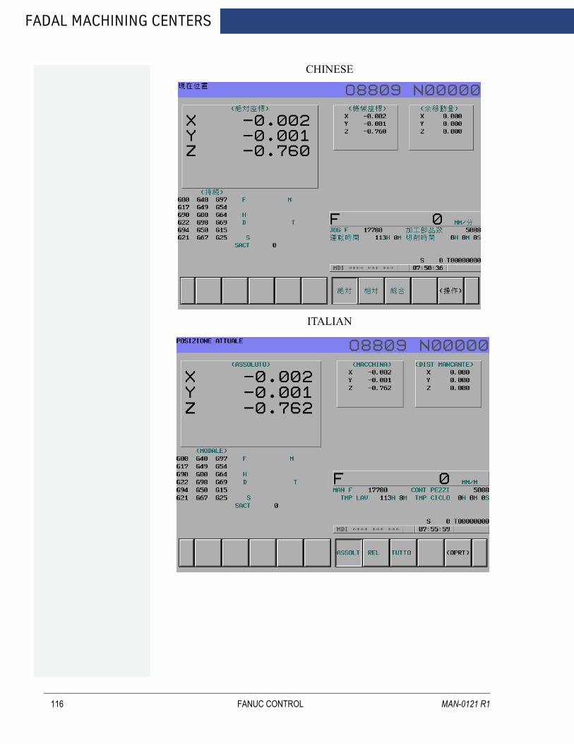
FADAL MACHINING CENTERS
116
CHINESE
ITALIAN
FANUC CONTROL MAN-0121 R1
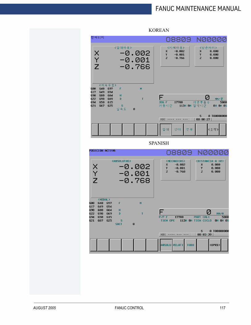
AUGUST 2005
FANUC MAINTENANCE MANUAL
KOREAN
SPANISH
FANUC CONTROL 117

FADAL MACHINING CENTERS
118
DUTCH
PORTUGUESE
FANUC CONTROL MAN-0121 R1

FANUC MAINTENANCE MANUAL
5.10 FINAL FILES BACKUP PROCEDURE
AUGUST 2005
Follow these steps:
I STEP:
Prepare operation
1. Smoothly put the COMPACT FLASH CARD inside the M-CARD slot of LCD.
2. Press EDIT PB. to change edit mode.
3. Press SYSTEM on the MDI panel until parameter screen comes out.
4. Press “+” twice using the soft key until ALL IO displays below the LCD.
5. Press ALL IO.
Backup the parameter
6. Press “<“ to return to the previous page.
7. Press PARAMETER.
8. Press OPRT.
9. Press PUNCH.
10. Press EXEC.
Backup the MACRO
11. Press “<“ to return to the previous page.
12. Press “+” to the next page.
13. Press MACRO
14. Press OPRT
15. Press PUNCH
16. Press EXEC
Backup the PITCH
17. Press “<“ to return to the previous page.
FANUC CONTROL 119

FADAL MACHINING CENTERS
120
18. Press PITCH.
19. Press OPRT.
20. Press PUNCH.
21. Press EXEC.
II STEP:
Backup the PLC software
1. Put the flash card into the slot on the LCD.
2. Press EDIT PB. to change edit mode.
3. Press SYSTEM on the MDI panel until parameter screen comes out.
4. Press PMC soft key.
5. Press I/O
6. Select the page as following (move the cursor, and use key to select the correct data type);
M-cardWriteLadderPMC-SB.000
7. Press EXEC.
Backup the PLC parameter
8. Move the cursor to the DATA TYPE.
9. Press PARAM soft key on the LCD.
10. Select the page as following;
M-cardWritePARAMPMC-SB.PRM
11. Press EXEC.
FANUC CONTROL MAN-0121 R1

AUGUST 2005
FANUC MAINTENANCE MANUAL
III STEP:
Sram backup procedure
1. Power of the machine.
2. Put the flash card into the slot.
3. Press the most right side two soft key on the LCD screen and hold.
4. Wait until the CNC system screen comes out.
5. Wait until the CNC system screen displays.
6. Press the DOWN soft key to move the cursor to the item 5 (highlighted).
System data backup
7. Press SELECT soft key will display two choices
“1. SRAM BACKUP (CNC -----Flash Card)”“2.. .......................................................”
8. Make sure the cursor is in the first line.
9. Press SELECT soft key and you will be asked “Backup SRAM Data OK?”
10. Select “YES” to continue (or “NO” to return to the previous menu).
11. Wait a few seconds. The screen will display complete information.
12. Press SELECT soft key.
13. Press DOWN soft key until the cursor moves to item : END.
14. Press SELECT.
15. Press DOWN soft key until the cursor moves to item : END.
16. Press SELECT.
17. Press “YES”.
18. End, the CNC system will boot up..
FANUC CONTROL 121

FADAL MACHINING CENTERS
122
FANUC CONTROL MAN-0121 R1
FANUC MAINTENANCE MANUAL
AUGUST 2005
6.0 OPTIONS SETUP
OPTIONS SETUP 123
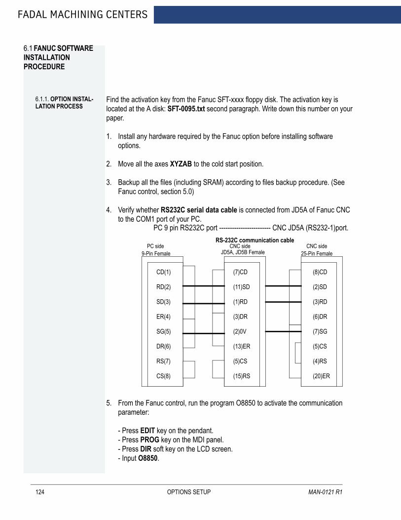
FADAL MACHINING CENTERS
6.1 FANUC SOFTWARE INSTALLATION PROCEDURE
124
6.1.1. OPTION INSTAL-LATION PROCESS
Find the activation key from the Fanuc SFT-xxxx floppy disk. The activation key is located at the A disk: SFT-0095.txt second paragraph. Write down this number on your paper.
1. Install any hardware required by the Fanuc option before installing software options.
2. Move all the axes XYZAB to the cold start position.
3. Backup all the files (including SRAM) according to files backup procedure. (See Fanuc control, section 5.0)
4. Verify whether RS232C serial data cable is connected from JD5A of Fanuc CNC to the COM1 port of your PC.
5. From the Fanuc control, run the program O8850 to activate the communication parameter:
- Press EDIT key on the pendant.- Press PROG key on the MDI panel.- Press DIR soft key on the LCD screen.- Input O8850.
PC 9 pin RS232C port ------------------------ CNC JD5A (RS232-1)port.
CD(1)
RD(2)
SD(3)
ER(4)
SG(5)
DR(6)
RS(7)
CS(8)
(7)CD (11)SD
(1)RD
(3)DR
(2)0V
(13)ER
(5)CS
(15)RS
(8)CD
(2)SD
(3)RD
(6)DR
(7)SG
(5)CS
(4)RS
(20)ER
PC side9-Pin Female
RS-232C communication cable CNC side
JD5A, JD5B Female CNC side25-Pin Female
OPTIONS SETUP MAN-0121 R1
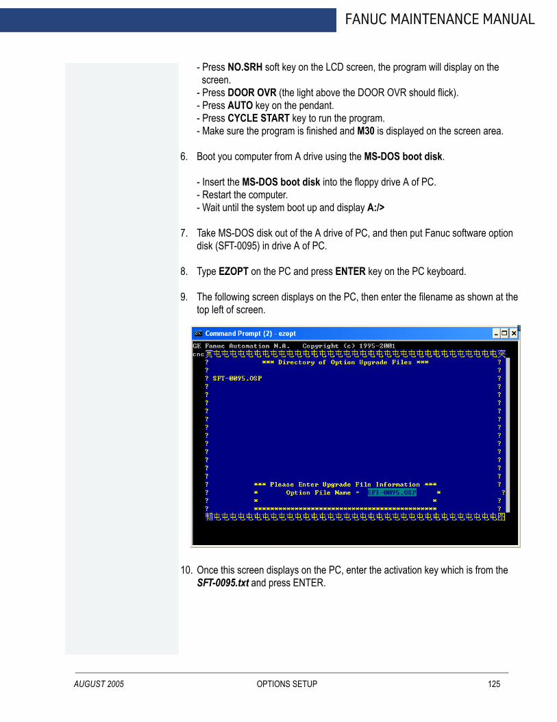
AUGUST 2005
FANUC MAINTENANCE MANUAL
- Press NO.SRH soft key on the LCD screen, the program will display on the screen.- Press DOOR OVR (the light above the DOOR OVR should flick).- Press AUTO key on the pendant.- Press CYCLE START key to run the program.- Make sure the program is finished and M30 is displayed on the screen area.
6. Boot you computer from A drive using the MS-DOS boot disk.
- Insert the MS-DOS boot disk into the floppy drive A of PC.- Restart the computer.- Wait until the system boot up and display A:/>
7. Take MS-DOS disk out of the A drive of PC, and then put Fanuc software option disk (SFT-0095) in drive A of PC.
8. Type EZOPT on the PC and press ENTER key on the PC keyboard.
9. The following screen displays on the PC, then enter the filename as shown at the top left of screen.
10. Once this screen displays on the PC, enter the activation key which is from the SFT-0095.txt and press ENTER.
OPTIONS SETUP 125
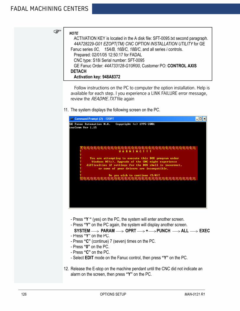
FADAL MACHINING CENTERS
126
NOTE
ACTIVATION KEY is located in the A disk file: SFT-0095.txt second paragraph. 44A728229-G01 EZOPT(TM) CNC OPTION INSTALLATION UTILITY for GE Fanuc series 0C, 15A/B, 16B/C, 18B/C, and all series i controls. Prepared: 02/01/05 12:50:17 for FADAL CNC type: S18i Serial number: SFT-0095 GE Fanuc Order: 44A733128-G10R00, Customer PO: CONTROL AXIS DETACH Activation key: 948A8372 Follow instructions on the PC to computer the option installation. Help is available for each step. I you experience a LINK FAILURE error message, review the README.TXT file again
11. The system displays the following screen on the PC.
- Press “Y “ (yes) on the PC, the system will enter another screen.- Press “Y” on the PC again, the system will display another screen.
- Press “Y” on the PC.- Press “C” (continue) 7 (seven) times on the PC.- Press “0” on the PC.- Press “C” on the PC.- Select EDIT mode on the Fanuc control, then press “Y” on the PC.
12. Release the E-stop on the machine pendant until the CNC did not indicate an alarm on the screen, then press “Y” on the PC.
SYSTEM PARAM OPRT + PUNCH ALL EXEC
OPTIONS SETUP MAN-0121 R1

AUGUST 2005
FANUC MAINTENANCE MANUAL
13. Verify wether series cable is connected from PC to Fanuc CNC, then press “Y” on the PC.
14. Check the download link:
- Quickly press following keys and soft keys on the Fanuc control:- Until the PC displays press MDI and RESET, then press MDI key and RESET key on the machine pendant. - Press “Y” on the PC if screen displays saying, “Link Ok ...... Continue?”- Press EDIT on the pendant again.** Press “Y” on the PC to repeat step 14. (above) if download link check has failed.
15. Download parameters
- Quickly press following keys and soft keys on the Fanuc control:
- Press “Y” on the PC until the screen displays saying, “Download ok .... Continue?”** Press “Y” on the PC to repeat step 15. (above) if download parameter has failed.
16. Select “MDI” mode on the machine pendant, then press “Y” on the PC.
17. Press E-stop switch on the machine pendant until the CNC enters the E-stop status, then press “C” on the PC.
18. Upload link check.
- Quickly press following keys and soft keys on the Fanuc control:
- Press “Y” on the PC until the screen displays saying, “Option successfully updated?” - Press “Y” on the PC to repeat step 18. (above) if upload parameter has failed.
19. Cycle the CNC power. Once CNC displays the “normal” screen press “C” on the PC.
20. Press any key to exit the Fanuc software update program.
21. Check all the files and make sure that files still are in the system.(Program library, CNC parameter, PMC parameter, PMC ladder, Pitch compensation, Offset, Macro Variable.)
22. Set a new cold start position on the machine according the “Cold start procedure” (See Machine Cold Start Setup, Section 6.2, MAN-0121-R1).
SYSTEM PARAM OPRT + PUNCH ALL EXEC
SYSTEM PARAM OPRT + READ EXEC
OPTIONS SETUP 127

FADAL MACHINING CENTERS
128
23. Run the program O8851 to recover the communication parameter to original one.
- Press EDIt key on the pendant.- Press PROG key on the MDI panel.- Press DIR soft key on the LCD screen.- Input O8851.- Press NO.SRH soft key on the LCD screen, the program will display on the screen.- Press DOOR OVR (the light above the DOOR OVR key should flick).- Press AUTO key on the pendant.- Press CYCLE START key to run the program.- Make sure the program is completed and M30 is displayed on the screen area.
24. Load backup pacific files from the flashcard to CNC and make sure if files still are in the system.
25. Setup is completed.
OPTIONS SETUP MAN-0121 R1
FANUC MAINTENANCE MANUAL
6.2 MACHINE COLD START SETUP
AUGUST 2005
Fadal Fanuc VMC comes with absolute encoders which is setup at Fadal already. The machine will remember the position even if it is powered off. We need to remake the cold start position if the alarm No.300 appears on the screen which can be caused by a low battery or disconnect the servo motor encoder.
Follow the next procedure:1. Prepare: In MDI mode input G21 to change machine to Metric display.
1.1 Press the MDI push button on the operator panel A.
1.2 Press PROGRAM key one/two times on the MDI panel until PROGRAM (MDI) screen is displayed.
1.3 Press G21 using MDI panel.
1.4 Press EOB key on the MDI panel.
1.5 Press INSERT key.
1.6 Press CYCLE START push button on the operator panel A.
1.7 Make sure the screen is changed to Metric Mode (X***,*** is displayed).
1.8 Press REF RETURN push button on the operator panel A.
1.9 Press Z push button on the operator panel A (Manual Z axis zero return).
1.10 Press X push button on the operator panel A (Manual X axis zero return).
1.11 Press Y push button on the operator panel A (Manual Y axis zero return).
1.12 Preparation is done.
2. Install the tool.
2.1 Press JOG push button on the operator panel A.
2.2 Press TOOL REL push button on the operator panel and keep it. (Draw Bar will be released)
2.3 Put the tool inside of spindle nose.
2.4 Release the TOOL REL push button.
3. Find out X axis zero position manually, make the cold start.
3.1 Press HANDLE and select MPG mode, press X1/X10/X100 to select MPG resolution, and press X select to select X axis.
3.2 Use TAPE MEASURE find out the X axis middle point of the table, and make a mark.
OPTIONS SETUP 129

FADAL MACHINING CENTERS
130
3.3 Use MPG move the X axis to the X axis middle potion mark.
3.4 Record the X coordinate displayed on the CNC screen as A.
3.5 Press MDI push button on the operator panel A.
3.6 Press SYSTEM key on the MDI panel.
3.7 Press PARAMETER soft key below the LCD screen.
3.8 Press 1850 using MDI panel.
3.9 Press NO.SRH soft key below the LCD screen (Parameter 1850 will be displayed).
3.10 Move the cursor to X.
3.11 Press the X coordinator as following format: 34560 (3.456x10000).
3.12 Press INPUT key on the MDI panel (34560 will be displayed on the parameter 1850X column) ***Alarm 000 will pop up on the alarm window.
3.13 Power OFF the CNC (Press “O” button on the operator panel B).
3.14 Power ON the CNC (Press “T” button on the operator panel B). ***Alarm 300X will be displayed on the screen (it is normal).
3.15 Press JOG push button on the operator panel A.
3.16 Press X push button on the operator panel A.
3.17 Press “-” minus push button to move the X axis 55.0mm or more (press “+” push button if machine is 2016, 3016, EMCD, 2216).
3.18 Press “+” plus push button to move the X axis middle position (press “-” push button if machine is 2016, 3016, EMCD, 2216).
3.19 Press REF RETURN push button.
3.20 Press X push button. (X axis will automatically move to the zero position)
3.21 In case if zero position is wrong, repeat the previous steps starting with pressing MDI push button of the operator panel A.
3.22 Double check the cold start position using tape measure.
3.23 Press RESET key on the MDI panel. That will reset the 300 alarm.
4. Find out Y axis zero position manually, make the cold start. 4.1 Install the indicator on the spindle.
4.2 Repeat the same procedure as 4.1-4.23 to find out the Y axis cold start position.
OPTIONS SETUP MAN-0121 R1

AUGUST 2005
FANUC MAINTENANCE MANUAL
5. Find out Z axis zero position manually, make the cold start. 5.1 Install tool on the arm (DATC) or Magazine (ATC).
5.2 Measure the height of the tool.
5.3 Install the tool on the spindle.
5.4 Use MPG move the Z axis to the same height as the tool on the ARM/Magazine.
5.5 Repeat the same procedure as 4.5-1.23 to find out the Z axis cold start position.
6. Repeat the same procedure for A/B axis.
7. Cold Start setup is finished.
OPTIONS SETUP 131

FADAL MACHINING CENTERS
6.3 TOOL OFFSET SETUP
132
Fanuc Software option related with tool offset.
6.3.1 TOOL OFFSET 200 PAIRS
1. Update the software option from EZOPT disk according to Fanuc Software Option Installation Procedure. (See Option Installation process, section 6.1.1)
2. Cycle the CNC power.
3. Follow these steps to display the following screen:
- Press OFFSET/SETTING key on the MDI panel.- Press OFFSET soft key on the LCD screen.- Press PAGE UP key once on the MDI screen.- Check the following screen on the CNC. If 200 pairs offset appears on the screen, the software installation is successful. Otherwise, repeat all the steps above all over again.
6.3.2 TOOL OFFSET 400 PAIRS
1. Update the software option form EZOPT disk according to Fanuc Software Option Installation Procedure. (See section 6.1, MAN-0121 R1)
2. Cycle the CNC power.
3. Follow these steps to display the following screen.
- Press OFFSET/SETTING key on the MDI panel.- Press OFFSET soft key on the LCD screen.
OPTIONS SETUP MAN-0121 R1
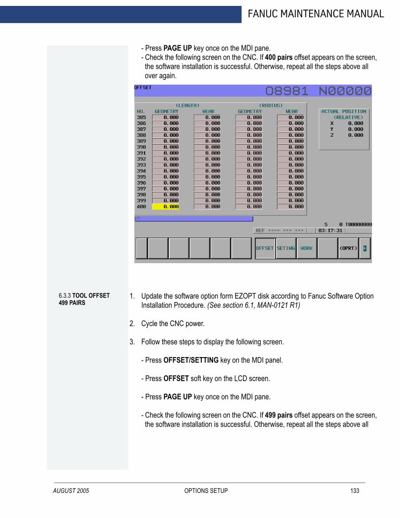
AUGUST 2005
FANUC MAINTENANCE MANUAL
- Press PAGE UP key once on the MDI pane.- Check the following screen on the CNC. If 400 pairs offset appears on the screen, the software installation is successful. Otherwise, repeat all the steps above all over again.
6.3.3 TOOL OFFSET 499 PAIRS
1. Update the software option form EZOPT disk according to Fanuc Software Option Installation Procedure. (See section 6.1, MAN-0121 R1)
2. Cycle the CNC power.
3. Follow these steps to display the following screen.
- Press OFFSET/SETTING key on the MDI panel.
- Press OFFSET soft key on the LCD screen.
- Press PAGE UP key once on the MDI pane.
- Check the following screen on the CNC. If 499 pairs offset appears on the screen, the software installation is successful. Otherwise, repeat all the steps above all
OPTIONS SETUP 133

FADAL MACHINING CENTERS
134
over again.
6.3.4 TOOL OFFSET 999 PAIRS
1. Update the software option form EZOPT disk according to Fanuc Software Option Installation Procedure. (See section 6.1, MAN-0121 R1)
2. Cycle the CNC power.
3. Follow these steps to display the following screen.
- Press OFFSET/SETTING key on the MDI panel.- Press OFFSET soft key on the LCD screen.- Press PAGE UP key once on the MDI pane.- Check the following screen on the CNC. If 999 pairs offset appears on the screen, the software installation is successful. Otherwise, repeat all the steps above all over again.
OPTIONS SETUP MAN-0121 R1

AUGUST 2005
FANUC MAINTENANCE MANUAL
OPTIONS SETUP 135

FADAL MACHINING CENTERS
6.4 MULTI STEP SKIP
136
Follow the next procedure:
1. Update the software option from EZOPT disk according to the Fanuc Software Option Installation Procedure. (See section 6.1, MAN-0121 R1)
2. Install the probe hardware and make sure that signal is working properly TS27R, MP12.
3. Input the testing program O5004 from EDIT mode.
O5004 (MULTI STEP SKIP)N01 G01 G90N02 G28X0Y0Z0N03 G31P1X5.0F10.0N04 G31P2Y5.0F10.0N05 G31P3Z-5.0F10.0N06 M30
4. Run the testing program O5004 from AUTO mode.
- Press EDIT key to select edit mode.- Press PROG key on the MDI panel.- Press DIR soft key on the LCD screen.- Input O5004.- Press INPUT key on the MDI panel.- Press O.SRH soft key on the LCD screen, make sure that program displays on the screen.- Press AUTO key on the machine pendant.- Press DOOR OVR key on the machine pendant until the door override is enabled.- Press CYCLE START key on the machine pendant.
5. Press the probe head to trig the probe MP12 when the program is running at block N03. If program skips to the next block N04 as soon as one trig the probe, MP12 is working.
6. Press the probe head to trig the probe TR27R when the program is running at block N04. If program skips to the next block N05 as soon as one trig the probe, TS27R is working.
7. Block the beam of NC1 to trig the probe NC1 when the program is running at block N05. If program skips to the next block N06 as soon as one trig the probe, NC1 is working.
8. If steps from 5. through 7. are succeeded without an alarm alert, the software installation is successful. Otherwise, repeat these steps all over again.
OPTIONS SETUP MAN-0121 R1
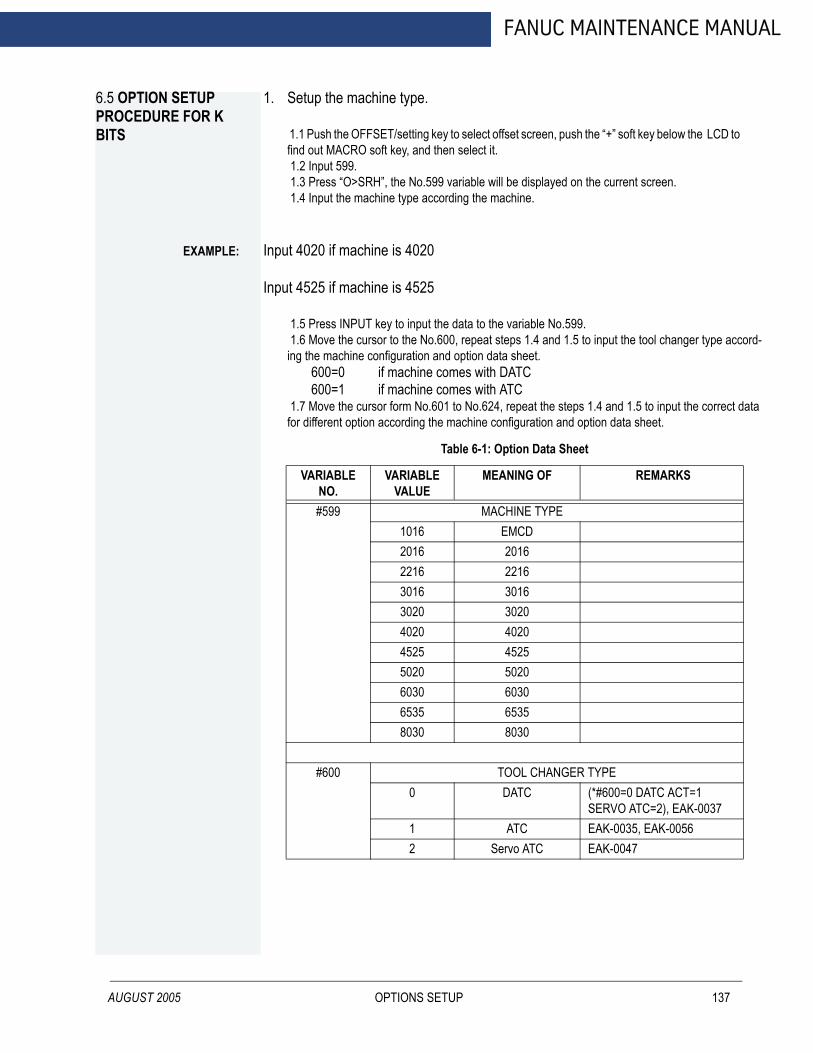
FANUC MAINTENANCE MANUAL
6.5 OPTION SETUP PROCEDURE FOR K BITS
AUGUST 2005
1. Setup the machine type.
1.1 Push the OFFSET/setting key to select offset screen, push the “+” soft key below the LCD to find out MACRO soft key, and then select it. 1.2 Input 599. 1.3 Press “O>SRH”, the No.599 variable will be displayed on the current screen. 1.4 Input the machine type according the machine.
EXAMPLE:
Input 4020 if machine is 4020Input 4525 if machine is 4525
1.5 Press INPUT key to input the data to the variable No.599. 1.6 Move the cursor to the No.600, repeat steps 1.4 and 1.5 to input the tool changer type accord-ing the machine configuration and option data sheet.
600=0 if machine comes with DATC600=1 if machine comes with ATC
1.7 Move the cursor form No.601 to No.624, repeat the steps 1.4 and 1.5 to input the correct data for different option according the machine configuration and option data sheet.
Table 6-1: Option Data Sheet
VARIABLE NO.
VARIABLE VALUE
MEANING OF REMARKS
#599 MACHINE TYPE1016 EMCD2016 20162216 22163016 30163020 30204020 40204525 45255020 50206030 60306535 65358030 8030
#600 TOOL CHANGER TYPE0 DATC (*#600=0 DATC ACT=1
SERVO ATC=2), EAK-00371 ATC EAK-0035, EAK-00562 Servo ATC EAK-0047
OPTIONS SETUP 137

FADAL MACHINING CENTERS
138
Table 6-1: (Continued) Option Data Sheet
VARIABLE NO.
VARIABLE VALUE
MACHINE TYPE REMARKS
#601 TOOL CHANGER POCKET NUMBER
16 ATC (*#601=24 MAGZINE POCKET NO.), ATC/DATC
21 ATC
30 ATC
20 DATC
24 DATC
32 DATC
62 DATC
40 HMC DATC
92 HMC DATC
#602 EXTEND COLUMN SELECTION
0 Standard column (*#602=0 STD=0 EXTEND COLUMN=1)
1 Extend column
#603 SPINDLE MOTOR TYPE
1 10HP/7.5KW Fanuc spindle motor
Spindle motor type (STD)
2 15HP/11KW Fanuc spindle motor
(High Torque Fanuc motor)
3 20HP/15KW Fanuc spindle motor
(Very High Torque Fanuc motor)
4 30HP/22.5KW Fanuc spindle motor
(Fanuc motor for 6535)
#604 SPINDLE GEAR SHIFT SELECTION
1 Mech HI/LO
2 Elec. HI/LO
3 Neither Mech. nor Elec.
OPTIONS SETUP MAN-0121 R1

AUGUST 2005
FANUC MAINTENANCE MANUAL
#605
SPINDLE MAX CLAMP SPEED
7500 7500RPM 7.5K Spindle
10000 10000RPM 15KSpindle 7.5 k
15000 15000RPM 15K Spindle
#606 SPINDLE SHIFT SPEED (*spare parameter)
2501 Mech HI/LO=2501. Electrical HI/LO=2501
#610 A AXIS SELECTION
0 No A axis
1 A axis exists
#611 B AXIS SELECTION
0 No B axis
1 B axis exists
#612 X AXIS SCALE SELECTION
0 No X axis scale EAK-0041
1 X axis exists EAK-0041
#613 Y AXIS SCALE SELECTION
0 No Y axis scale EAK-0041
1 Y axis exists EAK-0041
#614 Z AXIS SCALE SELECTION
0 No Z axis scale EAK-0041
1 Z axis exists EAK-0041
Table 6-1: (Continued) Option Data Sheet
VARIABLE NO.
VARIABLE VALUE
MACHINE TYPE REMARKS
OPTIONS SETUP 139

FADAL MACHINING CENTERS
140
#615 A AXIS SCALE SELECTION
0 No A axis scale EAK-0041
1 A axis exists EAK-0041
#616 B AXIS SCALE SELECTION
0 No B axis scale
1 B axis exists
#617 A AXIS TYPE SELECTION
1 VH165 A4/5000is, EAK-0042
2 TR165 A4/5000is, EAK-0043
3 V300/V400 B8/3000is, EAK-0044
4 SMW-175 A2/5000i, EAK-0063
5 SMW-225/275 AC8/2000i, EAK-0064
#618 B AXIS TYPE SELECTION
2 TR165 A4/5000is, EAK-0043
#619 SPEED
0 Standard rapid speed
1 1200IPM rapid speed
#620 AIR OIL SELECTION
0 No
1 Yes
#621 MIDACO PALLET
0 No EAK-0046
1 Yes EAK-0046
Table 6-1: (Continued) Option Data Sheet
VARIABLE NO.
VARIABLE VALUE
MACHINE TYPE REMARKS
OPTIONS SETUP MAN-0121 R1

AUGUST 2005
FANUC MAINTENANCE MANUAL
1.8 Run the option program from O8800 to O8805 one by one to active all the options.1.8.1 Press EDIT key to select edit mode, and push PROGRAM key on the MDI keyboard until
program directory is displayed on the CNC screen..1.8.2 Use PAGE UP/PAGE DOWN key to review all the programs inside CNC.1.8.3 Input O8800 using MDI keyboard, and push CURSOR DOWN to call this program out
and display it on the CNC program window.1.8.4 Press AUTO key to select Auto mode and press CYCLE START key to execute the
program.1.8.5 After executing program O8800, and CNC screen indicates an alarm “000”, cycle the
CNC Power.1.8.6 Repeat steps 1.8.1 through 1.8.5 to execute all the option programs:
O8800: Soft limit and ATC optionO8801 : Spindle motor setupO8803: PMC data setupO8804: A axis setupO8805: B axis setup
1.9 Cycle the power again. 1.10 Disable the 1050 alarm by seting the K4.6=1 if it is mechanical HI/LO.
If the machine comes with a mechanical High/Low gear shift, this alarm will come out after first power on. Operator can disable the alarm by following procedure, but this bit should be changed back to “0” when the spindle is ready to run.
- Press MDI to change the to the MDI mode- Press SYSTEM key on the MDI panel(press one more time if it need until the parameter
screen comes out)
#622 WAY LUBRICATION TYPE
0 Except PDI TYPE (with air solenoid)
1 2016L, 3016L, 4020A, 5020A
NO-PDI TYPE (without air sole-noid)
#623 COOL SPINDLE OPTION
0 No EAK-0070
1 Yes Only 2216, 2016, 3016
#630 CHANGE X AXIS DIRECTION
0 No
1 Yes
Table 6-1: (Continued) Option Data Sheet
VARIABLE NO.
VARIABLE VALUE
MACHINE TYPE REMARKS
OPTIONS SETUP 141
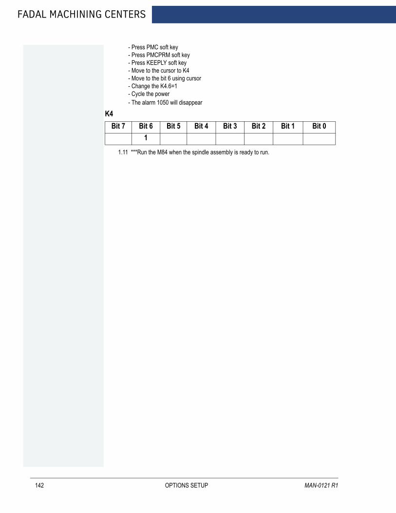
FADAL MACHINING CENTERS
142
- Press PMC soft key- Press PMCPRM soft key- Press KEEPLY soft key- Move to the cursor to K4- Move to the bit 6 using cursor- Change the K4.6=1- Cycle the power- The alarm 1050 will disappear
1.11 ***Run the M84 when the spindle assembly is ready to run.
K4Bit 7 Bit 6 Bit 5 Bit 4 Bit 3 Bit 2 Bit 1 Bit 0
1
OPTIONS SETUP MAN-0121 R1

FANUC MAINTENANCE MANUAL
6.6 MACHINE TIME STAMP
AUGUST 2005
Follow the next procedure:
1. Update the software option from EZOPT disk according to Fanuc software option installation procedure.
2. Input the testing program P5006 from EDIT mode.
3. Run the testing program O5006 from AUTO mode.
• Press EDIT key to select edit mode• Press PROG key on the MDI keyboard• Press DIR soft key on the LCD screen• Input O5006• Press INPUT key on the MDI panel• Press O.SRG soft key on the LCD screen, make sure that program comes out on
the screen• Press AUTO key on the machine pendant• Press DOOR OVR key on the machine pendant until the door override is enabled.
4. Machine time calculation procedure.
• Select the memory operation mode, then press RESET key• Press CYCLE START button on the machine pendant to execute the program to
perform actual machining• When O5006 is complete, machining time count operation stops
5. Display machine time. When machining time display screen is selected, the pro-gram number of the stopped program and it’s machining time are displayed.
• Press the function key PROG• Press the rughtmost soft key “+” once or twice to display soft key TIME• Press soft key TIME
Machining time screen displays.
OPTIONS SETUP 143

FADAL MACHINING CENTERS
144
O5006G21G91G02 X3.0Y5.0R3.1234567M30
OPTIONS SETUP MAN-0121 R1

FANUC MAINTENANCE MANUAL
6.7 MOUNTING AND REMOVING OPTION BOARD
AUGUST 2005
WARNING! The replacement described here should be performed by a person fully trained in maintenance and safety. If the care not to touch any high–voltage area. If the area is uncovered, direct contact with this area will result in an electric shock. cabinet is opened to replace the option board, take extreme.
NOTE Before starting the replacement, take a back–up copy of the contents (parameters, programs, etc.) of the SRAM memory of the CNC. The backup copy can be used in case the contents of the SRAM memory are lost during the replacement.
6.7.1 MOUNTING AND REMOVING MAIN CPU BOARD AND FULL-SIZE OPTION BOARD
Removing the board
1. Removing cables other than the battery cable. (The battery cable is connected only to the main CPU board.)
2. Hold handles A and B.
3. Pushing down the hook of handle A and pushing up the hook of handle B, pull out the printed circuit board.
NOTE 1 The battery is mounted on the face place of the main CPU board. The battery is pulled out together with the main CPU board. 2 The main CPU board or a full–size option board can be removed without removing mini–slot option boards. (If a cable connected to a mini–slot option board obstructs the removal, the cable must be removed.)
Mounting the board
1. Holding handles A and B, insert the board into the cabinet until the connector on the back panel is connected.
OPTIONS SETUP 145
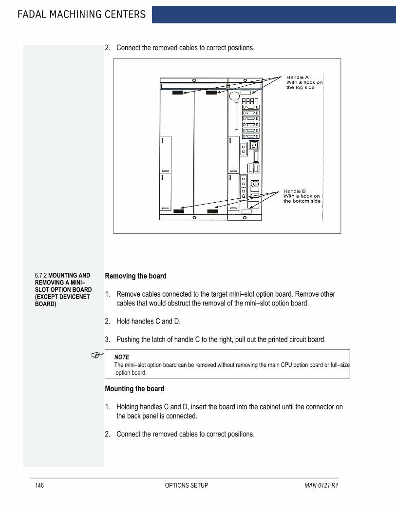
FADAL MACHINING CENTERS
146
2. Connect the removed cables to correct positions.
6.7.2 MOUNTING AND REMOVING A MINI–SLOT OPTION BOARD (EXCEPT DEVICENET BOARD)
Removing the board
1. Remove cables connected to the target mini–slot option board. Remove other cables that would obstruct the removal of the mini–slot option board.
2. Hold handles C and D.
3. Pushing the latch of handle C to the right, pull out the printed circuit board.
NOTE The mini–slot option board can be removed without removing the main CPU option board or full–size option board.
Mounting the board
1. Holding handles C and D, insert the board into the cabinet until the connector on the back panel is connected.
2. Connect the removed cables to correct positions.
OPTIONS SETUP MAN-0121 R1

AUGUST 2005
FANUC MAINTENANCE MANUAL
6.7.3 MOUNTING AND REMOVING THE BACK PANEL
WARNING!The replacement described here should be performed by a person fully trained in maintenance and safety. If the care not to touch any high–voltage area. If the area is uncovered, direct contact with this area will result in an electric shock. cabinet is opened to replace the back panel, take extreme.
NOTE Before starting the replacement, take a back–up copy of the contents (parameters, programs, etc.) of the SRAM memory of the CNC. The backup copy can be used in case the contents of the SRAM memory are lost during the replacement.
Removing the Panel
1. Remove the main CPU board and all option boards, following the steps described in Section 3.6.
2. Remove the connector of the fan connected to the back panel.
3. Push down the latch securing the back panel until the latch is disengaged.
4. Pull down and detach the back panel to the rear.
Mounting the Back Panel
1. Aligning the positioning hole of the back panel with the positioning pin, fit the back panel on from the rear.
OPTIONS SETUP 147
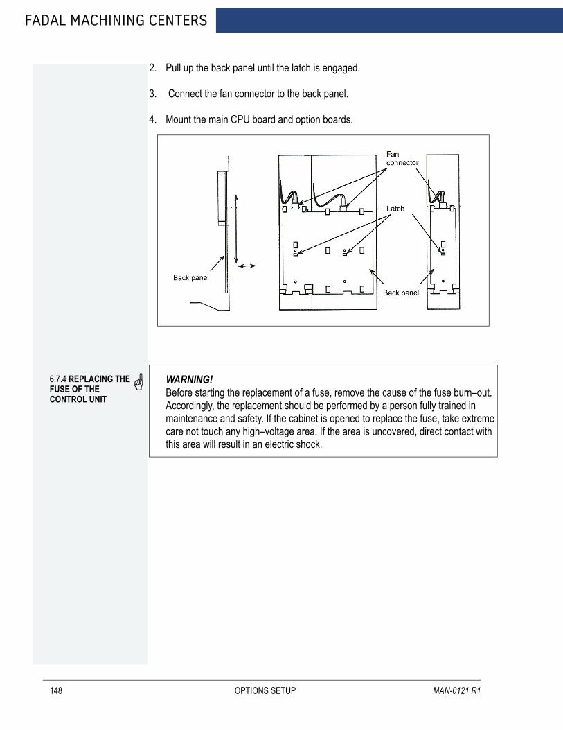
FADAL MACHINING CENTERS
148
2. Pull up the back panel until the latch is engaged.
3. Connect the fan connector to the back panel.
4. Mount the main CPU board and option boards.
6.7.4 REPLACING THE FUSE OF THE CONTROL UNIT
WARNING! Before starting the replacement of a fuse, remove the cause of the fuse burn–out. Accordingly, the replacement should be performed by a person fully trained in maintenance and safety. If the cabinet is opened to replace the fuse, take extreme care not touch any high–voltage area. If the area is uncovered, direct contact with this area will result in an electric shock.
OPTIONS SETUP MAN-0121 R1
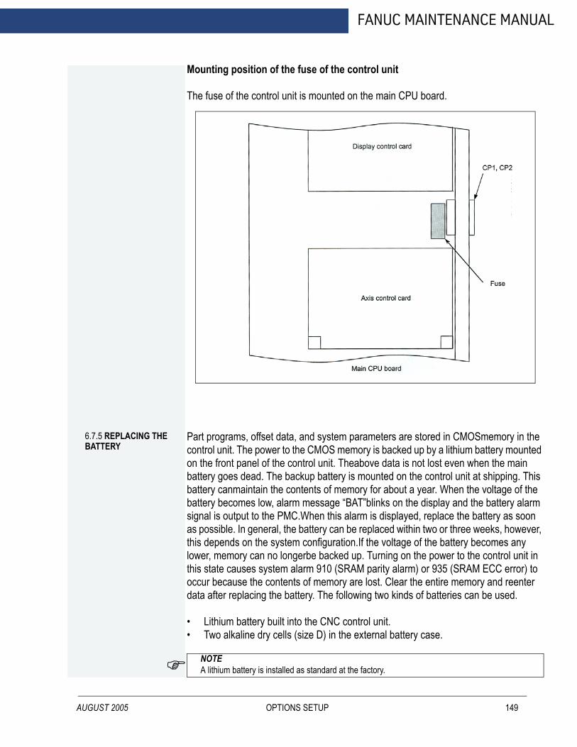
AUGUST 2005
FANUC MAINTENANCE MANUAL
Mounting position of the fuse of the control unit
The fuse of the control unit is mounted on the main CPU board.
6.7.5 REPLACING THE BATTERY
Part programs, offset data, and system parameters are stored in CMOSmemory in the control unit. The power to the CMOS memory is backed up by a lithium battery mounted on the front panel of the control unit. Theabove data is not lost even when the main battery goes dead. The backup battery is mounted on the control unit at shipping. This battery canmaintain the contents of memory for about a year. When the voltage of the battery becomes low, alarm message “BAT”blinks on the display and the battery alarm signal is output to the PMC.When this alarm is displayed, replace the battery as soon as possible. In general, the battery can be replaced within two or three weeks, however, this depends on the system configuration.If the voltage of the battery becomes any lower, memory can no longerbe backed up. Turning on the power to the control unit in this state causes system alarm 910 (SRAM parity alarm) or 935 (SRAM ECC error) to occur because the contents of memory are lost. Clear the entire memory and reenter data after replacing the battery. The following two kinds of batteries can be used.
• Lithium battery built into the CNC control unit.• Two alkaline dry cells (size D) in the external battery case.
NOTE A lithium battery is installed as standard at the factory.
OPTIONS SETUP 149
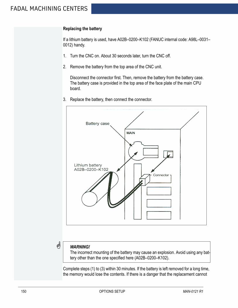
FADAL MACHINING CENTERS
150
Replacing the battery
If a lithium battery is used, have A02B–0200–K102 (FANUC internal code: A98L–0031–0012) handy.
1. Turn the CNC on. About 30 seconds later, turn the CNC off.
2. Remove the battery from the top area of the CNC unit.
Disconnect the connector first. Then, remove the battery from the battery case. The battery case is provided in the top area of the face plate of the main CPU board.
3. Replace the battery, then connect the connector.
WARNING! The incorrect mounting of the battery may cause an explosion. Avoid using any bat-tery other than the one specified here (A02B–0200–K102).
Complete steps (1) to (3) within 30 minutes. If the battery is left removed for a long time, the memory would lose the contents. If there is a danger that the replacement cannot
OPTIONS SETUP MAN-0121 R1
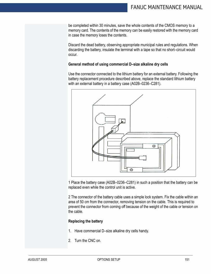
AUGUST 2005
FANUC MAINTENANCE MANUAL
be completed within 30 minutes, save the whole contents of the CMOS memory to a memory card. The contents of the memory can be easily restored with the memory card in case the memory loses the contents.
Discard the dead battery, observing appropriate municipal rules and regulations. When discarding the battery, insulate the terminal with a tape so that no short–circuit would occur.
General method of using commercial D–size alkaline dry cells
Use the connector connected to the lithium battery for an external battery. Following the battery replacement procedure described above, replace the standard lithium battery with an external battery in a battery case (A02B–0236–C281).
1 Place the battery case (A02B–0236–C281) in such a position that the battery can be replaced even while the control unit is active.2 The connector of the battery cable uses a simple lock system. Fix the cable within an area of 50 cm from the connector, removing tension on the cable. This is required to prevent the connector from coming off because of the weight of the cable or tension on the cable.
Replacing the battery
1. Have commercial D–size alkaline dry cells handy.
2. Turn the CNC on.
OPTIONS SETUP 151
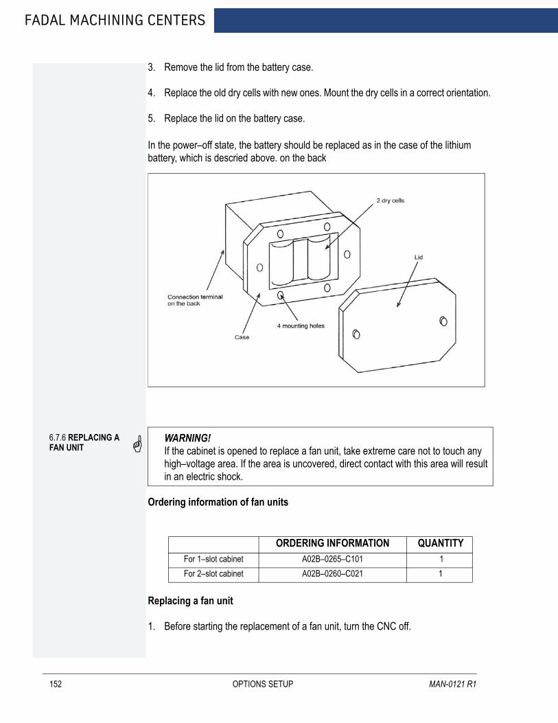
FADAL MACHINING CENTERS
152
3. Remove the lid from the battery case.
4. Replace the old dry cells with new ones. Mount the dry cells in a correct orientation.
5. Replace the lid on the battery case.
In the power–off state, the battery should be replaced as in the case of the lithium battery, which is descried above. on the back6.7.6 REPLACING A FAN UNIT
WARNING!If the cabinet is opened to replace a fan unit, take extreme care not to touch any high–voltage area. If the area is uncovered, direct contact with this area will result in an electric shock.
Ordering information of fan units
Replacing a fan unit
1. Before starting the replacement of a fan unit, turn the CNC off.
ORDERING INFORMATION QUANTITY For 1–slot cabinet A02B–0265–C101 1For 2–slot cabinet A02B–0260–C021 1
OPTIONS SETUP MAN-0121 R1
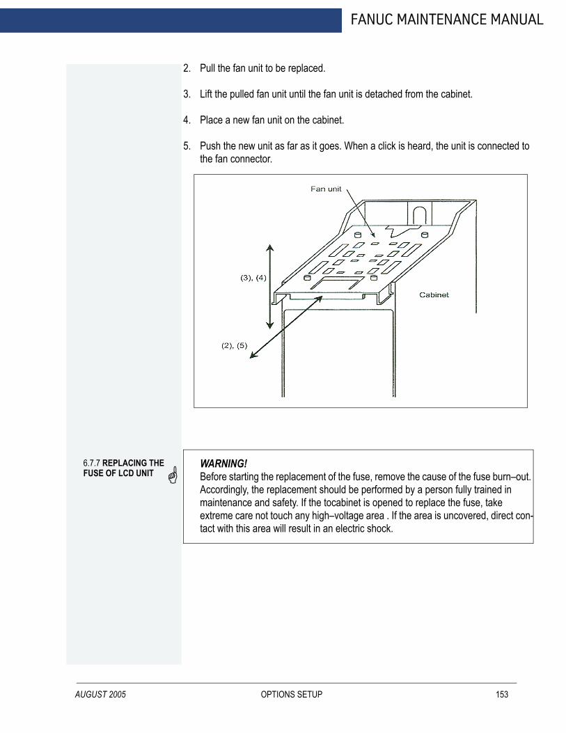
AUGUST 2005
FANUC MAINTENANCE MANUAL
2. Pull the fan unit to be replaced.
3. Lift the pulled fan unit until the fan unit is detached from the cabinet.
4. Place a new fan unit on the cabinet.
5. Push the new unit as far as it goes. When a click is heard, the unit is connected to the fan connector.
6.7.7 REPLACING THE FUSE OF LCD UNIT
WARNING!Before starting the replacement of the fuse, remove the cause of the fuse burn–out. Accordingly, the replacement should be performed by a person fully trained in maintenance and safety. If the tocabinet is opened to replace the fuse, take extreme care not touch any high–voltage area . If the area is uncovered, direct con-tact with this area will result in an electric shock.
OPTIONS SETUP 153

FADAL MACHINING CENTERS
154
Mounting position of the fuse
• Information of the fuse Ordering information: A02B–0265–K101 Rating: 2.0 A Individual information: A60L–0001–0290#LM20C
6.7.8 REPLACING THE LCD BACKLIGHT
WARNING! The replacement described here should be performed by a person fully trained in maintenance and safety. If the tocabinet is opened to replace the unit, take extreme care not touch any high–voltage area . If the area is uncovered, direct contact with this area will result in an electric shock.
Ordering information of the backlight
NOTE The back–light of the 10.4 color LCD cannot be replaced.
Backlight Ordering information Individual informationFor 9.5’’LCD A02B–0281–K114 A61L–0001–0154#BLC
OPTIONS SETUP MAN-0121 R1
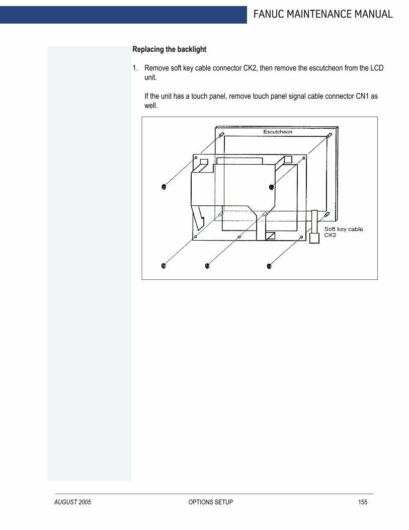
AUGUST 2005
FANUC MAINTENANCE MANUAL
Replacing the backlight
1. Remove soft key cable connector CK2, then remove the escutcheon from the LCD unit.
If the unit has a touch panel, remove touch panel signal cable connector CN1 as well.
OPTIONS SETUP 155
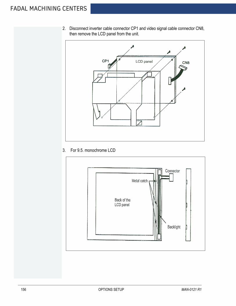
FADAL MACHINING CENTERS
156
2. Disconnect inverter cable connector CP1 and video signal cable connector CN8, then remove the LCD panel from the unit.
3. For 9.5. monochrome LCD
OPTIONS SETUP MAN-0121 R1
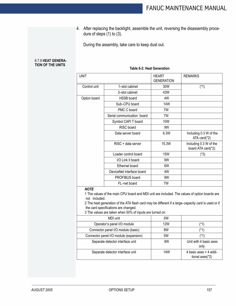
AUGUST 2005
FANUC MAINTENANCE MANUAL
4. After replacing the backlight, assemble the unit, reversing the disassembly proce-dure of steps (1) to (3).
During the assembly, take care to keep dust out.
6.7.9 HEAT GENERA-TION OF THE UNITS
Table 6-2: Heat Generation
UNIT HEART GENERATION
REMARKS
Control unit 1–slot cabinet 30W (*1)3–slot cabinet 43W
Option board HSSB board 4WSub–CPU board 14W
PMC C board 7WSerial communication board 7W
Symbol CAPi T board 10WRISC board 9W
Data server board 6.3W Including 0.3 W of the ATA card(*2)
RISC + data server 15.3W Including 0.3 W of the board ATA card(*2)
Loader control board 15W (*3) I/O Link II board 9WEthernet board 6W
DeviceNet interface board 4WPROFIBUS board 9W
FL–net board 7WNOTE 1 The values of the main CPU board and MDI unit are included. The values of option boards are not included. 2 The heat generation of the ATA flash card may be different if a large–capacity card is used or if the card specifications are changed. 3 The values are taken when 50% of inputs are turned on.
MDI unit 0WOperator’s panel I/O module 12W (*1)
Connector panel I/O module (basic) 8W (*1) Connector panel I/O module (expansion) 5W (*1)
Separate detector interface unit 9W Unit with 4 basic axes only
Separate detector interface unit 14W 4 basic axes + 4 addi-tional axes(*2)
OPTIONS SETUP 157

FADAL MACHINING CENTERS
158
NOTE 1 The values are taken when 50% of the module inputs are turned on. 2 The heat generated in the separate detector is not included.
OPTIONS SETUP MAN-0121 R1

FANUC MAINTENANCE MANUAL
AUGUST 2005
7.0 AUTOMATIC TOOL CHANGERS
VMC models 3020, 4525, 6535 come standard with the Dual Arm Tool Changer. VMC models 2216, 3016, 4020, 6030, 8030 (DATC optional) come standard with a 21 tool capacity (30 tool capacity optional for 4020, 6030, 8030) Geneva drive tool changer.
AUTOMATIC TOOL CHANGERS 159

FADAL MACHINING CENTERS
7.1 OPERATION
7.1.1PROGRAMMING
160
To make an automatic tool change, an M6 code is used. This code can be used in a program or in Manual Data Input (MDI) mode.
In a Program
When another tool is needed, an M6 followed by a tool location. (T_) is entered and the tool changer will make the appropriate tool change and then continue on with the program.
In MDI
The operator can make a tool change with out running a program. If the operator is testing the tool changer or setting tool lengths, the M6 code followed by the tool location will command the tool changer to make the necessary tool change.
7.1.2 TOOL CHANGE SEQUENCE
The following is the order of operations for the CNC when making a tool change (Geneva driven ):
1. Move the Z axis to the machine home (Cold Start) position.
2. Turn the spindle slowly while looking for the Orientation Sensor signal.
3. When orientation signal is received, stop the spindle.
4. Activate the orientation arm.
5. Move the ATC turret to the tool position of the tool in the spindle.
6. Verify the orientation sensor.
7. Check the ATC Home sensor and verify that the ATC is at the home position.
8. Activate the ATC slide reverse circuit.
9. Activate the ATC slide motor circuit.
10. Watch for the ATC extended sensor signal.
11. Stop the slide motor when the extended position sensor is read.
12. Activate the draw bar.
13. Watch for the drawbar sensor detection (air feed parameter).
14. Check for the ATC fault switch.
15. Move the Z axis up to 3.8” above the cold start position.
AUTOMATIC TOOL CHANGERS MAN-0121 R1

AUGUST 2005
FANUC MAINTENANCE MANUAL
16. Activate the turret motor and the turret reverse (if the reverse direction is required)circuit(s).
17. Count the turret sensor signals, with a dwell time for coasting as set by the turretfactor, until the requested tool position is reached.
18. Stop the turret motor.
19. Move the Z axis downward to the machine home position.
20. Check for the ATC fault switch.
21. Release the drawbar circuit.
22. Activate the ATC slide motor.
23. Watch for the ATC Home sensor, to determine the ATC home position.
24. Stop the ATC slide motor.
25. Release the orientation arm.
NOTE The hall effect sensors have three wires. One for 5vdc, one for ground, and one for the signal. The signal will be about 5vdc until a magnet is over it, then it will become active, and the signal will be about zero.
7.1.3 ATC FAULT MESSAGES
ATC FAILURE: The machine is receiving a signal from the ATC fault switch. This would indicate that the ATC spindle is out of position. Check the position of the ATC spindle. If it is in the proper position, check the switch, the switch wiring.
ATC TURRET FAILURE: The machine did not receive a signal from the ATC Turret Sensor, when the tool position change was commanded. If the turret moved to the next position, then the sensor is not operating. This could be caused by a bad sensor, wiring problem, sensor to magnet spacing, or chips on the sensor or magnet. If the turret does not move, then the turret motor circuit is not operating. This may be caused by a mechanical bind, turret motor, wiring problem.
ATC WILL NOT MOVE TO POSITION: When the ATC is commanded to move to either the extended or home positions and the appropriate sensor does not send a signal within the allotted time, this fault is displayed. The possible causes for this fault are mechanical problems including chips in the track area preventing the rollers from rolling, misalignment of the ATC or spindle position, bad sensor or gap setting on cylinder, wiring problem, motor.
ATC WILL NOT MOVE TO SPINDLE: Same as the ATC WILL NOT MOVE INTO POSITION except the direction (reverse) is known.
AUTOMATIC TOOL CHANGERS 161

FADAL MACHINING CENTERS
7.2 ADJUSTMENTS
162
There are four motions that influence the automatic tool changer alignment. These motions are:
• Z-axis up & down.• Spindle orientation.• Turret in & out.• Turret rotation.
7.2.1 Z AXIS COLD START ADJUSTMENT
1. Remove the ATC upper cover.
Figure 7-1 Remove ATC Upper Cover
2. Position the Z-axis head to the machine zero position (G28 G91 Z0.0).
3. Orientate Spindle (M190).
4. Manually move the ATC slide in toward the spindle following the next steps:
• Disconnect the air to the machine.• Manually move the ATC slide towards the spindle.• Re-connect the air to the machine for added pressure against the spindle.
NOTE ATC will come back with a force. Make sure that nobody is inside of the machine.
AUTOMATIC TOOL CHANGERS MAN-0121 R1

AUGUST 2005
FANUC MAINTENANCE MANUAL
Figure 7-2: Move ATC Slide Toward Spindle
5. Measure the distance from the ATC carriage to the nose of the spindle with athickness gauge. Adjust the Z axis until the nose of the spindle is .050” [1.27mm]above the turret carriage for CAT taper, .250” [6.35mm] for BT tooling.
Figure 7-3: Measure Distance from ATC Carriage to Spindle
6. When the Z axis is in the correct position, tighten the screws. For AC machines,determine their offset by cold starting the machine then jogging the Z axis. Enterthe value in G28 G91 Z0.0.
7. Cold Start the machine and recheck the position.
AUTOMATIC TOOL CHANGERS 163
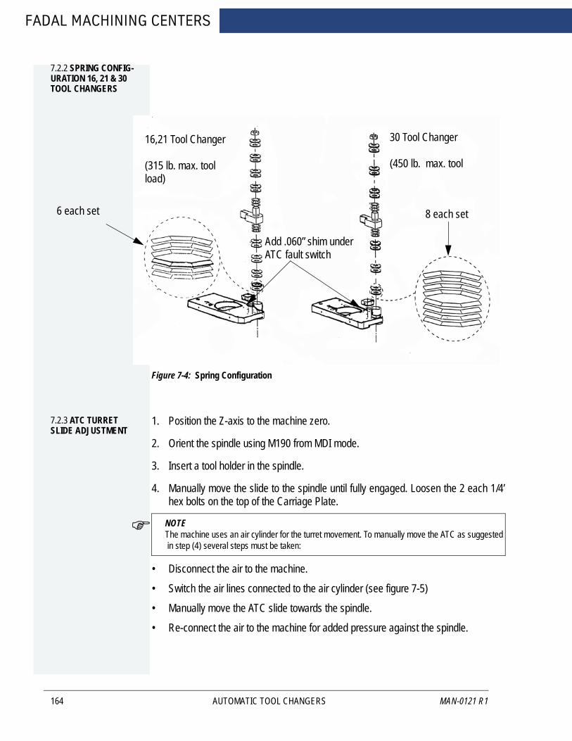
FADAL MACHINING CENTERS
7.2.2 SPRING CONFIG-URATION 16, 21 & 30 TOOL CHANGERS
164
Figure 7-4: Spring Configuration
8 each set
Add .060” shim under ATC fault switch
16,21 Tool Changer
(315 lb. max. tool load)
30 Tool Changer
(450 lb. max. tool
6 each set
7.2.3 ATC TURRET SLIDE ADJUSTMENT
1. Position the Z-axis to the machine zero.
2. Orient the spindle using M190 from MDI mode.
3. Insert a tool holder in the spindle.
4. Manually move the slide to the spindle until fully engaged. Loosen the 2 each 1/4’hex bolts on the top of the Carriage Plate.
NOTE The machine uses an air cylinder for the turret movement. To manually move the ATC as suggested in step (4) several steps must be taken:
• Disconnect the air to the machine.
• Switch the air lines connected to the air cylinder (see figure 7-5)
• Manually move the ATC slide towards the spindle.
• Re-connect the air to the machine for added pressure against the spindle.
AUTOMATIC TOOL CHANGERS
MAN-0121 R1
AUGUST 2005
FANUC MAINTENANCE MANUAL
Figure 7-5: Loosen Hex Bolts / Move Slide to Spindle Until Engaged
Figure 7-6: ATC Cylinder
5. Give the slide a firm push toward the spindle. Retighten the 2 bolts.
6. If the slide does not fully engage, loosen each of the six 3/8" hex bolts holding thetool carrier. This will allow the slide to fully engage.
Figure 7-7: Loosen Hex Bolts Holding Tool Carrier
Air lines to switch for ATC adjustmentAdjust the air flowAdjust the cushion
Adjust the cushion
AUTOMA
TIC TOOL CHANGERS 165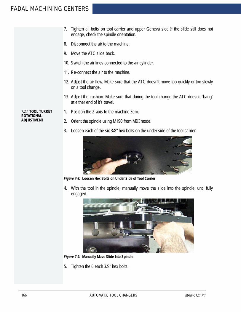
FADAL MACHINING CENTERS
166
7. Tighten all bolts on tool carrier and upper Geneva slot. If the slide still does notengage, check the spindle orientation.
8. Disconnect the air to the machine.
9. Move the ATC slide back.
10. Switch the air lines connected to the air cylinder.
11. Re-connect the air to the machine.
12. Adjust the air flow. Make sure that the ATC doesn’t move too quickly or too slowlyon a tool change.
13. Adjust the cushion. Make sure that during the tool change the ATC doesn’t “bang”at either end of it’s travel.
7.2.4 TOOL TURRET ROTATIONAL ADJUSTMENT
1. Position the Z-axis to the machine zero.
2. Orient the spindle using M190 from MDI mode.
3. Loosen each of the six 3/8" hex bolts on the under side of the tool carrier.
Figure 7-8: Loosen Hex Bolts on Under Side of Tool Carrier
4. With the tool in the spindle, manually move the slide into the spindle, until fullyengaged.
Figure 7-9: Manually Move Slide Into Spindle
5. Tighten the 6 each 3/8" hex bolts.
AUTOMATIC TOOL CHANGERS MAN-0121 R1

FANUC MAINTENANCE MANUAL
7.3 ATC MOTOR REPLACEMENT PROCEDURE
7.3.1 REPLACING THE TURRET MOTOR ON A GENEVA WHEEL ATC
AUGUST 2005
1. Remove the ATC cover.
2. Remove the Motor cover.
3. Disconnect the Molex connector with the motor wires.
4. Disconnect the ground wire.
5. Remove the four bolts holding the motor down.
6. Remove the motor.
7. Measure the distance from the bottom of the motor to the top of the Geneva gear.
8. Remove the Geneva gear.
9. Install Geneva gear on replacement motor at same position as on old motor.
10. Place motor in ATC and slide it firmly toward the Head.
11. Tighten motor mounting bolts.
12. Connect ground wire and Molex connector.
13. Perform alignment procedures.
14. Replace the covers.
AUTOMATIC TOOL CHANGERS 167
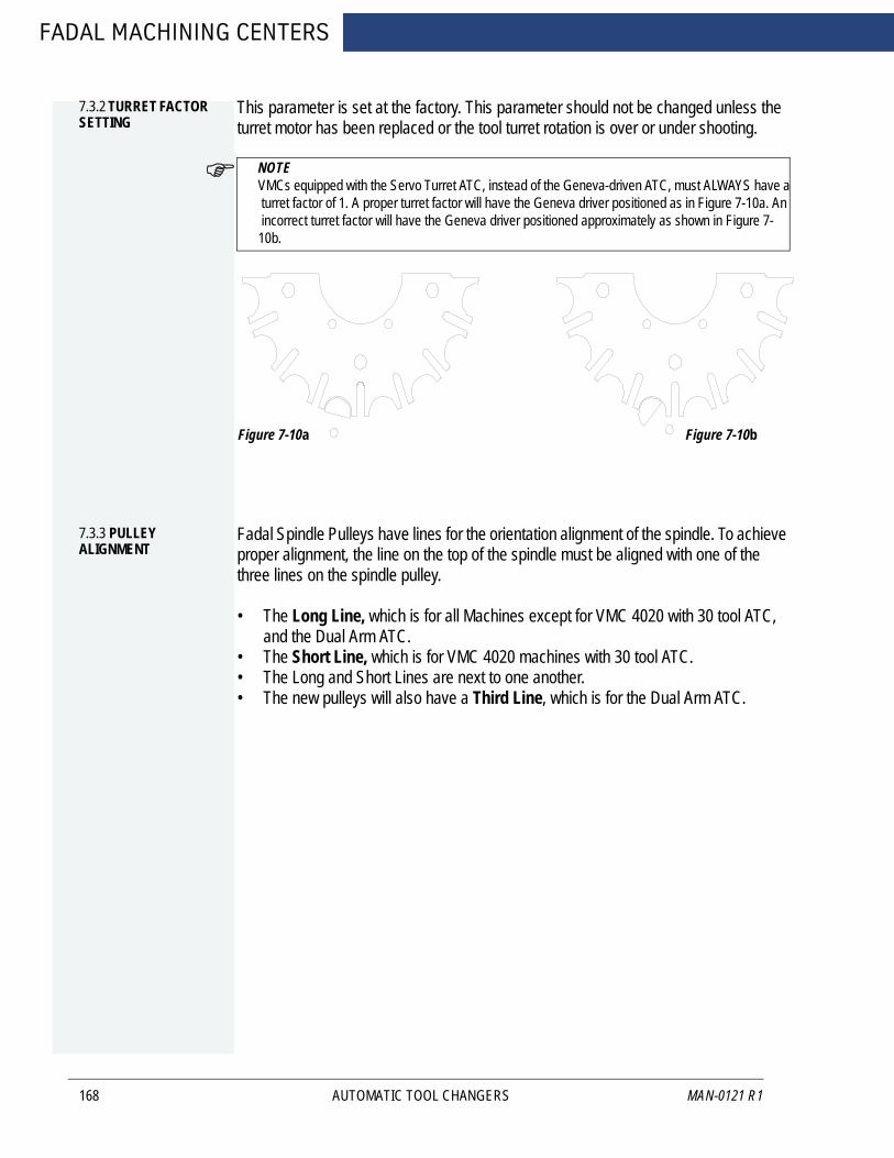
FADAL MACHINING CENTERS
7.3.2 TURRET FACTOR SETTING
168
This parameter is set at the factory. This parameter should not be changed unless the turret motor has been replaced or the tool turret rotation is over or under shooting.
NOTE VMCs equipped with the Servo Turret ATC, instead of the Geneva-driven ATC, must ALWAYS have a turret factor of 1. A proper turret factor will have the Geneva driver positioned as in Figure 7-10a. An incorrect turret factor will have the Geneva driver positioned approximately as shown in Figure 7-10b.
Figure 7-10a Figure 7-10b
7.3.3 PULLEY ALIGNMENT
Fadal Spindle Pulleys have lines for the orientation alignment of the spindle. To achieve proper alignment, the line on the top of the spindle must be aligned with one of the three lines on the spindle pulley.
• The Long Line, which is for all Machines except for VMC 4020 with 30 tool ATC, and the Dual Arm ATC.
• The Short Line, which is for VMC 4020 machines with 30 tool ATC.• The Long and Short Lines are next to one another.• The new pulleys will also have a Third Line, which is for the Dual Arm ATC.
AUTOMATIC TOOL CHANGERS
MAN-0121 R1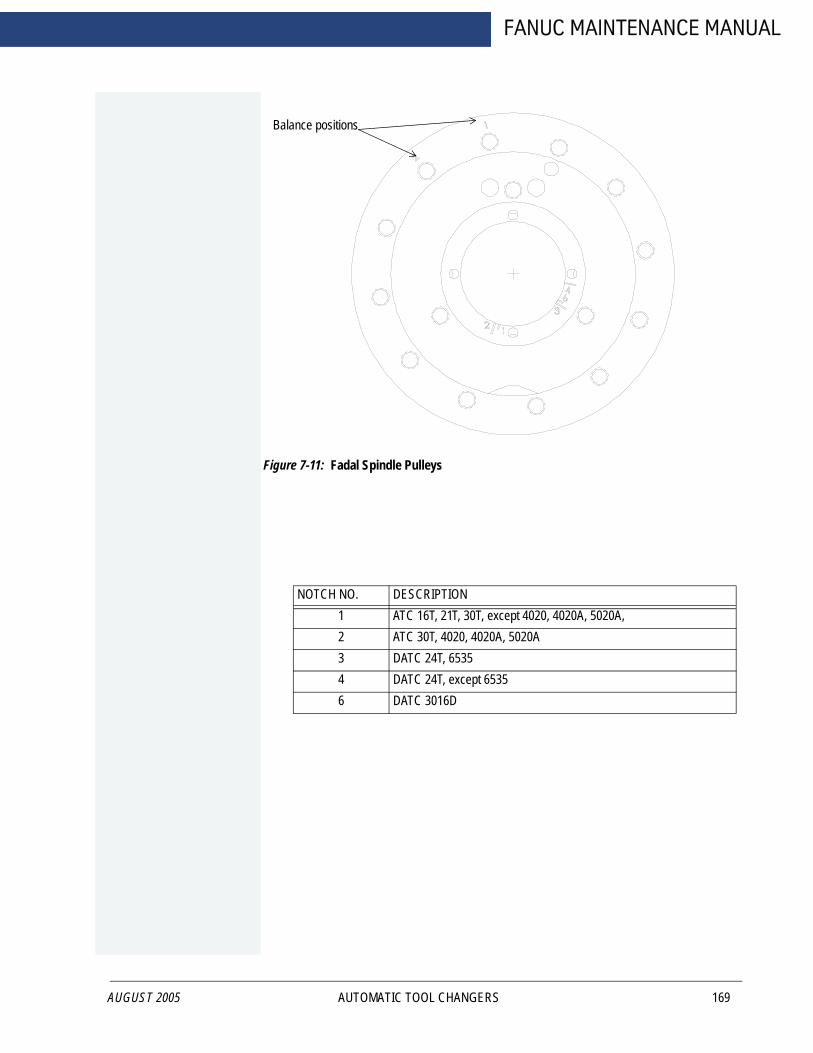
AUGUST 2005
FANUC MAINTENANCE MANUAL
Figure 7-11: Fadal Spindle Pulleys
NOTCH NO. DESCRIPTION1 ATC 16T, 21T, 30T, except 4020, 4020A, 5020A, 2 ATC 30T, 4020, 4020A, 5020A3 DATC 24T, 65354 DATC 24T, except 65356 DATC 3016D
Balance positions
AUTOMATIC TOOL CHANGERS 169

FADAL MACHINING CENTERS
7.4 DUAL ARM TOOL CHANGER
7.4.1 TOOL CHANGER SPECIFICATIONS
170
Table 7-1: DATC Tool Changer Specifications
SPECIFICATIONS 2216 3016 4020 6030 8030 4525 6535/40TType of Tool CAT-40/BT-40Number of Tools 20 24 21/62Maximum Tool Diameter
All Pockets Full 100mm (4in.)Adjacent Pockets Empty
180mm (7.2in.)
Maximum Tool Length 350mm (13.8in.)Tool Weight Maximum 6.5kg (14.3lbs.)
Average 5.0kg (11lbs.)Tool Magazine Drive Source
Motor Voltage 220VAC, 3 PhaseAir Pressure 5~7kg/sqcm (12.5psi)
AUTOMATIC TOOL CHANGERS MAN-0121 R1

FANUC MAINTENANCE MANUAL
7.4.2 SUB-ASSEM-BLIES
AUGUST 2005
Figure 7-12: Index Mechanism
Table 7-2: Index Mechanism
No. Part Description1 Cam Base2 Cylindrical Cam3 Sensor Block4 Proximity Switch Bracket5 Motor Base6 Driving Shaft7 Gear8 Gear Plate
2
AUTOMATIC TOOL CHANGERS 171

FADAL MACHINING CENTERS
172
Figure 7-13: Tool Arm
Table 7-3: Tool Arm
No. Part Description1 Tool Arm2 Tool Draw3 Tool Holding Rod4 Spring Cover5 Plunger6 Positioning Key7 Positioning Screw8 Self Lubricating Bearing9 Self Lubricating Bearing
10 Spring Pin
AUTOMATIC TOOL CHANGERS MAN-0121 R1

AUGUST 2005
FANUC MAINTENANCE MANUAL
Figure 7-14: Tool Falling Mechanism
Table 7-4: Tool Falling Mechanism
No. Part Description1 Tool Rod2 Sliding Block3 Sliding Block Cover Plate4 Positioning Block Stand5 Positioning Sliding Block (1)6 Positioning Sliding Block (2)7 Fixing Base of Tool Pot8 Positioning Sliding Block (3)
AUTOMATIC TOOL CHANGERS 173

FADAL MACHINING CENTERS
174
Figure 7-15: Tool Turret
Table 7-5: Tool Turret
No. Part Description1 Tool Magazine Motor2 Tool Magazine3 Tool Buckets
7.4.3 INSTALLATION & TESTING
Dual Arm ATC Installation and Alignment:
1. Verify that all bolts are properly tightened.
2. Remove the main cover surrounding the ATC arm and falling mechanism.
3. Remove the oil inlet plug and fill the ATC oil reservoir with lubricant (MOBIL DTEOIL HEAVY MEDIUM) to approximately 1-1/2 gallons or 5 liters. Observe the sightglass to verify that the oil reservoir does not over fill (see Figure 7-16, positions 1and 2). The alternative way to fill the oil reservoir is by utilizing the plugged air venton top and to the rear of the main ATC casting. This does not require the removal ofthe main cover.
NOTE Use caution during installation. Check all of the control elements for damage (sensors and wires).
AUTOMATIC TOOL CHANGERS MAN-0121 R1

AUGUST 2005
FANUC MAINTENANCE MANUAL
4. Install the ATC onto the machine using: 8 1/2 – 13 X 1 ¾ inch UNC-2B HHC hexcap screws with eight split lock washers.
5. Do not tighten the mount bolts completely. They will need to remain loose to allowfor the front to back and side to side alignments to be made.
6. Using a crane or forklift, position the ATC as needed to assist in the adjustments.
7. Install the alignment fixture to the spindle mount surface using two 3/8-16X1” bolts.Verify that the fixture is centered. Slowly tighten the fixture. Keep the fixturecentered throughout the procedure.
NOTE Before proceeding to the next step, review the applicable job sheet to confirm that the ATC is set-up for the specified tool holder configuration (CAT-40 or BT-40). The tool grippers and tool orientation (or positioning) keys may need to be changed if the tool holder configuration needs to be changed.
8. Remove the socket head cap screws plus the 2-8mm Roll pins mounting thegripper onto the ATC arm body (the gripper has 3 bolts for the 4525 and 4 for the3020 and 6535).
9. Install and tighten the gripper with the proper tool orientation (or position) key. SeeFigure 7-16:, positions 1, 6, and 7.
10. When manually rotating the tool arm, use the proper socket on top of the toolchanging mechanism motor shaft. The drill motor should turn forward or CW.
11. While rotating the ATC arm, pull the motor brake switch up. This is theelectromagnetic brake that will be holding the motor back from turning smoothly.The switch is located on top and to the front of the ATC motor (the switch must beheld up). See Figure 7-16:, position 3.
12. The ATC arm body will turn 80 degrees for the 3020, 65 degrees for the 4525 and35 degrees for the 6535. The tool falling mechanism will engage. The arm will thenmove down and turn 180 degrees, for both the 3020 and 4525, to exchange gripperpositions. Stop turning the motor when the arm reaches the down position.
13. With the falling mechanism in the down position, put the proper tool holder type inthe forward tool gripper and orient the tool so that it goes into the arm gripper withthe deepest relief engaging the gripper key way.
14. To install the tool holder manually, it will be necessary to push the plungermechanism down, to release the pressure of the tool holding rod. See Figure 7-16:,positions 2 and 3.
15. Begin manually turning the motor of the ATC. The falling mechanism will startmoving back up. Stop turning the motor when the arm reaches the top mostposition or has reached the dead spot, before changing direction.
AUTOMATIC TOOL CHANGERS 175

FADAL MACHINING CENTERS
176
16. JOG the Z-axis down and position the head and spindle fixture at or near thenormal Z-axis cold start position. this will put the tool holder up inside the fixture. Donot allow the sides of the tool holder to touch the Inner Diameter (I.D.) of thespindle fixture.
17. If the ATC is off alignment, adjust the front to back and side to side as needed, untilthe tool can be inserted into the spindle fixture to a minimum of 1”.
18. Put a small level on the ATC arm body to check the level. Typically, this would bethe same level adjustment as the base casting. Check the base way, with the smalllevel, as the reference position.
19. With a dial-caliper (Veiner-Caliper) or a depth micrometer, check the distance fromthe outer diameter (O.D.) of the tool holder to the O.D. of the spindle fixture usingthe fixture through holes. Split the difference between the front to back readings.
20. Check the distance between the O.D. of the tool holder to the O.D. of the spindlefixture, using the through holes, and split the difference between the side to sidereadings. See Figure 7-16, positions 4, 5, 6 and 7.
21. The reading that was obtained in step #20 will be the shim size required.
22. If required, install the shims in groups of twos, one along the top the row of the ATCmount bolts and one underneath the bottom row of mount bolts. See Figure 7-17:,positions 4,5, and 6.
23. With a forklift or crane still connected to the ATC, loosen the support bolts toreposition the ATC. Using a rubber mallet, shift the tool changer forward orbackward, or bring the front up or down. The forward and backward movement ofthe ATC is used to adjust the horizontal straightness. The front of the tool changerbeing moved up or down is used to adjust the level.
24. To properly adjust the side to side position of the ATC, use one of the followingmethods:
a. Remove one of the shims from in between the main casting and the extendedmount bracket. These items were used to compensate for dimension toler-ances that resulted from the manufacturing process. Shims may or may not bepresent.
b. Remove the ATC extension mount bracket and mill it down to the properdimension and then reassemble the part to the machine (This is only in thecase of not having shims present between the ATC and extension bracket).
c. Manufacture shims that will be inserted between the extended mount bracketand the column casting of the machine. Loosen the support bolts to allow theshims to be inserted in along the top and bottom rows of the ATC mountbracket, at the column.
AUTOMATIC TOOL CHANGERS MAN-0121 R1

AUGUST 2005
FANUC MAINTENANCE MANUAL
25. Recheck the level and alignment of the ATC for front to back and side to side. Ifnecessary, re-adjust the alignment and tighten the ATC into position. See Figure 7-18:.
26. Repeat above steps for the opposite tool gripper to ensure consistent alignmentbefore pinning the ATC into its final position.
27. Drill and ream the four dowel-pin holes to accept tapered pins. The drill size is5.953mm. The tapered Reamer size is: #5
NOTE When reaming the holes for the dowel pins, observe that the pins do not extend past the edge of the hole by more than 6.35mm (1/4 in.).
28. Install four #5 tapered dowel-pins into the ATC arm mount at the column. SeeFigure 7-16:, position 4.
29. Switch to the reverse direction on the drill motor to manually rotate the tool armback, so the tool holder can be removed.
30. While rotating the ATC arm, pull the motor brake switch up. This is theelectromagnetic brake that will be holding the motor back from turning smoothly.The switch is located on top and to the front of the ATC motor (the switch must beheld up). See Figure 7-16:, position 3. When the motor has reached the lowestposition, press the plunger and remove the tool holder.
31. Start turning the ATC motor again, in the same direction as in step #30. The fallingmechanism will reverse, sending the arm back up. At the highest position, the armbody will turn back (80 degrees for the 3020, 65 degrees for the 4525 and 35degrees for the 6535) to the stand by position 1 (ATC Home Position).
AUTOMATIC TOOL CHANGERS 177

FADAL MACHINING CENTERS
178
32. Remove the spindle fixture from the head.
Figure 7-16: Manual Rotation of Tool Arm
Figure 7-17: Pull Motor Brake Switch
AUTOMATIC TOOL CHANGERS MAN-0121 R1
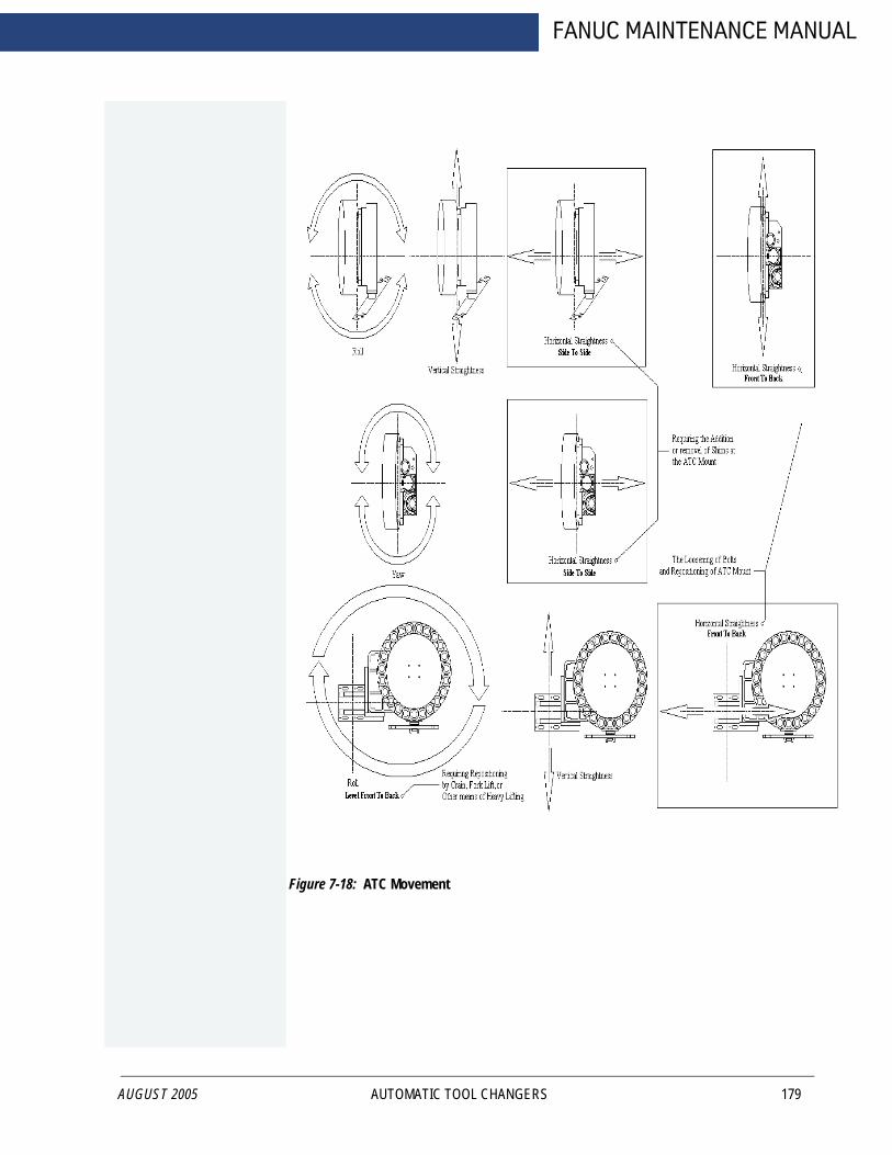
AUGUST 2005
FANUC MAINTENANCE MANUAL
Figure 7-18: ATC Movement
AUTOMATIC TOOL CHANGERS 179

FADAL MACHINING CENTERS
180
Figure 7-19: Engage Gripper Key Way
7.4.4 SCHEDULED MAINTENANCE
The maintenance schedule is based on machine usage of eight hours a day, five days a week.
Daily Maintenance
Perform the following daily:
1. Cleaning
a. Remove the chips and debris surrounding the proximity switch inducing block.
AUTOMATIC TOOL CHANGERS MAN-0121 R1

AUGUST 2005
FANUC MAINTENANCE MANUAL
b. Remove the chips and debris that have accumulated on the inverted movingbody of the tool pot.
c. Clear the tool changing mechanism of all debris before any operation.
2. Inspection:
a. Check the parts of the tool falling mechanism for damage and wear. Addgrease to the sliding base of the tool falling mechanism and the pull rod.
b. Check the parts of the tool pots, tool discs, and snap rings for damage andtightness.
Weekly Maintenance
Perform the following weekly:
1. Greasing:
a. Grease the claws of the tool changing arm unit.b. Grease the tip of the release pin of the tool changing unit.
Miscellaneous Maintenance
Perform the following as necessary:
1. Change the lubricant annually or as needed. The recommended lubricant is SAE90-140. The Dual Arm Tool Changer uses approximately 5 liters (1.3 gallons).
AUTOMATIC TOOL CHANGERS 181

FADAL MACHINING CENTERS
7.5 DATC TOOL CHANGER ADJUSTMENT PROCEDURE
182
***Verify the cold start position.
****First, should finish the M84 spindle belt calibration and spindle orientation setup before setup the tool changer.
***Preparation: Verity the spindle orientation using M190.
Follow the next adjustment procedure:
1. Turn on the special keep relay to active related function manually to adjust the tool changer.
2. Change to MDI mode.
3. Press Parameter key, then press PMC soft key, select PMC PRM, then press KEEPRLY menu.
K30 Keep Relays are provided for Fadal manufacturing and Fadal factory & authorized service. Relays are provided to enable manual operation of machine functions. Due to requirements when used for service, normal interlocking of machine mechanisms are not enforced. Use with extreme caution. Operator message indicating “setup mode” is
K0030 0 0 0 0 0 0 0 0 00
K0030.0 Bypass Z axis Tool Changer Location Switch (Fadal Assembly Floor Use Only)
Bypass = 1 Normal = 0
K0030.1 Bypass Door Open Switch (Fadal Assembly Floor Use Only)
Bypass = 1 Normal = 0
K0030.2K0030.3 Force Spindle Air On (Y8.6)
(Fadal Assembly Floor Use Only)Force = 1 Normal = 0
K0030.4 Force Spindle Draw Bar Open (Y8.5) (Fadal Assembly Floor Use Only)
Force = 1 Normal = 0
K0030.5 Manual Index (Up/Down) of DATC Tool Drum Pot (Fadal Assembly Floor Use Only)
Enable = 1 Normal = 0
K0030.6 Manual Toggle In/Out of Tool Change Orient Arm (Fadal Maintenance Use Only)
Enable = 1 Normal = 0
K0030.7 Manual Jog of Tool Arm (Fadal Maintenance Use Only)
Enable = 1 Normal = 0
AUTOMATIC TOOL CHANGERS MAN-0121 R1
AUGUST 2005
FANUC MAINTENANCE MANUAL
active displayed when any Keep Relays are set to “1”. All settings are always to be set to “0” for use of machine by Auto/MDI commands.
K0030.0 Z axis Tool Changer Position Proximity Switch
Bypass door open proximity switch. Intended for factory assembly use only, prior to sheet metal and Z axis position switch mounting.
K0030.1 Ignore Door Open Switch
Bypass door open proximity switch. Intended for factory assembly use only, prior to sheet metal and door switch mounting.
K0030.3 Turn On Spindle Air for Service
Turn on output Y8.6 for spindle air pressure.
K0030.4 Turn On Spindle Draw Bar
Turn on output Y8.5 for spindle draw bar.
K0030.5 Manual Index (Up/Down) of DATC Tool Drum Pot
Enable manual, command of bottom tool pot in tool carousel. Must be in Incr Jog mode. Use 1KX pushbutton for tool down motion, 100X pushbutton for tool up motion. use with extreme caution. Intended for use by setup/maintenance work only.
K0030.6 Manual Toggle In/Out of Tool Change Orient Arm
Enable manual activation of tool change orient locking arm for maintenance work. Must be in Jog mode. Use 10X pushbuttom to toggle locking arm In/Out. Use with extreme caution.
K0030.7 Manual Jog of Tool Arm
Enable manual rotation of tool change dual swing arm for machine setup/maintenance work. Must be in Jog mode. Use 1KX pushbutton for forward rotation, 100X pushbutton for reverse rotation. Please use with extreme caution. Remove tool from spindle before using. Draw bar will not release if tool in spindle is grabbed by tool arm.
4. Check the K bit according the DATC tool changer
K5.3=1-- DATC 20K5.4=1-- DATC 24K5.5=1-- DATC 32K5.6=1-- DATC 62
AUTOMATIC TOOL CHANGERS 183

FADAL MACHINING CENTERS
184
K5.7=1-- DATC 40
5. Spindle Orientation M code
M190
AUTOMATIC TOOL CHANGERS MAN-0121 R1
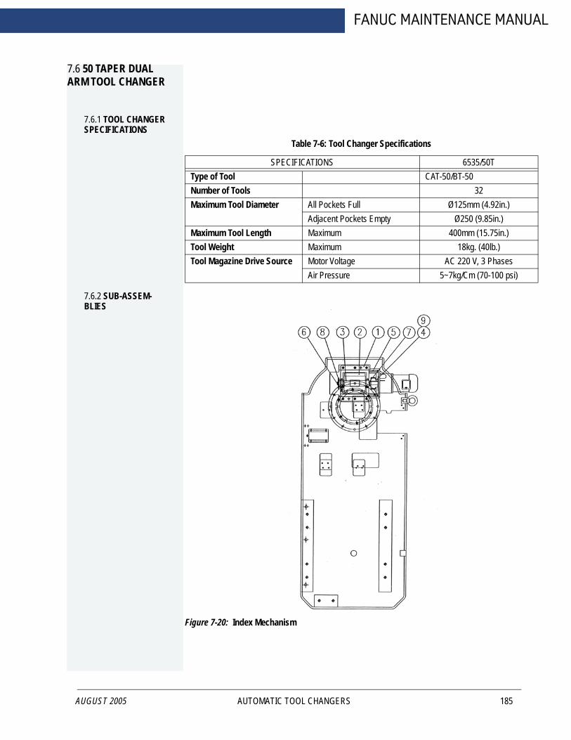
FANUC MAINTENANCE MANUAL
7.6 50 TAPER DUAL ARM TOOL CHANGER
7.6.1 TOOL CHANGER SPECIFICATIONS
AUGUST 2005
Table 7-6: Tool Changer Specifications
SPECIFICATIONS 6535/50TType of Tool CAT-50/BT-50Number of Tools 32Maximum Tool Diameter All Pockets Full Ø125mm (4.92in.)
Adjacent Pockets Empty Ø250 (9.85in.)Maximum Tool Length Maximum 400mm (15.75in.)Tool Weight Maximum 18kg. (40lb.)Tool Magazine Drive Source Motor Voltage AC 220 V, 3 Phases
Air Pressure 5~7kg/Cm (70-100 psi)
7.6.2 SUB-ASSEM-BLIES
Figure 7-20: Index Mechanism
AUTOMATIC TOOL CHANGERS 185

FADAL MACHINING CENTERS
186
Figure 7-21: 50 Taper Tool Arm
Table 7-7: Index Mechanism
No. Part Description1 Cam Base2 Cylindrical Cam3 Driving Spindle4 Gear5 Motor Base6 Proximity Switch Base7 Gear’s Locking Basket8 Proximity Switch Block9 Gear
AUTOMATIC TOOL CHANGERS MAN-0121 R1
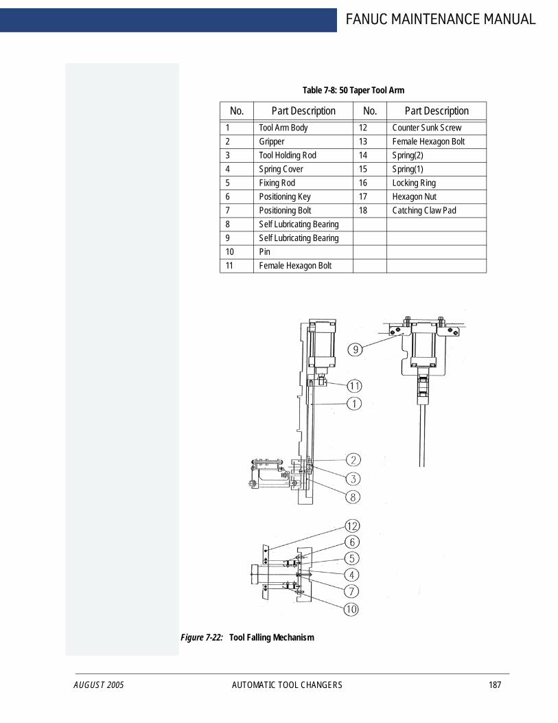
AUGUST 2005
FANUC MAINTENANCE MANUAL
Figure 7-22: Tool Falling Mechanism
Table 7-8: 50 Taper Tool Arm
No. Part Description No. Part Description1 Tool Arm Body 12 Counter Sunk Screw2 Gripper 13 Female Hexagon Bolt3 Tool Holding Rod 14 Spring(2)4 Spring Cover 15 Spring(1)5 Fixing Rod 16 Locking Ring6 Positioning Key 17 Hexagon Nut7 Positioning Bolt 18 Catching Claw Pad8 Self Lubricating Bearing9 Self Lubricating Bearing10 Pin11 Female Hexagon Bolt
AUTOMATIC TOOL CHANGERS 187

FADAL MACHINING CENTERS
188
Table 7-9: Tool Falling Mechanism
No. Part Description No. Part Description1 Tool Falling Pull Rod 9 Cylinder Base 2 Sliding Block 10 Positioning Slide Block 3 Sliding Block Cover Plate 11 Connecting Block4 Positioning Block 12 R-Fixing Plate 5 Positioning Sliding Block (1)6 Positioning Sliding Block (2)7 Pot Fixing Base8 Positioning Block
AUTOMATIC TOOL CHANGERS MAN-0121 R1

AUGUST 2005
FANUC MAINTENANCE MANUAL
Figure 7-23: Control Elements
Table 7-10: Control Elements
No. Part Description1 Tool Changing Mechanism
Motor2 Index Mechanism Motor3 Proximity Switch 14 Reed Switch 2
AUTOMATIC TOOL CHANGERS 189

FADAL MACHINING CENTERS
190
Table 7-10: (Continued) Control Elements
No. Part Description5 Reed Switch 16 Proximity Switch 27 Proximity Switch 38 Proximity Switch 49 Proximity Switch 410 Control Box
7.6.3 INSTALLATION
1. Check if all the bolts and parts are affixed tightly (they might be loose duringtransportation). If not; fasten them tightly.2. Check if the automatic tool changer has any interference with the column ofmachining center or other area while connecting to the interface.
3. Check voltage specification of motors, sensors and wiring condition to see if theyare all compatible with the control system of the machining center.
4. Insure that the conducting wire of control elements during installation is notdamaged.
5. Install the automatic tool changer with the machining center, adjusting the relativeposition between the tool arm and spindle.
a. When manually rotating the tool arm for the proper angle, put the wrench onthe top of the tool changing mechanism motor shaft to rotate the arm.
b. While rotating the arm, pull rod of the motor brake must be released for smoothrotation.
c. Adjust the shaft of the arm and spindle in the vertical direction so that they areparallel.
6. Connect each control element according to the diagrams with the relative points ofthe machining center.
7. When programming the automatic tool changer, note the protection programmingbetween each single action and refer to ‘SEQUENCE OF ELECTRIC ACTIONS'and ‘INSTALLATION NOTICE.’
8. Check all the wiring and the relative connections to see if they are accurate beforetrial running.
9. When performing the trial running, take single action in the beginning, then go forsuccessive actions.
AUTOMATIC TOOL CHANGERS MAN-0121 R1

AUGUST 2005
FANUC MAINTENANCE MANUAL
10. If the trial running of single action is not smooth, stop running to check, in order toavoid any damage.
11. If it is necessary, prolong the time between each related action.
12. When performing the successive running, be careful not to miss any interlockprotection programming between all the relative actions.
7.6.4 INSTALLATION NOTICE
1. Make the necessary interlock protection programming for all the relativeconnections. The following chart is for reference.
2. After the tool falling of the tool pot is completed, there must be little prolonged time(0.10.25 seconds) before the tool catching of arm. The purpose is to have sufficientair pressure inside the cylinder to avoid shaking of the tool pot while tool catching.
3. After the sensor of the tool unclamping or the tool clamping of the spindle claw issensed, there could be some prolonged time if necessary. If the tool arm isproceeding the next action before the tool has been unclamped or clampedcompletely from spindle claw, tool might be forced to be pulled out or the tool mightbe falling.
4. Adjust the pressure of cylinder to be 5-7 kg/c m².
Table 7-11: Interlock Protection Programming
Relay Control Tool Disk
Rotation
Tool Falling
Tool Returning
Tool Changing Mechanism
ActionTool Disc Starting Off Off OffReed switch of tool returning(protruding of cylinder)
On
Reed switch of tool returning(protruding of cylinder)
On
Proximity switch of tool count-ing and positioning of tool disk
On On On
Relay of tool changing mecha-nism motor starting
Off Off
Proximity switch of origin of tool changing mechanism
On On
AUTOMATIC TOOL CHANGERS 191

FADAL MACHINING CENTERS
7.6.5 TROUBLESHOOTING
192
Table 7-12: Troubleshooting
SYMPTOM POSSIBLE REASONS SOLUTIONTool disk is not rotating while tool selecting
1) Proximity switch of tool counting and positioning of tool disc is not sensed
2) Proximity switch is out of order
3) Index mechanism motor is out of order
4) Motor brake is out of order 5) Reed switch of tool
returning (protruding of cylinder) is not at the proper position
1) Adjust the proximity switch to the proper position
2) Change a new proximity switch
3) Repair the motor or change a new one
4) Check the wiring or change its parts
5) Adjust it to the proper position
Tool disc does not stop at locat-ing position
1) Brake of index mechanism motor is not working
2) Distance between proximity switch of tool counting & positioning of tool disc and inducing block is too long
3) Proximity switch is out of order
1) Check if wiring of brake is correct or if its parts are out of order
2) Adjust the distance between proximity switch and inducing block to be closer
3) Change a new proximity switch
Tool disc keeps Rotating 1) Distance between proximity switch of tool counting & positioning of tool disc and inducing block is too long
2) Proximity switch is out of order
1) Adjust the distance between proximity switch and inducing block to be closer
2) Change a new proximity switch
Fixing base of tool pot is deformed
Tool disc rotates while tool pot is falling
Change a new set of fixing base, and adjust, then put spring in
Tool disc is stuck while rotating 1) "C" snap ring is loose, or parts of tool pot fixing base are falling apart
2) Cylinder works while tool disc is rotating, so tool pot is stuck at tool falling position
1) Disassemble the scattered fixing base and check each part if they are all workable of change a new set of fixing base
2) Check if the tool pot fixing base is deformed. Put sliding block of tool falling and roller back if they are falling apart
Tool pot is shaking while tool returning or tool falling.
1) Sliding base of tool falling is not lubricated enough
2) Speed of cylinder is not even
1) Apply grease2) Adjust intake pressure and
speed adjusting device of cylinder
Tool pot is not at locating posi-tion while tool falling or tool returning
Blots of pull rod of tool falling are loose
Adjust bolts of pull rod of tool falling to be normal and tighten them
AUTOMATIC TOOL CHANGERS MAN-0121 R1
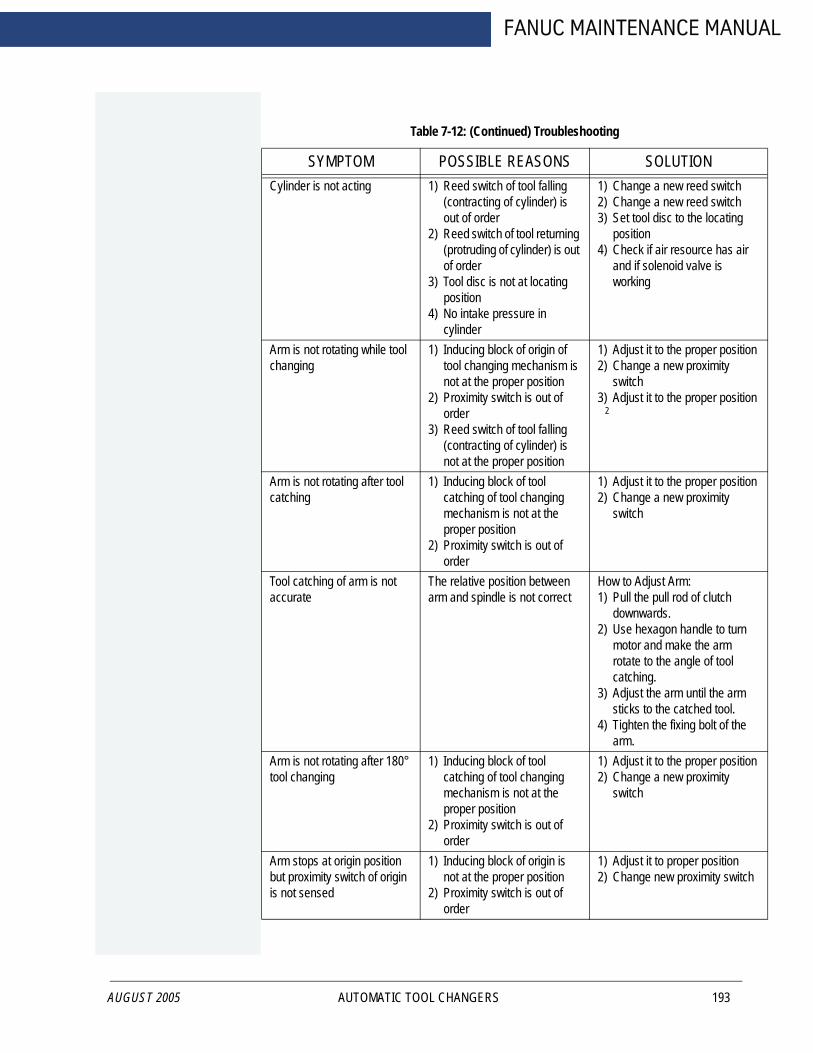
AUGUST 2005
FANUC MAINTENANCE MANUAL
Table 7-12: (Continued) Troubleshooting
SYMPTOM POSSIBLE REASONS SOLUTIONCylinder is not acting 1) Reed switch of tool falling
(contracting of cylinder) is out of order
2) Reed switch of tool returning (protruding of cylinder) is out of order
3) Tool disc is not at locating position
4) No intake pressure in cylinder
1) Change a new reed switch2) Change a new reed switch3) Set tool disc to the locating
position4) Check if air resource has air
and if solenoid valve is working
Arm is not rotating while tool changing
1) Inducing block of origin of tool changing mechanism is not at the proper position
2) Proximity switch is out of order
3) Reed switch of tool falling (contracting of cylinder) is not at the proper position
1) Adjust it to the proper position2) Change a new proximity
switch3) Adjust it to the proper position
Arm is not rotating after tool catching
1) Inducing block of tool catching of tool changing mechanism is not at the proper position
2) Proximity switch is out of order
1) Adjust it to the proper position2) Change a new proximity
switch
Tool catching of arm is not accurate
The relative position between arm and spindle is not correct
How to Adjust Arm:1) Pull the pull rod of clutch
downwards.2) Use hexagon handle to turn
motor and make the arm rotate to the angle of tool catching.
3) Adjust the arm until the arm sticks to the catched tool.
4) Tighten the fixing bolt of the arm.
Arm is not rotating after 180° tool changing
1) Inducing block of tool catching of tool changing mechanism is not at the proper position
2) Proximity switch is out of order
1) Adjust it to the proper position2) Change a new proximity
switch
Arm stops at origin position but proximity switch of origin is not sensed
1) Inducing block of origin is not at the proper position
2) Proximity switch is out of order
1) Adjust it to proper position2) Change new proximity switch
2
AUTOMATIC TOOL CHANGERS 193

FADAL MACHINING CENTERS
194
Arm is supposed to stop at origin position but is not accurate
Inducing blocks are not at the proper position
Turn the 3 inducing blocks simul-taneously to the proper angle
Motor is too hot 1) Brake is not released2) Brake is out of order3) Commutator is out of order
1) Check commutator is with electricity or not
2) Repair the brake or change to a new one
3) Change a new commutatorTiming belt of tool changing mechanism is sliding frompulley
1) The timing belt is too loose 2) The timing belt is worn
1) Adjust timing belt tight2) Change a new timing belt
Table 7-12: (Continued) Troubleshooting
SYMPTOM POSSIBLE REASONS SOLUTION
7.6.6 MAINTENANCE
1. The lubricant inside the lubricant container of the tool changing mechanism shouldbe changed after working for 2400 hours.When the cam, rollers and the bevel gear are in use without lubricant, abnormal wear and fractures will occur. Appropriate quantity of lubricant should be a little more than half of the lubricant container.
2. Change of lubricant
The lubricant should be changed annually or when the lubricant becomes worse. Recommended lubricants viscosity: SAE 90140. Amount of lubricant: 5L.
3. Apply grease weekly
a. On the grippers of tool arm b. On the tip of tool holding rod of tool arm c. On the sliding block of tool falling, fixing base of pull rod of tool falling
4. Cleaning
a. Remove the chips around all the proximity switches and reed switches. b. Remove the chips inside the tool pot. c. The tool changing mechanism parts should be cleaned frequently so that the
chips will not stick to it.
5. Check the tool falling mechanism parts regularly.
6. Check the parts of tool pots & tool disc and also check if "C" snap rings are tightregularly. If not, fasten them tightly or change new parts.
AUTOMATIC TOOL CHANGERS MAN-0121 R1
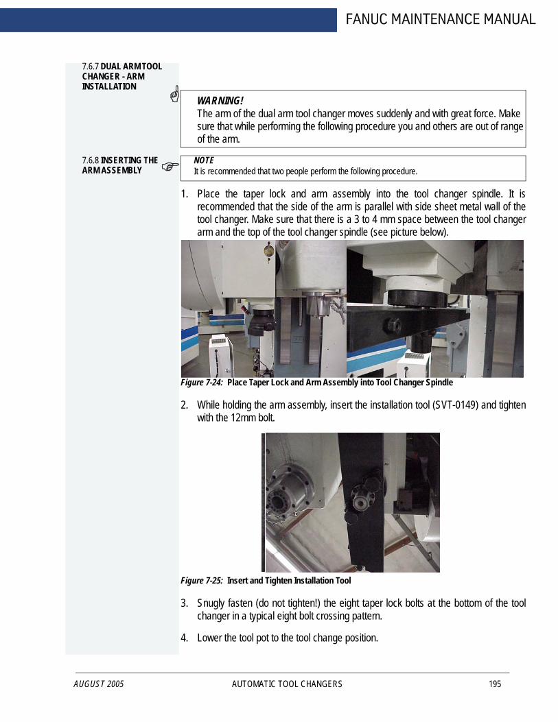
FANUC MAINTENANCE MANUAL
7.6.7 DUAL ARM TOOL CHANGER - ARM INSTALLATION
AUGUST 2005
WARNING!The arm of the dual arm tool changer moves suddenly and with great force. Make sure that while performing the following procedure you and others are out of range of the arm.
7.6.8 INSERTING THE ARM ASSEMBLY
NOTE It is recommended that two people perform the following procedure.
1. Place the taper lock and arm assembly into the tool changer spindle. It isrecommended that the side of the arm is parallel with side sheet metal wall of thetool changer. Make sure that there is a 3 to 4 mm space between the tool changerarm and the top of the tool changer spindle (see picture below).
Figure 7-24: Place Taper Lock and Arm Assembly into Tool Changer Spindle
2. While holding the arm assembly, insert the installation tool (SVT-0149) and tightenwith the 12mm bolt.
Figure 7-25: Insert and Tighten Installation Tool
3. Snugly fasten (do not tighten!) the eight taper lock bolts at the bottom of the toolchanger in a typical eight bolt crossing pattern.
4. Lower the tool pot to the tool change position.
AUTOMATIC TOOL CHANGERS 195

FADAL MACHINING CENTERS
196
5. Insert a tool holder into the spindle and the lowered tool pot.
6. Jog the Z axis to correct tool change position.
7. Lock the spindle with the M190 command.
8. Again enter the Dual Arm Tool Changer Menu and select number 4 (Move ArmReverse) or 3 (Move Arm Forward) to slowly bring the arm into both tool holders.
9. Use your hands to push the tool changer arm into both tool holders making surethat both tool holders are gripped entirely by the tool changer arm.
10. Tighten the eight taper lock bolts at the bottom of the tool changer in a typical eightbolt crossing pattern.
11. Remove the installation tool (SVT-0149).
7.6.9 DUAL ARM TOOL CHANGER ALIGNMENT
1. Remove the dual arm head position sensor and replace with Jumper ELE-0088.
2. Lock the spindle with the M190 command.
3. Jog the Z axis up.
AUTOMATIC TOOL CHANGERS MAN-0121 R1
FANUC MAINTENANCE MANUAL
AUGUST 2005
8.0 AXES DRIVE SYSTEM
AXES DRIVE SYSTEM 197

FADAL MACHINING CENTERS
8.1 ROTARY TABLES, 4TH AXIS
198
Figure 8-1: Rotary Table
8.1.1 PRE-INSTALLA-TION
Remove the top of the shipping crate:
1. With a large screwdriver gently pry the clips from the bottom of the crate.
2. Remove the crate top.
Install all items except the Rotary Table itself. These items are included specifically for your VMC configuration, and may include:
Amplifier Servo Card
Axis Controller Card
Brake Solenoid
Overload Relay
Air Lines and Fittings
Prewire Harness
AXES DRIVE SYSTEM MAN-0121 R1
FANUC MAINTENANCE MANUAL
8.1.2 REMOVE THE ROTARY TABLE FROM THE SHIPPING CRATE
AUGUST 2005
WARNING!Wear Safety goggles, steel toe shoes and gloves to reduce the risk of injury.The VMC table, or any surface on which the rotary table rests, must be free of chips, or anything else that might damage it.
1. Loosen 3/8-16 bolts securing the rotary table and/or tail stock to the crate.
2. Using proper lifting procedures to reduce the risk of muscle strain. Remove therotary table and/or tail stock.
3. Save the shipping crate. It will be needed if the rotary table needs to be returned toFADAL for any reason.
8.1.3 INSTALLATION
1. Stone both the table and the bottom surface of the rotary table to remove anypossible dings. Wipe clean with a light oil.2. Jog the VMC’s table to the X+ and Y+ limits to ease installation. The rotary tablenormally sits on the right side of the VMC table.
3. Using proper lifting procedures, position the rotary table above the VMC’s center Tslot, and attach the supplied table keys with two 1/4-20 x 3/4 socket head capscrews.
4. Secure the rotary table to the table using two 1/2-13 x 1 3/4 hex head bolts andhard washers with two 1/2-13 T-nuts. DO NOT TORQUE BOLTS UNTIL THEROTARY TABLE IS SQUARE.
8.1.4 SQUARING THE VH-65
1. Place a tool holder with indicator in the VMC spindle.
2. Square the rotary table at the face plate surface using a soft-face mallet, andtighten the 1/2-13 bolts when square.
8.1.5 SETTING THE VH-65 WORM GEAR BACKLASH
After disassembly or repairs, set the mechanical backlash for the VH-65 as follows:
NOTE Setting the backlash requires a granite plate or other precision surface.
AXES DRIVE SYSTEM 199

FADAL MACHINING CENTERS
200
1. The Higgins nut pre-load should be no more than hand tight.
Figure 8-2: Higgins Nut
2. Secure the Higgins nut to the worm shaft by tightening the set screw.
Figure 8-3: Tighten Set Screw
Higgins Nut
AXES DRIVE SYSTEM MAN-0121 R1

AUGUST 2005
FANUC MAINTENANCE MANUAL
3. The bolts holding the worm pivot plate must be loose to allow setup for theadjustments.
Figure 8-4: Loosen Bolts Holding Worm Pivot Plate
4. The pivot adjustment screws should be set to zero (pivot plate resting on pin A)before starting the adjustment procedure.
Figure 8-5: Set Pivot Adjustment Screws to Zero
A
AXES DRIVE SYSTEM 201

FADAL MACHINING CENTERS
202
5. Turn the top pivot adjusting screw one turn on the side opposite of the motor. Turnthe screw on the motor side two turns. (A turn for this procedure is as far as thewrench will move from one side of the pocket to the opposite side).
Figure 8-6: Turn Top Pivot Adjusting Screw and Screw on Motor Side
6. Set an indicator on a stand. Zero the indicator on the worm pivot plate of the sideopposite the motor.
Figure 8-7: Zero Indicator on Worm Pivot Plate
AXES DRIVE SYSTEM MAN-0121 R1
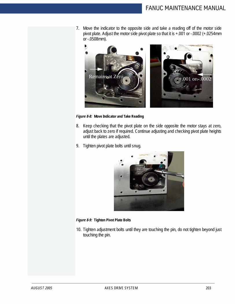
AUGUST 2005
FANUC MAINTENANCE MANUAL
7. Move the indicator to the opposite side and take a reading off of the motor sidepivot plate. Adjust the motor side pivot plate so that it is +.001 or -.0002 (+.0254mmor -.0508mm).
Figure 8-8: Move Indicator and Take Reading
8. Keep checking that the pivot plate on the side opposite the motor stays at zero,adjust back to zero if required. Continue adjusting and checking pivot plate heightsuntil the plates are adjusted.
9. Tighten pivot plate bolts until snug.
Figure 8-9: Tighten Pivot Plate Bolts
10. Tighten adjustment bolts until they are touching the pin, do not tighten beyond justtouching the pin.
Remains at Zero +.001 or -.0002
AXES DRIVE SYSTEM 203

FADAL MACHINING CENTERS
204
11. Install motor plate o-ring and set motor on housing with two bolts at oppositecorners.
Figure 8-10: Install Motor Plate O-Ring and Set on Housing
12. Connect power leads to the motor.
13. Listen to the operation of worm gear. Any knocking or banging indicates a bad gearadjustment on the worm or motor gear. Exit the program and enter the JOG mode.
14. Place an indicator on the face of the chuck, near the outer edge of the chuck asshown.
Figure 8-11: Place Indicator on Face of Chuck
15. Zero the indicator and jog the axis in each direction returning to the initial position.The indicator should not be more than +/- .0001” (0.0508mm) from zero. If theindication exceeds this, continue with the next step to determine the cause ofbacklash error.
AXES DRIVE SYSTEM MAN-0121 R1
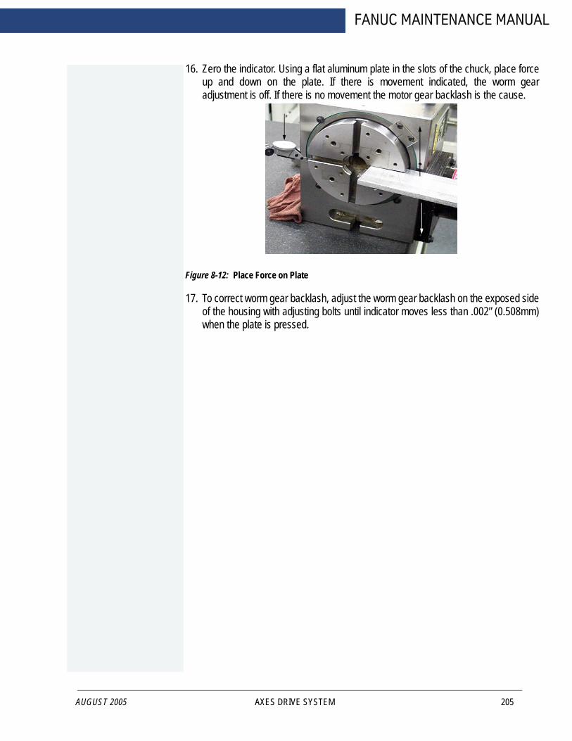
AUGUST 2005
FANUC MAINTENANCE MANUAL
16. Zero the indicator. Using a flat aluminum plate in the slots of the chuck, place forceup and down on the plate. If there is movement indicated, the worm gearadjustment is off. If there is no movement the motor gear backlash is the cause.
Figure 8-12: Place Force on Plate
17. To correct worm gear backlash, adjust the worm gear backlash on the exposed sideof the housing with adjusting bolts until indicator moves less than .002” (0.508mm)when the plate is pressed.
AXES DRIVE SYSTEM 205

FADAL MACHINING CENTERS
8.2 MAINTENANCE
8.2.1 GEAR OIL
206
The gear oil is the primary concern in rotary table maintenance. The oil should be changed every six to twelve months, depending on usage.
1. Remove the 1/8-27 NPT plug from the cover plate opposite the motor.
2. To allow the oil to flow more freely, wipe off any chips and dirt from the top of therotary table and remove the 1/2-14 NPT plug. (No lubrication maintenance isrequired for the VH-5C.)
As a replacement oil use:
MOBILGEAR 626
LUBRICATION OIL
ISO VG 68
3. Replace the 1/8-27 NPT plug using teflon tape.
4. Using a funnel, fill the rotary table with the recommended oil or an approvedequivalent gear oil through the top of the unit. Fill to the line on the sight glass,approximately 48 fl. oz.
5. Replace the top plug using teflon tape.
8.2.2 COOLANT
Some types of coolant have a tendency to swell the motor cover gasket and attack the sealing compound. If this occurs, we recommend switching coolants. Wynns 941 has shown to be a satisfactory coolant.8.2.3 FACE PLATE
The rotary table face plate and any tooling must be free from chips and dings. Stone both surfaces and wipe clean.8.2.4 SERIALIZED MATCHED SETS
Rotary tables heads and tailstocks are serialized. FADAL maintains a record of the center line height of all serialized heads and tailstocks. If a customer desires at a later date to purchase a matching component, this may be easily accomplished.
AXES DRIVE SYSTEM MAN-0121 R1

FANUC MAINTENANCE MANUAL
8.3 A & B AXIS SETUP
AUGUST 2005
Follow the next procedure:
1. Power off the machine. Install the A & B axis drive inside the cabinet and install the A axis rotary table.
• Hardware:A axis drive for VH165 A06B-6114-H103 SERVO AMP SVM1-20iA&B axis drive for TR165 (Requires Package SCL-1) A06B-6114-H205 SERVO AMP SVM2-20/20-iA axis drive for V300 (Requires package SCL-1) A06-6114-H103 SERVO AMP SVM1-20iA axis drive for ROT-SMW-1XX A06B--6114-H103 SERVO AMP SVM1-20iA axis drive for ROT-SMW-2XX A06B-6114-H103 SERVO AMP SVM1-20i
• Connect the wire according the wire diagram page E600
2. Turn ON/OFF A & B axis.
• Press MDI key on the operator panel• Press PROGRAM on the MDI panel• Press MDI soft key below the LCD screen• Input M85 (M85 turn on A axis, M86 turn off A axis, M87 turn on B axis, M88 turn off
B axis)• Press EOB key on the MDI panel• Press INSERT key• Press CYCLE START• Wait until this command is complete• Turn off the control• Turn on the control• Use JOG function to check if the A axis is working
** Repeat above steps to use M86 to turn off A axis, M87 turn on B axis, M88 turn off B axis.
3. Input the pitch compensation
** Input the data inside of program** O4014 is for A axis, O4015 is for B axis** To change the #100 variable to setup different rotary table, default value is for VH165, TR165
• Input the survey data inside of program• Change the value of #100 of Program O4014/O4015 according the rotary type• Run Program O1014/O1015• Turn off the CNC power• Turn on the CNC power
AXES DRIVE SYSTEM 207
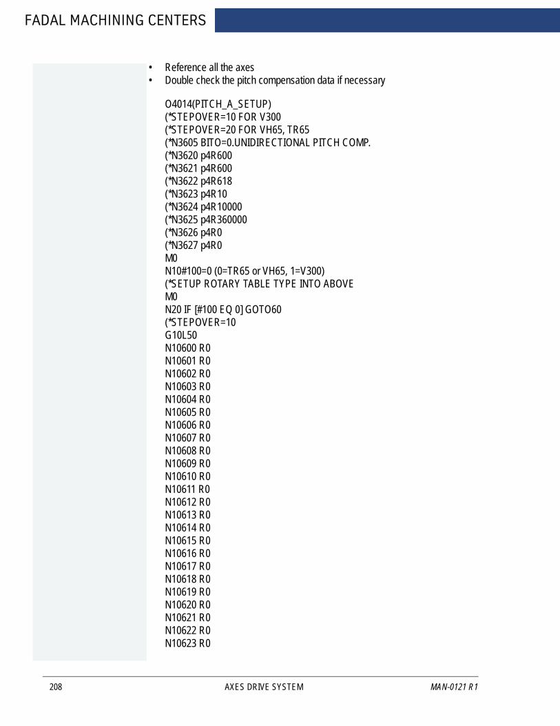
FADAL MACHINING CENTERS
208
• Reference all the axes• Double check the pitch compensation data if necessary
O4014(PITCH_A_SETUP)(*STEPOVER=10 FOR V300(*STEPOVER=20 FOR VH65, TR65(*N3605 BITO=0.UNIDIRECTIONAL PITCH COMP.(*N3620 p4R600(*N3621 p4R600(*N3622 p4R618(*N3623 p4R10(*N3624 p4R10000(*N3625 p4R360000(*N3626 p4R0(*N3627 p4R0M0N10#100=0 (0=TR65 or VH65, 1=V300)(*SETUP ROTARY TABLE TYPE INTO ABOVEM0N20 IF [#100 EQ 0] GOTO60(*STEPOVER=10G10L50N10600 R0N10601 R0N10602 R0N10603 R0N10604 R0N10605 R0N10606 R0N10607 R0N10608 R0N10609 R0N10610 R0N10611 R0N10612 R0N10613 R0N10614 R0N10615 R0N10616 R0N10617 R0N10618 R0N10619 R0N10620 R0N10621 R0N10622 R0N10623 R0
AXES DRIVE SYSTEM MAN-0121 R1
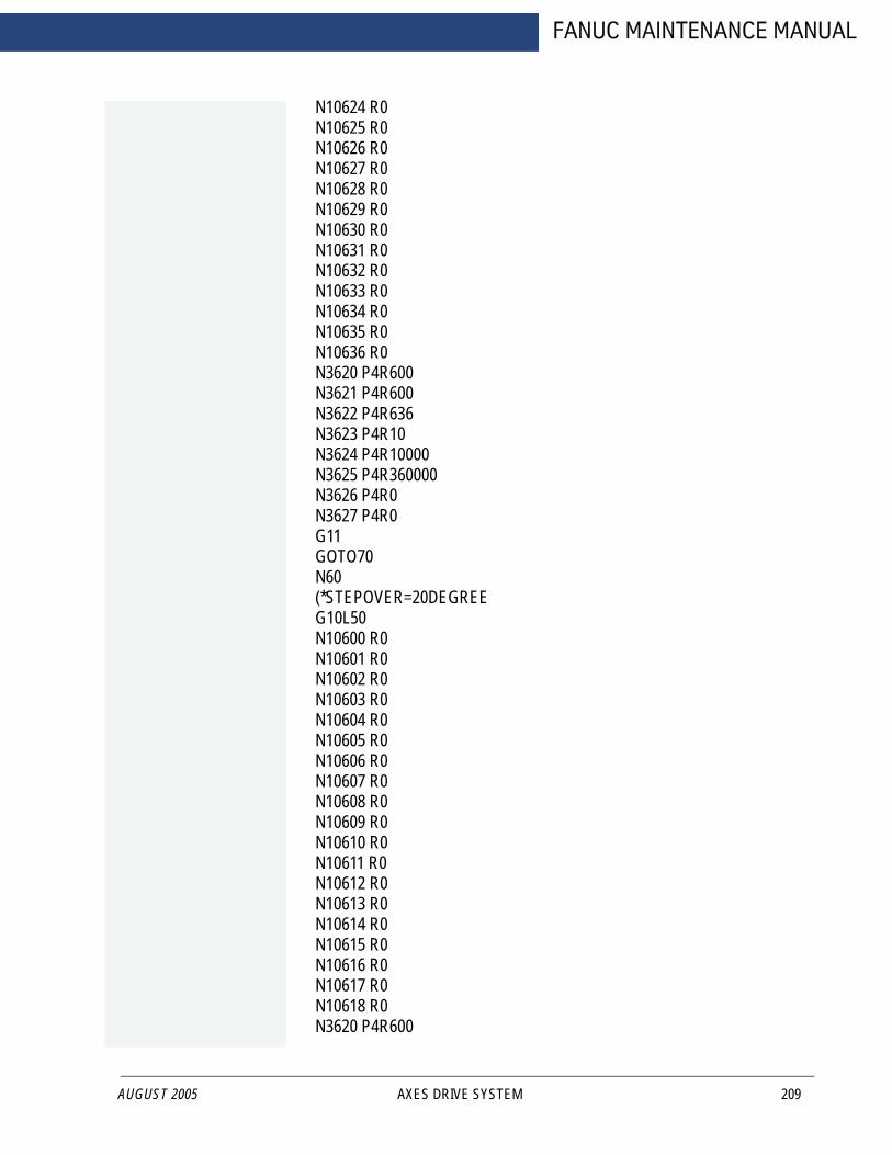
AUGUST 2005
FANUC MAINTENANCE MANUAL
N10624 R0N10625 R0N10626 R0N10627 R0N10628 R0N10629 R0N10630 R0N10631 R0N10632 R0N10633 R0N10634 R0N10635 R0N10636 R0N3620 P4R600N3621 P4R600N3622 P4R636N3623 P4R10N3624 P4R10000N3625 P4R360000N3626 P4R0N3627 P4R0G11GOTO70N60(*STEPOVER=20DEGREEG10L50N10600 R0N10601 R0N10602 R0N10603 R0N10604 R0N10605 R0N10606 R0N10607 R0N10608 R0N10609 R0N10610 R0N10611 R0N10612 R0N10613 R0N10614 R0N10615 R0N10616 R0N10617 R0N10618 R0N3620 P4R600
AXES DRIVE SYSTEM 209
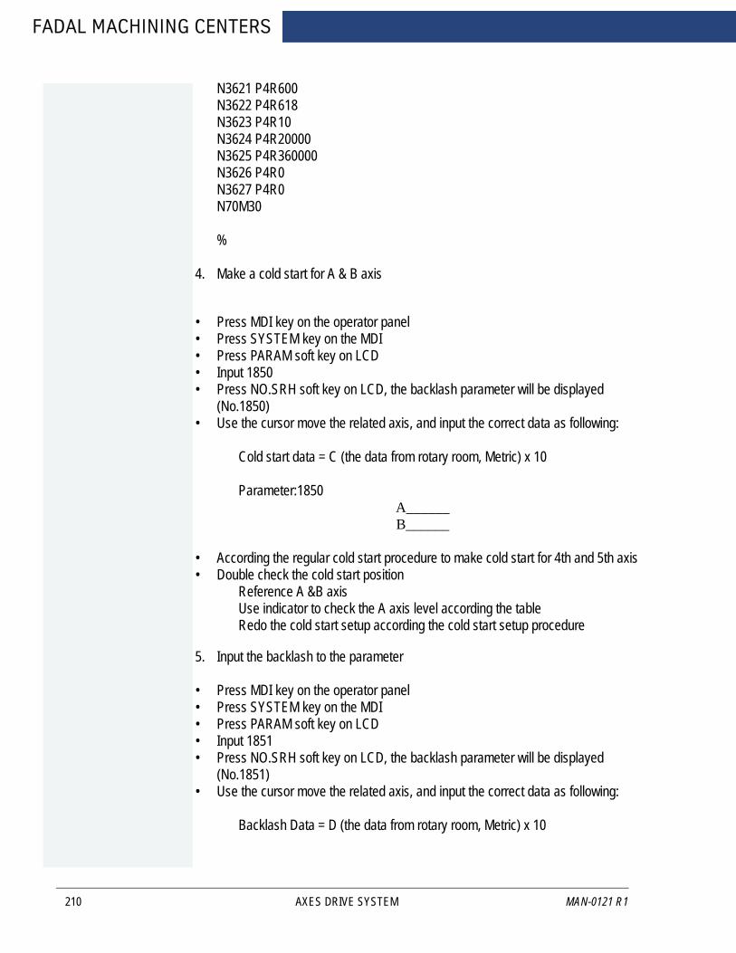
FADAL MACHINING CENTERS
210
N3621 P4R600N3622 P4R618N3623 P4R10N3624 P4R20000N3625 P4R360000N3626 P4R0N3627 P4R0N70M30
%
4. Make a cold start for A & B axis
• Press MDI key on the operator panel• Press SYSTEM key on the MDI• Press PARAM soft key on LCD • Input 1850• Press NO.SRH soft key on LCD, the backlash parameter will be displayed
(No.1850)• Use the cursor move the related axis, and input the correct data as following:
Cold start data = C (the data from rotary room, Metric) x 10
Parameter:1850A______B______
• According the regular cold start procedure to make cold start for 4th and 5th axis• Double check the cold start position
Reference A &B axisUse indicator to check the A axis level according the tableRedo the cold start setup according the cold start setup procedure
5. Input the backlash to the parameter
• Press MDI key on the operator panel• Press SYSTEM key on the MDI• Press PARAM soft key on LCD• Input 1851• Press NO.SRH soft key on LCD, the backlash parameter will be displayed
(No.1851)• Use the cursor move the related axis, and input the correct data as following:
Backlash Data = D (the data from rotary room, Metric) x 10
AXES DRIVE SYSTEM MAN-0121 R1
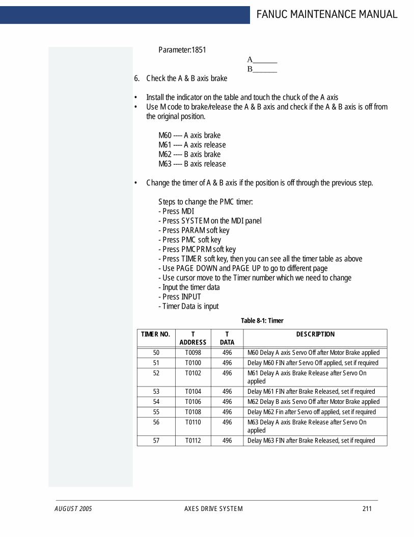
AUGUST 2005
FANUC MAINTENANCE MANUAL
Parameter:1851A______B______
6. Check the A & B axis brake
• Install the indicator on the table and touch the chuck of the A axis• Use M code to brake/release the A & B axis and check if the A & B axis is off from
the original position.
M60 ---- A axis brakeM61 ---- A axis releaseM62 ---- B axis brakeM63 ---- B axis release
• Change the timer of A & B axis if the position is off through the previous step.
Steps to change the PMC timer:- Press MDI- Press SYSTEM on the MDI panel- Press PARAM soft key- Press PMC soft key- Press PMCPRM soft key- Press TIMER soft key, then you can see all the timer table as above- Use PAGE DOWN and PAGE UP to go to different page- Use cursor move to the Timer number which we need to change- Input the timer data- Press INPUT- Timer Data is input
Table 8-1: Timer
TIMER NO. T ADDRESS
T DATA
DESCRIPTION
50 T0098 496 M60 Delay A axis Servo Off after Motor Brake applied51 T0100 496 Delay M60 FIN after Servo Off applied, set if required52 T0102 496 M61 Delay A axis Brake Release after Servo On
applied53 T0104 496 Delay M61 FIN after Brake Released, set if required54 T0106 496 M62 Delay B axis Servo Off after Motor Brake applied55 T0108 496 Delay M62 Fin after Servo off applied, set if required56 T0110 496 M63 Delay A axis Brake Release after Servo On
applied57 T0112 496 Delay M63 FIN after Brake Released, set if required
AXES DRIVE SYSTEM 211
FADAL MACHINING CENTERS
8.4 DIGITAL AXIS DRIVE SYSTEM
8.4.1 SETUP BACKLASH PROCEDURE
212
***Prepare: In MDI mode, input G21 to change machine to Metric display.
Follow the next procedure:
1. Reference all the axes.
Push Reference mode key and select reference mode, them push X/Y/Z key to move X/Y/Z axis to zero position. CNC screen will display XoYoZo.
2. Find out machine backlash manually. Record the backlash as data “A”
3. Input the backlash to the parameter
• Press [MDI] key on the operator panel• Press [SYSTEM] key on the MDI• Press [PARAM] soft key on LCD• Input 1851• Press [NO.SRH] soft key on LCD, the backlash parameter will be displayed
(No.1851)• Use the cursor to move the related axis, and input the correct data as following
Backlash Data B = A(Metric) x 10000
Parameter:1851X_____Y_____Z_____A_____B_____
4. Reference all the axes
Push Reference mode key and select reference mode, them push X/Y/Z key to move X/Y/Z axis to zero position. CNC screen will display X0Y0Z0.
5. Repeat steps 2 and 3 for all the axes
6. Baklash setup is finished.
8.4.2 WORK COORDINATE SETUP
FANUC Software option related with work coordinator procedure:
AXES DRIVE SYSTEM MAN-0121 R1
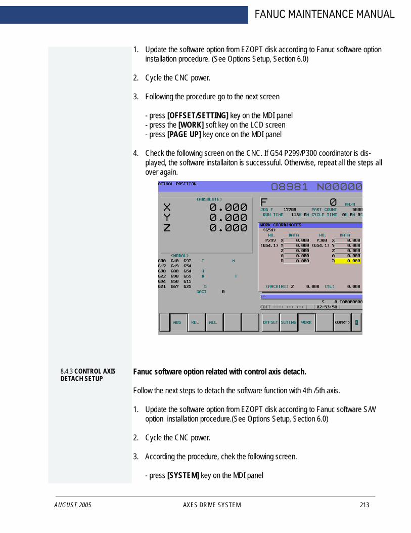
AUGUST 2005
FANUC MAINTENANCE MANUAL
1. Update the software option from EZOPT disk according to Fanuc software option installation procedure. (See Options Setup, Section 6.0)
2. Cycle the CNC power.
3. Following the procedure go to the next screen
- press [OFFSET/SETTING] key on the MDI panel- press the [WORK] soft key on the LCD screen- press [PAGE UP] key once on the MDI panel
4. Check the following screen on the CNC. If G54 P299/P300 coordinator is dis-played, the software installaiton is successuful. Otherwise, repeat all the steps all over again.
8.4.3 CONTROL AXIS DETACH SETUP
Fanuc software option related with control axis detach.
Follow the next steps to detach the software function with 4th /5th axis.
1. Update the software option from EZOPT disk according to Fanuc software S/W option installation procedure.(See Options Setup, Section 6.0)
2. Cycle the CNC power.
3. According the procedure, chek the following screen.
- press [SYSTEM] key on the MDI panel
AXES DRIVE SYSTEM 213
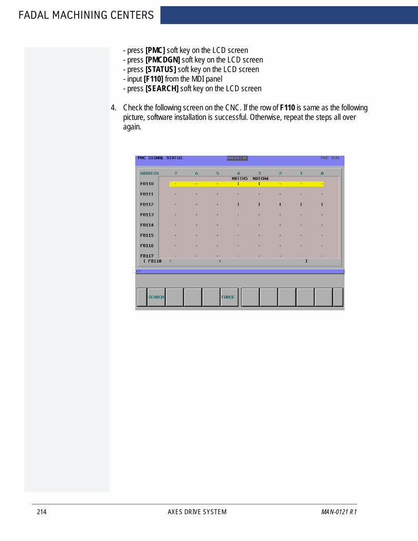
FADAL MACHINING CENTERS
214
- press [PMC] soft key on the LCD screen- press [PMCDGN] soft key on the LCD screen- press [STATUS] soft key on the LCD screen- input [F110] from the MDI panel- press [SEARCH] soft key on the LCD screen
4. Check the following screen on the CNC. If the row of F110 is same as the following picture, software installation is successful. Otherwise, repeat the steps all over again.
AXES DRIVE SYSTEM MAN-0121 R1

FANUC MAINTENANCE MANUAL
AUGUST 2005
9.0 PALLET CHANGER
PALLET CHANGER 215

FADAL MACHINING CENTERS
9.1 INSTALLATION OF PALLET CHANGER
216
1. The left, front, lower edge of the base must be a minimum of 2” from the floor. Levelthe machine on the 1.5” leveling pads that were shipped with the machine (see theFadal Maintenance Manual Pre-Installation/Installation Section for documentationon leveling the VMC).
2. Verify that the X and Y axis cold start positions are correct. The X axis must travelto X-20” and the Y axis must travel to Y-10”and Y+10”. Cold start the machine.
3. Enter the Parameters page and select the Pallet Changer.
a. At the ENTER NEXT COMMAND screen, type SETP and press the ENTERbutton.
b. Press the SPACE BAR to select the second page.c. Press the D button, to page down to the PALLET category. Select the number
2, which answers yes to the question “Do you have a Pallet Changer”. Pressthe ENTER button and then press the MANUAL button to exit the Parameterspage.
4. Verify that the rail support bolts on the Pallet Receiver are installed and are all theway up.
Figure 9-1 Verify Rail Support Bolts are Installed and All the Way Up
5. Verify that the rails and the bolts are high enough to clear the VMC sheetmetal. Ifnot, adjust the Pallet Receiver legs clockwise to raise the level of the support rails.
6. Move the VMC table to X=-20” and Y=10”.
7. Open the Pallet Changer door using the UTILITIES command.
a. In the ENTER NEXT COMMAND mode, type UT and press the ENTER button.b. Select option #5 PALLET CHANGER.c. Select option #4 SERVICE UTILITY.d. Select option #2 OPEN/CLOSE DOOR.
PALLET CHANGER MAN-0121 R1
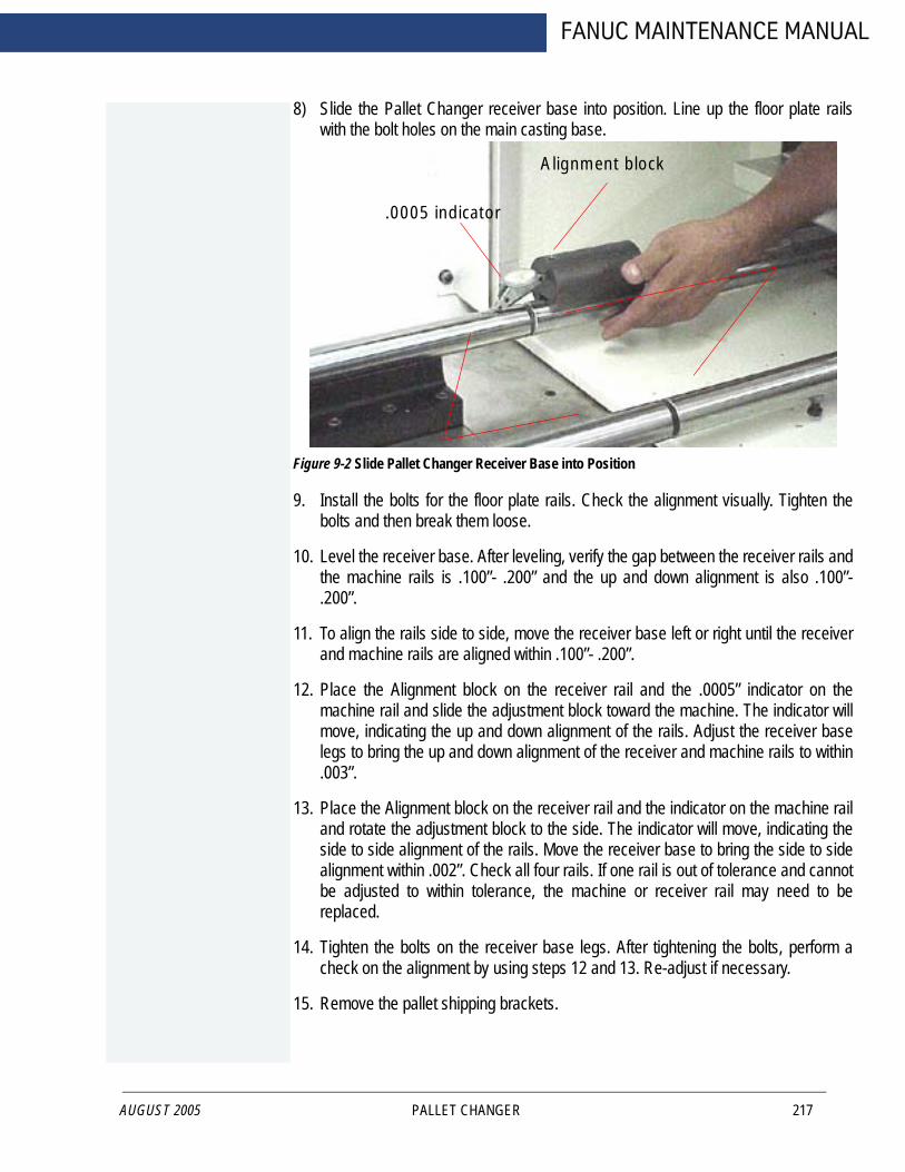
AUGUST 2005
FANUC MAINTENANCE MANUAL
8) Slide the Pallet Changer receiver base into position. Line up the floor plate railswith the bolt holes on the main casting base.
Figure 9-2 Slide Pallet Changer Receiver Base into Position
9. Install the bolts for the floor plate rails. Check the alignment visually. Tighten thebolts and then break them loose.
10. Level the receiver base. After leveling, verify the gap between the receiver rails andthe machine rails is .100”- .200” and the up and down alignment is also .100”-.200”.
11. To align the rails side to side, move the receiver base left or right until the receiverand machine rails are aligned within .100”- .200”.
12. Place the Alignment block on the receiver rail and the .0005” indicator on themachine rail and slide the adjustment block toward the machine. The indicator willmove, indicating the up and down alignment of the rails. Adjust the receiver baselegs to bring the up and down alignment of the receiver and machine rails to within.003”.
13. Place the Alignment block on the receiver rail and the indicator on the machine railand rotate the adjustment block to the side. The indicator will move, indicating theside to side alignment of the rails. Move the receiver base to bring the side to sidealignment within .002”. Check all four rails. If one rail is out of tolerance and cannotbe adjusted to within tolerance, the machine or receiver rail may need to bereplaced.
14. Tighten the bolts on the receiver base legs. After tightening the bolts, perform acheck on the alignment by using steps 12 and 13. Re-adjust if necessary.
15. Remove the pallet shipping brackets.
Machine Rails
ReceiverRails
Alignment block
.0005 indicator
PALLET CHANGER 217
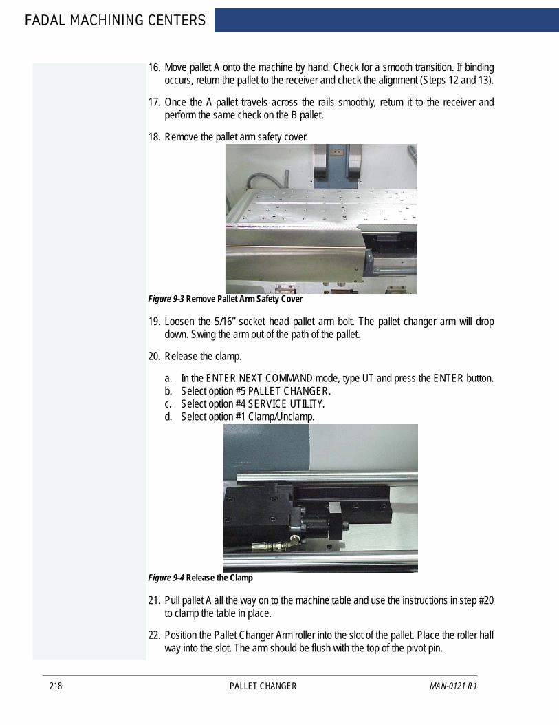
FADAL MACHINING CENTERS
218
16. Move pallet A onto the machine by hand. Check for a smooth transition. If bindingoccurs, return the pallet to the receiver and check the alignment (Steps 12 and 13).
17. Once the A pallet travels across the rails smoothly, return it to the receiver andperform the same check on the B pallet.
18. Remove the pallet arm safety cover.
Figure 9-3 Remove Pallet Arm Safety Cover
19. Loosen the 5/16” socket head pallet arm bolt. The pallet changer arm will dropdown. Swing the arm out of the path of the pallet.
20. Release the clamp.
a. In the ENTER NEXT COMMAND mode, type UT and press the ENTER button.b. Select option #5 PALLET CHANGER.c. Select option #4 SERVICE UTILITY.d. Select option #1 Clamp/Unclamp.
Figure 9-4 Release the Clamp
21. Pull pallet A all the way on to the machine table and use the instructions in step #20to clamp the table in place.
22. Position the Pallet Changer Arm roller into the slot of the pallet. Place the roller halfway into the slot. The arm should be flush with the top of the pivot pin.
Pallet arm safety cover
PALLET CHANGER MAN-0121 R1

AUGUST 2005
FANUC MAINTENANCE MANUAL
23. Tighten the 5/16” socket head pallet arm bolt to 35-40 foot pounds.
24. Store pallet A.
a. In the ENTER NEXT COMMAND mode, type UT and press the ENTER button.b. Select option #5 PALLET CHANGERc. Select option #4 SERVICE UTILITYd. Select option #3 Store Pallet
25. If the pallet moves smoothly, tighten the rail slide bolts that are connected to thebase.
26. Check pallet A and verify that the pallet is resting properly on the receiver roller. Ifthe pallet is not resting properly on the roller, then adjust the pallet stop blockposition on the pallet.
a. Remove the cover over the roller.•Remove the two 5/16” hex head bolts that are holding the cover in place.•Remove the cover.
b. Loosen the two 9/16” hex head bolts that are located underneath the palletstop block.
c. Slide the stop block until it rests properly over the roller.
Figure 9-5 Remove Cover; Loosen Bolts; Slide Stop Block Over Roller
27. Jog the table back to pallet B and load pallet B.
a. In the ENTER NEXT COMMAND mode, type UT and press the ENTER button.b. Select option #5 PALLET CHANGER; press the ENTER button.c. Select option #4 SERVICE UTILITY; press the ENTER button.d. Select option #8 JOG.e. Press the JOG key on the keypad and jog the Y-axis to Y= -10.
Lock block cover Lock block Receiver lock roller
The bolts for the lock blockare located underneath.
PALLET CHANGER 219

FADAL MACHINING CENTERS
220
f. Verify that the arm is lined up with the groove in pallet B. If the arm is not linedup with the groove, move the pallet forward or backward to allow the arm toenter the groove.
g. Press the manual button to return to the utility menu. Press Option #4 LOADPALLET.
28. If pallet B loaded smoothly, store pallet B and verify that the pallet stop block isresting properly on the roller. If the pallet is not resting properly on the receiverroller, adjust the positioning (refer to step #26).
29. Drill holes in the concrete through the holes in the receiver base legs. Install themounting bolts and tighten.
30. Verify the alignment, by performing several pallet changes using the utilities menu.
31. Adjust the pallet rail support bolts down until they touch the sheetmetal. Tighten thelock nut.
PALLET CHANGER MAN-0121 R1
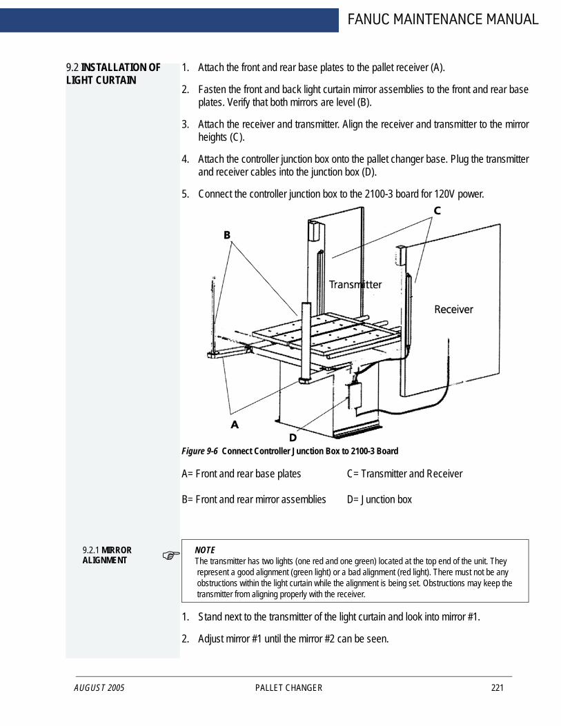
FANUC MAINTENANCE MANUAL
9.2 INSTALLATION OF LIGHT CURTAIN
AUGUST 2005
1. Attach the front and rear base plates to the pallet receiver (A).
2. Fasten the front and back light curtain mirror assemblies to the front and rear baseplates. Verify that both mirrors are level (B).
3. Attach the receiver and transmitter. Align the receiver and transmitter to the mirrorheights (C).
4. Attach the controller junction box onto the pallet changer base. Plug the transmitterand receiver cables into the junction box (D).
5. Connect the controller junction box to the 2100-3 board for 120V power.
Figure 9-6 Connect Controller Junction Box to 2100-3 Board
A= Front and rear base plates C= Transmitter and Receiver
B= Front and rear mirror assemblies D= Junction box
9.2.1 MIRROR ALIGNMENT
NOTE The transmitter has two lights (one red and one green) located at the top end of the unit. They represent a good alignment (green light) or a bad alignment (red light). There must not be any obstructions within the light curtain while the alignment is being set. Obstructions may keep the transmitter from aligning properly with the receiver.
1. Stand next to the transmitter of the light curtain and look into mirror #1.
2. Adjust mirror #1 until the mirror #2 can be seen.
PALLET CHANGER 221
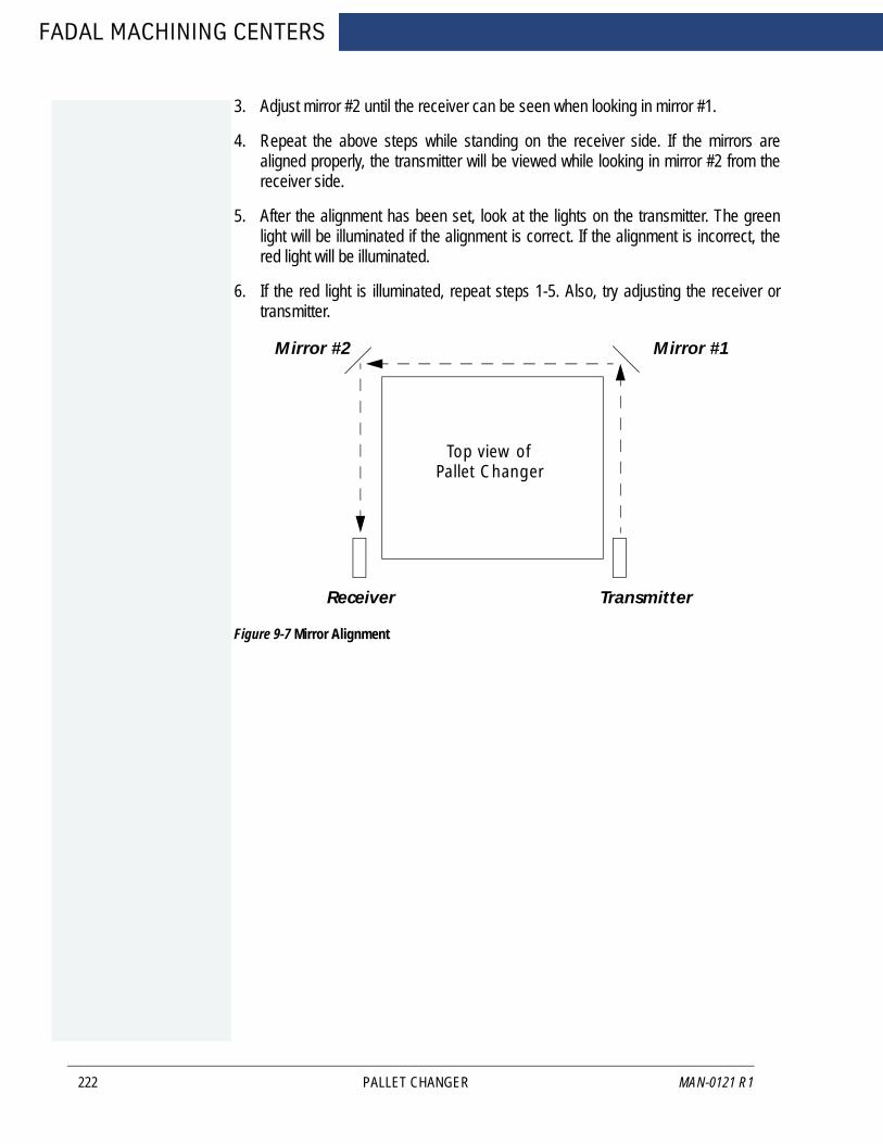
FADAL MACHINING CENTERS
222
3. Adjust mirror #2 until the receiver can be seen when looking in mirror #1.
4. Repeat the above steps while standing on the receiver side. If the mirrors arealigned properly, the transmitter will be viewed while looking in mirror #2 from thereceiver side.
5. After the alignment has been set, look at the lights on the transmitter. The greenlight will be illuminated if the alignment is correct. If the alignment is incorrect, thered light will be illuminated.
6. If the red light is illuminated, repeat steps 1-5. Also, try adjusting the receiver ortransmitter.
Figure 9-7 Mirror Alignment
TransmitterReceiver
Mirror #1Mirror #2
Top view of Pallet Changer
PALLET CHANGER MAN-0121 R1

FANUC MAINTENANCE MANUAL
9.3 SETTING THE SENSOR ON THE 1840 BOARD
9.3.1 PURPOSE
AUGUST 2005
During a pallet change, the table will move to the table limits. If there is anything blocking the progress of the Y-axis, the current of the motor will be too high. The 1840 board senses when the Y-axis motor is receiving too much current and will inhibit the pallet operation.
WARNING!This procedure is for DC machines only. AC machines monitor motor overload through the axis controller card.
1. Install the 1840 board into the VMC.
2. Power on the VMC.
3. Enter the ENTER NEXT COMMAND mode and enter a program for testing thesensor.
a. Type PR and press the ENTER button.b. Select option #3 START A NEW PROGRAM.c. Type a program number that is not currently in the system and press the
ENTER button.d. Select option #6 EXIT.e. Type IN and press the ENTER button.f. Enter the following program:
N1 M49 F150. G1 G91
N2 Y5.
N3 Y-5.
N4 M99P1
4. Start the program. Press the AUTO button to start the program running.
5. On the 1840 board, turn the pot clockwise until the red LED is on continuously.
6. Turn the pot counterclockwise until the LED gives one solid blink once at the end ofeach move.
7. Stop the program.
a. Press the SLIDE HOLD button.b. Press the MANUAL button.
PALLET CHANGER 223

FADAL MACHINING CENTERS
224
8. Make a pallet change In the MANUAL DATA INPUT mode (do not make a palletchange from the UTILITIES menu; a pallet change from the UTILITIES menu doesnot utilize all of the functions of a complete pallet change).
In the MANUAL DATA INPUT mode:
a. Turn the Rapid travel 3-position switch to 100%.b. Type M31.c. Press the ENTER BUTTON.
9. If the INHIBIT message is displayed on the monitor, repeat steps #3-#8.
PALLET CHANGER MAN-0121 R1

FANUC MAINTENANCE MANUAL
9.4 OPERATION
AUGUST 2005
The pallet changer may be operated within the program or by use of the UT (Utilities) command.
9.4.1 PALLETS
There are 2 pallets on the pallet changer. They are identified as Pallet A and Pallet B. Pallet A is the closest pallet to the operator.There are 3 positions for the pallets: loaded, stored, and working.
• The loaded position is when the pallet is locked onto the table with the hydraulic clamp.
• The stored position is when the pallet is ready to be loaded onto the table.• The working position is when the pallet is released from the stored position. The
pallet must be moved to this position manually. Push the release lever down, to pull the table to the working position.
1. The pallets move on rails with circular bearings.
2. The pallet is locked in place on the table with a hydraulic clamp.
3. The clamp is released with program coding of a pallet change or through the utilitymenu.
9.4.2 M-FUNCTIONS
There are 3 M-Functions that may be used to operate the pallet changer:• M31 Exchange Pallets - This function performs a pallet exchange. The pallet changer will store the current pallet and load the other pallet.
• M32 Store and Load Pallet A - This function is used when only pallet A is to be uti-lized. This exchange is performed the same as the M31 function. When pallet A is on the table, it is placed in the stored position. The machine will enter the waiting state, while the operator changes parts. When the START button is pressed, pallet A is loaded.
PALLET CHANGER 225

FADAL MACHINING CENTERS
9.5 MAINTENANCE SCHEDULE
9.5.1 EACH PART CYCLE
226
1. Use an M20 in the program to make it automatic. Frequent washing out of chipsprevents them from building up into difficult-to-remove piles.
2. Blow away any chips that may lodge underneath Pallet in Hydraulic Arm groove.
9.5.2 DAILY MAINTE-NANCE
1. Put both Pallets away onto stand. Put tool in spindle. Wash down interior withcoolant hose nozzle, using care to keep splash away from Automatic Tool Changer,Head assembly, or any wiring connections.
2. Clean chips from trough behind Table and Saddle, and on Sliding.
3. Guard, and inspect between front Y-axis way cover and front of machine for chipbuildup.
4. Remove screen/tank cover over fluid tank, and clean screen protecting pumps.
5. Using tool, check for any chip buildup in tank ahead of screen.
6. Check tank reservoir fluid level, and refill as necessary.
7. Check Waylube level, refill with Castrol Magna BD68, Shell Tonna V68, or MobilVactra #2.
8. Check for air pressure. Single regulators should be set for 80PSI. Dual regulatorsshould be set at 80PSI on the left gauge, and 90-100PSI maximum on the rightgauge.
9. Move X-axis to either side, and flip over outer X-axis way cover. Inspect for chipbuildup, and clean. Check for waylube presence on both X-axis ways. Inspect Z-axis and Y-axis as well.
10. Check pressures/vacuum on Coolant-Thru pump filter and replace filter, ifnecessary.
9.5.3 WEEKLY MAINTENANCE
1. Check Hydraulic Fluid level for Pallet Clamp on top of machine. Use Mobil DTEHeavy Medium.
2. Remove Hydraulic Arm pump cover, and inspect Hydraulic Arm system, refillingfluid if necessary.
3. Check Hydraulic Arm chain tension by push/pull on arm.
4. Remove Head Cover, and inspect fluid lines for Hi/Lo Idler assembly, refilling, ifnecessary.
PALLET CHANGER MAN-0121 R1

AUGUST 2005
FANUC MAINTENANCE MANUAL
5. Remove all tools from tool changer, and clean out any chip buildup found. Whenreturning tools to ATC, inspect retention ring tension on tool holders for excessivelooseness, replacing rings, if necessary.
6. Disconnect front Y-axis way cover from saddle, and check for chip buildup.
7. Inspect under Y-axis motor for chips, and clear out drain ports under Y-axis waysnearest the column.
9.5.4 MONTHLY MAINTENANCE
1. Carefully remove pallets, and grease rail bearings, using care not to damage lipseals.
2. Remove spindle motor top filter cover, and inspect filter. Replace, if necessary.
3. Inspect Pallet Roller latch system for both Pallets on stand.
4. Check Pallet Lift Door for smooth operation.
5. Inspect Chiller cabinet for low fluid in container, should be 1/2 to 3/4 full.
6. Inspect Chiller recirculation pump filter, and clean as needed.
7. Blow air into top of Chiller louvers to clear out dirt collecting on condenser.
8. At bottom of rear cabinet, remove fan filter screen and clean.
9. Inspect front door rollers, tightening as necessary.
10. Check door interlock system for proper operation.
11. Remove head cover and inspect belts, and check for any Coolant-thru systemleaks.
12. Inspect all cables, hoses, and tubing for looseness, or damage.
PALLET CHANGER 227

FADAL MACHINING CENTERS
9.6 MIDACO PALLET CHANGER
228
9.6.1 REQUIREMENTS
Power requirementsThe pallet changer requires a 230V/Single Phase/30AMP power feed. The power is to be connected to the top of the power disconnect located in the pallet changer’s electrical enclosure. The control panel is located inside the pallet shuttle. Release the two latches on the side of the shuttle to access the electrical enclosure. The power disconnect is in the upper right hand corner of the black electrical enclosure. Your power source must satisfy all local and national electrical codes. The power cable must NOT lie on the floor, but be wire-tied to the underside of the pallet shuttle. Install the power cable in a location that does not interfere with the operator and is NOT exposed to any traffic in your shop.
CNC Interface (M-Codes)
Two dedicated “M” functions with dry contacts that are M-Fin cancelable are required.
Air Supply requirements
The pallet changer requires a dry air supply of 12.5CFM at 100 P.S.I. during a pallet change. The minimum air requirement for your pallet load will vary with weight. The pallet may not unclamp if the proper air supply is not available. The air pressure may be increased to a maximum of 120 PSI. This requires a 3/8” I.D or larger compressed air supply line with 1/4” NPT fitting.
9.6.2 MAINTENANCE
The following is a list of required maintenance for the pallet changer. These procedures must be followed in order to keep your machine in good working condition.Daily
1. Clean all of the chips off the receiver, and the machine tool’s table. Check under the draw plate and remove any chip build-up there. Also, check for and remove any chips on the underside of the pallets and pallet rails.
2. Clean the chips off of the shuttle bed and rails.
Weekly
1. Check the air supply to make sure air is dry, and free of contaminates.
2. Clean exterior surfaces using a mild cleaner; do not use solvents.
PALLET CHANGER MAN-0121 R1

AUGUST 2005
FANUC MAINTENANCE MANUAL
Monthly
1. Check the air pressure level. Maintain a constant supply of 90-120 PSI.
2. Check the cam followers to make sure they move freely.
For more detailed information see Midaco Pallet Changer Servo Drive Manual.
PALLET CHANGER 229

FADAL MACHINING CENTERS
2.6.3 PALLET
230
PALLET CHANGER MAN-0121 R1
FANUC MAINTENANCE MANUAL
AUGUST 2005
10.0 SPINDLE DRIVE SYSTEMS
SPINDLE DRIVE SYSTEMS 231

FADAL MACHINING CENTERS
10.1 BELT DRIVE SYSTEMS
10.1.1 POSI-DRIVE BELT SYSTEM
232
The Posi-Drive Belt System features two belts that run on a 1-2 and 2-1 reduction pulley arrangement.
Spindle Belts Replacement on Auto Hi/low System
The spindle drive belts are Gates 315K10. Gates manufactures the belts to Fadal specification. When replacing the spindle belts, use only the belts supplied by Fadal Machining Centers. The belts supplied by Fadal are sized.
The following steps are for replacing the belts on the auto HI/LOW spindle:
1. Verify that the VMC is aligned with the cold start indicators.
2. Power off the VMC and lock out the main disconnect.
3. Disconnect the air supply from the VMC.
4. Remove four each of the 1/4” cap bolts on the Head Cover and remove the HeadCover. Cut all the wire ties holding the air lines and wires in place.
5. The Auto Hi/Low pistons need to be released. Determine which piston is applyingforce on the belts, the upper piston is the low speed belt piston the lower piston isthe high speed belt piston. To release the actuator, push the check valve into theactuator. With the check valve released, pull the idler away from the belts.
Figure 10-1: Release Check Valve and Pull Idler Away from the Belts
SPINDLE DRIVE SYSTEMS MAN-0121 R1
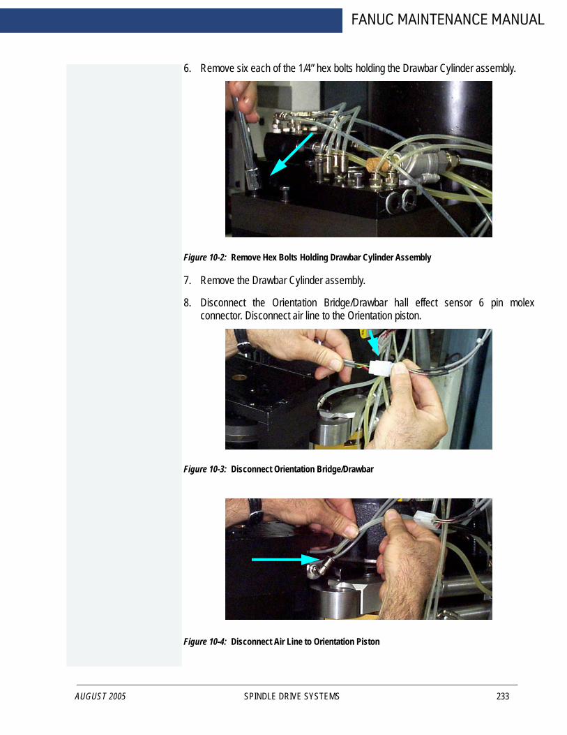
AUGUST 2005
FANUC MAINTENANCE MANUAL
6. Remove six each of the 1/4” hex bolts holding the Drawbar Cylinder assembly.
Figure 10-2: Remove Hex Bolts Holding Drawbar Cylinder Assembly
7. Remove the Drawbar Cylinder assembly.
8. Disconnect the Orientation Bridge/Drawbar hall effect sensor 6 pin molexconnector. Disconnect air line to the Orientation piston.
Figure 10-3: Disconnect Orientation Bridge/Drawbar
Figure 10-4: Disconnect Air Line to Orientation Piston
SPINDLE DRIVE SYSTEMS 233
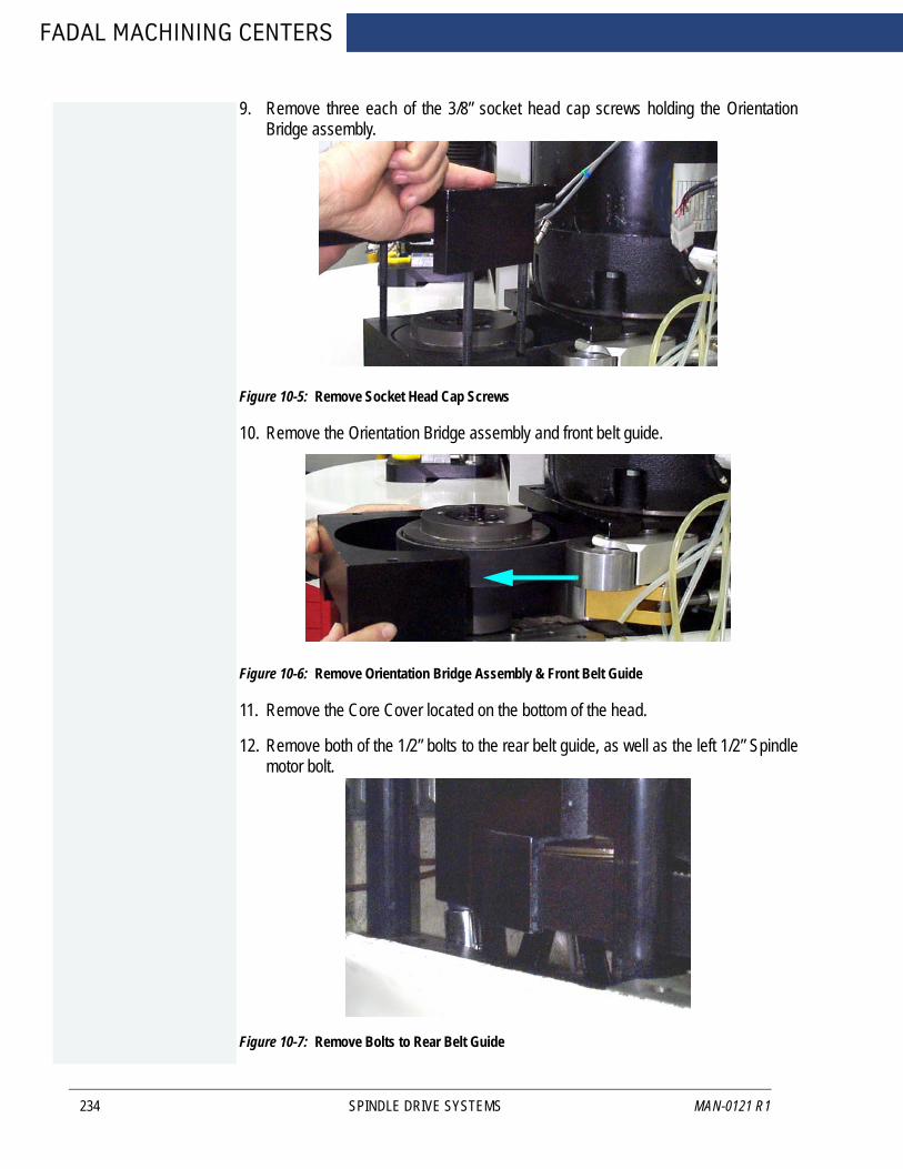
FADAL MACHINING CENTERS
234
9. Remove three each of the 3/8” socket head cap screws holding the OrientationBridge assembly.
Figure 10-5: Remove Socket Head Cap Screws
10. Remove the Orientation Bridge assembly and front belt guide.
Figure 10-6: Remove Orientation Bridge Assembly & Front Belt Guide
11. Remove the Core Cover located on the bottom of the head.
12. Remove both of the 1/2” bolts to the rear belt guide, as well as the left 1/2” Spindlemotor bolt.
Figure 10-7: Remove Bolts to Rear Belt Guide
SPINDLE DRIVE SYSTEMS MAN-0121 R1
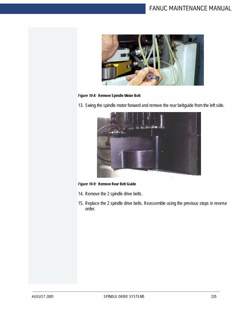
AUGUST 2005
FANUC MAINTENANCE MANUAL
Figure 10-8: Remove Spindle Motor Bolt
13. Swing the spindle motor forward and remove the rear belt guide from the left side.
Figure 10-9: Remove Rear Belt Guide
14. Remove the 2 spindle drive belts.
15. Replace the 2 spindle drive belts. Reassemble using the previous steps in reverseorder.
SPINDLE DRIVE SYSTEMS 235

FADAL MACHINING CENTERS
10.1.2 MOTOR PLATE TENSIONER CABLE
236
Machines equipped with a motor plate tensioner cable system (10K), as shown in the figure below, will need adjusting when belts are replaced.
Adjustment procedure:
1. Disconnect the air supply from the machine. Remove the tension from the belts.Use either a dial indicator or a travel indicator.
Figure 10-10: Place Indicator
2. Once the indicator is in place, you will need two 9/16” open end wrenches to tightenand lock the cable tensioner screw.
3. Zero the indicator and slowly turn the 3/8” hex head bolt.
4. Adjust the screw until the plate moves.002 to .005 on the indicator.
5. After adjusting, lock down the 3/8” jam nut with the other wrench while holding theadjuster screw. Watch the indicator to verify that there is no movement.
Hex head bolt
SPINDLE DRIVE SYSTEMS MAN-0121 R1
FANUC MAINTENANCE MANUAL
10.2 HYDRAULIC HI/LOW SYSTEM
AUGUST 2005
The hydraulic hi/low system requires very little maintenance. It is an air over oil system with check valves. Periodically check that you can see fluid in the 1/4 inch lines that go to the rear of the cylinder. If the lines have an excessive amount of bubbles then it is an indication that the oil level is low.
Filling
1. Remove the head cover.
2. Disconnect the air supply from the machine.
3. With the air source disconnected one actuator will still be engaged. To release theactuator, push the check valve into the actuator.
4. With the check valve released, pull the idler away from the belts.
5. Remove the 1/4“line that goes to the rear of the cylinder and fill with Mobil DTEheavy medium oil.
6. The reservoir is full when oil enters the 5/32 line on the actuator.
WARNING!DO NOT allow an excessive amount of oil to flow into the separator.
7. Reattach the 1/4“line to the fitting on the cylinder.
8. Repeat the above steps for the other range.
9. Reconnect the air supply to the machine.
WARNING!Verify that the oil lines are secure.
10. In MDI, cycle between the high and low ranges about 10 times. This will fill thecylinders.
MDI Example
Type:
MD,ENTER
S.1, ENTER
S.2, ENTER
Repeat the S.1 and S.2 to continue switching ranges.
SPINDLE DRIVE SYSTEMS 237
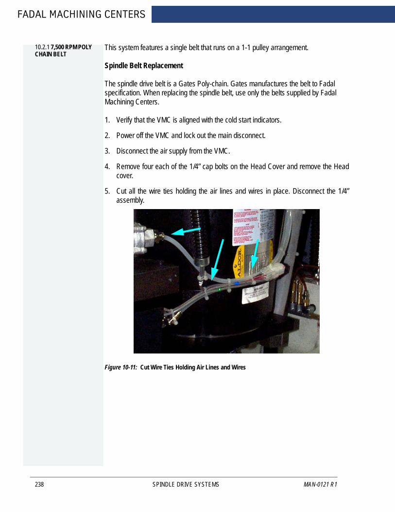
FADAL MACHINING CENTERS
10.2.1 7,500 RPM POLY CHAIN BELT
238
This system features a single belt that runs on a 1-1 pulley arrangement.
Spindle Belt Replacement
The spindle drive belt is a Gates Poly-chain. Gates manufactures the belt to Fadal specification. When replacing the spindle belt, use only the belts supplied by Fadal Machining Centers.
1. Verify that the VMC is aligned with the cold start indicators.
2. Power off the VMC and lock out the main disconnect.
3. Disconnect the air supply from the VMC.
4. Remove four each of the 1/4” cap bolts on the Head Cover and remove the Headcover.
5. Cut all the wire ties holding the air lines and wires in place. Disconnect the 1/4”assembly.
Figure 10-11: Cut Wire Ties Holding Air Lines and Wires
SPINDLE DRIVE SYSTEMS MAN-0121 R1
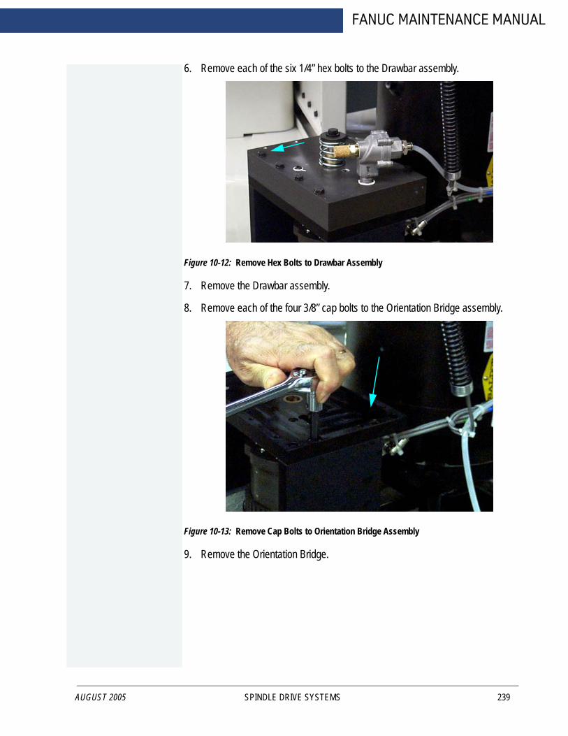
AUGUST 2005
FANUC MAINTENANCE MANUAL
6. Remove each of the six 1/4” hex bolts to the Drawbar assembly.
Figure 10-12: Remove Hex Bolts to Drawbar Assembly
7. Remove the Drawbar assembly.
8. Remove each of the four 3/8” cap bolts to the Orientation Bridge assembly.
Figure 10-13: Remove Cap Bolts to Orientation Bridge Assembly
9. Remove the Orientation Bridge.
SPINDLE DRIVE SYSTEMS 239

FADAL MACHINING CENTERS
240
10. Loosen each of the two 1/2” hex bolts to the Spindle motor.
Figure 10-14: Loosen Hex Bolts to Spindle Motor
11. Swing the Spindle motor forward.
12. Remove the Spindle drive belt.
13. Install the new Spindle drive belt.
14. Mount a Mag base with an indicator on the head and touch off the top-front edge ofthe spindle pulley.
15. Set a zero reading while there is NO belt tension, then push back on the Spindlemotor until about .0005" of deflection is seen on the indicator.
16. Tighten two each of the 1/2” hex bolts to the Spindle motor.
17. Verify that the reading has not changed.
NOTE If the belt tension is too tight, then vibration will appear at the tool tip, and a poor finish may result.
18. Reassemble using the previous steps in reverse order.
SPINDLE DRIVE SYSTEMS MAN-0121 R1
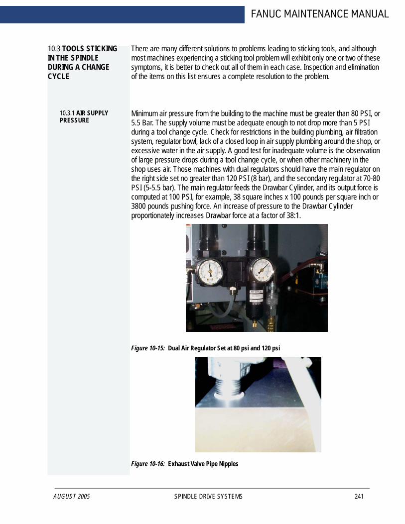
FANUC MAINTENANCE MANUAL
10.3 TOOLS STICKING IN THE SPINDLE DURING A CHANGE CYCLE
AUGUST 2005
There are many different solutions to problems leading to sticking tools, and although most machines experiencing a sticking tool problem will exhibit only one or two of these symptoms, it is better to check out all of them in each case. Inspection and elimination of the items on this list ensures a complete resolution to the problem.
10.3.1 AIR SUPPLY PRESSURE
Minimum air pressure from the building to the machine must be greater than 80 PSI, or 5.5 Bar. The supply volume must be adequate enough to not drop more than 5 PSI during a tool change cycle. Check for restrictions in the building plumbing, air filtration system, regulator bowl, lack of a closed loop in air supply plumbing around the shop, or excessive water in the air supply. A good test for inadequate volume is the observation of large pressure drops during a tool change cycle, or when other machinery in the shop uses air. Those machines with dual regulators should have the main regulator on the right side set no greater than 120 PSI (8 bar), and the secondary regulator at 70-80 PSI (5-5.5 bar). The main regulator feeds the Drawbar Cylinder, and its output force is computed at 100 PSI, for example, 38 square inches x 100 pounds per square inch or 3800 pounds pushing force. An increase of pressure to the Drawbar Cylinder proportionately increases Drawbar force at a factor of 38:1.
Figure 10-15: Dual Air Regulator Set at 80 psi and 120 psi
Figure 10-16: Exhaust Valve Pipe Nipples
SPINDLE DRIVE SYSTEMS 241

FADAL MACHINING CENTERS
10.3.2 DRAWBAR CYLINDER HALL EFFECTS SWITCH
242
Tool "Popping" can be reduced on machines equipped with Drawbar Cylinder Hall Effects switches, by checking the adjustment on the switch. If the switch is up too high, then the Z-axis may start up prematurely in the Tool Extraction cycle, wrenching the tool out of the spindle. Note that there is a new parameter in SETP labelled “Do you have Air Valve feedback?” This does not mean that electric signals are returning to the control from the air valve. It means that there could be Hall Effects switches on the Idlers and Drawbar Cylinder, and if so, the answer would be “YES”. To answer “NO” might mean that the control will ignore any such feedback and Z-axis may lift off the tool prematurely.
10.3.3 INSUFFICIENT AIR VOLUME: MAC IN-LINE VALVE
In some cases, the rear MAC In-Line valve that delivers air to the Drawbar Cylinder may have reduced output by volume. There have been cases of 40% reduction in airflow when this valve experiences a failure. This condition will not allow the Drawbar Cylinder to fill fast enough to provide enough impact to operate properly. A simple test is to swap the valve with another in the manifold and retest.
10.3.4 AIR LEAKS: EXHAUST VALVE
Inside the Exhaust Valve on top of the Drawbar Cylinder is a diaphragm valve/seat. A tiny pinhole leak in the diaphragm will cause the valve to leak out the exhaust and not fill up the Drawbar Cylinder. Inspect the diaphragm visually for a rupture, and replace if necessary. Part numbers are VLV-0032 and VLV-0033 for repair kits, the large valve style or the small valve style, respectively.
10.3.5 AIR LEAKS: EXHAUST VALVE NIP-PLE
The pipe nipple that attaches the Exhaust Valve to the Drawbar Cylinder Housing may be cracked from overtightening, and then leak. Inspect and replace, if necessary.
10.3.6 AIR LEAKS: DRAWBAR CYLINDER BUSHING
Test for an air leak with soapy water sprayed around the air lines. The bronze bushing that guides the Drawbar Cylinder Shaft may be worn, or damaged, or too rough internally to prevent premature wear to the O-ring around the shaft. Disassemble the Drawbar Cylinder and inspect/replace the O-ring and bushing. A new bushing design will be available soon to not only house a second O-ring, but provide a smoother surface to reduce O-ring wear. It will be retrofittable to all earlier Drawbar Cylinders. It has been included in the Sticking Tool Retrofit kit listed on the last page.
10.3.7 AIR LEAKS; DRAWBAR CYLINDER PLATE
Another source of air leaks can be from the large O-ring around the Drawbar Cylinder Plate, and to discover this will require disassembly and inspection. The Drawbar Cylinder Plate itself can be cracked or distorted. When reassembling, please note the
SPINDLE DRIVE SYSTEMS MAN-0121 R1

AUGUST 2005
FANUC MAINTENANCE MANUAL
correct location of the magnet for the Hall Effects switch, and avoid cutting the large O-ring accidentally.
10.3.8 AIR LEAKS: HYDRAULIC ACTUA-TOR ASSEMBLY BOLTS
Two of the 1/4-20 bolts used to mount the Hydraulic Actuator assembly penetrate the Drawbar Cylinder housing, and may not have been sealed with teflon tape adequately. Test with soapy water for air leaks, sealing the bolt threads with teflon tape.
10.3.9 AIR LEAKS; COOLANT-THRU DRAWBAR CYLINDER
On Coolant-Thru Drawbar Cylinders equipped with a brass "shuttle valve" there is a port fitted to the top of the housing that was designed to feed air first to the shuttle valve, and then down the Drawbar Shaft to clear off the tool holder. The existence of this port is a leak to the Drawbar Cylinder, bleeding off air from the chamber. Earlier versions had a large port, and later versions have an orifice restricting airflow.
A mechanical air valve can be installed to draw air for the shuttle valve back at the main regulator, instead of from the Drawbar Cylinder. Contact the Fadal Parts Department for details.
10.3.10 ORIENTATION BRIDGE "LIFTING"
When the Drawbar Cylinder pushes downward with 3000 to 4000 pounds force, and meets resistance in extracting the tool, an upward force is created that wants to "lift" the Orientation bridge up from the head casting. The 3 bolts that hold the Bridge down to the Belt Guide resist this upward movement. During a tool change, inspect the movement upward of the Orientation Bridge. A closer inspection might reveal stripped bolt threads, distortion of the Bridge plate, damaged pockets in the Bridge plate containing the 3 bolt heads. A new design Orientation Bridge and Belt Guide will have 4 bolts holding it down, and is included in the Sticking Tools Retrofit kit listed below.
10.3.11 BLACK OXIDE TOOL HOLDERS
We recommend "Side Ground" tool holders. Those manufactured with "Crush Ground" or those with Black Oxide coated finish are more vulnerable to tool sticking problems.
10.3.12 DIRTY TOOL HOLDERS
Foreign matter on the tool holder taper, and sometimes coolant gel from evaporated coolant on the taper, will contribute some to the problem. As a test, clean the tapers thoroughly, and spray an anti-rust lubricant such as LPS-3 or Ironclad (not WD40) on the taper and retest.
10.3.13 SPRING PILOT: OVERSIZED DIAMETER
The outer diameter of the Spring Pilot, either non-locking or locking, may be too large and fit too tightly into the spindle bore. Check for score marks on the pilot, which would
SPINDLE DRIVE SYSTEMS 243

FADAL MACHINING CENTERS
244
indicate galling of the surface. Recently the Knock-Out Cap was redesigned to provide a capturing ridge to contain the upper points of the crown of the spring pilot. With the increased tool retention forces, we have seen some distortion of the pilot. Check the inner bore of the Spindle Rotor where the Spring Pilot is located and carefully stone any developed burrs.
10.3.14 SPRING PILOT: BALL POCK-ETS INCORRECT
With the Spring Pilot removed from the spindle, carefully inspect the 4 ball pockets and insert (4) BRG-0004 1/4 steel balls into them. Remount the Spider on top of them. The balls should easily retract full travel when pressed, and return under gravity force. Any binding indicates a misformed pocket. The pockets themselves should show no sign of distortion that might restrict ball travel when heavily loaded.
10.3.15 DRAWBAR SCORED
Inspect the shaft of the Drawbar itself, particularly where the Belleville springs may contact it. Should the Belleville springs twist around the Drawbar, they may shift off of their rims, and dig into the Drawbar, and resist up and down movement. The introduction of hardened flat washers every 10th Belleville spring helps prevent the stack shift. A newly designed Drawbar and Spring Pilot will be available soon that has a larger diameter shaft which should restrict the stack shift from occurring. See the Sticking Tools Retrofit kit below.
10.3.16 DAMAGED DRAWBAR
At the bottom of the Drawbar is a pocket for the Pull Stud of the tool holder, and around its perimeter are 8 holes for the 3/16 inch balls to grasp the Pull Stud. Earlier Drawbars had a deeper pocket, and CAT tools were pushed out of the spindle by the lowest rim of this pocket contacting the pull stud. Eventually the rim of the Drawbar was distorted and the balls might not retract as smoothly as expected. Later Drawbars have a shorter pocket so that the Drawbar shaft pushes on the top of the pull stud, rather than on its base. A damaged Drawbar rim might prevent the pull stud from extraction smoothly.
10.3.17 DAMAGED FLOATER
The Floater is located by two 3/16 balls in a circular track in the spindle throat. These hold the Floater steady when the Drawbar is pressed through it, and the step at the bottom of the Floater allows the 8 3/16 balls to retract out of the way to release the tool. Should the Floater be damaged in a way that allows it to move with the Drawbar, the Pull Stud cannot be extracted from the Drawbar. Replace the damaged Floater, if necessary.
10.3.18 TESTING PRO-CEDURE
Use the following page to measure Drawbar performance, both before inspection, and after completion of the procedures outlined in this bulletin, for comparison.
SPINDLE DRIVE SYSTEMS MAN-0121 R1
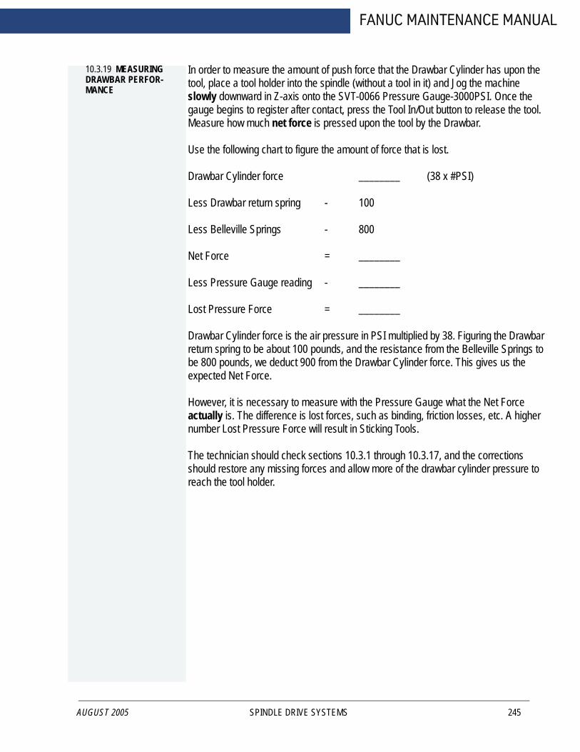
FANUC MAINTENANCE MANUAL
10.3.19 MEASURING DRAWBAR PERFOR-MANCE
AUGUST 2005
In order to measure the amount of push force that the Drawbar Cylinder has upon the tool, place a tool holder into the spindle (without a tool in it) and Jog the machine slowly downward in Z-axis onto the SVT-0066 Pressure Gauge-3000PSI. Once the gauge begins to register after contact, press the Tool In/Out button to release the tool. Measure how much net force is pressed upon the tool by the Drawbar.
Use the following chart to figure the amount of force that is lost.
Drawbar Cylinder force ________ (38 x #PSI)
Less Drawbar return spring - 100
Less Belleville Springs - 800
Net Force = ________
Less Pressure Gauge reading - ________
Lost Pressure Force = ________
Drawbar Cylinder force is the air pressure in PSI multiplied by 38. Figuring the Drawbar return spring to be about 100 pounds, and the resistance from the Belleville Springs to be 800 pounds, we deduct 900 from the Drawbar Cylinder force. This gives us the expected Net Force.
However, it is necessary to measure with the Pressure Gauge what the Net Force actually is. The difference is lost forces, such as binding, friction losses, etc. A higher number Lost Pressure Force will result in Sticking Tools.
The technician should check sections 10.3.1 through 10.3.17, and the corrections should restore any missing forces and allow more of the drawbar cylinder pressure to reach the tool holder.
SPINDLE DRIVE SYSTEMS 245

FADAL MACHINING CENTERS
10.3.20 DRB-0024 STICKING TOOLS KIT, 10K LDB, DRB-0025 STICKING TOOLS KIT, 10K LDB-CT=
246
Figure 10-17: Drawbar Kit
SPINDLE DRIVE SYSTEMS MAN-0121 R1

FANUC MAINTENANCE MANUAL
10.4 SPINDLE DRAWBAR AND BELLEVILLE SPRING REPLACEMENT
10.4.1 DRAWBAR REMOVAL
AUGUST 2005
1. Remove the Drawbar Cylinder Assembly.
2. Remove the Orientation Bridge Assembly.
3. Place a long 3/8 inch drive extension or similar item in the spindle and jog the headdown until the extension is under slight tension between the drawbar and the table.
WARNING!Do not place high tension on the extension; it only needs to support the drawbar. Place a piece of wood between the extension and the table, if needed.
4. Remove the Knock out cap (on locking drawbars only).
5. Place pilot tool on spring pilot.
6. Use wheel puller to depress the spring pilot.
7. Remove spring retainers.
8. Remove wheel puller.
9. Jog head up and remove the extension and the drawbar. Be careful not to drop theball bearing.
10. Now remove the belleville springs or the floater.
11. To reinstall, reverse the above steps.
10.4.2 REPLACE BELLEVILLE SPRINGS
1. Remove drawbar (See Drawbar Removal, Section 10.4.1, MAN-0121 R1)
2. Using a spring hook or a magnet remove the belleville springs (Be sure to removeany broken pieces).
3. Install replacement springs starting with first one cupped downward and reverseevery other one. The quantity will vary depending on the spindle pocket size (SeeBelleville Spring Quantity Chart, Table 10-1, MAN-0121 R1).
4. Reinstall drawbar.
SPINDLE DRIVE SYSTEMS 247

FADAL MACHINING CENTERS
10.4.3 REMOVE FLOATER
248
1. Remove the drawbar (See Drawbar Removal, Section 10.4.1, MAN-0121 R1)
2. The floater has two ball bearings that hold it in place. Using a floater removal tool ora magnet pull the ball bearing toward the center and the floater should come out. Ifbadly damaged the floater can be difficult to remove.
NOTE This procedure will rarely be necessary.Spindle Belleville Springs Quantity Chart
There have been many spindle and spring retainer combinations over the years. To determine the number of Belleville Springs in a spindle, three factors have to be considered: The depth of the spring pocket in the spindle, the depth of the spring retainer and the width of the Belleville springs. The following chart is a guide line for the number of springs and may vary slightly from spindle to spindle.
This chart covers the most common depths of spindles. In most cases the deeper spring retainers will use one less spring then number in the chart.
Table 10-1: Belleville Springs Quantity Chart
Spindle Type Spindle Depth
Number Of Springs
10K Non-Locking 2.00 1910K Non-Locking 3.00 3010K Non-Locking 4.25 4315K Non-Locking 4.326 4415K Non-Locking 4.627 4710K Locking 2.00 1810K Locking 3.00 2910K Locking 4.25 4210K Locking 4.326 4010K Locking 4.627 44
SPINDLE DRIVE SYSTEMS MAN-0121 R1

FANUC MAINTENANCE MANUAL
10.5 SPINDLE PRE-LOAD
10.5.1 MEASURING THE SPINDLE PRE-LOAD
AUGUST 2005
1. Place a Pressure Gage (SVT-0066) on the table and align it with the Spindle nose.
2. Set an indicator on the Head and touch the indicator tip on the nose of the Spindle.
3. Jog the head (Z axis) down until the pressure gage reads 1000 pounds.
4. Zero the Indicator.
5. Jog the head (Z axis) up until it is no longer in contact with the pressure gage.
6. Depress the “Tool In Out” Button on the keyboard.
7. Release Button.
8. Read the value on the indicator.
If adjustment is necessary on a adjustable spindle then turn the spindle preload adjustment nut clockwise to tighten and counter clockwise to loosen.
Listed below are the Fadal factory recommended specifications for the various spindles.
Table 10-2: Factory Recommended Spindle Specifications
RPM Rating Preload Setting (Deflection at 1,000 psi)
Lube Method
15,000/10,000 0014-.0017 (Can Not be adjusted) Air/Oil10,000 0013-.0015 (Adjustable preload) Grease Packed15,000 0017-.0019 (Adjustable preload) Grease Packed
SPINDLE DRIVE SYSTEMS 249

FADAL MACHINING CENTERS
10.6 SPINDLE DUTY CYCLE
250
The Fadal Engineering Department in conjunction with the bearing manufacturers recommend that the following procedures be followed to increase spindle life under extreme operating conditions.
Spindles operating under 8,000 RPMs need no cool down period regardless of on time or load to the tool.
Fadal recommends that spindles operating at over 8,000 RPMs for extended periods of time should be shut down for a period of at least 20 minutes after every 5 hours of continuous operation. This will allow cooling of the races and re-lubrication of the grease lubricated bearings. The actual load to the spindle is not a factor a these higher RPMs. The time period should be monitored as closely as possible to increase spindle life.
SPINDLE DRIVE SYSTEMS MAN-0121 R1
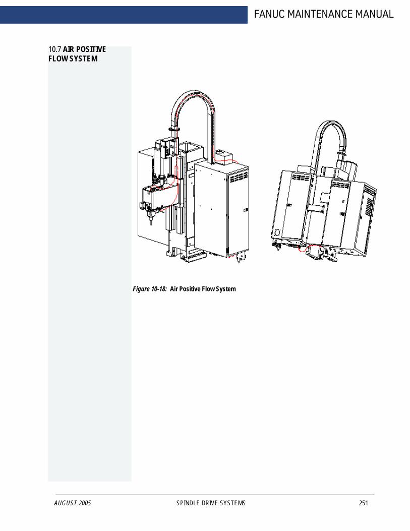
FANUC MAINTENANCE MANUAL
10.7 AIR POSITIVE FLOW SYSTEM
AUGUST 2005
Figure 10-18: Air Positive Flow System
SPINDLE DRIVE SYSTEMS 251
FADAL MACHINING CENTERS
10.8 SPINDLES
10.8.1 10K GREASE PACKED SPINDLES
252
Components
The 10K grease packed spindles are self contained units.
Functional Description
These spindles are belt driven and require no maintenance. There is air supplied to the spindle on the top and bottom for positive pressure.
These spindles are self-contained, therefore they should be replaced when bad. The 10K spindle has a locking drawbar.
10.8.2 15K AIR/OIL SPINDLE
Components
The 15K air/oil system consists of a spindle, a spindle lubricating oil supply pump, a vacuum pump, a positive displacement injector (PDI) block, a coalescent filter, four pressure switches (2-15psi, 1-80psi, 1-265psi) mounted on a pressure switch manifold, an electronic control board with wire harness, and various standard plumbing parts. This spindle is also belt driven.
Functional Description
The electronic control board controls the ON time of solenoids for oil and air while monitoring:
• Supply oil pressure• Oil reservoir level• Supply air pressure• Air/oil pressure to the upper and lower bearings of the spindle
The pump pressurizes oil to the PDI block. Oil pressure is monitored by an oil pressure switch. Air is supplied to the PDI block through a coalescing filter from a solenoid valve. Air pressure to the machine is monitored by an air pressure switch. The PDI block mixes air and oil. The two lines carry the air/oil mixture to the upper and lower bearings. The pressure of each line is monitored by a pressure switch. A vacuum pump is used to remove any oil that blows by the upper or lower bearings, to reduce oil leakage.
SPINDLE DRIVE SYSTEMS MAN-0121 R1

FANUC MAINTENANCE MANUAL
10.8.3 SPINDLE/LUBE PUMP/CONTROL
AUGUST 2005
Spindle
Bearings Ceramic Steel Hybrid
Lubrication Air and oil pressure feed back control
Operating temp. Ambient +20°F during steady state operation
Motor Power 15 HP
Max. Speed 15,000 RPM
Max. Cut 3/8”
Max. Depth of cut 3/8”
Max. Tool diameter 3/4”
Spindle Lube Pump
Lube Pump Air and oil feed back pressure control
Oil Mobil DTE 797 Steam Turbine Oil or equivalent
Oil Cycle Nominal 0.025 cc/injection cycle
Oil Filtration 5 micron absolute
Air Flow 160 SCFH @ 80 psi
Air Filtration 10 micron
Venturi Vacuum Pump 9" Hg
Control Circuit
Supply voltage 120 VAC
Overload protection 2 amp (fused)
Spindle Removal
1. Verify that the VMC is aligned with the cold start indicators.
2. Power off the VMC and lockout/tagout the main disconnect.
3. Disconnect the air supply from the VMC.
SPINDLE DRIVE SYSTEMS 253
FADAL MACHINING CENTERS
254
4. Remove the head cover by removing the four 1/4 -20 socket head cap screws.
5. Disconnect the electrical connection to the orientation bridge assembly at the sixpin connector plug.
6. Disconnect the two 1/4” air lines from the orientation bridge assembly.
7. Remove the draw bar cylinder plate by removing the six 1/4” hex head bolts and setthem aside.
8. Remove the orientation bridge assembly and the front belt guide by removing thethree 3/8” socket head cap screws.
9. To swing the spindle motor forward, loosen the 1/2” hex bolt on the left side of thespindle motor and loosen the two 1/2” hex bolts on the right side of the spindlemotor.
10. Remove the spindle drive belt.
WARNING!Use heavy duty work gloves when handling the heated spindle and pulley.
11. Using a propane torch, direct the flame at the spindle pulley for approximately 6-10minutes while slowly rotating the spindle. Maintain an even amount of heatthroughout the pulley. The spindle pulley will drop down on the spindle when it isexpanded enough to remove it from the spindle.
12. Label and disconnect the upper and lower spindle cooling lines from the spindle.Disconnect the 5/32” air seal line from the lower spindle flange. This will be reusedlater as the air supply to the vacuum pump.
13. Loosen the upper spindle retainer clamping screw.
14. Remove the six 1/2” hex bolts and lock washers from the upper spindle retainerand lift the retainer from the spindle. Ensure that the cooling line O-ring and thespindle O-ring are removed.
15. Remove the coolant supply manifold by removing the 1/4” socket head cap screw.Move it out of the work area and support it so that the lines are not crimped.
WARNING!Support the spindle with a wooden block while performing the next step.
16. Remove the six 3/8” socket head cap screws holding the spindle in the head,remove the old spindle and O-ring. Discard the used O-ring. Save the socket headcap screws.
SPINDLE DRIVE SYSTEMS MAN-0121 R1

FANUC MAINTENANCE MANUAL
10.8.4 COMPONENT INSTALLATION
AUGUST 2005
Regulator/ Separation Block Mounting
The regulator should be installed at the same location that it was at when the machine was originally installed.
Installing Spindle Lubrication Pump
Mount the spindle lubrication pump plate assembly to the side of the column above the way lube pump. On older model VMCs four 1/4-20 holes may need to be drilled and tapped; use the spindle lubrication pump plate assembly as a template.
Vacuum Pump Installation
Using the vacuum pump base as a template, drill through and tap two 1/4-20 holes into the left counter weight arm on top of the column. Mount the vacuum pump to the plate.
Pressure Manifold Mounting
Mount the pressure switch manifold block on the inside bottom of the cabinet, by removing the four knockouts and drilling the necessary mounting holes.
Control Board Mounting
Mount the control board on the inside upper right side of the cabinet, by drilling the necessary holes to attach.
Solenoid Modification
1. Remove the solenoid fitting on the solenoid closest to the rear of the cabinet.
2. Install the T-fitting and 1/4” to 5/32” reducer on solenoid.
10.8.5 SPINDLE TRAM
1. Level Machine.2. Adjust TABLE GIBS, SADDLE GIBS, and HEAD GIBS.
Watch for Turcite gibs:.0003"Non-Turcite gibs: .0005"
3. Adjust TABLE STRAPS.
4. Adjust SADDLE STRAPS and HEAD STRAPS.
SPINDLE DRIVE SYSTEMS 255
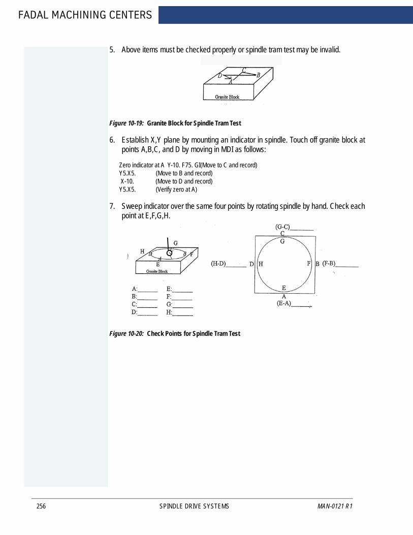
FADAL MACHINING CENTERS
256
5. Above items must be checked properly or spindle tram test may be invalid.
Figure 10-19: Granite Block for Spindle Tram Test
6. Establish X,Y plane by mounting an indicator in spindle. Touch off granite block atpoints A,B,C, and D by moving in MDI as follows:
Zero indicator at A Y-10. F75. GI(Move to C and record)Y5.X5. (Move to B and record) X-10. (Move to D and record)Y5.X5. (Verify zero at A)
7. Sweep indicator over the same four points by rotating spindle by hand. Check eachpoint at E,F,G,H.
Figure 10-20: Check Points for Spindle Tram Test
SPINDLE DRIVE SYSTEMS MAN-0121 R1
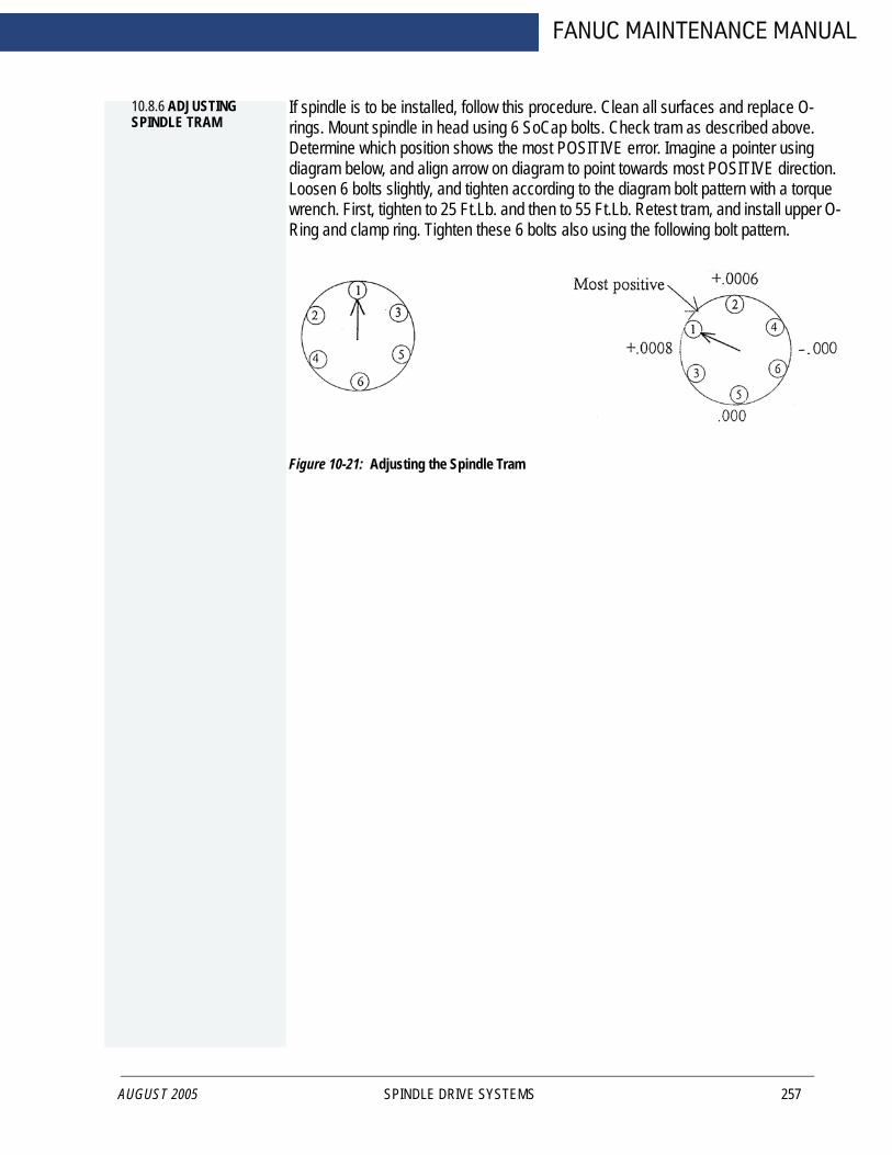
FANUC MAINTENANCE MANUAL
10.8.6 ADJUSTING SPINDLE TRAM
AUGUST 2005
If spindle is to be installed, follow this procedure. Clean all surfaces and replace O-rings. Mount spindle in head using 6 SoCap bolts. Check tram as described above. Determine which position shows the most POSITIVE error. Imagine a pointer using diagram below, and align arrow on diagram to point towards most POSITIVE direction. Loosen 6 bolts slightly, and tighten according to the diagram bolt pattern with a torque wrench. First, tighten to 25 Ft.Lb. and then to 55 Ft.Lb. Retest tram, and install upper O-Ring and clamp ring. Tighten these 6 bolts also using the following bolt pattern.
Figure 10-21: Adjusting the Spindle Tram
SPINDLE DRIVE SYSTEMS 257
FADAL MACHINING CENTERS
10.9 15K AIR/OIL SPINDLE INSTALLATION
258
1. Verify that the lower spindle O-ring is in good condition (not cut, torn or pinched).
2. Position the 15K spindle in the head with O-ring seal.
3. Install six socket head cap screws and evenly tighten them until they are snug.Torque the socket head cap screws in increments of 25 ft/lbs then 40 ft/lbs.
4. Place a magnetic dial indicator base on the spindle. Check the run out on a trueplate. The run out should be less than .0005"(.0127mm).
5. Shim the spindle if necessary to achieve a proper run out specification.
6. Verify that the upper spindle retainer O-rings are in good condition (not cut, torn orpinched).
7. Align the upper spindle retaining ring with the cooling passage. Lightly cover thehex head bolts with gasket sealing compound and evenly tighten them until snug.Torque the hex head bolts to 30 ft/lbs.
8. Snugly tighten the retainer ring clamping screw.
9. Using a propane torch, direct the flame at the spindle pulley for approximately 5minutes. Maintain an even amount of heat throughout the spindle pulley.
WARNING!Use heavy duty work gloves when handling the heated spindle and spindle pulley.
10. While the spindle pulley is heating, place the spindle pulley locating spacer (part #SVT-0096) on the ground surfaces of the head.
11. Find the orientation mark on the top of the spindle housing and position the spindleso that the orientation mark is toward the front of the VMC. Secure the spindle sothat it will not rotate when installing the spindle pulley.
12. Place the spindle pulley on the spindle so that it rests on the locating spacer, at thesame time align the orientation marks of the spindle and the spindle pulley.
13. Allow the spindle pulley to cool to the touch before continuing with the assembly.
14. Install the spindle drive belt.
15. Place a dial indicator against the top front edge of the pulley and set it at zero.
16. Swing the spindle motor towards the rear of the machine until the dial indicatorreads .0003" (.0076mm).
WARNING!Do not adjust the belt tension more than the recommended deflection.
17. Tighten the 1/2” hex bolt on the left side of the spindle motor and the two 1/2” hexbolts on the right side of the spindle motor.
SPINDLE DRIVE SYSTEMS MAN-0121 R1
AUGUST 2005
FANUC MAINTENANCE MANUAL
18. Install the orientation bridge assembly and front belt guide with the three 3/8”socket head cap screws, and tighten them snugly.
19. Install the draw bar cylinder plate with the six hex head bolts, and tighten the bolts.
20. Connect the six pin connector plug into the orientation bridge assembly.
21. Connect the two 1/4” air lines to the orientation bridge.
22. Connect the coolant lines removed from the old spindle to the upper and lowerconnections on the new spindle.
10.9.1 PLUMBING SPINDLE
1. Pull four 5/32” air lines from the back of the machine up through the cable ways to apoint just above the head next to the motor mounts. Leave a portion of the linescoiled for extra.
NOTE Check the machine for the High/Low option 5/32” lines. If these lines are present they can be used instead of pulling the new lines through the cable ways. Label these lines as 21, 22, 25 and 26 if used.
2. Pull the 5/32” air seal line previously removed from the old spindle up through thecable way. Connect it to the fitting (32) on the vacuum pump.
3. Insert three 5/32” lines in 3 foot lengths into the fittings located on the lower spindleflange. The three lines are the inlet line stamped “AIR/OIL IN” (23), the exhaust linestamped “AIR OUT” (29), and the vacuum line stamped “VACUUM” (27).
4. Cover the two lines (23, 27) with 1/4” nylon tubing from the fittings to the pointwhere they enter the head.
5. Feed the line from the fitting on the lower flange stamped with “AIR/OIL IN” (23) upthrough the head to where the four lines are located next to the motor mount.
6. Insert three 5/32” lines in 3 foot lengths into the three fittings located on the upperbearing retainer just below the pulley. The three lines are the inlet line stamped“AIR/OIL IN” (24), the exhaust line stamped “AIR OUT” (30), and the vacuum linestamped “VAC/AIR” (28).
7. Feed the inlet line, stamped “AIR/OIL IN” (24) on the upper bearing retainer, intothe head and up along side the other lines from the lower flange.
8. The four lines coming to the head from the back of the machine are two PDI lines(21, 22) and two Pressure switch lines (25, 26). Be sure to keep these lines labeled.
9. Connect one air/oil PDI line (21) and one pressure switch line (25) to the doubleend of the Y-fitting.
SPINDLE DRIVE SYSTEMS 259
FADAL MACHINING CENTERS
260
10. Connect the inlet line, stamped “AIR/OIL IN” (23) on the lower flange, to the singleend of the Y-fitting.
11. Connect the other air/oil PDI line (22) and the other pressure switch line (26) to thedouble end of the second Y-fitting.
12. Connect the inlet line, stamped “AIR/OIL IN” (24) on the upper bearing retainer, tothe single end of the Y-fitting.
13. Feed the two outlet lines, one from the lower flange Stamped “AIR OUT” (29) andone from the upper bearing retainer stamped “AIR OUT” (30), into the inside of thehead and fasten them to any hose with a nylon wire tie. These two lines are theexhaust lines.
14. Verify that a 5-in-line valve system or air-seal valve is installed on the machine. Ifthey currently do not exist on the machine, order and install part number VLV-0006.
15. Feed the lower vacuum line (27) up through the head to the vacuum pump andconnect it to the Y-fitting (27) on the vacuum pump.
16. Feed the upper vacuum line (28) along the top of the head to the vacuum pumpand connect it to the fitting (28) on the vacuum pump.
17. Verify that all plumbing lines are installed correctly. Secure loose lines asnecessary with nylon wire ties.
10.9.2 INSTALL COM-PONENT PLUMBING
1. Complete the installation of all lines for the air supplies, oil supply lines andpressure feed back lines.
2. Before filling the spindle lubrication pump with the recommended oil (Mobil DTE797 Steam Turbine Oil), remove the reservoir and inspect the float on the levelswitch. The cutaway ridge on the float should be on top. Remove the float andreverse it if the ridge is on the bottom of the float.
Start Up After Installation
1. Fill the reservoir on the spindle lube tank with Mobil DTE 797 ISOVG32 oil orequivalent. Any other viscosity oil will cause damage to the spindle.
2. Check the wiring on the circuit control board.
3. Plug in the air supply line to the machine and set the regulators to 80 psi for the leftregulator and 120 psi for the right regulator.
4. Remove the oil pressure line from the oil pressure switch fitting on the pressureswitch manifold. Hold the line over a collecting container. Prime the spindlelubricating pump by depressing the solenoid button with a small screwdriver until allair bubbles are removed from the oil pressure line.
SPINDLE DRIVE SYSTEMS MAN-0121 R1

AUGUST 2005
FANUC MAINTENANCE MANUAL
NOTE Observe the color of the oil coming out of the oil pressure line. If the color is DARK BROWN, there is way lube oil in the pump. Prime the line until the way lube oil is flushed out. The spindle oil color is LIGHT YELLOW, prime the oil pressure line until the oil coming out is this color.
5. Replace the oil pressure line at the oil pressure switch fitting.
6. Press the reset button on the control board and observe the LED lights (if any lightsare illuminated then take the action necessary to correct the condition).
7. Prime the PDI block with the spindle inlet lines at the Y-fitting on the headdisconnected. Prime until oil is seen flowing through both of the 5/32” lines comingout of the PDI block. Prime by pressing the spindle lubrication pump solenoidbutton with a small screwdriver. Press it for 10 seconds and release it for 10seconds and repeat until oil flow is satisfactory. Priming can only be done while theair is flowing to the spindle. If air is not flowing then press and release the resetbutton. This will provide 2 minutes of air flow.
8. After priming the PDI block, run the spindle at 10,000 RPM and monitor thetemperature for 20 minutes. If the temperature is high, check the PDI blockoperation.
9. Run the spindle at 15,000 RPM and monitor the temperature. The spindletemperature should be below 100°F after one-half hour. This is the steady-statetemperature of the spindle.
10. If the temperature exceeds this specification, verify the oil line connections and theoiling cycle.
SPINDLE DRIVE SYSTEMS 261
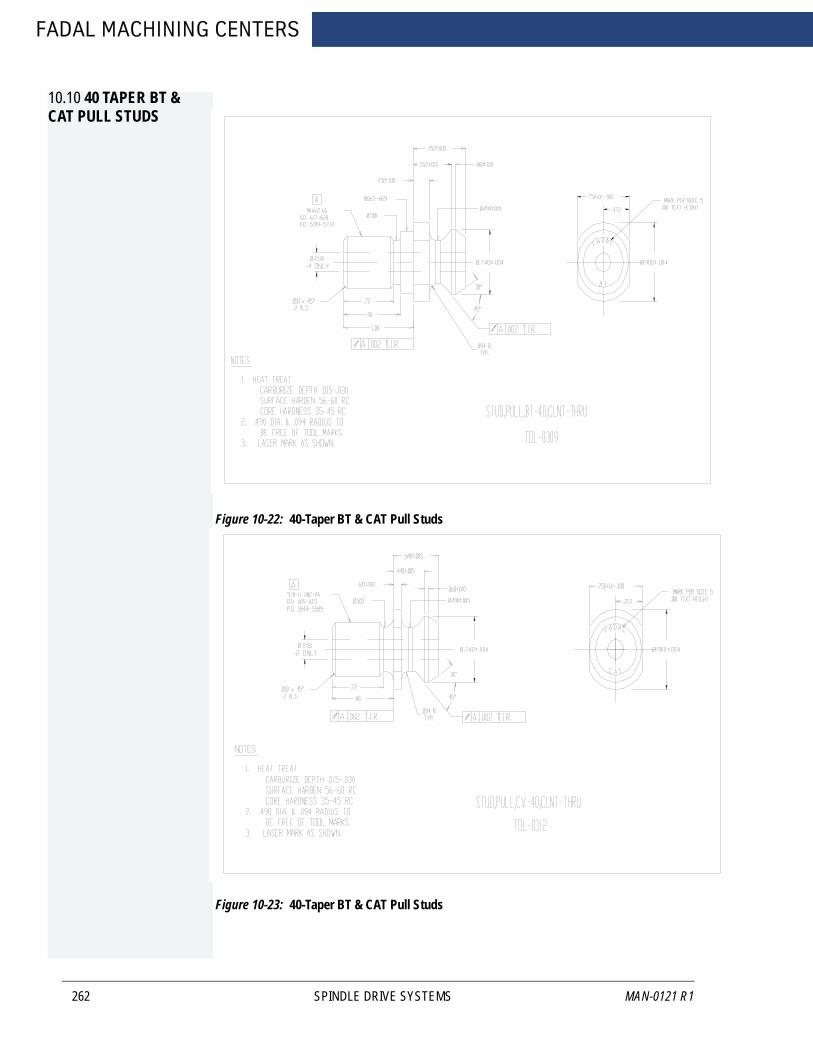
FADAL MACHINING CENTERS
10.10 40 TAPER BT & CAT PULL STUDS
262
Figure 10-22: 40-Taper BT & CAT Pull Studs
Figure 10-23: 40-Taper BT & CAT Pull Studs
SPINDLE DRIVE SYSTEMS MAN-0121 R1

FANUC MAINTENANCE MANUAL
AUGUST 2005
11.0 FUSES
Before replacing a blown fuse, it is necessary to locate and remove the cause of the blown fuse.
For this reason, only those personnel who have received approved safety and maintenance training may perform this work.
WARNING!Before starting the replacement of a fuse, remove the cause of the fuse butn-out. Accordingly, the replacement should be performed by a person fully trained in maintenance of safety. When replacing a fuse with the cabinet open, be careful not to touch the high-voltage circuits. Touching an uncovered high-voltage circuit pre-sents an extremely dangerous electric shock hazard.
FUSES 263
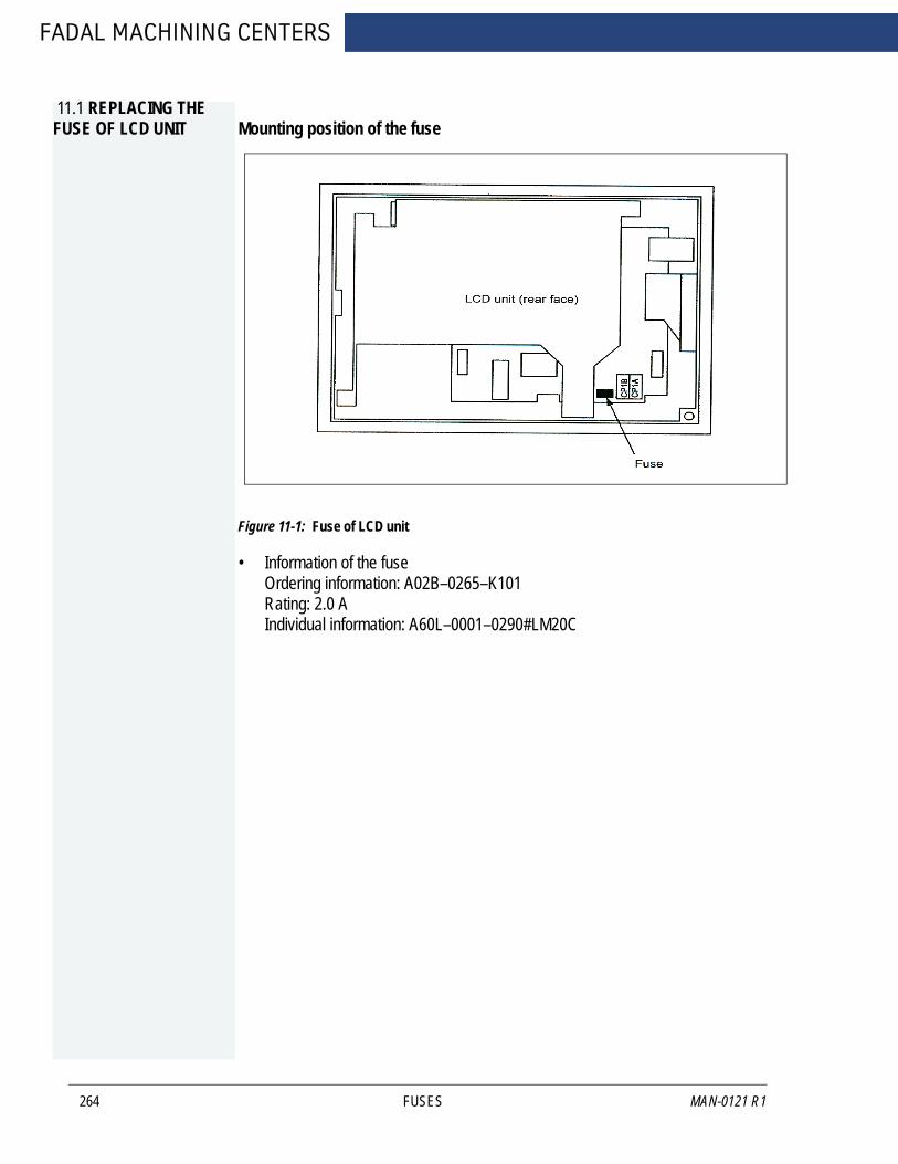
FADAL MACHINING CENTERS
11.1 REPLACING THE FUSE OF LCD UNIT
264
Mounting position of the fuse
Figure 11-1: Fuse of LCD unit
• Information of the fuse Ordering information: A02B–0265–K101 Rating: 2.0 A Individual information: A60L–0001–0290#LM20C
FUSES MAN-0121 R1

FANUC MAINTENANCE MANUAL
11.2 PANEL FUSES
AUGUST 2005
Fuses are GMA-1, GMA-2, GMA-3, GMA-5.
Location
Table 11-1: Panel Fuses
TERMINAL BLOCK
POSITION FUSE
T.B.1 180F1 24V 5AMP180F2 24V 3AMP180F3 24V 1AMP180F4 24V 5AMP
T.B.3 170FU1 120V 2AMP170FU2 120V 2AMP170FU3 120V 2AMP173FU1 120V 3AMP
T.B.4 850FU1 24V 1AMP850FU2 24V 1AMP850FU3 24V 1AMP850FU4 24V 1AMP850FU5 24V 1AMP850FU6 24V 1AMP850FU7 24V 1AMP850FU8 24V 1AMP851FU1 24V 1AMP851FU2 24V 1AMP851FU3 24V 1AMP851FU4 24V 1AMP851FU5 24V 1AMP851FU6 24V 1AMP851FU7 24V 1AMP851FU8 24V 1AMP852FU1 24V 1AMP852FU2 24V 1AMP852FU3 24V 1AMP852FU4 24V 1AMP852FU5 24V 1AMP852FU6 24V 1AMP852FU7 24V 1AMP852FU8 24V 1AMP853FU1 24V 2AMP853FU2 24V 2AM853FU3 24V 2AMP853FU4 24V 2AMP
FUSES 265
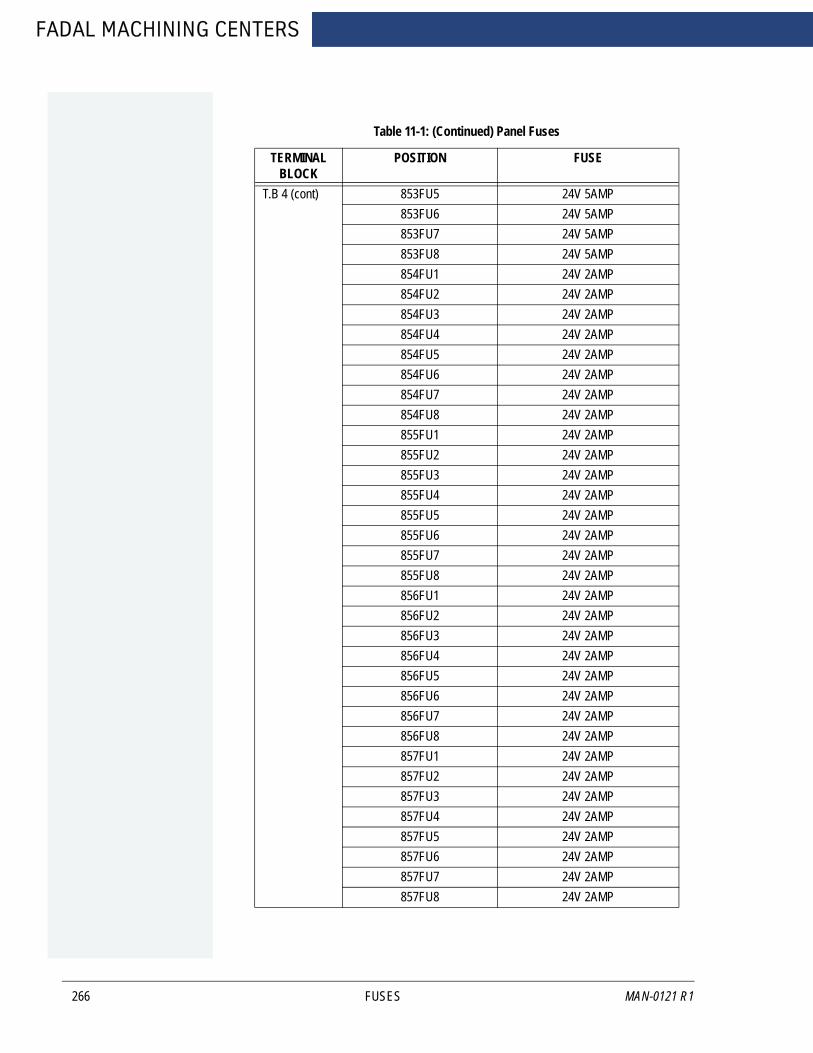
FADAL MACHINING CENTERS
266
Table 11-1: (Continued) Panel Fuses
TERMINAL BLOCK
POSITION FUSE
T.B 4 (cont) 853FU5 24V 5AMP853FU6 24V 5AMP853FU7 24V 5AMP853FU8 24V 5AMP854FU1 24V 2AMP854FU2 24V 2AMP854FU3 24V 2AMP854FU4 24V 2AMP854FU5 24V 2AMP854FU6 24V 2AMP854FU7 24V 2AMP854FU8 24V 2AMP855FU1 24V 2AMP855FU2 24V 2AMP855FU3 24V 2AMP855FU4 24V 2AMP855FU5 24V 2AMP855FU6 24V 2AMP855FU7 24V 2AMP855FU8 24V 2AMP856FU1 24V 2AMP856FU2 24V 2AMP856FU3 24V 2AMP856FU4 24V 2AMP856FU5 24V 2AMP856FU6 24V 2AMP856FU7 24V 2AMP856FU8 24V 2AMP857FU1 24V 2AMP857FU2 24V 2AMP857FU3 24V 2AMP857FU4 24V 2AMP857FU5 24V 2AMP857FU6 24V 2AMP857FU7 24V 2AMP857FU8 24V 2AMP
FUSES MAN-0121 R1
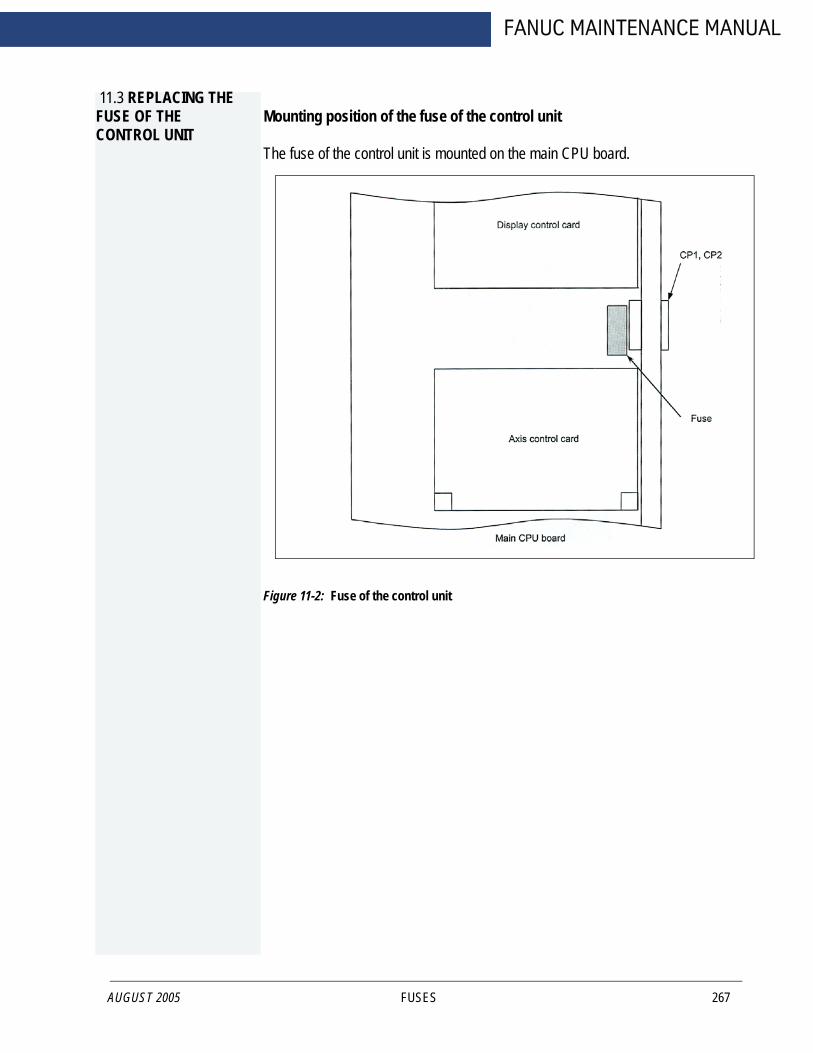
FANUC MAINTENANCE MANUAL
11.3 REPLACING THE FUSE OF THE CONTROL UNIT
AUGUST 2005
Mounting position of the fuse of the control unit
The fuse of the control unit is mounted on the main CPU board.
Figure 11-2: Fuse of the control unit
FUSES 267
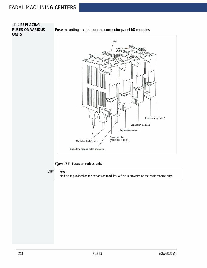
FADAL MACHINING CENTERS
11.4 REPLACING FUSES ON VARIOUS UNITS
268
Fuse mounting location on the connector panel I/O modules
Figure 11-3: Fuses on various units
NOTE No fuse is provided on the expansion modules. A fuse is provided on the basic module only.
FUSES MAN-0121 R1

AUGUST 2005
FANUC MAINTENANCE MANUAL
Fuse mounting location on the operator’s panel I/O modules
Figure 11-4: Fuse on the operator’s panel
Fuse mounting location on the operator’s panel connection units
Figure 11-5: Fuse on the operator’s panel
FUSES 269
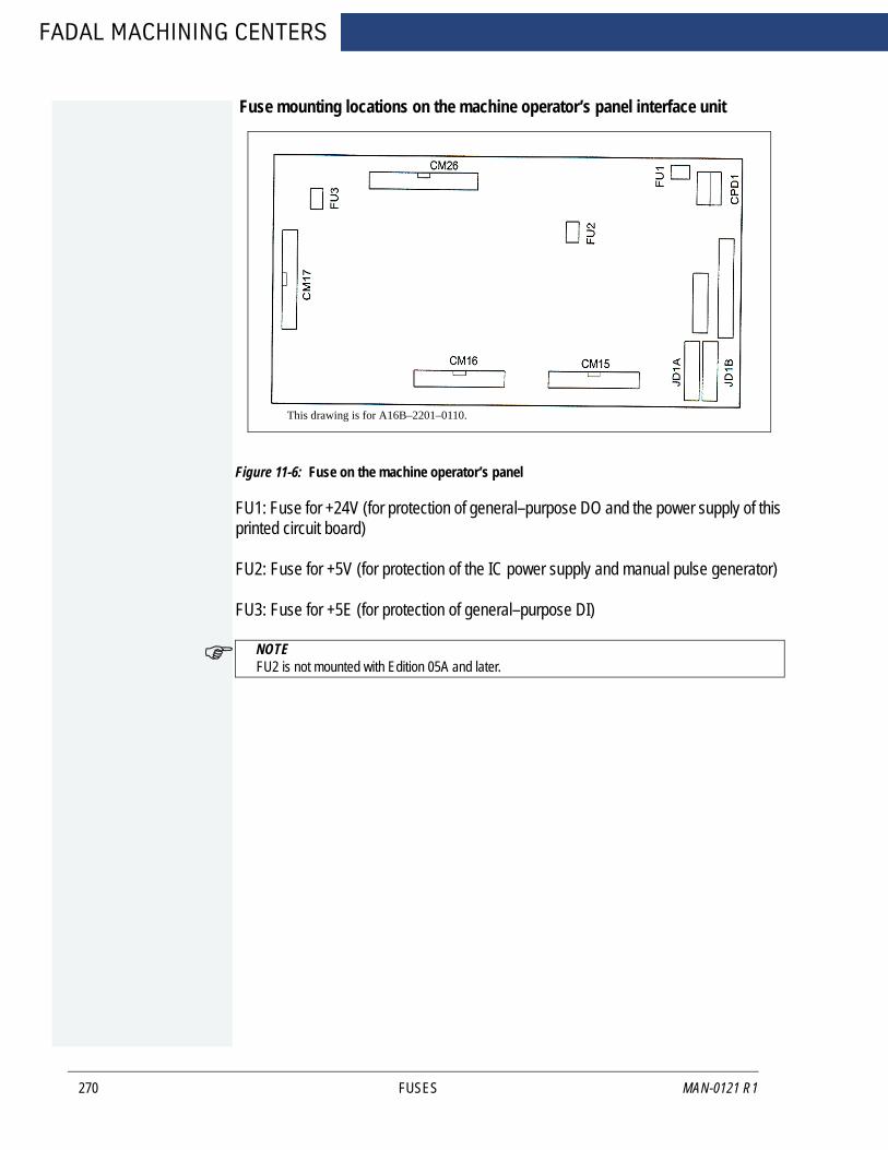
FADAL MACHINING CENTERS
270
Fuse mounting locations on the machine operator’s panel interface unit
Figure 11-6: Fuse on the machine operator’s panel
FU1: Fuse for +24V (for protection of general–purpose DO and the power supply of this printed circuit board)
FU2: Fuse for +5V (for protection of the IC power supply and manual pulse generator)
FU3: Fuse for +5E (for protection of general–purpose DI)
NOTE FU2 is not mounted with Edition 05A and later.
This drawing is for A16B–2201–0110.
FUSES MAN-0121 R1

AUGUST 2005
FANUC MAINTENANCE MANUAL
Fuse mounting location on the distributed I/O machine operator’s panels
Figure 11-7: Fuse the distributed I/O panel
Fuse mounting location on the separate detector interface unit
Figure 11-8: Fuse on the separate ditector
FUSES 271

FADAL MACHINING CENTERS
272
FUSES MAN-0121 R1
FANUC MAINTENANCE MANUAL
AUGUST 2005
12.0 GENERAL INFORMATION
12.0 GENERAL INFORMATION 273
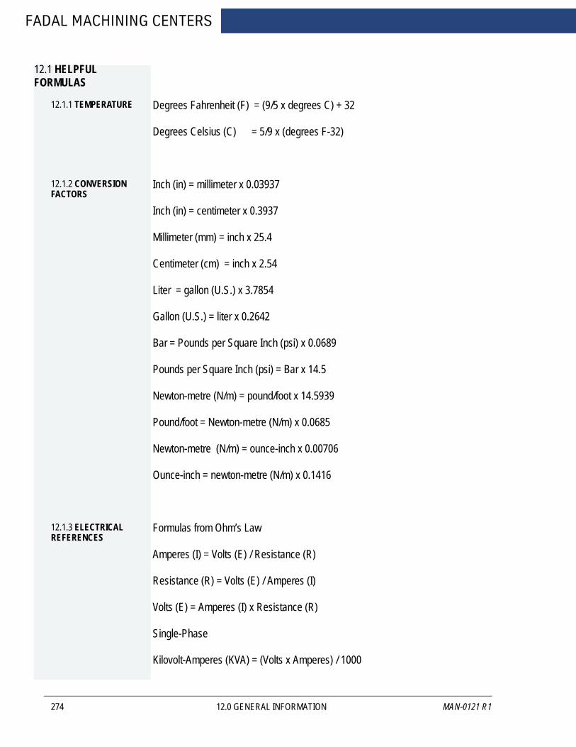
FADAL MACHINING CENTERS
12.1 HELPFUL FORMULAS
12.1.1 TEMPERATURE
274
Degrees Fahrenheit (F) = (9/5 x degrees C) + 32
Degrees Celsius (C) = 5/9 x (degrees F-32)
12.1.2 CONVERSION FACTORS
Inch (in) = millimeter x 0.03937
Inch (in) = centimeter x 0.3937
Millimeter (mm) = inch x 25.4
Centimeter (cm) = inch x 2.54
Liter = gallon (U.S.) x 3.7854
Gallon (U.S.) = liter x 0.2642
Bar = Pounds per Square Inch (psi) x 0.0689
Pounds per Square Inch (psi) = Bar x 14.5
Newton-metre (N/m) = pound/foot x 14.5939
Pound/foot = Newton-metre (N/m) x 0.0685
Newton-metre (N/m) = ounce-inch x 0.00706
Ounce-inch = newton-metre (N/m) x 0.1416
12.1.3 ELECTRICAL REFERENCES
Formulas from Ohm’s Law
Amperes (I) = Volts (E) / Resistance (R)
Resistance (R) = Volts (E) / Amperes (I)
Volts (E) = Amperes (I) x Resistance (R)
Single-Phase
Kilovolt-Amperes (KVA) = (Volts x Amperes) / 1000
12.0 GENERAL INFORMATION MAN-0121 R1

AUGUST 2005
FANUC MAINTENANCE MANUAL
Three-Phase
Kilovolt-Amperes (KVA) = (Volts x Amperes x 1.73) / 1000
12.1.4 EXPANSION COEFFICIENTS
Formula
Expansion amount =
Coefficient x distance x degree of temperature change (Fahrenheit)
Coefficients
Steel = .00000633
Cast Iron = .00000655
Aluminum = .00001244
pathname = C:\CNCDATA\
filename = PN1234.NC
> = > (the > is required DOS syntax to redirect file to COM2)
port = COM2
NOTE Before typing these two lines, the VMC should be in the TA,1 mode ready to receive the program at 2400 baud.Refer to the DOS manual for answers to additional questions about the DOS commands used here.Running DOS-based software from Windows may not work for communications.
12.0 GENERAL INFORMATION 275
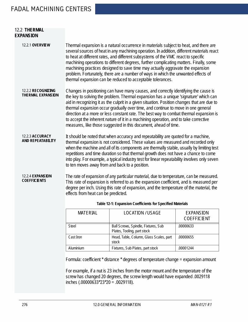
FADAL MACHINING CENTERS
12.2 THERMAL EXPANSION
12.2.1 OVERVIEW
276
Thermal expansion is a natural occurrence in materials subject to heat, and there are several sources of heat in any machining operation. In addition, different materials react to heat at different rates, and different subsystems of the VMC react to specific machining operations to different degrees, further complicating matters. Finally, some machining practices designed to save time may actually aggravate the expansion problem. Fortunately, there are a number of ways in which the unwanted effects of thermal expansion can be reduced to acceptable tolerances.
12.2.2 RECOGNIZING THERMAL EXPANSION
Changes in positioning can have many causes, and correctly identifying the cause is the key to solving the problem. Thermal expansion has a unique 'signature' which can aid in recognizing it as the culprit in a given situation. Position changes that are due to thermal expansion occur gradually over time, and continue to move in one general direction at a more or less constant rate. The best way to combat thermal expansion is to accept the inherent nature of it in a machining operation, and to take corrective measures, like those suggested in this document, ahead of time.
12.2.3 ACCURACY AND REPEATABILITY
It should be noted that when accuracy and repeatability are quoted for a machine, thermal expansion is not considered. These values are measured and recorded only when the machine and all of its components are thermally stable, usually by limiting test repetitions and time duration so that thermal growth does not have a chance to come into play. For example, a typical industry test for linear repeatability involves only seven to ten moves away from and back to a position.
12.2.4 EXPANSION COEFFICIENTS
The rate of expansion of any particular material, due to temperature, can be measured. This rate of expansion is referred to as the expansion coefficient, and is measured per degree per inch. Using this rate of expansion, and the temperature of the material, the effects from heat can be predicted.
Formula: coefficient * distance * degrees of temperature change = expansion amount
For example, if a nut is 23 inches from the motor mount and the temperature of the screw has changed 20 degrees, the screw length would have expanded .0029118 inches (.00000633*23*20 = .0029118).
Table 12-1: Expansion Coefficients for Specified Materials
MATERIAL LOCATION / USAGE EXPANSION COEFFICIENT
Steel Ball Screws, Spindle, Fixtures, Sub Plates, Tooling, part stock
.00000633
Cast Iron Head, Table, Column, Glass Scales, part stock
.00000655
Aluminium Fixtures, Sub Plates, part stock .00001244
12.0 GENERAL INFORMATION MAN-0121 R1

FANUC MAINTENANCE MANUAL
12.2.5 HEAT SOURCES
AUGUST 2005
It comes as no surprise that the primary source of heat in machining is friction; however, some of the sources of friction, and all of the areas affected by a given friction source, may not be readily apparent. Additionally, the effects on the ambient temperature from various heat sources in the machine shop are often overlooked.
12.2.6 FRICTION
The most obvious heat source from friction is the cutting of material itself. Heat is transferred to the chips, which then can transfer their heat to the table. Heat is also transferred to the tool, and then to the spindle, and then to the head. Finally, heat is transferred to the part material itself, and from there to any fixture or sub plate holding the blank.Movement of the table, and of the head, also generates heat from the friction. The ball screws turning produces friction between the nut and the screw, heating the screw and causing expansion, with the Y axis of the machine experiencing more thermal expansion than the X axis because the Y axis is moving more weight than the X axis. The movement of the table on the ways produces friction which can increase the expansion of the ball screws.
12.2.7 AMBIENT TEM-PERATURE
The general temperature of the shop environment will affect the machining process, but the most significant effect will be seen when temperature differences are created. Sunlight on a VMC will cause the side of the machine in the sun to expand at a different rate than the side in the shade. Radiant heat sources, such as ovens or hydraulic pumps, will heat the side of the VMC closest to them significantly more than the side furthest from the radiant heat source, causing uneven expansion. Cooling vents without diffusion gratings can blow cooler air onto one area of the VMC than another area, once again causing uneven expansion.
The goal is to surround everything with an even temperature. A shop at 90 degrees will experience more thermal expansion than a shop at 70 degrees, but a shop at 70 degrees with an air conditioning vent blowing directly on the VMC will experience more problems with uneven thermal expansion.
12.2.8 MACHINING PRACTICES
There are a few machining practices that can aggravate thermal expansion, or its perceived effects, and deserve special mention. One is the use of rapid moves in a CNC program, which can vastly increase the friction, and therefore the thermal expansion, on the ball screws. The obvious drawback of reducing rapid moves is a slower production rate, however, this may be compensated for by increased accuracy and reduced scrap rates.
Another practice is using ceramic (or other) cutters without coolant and allowing the chips to sit on the table. The chips absorb the majority of the heat from the cutting process, and then transfer this heat to the table, causing the table to expand independently from any other part of the VMC.
A third practice is the use of cutting oil in place of water-soluble coolant. Although cutting oil does reduce friction at the surface of the cut, coolant does a much better job
12.0 GENERAL INFORMATION 277

FADAL MACHINING CENTERS
278
of carrying away the heat of the cut and minimizing the effects of thermal expansion resulting from that heat.
Yet another practice that deserves mentioning is machining parts at temperatures significantly different from those at which the parts are inspected. If the inherent expansion of the part material from the heat of the machining process is outside tolerance once the part has cooled to inspection temperatures, the problem can only be resolved by correcting for the heat generated during machining so as to keep the part material closer to inspection temperatures while the part is being machined. Along those same lines, it is important to use a gauge at approximately the same temperature as the temperature at which the gauge was calibrated.
Finally, the use of blanks for which the outside dimensions have been established prior to cutting is another practice which aggravates the effects of thermal expansion. Since the blank is going to expand locally from the heat of cutting, the actual distance from edge to feature may change.
12.0 GENERAL INFORMATION MAN-0121 R1

FANUC MAINTENANCE MANUAL
12.3 NON-UNIFORM EXPANSION
12.3.1 MATERIAL DIFFERENCES
AUGUST 2005
The differing rates of expansion by unlike materials further complicate the problems created by the heat generated in the machining process. This applies both to parts stock, like aluminum, and to fixtures and sub plates, often also made of a material like aluminum. Aluminum's coefficient of expansion is nearly twice that of steel or cast iron (the primary VMC materials), which means the aluminum will expand nearly twice as much as the ball screws, head, spindle, or table.
12.3.2 FIXTURES / SUB PLATES
Fixtures or sub plates of material other than the steel/cast iron of the VMC will cause the greatest problems in this area, unless the bottom of the fixture or sub plate is flat within .001° (please note that "parallel" is not the same as "flat", and flatness is the key in this area). For example, a sub plate made of aluminum has an expansion coefficient nearly double that of the table to which it is secured. If the flatness is not within. 001", the heat of the machining process causing the sub plate to expand at twice the rate of the table will result in the sub plate actually bending the VMC's table. This will cause binding which will both affect position accuracy and cause undue wear on the mating surfaces under the table.
12.3.3 MACHINE ASSEMBLIES
Various assemblies of the VMC itself will be affected by different sources of heat in the machining process, and the effect of each assembly on positioning will vary accordingly.
For instance, the head will expand from two heat sources, the spindle heat and the ambient temperature. The effects of thermal expansion in the head will be seen in the directions of the Y axis and the Z axis, but not in the X axis, with the Y axis expanding away from the column (toward the operator) and the Z axis expanding down toward the table. Meanwhile, the Y axis itself will be expanding away from the column due to the expansion of the ball screw, which will compensate for the effect of the head's expansion in the same direction.
The ball screws will expand due to the friction of the nut. The effect will
increase with the distance of the nut from the motor mounts (the effective length of the screw), and will be in the direction away from the motor mounts. Thermal growth of the ball screws is independent of growth in the head or the table.
The spindle experiences heat not only from the actual cutting, which is transferred through the tool, but also from its bearings. The spindle also transfers most of this heat to the head, and the thermal growth is reflected in the head position, as mentioned above, and is independent of changes in the ball screws or table.
The table receives most of its heat secondhand, through the heat of the nut, the heat from the part (through the fixture or sub plate), and the heat carried by hot chips that lay
12.0 GENERAL INFORMATION 279

FADAL MACHINING CENTERS
280
on the table. Because of its large size, the table seems less affected by the heat of machining. It will expand, but it takes longer to heat or cool the entire table. In addition, the use of coolant tends to stabilize the temperature of the table at or close to coolant temperature.
A machining operation using rapid moves and low spindle speeds, with additional cooling at the part through FADAL's servo coolant subsystem, will generate much more thermal expansion in the ball screws, and hence the X axis and Y axis, than will be seen in the Z axis from the spindle or in the part material from the cutting. An operation using very high RPM spindle speeds with slower interpolated moves would experience more Z axis expansion, but would experience less expansion in the X axis and Y axis, and might actually experience less expansion in the part material because the high rate of chip removal carries much of the heat away from the part.
Each machining operation has a unique combination of factors that apply to predicting and managing the thermal expansion inherent in machining. Finding the right solution is a matter of combining various approaches, many of which are outlined in the pages that follow.
12.0 GENERAL INFORMATION MAN-0121 R1

FANUC MAINTENANCE MANUAL
12.4 SOLVING THE THERMAL EXPANSION PROBLEM
12.4.1 GENERAL CONSIDERATIONS
AUGUST 2005
A simplified description of the thermal environment in machining would state that heat is generated through friction, and also input through ambient factors. That heat is transferred among the system components, and is either removed from the system through radiation, convection and evaporation, or absorbed by the components of the system (part, fixture, VMC).
In its simplest form, any solution designed to combat thermal expansion must reduce friction, reduce ambient influences, or increase heat removal through radiation, convection or evaporation. A complementary approach is to simply compensate for the changes brought on by thermal expansion. In a real life situation, a balance of approaches is required.
12.4.2 AMBIENT SOURCES
Sunlight
Do not allow direct sunlight on the VMC. Window shades that diffuse sunlight can be acceptable, but any source of warmth that only heats one side of the VMC at a time will cause uneven warming and further complicate thermal considerations.
Cooling Systems
Diffusion gratings on air conditioning vents can be used to prevent any air from directly blowing on the machine or part. Again, an unevenly heated part or machine will cause the heated, or cooled, portion of the part or machine to expand at rates different from the rest of the part or machine.
Radiant Heat
If an operator can detect the radiant heat from other devices, a protective wall needs to be erected between the machine and the device radiating the heat. This type of heat source will cause the machine to heat up on one side and cause uneven expansion.
12.0 GENERAL INFORMATION 281

FADAL MACHINING CENTERS
12.5 READING STATUS GROUP
282
Reading a status in a computer can be very helpful for troubleshooting. Status is usually a byte or a word. The status is normally represented in hexadecimal. To demonstrate how a status byte is decoded, the command 1 byte in the diagnostics – display switches will be used. Each binary bit in the status byte will represent one relay in this case. Because Fadal uses negative logic, a value of zero (0) turns the relay on (activates it). B0 is the right-most bit. Each Hexadecimal digit is representing four (4) binary bits.
B0 = M68/M69
B1 = High range Idler
B2 = Unused
B3 = Drawbar / Geneva / Slide Enable
B4 = Drawbar
B5 = Air indexer
B6 = Coolant 1 On
B7 = Coolant 2 On
For example if the command 1 displayed “BD” then the binary equivalent would be “1 0 1 1 1 1 0 1”. To decode remember that “0” is On. In this example, B1 the high range idler would be On and Coolant 1 would be On.
12.0 GENERAL INFORMATION MAN-0121 R1
FANUC MAINTENANCE MANUAL
12.6 VMC MAINTENANCE
12.6.1 CABINET FANS
AUGUST 2005
The fans in the cabinets must be functioning properly. The purpose of the fans in the cabinets is to cool the electronics and to move the heat out the vents. An excessive amount of heat in the cabinets, from clogged holes or nonfunctional fans, will transfer to the column and cause it to expand, as well as damaging the electronics. On a regular basis, remove and clean the vent hole grates, as the vents occasionally become clogged with dust or other particles, and inspect the fans to see that they are working.
12.6.2 LUBRICATION
Lubrication is essential for the free motion of the table, saddle, and head, as well as for the nut on each ball screw. Each way must be lubricated, and the ball screws greased, to minimize both the wear on the machine and the excess heat generated by friction. The lubrication system must be inspected and serviced regularly. Inspect all of the ways to confirm that each way is getting lubricated. The lubrication system may need to be flushed by a qualified service person to remove any contaminants on the inside of the tubes and joints.12.6.3 MACHINING PRACTICES
Warm Up
The first step in combating thermal expansion effects is also the simplest. Run the machine through a series of moves, at feeds and speeds equivalent to what will be encountered in the production run, long enough to reach an equilibrium; that is, where the amount of heat being generated is balanced by the amount of heat being removed (via convection, evaporation, or absorption through expansion of material). After that point is reached, the effect of thermal expansion in the VMC stabilizes, and the only corrections needed are for the expansion of the part material as each successive part feature is machined.
Locate fixture offsets and establish tool length offsets after the machine has attained the optimum operating temperature. Avoid using moves or spindle speeds that exceed those used in the part program.
In addition to running a warm up routine at the beginning of the production shift, the same kind of routine can be run during breaks. This will maintain the VMC at operating temperature, especially the two subsystems that heat up or cool down the most (the spindle and the ball screws).
Rough Cut / Cool Down / Finish Cut
A complement to the warm up of the VMC is the use of a rough cut to remove most of the material from the part. Although the part material heats up, the material can then be cooled to a stable temperature. Then, a series of finish cuts can complete the part in a short time, so that the material doesn't have time to expand beyond acceptable tolerance.
12.0 GENERAL INFORMATION 283

FADAL MACHINING CENTERS
284
This process is also effective for inspecting parts. By cooling the part prior to the finish cuts, the temperatures at final cut and at inspection can be brought closer. In this situation, the target temperature should also be close to the temperature at which the gauge is calibrated.
Monitoring Position Changes
The home position of the part will change as the temperature of the screws change. The operator can follow the home position changes throughout the production run and change the fixture home position and offsets accordingly.
Coolant
Using soluble and synthetic coolants that are mixed with water is the single most effective factor in removing the heat generated during cutting. Coolant is formulated specifically to absorb a great deal of heat within its molecular structure without having to radiate that heat onto the next material it contacts. Cutting oils are formulated for cutting, and lack the cooling quality of soluble and synthetic coolants mixed with water. Flood coolant is a better choice than either mist coolant or cutting oils because it benefits the cutting process in addition to providing heat removal.
The temperature of the coolant can be conditioned further through any of a few simple actions. Bags of ice floating in the coolant tank can be used to maintain the temperature. Pumping the coolant through a radiator, or through a copper coil in the coolant tank, or through a copper coil placed in a small refrigerator can all be used to condition the temperature of the coolant.
One side benefit of coolant is its cooling effect on the table as well as the part. As it is splashed around, the coolant's direct contact and its evaporation tends to keep the table at or near the temperature of the coolant, directly compensating for the effect of hot chips falling on the table. If the coolant temperature is being conditioned through some of the steps just mentioned, the thermal stability of the table benefits even more.
Cooled Ballscrews and Spindle
The only effective way to greatly reduce the thermal expansion of the ball screws is to provide coolant through the center of the screws. Building on the Coolant Through Spindle concept, machines equipped with this feature pump a fluid through the screws and the spindle. A refrigeration unit, coupled to a thermostat, is used to control the temperature of the fluid, which consequently conditions the temperature of the screws and spindle as the fluid flows through them.
12.6.4 VMC OPTIONS
There are options that can be added to a standard VMC to help manage the thermal expansion problems.12.0 GENERAL INFORMATION MAN-0121 R1

AUGUST 2005
FANUC MAINTENANCE MANUAL
Probe
A probe in the spindle can be used as a part of the program to discover what adjustments are required to compensate for thermal expansion. The probe can be used to pick up the new home position at the beginning of each program, or even at various times within the program. A probe can quantify the rate of expansion in the Z axis and a change can then be made to the tool table. The probe can also track the Y axis and X axis growth and, by using a macro, the fixture offsets can be altered without operator intervention. Because the amount of expansion differs depending on where the fixture is located on the table, each fixture should be relocated with the probe. A consideration when using a probe is that if a chip is in the spindle or on the probe's holder the probe will indicate an incorrect position.
Coolant Thru Spindle
FADAL's Coolant ThruSpindle option is designed to work in conjunction with specific tooling (with a hole in the center) to allow coolant to be pumped deep into the part, where normally coolant does not reach. This significantly improves the rate at which heat is removed from the area of the cut, reducing the expansion of the part material. In addition, there is less heat to be transferred through the tool to the spindle and the head, so expansion of the spindle and the head is also significantly reduced, improving Z axis positioning and accuracy.
Auto-Aim Servo Coolant
Auto-Aim Servo Coolant is an automatic positioning coolant nozzle system. A closed loop servo motor automates the coolant stream. Servo Coolant memorizes where coolant is aimed on each tool adjusting the nozzle position automatically shile the machine is running. The system consists of a nozzle assembly with closed loop servo motor, a control unit, a remote adjustment knob, cabling, and mounting hardware. The nozzle assembly is fastened to the machine’s head, oriented so the coolant stream is aligned to the spindle centerline. Servo Coolant runs off the machines coolant pump.
The nozzle position is set, or taught, for each tool by turning the adjustment knob to precisely aim the coolant stream. This is done once for each tool in the machine. From that point on, coolant adjustment is automatic. There are no M-codes to write into your program, and adjustments can be made and rememorized at any time during the machining cycle.
12.0 GENERAL INFORMATION 285

FADAL MACHINING CENTERS
12.6.5 CONCLUSION
286
Thermal expansion is a natural occurrence in any machining operation, and, when ignored, can significantly impact positioning repeatability. By identifying and eliminating unwanted heat sources, by calculating or measuring expansion effects and altering positioning accordingly, by performing regular maintenance on the VMC, and by adopting the machining practices outlined above, the effects of thermal expansion can be reduced. For higher accuracy requirements, several options can be added to a standard VMC to further reduce expansion effects. Thermal expansion itself is unavoidable, but its undesirable effects can be eliminated.
12.0 GENERAL INFORMATION MAN-0121 R1
FANUC MAINTENANCE MANUAL
AUGUST 2005
INDEX
10K GREASE PACKED SPINDLES 25215K AIR/OIL SPINDLE 25215K AIR/OIL SPINDLE INSTALLATION 2582216 & 3016 TABLE 193020 & 4525 TABLE 2040 TAPER BT & CAT PULL STUDS 2624020 TABLE 2150 TAPER DUAL ARM TOOL CHANGER .1856030 TABLE 226535 TABLE 247,500 RPM POLY CHAIN BELT 2388030 TABLE 23
A
A & B AXIS SETUP 207ACCURACY AND REPEATABILITY 276ADJUSTING SPINDLE TRAM 257ADJUSTMENTS 162AIR LEAKS: DRAWBAR CYLINDER BUSHING 242AIR LEAKS: EXHAUST VALVE 242AIR LEAKS: EXHAUST VALVE NIPPLE 242AIR LEAKS: HYDRAULIC ACTUATOR ASSEMBLY BOLTS 243AIR LEAKS; COOLANT-THRU DRAWBAR CYLINDER 243AIR LEAKS; DRAWBAR CYLINDER PLATE 242AIR POSITIVE FLOW SYSTEM 251AIR SUPPLY 43AIR SUPPLY PRESSURE 241AIR SUPPLY34ALTERNATE SERVICE 38AMBIENT SOURCES 281AMBIENT TEMPERATURE 277ATC FAULT MESSAGES161ATC MOTOR REPLACEMENT PROCEDURE 167ATC TURRET SLIDE ADJUSTMENT 164AUTOMATIC TOOL CHANGERS 159AXES DRIVE SYSTEM 197
B
BELT DRIVE SYSTEMS 232BLACK OXIDE TOOL HOLDERS 243
INDEX 287
FADAL MACHINING CENTERS
288
C
CABINET FANS 283CHECKING GROUNDING INTEGRITY OF FADAL VMCS37CHIP CONVEYOR 63CHIP CONVEYOR 78CHIP CONVEYOR POWER AND CONTROLS64CNC STATE DISPLAY 91COMPONENT INSTALLATION 255CONCLUSION 286CONDUIT 40CONFIGURATION DISPLAY OF SOFTWARE 84CONFIGURATION OF PCBS 85CONTROL AXIS DETACH SETUP 213CONVERSION FACTORS 274COOLANT 206COOLING FANS 70COUPLER INSTALLATION ON AXIS MOTOR OR BALLSCREW 56
D
DAILY MAINTENANCE 226DAMAGED DRAWBAR 244DAMAGED FLOATER 244DATC TOOL CHANGER ADJUSTMENT PROCEDURE 182DIGITAL AXIS DRIVE SYSTEM 212DIRTY TOOL HOLDERS 243DISPALY METHOD 93DISPLAY METHOD 85DRAWBAR CYLINDER HALL EFFECTS SWITCH 242DRAWBAR REMOVAL 247DRAWBAR SCORED 244DRB-0024 STICKING TOOLS KIT, 10K LDB, DRB-0025 STICKING TOOLS KIT, 10K LDB-CT= 256DUAL ARM TOOL CHANGER - ARM INSTALLATION 194DUAL ARM TOOL CHANGER 170DUAL ARM TOOL CHANGER ALIGNMENT 196DUAL ARM TOOL CHANGER 74
E
EACH PART CYCLE 226ELECTRICAL GROUNDING 35ELECTRICAL REFERENCES 274ELECTRICAL SERVICE 38EXPANSION COEFFICIENTS 275EXPANSION COEFFICIENTS 276
F
FACE PLATE 206FADAL BOLT TORQUE SPECIFICATIONS 18FANUC CONTROL 81FANUC SOFTWARE INSTALLATION PROCEDURE 124
INDEX MAN-0121 R1
AUGUST 2005
FANUC MAINTENANCE MANUAL
FINAL FILES BACKUP PROCEDURE 119FIXTURES / SUB PLATES 279FLUIDS 73FOR ALL BOX WAY VMCS51FOUNDATION 28FRICTION 277FUSES 263
G
GEAR OIL 206GENERAL 62GENERAL CONSIDERATIONS 281GENERAL INFORMATION 273
H
HEAT GENERATION OF THE UNITS 157HEAT SOURCES 277HELPFUL FORMULAS 274HOLD DOWN CLAMPS 54HYDRAULIC HI/LOW SYSTEM 237
I
ILLUSTRATIONS & DATA FOR ALL VMC MODELS 2INDEX 287INPUT SIGNAL OR OUTPUT SIGNAL TO BE RECORDED IN THE OPERATION HISTORY 89
I
INSERTING THE ARM ASSEMBLY 194INSPECTION - CHECK GROUND WIRE COMING INTO VMC 37INSTALL COMPONENT PLUMBING 260INSTALLATION 190INSTALLATION 199INSTALLATION & TESTING 174INSTALLATION NOTICE 191INSTALLATION OF LIGHT CURTAIN 221INSTALLATION OF PALLET CHANGER 216INSTALLATION PROCEDURE 63INSTALLATION PROCEDURE 41INSUFFICIENT AIR VOLUME: MAC IN-LINE VALVE 242
L
LANGUAGE SETUP 113LEVELING 51LUBRICATION OF THE WAYS 69LUBRICATION 283
INDEX 289
FADAL MACHINING CENTERS
290
M
MACHINE ASSEMBLIES 279MACHINE COLD START SETUP 129MACHINE INSTALLATION & HOOK-UP 42MACHINE MAINTENANCE 67MACHINE TIME STAMP 143MACHINING PRACTICES 277MACHINING PRACTICES 283MAINTENANCE 194MAINTENANCE 206MAINTENANCE 228MAINTENANCE & LUBRICATION SCHEDULE 68MAINTENANCE INFORMATION INPUT/OUTPUT 96MAINTENANCE INFORMATION SCREEN 94MAINTENANCE SCHEDULE 226MAINTENANCE SCHEDULE CHIP CONVEYOR 78MATERIAL DIFFERENCES 279MEASURING DRAWBAR PERFORMANCE 245MEASURING THE SPINDLE PRE-LOAD 249M-FUNCTIONS 225MIDACO PALLET CHANGER 228MIRROR ALIGNMENT 221MODULLE CONFIGURATION SCREEN 86MONTHLY MAINTENANCE 227MOTOR PLATE TENSIONER CABLE 236MOUNTING AND REMOVING A MINI–SLOT OPTION BOARD (EXCEPT DEVICENET BOARD) 146MOUNTING AND REMOVING MAIN CPU BOARD AND FULL-SIZE OPTION BOARD 145MOUNTING AND REMOVING OPTION BOARD 145MOUNTING AND REMOVING THE BACK PANEL 147MULTI STEP SKIP 136
N
NON-UNIFORM EXPANSION 279
O
OBSERVANCE AND INSPECTION 79OPERATING MONITOR 93OPERATION 225OPERATION 160OPTICAL FIBER CABLE HANDLING 55OPTION INSTALLATION PROCESS 124OPTION SETUP PROCEDURE FOR K BITS 137OPTIONS SETUP 123ORIENTATION BRIDGE "LIFTING" 243OVERVIEW 276OVERVIEW 107
INDEX MAN-0121 R1
AUGUST 2005
FANUC MAINTENANCE MANUAL
P
PALLET CHANGER 215PALLET 230PALLETS 225PANEL FUSES 265PARAMETER 98PARAMETER INPUT/OUTPUT105PENDANT INSTALLATION 59PERIODIC MAINTENANCE SCREENS 107PHASE CONVERTER ROTARY 50PLACING THE VMC 42PLUMBING SPINDLE 259POSI-DRIVE BELT SYSTEM 232POSITIONING 33POWER CHECK 44POWER MOTION MANAGER 98PREFERRED SERVICE 38PRE-INSTALLATION 198PRE-INSTALLATION PROCEDURES 27PRIMARY GROUNDING 35PROGRAMMING 160PULLEY ALIGNMENT 168PUMP FILTER 71PURPOSE 223
R
READING STATUS GROUP 282RECOGNIZING THERMAL EXPANSION 276RECOMMENDED MAINLINE FUSES / CIRCUIT BREAKERS 26REMOVE FLOATER 248REMOVE THE ROTARY TABLE FROM THE SHIPPING CRATE 199REPLACE BELLEVILLE SPRINGS 247REPLACING A FAN UNIT 152REPLACING FUSES ON VARIOUS UNITS 268REPLACING THE BATTERY 149REPLACING THE FUSE OF LCD UNIT 264REPLACING THE FUSE OF LCD UNIT 153REPLACING THE FUSE OF THE CONTROL UNIT 267REPLACING THE FUSE OF THE CONTROL UNIT 148REPLACING THE LCD BACKLIGHT 154REPLACING THE TURRET MOTOR ON A GENEVA WHEEL ATC 167REQUIREMENTS 228RESTARTING THE CHIP CONVEYOR 79ROTARY TABLES, 4TH AXIS 198
S
SCHEDULED MAINTENANCE 180SCHEDULED MAINTENANCE 68SCHEDULED MAINTENANCE FOR DUAL ARM TOOL CHANGER 74SCREEN DISPALYED IMMEDIATELY AFTER POWER IS TURNED ON 82SCREEN DISPLAY 87
INDEX 291

FADAL MACHINING CENTERS
292
SCREEN DISPLAY 99SCREEN DISPLAY AND OPERATION 94SCREEN DISPLAY AND SETTING 107SERIALIZED MATCHED SETS 206SETTING MODULE SCREEN 83SETTING THE SENSOR ON THE 1840 BOARD 223SETTING THE VH-65 WORM GEAR BACKLASH 199SETUP BACKLASH PROCEDURE 212SHIPPING DIMENSIONS 32SINGLE PHASE INPUT POWER 49SLOT STATUS DISPLAY 82SOLVING THE THERMAL EXPANSION PROBLEM 281SPECIFICATION -GROUNDING FOR THE FADAL MACHINE 37SPECIFICATIONS 1SPINDLE & BALLSCREW COOLING SYSTEM 71SPINDLE DRAWBAR AND BELLEVILLE SPRING REPLACEMENT 247SPINDLE DRIVE SYSTEMS 231SPINDLE DUTY CYCLE 250SPINDLE PRE-LOAD 249SPINDLE TRAM 255SPINDLE/LUBE PUMP/CONTROL 253SPINDLES 252SPRING CONFIGURATION 16, 21 & 30 TOOL CHANGERS 164SPRING PILOT: BALL POCKETS INCORRECT 244SPRING PILOT: OVERSIZED DIAMETER 243SQUARING THE VH-65 199STATUS SCREEN DISPLAY AND SETTING 108STOPPING THE CHIP CONVEYOR ON US AND CE MACHINES 79SUB-ASSEMBLIES 185SUB-ASSEMBLIES 171SUPPLEMENTAL GROUNDING 35SYSTEM CONFIGURATION SCREEN 85
T
TANK RESERVOIR 72TEMPERATURE 274TESTING PROCEDURE 244TESTS FOR CE SAFEGUARDS ON FADAL MACHINES 76THERMAL EXPANSION 276TOOL CHANGE SEQUENCE 160TOOL CHANGER SPECIFICATIONS 185TOOL CHANGER SPECIFICATIONS 170TOOL OFFSET 200 PAIRS 132TOOL OFFSET 400 PAIRS 132TOOL OFFSET 499 PAIRS 133TOOL OFFSET 999 PAIRS 134TOOL OFFSET SETUP 132TOOL TURRET ROTATIONAL ADJUSTMENT 166TOOLS STICKING IN THE SPINDLE DURING A CHANGE CYCLE 241TRANSFORMER TAPPING 48TROUBLESHOOTING 192T-SLOTS FOR ALL TABLES 25TURRET FACTOR SETTING 168
INDEX MAN-0121 R1
AUGUST 2005
FANUC MAINTENANCE MANUAL
U
UNPACKING 42
V
VERIFICATION - CHECK GROUNDING INTEGRITY WITH FLUKE METER 37VMC 2216 2VMC 3016 4VMC 3020 12VMC 4020 6VMC 4525 14VMC 6030 8VMC 6535 16VMC 8030 10VMC MAINTENANCE283VMC OPTIONS 284
W
WEEKLY MAINTENANCE 226WIRING 39WORK COORDINATE SETUP 212
INDEX 293