ge fanuc automation - qualitrol€¦ · at ge fanuc automation, ... an lcd display with four lines...
TRANSCRIPT

Î
GE Fanuc Automation
Programmable Control Products
Genius�Hand-held MonitorUser’s Guide
GFK-0121E June 1994

GFL–002
Warnings, Cautions, and Notesas Used in this Publication
Warning
Warning notices are used in this publication to emphasize that hazardous voltages,currents, temperatures, or other conditions that could cause personal injury exist in thisequipment or may be associated with its use.
In situations where inattention could cause either personal injury or damage toequipment, a Warning notice is used.
Caution
Caution notices are used where equipment might be damaged if care is not taken.
Note
Notes merely call attention to information that is especially significant to understandingand operating the equipment.
This document is based on information available at the time of its publication. Whileefforts have been made to be accurate, the information contained herein does notpurport to cover all details or variations in hardware or software, nor to provide forevery possible contingency in connection with installation, operation, or maintenance.Features may be described herein which are not present in all hardware and softwaresystems. GE Fanuc Automation assumes no obligation of notice to holders of thisdocument with respect to changes subsequently made.
GE Fanuc Automation makes no representation or warranty, expressed, implied, orstatutory with respect to, and assumes no responsibility for the accuracy, completeness,sufficiency, or usefulness of the information contained herein. No warranties ofmerchantability or fitness for purpose shall apply.
The following are trademarks of GE Fanuc Automation North America, Inc.
Alarm Master CIMSTAR Helpmate PROMACROSeries Six CIMPLICITY GEnet Field ControlLogicmaster Series One Series 90 CIMPLICITY 90–ADSGenius Modelmaster Series Three VuMasterCIMPLICITY PowerTRAC Genius PowerTRAC ProLoop Series FiveWorkmaster
�Copyright 1994 GE Fanuc Automation North America, Inc.All Rights Reserved

Index-3 GFK-0121E
Preface
Content of this ManualChapter 1. Introduction: Chapter 1describes the Hand-held Monitor. Thischapter lists catalog numbers andspecifications. It also explainscompatibility between different versionsof the Hand-held Monitor and variousother products.
Chapter 2. Hardware Setup: Chapter 2gives instructions for powering the HHM,changing its EPROM, and changing itsbattery pack. It also describes how toinstall the HHM on a panel, and how toinstall a separate HHM connector on abus.
Chapter 3. Getting Started: Chapter 3explains how turn on the Hand-heldMonitor, and how to set up its features foryour application. Chapter 3 also explainshow to test the Hand-held Monitor’soperation.
Chapter 4. Device Configuration:Overview: Chapter 4 gives basicinstructions for using the Hand-heldMonitor to configure Genius devices.
Chapter 5. Monitoring the Bus and itsDevices: Chapter 5 explains how to use theHand-held Monitor to display data andstatus information from other devices onthe bus. It also explains how to clear faults,switch a dual bus, execute Pulse Testing,and display the bus scan time.
Chapter 6. Reading CPU Memory:Chapter 6 explains how to use the HHMto read the contents of specified memorylocations in CPUs on the bus.
Chapter 7. Error Messages: Chapter 7defines messages that may be displayedduring HHM startup or operation, ordevice configuration.
Related PublicationsFor more information, refer to thesepublications:
Genius I/O System User’s Manual(GEK-90486–1). Reference manual forsystem designers, programmers, andothers involved in integrating Genius I/Oproducts in a PLC or host computerenvironment. This book provides asystem overview, and describes the typesof systems that can be created usingGenius products. Datagrams, Global Data,and data formats are defined.
Genius Discrete and Analog Blocks User’sManual (GEK-90486–2). Referencemanual for system designers, operators,maintenance personnel, and others usingGenius discrete and analog I/O blocks.This book contains a detailed description,specifications, installation instructions,and configuration instructions for allcurrently–available discrete and analogblocks.
Series 90-70 Remote I/O Scanner User’sManual (GFK-0579). Reference manualfor the Remote I/O Scanner, whichinterfaces a drop containing Series 90-70modules to a Genius bus. Any CPUcapable of controlling the bus can be usedas the host. This book describes theRemote I/O Scanner features,configuration, and operation.
Genius Bus Interface Unit and FieldProcessor User’s Manual (GFK-0825).Reference manual for the Bus InterfaceUnit and the Field Processor, whichinterface a station containing FieldControl modules to a Genius bus. AnyCPU capable of controlling the bus can beused as the host. This book describes thefeatures, configuration, and operation or aBus Interface Unit or Field Processor.
Field Control I/O Modules User’s Manual(GFK-0826). Reference manual for system

Preface
Index-4 Hand-held Monitor User’s Guide – June 1994 GFK-0121E
designers, operators, maintenancepersonnel, and others using Field ControlI/O modules. This book contains adetailed description, specifications, andinstallation instructions for allcurrently–available I/O modules.
Series 90�-70 Bus Controller User’sManual (GFK-0398). Reference manualfor the Bus Controller, which interfaces aGenius bus to a Series 90-70 PLC. Thisbook describes the installation andoperation of the Bus Controller. It alsocontains the programming informationneeded to interface Genius I/O devices toa Series 90-70 PLC.
Series 90�-30 Bus Controller User’sManual (GFK-1034). Reference manualfor the Bus Controller, which interfaces aGenius bus to a Series 90-30 PLC. Thisbook describes the installation andoperation of the Bus Controller. It alsocontains the programming informationneeded to interface Genius I/O devices toa Series 90-30 PLC.
Series Six� Bus Controller User’sManual (GFK-0171). Reference manualfor the Bus Controller, which interfaces aGenius bus to a Series Six PLC. This bookdescribes the installation and operation ofthe Bus Controller. It also contains theprogramming information needed tointerface Genius I/O devices to a Series SixPLC.
Series Five� Bus Controller User’sManual (GFK-0248). Reference manualfor the Bus Controller, which interfaces aGenius bus to a Series Five PLC. This book
describes the installation and operation ofthe Bus Controller. It also contains theprogramming information needed tointerface Genius I/O devices to a SeriesFive PLC.
Genius I/O PCIM User’s Manual(GFK-0074). Reference manual for thePCIM, which interfaces a Genius bus to asuitable host computer. This bookdescribes the installation and operation ofthe PCIM. It also contains theprogramming information needed tointerface Genius I/O devices to a hostcomputer.
Genius I/O Single-slot PCIM User’sManual (GFK-0881). Reference manualfor the Single-slot PCIM, which interfacesa Genius bus to a suitable host computer.This book describes the installation andoperation of the PCIM. It also contains theprogramming information needed tointerface Genius I/O devices to a hostcomputer.
We Welcome Your Commentsand SuggestionsAt GE Fanuc automation, we strive toproduce quality technical documentation.After you have used this manual, pleasetake a few moments to complete andreturn the Reader’s Comment Cardlocated on the next page.
Jeanne L. GrimsbySenior Technical Writer

Contents
Table of Contents iGFK-0121E
Chapter 1 Introduction 1-1 . . . . . . . . . . . . . . . . . . . . . . . . . . . . . . . . . . . . . . . . . . . . . . .
Hand-held Monitor Description 1-2 . . . . . . . . . . . . . . . . . . . . . . . . . . . . . . . . . . . .
HHM Compatibility 1-4 . . . . . . . . . . . . . . . . . . . . . . . . . . . . . . . . . . . . . . . . . . . . . . .
HHM Specifications 1-5 . . . . . . . . . . . . . . . . . . . . . . . . . . . . . . . . . . . . . . . . .
Ordering Information 1-5 . . . . . . . . . . . . . . . . . . . . . . . . . . . . . . . . . . . . . . . . . . . . .
Chapter 2 Hardware Setup 2-1 . . . . . . . . . . . . . . . . . . . . . . . . . . . . . . . . . . . . . . . . . . .
Power for the Hand-held Monitor 2-1 . . . . . . . . . . . . . . . . . . . . . . . . . . . . . . . . . . .
Changing the PROM 2-4 . . . . . . . . . . . . . . . . . . . . . . . . . . . . . . . . . . . . . . . . . . . . . .
Permanent Installation 2-6 . . . . . . . . . . . . . . . . . . . . . . . . . . . . . . . . . . . . . . . . . . . .
Installing a Separate Hand-held Monitor Connector 2-9 . . . . . . . . . . . . . . . . . . .
Chapter 3 Getting Started 3-1 . . . . . . . . . . . . . . . . . . . . . . . . . . . . . . . . . . . . . . . . . . . .
Chapter 4 Device Configuration: Overview 4-1 . . . . . . . . . . . . . . . . . . . . . . . . . . . .
Chapter 5 Monitoring the Bus and its Devices 5-1 . . . . . . . . . . . . . . . . . . . . . . . . . .
Monitor Block Display for Discrete I/O and Input Blocks 5-4 . . . . . . . . . . . .
Monitor Block Display for Discrete Relay Output Blocks 5-5 . . . . . . . . . . . .
Monitor Block Display for Analog Blocks 5-5 . . . . . . . . . . . . . . . . . . . . . . . . .
Monitor Block Display for RTD or Thermocouple Blocks 5-5 . . . . . . . . . . . .
Monitor Block Display for a High-speed Counter Block 5-6 . . . . . . . . . . . . .
Monitor Block Display for a PowerTRAC Block 5-7 . . . . . . . . . . . . . . . . . . . .
Monitor/Control Reference Display for a Discrete, Relay, or High-speed CounterBlock 5-9 . . . . . . . . . . . . . . . . . . . . . . . . . . . . . . . . . . . . . . . . . . . . . . . . . . . . . . . .
Monitor/Control Reference Display for an Analog, RTD, or Thermocouple Block 5-10
Monitor/Control Reference Displays for a PowerTRAC Block 5-11 . . . . . . . .
Chapter 6 Reading CPU Memory 6-1 . . . . . . . . . . . . . . . . . . . . . . . . . . . . . . . . . . . . .
Chapter 7 Error Messages 7-1 . . . . . . . . . . . . . . . . . . . . . . . . . . . . . . . . . . . . . . . . . . . .

1
F1 F2 F3 F4
7 8 9 Home
4 5 6Menu
1 2 3 Clear
+ 0 �On
�
Off–
GENIUS
GE Fanuc
Hand Held Monitor
mon
cfg
Restarts for autonumbers that do not restart in eachchapter.figure bi level 1, reset table_big level 1, reset chap_big level 1, reset1app_big level 1, resetAfigure_ap level 1, resettable_ap level 1, resetfigure level 1, reset table level 1, reset
these restarts must be in the header frame of chapter 1.a:ebx, l 1 resetAa:obx:l 1, resetAa:bigbx level 1 resetAa:ftr level 1 resetAc:ebx, l 1 reset1c:obx:l 1, reset1c:bigbx level 1 reset1c:ftr level 1 reset1
Reminders for autonumbers that need to be restartedmanually (first instance will always be 4) let_in level 1: A. B. C. letter level 1:A.B.C.num level 1: 1. 2. 3.num_in level 1: 1. 2. 3.rom_in level 1: I. II. III.roman level 1: I. II. III. steps level 1: 1. 2. 3.
1-1GFK-0121E
Chapter 1 Introduction
The Hand-held Monitor (HHM) is a convenient operatorinterface device that can be used to set up and monitor a GeniusI/O and communications system.
The HHM features:
� An LCD display with four lines of 16 characters each.
� Selectable display language: English, German, French, orItalian.
� A 20-key sealed-membrane keypad.
� A keyswitch that can be used to restrict operator access tocertain functions, as selected for the application.
� Operation from its battery pack, or by 115 volt ACor 230 volt AC power.
The Hand-held Monitor screen is the operator’swindow to the Genius bus and all of its devices. It canbe used to display:
� I/O data for any device on the bus.
� Diagnostics.
� Bus scan time.
� Descriptions of all devices on the bus.
� Global Data addresses.
� Memory data from CPUs on the bus.
The Hand-held Monitor can also be used for device configuration, fault clearing, and forcing I/O circuitsand dual bus selection. It can also be set up to prevent the use of any of these capabilities.
A key feature of the Hand-held Monitor is its ability to communicate with I/O blocks and to force discreteand analog I/O, whether or not there is a PLC or computer connected to the bus. This greatly simplifiessystem check-out prior to full-scale system operation.

1
1-2 Hand-held Monitor User’s Guide – June 1994 GFK-0121E
Hand-held Monitor Description
F1 F2 F3 F4
7 8 9 Home
4 5 6 Menu
1 2 3 Clear
+ 0 �On
�
Off–
HHM Cable
GENIUS
GE Fanuc
Hand Held Monitor
mon
cfg
Mode Select Keyswitch
LCD Display
Function Keys
Decimal Keys
Operation Keys
Connection forCharger/Adapter
The HHM KeypadThe Hand-held Monitor keypad has three types of keys: function keys (F1 - F4), decimalkeys, and operation keys.
Function Keys: The four keys in the top row (F1, F2, F3, and F4) have functions thatchange as the display changes.
F1 F2 F3 F4
The bottom line of the screen shows the current functions of these keys. For example:
n x t p r v a c t v b u s
Decimal Keys: The decimal keys are used to enter numbers and change sign.
Operation Keys: The four keys on the right side of the keypad are used to control HHMoperations:
Menu
Home Clear
On
displays the Home menu.
Off∆ displays the previous screen.
clears HHM error messages,clears Genius faults,deletes HHM keypad entries.
turns the HHM on or off.

1
1-3GFK-0121E Chapter 1 Introduction
The HHM DisplayThe Hand-held Monitor has a 4-line LCD screen. On a new Hand-held Monitor,displays are in English. The display language can easily be changed to French, German,or Italian. (Instructions for changing the display language are on page 3-5).
In addition to alphanumeric characters, the display uses the following special characters:
I T tri-state input.
OT Output with Feedback, or block with both inputs and outputs.
4 circuit is forced OFF.
1 circuit is forced ON.
O relay block point is forced open.
C relay block point is forced closed.
BS circuit controls a Bus Switching Module.
? reference address or Device Number not yet assigned.
* reference address is out of range for the presently-selected HHM host.
For a list of other HHM abbreviations and their meanings, select F3 (HELP) from theHHM Utilities menu.
KeyswitchThe Hand-held Monitor’s keyswitch can be used to restrict access to certain features ofthe HHM.
With the key present, the switch can be placed in either “configure” (cfg) or “monitor”(mon) position.
cfg with the switch in Configure position, all HHM functions are available. In thismode, the Hand-held Monitor can be configured to determine which of its fea-tures will be usable once the key is removed.
mon: with the keyswitch in Monitor position, the HHM can monitor bus and blockdata. Additional HHM functions, such as clearing faults or configuring I/Oblocks, can be used in Monitor mode only if the HHM has been set up to permittheir use.
The key must be present to move the switch from Monitor to Configure mode position;it can only be removed in MON position. Two identical keys are supplied with eachHand-held Monitor. The key should be removed if system security is a concern.
AccessoriesThe Hand-held Monitor comes with:
� A sturdy removable leather case. The case has a rear tab with snap closure forcarrying the HHM on a belt. The handle can be pivoted back to stand theHand-held Monitor upright on a table.
� A rechargeable battery pack.
� A battery charger/adapter with 8-ft cord.
� Two keys for the mode-selection keyswitch.
� A removable 5 ft (1.5 meter) coiled communications cable.

1
1-4 Hand-held Monitor User’s Guide – June 1994 GFK-0121E
HHM Compatibility
The following table shows which Hand-held Monitor versions are compatible withspecific Genius I/O, Field Control, and related products.
Note that the functionality of an older Hand-held Monitor can be upgraded by replacingits firmware PROM. (PROM installation instructions are in chapter 2).
Product Type
ProductCatalogNumber
Requires this Hand-held Monitor Ver-
sion (or later)
24/48VDC Analog 4 Input/2 Output block24/48VDC RTD 6 Input block24/48VDC Thermocouple 6 Input block24/48VDC Current-Source Analog 4 Input/2 Output block24/48VDC Current-Source Analog 6 Output block115VAC Analog 4 Input/2 Output block115VAC/125VDC RTD 6 Input block115VAC/125VDC Thermocouple 6 Input block115VAC/125VDC Current-Source Analog 4 Input/2 Output block115VAC/125VDC Current-Source Analog 6 Output block24/48VDC Source 16 I/O block24/48VDC Sink 16 I/O block24VDC Source 16 I/O block24VDC Sink 16 I/O block12/24VDC Source 32 I/O block5/12/24VDC Sink 32 I/O block115VAC 8 I/O block115VAC 8 I/O Low Leakage block115VAC 16 Input block115VAC/10-30VDC High-Speed Counter block, v1.x115VAC/10-30VDC High-Speed Counter block, v2.0115/230VAC Relay Normally-closed 16 Output block115/230VAC Relay Normally-open 16 Output block115VAC/125VDC 8 I/O Isolated Block with Failed Switch Diagnostic115VAC/125VDC 8 I/O Isolated without Failed Switch Diagnostic115-230VAC/125VDC PowerTRAC block, v.2.2 or earlier115-230VAC/125VDC PowerTRAC block, v.2.3
IC660BBA020IC660BBA021IC660BBA023IC660BBA024IC660BBA025IC660BBA100IC660BBA101IC660BBA103IC660BBA104IC660BBA105IC660BBD020IC660BBD021IC660BBD022IC660BBD023IC660BBD024IC660BBD025IC660BBD100IC660BBD101IC660BBD110IC660BBD120IC660BBD120DIC660BBR100IC660BBR101IC660BBS100IC660BBS101IC660BPM100IC660BPM100C
anyIC660HHM501B (v2.0)IC660HHM501D (v3.5)IC660HHM501E (v3.7)IC660HHM501G (v4.0)
anyIC660HHM501B (v2.0)IC660HHM501D (v3.5)IC660HHM501E (v3.7)IC660HHM501G (v4.0)
anyanyanyany
IC660HHM501B (v2.0)IC660HHM501B (v2.0)
anyany
IC660HHM501B (v2.0)IC660HHM501D (v3.5)IC660HHM501G (v4.0)IC660HHM501B (v2.0)IC660HHM501B (v2.0)
anyany
IC660HHM501D (v3.5)IC660HHM501G (v4.0)
Series Five Genius Bus ControllerSeries 90-70 Genius Bus ControllerSeries Six Genius Bus Controller with DiagnosticsSeries Six Genius Bus Controller without DiagnosticsSeries 90-30 GENIUS Communications ModuleGENIUS Network Interface (GENI) moduleIBM PC Interface Module (PCIM)GENIUS Network Interface (GENI) module with inverted connector
IC655BEM510IC697BEM731IC660CBB902IC660CBB903IC693CMM301IC660ELB905IC660ELB906IC660ELB910
IC660HHM501C (v3.0)IC660HHM501F (v3.8)
anyany
IC660HHM501C (v3.0)anyanyany
Series 90-70 Remote I/O Scanner IC697BEM733 IC660HHM501G (v4.0)
24/48VDC Bus Switching Module (BSM)115VAC/125VDC Bus Switching Module (BSM)
IC660BSM021IC660BSM115
any
Field Control products (all) IC670xxxxxx IC660HHM501J (v4.6)

1
1-5GFK-0121E Chapter 1 Introduction
HHM Specifications
Operating temperature 0–60 C(32–140 F)Storage temperature –40 to +70 C(–40 to 158 F)Humidity 5-95% (non-condensing)Weight: without case 1.3 lbs (0.6 Kg)
with case 1.8 lbs (0.8 Kg)Size (HxWxD): without case 8.00” x” 3.75 x” 1.25 (cmx)
with case 10.85” x 4.30” x 2.25”Required AC power (for battery charger) 115/230VAC 15%, 47-63 Hz
(16-hour charging period for IC660BPM500B.8-hour charging period for IC660BPM500A, nowdiscontinued.)
Fully charged operation 6 hoursDisplay characters 4 lines each of 16 LCD (0.2” - 5 mm high)Keyboard 20 sealed keys with tactile feedbackFeatures Performs Genius I/O block configuration, monitors
I/O data on Genius bus, displays diagnostic in-formation.
Display language English, German, French, or ItalianDrop Test Survives drop from 4 feet (1.2 meters) to concrete
floor landing on any surface or corner without af-fecting its operation.
Data Rates 153.6 Kbaud standard, 153.5 Kbaud extended, 76.8Kbaud, 38.4 Kbaud
Ordering Information
Description Catalog Number
Hand-Held Monitor (includes all items listed below) IC660HHM501Cable from HHM to I/O Block IC660HHC005Battery Pack IC660BPM500Battery Charger IC660BCM501
Optional Accessories
External HHM Connector: A panel-mountable or DIN rail-mountable HHM connector(catalog number 44A736310-001-R001) is available. It can be used to provide apermanent HHM connection point on a Genius bus. See chapter 2 for a description.
230VAC Power Adapter: An optional 230VAC Power Adapter (IC660MCA512) can beused to connect the Hand-held Monitor Charger to variety of 230 VAC power outlets bymeans of a standard computer cable (not supplied). See chapter 2 for a description.
Extra HHM Keys: For applications requiring extra keys for the Hand-held Monitor, agroup of five sets can be ordered separately. The catalog number is IC660MKS511.

2
2-1GFK-0121E
Chapter 2 Hardware Setup
Power for the Hand-held MonitorThe Hand-held Monitor can be operated using its built-in battery, or connected to either115 volt or 230 volt AC power. A battery pack must always be installed to operate the HHM,even when using AC power.
An optional 230VAC Power Adapter can be used to connect the Hand-held Monitor Chargerto variety of 230 VAC power outlets. See page 2-2 for more information.
Charging the Battery Pack for AC OperationTo operate the HHM using AC power, if the battery pack is new or has become fullydischarged by operating the HHM on battery power, it must be charged for at least 20minutes. If it is necessary to restore temporary operation before charging is complete:
� Plug the adapter cable into the HHM.
� Wait 15 seconds and power up the HHM. It may be necessary to remove the battery packfor 15 seconds, then reinstall it.
Note that continually using the Hand-held Monitor in AC mode for an extended period oftime causes the battery pack to deteriorate. After up to two years of AC operation of theHHM, the battery pack may not be able to accept enough charge to operate the HHMindependently. However, it can still be used for AC operation.
Selecting 120 VAC or 230 VACBefore plugging the adapter into AC power to operate or charge the Hand-held Monitor,be sure the switch at the base of the adapter is correctly set to match the incomingpower (120 volts AC or 230 volts AC).
120V
230V
120Vposition
230Vposition
The Hand-held Monitor will operate while the adapter is connected.

2
2-2 Hand-held Monitor User’s Guide – June 1994 GFK-0121E
Using the 230VAC Power Adapter
The optional 230VAC Power Adapter (IC660MCA512) can be used to connect the Hand-held Monitor Charger to variety of 230 VAC power outlets by means of a standard com-puter cable (not supplied).
The Adapter has a receptacle on the top for the Hand-held Monitor Charger and an IEC320 receptacle on the side for the computer cable.
IEC 320 receptacle inside of Adapter
HHM Charger receptacle intop of Adapter
Instructions
1. Set the power selection switch on the Hand-held Monitor Charger to the 230V position.
120V
230V230Vposition
2. Plug the Hand-held Monitor Charger into the top receptacle on the Power Adapterunit.
3. Plug the computer cable into the IEC receptacle on side of the Power Adapter unit.
4. Connect the computer cable to a suitable 230VAC power source.
During normal operation, it is best to connect and disconnect the cable at the outlet, notat the Adapter.

2
2-3GFK-0121E Chapter 2 Hardware Setup
Battery OperationThe HHM’s battery pack provides up to 6 hours of operation. To maximize battery life,allow the battery to discharge fully between charges. The battery should be allowed tofully discharge once a month.
Low Battery PowerLow battery power may cause this message:
* * L O W B A T T E R Y * *
* * H H M H A L T E D * *
P l e a s e R e c h a r g e
Or the display may blank, or two black lines may appear briefly. Low battery powersuspends the current operation.
Charging the Battery Pack
When you receive a new Hand-held Monitor, its battery pack is not charged. Beforeusing a new battery pack to power the HHM for the first time, charge it by plugging theadapter into a power source for 24 hours. After this initial charging, subsequentrechanges will require only 16 hours.Maintaining spare battery packs will allow the HHM to operate using one battery packwhile another is being charged.
If the battery pack won’t take a charge, it usually indicates a faulty battery pack, not afaulty Hand-held Monitor. Try another battery pack. Replacement (uncharged) batterypacks are available.
If a battery pack is left uncharged for a long time, it may be necessary to remove thebattery pack from the HHM and charge it while removed for up to 15 minutes.
Replacing the Battery PackTo replace the battery pack, use a Phillips screwdriver (size 0 or 1) to release the retainingscrew at the bottom of the HHM. Slide the battery pack out, insert another, and tightenthe screw.
Automatic ShutoffTo conserve power, the Hand-held Monitor automatically shuts off 10 minutes after thelast key is pressed. For applications where continual operation is preferred, theautomatic shutoff feature can be disabled. See page 3-5 for more information.
2
2-4 Hand-held Monitor User’s Guide – June 1994 GFK-0121E
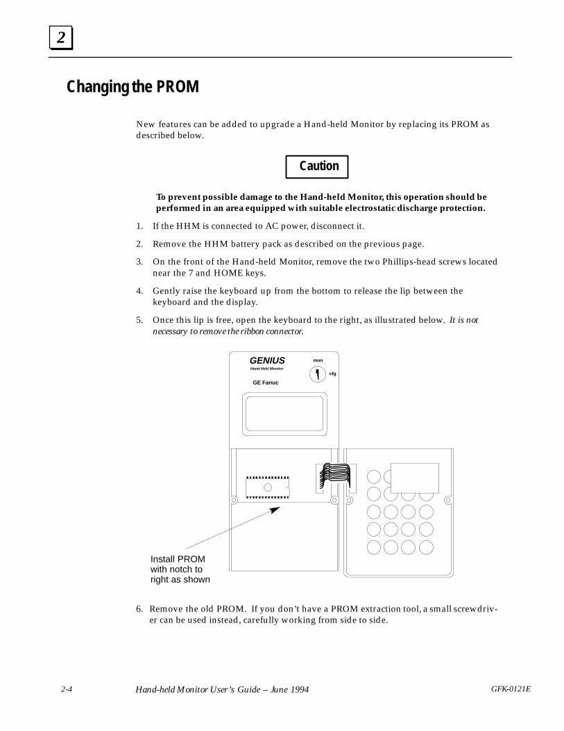
Changing the PROM
New features can be added to upgrade a Hand-held Monitor by replacing its PROM asdescribed below.
Caution
To prevent possible damage to the Hand-held Monitor, this operation should beperformed in an area equipped with suitable electrostatic discharge protection.
1. If the HHM is connected to AC power, disconnect it.
2. Remove the HHM battery pack as described on the previous page.
3. On the front of the Hand-held Monitor, remove the two Phillips-head screws locatednear the 7 and HOME keys.
4. Gently raise the keyboard up from the bottom to release the lip between thekeyboard and the display.
5. Once this lip is free, open the keyboard to the right, as illustrated below. It is notnecessary to remove the ribbon connector.
GENIUS
GE Fanuc
Hand Held Monitor
mon
cfg
Install PROMwith notch toright as shown
6. Remove the old PROM. If you don’t have a PROM extraction tool, a small screwdriv-er can be used instead, carefully working from side to side.

2
2-5GFK-0121E Chapter 2 Hardware Setup
7. If necessary, bend the pins on the PROM so they line up properly with the holes inthe socket. Bend the pins by pressing each side against a clean desk or table top asshown below. If possible, a conductive mat should be used.
Conductive mat
46024
8. Insert the EPROM or Battery-Backed RAM into the socket.
IMPORTANT: Inserting the PROM backward can damage the Micro PLC anddestroy the PROM.
Newer PROMs may be physically longer, but all PROMs must be inserted flush withthe left edge of the socket, with the notch toward the ribbon connector.
9. Reposition the keyboard in its lip and tighten the two screws.
10. Reinstall the battery pack.

2
2-6 Hand-held Monitor User’s Guide – June 1994 GFK-0121E
Permanent Installation
If the Hand-held Monitor is to be installed using the metal bracket provided, follow theinstructions below. Do not install the HHM yet if it will be used to configure I/O blocks.
The mounting bracket provided can be used to install the Hand-held Monitor behind apanel. You will need to make a cutout in the panel for the HHM (see next page).
You will also need to install a connector for the Hand-held Monitor within reach of theHHM’s cable. The extra D-shell connector provided with the Hand-held Monitorrequires a panel cutout, with the bus cable and Hand-held Monitor located on theopposite sides of the panel (see page 2-8).
An optional panel-mountable or DIN rail-mountable connector is also available. It doesnot require a cutout. See page 2-9 for details.
Behind PanelBack of HHM
BracketOptional HHM
Connector
To Power Source
Bus In
Bus Out
Configuring a Permanently-installed HHMOrdinarily, a Hand-held Monitor installed on a panel serves as an operator station. Itsconfiguration may be different from that of a portable HHM.
� Its Device Number must be changed from 0 to some other number.
� Automatic shutoff may be disabled.
� I/O block configuration and other features may also be disabled.
After the HHM is configured, its keyswitch should be placed in MON position, and thekey removed.

2
2-7GFK-0121E Chapter 2 Hardware Setup
HHM Installation Instructions1. Select a suitable location for the HHM. Environmental specifications are listed on
page 1-5. The location must have 115 VAC or 230 VAC power.
2. Cut an opening 3.75� (9.53cm) wide x 8� (20.32cm) high in the panel. Drill fourmounting holes as shown below.
6.00in (15.24cm)
1.00in (2.54cm)
1.00in (2.54cm)
3.75in (9.53cm)
4.38in (11.13cm)
Cutout
3. Attach the bracket to the HHM with the screws, washers, and lockwashers provided.
(4) holes formounting on
panel
(2) holes for mounting toback of Hand-held Monitor
4. Using appropriate hardware (not provided), mount the HHM and bracket in thecutout.
5. Connect the power cord to the HHM, and connect the signal cable to the connector.

2
2-8 Hand-held Monitor User’s Guide – June 1994 GFK-0121E
Installing the D-Shell HHM Connector
Follow the instructions below if you are installing the supplied D-shell connector on thebus.
1. Using the mounting plate as a template, cut an opening in the panel for the matingconnector. Also drill two holes for the mounting hardware.
2. Attach the mounting plate and mating connector to the panel using the mountinghardware supplied.
3. Secure the two ends* of the serial bus cable to the back of the panel using strainrelief brackets.
4. Strip the ends of the wires. Twist the two Serial 1 wires together and attach them topin 5 of the connector. Twist the Serial 2 wires together and attach them to pin 9.Similarly, attach the Shield wire(s)* to pin 4.
The following illustration shows connections for incoming and outgoing serial buscable. As with other devices, the HHM connector may be at either end of its bus. If itis, there will only be one bus cable attached.
MountingHardware
ÎÎÎÎ
ÎÎ ÎÎÎÎÎÎÎÎÎÎÎÎ
ÎÎÎÎÎÎ
Î
ÎÎ
BusCable
Bus Cable
StrainReliefs
Shield(Pin 4)
Mounting Surface(rear view)
MountingPlate
Hand-heldMonitor
Connector
a42240c
SER 2(Pin 9)
SER 1(Pin 5)
Crimp(Qty. 3)
Mating Connector
When making bus connections, the maximum exposed length of bare wires shouldbe two inches. For added protection, each shield drain wire should be insulated withspaghetti tubing to prevent the Shield In and Shield Out wires from touching eachother.
* If the HHM connector is at either end of its bus, it is necessary to install anappropriate terminating resistor across the Serial 1 and Serial 2 wires. The Genius I/OSystem and Communications User’s Manual lists appropriate terminating resistors foreach recommended bus cable type.

2
2-9GFK-0121E Chapter 2 Hardware Setup
Installing a Separate Hand-held Monitor Connector
You can add a connector to the bus for a permanently-mounted Hand-held Monitor, orto provide an additional attachment point for a portable HHM.
The unit shown below (catalog number 44A736310-001-R001) provides a Hand-heldMonitor connector and serial bus terminals.
Hand-held Monitor Connector
Serial Bus Terminals
Panel Mounting Ear2.834 in7.198 cm
1.673 in4.249cm
.5 in1.27 cm
shown at 100% of actual size
X1
X1 X2
X2 SA SB
SA SBX1 Serial 1X2 Serial 2SA Shield InSB Shield Out
46357
Mounting the HHM ConnectorThis unit can be easily mounted on a rail such as a standard 35mm (shown below) or15mm DIN rail. The panel-mounting ears are not used if the unit is installed on a DINrail.
35mm DIN rail
(Removable) DIN railMounting Feet
side view: shown at 50% of actual size
46358
Alternatively, it can be installed directly on a panel using screws through its mountingears. The DIN rail feet on the back of the unit are removed when the unit ispanel-mounted.

2
2-10 Hand-held Monitor User’s Guide – June 1994 GFK-0121E
Making the Bus ConnectionsThe HHM connector has two sets of terminals; one for incoming cable and the other foroutgoing cable.
Connect the Serial 1, Serial 2, and Shield In terminal of either connector to the previousdevice. Connect the Serial 1, Serial 2, and Shield Out terminal of the other connector tothe next device.
When making bus connections, the maximum exposed length of bare wires should betwo inches. For added protection, each shield drain wire should be insulated withspaghetti tubing to prevent the Shield In and Shield Out wires from touching each other.
The following illustration shows connections for incoming and outgoing serial bus cable.As with other devices, the HHM connector may be at either end of its bus. If it is, therewill only be one bus cable attached.
X1
X1 X2
X2 SA SB
SA SB
X1 Serial 1X2 Serial 2SA Shield InSB Shield Out
Bus In
Bus Out
46366
As with other devices, if the HHM Connector is at either end of its bus, install anappropriate terminating resistor across the Serial 1 and Serial 2 terminals. The Genius I/OSystem and Communications User’s Manual lists appropriate terminating resistors for eachrecommended bus cable type.
3
3-1GFK-0121E
Chapter 3 Getting Started
This chapter explains how to:
� Turn on the Hand-Held Monitor
� Set the HHM Baud Rate
� Display the Home Menu
� Change the Hand-held Monitor’s configuration:
� the HHM Device Number
� the HHM Display Language
� the Host CPU
� automatic shutoff
� ability to Change Block ID Parameters
� ability to Change the Baud Rate of Devices on the Bus
� ability to Configure Devices on the Bus
� ability to Force I/O Circuits
� ability to Clear Faults
� Test the operation of the Hand-held Monitor.
� the Keypad
� the Display Screen
� the Internal Electronics
� Display an alphabetical list of definitions for the definitions used on the HHM screen.
3
3-2 GFK-0121EHand-held Monitor User’s Guide – June 1994
Turning on the Hand-Held Monitor
With the battery pack charged, or with the HHMconnected to a suitable AC power source, press theON/Off key to turn the Hand-held Monitor on.
Caution
Do not connect or disconnect theHHM to/from another device or con-nector while it is ON.
Connecting or disconnecting theHHM while it is ON may disruptcommunications on the bus.
Each time you turn on the Hand-held Monitor, itexecutes a brief self-test.
G E N I U S H H M (version)
C O P R . (date)
G E F a n u c N . A .
S E L F T E S T W O R K I N G
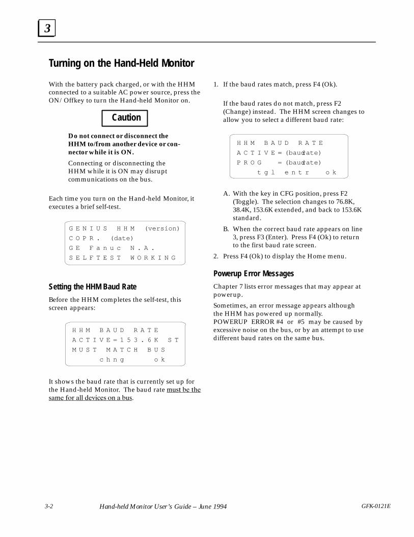
Setting the HHM Baud Rate
Before the HHM completes the self-test, thisscreen appears:
H H M B A U D R A T E
A C T I V E = 1 5 3 . 6 K S T
M U S T M A T C H B U S
c h n g o k
It shows the baud rate that is currently set up forthe Hand-held Monitor. The baud rate ���� �� ���
���� � � � ������ � � ���.
1. If the baud rates match, press F4 (Ok).
If the baud rates do not match, press F2(Change) instead. The HHM screen changes toallow you to select a different baud rate:
H H M B A U D R A T E
A C T I V E = (baud rate)
P R O G =(baud rate)
t g l e n t r o k
A. With the key in CFG position, press F2(Toggle). The selection changes to 76.8K,38.4K, 153.6K extended, and back to 153.6Kstandard.
B. When the correct baud rate appears on line3, press F3 (Enter). Press F4 (Ok) to returnto the first baud rate screen.
2. Press F4 (Ok) to display the Home menu.
Powerup Error Messages
Chapter 7 lists error messages that may appear atpowerup.
Sometimes, an error message appears althoughthe HHM has powered up normally.POWERUP ERROR #4 or #5 may be caused byexcessive noise on the bus, or by an attempt to usedifferent baud rates on the same bus.

3
3-3GFK-0121E Chapter 3 Getting Started
Displaying the Home Menu
This is the Hand-held Monitor’s Home menu:
F 1 : H H M U T I L I T I E S
F 2 : A N A L Y Z E
F 3 : C O N F I G U R A T I O N
F 4 : D E V I C E M E M O R Y
Display the Home menu by either:
A. Pressing F4 (Ok) from the first baud ratescreen, or
B. Pressing the Home key or DMenu key from alower-level screen.
Use the Home menu to get to any other HHMfunction, as shown below.
Notice that different screens appear, depending onthe type of device that is currently communicatingwith the HHM.
F1: HHM CONFIGF2: SELF–TESTF3: HELP
F1: MONITOR BLOCKF2: MNTR/CTRL REFF3: BLOCK/BUS STSF4: PULSE TEST
F3F2F1
The Main HHM Screens
F1
F2
F3
HHM CONFIGBLOCK NO. 0
chng nxt
F1: KEYPAD TESTF2: DISPLAY TESTF3: TEST INTRNALSF4:
F1
F4
F2
F3
REFS O
O O O O O O OA 1 0 0 0 1 1 1
MNTR/CNTL OSTATE: 0NO FAULTS > on off reles
REFS ODC16K 15 v2.0ACTFORCED, NO FAULTSnxt prv actv bus
PULSE TESTREFS 0NO FAULTSexec
F1
F2
F3
PROG BLOCK IDI/OBLOCK NO.ref blk nxt
COPY CONFIGFROM : TO :
chng entr
3 4 5 6 7 8 9 0
(individual featureconfiguration
screens)
(help screens)
See page 3-4 forinstructions.
See page 3-7 forinstructions.
See page 5-4 forinstructions.
See page 5-9 forinstructions.
See page 5-2 forinstructions.
See page 5-17 forinstructions.
See page 4-4 forinstructions.
See Genius I/OBlocks Manual orindividual blockmanual forinstructions.
See page 4-6 forinstructions.
DEVICE MEMORY # (reference)
tgl chng entr SBA
F4
See chapter 6 forinstructions.
F2
F1
F2
F1: GENIUS CONFIGF2: Module Config
F3: Previous Menu
F1 Monitor I/OF2:Faults
F3 Previous Menu
See page 5-15 forinstructions.
See page 4-7 forinstructions.
For Field Control
For Most Genius Devices
F1: HHM UTILITIESF2: ANALYZEF3: CONFIGURATIONF4: DEVICE MEMORY
F1: MONITORF2: CONFIGURATION
F1: PROG BLOCK IDF2: CONFIG BLOCKF3: COPY CONFIG

3
3-4 GFK-0121EHand-held Monitor User’s Guide – June 1994
Configuring the Hand-held Monitor
You can change the following operatingcharacteristics of the Hand-held Monitor:
� PLC reference format.
� 153.6 Kbaud “standard” baud rate.
� Device Number set to 0.
� English language displays.
� Shutdown after 10 minutes of inactivity.
� I/O block configuration enabled.
� I/O circuit forcing enabled.
� Fault clearing enabled.
Select F1 (HHM Utilities) from the Home menu toaccess the HHM Utilities menu:
F 1 : H H M C O N F I G
F 2 : H H M S E L F T E S T
F 3 : H E L P
F 4
To change the configuration of the Hand-heldMonitor, select F1 (HHM Config) from the HHMUtilities menu.
NoteThe HHM key must be in the key-switch, turned to CFG position.
After setting up the configuration, you can preventchanges by turning the keyswitch to the MONposition and removing the key.
Changing the HHM Device Number
The Device Number (serial bus address) assignedto the Hand-held Monitor appears on line 2 of thefirst HHM configuration screen.
H H M C O N F I G
B L O C K N O . O
c h n g n x t
Each device on a Genius bus must have a uniqueserial bus address number. A new HHM hasnumber 0. If multiple HHMs will be used on thesame bus, each of them must be assigned adifferent Device Number.
If you want to change the HHM Device Number,follow these steps:
� Press the ON key. Go to the Home menu. Se-lect F1 (HHM Utilities), then F1 (HHM Config).
� From the HHM Configure menu, press F2(Change) to clear the existing Device Number.Enter the new number and press F3 (Enter).
Pressing F4 from the buad rate screen will advanceyou through additional HHM configurationscreens. Press Home if you want to return to theHome menu, or use the DMenu key to go back tothe previous screen.

3
3-5GFK-0121E Chapter 3 Getting Started
Changing the HHM Display Language
The next display shows the current languageselection.
H H M C O N F I G
L A N G U A G E
E N G L I S H
t g l e n t r n x t
Press F2 (TGL) to change the display language(French, German, Italian, English). Press F3(Enter) to save the change.
Selecting the Host CPU
The next display shows the Hand-held Monitor’shost CPU selection. The choices are: Series Six,Series Five, PCIM/QBIM/GENI, or Series 90.
S E L E C T H O S T C P U
S E R I E S S I X
To change the host CPU type, press the F2 (TGL)key, then press F3 (Enter).
Enabling/Disabling Automatic Shutoff
The next screen shows whether automatic shutoffis selected.
A U T O O F F = 1O m i n
E N A B L E D
This feature conserves battery power by shuttingoff the Hand-held Monitor 10 minutes after thelast key press. To change the current selection,press F2 (Toggle), then F3 (Enter).
Enabling/Disabling the Ability to Change BlockID Parameters
The next display shows whether the Hand-heldMonitor is able to configure the Block Number(serial bus address) of bus devices, as well as theI/O circuit mix of some types of I/O blocks.
C H N G B L K I D
E N A B L E D
This selection also determines whether the HHMis able to assign the Reference Address of I/Oblocks, or change the I/O mapping of a RemoteI/O Scanner (for the modules in its remote drop).
To enable or disable this capability, press F2 (TLG),then F3 (Enter).
3
3-6 GFK-0121EHand-held Monitor User’s Guide – June 1994
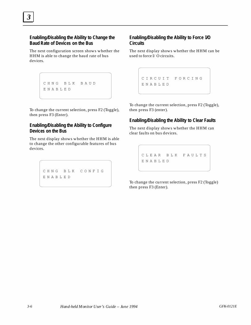
Enabling/Disabling the Ability to Change theBaud Rate of Devices on the Bus
The next configuration screen shows whether theHHM is able to change the baud rate of busdevices.
C H N G B L K B A U D
E N A B L E D
To change the current selection, press F2 (Toggle),then press F3 (Enter).
Enabling/Disabling the Ability to ConfigureDevices on the Bus
The next display shows whether the HHM is ableto change the other configurable features of busdevices.
C H N G B L K C O N F I G
E N A B L E D
Enabling/Disabling the Ability to Force I/OCircuits
The next display shows whether the HHM can beused to force I/O circuits.
C I R C U I T F O R C I N G
E N A B L E D
To change the current selection, press F2 (Toggle),then press F3 (enter).
Enabling/Disabling the Ability to Clear Faults
The next display shows whether the HHM canclear faults on bus devices.
C L E A R B L K F A U L T S
E N A B L E D
To change the current selection, press F2 (Toggle)then press F3 (Enter).

3
3-7GFK-0121E Chapter 3 Getting Started
Testing Operation of the Hand-held Monitor
If you want to test the Hand-held Monitor display,keypad, or internal electronics, select F2 (HHMSELF-TEST) from the HHM Utilities menu. Thismenu of tests appears:
F 1 : K E Y P A D T E S T
F 2 : D I S P L A Y T E S T
F 3 : T E S T I N T R N A L S
F 4 :
Testing the Keypad
Press F1 (KEYPAD TEST). The HHM prompts:
K E Y P A D T E S T
S T R I K E A N Y K E Y
K E Y =
M O N / C F G K E Y = C F G
� Press any key you want to test. Each key pressis shown on the display. The HOME, DMENU, and ON/OFF keys are tested by theiroperation.
� To test keyswitch operation, turn the key andobserve the bottom line of the display.
� Press D MENU to perform another test, orpress HOME to return to the Home menu.
Testing the Display Screen
Press F2 (DISPLAY TEST) from the HHM Utilitiesmenu. The screen first displays uppercase lettersand special characters:
D I S P L A Y T E S T
A B C D E F G H I J K L M N O P
Q R S T U V W Z Y ZO 1 2 3 4 5
6 7 8 9 : > ? – . / 1 O OI
IT
Next, a screen of lowercase letters appears,followed by a continuous test pattern, whichchecks pixel operation. When the test pattern isfinished, press DMENU to perform another HHMtest, or press HOME to return to the Home menu.
Testing the Internal Electronics
Press F3 (TEST INTRNALS) from the Self-Testmenu. After a moment, the HHM displays:
T E S T I N T R N A L S
S E L F T E S T W O R K I N G
e x e c
If an error occurs, one of the following messageswill appear instead.
E : P R O C E S S O R F A I L
E : R A M F A I L U R E
E : E P R O M F A I L U R E
E : E E P R O M F A I L U R E
E : C O M M E R R O R
Press the Clear key and try the test again. If themessage returns, replace the HHM. Otherwise,continue.
An EEPROM failure will not prevent use of theHand-held Monitor. However, the HHM will not beable to retain changes to its default configurationthrough a power cycle.
The COMM ERROR message may indicate thatthe Hand-held Monitor is not attached to acorrectly-terminated bus.

4
4-1GFK-0121E
Chapter 4 Device Configuration Overview
The Hand-held Monitor can be used to configure (establish the operating characteristics for) a widevariety of other devices. Some configurable devices are:
� Genius I/O Blocks, High-speed Counter Blocks, and PowerTRAC Blocks
� the Series 90-70 Remote I/O Scanner and its remote drop
� Field Control stations.
The Hand-held Monitor displays a unique set of configuration screens for each type of configurabledevice.
Because of the wide assortment of configuration features provided by the HHM, it has not been possibleto include them all here. You should refer to the more detailed configuration instructions in the User’sManual for the type of device you are configuring.

4
4-2 GFK-0121EHand-held Monitor User’s Guide – June 1994
Online or Offline ConfigurationDevices can be configured before or afterinstallation on a properly-terminated serial bus. Ifa new device is to be added to an existing busrunning at a baud rate other than 153.6 Kbaudstandard, the device must first be configuredoffline. Be careful adding new devices to existingsystems. Be sure the baud rate configured for thenew device matches that of the system - never mixbaud rates on a bus.
Online Configuration
When configuring a device on an operating bus,the Hand-held Monitor must be the ONLY HHMplugged into a device on the bus. If devices areconfigured online, the HHM automatically checkfor PLC reference address conflicts.
Offline Configuration
It may be most convenient to configure devicesoff-line at a central location. Each device will needto be connected to an appropriate source of powerand to earth ground. To prepare a device foroff-line configuration:
1. Connect a 75 ohm resistor across the Serial 1and Serial 2 terminals, or use the 75 ohmterminator plug (IC660BLM508).
2. Attach a grounding strap to the device’sground screw. Be sure that the strap isconnected to earth ground.
a42468
AttachGroundStrap
ÎÎÎÎÎÎÎÎÎÎÎÎÎÎÎÎÎÎÎÎ
TerminatorPlug
1234H
N
3. Wire the device to the power source and applypower.
Warnings
If the device is not properly grounded,hazardous voltages may exist. Death orinjury may result.
DO NOT TOUCH the connectors orwiring after powering up the device.Hazardous voltages exist, and death orinjury may result.
Starting ConfigurationNote: To assign a serial bus address, theHand-held Monitor must be directly attached tothe device being configured. Additional featurescan be configured with the Hand-held Monitorconnected at any point on the bus. In that case, thedevice being configured must be selected as theactive device (on the Block/Bus Status screen).
1. Begin with the Hand-held Monitor turned off.Attach the HHM to the device (see below) orto another bus connection point.
ÎÎÎÎÎ
a42307ÎÎÎÎÎÎÎÎÎÎÎÎÎÎ
ÎÎÎÎÎÎÎÎÎÎÎÎÎÎÎÎÎÎÎÎÎÎÎÎÎ
ÎÎÎÎÎÎÎÎÎÎÎÎÎÎÎÎÎÎÎÎÎÎÎ
2. Turn the Hand-held Monitor on. After theHHM completes its powerup sequence, theHome menu appears. The Hand-heldMonitor’s Change Block Configuration optionmust be enabled to complete the instructionsin this section. For a new device, the HHM’sChange Block ID and Change Block Baudoptions must also be enabled.
4
4-3GFK-0121E Chapter 4 Device Configuration: Overview
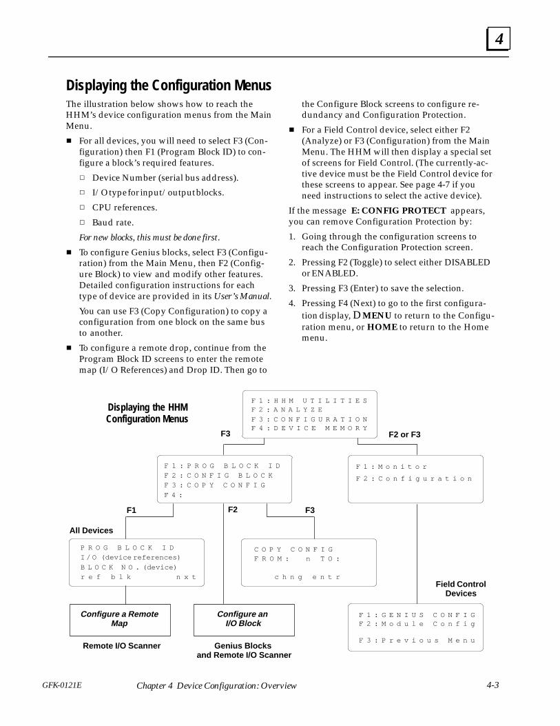
Displaying the Configuration MenusThe illustration below shows how to reach theHHM’s device configuration menus from the MainMenu.
� For all devices, you will need to select F3 (Con-figuration) then F1 (Program Block ID) to con-figure a block’s required features.
� Device Number (serial bus address).
� I/O type for input/output blocks.
� CPU references.
� Baud rate.
For new blocks, this must be done first.
� To configure Genius blocks, select F3 (Configu-ration) from the Main Menu, then F2 (Config-ure Block) to view and modify other features.Detailed configuration instructions for eachtype of device are provided in its User’s Manual.
You can use F3 (Copy Configuration) to copy aconfiguration from one block on the same busto another.
� To configure a remote drop, continue from theProgram Block ID screens to enter the remotemap (I/O References) and Drop ID. Then go to
the Configure Block screens to configure re-dundancy and Configuration Protection.
� For a Field Control device, select either F2(Analyze) or F3 (Configuration) from the MainMenu. The HHM will then display a special setof screens for Field Control. (The currently-ac-tive device must be the Field Control device forthese screens to appear. See page 4-7 if youneed instructions to select the active device).
If the message E: CONFIG PROTECT appears,you can remove Configuration Protection by:
1. Going through the configuration screens toreach the Configuration Protection screen.
2. Pressing F2 (Toggle) to select either DISABLEDor ENABLED.
3. Pressing F3 (Enter) to save the selection.
4. Pressing F4 (Next) to go to the first configura-tion display, D MENU to return to the Configu-ration menu, or HOME to return to the Homemenu.
Genius Blocks and Remote I/O Scanner
Configure an I/O Block
F1 F2 F3
F 1 : H H M U T I L I T I E SF 2 : A N A L Y Z E
F 4 : D E V I C E M E M O R YF 3 : C O N F I G U R A T I O N
F 1 : P R O G B L O C K I D
F 2 : C O N F I G B L O C K
F 3 : C O P Y C O N F I G
F 4 :
P R O G B L O C K I D
I / O (device references)
B L O C K N O . (device)
r e f b l k n x t
C O P Y C O N F I GF R O M : n T O :
c h n g e n t r
F 1 : M o n i t o r
F 2 : C o n f i g u r a t i o n
Field ControlDevices
F 1 : G E N I U S C O N F I GF 2 : M o d u l e C o n f i g
F 3 : P r e v i o u s M e n u
All Devices
F3 F2 or F3
Remote I/O Scanner
Configure a RemoteMap
Displaying the HHMConfiguration Menus

4
4-4 GFK-0121EHand-held Monitor User’s Guide – June 1994
Completing the Program Block ID Screens
Select F1 (Program Block ID) from theConfiguration menu to complete the mandatorypart of a device’s configuration. (The HHM’sCHNG BLK ID capability must be enabled).
When the HHM is set up for a PLC host, theProgram Block ID screen looks like this:
P R O G B L O C K I D
I / O (device references)
B L O C K N O . (device #)
r e f b l k n x t
If there are ? symbols on the screen, thereference address and/or Device Number have notyet been configured. If there are * symbols on thescreen, a reference address was previouslyassigned, but is out of range for the host CPUcurrently set up for the HHM. If this happens,check the host CPU setup in the HHM Utilities.
When the HHM is set up for a PCIM/QBIM/GENIhost, references are not used. Instead, the secondline describes the device:
P R O G B L O C K I D
I S O L 8 (device #)
B L O C K N O . (device #)
r e f b l k n x t
To Enter or Change the Device Number: theHand-held Monitor must be connected directly tothe device.
1. Press F2 (blk). Then, enter the intended num-ber (1-30). If you make a mistake, press F2twice again, then enter the correct number.
2. Press the F3 (Enter) key. If the device is on-lineand the number has already been used, an er-ror message appears.
To Complete the Program Block ID Screen: TheProgram Block ID screen is used to configureadditional features for some devices. These varyfrom device to device; you should refer to thedevice’s User’s Manual if you need moreinformation.
To Change the Device’s Baud Rate: press F4(Next) from the Program Block ID screen. (TheHHM’s CHNG BLK BAUD capability must beenabled).
S E L E C T B A U D R A T E
A C T I V E = 1 5 3 . 6 K S T
P R O G = 1 5 3 . 6 K S T
t g l e n t r n x t
The bus will not operate unless all devices are set for thesame baud rate. Check the baud rate beforeintroducing blocks onto an operating bus.
� To change the device’s baud rate, press F2(Toggle), then press F3 (Enter).
� Cycle power to all devices on the bus at thesame time to use the new baud rate.
To Set the I/O Map for a Remote I/O Scanner:The next screen is used to assign data types andlengths for a Series 90-70 Remote I/O Scanner. Seethe next page.

4
4-5GFK-0121E Chapter 4 Device Configuration: Overview
Configuring a Remote I/O ScannerAfter selecting the baud rate, the next ProgramBlock ID screen is used to assign data types andlengths for a Series 90-70 Remote I/O Scanner.
P R O G R E M O T E M A P
% I
L E N G T H ( P T S )
t g l r e f s e n d n x t
Configuration Notes
The Remote I/O Scanner User’s Manual explainsremote drop configuration in detail. You shoulduse it as a reference during remote dropconfiguration.
Also, look over the information below. Especially,note that it is not always possible or desirable touse a HHM for remote drop configuration.
� If the remote drop includes any Analog Expan-der Modules, Logicmaster 90 must be used forconfiguration; do not use a HHM.
� When a remote drop is configured with aHHM, all I/O modules will operate in defaultmode; module options can only be configured withthe Logicmaster 90-70 software.
� Unless the Remote I/O Scanner is configurationprotected, pressing F3 (send) from the RemoteMap configuration screen causes the HHM toautomatically configure the remote drop. Thisconfiguration will REPLACE any existing I/Oconfiguration (including one entered using Lo-gicmaster 90-70), and return I/O module op-tions to their original defaults.
� Remote drops configured with Logicmaster90-70 are automatically protected. Please checkcarefully before removing configuration protec-tion with a Hand-held Monitor.
� The Hand-held Monitor automatically creates aconfiguration for a nine-slot rack, regardless ofthe actual rack size. If the remote drop has afive-slot rack, the HHM will later assume thatthere are unfilled slots. If this is a problem, Lo-gicmaster 90-70 can be used for configuration,or to edit an automatic configuration done witha Hand-held Monitor. Then, the configurationcan be stored to the Remote I/O Scanner.
Configuring the Remote Drop
To configure the remote drop with the HHM:
1. Enter a starting address and length for: %I (dis-crete inputs), %Q (discrete outputs), %AI (ana-log inputs), %AQ (analog outputs) on thescreen shown at left. The data lengths mustnot add up to more than 128 bytes of inputsand 128 bytes or outputs. If they do, an errormessage will appear when you attempt to sendthe data to the Remote I/O Scanner.
2. Next, press F2 (drop) and enter a Remote DropID (between 16 and 254).
P R O G R E M O T E M A P
D R O P I D _____________
t g l d r p s e n d n x t
3. Press the F3 (send) key to download theseselections to the Remote I/O Scanner.
Note: Do not perform this step if you want topreserve a configuration entered using the Lo-gicmaster software.
The HHM configures the I/O references of Se-ries 90-70 I/O modules (only) in the remotedrop. It assigns references in ascending order,starting with the slot next to the Remote I/OScanner. The leftmost module of each type (%I,%Q, %AI, or %AQ) in the rack receives the firstavailable reference of the appropriate type.
4. Press F4 (nxt) to go to the Program Block IDscreen.
5. After completing these screens, press F2 (Con-figure Block) to complete the Genius configura-tion screens, or to display information aboutthe I/O modules in the remote drop.
The module description screens that appearduring the configuration sequence are read-only; boards cannot be configured here.
Go through these block description screens toconfigure:
� BSM Present
� BSM Controller
� CPU Redundancy
� Configuration Protection

4
4-6 GFK-0121EHand-held Monitor User’s Guide – June 1994
Configuring Genius BlocksTo configure individual features of a Genius block,the block must be the “active” device.
Selecting the Active Device
1. From the Analyze menu, select F3 (Block/BusStatus).
2. Press F1 (Next) or F2 (Previous), to reach thedevice’s description screen.
3. When the desired device appears, press F3 (Ac-tive) to make it the active device. (On a dualbus, the HHM must be on the same bus as theactive block. If it is not, either move the HHMor force the bus selection as described onpage 5-3).
4. Press D MENU twice to return to the MainMenu.
Configuring Block Features
Select F3 (Configuration), then F2 (Config Block).For Genius blocks, the HHM shows the firstconfiguration display. For example:
P U L S E T E S T OI
R E F S (block references)
E N A B L E D
t g l e n t r n x t
The HHM shows the feature to be configured (inthe example above, it is the Pulse Test option). Italso shows the current status of that feature.
When the Hand-held Monitor is set up for a PLChost, line 2 shows the references assigned to thedevice being configured. If there are ? symbols onthe screen, the device’s reference address has notyet been configured. If there are * symbols on thescreen, a reference address was previouslyassigned, but it is out of range for the host CPUcurrently set up for the Hand-held Monitor. If thishappens, check the host CPU setup in the HHMUtilities.
When the HHM is set up for a PCIM/QBIM/GENIhost, line 2 shows the device type and DeviceNumber (serial bus address) instead.
Because there are so many different deviceconfiguration screens, it is not possible to show
them all here. You should refer to the User’sManual for the device you are configuring fordescriptions of its configuration screens anddetailed instructions for completing them.
Configuration Instructions
1. To advance through the HHM configurationdisplays making changes as needed, use the F4(Nxt)key. You can pass through feature dis-plays without making entries.
2. To change a feature, use the TGL and CHNGkeys to select choices or enter other values. Onscreens used to enter individual I/O circuit op-tions, use the F1 ( > ) key to choose a circuit,then select the option using the TGL or CHNGkey. On some displays, you can enter new val-ues from the keypad.
3. Press the F3 (Enter) key to save each change.
Copying a Configuration
If there are similar devices on an operating bus,you can use the Copy Configuration feature tocopy the configuration from one to the another.Both of the devices must have a Device Numberalready configured, and they must be operating atthe same baud rate. The device to be copied TOmust not be Configuration Protected.
The device to be copied FROM must be the activedevice (move the HHM to that block or select itfrom the Block/Bus Status screen).
1. To begin, press F3 (Copy Configuration) fromthe Configuration menu. The HHM shows:
C O P Y C O N F I G
F R O M : n T O :
c h n g e n t r
2. The Device Number of the active device ap-pears next to the word FROM. Enter the De-vice Number of the device being copied TO.Press F3 (Enter).
3. Press the F4 (Execute) key. The configuration iscopied.

4
4-7GFK-0121E Chapter 4 Device Configuration: Overview
Configuring Field Control Station
1. From the HHM Main Menu, display the specialset of menus for Field Control.
A. If the Bus Interface Unit or Field Processor isthe current-selected device, press F2 (ana-lyze) twice or F3 then F2.
B. If it is NOT the currently-selected device:
� Select F2 (analyze) then F3 (Block/BusStatus).
� Press the F1 (nxt) or F2 (prev) key repeat-edly to reach the serial bus address of theBIU or Field Processor. Press F3 to make itthe active device. Then, press ∆Menu, fol-lowed by F2 (Monitor/Control Ref).
F 1 : M o n i t o r
F 2 : C o n f i g u r a t i o n
From this menu, press F2 (Configuration). Thismenu appears:
F 1 : G E N I U S C O N F I G
F 2 : M o d u l e C o n f i g
F 3 : P r e v i o u s M e n u
� Press F1 to configure the BIU/Field Processor.
� Press F2 to configure individual modules.
Change the Bus Address
When you press F1 (Genius Configuration) fromthe Configuration menu, the HHM shows theserial bus address previously configured for theBIU or Field Processor:
D e v i c e S B A1 4
P r v > e n t r
If the bus address is correct, press F2 to go on.
Note: If a BIU or Field Processor has a Serial BusAddress conflict on an operating bus, it will notscan the modules in the station until the fault iscleared.
1. If you want to change the address, enter thenew address using the keypad.
2. Press F4 (entr). An error message appears ifthe number has been used for another device.
Select a PLC Reference Address
If the host is not a Series Six PLC or Series FivePLC, no entry is necessary here.
If the host is a Series Six PLC or Series Five PLC,assign an I/O or register reference address.
shows reference type
S t a t T b l A d d r
< > I O 6 e n t r
O O O O O
1. Use the F3 key to toggle the selection of SeriesSix I/O memory, Series Five I/O memory, orregister memory. (See the BIU/Field ProcessorUser’s Manual for information about memoryusage in the Series Five and Series Six PLC).
If I/O memory is used, the amount required isequal to the number of bits of discrete dataPLUS analog data. Each analog reference usedconsumes 16 points.
If register memory is used, an amount is re-quired that is equal to the total number of bytesof input data PLUS all of the output data
2. Key in the number of the block’s beginning I/Oor register reference. This may be:
Series Six I/O 1 to 993Series Five I/O 1 to 2041Registers 1 to 16383
3. Press the F4 (Entr) key.
Configure Additional Features
On the screens that follow, select these features:
� Fault Reporting� Genius bus redundancy� BSM Controller� Output default time (for redundancy)� CPU redundancy� Duplex redundancy: default mode for outputs� Configuration protection

4
4-8 GFK-0121EHand-held Monitor User’s Guide – June 1994
Configuring Individual Field Control ModulesGo to the Field Control configuration menu:
F 1 : G E N I U S C O N F I GF 2 : M o d u l e C o n f i g
F 2 : P r e v i o u s M e n u
From this menu, press F2 to configure theindividual modules in the station.
Disable the I/O Scan
While you configure the modules in the station,you may want to disable I/O scanning. (The BusInterface Unit or Field Processor begins scanningI/O as soon as it is powered up).
I O S c a n D I S A B L E D *
P r v > t g l e n t r
When the I/O scan is disabled, previouslyunconfigured module inputs and outputs defaultto 0. For previously-configured modules, inputsand outputs either default or hold their last stateor value, as configured.
1. If you want to change the present selection,press F3 (tgl).
2. Press F4 (entr). If you want to go to the nextscreen without changing the selection, press F2( > ).
Configure Data Addresses and Lengths
The next screens are used to assign the startingaddresses and lengths for I, then Q, then AI, thenAQ data.
If the host is a Series 90 PLC, these shouldcorrespond to the memory assignments made forthe BIU or Field Processor during PLC configuration.
If the host is a Series Six or Series Five PLC, onlythe length selected here is used; the entry madeon the starting address screen is not used by thePLC. For those PLC types, the starting address wasassigned on an earlier screen.
1. For each data type, enter a starting address fordiscrete input data (I). For example:
< > e n t r
B l k M a p S t a r t 1
I O O O O1
2. Press F4 to accept the value. Then, enter alength in bits for I data. For example:
B l k M a p L n g t h 6 4
< > e n t r
3. Press F4 (entr) to accept the value.
4. Continue as above, entering starting addressesand lengths for the other data types.
The lengths entered must not add up to morethan 128 bytes of inputs (discrete + analog)and 128 bytes of outputs (discrete + analog).
5. Press F1 ( > ) after entering the length for AQdata (the fourth data type).
If you changed any starting address or lengthentries, the HHM displays this screen:
M a p h a s c h a n g e dA c c e p t ?
n o y e s
6. To accept the changes and continue to the nextmenu, press F4 (yes).

4
4-9GFK-0121E Chapter 4 Device Configuration: Overview
Add Modules and Assign References
The first module configuration screen looks like this:
Slotnumber
Racknumber
Use F1 and F2 to displayanother slot (module)
< > t g l r e a d
R O : S 1 E M P T Y
The Rack Number is always 0.
The Slot Number refers to the location of themodule relative to the BIU or Field Processor.
Read a Module Identification
If there is a module in the currently-selected slot,pressing F4 (read) from the “empty slot” screenbrings up the module identification screen:
D i s c r e t e O u t 1 6Moduletype
t g l e n t r
R O : S 1 M o d t y p e ?
� If you want to change the module type dis-played, press F3 (tgl) to list other module types.
� To accept the module type, press F4 (entr).
Select a Module Type
If a module is not present in the selected slot, pressF3 (tgl) to select Generic I/O or Special I/O. Thenpress F4 (entr).
G e n e r i c I / O
t g l e n t r
R O : S 1 I / O t y p e ?
� Use the F3 (tgl) key again to go through themodule names.
� When the correct module name appears, pressF4 (entr).
Assign I/O References for the Module
After you “accept” a module into the slot, a screenlike this appears:
I_
e n t r
R O : S 1 I 1 6
Specify the I/O references to be used by themodule. For most applications, you can simplyhave the BIU/Field Processor assign the nextavailable references in that memory type.
A. To assign the next available references, justpress F4 (entr).
B. If you want to assign specific references, enterthe starting address. Press F4 (entr).
Module references are automatically assigned bythe BIU or Field Processor based on its configureddata addresses and the number of pointsappropriate for the module type.
Editing a Module Configuration
To edit the module’s configuration, press F4 (zoom).Refer to the module configuration instructions in theBIU/Field Processor User’s Manual.
Delete an Existing Module Configuration
To delete the configuration of the module in thepresent slot, press F3 (delete) then F4 (enter). Notethat this removes the entire module configuration.
Configuring Module Features
Configure additional module features as described inthe BIU/Field Processor User’s Manual. For example:
� Change the module’s reference address.
� Module Fault Reporting (discrete)
� Default inputs (or outputs) or Hold Last State(discrete and analog)
� Channel Fault Reporting (analog)
� Channel Active (analog)
� Input Current/Voltage Ranges (analog)
� Input or output scaling (analog)
� Alarm thresholds (analog)
� Output default values (analog)
5
5-1GFK-0121E
Chapter 5 Monitoring the Bus and its Devices
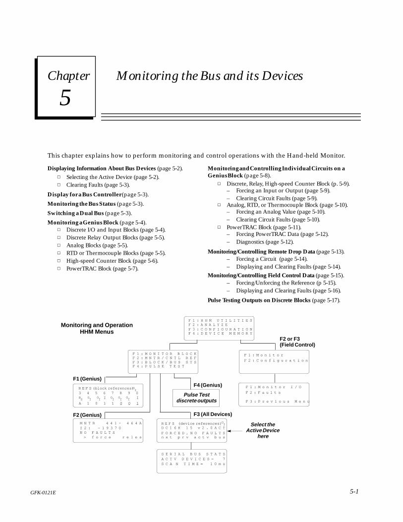
This chapter explains how to perform monitoring and control operations with the Hand-held Monitor.
Displaying Information About Bus Devices (page 5-2).� Selecting the Active Device (page 5-2).� Clearing Faults (page 5-3).
Display for a Bus Controller (page 5-3).
Monitoring the Bus Status (page 5-3).
Switching a Dual Bus (page 5-3).
Monitoring a Genius Block (page 5-4).� Discrete I/O and Input Blocks (page 5-4).� Discrete Relay Output Blocks (page 5-5).� Analog Blocks (page 5-5).� RTD or Thermocouple Blocks (page 5-5).� High-speed Counter Block (page 5-6).� PowerTRAC Block (page 5-7).
Monitoring and Controlling Individual Circuits on aGenius Block (page 5-8).
� Discrete, Relay, High-speed Counter Block (p. 5-9).– Forcing an Input or Output (page 5-9).– Clearing Circuit Faults (page 5-9).
� Analog, RTD, or Thermocouple Block (page 5-10).– Forcing an Analog Value (page 5-10).– Clearing Circuit Faults (page 5-10).
� PowerTRAC Block (page 5-11).– Forcing PowerTRAC Data (page 5-12).– Diagnostics (page 5-12).
Monitoring/Controlling Remote Drop Data (page 5-13).– Forcing a Circuit (page 5-14).– Displaying and Clearing Faults (page 5-14).
Monitoring/Controlling Field Control Data (page 5-15).– Forcing/Unforcing the Reference (p 5-15).– Displaying and Clearing Faults (page 5-16).
Pulse Testing Outputs on Discrete Blocks (page 5-17).
F1 (Genius)
F2 (Genius) F3 (All Devices)
F 1 : H H M U T I L I T I E SF 2 : A N A L Y Z E
F 4 : D E V I C E M E M O R YF 3 : C O N F I G U R A T I O N
F 1 : M o n i t o r
F 2 : C o n f i g u r a t i o n
F 1 : M o n i t o r I / O
F 2 : F a u l t s
F 3 : P r e v i o u s M e n u
F2 or F3(Field Control)
F 1 : M O N I T O R B L O C KF 2 : M N T R / C N T L R E FF 3 : B L O C K / B U S S T SF 4 : P U L S E T E S T
R E F S (block references) 3 4 5 6 7 8 9 0 I I
OI
OI
OI
BS
OI
OI
OI
M N T R 4 4 1 – 4 6 4 AI 2 : – 1 9 3 7 0N O F A U L T S > f o r c e r e l e s
R E F S (device references) D C 1 6 K 1 5 v 2 . 0 A C T
F O R C E D , N O F A U L T Sn x t p r v a c t v b u s
OI
S E R I A L B U S S T A T SA C T V D E V I C E S = 7S C A N T I M E = 1 0 m s
F4 (Genius)
Pulse Testdiscrete outputs
Select theActive Device
here
Monitoring and OperationHHM Menus
A 1 0 1 1 0 0 1

5
5-2 GFK-0121EHand-held Monitor User’s Guide – June 1994
Displaying Information About Bus Devices
Select F3 (Block/Bus Status) from the Analyzemenu to:
� Display the references assigned to any device.
� Display the revision level of any device.
� Display the description and Global Data ad-dress of a bus controller.
� Display the fault status of a Genius block orRemote I/O Scanner (remote drop).
� Select the active device.
� Clear all faults on the active device.
� Access the Bus Status display.
This screen provides a quick way to check for faultsand forced circuits before starting up a system.
Block/Bus Status Displays for Bus Devices
Example displays are shown below. (Display formatfor bus controllers is shown on the next page).
Genius Block (discrete)
Remote I/O Scanner
BIU/Field Processor
R E F S (devicereferences) OI
D C 1 6 K 1 5 v 2 . O A C T
F O R C E D , N O F A U L T S
n x t p r v a c t v b u s
R E F S * _ * G
R I O 1 5 v 3 . 5 A C T
N O F O R C E , F A U L T S
n x t p r v a c t v b u s
R E F S * _ * OI
f l d p r 2 O v 1 . O A C T
N O F O R C E
n x t p r v a c t v b u s
Line 1 shows the I/O references used by the device.If * symbols appear instead of references, thedevice’s references are incorrect for the type of hostCPU currently set up for the HHM. For example, ifa device is assigned to Series Six registers, and theHHM is set up for a Series 90 host, the HHM willdisplay * symbols instead of references.
Line 1 also provides information about the devicecurrently being displayed:
I = Input block
O = Output blockOI = Block with both inputs and outputs
A = Analog, RTD or Thermocouple block
G = PowerTRAC block or Remote I/O Scanner
Line 2 identifies the device and shows its serial busaddress (also called its Device Number or blocknumber), and its revision level.
Line 3 shows whether the device presently hasany forces or faults. If the device is a Field ControlBIU or Field Processor, however, the presence offaults is not indicated on this screen.
Selecting Another Device
Press F1 (Next) or F2 (Previous) as needed todisplay information about other device.
Note: Poor bus conditions may cause the HHM toskip (not display) a device that is present on thebus. Try moving the HHM to a differentconnector on the bus. Occasionally, this problem iscaused by certain older Genius blocks that do notcommunicate with the HHM properly. If theproblem persists, such blocks can be upgraded.
Selecting the Active Device
Initially, the active device is the one to which theHHM is connected.
You can display information about other deviceswithout making them “active”.
However, for many functions the HHM must beattached to another device or the other device mustbe made “active” by following the steps below.
1. From the Analyze menu, select F3 (Block/BusStatus).
2. Press F1 (Next) or F2 (Previous), to reach thedevice’s description screen.
3. When the device’s screen appears, press F3(Active) to make it the active device. (On adual bus, the HHM must be on the same bus asthe active block. If it is not, either move theHHM or force the bus selection)
4. Press D MENU to return to the Analyze menu.

5
5-3GFK-0121E Chapter 5 Monitoring the Bus and its Devices
Clearing Faults from the Block/Bus Status Screen
Pressing the CLEAR key from this screen clears ���faults on the active device. For Genius blocks, ifyou want to clear a specific circuit fault, select F2(Monitor/Control Reference) from the Analyzemenu instead.
Block/Bus Status Display for a Bus Controller
If the active device is a bus controller, the Block/BusStatus display shows information appropriate to thatbus controller type. For example:
S E R I E S 6B U S A D R : (device #)(vers)R E G (registers)n x t p r v r / g b u s
The first line identifies the bus controller type. If itis a Series Five bus controller, PCIM, or QBIM, thefirst line indicates:
G E N I
The second line of the display shows the buscontroller’s Device Number followed by itsfirmware revision level.
Reading a Global Data Address
The third line of a bus controller’s Block/Bus Statusscreen shows its assigned Global Data address.
If no Global Data address appears, it means thateither:
� The bus controller has no Global Data address.
� A Series 90-70 bus controller has a Global Dataaddress in %I, %Q, %AI, %AQ, or %R memory,and no optional Series Six register address wasconfigured for the bus controller.
If a Global Data address has been set up, you canuse the F3 (R/G) key to toggle between (R)egisterand (G)lobal memory format. If no Global Datareference has been set up, the F3 key is not assigned.
Monitoring the Bus Status
To display the number of devices currently operatingon the bus, and the current bus scan time, select F4(Bus) from the Block/Bus Status display.
S C A N T I M E 1O m s
S E R I A L B U S S T A T S
A C T V D E V I C E S = 7
The bus scan time shown is rounded down to thenearest millisecond (10mS represents 10.01 to10.99mS).
Switching a Dual Bus
To force a bus switch in a redundant bus system,the HHM must be connected to the same bus asthe presently-active device.
1. If necessary, make the BSM Controller the ac-tive device.
A. From the Analyze menu, select F3 (Block/Bus Status).
B. Press F1 (Next) or F2 (Previous), to reach thestatus screen for the BSM Controller.
C. When it appears, press F3 (Active) to makethe BSM Controller the active device.
2. Press D MENU to return to the Analyze menu.
3. From the Analyze menu, select F2 (Monitor/Control Reference). The HHM shows the ac-tive bus and whether it is forced. For example:
M N T R / C T R L (input ref)S T A T E : B U S B F R C
> b u s A b i s B r e l s
4. Press F2 or F3 to select the other bus. The LEDon the BSM is off when bus A is selected andon when bus B is selected. The I/O EnabledLED on each block on the active bus blinks.

5
5-4 GFK-0121EHand-held Monitor User’s Guide – June 1994
Monitoring a Genius Block
Select F2 (Monitor Block) from the Analyze menu to:
� Display the I/O type of all circuits on the activeblock.
� Display (not change) forces on the active block.
� Display the bus presently selected by the BSMController.
Making the Block Active
If the block is not presently selected as the “active”block, follow the steps below.
1. From the Analyze menu, select F3 (Block/BusStatus).
2. Press F1 (Next) or F2 (Previous), to reach thedevice’s description screen.
3. When the block’s screen appears, press F3 (Ac-tive) to make it the active device. (On a dualbus, the HHM must be on the same bus as theactive block. If it is not, either move the HHMor force the bus selection)
4. Press D MENU to return to the Analyze menu.
After selecting the active device, use F1 (MonitorBlock) to monitor its data. This is a exampledisplay for a discrete I/O block:
R E F S (block references) OI
BS
OI
OI I O
IOI
OI I
A 1 O 1 1 O O 1
3 4 5 6 7 8 9 O
Monitor Block screens for other types of Geniusblocks are described below.
Block References
On all the Monitor Block screens for a Geniusblocks, line 1 shows the block references. If *symbols appear instead, the references are out ofrange for the CPU host currently setup for theHand-held Monitor. For example, if a block isassigned to Series Six registers, and the HHM is setup for a Series 90 host, the HHM displays*symbols instead of references.
If the HHM is set up for PCIM mode, referencesare not used; a device description appears instead.
Monitor Block Display for Discrete I/Oand Input Blocks For a discrete block, the Monitor Block displayshows the I/O type and current state of eachcircuit. This is an example display for an 8-circuitgrouped I/O block:
R E F S (block references) OI
BS
OI
OI I O
IOI
OI I
A 1 O 1 1 O O 1
3 4 5 6 7 8 9 O
Line 1 indicates the block’s I/O type:
I = InputO = OutputOI = Combination (I/O)
Line 2 shows the last digit of each circuit’sreference address. The abbreviation on line 3describes the I/O type of each circuit:
I = InputIT = Tri–State inputO = OutputOI = Output with feedback
Bs = Circuit that controls a BSM
Line 4 shows the current state of each circuit. Thisinformation is updated continuously as the I/Ostates change.
An underline means a circuit is forced (and doesnot reflect actual circuit status):
O = OFFO = forced OFF1 = ON1 = forced ON
If the circuit is configured as a BSM controller, theselected bus is displayed on line 4. If forced, theactive bus letter is underscored.
A = bus AA = forced to bus AB = bus BB = forced to bus B
Displaying Additional Circuits for a 32-circuit DCblock: Press a key from F1 to F4 to toggle thedisplay between circuits 1 to 16 and circuits 17 to 32.

5
5-5GFK-0121E Chapter 5 Monitoring the Bus and its Devices
Monitor Block Display for Discrete RelayOutput Blocks
For a Relay block, the Monitor Block screen showsthe current open (O) or closed (C) states of allrelay outputs:
R E F S (blockreferences)O1 2 3 4 5 6 7 8 9 O 1 2 3 4 5 6O O O O O O O O O O O O O O O OO O O O C CO O O O O C O O C C
Line 2 shows the last digit of each circuit’sreference address. The ‘O‘s on line 3 show thateach circuit is an output. Line 4 shows each relayoutput’s present state. An underline means therelay is forced.
O = openO = forced openC = closedC = forced closed
Monitor Block Display for Analog Blocks
For an analog block, each Monitor Block screenshows the current value of two circuits at a time.This is an example display:
R E F S (circuit references) A
I 1 : 1 8 3 5 7
I 2 : 2 9 O 6 1 F R C
>
Line 1 indicates that the block is an (A)nalog block.Lines 2 and 3 display the current values of twocircuits. On an analog block, each circuit mayreport either unconverted analog data, or datathat has been scaled to be suitable for theapplication.
The abbreviation FRC means a value is forced.
Press F1 ( > ) to display the next pair of circuits.
Monitor Block Display for RTD orThermocouple Blocks
For an RTD or Thermocouple Input block, theMonitor Block screen shows the current values oftwo inputs at a time. Values reported by the blockmay be tenths of degrees (Celsius or Fahrenheit),tenths of ohms, or unconverted counts. This is anexample display showing tenths of degreesCelsius:
R E F S (circuit references) A
I 1 : 1 5 O . O C
I 2 : 2 5 . 5 C
Line 1 indicates that the block is an (A)nalog block.Lines 2 and 3 display the input values. Theabbreviation FRC means a value is forced.
Press F1 ( > ) to display the next pair of inputs.

5
5-6 GFK-0121EHand-held Monitor User’s Guide – June 1994
Monitor Block Display for a High-speed Counter Block
For a High-speed Counter block, the MonitorBlock function displays a sequence of screens withthe following information:
1. The states of the block’s four Preset Outputs.
2. The states of the block’s Control Inputs.
3. The current values of the block’s internal datastorage registers: Accumulator, Counts perTimebase, and Strobe.
The exact appearance and sequence of screensdepends upon whether the block has been set upfor four-counter (Type A), two-counter (Type B), orone-counter (Type C) operation. The letter a, b, orc on the top line of the screen shows how theblock is set up.
Preset Outputs
First, the Preset Outputs are displayed:
R E F (ctrnumber) (ctr type)
P R E S E T O U T P U T
1 2 3 4
O O O O
Outputs that are forced are shown with anunderscore (forced outputs do NOT respond tothe actual value of the counter).
Control Inputs
Press F1 ( > ) to display the block’s Control Inputs:
C O N T R O L I N P U T S c
1 1 1 2 1 2 3
D H P P S S S
1 1 1 1 1 1 O
On this screen, the numbers on line 2 identify thefirst, second, third, of fourth control input of thesame input type on the block. The third lineidentifies the input type: Disable Input (D), HomeInput (H), Preload Input(P), or Strobe Input (S).The screen’s bottom line shows the current state ofeach Control Input.
Register Values
Press F1 ( > ) to display the current value in eachcounter ’s accumulator, Counts-per-Timebaseregister, and Strobe register(s):
R E F (number) (counter type)
A C C 1 : _ + (acc.value)
C T B 1 : _ + (countvalue)
> n x t
Use the F1 ( > ) key to display the strobe value(s),and additional values appropriate to the countertype. For more detailed instructions for using aHand-held Monitor with a High-speed Counter,refer to the High-speed Counter User’s Manual.

5
5-7GFK-0121E Chapter 5 Monitoring the Bus and its Devices
Monitor Block Display for a PowerTRAC Block
If the active device is a PowerTRAC block, theHHM’s Monitor Block function displays thefollowing screens:
� One screen showing the states of all of theblock’s Status Inputs.
� Individual screens showing the block’s currentcalculated data values. In the Monitor Blockfunction, these values are NOT labelled. It iseasier to display this information using theMonitor/Control Reference function (F2), be-cause those displays are labelled.
� One screen showing the states of all of theblock’s Control Outputs.
On each of these screens, you can press F1 ( > ) todisplay next screen, or press F2 (ref) and enter areference location to display a specific screen. Fora sequential list of the PowerTRAC block data, seepage 5-11.
Status Inputs
The Monitor Block function first displays thePowerTRAC block’s Status Inputs:
R E F (inputreferences) I
1 2 3 4 5 6 7 8 9 O 1 2 3 4 5 6
O O O1 1 O O O O O O1 O O O O
> r e f
Line 2 indicates each of the 16 possible bitlocations for status data. Lin e3 shows the currentstates of all inputs.
Bits 1 – 3 indicate the status of table data transfer,for datagram communications.
Bit 4 = 1 indicates the block has captured an over-current event.
Bit 5 should always be 1, indicating that the block’sphase-lock loop is synchronized with theincoming AC voltage.
Bit 12 = 1 means the overcurrent event indicatedby bit 4 occurred on phase A.
Bit 13 = 1 means the overcurrent event indicatedby bit 4 occurred on phase B.
Bit 14 = 1 means the overcurrent event indicatedby bit 4 occurred on phase C.
Bit 15 = 1 means the overcurrent event indicatedby bit 4 occurred on the auxiliary currentline.
Bit 16 = 1 indicates an internal calculation has re-sulted in an out-of-range value. The blockshould be reconfigured to prevent this.
Calculated Data
After the Status Inputs, the HHM displays theblock’s calculated data. If the PowerTRAC Block isversion 2.3 or later, this includes the additional“low-priority I/O” data listed on page 5-11.
R E F (input reference) I
1 1 7
> r e f
Control Outputs
After the calculated data screens, the HHM’sMonitor Block function displays the PowerTRACblock’s Control Outputs. You can also display thisdata by using the F2 (ref) key to select output 1.You may need to toggle (F2) the memory type.
R E F (outputreferences) O
1 2 3 4 5 6 7 8 9 O 1 2 3 4 5 6
O O O O O O O O O O O O O O O O
> r e f
Line 2 indicates each of the 16 possible bitlocations for Control Outputs. Line 3 shows thecurrent state of each Control Outputs. Theseoutputs are communications handshaking bits,sent from the CPU to the block for certaindatagram communications. Information aboutthese outputs is in the PowerTRAC Block User’sManual.

5
5-8 GFK-0121EHand-held Monitor User’s Guide – June 1994
Monitoring and Controlling Individual Circuits on a Genius Block
Select F3 (Monitor/Control Reference) from theAnalyze menu to:
� Display the present state or value of any circuiton the active block.
� Display the diagnostics status of any circuit.� Force and unforce individual circuits.� Force a bus switch on a dual bus.� Clear individual circuit faults.
Making the Block Active
The block whose circuits will be monitored orcontrolled must first be made “active” by followingthe steps below.
1. From the Analyze menu, select F3 (Block/BusStatus).
2. Press F1 (Next) or F2 (Previous), to reach thedevice’s description screen.
3. When the block’s screen appears, press F3 (Ac-tive) to make it the active device. (On a dualbus, the HHM must be on the same bus as theactive block. If it is not, either move the HHMor force the bus selection)
4. Press D MENU to return to the Analyze menu.
From the Analyze menu, press F2.
Basic Monitor/Control Display Format
Each Monitor/Control Reference screen providesinformation about one circuit, channel, or datavalue. For example:
M N T R 4 4 1 – 4 6 4 A
I 2 : – 1 9 3 7
N O F A U L T S
> f o r c e r e l e s
O
Line 1 shows the references used by that circuit. Ifthese are out of range for the host CPU set up forthe Hand-held Monitor, line 1 instead shows:
M N T R (circuit number) + * A
For example, the first circuit on the block appearsas: 1 + *
If the HHM is set up for PCIM mode, referencesare not used; a block description appears instead.

5
5-9GFK-0121E Chapter 5 Monitoring the Bus and its Devices
Monitor/Control Reference Display for a Discrete, Relay, or High-speed Counter Block
For a discrete, Relay, or High-speed Counter block,the Monitor/Control Reference screen looks likethis:
M N T R / C N T L (reference) I
S T A T E :
N O F A U L T S
> o n o f f r e l e s
O
Line 1 identifies the circuit currently beingmonitored. Pressing F1 ( > ) displays othercircuits.
Line 2 shows the state of the circuit. In theexample above, the circuit is OFF and not forced(no underline). Status is obtained directly fromthe block for both inputs and outputs. If thecircuit is an output and no–load sensing isenabled it reflects the current flow out of the I/Oblock to the load, as well as voltage at the fieldterminals; otherwise, it indicates only the voltageat the field terminals (output from the switch).
Forcing an Input or Output
(The Hand-held Monitor’s circuit forcingcapability must be enabled to force or unforce acircuit). To force a circuit on, press F2 (ON). Toforce it off,press F3 (OFF). The force remains untilchanged by the HHM (even through loss of blockpower). To clear a force, press F4 (reles).
Diagnostics
Line 3 of the Monitor/Control Reference screenshows whether the circuit has any faults. If itdoes, one of the following diagnostic messagesappears:
Failed switch: The commanded state of the circuitdoes not match the actual state of theswitch or load.
Loss of I/O power: One pair of circuits on an dis-crete isolated block is not receiving power.
No load: The load is drawing less than the block’sminimum current level.
Open wire: An open wire condition has been de-tected on a tristate input.
Overload: The output exceeds the block’s steadystate current limit.
Overtemperature: The block’s internal tempera-ture exceeds 100�C.
Short circuit: Transient current above the block’sshort circuit limit.
Clearing Circuit Faults
After correcting a fault condition, press the CLEARkey to remove the message and restore thereference to normal operation (the Clear BlockFaults function must be enabled to use thisfeature). If the fault condition still exists, the faultmessage will reappear.

5
5-10 GFK-0121EHand-held Monitor User’s Guide – June 1994
Monitor/Control Reference Display for an Analog, RTD, or Thermocouple Block
For an analog, RTD, or Thermocouple block, theMonitor/Control Reference screen shows thecurrent value for each circuit. For example:
M N T R (ckt. reference) A
I 2 : – 1 9 3 7
N O F A U L T S
> f o r c e r e l e s
O
For an analog block, the values may representeither engineering units or unscaled analog data.
For an RTD or Thermocouple block, the valuesrepresent tenths of degrees (Celsius orFahrenheit), tenths of ohms, or unconvertedcounts.
Press F1 ( > ) to display other circuits.
Forcing an Analog, RTD, or ThermocoupleValue The HHM’s circuit forcing capability must beenabled to perform this function.
1. Press F2 (Force) to force the displayed circuit.
2. If you make a mistake entering a value, use theClear key to delete one digit at a time, startingwith the last. To exit without forcing a circuit,press F2 (Change).
3. Press F3 (Enter) to save this value as the valuefor the circuit. The forced value will remainuntil you press F4 (reles), or enter a new value.
Diagnostics
Line 3 shows whether the circuit has any faults. Ifit does, one of these messages appears on line 3:
Feedback error: There is a wiring error or otherhardware fault on a Current-source Ana-log block. The output’s actual current dif-fers from the commanded current bymore than 250mA.
High alarm/low alarm: An analog input value ex-ceeds its high or low alarm limit.
Input shorted: An RTD input circuit measurementis less than expected for the RTD type.
Internal fault: Internal calibration readings for apair of RTD circuits are out of tolerance.
Open wire: On an RTD block, the RTD is missingor faulty, or there is an open wire. On ananalog block, an input configured for 4 to20mA has less than 2mA present.
Overrange/underrange: An analog or RTD circuitexceeds its maximum value.
Overtemperature: The block’s internal tempera-ture exceeds 100�C.
Wiring error: There is a faulty connection be-tween an RTD and the block.
Clearing Circuit Faults
After correcting a fault condition, press the CLEARkey to remove the message and restore thereference to normal operation (the Clear BlockFaults function must be enabled to use thisfeature). If the fault condition still exists, the faultmessage will reappear.

5
5-11GFK-0121E Chapter 5 Monitoring the Bus and its Devices
Monitor/Control Reference Displays for a PowerTRAC Block For a PowerTRAC block, the Monitor/ControlReference function displays:
� 16 screens, each showing the state of one StatusInput. This information is more easily dis-played with the Monitor Block function,whichshows all 16 Status Inputs on one screen. Seepage 5-7.
� Individual labelled displays of the block’s currentcalculated data values. For PowerTRAC blockversion 2.3 or later, this includes the “low-priorityI/O”screens described on the next page.
� 16 screens, each showing the state of one of theblock’s Control Outputs. Control outputs arealso more easily displayed using Monitor Block.
PowerTRAC Data Sequence
The following table shows the sequence ofPowerTRAC block data that can be displayed onthe Monitor/Control Reference screens:
InputWord
1 Status inputs (16 screens in Monitor/Control Reference)
23456789
1011la
ted
Dat
a
Voltage phase A to BVoltage phase B to CVoltage phase C to AVoltage A to N (Line–to–neutral PTs only)Voltage B to N (Line–to–neutral PTs only)Voltage C to N (Line–to–neutral PTs only)Current phase ACurrent phase BCurrent phase CAuxiliary CT current
10111213141516171819
Cal
cula
ted Current phase C
Auxiliary CT currentActive power phase AActive power phase BActive power phase CReactive power AReactive power BReactive power CTotal power factorAccumulated power
202122232425262728293031
32–64
Low
–Pri
orit
y I/
O D
ata Fundamental VARs phase A
Fundamental VARs phase BFundamental VARs phase CFundamental Power Factor, totalHarmonic VARS as % of V–A, phase AHarmonic VARS as % of V–A, phase BHarmonic VARS as % of V–A, phase CHarmonic VARS as % of V–A, totalLine FrequencyTemperature Alarm StatusExtended Watt-hour accumulator (upper 5 digits)Extended Watt-hour accumulator (lower 3 digits)not used
OutputWord 1
Control outputs (16 screens in Monitor/Control Reference)
For explanations of the data provided by aPowerTRAC block, see the PowerTRAC Block User’sManual.
Selecting a Memory Type or Address
To select a specific data item, you can enter itsmemory type and/or address. Press F2 (ref). Thisscreen appears:
M N T R __
t g l c h n g e n t r
1. Enter the reference number and press F3 (entr).If the HHM is set up for a PLC host, I/O refer-ences increment by 16 and word(register) refer-ences increment by 1. For a PLC host, both I/Oand word references start at the first referenceassigned to the block. If the HHM is set up fora PCIM/QBIM/GENI host, references begin at 1and increment by 1.
2. The memory type blinks on the screen. Tochange the memory type, use the F2 (tgl) key.
3. Press F3 (entr) to display the information.

5
5-12 GFK-0121EHand-held Monitor User’s Guide – June 1994
PowerTRAC Status Inputs Screens
First, the Hand-held Monitor displays 16 screensshowing the states of Status Inputs:
M N T R / C N T L (references) O
S T A T U S I N P U T S
S T S
> r e f f o r c e d i a g
O
To display additional data, press the F1 ( > ) key.
PowerTRAC Calculated Data Screens
After the Status Inputs, the HHM displays theblock’s calculated data values. Lines 2 and 3identify the data being displayed and show itspresent value. In the example below, voltage A toN is 117 volts.
M N T R (input references) 1
V a n
S T S 1 1 7
> r e f f o r c e d i a g
PowerTRAC Extra Calculated Data (LPIO)Screens
If the PowerTRAC block is version 2.3 or later, theHand-held Monitor next shows a series of screenswith extra calculated (“Low-Priority I/O”) data.The block may or may not automatically providethis data to the host, depending on the block’srevision level and configuration. A CPU can usedatagrams to read the data.
L P I O # 1 W 2 O I
F U N D . V A R a
S T S – 2 7 O> r e f d i a g
On these screens, the top line shows the serial busaddress of the block and the relative data wordbeing displayed. For example, the screen aboveshows the 20th input word (Fundamental VARsfor phase A). This area of line 1 blinks as areminder that the numbers shown are notreference addresses.
PowerTRAC Control Outputs Screens
Finally, the HHM displays 16 screens showing thestates of individual Control Outputs (datagramhandshaking bits). If you use the F1 ( > ) key toreach the Control Outputs, notice that there areseveral unused references following the ExtraCalculated Data data. You can use F2 (ref) to godirectly to output 1. You may need to toggle thememory type to %Q (or O, depending on the hostCPU setup of the HHM).
M N T R / C N T L (reference) O
C O N T R O L O U T P U T S
S T S
> r e f f o r c e d i a g
O
Forcing PowerTRAC Data
(The HHM’s circuit forcing capability must beenabled to perform this function). Display thedata you want to force. Press F3 (force).
For bit data, the HHM displays:
m o n o n o f f r e l e s
Press F2 (on) or F3 (off). To release the force, pressF3 (reles).
For word data, the HHM displays:
S T S 4
f o r c e r e l e a s e
Press F2 (force). The screen next displays:
F O R C E T O :
c h n g e n t r
Press F2 (chng). Enter the force value, then pressF3 (entr). To release the force, press F4 (release).
Diagnostics
The PowerTRAC block does not report circuitfaults. If you use the F4 (diag) key from theMonitor/Control Reference screen, the messageNO FAULTS will appear.

5
5-13GFK-0121E Chapter 5 Monitoring the Bus and its Devices
Monitoring/Controlling Remote Drop Data
The HHM can display diagnostics and current I/Ostates, and force and unforce individual I/O pointson I/O modules in a remote drop.
When the active device is a Remote I/O Scanner,the HHM’s Monitor Block and Monitor/ControlReference functions display the same set ofscreens. This is unlike HHM operation for Geniusblocks, where the screens for Monitor Block andMonitor/Control Reference are different.
For the Remote I/O Scanner, the monitoringscreens provide the following information:
1. The states of the discrete inputs in the remotedrop, in ascending order.
2. The values of the analog inputs in the remotedrop, in ascending order.
3. The states of the discrete outputs for the re-mote drop, in ascending order.
4. The values of the analog outputs for the re-mote drop, in ascending order.
On each screen, line 3 shows the state or value ofone circuit at a time. It also indicates whether thecircuit is forced, or has a fault as illustrated below.The first screen that appears is the Monitor screenfor the module with the first %I reference.
M N T R 1
1 4 3 # O . 2 % I 1
S T S O F A U L T
> r e f f o r c e d i a g
Line 1 shows the relative number in the word ofthe circuit being monitored:
M N T R 1
Here, it is the first circuit on the block. The secondline identifies the I/O module being monitored:
1 4 3 # 4 . 2 % I 1
It shows the Remote Drop ID (143 in thisexample), the rack number (0),the slot number (2),and the memory type (%I). The number on therighthand side of the second line represents a dataword.
1 4 3 # 4 . 2 % I 1
Starting reference(groups of 16)
Rack Number
Remote ID Number
Slot Number
Reference Type
The Series 90-70 I/O reference for the circuit is oneless than the sum of the two numbers on therighthand side of the HHM screen. For example:
M N T R 3
1 4 3 # 4 . 3 % I 3 3
3 + 33 – 1=35
In this example, the circuit being monitored is%I0035.
Displaying Other Circuits
To display additional circuits, press the F1 ( > ) key.The HHM will step through each available circuit.To jump directly to a particular device, memorytype, or address, press F2 (ref). This screenappears, to enter the desired information.
M N T R 3
t g l c h n g e n t r
1. Enter the reference number. Press F3 (entr).The memory type blinks on the screen.
2. If you want to select a different reference type(for example, to display%AQ instead of %I),press F2 (chng) to toggle the memory type.
3. With the desired information displayed, pressF3 (entr) to monitor the circuit.

5
5-14 GFK-0121EHand-held Monitor User’s Guide – June 1994
Forcing a Circuit
(The HHM’s circuit forcing capability must beenabled to perform this function). Display thecircuit you want to force. Press F3 (force).
For a discrete circuit, the HHM displays:
m o n o n o f f r e l e s
Press F2 (on) or F3 (off) to force the circuit. Theforced state appears on line 3. To release the force,press F3 (reles).
For an analog circuit, the HHM displays:
S T S 4
f o r c e r e l e a s e
Press F2 (force) to force the circuit. The screennext displays:
F O R C E T O :
Press F2 (chng). Enter the force value, then pressF3 (entr). The forced value will appear on line 3.
F R C 1
> r e f f o r c e d i a g
To release the force, press F4 (release) from theforce/release screen.
Displaying and Clearing Remote Drop Faults
To display diagnostics for a circuit, press F4 (diag)from the Monitor screen. If there is a fault, itappears on line 3. For example:
D I A G 3
1 4 3 # O . 3 % I 3 3
O V E R C U R R E N T
m o n n x t
If there is no fault on the circuit you aremonitoring, the Hand-held Monitor searches theRemote I/O Scanner’s internal fault table to seewhether there are any faults on the remote drop.If there are any uncleared faults on the remotedrop, the HHM displays the fault that occurredfirst (the oldest fault). For example:
D I A G 3
1 4 3 # O . 2 % A I 1
U N D E R R A N G E
m o n n x t
The HHM identifies the location where the faultoccurred (on line 2). From this screen, you candisplay additional faults on the remote drop bypressing F4 (nxt). Faults will appear in the samesequence in which they occurred. For example,if thefourth oldest is being shown, pressing F4 (nxt)displays the fifth oldest, and so on.
To return to the Monitor screen you started from,press F1 (mon).
Clearing Faults
After correcting fault–causing conditions, you canreturn to the Block/Bus Status menu to clear allfault messages for the remote drop. (The ClearBlock Faults function must be enabled to use thisfeature).

5
5-15GFK-0121E Chapter 5 Monitoring the Bus and its Devices
Monitoring/Controlling Field Control Data
The HHM can display diagnostics and current I/Ostates, and force and unforce individual I/O pointson Field Control modules.
1. From the HHM Main Menu, display the FieldControl main menu.
F 1 : M o n i t o rF 2 : C o n f i g u r a t i o n
A. If the BIU or Field Processor is the active de-vice, press either F3 (Configuration) or F2(analyze) twice.
B. If it is NOT the active device select F2 (ana-lyze) then F3 (Block/Bus Status).
� Press the F1 (nxt) or F2 (prev) key re-peatedly to reach the serial bus addressof the BIU/Field Processor. Press F3 tomake it the active device.
� Then, press ∆Menu, followed by F2(Monitor/Control Ref).
2. Press F1 (Monitor). This menu appears:
F 1 : M o n i t o r I / OF 2 : F a u l t s
F 3 : P r e v i o u s M e n u
3. Select F1 (monitor I/O) to display the Monitorscreen for the first %I reference.
Referencebeing
monitoredCurrent
state or value
Indicates force is in effect
< > f r c h e x
I O O O O1 * O B
Changing the Reference Type Being Displayed
Use the F1 ( < ) key to select a reference type: I(discrete inputs), Q (discrete outputs), AQ (analogoutputs), or AI (analog inputs).
Displaying Another Reference
Use the F2 ( > ) key to advance through the pointreference screens for the selected reference type.
Changing the Display Mode
The letter in the upper right corner of the displayshows the present data type:
B binaryH hexD decimal
Use the F4 (mode) key if you want to change thedisplay data type.
Returning to the Previous Menu
Press the HHM Clear key when you want toreturn to the main Field Control menu.
Forcing/Unforcing the Displayed Reference
I/O points can be forced and unforced from theHand-held Monitor (the HHM’s circuit forcingcapability must be enabled to use this function).Forcing an I/O point changes its state in the FieldProcessor’s EEPROM memory. If the circuit is anoutput, the physical state of the output alsochanges. If the circuit is an input, the forced inputdata is sent to the CPU. A circuit retains its forcedstate or value if power is removed. The forcedcircuit ignores data from an attached input device,or output data from the CPU. The force canONLY be removed from the Hand-held Monitor.
1. If the display is set to hex (H) or binary (B),change it to decimal (D) by pressing F4.
2. Press the F3 (force) key to force the referencenow being displayed.
f r c u n f r c
I O O O O1 * 1 D
3. Press F3 (force) again. Then, enter the forcedstate or value. The HHM displays an asterisk toindicate the state of value now shown is forced.See the illustration at left.
4. Use the F4 (unforce) key from the same screenwhen you want to unforce the point.

5
5-16 GFK-0121EHand-held Monitor User’s Guide – June 1994
Displaying Field Control Faults
A Hand-held Monitor can display faults from aBus Interface Unit or Field Processor whileattached anywhere on the Genius bus.
1. From the HHM Main Menu, display the FieldControl main menu (instructions are on theprevious page).
F 1 : M o n i t o rF 2 : C o n f i g u r a t i o n
2. From this menu, select F1 (Monitor). The fol-lowing menu appears:
F 1 : M o n i t o r I / OF 2 : F a u l t s
F 3 : P r e v i o u s M e n u
3. Select F2 (faults) to display fault informationfor the Field Processor and its modules.
The Faults menu appears:
F 1 F i r s t 1 6 F l t s
F 2 L a s t 1 6 F l t s
F 3 P r e v i o u s M e n u
4. Press F1 to display the first set of 16 faults (onefault at a time). For example:
S l o t # 1 F a u l t # 1
E X T R A I / O M O D U L E
< > e x i t
A. Use F1 and F2 to display another fault
B. If there are no faults, the HHM displays themessage: No Faults on the top line.
5. To display the last 16 faults (if any):
A. Press F4 (exit) to return to the screen shownat the top if this page.
B. Press F2 (last 16 faults).
Clearing Field Control Faults
If faults are present, pressing the HHM Clear keyhere has no effect. To clear faults from theHand-held Monitor you need to do the following:
1. Return to the HHM Main Menu.
2. Press F2 (Analyze).
3. Press F3 (Block./Bus Status).
4. Make the BIU or Field Processor the active de-vice if it is not.
5. Press the Clear key.
Clearing faults from the Hand-held Monitor doesnot clear faults at the host PLC. To keep the entiresystem in step and up-to-date, fault clearingshould be performed from the host PLC.

5
5-17GFK-0121E Chapter 5 Monitoring the Bus and its Devices
Pulse Testing Outputs on Discrete Genius Blocks
Pulse Testing verifies the ability of outputs on adiscrete block to change state. Pulse Testing alsoindicates whether output circuits (wires, powersources, loads) will start or stop current flow.Pulse testing is recommended for blockscontrolling outputs that seldom change state. Itprovides assurance that when needed, an outputwill operate correctly. Blocks that control outputswhich frequently change state do not need to usethe Pulse Test feature. Pulse Testing does notprovide enough energy to activate mechanicaldevices such as motor starters, relays, or solenoidvalves, but it may change the state of a very smallload.
Executing a Pulse Test
(To execute a Pulse Test, the Hand-held Monitor’sPULSE TEST capability must be enabled). Theblock being Pulse Tested must be the active block.
1. From the Analyze menu, press F4 (Pulse Test).The Pulse Test display appears:
P U L S E T E S T
R E F S (ckt references)
N O F A U L T S
e x e c
OI
For a PLC host, line 2 shows the block’s as-signed references and its I/O configuration.Line 3 shows whether the block has any faults.
2. Press F1 (Execute) to pulse all outputs on theblock once. If the word FAULTS appears, itmeans that one or more diagnostic errors haveoccurred. Go to the Monitor/Control menu todisplay the specific type of fault that has oc-curred.
Clearing Pulse Test Faults
If you press the CLEAR key from the Pulse Testscreen, all faults on the block will be cleared.
If you press the Clear key from theMonitor/Control screen (after displaying a specificcircuit fault), only that fault will be cleared.
Pulse Test Error Messages
If the Pulse Test cannot be performed or if theblock fails to respond, an error message appears.Press the Clear key to remove the message.
E : P U L T S T D I S A B L E
A Pulse Test cannot be performed unless theblock’s configuration is changed.
E : I N V L D B L K T Y P E
The block does not support Pulse Tests.
E : I N V L D B L K C O N F I G
The active block is an inputs–only block.
E : P U L S E T E S T F A I L
The HHM has not received an acknowledgementfrom the block within the predetermined amountof time. Retry the test. If it continues to fail, checkthe serial bus cable and active block.

6
6-1GFK-0121E
Chapter 6 Reading CPU Memory
This chapter explains how to use a Hand-held Monitor to read data in a specified memory location in aSeries 90–70, Series Six, or Series Five PLC. New data from the specified memory location is displayedevery three seconds.
General Instructions _________________________________________
1. Be sure the Hand-held Monitor is set up for the type of PLC host you want to read data from. (Seepage 3-5 for instructions).
2. If the Hand-held Monitor is NOT attached directly to the PLC’s bus controller, or if another device isdesignated as “active” when you enter the Device Memory function, use the F4 (SBA) key and enterthe bus controller’s Device Number (serial bus address).
3. To read data from the selected bus controller, press F4 from the Main Menu and specify the memorylocation to be read as instructed below.
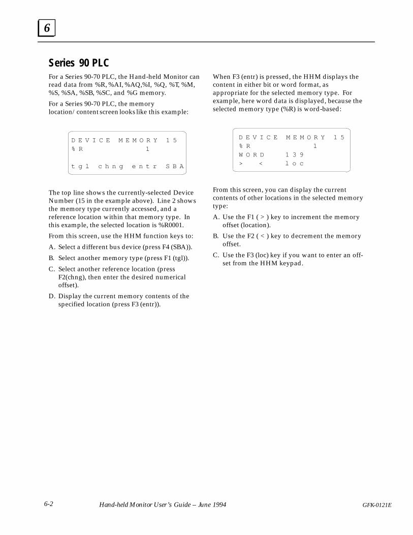
6
6-2 GFK-0121EHand-held Monitor User’s Guide – June 1994
Series 90 PLC For a Series 90-70 PLC, the Hand-held Monitor canread data from %R, %AI, %AQ,%I, %Q, %T, %M,%S, %SA, %SB, %SC, and %G memory.
For a Series 90-70 PLC, the memorylocation/content screen looks like this example:
D E V I C E M E M O R Y 1 5% R 1
t g l c h n g e n t r S B A
The top line shows the currently-selected DeviceNumber (15 in the example above). Line 2 showsthe memory type currently accessed, and areference location within that memory type. Inthis example, the selected location is %R0001.
From this screen, use the HHM function keys to:
A. Select a different bus device (press F4 (SBA)).
B. Select another memory type (press F1 (tgl)).
C. Select another reference location (pressF2(chng), then enter the desired numericaloffset).
D. Display the current memory contents of thespecified location (press F3 (entr)).
When F3 (entr) is pressed, the HHM displays thecontent in either bit or word format, asappropriate for the selected memory type. Forexample, here word data is displayed, because theselected memory type (%R) is word-based:
D E V I C E M E M O R Y 1 5% R 1W O R D 1 3 9> < l o c
From this screen, you can display the currentcontents of other locations in the selected memorytype:
A. Use the F1 ( > ) key to increment the memoryoffset (location).
B. Use the F2 ( < ) key to decrement the memoryoffset.
C. Use the F3 (loc) key if you want to enter an off-set from the HHM keypad.

6
6-3GFK-0121E Chapter 6 Reading CPU Memory
Series Six PLC For a Series Six PLC, the Hand-held Monitor canread data from register memory. That includes I/Odata mapped into register memory, (it is easier todisplay I/O data with the HHM’s Monitor Block orMonitor Control Reference function).
For a Series Six PLC, the Device Memory screenlooks like this example:
D E V I C E M E M O R Y 7
M E M : (location)
t g l c h n g e n t r S B A
The top line shows the currently-selected DeviceNumber (7 in the example above). If there is acurrently-selected memory location, it appears onthe second line of the display as two numbersseparated by a colon.
The number on the left will be:
32768 for a Series Six PLC
The number on the right is the actual memorylocation that will be read.
From this screen, use the Hand-held Monitorfunction keys to:
A. Select a different device on the bus (press F4(SBA)).
B. Select another memory type (press F2 (chng)).See right for instructions.
C. Select another reference location in the dis-played memory type (press F2(chng)). Seeright for instructions.
D. Display the current memory contents of thespecified location (press F3 (entr)).
Enter or Change the PLC Type
To enter or change the PLC type:
1. Press F3 (chng). A cursor appears at the left ofthe colon. For a Series Six PLC, enter the num-ber 32768.
2. Press the F3 (entr) key.
Enter or Change the Memory Location
To enter or change the memory location:
1. On the same screen, press F1 ( > ) to move thecursor to the right of the colon.
2. Press F2 (chng).
3. Enter a number equal to the actual registernumber plus 16383. For example, for regis-ter#100, you would enter (16383 + 100), whichis 16483:
M E M : 3 2 7 6 8 : 1 6 4 8 3
Expanded I/O Data
Expanded I/O data is mapped into registers andcan be accessed as described above. I/O data fromchannel 0, or the main I/O chain in an expandedI/O system can be displayed using the integerresult of the following formula:
((point number – 1) / 8) + table offset
The table offset is either 8192 for the output tableor 8320 for the input table. Example: to displayinput 672, you would enter: ((672 – 1) / 8) +8320,which is 8403.

6
6-4 GFK-0121EHand-held Monitor User’s Guide – June 1994
Series Five PLCFor a Series Five PLC, the Hand-held Monitor canread data from register memory. That includes I/Odata mapped into register memory, (it is easier todisplay I/O data with the HHM’s Monitor Block orMonitor Control Reference function).
For a Series Five PLC, the Device Memory screenlooks like this example:
D E V I C E M E M O R Y 7
M E M : (location)
t g l c h n g e n t r S B A
The top line shows the currently-selected DeviceNumber (7 in the example above). If there is acurrently-selected memory location, it appears onthe second line of the display as two numbersseparated by a colon.
The number on the left will be:
133 for a Series Five PLC
The number on the right is the actual memorylocation that will be read.
From this screen, use the Hand-held Monitorfunction keys to:
A. Select a different device on the bus (press F4(SBA)).
B. Select another memory type (press F2 (chng)).See right for instructions.
C. Select another reference location in the dis-played memory type (press F2(chng)). Seeright for instructions.
D. Display the current memory contents of thespecified location (press F3 (entr)).
Enter or Change the PLC Type
To enter or change the PLC type:
1. Press F3 (chng). A cursor appears at the left ofthe colon. For a Series Six PLC, enter the num-ber 32768.
2. Press the F3 (entr) key.
Enter or Change the Memory Location
To enter or change the memory location:
1. On the same screen, press F1 ( > ) to move thecursor to the right of the colon.
2. Press F2 (chng).
3. Enter the byte offset of the data. This is equalto (2 x register #) – 2. For example, for regis-ter#100, you would enter (2 x 100) – 2, whichis 198.
I/O Data
Series Five I/O data can be displayed using theinteger result of this formula:
(point number) / 8 + table offset
The table offsets for Series Five I/O are:
channel 1 inputs 32768channel 2 inputs 32896channel 1 outputs 33024channel 2 outputs 33152
Example: to display channel 2 output 12, youwould enter:12/8 + 33152, which is 33153:
M E M : 1 3 3 : 3 3 1 5 3
Press F3 (ENTR) to save the memory location. Todisplay the memory content of this location, pressF3 (ENTR) again.
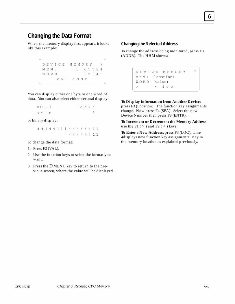
6
6-5GFK-0121E Chapter 6 Reading CPU Memory
Changing the Data FormatWhen the memory display first appears, it lookslike this example:
D E V I C E M E M O R Y 7M E M : 1 : 6 5 5 2 4W O R D 1 2 3 4 5 v a l a d d r
You can display either one byte or one word ofdata. You can also select either decimal display:
W O R D 1 2 3 4 5
B Y T E 3
or binary display:
4 4 1 4 4 1 1 1 4 4 4 4 4 4 1 1
4 4 4 4 4 4 1 1
To change the data format:
1. Press F2 (VAL).
2. Use the function keys to select the format youwant.
3. Press the D MENU key to return to the pre-vious screen, where the value will be displayed.
Changing the Selected Address
To change the address being monitored, press F3(ADDR). The HHM shows:
D E V I C E M E M O R Y 7M E M : (location)W O R D (value)> < l o c
To Display Information from Another Device:press F3 (Location). The function key assignmentschange. Now press F4 (SBA). Select the newDevice Number then press F3 (ENTR).
To Increment or Decrement the Memory Address:use the F1 ( > ) and F2 ( < ) keys.
To Enter a New Address: press F3 (LOC). Line4displays new function key assignments. Key inthe memory location as explained previously.

7
7-1GFK-0121E
Chapter 7 Error Messages
This chapter explains error messages that may be displayed on the Hand-held Monitor.
Powerup Error MessagesIf an error occurs during the Hand-held Monitor’sself-test, this multi-language error display mayappear:
P W R U P E R R O R # 1
E R R E U R # 1
E I G T E S T : F E H L # 1
E R R O R E I N I Z # 1
Cycle power to the Hand-held Monitor and tryagain. If the message returns, look for its errornumber in the list at right.
#2 The HHM has a faulty EPROM. Obtain areplacement or an HHM upgrade kit.
#4 The HHM may have been assigned a De-vice Number already used on the bus. Pressthe ON/OFF key, then disconnect the HHMfrom the device it is attached to. Press theON/OFF key again. Following the instruc-tions on page 3-4, assign the HHM a differ-ent Device Number.At 38.4 Kbaud, unterminated HHM cablemay cause this message. Remove the HHMcable or check that HHM is connected to aproperly-terminated bus.This error may occur if the Hand-held Mon-itor is connected to a bus and an incorrectbaud rate is selected.
#5 This number indicates an internal fault, orexcessive noise on the bus, or that the bus isoperating at a different baud rate from theHHM. Press the ON/OFF key then discon-nect the HHM cable from the bus ��� fromthe HHM. Press the ON/OFF key again. Ifthe message reappears, replace the HHM.This error may occur if the Hand-held Mon-itor is connected to a bus and an incorrectbaud rate is selected.
#1, 2, 3, or 6 indicates that the Hand-held Monitormust be replaced.

7
7-2 GFK-0121EHand-held Monitor User’s Guide – June 1994
Operating Error MessagesThe HHM may display one of the messagesshown below when the ON/OFF key is pressed orduring operation. If a message appears, press theClear key, then follow any action suggested.
E : N O A C T I V E A D D R
No active device has been selected, so manyfunctions do not operate. See page 5-2 to select anactive device.
E : K E Y = M O N T R O N L Y
Place the keyswitch in Configure mode (the keymust be present). Press Clear, then retry theoperation. Press Enter.
E : F N C T N D I S A B L E D
The function just selected is disabled by theHHM’s current configuration. Press the Clear keyto remove the message.
E : C O M M E R R O R
HHM cannot communicate with the device. If theHHM is connected directly to a device which is noton an operating bus, be sure a terminating resistor isconnected across Serial 1 and Serial 2. If themessage returns, check the bus controller and HHMcable connections. Try other devices.
E : E E P R O M F A I L U R E
If you are using the HHM to configure or force ablock, clear the message and go to Block/BusStatus menu. Press the Clear key. If the block’sUnit OK LED continues to blink, power down theblock and replace the Terminal Assembly,configuring the replacement to match the original.
D I F F E R E N T B A U D
The HHM and block have been set for differentbaud rates: one is set for 153.6Kbaud standard andthe other is set for 153.6 Kbaud extended (theHHM will not communicate with the bus if anybaud rate conflict exists). All devices on the busmust be set to the same baud rate.
Additional Messages: The following additionalmessages may appear during normal system use:
E : F N C T N D I S A B L E D
E : N O S U C H D E V I C E
E : M O N I T O R O N L Y
Configuration Error MessagesThe following messages may appear whileconfiguring a bus device. They usually indicate anincorrect selection.
E : C O N F I G P R O T E C T
The device’s configuration is protected, its featurescannot be changed. To configure the block, disableConfiguration Protection.
E : N O T O N B L O C K
To configure the Device Number, connect theHHM directly to that device.
E : D U P B L O C K N O
The Device Number has already been assigned.This message only appears if the device isconnected to a operating bus. Another numbermust be assigned to one of the devices in conflict.
E : D U P L I / O R E F S
The PLC Reference Number conflicts with oroverlaps one already assigned to another deviceon the bus. Assign a different reference to one ofthe devices in conflict.
E : O U T O F R A N G E
The Reference Number is too high.
E : N O T B Y T E B N D R Y
The Reference Number does not begin on a byteboundary (1, 9, 17 . . .).
E : I N V A L D B L K C F G
The configuration entry is not valid.
E : N O S U C H D E V I C E
The destination device does not exist. Check theDevice Number.
E : D I F F B L K T Y P E S
Copy Configuration cannot be used betweendissimilar device types.
E : C O P Y E R R O R
An error has occurred during Copy Configuration.Press Clear and try again.
E : F N C T N D I S A B L E D
The function is not currently enabled for theHHM.

Index
Index-1GFK-0121E
AAC operation, 2-1
AC power required, 1-5 , 2-1
Accessories, 1-3
Active device, selecting on HHM, 4-6 , 5-2, 5-4 , 5-8
Adapter230VAC connector, 2-2 AC power, 2-1
Alarm diagnostic, 5-10
Analog blocksMonitor block screen, 5-5 Monitor/Control Reference screens, 5-10
BBattery pack, 1-3
charging, 2-1 , 2-3 operation, 2-3 replacing, 2-3
Baud rate, 1-5 configuring for bus devices, 4-4 configuring HHM to change for blocks,
3-6 error, 7-2 selecting after powering up HHM, 3-2
Block ID, configuring HHM to change forblocks, 3-5
Block/Bus Status displayfor Bus Controller, 5-3 for Genius block, Remote I/O Scanner,
or Field Processor, 5-2
Bracket, mounting, 2-7
Busdisplaying number of devices on, 5-3 dual
switching, 5-3 viewing presently active bus, 5-4
scan time, display, 5-3 status, 5-3
Bus controllersBlock/Bus Status display, 5-3 compatibility with HHM versions, 1-4
Bus Switching Module, compatibility withHHM versions, 1-4
CCase, 1-3
Catalog numbersGenius blocks and HHM versions, 1-4 HHM, options, accessories, 1-5
Charger, 1-3 catalog number, 1-5 using, 2-1
COMM Error message, 3-7
Communications error, 7-2
Compatibility with other devices, 1-4
Configurationfor bus devices
copying, 4-6 Field Control modules, 4-8 Field Processor, 4-7 Genius blocks, 4-6 grounding required for offline config-
uration, 4-2 menus, 4-3 online or offline, 4-2 Program Block ID, 4-4 Remote I/O Scanner, 4-5
for permanently installed HHM, 2-6 sequence for HHM, 3-4 setting up HHM to configure bus de-
vices, 3-6
Configuration Protected error, 4-3 , 7-2
Connector, externalcatalog number, 1-5 installation instructions, 2-9
Copy error, 7-2
CPU, host, configuring HHM for, 3-5
Current, display for PowerTRAC block,5-11
DD connector, 2-8
Data type, changing when monitoring re-mote drop, 5-15
Description, 1-2
Device numberHHM, 3-4 of bus device, changing, 4-4
Diagnosticsdisplaying, 5-9

Index
Index-2 GFK-0121E
for analog, RTD, or Thermocoupleblock, 5-10
Different Baud error, 7-2
Different Block Types error, 7-2
Dimensions, 1-5
Display, 1-5 special characters, 1-3 testing, 3-7
Duplicate Block Number error, 7-2
Duplicate I/O References error, 7-2
EEEPROM failure, 3-7
EEPROM Failure error, 7-2
Error messages, during HHM test, 3-7
FFailed switch diagnostic, 5-9
Fault clearingconfiguring HHM to enable fault clear-
ing, 3-6 from Block/Bus Status screen, 5-3 on analog, RTD, or Thermocouple
block, 5-10 on discrete, relay or High-speed Count-
er block, 5-9 on remote drop, 5-14 , 5-16
Features, 1-1
Feedback Error diagnostic, 5-10
Field Control products, compatibility withHHM versions, 1-4
Field Processor, configuration overview,4-7
Forcing I/Oconfiguring HHM to perform, 3-6 on analog, RTD, or Thermocouple
block, 5-10 on Monitor/Control Reference screen,
5-9 on remote drop, 5-14 , 5-15 viewing present status, 5-4 viewing present status of analog circuit,
5-5
viewing present status of circuit on RTDor Thermocouple block, 5-5
Function Disabled error, 7-2
GGenius blocks
compatibility with HHM versions, 1-4 I/O type, 5-4 monitoring with HHM, 5-4
HHardware setup, 2-1
High-speed Counter blocks, Monitorblock screen, 5-6
High-speed Counter BlockInputs, display, 5-6 presets, display, 5-6
Humidity, 1-5
II/O forced status, 5-4
I/O scanning, for Field Processor, disable,4-8
I/O type, 5-4
Input Shorted diagnostic, 5-10
Installation, instructions, 2-6 , 2-7
Installed HHM, configuration sugges-tions, 2-6
Internal Fault diagnostic, 5-10
Invalid Block Configuration error, 7-2
KKey=Monitor error, 7-2
Keypad, 1-1 , 1-2 testing operation, 3-7
Keys, 1-3 , 1-5
Keyswitch, 1-1 positions, 1-3
LLanguages, 1-1 , 1-5 , 3-5

Index
Index-3GFK-0121E
LCD display, 1-1
Loss of I/O Power diagnostic, 5-9
Low power, 2-3
MMemory, reading, 6-1
Menus, main, 3-3
Monitor Block screens, 5-4
Monitor Only error, 7-2
Monitor/Control Reference screensfor Field Processor, 5-15 for Genius blocks, 5-8 for Remote I/O Scanner, 5-13
Monitoring, menus, 5-1
Mounting bracket, 2-7
NNo Active Address error, 7-2
No Faults diagnostic, 5-12
No Load diagnostic, 5-9
No Such Device error, 7-2
Not Byte Boundary error, 7-2
Not on Block error, 7-2
OOpen Wire diagnostic, 5-9 , 5-10
Operating time, 1-5
Out of Range error, 7-2
Overload diagnostic, 5-9
Overrange diagnostic, 5-10
Overtemperature diagnostic, 5-9 , 5-10
PPCIM/QBIM, selecting as host, 3-5
Power, display for PowerTRAC block, 5-11
Power sources, 2-1
PowerTRAC blockdata sequence, 5-11 display data, 5-7 Monitor/Control Reference screens, 5-11
Powerup, 3-2
Powerup Error messages, 7-1
Program Block ID screens, 4-4
PROM, changing, 2-4
Pulse Testing outputs, 5-17
RRedundant bus, 5-4
switching, 5-3
Referencesasterisks appear on screen, 5-2 not on byte bundary, 7-2 of Genius block, displaying, 5-4
Relay blocks, monitor block screen, 5-5
Remote drop, configuration, 4-5
Remote I/O Scannercompatibility with HHM versions, 1-4 configuring I/O map, 4-4 , 4-5
RTD blocksMonitor block screen, 5-5 Monitor/Control Reference screens, 5-10
SSerial bus address
configuring for HHM, 3-4 error caused by duplicating, 7-2 of bus device, changing, 4-4
Series 90 PLCreading memory, 6-2 references displayed, 5-2 selecting as host type, 3-5
Series Five PLCreading memory, 6-4 references displayed, 5-2 selecting as host type, 3-5
Series Six PLCreading memory, 6-3 references displayed, 5-2 selecting as host type, 3-5

Index
Index-4 GFK-0121E
Short Circuit diagnostic, 5-9
Shutoffautomatic, 2-3 configuring for HHM, 3-5
Specifications, 1-5
TTemperature specifications, 1-5
Testing, 3-7
Thermocouple blocksMonitor block screen, 5-5 Monitor/Control Reference screens, 5-10
UUnderrange diagnostic, 5-10
Upgrading the HHM, 2-4
VVARs, display for PowerTRAC block, 5-11
Voltage, display for PowerTRAC block,5-11
WWatt-hours, display for PowerTRAC block,
5-11
Wiring Error diagnostic, 5-10