ge fanuc automation - jamet inc · 2016-03-18 · ge fanuc automation ... fapt macro compiler for...
TRANSCRIPT
GE Fanuc Automation
Computer Numerical Control Products
FAPT Macro Compilerfor Personal Computer
Programming Manual
GFZ-66102E/10 March 2002

GFL-001
Warnings, Cautions, and Notesas Used in this Publication
Warning
Warning notices are used in this publication to emphasize that hazardous voltages, currents,temperatures, or other conditions that could cause personal injury exist in this equipment ormay be associated with its use.
In situations where inattention could cause either personal injury or damage to equipment, aWarning notice is used.
Caution
Caution notices are used where equipment might be damaged if care is not taken.
NoteNotes merely call attention to information that is especially significant to understanding andoperating the equipment.
This document is based on information available at the time of its publication. While effortshave been made to be accurate, the information contained herein does not purport to cover alldetails or variations in hardware or software, nor to provide for every possible contingency inconnection with installation, operation, or maintenance. Features may be described hereinwhich are not present in all hardware and software systems. GE Fanuc Automation assumesno obligation of notice to holders of this document with respect to changes subsequently made.
GE Fanuc Automation makes no representation or warranty, expressed, implied, or statutorywith respect to, and assumes no responsibility for the accuracy, completeness, sufficiency, orusefulness of the information contained herein. No warranties of merchantability or fitness forpurpose shall apply.
©Copyright 2002 GE Fanuc Automation North America, Inc.
All Rights Reserved.

B–66102E/07 DEFINITION OF WARNING, CAUTION, AND NOTE
s–1
DEFINITION OF WARNING, CAUTION, AND NOTE
This manual includes safety precautions for protecting the user and preventing damage to themachine. Precautions are classified into Warning and Caution according to their bearing on safety.Also, supplementary information is described as a Note. Read the Warning, Caution, and Notethoroughly before attempting to use the machine.
WARNING
Applied when there is a danger of the user being injured or when there is a danger of both the userbeing injured and the equipment being damaged if the approved procedure is not observed.
CAUTION
Applied when there is a danger of the equipment being damaged, if the approved procedure is notobserved.
NOTE
The Note is used to indicate supplementary information other than Warning and Caution.
� Read this manual carefully, and store it in a safe place.


B–66102E/10 PREFACE
p–1
�������
The models covered by this manual, and their abbreviations are :
Product Name Abbreviations
FANUC Series 0–MODEL A, B, C 0–A/B/C Series 0–A/B/C
FANUC Series 0i–MODEL A 0i–A Series 0i–ASeries 0
FANUC Series 15–MODEL A 15–A
FANUC Series 150–MODEL A 150–ASeries 15–A
FANUC Series 15–MODEL B 15–B
FANUC Series 150–MODEL B 150–BSeries 15–B Series 15
FANUC Series 15i–MA 15i–MA
FANUC Series 150i–MA 150i–MASeries 15i–A
FANUC Series 16–MODEL A 16–A Series 16–A
FANUC Series 16–MODEL B 16–B
FANUC Series 160–MODEL B 160–BSeries 16–B
FANUC Series 16–MODEL C 16–C
FANUC Series 160–MODEL C 160–CSeries 16–C
Series 16
FANUC Series 16i–A 16i–A
FANUC Series 160i–A 160i–ASeries 16i–A
FANUC Series 16i–B 16i–B
FANUC Series 160i–B 160i–BSeries 16i–B
FANUC Series 18–MODEL A 18–A Series 18–A
FANUC Series 18–MODEL B 18–B
FANUC Series 180–MODEL B 180–BSeries 18–B
FANUC Series 18–MODEL C 18–C
FANUC Series 180–MODEL C 180–CSeries 18–C
Series 18
FANUC Series 18i–A 18i–A
FANUC Series 180i–A 180i–ASeries 18i–A
FANUC Series 18i–B 18i–B
FANUC Series 180i–B 180i–BSeries 18i–B
FANUC Series 20 Series 20
FANUC Series 20i Series 20iSeries 20

B–66102E/10PREFACE
p–2
Product Name Abbreviations
FANUC Series 21–TA 21–TA Series 21–A
FANUC Series 21–TB 21–TB
FANUC Series 210–TB 210–TB
FANUC Series 21–MB 21–MBSeries 21–B
FANUC Series 210–MB 210–MB Series 21
FANUC Series 21i–A 21i–A
FANUC Series 210i–A 210i–ASeries 21i–A
FANUC Series 21i–B 21i–B
FANUC Series 210i–B 210i–BSeries 21i–B
*1 The Series 21–TB is available in two models: control unit A andcontrol unit B. The manual may refer to these models as the21–TB (controller A) or 21–TB (controller B) in those caseswhere their functions differ.
� IBM and PC–DOS are registered trademarks of InternationalBusiness Machines Corporation.
� MS–DOS is a registered trademark of Microsoft corporation.
All other product names identified throughout this manual aretrademarks or registered trademarks of their respective companies.
*1
Other manufacturers’products referred to inthis manual

B–66102E/10 Table of Contents
c–1
DEFINITION OF WARNING, CAUTION, AND NOTE s–1. . . . . . . . . . . . . . . . . . . . . . . . . .
PREFACE p–1. . . . . . . . . . . . . . . . . . . . . . . . . . . . . . . . . . . . . . . . . . . . . . . . . . . . . . . . . . . . . . . .
1. GENERAL 1. . . . . . . . . . . . . . . . . . . . . . . . . . . . . . . . . . . . . . . . . . . . . . . . . . . . . . . . . . . . 1.1 FEATURES 2. . . . . . . . . . . . . . . . . . . . . . . . . . . . . . . . . . . . . . . . . . . . . . . . . . . . . . . . . . . . . . . . . . . . .
1.2 OVERVIEW 3. . . . . . . . . . . . . . . . . . . . . . . . . . . . . . . . . . . . . . . . . . . . . . . . . . . . . . . . . . . . . . . . . . . .
2. EQUIPMENT CONFIGURATION 5. . . . . . . . . . . . . . . . . . . . . . . . . . . . . . . . . . . . . . . . .
3. SYSTEM INSTALLATION (SETUP) 6. . . . . . . . . . . . . . . . . . . . . . . . . . . . . . . . . . . . . . 3.1 INSTALLING THE SYSTEM FROM THE FAPT MACRO
COMPILER SYSTEM FLOPPY DISK 7. . . . . . . . . . . . . . . . . . . . . . . . . . . . . . . . . . . . . . . . . . . . . . .
3.2 INSTALLING THE EXECUTOR FILE FROM THE FAPT MACRO LIBRARY FLOPPY DISK 9. . . . . . . . . . . . . . . . . . . . . . . . . . . . . . . . . . . . . . . . . . . . . . . . .
3.3 PATH SETTING 10. . . . . . . . . . . . . . . . . . . . . . . . . . . . . . . . . . . . . . . . . . . . . . . . . . . . . . . . . . . . . . . . .
3.4 COMPILER SERIES 11. . . . . . . . . . . . . . . . . . . . . . . . . . . . . . . . . . . . . . . . . . . . . . . . . . . . . . . . . . . . .
3.5 SPECIFYING ENVIRONMENT VARIABLES 12. . . . . . . . . . . . . . . . . . . . . . . . . . . . . . . . . . . . . . . . . 3.5.1 Selecting a RS–232–C/GPIB Interface Control System (MDEV) 12. . . . . . . . . . . . . . . . . . . . . . . . . . . . . 3.5.2 Specifying a Temporary File Output Destination (MTMP) 12. . . . . . . . . . . . . . . . . . . . . . . . . . . . . . . . . .
4. FUNCTIONS 13. . . . . . . . . . . . . . . . . . . . . . . . . . . . . . . . . . . . . . . . . . . . . . . . . . . . . . . . . . 4.1 MACRO COMPILER (MCOMP0/MCOMP15/MCOMP15I) 14. . . . . . . . . . . . . . . . . . . . . . . . . . . . . .
4.2 MACRO LINKER (MLINK) 17. . . . . . . . . . . . . . . . . . . . . . . . . . . . . . . . . . . . . . . . . . . . . . . . . . . . . . .
4.3 ROM–FORMAT FILE TRANSMITTER (CNC) (FOR SERIES 16/18/20/21T–A) 21. . . . . . . . . . . . .
4.4 ROM–FORMAT FILE TRANSMITTER (FANUC PMC WRITER/FANUC FA WRITER) (FOR SERIES 0, 15–A, 16–A, 18–A) 23. . . . . . . . .
4.5 SERIAL INTERFACE UTILITY 24. . . . . . . . . . . . . . . . . . . . . . . . . . . . . . . . . . . . . . . . . . . . . . . . . . . . 4.5.1 Macro Program Input 24. . . . . . . . . . . . . . . . . . . . . . . . . . . . . . . . . . . . . . . . . . . . . . . . . . . . . . . . . . . . . . 4.5.2 Macro Program Output 24. . . . . . . . . . . . . . . . . . . . . . . . . . . . . . . . . . . . . . . . . . . . . . . . . . . . . . . . . . . . .
4.6 ROM–FORMAT FILE TRANSMITTER (FANUC FA WRITER, GP–IB INTERFACE)(FOR SERIES 0, 15–A, 16–A, 18–A) 25. . . . . . . . . . . . . . . . . . . . . . . . . . . . . . . . . . . . . . . . . . . . . . . .
4.7 CONVERSION TO A MEMORY CARD FORMAT (MMCARD) (THIS FUNCTION IS USED IN THE SERIES 15–B/16–B/16–C/18–B/18–C/20/21–B/16i–A/18i–A/21i–A/16i–B/18i–B/21i–B/0i–A.) 26. . . . . . . . . . . . . . . . . . . . . . . . . . . . . . . . . . . . . . . . . . . . . . . . . . . . . . . . .
5. SYMBOLIC MACRO PROGRAM 27. . . . . . . . . . . . . . . . . . . . . . . . . . . . . . . . . . . . . . . .
6. RS–232–C INTERFACE SETTING 33. . . . . . . . . . . . . . . . . . . . . . . . . . . . . . . . . . . . . . .
7. GP–IB INTERFACE SETTING (FOR SERIES 0, 15–A, 16–A, 18–A) 34. . . . . . . . . .
8. SYSTEM COMMON SYMBOL DEFINITION FILE 35. . . . . . . . . . . . . . . . . . . . . . . . . .
9. HOW TO VIEW REFERENCE LIST/COMPILE LIST 36. . . . . . . . . . . . . . . . . . . . . . . .

B–66102E/10Table of Contents
c–2
APPENDIX
A. SYSTEM COMMON SYMBOL DEFINITION (\MCOMP\TOOL\SYSTEM.DEF) 39.
B. COMPILE ERROR CODE TABLE 53. . . . . . . . . . . . . . . . . . . . . . . . . . . . . . . . . . . . . . . .
C. ROM WRITE/VERIFICATION PARAMETER TABLE 56. . . . . . . . . . . . . . . . . . . . . . . .
D. COMPILE/LINK EXAMPLE 57. . . . . . . . . . . . . . . . . . . . . . . . . . . . . . . . . . . . . . . . . . . . . .
E. MACRO CONVERTER (MCONV) OPERATION GUIDE FOR THE FANUC SERIES 16/18 SUPER CAP M/SUPER CAP II M 79. . . . . . . . . . E.1 INTRODUCTION 80. . . . . . . . . . . . . . . . . . . . . . . . . . . . . . . . . . . . . . . . . . . . . . . . . . . . . . . . . . . . . . . .
E.2 MACRO CONVERTER (MCONV) 81. . . . . . . . . . . . . . . . . . . . . . . . . . . . . . . . . . . . . . . . . . . . . . . . . . E.2.1 Outline 81. . . . . . . . . . . . . . . . . . . . . . . . . . . . . . . . . . . . . . . . . . . . . . . . . . . . . . . . . . . . . . . . . . . . . . . . . E.2.2 Operation 81. . . . . . . . . . . . . . . . . . . . . . . . . . . . . . . . . . . . . . . . . . . . . . . . . . . . . . . . . . . . . . . . . . . . . . . E.2.3 Source File 81. . . . . . . . . . . . . . . . . . . . . . . . . . . . . . . . . . . . . . . . . . . . . . . . . . . . . . . . . . . . . . . . . . . . . . E.2.4 Table Data File 82. . . . . . . . . . . . . . . . . . . . . . . . . . . . . . . . . . . . . . . . . . . . . . . . . . . . . . . . . . . . . . . . . . . E.2.5 Table Conversion List File 82. . . . . . . . . . . . . . . . . . . . . . . . . . . . . . . . . . . . . . . . . . . . . . . . . . . . . . . . . .
E.3 CONVERSION OF TABLE DATA WITH THE MACRO LINKER (MLINK) 83. . . . . . . . . . . . . . . . E.3.1 Outline 83. . . . . . . . . . . . . . . . . . . . . . . . . . . . . . . . . . . . . . . . . . . . . . . . . . . . . . . . . . . . . . . . . . . . . . . . . E.3.2 Link Control File 83. . . . . . . . . . . . . . . . . . . . . . . . . . . . . . . . . . . . . . . . . . . . . . . . . . . . . . . . . . . . . . . . . E.3.3 Link List File 83. . . . . . . . . . . . . . . . . . . . . . . . . . . . . . . . . . . . . . . . . . . . . . . . . . . . . . . . . . . . . . . . . . . .
F. CREATING PROGRAMS BY USING SUPER CAP II M/SUPER CAP II T WITH SERIES 16i/18i 84. . . . . . . . . . . . . . . . . . . . . . . . . . . . . . . . . . . F.1 OVERVIEW 85. . . . . . . . . . . . . . . . . . . . . . . . . . . . . . . . . . . . . . . . . . . . . . . . . . . . . . . . . . . . . . . . . . . .
F.2 DEVELOPMENT ENVIRONMENT 86. . . . . . . . . . . . . . . . . . . . . . . . . . . . . . . . . . . . . . . . . . . . . . . . .
F.3 CAP CONTROL MODULE 87. . . . . . . . . . . . . . . . . . . . . . . . . . . . . . . . . . . . . . . . . . . . . . . . . . . . . . . .
F.4 USER MODULES 88. . . . . . . . . . . . . . . . . . . . . . . . . . . . . . . . . . . . . . . . . . . . . . . . . . . . . . . . . . . . . . . F.4.1 Macro Libraries for Developing User Modules 88. . . . . . . . . . . . . . . . . . . . . . . . . . . . . . . . . . . . . . . . . . . F.4.2 Developing a User Module 88. . . . . . . . . . . . . . . . . . . . . . . . . . . . . . . . . . . . . . . . . . . . . . . . . . . . . . . . . . F.4.3 Transferring the User Module to F–ROM 89. . . . . . . . . . . . . . . . . . . . . . . . . . . . . . . . . . . . . . . . . . . . . . . F.4.4 Executing the User Program 89. . . . . . . . . . . . . . . . . . . . . . . . . . . . . . . . . . . . . . . . . . . . . . . . . . . . . . . . . F.4.5 Restrictions and Notes on Developing the User Module 89. . . . . . . . . . . . . . . . . . . . . . . . . . . . . . . . . . . .
F.5 RESTRICTIONS IMPOSED ON THE SYSTEM 90. . . . . . . . . . . . . . . . . . . . . . . . . . . . . . . . . . . . . . .
F.6 CREATING SAMPLE USER MODULES FOR SUPER CAP II T 91. . . . . . . . . . . . . . . . . . . . . . . . . . F.6.1 Creating Programs 91. . . . . . . . . . . . . . . . . . . . . . . . . . . . . . . . . . . . . . . . . . . . . . . . . . . . . . . . . . . . . . . . F.6.2 Creating Link Files 92. . . . . . . . . . . . . . . . . . . . . . . . . . . . . . . . . . . . . . . . . . . . . . . . . . . . . . . . . . . . . . . .
F.7 CREATING SAMPLE USER MODULES FOR SUPER CAP II M 94. . . . . . . . . . . . . . . . . . . . . . . . . F.7.1 Creating Programs 94. . . . . . . . . . . . . . . . . . . . . . . . . . . . . . . . . . . . . . . . . . . . . . . . . . . . . . . . . . . . . . . . F.7.2 Creating Link Files 95. . . . . . . . . . . . . . . . . . . . . . . . . . . . . . . . . . . . . . . . . . . . . . . . . . . . . . . . . . . . . . . .
G. BOOT SYSTEM (FOR SERIES 16–B/C, 18–B/C, 20, 21–B, 0i–A) 97. . . . . . . . . . . . G.1 OUTLINE 98. . . . . . . . . . . . . . . . . . . . . . . . . . . . . . . . . . . . . . . . . . . . . . . . . . . . . . . . . . . . . . . . . . . . . .
G.1.1 Starting the BOOT SYSTEM 98. . . . . . . . . . . . . . . . . . . . . . . . . . . . . . . . . . . . . . . . . . . . . . . . . . . . . . . . G.1.2 System File and User File 99. . . . . . . . . . . . . . . . . . . . . . . . . . . . . . . . . . . . . . . . . . . . . . . . . . . . . . . . . . .
G.2 OPERATION AND CORRESPONDING SCREENS 100. . . . . . . . . . . . . . . . . . . . . . . . . . . . . . . . . . . . G.2.1 System Data Loading Screen 101. . . . . . . . . . . . . . . . . . . . . . . . . . . . . . . . . . . . . . . . . . . . . . . . . . . . . . . . G.2.2 System Data Check Screen 104. . . . . . . . . . . . . . . . . . . . . . . . . . . . . . . . . . . . . . . . . . . . . . . . . . . . . . . . . .
B–66102E/10 ����� �� ����
c–3
G.2.3 System Data Delete Screen 106. . . . . . . . . . . . . . . . . . . . . . . . . . . . . . . . . . . . . . . . . . . . . . . . . . . . . . . . . . G.2.4 System Data Save Screen 108. . . . . . . . . . . . . . . . . . . . . . . . . . . . . . . . . . . . . . . . . . . . . . . . . . . . . . . . . . . G.2.5 SRAM Data Backup Screen 110. . . . . . . . . . . . . . . . . . . . . . . . . . . . . . . . . . . . . . . . . . . . . . . . . . . . . . . . . G.2.6 Memory Card File Delete Screen 112. . . . . . . . . . . . . . . . . . . . . . . . . . . . . . . . . . . . . . . . . . . . . . . . . . . . . G.2.7 Memory Card Format Function 113. . . . . . . . . . . . . . . . . . . . . . . . . . . . . . . . . . . . . . . . . . . . . . . . . . . . . . G.2.8 End of Boot System 114. . . . . . . . . . . . . . . . . . . . . . . . . . . . . . . . . . . . . . . . . . . . . . . . . . . . . . . . . . . . . . .
G.3 ERROR MESSAGES AND REQUIRED ACTIONS 115. . . . . . . . . . . . . . . . . . . . . . . . . . . . . . . . . . . .
G.4 SETTING A MACRO PASSWORD (SERIES 20) 118. . . . . . . . . . . . . . . . . . . . . . . . . . . . . . . . . . . . . . G.4.1 Overview 118. . . . . . . . . . . . . . . . . . . . . . . . . . . . . . . . . . . . . . . . . . . . . . . . . . . . . . . . . . . . . . . . . . . . . . . G.4.2 Password 118. . . . . . . . . . . . . . . . . . . . . . . . . . . . . . . . . . . . . . . . . . . . . . . . . . . . . . . . . . . . . . . . . . . . . . . G.4.3 Setting a Password 119. . . . . . . . . . . . . . . . . . . . . . . . . . . . . . . . . . . . . . . . . . . . . . . . . . . . . . . . . . . . . . . . G.4.4 Specifying a Password for the Series 20 Boot System 119. . . . . . . . . . . . . . . . . . . . . . . . . . . . . . . . . . . . .
G.5 FREE AREA IN FLASH MEMORY (SERIES 20) 120. . . . . . . . . . . . . . . . . . . . . . . . . . . . . . . . . . . . . . G.5.1 Determining the Cause of the No–space State 120. . . . . . . . . . . . . . . . . . . . . . . . . . . . . . . . . . . . . . . . . . . .
H. BOOT SYSTEM (FOR SERIES 16i/18i/21i) 122. . . . . . . . . . . . . . . . . . . . . . . . . . . . . . . . H.1 OVERVIEW 123. . . . . . . . . . . . . . . . . . . . . . . . . . . . . . . . . . . . . . . . . . . . . . . . . . . . . . . . . . . . . . . . . . . .
H.1.1 Starting the Boot System 123. . . . . . . . . . . . . . . . . . . . . . . . . . . . . . . . . . . . . . . . . . . . . . . . . . . . . . . . . . . H.1.2 System Files and User Files 124. . . . . . . . . . . . . . . . . . . . . . . . . . . . . . . . . . . . . . . . . . . . . . . . . . . . . . . . . H.1.3 Boot Slot Configuration Screen 124. . . . . . . . . . . . . . . . . . . . . . . . . . . . . . . . . . . . . . . . . . . . . . . . . . . . . .
H.2 SCREEN CONFIGURATION AND OPERATING PROCEDURE 125. . . . . . . . . . . . . . . . . . . . . . . . . . H.2.1 System Data Loading Screen 126. . . . . . . . . . . . . . . . . . . . . . . . . . . . . . . . . . . . . . . . . . . . . . . . . . . . . . . . H.2.2 System Data Check Screen 129. . . . . . . . . . . . . . . . . . . . . . . . . . . . . . . . . . . . . . . . . . . . . . . . . . . . . . . . . . H.2.3 System Data Delete Screen 131. . . . . . . . . . . . . . . . . . . . . . . . . . . . . . . . . . . . . . . . . . . . . . . . . . . . . . . . . . H.2.4 System Data Save Screen 132. . . . . . . . . . . . . . . . . . . . . . . . . . . . . . . . . . . . . . . . . . . . . . . . . . . . . . . . . . . H.2.5 SRAM Data Backup Screen 134. . . . . . . . . . . . . . . . . . . . . . . . . . . . . . . . . . . . . . . . . . . . . . . . . . . . . . . . . H.2.6 Memory Card File Delete Screen 137. . . . . . . . . . . . . . . . . . . . . . . . . . . . . . . . . . . . . . . . . . . . . . . . . . . . . H.2.7 Memory Card Format Function 138. . . . . . . . . . . . . . . . . . . . . . . . . . . . . . . . . . . . . . . . . . . . . . . . . . . . . . H.2.8 Load Basic System Function 139. . . . . . . . . . . . . . . . . . . . . . . . . . . . . . . . . . . . . . . . . . . . . . . . . . . . . . . .
H.3 ERROR MESSAGES AND REQUIRED ACTIONS 140. . . . . . . . . . . . . . . . . . . . . . . . . . . . . . . . . . . .
I. P–CODE LOADER FUNCTION (FOR SERIES 16–B/C, 18–B/C, 21–TA, SERIES 16i/18i/21i–A/B) 143. . . . . . . . . . . . . . . . . . . . . . . . . . . . . . . . . . . . . . . . . . . . . . . . I.1 OUTLINE 144. . . . . . . . . . . . . . . . . . . . . . . . . . . . . . . . . . . . . . . . . . . . . . . . . . . . . . . . . . . . . . . . . . . . . .
I.2 PROCESSING BY P–CODE LOADER FUNCTION 145. . . . . . . . . . . . . . . . . . . . . . . . . . . . . . . . . . . . I.2.1 Starting the P-code Loader Function 145. . . . . . . . . . . . . . . . . . . . . . . . . . . . . . . . . . . . . . . . . . . . . . . . . . . I.2.2 RAM Initialization Screen 146. . . . . . . . . . . . . . . . . . . . . . . . . . . . . . . . . . . . . . . . . . . . . . . . . . . . . . . . . . I.2.3 Loading Start Screen 147. . . . . . . . . . . . . . . . . . . . . . . . . . . . . . . . . . . . . . . . . . . . . . . . . . . . . . . . . . . . . . I.2.4 Loading Screen 148. . . . . . . . . . . . . . . . . . . . . . . . . . . . . . . . . . . . . . . . . . . . . . . . . . . . . . . . . . . . . . . . . . . I.2.5 Loading End Screen 149. . . . . . . . . . . . . . . . . . . . . . . . . . . . . . . . . . . . . . . . . . . . . . . . . . . . . . . . . . . . . . . I.2.6 Flash ROM Transfer Screen (Except Series 21) 152. . . . . . . . . . . . . . . . . . . . . . . . . . . . . . . . . . . . . . . . . . I.2.7 Flash ROM Transfer End Screen (Except Series 21) 153. . . . . . . . . . . . . . . . . . . . . . . . . . . . . . . . . . . . . . . I.2.8 Notes 155. . . . . . . . . . . . . . . . . . . . . . . . . . . . . . . . . . . . . . . . . . . . . . . . . . . . . . . . . . . . . . . . . . . . . . . . . .
I.3 PARAMETER 156. . . . . . . . . . . . . . . . . . . . . . . . . . . . . . . . . . . . . . . . . . . . . . . . . . . . . . . . . . . . . . . . . . .
I.4 ALARMS 159. . . . . . . . . . . . . . . . . . . . . . . . . . . . . . . . . . . . . . . . . . . . . . . . . . . . . . . . . . . . . . . . . . . . . .
J. P–CODE LOADER FUNCTION (FOR SERIES 20) 160. . . . . . . . . . . . . . . . . . . . . . . . . J.1 IPL MENU 161. . . . . . . . . . . . . . . . . . . . . . . . . . . . . . . . . . . . . . . . . . . . . . . . . . . . . . . . . . . . . . . . . . . . .
J.2 PROCESSING FLOW FOR THE P–CODE LOADER FUNCTION 162. . . . . . . . . . . . . . . . . . . . . . . . J.2.1 RAM Initializing Menu 162. . . . . . . . . . . . . . . . . . . . . . . . . . . . . . . . . . . . . . . . . . . . . . . . . . . . . . . . . . . . J.2.2 Loading Start Menu 163. . . . . . . . . . . . . . . . . . . . . . . . . . . . . . . . . . . . . . . . . . . . . . . . . . . . . . . . . . . . . . . J.2.3 Loading Menu 163. . . . . . . . . . . . . . . . . . . . . . . . . . . . . . . . . . . . . . . . . . . . . . . . . . . . . . . . . . . . . . . . . . .

B–66102E/10Table of Contents
c–4
J.2.4 Loading End Menu 164. . . . . . . . . . . . . . . . . . . . . . . . . . . . . . . . . . . . . . . . . . . . . . . . . . . . . . . . . . . . . . . . J.2.5 Menu for Transferring Data into FLASH ROM Memory 166. . . . . . . . . . . . . . . . . . . . . . . . . . . . . . . . . . . J.2.6 Menu for end of Transfer of FLASH ROM Memory 167. . . . . . . . . . . . . . . . . . . . . . . . . . . . . . . . . . . . . . J.2.7 Notes 168. . . . . . . . . . . . . . . . . . . . . . . . . . . . . . . . . . . . . . . . . . . . . . . . . . . . . . . . . . . . . . . . . . . . . . . . . .
J.3 PARAMETER 169. . . . . . . . . . . . . . . . . . . . . . . . . . . . . . . . . . . . . . . . . . . . . . . . . . . . . . . . . . . . . . . . . . .
J.4 ALARMS 172. . . . . . . . . . . . . . . . . . . . . . . . . . . . . . . . . . . . . . . . . . . . . . . . . . . . . . . . . . . . . . . . . . . . . .
K. BOOT SYSTEM (FOR SERIES 15–B/15i–A) 173. . . . . . . . . . . . . . . . . . . . . . . . . . . . . . K.1 OUTLINE 174. . . . . . . . . . . . . . . . . . . . . . . . . . . . . . . . . . . . . . . . . . . . . . . . . . . . . . . . . . . . . . . . . . . . . .
K.2 MEMORY CARD SPECIFICATIONS AND RESTRICTIONS 175. . . . . . . . . . . . . . . . . . . . . . . . . . . .
K.3 STARTING THE BOOT SYSTEM 176. . . . . . . . . . . . . . . . . . . . . . . . . . . . . . . . . . . . . . . . . . . . . . . . . .
K.4 REGISTERING A MEM–FORMAT FILE, STORED ON A MEMORY CARD, INTO F–ROM 178. .
K.5 SAVING A MEM–FORMAT FILE FROM F–ROM TO A MEMORY CARD 182. . . . . . . . . . . . . . . . .
K.6 REGISTERING A ROM–FORMAT FILE, STORED ON A ROM CASSETTE, INTO F–ROM 184. .
K.7 TYPES OF FILES IN F–ROM 187. . . . . . . . . . . . . . . . . . . . . . . . . . . . . . . . . . . . . . . . . . . . . . . . . . . . . .
L. NAME OF MACRO LIBRARY 188. . . . . . . . . . . . . . . . . . . . . . . . . . . . . . . . . . . . . . . . . . .
M. PARAMETERS 191. . . . . . . . . . . . . . . . . . . . . . . . . . . . . . . . . . . . . . . . . . . . . . . . . . . . . . . . M.1 SERIES 15i COMPILE PARAMETERS 192. . . . . . . . . . . . . . . . . . . . . . . . . . . . . . . . . . . . . . . . . . . . . .
M.2 PARAMETERS OTHER THAN SERIES 15i 203. . . . . . . . . . . . . . . . . . . . . . . . . . . . . . . . . . . . . . . . . . M.2.1 Compile Parameters 203. . . . . . . . . . . . . . . . . . . . . . . . . . . . . . . . . . . . . . . . . . . . . . . . . . . . . . . . . . . . . . . M.2.2 Executer Parameter 210. . . . . . . . . . . . . . . . . . . . . . . . . . . . . . . . . . . . . . . . . . . . . . . . . . . . . . . . . . . . . . . .
N. SUPER CAP T/SUPER CAP II T LOADING TO FLASH ROM 212. . . . . . . . . . . . . . . . N.1 SYSTEM INSTALLATION (SETUP) 213. . . . . . . . . . . . . . . . . . . . . . . . . . . . . . . . . . . . . . . . . . . . . . . .
N.2 COMPILING 214. . . . . . . . . . . . . . . . . . . . . . . . . . . . . . . . . . . . . . . . . . . . . . . . . . . . . . . . . . . . . . . . . . . .
N.3 LINKING 215. . . . . . . . . . . . . . . . . . . . . . . . . . . . . . . . . . . . . . . . . . . . . . . . . . . . . . . . . . . . . . . . . . . . . .
N.4 WRITE TO THE MEMORY CARD 216. . . . . . . . . . . . . . . . . . . . . . . . . . . . . . . . . . . . . . . . . . . . . . . . .
N.5 LOADING TO FLASH ROM MODULE 217. . . . . . . . . . . . . . . . . . . . . . . . . . . . . . . . . . . . . . . . . . . . . .

B–66102E/10 1. GENERAL
1
1 ������
The MACRO Compiler/Executor function stores programs created usingcustom macros (macro programs) in ROM so that machine tool builderscan implement their own conversational screens.
The FAPT MACRO Compiler is a macro compiler utility to implementthe MACRO Compiler/Executor function on personal computersavailable on the market.
The FAPT MACRO Compiler is applicable to the following CNCsystems:
1) Series 02) Series 153) Series 164) Series 185) Series 206) Series 21
This manual describes the procedure to store macro programs in ROM byusing the macro compiler utility. For the syntax rule for creating macroprograms, refer to the manuals listed below.
1) FANUC Series 0/0-Mate Programming Manual (Macrocompiler/Macro executor) (B-61393E-1)
2) FANUC Series 15 Programming Manual (Macro compiler/Macroexecutor) (B-61213E-1)
3) FANUC Series 15–MODEL B Programming Manual (MacroCompiler/Macro executor) (B–62073E–2)
4) FANUC Series 0i/16/18/20/21 Programming Manual (Macrocompiler/Macro executor) (B-61803E-1)
5) FANUC Series 15i–MODEL A Programming Manual (MacroCompiler/Macro executor) (B–63323EN–2)

1. GENERAL B–66102E/10
2
(1) Macro programs can be edited using a commercially available screeneditor that operates under the MS-DOS environment.
(2) The symbolic macro compiler function allows macro programs to becoded in symbolic format, and also allows comments to be coded.
(3) A program that references macro variables in array format can becreated.
(4) Compile list output makes macro program development, debugging,and maintenance much easier.
(5) A linker (linkage editing) function is employed which allows partialcompilation and also facilitates the development and maintenance ofmacro programs common to several models.
(6) The macro compiler utility, used with the CNC executor RAMoperation function, can transfer a ROM-format file to the CNCsystem. This capability allows macro programs to be developed anddebugged without writing ROM.
(7) Linker output (ROM-format file) operation is separated from writingto a macro ROM by the ROM file transmitter with the FANUCPMC-Writer/FA-Writer. With this feature, the same macro ROM canbe created at any time by preserving ROM-format files.
(8) A ROM file transmitter function based on the GP-IB interface allowsconnection to the FANUC FA Writer for high-speed writing to amacro ROM verification.
1.1FEATURES

B–66102E/10 1. GENERAL
3
The FAPT MACRO Compiler/Executor function enables the FANUCCNC users to develop their own macro programs in a macro language,store the macro programs in ROM as a macro ROM by using the macrocompiler, and execute the macro programs with the macro executorfunction of the FANUC CNC systems. (See the conceptual diagram onthe next page.)
The macro compiler utility enables macro program development,compilation, and writing to a macro ROM on a personal computeroperating under the MS-DOS or PC-DOS.
The macro compiler utility functions are listed below.
(1) Macro compiler� Symbolic macro program analysis� Macro program compilation� Object program output� Reference list/compile list output
(2) Macro linker� Linkage editing of specified object programs and macro
executor/compile parameters� ROM-format file output� Link list output
(3) ROM file transmitter (CNC)� ROM-format file transfer to the CNC� Macro executor RAM operation
(4) ROM file transmitter (FANUC PMC Writer/FANUC FA Writer)� Writing ROM-format files to a macro cassette� Verifying a macro cassette against the ROM-format files
(5) Serial interface utility� Reading/transferring programs from the CNC/FANUC SYSTEM P
(6) ROM file transmitter (FANUC FA Writer (GP-IB interface)� Writing ROM-format files to a macro cassette� Verifying a macro cassette against the ROM-format files
(7) Memory card format conversion� Converting macro programs to a format capable of accepting write
from a memory cardThe macro compiler utility is distributed with a 5-inch (2HD) floppy diskas an MS-DOS/PC-DOS package utility.
The utility does not provide functions such as those for editing macroprograms, and saving and restoring programs to and from floppy disks.For these functions, use MS-DOS/PC-DOS commands and editorsavailable on the market.
1.2OVERVIEW

1. GENERAL B–66102E/10
4
* The ROM format file is executed on the CNCusing the following methods:
· The file is transferred to CNC throughRS-232-C to execute RAM operation (Series16/18/20/21-TA).
· The file is transferred to FANUC PMC Writer/FA Writer, written in macro cassetter or ROM,then executed (Series 0/15-A/16-A/18-A).
· The file is converted in Memory card format,transferred to CNC from memory card, thenexecuted (Series 15-B/16-B/18-B/16-C/18-C/20/21–B/15i–A/16i–A/18i–A/21i–A/16i–B/18i–B/21i–B).
Macro cassette
MS-DOS Editor
Macro Program(Source file)
MACROCompiler
MCOMP0MCOMP15MCOMP15I
Macro Pro-gram (Obj file)
(xx.REL)
LINK Control
file
(xx.LNK)
MACROLinker
MLINKMLINK15I
Macro Libraryfile
ROM format file
(xx.ROM)
ROM fileTransmitter
MTRNSCMROMWT/MROMVF
CNC
Series16/18/20/21-TARAM Operation
FANUCPMC WriterFA Writer
RS-232-C lineGP-IB I/F
RS-232-Cline
* Create a macro program using an editor. (An editor isnot supplied.)
* The macro program (source file) must be in standardMS-DOS text format.
* The macro compiler generates an object file. It alsocreates reference and compile lists at the same timeas the object file.
* The object file is linked based on a link control file togenerate a ROM-format file. The editor creates thelink control file (xx.MEX).
* FANUC supplies a macro library for each CNCmodel.
* The ROM-format file contains macros in binary formoutput by the linker for a macro cassette.
Memory Card fileConverter
Memory CardReader/Writer
MemoryCard
MMCARDMMCARD15MMCARD15I
(xx.MEM)
Fig.1.2 MACRO Compiler Utility Function Conceptual Diagram

B–66102E/10 2. EQUIPMENT CONFIGURATION
5
2 ���� ��� �������������
(1) Personal computer: (Fujitsu : FMR Series)(NEC : PC98 Series)(IBM : PC-AT Series)
Main memory 640K bytes or more
OS (FMR/PC98)(PC-AT)
MS-DOS Version 3.1 and laterPC-DOS Version 3.3 and later
Hard disk About 1M bytes is required for install the system(Caution 1)
Floppy disk drive 5-inch floppy disk drive (2HD) 3.5-inch floppy diskdrive (2HD) for 15i/16i/18i/21i (Caution 2)
Serial interface RS-232-C serial interface
Miscellaneous(Option)
Printer (Note 1)GP-IB interface (Note 2)
(2) FANUC PMC-Writer or FANUC FA-WriterSerial interface (RS-232-C)GP-IB interface (option/FANUC FA-Writer only)
CAUTION1 The macro compiler utility software is installed on hard disk.
This software occupies a hard disk space of about 1M bytes.In addition, developed macro programs and list files/objectfiles generated at compile time are output as files on harddisk. So the size of hard disk depends on the macroprograms developed.
2 The macro compiler utility software is distributed with a5-inch (2HD) or 3.5-inch (2HD) floppy disk for series15i/16i/18i/21i floppy disk. The macro executor is alsodistributed with a 5-inch (2HD) or 3.5-inch (2HD) floppy diskfor series 15i/16i/18i/21i floppy disk. A 5-inch or 3.5-inchfloppy disk drive is needed to install the system andexecutor files.
NOTE1 The macro compiler and macro linker output a reference list,
compile list, and link list as MS-DOS text files to hard disk.For output to the printer, use an MS-DOS/PC-DOScommand.Text files are output in a format assuming an 80-character,60-line printer.
2 The FANUC FA-Writer allows high-speed writing toROM/verification based on the GP-IB interface. (Note thatonly NEC PC98 Series and IBM PC-AT Sereis currentlysupports this function.)

3. SYSTEM INSTALLATION (SETUP) B–66102E/10
6
3 ����� ���������� �������
The FAPT MACRO Compiler software is distributed with two 5-inch(2HD) floppy disks or 3.5-inch (2HD) floppy disk for series15i/16i/18i/21i. To use the software, load the software to the hard diskfrom the system floppy disks.
No. Name
1 FAPT MACRO Compiler system floppy disk
2 FAPT MACRO Library system floppy disk
To install the system, some knowledge of the hardware and software ofa personal computer to be used is needed. In particular, the user shouldbe familiar with the handling of basic MS-DO/PC-DOS commands andfiles such as CONFIG.SYS and AUTOEXEC.BAT.

B–66102E/10 3. SYSTEM INSTALLATION (SETUP)
7
This operation installs the FAPT MACRO Compiler system software onthe hard disk. First set the FAPT MACRO Compiler system floppy diskin the floppy disk drive, then activate MSETUP.BAT on the floppy disk.
> ?: \ > MSETUP <in> <out>
? : : The root directory of the system floppy disk contains MSETUP.BAT.
<in> : Specify the name of the drive containing the system floppydisk.
<out> : Specify the drive name of the hard disk to hold the system.
The system floppy disk is set in drive B:, and the system is installed onthe hard disk of drive A:.
> B: \ > MSETUP B: A:This operation creates the following directories in drive A:, and thesystem software and a sample program are copied to the hard disk.
A:\MCOMP \TOOL
\SAMPL
\MEX
\USR
a) \MCOMP\TOOLThe FAPT MACRO Compiler system software, batch files,document files, and so forth are stored under this directory.MCOMP0.EXE/MCOMP15.EXE/MLINK.EXE/�System softwareRSFMR.BAT�RS-232-C setting batch file for Fujitsu FMR SeriesRSPC98.BAT�RS-232-C setting batch file for NEC PC98 SeriesRSPCAT.BAT�RS-232-C setting batch file for IBM PC-AT SeriesSYSTEM.DEF�System common symbol definition file (for $INCLUDE)
b) \MCOMP\MEXLibrary file is stored under this directory.This file is loaded from the FAPT MACRO Library floppy disk.
c) \MCOMP\USRUnder this directory, create directories used to develop macroprograms.
A:\MCOMP \TOOL
\SAMPL
\MEX
\USR
\MODEL-A
\MODEL-B
\MODEL-C
3.1INSTALLING THESYSTEM FROM THEFAPT MACROCOMPILER SYSTEMFLOPPY DISK
Examples
Explanation of thedirectories

3. SYSTEM INSTALLATION (SETUP) B–66102E/10
8
d) \MCOMP\USR\SAMPLUnder this directory, the files including such a link control file,compiler/link result files, and program files as described inAppendix D are stored. Use these files as reference informationfor development.

B–66102E/10 3. SYSTEM INSTALLATION (SETUP)
9
This operation loads the executor file under the library directory of theFAPT MACRO Compiler system installed by the operation of Section3.1.
As with the FAPT MACRO Compiler system floppy disk, set the FAPTMACRO Library floppy disk in the floppy disk drive, then activateESETUP.BAT on the executor floppy disk.
> ?:\>ESETUP <in> <out>
? : : The root directory of the library floppy disk contains ESETUP.BAT.
<in> : Specify the name of the drive containing the library floppydisk.
<out> : Specify the drive name of the hard disk holding the system.
Set the library floppy disk in drive B:, and the library file is stored in thesystem installed on the hard disk of drive A:.
> B:\>ESETUP B: A:
3.2INSTALLING THEEXECUTOR FILEFROM THE FAPTMACRO LIBRARYFLOPPY DISK
Examples

3. SYSTEM INSTALLATION (SETUP) B–66102E/10
10
All system software is contained under the \MCOMP\TOOL directory.So specify this directory by path setting with AUTOEXEC.BAT.
3.3PATH SETTING

B–66102E/10 3. SYSTEM INSTALLATION (SETUP)
11
To match the CNC series, there are three types of the FAPT MACROCompiler system:
a) For Series 0/Series 16/Series 18/Series 20/Series 21b) For Series 15–A/15–Bc) For Series 15i–A
These Compiler systems are for the respective series only. Compiling thesame macro program using these compiler systems generates differentobject codes. For this reason, be sure to use the execution files (macrocompiler/linker/memory card converter) and library files suitable to thedevelopment model. (The library file names are given in Appendix L.)
If multiple systems are to be installed on the same personal computer, itis recommended that a separate directory be used for each CNC series.
CNC Series and Corresponding Software (See also Fig. 4.7.)
CNC series Macro compiler Macro linker Memory cardformat converter
0/16/18/20/21 MCOMP0 MMCARD*1
15–A/15–B MCOMP15MLINK
MMCARD15*2
15i–A MCOMP15I MLINK15I MCARD15I
*1MMCARD is for the Series 16–B/16–C/16i–A/16i–B/18–B/18C/18i–A/18i–B/20/21–B/21i–A/21i–B/0i–A only.
*2MMCARD15 is for the Series 15–B only.
3.4COMPILER SERIES

3. SYSTEM INSTALLATION (SETUP) B–66102E/10
12
A macro program or a ROM-format file is transferred via theRS-232-C/GPIB interface. The interface control systems vary betweenpersonal computer manufacturers. Control software including MPOUT,MROMWT, and MROMWTG is therefore designed to determine thecontrol system according to the setting of the MDEV environmentvariable.
Specify the MDEV environment variable as follows inAUTOEXEC.BAT before using control software.
Setting of the MDEV environment variable
set MDEV=PC98 : For the NEC PC98 Seriesset MDEV=FMR : For the Fujitsu FMR Seriesset MDEV=IBM : For the IBM PC Series
When no MDEV environment variable is specified, control software runsin the control system for the NEC PC98 Series.
The macro compiler or macro linker generates or deletes some temporaryfiles (work files) for compiling or linking. The destination to which thetemporary files are output can be specified with the MTMP environmentvariable.
Setting of the MTMP environment variableset MTMP=B:\TEMP
If the temporary file output destination is specified as a RAM disk,compiling or linking time can be reduced.
When no MTMP environment variable is specified, temporary files aregenerated in the current directory for compiling or linking and deletedafter compiling or linking
3.5SPECIFYINGENVIRONMENTVARIABLES
3.5.1Selecting aRS–232–C/GPIBInterface ControlSystem (MDEV)
3.5.2Specifying aTemporary File OutputDestination (MTMP)
B–66102E/10 4. FUNCTIONS
13
4 ���������

4. FUNCTIONS B–66102E/10
14
(1) OperationThe macro compiler can compile macro programs created in theMS-DOS text file format. The macro compiler outputs an object filefor the macro linker, reference list file, and compile list file.
*1 *2
A:\> MCOMP0 file-spec [parameters]==> (For Series 0/16/18/20/21)
A:\> MCOMP15 file-spec [parameters]==> (For Series 15–A/B)
A:\> MCOMP15I file-spec [parameters]==> (For Series 15i–A)
Source File Object File
Macro
Program
(xx.SRC)
MCOMP0MCOMP15MCOMP15I
Object
Program
(xx.REL)
Reference List File(xx.REF)Compile List File (xx.LST)
MACRO COMPILER
1 O0001; 2 #100=#101+10;
*1 file-specThis specifies a macro program source file. The extension of asource file name must be .SRC. Source files to be compiled canbe specified in three ways:
(1) Compilation of a single fileA:\> MCOMP0 ABC=> Compiles ABC.SRC.
(2) Compilation of multiple cards by using a wild cardA:\> MCOMP0 ABC*=>Compiles all files whose names start with ABC and have theextension .SRC,
(3) Selective compilation according to link control filespecificationA:\> MCOMP0 @ABC=>Compiles all files specified in the link control file (file name:ABC.LNK).
CAUTIONAs described in Section 3.4, even if the same macroprogram is compiled, the macro compiler for Series0/16/18/20/21 creates an object file different from an objectfile created by the macro compiler for Series 15 and Series15i. Select the compiler that matches a developmentmodel.
4.1MACRO COMPILER(MCOMP0/MCOMP15/MCOMP15i)

B–66102E/10 4. FUNCTIONS
15
*2 [parameters]This specifies compile conditions.
–NR : Outputs no object file. If this parameter is omitted, anobject file with the extension .REL is output.
–L1 : Outputs no compile list file. If this parameter is omitted,a compile list file with the extension .LST is output.
–L2 : Outputs no reference list file. If this parameter is omitted,a reference list file with the extension .REF is output.
–L3 : Outputs a macro program file. If this parameter isomitted, no macro program file is output. A macroprogram file is output with the extension .PRG.
–PR : Makes no symbolic macro program analysis. Specify thisparameter when a program coded in standard macroprogram format is to be compiled. No reference list fileis output. Even if this parameter is not specified, a macroprogram can be compiled without trouble. However, thisparameter can save time required to make a symbolicmacro program analysis and can also save space forreference list file output.
–Fo : Specifies a destination to which an object file is output.See item (7).
–Fr : Specifies a destination to which a reference list file isoutput.
–Fl : Specifies a destination to which a compile list file isoutput.
–Fp : Specifies a destination to which a macro program file isoutput.
(2) Macro program source fileA macro program source file must be created in MS-DOS text fileformat. At this time, be sure to assign the file name extension .SRC.The macro compiler can compile a macro program coded in symbolicformat.For detailed information, see Chapter 5.The macro compiler can also compile a program coded in standardmacro program format. In this case, specify the command parameter-PR. This parameter can save time required to make a symbolicmacro program analysis and can also save space for reference list fileoutput.
(3) Object fileAn object file output by the compiler is subject to processing by themacro linker. The name of an object file is the same as the source filename, except that the extension .REL is assigned to the object file.
(4) Reference list fileThe reference list file is a list file output from macro program analysisprocessing. A source program, errors, error codes, symbol namecross reference information are listed. The name of a reference listfile is the same as the source file name, except that the extension .REFis assigned to the reference list file. For output to a printer, forexample, use a standard MS-DOS command.

4. FUNCTIONS B–66102E/10
16
(5) Compile list fileA compile list file is output as a result of macro program compilationafter symbolic macro program analysis. A source program, errors,error codes, variable cross reference information, object file sizeinformation, and so forth are listed. The name of a compile list fileis the same as the source file name, except that the extension .LST isassigned to the compile list file. For output to a printer, for example,use a standard MS-DOS command.
(6) Macro program fileBy specifying the command parameter -L3, a macro program aftermacro program analysis processing can be preserved as a file. Thename of a macro program file is the same as the source file name,except that the extension .PRG is assigned to the macro program file.By using the serial interface utility described in Section 4.5, this filecan be output to the CNC/FANUC SYSTEM P via a RS-232-C line.
(7) Specifying the destinations to which the compiler outputs filesThe directory of the destinations to which the compiler outputs filescan be specified as desired according to compiling conditions.However, this function is only effective for FAPT MACRO CompilerVersion 02.1 and later versions.
–Fo : Specifies a destination to which an object file is output.–Fr : Specifies a destination to which a reference list file is
output.–Fl : Specifies a destination to which a compile list file is output.–Fp : Specifies a destination to which a macro program file is
output.
Example)Compiling TEST.SRC and outputting TEST.REL to B:\OBJMCOMP0 TEST -FoB:\OBJ

B–66102E/10 4. FUNCTIONS
17
(1) OperationAccording to the specification in a link control file createdbeforehand, the macro linker creates a link list file and ROM-formatfile for creating a desired macro cassette.
*1 *2A:\> MLINK file-spec [parameters]==> (For Series 0/16/18/20/21/15–A/15–B)A:\> MLINK15I file-spec [parameters]==> (For Series 15i–A)
Link control File ROM Format File
LinkControl
(xx.LNK)
MLINKMLINK15I
ROMFile
(xx.ROM)
Link List File(xx.MAP)
MACRO LINKERprog. Size.
1 O0001 00100H 2 O0002 00200H
Object File
ObjectProgram
(xx.REL)
MacroLibrary
file
(xx.MEX)
*1 file-specThis specifies a link control file created in a specified formatbeforehand. The extension of a link control file name must be.LNK.
*2 [parameters]This specifies link conditions.
–NR : Outputs no ROM-format file. If this parameter isomitted, a ROM-format file with the extension .ROM isoutput.
–NL : Outputs no link list file. If this parameter is omitted, alink list file with the extension .MAP is output.
–Fm : Specifies the destination to which a link list file is output.See item (4).
–Fr : Specifies the destination to which a ROM-format file isoutput
4.2MACRO LINKER(MLINK)

4. FUNCTIONS B–66102E/10
18
(2) Link control fileThe link control file specifies a library file name, compileparameters, and object file names subject to linkage. As with a sourcefile, a link control file must be created in MS-DOS text file format.At this time, be sure to assign the file name extension .LNK.In a link control file, a library file name, compile parameters, andobject file names subject to linkage are defined using keywords. Acomment line can be provided by using /�.
Keyword)
CNC= : 1st library file name for each CNC modelCNC2= : 2nd library file name for each CNC modelCNC3= : 3rd library file name for each CNC modelP9999= : Compile parameters 9000 to 9059FILE= : Object file (Multiple object files can be specified with
each name delimited by a comma.)HFILE= : Intel 32-bit hexadecimal file (Multiple object files can
be specified with each name delimited by a comma.)SYSTEM= : path–name (Series 16i/18i/21i/15i)
SYSTEM value Specified path
MPATH1 First path of M series
MPATH2 Second path of M series
TPATH1 First path of T series
TPATH2 Second path of T series
LPATH1 First path of loader
Example)/�
/� MACRO COMPILER UTILITY LINK FILE (SAMPLE)
/�
/� FOR F16MB
CNC=A:\MCOMP\MEX\F16MB_07.MEX
/�
P9000=00010000
P9010=100
P9037=5
P9038=8000
/� JIKKOU-MACRO
FILE=ABC,DEFFILE=XYZ,UVW
/� TAIWA-MACRO
FILE=SSS
The example above is for Series 16–MB. The compile parameters (Nos. 9000.9010, 9037, and 9038) are set, and the object files (ABC.REF. DEF.REL,XYZ.REL, UVW.REL, and SSS.REL) are linked.
The specification of (=0) is assumed for those compile parameters that arenot specified in the link control file.
A link control file is used also as a selective compile control file by themacro compiler, as described in item (1) in Section 4.1. This function isuseful in compiling all programs to be linked.
A:\> MCOMP0 @ABS ⇒ compiles all files specified in the link control file (file name: ABC.LNK).
* MPATH1 is fixed for series 15i–A
See AppendixL for details.

B–66102E/10 4. FUNCTIONS
19
(3) Link list file
The link list file is output by the linker, and a library name, compileparameters, compile program list and size information, erroneousprogram numbers, error codes, ROM-format file size information andso forth are listed.
The name of a link list file is the same as the link control file name,except that the extension .MAP is assigned to the link list file name.For output to a printer, for example, use a standard MS-DOScommand.
(4) Specifying the destinations to which the macro linker outputsfiles
The directory of the destinations to which the macro linker outputsfiles can be specified as desired according to linking conditions.
NOTEThis function is effective only for FAPT MACRO CompilerVersion 02.1 and later versions.
–Fm : Specifies a destination to which a link list file is output.
–Fr : Specifies a destination to which a ROM-format file is output.
Example: Generating SAMPL.MAP to directory B:\MAP andSAMPL.ROM to directory C:\ROM
MLINK SAMPL -FmB:\MAP -FrC:\ROM
(5) Checking the size of ROM format file (Exclusive for Series16-B/C, 18-B/C, 21-B, 16i–A/B, 18i–A/B, 21i–A/B, 0i–A and15i–A) at linking macro
A ROM format file that is created by linking (MLINK) is checked forits size whether it is overflown or not. The size of ROM format fileis set by compile parameter No. 9000 and 9001 (No.8500 forseries15i–A).
If a prepared ROM format file may exceed the size that was set bycompile parameter 9000 (No.8500 for series15i) and 9001 as a resultof linking, an error is produced when the macro linker is executed.ERROR : ROM size over
Bit No.#7 #6 #5 #4 #3 #2 #1 #0Address
9000 M3MB M2MB M1MB M512 M256 M128Compileparameter
#7 #6 #5 #4 #3 #2 #1 #0Address
9001 M4MBCompileparameter
M4MB M3MB M2MB M1MB M512 M256 M128
4.0MB 1 0 0 0 0 0 0
3.0MB 0 1 0 0 0 0 0
2.0MB 0 0 1 0 0 0 0
1.0MB 0 0 0 1 0 0 0
512KB 0 0 0 0 1 0 0
256KB 0 0 0 0 0 1 0
128KB 0 0 0 0 0 0 1
4. FUNCTIONS B–66102E/10
20
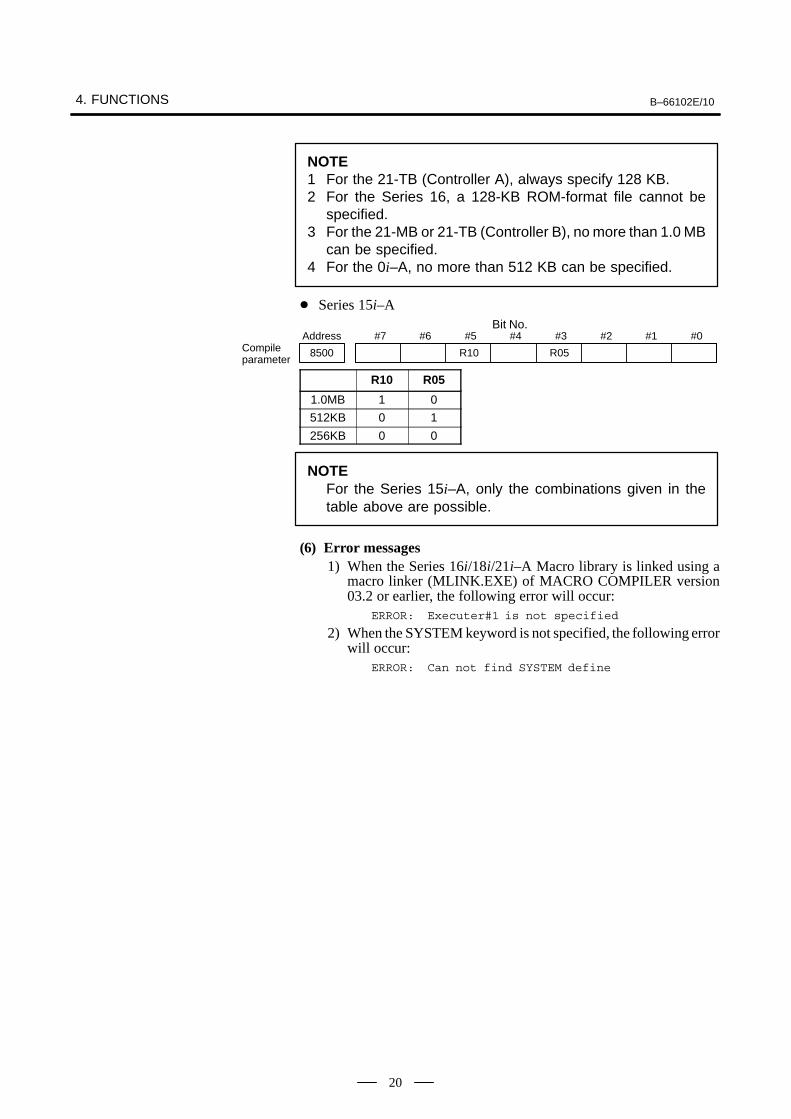
NOTE1 For the 21-TB (Controller A), always specify 128 KB.2 For the Series 16, a 128-KB ROM-format file cannot be
specified.3 For the 21-MB or 21-TB (Controller B), no more than 1.0 MB
can be specified.4 For the 0i–A, no more than 512 KB can be specified.
� Series 15i–ABit No.
#7 #6 #5 #4 #3 #2 #1 #0Address
8500 R10 R05Compileparameter
R10 R05
1.0MB 1 0
512KB 0 1
256KB 0 0
NOTEFor the Series 15i–A, only the combinations given in thetable above are possible.
(6) Error messages1) When the Series 16i/18i/21i–A Macro library is linked using a
macro linker (MLINK.EXE) of MACRO COMPILER version03.2 or earlier, the following error will occur:
ERROR: Executer#1 is not specified
2) When the SYSTEM keyword is not specified, the following errorwill occur:
ERROR: Can not find SYSTEM define
B–66102E/10 4. FUNCTIONS
21
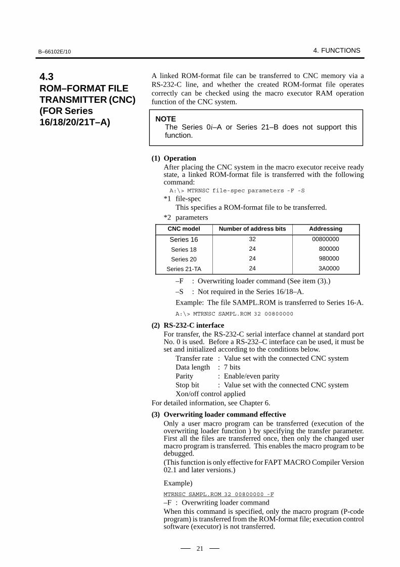
A linked ROM-format file can be transferred to CNC memory via aRS-232-C line, and whether the created ROM-format file operatescorrectly can be checked using the macro executor RAM operationfunction of the CNC system.
NOTEThe Series 0i–A or Series 21–B does not support thisfunction.
(1) OperationAfter placing the CNC system in the macro executor receive readystate, a linked ROM-format file is transferred with the followingcommand:A:\> MTRNSC file-spec parameters -F -S
*1 file-specThis specifies a ROM-format file to be transferred.
*2 parameters
CNC model Number of address bits Addressing
Series 16
Series 18
Series 20
Series 21-TA
32
24
24
24
00800000
800000
980000
3A0000
–F : Overwriting loader command (See item (3).)
–S : Not required in the Series 16/18–A.
Example: The file SAMPL.ROM is transferred to Series 16-A.
A:\> MTRNSC SAMPL.ROM 32 00800000
(2) RS-232-C interfaceFor transfer, the RS-232-C serial interface channel at standard portNo. 0 is used. Before a RS-232–C interface can be used, it must beset and initialized according to the conditions below.
Transfer rate : Value set with the connected CNC systemData length : 7 bitsParity : Enable/even parityStop bit : Value set with the connected CNC systemXon/off control applied
For detailed information, see Chapter 6.
(3) Overwriting loader command effectiveOnly a user macro program can be transferred (execution of theoverwriting loader function ) by specifying the transfer parameter.First all the files are transferred once, then only the changed usermacro program is transferred. This enables the macro program to bedebugged.(This function is only effective for FAPT MACRO Compiler Version02.1 and later versions.)
Example)
MTRNSC SAMPL.ROM 32 00800000 -F
–F : Overwriting loader commandWhen this command is specified, only the macro program (P-codeprogram) is transferred from the ROM-format file; execution controlsoftware (executor) is not transferred.
4.3ROM–FORMAT FILETRANSMITTER (CNC)(FOR Series16/18/20/21T–A)

4. FUNCTIONS B–66102E/10
22
a) Activate the P-code loader function in the initialization loaderfunction mode specified for the CNC (bit 1 of parameter No. 8701= 0) to transfer all files from the personal computer.MTRNSC SAMPL.ROM 32 00800000
b) Debug the macro program.c) If an error is found, correct the macro program and compile or
link the macro program to create the ROM-format file again.d) Activate the P-code loader function in the overwriting loader
function mode specified for the CNC (bit 1 of parameter No. 8701= 1). Specifying -F transfers the macro program from thepersonal computer.MTRNSC SAMPL.ROM 32 00800000 -F
Repeat steps b), c), and d) to debug the macro program.
If the library to be linked has been modified according to the softwarerevision, the above procedure must be followed again from step a),transferring all files.

B–66102E/10 4. FUNCTIONS
23
(1) OperationA linked ROM-format file is transferred to the FANUC PMC
Writer or FANUC FA Writer via a RS-232-C line, and is written toa macro ROM and verified.
A:\> MROMWT file-spec parametersWrite or write/verification
A:\> MROMVF file-spec parametersVerification
*1 file-specThis specifies a ROM-format file to be transferred.
*2 parameters
-K1xx : Cassette type (1)-K2xx : Cassette type (2)-IDxxxx: ID code-VCxx : Sets Vcc (with MROMWT only).-VPxx : Sets Vpp (with MROMWT only).-Pxx : Sets pulse width (with MROMWT only).-VF : Writes a ROM-format file, then verifies it (with
MROMWT only).For detailed information, see Appendix C.Example: The file SAMPL.ROM is written to a Series 0 512K-byte
ROM cassette, then is verified.
A:\> MROMWT SAMPL.ROM –K110 –K223 –ID50B2–VCC0 –VP64 -P01 -VF
(2) RS-232-C interfaceFor detailed information, see Chapter 6.
4.4ROM–FORMAT FILETRANSMITTER(FANUC PMCWRITER/FANUC FAWRITER)(FOR Series 0, 15–A,16–A, 18–A)

4. FUNCTIONS B–66102E/10
24
(1) OperationA macro program is read from the CNC/SYSTEM P via a RS-232-Cline, then is stored in an MS-DOS text file for the macro compiler.A macro program is transferred from the CNC/SYSTEM P after thecommand below is entered and the personal computer is placed inreceive ready state.
A:\> MPLOADA file-spec
1* file-spec
This specifies the name of a text file for storing a macro program.Example: A macro program is read to
A:\MCOMP\USR\TEST\ABC.SRC.
A:\> MPLOADA A:\MCOMP\USR\TEST\ABC.SRC
CAUTIONSelect the ISO code as output code when transferring amacro program from the CNC/SYSTEM P.
(1) OperationA macro program output with the parameter -L3 described in Section4.1 can be output to the CNC/SYSTEM P via a RS-232-C line. Afterthe CNC/SYSTEM P is placed in program read ready state, a macroprogram is transferred by the command below.
A:\> MPOUT file-spec parameters
*1 file-specThis specifies a macro program file to be transferred.
*2 parameters
–Fffff : Outputs fields (null code) before and after a macroprogram. By ffff, specify the number of fields to beoutput.
–CR : Specifies the output format of the EOB (;).When -CR is omitted:The EOB (;) is converted toLF(0AH)/CR(0DH)/CR(0DH).When -CR is specified:The EOB (;) is converted toLF(0AH).
(2) RS-232-C interfaceFor detailed information, see Chapter 6.
4.5SERIAL INTERFACEUTILITY
4.5.1Macro Program Input
4.5.2Macro Program Output

B–66102E/10 4. FUNCTIONS
25
(1) OperationA linked ROM-format file is transferred to the FANUC FA Writer viaa GP-IB interface, and is written to a macro cassette and verified.Since a linked ROM-format file is transferred to the FANUC FAWriter via a GP-IN interface, the file can be written to a macro cassetteand verified at higher speed than when the file is transferred via aRS-232-C line (Section 4.4).
A:\> MROMWTG file-spec parametersWrite or write/verification
A:\> MROMVFG file-spec parametersVerification
*1 file-specThis specifies a ROM-format file to be transferred.
*2 parameters
-K1xx : Cassette type (1)
-K2xx : Cassette type (2)
-IDxxxx : ID code
-VCxx : Sets Vcc (with MROMWTG only).
-VPxx : Sets Vpp (with MROMWTG only).
-Pxx : Sets pulse width (with MROMWTG only).
-VF : Writes a ROM-format file, then verifies it (withMROMWTG only).
For detailed information, see Appendix C.Example: The file SAMPL.ROM is written to a Series 0
512K-byte ROM cassette, then is verified.
A:\> MROMWTG SAMPL.ROM -K110 -K223-ID50B2 -VCC0 -VP64 -P01 -VF
(2) GP-IB interfaceFor detailed information, see Chapter 7.
4.6ROM–FORMAT FILETRANSMITTER(FANUC FA WRITER,GP–IB INTERFACE)(FOR Series 0, 15–A,16–A, 18–A)

4. FUNCTIONS B–66102E/10
26
(1) OperationConvert a ROM-format file created by the macro linker (MLINK) tothe memory-card format file which can be loaded from the memorycard using the boot function of the Series 15-B/16-B/20.
A:\> MMCARD file-spec(Series 16–B/16–C/18–B/18–C/20/21-B/16i–A/16i–B/18i–A/18i–B/21i–A/21i–B)
A:\> MMCARD15 file–spec (Series 15–B)
*1 file-specThis specifies a ROM-format File to be converted withoutextension. The name of MEM-format file is the same asROM-format File name with the extension .MEM.Example: A:\MCOMP\USR\TEST\SAMPL.ROM is
converted intoA:\MCOMP\USR\TEST\SAMPL.MEM.A:\> MMCARD15 A:\MCOMP\USR\TEST\SAMPL
Series 16-B/16–C/18-B/18–C/20/21-B/16�–A/16�–B/18�–A/18�–B/21�–A/21�–B/0�–A
Memory Card File
Macro Library File
Link Control File
LinkControl
(xxx.LNK)
ROM File
(xxx.ROM)
To memory cardCOPY A:xxx.MEM F: (F: Memory card device number)
Source File
MacroProgram
(xxx.SRC)
Object File
ObjectProgram
(xxx.REL)
MLINK
(Sereis 15-B)
MCOMP15
MacroLibrary
(xxx.MEX)MMCARD
(Sereis 15-B)
MMCARD15
MemoryCard File
(xxx.MEM)
Memory Card
Series 16-B/16–C/18-B/18–C/20/21-B/16�–A/16�–B/18�–A/18�–B/21�–A/21�–B
MCOMP0
(Sereis 15i–A)
MCOMP15I
MLINK15I
(Sereis 15i–A)
Series 15–B/16–B/16–C/18–B/18–C/20/21-B/16�–A/16�–B/18�–A/18�–B/21�–A/21�–B
(Sereis 15i–A)
MMCARD15I
4.7CONVERSION TO AMEMORY CARDFORMAT (MMCARD)(THIS FUNCTION ISUSED IN THE Series15–B/16–B/16–C/18–B/18–C/20/21–B/16i–A/18i–A/21i–A/16i–B/18i–B/21i–B/0i–A.)

B–66102E/10 5. SYMBOLIC MACRO PROGRAM
27
5 �� ���� ���� ������
A macro program is to be created according the rule described below.
(1) A macro program must start with address O. Address % must bespecified at the end of the file. Multiple programs can be coded in asingle file. At this time, the start of each program can be identifiedby address O. Data after address %, if any, is ignored. When multipleprograms are coded, address % must be coded at the end.
O0001 #101=1;
G00 X#101;
:
O0002 G243 X0 YX (ABS);
#500=#501+#502;
:
%
(2) One line can contain only one block. The end of block (EOB) isrepresented by a semicolon (;). All data after a semicolon on a lineis regarded as a comment.
#100=#101; COMMENTG00 X123. Y234. ; G01 ; => ”G01 ;” after ; is regarded as comment.
(3) All data after /� is regarded as a comment. A line starting with /* isregarded as a comment line; such a line is not compiled.
/� comment => Compiler ignores this line as comment line./� comment
/�
O0001 ;
/� comment => Compiler ignores this line as comment line.G00 ...;
;/� comment => Blank block containing only ; is created.M99;
%
(4) Programming using symbolic namesA symbolic name can be defined for a variable, expression, orcharacter string to allow programming using symbolic names. Asymbolic name can be defined as described below.

5. SYMBOLIC MACRO PROGRAM B–66102E/10
28
Symbolic name definition@xxxx yyyyyy
xxxx: Symbolic name(String of alphanumeric characters beginning with an alphabetic character)
Version of the compiler Version 1.4 or pre-vious versions
Version 2.1 or subse-quent versions
Maximum number ofcharacters
8 32
yyyyyy: Definition character string (not longer than 80 characters)
After a symbolic name is defined, the symbolic name used in a programis replaced by the corresponding definition character string.
Example)@COUNT1 #100
@ON =1
@OFF =0
@CURSOR #8505
@RETURN M99
/�
O0001 ; ==>> O0001 ;
CURSOR ON ; #8505 =1 ;
COUNT1 = COUNT1+1 ; #100 = #100+1 ;
RETURN ; M99 ;
(5) Symbolic name for sequence numberA symbolic name can be assigned to a sequence number as describedbelow. In (4) above, a symbolic name is just used for a definitioncharacter string. On the other hand, a symbolic name for a sequencenumber is regarded as a sequence number when it is coded at the startof a block, and is regarded as a jump (GOTO) destination numberwhen it is coded at a position other than the start of a block.
Definition of symbolic name for sequence number>xxxx 9999
xxxx: Symbolic name for sequence number(String of alphanumeric characters beginning with an alphabeticcharacter)
Version of the compiler Version 1.4 or previous versions
Version 2.1 or subsequent versions
Maximum number ofcharacters
8 32
9999: Number (not longer than four digits)After a symbolic name is defined, the symbolic name used in a programis replaced by the corresponding sequence number.
B–66102E/10 5. SYMBOLIC MACRO PROGRAM
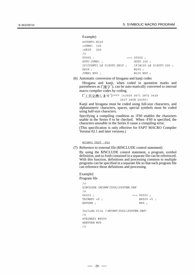
29
Example)@COUNT1 #100
>JUMP1 100
>SKIP 200
/�
O0002 ; ==> O0002 ;
GOTO JUMP1 ; GOTO 100 ;
IF[COUNT1 LE 0]GOTO SKIP ; IF[#100 LE 0]GOTO 200 ;
SKIP ; N200 ;JUMP1 M99 ; N100 M99 ;
(6) Automatic conversion of hiragana and kanji codesHiragana and kanji, when coded in quotation marks and
parentheses as (’ ’), can be auto-matically converted to internalmacro compiler codes by coding.
(’ ’) ==> (�3929 3671 3872 3439
2437 245E 2439�)
Kanji and hiragana must be coded using full-size characters, andalphanumeric characters, spaces, special symbols must be codedusing half-size characters.Specifying a compiling condition as -FS0 enables the charactersusable in the Series 0 to be checked. When -FS0 is specified, thecharacters unusable in the Series 0 cause a compiling error.(This specification is only effective for FAPT MACRO CompilerVersion 02.1 and later versions.)
MCOMP0 TEST -FS0
(7) Reference to external file ($INCLUDE control statement)By using the $INCLUDE control statement, a program, symboldefinition, and so forth contained in a separate file can be referenced.With this function, definitions and processing common to multipleprograms can be specified in a separate file so that each program filecan reference those definitions and processing.
Example)Program file/�
$INCLUDE \MCOMP\TOOL\SYSTEM.DEF/�
O0003 ; ==> O0003 ;
TAIWAP1 =5 ; #8500 =5 ;
RETURN ; M99 ;
Include file (\MCOMP\TOOL\SYSTEM.DEF)
/�
@TAIWAP1 #8500
@RETURN M99
/�
5. SYMBOLIC MACRO PROGRAM B–66102E/10
30
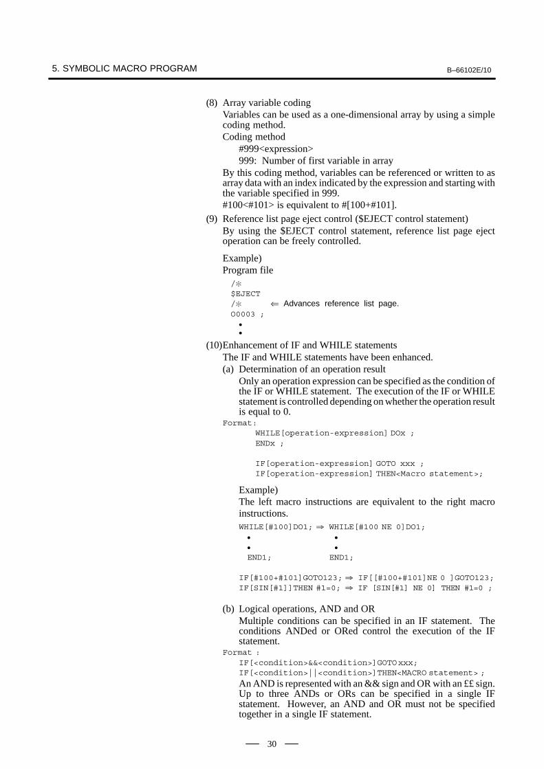
(8) Array variable codingVariables can be used as a one-dimensional array by using a simplecoding method.Coding method
#999<expression>999: Number of first variable in array
By this coding method, variables can be referenced or written to asarray data with an index indicated by the expression and starting withthe variable specified in 999.#100<#101> is equivalent to #[100+#101].
(9) Reference list page eject control ($EJECT control statement)By using the $EJECT control statement, reference list page ejectoperation can be freely controlled.
Example)Program file/�$EJECT/� ⇐ Advances reference list page.O0003 ;
�
�
(10)Enhancement of IF and WHILE statementsThe IF and WHILE statements have been enhanced.(a) Determination of an operation result
Only an operation expression can be specified as the condition ofthe IF or WHILE statement. The execution of the IF or WHILEstatement is controlled depending on whether the operation resultis equal to 0.
Format:WHILE[operation-expression] DOx ;ENDx ;
IF[operation-expression] GOTO xxx ;IF[operation-expression] THEN<Macro statement>;
Example)The left macro instructions are equivalent to the right macroinstructions.WHILE[#100]DO1; � WHILE[#100 NE 0]DO1;
� �
� �
END1; END1;
IF[#100+#101]GOTO123; � IF[[#100+#101]NE 0 ]GOTO123;IF[SIN[#1]]THEN #1=0; � IF [SIN[#1] NE 0] THEN #1=0 ;
(b) Logical operations, AND and ORMultiple conditions can be specified in an IF statement. Theconditions ANDed or ORed control the execution of the IFstatement.
Format :IF[<condition>&&<condition>]GOTOxxx;IF[<condition>||<condition>]THEN<MACRO statement> ;
An AND is represented with an && sign and OR with an ££ sign.Up to three ANDs or ORs can be specified in a single IFstatement. However, an AND and OR must not be specifiedtogether in a single IF statement.

B–66102E/10 5. SYMBOLIC MACRO PROGRAM
31
IF[<condition>&&<condition>&&<condition>&&<condition>] THEN<MACRO stmnt>; –OKIF[<condition>||<condition>||<condition>||<condition>]GOTO xxx; –OKIF[<condition>&&<condition>||<condition>]GOTO xxx ; –NG
Example)IF[#100 EQ 1 && #101 GT 0] GOTO 100 ;IF[#100 E Q1 ||#101 NE 1 || #102 GT 10 ] THEN #102=1 ;
(c) IF/THEN/ELSE/ENDIFThe syntax of an IF statement has been enhanced. Structuredprogramming is possible using IF/THEN/ELSE/ENDIF.The following shows the formats of syntactically valid IFstatements.� IF[...]GOTO 999 ;
� IF[...]THEN Macro-st ;
� IF[...]THEN Macro-st; *Macro-st:ELSE Macro-st; Macro statement
� IF[...]THEN ;Statement ; *Statement:
� Macro or NC statement�
ENDIF ;
� IF[...]THEN ;Statement ;
�
�
ELSE ;Statement ;
�
�
ENDIF ;
a) When only a single macro statement is to be executed, the macrostatement can be specified immediately after THEN/ELSE asshown in � and �.
IF[#100 EQ 0] THEN #101 = 1;ELSE #101 = 2;
b) When an instruction to be executed is an NC statement ormultiple instructions to be executed, the NC statement ormultiple instructions must be specified between theTHEN/ELSE line and ENDIF line as shown in � and �.
IF[#100 EQ 0] THEN ;GO1 X100 Y200 ;ENDIF ;
When instructions with THEN and ELSE must be executed asshown in �, the IF statement can be specified by combining theformats in a) and b).

5. SYMBOLIC MACRO PROGRAM B–66102E/10
32
IF[#100 EQ 0] THEN #101 = 1;
ELSE ;
#101 = 2 ;
GOO X#103 ;
ENDIF ;
Up to three levels of nesting of the IF statement are allowed.
IF [...] THEN ;
IF [...] THEN ;
Statement ;
�
�
ELSE ;IF [...] THEN ;
Statement ;
ENDIF ;
ENDIF ;
Statement ;
�
�
ELSE ;
Statement ;
�
�
ENDIF ;
CAUTIONWhen only a single macro statement is to be executed, themacro statement can be specified immediately afterTHEN/ELSE. In this case, no ENDIF statement is usuallyrequired. However, an ENDIF statement is required whenIF [...] THEN Macro-st ; is specified just before ELSE orENDIF of the previous nesting as shown below:IF [...] THEN ;
IF [...] THEN Macro-st ;
IF [...] THEN Macro-st ;
ENDIF ; �The ENDIF line is requiredELSE ; because IF [...] THEN
Macro-st ; is specified just before ELSE or ENDIF of
the previous nesting.
IF [...] THEN Macro-st ;
IF [...] THEN Macro-st ;
ENDIF ; �The ENDIF line is required ENDIF ; because IF [...] THEN
Macro-st ; is specified justbefore ELSE or ENDIF ofthe previous nesting.

B–66102E/10 6. RS-232-C INTERFACE SETTING
33
6 �������� ��������� �������
To transfer a ROM-format file to the CNC system or FANUCPMC-Writer/FA-Writer for writing to ROM/verification or transfer amacro program, the RS-232-C interface is controlled using the DOSfunction call (21H) auxiliary I/O device (AUX) for MS-DOS. By devicespecification with CONFIG.SYS, enable RS-232-C ports to be controlledwith the auxiliary I/O device (AUX).
The RS-232-C interface must be set or initialized beforehand accordingto the conditions described below. If a transfer operation is onceperformed via a RS-232-C interface, and the RS-232-C is used again withthe same or another command, the RS-232-C interface must beinitialized.
Transfer rate : Value set with the connected CNC systemData length : 7 bitsParity : Enable/even parityStop bit : Value set with the connected CNC systemXon/off control
System installation processing creates, for use by the user, a standardbatch file for RS-232-C interface initialization under the directory\MCOMP\TOOL.
(1) For Fujitsu FMR Series (\MCOMP\TOOL\RSFMR.BAT)Contents : SETUP RSC R0,4800,BITS-7,
PARITY-EVEN.STOP-2,XON
(2) For NEC PC98 Series (\MCOMP\TOOL\RSPC98.BAT)Contents : SPEED RS232-0 4800 BITS-7 PARITY-EVEN
STOP-2 XON
(3) For IBM PC-AT Series (\MCOMP\TOOL\RSPCAT.BAT)Contents : MODE COM1:48,E,7,2

7. GP-IB INTERFACE SETTING (FOR Series 0, 15–A, 16–A, 18–A) B–66102E/10
34
7����� ��������� �������
���� ������ �� ����� � ��� �!���
The GP-IB interface performs interface processing by using a GP-IBBIOS driver provided by each personal computer supplier. The user is toprepare a GP-IB interface board for a personal computer model to use, andto initialize the board according to the operator’s manual before usage.
(1) GP-IB interface boardUse the GP-IB interface boards listed below.(a) NEC PC98 Series
NEC GP-IB (IEEE-488) interface board (PC-9801-29N)(b) IBM PC-AT Series
NATIONAL INSTRUMENTSVAT-GPIB Interface & NI-488.2 MS-DOS/NI-488.2 WindowGsSoftwareWFD3/FD5 NO.776207-1
(2) GP-IB interface board setting(a) Set the GP-IB address to 1E (hexadecimal).
When an address other than 1E is to be used for some reason, thesame address must be set in the parameter -MAxx of theROM-format file transmitter command(MROMWTG/MROMVFG).When GP-IB address OF is set:A:\> MROMWTG SAMPL.ROM -K110 -K223 -ID40B0 -MA0F
(b) Select the master mode rather than the slave mode.The master mode must be selected because the GP-IB controlfunction is performed on the personal computer.
(c) OthersFor other settings, refer to the operator’s manual of each GP-IBboard.
(3) FANUC FA Writer setting(a) Set the GP-IB address to 00 (hexadecimal).
The address is factory-set to 00.(b) Set the transfer block size to 2058 bytes.
The block size is factory-set to 256 bytes.
(4) Switching the interface of the FANUC FA Writer
(a) Switching the interface of the FANUC FA Writer to a GPIBinterface.To switch the interface, turn on the power to the FANUC FAWriter while pressing the FUNCTION key. The FANUC FAWriter then enters the GPIB interface mode.

B–66102E/10 8. SYSTEM COMMON SYMBOL DEFINITION FILE
35
8 ����� �� �� �� �� "��������� ���
When the system is installed, a system common symbol definition file isstored under the directory \MCOMP\TOOL. For macro programcreation, the user should make full use of the symbolic names defined inthe file for variables commonly used with the system.
System common symbol definition fileFile name: \MCOMP\TOOL\SYSTEM.DEF
To use this file, use the external file reference function described in Item(7) in Chapter 5. For a usage example, see Appendix D.
$INCLUDE \MCOMP\TOOL\SYSTEM.DEF
For information about the defined symbols, see Appendix A.
9. HOW TO VIEW REFERENCE LIST/COMPILE LIST B–66102E/10
36
9 #�$ �� %��$ ��������� ���&�� ��� ���
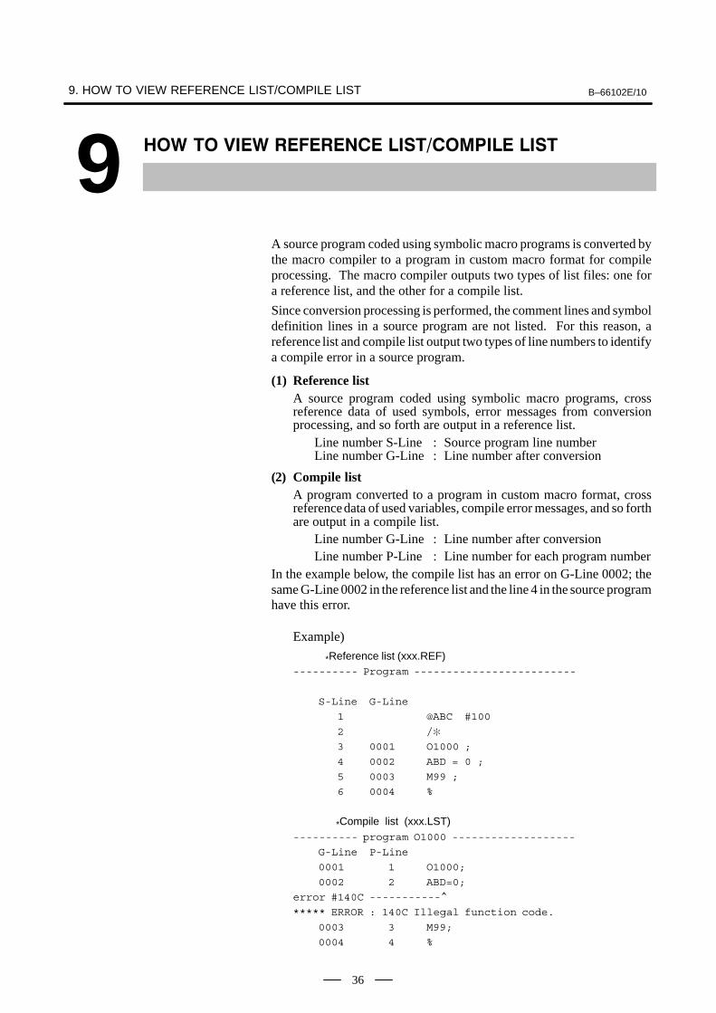
A source program coded using symbolic macro programs is converted bythe macro compiler to a program in custom macro format for compileprocessing. The macro compiler outputs two types of list files: one fora reference list, and the other for a compile list.
Since conversion processing is performed, the comment lines and symboldefinition lines in a source program are not listed. For this reason, areference list and compile list output two types of line numbers to identifya compile error in a source program.
(1) Reference listA source program coded using symbolic macro programs, crossreference data of used symbols, error messages from conversionprocessing, and so forth are output in a reference list.
Line number S-Line : Source program line numberLine number G-Line : Line number after conversion
(2) Compile listA program converted to a program in custom macro format, crossreference data of used variables, compile error messages, and so forthare output in a compile list.
Line number G-Line : Line number after conversionLine number P-Line : Line number for each program number
In the example below, the compile list has an error on G-Line 0002; thesame G-Line 0002 in the reference list and the line 4 in the source programhave this error.
Example)
*Reference list (xxx.REF)---------- Program -------------------------
S-Line G-Line
1 @ABC #100
2 /�
3 0001 O1000 ;
4 0002 ABD = 0 ;
5 0003 M99 ;
6 0004 %
*Compile list (xxx.LST)---------- program O1000 -------------------
G-Line P-Line
0001 1 O1000;
0002 2 ABD=0;
error #140C -----------^
***** ERROR : 140C Illegal function code.
0003 3 M99;
0004 4 %

APPENDIX


B–66102E/10A. SYSTEM COMMON SYMBOL DEFINITION
(\MCOMP\TOOL\SYSTEM.DEF)APPENDIX
39
A����� �� �� �� �� "���������
�' �� �'���'����� ("���
� SYSTEM. DEF for series 0/16/18/20/21$NOLIST
/�
/� **************************************************************
/� * System common symbol define *
/� * for series 0/16/18/20/21. (V01.03 1999.07.21) *
/� **************************************************************
/�
/�
/� No.01 Control instruction code.
/� ~~~~~~~~~~~~~~~~~~~~~~~~~~~~~~~~
@CALL M98P /� Sub program call.
@RETURN M99 /� Return to main program.
@RETURNP M99P /� Return to main program with sequence No.
/�
@DISPLAY G243 /� Character display.
@FORM F /� Format.
@DATA D /� Data.
@NSUP Z0 /� No Zero suppress.
@ZSUP Z1 /� Zero suppress.
/�
@ELASE G202 /� CRT erase.
@ELASEGR G202P1 /� Graphic erase.
@ELASECH G202P2 /� Charactor erase.
@ELASEAL G202P3 /� Graphic & Character erase.
/�
@RECTNG G204 /� Rectangle display.
/�
@GRPNT G206 /� Graphic paint out.
/�
@COLOR G240 /� Display color select.
@BLACK G240P0 /� Black.
@RED G240P1 /� Red.
@GREEN G240P2 /� Green.
@YELLOW G240P3 /� Yellow.
@BLUE G240P4 /� Blue.
@PERPLE G240P5 /� Perple.
@SKYBL G240P6 /� Sky–blue.
@WHITE G240P7 /� White.
@REDR G240P–1 /� Reverse Red.
@GREENR G240P–2 /� Reverse Green.
@YELLOWR G240P–3 /� Reverse Yellow.
@BLUER G240P–4 /� Reverse Blue.
@PERPLER G240P–5 /� Reverse Perple.
@SKYBLR G240P–6 /� Reverse Sky–blue.
@WHITER G240P–7 /� Reverse White.
/�
@BON L1 /� Blink ON
@BOF L0 /� Blink OFF

A. SYSTEM COMMON SYMBOL DEFINITION (\MCOMP\TOOL\SYSTEM.DEF) B–66102E/10APPENDIX
40
/�
@DRLINEK G244 /� Graphic Line kind select.
@DRSTART G242 /� Draw start point.
@DRLINE G01 /� Linear line display.
@DRCW G02 /� Circle display(CW).
@DRCCW G03 /� Circle display(CCW).
/�
@GRCSR G249 /� Graphic cursor.
/�
@PMCDATA G310 /� PMC relay/data read and write. @1BYTE L1 /� 1 BYTE
@2BYTE L2 /� 2 BYTE
@4BYTE L4 /� 4 BYTE
/�
@TRSVR G315 /� P–code variable transfer.
@TRSVRNML G315P001/� normal transfer.
@TRSVRUPT G315P002/� up transfer.
@TRSVRDWT G315P003/� down transfer.
@TRSVRARG G315P101/� transfer to arangement.
@TRSVRUPA G315P102/� up transfer to arangement.
@TRSVRDWA G315P103/� down transfer to arangement.
/�
@PAMAKE G320 /� CNC Prog. access. (Prog. make) @PADELET G321 /� (Prog. delete)
@PACNDNS G322 /� (Prog. condense)
@PAREAD G325 /� (Block read)
@PAWRITE G326 /� (Block write)
@PABDELT G327 /� (Block delete)
@PACREAD G328 /� (Character block read)
@PACWRIT G329 /� (Character block write)
/�
@RSOPEN G330 /� RS232C open.
@RSCLOSE G331 /� close.
@RSRECV G335 /� receive 1ch.
@RSSEND G336 /� Data send. @RSVARRD G337 /� Variable data read.
@RSVARWT G338 /� Variable data write.
@RSFUNC G339 /� FANUC cassettee control.
/�
@PMAFEED G340 /� PMC AXIS feed.
@PMACUT G341 /� cutting.
@PMADWLL G344 /� dwell.
@PMAREFC G345 /� reference position return.
@PMAMSCL G346 /� miscellaneous function.
@PMASNRD G348 /� signal read.
@PMASNWT G349 /� signal write.
/�
/�/� No.02 Conversation MACRO (TAIWA MACRO) control Variable define.
/� ~~~~~~~~~~~~~~~~~~~~~~~~~~~~~~~~~~~~~~~~~~~~~~~~~~~~~~~~~~~~~~~~
@CMACRO1 #8500 /� Conversation MACRO – 1 MAIN PROGRAM No.
@TAIWAP1 #8500
@CMACRO2 #8550 /� Conversation MACRO – 2 MAIN PROGRAM No.
@TAIWAP2 #8550
@CMACRO3 #8551 /� Conversation MACRO – 3 MAIN PROGRAM No.
@TAIWAP3 #8551
/�

B–66102E/10A. SYSTEM COMMON SYMBOL DEFINITION
(\MCOMP\TOOL\SYSTEM.DEF)APPENDIX
41
@KEYCONT #8502 /� MDI–KEY IN CONTROL.
@NOREAD #8502=0 /� No Data read.
@NUMREAD #8502=1 /� Numeric Data read.
@ADRREAD #8502=2 /� Address+Numeric Data read.
@ASCREAD #8502=3 /� ASCII Data read.
/�
@KEYCODE #8501 /� MDI–KEY IN CODE.
@PAGEDW 1 /� ”Page Down” KEY pushed.
@PAGEUP 2 /� ”Page Up”
@CURDW 3 /� ”Cursor Down” @CURUP 4 /� ”Cursor Up”
@ALTER 5 /� ”Alter”
@INSRT 6 /� ”Insert”
@DELET 7 /� ”Delete”
@INPUT 8 /� ”Input”
@START 9 /� ”Start/Output”
@RESET 10 /� ”Reset”
@CURRT 18 /� ”Cursor Right”
@CURLF 19 /� ”Cursor Left”
@PINPUT 28 /� ”Input” add decimal point
/�
@SFTLF 11 /� ”Soft key left” (9”CRT)
@SFT1 12 /� ”Soft key 1” (9”CRT) @SFT2 13 /� ”Soft key 2” (9”CRT)
@SFT3 14 /� ”Soft key 3” (9”CRT)
@SFT4 15 /� ”Soft key 4” (9”CRT)
@SFT5 16 /� ”Soft key 5” (9”CRT)
@SFTRT 17 /� ”Soft key right” (9”CRT)
/�
@SFTFLF 20 /� ”Soft key left” (14”CRT)
@SFTF1 21 /� ”Soft key 1” (14”CRT)
@SFTF2 22 /� ”Soft key 2” (14”CRT)
@SFTF3 23 /� ”Soft key 3” (14”CRT)
@SFTF4 24 /� ”Soft key 4” (14”CRT)
@SFTF5 25 /� ”Soft key 5” (14”CRT) @SFTF6 26 /� ”Soft key 6” (14”CRT)
@SFTF7 27 /� ”Soft key 7” (14”CRT)
@SFTF8 28 /� ”Soft key 8” (14”CRT)
@SFTF9 29 /� ”Soft key 9” (14”CRT)
@SFTF10 30 /� ”Soft key 10” (14”CRT)
@SFTFRT 31 /� ”Soft key right” (14”CRT)
@KEYDATA #8503 /� MDI–KEY IN DATA.
@KEYADRS #8504 /� MDI–KEY IN ADDRESS.
@KEYARRY #8552 /� MDI–KEY SPECIAL READ DATA VAR. No.
/�
@CURSOR #8505 /� CURSOR DISPLAY CONTROL.
@CURSORX #8506 /� CURSOR DISPLAY POSITION (X). @CURSORY #8507 /� CURSOR DISPLAY POSITION (Y).
/�
@CHRPROG #8509 /� CHARACTER DEFINE PROGRAM No.
@CRTFUNC #8510 /� CRT FUNCTION CONTROL.
/�
@ARRY2BS #8512 /� Array CONTORL
@ARRY3BS #8513 /� Array CONTORL
@ARRY1CT #8516 /� Array CONTORL
@ARRY2CT #8517 /� Array CONTORL

A. SYSTEM COMMON SYMBOL DEFINITION (\MCOMP\TOOL\SYSTEM.DEF) B–66102E/10APPENDIX
42
@ARRYTOP #8519 /� Array CONTORL (Top variable No.)
/�
@TRNSDAT #8511 /� Transfer CONTORL
@TRNS2BS #8512 /� Transfer CONTORL
@TRNS3BS #8513 /� Transfer CONTORL
@TRNS2TO #8514 /� Transfer CONTORL
@TRNS3TO #8515 /� Transfer CONTORL
/�
@PAPROGN #8520 /� CNC PROG. ACCESS. (PROGRAM No.)
@PABLOKN #8521 /� CNC PROG. ACCESS. (BLOCK No.) @PAVARNO #8522 /� CNC PROG. ACCESS. (DATA VAR. No.)
@PAPNTVN #8523 /� CNC PROG. ACCESS. (POINT DATA VAR. No.)
@PAERROR #8529 /� CNC PROG. ACCESS. (RETURN CODE)
/�
@PABGEDT #8526 /� BG–edit status.
@PAPGCNT #8527 /� Program count.
@PAFPMEM #8528 /� Free program memory.
/�
@RSERROR #8539 /� RS232C INTERFACE (RETURN CODE)
/�
@MDIKEYI #8549 /� MDI Key image
/�
@CUTTIME #8553 /� Cutting Time. @CUTLENG #8554 /� Cutting length.
/�
@HELPPNM #8555 /� User’s HELP screen Prog. Num.
@HELPRST #8556 /� User’s HELP return status.
/�
@KEYLINX #8561 /� KEY in line X potion.
@KEYLINY #8562 /� KEY in line Y potion.
@KEYINUM #8563 /� KEY input number.
@KEYPRPT #8564 /� KEY in line prompt.
@KEYCLOR #8565 /� KEY in line color.
/�
@ITLCNTL #8600 /� Inter Lock control. @ITLSTTS #8601 /� Skip signal movement direction.
/�
@PMGSLCT #8602 /� PMC AXIS select. (G–code control)
/�
@PCDWKNO #8610 /� P–code Work No. search.
/�
@TRQLTO1 #8621 /� AXIS 1 limited torque override.
@TRQLTO2 #8622 /� AXIS 2
@TRQLTO3 #8623 /� AXIS 3
@TRQLTO4 #8624 /� AXIS 4
@TRQLTO5 #8625 /� AXIS 5
@TRQLTO6 #8626 /� AXIS 6
@TRQLTO7 #8627 /� AXIS 7 @TRQLTO8 #8628 /� AXIS 8
/�
@CNVTAD1 #8631 /� CHANNEL 1 A/D converter.
@CNVTAD2 #8632 /� CHANNEL 2
@CNVTAD3 #8633 /� CHANNEL 3
@CNVTAD4 #8634 /� CHANNEL 4
/�
@MSKCLAX #8690 /� AXIS Macro call mask.
@MSKCLTC #8691 /� T code call mask.

B–66102E/10A. SYSTEM COMMON SYMBOL DEFINITION
(\MCOMP\TOOL\SYSTEM.DEF)APPENDIX
43
/�
@PMVSLCT #8700 /� PMC AXIS select. (VARIABLE control)
@PMVFLG1 #8710 /� PMC 1 control flag.
@PMVCMD1 #8711 /� command.
@PMVCSP1 #8712 /� cutting speed.
@PMVLNG1 #8713 /� length.
@PMVSTS1 #8715 /� status.
@PMVFLG2 #8720 /� PMC 2 control flag.
@PMVCMD2 #8721 /� command.
@PMVCSP2 #8722 /� cutting speed. @PMVLNG2 #8723 /� length.
@PMVSTS2 #8725 /� status.
@PMVFLG3 #8730 /� PMC 3 control flag.
@PMVCMD3 #8731 /� command.
@PMVCSP3 #8732 /� cutting speed.
@PMVLNG3 #8733 /� length.
@PMVSTS3 #8735 /� status.
@PMVFLG4 #8740 /� PMC 4 control flag.
@PMVCMD4 #8741 /� command.
@PMVCSP4 #8742 /� cutting speed.
@PMVLNG4 #8743 /� length.
@PMVSTS4 #8745 /� status.
/� @WINDIDX #8998 /� Window Index.
@WINDDAT #8999 /� Window Data.
/�
/�
/� No.03 System Variable.
/� ~~~~~~~~~~~~~~~~~~~~~~~
@EMPTY #0 /� ”EMPTY”.
@ENMTY #0 /� ”EMPTY”.
@ALARM #3000 /� Alarm display.
@TIMER1 #3001 /� Msec Timer.
@TIMER2 #3002 /� Hour Timer.
@SBKCNT #3003 /� Single blok/Auxilialy function control. @FLDCNT #3004 /� Feed hold/Over ride control.
@SETTING #3005 /� Setting data.
@DATE #3011 /� System date.
@TIME #3012 /� System Time.
@PARTCNT #3901 /� Part count.
@PARTRQT #3902 /� Part request.
@MDLG01 #4001 /� Modal G–code Group 1
@MDLG02 #4002 /� Modal G–code Group 2
@MDLG03 #4003 /� Modal G–code Group 3
@MDLG04 #4004 /� Modal G–code Group 4
@MDLG05 #4005 /� Modal G–code Group 5
@MDLG06 #4006 /� Modal G–code Group 6
@MDLG07 #4007 /� Modal G–code Group 7 @MDLG08 #4008 /� Modal G–code Group 8
@MDLG09 #4009 /� Modal G–code Group 9
@MDLG10 #4010 /� Modal G–code Group 10
@MDLG11 #4011 /� Modal G–code Group 11
@MDLG12 #4012 /� Modal G–code Group 12
@MDLG13 #4013 /� Modal G–code Group 13
@MDLG14 #4014 /� Modal G–code Group 14
@MDLG15 #4015 /� Modal G–code Group 15
@MDLG16 #4016 /� Modal G–code Group 16

A. SYSTEM COMMON SYMBOL DEFINITION (\MCOMP\TOOL\SYSTEM.DEF) B–66102E/10APPENDIX
44
@MDLG17 #4017 /� Modal G–code Group 17
@MDLG18 #4018 /� Modal G–code Group 18
@MDLG19 #4019 /� Modal G–code Group 19
@MDLG20 #4020 /� Modal G–code Group 20
@MDLG21 #4021 /� Modal G–code Group 21
@MDLG22 #4022 /� Modal G–code Group 22
@CORDF #4109 /� F cord
@CORDM #4113 /� M cord
@SEQNUM #4114 /� Sequece number
@PRGNUM #4115 /� Program number @CORDS #4119 /� S cord
@CORDT #4120 /� T cord
/�
@ABSIO1 #5001 /� Block end position. 1’st
@ABSIO2 #5002 /� 2’nd
@ABSIO3 #5003
@ABSIO4 #5004
@ABSIO5 #5005
@ABSIO6 #5006
@ABSIO7 #5007
@ABSIO8 #5008
@ABSMT1 #5021 /� Machine Position.
@ABSMT2 #5022 @ABSMT3 #5023
@ABSMT4 #5024
@ABSMT5 #5025
@ABSMT6 #5026
@ABSMT7 #5027
@ABSMT8 #5028
@ABSOT1 #5041 /� Current absolute position.
@ABSOT2 #5042
@ABSOT3 #5043
@ABSOT4 #5044
@ABSOT5 #5045
@ABSOT6 #5046 @ABSOT7 #5047
@ABSOT8 #5048
@ABSKP1 #5061 /� Skip cutting position.
@ABSKP2 #5062
@ABSKP3 #5063
@ABSKP4 #5064
@ABSKP5 #5065
@ABSKP6 #5066
@ABSKP7 #5067
@ABSKP8 #5068
@OFSEXW1 #5201 /� AXIS 1 External workpiece reference offset.
@OFSEXW2 #5202 /� AXIS 2
@OFSEXW3 #5203 /� AXIS 3 @OFSEXW4 #5204 /� AXIS 4
@OFSEXW5 #5205 /� AXIS 5
@OFSEXW6 #5206 /� AXIS 6
@OFSEXW7 #5207 /� AXIS 7
@OFSEXW8 #5208 /� AXIS 8
@OFS54W1 #5221 /� AXIS 1 G54 workpiece reference offset.
@OFS54W2 #5222 /� AXIS 2
@OFS54W3 #5223 /� AXIS 3
@OFS54W4 #5224 /� AXIS 4

B–66102E/10A. SYSTEM COMMON SYMBOL DEFINITION
(\MCOMP\TOOL\SYSTEM.DEF)APPENDIX
45
@OFS54W5 #5225 /� AXIS 5
@OFS54W6 #5226 /� AXIS 6
@OFS54W7 #5227 /� AXIS 7
@OFS54W8 #5228 /� AXIS 8
@OFS55W1 #5241 /� AXIS 1 G55 workpiece reference offset.
@OFS55W2 #5242 /� AXIS 2
@OFS55W3 #5243 /� AXIS 3
@OFS55W4 #5244 /� AXIS 4
@OFS55W5 #5245 /� AXIS 5
@OFS55W6 #5246 /� AXIS 6 @OFS55W7 #5247 /� AXIS 7
@OFS55W8 #5248 /� AXIS 8
@OFS56W1 #5261 /� AXIS 1 G56 workpiece reference offset.
@OFS56W2 #5262 /� AXIS 2
@OFS56W3 #5263 /� AXIS 3
@OFS56W4 #5264 /� AXIS 4
@OFS56W5 #5265 /� AXIS 5
@OFS56W6 #5266 /� AXIS 6
@OFS56W7 #5267 /� AXIS 7
@OFS56W8 #5268 /� AXIS 8
@OFS57W1 #5281 /� AXIS 1 G57 workpiece reference offset.
@OFS57W2 #5282 /� AXIS 2 @OFS57W3 #5283 /� AXIS 3
@OFS57W4 #5284 /� AXIS 4
@OFS57W5 #5285 /� AXIS 5
@OFS57W6 #5286 /� AXIS 6
@OFS57W7 #5287 /� AXIS 7
@OFS57W8 #5288 /� AXIS 8
@OFS58W1 #5301 /� AXIS 1 G58 workpiece reference offset.
@OFS58W2 #5302 /� AXIS 2
@OFS58W3 #5303 /� AXIS 3
@OFS58W4 #5304 /� AXIS 4
@OFS58W5 #5305 /� AXIS 5
@OFS58W6 #5306 /� AXIS 6 @OFS58W7 #5307 /� AXIS 7
@OFS58W8 #5308 /� AXIS 8
@OFS59W1 #5321 /� AXIS 1 G59 workpiece reference offset.
@OFS59W2 #5322 /� AXIS 2
@OFS59W3 #5323 /� AXIS 3
@OFS59W4 #5324 /� AXIS 4
@OFS59W5 #5325 /� AXIS 5
@OFS59W6 #5326 /� AXIS 6
@OFS59W7 #5327 /� AXIS 7
@OFS59W8 #5328 /� AXIS 8
/�
/�
/� No.04 OTHER SYMBOL DEFINE./� ~~~~~~~~~~~~~~~~~~~~~~~~~~~
@ON =1
@OFF =0
/�
$LIST

A. SYSTEM COMMON SYMBOL DEFINITION (\MCOMP\TOOL\SYSTEM.DEF) B–66102E/10APPENDIX
46
� SYSTEM. DEF for series 15i0/16/18/20/21 (Possible to use this symbol definition evenby series 15B)$NOLIST/�
/� *************************************************************
/� * System common symbol define. */� * for series15i (V01.01 1999.07.21) *
/� *************************************************************
/�/�
/� No.01 Control instruction code./� ~~~~~~~~~~~~~~~~~~~~~~~~~~~~~~~~
@CALL M98P /� Sub program call.
@RETURN M99 /� Return to main program. @RETURNP M99P /� Return to main program with sequence No.
/�
@ELASE G202 /� CRT erase. @ELASEGR G202P1 /� Graphic erase.
@ELASECH G202P2 /� Charactor erase.
@ELASEAL G202P3 /� Graphic & Character erase./�
@COLOR G240 /� Display color select. @BLACK G240P0 /� Black.
@RED G240P1 /� Red.
@GREEN G240P2 /� Green. @YELLOW G240P3 /� Yellow.
@BLUE G240P4 /� Blue.
@PERPLE G240P5 /� Perple. @SKYBL G240P6 /� Sky–blue.
@WHITE G240P7 /� White.
@REDR G240P–1 /� Reverse Red. @GREENR G240P–2 /� Reverse Green.
@YELLOWR G240P–3 /� Reverse Yellow. @BLUER G240P–4 /� Reverse Blue.
@PERPLER G240P–5 /� Reverse Perple.
@SKYBLR G240P–6 /� Reverse Sky–blue. @WHITER G240P–7 /� Reverse White.
/�
@BON L1 /� Blink ON @BOF L0 /� Blink OFF
/�
@ABSMOD G390 /� Absolute mode @INCMOD G391 /� Incremental mode
/� @CURSOR G230 /� Cursor display control.
@CLEN L /� cirsor length
/� @DISPLAY G243 /� Character display.
@FORM F /� Format.
@DATA D /� Data. @NSUP Z0 /� No Zero suppress.
@ZSUP Z1 /� Zero suppress.
/� @KEYPRPT G280 /� Prompt display.
/�
@RECTNG G204 /� Rectangle display./�
@DRLINEK G244 /� Graphic Line kind select.

B–66102E/10A. SYSTEM COMMON SYMBOL DEFINITION
(\MCOMP\TOOL\SYSTEM.DEF)APPENDIX
47
@DRSTART G242 /� Draw start point.
@DRLINE G301 /� Linear line display.
@DRCW G302 /� Circle display(CW).
@DRCCW G303 /� Circle display(CCW).
/�
@PMCDATA G310 /� PMC relay/data read and write.
@1BYTE L1 /� 1 BYTE
@2BYTE L2 /� 2 BYTE
@4BYTE L4 /� 4 BYTE
/� @TRSVR G315 /� P–code variable transfer.
@TRSVRNML G315P001/� normal transfer.
@TRSVRUPT G315P002/� up transfer.
@TRSVRDWT G315P003/� down transfer.
@TRSVRARG G315P101/� transfer to arangement.
@TRSVRUPA G315P102/� up transfer to arangement.
@TRSVRDWA G315P103/� down transfer to arangement.
/�
@PAMAKE G370 /� CNC Prog. access. (Prog. make)
@PADELET G371 /� (Prog. delete)
@PAREAD G375 /� (Block read)
@PAWRITE G376 /� (Block write)
@PABDELT G377 /� (Block delete) @PACREAD G328 /� (Character block read)
@PACWRIT G329 /� (Character block write)
/�
@RSOPEN G330 /� RS232C open.
@RSCLOSE G331 /� close.
@RSRECV G335 /� receive 1ch.
@RSSEND G336 /� Data send.
@RSVARRD G337 /� Variable data read.
@RSVARWT G338 /� Variable data write.
@RSFUNC G339 /� FANUC cassettee control.
/�
@PMAFEED G340 /� PMC AXIS feed. @PMACUT G341 /� cutting.
@PMADWLL G344 /� dwell.
@PMAREFC G345 /� reference position return.
@PMAMSCL G346 /� miscellaneous function.
@PMASNRD G348 /� signal read.
@PMASNWT G349 /� signal write.
/�
/�
/� No.02 Conversation MACRO (TAIWA MACRO) control Variable define.
/� ~~~~~~~~~~~~~~~~~~~~~~~~~~~~~~~~~~~~~~~~~~~~~~~~~~~~~~~~~~~~~~~~
@CMACRO1 #8500 /� Conversation MACRO – 1 MAIN PROGRAM No.
@AMACRO1 #8600 /� Auxliary MACRO–1 MAIN PROGRAM No.
@TAIWAP1 #8500/�
@KEYCONT #8502 /� MDI–KEY IN CONTROL.
@NOREAD #8502=0 /� No Data read.
@NUMREAD #8502=1 /� Numeric Data read.
@ADRREAD #8502=2 /� Address+Numeric Data read.
@ASCREAD #8502=3 /� ASCII Data read.
/�
@KEYCODE #8501 /� MDI–KEY IN CODE.
@PAGEDW 1 /� ”Page Down” KEY pushed.
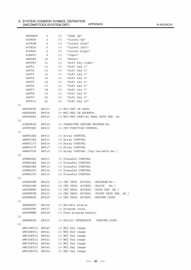
A. SYSTEM COMMON SYMBOL DEFINITION (\MCOMP\TOOL\SYSTEM.DEF) B–66102E/10APPENDIX
48
@PAGEUP 2 /� ”Page Up”
@CURUP 3 /� ”Cursor Up”
@CURDW 4 /� ”Cursor Down”
@CURLF 5 /� ”Cursor Left”
@CURRT 6 /� ”Cursor Right”
@INPUT 8 /� ”Input”
@RESET 10 /� ”Reset”
@SFTRT 11 /� ”Soft key right”
@SFT1 12 /� ”Soft key 1”
@SFT2 13 /� ”Soft key 2” @SFT3 14 /� ”Soft key 3”
@SFT4 15 /� ”Soft key 4”
@SFT5 16 /� ”Soft key 5”
@SFT6 17 /� ”Soft key 6”
@SFT7 18 /� ”Soft key 7”
@SFT8 19 /� ”Soft key 8”
@SFT9 20 /� ”Soft key 9”
@SFT10 21 /� ”Soft key 10”
/�
@KEYDATA #8503 /� MDI–KEY IN DATA.
@KEYADRS #8504 /� MDI–KEY IN ADDRESS.
@KEYARRY #8552 /� MDI–KEY SPECIAL READ DATA VAR. No.
/� @CHRPROG #8509 /� CHARACTER DEFINE PROGRAM No.
@CRTFUNC #8530 /� CRT FUNCTION CONTROL.
/�
@ARRY2BS #8512 /� Array CONTORL
@ARRY3BS #8513 /� Array CONTORL
@ARRY1CT #8516 /� Array CONTORL
@ARRY2CT #8517 /� Array CONTORL
@ARRYTOP #8519 /� Array CONTORL (Top variable No.)
/�
@TRNSDAT #8511 /� Transfer CONTORL
@TRNS2BS #8512 /� Transfer CONTORL
@TRNS3BS #8513 /� Transfer CONTORL @TRNS2TO #8514 /� Transfer CONTORL
@TRNS3TO #8515 /� Transfer CONTORL
/�
@PAPROGN #8520 /� CNC PROG. ACCESS. (PROGRAM No.)
@PABLOKN #8521 /� CNC PROG. ACCESS. (BLOCK No.)
@PAVARNO #8522 /� CNC PROG. ACCESS. (DATA VAR. No.)
@PAPNTVN #8523 /� CNC PROG. ACCESS. (POINT DATA VAR. No.)
@PAERROR #8529 /� CNC PROG. ACCESS. (RETURN CODE)
/�
@PABGEDT #8526 /� BG–edit status.
@PAPGCNT #8527 /� Program count.
@PAFPMEM #8528 /� Free program memory.
/� @RSERROR #8539 /� RS232C INTERFACE (RETURN CODE)
/�
@MDIKEYI0 #8540 /� MDI Key image
@MDIKEYI1 #8541 /� MDI Key image
@MDIKEYI2 #8542 /� MDI Key image
@MDIKEYI3 #8543 /� MDI Key image
@MDIKEYI4 #8544 /� MDI Key image
@MDIKEYI5 #8545 /� MDI Key image
@MDIKEYI6 #8546 /� MDI Key image

B–66102E/10A. SYSTEM COMMON SYMBOL DEFINITION
(\MCOMP\TOOL\SYSTEM.DEF)APPENDIX
49
@MDIKEYI7 #8547 /� MDI Key image
@MDIKEYI8 #8548 /� MDI Key image
@MDIKEYI9 #8549 /� MDI Key image
/�
@CUTTIME #8553 /� Cutting Time.
@CUTLENG #8554 /� Cutting length.
/�
@ITLCNTL #8605 /� Inter Lock control.
@ITLSTTS #8606 /� Skip signal movement direction.
/� @PMGSLCT #8602 /� PMC AXIS select. (G–code control)
/�
@PCDWKNO #8610 /� P–code Work No. search.
/�
@TRQLTID #8990 /� Limited torque override ID.
@TRQWT 100 /� write.
@TRQRD 101 /� read.
@TRQLTAX #8991 /� axis no.
@TRQLTVL #8992 /� value.(0–255)
@TRQLTER #8993 /� return code.
/�
@CNVADID1 #8997 /� A/D converter ID1.
@ADGEN 400 /� general. @ADSPDL 401 /� spindle.
@ADAXS 402 /� axis.
@CNVADID2 #8998 /� ID2.
@CNVADVAL #8999 /� value.
@CNVADERR #8996 /� return code.
/�
@MSKCLAX #8690 /� AXIS Macro call mask.
@MSKCLTC #8691 /� T code call mask.
/�
/�
/� No.03 System Variable.
/� ~~~~~~~~~~~~~~~~~~~~~~~ @EMPTY #0 /� ”EMPTY”.
@ENMTY #0 /� ”EMPTY”.
@ALARM #3000 /� Alarm display.
@TIMER1 #3001 /� Msec Timer.
@TIMER2 #3002 /� Hour Timer.
@SBKCNT #3003 /� Single blok/Auxilialy function control.
@FLDCNT #3004 /� Feed hold/Over ride control.
@MDLG01 #4001 /� Modal G–code Group 1
@MDLG02 #4002 /� Modal G–code Group 2
@MDLG03 #4003 /� Modal G–code Group 3
@MDLG04 #4004 /� Modal G–code Group 4
@MDLG05 #4005 /� Modal G–code Group 5
@MDLG06 #4006 /� Modal G–code Group 6 @MDLG07 #4007 /� Modal G–code Group 7
@MDLG08 #4008 /� Modal G–code Group 8
@MDLG09 #4009 /� Modal G–code Group 9
@MDLG10 #4010 /� Modal G–code Group 10
@MDLG11 #4011 /� Modal G–code Group 11
@MDLG12 #4012 /� Modal G–code Group 12
@MDLG13 #4013 /� Modal G–code Group 13
@MDLG14 #4014 /� Modal G–code Group 14
@MDLG15 #4015 /� Modal G–code Group 15

A. SYSTEM COMMON SYMBOL DEFINITION (\MCOMP\TOOL\SYSTEM.DEF) B–66102E/10APPENDIX
50
@MDLG16 #4016 /� Modal G–code Group 16
@MDLG17 #4017 /� Modal G–code Group 17
@MDLG18 #4018 /� Modal G–code Group 18
@MDLG19 #4019 /� Modal G–code Group 19
@MDLG20 #4020 /� Modal G–code Group 20
@MDLG25 #4025 /� Modal G–code Group 25
@MDLG26 #4026 /� Modal G–code Group 26
@CORDF #4109 /� F cord
@CORDM #4113 /� M cord
@SEQNUM #4114 /� Sequece number @PRGNUM #4115 /� Program number
@CORDS #4119 /� S cord
@CORDT #4120 /� T cord
/�
@ABSIO1 #5001 /� Block end position. 1’st
@ABSIO2 #5002 /� 2’nd
@ABSIO3 #5003
@ABSIO4 #5004
@ABSIO5 #5005
@ABSIO6 #5006
@ABSIO7 #5007
@ABSIO8 #5008
@ABSIO9 #5009 @ABSI10 #5010
@ABSMT1 #5021 /� Machine Position.
@ABSMT2 #5022
@ABSMT3 #5023
@ABSMT4 #5024
@ABSMT5 #5025
@ABSMT6 #5026
@ABSMT7 #5027
@ABSMT8 #5028
@ABSMT9 #5029
@ABSMT10 #5030
@ABSOT1 #5041 /� Current absolute position. @ABSOT2 #5042
@ABSOT3 #5043
@ABSOT4 #5044
@ABSOT5 #5045
@ABSOT6 #5046
@ABSOT7 #5047
@ABSOT8 #5048
@ABSOT9 #5049
@ABSOT10 #5050
@ABSKP1 #5061 /� Skip cutting position.
@ABSKP2 #5062
@ABSKP3 #5063
@ABSKP4 #5064 @ABSKP5 #5065
@ABSKP6 #5066
@ABSKP7 #5067
@ABSKP8 #5068
@ABSKP9 #5069
@ABSKP10 #5070
@OFSEXW1 #5201 /� AXIS 1 External workpiece reference offset.
@OFSEXW2 #5202 /� AXIS 2
@OFSEXW3 #5203 /� AXIS 3
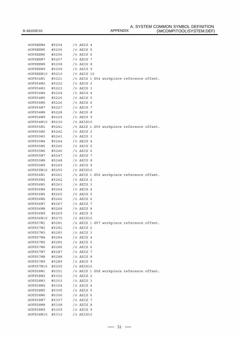
B–66102E/10A. SYSTEM COMMON SYMBOL DEFINITION
(\MCOMP\TOOL\SYSTEM.DEF)APPENDIX
51
@OFSEXW4 #5204 /� AXIS 4
@OFSEXW5 #5205 /� AXIS 5
@OFSEXW6 #5206 /� AXIS 6
@OFSEXW7 #5207 /� AXIS 7
@OFSEXW8 #5208 /� AXIS 8
@OFSEXW9 #5209 /� AXIS 9
@OFSEXW10 #5210 /� AXIS 10
@OFS54W1 #5221 /� AXIS 1 G54 workpiece reference offset.
@OFS54W2 #5222 /� AXIS 2
@OFS54W3 #5223 /� AXIS 3 @OFS54W4 #5224 /� AXIS 4
@OFS54W5 #5225 /� AXIS 5
@OFS54W6 #5226 /� AXIS 6
@OFS54W7 #5227 /� AXIS 7
@OFS54W8 #5228 /� AXIS 8
@OFS54W9 #5229 /� AXIS 9
@OFS54W10 #5230 /� AXIS10
@OFS55W1 #5241 /� AXIS 1 G55 workpiece reference offset.
@OFS55W2 #5242 /� AXIS 2
@OFS55W3 #5243 /� AXIS 3
@OFS55W4 #5244 /� AXIS 4
@OFS55W5 #5245 /� AXIS 5
@OFS55W6 #5246 /� AXIS 6 @OFS55W7 #5247 /� AXIS 7
@OFS55W8 #5248 /� AXIS 8
@OFS55W9 #5249 /� AXIS 9
@OFS55W10 #5250 /� AXIS10
@OFS56W1 #5261 /� AXIS 1 G56 workpiece reference offset.
@OFS56W2 #5262 /� AXIS 2
@OFS56W3 #5263 /� AXIS 3
@OFS56W4 #5264 /� AXIS 4
@OFS56W5 #5265 /� AXIS 5
@OFS56W6 #5266 /� AXIS 6
@OFS56W7 #5267 /� AXIS 7
@OFS56W8 #5268 /� AXIS 8 @OFS56W9 #5269 /� AXIS 9
@OFS56W10 #5270 /� AXIS10
@OFS57W1 #5281 /� AXIS 1 G57 workpiece reference offset.
@OFS57W2 #5282 /� AXIS 2
@OFS57W3 #5283 /� AXIS 3
@OFS57W4 #5284 /� AXIS 4
@OFS57W5 #5285 /� AXIS 5
@OFS57W6 #5286 /� AXIS 6
@OFS57W7 #5287 /� AXIS 7
@OFS57W8 #5288 /� AXIS 8
@OFS57W9 #5289 /� AXIS 9
@OFS57W10 #5290 /� AXIS10
@OFS58W1 #5301 /� AXIS 1 G58 workpiece reference offset. @OFS58W2 #5302 /� AXIS 2
@OFS58W3 #5303 /� AXIS 3
@OFS58W4 #5304 /� AXIS 4
@OFS58W5 #5305 /� AXIS 5
@OFS58W6 #5306 /� AXIS 6
@OFS58W7 #5307 /� AXIS 7
@OFS58W8 #5308 /� AXIS 8
@OFS58W9 #5309 /� AXIS 9
@OFS58W10 #5310 /� AXIS10

A. SYSTEM COMMON SYMBOL DEFINITION (\MCOMP\TOOL\SYSTEM.DEF) B–66102E/10APPENDIX
52
@OFS59W1 #5321 /� AXIS 1 G59 workpiece reference offset.
@OFS59W2 #5322 /� AXIS 2
@OFS59W3 #5323 /� AXIS 3
@OFS59W4 #5324 /� AXIS 4
@OFS59W5 #5325 /� AXIS 5
@OFS59W6 #5326 /� AXIS 6
@OFS59W7 #5327 /� AXIS 7
@OFS59W8 #5328 /� AXIS 8
@OFS59W9 #5329 /� AXIS 9
@OFS59W10 #5330 /� AXIS10/�
/�
/� No.04 OTHER SYMBOL DEFINE.
/� ~~~~~~~~~~~~~~~~~~~~~~~~~~~
@ON =1
@OFF =0
/�
$LIST

B–66102E/10 B. COMPILE ERROR CODE TABLEAPPENDIX
53
B �� ��� ����� ��"� ����
The table below indicates the error codes that may occur in compileprocessing.
Compile Error Codes (1/3)
Error code Meaning
0000 Normal termination
0201 Too many programs
0202 There is no program.
1001 Block delete number contains decimal point.
1002 Block delete number other than 1 to 9 is coded.
1003 Program number is coded not at start of program.
1004 Sequence number is coded not at start of block.
1005 NC statement has format error.
1006 Code other than EOB is present at end of macro statement.
1007 Equal sign cannot be found with macro statement.
1008 DO nesting depth exceeded 3 levels.
1009 Relation operator cannot be found in conditional expression.
100a IF is not followed by GOTO.
100b Closing bracket (]) cannot be found for IF[<conditional-expres-sion>].
100c GOTO n is followed by code other than EOB.
100d DO m is followed by code other than EOB.
100e END m is followed by code other than EOB.
100f Identification number of END does not match DO.
1010 END to match DO cannot be found.
1011 WHILE is not followed by DO.
1012 Closing bracket (]) cannot be found for WHILE[<conditional-ex-pression>].
1013 Block not identifiable as NC statement or macro statement ispresent.
1014 DO to match END cannot be found.
1015 Program number of directory does not match program numberin program.
1016 Program number is missing at start of program.
1017 Error in the IF [...] THEN part
1018 Error in the SETVN statement
1019 Error in DEFADD
101a Error in the POPEN command
101b Error in the PCLOS command
101c Error in the BPRNT command
101d Error in the DPRNT command

B. COMPILE ERROR CODE TABLE B–66102E/10APPENDIX
54
Compile Error Codes (2/3)
Error code Meaning
101e Error in the PGN command
101f Error in the FDEL command
1020 Error in the FOPEN command
1021 Error in the FCLOS command
1022 Error in the FREAD command
1023 Error in the FWRITE command
1024 Error in the FPSET command
1025 Too many IF [...] THEN parts
1027 ”ccall” not followed by EOB code
1028 The multiplicity of IF [...] THEN parts exceeds 3.
1029 AND and OR conditions in the IF [...] part
1030 ”ENDIF” not found for the IF [...] THEN part
1031 More than four ANDs or ORs
1033 The number of ”ELSEs” does not match that of IF [...] THEN parts.
1034 The number of ”ENDIFs” does not match that of IF [...] THENparts.
1035 The number of ”THENs” does not match that of IF [...] THEN parts.
1201 Nesting depth of parentheses exceeded 5 levels.
1202 Closing bracket (]) cannot be found for #[<expression>].
1203 Closing bracket (]) cannot be found for [<expression>].
1204 Second opening bracket ([) cannot be found for ATAN[<expres-sion>]/[<expression>].
1205 Slash (/) cannot be found for ATAN[<expression>]/[<expres-sion>].
1206 First closing bracket (]) cannot be found for ATAN[<expres-sion>]/[<expression>].
1207 Closing bracket (]) cannot be found for function [<expression>].
1208 Format of <expression> contains error.
1209 Format of <expression> on left side of assignment statementcontains error.
120a Format of <expression> in <address>[<expression>], <ad-dress>-[<expression>], or GOTO[<expression>] contains error.
120b Error in the array
1401 Numeric value longer than 8 digits is present.
1402 Decimal point is followed by code other than number.
1403 Macro variable number is longer than 6 digits.
1404 # is not immediately followed by number or opening bracket ([).
1405 Program number is longer than 4 digits.
1406 Sequence number is longer than 4 digits.
1407 Opening bracket ([) cannot be found for function [<expres-sion>].
1408 Opening bracket ([) cannot be found for IF[<expression>] orWHILE[<expression>].
1409 Number m in DO m or END m is longer than 1 digit.

B–66102E/10 B. COMPILE ERROR CODE TABLEAPPENDIX
55
Compile Error Codes (3/3)
Error code Meaning
140a Number m in DO m or END m is not number from 1 to 3.
140b DO or END is followed by code other than number.
140c Alphabetic character string not identifiable as control commandor function are present.
140d Alphabetic character string longer than 5 characters is present.
140e EOR is missing at end of program.
140f Code not usable in program is present.
1410 Character string is longer than 255 characters.
1411 Internal code is longer than 4 characters.
1412 Internal code is not represented in hexadecimal.
1413 Internal code that cannot be represented is specified.
1414 Character string command starting with (* does not end with *).
1415 Pair of parentheses contains unallowable character.
1416 Unusable character found between ”,” and ”;”
1417 Unusable character found between ”@” and ”@”
1418 Error in the ”@” and ”@” specification
1419 Hexadecimal code exceeding two digits
1420 Error in the characters or length of a hexadecimal character string
1421 ’0’ or ’N’ not followed by a digit
1601 Temporary variable area used for executor is insufficient.
NC statement of 1 block includes too many addresses contain-ing <expression>.
1602 GOTO destination is to great. Set jump destination for 4-byteoutput with parameter, or reduce program.
1603 NC statement of 1 block contains more than 50 addresses.
1604 Macro variable number is longer than 6 digits.
1605 Macro variable number is negative.
1606 Macro variable number contains decimal point.
1607 Number after GOTO is longer than 4 digits.
1608 Number after GOTO contains decimal point.
1681 One program contains more than 200 GOTO statements speci-fying sequence numbers directly.
1682 Sequence number for GOTO destination cannot be found.
1683 One program contains more than 100 WHILE statements.
1684 Multiple sequence numbers are present for GOTO destination.
1801 ROM cassette overflowed.
1900 ”%” not found or not correct
2000 Press the RESET button.
2001 Unable to read an NC program
8000 Error in a program number
8001 Unable to convert ASCII codes
9999 missmatch err_code !!

C. ROM WRITE/VERIFICATION PARAMETER TABLE B–66102E/10APPENDIX
56
C �� $����&%����������� ���� ���� ����
Cassette type –K1xx –K2xx –IDxxxx –VCxx –VPxx –Pxx
Series 0 64Kbyte –K110 –K223 –ID40B0 Omitted Omitted Omitted
Series 0 128Kbyte –K110 –K226 –ID50B0 Omitted Omitted Omitted
Series 0 256Kbyte –K110 –K223 –ID40B1 –VCC0 –VP64 –P01
Series 0 512Kbyte –K110 –K223 –ID50B2 –VCC0 –VP64 –P01
Series 0 1M byte –K110 –K223 –ID40B2 –VCC0 –VP64 –P01
Series 15 256Kbyte –K110 –K223 –ID60BD –VCC0 –VP64 –P01
Series 15 512Kbyte –K110 –K223 –ID80BD –VCC0 –VP64 –P01
Series 16A 256Kbyte –K111 –K230 –IDFFF4 Omitted Omitted Omitted
Series 16A 512Kbyte –K111 –K230 –IDFFF3 Omitted Omitted Omitted
Series 16A 1M byte –K111 –K230 –IDFFF2 Omitted Omitted Omitted
Series 16A 2M byte –K111 –K231 –IDFFF1 Omitted Omitted Omitted
Series 18A 128Kbyte –K110 –K230 –IDFFF5 Omitted Omitted Omitted
Series 18A 256Kbyte –K110 –K230 –IDFFF4 Omitted Omitted Omitted
Series 18A 512Kbyte –K110 –K230 –IDFFF3 Omitted Omitted Omitted
Series 18A 1M byte –K110 –K230 –IDFFF2 Omitted Omitted Omitted
Series 18A 2M byte –K110 –K231 –IDFFF1 Omitted Omitted Omitted
Example 1)A Series 0 128K-byte ROM cassette is written to and verified.
A:\> MRO WT SAMPL.ROM –K110 –K226 –ID50B0 –VF
Example 2)A Series 15 512K-byte ROM cassette is written to and verified.
A:\> MROMWT SAMPL.ROM -K110 -K221 -ID80BD -VCC0-VP64 -P01 -VF

B–66102E/10 D. COMPILE/LINK EXAMPLEAPPENDIX
57
D �� ���&��) �*� ��
The compile/link example described below is created under the directory
X:\MCOMP\USR\SAMPL
when the macro compiler utility system is installed.
Details of sample:
Times required for instruction execution by each of the conversationalmacros are measured:
1. #100 = #101+#102 ;
2. #100 = #101 AND #102 ;
3. #100 = SIN[#101] ;
The number of test operations is set beforehand in the common variable(#500). Time required for looping by the number of test operations by theWHILE instruction is measured by the timer variable (#3001). Then timerequired for the same number of loops by the WHILE instructioncontaining an instruction subject to measurement is measured. Thus thedifference between two measurement times is the execution time of theinstruction subject to measurement.
(1) Programs createdFile name = MAIN.SRC Main source program fileFile name = SUB1.SRC Subprogram source file
File name = MAIN.REF Main program reference list fileFile name = MAIN.LST Main program compile list fileFile name = MAIN.REL Main program object fileFile name = SUB1.REF Subprogram reference list fileFile name = SUB1.LST Subprogram compile list fileFile name = SUB1.REL Subprogram object file
(2) Macro liner
File name = SAMPL.LNK Link control fileFile name = SAMPL.MAP Link map list fileFile name = SAMPL.ROM ROM-format file

D. COMPILE/LINK EXAMPLE B–66102E/10APPENDIX
58
Main program source file File name : MAIN.SRC
/�
/� SAMPLE Program.
/�/� Conversation MACRO Execution-Time Test Program.
/� (Vol 01.01 1997.03.14)
/�/�
/� ( MAIN Program )/�
/�
/� Symbol define./�
/� System common symbole FILE Include.
/�$INCLUDE \MCOMP\TOOL\SYSTEM.DEF
/�
/�@LOOPCT #500 /� TEST Loop count.
@TIMESAV #501 /� No-operatinon Time save.@TSTTIME #502 /� Measured Time save.
/�
/�@COUNT #100 /� Loop counter work.
@WORK #100 /� Work regster.
/�/�
>LOOP 100 /� GOTO Sequense No. define.
>FIN 999/�
/�$EJECT
/�
/� No. O1000 : Main program./�
O1000 ;
NUMREAD ; Numeric data input.CURSOR OFF ; Cursol OFF
DISPLAY X0 Y0 B0 (’EXECUTION TIME TEST’) ; ”MENU” display.
X2 Y2 (’1.#101=#102+#103’) ;X2 Y3 (’2.#101=#102 AND #103’);
X2 Y4 (’3.#101=SIN[#102]’) ;;
LOOP DISPLAY X8 Y11 B1 (SELECT TEST NO.) ;
IF [KEYCODE NE INPUT]GOTO FIN ; ”INPUT” key push ?IF [KEYDATA LT 1]GOTO FIN ; 0 < DATA < 3 chk.
IF [KEYDATA GT 3]GOTO FIN ;
; No-ope. Time GET.COUNT = LOOPCT ; Loop counter set.
TIMER1 = 0 ; Timer initialize.
WHILE[COUNT GT 0]DO1 ;COUNT = COUNT -1 ; No-operation loop.
END1 ;
TIMESAV = TIMER1 ; Sample time save.
;
Delete this line in Series15.�

B–66102E/10 D. COMPILE/LINK EXAMPLEAPPENDIX
59
TAIWAP1 = KEYDATA*100+1000 ; Jump To TEST progra.
; O1x00:x=key in data.
;
FIN RETURNP LOOP ; END of conv. MACRO.
/�
/�
$EJECT
/�
/�
/� No. O1001 : Answer display sub program./�
/� LOOPCT : TEST Loop count.
/� TIMESAV : No-operatinon Time.
/� TSTTIME : Measured Time.
/�
O1001 ;
DISPLAY X5 Y4 B0 (SANPLE COUNTER) ; Loop count display.
X20 Y4 FORM 6 ZSUP DATA LOOPCT ;
;
X5 Y6 (TOTAL TIME) ; Total measuer Time
X20 Y6 DATA [TSTTIME-TIMESAV] K1 (MSEC); display.
;WORK = [TSTTIME-TIMESAV] / LOOPCT ; 1 operation Time
X5 Y8 (ONE OPERATION) ; display.
X20 Y8 FORM 5.2 DATA WORK K1 (MSEC) ;
;
RETURN ; Return to main.
/�
/�
%

D. COMPILE/LINK EXAMPLE B–66102E/10APPENDIX
60
Main program reference list file File name : MAIN.REF
Fri Mar-14-1997 16:27:3 Page 1
(F0/F16) Macro Compiler (Pre) V01.01 MAIN.SRC
---------- Compile Parameter -----------------------------------------
---------- Program ---------------------------------------------------
S-Line G-Line
1 /�
2 /� SAMPLE Program.
3 /�
4 /� Conversation MACRO Execution-Time Test Program.
5 /� (Vol 01.01 1997.03.14)6 /�
7 /�
8 /� ( MAIN Program )
9 /�
10 /�
11 /� Symbol define.
12 /�
13 /� System common symbole FILE Include.
14 /�
15 $INCLUDE \MCOMP\TOOL\SYSTEM.DEF
16 $NOLIST
203 /�
204 /�205 @LOOPCT #500 /� TEST Loop count.
206 @TIMESAV #501 /� No-operatinon Time save.
207 @TSTTIME #502 /� Measured Time save.
208 /�
209 /�
210 @COUNT #100 /� Loop counter work.
211 @WORK #100 /� Work regster.
212 /�
213 /�
214 >LOOP 100 /� GOTO Sequense No. define.
215 >FIN 999
216 /�217 /�
218 $EJECT

B–66102E/10 D. COMPILE/LINK EXAMPLEAPPENDIX
61
Fri Mar-14-1997 16:27:3 Page 2
(F0/F16) Macro Compiler (Pre) V01.01 MAIN.SRC
S-Line G-Line
219 /�
220 /� No. O1000 : Main program.
221 /�
222 0001 O1000 ;
223 0002 NUMREAD ;Numeric data input.
224 0003 CURSOR OFF ;Cursol OFF
225 0004 DISPLAY X0 Y0 B0 (’EXECUTION TIME TEST’) ;”MENU” display.
226 0005 X2 Y2 (’1.#101=#102+#103’) ;
227 0006 X2 Y3 (’2.#101=#102 AND #103’);
228 0007 X2 Y4 (’3.#101=SIN[#102]’) ;229 0008 ;
230 0009 LOOP DISPLAY X8 Y11 B1 (SELECT TEST NO.) ;
231 0010 IF [KEYCODE NE INPUT]GOTO FIN ;”INPUT” key push ?
232 0011 IF [KEYDATA LT 1]GOTO FIN ;0 < DATA < 3 chk.
233 0012 IF [KEYDATA GT 3]GOTO FIN ;
234 0013 ;No-ope. Time GET.
235 0014 COUNT = LOOPCT ;Loop counter set.
236 0015 TIMER1 = 0 ;Timer initialize.
237 0016 WHILE[COUNT GT 0]DO1 ;
238 0017 COUNT = COUNT -1 ;No-operation loop.
239 0018 END1 ;
240 0019 TIMESAV = TIMER1 ;Sample time save.
241 0020 ;
242 0021 TAIWAP1 = KEYDATA*100+1000 ;Jump To TEST progra.
243 0022 ;O1x00:x=key in data.
244 0023 ;
245 0024 FIN RETURNP LOOP ;END of conv. MACRO.
246 /�
247 /�
248 $EJECT

D. COMPILE/LINK EXAMPLE B–66102E/10APPENDIX
62
Fri Mar-14-1997 16:27:4 Page 3
(F0/F16) Macro Compiler (Pre) V01.01 MAIN.SRC
S-Line G-Line
249 /�
250 /�
251 /� No. O1001 : Answer display sub program.
252 /�
253 /� LOOPCT : TEST Loop count.254 /� TIMESAV : No-operatinon Time.
255 /� TSTTIME : Measured Time.
256 /�
257 0025 O1001 ;
258 0026 DISPLAY X5 Y4 B0 (SANPLE COUNTER) ;Loop count display.
259 0027 X20 Y4 FORM 6 ZSUP DATA LOOPCT ;
260 0028 ;
261 0029 X5 Y6 (TOTAL TIME) ;Total measuer Time
262 0030 X20 Y6 DATA [TSTTIME-TIMESAV] K1 (MSEC); display.
263 0031 ;
264 0032 WORK = [TSTTIME-TIMESAV] / LOOPCT ;1 operation Time
265 0033 X5 Y8 (ONE OPERATION) ; display.
266 0034 X20 Y8 FORM 5.2 DATA WORK K1 (MSEC) ;
267 0035 ;
268 0036 RETURN ;Return to main.
269 /�
270 /�271 0037 %

B–66102E/10 D. COMPILE/LINK EXAMPLEAPPENDIX
63
Fri Mar-14-1997 16:27:4 Page 4
(F0/F16) Macro Compiler (Pre) V01.01 MAIN.SRC
---------- Cross Reference -------------------------------------------
Symbol Define Line No.
RETURN M99 268
RETURNP M99P 245
DISPLAY G243 225, 230, 258FORM F 259, 266
DATA D 259, 262, 266
ZSUP Z1 259
TAIWAP1 #8500 242
NUMREAD #8502=1 223
KEYCODE #8501 231
INPUT 8 231
KEYDATA #8503 232, 233, 242
CURSOR #8505 224
TIMER1 #3001 236, 240
OFF =0 224
LOOPCT #500 235, 259, 264TIMESAV #501 240, 262, 264
TSTTIME #502 262, 264
COUNT #100 235, 237, 238, 238
WORK #100 264, 266
LOOP 100 230, 245
FIN 999 231, 232, 233, 245

D. COMPILE/LINK EXAMPLE B–66102E/10APPENDIX
64
Main program compile list file File name : MAIN.LST-----------------------------------
14-Mar-1997 16:27:43 Page 1
(F0/F16) Macro Compiler V01.01 MAIN.SRC
---------- Compile Parameter -----------------------------------------
---------- program O1000 ---------------------------------------------
G-Line P-Line
0001 1 O1000;
0002 2 #8502=1;
0003 3 #8505=0;
0004 4 G243X0Y0B0(*0045 0058 0045 0043 0055 0054 0049 004F004E 0020 0054 0049004D 0045 0020 0054 0045 0053 0054*);
0005 5 X2Y2(*0031 002E 0023 0031 0030 0031 003D 0023 0031 0030 0032 002B 00230031 0030 0033*);
0006 6 X2Y3(*0032 002E 0023 0031 0030 0031 003D 0023 0031 0030 0032 0020 0041004E 0044 0020 0023 0031 0030 0033*);
0007 7 X2Y4(*0033 002E 0023 0031 0030 0031 003D 0053 0049 004E 005B 0023 00310030 0032 005D*);
0008 8 ;
0009 9 N100G243X8Y11B1(SELECT TEST NO.);
0010 10 IF[#8501NE8]GOTO999;
0011 11 IF[#8503LT1]GOTO999;
0012 12 IF[#8503GT3]GOTO999;
0013 13 ;
0014 14 #100=#500;0015 15 #3001=0;
0016 16 WHILE[#100GT0]DO1;
0017 17 #100=#100-1;
0018 18 END1;
0019 19 #501=#3001;
0020 20 ;
0021 21 #8500=#8503*100+1000;
0022 22 ;
0023 23 ;
0024 24 N999M99P100;
----------------------------------------------------------------------
0 errors, 24 blocks, 24 total lines
program size = 250 bytes

B–66102E/10 D. COMPILE/LINK EXAMPLEAPPENDIX
65
14-Mar-1997 16:27:46 Page 2
(F0/F16) Macro Compiler V01.01 MAIN.SRC
---------- Cross Reference -------------------------------------------
#100 : 14, 16, 17, 17,
#500 : 14,
#501 : 19,
#3001 : 15, 19,
#8500 : 21,#8501 : 10,
#8502 : 2,
#8503 : 11, 12, 21,
#8505 : 3,
14-Mar-1997 16:27:46 Page 3
(F0/F16) Macro Compiler V01.01 MAIN.SRC
---------- program O1001 ---------------------------------------------
G-Line P-Line
0025 1 O1001;0026 2 G243X5Y4B0(SANPLE COUNTER);
0027 3 X20Y4F6Z1D#500;
0028 4 ;
0029 5 X5Y6(TOTAL TIME);
0030 6 X20Y6D[#502-#501]K1(MSEC);
0031 7 ;
0032 8 #100=[#502-#501]/#500;
0033 9 X5Y8(ONE OPERATION);
0034 10 X20Y8F5.2D#100K1(MSEC);
0035 11 ;
0036 12 M99;
0037 13 %
----------------------------------------------------------------------
0 errors, 13 blocks, 13 total lines
program size = 145 bytes
14-Mar-1997 16:27:47 Page 4
(F0/F16) Macro Compiler V01.01 MAIN.SRC
---------- Cross Reference -------------------------------------------
#100 : 8, 10,#500 : 3, 8,
#501 : 6, 8,
#502 : 6, 8,

D. COMPILE/LINK EXAMPLE B–66102E/10APPENDIX
66
Subprogram source file File name : SUB1.SRC
/�/� SAMPLE Program.
/�
/� Conversation MACRO Execution-Time Test Program./� (Vol 01.01 1997.03.14)
/�/�
/� ( SUB Program )
/�/�
/� Symbol define.
/�/� System common symbole FILE Include.
/�
$INCLUDE \MCOMP\TOOL\SYSTEM.DEF/�
/�@LOOPCT #500 /� TEST Loop count.
@TIMESAV #501 /� No-operatinon Time save.
@TSTTIME #502 /� Measured Time save./�
/�
@COUNT #100 /� Loop counter work.@MAINPR 1000 /� MAIN Program No.
@DISPSUB 1001 /� Answer display SUB Program.
/�/�
>LOOP 100 /� GOTO Sequense No. define.>FIN 999
/�
/�$EJECT
/�
/�/� (#101=#102+#103) Operation Time Test.
/�
/� No. O1100 : SUB program./�
/�O1100 ;
NOREAD ; NO data read.
;DISPLAY X2 Y2 B0 (’#101=#102+#103 TEST’) ; Operation code disp.
;
COUNT = LOOPCT ; Loop counter set.TIMER1 = 0 ; Timer initialize.
WHILE[COUNT GT 0]DO1 ;
#101 = #102 + #103 ; (Time Measure)COUNT = COUNT -1 ;
END1 ;
;TSTTIME = TIMER1 ; Measure Time save.
CALL DISPSUB ; Measure Time disp.

B–66102E/10 D. COMPILE/LINK EXAMPLEAPPENDIX
67
;
LOOP DISPLAY X8 Y11 B1 (PUSH RESET KEY) ;
IF[KEYCODE EQ RESET]GOTO FIN ; ”RESET” key wait.
RETURNP LOOP ;
;
FIN TAIWAP1 = MAINPR ;
RETURN ;
/�
/�
$EJECT/�
/�
/� (#101=#102 AND #103) Operation Time Test.
/�
/� No. O1200 : SUB program.
/�
/�
O1200 ;
NOREAD ; NO data read.
;
DISPLAY X2 Y2 B0 (’#101=#102 AND #103 TEST’); Operation code disp.
;
COUNT = LOOPCT ; Loop counter set.TIMER1 = 0 ; Timer initialize.
WHILE[COUNT GT 0]DO1 ;
#101 = #102 AND #103 ; (Time Measure)
COUNT = COUNT -1 ;
END1 ;
;
TSTTIME = TIMER1 ; Measure Time save.
;
CALL DISPSUB ; Measure Time disp.
;
LOOP DISPLAY X8 Y11 B1 (PUSH RESET KEY) ;
IF[KEYCODE EQ RESET]GOTO FIN ; ”RESET” key wait.RETURNP LOOP ;
;
FIN TAIWAP1 = MAINPR ;
RETURN ;
/�
/�
$EJECT
/�
/�
/� (#101=SIN[#102]) Operation Time Test.
/�
/� No. O1300 : SUB program.
/�/�
O1300 ;
NOREAD ; NO data read.
;
DISPLAY X2 Y2 B0 (’#101=SIN[#102]’) ; Operation code disp.
;
COUNT = LOOPCT ; Loop counter set.
TIMER1 = 0 ; Timer initialize.
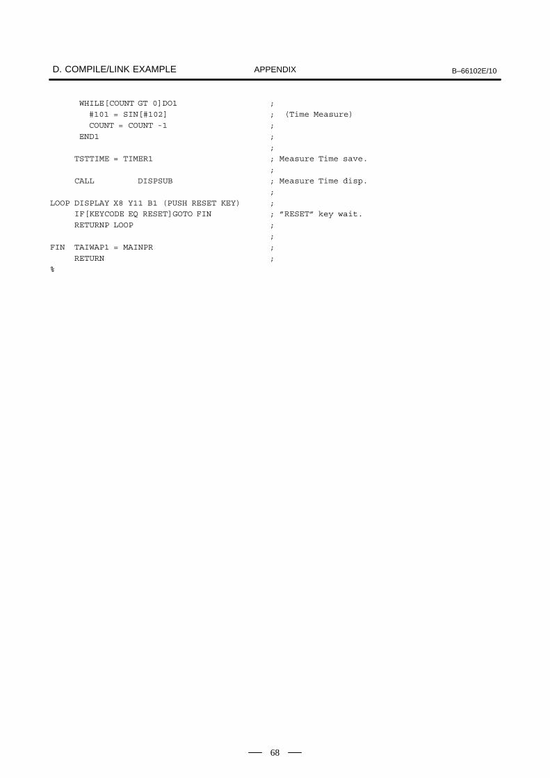
D. COMPILE/LINK EXAMPLE B–66102E/10APPENDIX
68
WHILE[COUNT GT 0]DO1 ;
#101 = SIN[#102] ; (Time Measure)
COUNT = COUNT -1 ;
END1 ;
;
TSTTIME = TIMER1 ; Measure Time save.
;
CALL DISPSUB ; Measure Time disp.
;
LOOP DISPLAY X8 Y11 B1 (PUSH RESET KEY) ;IF[KEYCODE EQ RESET]GOTO FIN ; ”RESET” key wait.
RETURNP LOOP ;
;
FIN TAIWAP1 = MAINPR ;
RETURN ;
%

B–66102E/10 D. COMPILE/LINK EXAMPLEAPPENDIX
69
Subprogram reference list file File name :SUB1.REF--------------------------------------
Fri Mar-14-1997 16:27:4 Page 1
(F0/F16) Macro Compiler (Pre) V01.01 SUB1.SRC
---------- Compile Parameter -----------------------------------------
---------- Program ---------------------------------------------------
S-Line G-Line
1 /�
2 /� SAMPLE Program.
3 /�
4 /� Conversation MACRO Execution-Time Test Program.5 /� (Vol 01.01 1997.03.14)
6 /�
7 /�
8 /� ( SUB Program )
9 /�
10 /�
11 /� Symbol define.
12 /�
13 /� System common symbole FILE Include.
14 /�
15 pINCLUDE \MCOMP\TOOL\SYSTEM.DEF16 pNOLIST
203 /�204 /�
205 @LOOPCT #500 /� TEST Loop count.
206 @TIMESAV #501 /� No-operatinon Time save.
207 @TSTTIME #502 /� Measured Time save.
208 /�
209 /�
210 @COUNT #100 /� Loop counter work.
211 @MAINPR 1000 /� MAIN Program No.
212 @DISPSUB 1001 /� Answer display SUB Program.
213 /�
214 /�
215 >LOOP 100 /� GOTO Sequense No. define.216 >FIN 999
217 /�
218 /�
219 $EJECT

D. COMPILE/LINK EXAMPLE B–66102E/10APPENDIX
70
Fri Mar-14-1997 16:27:4 Page 2
(F0/F16) Macro Compiler (Pre) V01.01 SUB1.SRC
S-Line G-Line
220 /�
221 /�
222 /� (#101=#102+#103) Operation Time Test.
223 /�
224 /� No. O1100 : SUB program.225 /�
226 /�
227 0001 O1100 ;
228 0002 NOREAD ; NO data read.
229 0003 ;
230 0004 DISPLAY X2 Y2 B0 (’#101=#102+#103 TEST’) ; Operation code disp.
231 0005 ;
232 0006 COUNT = LOOPCT ; Loop counter set.
233 0007 TIMER1 = 0 ; Timer initialize.
234 0008 WHILE[COUNT GT 0]DO1 ;
235 0009 #101 = #102 + #103 ; (Time Measure)
236 0010 COUNT = COUNT -1 ;237 0011 END1 ;
238 0012 ;
239 0013 TSTTIME = TIMER1 ; Measure Time save.
240 0014 ;
241 0015 CALL DISPSUB ; Measure Time disp.
242 0016 ;
243 0017 LOOP DISPLAY X8 Y11 B1 (PUSH RESET KEY) ;
244 0018 IF[KEYCODE EQ RESET]GOTO FIN ; ”RESET” key wait.
245 0019 RETURNP LOOP ;
246 0020 ;
247 0021 FIN TAIWAP1 = MAINPR ;
248 0022 RETURN ;249 /�
250 /�
251 $EJECT

B–66102E/10 D. COMPILE/LINK EXAMPLEAPPENDIX
71
Fri Mar-14-1997 16:27:5 Page 3
(F0/F16) Macro Compiler (Pre) V01.01 SUB1.SRC
S-Line G-Line
252 /�
253 /�
254 /� (#101=#102 AND #103) Operation Time Test.
255 /�
256 /� No. O1200 : SUB program.257 /�
258 /�
259 0023 O1200 ;
260 0024 NOREAD ; NO data read.
261 0025 ;
262 0026 DISPLAY X2 Y2 B0 (’#101=#102 AND #103 TEST’); Operation code disp.
263 0027 ;
264 0028 COUNT = LOOPCT ; Loop counter set.
265 0029 TIMER1 = 0 ; Timer initialize.
266 0030 WHILE[COUNT GT 0]DO1 ;
267 0031 #101 = #102 AND #103 ; (Time Measure)
268 0032 COUNT = COUNT -1 ;269 0033 END1 ;
270 0034 ;
271 0035 TSTTIME = TIMER1 ; Measure Time save.
272 0036 ;
273 0037 CALL DISPSUB ; Measure Time disp.
274 0038 ;
275 0039 LOOP DISPLAY X8 Y11 B1 (PUSH RESET KEY) ;
276 0040 IF[KEYCODE EQ RESET]GOTO FIN ; ”RESET” key wait.
277 0041 RETURNP LOOP ;
278 0042 ;
279 0043 FIN TAIWAP1 = MAINPR ;
280 0044 RETURN ;281 /�
282 /�
283 $EJECT
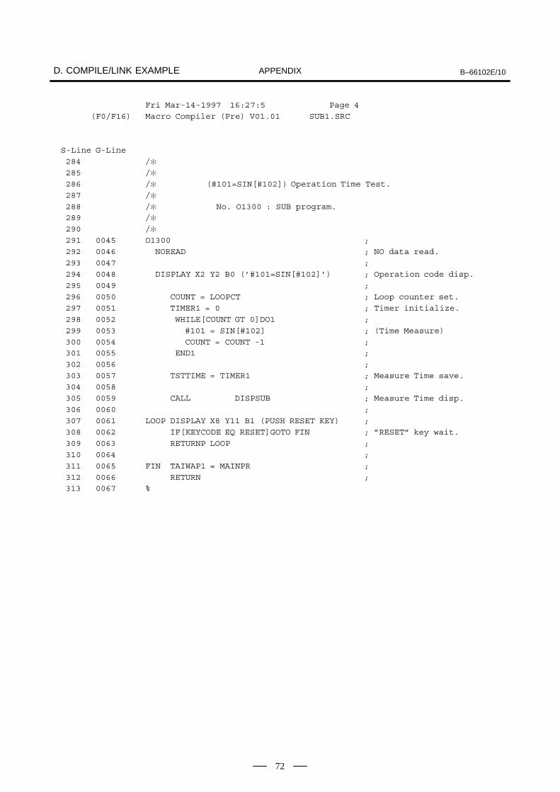
D. COMPILE/LINK EXAMPLE B–66102E/10APPENDIX
72
Fri Mar-14-1997 16:27:5 Page 4
(F0/F16) Macro Compiler (Pre) V01.01 SUB1.SRC
S-Line G-Line
284 /�
285 /�
286 /� (#101=SIN[#102]) Operation Time Test.
287 /�
288 /� No. O1300 : SUB program.289 /�
290 /�
291 0045 O1300 ;
292 0046 NOREAD ; NO data read.
293 0047 ;
294 0048 DISPLAY X2 Y2 B0 (’#101=SIN[#102]’) ; Operation code disp.
295 0049 ;
296 0050 COUNT = LOOPCT ; Loop counter set.
297 0051 TIMER1 = 0 ; Timer initialize.
298 0052 WHILE[COUNT GT 0]DO1 ;
299 0053 #101 = SIN[#102] ; (Time Measure)
300 0054 COUNT = COUNT -1 ;301 0055 END1 ;
302 0056 ;
303 0057 TSTTIME = TIMER1 ; Measure Time save.
304 0058 ;
305 0059 CALL DISPSUB ; Measure Time disp.
306 0060 ;
307 0061 LOOP DISPLAY X8 Y11 B1 (PUSH RESET KEY) ;
308 0062 IF[KEYCODE EQ RESET]GOTO FIN ; ”RESET” key wait.
309 0063 RETURNP LOOP ;
310 0064 ;
311 0065 FIN TAIWAP1 = MAINPR ;
312 0066 RETURN ;313 0067 %

B–66102E/10 D. COMPILE/LINK EXAMPLEAPPENDIX
73
Fri Mar-14-1997 16:27:5 Page 5
(F0/F16) Macro Compiler (Pre) V01.01 SUB1.SRC
---------- Cross Reference -------------------------------------------
Symbol Define Line No.
CALL M98P 241, 273, 305
RETURN M99 248, 280, 312
RETURNP M99P 245, 277, 309DISPLAY G243 230, 243, 262, 275, 294,
307
TAIWAP1 #8500 247, 279, 311
NOREAD #8502=0 228, 260, 292
KEYCODE #8501 244, 276, 308
RESET 10 244, 276, 308
TIMER1 #3001 233, 239, 265, 271, 297,
303
LOOPCT #500 232, 264, 296
TSTTIME #502 239, 271, 303
COUNT #100 232, 234, 236, 236, 264,
266, 268, 268, 296, 298,300, 300
MAINPR 1000 247, 279, 311
DISPSUB 1001 241, 273, 305
LOOP 100 243, 245, 275, 277, 307,
309
FIN 999 244, 247, 276, 279, 308,
311

D. COMPILE/LINK EXAMPLE B–66102E/10APPENDIX
74
Subprogram compile list file File name : SUB1.LST
14-Mar-1997 16:27:57 Page 1
(F0/F16) Macro Compiler V01.01 SUB1.SRC
---------- Compile Parameter -----------------------------------------
---------- program O1100 ---------------------------------------------
G-Line P-Line
0001 1 O1100;
0002 2 #8502=0;
0003 3 ;
0004 4 G243X2Y2B0(*0023 0031 0030 0031 003D 0023 0031 0030 0032 002B 0023 00310030 0033 0020 0054 0045 0053 0054*);
0005 5 ;
0006 6 #100=#500;
0007 7 #3001=0;
0008 8 WHILE[#100GT0]DO1;0009 9 #101=#102+#103;
0010 10 #100=#100-1;
0011 11 END1;
0012 12 ;
0013 13 #502=#3001;
0014 14 ;
0015 15 M98P1001;
0016 16 ;
0017 17 N100G243X8Y11B1(PUSH RESET KEY);
0018 18 IF[#8501EQ10]GOTO999;
0019 19 M99P100;
0020 20 ;0021 21 N999#8500=1000;
0022 22 M99;
----------------------------------------------------------------------
0 errors, 22 blocks, 22 total lines
program size = 163 bytes

B–66102E/10 D. COMPILE/LINK EXAMPLEAPPENDIX
75
---------- Cross Reference -------------------------------------------
#100 : 6, 8, 10, 10,
#101 : 9,
#102 : 9,
#103 : 9,
#500 : 6,
#502 : 13,
#3001 : 7, 13,
#8500 : 21,#8501 : 18,
#8502 : 2,
14-Mar-1997 16:27:59 Page 3
(F0/F16) Macro Compiler V01.01 SUB1.SRC
---------- program O1200 ---------------------------------------------
G-Line P-Line
0023 1 O1200;
0024 2 #8502=0;0025 3 ;
0026 4 G243X2Y2B0(*0023 0031 0030 0031 003D 0023 0031 0030 0032 0020 0041 004E0044 0020 0023 0031 0030 0033 0020 0054 0045 00530054*);
0027 5 ;0028 6 #100=#500;
0029 7 #3001=0;
0030 8 WHILE[#100GT0]DO1;
0031 9 #101=#102AND#103;
0032 10 #100=#100-1;
0033 11 END1;
0034 12 ;
0035 13 #502=#3001;
0036 14 ;
0037 15 M98P1001;
0038 16 ;
0039 17 N100G243X8Y11B1(PUSH RESET KEY);0040 18 IF[#8501EQ10]GOTO999;
0041 19 M99P100;
0042 20 ;
0043 21 N999#8500=1000;
0044 22 M99;
----------------------------------------------------------------------
0 errors, 22 blocks, 22 total lines
program size = 167 bytes

D. COMPILE/LINK EXAMPLE B–66102E/10APPENDIX
76
---------- Cross Reference -------------------------------------------
#100 : 6, 8, 10, 10,
#101 : 9,
#102 : 9,
#103 : 9,
#500 : 6,
#502 : 13,
#3001 : 7, 13,
#8500 : 21,#8501 : 18,
#8502 : 2,
14-Mar-1997 16:28:01 Page 5
(F0/F16) Macro Compiler V01.01 SUB1.SRC
---------- program O1300 ---------------------------------------------
G-Line P-Line
0045 1 O1300;
0046 2 #8502=0;0047 3 ;
0048 4 G243X2Y2B0(*0023 0031 0030 0031 003D 0053 0049 004E 005B 0023 0031 00300032 005D*);
0049 5 ;
0050 6 #100=#500;
0051 7 #3001=0;
0052 8 WHILE[#100GT0]DO1;
0053 9 #101=SIN[#102];
0054 10 #100=#100-1;
0055 11 END1;
0056 12 ;
0057 13 #502=#3001;
0058 14 ;
0059 15 M98P1001;
0060 16 ;0061 17 N100G243X8Y11B1(PUSH RESET KEY);
0062 18 IF[#8501EQ10]GOTO999;
0063 19 M99P100;
0064 20 ;
0065 21 N999#8500=1000;
0066 22 M99;
0067 23 %
----------------------------------------------------------------------
0 errors, 23 blocks, 23 total lines
program size = 156 bytes

B–66102E/10 D. COMPILE/LINK EXAMPLEAPPENDIX
77
---------- Cross Reference -------------------------------------------
#100 : 6, 8, 10, 10,
#101 : 9,
#102 : 9,
#500 : 6,
#502 : 13,
#3001 : 7, 13,
#8500 : 21,
#8501 : 18,#8502 : 2,
Link control file File name : SAMPL.LNK--------------------------------------
/�
/� Conversation MACRO Sample program LINK control file./� ~~~~~~~~~~~~~~~~~~~~~~~~~~~~~~~~~~~~~~~~~~~~~~~~~~~~~~~
/�
/� Library file ’FS0-MC’
/�
CNC=\MCOMP\MEX\F0MC_07.MEX/�
/� compile parameter P9000 - P9009 and P9010 - P9059
/�
P9000=10000010
P9001=00000001
P9002=00100000
P9003=00000001
P9037=5P9038=1000
/�
/� Link file’s
/�
FILE=MAIN
FILE=SUB1
/�

D. COMPILE/LINK EXAMPLE B–66102E/10APPENDIX
78
Link map list file File name : SAMPL.MAP--------------------------------------
Fri Mar-14-1997 16:28:3 Page 1
Macro Linker V01.01SAMPL.MAP
---------- Library List ------------------------------------------------
NO FILE NAME LIBRARY NAME
1 \MCOMP\MEX\F0MC_07.MEX 0-MC MACROLIBRARY
---------- Compile Parameter -------------------------------------------
P9000 = 10000010
P9001 = 00000001
P9002 = 00100000
P9003 = 00000001
P9037 = 5
P9038 = 1000
---------- Object List -------------------------------------------------
FILE NAME PROG SIZE
MAIN.REL 01000 0000FAH
01001 000091H
SUB1.REL 01100 0000A3H
01200 0000A7H
01300 00009CH
---------- ROM FILE SIZE -----------------------------------------------
SIZE = 10000H ( 64KB )

B–66102E/10
E. MACRO CONVERTER (MCONV) OPERATIONGUIDE FOR THE FANUC Series 16/18
Super CAP M/Super CAP II MAPPENDIX
79
E ���� ���%����� � ���%� ��������� ���"� ���
�#� ����� ������ � &�! �+,�� ��� &�+,�� ��� ��

E. MACRO CONVERTER (MCONV) OPERATION GUIDE FOR THE FANUC Series 16/18 Super CAP M/Super CAP II M B–66102E/10APPENDIX
80
Appendix E describes how to operate the tool for supporting theconversational automatic programming function (Super CAP M/SuperCAP II M) for milling machines.
The user can convert conversational programming menu definitionprograms together with other macro programs to ROM-format files in apersonal computer using the procedure below:
The procedures for creating a ROM file and MEM file for Super CAP Mor Super CAP II M are described below.
(1) Create the following menu definition programs with an editor.� Menu definition program� Conversational data definition program� Data item display program
(2) Convert a source file to the table data file in the Super CAP/SuperCAP II M table format using the macro converter (MCONV).Example: MCONV JZH_PARA
JZH_PARA: Name of source program file for table data
(3) Compile the source programs to object files using the macro compiler(MCOMPO).Example: MCOMPO MACHINE
MACHINE: Source program file name
(4) Use the macro linker (MLINK) to convert the object and table datafiles to ROM–format files.Example: MLINK BJ64_J
BJ64_J: Link control file name
(5) Use the MEM file conversion tool (MMCARD) to convertROM–format files to memory–card–format files.This step is not required for the Series 16/18–MA.Example: MMCARD BJ64_J
BJ64_J: ROM–format file name
For the syntax of menu definition programs, refer to the ”Super CAP MProgramming Manual” (B-62153E).
NOTEA FANUC standard macro program is provided only after aconfidentiality agreement with a machine tool builder hasbeen signed.
E.1INTRODUCTION

B–66102E/10
E. MACRO CONVERTER (MCONV) OPERATIONGUIDE FOR THE FANUC Series 16/18
Super CAP M/Super CAP II MAPPENDIX
81
A source file (extension: .DAT) containing a menu definition program,conversational data definition program, and data item display program isconverted to the table data file (extension: .TBL). The conversion resultis output to the table conversion list (extension: .LST).
Menu definition program
Conversational data definition program
Data item display program
(***.DAT)
MCONV Table data
(***.TBL)
Table conversion list
(***.LST)
The command format is as follows:A:\>MCONV file-spec parameters
(1) file-specSpecifies the name of a source file to be converted. Specify a filename in one of the two ways below:� Directly specify a file name or file names
(Examples)A:\>MCONV ABC DEF GHI
This command converts ABC.DAT, DEF.DAT, and GHI.DAT.
� Specify a link control file(Examples)A:\>MCONV @XYZ
This command converts the files specified with TBL= inXYZ.LNK. For details, see Chapter 3.
(2) parametersThe following parameters can be specified.
–NR : Disables table data and files to be output.–L1 : Disables the table conversion list to be output.
Create a source file consisting of menu definition programs in the formatof a text file. Be sure to assign extension .DAT to the source file.
The menu definition program, conversational data definition program,and data item display program can be combined into the file as desired inprogram units. All programs can be created in a single file. If a singlefile contains a single program, up to 488 files can be created.
E.2MACRO CONVERTER(MCONV)
E.2.1Outline
E.2.2Operation
E.2.3Source File

E. MACRO CONVERTER (MCONV) OPERATION GUIDE FOR THE FANUC Series 16/18 Super CAP M/Super CAP II M B–66102E/10APPENDIX
82
This file, which is output by the converter, is to be edited by the macrolinker. The name of the table data file is the same as that of the source filebut with extension .TBL.
Conversion results, such as the list of source programs, error locations,error numbers, and converted file/program numbers, are output to thisfile. The name of the table conversion list file is the same as that of thesource file but with extension .LST.
E.2.4Table Data File
E.2.5Table Conversion ListFile

B–66102E/10
E. MACRO CONVERTER (MCONV) OPERATIONGUIDE FOR THE FANUC Series 16/18
Super CAP M/Super CAP II MAPPENDIX
83
The table data file output by the macro converter can be convertedtogether with the object file output by the macro compiler to ROM-formatfiles with the macro linker.
The following shows an example of specifying a table data file. In theexample, the table data file consists of MENU.TBL for menu definition,DATA.TBL for conversational data, and KOMK.TBL for data itemdisplay.
/� MACRO COMPILER UTILITY LINK FILE/� SYSTEM FILE
CNC=A:\BJ64.PG1
CNC2=A:\BJ64.PG2
CNC3=A:\BJ64.PG3
/� LINK PARAMETER
P9000=11000000
P9001=00000001
P9002=11000000
P9003=10000000
P9007=10000000
P9033=12
P9037=59038=8000
/� MACRO PROGRAM
FILE=ABC,DEF
/� TABLE DATA
TBL=MENU,DATA,KOMK
/�
The link list file to be output by the linker contains a table data file name,program numbers, and program size as well as macro program functions.
The file name is the same as that of the link control file but the extensionis replaced with MAP.
E.3CONVERSION OFTABLE DATA WITHTHE MACRO LINKER(MLINK)
E.3.1Outline
E.3.2Link Control File
E.3.3Link List File

F. CREATING PROGRAMS BY USING SUPER CAP II M/SUPER CAP II T WITH Series 16i/18i B–66102E/10APPENDIX
84
F�������� ������ � �� ����� ����� ��� ��
&����� ��� �� � $��# ������ � i&�!i

B–66102E/10
F. CREATING PROGRAMS BY USING SUPER CAP II M/SUPER CAP II T
WITH Series 16i/18iAPPENDIX
85
The conventional Super CAP system (referred to below as CAP),compiles and links all the required user programs (referred to below asprograms) into a single MEM file (referred to below as a module), thenloads that file into the CNC.
Modular Super CAP (modular CAP) allows programs to be loaded intothe CNC as a set of modules. The modules include a CAP control module,provided as a library, and other program modules.
After the CAP control module has been loaded into the CNC, auser–developed module (user module) can be independently modified orloaded.
NOTEThe modular function can be used with the modular CAPonly.
F.1OVERVIEW

F. CREATING PROGRAMS BY USING SUPER CAP II M/SUPER CAP II T WITH Series 16i/18i B–66102E/10APPENDIX
86
The requirements for developing a user module and operating it on theCNC are listed below:
(1) Personal computer� Main memory: At least 640K bytes� OS: MS–DOS Version 3.1 or above� Hard disk: Minimum of about 20M bytes� 3.5” floppy disk drive
(2) Peripherals� Memory card adapter� 4M–byte flash memory card (Intel iMC004–FLSA)
(3) FAPT macro compiler (for personal computers)� A08B–9001–J760#EN07 (for FANUC Series 16i)� A08B–9001–J765#EN07 (for FANUC Series 18i)
(4) FANUC Super CAP macro library� CAP module� Macro libraries 1 and 2 for developing user modules
(5) NC� NC system supporting modular CAP� Macro capacity of at least 3M bytes� F–ROM module with sufficient capacity to transfer the CAP
control module and user modules
F.2DEVELOPMENTENVIRONMENT
B–66102E/10
F. CREATING PROGRAMS BY USING SUPER CAP II M/SUPER CAP II T
WITH Series 16i/18iAPPENDIX
87
The CAP control module is a MEM file that is provided in place of theconventional library file. The CAP control module is loaded into theCNC.
The CAP control module contains the following programs:
� CAP system control program� FANUC standard macro program (Super CAP II T only)
F.3CAP CONTROLMODULE

F. CREATING PROGRAMS BY USING SUPER CAP II M/SUPER CAP II T WITH Series 16i/18i B–66102E/10APPENDIX
88
The following user modules can be created:
� Up to two user modules (user modules 1 and 2).� The maximum total size of user modules 1 and 2 is 768K bytes
for Super CAP II T and 1.625M bytes for Super CAP II M.The subsequent sections describe the procedure for creating a usermodule, restrictions, and notes.
The following macro libraries are provided for creating the user modules:
� For FANUC Series 16i Super CAP II T: F16ITP1.MEX,F16ITP2.MEX
� For FANUC Series 16i Super CAP II M: F16IMP1.MEX,F16IMP1C.MEX, F16IMP2.MEX
NOTE1 F16?P1.MEX and F16?P1C.MEX are used to create user
module 1.2 F16?P2.MEX is used to create user module 2.
Follow the conventional procedure for developing a user module.Specify a macro library for developing a user module instead of theconventional macro library. Then, compile and link the modules, andconvert the modules into memory card format.
The compile parameters to be specified are the same as the conventionalparameters. When specifying the size of the memory card module,however, specify the size of the user module in the compile parameterindicated below:
Bit No.#7 #6 #5 #4 #3 #2 #1 #0Address
9000 LD6 M3MB M2MB M1MB M512 M256 M128
Do not specify those bits indicated by shading.
Always specify LD6 to 1.
Size M512 M256 M128
512KB 1 0 0
256KB 0 1 0
128KB 0 0 1
The size of user module 1 of Super CAP II M is always 1.375M bytes.Do not specify the M512 bit for user module 2 of Super CAP II M.
Specify the series and edition of the user module by adding the followingtwo lines to the link file.
SERN = seriesVERN = edition
The series and edition can be specified with a combination of up to fourcharacters each from numerals (0 to 9 and upper–case A to Z). The seriesand edition specified in the link file are displayed on the conversationalsystem configuration screen (Super CAP only).
F.4USER MODULES
F.4.1Macro Libraries forDeveloping UserModules
F.4.2Developing a UserModule

B–66102E/10
F. CREATING PROGRAMS BY USING SUPER CAP II M/SUPER CAP II T
WITH Series 16i/18iAPPENDIX
89
NOTESpecify the user module series/edition display.
When a single user program is divided into two modules, specify the samecompile parameters (except parameter 9000) in the link files for usermodules 1 and 2.
User modules 1 and 2 must be loaded into F–ROM separately from theCAP control module.
The CAP control module and user modules 1 and 2 have the following filenames on the F–ROM.
� CAP control module������
Depends on the SYSTEM compile parameter.T when SYSTEM is TPATH1 or TPATH2.M when SYSTEM is MPATH1 or MPATH2.
Depends on the SYSTEM compile parameter.1 when SYSTEM is TPATH1 or MPATH12 when SYSTEM is TPATH2 or MPATH2
� User module 1������
Size specified in compile parameter 9000. However,_CAP is indicated for Super CAP II M.
� User module 2P2����
When a FANUC standard program and a user program have identicalprogram numbers, the user program takes priority. A FANUC standardprogram can, therefore, be changed by creating a new program in the usermodule and assigning it the number of the FANUC standard program tobe changed (Super CAP II T only).
When user modules 1 and 2 have identical program numbers, thatspecified in user module 2 takes priority.
(1) User modules 1 and 2 should not have identical user programnumbers. If the modules have identical program numbers, theprogram specified in user module 2 takes priority.
(2) Identical compile parameters must be specified in user modules 1 and2 (except for compile parameter 9000).
(3) The total size of user modules 1 and 2 must not exceed the following:� Super CAP II T: 768K bytes� Super CAP II M: 1.625M bytes
F.4.3Transferring the UserModule to F–ROM
F.4.4Executing the UserProgram
F.4.5Restrictions and Noteson Developing the UserModule
F. CREATING PROGRAMS BY USING SUPER CAP II M/SUPER CAP II T WITH Series 16i/18i B–66102E/10APPENDIX
90
(1) The P–CODE loading function cannot be used with modular CAP.
(2) No program can be executed with the user modules only. The CAPcontrol module is necessary.
F.5RESTRICTIONSIMPOSED ON THESYSTEM

Character string of the series and edition ofthe user program displayed on the conversa-tional system configuration screen
Character string displayed as the title of the SuperCAP T basic menu screen
B–66102E/10
F. CREATING PROGRAMS BY USING SUPER CAP II M/SUPER CAP II T
WITH Series 16i/18iAPPENDIX
91
� ExampleCreate a 256K–byte user module 1 and link it with the user programsof CAPS and auxiliary processes. Create a 512K–byte user module2 and link it with a user–developed machining macro program.
(1) Edit the string file (CAPS.SRC) to change the title of the Super CAPT basic menu screen and the series and edition of the standard macrodisplayed on the system configuration screen.� Before editing
Several lines omitted/* 123456789012 ;N9998 (’BB0H_ZZ’) ;/* 12345678901234567890123456789012345678901234567890N9999 (’FANUC SUPER CAPIIT!’)Several linesomitted
� After editingSeveral lines omittedN9998 (’ABCDEFG’) ;/* 12345678901234567890123456789012345678901234567890N9999 (’DEBUG SYSTEM FOR SUPER CAP T!’)Several lines omitted
(2) Create user programs for auxiliary processes.� O1004.SRC� O1005.SRC� O1006.SRC
(3) Create a machining macro program.� USR_PRG.SRC
F.6CREATING SAMPLEUSER MODULESFOR SUPER CAP II T
F.6.1Creating Programs

Macro library for user module 1
Add these lines to the link file to display theseries and edition of user module 1.
Specify a size of 256K bytes.
Common part shared by user programs 1and 2
String file: The string file is also included in theSuper CAP control module. A program speci-fied in a user module takes priority.
F. CREATING PROGRAMS BY USING SUPER CAP II M/SUPER CAP II T WITH Series 16i/18i B–66102E/10APPENDIX
92
Create the link files to be used to create user modules 1 and 2.
� Link file for user module 1 (F16ITP1.LNK)/*
/* Conversation MACRO Sample program LINK control file.
/* –––––––––––––––––––––––––––––––––––––––––––––––––––––––
/*
/* executer file ’FS16TI for VGA’
/*
CNC =F16ITP1.MEX
SERN =USR1
VERN =0001
SYSTEM=TPATH1
/*
/* compile parameter P9000 – P9009 and P9010 – P9059
/*
P9000=10000100
P9001=10000001
P9002=11000000
P9003=10001001
P9007=01000000
P9009=00000100
P9013=200
P9021=208
P9022=209
P9023=320
P9024=321
P9030=27
P9031=28
P9033=97
P9037=7
P9044=2044
P9038=4999
/*
/* Link file’s
/*
FILE=CAPS
FILE=O1004
FILE=O1005
FIEL=O1006
F.6.2Creating Link Files

Macro library for user module 2
Add these lines to the link file to display the se-ries and edition of user module 2.
Specify a size of 512K bytes.
Common part shared by user programs 1and 2
B–66102E/10
F. CREATING PROGRAMS BY USING SUPER CAP II M/SUPER CAP II T
WITH Series 16i/18iAPPENDIX
93
� Link file for user module 2 (F16TCP2.LNK)/*
/* Conversation MACRO Sample program LINK control file.
/* –––––––––––––––––––––––––––––––––––––––––––––––––––––––
/*
/* executer file ’FS16TI for VGA’
/*
CNC =F16ITP2.MEX
SERN =USR2
VERN =0001
SYSTEM=TPATH1
/*
/* compile parameter P9000 – P9009 and P9010 – P9059
/*
P9000=10001000
P9001=10000001
P9002=11000000
P9003=10001001
P9007=01000000
P9009=00000100
P9013=200
P9021=208
P9022=209
P9023=320
P9024=321
P9030=27
P9031=28
P9033=97
P9037=7
P9044=2044
P9038=4999
/*
/* Link file’s
/*
FILE=USR_PRG
After creating two files as described above, execute MLINK/MMCARDto create MEM files. The following MEM files are created:
� F16ITP1.MEM: 256K bytes� F16ITP2.MEM: 512K bytes

F. CREATING PROGRAMS BY USING SUPER CAP II M/SUPER CAP II T WITH Series 16i/18i B–66102E/10APPENDIX
94
� ExampleCreate a 1.375M–byte user module 1 and link it with a conversationalmacro program and C program. Create a 256K–byte user module 2and link it with a user–developed auxiliary macro program.
(1) While referring to a FANUC standard macro program, create thefollowing conversational macro programs and conversational macrodefinition tables:� TL_AUTO.SRC� FS_AUTO.SRC� ZH_DATA.SRC� ZH_MENU.SRC� JPN_MENU.TBL� ZH_PARA.TBL
(2) Create a required C program.� CPROG.C
(3) Create an auxiliary macro program.� AUX_PRG.SRC
NOTEA FANUC standard macro program is provided only after aconfidentiality agreement with a machine tool builder hasbeen signed.
F.7CREATING SAMPLEUSER MODULESFOR SUPER CAP II M
F.7.1Creating Programs

Macro library for user module 1.If user module 1 is not linkedwith a C program, useF16IMP1.MEX.
Add these lines to the link file to display the series andedition of user module 1.
The size is always 1.375M bytes and need notbe specified.
Conversational macro program
Conversational macro definition table
C program (when linked)
B–66102E/10
F. CREATING PROGRAMS BY USING SUPER CAP II M/SUPER CAP II T
WITH Series 16i/18iAPPENDIX
95
Create the link files to be used to create user modules 1 and 2.
� Link file for user module 1 (F16IMP1.LNK)/*
/* Conversation MACRO Sample program LINK control file.
/* –––––––––––––––––––––––––––––––––––––––––––––––––––––––
/*
/* executer file ’FS16MI for VGA’
/*
CNC =F16IMP1C.MEX
SERN =USR1
VERN =0001
SYSTEM=MPATH1
/*
/* compile parameter P9000 – P9009 and P9010 – P9059
/v
P9000=10000000
P9001=00000001
P9002=11000000
P9003=10000000
P9007=10000000
P9009=00000010
P9033=12
/*
/* Link file’s
/*
FILE=TL_AUTO
FILE=FS_AUTO
FILE=ZH_DATA
FILE=ZH_MENU
/*
/* Table Data
/*
TBL=JPN_MENU
TBL=ZH_PARA
/*
/* C Program
/*
HFILE=CPROG
F.7.2Creating Link Files

Macro library for user module 2
Add these lines to the link file to display theseries and edition of user module 2.
Specify a size of 256K bytes.
Common part shared by user programs1 and 2
F. CREATING PROGRAMS BY USING SUPER CAP II M/SUPER CAP II T WITH Series 16i/18i B–66102E/10APPENDIX
96
� Link file for user module 2 (F16MCP2.LNK)/*
/* Conversation MACRO Sample program LINK control file.
/* ––––––––––––––––––––––––––––––––––––––––––––––––––––––
/*
/* executer file ’FS16MI for VGA’
/*
CNC =F16IMP2.MEX
SERN =USR2
VERN =0001
SYSTEM=MPATH1
/*
/* compile parameter P9000 – P9009 and P9010 – P9059
/*
P9000=10000100
P9001=00000001
P9002=11000000
P9003=10000000
P9007=10000000
P9009=00000010
P9033=12
/*
/* Link file’s
/*
FILE=AUX_PRG
After creating two files as described above, execute MLINK/MMCARDto create MEM files. The following MEM files are created:
� F16IMP1.MEM: 1.375M bytes� F16IMP2.MEM: 256K bytes

B–66102E/10G. BOOT SYSTEM (FOR Series 16–B/C,
18–B/C, 20, 21–B, 0�–A)APPENDIX
97
G���� ����� ���� ������ � ��&�� �!��&�� ��� �����
�����
G.1 OUTLINE 98. . . . . . . . . . . . . . . . . . . . . . . . . . . . . . . . . . . G.2 OPERATION AND
CORRESPONDING SCREENS 100. . . . . . . . . . . . . . . . G.3 ERROR MESSAGES AND
REQUIRED ACTIONS 115. . . . . . . . . . . . . . . . . . . . . . . . G.4 SETTING A MACRO PASSWORD (Series 20) 118. . . . . G.5 FREE AREA IN FLASH MEMORY (Series 20) 120. . .

G. BOOT SYSTEM (FOR Series 16–B/C, 18–B/C, 20, 21–B, 0�–A) B–66102E/10APPENDIX
98
The boot system of first loads the CNC system software (flash RAM �DRAM), then starts execution of the CNC software so that other softwarecan be executed. (Some models run the CNC system software entirely inflash memory or EPROM, without using DRAM.)
The CNC boot system supports the following system maintenancefunctions:
(1) Registering a file in flash memoryReads a file to flash memory from an MS-DOS format memory cardconforming to JEIDA V4.1.
(2) Checking a file (series and edition) in flash memory
(3) Deleting a file from flash memory
(4) Batch saving of parameters, programs, and other files, powered bybattery (SRAM area), to a memory card and batch restoring of datafrom the memory card
(5) Writing a file in flash memory to a memory card
(6) Formatting a memory card
(7) Deleting a file from a memory cardThis manual describes the activation of the boot system, as well as theoperation and corresponding screen displays for the functions listedabove.
BOOT SYSTEM is automatically started when the CNC is powered on.It then loads and starts the CNC system software. The user, therefore, canusually ignore the operation of BOOT SYSTEM. When maintenance iscarried out or if flash memory does not contain a required file, however,the boot system must be controlled from an on-screen menu.
(1) During system maintenance, for example, when a file in flashmemory is to be replacedOperation: Turn the power on by simultaneously pressing the twosoft keys at the right end.
Hold down the two keys until the boot system screen appears.
(2) If flash memory does not contain a file required to start the CNCIf the file required to start the CNC (NC BASIC) is not found in flashmemory, or if that file is damaged, the BOOT SYSTEM menu isautomatically displayed when the CNC is powered on.
G.1OUTLINE
G.1.1Starting the BOOTSYSTEM

B–66102E/10G. BOOT SYSTEM (FOR Series 16–B/C,
18–B/C, 20, 21–B, 0�–A)APPENDIX
99
The boot system manages files in flash memory by dividing them into twomain groups: system files and user files. These two groups have thefollowing characteristics:
CNC and servo control software provided by FANUC
PMC sequence program (ladder), P-CODE macro program, and otheruser-created files
G.1.2System File and UserFile
� System files
� User files

G. BOOT SYSTEM (FOR Series 16–B/C, 18–B/C, 20, 21–B, 0�–A) B–66102E/10APPENDIX
100
When the boot system is started, the MAIN MENU screen appears. Thecontents of this screen are described below:
� SYSTEM MONITOR MAIN MENU 60M1 - 05
1. SYSTEM DATA LOADING 2. SYSTEM DATA CHECK 3. SYSTEM DATA DELETE 4. SYSTEM DATA SAVE 5. SRAM DATA BACKUP 6. MEMORY CARD FILE DELETE 7. MEMORY CARD FORMAT
10. END ∗∗∗ MESSAGE ∗∗∗ SELECT MODE AND HIT [SELECT] KEY
[ SELECT ][ YES ][ NO ][ UP ][ DOWN ]
�
�
�
�
�
�
�
�: Screen title. The series and edition of the boot system are indicated
at the right end.
�: Function used to write data to flash memory
�: Function used to check the edition of a file in ROM
�: Function used to delete a file from flash memory
�: Function used to make a backup of the data stored on a memory card
: Function used to make a backup of the data in SRAM
�: Function used to delete a file from a memory card
�: Function used to format a memory card
�: Function used to terminate the boot system and start the CNC
: Brief guidance message or error message
Press the [UP] or [DOWN] soft key to select the desired function. Afterpositioning the cursor to the desired function, press the [SELECT] softkey. Before executing a function, the system my request confirmationfrom the operator by having him/her press the [YES] or [NO] soft key.
Position the cursor.
[UP][DOWN]
→
Select a function[SELECT] →
Check the selection
[YES][NO]
→Executethefunction
→ Select END
→ Return to original state
G.2OPERATION ANDCORRESPONDINGSCREENS
� Operating procedure
� Basic operation

B–66102E/10G. BOOT SYSTEM (FOR Series 16–B/C,
18–B/C, 20, 21–B, 0�–A)APPENDIX
101
This screen is used to read a system or user file from a memory card andwrite it to flash memory.
SYSTEM DATA LOADING 1/1FILE DIRECTORYB0A1E01.ROMB0A1E02.ROMEND
∗∗∗ MESSAGE ∗∗∗ SELECT MODE AND HIT SELECT KEY.
[ SELECT ][ YES ][ NO ][ UP ][ DOWN ]
�
�
�
�
�: Screen title. The page number (n) and total number of pages (m) are
displayed in n/m format at the right end.
�: Files on the memory card
�: Option for returning to the previous menu
�: Message
(1) Position the cursor to the file to be read from the memory card intoflash memory. Then, press the [SELECT] soft key.Up to eight file names can be listed on a single page. If nine or morefiles are stored on the memory card, the ninth and subsequent files aredisplayed on other pages. To display the next page, press the [ ] softkey. To display the previous page, press the [ ] soft key. END isdisplayed on the last page.
(2) When a file is selected, the system prompts the operator to confirmloading of that file.
∗∗∗ MESSAGE ∗∗∗LOADING OK ? HIT YES OR NO.
(3) To load the file, press the [YES] soft key. To cancel, press the [NO]key.
∗∗∗ MESSAGE ∗∗∗LOADING FROM MEMORY CARD.
G.2.1System Data LoadingScreen
Description
Screen configuration
Operation

G. BOOT SYSTEM (FOR Series 16–B/C, 18–B/C, 20, 21–B, 0�–A) B–66102E/10APPENDIX
102
(4) When the function terminates normally, the system displays thefollowing message. Press the [SELECT] soft key. If an error occurs,see Appendix (B).
∗∗∗ MESSAGE ∗∗∗LOADING COMPELETE. HIT SELECT KEY.
(a) Counter display while a file is being loadedWhile a file is being loaded, the address of the data currently beingaccessed is displayed.
∗∗∗ MESSAGE ∗∗∗LOADING FROM MEMORY CARD.ADDRESS 001:000022FF
ÃÃÃÃ� �
� The counter is displayed underthe message field.
�: Number of the 128-KB management unit where the data being
accessed is positioned in flash memory
�: Relative address within the management unit (Only series 20 is
indicated.)
(b) File name in flash memoryThe boot system uses the first four characters of the file name toidentify a file in flash memory. If the file to be read from a memorycard and a file already written into flash memory have namesbeginning with the same four characters, delete the latter from flashmemory. Then, start reading the new file into flash memory. Thefollowing table lists the names and contents of files.File names may be changed without notice.
� Series 16/18
File name Contents File type
NC BASIC Basic System file
DG SERVO Servo System file
GRAPHIC Graphic System file
NC OPTN Optional System file
PMC ∗∗∗∗ PMC control software, etc. System file
PCD ∗∗∗∗ P-CODE macro file/OMM User file
CEX ∗∗∗∗ C-language executor User file
PMC-∗∗∗∗ Ladder software User file
PMC@∗∗∗∗ Loader ladder software User file
A square (�) and an asterisk (*) represent a numeric character and analphabetic character respectively.
� Series 20
File name Contents File type
NC BASIC Basic System file
DG SERVO Servo System file
OPT LANG Optional System file
PCD ∗∗∗∗ P-CODE macro file/OMM User file
PMC-∗∗∗∗ Ladder software User file
An asterisk (*) represent a numeric character or an alphabetic characterrespectively.
Others

B–66102E/10G. BOOT SYSTEM (FOR Series 16–B/C,
18–B/C, 20, 21–B, 0�–A)APPENDIX
103
� Series 21
File name Contents File type
NC BASIC Basic (�1) System file
DG SERVO Servo (�1) System file
GRAPHIC Graphic (�1) System file
NC OPTN Optional (�1) System file
PMC ∗∗∗∗ PMC control software, etc. (�1) System file
PCD ∗∗∗∗ P-CODE macro file/OMM User file
PMC-∗∗∗∗ Ladder software User file
PMC@∗∗∗∗ Loader ladder software (�2) User file
A square (�) or an asterisk (*) represent a numeric character or analphabetic character respectively.
(�1) : Only for 21–MB and 21–TB (controller B)
(�2) : Only for 21–TB (controller B)

G. BOOT SYSTEM (FOR Series 16–B/C, 18–B/C, 20, 21–B, 0�–A) B–66102E/10APPENDIX
104
This screen is used to list files in flash memory, together with the numberof 128-KB management units constituting each file and the series andedition of the software.
� SYSTEM DATA CHECKFILE DIRECTORY 1 NC BASIC(10) 2 DG SERVO( 1) 3 PMC-RA ( 1) 4 PCD 0.5M( 4) 5 OPT LANG( 4)END
∗∗∗ MESSAGE ∗∗∗ SELECT FILE AND HIT SELECT KEY.
[ SELECT ][ YES ][ NO ][ UP ][ DOWN ]
�
�
�: Screen title.
�: Names of files in flash memory. The number of management units
constituting each file appears in parentheses to the right of the file
name. The file names are given in item G.2.1–(1).
�: Option for returning to the previous menu
�: Message
�
G.2.2System Data CheckScreen
Description
Screen configuration

B–66102E/10G. BOOT SYSTEM (FOR Series 16–B/C,
18–B/C, 20, 21–B, 0�–A)APPENDIX
105
(1) Select the file for which details are required. For example, select ”1NC BASIC.”
(2) The numbers of management units in the selected file are listed,together with the series and edition of the software. After checkingthe list, press the [SELECT] soft key and return to the file selectionscreen.
ROM FILE CHECKNC BASIC
0 B0A1 801A 000 1 B0A1 802A 001 2 B0A1 841A 002 3 B0A1 842A 003 4 B0A1 881A 004 5 B0A1 882A 005 6 B0A1 8C1A 006 7 B0A1 8C2A 007
∗∗∗ MESSAGE ∗∗∗ HIT SELECT KEY.
Internal management unit number
ROM number and edition
Series
0 B0A1 801A 000
� Parity information for system file and user fileThe NC BASIC, DG SERVO, OPT LANG, and other system files inflash memory contain parity information in each of their managementunits. If the file name field or parity field on the check screen containsa non-ASCII character or @, the flash ROM may bedamaged/destroyed or a damaged file may have been read. Re-readdata from the memory card.The PMC-xxxx, PC-D xxxx, and other user files do not contain parityinformation in each of their management units. A non-ASCIIcharacter or @ may be included in the displayed series/editioninformation. This does not, however, indicate any abnormality.
Operation
Others

G. BOOT SYSTEM (FOR Series 16–B/C, 18–B/C, 20, 21–B, 0�–A) B–66102E/10APPENDIX
106
This screen is used to delete a user file from flash memory.
� SYSTEM DATA DELETEFILE DIRECTORY 1 NC BASIC(10) 2 DG SERVO( 1) 3 PMC-RB ( 1) 4 PCD 0.5M( 4) 5 OPT LANG( 4)END
∗∗∗ MESSAGE ∗∗∗ SELECT FILE AND HIT SELECT KEY.
[ SELECT ][ YES ][ NO ][ UP ][ DOWN ]
�
�
�: Screen title.
�: Names of files in flash memory. The number of management units
constituting each file appears in parentheses to the right of the file
name.
�: Option for returning to the previous menu
�: Message
�
(1) Position the cursor to the name of the file to be deleted. Press the[SELECT] soft key.
(2) The system displays the following confirmation message:
∗∗∗ MESSAGE ∗∗∗DELETE OK ? HIT YES OR NO.
(3) To delete the file, press the [YES] key. To cancel, press the [NO] key.
∗∗∗ MESSAGE ∗∗∗DELETE ROM FILE IN FLASH MEMORY.
(4) When the deletion terminates normally, the system displays thefollowing message. Press the [SELECT] key.
∗∗∗ MESSAGE ∗∗∗DELETE COMPLETE. HIT SELECT KEY.
G.2.3System Data DeleteScreen
Description
Screen configuration
Operation

B–66102E/10G. BOOT SYSTEM (FOR Series 16–B/C,
18–B/C, 20, 21–B, 0�–A)APPENDIX
107
� System file and user file on SYSTEM DATA DELETE screenThe SYSTEM DATA DELETE function provides a safeguard againstaccidental deletion of the system files. User files, however, are notprotected. Protected system files can be overwritten by using theSYSTEM DATA LOADING function.
Others
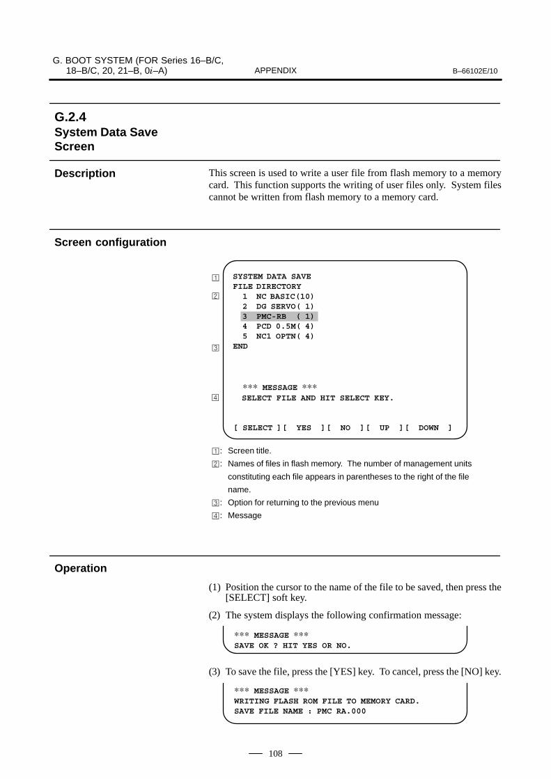
G. BOOT SYSTEM (FOR Series 16–B/C, 18–B/C, 20, 21–B, 0�–A) B–66102E/10APPENDIX
108
This screen is used to write a user file from flash memory to a memorycard. This function supports the writing of user files only. System filescannot be written from flash memory to a memory card.
� SYSTEM DATA SAVEFILE DIRECTORY 1 NC BASIC(10) 2 DG SERVO( 1) 3 PMC-RB ( 1) 4 PCD 0.5M( 4) 5 NC1 OPTN( 4)END
∗∗∗ MESSAGE ∗∗∗ SELECT FILE AND HIT SELECT KEY.
[ SELECT ][ YES ][ NO ][ UP ][ DOWN ]
�
�
�: Screen title.
�: Names of files in flash memory. The number of management units
constituting each file appears in parentheses to the right of the file
name.
�: Option for returning to the previous menu
�: Message
�
(1) Position the cursor to the name of the file to be saved, then press the[SELECT] soft key.
(2) The system displays the following confirmation message:
∗∗∗ MESSAGE ∗∗∗SAVE OK ? HIT YES OR NO.
(3) To save the file, press the [YES] key. To cancel, press the [NO] key.
∗∗∗ MESSAGE ∗∗∗WRITING FLASH ROM FILE TO MEMORY CARD.SAVE FILE NAME : PMC RA.000
G.2.4System Data SaveScreen
Description
Screen configuration
Operation

B–66102E/10G. BOOT SYSTEM (FOR Series 16–B/C,
18–B/C, 20, 21–B, 0�–A)APPENDIX
109
(4) When saving terminates normally, the system displays the followingmessage. Press the [SELECT] key. The name of the file written tothe memory card is displayed. Check the file name.
∗∗∗ MESSAGE ∗∗∗FILE SAVE COMPLETE. HIT SELECT KEY.SAVE FILE NAME : PMC RB.000
(1) Difference between a system file and user file for SYSTEM DATASAVESYSTEM DATA SAVE protects system files so that they cannot becopied easily. User files are not protected.
(2) Names of saved filesThe names of the files written from flash memory to the memory cardare as follows:
� Series 16/18Flash memory Memory card NC BASIC � NC_BASIC.XXXDG SERVO � DG_SERVO.XXXNC1 OPTN � NC1_OPTN.XXXPMC-RB � PMC–RB.XXXPCD 0.5M � PCD_0.5M.XXXPCD 1.0M � PCM_1.0M.XXXPCD 1.5M � PCD_1.5M.XXX
� Series 20Flash memory Memory card NC BASIC � NC_BASIC.XXXDG SERVO � DG_SERVO.XXXOPT LANG � OPT_LANG.XXXPMC-RA � PMC–RA.XXXPCD 0.5M � PCD_0.5M.XXXPCD 1.0M � PCM_1.0M.XXXPCD 1.5M � PCD_1.5M.XXX
� Series 21Flash memory Memory card NC BASIC � NC_BASIC.XXXDG SERVO � DG_SERVO.XXXNC1 OPTN � NC1_OPTN.XXXPMC-RA � PMC–RA.XXXPCD 128k � PCD_128k.XXXPCD 256k � PCD_256k.XXXPCD 0.5M � PCD_0.5M.XXXPCD 1.0M � PCM_1.0M.XXX
XXX is equivalent to the extension assigned to MS-DOS file names.One of 32 numbers from 000 to 031 is assigned as XXX. Forexample, if a PMC-RB file in flash memory is saved to a memory cardcontaining no PMC_RB.* files, the saved file is namedPMC_RB.000. If that same file is saved to a memory card thatalready contains a PMC_RB.000 file, however, it is namedPMC_RB.001. In this way, the extension is incremented by one, upto PMC_RB.031. If there are any free extension numbers in thesequence of the extension numbers, they are used in ascending order.If two or more files having identical names but different extensionnumbers are saved to a single memory card, check the file namesdisplayed after saving. In the case of Serics 20, to write a P-CODEmacro file, with a password assigned by MLINK, from flash memoryto a memory card, the password must be entered. The macropassword is explained in Sec.G.4.
Others

G. BOOT SYSTEM (FOR Series 16–B/C, 18–B/C, 20, 21–B, 0�–A) B–66102E/10APPENDIX
110
This screen is used for the batch saving and restoring of parameters,programs, and other data to be retained after the CNC is turned off to/froma memory card.
Select ”4 SRAM DATA BACKUP” from the SYSTEM MONITORMAIN MENU screen. The following screen is displayed.
� SYSTEM DATA BACKUP
1. SRAM BACKUP ( CNC -> MEMORY CARD ) 2. RESTORE SRAM ( MEMORY CARD -> CNC )END
SRAM SIZE : 512K( BASIC )FILE NAME : SRAM_5A.FDB
∗∗∗ MESSAGE ∗∗∗ SELECT MENU AND HIT SELECT KEY.
[ SELECT ][ YES ][ NO ][ UP ][ DOWN ]
�
�
�
�
�: Screen title.
�: Menu
�: Option for returning to the previous menu
�: Size of SRAM mounted on the CNC
�: File name
: Message
[Backing up data]
(1) Select ”1. SRAM BACKUP.” The following confirmation messageis displayed. To back up the data, press the [YES] key.
∗∗∗ MESSAGE ∗∗∗BACKUP SRAM DATA OK ? HIT YES OR NO.
(2) The FILE NAME: field displays the name of the file that is beingwritten to the memory card. The writing time depends on the amountof free space on the memory card. Generally, to write the SRAMBASIC file (512KB) takes about 2 minutes.
SRAM SIZE : 0.5M( BASIC )FILE NAME : SRAM0_5A.000�MEMORY CARD
∗∗∗ MESSAGE ∗∗∗SRAM DATA WRITING TO MEMORY CARD.
ÃÃÃÃÃÃÃÃÃÃÃÃÃÃÃÃÃÃÃÃÃ
� Name of file that is being backed up.
G.2.5SRAM Data BackupScreen
Description
Screen configuration
Operation
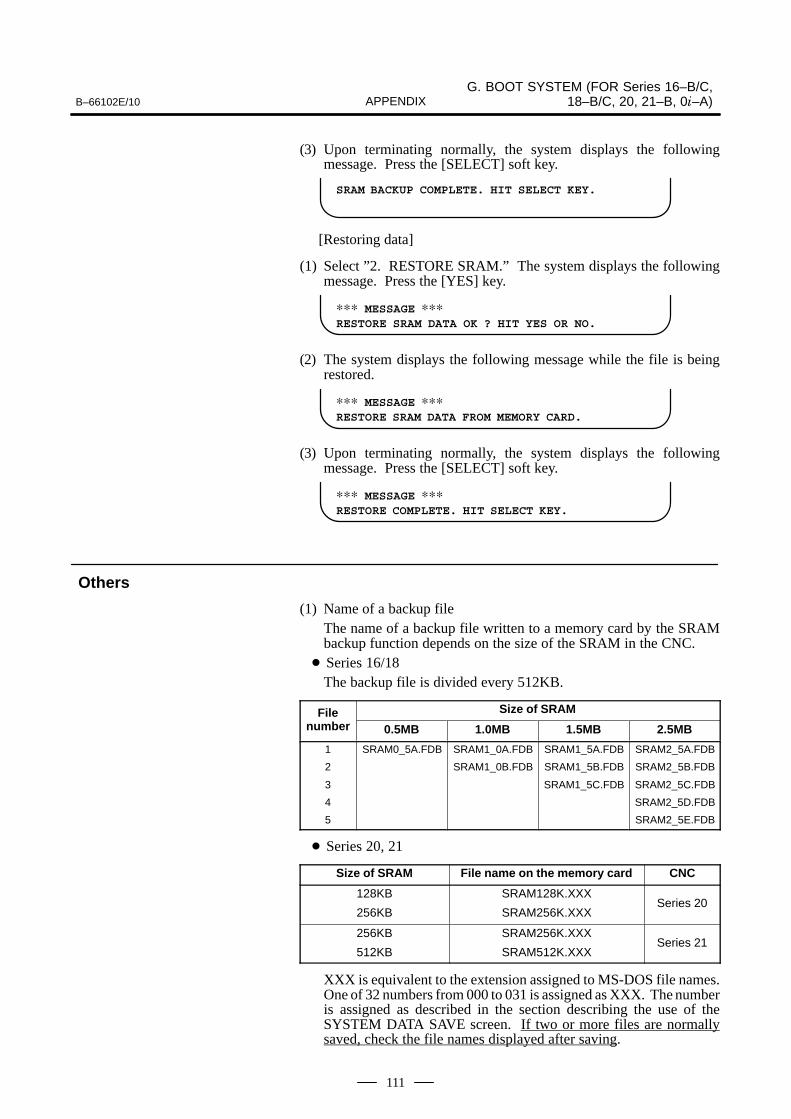
B–66102E/10G. BOOT SYSTEM (FOR Series 16–B/C,
18–B/C, 20, 21–B, 0�–A)APPENDIX
111
(3) Upon terminating normally, the system displays the followingmessage. Press the [SELECT] soft key.
SRAM BACKUP COMPLETE. HIT SELECT KEY.
[Restoring data]
(1) Select ”2. RESTORE SRAM.” The system displays the followingmessage. Press the [YES] key.
∗∗∗ MESSAGE ∗∗∗RESTORE SRAM DATA OK ? HIT YES OR NO.
(2) The system displays the following message while the file is beingrestored.
∗∗∗ MESSAGE ∗∗∗RESTORE SRAM DATA FROM MEMORY CARD.
(3) Upon terminating normally, the system displays the followingmessage. Press the [SELECT] soft key.
∗∗∗ MESSAGE ∗∗∗RESTORE COMPLETE. HIT SELECT KEY.
(1) Name of a backup fileThe name of a backup file written to a memory card by the SRAMbackup function depends on the size of the SRAM in the CNC.
� Series 16/18The backup file is divided every 512KB.
File Size of SRAMFilenumber 0.5MB 1.0MB 1.5MB 2.5MB
1
2
3
4
5
SRAM0_5A.FDB SRAM1_0A.FDB
SRAM1_0B.FDB
SRAM1_5A.FDB
SRAM1_5B.FDB
SRAM1_5C.FDB
SRAM2_5A.FDB
SRAM2_5B.FDB
SRAM2_5C.FDB
SRAM2_5D.FDB
SRAM2_5E.FDB
� Series 20, 21
Size of SRAM File name on the memory card CNC
128KB
256KB
SRAM128K.XXX
SRAM256K.XXXSeries 20
256KB
512KB
SRAM256K.XXX
SRAM512K.XXXSeries 21
XXX is equivalent to the extension assigned to MS-DOS file names.One of 32 numbers from 000 to 031 is assigned as XXX. The numberis assigned as described in the section describing the use of theSYSTEM DATA SAVE screen. If two or more files are normallysaved, check the file names displayed after saving.
Others

G. BOOT SYSTEM (FOR Series 16–B/C, 18–B/C, 20, 21–B, 0�–A) B–66102E/10APPENDIX
112
This screen is used to delete a file from a memory card.
� SYSTEM DATA LOADING 1/1FILE DIRECTORYB0A1E01.ROMB0A1E02.ROM
END
∗∗∗ MESSAGE ∗∗∗ SELECT FILE AND HIT SELECT KEY
[ SELECT ][ YES ][ NO ][ UP ][ DOWN ]
�
�
�: Screen title. The current page number (n) and the total number of
pages (m) are displayed in n/m format at the right-hand end.
�: Files on the memory card
�: Option for returning to the previous menu
�: Message
�
(1) Select the name of the file to be deleted from the memory card bypressing the [SELECT] key.
(2) The system displays the following confirmation message. Press the[YES] key.
∗∗∗ MESSAGE ∗∗∗DELETE OK ? HIT YES OR NO.
(3) Upon normal deletion of the file, the system displays the followingmessage. Press the [SELECT] key.
∗∗∗ MESSAGE ∗∗∗DELETE COMPLETE. HIT SELECT KEY.
� When nine or more files are stored to the memory cardDisplay the desired page, by following the procedure in the sectiondescribing the use of the SYSTEM DATA LOADING screen.
G.2.6Memory Card FileDelete Screen
Description
Screen configuration
Operation
Others

B–66102E/10G. BOOT SYSTEM (FOR Series 16–B/C,
18–B/C, 20, 21–B, 0�–A)APPENDIX
113
This function is used to format a memory card. A memory card must beformatted before it can be used for the first time or before it is to be re-usedafter its data has been lost as a result of its battery failing or similarreasons.
(1) On the SYSTEM MONITOR MAIN MENU screen, select ”7.MEMORY CARD FORMAT.”
(2) The system displays the following confirmation message. Press the[YES] key.
∗∗∗ MESSAGE ∗∗∗MEMORY CARD FORMAT OK ? HIT YES OR NO.
(3) The system displays the following message while formatting amemory card:
∗∗∗ MESSAGE ∗∗∗FORMATTING MEMORY CARD.
(4) Upon the completion of formatting, the system displays the followingmessage. Press the [SELECT] key.
∗∗∗ MESSAGE ∗∗∗FORMAT COMPLETE. HIT SELECT KEY.
G.2.7Memory Card FormatFunction
Description
Operation

G. BOOT SYSTEM (FOR Series 16–B/C, 18–B/C, 20, 21–B, 0�–A) B–66102E/10APPENDIX
114
This function is used to terminate the boot system and activate the CNC.
On the MAIN MENU screen, select ”9. END.” The system displays the”ARE YOU SURE? HIT YES OR NO” message. To terminate the bootsystem and activate the CNC, press the [YES] soft key. If the [NO] keyis pressed, the boot system is not terminated.
∗∗∗ MESSAGE ∗∗∗ARE YOU SURE ? HIT YES OR NO.
[ SELECT ][ YES ][ NO ][ UP ][ DOWN ]
(1) After the [YES] soft key is pressed� The system checks the NC BASIC system file in flash memory. At
this time, the system displays the following message:
∗∗∗ MESSAGE ∗∗∗CHECK CNC BASIC SYSTEM.
[ SELECT ][ YES ][ NO ][ UP ][ DOWN ]
� If the NC BASIC system file is normal, the system reads the systemfile into DRAM (for Series 16-B/C, 18-B/C, or 20) then starts the NCbasic system. During reading, the following message blinks:
∗∗∗ MESSAGE ∗∗∗ LOADING BASIC TO DRAM
[ SELECT ][ YES ][ NO ][ UP ][ DOWN ]
� Upon the completion of loading, the following message appears,after which NC BASIC starts.
∗∗∗ MESSAGE ∗∗∗CNC DATA LOADED
[ SELECT ][ YES ][ NO ][ UP ][ DOWN ]
� If the contents of the NC BASIC system file have been damaged ordestroyed, the system returns to the processing selection screen, inthe same way as when the [NO] soft key is pressed.
(2) If the [NO] soft key is pressed, the system returns to the processingselection screen, shown below:
∗∗∗ MESSAGE ∗∗∗SELECT MENU AND HIT [SELECT] KEY.
[ SELECT ][ YES ][ NO ][ UP ][ DOWN ]
G.2.8End of Boot System
Description
Operation

B–66102E/10G. BOOT SYSTEM (FOR Series 16–B/C,
18–B/C, 20, 21–B, 0�–A)APPENDIX
115
The following table lists and explains error messages in alphabeticalorder.
Message Description and required action
D DELETE ERROR.HIT SELECT KEY.
Cause An attempt to delete a file from flash ROM was unsuccessful.
Action Retry the deletion. If the second attempt also fails, the flashROM may have been damaged or destroyed. Replace theflash ROM module.
DEVICE ERROR (CNC x) Cause An attempt to write data to flash ROM was unsuccessful.
Action Retry the write operation. If the second attempt also fails, theflash ROM may have been damaged or destroyed. Repalcethe flash ROM module.
D–RAM OR S–RAM PARITY Cause Invalid data was found in the RAM area.
Action If an attempt is made to back RAM that has never beencleared, this message appears. When this happens, the bootsystem may stop.
F FILE SAVE ERROR.HIT SELECT KEY.
Cause An attempt to write a file to a memory card was unsuccessful.
Action Check that the memory card is not damaged. (NOTE)
FLASH MEMORY NO SPACE Cause There is insufficient free flash ROM to store the selected file.Delete any unnecessary files from flash ROM.
Action For the Series 20, if this message is displayed and a file can-not be read although the result of calculation indicates thatthe flash memory has enough space, see Section G.5, ”FreeArea of the Flash Memory.”
FLASH ROM MODULE NOT EXIST.HIT SELECT.
Cause The flash ROM module is not mounted on that CNC system.
Action Put the flash ROM module on the board.
FORMAT ERROR. HIT SELECT KEY.
Cause The formatting of the memory card failed.
Action Only a memory card of the SRAM type can be used.Check whether the memory card used is of the flash memorytype.
I ILLEGAL FORMAT FILE Cause The selected file cannot be read into flash memory.
Action The selected file or the header information for flash ROM mayhave been damaged or destroyed.
INCORRECT PASSWORD Cause Error in the password specification
Action Key in the correct password.
L LOADING ERROR.HIT SELECT KEY.
Cause An error occurred while loading data into flash ROM.
Action Do not touch the memory card while loading data.
NOTECheck that the memory card’s battery is not exhusted, thatits circuitry has not been damaged, and that it is securelyinserted into its slot.
G.3ERROR MESSAGESAND REQUIREDACTIONS

G. BOOT SYSTEM (FOR Series 16–B/C, 18–B/C, 20, 21–B, 0�–A) B–66102E/10APPENDIX
116
Message Description and required action
M MAX EXTENSION OVER.HIT SELECT KEY.
Cause The extension number added to a file name exceeds 031.
Action Delete any unnecessary backup files from the memory card.
MEMORY CARD BATTERY ALARM.HIT SELECT.
Cause The memory card’s battery is exhausted.
Action Replace the battery.
MEMORY CARD FULL.HIT SELECT KEY.
Cause The memory card is full.
Action Delete any unnecessary files from the memory card. Alterna-tively, replace the memory card with another card having suffi-cient free space.
MEMORY CARD MOUNT ERROR.HIT SELECT KEY
Cause The memory card could not be accessed.
Action Check that the memory card is normal.
MEMORY CARD NOT EXIST.HIT SELECT KEY.
Cause The memory card is not inserted into its slot.
Action Check that the memory card is pushed fully home.
MEMORY CARD PROTECTED.HITSELECT KEY.
Cause Although writing to the memory card was selected, the writeinhibit switch is set.
Action Disable the write inhibit switch.
MEMORY CARD RESET ERROR.HIT SELECT KEY.
Cause Access to a memory card failed.
Action The memory card’s battery may have gone dead, the memorycard may have been damaged electrically, or the memorycard may not be inserted in the slot securely.
MEMORY CARD WRITE ERROR.HIT SELECT KEY.
Cause Access to the memory card has failed.
Action Check whether the memory card is defective.
N NMI OCCURRED.PLEASE POWER OFF.
Cause A hardware or software error occurred.
Action Determine the procedure which causes the error, and reportit to FANUC together with the series and edition of the bootsoftware.
R ROM PARITY ERROR:NC BASIC. HIT SELECT.
Cause The NC BASIC is parity error.
Action Check whether NC BASIC is in flash ROM, using SYSTEMDATA CHECK.

B–66102E/10G. BOOT SYSTEM (FOR Series 16–B/C,
18–B/C, 20, 21–B, 0�–A)APPENDIX
117
Description and required actionMessage
S SRAM DATA BACKUP ERROR.HIT SELECT KEY.
Cause An attempt to write a backup file to a memory card failed.
Action Check that the memory card is normal.
SRAMXXXX * NOT FOUND.HIT SELECT KEY.
Cause A backup file of the SRAM with a capacity of XXX cannot befound.
Action A backup file is required for restoration.
SRAM PARITY OCCURRED.PLEASE POWER OFF.
Cause A parity error was detected during backup operation of SRAM(Caution).
Action The SRAM areas of all CNCs are cleared before shipmentfrom the factory so that they are free from parity errors. If,however, the CNC receives impact during transportation, orit is left unused for one year or longer, causing the backup bat-tery to run down, a parity error may occur in the SRAM area.If a parity error occurs in the SRAM area, the data stored thereis not guaranteed. On the other hand, the CNC may not usethe entire SRAM area. It is when the portion where a parityerror occurred is called that the error is detected by the hard-ware. If, therefore, a parity error occurs in a portion not ac-cessed by the CNC, the CNC may operate without any prob-lems. The SRAM BACKUP function of BOOT, however,reads the entire SRAM area, and a parity error may be de-tected during backup although the CNC operates without anyproblems. Strictly speaking, if this occurs, the SRAM data ofthe CNC is not guaranteed and the data cannot be backed upusing the SRAM BACKUP function of BOOT. Because, how-ever, the CNC may operate without any problem, it is recom-mended that the necessary data be backed up using a floppycassette or handy file, all data clear be performed, and thenthe data backup be loaded into the CNC. Once all clear is per-formed, the parity error is eliminated, making it possible to usethe SRAM BACKUP function of BOOT.
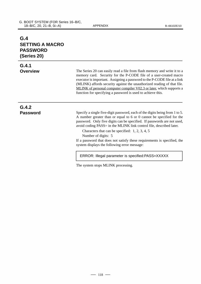
G. BOOT SYSTEM (FOR Series 16–B/C, 18–B/C, 20, 21–B, 0�–A) B–66102E/10APPENDIX
118
The Series 20 can easily read a file from flash memory and write it to amemory card. Security for the P-CODE file of a user-created macroexecutor is important. Assigning a password to the P-CODE file at a link(MLINK) affords security against the unauthorized reading of that file.MLINK of personal computer compiler V02.3 or later, which supports afunction for specifying a password is used to achieve this.
Specify a single five-digit password, each of the digits being from 1 to 5.A number greater than or equal to 6 or 0 cannot be specified for thepassword. Only five digits can be specified. If passwords are not used,avoid coding PASS= in the MLINK link control file, described later.
Characters that can be specified: 1, 2, 3, 4, 5Number of digits: 5
If a password that does not satisfy these requirements is specified, thesystem displays the following error message:
ERROR: Illegal parameter is specified:PASS=XXXXX
The system stops MLINK processing.
G.4SETTING A MACROPASSWORD (Series 20)
G.4.1Overview
G.4.2Password

B–66102E/10G. BOOT SYSTEM (FOR Series 16–B/C,
18–B/C, 20, 21–B, 0�–A)APPENDIX
119
Specify a password in the MLINK link control file (extension .LNK). Thefive digits immediately subsequent to PASS= constitute the password.In the example below, the password is 15243.
/�
/� MACRO COMPILER UTILITY LINK FILE
(SAMPLE)
/�
/�CNC=A:\MCOMP\MEX\F20M.MEX
/�
P9001=0000001
P9010=100
P9037=5P9038=8000
/� JIKKOU-MACRO
FILE=ABC,DEF
FILE=XYZ,UVW
/�FILE=SSS
/� P-CODE FILE PASSWORD
PASS=15243
(Example)
The Series 20 boot system can read a macro executor P-CODE file havingthe password from flash memory only when the password is entered.
INPUT PASSWORD. ?????
The system displays the message and assigns numbers 1 to 5 to the softkeys. When a valid password is entered, the P-CODE file can be writtento a memory card.
1 2 3 4 5
< >
�Soft key indications
�Soft keys
G.4.3Setting a Password
G.4.4Specifying a Passwordfor the Series 20 BootSystem

G. BOOT SYSTEM (FOR Series 16–B/C, 18–B/C, 20, 21–B, 0�–A) B–66102E/10APPENDIX
120
When the NO SPACE message is displayed, flash memory is in one of thefollowing two states:
(1) Flash memory is fully occupied.
(2) Flash memory contains files in non-contiguous areas.In flash memory, only continuous free areas are recognized as free areas.Non-contiguous free areas may be ignored as described in (2) above.
Using the SYSTEM DATA CHECK screen, check the capacity of theflash memory module installed in the Series 20.
Module size Number of management units
2MB 16
3MB 24
4MB 32
Total the number of management units constituting the files in flashmemory and subtract the total from the number of management unitscorresponding to the capacity of the installed flash memory module.
Number of free management units=
Number of management units corresponding – Total number of managementto module capacity unitsconstituting all files
The number of management units constituting each file is given infollowing table.
File name Contents Number of management units
NC BASIC Basic 10
OPT LANG Option 4
DG SERVO Servo 1
PMC-RA Lodder 1
PCD 0.5M P-CODE macro file (0.5M byte) 4
PCD 1.0M P-CODE macro file (1.0M byte) 8
PCD 1.5M P-CODE macro file (1.5M byte) 12
If a NO SPACE error message is displayed even though calculationindicates that flash memory contains sufficient free management units,then the free area in flash memory is non-contiguous. For example, if thefiles are read to a 3MB flash memory module (24 management units) inthe order in which they are listed below, the module will have four freemanagement units.
4
Number of free management units
24
Number of managementunits in the module
20
Total number of management units used
– =
G.5FREE AREA INFLASH MEMORY(Series 20)
G.5.1Determining the Causeof the No–space State

B–66102E/10G. BOOT SYSTEM (FOR Series 16–B/C,
18–B/C, 20, 21–B, 0�–A)APPENDIX
121
1 NC BASIC(10)
2 DG SERVO( 1)
3 PMC-RA ( 1)
4 PCD 0.5M( 4)
5 OPT LANG( 4)
The files are written into the 3MB flash memory module as shown below:
After deletion (non-continuous free areas)Before deletion (continuous free area)
Non-contiguousfree areas
Management unitnumber
000
:
009
010
011
012
013
014
015
016
017
018
019
020
021
022
023
NC BASIC 1
: :
NC BASIC 10
DG SERVO 1
PMC-RA 1
PCD 0.5M 1
PCD 0.5M 2
PCD 0.5M 3
PCD 0.5M 4
OPT LANG 1
OPT LANG 2
OPT LANG 3
OPT LANG 4
Free
Free
Free
Free
File Management unitnumber
000
:
009
010
011
012
013
014
015
016
017
018
019
020
020
020
020
NC BASIC 1
: :
NC BASIC 10
DG SERVO 1
PMC-RA 1
Free
Free
Free
Free
OPT LANG 1
OPT LANG 2
OPT LANG 3
OPT LANG 4
Free
Free
Free
Free
File
If P-CODE macro file PCD 0.5M is deleted, eight management units (1MB)become free in flash memory. As the free management units are separatedin flash memory, the 1-MB P-CODE macro file PCD 1.0M cannot be readinto flash memory. (Use the SYSTEM DATA CHECK screen to determinewhether the management unit numbers of the files are contiguous.)
If non-contiguous free areas are found, use the SYSTEM DATA SAVEfunction to save the OPT LANG file, sandwiched between two free areas,to a memory card. Then, delete the OPT LANG file from flash memory.Re-read the file from the memory card into flash memory. The file willnow be placed next to the PMC-RA file, with a continuous free area of1MB reserved.
NOTEThe OPT LANG system file is deleted in this example onlyfor ease of explanation. Actually, the user cannot delete asystem file.

H. BOOT SYSTEM (FOR Series 16�/18�/21�) B–66102E/10APPENDIX
122
H BOOT SYSTEM (FOR Series 16�/18�/21�)
H.1 OVERVIEW 123. . . . . . . . . . . . . . . . . . . . . . . . . . . . . . . . H.2 SCREEN CONFIGURATION AND OPERATING
PROCEDURE 125. . . . . . . . . . . . . . . . . . . . . . . . . . . . . . H.3 ERROR MESSAGES AND REQUIRED
ACTIONS 140. . . . . . . . . . . . . . . . . . . . . . . . . . . . . . . . . .

B–66102E/10H. BOOT SYSTEM
(FOR Series 16�/18�/21�)APPENDIX
123
The boot system load the CNC system software (flash RAM→DRAM),then starts it so that software can be executed.The boot system provides the following maintenance functions for theCNC:
(1) Registering a file in flash ROM⋅ Reads a file from a memory card, in FAT format, into flash ROM.
(2) Checking a file (series and edition) in flash ROM
(3) Deleting a file from flash ROM
(4) Batch saving and restoration of files of parameters and programsbacked up by battery (SRAM area), to and from a memory card
(5) Saving a file in flash ROM to a memory card
(6) Formatting of a memory card
(7) Deleting a file from a memory cardThis manual describes the activation of the boot system, as well as thescreen displays and operation for the functions listed above.
CAUTIONThis control unit supports the use of a memory card as aninput/output device. When a flash card is used, however,data can be written to a FANUC–recommended card only.Data can be read in the same way as with an ordinary SRAMcard, provided the data has been saved in FAT format. Notethat, when a flash card is used, the card capacity is reducedby 128KB.See the order list for details of the supported memory cardtypes.
In ordinary system activation, the boot system automatically transfersfiles from flash ROM to DRAM in the background.The user is not aware of this operation. However, the boot system mustbe operated manually, from menu screen, when maintenance is to becarried out or when the flash ROM does not contain a required file.
1 In system maintenance, for example, to replace a file in ROMOperation : Turn the power on by simultaneously pressing the two softkeys at the right end.
Hold down the two keys until the boot system screen appears.
If soft keys are not provided (for example, when a touch pad is being
used), use the MDI numeric keys. Hold down the 6 and 7
keys until the boot system screen appears.
�
1.�
2.�
3.�
4.�
5.�
6.�
7.
H.1OVERVIEW
H.1.1Starting the BootSystem

H. BOOT SYSTEM (FOR Series 16�/18�/21�) B–66102E/10APPENDIX
124
2 When the flash memory does not contain a file required to start theCNC
Immediately after the CNC is turned on, the boot system startstransferring files from flash ROM to DRAM. If, for some reason, afile required to start the CNC (NC basic) is not in flash ROM or hasbeen destroyed, the boot system is automatically started.
The boot system organizes files in flash ROM into two main groups :system files and user files. These two file types have the followingcharacteristics :
CNC and servo control software provided by FANUC
PMC sequence program (ladder), P–CODE macro program, and otheruser–created files
When CAP–II board or LCB (loader control board) is mounted on theCNC, we have to access to SRAM that mounted on additional board. So,the boot system displays BOOT SLOT CONFIGURATION screen thatto select a access board.
BOOT SLOT CONFIGURATION 60M1–02
NO. BOARD F–ROM SRAM0. MAIN 4MB 1.0MB1. PMC–RE 6MB 256KB2. CAP–II 512KB3. LCB 512KB
∗∗∗ MESSAGE ∗∗∗SELECT SLOT AND HIT SELECT KEY.[ SELECT ][ YES ][ NO ][ UP ][ DOWN ]
(1)
(2)
(3)
(1) : Screen title.
(2) : Flash memory size and SRAM size of each board.
(3) : Message
Press the [ UP ] or [DOWN] soft key to move the cursor, and select boardto press the [SELECT] soft key.
H.1.2System Files and UserFiles
� System files
� User files
H.1.3Boot SlotConfiguration Screen
� �-���. -/.0�1+�23�/.
� �,��23�/.

B–66102E/10H. BOOT SYSTEM
(FOR Series 16�/18�/21�)APPENDIX
125
When the boot system is first started, the MAIN MENU screen isdisplayed. This screen is described below :
SYSTEM MONITOR MAIN MENU 60M1-01
1. SYSTEM DATA LOADING2. SYSTEM DATA CHECK3. SYSTEM DATA DELETE4. SYSTEM DATA SAVE5. SRAM DATA BACKUP6. MEMORY CARD FILE DELETE7. MEMORY CARD FORMAT
10.END
∗∗∗ MESSAGE ∗∗∗SELECT MENU AND HIT SELECT KEY.[ SELECT ][ YES ][ NO ][ UP ][ DOWN ]
(1)
(2)(3)(4)(5)(6)(7)(8)
(9)
(10)
(1) : Screen title. The series and edition of the boot system appear atthe right end.
(2) : Function for writing data to flash ROM.
(3) : Function for checing the edition of a file in ROM.
(4) : Function for deleting a file from flash ROM.
(5) : Function for making a backup copy of the data stored on the memorycard.
(6) : Function for making a backup copy of the data in SRAM.
(7) : Function for deleting a file from a memory card.
(8) : Function for formatting a memory card.
(9) : Function for terminating the boot system and starting the CNC.
(10):Condensed guidance or error message
Press the [UP] or [DOWN] soft key to select the desired function. Afterpositioning the cursor to the desired function, press the [SELECT] softkey. Before executing a function, the system my request confirmationfrom the operator by having him/her press the [YES] or [NO] soft key.
Position the cursor.
[UP][DOWN]
→
Select a function[SELECT] →
Check the selection
[YES][NO]
→Executethefunction
→ Select END
→ Return to original state
H.2SCREENCONFIGURATIONAND OPERATINGPROCEDURE� ��� ��� �-���.
� Operating procedure
� Basic operation

H. BOOT SYSTEM (FOR Series 16�/18�/21�) B–66102E/10APPENDIX
126
This screen is used to read a system or user file from a memory card intoflash ROM.
SYSTEM DATA LOADING 1/1
FILE DIRECTORYB1F1A_B.MEMB1F1A_AI.MEMEND
∗∗∗ MESSAGE ∗∗∗SELECT FILE AND HIT SELECT KEY.[ SELECT ][ YES ][ NO ][ UP ][ DOWN ]
(1)
(2)
(3)
(4)
(1) : Screen title. The page number (n) and total number of pages (m)are displayed, in n/m format, at the right end.
(2) : Files on the memory card
(3) : Option for returning to previous menu Message
(4) : Message
1 Position the cursor to the file to be read from the memory card andwritten to flash ROM. Then, press the [SELECT] soft key.
A single page can list up to eight file names. If the memory cardcontains nine or more files, the remaining files are displayed onanother page.
To display the next page, press the soft key.
To display the previous page, press the soft key. The END optionis displayed on the last page.
The END option is displayed on the last page.
2 After a file has been slected, the system asks whether that file is to beloaded.
∗∗∗ MESSAGE ∗∗∗LOADING OK ? HIT YES OR NO.
H.2.1System Data LoadingScreen
� Description
� Screen configuration
� Operating procedure

B–66102E/10H. BOOT SYSTEM
(FOR Series 16�/18�/21�)APPENDIX
127
3 To start loading, press the [YES] soft key. To cancel, press the [NO]key.
∗∗∗ MESSAGE ∗∗∗LOADING FROM MEMORY CARD.
4 When loading terminates normally, the system displays the followingmessage. Press the [SELECT] soft key. If an error occurs, see D.3
∗∗∗ MESSAGE ∗∗∗LOADING COMPELETE. HIT SELECT KEY.
1 Counter display while a file is being loaded
While a file is being loaded, the address of the data currently beingaccessed is displayed.
∗∗∗ MESSAGE ∗∗∗LOADING FROM MEMORY CARD.ADDRESS 001: � The counter appears under the
message fild.(1)
(1) : Number of 128–KB management unit in flash ROM
2 File name in flash ROM
The boot system identifies a file in flash ROM by the first fourcharacters of the ID in the header. If flash ROM has a file of the sametype as a file to be read from the memory card, the file in flash ROMis deleted before the file on the memory card is read. The followingtable lists the IDs in the header and the contents. Note that these IDsare subject to change without prior notice.
File name Contents File type
NC BASIC Basic System fileDG SERVO Servo System fileGRAPHIC Graphic System fileNC� OPTN Optional System file
PMC�∗∗∗∗ PMC control software, etc. System file
PD�∗���∗ 1st executor User file
P1�∗���∗ 2nd executor User file
P2�∗���∗ 3rd executor User file
CEX ∗∗∗∗ C–language executor(Except Series 21i)
User file
PMC - ∗∗∗∗ Ladder software User file
PMC@∗∗∗∗ Ladder software for the loader User file
� : A numeric character, * : An alphabetic character
� Others

H. BOOT SYSTEM (FOR Series 16�/18�/21�) B–66102E/10APPENDIX
128
3 File name of the executor system software
The Series 16i/18i/21i–A has separate executor system software forpath 1, path 2, and the loader. All the software is stored in the flashROM of the first path.
Under two–path control with the Series 16–C and the like, a commonexecutor system software file name (PCD1.0M, for example) is usedfor different paths. The Series 16i/18i/21i, however, use separate filenames for different paths.
Accordingly, keyword SYSTEM has been added to the link controlfile of the macro compiler. (See Section 4.2, ”Macro Linker.”)
The following format is used for the file name in the flash ROM.
(1) Format of the file name in the flash ROM
Format
First executor (Standard/SuperCAP)
PD“path-number” “attribute” “size”
M : M seriesT : T seriesL : Loader
1 : First path2 : Second path
Standard : Depends onthe compile parameter
S–CAP : A fixed value is embedded.
Second executor(Super CAP only)
P1“path-number” “attribute” “size”
M : M seriesT : T series
1 : First path2 : Second path
Depends on the com-pile parameter
Third executor(Super CAP only)
P2“path-number” “attribute” “size”
M : M seriesT : T series
1 : First path2 : Second path
Depends on the com-pile parameter
(2) File name types in the flash ROM
F–ROM file name Description
PD1M“size”PD2M“size”
First path of M series (first executor)Second path of M series (first executor)
PD1T“size”PD2T“size”
First path of T series (first executor)Second path of T series (first executor)
PD1L“size” First path of loader
P11M“size”P12M“size”
First path of M series (second executor)Second path of M series (second executor)
P21M“size”P22M“size”
First path of M series (third executor)Second path of M series (third executor)
P11T“size”P12T“size”
First path of T series (second executor)Second path of T series (second executor)
P21T“size”P22T“size”
First path of T series (third executor)Second path of T series (third executor)

B–66102E/10H. BOOT SYSTEM
(FOR Series 16�/18�/21�)APPENDIX
129
This screen is used to list files in flash ROM, together with thecorresponding numbers of 128–KB management units in each file and theseries and edition of the software.
SYSTEM DATA CHECK 1/1[BOARD:MAIN]FILE DIRECTORY (FLASH ROM : 4MB)1 NC BASIC ( 10)2 DG SERVO ( 1)3 PMC0BSC ( 2)4 PMC–RB ( 1)5 PCD 0.5M ( 4)END
∗∗∗ MESSAGE ∗∗∗SELECT FILE AND HIT SELECT KEY.[ SELECT ][ YES ][ NO ][ UP ][ DOWN ]
(1)(2)
(3)
(4)
(5)
(1) : Screen title
(2) : Names of accessing board
(3) : Names of files in flash ROM The number of management unitsconstituting each file appears in parentheses to the right of the filename.
(4) : Returning to the previous menu
(5) : Message
H.2.2System Data CheckScreen
� Description
� Screen configuration

H. BOOT SYSTEM (FOR Series 16�/18�/21�) B–66102E/10APPENDIX
130
1 Select the file whose details are required. For example, select “1 NCBASIC (10).”
2 The numbers of management units in the selected file are listed,together with the series and edition of the software in eachmanagement unit. After checking the listed data, select the[SELECT] soft key to return to the file selection screen.
ROM FILE CHECKNC BASIC
0 B1F1 801A 0001 B1F1 802A 0012 B1F1 841A 0023 B1F1 842A 0034 B1F1 881A 0045 B1F1 882A 0056 B1F1 8C1A 0067 B1F1 8C2A 007
∗∗∗ MESSAGE ∗∗∗HIT SELECT KEY.
ÁÁÁÁÁÁÁÁÁÁÁÁÁÁÁÁÁÁÁÁÁÁÁÁÁÁÁ
Internal management–unitnumberROM number and editionSeries
0 B1F1 801A 000
Parity information for the system file and user file The NC BASIC, DG SERVO, and other system files in flash ROMcontain parity information in each management unit. If the file name fieldor parity field on the check screen contains a non–ASC II character or an“@” , the flash ROM may have been destroyed or a damaged file mayhave been read. Re–read the data from the memory card.The PMC–RB, PCD 0.5M, and other user files do not contain parityinformation in each management unit. A non–ASCII character or an “@”may appear in the series/edition information. In this case, it does notindicate that the file has been damaged.
� Operating procedure
� Others

B–66102E/10H. BOOT SYSTEM
(FOR Series 16�/18�/21�)APPENDIX
131
This screen is used to delete a user file from flash ROM.
SYSTEM DATA CHECK 1/1[BOARD:MAIN]FILE DIRECTORY (FLASH ROM : 4MB)1 NC BASIC ( 10)2 DG SERVO ( 1)3 PMC0BSC ( 2)4 PMC–RB ( 1)5 PCD 0.5M ( 4)END
∗∗∗ MESSAGE ∗∗∗SELECT FILE AND HIT SELECT KEY.[ SELECT ][ YES ][ NO ][ UP ][ DOWN ]
(1)(2)
(3)
(4)
(5)
(1) : Screen title
(2) : Names of accessing board
(3) : Names of files in flash ROM The number of management unitsconstituting each file appears in parentheses to the right of the filename.
(4) : Returning to the previous menu
(5) : Message
1 Position the cursor to the name of the file to be deleted. Press the[SELECT] soft key.
2 The system displays the following confirmation message :
∗∗∗ MESSAGE ∗∗∗DELETE OK ? HIT YES OR NO.
3 To start the deletion, press the [YES] key. To cancel, press [NO].
∗∗∗ MESSAGE ∗∗∗DELETING ROM FILE IN FLASH MEMORY.
4 When deletion terminates normally, the system displays the followingmessage. Press the [SELECT] key.
∗∗∗ MESSAGE ∗∗∗DELETING COMPLETE. HIT SELECT KEY.
H.2.3System Data DeleteScreen
� Description
� Screen configuration
� Operating procedure

H. BOOT SYSTEM (FOR Series 16�/18�/21�) B–66102E/10APPENDIX
132
1 System files and user files on SYSTEM DATA DELETE screen The system files are protected from accidental deletion. User files,however, are not protected. Protected system files can beoverwritten from the SYSTEM DATA LOADING screen.
This screen is used to write a user file in flash ROM to a memory card.Only user files can be saved from flash ROM to a memory card. Systemfiles cannot be saved.
SYSTEM DATA SAVE[BOARD:MAIN]FILE DIRECTORY (FLASH ROM : 4MB)1 NC BASIC ( 10)2 DG SERVO ( 1)3 PMC0BSC ( 2)4 PMC–RB ( 1)5 PCD 0.5M ( 4)END
∗∗∗ MESSAGE ∗∗∗SELECT FILE AND HIT SELECT KEY.[ SELECT ][ YES ][ NO ][ UP ][ DOWN ]
(1)(2)
(3)
(4)
(5)
(1) : Screen title
(2) : Names of accessing board
(3) : Names of files in flash memory The number of management unitsconstituting each file appears in parentheses to the right of the filename.
(4) : Returning to the previous menu
(5) : Message
� Others
H.2.4System Data SaveScreen
� Description
� Screen configuration

B–66102E/10H. BOOT SYSTEM
(FOR Series 16�/18�/21�)APPENDIX
133
1 Position the cursor to the name of the file to be deleted. Press the[SELECT] soft key.
2 The system displays the following confirmation message :
∗∗∗ MESSAGE ∗∗∗SAVE OK ? HIT YES OR NO.
3 To start saving, press the [YES] key. To cancel, press [NO].
∗∗∗ MESSAGE ∗∗∗WRITING FLASH ROM FILE TO MEMORY CARD.SAVE FILE NAME : PMC_RB.000
4 When saving terminates normally, the system displays thefollowing message. Press the [SELECT] key. The names of fileswritten to the memory card are listed. Check the file names by, forexample, making a note of the list.
∗∗∗ MESSAGE ∗∗∗FILE SAVE COMPELETE. HIT SELECT KEY.SAVE FILE NAME : PMC_RB.000
1 System files and user files on SYSTEM DATA SAVE screen
The SYSTEM DATA SAVE function provides a safeguard against freecopying of the system files.
User files, however, are not protected.
2 Names of saved files
Files saved from flash ROM to a memory card have the followingnames :
Flash ROM File name inMemory card
PMC–RBPD1M 0.5P12T 1.0CEX1.0MCEX 2.0M
�
�
�
�
�
PMC_RB. XXXPD1M 05.XXXP12T 10.XXX
CEX_10M.XXXCEX_20M.XXX
XXX corresponds to the file extension of MS–DOS format files. Anumber from 000 to 031 is specified for XXX. For example, if thePMC–RB file in flash ROM is saved to a memory card that does not yetcontain a file whose name begins with “PMC–RB”, the saved file isnamed PMC–RB.000. If, however, that file is saved to a memory card thatalready contains a file named PMC–RB.000, the saved file is namedPMC–RB.001. As files are added, the extension is incremented up to amaximum of PMC–RB.031. Any no–longer used numbers in thesequence of the extension numbers are used in as cending order. If twoor more files having identical names but different extension numbers arenormally saved to the memory card, check the file names displayedsubsequently.
� Operating procedure
� Others

H. BOOT SYSTEM (FOR Series 16�/18�/21�) B–66102E/10APPENDIX
134
This screen is used to collectively save and restore parameters, programs,and other data, retained after the CNC power in SRAM is turned off, toand from a memory card.
Select “4 SRAM DATA BACKUP” on the SYSTEM MONITOR MAINMENU screen. The following screen is displayed.
SRAM DATA BACKUP[BOARD:MAIN]1. SRAM BACKUP (CNC � MEMORY CARD)2. RESTORE SRAM (MEMORY CARD � CNC)END
SRAM SIZE : 256K (BASIC)FILE NAME : SRAM256A. FDB
∗∗∗ MESSAGE ∗∗∗SELECT MENU AND HIT SELECT KEY.[ SELECT ][ YES ][ NO ][ UP ][ DOWN ]
(1)(2)(3)
(4)
(5)(6)
(7)
(1) : Screen title
(2) : Names of accessing board
(3) : Menu
(4) : Returning to the previous menu
(5) : Size of SRAM mounted on the CNC
(6) : File name
(7) : Message
H.2.5SRAM Data BackupScreen
� Description
� Screen configuration

B–66102E/10H. BOOT SYSTEM
(FOR Series 16�/18�/21�)APPENDIX
135
1 Select “1. SRAM BACKUP.” The following confirmation message isdisplayed. The backup file name may be displayed according to theSRAM capacity.
2 Press [YES] to start backup.
∗∗∗ MESSAGE ∗∗∗BACKUP SRAM DATA OK ? HIT YES OR NO.
3 If a backup file is already on the memory card, you will be promptedto confirm whether to permit overwriting.
4 The name of the file being written to the memory card is displayed inthe FILE NAME: field.
SRAM SIZE : 0.5MB (BASIC)FILE NAME : SRAM0_5A.FDB � MEMORY CARD
∗∗∗ MESSAGE ∗∗∗SRAM DATA WRITING TO MEMORY CARD.
Name of the file beingsaved
5 Upon terminating normally, the system displays the followingmessage. Press the [SELECT] soft key.
∗∗∗ MESSAGE ∗∗∗SRAM BACKUP COMPLETE. HIT SELECT KEY.
1 Select “2. RESTORE SRAM.” The system displays the followingmessage. Press the [YES] key.
∗∗∗ MESSAGE ∗∗∗RESTORE SRAM DATA OK ? HIT YES OR NO.
2 The system displays the following message during restoration.
∗∗∗ MESSAGE ∗∗∗RESTORE SRAM DATA FROM MEMORY CARD.
3 Upon terminating normally, the system displays the followingmessage. Press the [SELECT] soft key.
∗∗∗ MESSAGE ∗∗∗RESTORE COMPLETE. HIT SELECT KEY.
� Operating procedure
[Backing up data]
[Restoring the data]

of filesSRAM
size
Number
H. BOOT SYSTEM (FOR Series 16�/18�/21�) B–66102E/10APPENDIX
136
1 Name of backup file
The name of the backup file written to the memory card by the SRAMbackup function depends on the size of the SRAM installed in theCNC.
When the size of SRAM is 1MB or larger, backup files are created inunits of 512 KB.
1 2 3 4 5 6
256KB SRAM256A.FDB
0.5MB SRAM0_5A.FDB
1.0MB SRAM1_0A.FDB SRAM1_0B.FDB
2.0MB SRAM2_0A.FDB SRAM2_0B.FDB SRAM2_0C.FDB SRAM2_0D.FDB
3.0MB SRAM3_0A.FDB SRAM3_0B.FDB SRAM3_0C.FDB SRAM3_0D.FDB SRAM3_0E.FDB SRAM3_0F.FDB
The backup file for SRAM on the PMC–RE, CAPII, or LCB boardwill have the following extension:
Board MAIN PMC–RE CAPII LCB
Extension FDB PMC CAP LCB
CAUTIONIf data such as parameters was restored from a memorycard to SRAM in a system using an absolute pulse coder,set bit 4 (APZ) of parameter No. 1815 to 0, and set thereference point again.
� Others

B–66102E/10H. BOOT SYSTEM
(FOR Series 16�/18�/21�)APPENDIX
137
This screen is used to delete a file from a memory card.
SRAM DATA LOADING 1/1FILE DIRECTORYB1F1A_B.MEMB1F1A_A1.MEMEND
∗∗∗ MESSAGE ∗∗∗SELECT FILE AND HIT SELECT KEY.[ SELECT ][ YES ][ NO ][ UP ][ DOWN ]
(1)
(2)
(3)
(4)
(1) : Screen title. Tlhe current page number (n) and the total numberof pages (m) are displayed, in n/m format, at the right end.
(2) : Files on the memory card
(3) : Option for returning to the previous menu
(4) : Message
1 Press the [SELECT] key to select the name of the file to be deletedfrom the memory card.
2 The system displays the following confirmation message. Press the[YES] key.
∗∗∗ MESSAGE ∗∗∗DELETE OK ? HIT YES OR NO.
3 When a file has been deleted normally, display the following message.Press the [SELECT] key.
∗∗∗ MESSAGE ∗∗∗DELETE COMPLETE. HIT SELECT KEY.
H.2.6Memory Card FileDelete Screen
� Description
� Screen configuration
� Operating procedure

H. BOOT SYSTEM (FOR Series 16�/18�/21�) B–66102E/10APPENDIX
138
This function is used to format a memory card. Memory cards must beformatted before they can be used for the first time or before they can bere–used after their data has been destroyed or lost because of, for example,battery failure.
1 From the SYSTEM MONITOR MAIN MENU screen, select “7.
MEMORY CARD FORMAT.”
2 The system displays the following confirmation message.Press the [YES] key.
∗∗∗ MESSAGE ∗∗∗MEMORY CARD FORMAT OK ? HIT YES OR NO.
3 The system displays the following message during formatting :
∗∗∗ MESSAGE ∗∗∗FORMATTING MEMORY CARD.
4 When a card has been formatted normally, the system display the
� following message.
� Press the [SELECT] key.
∗∗∗ MESSAGE ∗∗∗FORMAT COMPLETE. HIT SELECT KEY.
H.2.7Memory Card FormatFunction
� Description
� Operating procedure

B–66102E/10H. BOOT SYSTEM
(FOR Series 16�/18�/21�)APPENDIX
139
The function is used to terminate the boot system and activate the CNC.
From the MAIN MENU screen, select “9. END.” The system displaysthe “ARE YOU SURE? HIT YES OR NO” message. To terminate theboot system and activate the CNC, press the [YES] soft key. Press the[NO] soft key, and you will be brought back to the main menu.
∗∗∗ MESSAGE ∗∗∗ARE YOU SURE ? HIT YES OR NO.
[ SELECT ][ YES ][ NO ][ UP ][ DOWN ]
1 After pressing the [YES] soft key
The system checks the NC BASIC system file in the flash ROM. Thesystem displays the following message :
∗∗∗ MESSAGE ∗∗∗CHECK CNC BASIC SYSTEM.
[ SELECT ][ YES ][ NO ][ UP ][ DOWN ]
When the NC BASIC system file is found to be normal, the systemsends the system file to DRAM and starts the NC basic system. Duringloading, the system blinks the following message.
∗∗∗ MESSAGE ∗∗∗LOADING BASIC TO DRAM
[ SELECT ][ YES ][ NO ][ UP ][ DOWN ]
If the contents of the NC BASIC SYSTEM file are found to have beendamaged or destroyed, the system returns to the processing selectionstate, in exactly the same way as when the [NO] soft key is pressed.
2 If the [NO] soft key is pressed, the system returns to the processingselection state as shown below :
SYSTEM MONITOR MAIN MENU 60M1-01
1. SYSTEM DATA LOADING2. SYSTEM DATA CHECK3. SYSTEM DATA DELETE4. SYSTEM DATA SAVE5. SRAM DATA BACKUP6. MEMORY CARD FILE DELETE7. MEMORY CARD FORMAT
10.END
∗∗∗ MESSAGE ∗∗∗SELECT MENU AND HIT SELECT KEY.[ SELECT ][ YES ][ NO ][ UP ][ DOWN ]
H.2.8Load Basic SystemFunction
� Description
� Operating procedure

H. BOOT SYSTEM (FOR Series 16�/18�/21�) B–66102E/10APPENDIX
140
The following table lists and explains error messages in alphabeticalorder.
Message Description and required action
B BOOT ROM PARITY.PLEASE POWER OFF.
Cause The contents of flash memory containing boot software wasdestroyed.
Action Replace the CPU card.
C CHANGE MEMORY CARD.AND HIT YES OR NO.
Cause The memory card becomes full in the middle of SRAM backupoperation.
Action Replace the card with a memory card containing enough freespace.
D DELETE ERROR.HIT SELECT KEY.
Cause An attempt to delete a file from flash ROM was unsuccessful.
Action Retry the deletion. If the second attempt also fails, the flashROM may have been damaged or destroyed. Replace theflash ROM module.
DEVICE ERROR (CNC x) Cause An attempt to write data to flash ROM was unsuccessful.
Action Retry the write operation. If the second attempt also fails, theflash ROM may have been damaged or destroyed. Repalcethe flash ROM module.
F FILE SAVE ERROR.HIT SELECT KEY.
Cause An attempt to write a file to a memory card was unsuccessful.
Action Check that the memory card is not damaged.
Note) Check that the memory card’s battery is not exhusted, that itscircuitry has not been damaged, and that it is securely in-serted into its slot.
FLASH MEMORY NO SPACE Cause There is insufficient free flash ROM to store the selected file.
Action Delete any unnecessary files from flash ROM.
FLASH ROM MODULE NOT EXIST.HIT SELECT.
Cause The flash ROM module is not mounted on that CNC system.
Action Put the flash ROM module on the board.
I ILLEGAL FORMAT FILE Cause The selected file cannot be read into flash memory.
Action The selected file or the header information for flash ROM mayhave been damaged or destroyed.
ILLEGAL FROM MODULE.HIT SELECT KEY.
Cause The flash ROM module ID is illegal.
Action Check the drawing No. of the flash ROM module.
ILLEGAL SRAM MODULE.HIT SELECT KEY.
Cause The SRAM module ID is illegal.
Action Check the drawing No. of the SRAM module.
L LOADING ERROR.HIT SELECT KEY.
Cause An error occurred while loading data into flash ROM.
Action Do not touch the memory card while loading data.
H.3ERROR MESSAGESAND REQUIREDACTIONS

B–66102E/10H. BOOT SYSTEM
(FOR Series 16�/18�/21�)APPENDIX
141
Description and required actionMessage
M MAX EXTENSION OVER.HIT SELECT KEY.
Cause The extension number added to a file name exceeds 031.
Action Delete any unnecessary backup files from the memory card.
MEMORY CARD BATTERY ALARM.HIT SELECT.
Cause The memory card’s battery is exhausted.
Action Replace the battery.
MEMORY CARD FULL.HIT SELECT KEY.
Cause The memory card is full.
Action Delete any unnecessary files from the memory card. Alterna-tively, replace the memory card with another card having suffi-cient free space.
MEMORY CARD IS NOTAVAILABLE. HIT SEL.
Cause The use of this memory card is not supported.
Action Use only FANUC–recommended memory cards, as de-scribed in the order list.
MEMORY CARD MOUNT ERROR.HIT SELECT KEY
Cause The memory card could not be accessed.
Action Check that the memory card is normal.
MEMORY CARD NOT EXIST.HIT SELECT KEY.
Cause The memory card is not inserted into its slot.
Action Check that the memory card is pushed fully home.
MEMORY CARD PROTECTED.HITSELECT KEY.
Cause Although writing to the memory card was selected, the writeinhibit switch is set.
Action Disable the write inhibit switch.
Note) Check that the memory card’s battery is not exhusted, that itscircuitry has not been damaged, and that it is securely in-serted into its slot.
MEMORY CARD TYPE IS NOTAVAILABLE.
Cause Write has been attempted to an incompatible flash memorycard.
Action Use only the flash ROM cards recommended by FANUC.Recommended flash ROM cards are listed in the ordering list.
MEMORY CARD RESET ERROR.HIT SELECT KEY.
Cause Access to a memory card failed.
Action The memory card’s battery may have gone dead, the memorycard may have been damaged electrically, or the memorycard may not be inserted in the slot securely.
MEMORY CARD WRITE ERROR.HIT SELECT KEY.
Cause Access to the memory card has failed.
Action Check whether the memory card is defective.
Note) Check that the memory card’s battery is not exhusted, that itscircuitry has not been damaged, and that it is securely in-serted into its slot.
N NMI OCCURRED.PLEASE POWER OFF.
Cause A hardware or software error occurred.
Action Determine the procedure which causes the error, and reportit to FANUC together with the series and edition of the bootsoftware.
P PLEASE FORMAT FLASH TYPECARD.HIT SEL.
Cause It is not possible to delete only specific files from a flash ROMcard, due to the characteristics of the memory used.
Action To delete a file it is necessary to delete all files on the card, byusing the FORMAT function.

H. BOOT SYSTEM (FOR Series 16�/18�/21�) B–66102E/10APPENDIX
142
Description and required actionMessage
R ROM PARITY ERROR:NC BASIC. HIT SELECT.
Cause The NC BASIC is parity error.
Action Check whether NC BASIC is in flash ROM, using SYSTEMDATA CHECK.
S SRAM DATA BACKUP ERROR.HIT SELECT KEY.
Cause An attempt to write a backup file to a memory card failed.
Action Check that the memory card is normal.
Note) Check that the memory card’s battery is not exhusted, that itscircuitry has not been damaged, and that it is securely in-serted into its slot.
SRAM PARITY OCCURRED.PLEASE POWER OFF.
Cause A parity error was detected during backup operation of SRAM(Caution).
Action The SRAM areas of all CNCs are cleared before shipmentfrom the factory so that they are free from parity errors. If,however, the CNC receives impact during transportation, orit is left unused for one year or longer, causing the backup bat-tery to run down, a parity error may occur in the SRAM area.If a parity error occurs in the SRAM area, the data stored thereis not guaranteed. On the other hand, the CNC may not usethe entire SRAM area. It is when the portion where a parityerror occurred is called that the error is detected by the hard-ware. If, therefore, a parity error occurs in a portion not ac-cessed by the CNC, the CNC may operate without any prob-lems. The SRAM BACKUP function of BOOT, however,reads the entire SRAM area, and a parity error may be de-tected during backup although the CNC operates without anyproblems. Strictly speaking, if this occurs, the SRAM data ofthe CNC is not guaranteed and the data cannot be backed upusing the SRAM BACKUP function of BOOT. Because, how-ever, the CNC may operate without any problem, it is recom-mended that the necessary data be backed up using a floppycassette or handy file, all data clear be performed, and thenthe data backup be loaded into the CNC. Once all clear is per-formed, the parity error is eliminated, making it possible to usethe SRAM BACKUP function of BOOT.
B–66102E/10
I. P–CODE LOADER FUNCTION (FOR Series 16–B/C, 18–B/C, 21–TA, Series 16i/18i/21i–A/B)APPENDIX
143
I����"� ��"�� �������� ���� ������ � ��&��
�!��&�� ������ ������ � i&�!�&��i��&��

I. P–CODE LOADER FUNCTION (FOR Series 16–B/C, 18–B/C, 21–TA, Series 16i/18i/21i–A/B) B–66102E/10APPENDIX
144
The P-CODE loader function transfers ROM-format files created by apersonal computer (PC) macro compiler into RAM of CNC. The functionalso supports writing to flash ROM (exclude of Series 21–TA).
The CNC is connected to the PC via the RS-232C interface.
The communication parameters for transferring a ROM-format file(loading) depend on the parameters specified for the CNC. Theparameters must be specified prior to loading.
When the CNC is turned off then back on by simultaneously pressing the
CAN and PROG MDI keys, this function displays the specialized data
transfer screen (loading screen). If Series 16/18–B/C having two–pathcontrol is used, the loading screen is displayed after tool post 1 or 2 isselected from the tool post selection screen. Data can be transferred onlywhen the loading screen is displayed.
Specify data transfer from the PC. For details of the transfer command,see Section 4.3.
While this function is being executed, the CNC power-on sequence ishalted. While the specialized data transfer screen or loading screen isdisplayed, the CNC is disabled. This function requires the executorfunction and reader/punch control function.
I.1OUTLINE

B–66102E/10
I. P–CODE LOADER FUNCTION (FOR Series 16–B/C, 18–B/C, 21–TA, Series 16i/18i/21i–A/B)APPENDIX
145
(4) Loading end screen
(5) Flash ROM transfer screen (exclude of 21–TA)
(6) Flash ROM transfer end screen (exclude of 21–TA)
(1) RAM initialization screen
(2) Loading start screen
(3) Loading screen
(1) The communication parameters for loading depend on the parametersspecified for the CNC. Specify the channel to be used, the baud rate,and any other necessary parameters beforehand.
(2) Turn off the power of the CNC. Connect the CNC to the PC via theRS-232C interface.
(3) Simultaneously pressing the CAN and PROG MDI keys of the CNC
turns the CNC on. Keep these keys held down until the MACROCOMPILER/EXECUTOR P-CODE LOADER title appears on thescreen.
I.2PROCESSING BYP–CODE LOADERFUNCTION
I.2.1Starting the P-codeLoader Function
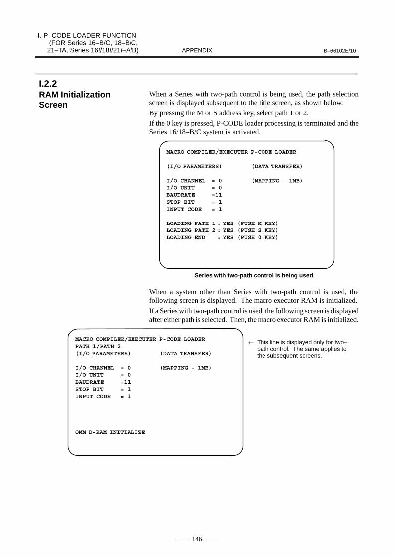
I. P–CODE LOADER FUNCTION (FOR Series 16–B/C, 18–B/C, 21–TA, Series 16i/18i/21i–A/B) B–66102E/10APPENDIX
146
When a Series with two-path control is being used, the path selectionscreen is displayed subsequent to the title screen, as shown below.
By pressing the M or S address key, select path 1 or 2.
If the 0 key is pressed, P-CODE loader processing is terminated and theSeries 16/18–B/C system is activated.
MACRO COMPILER/EXECUTER P-CODE LOADER
(I/O PARAMETERS) (DATA TRANSFER)
I/O CHANNEL = 0 (MAPPING - 1MB)I/O UNIT = 0BAUDRATE =11STOP BIT = 1INPUT CODE = 1
LOADING PATH 1 : YES (PUSH M KEY)LOADING PATH 2 : YES (PUSH S KEY)LOADING END : YES (PUSH 0 KEY)
Series with two-path control is being used
When a system other than Series with two-path control is used, thefollowing screen is displayed. The macro executor RAM is initialized.
If a Series with two-path control is used, the following screen is displayedafter either path is selected. Then, the macro executor RAM is initialized.
MACRO COMPILER/EXECUTER P-CODE LOADER PATH 1/PATH 2(I/O PARAMETERS) (DATA TRANSFER)
I/O CHANNEL = 0 (MAPPING - 1MB)I/O UNIT = 0BAUDRATE =11STOP BIT = 1INPUT CODE = 1
OMM D-RAM INITIALIZE
� This line is displayed only for two–path control. The same applies tothe subsequent screens.
I.2.2RAM InitializationScreen

B–66102E/10
I. P–CODE LOADER FUNCTION (FOR Series 16–B/C, 18–B/C, 21–TA, Series 16i/18i/21i–A/B)APPENDIX
147
After the RAM is initialized, the screen for starting loading is displayed.
MACRO COMPILER/EXECUTER P-CODE LOADER
(I/O PARAMETERS) (DATA TRANSFER)
I/O CHANNEL = 0 (MAPPING - 1MB)I/O UNIT = 0BAUDRATE =11STOP BIT = 1INPUT CODE = 1
LOADING READY ? : YES (PUSH 1 KEY)
Once the PC is ready for data transfer, press the 1 key. The system entersthe loading wait state.
After this screen has been displayed, execute the data transfer commandon the PC, then start data transfer.
MACRO COMPILER/EXECUTER P-CODE LOADER
(I/O PARAMETERS) (DATA TRANSFER)ADR000000H:00
I/O CHANNEL = 0 (MAPPING - 1MB)I/O UNIT = 0BAUDRATE =11STOP BIT = 1INPUT CODE = 1
I.2.3Loading Start Screen

I. P–CODE LOADER FUNCTION (FOR Series 16–B/C, 18–B/C, 21–TA, Series 16i/18i/21i–A/B) B–66102E/10APPENDIX
148
When the CNC receives data, the data reception state is indicated, asshown below.
Under the DATA TRANSFER field, the data being transferred togetherwith its address, are displayed.
For Series except 21–TA, an asterisk ∗ corresponds to about 16K bytesfor DRAM areas of up to 2M bytes or about 32K bytes for DRAM areasof up to 3M bytes. For Series 21-TA, an asterisk ∗ corresponds to about8K bytes.
MACRO COMPILER/EXECUTER P-CODE LOADER
(I/O PARAMETERS) (DATA TRANSFER) ADRxxxxxxH:xx
I/O CHANNEL = 0 (MAPPING - 1MB)
I/O UNIT = 0 ∗∗∗∗BAUDRATE =11STOP BIT = 1INPUT CODE = 1
I.2.4Loading Screen

B–66102E/10
I. P–CODE LOADER FUNCTION (FOR Series 16–B/C, 18–B/C, 21–TA, Series 16i/18i/21i–A/B)APPENDIX
149
This screen indicates whether loading has terminated normally.
(Normal termination)
(1) Except Series 21–TAOnce data has been loaded normally, the following screen appears.
MACRO COMPILER/EXECUTER P-CODE LOADER
(I/O PARAMETERS) (DATA TRANSFER)ADRxxxxxxH:xx
I/O CHANNEL = 0 (MAPPING - 1MB)
I/O UNIT = 0 ∗∗∗∗∗∗∗∗∗∗∗∗∗∗∗BAUDRATE =11 ∗∗∗∗∗STOP BIT = 1INPUT CODE = 1
LOADING END : TOTAL xxxxxxxxBYTESLOADING TO FLASH ROM ? :YES(1)/NO(CAN) YES (PUSH 1 KEY) / NO (PUSH CAN KEY)
YES (PUSH 1 KEY) : Writing to flash ROM is started.NO (PUSH CAN KEY) : The processing is terminated.Specify whether to start writing to the flash ROM.
To start transferring data from RAM to the flash ROM, press the 1 key.(See Subsec. I.2.6.)
If the (CAN) MDI key is pressed, the following screen is displayed.
MACRO COMPILER/EXECUTER P-CODE LOADER
(I/O PARAMETERS) (DATA TRANSFER)ADRxxxxxxH:xx
I/O CHANNEL = 0 (MAPPING - 1MB)
I/O UNIT = 0 ∗∗∗∗∗∗∗∗∗∗∗∗∗∗∗BAUDRATE =11 ∗∗∗∗∗STOP BIT = 1INPUT CODE = 1
PUSH 1 KEY: CNC START WITH EXECUTER
When the 1 key is pressed, the P-CODE loader function is terminated andthe CNC is started.
If a Series with two-path control is being used, the following message isdisplayed.
To return to the path selection screen, press the 1 key.
I.2.5Loading End Screen

I. P–CODE LOADER FUNCTION (FOR Series 16–B/C, 18–B/C, 21–TA, Series 16i/18i/21i–A/B) B–66102E/10APPENDIX
150
MACRO COMPILER/EXECUTER P-CODE LOADER HEAD 1(I/O PARAMETERS) (DATA TRANSFER)
ADRxxxxxxH:xxI/O CHANNEL = 0 (MAPPING - 1MB)
I/O UNIT = 0 ∗∗∗∗∗∗∗∗∗∗∗∗∗∗∗BAUDRATE =11 ∗∗∗∗∗STOP BIT = 1INPUT CODE = 1
PUSH 1 KEY : RETURN TO HEAD SELECTION
(2) For the 21-TAOnce data has been loaded normally, the following screen appears.Pressing the 1 key on this screen causes the P-CODE loaderprocessing to be terminated and the CNC to be started.
MACRO COMPILER/EXECUTER P-CODE LOADER HEAD 1(I/O PARAMETERS) (DATA TRANSFER)
ADRxxxxxxH:xxI/O CHANNEL = 0 (MAPPING - 1MB)
I/O UNIT = 0 ∗∗∗∗∗∗∗∗∗∗∗∗∗∗∗BAUDRATE =11 ∗∗∗∗∗STOP BIT = 1INPUT CODE = 1
PUSH 1 KEY : CNC START WITH EXECUTER
If an error occurs during loading, the following error message isdisplayed.
To retry loading, press the 1 key. (The processing is repeated, startingfrom RAM initialization.)
When you press CAN key and numeric ”1” key on the MDI keyboard, theP-CODE loader processing is terminated and the CNC is started.
If a Series with two-path control is being used, the path selection screenis displayed again.

B–66102E/10
I. P–CODE LOADER FUNCTION (FOR Series 16–B/C, 18–B/C, 21–TA, Series 16i/18i/21i–A/B)APPENDIX
151
(Abnormal termination)
MACRO COMPILER/EXECUTER P-CODE LOADER
(I/O PARAMETERS) (DATA TRANSFER)ADRxxxxxxH:xx
I/O CHANNEL = 0 (MAPPING - 1MB)
I/O UNIT = 0 ∗∗∗∗∗∗∗∗∗∗BAUDRATE =11STOP BIT = 1INPUT CODE = 1
(ERROR OCCURED)ILLEGAL CHARACTER
LOADING RESTART ? : YES (PUSH 1 KEY): NO (PUSH CAN KEY)
YES (PUSH 1 KEY) : Re-loading into RAM is started.NO (PUSH CAN KEY) : The processing is terminated.
Specify whether to start re-loading into RAM.
If the executor or reader/punch control function is not selected, thefollowing message is displayed.
MACRO COMPILER/EXECUTER P-CODE LOADER
(I/O PARAMETERS) (DATA TRANSFER)
I/O CHANNEL = 0 (MAPPING - 1MB)I/O UNIT = 0BAUDRATE =11STOP BIT = 1INPUT CODE = 1
EXECUTER OPTION NOTHINGI/O OPTION NOTHINGI/O OPTION (CH2) NOTHING
PUSH 1 KEY : CNC START
Press the 1 key to terminate the P-CODE loader processing and start theCNC.
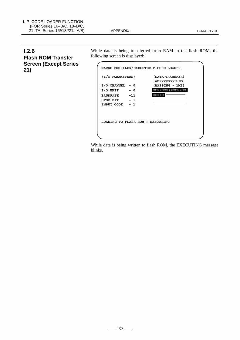
I. P–CODE LOADER FUNCTION (FOR Series 16–B/C, 18–B/C, 21–TA, Series 16i/18i/21i–A/B) B–66102E/10APPENDIX
152
While data is being transferred from RAM to the flash ROM, thefollowing screen is displayed:
MACRO COMPILER/EXECUTER P-CODE LOADER
(I/O PARAMETERS) (DATA TRANSFER)ADRxxxxxxH:xx
I/O CHANNEL = 0 (MAPPING - 1MB)
I/O UNIT = 0 ∗∗∗∗∗∗∗∗∗∗∗∗∗∗∗BAUDRATE =11 ∗∗∗∗∗STOP BIT = 1INPUT CODE = 1
LOADING TO FLASH ROM : EXECUTING
While data is being written to flash ROM, the EXECUTING messageblinks.
I.2.6Flash ROM TransferScreen (Except Series21)

B–66102E/10
I. P–CODE LOADER FUNCTION (FOR Series 16–B/C, 18–B/C, 21–TA, Series 16i/18i/21i–A/B)APPENDIX
153
This screen indicates whether the data transfer to flash ROM terminatednormally.
(Normal termination)
MACRO COMPILER/EXECUTER P-CODE LOADER
(I/O PARAMETERS) (DATA TRANSFER)ADRxxxxxxH:xx
I/O CHANNEL = 0 (MAPPING - 1MB)
I/O UNIT = 0 ∗∗∗∗∗∗∗∗∗∗∗∗∗∗∗BAUDRATE =11 ∗∗∗∗∗STOP BIT = 1INPUT CODE = 1
LOADING TO FLASH ROM : COMPLETEPUSH 1 KEY : CNC START WITH EXECUTER
Press the 1 key to terminate P-CODE processing and start the CNC.
If a Series with two–path control is being used, the following message isdisplayed.
MACRO COMPILER/EXECUTER P-CODE LOADER
(I/O PARAMETERS) (DATA TRANSFER)ADRxxxxxxH:xx
I/O CHANNEL = 0 (MAPPING - 1MB)
I/O UNIT = 0 ∗∗∗∗∗∗∗∗∗∗∗∗∗∗∗BAUDRATE =11 ∗∗∗∗∗STOP BIT = 1INPUT CODE = 1
LOADING TO FLASH ROM : COMPLETEPUSH 1 KEY : RETURN TO HEAD SELECTION
Press the 1 key to return to the path selection screen.
If an attempt to load data into flash ROM fails, the following errormessage is displayed.
To start re-loading into flash ROM, press the 1 key.
Press the CAN key and then 1 key on the MDI keyboard to terminate theP-CODE loader processing and start the CNC. The P-CODE previouslyloaded into DRAM is effective.
If a Series with two-path control is being used, the tool post selectionscreen is displayed again.
I.2.7Flash ROM TransferEnd Screen (ExceptSeries 21)

I. P–CODE LOADER FUNCTION (FOR Series 16–B/C, 18–B/C, 21–TA, Series 16i/18i/21i–A/B) B–66102E/10APPENDIX
154
(Abnormal termination)
MACRO COMPILER/EXECUTER P-CODE LOADER
(I/O PARAMETERS) (DATA TRANSFER)ADRxxxxxxH:xx
I/O CHANNEL = 0 (MAPPING - 1MB)
I/O UNIT = 0 ∗∗∗∗∗∗∗∗∗∗∗∗∗BAUDRATE =11 ∗∗∗∗STOP BIT = 1INPUT CODE = 1
(ERROR OCCURED)UNKNOWN F-ROM MODULE OR NOT MOUNTED
LOADING RESTART ? : YES(PUSH 1 KEY): NO (PUSH CAN KEY)
YES (PUSH 1 KEY) : Re-loading into flash ROM is started.NO (PUSH CAN KEY) : The processing is terminated.
Specify whether to start re-loading into the flash ROM.

B–66102E/10
I. P–CODE LOADER FUNCTION (FOR Series 16–B/C, 18–B/C, 21–TA, Series 16i/18i/21i–A/B)APPENDIX
155
(1) The Series except 21–TA uses either channel 1 or 2 for input andoutput during loading. The Series except 21–TA cannot use anotherchannel for loading. The Series 21-TA use channel 1.
(2) Either ASCII or ISO data can be transferred. EIA data is notsupported.The ASI bit (bit 3 of parameter 101, 111, or 121) specifies whetherASCII or ISO data is being used.
(3) The I/O parameters on the loading screen indicate the values of theRS-232-C parameters related to (1) and (2) above. The parameterscannot be specified using the loading screen.
(4) Even if the PLD bit (bit 1 of parameter 8701) for overwrite loadingis set to 1, the operation of the macro compiler determines whetherboth the P-CODE and executor sections are transferred or if only theP-CODE section is transferred.
(5) When no data is written to the FLASH ROM or data is deleted fromthe FLASH ROM, set the PLD bit (bit 1 of parameter 8701) to 0 sothat the data including the executor section is loaded.
I.2.8Notes

I. P–CODE LOADER FUNCTION (FOR Series 16–B/C, 18–B/C, 21–TA, Series 16i/18i/21i–A/B) B–66102E/10APPENDIX
156
Address
0020 I/O DEVICE SELECTION : I / O C H A N N E L
Setting Entry
[Data type] : Byte[Data range] : 0 to 3Select an I/ O device used.
0 : Select a device connected to channel 1.(I/O device connected to JD5A on MAIN CPU BOARD)
1 : Select a device connected to channel 1.(I/O device connected to JD5A on MAIN CPU BOARD)
2 : Select a device connected to channel 2. (Except Series 21–TA)(I/O device connected to JD5B on MAIN CPU BOARD)
I/O device usable with P- CODE LOADER is either channel 1 or 2.
NOTEThe Series 21-TA use channel 1.
Bit No.#7 #6 #5 #4 #3 #2 #1 #0Address
0101 ASI SB2
[Data type] : BitSB2 : Number of stop bits:
0 : 1 bit 1 : 2 bits
ASI : Input data code: 0 : ISO1 : ASCII
NOTEEIA code cannot be used for P-CODE LOADER.
Address
0102 Specification no. of I/O device (when I/O channel=0)
[Data type] : ByteSet a specification number of I/O device when I/O Channel=0 accordingto Table 1.
�245� 1
Set value Specification of I/O device
0 RS–232–C
1 FANUC CASSETTE ADAPTOR 1 (FANUC CASSETTE B1/B2)
2 FANUC CASSETTE ADAPTOR 3 (FANUC CASSETTE F1)
3 FANUC PROGRAM FILE MateFANUC FA CARD ADAPTORFANUC FLOOPY CASSETTE ADAPTORFANUC SYSTEM P-MODEL H
4 Unused
5 Portable tape reader
6 FANUC PPRFANUC SYSTEM P–MODEL GFANUC SYSTEM P–MODEL H
Set 0 for P-CODE LOADER.
I.3PARAMETER

B–66102E/10
I. P–CODE LOADER FUNCTION (FOR Series 16–B/C, 18–B/C, 21–TA, Series 16i/18i/21i–A/B)APPENDIX
157
Address
0103 Baud rate (For I/O CHANNEL=0)
[Data type] : ByteSet a baud rate of I/O device for I/O CHANNEL=0 according to Table 2.
�245� 2
Set Baud rate Set Baud rate Set Baud rate
1 50 5 20 9 2400
2 100 6 300 10 4800
3 110 7 600 11 9600
4 150 8 1200 12 19200
Set the same baud rate as the personal computer for P-CODE LOADER.Bit No.
#7 #6 #5 #4 #3 #2 #1 #0Address
0111 ASI SB2
[Data type] : BitThese parameters are those for I/O CHANNEL=1. Meaning of each bitis the same as parameter No. 0101.
Address
0112 Specification number of I/O device (for I/O CHANNEL=1)
[Data type] : ByteSet specification number of I/O device when I/O CHANNEL=1according to Table 1.
Address
0113 Baud rate (I/O CHANNEL=1 )
[Data type] : ByteBaud rate of I/O device when I/O CHANNEL=1 according to Table 2.
Bit No.#7 #6 #5 #4 #3 #2 #1 #0Address
0121 ASI SB2
[Data type] : BitThese parameters are those for I/O CHANNEL=2. The meaning of eachbit is the same as parameter No. 101.
Address
0122 Specification number of I/O device (I/O CHANNEL=2)
[Data type] : ByteSet the specification number of I/O device for I/O CHANNEL=2according to Table 1.

I. P–CODE LOADER FUNCTION (FOR Series 16–B/C, 18–B/C, 21–TA, Series 16i/18i/21i–A/B) B–66102E/10APPENDIX
158
Address
0123 Baud rate (I/O CHANNEL=2 )
[Data type] : ByteSet baud rate of I/O device for I/O CHANNEL=2 according to Table 2.
Bit No.#7 #6 #5 #4 #3 #2 #1 #0Address
8701 PLD
[Data type] : BitPLD : P-CODE Loader of Macro Compiler/Executer
0 : Clears RAM and rewrites all contents. 1 : Do not clear RAM and overwrites it.

B–66102E/10
I. P–CODE LOADER FUNCTION (FOR Series 16–B/C, 18–B/C, 21–TA, Series 16i/18i/21i–A/B)APPENDIX
159
Message Meaning
EXECUTER OPTION NOTHING OR NOSPACE IN D-RAM
Possible causes are as follows:
1) No macro executor option has been selected.
2) No macro capacity option has been selected.
3) An area of the capacity specified with the macro capacity option cannotbe allocated in D-RAM.
4) The area allocated with the macro capacity option is being used by the Cexecutor.
I/O OPTION NOTHING Reader/puncher control 1 option is not selected.
I/O OPTION (CH2) NOTHING Reader/puncher control 2 option is not selected.
ILLEGAL CHANNEL A channel other than channel 1 and 2 is selected.
ILLEGAL CHARACTER Transferred data is not correct.
OVERRUN Overrun error.
FRAMING ERROR Framing error.
DSR SIGNAL OFF Communication error.
PARITY ERROR Data with no parity was transferred.
CHECK SUM ERROR Check sum error.
MEXE NOT FOUND No executer part exists. Execute loading including executer part.
FILE SIZE OVER The size of P-CODE to be loaded exceeds the size of D-RAM.
HEADER NOT FOUND There is no header that is used for writing data in F-ROM. There may be no”-s” instruction in transfer command.
UNKNOWN F-ROM MODULE OR NOTMOUNTED
F-ROM module is unknown or not mounted.
ILLEGAL ID INFORMATION F-ROM file ID is incorrect.
NO SPACE There is no space in F- ROM module.
ERASE ERROR Deletion of F-ROM failed. F-ROM may be defective.
PROGRAM ERROR Writing in F-ROM failed. F-ROM may be defective.
I.4ALARMS

J. P-CODE LOADER FUNCTION (FOR Series 20) B–66102E/10APPENDIX
160
J ����"� ��"�� �������� ���� ������ ���
The P-CODE loader function transfers ROM-format files created by apersonal computer (PC) macro compiler into RAM of CNC. The functionalso supports writing to flash ROM.
The CNC is connected to the PC via the RS-232C interface.
The communication parameters for transferring a ROM-format file(loading) depend on the parameters specified for the CNC. Theparameters must be specified prior to loading.
Display an IPL menu by turning on the power while pressing the two mostlefthand soft keys. The P-code loader function can be executed on the IPLmenu.
Press and hold down these two soft keys.

B–66102E/10J. P-CODE LOADER FUNCTION
(FOR Series 20)APPENDIX
161
FS20 IPL MENU
1 FILE CLEAR 2 P CODE LOADEREND
∗∗∗ MESSAGE ∗∗∗ SELECT ITEM AND HIT [SELECT] KEY.
[ UP ][ DOWN ][ ][ ][ SELECT ]
(a) Select a mode by pressing the [UP] and [DOWN] soft keys, thenpress the [SELECT] soft key.
1. FILE CLEAR : Clears files such as offsets and programs
2. P CODE LOADER : Loads ROM-format files (P-CODEfiles). If no reader/punch control option is provided, the P-code loader menu is not displayed.
END : Terminate IPL processing and startsthe system
J.1IPL MENU

J. P-CODE LOADER FUNCTION (FOR Series 20) B–66102E/10APPENDIX
162
The P-CODE loader function performs processing as follows. At eachstep the appropriate menu is displayed.
(a) RAM initializing menu�
(b) Loading start menu�
(c) Loading menu�
(d) Loading end menu�
(e) Menu for transferring data into flash ROM memory�
(f) Menu for end of transfer of flash ROM memory
When the P-CODE loader function is executed, the function startsinitializing the RAM area.
MACRO COMPILER/EXECUTER P-CODE LOADER
(I/O PARAMETERS) (DATA TRANSFER)
I/O CHANNEL = 0 (MAPPING - 1MB)I/O UNIT = 1 ––––––––––––––––BAUDRATE =11 ––––––––––––––––STOP BIT = 1 ––––––––––––––––INPUT CODE = 1 ––––––––––––––––
OMM RAM MODULE INITIALIZE
[ ][ ][ ][ ][ ]
J.2PROCESSING FLOWFOR THE P–CODELOADER FUNCTION
J.2.1RAM Initializing Menu

B–66102E/10J. P-CODE LOADER FUNCTION
(FOR Series 20)APPENDIX
163
Upon completion of RAM area initialization, the loading start menu isdisplayed.
MACRO COMPILER/EXECUTER P-CODE LOADER
(I/O PARAMETERS) (DATA TRANSFER)
I/O CHANNEL = 0 (MAPPING - 1MB)I/O UNIT = 1 ––––––––––––––––BAUDRATE =11 ––––––––––––––––STOP BIT = 1 ––––––––––––––––INPUT CODE = 1 ––––––––––––––––
LOADING READY ? : YES/NO
[ ][ ][ YES ][ NO ][ ]
[ YES ] : Starts loading data into DRAM.
[ NO ] : Cancels loading data (IPL menu reappears).
Once preparations for data transfer have been completed on the personalcomputer, press the [YES] soft key. The CNC enters the data receptionwait state. To start data transfer, execute the data transfer command (seeSection 4.3) from the personal computer.
When the CNC receives data, the data reception state is indicated, asshown below.
Under the DATA TRANSFER field, the data being transferred togetherwith its address, are displayed.
An asterisk ∗ corresponds to about 8k bytes.
MACRO COMPILER/EXECUTER P-CODE LOADER
(I/O PARAMETERS) (DATA TRANSFER)ADR xxxxxxH:xx
I/O CHANNEL = 0 (MAPPING - 1MB)
I/O UNIT = 1 ∗∗∗∗∗∗∗∗∗∗∗∗∗∗∗∗BAUDRATE =11 ∗∗∗∗∗–––––––––––STOP BIT = 1 ––––––––––––––––INPUT CODE = 1 ––––––––––––––––
––––––––––––––––
OMM RAM MODULE INITIALIZE
[ ][ ][ ][ ][ ]
J.2.2Loading Start Menu
J.2.3Loading Menu

J. P-CODE LOADER FUNCTION (FOR Series 20) B–66102E/10APPENDIX
164
When loading ends, either of the following screens appears to indicatewhether loading terminated normally. (For normal termination)
MACRO COMPILER/EXECUTER P-CODE LOADER
(I/O PARAMETERS) (DATA TRANSFER)ADR xxxxxxH:xx
I/O CHANNEL = 0 (MAPPING - 1MB)
I/O UNIT = 1 ∗∗∗∗∗∗∗∗∗∗∗∗∗∗∗∗BAUDRATE =11 ∗∗∗∗∗–––––––––––STOP BIT = 1 ––––––––––––––––INPUT CODE = 1 ––––––––––––––––
––––––––––––––––
LOADING END : TOTAL xxxxxxxx BYTESLOADING TO FLASH ROM ? : YES/NO
[ ][ ][ YES ][ NO ][ ]
[ YES ] : Starts writing data into flash ROM memory.
[ NO ] : Cancels writing data into flash ROM memory (IPL menureappears).
Specify whether writing data into flash ROM memory is started byselecting the [YES] or [NO] soft key.
(For abnormal termination)
MACRO COMPILER/EXECUTER P-CODE LOADER
(I/O PARAMETERS) (DATA TRANSFER)ADR xxxxxxH:xx
I/O CHANNEL = 0 (MAPPING - 1MB)
I/O UNIT = 1 ∗∗∗∗∗∗∗∗––––––––BAUDRATE =11 ––––––––––––––––STOP BIT = 1 ––––––––––––––––INPUT CODE = 1 ––––––––––––––––
––––––––––––––––(ERROR OCCURED)ILLEGAL CHARACTER
LOADING RESTART ? : YES/NO
[ ][ ][ YES ][ NO ][ ]
[ YES ] : Starts reloading data into DRAM.
NOTEReloading data is started after DRAM is initialized.
[ NO ] : Terminates loading (IPL menu reappears).
J.2.4Loading End Menu

B–66102E/10J. P-CODE LOADER FUNCTION
(FOR Series 20)APPENDIX
165
NOTEThe IPL menu reappears after DRAM is initialized.
Specify whether reloading data into DRAM is started by selecting the[YES] or [NO] soft key.

J. P-CODE LOADER FUNCTION (FOR Series 20) B–66102E/10APPENDIX
166
The following menu is displayed while data is being transferred fromDRAM into flash ROM memory.
MACRO COMPILER/EXECUTER P-CODE LOADER
(I/O PARAMETERS) (DATA TRANSFER)ADR xxxxxxH:xx
I/O CHANNEL = 0 (MAPPING - 1MB)
I/O UNIT = 1 ∗∗∗∗∗∗∗∗∗∗∗∗∗∗∗∗BAUDRATE =11 ∗∗∗∗∗–––––––––––STOP BIT = 1 ––––––––––––––––INPUT CODE = 1 ––––––––––––––––
––––––––––––––––
LOADING TO FLASH ROM : EXECUTING
[ ][ ][ ][ ][ ]
While data is being loaded into flash ROM memory, ”EXECUTING”blinks.
J.2.5Menu for TransferringData into FLASH ROMMemory

B–66102E/10J. P-CODE LOADER FUNCTION
(FOR Series 20)APPENDIX
167
When transferring data into flash ROM memory is completed, either ofthe following screens appears to indicate whether the transfer terminatednormally.
(For normal termination)
MACRO COMPILER/EXECUTER P-CODE LOADER
(I/O PARAMETERS) (DATA TRANSFER)ADR xxxxxxH:xx
I/O CHANNEL = 0 (MAPPING - 1MB)
I/O UNIT = 1 ∗∗∗∗∗∗∗∗∗∗∗∗∗∗∗∗BAUDRATE =11 ∗∗∗∗∗–––––––––––STOP BIT = 1 ––––––––––––––––INPUT CODE = 1 ––––––––––––––––
––––––––––––––––
LOADING TO FLASH ROM : COMPLETE
[ ][ ][ ][ ][ END ]
[ END ] : Terminates the P-code loader function (IPL menu reappears).
(Abnormal termination)
MACRO COMPILER/EXECUTER P-CODE LOADER
(I/O PARAMETERS) (DATA TRANSFER)ADR xxxxxxH:xx
I/O CHANNEL = 0 (MAPPING - 1MB)
I/O UNIT = 1 ∗∗∗∗∗∗∗∗∗∗∗∗∗∗∗∗BAUDRATE =11 ∗∗∗∗∗–––––––––––STOP BIT = 1 ––––––––––––––––INPUT CODE = 1 ––––––––––––––––
––––––––––––––––(ERROR OCCURED)ILLEGAL CHARACTER
LOADING RESTART ? : YES/NO
[ ][ ][ YES ][ NO ][ ]
[ YES ] : Starts reloading data into flash ROM memory.
[ NO ] : Terminates loading (IPL menu reappears).
Specify whether reloading data into flash ROM memory is started byselecting the [YES] or [NO] soft key.
J.2.6Menu for end ofTransfer of FLASHROM Memory

J. P-CODE LOADER FUNCTION (FOR Series 20) B–66102E/10APPENDIX
168
(1) The Series 20 uses either channel 1 or 2 for input and output duringloading. The Series 20 cannot use another channel for loading.
(2) Either ASCII or ISO data can be transferred. EIA data is notsupported.The ASI bit (bit 3 of parameter 101, 111, or 121) specifies whetherASCII or ISO data is being used.
(3) The I/O parameters on the loading screen indicate the values of theRS-232-C parameters related to (1) and (2) above. The parameterscannot be specified using the loading screen.
(4) Even if the PLD bit (bit 1 of parameter 8701) for overwrite loadingis set to 1, the operation of the macro compiler determines whetherboth the P-CODE and executor sections are transferred or if only theP-CODE section is transferred.
(5) For the first loading after the RAM module is mounted, set the PLDbit (bit 1 of parameter 8701) to 0 so that the data including theexecutor section is loaded.
J.2.7Notes

B–66102E/10J. P-CODE LOADER FUNCTION
(FOR Series 20)APPENDIX
169
Address
0020 I/O DEVICE SELECTION : I/O CHANNEL
Setting EntryData type : ByteData range : 0 to 3Select an I/ O device used.
0 : Select a device connected to channel 1.(I/O device connected to JD5A on MAIN CPU BOARD)
1 : Select a device connected to channel 1.(I/O device connected to JD5A on MAIN CPU BOARD)
2 : Select a device connected to channel 2.(I/O device connected to JD5B on MAIN CPU BOARD)
I/O device usable with P- CODE LOADER is either channel 1 or 2.Bit No.
#7 #6 #5 #4 #3 #2 #1 #0Address
0101 ASI SB2
Data type : BitSB2 : Number of stop bits:
0 : 1 bit 1 : 2 bits
ASI : Input data code: 0 : ISO1 : ASCII
NOTEEIA code cannot be used for P-CODE LOADER.
Address
0102 Specification no. of I/O device (when I/O channel=0)
Data type : ByteSet a specification number of I/O device when I/O Channel=0 accordingto Table 1.
�245� 1
Set value Specification of I/O device
0 RS–232–C
1 FANUC CASSETTE ADAPTOR 1 (FANUC CASSETTEB1/B2)
2 FANUC CASSETTE ADAPTOR 3 (FANUC CASSETTE F1)
3 FANUC PROGRAM FILE MateFANUC FA CARD ADAPTORFANUC FLOOPY CASSETTE ADAPTORFANUC SYSTEM P-MODEL H
4 Unused
5 Portable tape reader
6 FANUC PPRFANUC SYSTEM P-MODEL GFANUC SYSTEM P-MODEL H
Set 0 for P-CODE LOADER.
J.3PARAMETER

J. P-CODE LOADER FUNCTION (FOR Series 20) B–66102E/10APPENDIX
170
Address
0103 Baud rate (For I/O CHANNEL=0)
Data type : ByteSet a baud rate of I/O device for I/O CHANNEL=0 according to Table 2.
�245� 2
Set Baud rate Set Baud rate Set Baud rate
1 50 5 20 9 2400
2 100 6 300 10 4800
3 110 7 600 11 9600
4 150 8 1200 12 19200
Set the same baud rate as the personal computer for P–CODE LOADER.Bit No.
#7 #6 #5 #4 #3 #2 #1 #0Address
0111 ASI SB2
Data type : BitThese parameters are those for I/O CHANNEL=1. Meaning of each bitis the same as parameter no. 101.
Address
0112 Specification number of I/O device (for I/O CHANNEL=1)
Data type : ByteSet specification number of I/O device when I/O CHANNEL=1according to Table 1.
Address
0113 Baud rate (I/O CHANNEL=1 )
Data type : ByteBaud rate of I/O device when I/O CHANNEL=1 according to Table 2.
Bit No.#7 #6 #5 #4 #3 #2 #1 #0Address
0121 ASI SB2
Data type : BitThese parameters are those for I/O CHANNEL=2. The meaning of eachbit is the same as parameter no. 101.
Address
0122 Specification number of I/O device (I/O CHANNEL=2)
Data type : ByteSet the specification number of I/O device for I/O CHANNEL=2according to Table 1.
Address
0123 Baud rate (I/O CHANNEL=2 )
Data type : ByteSet baud rate of I/O device for I/O CHANNEL=2 according to Table 2.
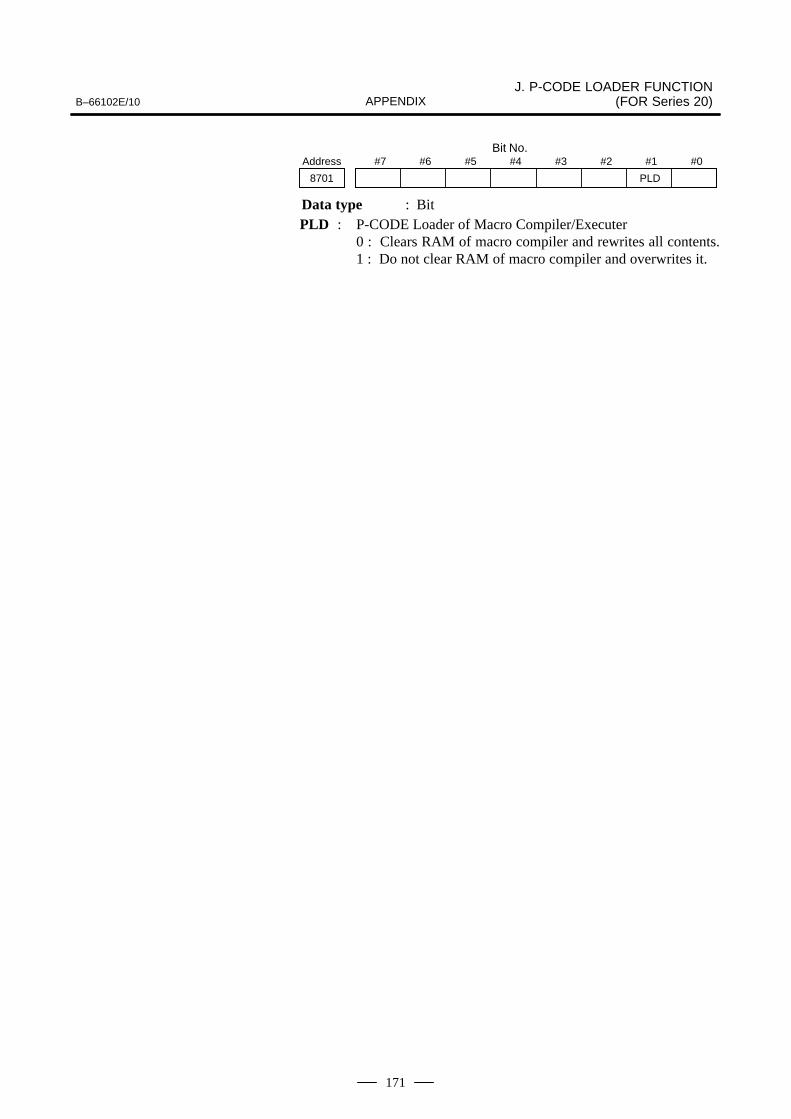
B–66102E/10J. P-CODE LOADER FUNCTION
(FOR Series 20)APPENDIX
171
Bit No.#7 #6 #5 #4 #3 #2 #1 #0Address
8701 PLD
Data type : BitPLD : P-CODE Loader of Macro Compiler/Executer
0 : Clears RAM of macro compiler and rewrites all contents.1 : Do not clear RAM of macro compiler and overwrites it.

J. P-CODE LOADER FUNCTION (FOR Series 20) B–66102E/10APPENDIX
172
Message Meaning
EXECUTER OPTION NOTHING Macro executer option is notequipped.
I/O OPTION NOTHING Reader/puncher control 1 option isnot selected.
I/O OPTION (CH2) NOTHING Reader/puncher control 2 option isnot selected.
ILLEGAL CHANNEL A channel other than channel 1 and 2is selected.
ILLEGAL CHARACTER Transferred data is not correct.
OVERRUN Overrun error.
FRAMING ERROR Framing error.
DSR SIGNAL OFF Communication error.
PARITY ERROR Data with no parity was transferred.
CHECK SUM ERROR Check sum error.
UNKNOWN F-ROM MODULE ORNOT MOUNTED
F-ROM module is unknown or notmounted.
ILLEGAL ID INFORMATION F-ROM file ID is incorrect.
NO SPACE There is no space in F- ROM module.
ERASE ERROR Deletion of F-ROM failed. F-ROMmay be defective.
PROGRAM ERROR Writing in F-ROM failed. F-ROM maybe defective.
J.4ALARMS

B–66102E/10 K. BOOT SYSTEM (FOR Series 15-B/15i-A)APPENDIX
173
K ���� ����� ���� ������ ����&��i���

K. BOOT SYSTEM (FOR Series 15-B/15i-A) B–66102E/10APPENDIX
174
The boot system of the Series 15-B/15i-A first loads the CNC systemsoftware (Flash Memory (F-ROM) → DRAM), then starts execution ofthe CNC software so that other software can be executed.
The Series 15-B/15i-A boot system supports the following systemmaintenance functions:
(1) Registering a file in F-ROM� Reads a file to flash memory from an MS-DOS format memory card
conforming to JEIDA V4.1.
(2) Checking a file (series and edition) in F-ROM
(3) Deleting a file from F-ROM
(4) Writing a file in F-ROM to a memory card
(5) Registering a ROM-format file stored on a macro cassette (ROMcassette) into F-ROM (only series 15-B)
This appendix describes how to register/delete macro programs into/fromthe Series 15-B/15i-A by using the above functions.
CAUTION1 Memory card handling
A memory card can be inserted or removed while the poweris on. While the boot system is running, however, insert orremove a memory card only while the main menu isdisplayed.
2 ROM cassette handling (Only Series 15-B)Turn off the power before attempting to insert or remove aROM cassette.
* For the Series 15–B and 15i–A, the display numbers and order maydiffer. The operation method is, however, the same. In the text of thismanual, the screens of the Series 15–B are used. For details of theSeries 15i–A, refer to the Maintenance Manual (B–63325EN).
K.1OUTLINE

B–66102E/10 K. BOOT SYSTEM (FOR Series 15-B/15i-A)APPENDIX
175
(a) SpecificationsFor the Series 15-B/15i-A boot system, commercially availablememory cards conforming to the following specification can be used:Format : JEIDA Ver. 4 or aboveCapacity : 512K bytes or more (for macro compilers)
(b) Size of MEM-format fileThe following table lists the maximum size of a MEM-format filewhich can be saved to a memory card:
MEM-format file Size in memory card
256K bytes 262272 bytes (256K bytes + 128 bytes)
512K bytes 524416 bytes (512K bytes + 128 bytes)
NOTEA MEM-format file cannot be split and saved to two or morememory card. Always prepare a memory card having acapacity greater than the size of the MEM-format file to besaved. Two or more MEM-format files can be saved to asingle memory card.
(c) Restrictions imposed on the boot systemThe boot system can access only those files in the root directory. Filesin a subdirectory cannot be accessed. In principle, for the bootsystem, do not use a memory card containing a subdirectory.
K.2MEMORY CARDSPECIFICATIONSAND RESTRICTIONS

K. BOOT SYSTEM (FOR Series 15-B/15i-A) B–66102E/10APPENDIX
176
The starting procedure depends on whether a MEM-format file is loadedfrom a memory card into F-ROM or whether a ROM-format file is loadedfrom a ROM cassette.
Starting procedureMain menu item ”Page Up” key, ”Page
Down” key”⇐”, ”⇒”
(Only Series 15–B)
SYSTEM DATA LOAD-ING
Loads a file from amemory card into F-ROM.
Loads a file from a ROMcassette into F-ROM.
SYSTEM DATA CHECK Lists the files, registered in F-ROM, and checksthe file.
SYSTEM DATA SAVE Saves a file, registered in F-ROM, to a memorycard.
”Page Up” key, ”Page Down” key: Turn the power on while holding downthe Page Up and Page Down keys.
”⇐”, ”⇒”: Turn the power on while holding down the ⇐ and ⇒ cursorkeys. (Only Series 15–B)
In both cases, the following boot system title screen appears.
RAM TEST : ENDROM TEST : END 6014 HDRAM ID : 0000SRAM ID : 0000FROM (CNC) : 0023FROM (PMC) : PASSCNC DATA SEARCH : sEND
Fig. K.3 (a) Boot System Title Screen
The contents vary with the system being used.
K.3STARTING THEBOOT SYSTEM

B–66102E/10 K. BOOT SYSTEM (FOR Series 15-B/15i-A)APPENDIX
177
After power-on, releasing the pressed keys causes the following bootsystem main menu to be displayed:
SYSTEM MONITOR
1. SYSTEM DATA LOADING 2. SYSTEM DATA CHECK 3. SYSTEM DATA SAVE 4. FILE DATA BACKUP 5. END
∗∗∗ MESSAGE ∗∗∗ SELECT MODE AND HIT INPUT KEY
Fig. K.3 (b) Boot System Main Menu

K. BOOT SYSTEM (FOR Series 15-B/15i-A) B–66102E/10APPENDIX
178
(1) Insert the memory card in the memory card interface of the CNC unit.
Memory card
PMC PSU
Series 15-B
Fig. K.4 (a) Mounting of a Memory Card
NOTEThe PMC slot is used as the memory card interface (Mainslot in case of series15i–A). The memory card can beinserted or removed while the power is turned on. When theboot system is active, make sure that the main menu [seeFig. K.3 (b)] is displayed on the screen before inserting orremoving the memory card. Otherwise, proper access is notmade, and the contents of the memory card files may bedestroyed.
(2) Turn on the power of the CNC unit while holding down the page-upand page-down keys. Then the boot system is activated. Refer to”K.3. STARTING THE BOOT SYSTEM”.
K.4REGISTERING AMEM–FORMAT FILE,STORED ON AMEMORY CARD,INTO F–ROM

B–66102E/10 K. BOOT SYSTEM (FOR Series 15-B/15i-A)APPENDIX
179
(3) Select ”2. SYSTEM DATA CHECK” using the cursor keys and pressthe input key. The contents of F-ROM are retrieved, and thefollowing information is displayed on the screen:
SYSTEM DATA CHECKFILE DIRECTORY 1. OPTIONA3 ( 2) 2. HELP MSG ( 2) 3. DG SERVO ( 1) 4. NC BASIC (10) 5. PCD 256A ( 2) 6. PMC-NA0B ( 1) 7. MCR-CMPA ( 2)END
∗∗∗ MESSAGE ∗∗∗ SELECT FILE AND HIT INPUT KEY
Fig. K.4 (b) DATA CHECK DIRECTORY Screen
Check this screen to see if any MEM format file are (hereinafter called aP–CODE file) registered. If a MEM format file is already registered, its filename is displayed (see the table below).
�245� K.4 R CODE 0�5� .26��
� Series 15–B
File name Description
PCD 256A For systems without a sub-CPU (256K bytes)
PCD 512A For systems without a sub-CPU (512K bytes)
PCD 256M For systems with a sub-CPU (256K bytes)
PCD 512M For systems with a sub-CPU (512K bytes)
� Series 15i–A
File name Description
PD1M 256K 256 KB for M system
PD1M 0.5M 512 KB for M system
PD1M 1.0M 1024 KB for M system
(4) If a P-CODE file is already registered, delete it. To delete a P-CODEfile, select it with the cursor, then press the ”delete” key. When noP-CODE file is registered, proceed to step 7.
(5) The message ”DELETE OK?” appears. Make sure that the selectedfile is a P-CODE file, then press the input key. If the wrong file hasbeen selected, press the cancel key. The DATA CHECKDIRECTORY screen [Fig. K.4 (b)] is then displayed again.
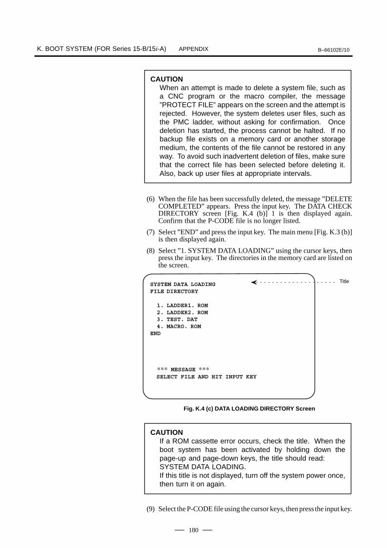
K. BOOT SYSTEM (FOR Series 15-B/15i-A) B–66102E/10APPENDIX
180
CAUTIONWhen an attempt is made to delete a system file, such asa CNC program or the macro compiler, the message”PROTECT FILE” appears on the screen and the attempt isrejected. However, the system deletes user files, such asthe PMC ladder, without asking for confirmation. Oncedeletion has started, the process cannot be halted. If nobackup file exists on a memory card or another storagemedium, the contents of the file cannot be restored in anyway. To avoid such inadvertent deletion of files, make surethat the correct file has been selected before deleting it.Also, back up user files at appropriate intervals.
(6) When the file has been successfully deleted, the message ”DELETECOMPLETED” appears. Press the input key. The DATA CHECKDIRECTORY screen [Fig. K.4 (b)] 1 is then displayed again.Confirm that the P-CODE file is no longer listed.
(7) Select ”END” and press the input key. The main menu [Fig. K.3 (b)]is then displayed again.
(8) Select ”1. SYSTEM DATA LOADING” using the cursor keys, thenpress the input key. The directories in the memory card are listed onthe screen.
SYSTEM DATA LOADINGFILE DIRECTORY
1. LADDER1. ROM 2. LADDER2. ROM 3. TEST. DAT 4. MACRO. ROMEND
∗∗∗ MESSAGE ∗∗∗ SELECT FILE AND HIT INPUT KEY
Title
Fig. K.4 (c) DATA LOADING DIRECTORY Screen
CAUTIONIf a ROM cassette error occurs, check the title. When theboot system has been activated by holding down thepage-up and page-down keys, the title should read:SYSTEM DATA LOADING.If this title is not displayed, turn off the system power once,then turn it on again.
(9) Select the P-CODE file using the cursor keys, then press the input key.

B–66102E/10 K. BOOT SYSTEM (FOR Series 15-B/15i-A)APPENDIX
181
(10)The message ”OK? INPUT/CANCEL” appears. To register theselected program, press the input key. To not register the selected filecancel, press the ”cancel” key. The DATA LOADING DIRECTORYscreen [see Fig. K.4 (c)] is then displayed again.
CAUTIONThe boot system registers any file having the acceptableformat. Once registration has started, it cannot be halted.If no backup file exists on a memory card or another storagemedium, the previously saved data of the file cannot berestored in any way. To avoid such inadvertent registrationof files, make sure that the correct file has been selectedbefore registering it. Also, back up files at appropriateintervals.
(11)When the file has been successfully registered, the message”PROGRAM COMPLETED” appears. Press the input key. TheDATA LOADING DIRECTORY screen [see Fig. K.4 (c)] is thendisplayed again.
(12)Select ”END” and press the input key. The main menu [Fig. K.3 (b)]is then displayed again.
(13)Select ”2. SYSTEM DATA CHECK” to retrieve the contents ofF-ROM. After confirming that the P-CODE file has been registered,press the input key to return the main menu [Fig. K.3 (b)].
(14)Select ”END” on the main menu and press the input key. The blinkingmessage ”LOADING CNC DATA” appears. The CNC starts upabout ten seconds later.
(15)Make sure that the registered P-CODE file operates normally.
(16)Remove the memory card from the memory card interface. The cardcan be removed even when the CNC power is on.

K. BOOT SYSTEM (FOR Series 15-B/15i-A) B–66102E/10APPENDIX
182
(1) Insert the memory card in the memory card interface of the CNC unitto activate the boot system. See steps 1 and 2 of Sec.K.4, Procedurefor registering a P-CODE file in a memory card to F-ROM.
(2) Select ”3. SYSTEM DATA SAVE” using the cursor keys, then pressthe input key. The contents of F-ROM are retrieved, and thefollowing information is displayed on the screen:
SYSTEM DATA SAVEFILE DIRECTORY 1. OPTIONA1 ( 2) 2. HELP MSG ( 2) 3. DGTL SRV ( 1) 4. NC BASIC (10) 5. PCD 256A ( 2) 6. PMC-NA0B ( 1) 7. MCR-CMPA ( 2)END
∗∗∗ MESSAGE ∗∗∗ SELECT FILE AND HIT INPUT KEY
Fig. K.5 DATA SAVE DIRECTORY Screen
(3) Select one of the P-CODE files listed below using the cursor, thenpress the input key.
� Series 15–B
File name Description
PCD 256A For systems without a sub-CPU (256K bytes)
PCD 512A For systems without a sub-CPU (512K bytes)
PCD 256M For systems with a sub-CPU (256K bytes)
PCD 512M For systems with a sub-CPU (512K bytes)
� Series 15i–A
File name Description
PD1M 256K 256 KB for M system
PD1M 0.5M 512 KB for M system
PD1M 1.0M 1024 KB for M system
NOTESystem files, such as the CNC program or the microcompiler, cannot be saved (if you attempt to save one ofthese files, the message ”PROTECT FILE” is displayed).
K.5SAVING AMEM–FORMAT FILEFROM F–ROM TO AMEMORY CARD

B–66102E/10 K. BOOT SYSTEM (FOR Series 15-B/15i-A)APPENDIX
183
(4) The message ”INPUT FILE NAME” appears. Input the file nameusing the MDI key. A file must be named according to MS-DOS filenaming rules; that is, a file name consisting of up to eight charactersfollowed by a three-character or shorter extension. During file nameinput:
� The cursor can be moved using the cursor (� and �) keys.� The cancel key functions as the backspace key.� Pressing the reset key displays the DATA SAVE DIRECTORY
screen [Fig. K.5] again.� Characters are input in the overwrite mode.
(5) After inputting the file name, press the input key to save the file.
(6) If the save operation terminates normally, the message ”SAVECOMPLETED” appears. Press the input key. The DATA SAVEDIRECTORY screen [Fig. K.5] is then displayed again.
(7) Select ”END” and press the input key. The main menu [Fig. K.3 (b)]is then displayed again.
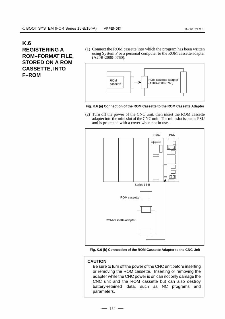
K. BOOT SYSTEM (FOR Series 15-B/15i-A) B–66102E/10APPENDIX
184
(1) Connect the ROM cassette into which the program has been writtenusing System P or a personal computer to the ROM cassette adapter(A20B-2000-0760).
ROM cassette adapter(A20B-2000-0760)
ROMcassette
Fig. K.6 (a) Connection of the ROM Cassette to the ROM Cassette Adapter
(2) Turn off the power of the CNC unit, then insert the ROM cassetteadapter into the mini slot of the CNC unit. The mini slot is on the PSUand is protected with a cover when not in use.
ROM cassette
PMC PSU
Series 15-B
ROM cassette adapter
Fig. K.6 (b) Connection of the ROM Cassette Adapter to the CNC Unit
CAUTIONBe sure to turn off the power of the CNC unit before insertingor removing the ROM cassette. Inserting or removing theadapter while the CNC power is on can not only damage theCNC unit and the ROM cassette but can also destroybattery-retained data, such as NC programs andparameters.
K.6REGISTERING AROM–FORMAT FILE,STORED ON A ROMCASSETTE, INTOF–ROM

B–66102E/10 K. BOOT SYSTEM (FOR Series 15-B/15i-A)APPENDIX
185
(3) Turn on the power of the CNC unit while holding down the cursor (←and →) keys, and the boot system is activated. Refer to ”K.3STARTING THE BOOT SYSTEM”.
(4) Check the contents of F-ROM. If a P-CODE file is already registered,delete it. For the deletion procedure, see 2 Procedure for registeringa P-CODE file in a memory card to F-ROM, steps (3) to (7) inSec.K.4.
(5) Select ”SYSTEM DATA LOADING” using the cursor keys, thenpress the input key. The following contents of the ROM cassette areread and displayed on the screen:
SYSTEM DATA LOADING (CASSETTE)
P-CODE 256K (WITHOUT SUB-CPU)
∗∗∗ MESSAGE ∗∗∗ SELECT FILE AND HIT INPUT KEY
Title
ROM type
Format file
Fig. K.6 (c) DATA LOADING DIRECTORY Screen (for ROM Cassette)
The type of mounted ROM cassette (ROM format file) is displayed (see the tablebelow). If the displayed ROM cassette type does not agree with that of theconnected ROM cassette, check the ROM cassette.
ROM cassette/ROM format file Description
1M-bit ROM without a sub-CPU P-CODE 256K (without sub-CPU)
2M-bit ROM without a sub- CPU P-CODE 512K (without sub-CPU)
1M-bit ROM with a sub-CPU P-CODE 256K (with sub-CPU)
2M-bit ROM with a sub-CPU P-CODE 512K (with sub-CPU)
CAUTIONIf an alarm related to the memory card occurs or whendisplaying memory card directories, confirm the title. Whenthe CNC unit has been activated with the cursor (� and �)keys pressed down, the title should read:SYSTEM DATA LOADING (CASSETTE)If this title is not displayed, activate the CNC unit again.
(6) The message ”OK? INPUT/CANCEL” appears. To register theP-CODE file, press the input key. To not resister the P-CODE file,press the ”cancel” key. Then the main menu [Fig. K.3 (b)] is thendisplayed again.
(7) When the file has been successfully registered, the message”PROGRAM COMPLETED” appears. Press the input key. Themain menu [Fig. K.3 (b)] is then displayed again.

K. BOOT SYSTEM (FOR Series 15-B/15i-A) B–66102E/10APPENDIX
186
(8) Select ”2. SYSTEM DATA CHECK” to retrieve the contents ofF-ROM. After confirming that the P-CODE file has been registeredin F-ROM. Press the input key to return the main menu [Fig. K.3 (b)].
(9) Turn off the power of the CNC unit, and remove the ROM cassetteadapter from the mini slot. After removing the adapter, place thecover over the slot to protect it.
CAUTIONAvoid using the CNC unit while the ROM cassette remainsin its mini slot. If the CNC unit is used without removing theROM cassette, the data stored in the ROM cassette takesprecedence, disabling the use of the micro compiler andP-CODE file program resident in F-ROM.
(10)Make sure that the registered P-CODE file operates normally.

B–66102E/10 K. BOOT SYSTEM (FOR Series 15-B/15i-A)APPENDIX
187
The following table lists the macro compiler/executer file namesdisplayed on the SYSTEM DATA CHECK screen:
� Series 15–B
Displayed name Type Description
MCR-CMPA S Macro compiler for systems without a sub-CPU
MCR-CMPM S Macro compiler for systems with a sub-CPU
PCD 256A U Macro program (256K bytes) for systems withouta sub-CPU
PCD 512A U Macro program (512K bytes) for systems withouta sub-CPU
PCD 256M U Macro program (256K bytes) for systems with asub-CPU
PCD 512M U Macro program (512K bytes) for systems with asub-CPU
� Series 15i–A
Displayed name Type Description
PD1M 256K U 256 KB for M system
PD1M 0.5M U 512 KB for M system
PD1M 1.0M U 1024 KB for M system
Type Symbols:
S : System file supplied by FANUC. The following operations cannotbe performed on system files:
� Saving to a memory card� Deletion from F-ROM
NOTEThe system files are necessary when a custom macroprogram is directly compiled by the Series 15-B.
U : Data file created by the user. All supported file access operationscan be performed.
K.7TYPES OF FILES INF–ROM
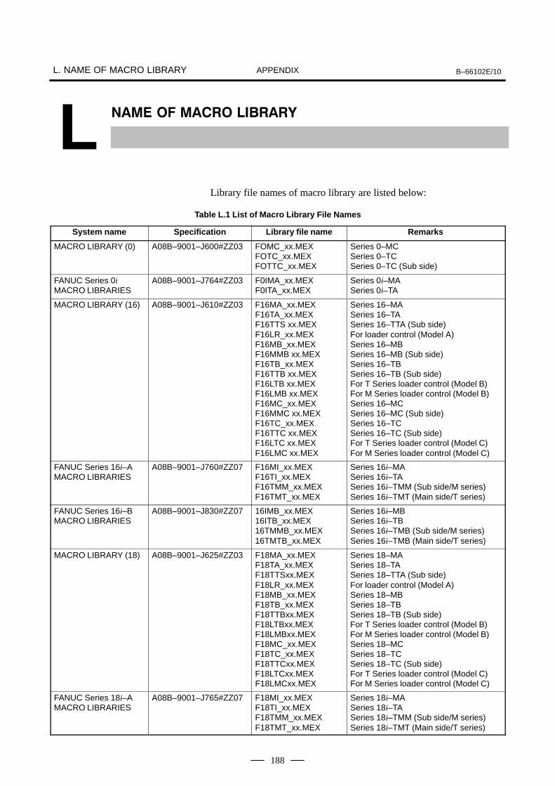
L. NAME OF MACRO LIBRARY B–66102E/10APPENDIX
188
L �� � �� ���� ������
Library file names of macro library are listed below:
Table L.1 List of Macro Library File Names
System name Specification Library file name Remarks
MACRO LIBRARY (0) A08B–9001–J600#ZZ03 FOMC_xx.MEXFOTC_xx.MEXFOTTC_xx.MEX
Series 0–MCSeries 0–TCSeries 0–TC (Sub side)
FANUC Series 0iMACRO LIBRARIES
A08B–9001–J764#ZZ03 F0IMA_xx.MEXF0ITA_xx.MEX
Series 0i–MASeries 0i–TA
MACRO LIBRARY (16) A08B–9001–J610#ZZ03 F16MA_xx.MEXF16TA_xx.MEXF16TTS xx.MEXF16LR_xx.MEXF16MB_xx.MEXF16MMB xx.MEXF16TB_xx.MEXF16TTB xx.MEXF16LTB xx.MEXF16LMB xx.MEXF16MC_xx.MEXF16MMC xx.MEXF16TC_xx.MEXF16TTC xx.MEXF16LTC xx.MEXF16LMC xx.MEX
Series 16–MASeries 16–TASeries 16–TTA (Sub side)For loader control (Model A)Series 16–MBSeries 16–MB (Sub side)Series 16–TBSeries 16–TB (Sub side)For T Series loader control (Model B)For M Series loader control (Model B)Series 16–MCSeries 16–MC (Sub side)Series 16–TCSeries 16–TC (Sub side)For T Series loader control (Model C)For M Series loader control (Model C)
FANUC Series 16i–AMACRO LIBRARIES
A08B–9001–J760#ZZ07 F16MI_xx.MEXF16TI_xx.MEXF16TMM_xx.MEXF16TMT_xx.MEX
Series 16i–MASeries 16i–TASeries 16i–TMM (Sub side/M series)Series 16i–TMT (Main side/T series)
FANUC Series 16i–BMACRO LIBRARIES
A08B–9001–J830#ZZ07 16IMB_xx.MEX16ITB_xx.MEX16TMMB_xx.MEX16TMTB_xx.MEX
Series 16i–MBSeries 16i–TBSeries 16i–TMB (Sub side/M series)Series 16i–TMB (Main side/T series)
MACRO LIBRARY (18) A08B–9001–J625#ZZ03 F18MA_xx.MEXF18TA_xx.MEXF18TTSxx.MEXF18LR_xx.MEXF18MB_xx.MEXF18TB_xx.MEXF18TTBxx.MEXF18LTBxx.MEXF18LMBxx.MEXF18MC_xx.MEXF18TC_xx.MEXF18TTCxx.MEXF18LTCxx.MEXF18LMCxx.MEX
Series 18–MASeries 18–TASeries 18–TTA (Sub side)For loader control (Model A)Series 18–MBSeries 18–TBSeries 18–TB (Sub side)For T Series loader control (Model B)For M Series loader control (Model B)Series 18–MCSeries 18–TCSeries 18–TC (Sub side)For T Series loader control (Model C)For M Series loader control (Model C)
FANUC Series 18i–AMACRO LIBRARIES
A08B–9001–J765#ZZ07 F18MI_xx.MEXF18TI_xx.MEXF18TMM_xx.MEXF18TMT_xx.MEX
Series 18i–MASeries 18i–TASeries 18i–TMM (Sub side/M series)Series 18i–TMT (Main side/T series)

B–66102E/10 L. NAME OF MACRO LIBRARYAPPENDIX
189
System name RemarksLibrary file nameSpecification
FANUC Series 18i–BMACRO LIBRARIES
A08B–9001–J831#ZZ07 F18IMB_xx.MEXF18ITB_xx.MEX18TMMB_xx.MEX18TMTB_xx.MEX
Series 18i–MBSeries 18i–MBSeries 18i–TMB (Sub side/M series)Series 18i–TMB (Main side/T series)
MACRO LIBRARY (16 P/L/W)
A08B–9001–J613#ZZ03 F16LA_xx.MEXF16PA_xx.MEXF16WA_xx.MEXF16LB_xx.MEXF16PB_xx.MEX
Series 16–LASeries 16–PASeries 16–WASeries 16–LBSeries 16–PB
MACRO LIBRARY(15A)
A08B–9001–J620#ZZ03 F15_A_xx.MEXF15_B_xx.MEX
F15_C_xx.MEX
F15_D_xx.MEX
F15_E_xx.MEX
Series 15–A W/0 subSeries 15–A with sub (Main side 256Kbyte)Series 15–A with sub (Sub side 256Kbyte)Series 15–A with sub (Main side 512Kbyte)Series 15–A with sub (Sub side 512Kbyte)
MACRO LIBRARY(15B)
A08B–9001–J640#ZZ03 F15B_Axx.MEXF15B_Bxx.MEXF15B_Cxx.MEX
F15B_Dxx.MEX
F15B_Exx.MEX
F15B_Fxx.MEX
Series 15–B W/O sub 256K byteSeries 15–B W/O sub 512K byteSeries 15–B with sub (Main side 256Kbyte)Series 15–B with sub (Sub side 256Kbyte)Series 15–B with sub (Main side 512Kbyte)Series 15–B with sub (Sub side 512Kbyte)
FANUC Series 15iMACRO LIBRARIES
A08B–9001–J640#ZZ07 F15IA_xx.MEX For Series 15i–MA
MACRO LIBRARY A08B–9001–J690#ZZ03 F20MA_xx.MEX Series 21–MB (D201 series)(21MB) F21MB_xx.MEX Series 21–MB (DDA1 series)
MACRO LIBRARY A08B–9001–J633#ZZ03 PMDT_xx.MEX Series 21–TA (8860 series)(21TA) F21TA_xx.MEX Series 21–TA (8865,8866 series)
MACRO LIBRARY(21TB)
A08B–9001–J639#ZZ03 F21TB_xx.MEX Series 21–TB (controller A) (DE01 se-ries)
F21TBN_xx.MEX Series 21–TB (controller B) (DEA1 se-ries)
MACRO LIBRARY(21TB)
A08B–9001–J639#ZZ03 F21LTB_xx.MEX Series 21–TB (loader control)
FANUC Series 21i–AMACRO LIBRARIES
A08B–9001–J769#ZZ07 F21MI_xx.MEXF21TI_xx.MEX
Series 21i–MASeries 21i–TA
FANUC Series 21i–BMACRO LIBRARIES
A08B–9001–J832#ZZ07 F21IMB_xx.MEXF21ITB_xx.MEX
Series 21i–MBSeries 21i–TB
MACRO LIBRARY (20F G)
A08B–9001–J670#ZZ03 DZ70_xx.MEX Series 20–FA (512K byte)
MACRO LIBRARY (20F GP)
A08B–9001–J671#ZZ03 DZ71_xx.EE1DZ71_xx.EE2
With Series 20–FA Guidance Program-ming function (1M byte)POC PRG.SRCFACE PRG.SRCDRILL PR.SRCSIDE PRG.SRCWith Series 20–TA Guidance Program-ming function

L. NAME OF MACRO LIBRARY B–66102E/10APPENDIX
190
System name RemarksLibrary file nameSpecification
MACRO LIBRARY (20F GB)
A08B–9001–J672#ZZ03 DZ72_xx.MEX Series 20–FA (1M byte)
MACRO LIBRARY (20F GPB)
A08B–9001–J673#ZZ03 DZ73_xx.EX1DZ73_xx.EX2
With Series 20–FA Guidance Program-ming function (1.5M byte)POC PRG.SRCFACE PRG.SRCDRILL PR.SRCSIDE PRG.SRCWith Series 20–TA Guidance Program-ming function
MACRO LIBRARY (20T G)
A08B–9001–J675#ZZ03 DZ75_xx.MEX Series 20–TA (512K byte)
MACRO LIBRARY (20T GP)
A08B–9001–J676#ZZ03 DZ76_xx.EX1DZ76_xx.EX2
With Series 20–TA Guidance Program-ming function (1M byte)
MACRO LIBRARY (20T GP)
A08B–9001–J677#ZZ03 DZ77_xx.MEX Series 20–TA (1M byte)
MACRO LIBRARY (20T GPB)
A08B–9001–J678#ZZ03 DZ78_xx.EX1DZ78_xx.EX2
With Series 20–TA Guidance Program-ming function (1.5M byte)
MACRO LIBRARY (20F B)
A08B–9001–J750#ZZ03 DZ62_xx.MEX For Series 20–FA (1 MB)The FANUC standard machining guid-ance cannot be used.
MACRO LIBRARY (20F GB)
A08B–9001–J751#ZZ03 DZ63_xx.EX1DZ63_xx.EX2
For Series 20–FA (1.5 MB)The FANUC standard machining guid-ance cannot be used.With guidance programming function
NOTExx in a library file name indicates the edition of the library.
Executer file is defined as follows.
Series 15–A
CNC system/ROM cassette type CNC= CNC2= CNC3=
without SUB CPU / 256Kbyte F15_A_xx.MEX nothing
without SUB CPU / 512Kbyte F15_A_xx.MEX nothing
with SUB CPU / 256Kbyte F15_B_xx.MEX F15_C_xx.MEXnothing
with SUB CPU / 512Kbyte F15_D_xx.MEX F15_E_xx.MEX
Series 15–B
CNC system/Kind of P–CODE file CNC= CNC2= CNC3=
without SUB CPU / 256Kbyte F15B_Axx.MEX nothing
without SUB CPU / 512Kbyte F15B_Bxx.MEX nothing
with SUB CPU / 256Kbyte F15B_Cxx.MEX F15B_Dxx.MEXnothing
with SUB CPU / 512Kbyte F15B_Exx.MEX F15B_Fxx.MEX
B–66102E/10 M. PARAMETERSAPPENDIX
191
M ���� �����
This section describes the compiler parameters and executor parameterfor the CNC system excluding Series 15.
For the parameters of Series 15, refer to the manuals listed below.,
1) FANUC Series 15 Programming Manual (Macro compiler/Macroexecutor) (B–61213E–1)
2) FANUC Series 15–MODEL B Programming Manual (MacroCompiler/Macro executor) (B–62073E–2)

M. PARAMETERS B–66102E/10APPENDIX
192
The compile parameters are initialized to the values set in the P–CODEfile at power–up. The parameters cannot be changed from MDI or others.However, parameters 8547 and 8548, which are used for debugging, canbe set from MDI.
Bit No.#7 #6 #5 #4 #3 #2 #1 #0Address
8500 LD6 R10 R05
R05R10 Size of P–CODE file
R10 R05 Size of P–CODE file
0 0 256Kbyte
0 1 512Kbyte
1 0 1Mbyte
1 1 Not defined
LD6 = 1: This bit must always be set 1.Bit No.
#7 #6 #5 #4 #3 #2 #1 #0Address
8502 NPE TMC EUI VAR DBG SBK DIR
DIR = 0 : The program list screen does not show P–CODE macroprogram numbers.
= 1 : The program list screen shows P–CODE macro programnumbers.
NOTEP–CODE macro program names cannot be displayed.
SBK = 0 : When the conversational macro or auxiliary macro is executed with the debug function, continuous executionis performed.
= 1 : When the conversational macro or auxiliary macro is executed with the debug function, single–block execution is performed.
DBG = 0 : The debug function is not used.
= 1 : The debug function is used.
VAR = 0 : The P–CODE macro variable screen cannot be displayed.
= 1 : The P–CODE macro variable screen can be displayed.
EUI = 0 : The P–CODE macro uses UI00 to UI15 and UO00 to UO15 as UI/UO signals.
= 1 : The P–CODE macro uses EUI00 to EUI15 and EUO00to EUO15 as UI/UO signals.
TMC = 0 : An execution macro call by a T code is a subprogram callof O90000.
= 1 : An execution macro call by a T code is a macro call of O90008.
NPE = 0 : Under RS–232–C control, % (EOF) is automatically output.
= 1 : Under RS–232–C control, % (EOF) is not automaticallyoutput.
M.1SERIES 15i COMPILEPARAMETERS

B–66102E/10 M. PARAMETERSAPPENDIX
193
Bit No.#7 #6 #5 #4 #3 #2 #1 #0Address
8503 MV7 MV6 MV5 MV4 MV3 MV2 MV1 MV0
8504 MVA MV9 MV8 ECK
= 0 : P–CODE macro common variables (#100 to #999) are alsoused as custom macro common variables.
= 1 : P–CODE macro common variables (#100 to #999) are independent of custom macro common variables.The following bits of the two parameters set the range ofcommon variables.
No.8503MV0 : #100 to 149 MV1 : #150 to 199 MV2 : #500 to 549 MV3 : #550 to 599
MV4 : #600 to 699 MV5 : #700 to 799 MV6 : #800 to 899 MV7 : #900 to 999
No. 8504MV8 : #200 to 299 MV9 : #300 to 399 MVA : #400 to 499
ECK = 0 : Command input variable #8501 does not expand the command keys that can be read.
= 1 : Command input variable #8501 expands the command keys that can be read.After the expansion, the following command keys can beread:
Function menu key
22 Function key
POS 23 Function key
PROG 24
Function key
OFFSETSETTING 25 Function
keyCUSTOM 26 Function
keySystem 27
Function key
MESSAGE 28 Function key
GRAPH 29 Function key 30
NOTEIf the expansion is performed, pressing any of the commandkeys does not terminate the conversational macro function.Accordingly, the corresponding screen is not displayed.Conversational macro start control variable #8510 must beset to 0 to terminate the conversational macro function.
Bit No.#7 #6 #5 #4 #3 #2 #1 #0Address
8507 PWS NTV CAN
CAN = 0 : While the system is waiting for data transmission or reception under reader/puncher interface control, no interruption can be made by pressing the CAN key.
= 1 : While the system is waiting for data transmission or reception under reader/puncher interface control, an interruption can be made by pressing the CAN key.
NTV = 0 : G336 (data transmission) outputs a blank character for performing a TV check.
= 1 : G336 (data transmission) does not output a blank character for performing a TV check.

M. PARAMETERS B–66102E/10APPENDIX
194
PWS = 0 : The P–CODE work number search is disabled.
= 1 : The P–CODE work number search is enabled.Bit No.
#7 #6 #5 #4 #3 #2 #1 #0Address
8508 PGR CLG B5C SSC TEC AC2 AC1
AC1 = 0 : A subprogram call (O9004) by a special code is disabled.
= 1 : A subprogram call (O9004) by a special code is enabled.
AC2 = 0 : A subprogram call (O9005) by a special code is disabled.
= 1 : A subprogram call (O9005) by a special code is enabled.
TEC = 0 : A subprogram or macro call by a T code is disabled.
= 1 : A subprogram or macro call by a T code is enabled.
SSC = 0 : A subprogram call by an S code is disabled.
= 1 : A subprogram call by an S code is enabled.
BSC = 0 : A subprogram call by the secondary miscellaneous function code is disabled.
= 1 : A subprogram call by the secondary miscellaneous function code is enabled.
CLG = 0 : Cutting distance summation/preset (#8554) is disabled.
= 1 : Cutting distance summation/preset (#8554) is enabled.
PCR = 0 : CNC program referencing/writing, cutting distance summation/preset, and RS–232–C control are disabled.
= 1 : CNC program referencing/writing, cutting distancesummation/preset, and RS–232–C control are enabled.
Bit No.#7 #6 #5 #4 #3 #2 #1 #0Address
8509 GMP PTC MCT EV2 EV1
EV1 = 0 : Expansion P–CODE variables (#40000 and after) are floating–point data.
= 1 : Expansion P–CODE variables (#40000 and after) are integer data.
EV2 = 0 : P–CODE variables (#30000 and after) are floating–pointdata.
= 1 : P–CODE variables (#30000 and after) are integer data.
MCT = 0 : A modal macro call by a G code is a move command call(equivalent to G66).
= 1 : A modal macro call by a G code is a call in each block (equivalent to G66.1).
PTC = 0 : When a macro variable is output, EOB is output as LF.
= 1 : When a macro variable is output, EOB is output as LF CRCR.
GMP = 0 : The following calls are enabled: call by an M, S, T, secondary miscellaneous function, or special code or byan axis address during a G–code call, and a G–code callduring a call by an M, S, T, secondary miscellaneous function, or special code or by an axis address.

B–66102E/10 M. PARAMETERSAPPENDIX
195
= 1 : The following calls are disabled: call by an M, S, T, secondary miscellaneous function, or special code or byan axis address during a G–code call, and a G–code callduring a call by an M, S, T, secondary miscellaneous function, or special code or by an axis address. (This typeof call is processed as a normal NC command.)
Address
8510 M code of subprogram call for calling program 9001
8511 M code of subprogram call for calling program 9002
8512 M code of subprogram call for calling program 9003
Valid data range : 1 to 9999 (excluding 30, 98, and 99)These parameters specify M codes of subprogramcalls for calling programs 9001, 9002, and 9003.
Address
8513 G code of subprogram call for calling program 9010
8514 G code of subprogram call for calling program 9011
8515 G code of subprogram call for calling program 9012
8516 G code of subprogram call for calling program 9013
8517 G code of subprogram call for calling program 9014
8518 G code of subprogram call for calling program 9015
8519 G code of subprogram call for calling program 9016
8520 G code of subprogram call for calling program 9017
8521 G code of subprogram call for calling program 9018
8522 G code of subprogram call for calling program 9019
Valid data range : –999 to 999 (excluding 0, 65, 66, and 67)These parameters specify G codes of macro calls forcalling programs 9010 to 9019.

M. PARAMETERS B–66102E/10APPENDIX
196
Address
8523 M code of subprogram call for calling program 9020
8524 M code of subprogram call for calling program 9021
8525 M code of subprogram call for calling program 9022
8526 M code of subprogram call for calling program 9023
8527 M code of subprogram call for calling program 9024
8528 M code of subprogram call for calling program 9025
8529 M code of subprogram call for calling program 9026
8530 M code of subprogram call for calling program 9027
8531 M code of subprogram call for calling program 9028
8532 M code of subprogram call for calling program 9029
Valid data range : 1 to 9999 (excluding 30, 98, and 99)These parameters specify M codes of macro calls forcalling programs 9020 to 9029.
Address
8533 M code of subprogram call for calling a user program
Valid data range : 1 to 9999 (excluding 30, 98, and 99)This parameter specifies an M code of subprogramcall for calling a user program.
Address
8536 Main program number of conversational macro
Valid data range : 1 to 99999999This parameter specifies the main program numberof the conversational macro.
NOTE1 The program number of this parameter is set in the
conversational macro execution control variable atpower–up.
Address
8537 Main program number of auxiliary macro
Valid data range : 1 to 99999999This parameter specifies the main program numberof the auxiliary macro.
NOTE1 The program number of this parameter is set in the auxiliary
macro execution control variable at power–up.
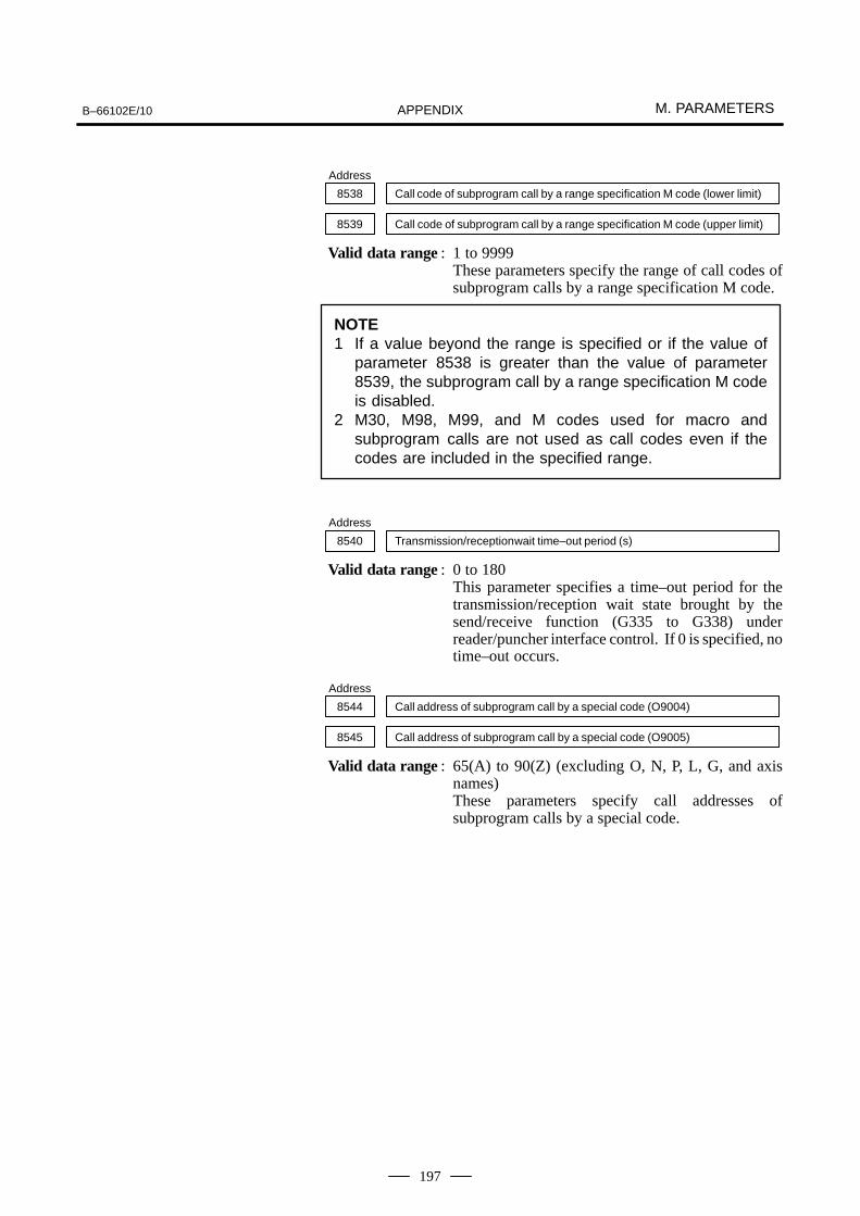
B–66102E/10 M. PARAMETERSAPPENDIX
197
Address
8538 Call code of subprogram call by a range specification M code (lower limit)
8539 Call code of subprogram call by a range specification M code (upper limit)
Valid data range : 1 to 9999These parameters specify the range of call codes ofsubprogram calls by a range specification M code.
NOTE1 If a value beyond the range is specified or if the value of
parameter 8538 is greater than the value of parameter8539, the subprogram call by a range specification M codeis disabled.
2 M30, M98, M99, and M codes used for macro andsubprogram calls are not used as call codes even if thecodes are included in the specified range.
Address
8540 Transmission/reception wait time–out period (s)
Valid data range : 0 to 180This parameter specifies a time–out period for thetransmission/reception wait state brought by thesend/receive function (G335 to G338) underreader/puncher interface control. If 0 is specified, notime–out occurs.
Address
8544 Call address of subprogram call by a special code (O9004)
8545 Call address of subprogram call by a special code (O9005)
Valid data range : 65(A) to 90(Z) (excluding O, N, P, L, G, and axisnames)These parameters specify call addresses ofsubprogram calls by a special code.

M. PARAMETERS B–66102E/10APPENDIX
198
Address
8546 Number of G–code macro calls (multiple) to be defined
8551 First G code for G–code macro calls (multiple)
8552 First program number of G–code macro calls (multiple)
Valid data range : Parameter 8546: 1 to 255Parameter 8551: –9999 to 9999 (excluding 0)Parameter 8552: 1 to 9999Parameter 8546 specifies the number of G–codemacro calls (multiple) to be programmed. Parameter8551 specifies the first one of the code numbers usedfor the calls. Parameter 8552 specifies the firstprogram number of the execution macro.If a negative value is specified in parameter 8551, amodal call is executed. The MCT bit (bit 2 ofparameter 8509) specifies whether the modal call isexecuted as a move command call (G66) or as a callin each block (G66.1).
NOTEThe G–code macro call (multiple) is disabled in the followingcases:
1 A value beyond the valid range is specified in any of theparameters.
2 The highest G code exceeds 9999.3 The highest program number exceeds 9999.
G65, G66, G67, and G codes specified for macro calls arenot used as call codes even if they are included in the range.
Address
8547 Number of the conversational or auxiliary macro program in which a break occurs
Valid data range : 0 to 99999999This parameter specifies the number of theconversational or auxiliary macro program in whicha break is caused by the debug function.
NOTEIf either this parameter or parameter 8548 is set to anon–zero value when the conversational macro isexecuted, a break is enabled. The program numberspecified in this parameter and the sequence numberspecified in parameter 8548 are set as break conditions.

B–66102E/10 M. PARAMETERSAPPENDIX
199
Address
8548 Number of the conversational or auxiliary macro sequence in which a break occurs
Valid data range : 0 to 99999999This parameter specifies the number of theconversational or auxiliary macro sequence in whicha break is caused by the debug function.
NOTEIf either this parameter or parameter 8547 is set to anon–zero value when the conversational macro isexecuted, a break is enabled. The sequence numberspecified in this parameter and the program numberspecified in parameter 8547 are set as break conditions.
Address
8549 Number of P–CODE variables (#30000 and after)
Valid data range : 0 to 100This parameter specifies the number of P–CODEvariables.The setting of the EV2 bit (bit 1 of parameter 8509)affects the number of variables that are actuallydefined, as follows:When EV2 is set to 0 (floating point data):
(Value of parameter 8549)�40Wen EV2 is set to 1 (integer data):
(Value of parameter 8549)�100
Address
8550 Number of expansion P–CODE variables (#4000 and after)
Valid data range : 0 to 1970This parameter specifies the number of expansionP–CODE variables.The setting of the EV1 bit (bit 0 of parameter 8509)affects the number of variables that are actuallydefined, as follows:When EV1 is set to 0 (floating–point data):
(Value of parameter 8550)�10Wen EV1 is set to 1 (integer data):
(Value of parameter 8550)�30Bit No.
#7 #6 #5 #4 #3 #2 #1 #0Address
8555 X08 X07 X06 X05 X04 X03 X02 X01
8556 X16 X15 X14 X13 X12 X10 X09 X08
8557 X24 X23 X22 X21 X20 X19 X18 X17
= 0 : A macro call by an axis address is disabled.
= 1 : A macro call by an axis address is enabled.

M. PARAMETERS B–66102E/10APPENDIX
200
The bits of the parameters select different axes.No.8555
X01 : First axisX02 : Second axis
:No. 8504 :
X24 : Twenty–fourth axisBit No.
#7 #6 #5 #4 #3 #2 #1 #0Address
8558 ACA P98 15I PWT XDL ACS
ACS = 0 : A macro call by an axis address always calls O9009.= 1 : A macro call by an axis address calls a program
depending on the axis.First axis � Calls O9031.Second axis � Calls O9032.
:n–th axis � Calls a program having an O number of
9030 + n.XDL = 0 : Interlock along an axis is disabled.
= 1 : Interlock along an axis is enabled.PWT = 0 : The conversational macro function is not executed at
power–up.= 1 : The conversational macro function is executed at
power–up.The position display screen is normally displayed atpower–up, but the conversational macro function can beexecuted to display a special screen.
15I = 0 : The macro executor function follows Series 15–B compatible specifications.
= 1 : The macro executor function follows original specifications for the Series 15i.This bit selects the following specifications:
Function Series 15–B specifications(15I = 0)
Series 15i specifica-tions (15I = 1)
Character coordi-nate system
X0 to 73, Y0 to 26 X0 to 79, Y0 to 26
System display partSoft key frame
FS15–B FS15i
Key input line Y22 Y23
Command key inputvariable by parame-ter 8501
The INSERT, ALTER, andDELETE keys cannot beread.
The keys can be read.INSERT : 31ALTER : 32DELETE : 33
Method of execut-ing both auxiliarymacro and con-versational macro
Sequential execution (Afterthe program end command ofthe auxiliary macro isexecuted, the conversationalmacro is executed.)
Parallel execution
Alarm information ofwindow function(foreground PSalarm of alarm basicflags)
When a foreground PS alarmor MC alarm is issued
When a foreground PSalarm is issued. AnMC alarm can be readwith basic flag 2.)

B–66102E/10 M. PARAMETERSAPPENDIX
201
P98 = 0 : The execution macro for P–CODE work number searchis called by a macro call. A local variable used by the execution macro cannot be used in the main program.
= 1 : The execution macro for P–CODE work number searchis called by a subprogram call. A local variable used bythe execution macro is taken over to the main program.
ACA = 0 : A macro call by a T code or axis address always passesan argument without decimal point as an integer value.
= 1 : A macro call by a T code or axis address passes an argument without decimal point, adding a decimal pointaccording to the setting of the DPI bit (bit 0 of parameter2400).
Address
8570 Graphic coordinate system shift amount (X–axis)
8571 Graphic coordinate system shift amount (Y–axis)
Valid data range : –320 to 319 (X–axis), –216 to 231 (Y–axis)These parameters specify the shift amounts of thegraphic coordinate system in dots.
Address
8572 Address of the interlock mode signal of an axis
8573 Bit position of the interlock mode signal of an axis
Valid data range : 0 to 7These parameters specify a PMC internal relay (Rarea) signal that determines the control mode of theinterlock function of an axis.Address : R area numberBit position : Bit position of the signal
NOTEThe interlock function of an axis is disabled when:1 The address refers to a position beyond the R area.2 The bit position is incorrect.
Address
8574 P–CODE common variable (#500 to #999) protect range (top)
8575 P–CODE common variable (#500 to #999) protect range (bottom)
Valid data range : 500 to 999These parameters specify the range ofbattery–backed P–CODE common variables (#500to #999) to be write–protected.
NOTEIf a value beyond the range is specified or if the value ofparameter 8574 is larger than the value of parameter 8575,no write protection is provided.

M. PARAMETERS B–66102E/10APPENDIX
202
Address
8576 P–CODE common variable (#200 to #499) protect range (top)
8577 P–CODE common variable (#200 to #499) protect range (bottom)
Valid data range : 200 to 499These parameters specify the range ofbattery–backed P–CODE common variables (#200to #499) to be write–protected.
NOTEIf a value beyond the range is specified or if the value ofparameter 8576 is larger than the value of parameter 8577,no write protection is provided.
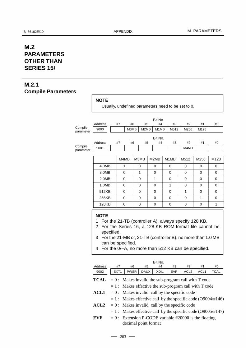
B–66102E/10 M. PARAMETERSAPPENDIX
203
NOTEUsually, undefined parameters need to be set to 0.
Bit No.#7 #6 #5 #4 #3 #2 #1 #0Address
9000 M3MB M2MB M1MB M512 M256 M128Compileparameter
Bit No.#7 #6 #5 #4 #3 #2 #1 #0Address
9001 M4MBCompileparameter
M4MB M3MB M2MB M1MB M512 M256 M128
4.0MB 1 0 0 0 0 0 0
3.0MB 0 1 0 0 0 0 0
2.0MB 0 0 1 0 0 0 0
1.0MB 0 0 0 1 0 0 0
512KB 0 0 0 0 1 0 0
256KB 0 0 0 0 0 1 0
128KB 0 0 0 0 0 0 1
NOTE1 For the 21-TB (controller A), always specify 128 KB.2 For the Series 16, a 128-KB ROM-format file cannot be
specified.3 For the 21-MB or, 21-TB (controller B), no more than 1.0 MB
can be specified.4 For the 0�–A, no more than 512 KB can be specified.
Bit No.#7 #6 #5 #4 #3 #2 #1 #0Address
9002 EXT1 PWSR DAUX XDIL EVF ACL2 ACL1 TCAL
TCAL = 0 : Makes invalid the sub-program call with T code
= 1 : Makes effective the sub-program call with T code
ACL1 = 0 : Makes invalid call by the specific code
= 1 : Makes effective call by the specific code (O9004/#146)ACL2 = 0 : Makes invalid call by the specific code
= 1 : Makes effective call by the specific code (O9005/#147)
EVF = 0 : Extension P-CODE variable #20000 is the floating decimal point format
M.2PARAMETERSOTHER THANSERIES 15i
M.2.1Compile Parameters

M. PARAMETERS B–66102E/10APPENDIX
204
= 1 : Extension P-CODE variable #20000 is the fixed decimalformat
XDIL = 0 : Axis interlock function invalid
= 1 : Axis interlock function valid
DAUX = 0 : Does not make the CUSTOM screen appear at power on
= 1 : Makes CUSTOM screen appear at power on
PWSR = 0 : P CODE work number search function invalid
= 1 : P CODE work number search valid
EXT1 = 0: Extension functions invalid
= 1: Extension functions valid (RS-232-C control, NC program access)
CAUTIONWhen EXT1=1, part program memory reduces by 1.63m � Series 16/18–A (part program storage of up to 80m)� Series 20 (part program storage of up to 80m)� Series 21–MB (D201 series, part program storage of up
to 80m)� Series 21–TB (control unit A)
Bit No.#7 #6 #5 #4 #3 #2 #1 #0Address
9003 PTCR KY20 HRGR ONMSK
ONMSK= 0 : The O and N numbers are displayed on the CUSTOM screen.
= 1 : The O and N numbers are not displayed on the CUSTOMscreen.
HRGR = 0 : Standard mode graphic display
= 1 : High resolution graphic mode display (set to H1I usually)
KY20 = 0 : Not +� to #8501 with decimal point input by key inputvariables
= 1 : +� to #8501 with decimal input by key input variables(+�: +20 for a display with 7 soft keys, +40 for a display with 12 soft keys)
PTCR = 0 : Does not output ”CR” code twice in P-CODE variable outputting
= 1 : Output ”CR” code twice in P-CODE variable outputtingBit No.
#7 #6 #5 #4 #3 #2 #1 #0Address
9004 CUTLG NOP_B HRGC IMG SP_G_C SP_G_B
SP_G_B, SP_G_C00 : Standard G code system
01 : G code system B
10 : G code system C
11 : G code system C

B–66102E/10 M. PARAMETERSAPPENDIX
205
IMG = 0 : 16-T type (Special G code)
= 1 : 16-G type (Special G code)
HRGC = 0 : 9I high resolusion monochrome CRT, standard
= 1 : 9I high resolution monochrome CRT, brightness modulation mode setting (paint)
NOP_B = 0 : When no other address is specified in a block that callsa subprogram by a T or M code, the block is executed.
= 1 : The block is not executed.
CUTLG = 0 : Does not count cutting distance
= 1 : Count cutting distanceBit No.
#7 #6 #5 #4 #3 #2 #1 #0Address
9005 TMACC AXCLS AX4CL AX3CL AX2CL AX1CL
AX1CL = 0 : Macro program call by the 1st address is invalid= 1 : Macro program call by the 1st address is valid
AX2CL = 0 : Macro program call by the 2nd address is invalid= 1 : Macro program call by the 2nd address is valid
AX3CL = 0 : Macro program call by the 3rd address is invalid= 1 : Macro program call by the 3rd address is valid
AX4CL = 0 : Macro program call by the 4th address is invalid= 1 : Macro program call by the 4th address is valid
AXCLS = 0 : Always program O9009 is called irrespective of specified axes.
= 1 : The program number to be called depends on a specifiedaxis:Program O9031 is called when 1st axis is specified.Program O9032 is called when 2nd axis is specified.
: :Program O9038 is called when 8th axis is specified.
TMACC= 0 : Macro call by T code is invalid= 1 : Macro call by T code is valid
Bit No.#7 #6 #5 #4 #3 #2 #1 #0Address
9006 NNUM US19W CNCHG DAUXR STDM KEYC DIOC
DIOC = 0 : Standard UI:G54/G55 and UO:F54/F55 are used for UI/UO(#1000-#1132) of execution macro/ conversational macro.
= 1 : UI:G82/G83 and UO:F84/F85 are used for UI/UO(#1000-#1132) of execution macro/ conversational macro.
KEYC = 0 : When KEY switch =0, completion code #8529=254 in anaccess to NC program
= 1 : KEY switch is not cheched in an access to NC program
STDM = 0 : The mode and status display is changed on the USER-1,USER-2, and USER-3 screens on which the conversational macro screen is displayed.
= 1 : The mode and status display is left unchanged on the USER-1, USER-2, and USER-3 screens on which the conversational macro screen is displayed.

M. PARAMETERS B–66102E/10APPENDIX
206
DAUXR : The conversational macro screen is displayed when power is turned on while the system is in the emergencystop state or external reset state. (Parameter DAUX (No. 9002, #5) must also be set to 1.)
CNCHG : Execution of the conversational macro is continued whenthe CUSTM key is pressed while the conversational macro screen is displayed.
US19W : The screen for the 9” CRT type is displayed on the 14”CRT type. (USER-1 screen)
NNUM = 0: When data input control is valid for the CUSTOM screen,the NUM prompt is displayed.
= 1: When data input control is valid for the CUSTOM screen,the NUM prompt is not displayed.
Bit No.#7 #6 #5 #4 #3 #2 #1 #0Address
9007 US19WK TIVR2 TIVR1 TIDSP
TIDSP : The common conversational macro screen for the 2–pathcontrol is specified.
NOTEThis setting is validated only for the PATH-2 cassette.Both TTDSP and CNCHG (No. 9006, #4) cannot be set to1 at the same time.)
TIVR1 : Common conversational macro variables (#10000 to #19999) are specified. (1: For variables #10000 to #19999, areas #10000 to #19999 of the other path are used.)
TIVR2 : Common conversational macro variables (#20000 to #29999) are specified. (1: For variables #20000 to #29999, areas #20000 to #29999 of the other path are used.)
US19WK= 0 : When display with 12 soft keys is selected, the positionof the key–in line is not changed on a window having seven soft keys.
= 1 : When display with 12 soft keys is selected, the positionof the key–in line is changed on a window having sevensoft keys.
Bit No.#7 #6 #5 #4 #3 #2 #1 #0Address
9008 HRGCC HCAR MDLP AX8CL AX7CL AX6CL AX5CL
AX5CL = 0 : Macro program call by the 5th axis address is made invalid.
= 1 : Macro program call by the 5th axis address is made valid.AX6CL = 0 : Macro program call by the 6th axis address is made invalid.
= 1 : Macro program call by the 6th axis address is made valid.AX7CL = 0 : Macro program call by the 7th axis address is made invalid.
= 1 : Macro program call by the 7th axis address is made valid.AX8CL = 0 : Macro program call by the 8th axis address is made invalid.
= 1 : Macro program call by the 8th axis address is made valid.

B–66102E/10 M. PARAMETERSAPPENDIX
207
MDLP = 0 : A G code to cancel modal calling cannot be used to calla macro to be executed.
= 1 : A G code to cancel modal calling can be used to callO9006.
MCARG= 0 : In macro calling of G/M codes, P/L/N/G is not argument.
= 1 : In macro calling of G/M codes, P/L/N/G is argument.
HRGCC = 0 : Does not set the character display screen to brightness modulation mode.
= 1 : Sets the character display screen to brightness modulation mode.
#7 #6 #5 #4 #3 #2 #1 #0
9009 RSRST
RSRST = 0 : When the NC is reset, a conversational macro does notsuspends reader/punch control.
= 1 : When the NC is reset, a conversational macro suspendsreader/punch control. (Completion code #8539 = 12)
Address
9010 M code that calls sub-program O9001
9011 M code that calls sub-program O9002
9012 M code that calls sub-program O9003
9013 G code that calls custom macro O9010
9022 G code that calls custom macro O9019
9023 M code that calls sub-program O9020
9032 M code that calls sub-program O9029
9033 M code that calls user program
9034 G code that to cancel the modal call
9035 M code calls sub-program O9001
9036 M code calls sub-program O9002
Parameters 9035 and 9036 specify the bit signal of the internal PMC relay(R area) that determines the control mode of the interlock function for asingle axis direction.
Signal number (0 to 999): Specifies the number of the internal PMCrelay (R area).
Signal position (0 to 7): Specifies the bit position of the signal.Example) When parameters 9035 and 9036 are set to 900 and 7
respectively
The interlock function for a single axial direction is validated when theinternal PMC relay (R900, #7) is set to 1 in the JOG or HNDL mode.

M. PARAMETERS B–66102E/10APPENDIX
208
Address
9037 Used number of (1/100) of conversational macro exclusive variable
9038 Conversational macro execlusion program at the time of power supply input (CUSTOM screen 1)
9039 Auxility macro execution program number
9040 Conversational macro execution program number at the time of power on (CUSTOM screen 2)
9041 Conversational macro execution program number at the time of power on (CUSTOM screen 3)
9042 M code call by area specification, lower limit M code
9043 M code call by area specification, upper limit M code
9044 Used number of extension conversational macro variables
9045 Starting G code in G code calls of ,range specification
9046 Number of G codes in G code calls of ,range specification
9047 Starting O number in G code calls of ,range specification
9048 Distance by which the graphics coordinate system is shifted on the con-versational macro screen (in the X direction)
9049 Distance by which the graphics coordinate system is shifted on the con-versational macro screen (in the Y direction)
These parameters specify the distance by which the graphics coordinatesystem is shifted on the conversational macro screen in units of dots.
Bit No.#7 #6 #5 #4 #3 #2 #1 #0Address
9100 MSFT C9WN DLMT VKLM VGCL VGAR
VGAR = 0 : The CUSTOM screen is displayed with a background color.
= 1 : The CUSTOM screen is not displayed with a backgroundcolor.
VGCL = 0 : The CUSTOM screen is displayed with a background ina background color.
= 1 : The CUSTOM screen is not displayed with a backgroundin a background color.(Usually, set 0.)
VKLN = 0 : Key–in line background display is performed.= 1 : Key–in line background display is not performed.
DLMT = 0 : The range of display with a color background is limitedto a data area.
= 1 : The range of display with a color background is not limited to a data area.(Usually, set 0.)
C9WN = 0 : In a window displayed with seven soft keys, coordinatecorrection is performed for character display.
= 1 : In a window displayed with seven soft keys, coordinatecorrection is not performed for character display. (Validonly when a background color is provided.)

B–66102E/10 M. PARAMETERSAPPENDIX
209
MSFT = 0 : A soft key frame is not displayed on the CUSTOM screen.
= 1 : A soft key frame is displayed on the CUSTOMscreen. (Valid only when no background color isprovided.)

M. PARAMETERS B–66102E/10APPENDIX
210
Bit No.#7 #6 #5 #4 #3 #2 #1 #0Address
9000 L2R MKG RSC EXS STP NDP SQN
SQN = 1 : Displays program number of recorded program and sequence number during execution of a recorded program.
= 0 : Displays program number and sequence number of called user program during execution of a recorded program.
NDP = 1 : Displays variables for P-CODE program.
= 0 : Does not display variables for P-CODE program.
STP = 1 : Stops execution of conversational macro program. (”1” is set by break function automatically)
= 0 : Execute the conversational macro program.
EXS = 1 : Execute macro statement till the next NC statement has come with feed hold, during macro statement execution atexecution level.
= 0 : Stop if feed hold acts, during macro statement execution atexecution level.
RSC = 1 : Common variables #100-#149 are cleared to <vacant> if NCis reset.
= 0 : Common variables #100-#149 do not clear to <vacant> if NC is reset.
MKG : Be sure to set to 0.
L2R = 1 : Does not display conversational / auxiliary macro and screenduring execution macro operation.
= 0 : Display conversational / auxiliary macro and screen duringexecution macro operation.
Address
9002 Conversational macro break program number
9003 Conversational macro break sequence number
M.2.2Executer Parameter

B–66102E/10 M. PARAMETERSAPPENDIX
211
Bit No.#7 #6 #5 #4 #3 #2 #1 #0Address
9010 MA8 MA7 MA6 MA5 MA4 MA3 MA2 MA1
MA1 = 1 : Masks a first axis address macro call.
= 0 : Does not mask a first axis address macro call.
MA2 = 1 : Masks a second axis address macro call.
= 0 : Does not mask a second axis address macro call.
MA3 = 1 : Masks a third axis address macro call.
= 0 : Does not mask a third axis address macro call.
MA4 = 1 : Masks a fourth axis address macro call.
= 0 : Does not mask a fourth axis address macro call.
MA5 = 1 : Masks a fifth axis address macro call.
= 0 : Does not mask a fifth axis address macro call.
MA6 = 1 : Masks a sixth axis address macro call.
= 0 : Does not mask a sixth axis address macro call.
MA7 = 1 : Masks a seventh axis address macro call.
= 0 : Does not mask a seventh axis address macro call.
MA8 = 1 : Masks an eighth axis address macro call.
= 0 : Does not mask an eighth axis address macro call.
NOTEWhen compilation parameter bit 4 of No. 9005 (AXCLS) isset to 1, MA1 masks O9031, MA2 masks O9032, MA3masks O9033, and so on.
Bit No.#7 #6 #5 #4 #3 #2 #1 #0Address
9011 MTC
MTC = 1 : Masks a T code execution macro call.
= 0 : Does not mask a T code execution macro call.

N. Super CAP T/Super CAP II T LOADING TO FLASH ROM B–66102E/10APPENDIX
212
N �+,�� ��� �&�+,�� ��� �� � ��"��� �� ���# ��
The FANUC Super CAP T is produced by the custom macros and macroexecutor. The FANUC standard conversational automatic function is alsorealized by the custom macros. This specification describes the way ofcompiling the macros and linking and loading the Super CAP T systemsoftware into a flash rom module in NC system.

B–66102E/10N. Super CAP T/Super CAP II T
LOADING TO FLASH ROMAPPENDIX
213
Before the system installation, please install a memory card adapter inyour personal computer.
(1) Installing the FAPT MACRO Compiler System SoftwareInstall the the FAPT MACRO compiler system software as follows.1. Insert the disk marked FAPT MACRO COMPILER SYSTEM
v3.1 into the appropriate disk drive.2. Enter the following command and follow the on–screen
instructions:?: MSETUP <in> <out> (example: B:\MSETUP B: C: )?: :The root directory of disk drive.<in> :Specify the name of the disk drive.<out> :Specify the drive name of the hard disk to install the software.
The following directories are created once the installation iscomplete.
\MCOMP \TOOL \TOOL:
\MEX
\USR \SAMPLE \MEX : Executor directory
\USR : User directory
The FAPT MACRO Compiler sys-tem software, batch documentfiles,and so forth are stored.
This specification assumes as follows.B drive : 5 inch floppy diskC drive : hard disk
(2) Path SettingInstalled software tools are in \MCOMP\TOOL directory. So modifyyour ”AUTOEXEC.BAT” file to contain the following DOScommand entry.example) PATH=C:\MCOMP\TOOL
(3) Installing the Macro Executor FileCopy the macro executor file from the disk marked MACROLIBRAY (16TB SCAP) 1/3 to 3/3*In explanation, ”BH0F” is the series and ”_01” is version forexample.Executor files consists of three files, BH0F_01. EX1
BH0F_01. EX2
BH0F_01. EX3
COPY B:BH0F_01. EX1 C:\MCOMP\MEX
COPY B:BH0F_01. EX2 C:\MCOMP\MEX
COPY B:BH0F_01. EX3 C:\MCOMP\MEX
(4) Installing the Macro Source File.Copy the macro source file from the disk maked MACRO LIBRAY.COPY B:*.SRC C:\MCOMP\USR �.SRC: Macro source file
N.1SYSTEMINSTALLATION(SETUP)

N. Super CAP T/Super CAP II T LOADING TO FLASH ROM B–66102E/10APPENDIX
214
CommandMCOMP0 file–spec (*1)(*1) file–spec : Specify a macro program source.(example)MCOMP0 BH0F_01
The following files are created once the compiling is completenormally.BH0F_01.REL Relocatable fileBH0F_01.REF Reference fileBH0F_01.LST List file
MCOMP0 CAPS_01
The following files are created once the compiling is completenormally.CAPS_01.REL Relocatable fileCAPS_01.REF Reference fileCAPS_01.LST List file
N.2COMPILING

B–66102E/10N. Super CAP T/Super CAP II T
LOADING TO FLASH ROMAPPENDIX
215
(1) Specifying the File to Link(example)BH0F.LNK
CNC = \MCOMP\MEX\BH0F_01.EX1CNC2 = \MCOMP\MEX\BH0F_01.EX2 Executor fileCNC3 = \MCOMP\MEX\BH0F_01.EX3/�P9000 = 10100000P9001 = 10000001P9002 = 11000000P9003 = 10001001 Compile parameterP9007 = 01000000P9033 = 97P9037 = 7P9044 = 2044/�FILE = \MCOMP\USR\BH0F_01 Relocatable fileFILE = \MCOMP\USR\CAPS_01 (Compiled macro
sourceis specified.)
/�
. . . . . . . . . . . . .
This link file ’BH0F.LNK’ realizes a standard macro function.In case that new macro source is created, add the file name to this linkfile.
(2) Execution of linkingCommandMLINK file–spec (*3)(*3) file–spec :Specify a link file.(example)MLINK BH0F
The following files are created once the linking is complete normally.BH0F.ROM Rom fileBH0F.MAP Map file
If a link error occurs, the error message is displayed and the linkingis aborted.
N.3LINKING
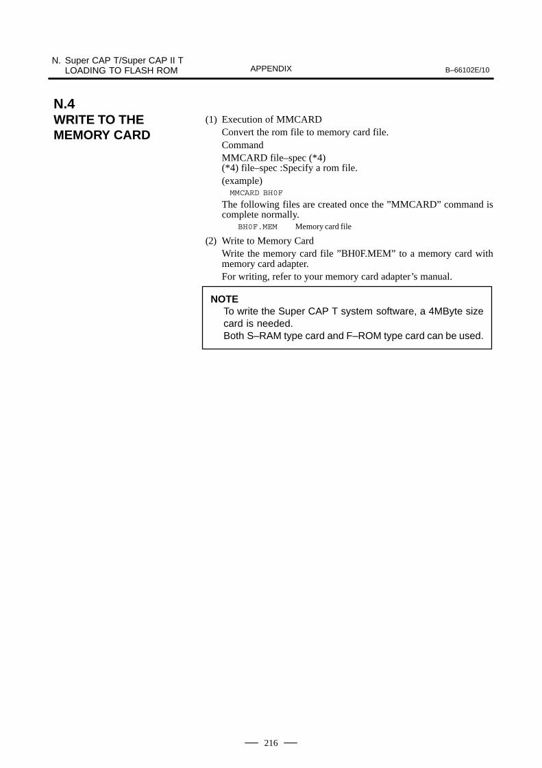
N. Super CAP T/Super CAP II T LOADING TO FLASH ROM B–66102E/10APPENDIX
216
(1) Execution of MMCARDConvert the rom file to memory card file.CommandMMCARD file–spec (*4)(*4) file–spec :Specify a rom file.(example)MMCARD BH0F
The following files are created once the ”MMCARD” command iscomplete normally.
BH0F.MEM Memory card file
(2) Write to Memory CardWrite the memory card file ”BH0F.MEM” to a memory card withmemory card adapter.For writing, refer to your memory card adapter’s manual.
NOTETo write the Super CAP T system software, a 4MByte sizecard is needed.Both S–RAM type card and F–ROM type card can be used.
N.4WRITE TO THEMEMORY CARD
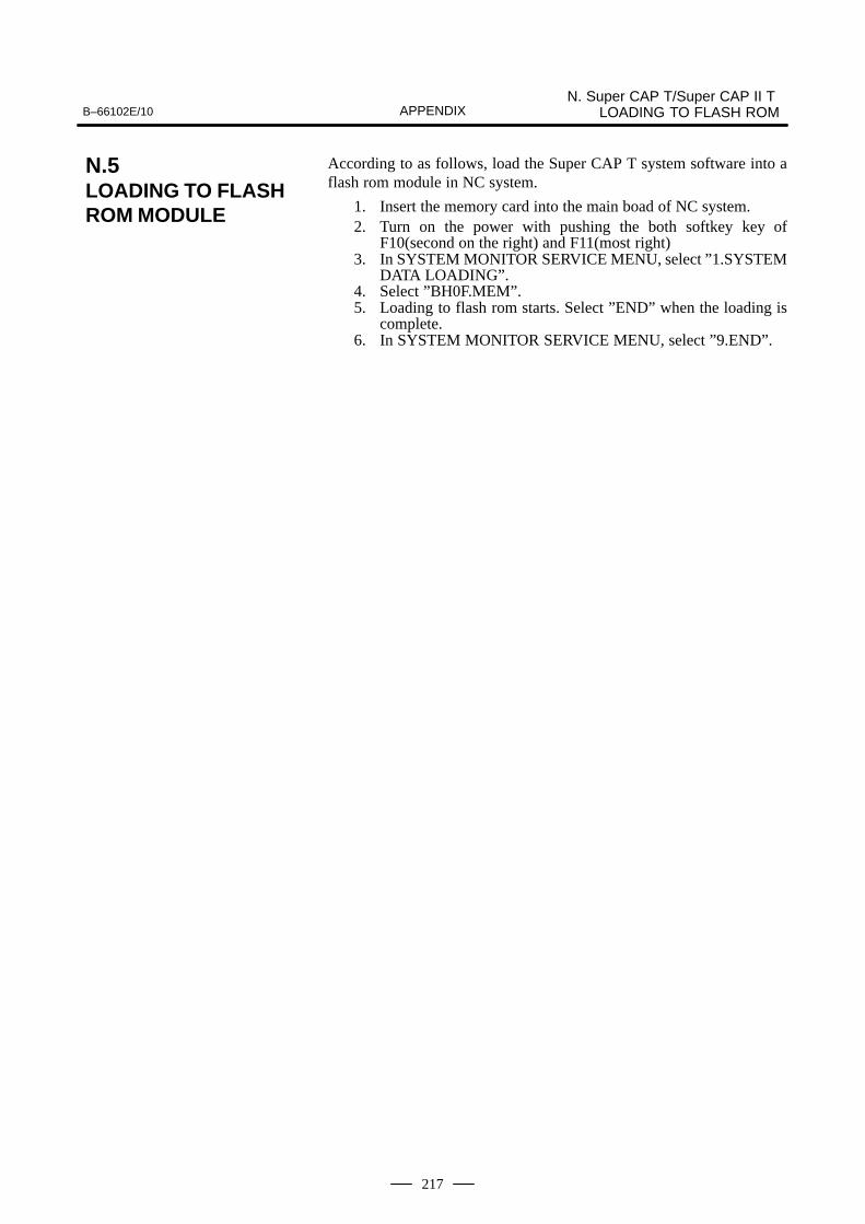
B–66102E/10N. Super CAP T/Super CAP II T
LOADING TO FLASH ROMAPPENDIX
217
According to as follows, load the Super CAP T system software into aflash rom module in NC system.
1. Insert the memory card into the main boad of NC system.2. Turn on the power with pushing the both softkey key of
F10(second on the right) and F11(most right)3. In SYSTEM MONITOR SERVICE MENU, select ”1.SYSTEM
DATA LOADING”.4. Select ”BH0F.MEM”.5. Loading to flash rom starts. Select ”END” when the loading is
complete.6. In SYSTEM MONITOR SERVICE MENU, select ”9.END”.
N.5LOADING TO FLASHROM MODULE


IndexB–66102E/10
i–1
[A]Alarms, 159, 172
[B]Boot Slot Configuration Screen, 124
Boot System (for Series 15–B/15i–A), 173
Boot System (for Series 16–B/C, 18–B/C, 20, 21–B),97
BOOT SYSTEM (For Series 16i/18i/21i), 122
[C]CAP Control Module, 87
Compile Error Code Table, 53
Compile Parameters, 203, 210
Compile/Link Example, 57
Compiler Series, 11
Compiling, 214
Conversion of Table Data with the Macro Linker(Mlink), 83
Conversion to a Memory Card Format (MMCARD)(This Function is Used in the Series15–B/16–B/16–C/18–B/18–C/20/21–B/16 i–A/18i–A/21i–A.), 26
Creating Link Files, 92, 95
Creating Programs, 91, 94
Creating Programs by Using Super Cap II M/SuperCap II T with Series 16i/18i, 84
Creating Sample User Modules for SUPER CAP II M,94
Creating Sample User Modules for SUPER CAP II T,91
[D]Determining the Cause of the No–space State, 120
Developing a User Module, 88
Development Environment, 86
[E]End of Boot System, 114
Equipment Configuration, 5
Error Messages and Required Actions, 115, 140
Executing the User Program, 89
[F]Features, 2
Flash ROM Transfer End Screen (Except Series 21),153
Flash ROM Transfer Screen (Except Series 21), 152
Free Area in Flash Memory (Series 20), 120
Functions, 13
[G]GP–IB Interface Setting (for Sereis 0, 15–A, 16–A,
18–A), 34
[H]How to View Reference List/Compile List, 36
[I]Installing the Executor File from the FAPT MACRO
Library Floppy Disk, 9
Installing the System from the FAPT MACRO Com-piler System Floppy Disk, 7
Introduction, 80
IPL Menu, 161
[L]Link Control File, 83
Link List File, 83
Linking, 215
Load Basic System Function, 139
Loading End Menu, 164
Loading End Screen, 149
Loading Menu, 163
Loading Screen, 148
Loading Start Menu, 163
Loading Start Screen, 147
Loading to Flash ROM Module, 217
[M]Macro Compiler
(MCOMP0/MCOMP15/MCOMP15i), 14

Index B–66102E/10
i–2
Macro Converter (MCONV), 81
Macro Converter (MCONV) Operation Guide for theFANUC Series 16/18 Super Cap M/Super Cap II M,79
Macro Libraries for Developing User Modules, 88
Macro Linker (MLINK), 17
Macro Program Input, 24
Macro Program Output, 24
Memory Card File Delete Screen, 112, 137
Memory Card Format Function, 113, 138
Memory Card Specifications and Restrictions, 175
Menu for end of Transfer of FLASH ROM Memory,167
Menu for Transferring Data into FLASH ROMMemory, 166
[N]Name of Macro Library, 188
Notes, 155, 168
[O]Operation, 81
Operation and Corresponding Screens, 100
Overview, 123
[P]P–CODE LOADER FUNCTION (FOR Series
16–B/C, 18–B/C, 21–TA, Series 16i/18i/21i–A), 143
P–code Loader Function (for Series 20), 160
Parameter, 156, 169
Parameters, 191
Parameters Other than Series 15i, 203
Password, 118
Path Setting, 10
Processing by P–code Loader Function, 145
Processing Flow for the P–code Loader Function, 162
[R]RAM Initialization Screen, 146
RAM Initializing Menu, 162
Registering a Mem–format File, Stored on a MemoryCard, into F–rom, 178
Registering a ROM–format File, Stored on a ROMCassette, into F–ROM, 184
Restrictions and Notes on Developing the User Mod-ule, 89
Restrictions Imposed on the System, 90
Rom Write/Verification Parameter Table, 56
ROM–Format File Transmitter (CNC) (For Series16/18/20/21T–A), 21
ROM–Format File Transmitter (FANUC FA Writer,GP–IB Interface) (for Series 0, 15–A, 16–A, 18–A),25
ROM–Format File Transmitter (FANUC PMC Writer/FANUC FA Writer) (for Series 0, 15–A, 16–A,18–A), 23
RS–232–C Interface Setting, 33
[S]Saving a Mem–format File from F–ROM to a
Memory Card, 182
Screen Configuration and Operating Procedure, 125
Selecting a RS–232–C/GPIB Interface Control System(MDEV), 12
Serial Interface Utility, 24
Series 15i Compile Parameters, 192
Setting a Macro Password (Series 20), 118
Setting a Password, 119
Source File, 81
Specifying a Password for the Series 20 Boot System,119
Specifying a Temporary File Output Destination(MTMP), 12
Specifying Environment Variables, 12
SRAM Data Backup Screen, 110, 134
Starting the Boot System, 98, 123, 176
Starting the P-code Loader Function, 145
Super CAP T/Super CAP II T Loading to Flash ROM,212
Symbolic Macro Program, 27
System Common Symbol Definition(\MCOMP\TOOL\SYSTEM.DEF), 39
System Common Symbol Definition File, 35
System Data Check Screen, 104, 129
System Data Delete Screen, 106, 131
System Data Loading Screen, 101, 126
System Data Save Screen, 108
System File and User File, 99
System Files and User Files, 124
System Installation (Setup), 6, 213
B–66102E/10 Index
i–3
[T]Table Conversion List File, 82
Table Data File, 82
Transferring the User Module to F–ROM, 89
Types of Files in F–ROM, 187
[U]User Modules, 88
[W]Write to the Memory Card, 216


Rev
isio
n R
eco
rd
FAP
T M
AC
RO
CO
MP
ILE
R(F
or
Per
son
al C
om
pu
ter)
PR
OG
RA
MM
ING
MA
NU
AL
(B
–661
02E
)
05Ju
l., 1
995
•A
dditi
on o
f Ser
ies
21–M
B.
•A
dditi
on o
f AP
PE
ND
IX 1
1 B
OO
T S
YS
TE
M (
For
Ser
ies
15–B
).
•C
orre
ctio
n of
err
ors.
10Ju
l., 2
001
Add
ition
of S
erie
s 16
i/18i
/21i
/160
i/180
i/210
i–M
OD
EL
B
04Ja
n., 1
995
•A
dditi
on o
f Ser
ies
21–T
B
•A
dditi
on o
f AP
PE
ND
IX 1
0 D
ATA
INP
UT
/OU
TP
UT
WIT
HM
EM
OR
Y C
AR
DS
(S
YS
TE
M M
ON
ITO
R F
UN
CT
ION
onl
yfo
r S
erie
s 21
–TB
).
09Ju
l., 2
000
Add
ition
of S
erie
s 0i
–MO
DE
L A
03M
ar.,
1994
Add
ition
of S
erie
s 16
–B.
08S
ep.,
1999
Add
ition
of S
erie
s 15
i–M
OD
EL
A
02M
ar.,
1993
Add
ition
of S
erie
s 18
.
Add
ition
of S
erie
s 20
.07
Jul.,
199
7A
dditi
on o
f Ser
ies
16i/1
8i/2
1i/1
60i/1
80i/2
10i–
MO
DE
L A
01Ju
l., 1
991
06Ja
n., 1
997
Add
ition
of S
erie
s 16
/18/
160/
180–
MO
DE
L C
.
Edi
tion
Dat
eC
onte
nts
Edi
tion
Dat
eC
onte
nts


• No part of this manual may bereproduced in any form.
• All specifications and designsare subject to change withoutnotice.