ge energy - lho-ontario.ca driven by ideas.pdf · 500 to 1,100 kw - available as v12, v16 ... ge...
TRANSCRIPT
driven by ideaspower solutions with Jenbacher gas engines
GE Energy
GE imagination at work
GEA
-140
68
© 2
005
GE
Jenb
ache
r G
mbH
& C
o O
HG
. All
right
s re
serv
ed.
gejenbacher.com


overview
company 01
gas as energy source 03Natural gas 04Biogas and special gases 04
products 09Gas engines 10Generator sets 12Cogeneration systems 12Container solutions 12DIA.NE® XT – Dialog Network 13Activated carbon adsorber 14CL.AIR® – Clean Air 15
energy supply 17Decentralized energy supply 18Cogeneration 18Steam production and drying processes 19CO2 fertilization in greenhouses 19Trigeneration 19
service 21On-site in more than 30 countries 22Contact addresses 23
GE imagination at work

company
striving for excellence
1
GE Energy’s gas engine business is one of the world’s leadingmanufacturers of gas-fueled reciprocating engines, packagedgenerator sets and cogeneration units for power generation.It is one of the only companies in the world focusing exclusi-vely on gas engine technology.
Jenbacher engines range in power from 0.25 to 3 MW andrun on either natural gas or a variety of other gases (e.g.,biogas, landfill gas, coal mine gas, sewage gas, combustibleindustrial waste gases). A broad range of commercial, in-dustrial, and municipal customers use Jenbacher productsfor on-site generation of power, heat, and cooling. Patentedcombustion systems, engine controls, and monitoring enable
our power generation plants to meet all relevant internationalemission standards, while offering high levels of efficiency,durability, and reliability.
GE Energy’s Jenbacher product team has its headquarters,production facilities, and 1,000 of its more than 1,250 world-wide employees in Jenbach, Austria.
This brochure provides an overview of the Jenbacher product range, including the variety of possible fuels, their significance as a valuable source of energy, and the advantages of a decentralized energy supply usingJenbacher equipment.
GE Energy’s gas engine business: technology, quality and service

gas as energy source
3
seeing the potential ofnature and chemistry

gas as energy source
biogas and special gasesAlternative energy sources
The biogas and special gases segment is comprised of plants that generate energy from landfills, agriculture, coal mining, chemical plants,and other industries. The environmentally-appropriate disposal of problem gases is the primary concern in this segment. The simultaneousenergetic utilization of these gases for generating power ensures the economic viability of the power plants. The continuous development of its gas engines and the focus on special gas applications have madeJenbacher engines one of the world leaders in this segment today.
Gases with a wide range of calorific values are converted into energy in the process.
Biogas and special gas utilization in gas enginesnumerous advantages
- Highly efficient for power and heat generation (gas is sometimes available as a waste product free of charge)
- Substitute for conventional fuels- Alternative disposal of problem gases- Avoids venting methane (CH4) into the atmosphere- High potential for reduction of greenhouse effects
Overview of the most important applications- Biogas - Landfill gas- Sewage gas - Coal mine gas- Coke gas - Pyrolysis gas/wood gas
54
Biogas
For a wide range of organic substances from agriculture, foodstuff, and feed industries, anaerobic fermentation is a superior alternative tocomposting. Biogas – a mixture of methane and carbon dioxide – is formed in the fermentation process and serves as a high-energy fuel that can substitute fossil fuel energy. Additionally, biogas is characterizedby CO2 neutrality meaning that an increased utilization of fossil fuels isavoided and thereby fossil CO2 emissions are reduced. Using biogas ingas engines promotes proper waste disposal, and also allows for an efficient energy supply with low emissions. Additionally, the end productsfrom the fermentation of the biomass can be utilized as fertilizer.
natural gasEnergy source of the future
The natural gas segment of GE Energy’s gas engine business includes theproduction and delivery of plants for decentralized energy supply basedon natural gas as fuel.
Natural gas utilization in gas engines numerous advantages
Lowest emissions of all fossil fuelsThe utilization of natural gas in gas engines is characterized by thelowest CO2 emission levels among fossil fuels, and particularly low emissions of SO2, NOx and particulate matter.
Most important fossil energy sourceNatural gas plays a major role in energy supply today and will becomethe most significant fossil energy medium in the next 50 years.
Well developed natural gas supply systemThe natural gas supply system is well developed and reliable. Gas enginesare therefore an optimal technology for decentralized energy supply.
Flare gas
In addition to classic natural gas, flare gas also forms part of this fuelsegment. Flare gas is an associated gas obtained during crude oil exploration, largely consisting of methane and higher hydrocarbons. This composition results in a gas with low knocking resistance, whichrequires specially designed engines. The use of flare gas, which is generally available free of charge as a waste product, ensures a fuelsource for power generation and, if required, the engines can also providea heat supply for surrounding facilities. Consequently this problem gascan be eliminated, while being economically and practically utilized.
numerousadvantages Biogas plant Wolfring, Germany
Landfill gas
Landfill gas is created during the decomposition of organic substances in the waste and consists of methane (CH4), carbon dioxide (CO2), andnitrogen (N2). If this gas escapes uncontrolled, it hampers the recultivationof the landfill site. To prevent this and to avoid offensive smells, smouldering fires, or the migration of landfill gas into the water ways, the gas must be continuously extracted under controlled conditions. With a calorific value of approximately 5 kWh/Nm3, landfill gas constitutes a high-value fuel for gas engines and can therefore be economically utilized for power generation.
Landfill site Nent, Hong Kong

Sewage gas
Sewage sludge is created as a waste product in the mechanical, biologicalor chemical cleaning stage of sewage treatment plants. The sludge isdried, then transferred to a digester where an anaerobic fermentationprocess takes place. The fermentation produces biogas – also calledsewage gas – consisting of 60 – 70% methane and 30 – 40% carbon dioxide. This composition makes sewage gas highly suitable for combustion in gas engines. The electrical energy produced by the gasengine can be utilized for the treatment plant as well as for feeding intothe public power grid. The thermal energy can be used for heating thesewage sludge or to offset the treatment plant’s other heat requirements.
Coal mine gas
Coal mine gas (firedamp) is a problematic phenomenon associated with pitcoal mining, as the gas can form explosive mixtures together with air. Themain component of coal mine gas is methane (25 – 60%), which developsduring the geochemical conversion of organic substances into coal (carbonization). Coal mine gas is present both as liberated gas in fissures,faults and pores, and as adsorbed gas on the inner surface of the coaland neighboring rock. Combustion of coal mine gas in gas engines ispractical as an environmental and safety problem is effectively resolved,while an otherwise lost source of energy is economically utilized.
Pyrolysis gas/wood gasgases from gasification processes
The production of special gases through various gasification processes is becoming increasingly important for the utilization of alternative energy sources. Various base materials (e.g., domestic and commercialwaste, light shredder fractions, bulk waste, wood, meat and bone meal,old tires) are subjected to high-temperature gasification processes, suchas fixed bed, fluidized bed, or pyrolytic gasification. The resultant gasesrequire a highly sophisticated gas engine since their composition usually changes very rapidly. Depending on the gasification process, the combustible components mainly consist of hydrogen, carbon monoxideand methane, having a calorific value in the range from 1.5 to 3.5 kWh/Nm3.Sophisticated gas treatment, rapid reaction to changing calorific values,accurate monitoring of the combustion process in the engine, and effective system coordination between the engine and gasifier, are onlysome of the complex requirements for gas engines using such fuels.
gas as energy source
76
Sewage treatment plant Annacis Island, Canada Colliery Tahmoor, Australia Biomass power station Guessing, Austria
Coke gas
Coke gas is a by-product of coke production from pit coal. Coke gas consists mainly of hydrogen (50 – 60%), methane (15 – 30%) and carbonmonoxide (10 – 20%). Due to the extremely high hydrogen content of cokegas, specially modified Jenbacher gas engines are used to generatepower from this fuel source.
Coke production Profusa, Spain

9
products
finding the right solutions
gas engines Core competence
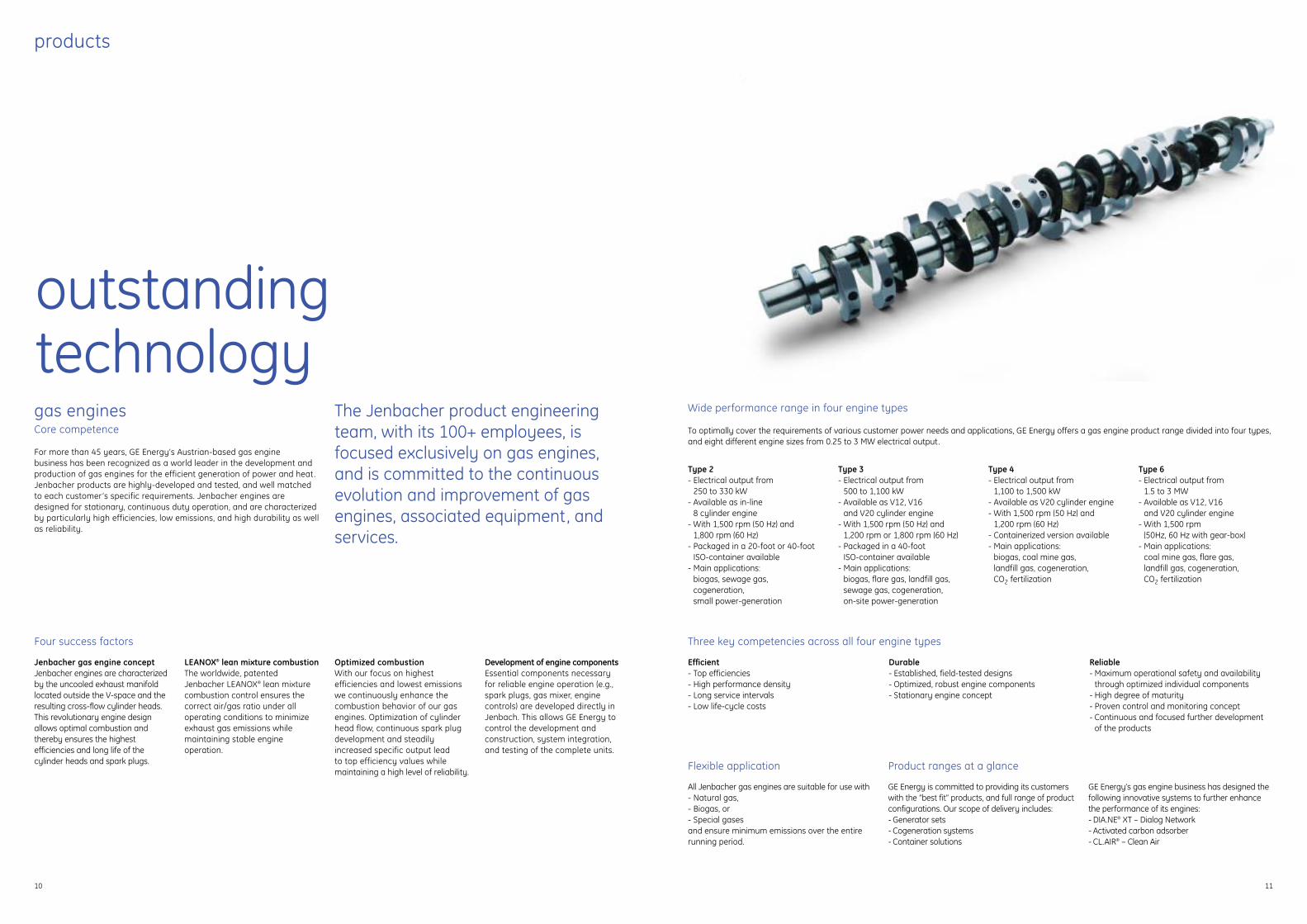
For more than 45 years, GE Energy’s Austrian-based gas engine business has been recognized as a world leader in the development and production of gas engines for the efficient generation of power and heat.Jenbacher products are highly-developed and tested, and well matchedto each customer’s specific requirements. Jenbacher engines are designed for stationary, continuous duty operation, and are characterizedby particularly high efficiencies, low emissions, and high durability as wellas reliability.
Four success factors
Jenbacher gas engine conceptJenbacher engines are characterizedby the uncooled exhaust manifoldlocated outside the V-space and theresulting cross-flow cylinder heads.This revolutionary engine designallows optimal combustion and thereby ensures the highest efficiencies and long life of the cylinder heads and spark plugs.
LEANOX® lean mixture combustionThe worldwide, patentedJenbacher LEANOX® lean mixturecombustion control ensures thecorrect air/gas ratio under all operating conditions to minimizeexhaust gas emissions while maintaining stable engine operation.
Optimized combustionWith our focus on highest efficiencies and lowest emissionswe continuously enhance thecombustion behavior of our gasengines. Optimization of cylinderhead flow, continuous spark plugdevelopment and steadily increased specific output lead to top efficiency values whilemaintaining a high level of reliability.
Development of engine componentsEssential components necessaryfor reliable engine operation (e.g.,spark plugs, gas mixer, enginecontrols) are developed directly inJenbach. This allows GE Energy tocontrol the development and construction, system integration,and testing of the complete units.
The Jenbacher product engineeringteam, with its 100+ employees, isfocused exclusively on gas engines,and is committed to the continuous evolution and improvement of gasengines, associated equipment, andservices.
Wide performance range in four engine types
To optimally cover the requirements of various customer power needs and applications, GE Energy offers a gas engine product range divided into four types,and eight different engine sizes from 0.25 to 3 MW electrical output.
Three key competencies across all four engine types
Efficient- Top efficiencies- High performance density- Long service intervals- Low life-cycle costs
Durable- Established, field-tested designs- Optimized, robust engine components- Stationary engine concept
Reliable- Maximum operational safety and availability
through optimized individual components- High degree of maturity- Proven control and monitoring concept- Continuous and focused further development
of the products
Flexible application
All Jenbacher gas engines are suitable for use with- Natural gas,- Biogas, or- Special gasesand ensure minimum emissions over the entirerunning period.
Product ranges at a glance
GE Energy is committed to providing its customerswith the “best fit” products, and full range of productconfigurations. Our scope of delivery includes:- Generator sets- Cogeneration systems- Container solutions
GE Energy’s gas engine business has designed thefollowing innovative systems to further enhancethe performance of its engines:- DIA.NE® XT – Dialog Network- Activated carbon adsorber- CL.AIR® – Clean Air
products
1110
outstanding technology
Type 2- Electrical output from
250 to 330 kW- Available as in-line
8 cylinder engine- With 1,500 rpm (50 Hz) and
1,800 rpm (60 Hz)- Packaged in a 20-foot or 40-foot
ISO-container available- Main applications:
biogas, sewage gas, cogeneration, small power-generation
Type 3- Electrical output from
500 to 1,100 kW- Available as V12, V16
and V20 cylinder engine- With 1,500 rpm (50 Hz) and
1,200 rpm or 1,800 rpm (60 Hz)- Packaged in a 40-foot
ISO-container available- Main applications:
biogas, flare gas, landfill gas,sewage gas, cogeneration, on-site power-generation
Type 4- Electrical output from
1,100 to 1,500 kW- Available as V20 cylinder engine- With 1,500 rpm (50 Hz) and
1,200 rpm (60 Hz)- Containerized version available- Main applications:
biogas, coal mine gas, landfill gas, cogeneration, CO2 fertilization
Type 6- Electrical output from
1.5 to 3 MW- Available as V12, V16
and V20 cylinder engine- With 1,500 rpm
(50Hz, 60 Hz with gear-box)- Main applications:
coal mine gas, flare gas, landfill gas, cogeneration, CO2 fertilization
products
1312
generator setsMaximum efficiency in power generation
Generator sets provide on-site power generation on demand. Throughtheir decentralized installation and potential for combined power, heatand/or cooling it is possible to avoid distribution losses and increase overall energy efficiency. Jenbacher generator sets are characterized by a compact design and high power density, and therefore require acomparatively small footprint . The engine and generator are mounted on a frame that is vibration-dampened by means of durable elastomerelements. In the same manner, the frame is also insulated from the foundation, preventing any vibration from affecting the building. The only requirement is that the generator set foundation is within a certain evenness.
cogeneration systemsCombined generation of power and heat
Cogeneration systems generate power and heat where required, providingmaximum efficiency in the conversion of energy with minimum emissions.Their basic structure corresponds to that of the generator sets – with theaddition of heat exchangers for utilizing the waste heat. A wide range ofengine heat sources – from engine cooling water, oil and air/fuel gas mixture to exhaust gas – is configured to maximize the benefit to eachindividual customer.
The highly compact design and the efficient elastic mounting ofJenbacher cogeneration systems require little in terms of space andfoundation design so that the peripheral installation costs are minimal.
container solutions Maximum flexibility
The scope of delivery for Jenbacher engines includes fully containerized plants, requiring only gas and power connections on location for operation.All plant components required for operating the set are integrated in the container and on the container roof. The electrical control and switching system is located in a separated compartment of the container, providing for comfortable operation of the plant. The overall compact design ensuresa space-saving installation with service oriented accessibility.
With this flexible container design our customers’ requirements can easily be met.
DIA.NE® XT – Dialog NetworkOptimum control
DIA.NE® XT is the latest Jenbacher engine management system, and isdesigned for use with all Jenbacher engines. The system comprisespowerful central industrial controls that handle master control and feedback control for the engine-plant , as well as visualization. A link, via standardized industry buses or using direct signal lines, with centralprocess control is provided to meet the specific requirements of eachcustomer.
The focus of the DIA.NE® XT design lies in combining powerful and flexible open- and closed-loop control electronics with a user-friendlyoperating concept. The novel hardware design employs the most moderncomponents and sets new standards for performance, functionality andoperating safety. The visual display uses a color graphics display screen,providing a clear and comprehensible presentation of information andmeasured values while offering the greatest possible ease of use.
With additional components it is possible to adapt DIA.NE® XT individually to meet various customer requirements:
MONICMonitoring Ignition Control: On-line monitoring system of the ignition voltage that allowspreventive maintenance of sparkplugs and ignition coils.
HERMESData remote transmission: HERMES offers the operator remote diagnostics and solutionsat any time via internet , modemor LAN connection.
HERMES provides the followingtwo applications, which can beused separately or together:
DIA.NE® WINDialog Network for WindowsSystems: Delivers full remote operation of Jenbacher engines as well as comprehensive functions for analysis and trendidentification in the familiarWindows environment.
DIA.NE® RMCDialog Network for RemoteMessage Control: Automated dataand message transmission to aremote data transmission centerand auto-alarm by way of fax,SMS and/or e-mail. All incomingmessages and data are archivedfor maximum traceability of operations.
advancedsolutions
CL.AIR® – Clean AirExhaust gas treatment for cleaner air
If fuel gases such as landfill gas or sewage gas are used, the harmfulcontaminants in the gas may inhibit the performance of the oxidizingcatalytic converters. With the CL.AIR® system, we utilize thermal re-combustion to maintain minimum CO, HC and formaldehyde limitvalues. In so doing, the engine can be operated with both maximum specific power and maximum efficiency.
In detai :
The exhaust gas flows over a hot ceramic storagemass where the gas is heated to approximately800°C. Uncombusted components of the exhaust gas (e.g., CO, or HC) are recombusted at this hightemperature. The exhaust gases then flow over asecond, cooler storage mass, which is heated in theprocess. Through a change-over mechanism, alternately passing the exhaust gas over the two storage masses, the energy requirement is minimizedso that system-related thermal losses can be largelycompensated.
activated carbon adsorberLonger service life through fuel gas cleaning
Sewage gas and landfill gas frequently contain gaseous silicon compounds.For cleaning the fuel gas from these substances, we have developed an activated carbon adsorber system.
The system prevents the formation of silica in the engine, increasingcomponent service lives and reducing engine wear. Gas cleaning alsoextends oil life and enables – under certain conditions – the use of conventional oxidizing catalytic converters for the reduction of CO andformaldehyde emissions. As a result , the Jenbacher activated carbonadsorber allows reliable, durable, highly efficient , and low emission operation with sewage gas and landfill gas.
Especially for landfill applications and plants with larger output range inremote areas, we have developed the TSA (Temperature Swing Adsorber),which is a regenerative system. The advantage of this new technology isthat the activated carbon regenerates itself, which ensures continuousoperation over longer periods of time without the need to change theactivated carbon.
In detail:
Fuel gas is passed through a vessel filled with activated carbon where certain gaseous compounds(mainly silicon and halogen) are adsorbed by theactivated carbon. The degree of saturation of theactivated carbon is regularly checked and replacedwhen the prescribed maximum limit has been reached.For landfill gas plants, GE Energy provides the automaticself-regenerating TSA system where the replacement ofthe activated carbon is only necessary at very longintervals.
products
1514
fresh air

energy supply
expanding boundaries
17
energy supply
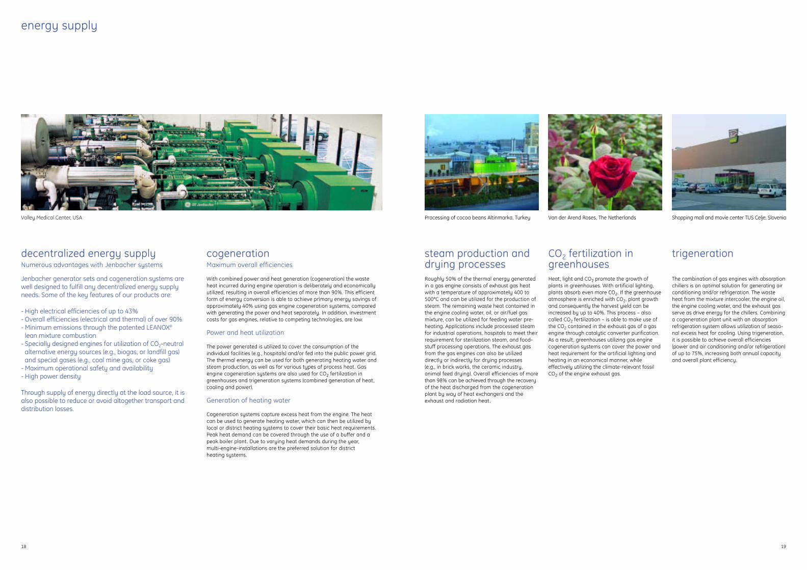
cogenerationMaximum overall efficiencies
With combined power and heat generation (cogeneration) the waste heat incurred during engine operation is deliberately and economicallyutilized, resulting in overall efficiencies of more than 90%. This efficientform of energy conversion is able to achieve primary energy savings ofapproximately 40% using gas engine cogeneration systems, comparedwith generating the power and heat separately. In addition, investmentcosts for gas engines, relative to competing technologies, are low.
Power and heat utilization
The power generated is utilized to cover the consumption of the individual facilities (e.g., hospitals) and/or fed into the public power grid.The thermal energy can be used for both generating heating water andsteam production, as well as for various types of process heat. Gas engine cogeneration systems are also used for CO2 fertilization in greenhouses and trigeneration systems (combined generation of heat,cooling and power).
Generation of heating water
Cogeneration systems capture excess heat from the engine. The heat can be used to generate heating water, which can then be utilized bylocal or district heating systems to cover their basic heat requirements.Peak heat demand can be covered through the use of a buffer and apeak boiler plant . Due to varying heat demands during the year, multi-engine-installations are the preferred solution for district heating systems.
steam production anddrying processesRoughly 50% of the thermal energy generatedin a gas engine consists of exhaust gas heatwith a temperature of approximately 400 to500°C and can be utilized for the production ofsteam. The remaining waste heat contained inthe engine cooling water, oil, or air/fuel gasmixture, can be utilized for feeding water pre-heating. Applications include processed steamfor industrial operations, hospitals to meet theirrequirement for sterilization steam, and food-stuff processing operations. The exhaust gasfrom the gas engines can also be utilizeddirectly or indirectly for drying processes (e.g., in brick works, the ceramic industry, animal feed drying). Overall efficiencies of morethan 98% can be achieved through the recoveryof the heat discharged from the cogenerationplant by way of heat exchangers and theexhaust and radiation heat.
CO2 fertilization ingreenhousesHeat, light and CO2 promote the growth ofplants in greenhouses. With artificial lighting,plants absorb even more CO2. If the greenhouseatmosphere is enriched with CO2, plant growthand consequently the harvest yield can beincreased by up to 40%. This process – also called CO2 fertilization – is able to make use ofthe CO2 contained in the exhaust gas of a gasengine through catalytic converter purification.As a result , greenhouses utilizing gas enginecogeneration systems can cover the power andheat requirement for the artificial lighting andheating in an economical manner, while effectively utilizing the climate-relevant fossilCO2 of the engine exhaust gas.
trigeneration
The combination of gas engines with absorptionchillers is an optimal solution for generating airconditioning and/or refrigeration. The wasteheat from the mixture intercooler, the engine oil,the engine cooling water, and the exhaust gasserve as drive energy for the chillers. Combininga cogeneration plant unit with an absorptionrefrigeration system allows utilization of seaso-nal excess heat for cooling. Using trigeneration,it is possible to achieve overall efficiencies(power and air conditioning and/or refrigeration)of up to 75%, increasing both annual capacityand overall plant efficiency.
1918
decentralized energy supplyNumerous advantages with Jenbacher systems
Jenbacher generator sets and cogeneration systems are well designed to fulfill any decentralized energy supplyneeds. Some of the key features of our products are:
- High electrical efficiencies of up to 43%- Overall efficiencies (electrical and thermal) of over 90%- Minimum emissions through the patented LEANOX®
lean mixture combustion- Specially designed engines for utilization of CO2-neutral
alternative energy sources (e.g., biogas, or landfill gas) and special gases (e.g., coal mine gas, or coke gas)
- Maximum operational safety and availability- High power density
Through supply of energy directly at the load source, it isalso possible to reduce or avoid altogether transport and distribution losses.
Processing of cocoa beans Altinmarka, Turkey Van der Arend Roses, The Netherlands Shopping mall and movie center TUS Celje, SloveniaValley Medical Center, USA

service
for your reliability
21
On the way to the top you better have a strong partner.

on-site in more than 30 countriesThe Jenbacher product team’s commitment to the customer goes beyond designing the best available technology. Our success is measured by our customers’long term satisfaction with the performance of our equipment. The main concern in this regard is to offer customers the full range of services needed to ensure aconvenient and efficient energy supply and special gasdisposal from one source.
Service contracts
With customized service contracts GE Energy ensures the best possiblefulfillment of individual customer requirements.
Worldwide service organization
Jenbacher service technicians and external service providers are locatedin more than 30 countries. This service network secures the optimum careand support of our customers.
Remote diagnosis and remote servicing
The in-house Jenbacher Competence Center makes use of remote diagnosis and remote servicing by means of HERMES, the data remotetransfer system developed in-house, and networked worldwide by satellite. The Competence Center is run by a team of experienced andhighly-qualified commissioning service engineers in Jenbach and ensurestimely and accurate technical support .
Training Center
The Jenbacher Training Center, located in Jenbach, offers specific participant-oriented training courses for customers, operators and salesand service providers. Hands-on training programs are offered either atthe customer site or at the Training Center.
service
22
Gas engine manufacturing building at the Austrian Headquarters

for more information on Jenbacher gas engines
Austria (Headquarters)Achenseestraße 1-3A-6200 JenbachT +43 5244 600-0 F +43 5244 [email protected]
DenmarkIndustrivej 19DK-8881 ThorsøT +45 86966788 F +45 [email protected]
GermanyAmselstraße 28D-68307 MannheimT +49 621 77094-0 F +49 621 [email protected]
China15 Floor, The Lee Gardens33 Hysan Avenue Causeway BayHong KongT +852 2100 6976 F +852 2100 [email protected]
ItalyVia Crocioni, 46/H, Casella Postale n. 41 ApertaI-37012 Bussolengo (VR)T +39 045 6760211F +39 045 [email protected]
Spain and PortugalAvda. del Camino de lo Cortao, 34 – Nave 8E-28700 San Sebastián de los Reyes (Madrid)T +34 916586800 F +34 [email protected]
The NetherlandsStationspark 750NL-3364 DA SliedrechtT +31 184 495222 F +31 184 [email protected]
United Arab EmiratesCity Tower II, Sheikh Zayed RoadP.O. Box 11549, DubaiT +971 4 3131486F +971 4 [email protected]
USA15855 Jacinto Port Blvd Houston, TX 77015 T +1 281 8642765 F +1 281 8642506 [email protected]
GE imagination at work

driven by ideaspower solutions with Jenbacher gas engines
GE Energy
GE imagination at work
GEA
-140
68
© 2
005
GE
Jenb
ache
r G
mbH
& C
o O
HG
. All
right
s re
serv
ed.
gejenbacher.com