ge consumer & industrial multilin dtr · 6.1 mechanical construction 66 ... dtr units are...
TRANSCRIPT

GE Multilin215 Anderson AvenueL6E 1B3 Markham, ON -CANADAT (905) 294 6222 F (905) 294 8512E [email protected]
Internet: www.GEMultilin.com
Copyright © 2005 GE Multilin
DTRDigital Tap Changer Controller
Instruction ManualGEK-106305A
GE MultilinAvda. Pinoa, 1048170 Zamudio SPAINT +34 94 485 88 00 F +34 94 485 88 45E [email protected]
g GE Consumer & IndustrialMultilin

TABLE OF CONTENTS
GEK-106305A DTR Digital Tap Changer Controller 1
TABLE OF CONTENTS
1. GENERAL DESCRIPTION AND APPLICATION 5
2. OPERATION PRINCIPLES 8 2.1 CONTROL FUNCTIONS 8 2.1.1 REGULATION ALGORITHMS .......................................................................................................................8 2.1.2 OPERATING CURVE...................................................................................................................................11 2.1.3 REGULATION AUTOMATISM .....................................................................................................................12 2.1.4 EXCESSIVE OPERATIONS BLOCK. ..........................................................................................................15 2.1.5 SUCCESSIVE OPERATIONS IN A CERTAIN TIME FRAME BLOCK ........................................................15 2.1.6 OVERVOLTAGE, UNDERVOLTAGE AND OVERCURRENT BLOCKS. ....................................................15 2.1.7 QUICK LOWERING FUNCTION..................................................................................................................15 2.2 MONITORING AND REGISTER FUNCTIONS 16 2.2.1 MEASUREMENTS .......................................................................................................................................16 2.2.2 COUNTERS .................................................................................................................................................17 2.2.3 INTERNAL STATUS.....................................................................................................................................18 2.2.4 SELF-CHECKING FUNCTIONS ..................................................................................................................28 2.3 ANALYSIS FUNCTIONS 29 2.3.1 EVENT REGISTER ......................................................................................................................................29 2.4 CONTROL FUNCTIONS 29 2.4.1 ALARMS TREATMENT................................................................................................................................29 2.4.2 SIGNALING ..................................................................................................................................................31 2.4.3 COMMANDS ................................................................................................................................................31 2.4.4 TIME SYNCHRONIZATION .........................................................................................................................31 2.4.5 CONFIGURABLE INPUTS AND OUTPUTS................................................................................................32 2.4.6 SETTING TABLES .......................................................................................................................................34 2.5 USER INTERFACE AND COMMUNICATIONS 35 2.5.1 LOCAL USER INTERFACE .........................................................................................................................35 2.5.2 REMOTE COMMUNICATIONS. SOFTWARE.............................................................................................38
3. SETTINGS 42 3.1 SETTINGS 42 3.2 COMMENTS ABOUT THE SETTINGS 45 3.2.1 GENERAL SETTINGS .................................................................................................................................45 3.2.2 X1.REGULATION SETTINGS......................................................................................................................47 3.2.3 X2. BLOCK SETTINGS...............................................................................................................................48 3.2.4 X3. TIMERS..................................................................................................................................................48 3.2.5 X4. VOLTAGE SETPOINT ...........................................................................................................................49
4. PROGRAMMING THE UNIT 50 4.1 INPUT CONFIGURATION 50 4.2 OUTPUT CONFIGURATION 53 4.3 GRAPHIC DISPLAY CONFIGURATION 53 4.4 MAIN SCREEN 54 4.5 ALARMS SCREEN 56 4.6 MEASURES SCREEN 58 4.7 INPUTS/OUTPUTS SCREEN 58
5. TECHNICAL CHARACTERISTICS 60 5.1 MODEL LIST 60 5.2 TECHNICAL CHARACTERISTICS 61

TABLE OF CONTENTS
2 DTR Digital Tap Changer Controller GE—106305A
6. HARDWARE DESCRIPTION 65 6.1 MECHANICAL CONSTRUCTION 66 6.1.1 BOX CONSTRUCTION................................................................................................................................ 66 6.1.2 ELECTRICAL CONNECTIONS. .................................................................................................................. 66 6.1.3 INTERNAL CONSTRUCTION. .................................................................................................................... 67 6.1.4 IDENTIFICATION......................................................................................................................................... 68 6.1.5 MAGNETIC MODULE.................................................................................................................................. 68 6.1.6 PROTECTION CPU PROCESSING BOARD.............................................................................................. 69 6.1.7 CPU COMMUNICATIONS BOARD. ............................................................................................................ 69 6.1.8 DIGITAL INPUTS BOARD. .......................................................................................................................... 69 6.1.9 DIGITAL OUTPUTS BOARD ....................................................................................................................... 70 6.1.10 POWER SUPPLY ........................................................................................................................................ 70 6.2 RECEPTION, HANDLING & STORAGE 71 6.3 INSTALLATION 71
7. ACCEPTANCE TESTS 73 7.1 VISUAL INSPECTION 73 7.2 INSULATION TEST 73 7.3 POWER SUPPLY 73 7.4 METERING 74 7.5 VERIFICATION OF INPUTS 74 7.6 COMMUNICATIONS 75 7.7 DISPLAY, KEYPAD AND LEDS. 75 7.8 VERIFICATION OF OUTPUTS, AND DTR OPERATION 76 7.8.1 VERIFICATION OF ALARM CONTACTS; LOCAL AND REMOTE: ........................................................... 76 7.8.2 VERIFICATION OF RTU OUTPUTS: .......................................................................................................... 77 7.8.3 VERIFICATION OF THE TAP-UP/TAP-DOWN COMMANDS OPERATION:............................................. 77 7.8.4 VERIFICATION OF UNDERVOLTAGE, OVERVOLTAGE, AND OVERCURRENT CONTACTS.............. 78 7.9 DYNAMIC VERIFICATION OF THE REGULATOR OPERATION 78 7.9.1 VERIFICATION OF THE “NUMBER OF OPERATIONS”............................................................................ 79 7.9.2 VERIFICATION OF THE NUMBER OF “SUCCESSIVE OPERATIONS” ................................................... 80
8. INSTALLATION AND MAINTENANCE 82 8.1 INSTALLATION 82 8.2 CONNECTION TO GROUND AND SUPPRESSION OF DISTURBANCES 82 8.3 MAINTENANCE 82
9. KEYPAD AND DISPLAY 85 9.1 MENU TREE 86 9.2 SETTINGS GROUP 88 9.3 INFORMATION GROUP 92 9.4 OPERATIONS GROUP 94 9.5 SINGLE-KEY OPERATION. 95 9.6 CONFIGURATION MENU 96

TABLE OF CONTENTS
GEK-106305A DTR Digital Tap Changer Controller 3
LIST OF TABLES
Table I : Internal communications statuses
Table II : Internal protection statuses
Table III : Settings common to all tables
Table IV : Independent settings for each table
LIST OF FIGURES
Fig. 1 : Wiring diagram for DTR units with taps coded in BCD
Fig. 2 : Wiring diagram for DTR units with taps per contact
Fig. 3 : Panel mounting diagram
Fig. 4 : RS-232 connection
Fig. 5 : Dimensions diagram
Fig. 6 : Front view
Fig. 7 : Rear view

TABLE OF CONTENTS
4 DTR Digital Tap Changer Controller GE—106305A

1. GENERAL DESCRIPTION AND APPLICATION
GEK-106305A DTR Digital Tap Changer Controller 5
1. GENERAL DESCRIPTION AND APPLICATION
New technologies have allowed in the last years a significant development in the integration of functions performed by the different components of a power system. The reason for this integration is the bigger need for reducing and optimizing the investments in equipment and installations, as well as the management and use of energy, due to the significant savings involved.
This integration of functions includes not only the switchgear control devices for high and low voltage, protection for the different elements, signaling and alarms in a substation, but also the monitoring of all elements, the analysis of the available information (events, alarms, oscillography, load/demand profiles, etc.), and certain innovative functions such as the substation maintenance, adaptive protections, etc.
DTR units are microprocessor based relays used for the voltage control in the power system.
DTR is used in MV substations for controlling the voltage, operating on the OLTC of power transformers.
The functions integrated in these units are:
A) CONTROL:
• Transformer OLTC control
• Overvoltage unit for monitoring the OLTC control
• Undervoltage unit for monitoring the OLTC control
• Overcurrent unit for monitoring the OLTC control
• Blocking functions for excessive number of operations (totals) and for excessive number of successive operations in a determined period of time.
• Fast backward function, if the difference to the setpoint is excessive.
B) MONITORING AND REGISTER
• Metering and display of the phase current
• Metering and display of voltage
• Metering and display of frequency
• Display of the tap value. The device accepts the tap status coded in BCD or in contact per tap (please refer to model list)
• Metering and display of active power
• Metering and display of reactive power
• Metering and display of the power factor
• Metering and display of the voltage difference with respect to the setpoint.
• Display of the operation time
• Programmable graphic display showing the main statuses and measures
• Self check of the unit
• Counter for number of tap-ups, tap-downs and operations
1. GENERAL DESCRIPTION AND APPLICATION
6 DTR Digital Tap Changer Controller GE—106305A
C) ANALYSIS
• Event record
• Alarm record
D) INTERFACES AND COMMUNICATIONS DTR units incorporate two communications ports. The front port is RS232, while the rear port is selectable between RS232, RS485, plastic or glass fiber optic.
The associated software for DTR units is as follows :
• GE-LOCAL communications software, which allows the user to view and modify protection settings, alarms, internal status, etc.
• GE-INTRO configuration software, which allows to program inputs, outputs, alarms and LEDs.
These software packages are part of the GE-NESIS network substation integration system.

2. OPERATION PRINCIPLES
GEK-106305A DTR Digital Tap Changer Controller 7
2. OPERATION PRINCIPLES
2.1 CONTROL FUNCTIONS The transformer tap changer controller controls manually or automatically the OLTC (transformer on load tap changer), originating tap-up and tap-down commands, in order to keep the power supply voltage practically constant, independently from the load.
2.1.1 REGULATION ALGORITHMS
In order to achieve this voltage regulation, the DTR uses two algorithms:
1. Comparing the measured voltage with the voltage setpoint.
2. Compensating the voltage dropouts generated by the load current by means of the calculation of the apparent current. This calculation consists of subtracting from the measured voltage, a voltage proportional to the load current, before the measured voltage is compared with the voltage setpoint.
The main characteristics of both algorithms are:
• The variation of the measured voltage in relation to the voltage setpoint is provided with an Insensibility Degree (ID). This ID is defined as the maximum admissible variation of the voltage before the DTR originates a command to change the tap in the OLTC. This operation avoids the excessive wear of the OLTC contacts, with a practically constant voltage at the same time.
• If the difference between the measured voltage and the setpoint is greater than the Insensitivity Degree will be corrected with a certain delay Operating Time (OT), so that:
• If the difference lasts only for a short time (less than the Operation Time), the DTR system will not order a tap change.
• The voltage deviations will be regulated proportionally to the difference between the real value and the setpoint value. The greater the deviation is, the sooner the DTR will operate.
The way of operation of both algorithms is the following:
1. If |DV| > ID
Absolute value of the difference between the setpoint and the real voltage is greater than Insensitivity Degree
Then An operation on the OLTC must be performed.
Otherwise
No operation will be produced on the OLTC
2. If DV: Deviation between the real voltage and the setpoint is lower than zero
Then
There will be a tap-down operation
Otherwise
There will be a tap-up operation

2. OPERATION PRINCIPLES
8 DTR Digital Tap Changer Controller GE—106305A
The Operation Time to initiate a tap change will be calculated in the following way:
Tb = 10 * ID / |DV| tb==Base Time OT = FT * tb
The user can set the Time Factor (FT) and DV is the deviation between the real voltage and the setpoint calculated in the following way (depending on the selected algorithm)
Algorithm 1: Voltage regulation: DV = V0 - Vm
V0: setpoint, Vm: Measured voltage
Algorithm 2: Compensating by means of the calculation of apparent current: DV = (V0 + Vcom) - Vm V0=setpoint, Vm= Measured voltage
Vcom = Kcom * Im / In
Kcom==Calculation of current (Adjustable)
Im=Measured current, In=Nominal current
Only when Vcom < Vcomax
Otherwise
Vcom = Vcomax
Vcomax==Maximum voltage increase (Adjustable).

2. OPERATION PRINCIPLES
GEK-106305A DTR Digital Tap Changer Controller 9
2.1.2 OPERATING CURVE
The standard operation times (FT=1) for different values of Insensitivity Degree are shown in the following figure:
0 1 2 3 4 5 6 7 8 9 100
1
2
3
4
5
6
7
8
9
10 0.5% 1% 2% 3% 4% 5%
GI[%] == Insensitivity Degree in %
|DU[%]| == Voltage Deviation in %
tb[s
g] =
= Ba
se T
iem
in s
econ
ds

2. OPERATION PRINCIPLES
10 DTR Digital Tap Changer Controller GE—106305A
2.1.3 REGULATION AUTOMATISM
The following status diagram shows the behaviour of the voltage regulation automatism:
Automatic
Timing
Lowering
Stopped
WaitingLower
Manual
Raising
Waiting Raise
Success Raisi
Failed Raising
Failed Lowering
Successful Lowering
Rai
sing
tap
com
man
d
Tim
eOut
& D
V>0
Tim
eOut
Tim
eOut
Stop command
Automatic command
Auto
mat
ic c
omm
and
Man
ual c
omm
and
Stop
com
mad
Lowering Tap command
Man
ual c
omm
and
GI/DV>1+
Interlock+
Sucessive Op.+
27+59+50
Reg. Alarm + Excessive OP. + Irregular Tap Change
Reg. Alarm + Excessive Op. + Irregular Tap Changer
TimeOut & DV<0
Tap(n) - Tap(n-1) = 1 Tap(n) - Tap(n-1) <> 1 Tap(n) - Tap(n-1) <> -1
Tim
eout
+ Tim
eOut
+
Automatic
ManualAutomatic*Automatic*
Manual* Manual*
GI/D
V<1
Stop
com
man
d
Tap(n) - Tap(n-1) = -1
TimeOut & DV>0 & Min Tap + TimeOut & DV<0 & Max Tap

2. OPERATION PRINCIPLES
GEK-106305A DTR Digital Tap Changer Controller 11
The steady statuses of the automatism are the following:
1. Stopped: DTR reaches this state by means of a Stop command and it can only leave this state by means of a Manual command or an Automatic command.
2. Automatic: DTR reaches this state by means of an Automatic command.
In this status, DTR system is always checking if the necessary conditions exist, to initiate a OLTC operation. When these conditions exist, a timer is started and the DTR reaches the Timing Operation Status.
3. Manual: The DTR system reaches this status by means of a Manual command or when it is in Automatic mode and there is an anomalous situation such as Irregular Tap Change, Regulator Alarm, Failed Tap-up/tap-down, etc. In this state the DTR system is waiting for Tap-up, Tap-down, Automatic or Stop commands.
4. Timing Operation: In this status, the DTR system is checking the operation conditions and counting the Operating Time. If the operation conditions disappear, the DTR returns to Automatic state, and if the Operation Time is exceeded, the DTR system changes to Tap-up/ Tap-down status.
5. Tap-Up: When the DTR system is in this state, it checks whether the OLTC is in the maximum tap; if so, then the DTR system stops the operation. Otherwise, the DTR stays in this state during the time set for Operation Pulse before changing to Waiting for Tap-up state.
6. Tap-Down: When the DTR system is in this state, it checks whether the OLTC is in the minimum tap; if so, then the DTR system stops the operation. Otherwise, the DTR stays in this state during the time set for Operation Pulse before changing to Waiting for Tap-Down state.
7. Waiting for Tap-up: In this state, the DTR system waits for the change in the OLTC. If the Success Time finishes its count and the tap change has been successful (OLTC has raised the tap) then the DTR changes to Successful Tap-up state, if not, the DTR changes to Failed Tap-up.
8. Waiting for Tap-down: In this state, the DTR system waits for the change in the OLTC. If the Success Time finishes its count and the tap change has been successful (OLTC has lowered the tap) then the DTR changes its status to Successful Tap-down; if not, the DTR changes to Failed Tap-Down state.
9. Successful Tap-Up: This state shows that the tap increase operation has been successful. The DTR system returns to the initial state, previous to the tap increase, either Manual or Automatic.

2. OPERATION PRINCIPLES
12 DTR Digital Tap Changer Controller GE—106305A
Failed Tap-UP: This state shows that the tap increase operation has failed. The DTR system changes to the Manual state, independently of the state previous to the Tap-up attempt.
11. Successful Tap-Down: This state shows that the tap decrease operation has been successful. The DTR system returns to the initial state, previous to the tap decrease, either Manual or Automatic.
12. Failed Tap-Down: This state shows that the tap decrease operation has failed. The DTR system changes to the Manual state, independently of the state previous to the Tap-down attempt.
2.1.4 EXCESSIVE OPERATIONS BLOCK.
This function allows the user to limit the number of raising/lowering tap operations over the OLTC. The user can set this function for maintenance purposes.
When the DTR is in automatic mode, and the maximum number of allowed operations is exceeded, it will change to Manual mode. This function can be disabled by setting the Maximum number of operations to zero.
2.1.5 SUCCESSIVE OPERATIONS IN A CERTAIN TIME FRAME BLOCK
This function allows the user to limit the number of raising / lowering tap operations in a specified time interval.
When the regulator is in Automatic Mode and there are continuous operations at a higher speed than the one specified by Number of Successive Operations and Time window settings, the DTR will change to Manual mode.
Once this function is enabled, it will disable itself after a certain time without operations over the OLTC.
This function can be disabled by setting the Number of Successive Operations to zero.
2.1.6 OVERVOLTAGE, UNDERVOLTAGE AND OVERCURRENT BLOCKS.
When the DTR is in automatic mode, before performing any operation over the OLTC, it checks that the voltage levels are within the limits specified by Overvoltage and Undervoltage settings. It also checks that the measured current is lower than Overcurrent setting. In order to enable control over different operations when in MANUAL mode independently from the protection element blocks, the relay incorporates three settings: BLOQ. M. OVER_V, BLOQ. M. UNDER_V y BLOQ. M. OVER_I, which allow to consider or not the block condition.
2.1.7 QUICK LOWERING FUNCTION
If the measured voltage exceeds the value set for Quick Lowering, Then the Operating Time becomes 0 s, and therefore the lowering tap operation is instantaneous.

2. OPERATION PRINCIPLES
GEK-106305A DTR Digital Tap Changer Controller 13
2.2 MONITORING AND REGISTER FUNCTIONS
2.2.1 MEASUREMENTS
The DTR system shows the following measurements:
Tap:
Current OLTC tap number.
Current (Amp): Current module on the primary side of the transformer.
Primary voltage (KV): Phase to phase voltage module on the primary side of the transformer.
Secondary voltage (V): Phase to phase voltage module on the secondary side of the transformer.
Frequency (Hz): Voltage Frequency
Active Power (MW): Three phase active power on the primary side of the transformer.
Reactive Power (MVar): Three phase reactive power on the primary side of the transformer.
cos phi: Power factor.
Setpoint (V): Voltage setpoint (phase to phase).
Rated voltage (V): Rated voltage (setting)
V difference: (V) Difference between the real voltage and the setpoint.
Operation Time (s): Operation time to initiate a tap change.
These measurements can be accessed by means of the two displays on the front of the relay (HMI), or via communications using the GE_LOCAL software.

2. OPERATION PRINCIPLES
14 DTR Digital Tap Changer Controller GE—106305A
2.2.2 COUNTERS
The DTR system incorporates the following counters, which can be started and checked independently:
Number of RAISING OPERATIONS performed on the OLTC.
Number of LOWERING OPERATIONS performed on the OLTC.
Number of total OPERATIONS performed on the OLTC.
These counters can be accessed by means of the HMI (display on the front of the relay) or by the GE_LOCAL communications software:

2. OPERATION PRINCIPLES
GEK-106305A DTR Digital Tap Changer Controller 15
2.2.3 INTERNAL STATUS
On the Internal Status, the system shows all the internal digital flags (inputs, pickups, alarms, etc.). The available signals in the internal status are grouped in 10 groups of 16 signals each. The last group is the ANDs group; these 16 AND gates may be used by the user to design logic circuits using GE_INTRO software. The inputs to an AND gate may be internal flags or the output of other AND gate.
1st group Program initiate Parallel EEPROM alarm Settings change Serial EEPROM alarm Write counters
New events Default general settings
Date/Time lost Default table 1 settings Out of service Default table 2 settings
Default table 3 settings 2nd group
External trigger Active table 1 Active table 2 Active table 3 |DV|>GI,
Communications trigger Quick Lowering Stopped Overvoltage
Automatic (operation mode) Undervoltage Remote Overcurrent
3rd group
4th group REM TRIP command LOCAL command
REMOTE command STOP command AUTOMATIC command MANUAL command

2. OPERATION PRINCIPLES
16 DTR Digital Tap Changer Controller GE—106305A
TAP-UP command TAP-DOWN command
5th group E01, E08, E02, E09, E03, E10, E04, E11, E05, E12, E06, E13, E07, E14,
, , 6th group
E15, E22, E16, E23, E17, E24, E18, E25, E19, E26, E20, E27, E21, E28,
, , 7th group
E29, E36, E30, E37, E31, E38, E32, E39, E33, E40, E34, E41, E35, E42,
, , 8th group STOPPED TAP-DOWN PULSE
AUTOMATIC (automat status) TAP-DOWN TIME MANUAL TAP-DOWN = SUCCESS TIMING TAP-DOWN = FAIL
TAP-UP PULSE TAP-UP TIME REM TRIP pulse
TAP-UP = SUCCESS HOLD TRIP REM TAP-UP = FAIL
9th group E-LOCAL REG INTERBLOCK-1
E-REMOTE REG INTERBLOCK-2

2. OPERATION PRINCIPLES
GEK-106305A DTR Digital Tap Changer Controller 17
E-TRIP REM SUCCESSIVE OP. E-STOP REGULATOR ALARM
E-AUTOMATIC MAXIMUM TAP E-MANUAL MINIMUM TAP E-TAP-UP IRREGULAR CHANGE
E-TAP-DOWN EXCESSIVE OPERATIONS 10th group
AND1, AND9, AND2, AND10, AND3, AND11, AND4, AND12, AND5, AND13, AND6, AND14, AND7, AND15, AND8, AND16,
COMMENTS ON INTERNAL STATUS
PROGRAM INITIATE This signal becomes active when the DTR system has successfully passed all the internal Self-tests and initializations. This signal can be useful to be assigned to an output with an alarm meaning, either as it is, or inverted.
SETTINGS CHANGE When a settings change is performed, this signal becomes active and it gets deactivated when the system generates the corresponding event.
WRITE COUNTERS When a change on any counter is done, this signal becomes active, and it gets deactivated when the system generates the corresponding event.
NEW EVENTS This signal becomes active when new events are generated, and gets deactivated when these new events are retrieved from a computer.
DATE/TIME LOST This signal is active when the system is powered-up (PROGRAM INITIATE) without a previous time synchronization.
OUT OF SERVICE This signal is active when the DTR system setting 1.1.- RELAY STATUS is set to Out of Service.

2. OPERATION PRINCIPLES
18 DTR Digital Tap Changer Controller GE—106305A
PARALLEL EEPROM ALARM This signal becomes active when the system detects an error on the non-volatile RAM (Parallel EEPROM) where event list and counters are stored.
SERIAL EEPROM ALARM This signal becomes active when the system detects an error on the non-volatile RAM (Serial EEPROM), where a duplicate of the unit settings are stored (duplicated).
DEFAULT GENERAL SETTINGS If the General Settings have never been changed, the system has the factory default General Settings. This signal shows this situation.
TABLE 1 DEFAULT SETTINGS If the settings on Table 1 have never been changed, the system has the factory default Table 1 settings. This signal shows this situation.
TABLE 2 DEFAULT SETTINGS If the settings on Table 2 have never been changed, the system has the factory default Table 2 settings. This signal shows this situation.
TABLE 3 DEFAULT SETTINGS If the settings on Table 3 have never been changed, the system has the factory default Table 3 settings. This signal shows this situation.
EXTERNAL TRIGGER This signal turns ON and OFF as the External Trigger Digital Input is energized and de-energized.
TABLE 1 ACTIVE TABLE 2 ACTIVE TABLE 3 ACTIVE These three signals report which table is active each time. If the digital inputs intended to change tables are de-energized, then these signals would reflect the value set on setting ACTIVE TABLE.
COMMUNICATIONS TRIGGER This signal becomes active when a trigger command is issued, either from the local HMI (keyboard and display on the front of the relay) or from the GE_LOCAL communications software.
STOPPED This signal becomes active when the regulation automatism is stopped.

2. OPERATION PRINCIPLES
GEK-106305A DTR Digital Tap Changer Controller 19
AUTOMATIC This signal shows the operation mode of the regulation automatism, and it can be either Automatic or Manual.
REMOTE This signal shows the mode of the OLTC, either Remote or Local.
|DV| > ID This signal becomes active when the absolute value of the difference between the measured voltage (real voltage) and the setpoint is greater than the Insensitivity Degree, and therefore the DTR system has to start an operation on the OLTC.
QUICK LOWERING This signal becomes active when the measured voltage is greater than the Quick Lowering setting and, therefore, the regulation automatism (in automatic mode) will perform a tap decrease without waiting the operating time.
OVERVOLTAGE This signal becomes active when the measured voltage is greater than the OVERVOLTAGE setting and, therefore, the regulation automatism (in automatic mode) will not operate.
UNDERVOLTAGE This signal becomes active when the measured voltage is lower than the UNDERVOLTAGE setting and, therefore, the regulation automatism (in automatic mode) will not operate.
OVERCURRENT This signal becomes active when the measured current is greater than the OVERCURRENT setting and, therefore, the regulation automatism (in automatic mode) will not operate.
REM TRIP COMMAND This signal indicates that the unit has Received a Remote Trip Command via communications
STOP COMMAND This signal becomes active when the DTR receives by communications a command to stop the regulation automatism.
AUTOMATIC COMMAND This signal becomes active when the DTR receives by communications a command to change the regulation automatism to AUTOMATIC mode.
MANUAL COMMAND This signal becomes active when the DTR receives by communications a command to change the regulation automatism to manual mode.

2. OPERATION PRINCIPLES
20 DTR Digital Tap Changer Controller GE—106305A
TAP-UP COMMAND This signal becomes active when the DTR receives by communications a command to increase the tap in the OLTC.
TAP-DOWN COMMAND This signal becomes active when the DTR receives by communication a command to decrease the tap in the OLTC.
-E-1, -E-2, ..., -E-35 This signals indicate the status (active or not active) of the physical inputs of the DTR. This signals can be used to do logic circuits (OR, AND) using external and internal signals by means of the GE_INTRO configuration software.
STOPPED, AUTOMATIC, MANUAL, TIMING, TAP-UP PULSE, TAP-UP TIME, TAP-UP=SUCCES, TAP-UP=FAIL, TAP-DOWN PULSE, TAP-DOWN TIME, TAP-DOWN =SUCCES, TAP-DOWN=FAIL. These signals represent the status of the regulation automatism.
REM TRIP PULSE. This signal indicates the status associated to Remote Trip
HOLD REM TRIP.
This intermediate signal is enabled to permit the activation of the REMOTE TRIP INPUT by pulse, and not by level.
-E LOCAL This signal becomes active when the DTR system receives in a digital input (RTU) a signal to change the DTR to local mode.
-E REMOTE This signal becomes active when the DTR system receives in a digital input (RTU) a signal to change the DTR to remote mode.
-E TRIP. REM. This signal indicates that the unit has received through an input a command to permit the operation of an associated output contact, independently from the operation mode.
-E STOP This signal becomes active when the DTR system receives in a digital input (RTU) a signal to stop the regulation automatism.
-E AUTOMATIC This signal becomes active when the DTR system receives in a digital input (RTU) a signal to change the regulation automatism to AUTOMATIC mode.
-E MANUAL

2. OPERATION PRINCIPLES
GEK-106305A DTR Digital Tap Changer Controller 21
This signal becomes active when the DTR system receives in a digital input (RTU) a signal to change the regulation automatism to MANUAL mode.
-E TAP-UP This signal becomes active when the DTR system receives in a digital input (RTU) a signal to increase the tap.
-E TAP-DOWN This signal becomes active when the DTR system receives in a digital input (RTU) a signal to decrease the tap.
INTERBLOCK-1, INTERBLOCK-2 These signals become active when an external signal, which must block the operation of the regulation automatism (in automatic mode), is active. The DTR system has up to 2 available signals to perform interlocks. These signals can be assigned to digital inputs by means of the GE_INTRO software.
SUCCESSIVE OPERATIONS This signal becomes active when the regulation automatism (in automatic mode) is blocked because of an excessive number of operations in a determined interval of time.
REGULATOR ALARM This signal becomes active when the input that means alarm in the OLTC is active.
MAXIMUM TAP This signal becomes active when the OLTC is in its maximum available tap and, therefore, the regulation automatism will not try to raise the tap.
MINIMUM TAP This signal becomes active when the OLTC is in its minimum available tap and, therefore, the regulation automatism will not try to lower the tap.
IRREGULAR TAP CHANGE This signal becomes active when the DTR system detects an irregular change of the tap number, different from 1 or –1.
EXCESSIVE OPERATIONS When the regulation automatism (in automatic mode) is blocked because the number of operations is greater than the maximum number of operations (setting), this signal becomes active.

2. OPERATION PRINCIPLES
22 DTR Digital Tap Changer Controller GE—106305A
2.2.4 SELF-CHECKING FUNCTIONS
Thanks to its digital technology, the DTR system incorporates self-checking functions, which guarantee the correct performance of the unit and will block the operation in case of internal errors.
These self-monitoring checks are carried out both when the unit is started up and during normal operation. The checks are carried out on the internal power supply, program memory (ROM), working memory (RAM), oscillographic memory (RAM) and settings and calibration memory (EEPROM).

2. OPERATION PRINCIPLES
GEK-106305A DTR Digital Tap Changer Controller 23
2.3 ANALYSIS FUNCTIONS
2.3.1 EVENT REGISTER
DTR system keeps a historical record with the last 165 events with the following information: date and time (1 ms resolution), event name (descriptive text), present measured voltages and internal status of the equipment.
This event register is recorded in a non-volatile memory (EEPROM) and it is maintained even if the power supply is lost (independently from the duration of the external power supply interruption).
2.4 CONTROL FUNCTIONS
2.4.1 ALARMS TREATMENT
DTR systems include alarm generation and treatment functions. Alarms are relevant system operating conditions or status, as defined by the user, which are desired to be specially indicated or signaled by the DTR system.
The user can define up to 48 alarms (32 protection alarms and 16 communications alarms). To define al Alarm, the user may use all the information available in the internal status of the system, with the possibility to do logical combinations of several statuses in order to generate an alarm.
Alarms will be shown on the graphical MMI display on the front panel of the relay, as soon as they are generated, tagged with date and time information. Alarms will also be transferred through the communication link to the level 2 (substation level. Local Protection and control room) and Level 3 (dispatch center) if they are available and this transfer is programmed.
There are four different status for a given alarm:
• Active alarm and not acknowledged by the operator.
• Active alarm and acknowledged by the operator.
• Non active alarm and not acknowledged by the operator.
• Non active alarm and already acknowledged by the operator.
DTR units will display alarms in different formats depending on their status. The text message associated to an alarm, also defined by the user, will appear in the graphical MMI on the front panel using the following criteria:
- Dark background means NOT ACKNOWLEDGED
- Asterisk character means ACTIVE ALARM
Therefore, according to this criterion the different formats will be displayed in the following way:
Active alarm and not acknowledged: Dark background, blinking text and marked with an asterisk. Active alarm and acknowledged: Normal steady text marked with an asterisk. Non active alarm and not acknowledged: Dark background, steady text marked with an asterisk character Non active alarm and acknowledged: Text disappears from LCD display.
By using the keys around the graphical display, user may acknowledge a particular alarm or all of them.

2. OPERATION PRINCIPLES
24 DTR Digital Tap Changer Controller GE—106305A
2.4.2 SIGNALING
In addition to the above described alarms, DTR system allows the user to define another type of events called Signalings.
The difference between alarms and signalings is that signalings are not shown on the local graphical MMI on the front of the relay, and they do not require the treatment described for the alarms (acknowledgement, deletion, etc.).
The configured signalings will be sent to upper levels (Level 2 and Level 3) by the communication link as soon as they are generated. They can also be sent to a local printer if available.
2.4.3 COMMANDS
The DTR system allows the user to perform the following operations.
• SET DATE/TIME.
• COMMUNICATION TRIGGER
• STOP REGULATION AUTOMATISM
• AUTOMATISM IN AUTOMATIC MODE
• AUTOMATISM IN MANUAL MODE.
• RAISE THE TAP
• LOWER THE TAP
• REMOTE TRIP COMMAND
These operations can be carried out by means of local communications (HMI or communication software), by remote communications or by pulse inputs (conventional RTU).
2.4.4 TIME SYNCHRONIZATION
The DTR system includes an input for time synchronization. This input requires the connection of a device to supply a demodulated IRIG-B output. In this way, co-ordinated universal time is measured to a high degree of accuracy and this makes it possible to tag the events generated by the unit with a resolution of one millisecond.
The use of this input makes it possible to correlate data obtained from different units thanks to synchronization with GPS satellites. This way, it is possible to obtain very useful information for analysis, cross-referencing the information provided by different units for a given incident.
Alternatively, it is possible to synchronize units by means of communications, using the GE_LOCAL communications software, or manually by means of the HMI. If the IRIG_B input is used, it has priority over time setting by communications, since the time read by IRIG_B is much more accurate.

2. OPERATION PRINCIPLES
GEK-106305A DTR Digital Tap Changer Controller 25
2.4.5 CONFIGURABLE INPUTS AND OUTPUTS
2.4.5.1 DIGITAL INPUTS The DTR system has 35 digital inputs (5 groups of 7 inputs each with a common in each group). The inputs can be configured by the user using the GE_INTRO configuration program. One of the meanings shown in the following table can be assigned to any input (for further information about the configuration of the inputs please refer to the GE_INTRO instruction book).
Available logic signals to be assigned to Physical digital inputs are as follows:
Function Table *1 Table *2 External trigger Interblock-1 Interblock-2 Alarm_Regulator BCD_1 BCD_2 BCD_3 BCD_4 BCD_5 BCD_6 Tap-up Tap-down Automatic Manual Remote Local Stopped Remote trip Tap 1 Tap 2 Tap 3 Tap 4 Tap 5 Tap 6 Tap 7 Tap 8 Tap 9 Tap 10 Tap 11 Tap 12

2. OPERATION PRINCIPLES
26 DTR Digital Tap Changer Controller GE—106305A
Function Tap 13 Tap 14 Tap 15 Tap 16 Tap 17 Tap 18 Tap 19 Tap 20 Tap 21 Tap 22 Tap 23 Tap 24 Tap 25 Tap 26 Tap 27 Tap 28 Tap 29 Tap 30
2.4.5.2 OUTPUTS The DTR system includes 22 outputs, which are configurable and electrically separate. They are configured using the GE_INTRO configuration software.
The configurable outputs can be programmed using a logic based on the internal protection states. DTR system has 160 different internal states, and these can be used to carry out logical operations NOT, AND and OR gates, providing the unit with great flexibility.
The output configuration is done using different levels. At the first level it is possible to use AND gates of up to 16 signals. The output is incorporated into the state matrix so that it can in turn be used in next AND gates of up to 16 inputs. This process can continue until the 16 ANDs are used.
Once the AND gates have been configured, it is possible to create a second level with OR gates of 16 inputs limited to the established groups of bytes, and whose logical outputs are assigned to physical outputs of the unit.
The external connections diagram in Figure 1 shows the default outputs configuration.
2. OPERATION PRINCIPLES
GEK-106305A DTR Digital Tap Changer Controller 27
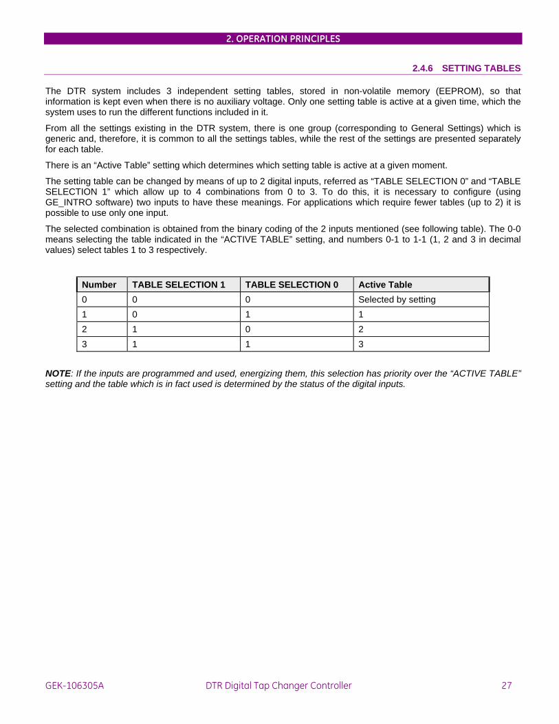
2.4.6 SETTING TABLES
The DTR system includes 3 independent setting tables, stored in non-volatile memory (EEPROM), so that information is kept even when there is no auxiliary voltage. Only one setting table is active at a given time, which the system uses to run the different functions included in it.
From all the settings existing in the DTR system, there is one group (corresponding to General Settings) which is generic and, therefore, it is common to all the settings tables, while the rest of the settings are presented separately for each table.
There is an “Active Table” setting which determines which setting table is active at a given moment.
The setting table can be changed by means of up to 2 digital inputs, referred as “TABLE SELECTION 0” and “TABLE SELECTION 1” which allow up to 4 combinations from 0 to 3. To do this, it is necessary to configure (using GE_INTRO software) two inputs to have these meanings. For applications which require fewer tables (up to 2) it is possible to use only one input.
The selected combination is obtained from the binary coding of the 2 inputs mentioned (see following table). The 0-0 means selecting the table indicated in the “ACTIVE TABLE” setting, and numbers 0-1 to 1-1 (1, 2 and 3 in decimal values) select tables 1 to 3 respectively.
Number TABLE SELECTION 1 TABLE SELECTION 0 Active Table 0 0 0 Selected by setting 1 0 1 1 2 1 0 2 3 1 1 3
NOTE: If the inputs are programmed and used, energizing them, this selection has priority over the “ACTIVE TABLE” setting and the table which is in fact used is determined by the status of the digital inputs.

2. OPERATION PRINCIPLES
28 DTR Digital Tap Changer Controller GE—106305A
2.5 USER INTERFACE AND COMMUNICATIONS
2.5.1 LOCAL USER INTERFACE
The local man machine interface in the DTR system is developed through two keyboard/display sets, one for protection functions and the other for control functions.
Local Protection MMI The protection HMI incorporates keyboard with 20 keys and an alphanumeric LCD display with two rows of 16 characters each, that allows access to all the information available in the protection system, that is:
Display and change settings
Display of states and measurements
Perform actions (operations)
Access to the Configuration Menu and to the Single Key Menu (this menu shows the most important information of the device by pressing only one key)
Control Local MMI The control HMI incorporates functional keyboard with 6 keys and graphic LCD display. This graphic LCD shows four different screens that can be accessed sequentially.
- BAY MIMIC
- This screen shows the mimic of the bay, that is, a diagram of the bay related to the DTR module, showing the status of the transformer OLTC, tap number, measured voltage, setpoint and other information. This screen can be configured with the GE_Intro configuration software. The following picture shows an example of this screen:
In this screen, the different elements can be selected (by means of the arrow keys) and the user can perform operations related to those elements. When the user selects an element that can be operated, the display shows the available options that can be selected with the F1.F4 keys.

2. OPERATION PRINCIPLES
GEK-106305A DTR Digital Tap Changer Controller 29
- ALARMS SCREEN
This screen shows the alarms generated in the system with the following format:
Alarm label
Time when the alarm was generated with 1 ms resolution
Date of the alarm
- MEASUREMENTS SCREEN
This screen shows the real time measurements associated with the DTR system.

2. OPERATION PRINCIPLES
30 DTR Digital Tap Changer Controller GE—106305A
- DIGITAL INPUTS AND OUTPUTS STATUS SCREEN
This screen shows the status of all the inputs and outputs. A dark background means that the input or output is activated. The following figure shows this screen:

2. OPERATION PRINCIPLES
GEK-106305A DTR Digital Tap Changer Controller 31
2.5.2 REMOTE COMMUNICATIONS. SOFTWARE
The relay has 2 serial gates and three connectors. Gate 1 can be reached from the front of the relay in connector 1 (PORT 1 connector) or from the rear (PORT 2 connector). The second gate can be reached from connector 3 (PORT 3 connector) which is located on the rear.
There are different models each with a different physical connection for the PORT 3 connector (RS3232 or fiber-optic). In the “RS232” models the three connectors are RS232. In the “RS232 and fiber-optic” models the PORT1 and PORT2 connectors are RS232 while the PORT3 connector is replaced by a fiber-optic connector.
The PORT 1 connector has priority over the PORT 2 connector and is selected when the DCD (Data Carrier Detect) signal is activated. Fig8 shows how to make the connections to a personal computer.
The communications protocol is the same as that used for the rest of the GE digital protection systems and requires the use of the GE_LOCAL software. The protocol is reliable and allows communication with different protection systems. It guarantees very efficient data transfer (especially for large files) along with error detection and automatic communication recovery.
The status of the local/remote communication is indicated on the front of the unit by LED indicator 16 (in default configuration). Local communication refers to communication via the keyboard/display (local display showing any information except for the initial DTR GENERAL ELECTRIC), or via communication gate 1 (PORT 1), and remote communication refers to connection via gate 1 (PORT 2) or gate 2 (PORT 3).
Local and remote communications can exit at the same time, although there is only one possibility for changing settings and carrying out operations, since this can only be done with the communication which has priority (local communication) while the other is limited only to accessing information. When the local communication is interrupted, either by the disconnection of PORT 1 connector or because the HMI is on the initial screen (a situation which can be caused intentionally, or automatically if no key has been pressed for 15 minutes), the remote communication recovers the ability to modify and carry out operations.
The GE_NESIS software include five different programs, each one with a different function:
GE-LOCAL. Level 1 communication software.
GE-INTRO. Level 1 configuration software.
GE-POWER. Level 2 communication software.
GE-CONF. Level 2 configuration software.
The GE_Local and GE_Intro programs constitute the basic communication and configuration software for DTR systems, allowing the communication with one device at one time, either for level 1 devices integrated in a system or for non integrated devices (operating as individual relays).

2. OPERATION PRINCIPLES
32 DTR Digital Tap Changer Controller GE—106305A
The functions that can be performed with each program are the following:
GE-LOCAL:
Display of Level 1 units status
Display and change of settings
Display of metering data
Perform predefined operations
Reading, display and reset of counters
Display of alarms
Upload and display events
Upload oscillography records
Time synchronization
INCREASE
DECREASE
STOP
AUTOMATICMANUAL
REMOTELOCAL
SetpointVsecOper.
110,00 V109,25 V 30,00 s
TAP 19

2. OPERATION PRINCIPLES
GEK-106305A DTR Digital Tap Changer Controller 33
GE-INTRO:
Configuration of protection inputs and outputs
Configuration of control inputs and outputs
Configuration of alarms
Definition of operations and interlocking conditions
Definition and configuration of switching elements
Configuration of targets LED
Configuration of the screens shown on the graphic LCD.
GE-INTRO Screen
2. OPERATION PRINCIPLES
34 DTR Digital Tap Changer Controller GE—106305A
GE-POWER:
Display of the single line diagrams of the substation
Zoomed display of the single line diagrams of the bay
Access to information as:
Status
Measurements
Alarms
Events
Oscillography
for each bay and for the complete substation
Perform operations
Display and remote change of the setting of each bay
GE-CONF:
Configuration of users, access levels and security passwords
Configuration of bays (name, type, etc)
Configuration of states, measurements, events, etc., that each Level 1 unit must send to Level 2.
Configuration of databases, macro-operations and interlocks involving different bays.
Generation of databases for the substation.

3. SETTINGS
GEK-106305A DTR Digital Tap Changer Controller 35
3. SETTINGS
3.1 SETTINGS This section describes the settings incorporated in the DTR system, and the procedure for changing them. First a complete list of the DTR settings is shown, together with their limits, units and corresponding steps (the column marked DEFAULT indicates that this is the setting on the relay when it leaves the factory). This is followed by individual comments for those settings that require more detailed explanation.
It is possible to see the settings or to modify them manually, using the keyboard and display, or by means of a computer connected to any of the serial ports. To modify the settings by computer follow these instructions:
• Make sure that the available connection cable coincides with the diagram in figures 4 and 5, depending on if the serial port of your computer is DB9 or DB25.
• Connect the cable between the relay (or modem) and the serial port of your computer.
• Run the GE_LOCAL software. For more details on the installation and use of the software see the GE_LOCAL instruction book.
• Make sure that the program configuration communication parameters coincide with those of the DTR unit. More specifically, these parameters for the communication of the local HMI are as follows:
- COMMUNICATION BAUDRATE (for the relay depending on which port is being used: local or remote)
- STOP BITS (for the relay depending on which port is being used: local or remote)
To modify or view the unit’s configuration parameters go to the configuration menu, corresponding to section 8 “KEYBOARD AND DISPLAY”
When connecting to the unit, check that the relay number and password coincide with those which appear on the unit’s configuration menu.
The DTR system has 3 settings tables stored in non-volatile memory (EEPROM), and these can be selected by setting or configurable inputs. There is also a set of independent settings, common to all the tables. The following category contain the settings common to the 3 tables:
GENERAL SETTINGS
The remaining categories, shown below, contain the settings which can be selected independently for each of the 3 tables:
REGULATION SETTINGS
BLOCK SETTINGS
TIMERS
VOLTAGE SETPOINT
It should be noted that in order to simplify settings the unit and for safety reasons, all settings related to the configuration of the unit (configurable inputs and outputs, alarms, events, etc.) have been removed from the keyboard / display and communication software. To carry out these configurations the GE_INTRO configuration software must be run (refer to GEK-105569 for further information).

3. SETTINGS
36 DTR Digital Tap Changer Controller GE—106305A
The following table shows the DTR settings:
RELAY TEXT GROUP LIMITS DEFAULT GENERAL SETTINGS 1 0 RELAY STATUS 1 1 (0/1):Out / In service 0: Out of service IDENTIFICATION 1 2 20 ASCII characters No Id. FREQUENCY 1 3 (0/1):50/60 Hz 50 Hz VT RATIO 1 4 1-4000 1 CT RATIO 1 5 1-4000 1 ACTIVE TABLE 1 6 1-3 1 ALGORITHM 1 7 (1/2):Voltage / Calculus 1: Voltage RATED VOLTAGE 1 8 50-210 Vol. 110 Vol. RATED CURRENT 1 9 1-5 Amp 5 Amp OPERATIONS NUMBER 1 10 0-65535:0->Out of service 0:Out of service SUCCESSIVE OP. Nº 1 11 0-60:0->Out of service 0: Out of service TIME WINDOW 1 12 1-60 min 1 min MINIMUM TAP 1 13 1-40 1 MAXIMUM TAP 1 14 1-40 21 VOLTAGE TYPE 1 15 Phase-to-ground/phase-to-phase Phase-to-ground DIR/INV MODE 1 16 DIR/INV DIR FACTOR CAL. 1 17 950/1050 1000 REGULATION SETTINGS X1 0 INSENSITIVITY X1 1 0,5-5 % of Vn 1 TIME FACTOR X1 2 1-100 3 ACCELERATED TAP-DOWN
X1 3 90-150 % of Vn 120
CALCULATION X1 4 0-10 % of Vn 1 MAXIMUM TAP-UP X1 5 3-15 % of Vn 15 BLOCK SETTINGS X2 0 OVERVOLTAGE X2 1 90-150 % of Vn 120 UNDERVOLTAGE X2 2 0-120 % of Vn 50 OVERCURRENT X2 3 0-200 % of In 150 TIMERS X3 0 OPERATION PULSE X3 1 0,02-60,00 sec 5 sec SUCCESS TIME X3 2 0,02-60,00 sec 10 sec SETPOINT X4 0 SETPOINT X4 1 80-120 % de Vn 100
3. SETTINGS
GEK-106305A DTR Digital Tap Changer Controller 37
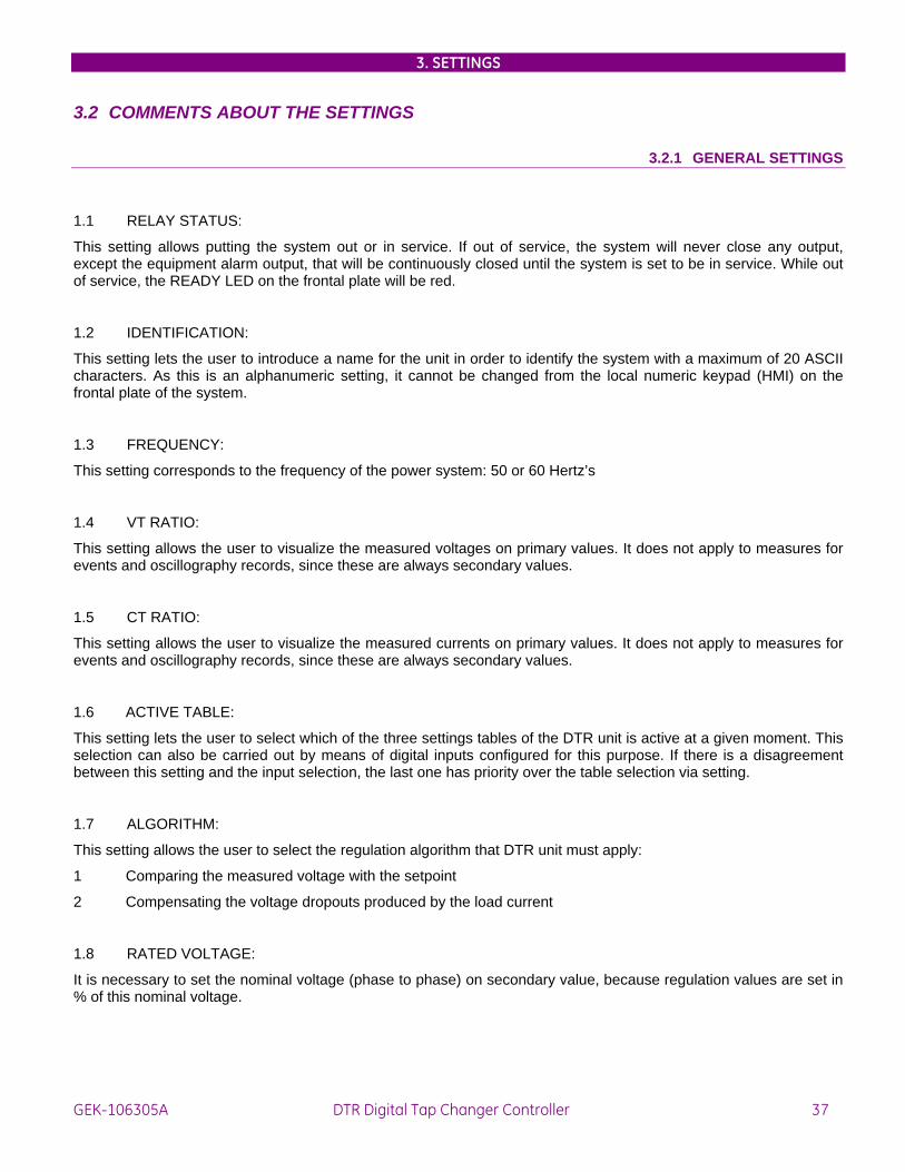
3.2 COMMENTS ABOUT THE SETTINGS
3.2.1 GENERAL SETTINGS
1.1 RELAY STATUS:
This setting allows putting the system out or in service. If out of service, the system will never close any output, except the equipment alarm output, that will be continuously closed until the system is set to be in service. While out of service, the READY LED on the frontal plate will be red.
1.2 IDENTIFICATION:
This setting lets the user to introduce a name for the unit in order to identify the system with a maximum of 20 ASCII characters. As this is an alphanumeric setting, it cannot be changed from the local numeric keypad (HMI) on the frontal plate of the system.
1.3 FREQUENCY:
This setting corresponds to the frequency of the power system: 50 or 60 Hertz’s
1.4 VT RATIO:
This setting allows the user to visualize the measured voltages on primary values. It does not apply to measures for events and oscillography records, since these are always secondary values.
1.5 CT RATIO:
This setting allows the user to visualize the measured currents on primary values. It does not apply to measures for events and oscillography records, since these are always secondary values.
1.6 ACTIVE TABLE:
This setting lets the user to select which of the three settings tables of the DTR unit is active at a given moment. This selection can also be carried out by means of digital inputs configured for this purpose. If there is a disagreement between this setting and the input selection, the last one has priority over the table selection via setting.
1.7 ALGORITHM:
This setting allows the user to select the regulation algorithm that DTR unit must apply:
1 Comparing the measured voltage with the setpoint
2 Compensating the voltage dropouts produced by the load current
1.8 RATED VOLTAGE:
It is necessary to set the nominal voltage (phase to phase) on secondary value, because regulation values are set in % of this nominal voltage.

3. SETTINGS
38 DTR Digital Tap Changer Controller GE—106305A
1.9 RATED CURRENT:
The DTR system can work with current transformers with nominal current 1Amp or 5Amp, user only has to wire to terminals B3-B4 for 1Amp or terminals A7-A8 for 5Amp. It is necessary to set the nominal current in these settings in order to let DTR know which terminals must use.
1.10 NO. OF OPERATIONS
This setting allows the user to set the maximum number of allowed operations on the OLTC before blocking the regulation automatism in its automatic mode. If the user set this setting to 0, this function is Out of Service, the operations counter is never increased and there is no blocking on the regulation automatism.
1.11 NO. OF SUCCESSIVE OP.
1.12 TIME WINDOW:
These settings allow setting the number of allowed operations in a determined period of time. When it is set to 0, this function is Out of Service.
1.13 MAXIMUM TAP:
This setting tells to DTR system the maximum tap number available in the OLTC, so when DTR reaches this tap, it never will try to raise the tap even if the voltage level requires it.
1.14 MINIMUM TAP:
This setting tells to DTR system the minimum tap number available in the OLTC, so when DTR reaches this tap, it never will try to lower the tap even if it is required by the voltage level.
1.15 VOLTAGE TYPE
To calculate cos Φ and the power values we need to select using this setting the VT voltage, either phase-to-ground or phase-to-phase.
1.16 DIRECT/INVERSE MODE
When in DIRECT MODE, the unit assumes that to increase the line voltage level it is necessary to raise the regulator tap, and to decrease the line voltage, we will need to lower the tap.
When in INVERSE MODE, the unit assumes that to increase the line voltage level it is necessary to lower the regulator tap, and to decrease the line voltage, we will to raise the tap.
1.17 CALIBRATION FACTOR
In order to approximate the relay measure to the real line measure in operating conditions, this setting is used to center the relay measure if any deviation is detected. The setting modifies the measured voltage value up to a ± 5% in steps of 0.1%

3. SETTINGS
GEK-106305A DTR Digital Tap Changer Controller 39
3.2.2 X1.REGULATION SETTINGS
X1.1 INSENSITIVITY:
This setting is the voltage variation that DTR allows before the system generates an order to change the tap in the OLTC. It is set in % of the nominal voltage.
X1.2 TIME FACTOR:
This setting is the factor that multiplies the base time to get the operation time (see section 2.1.1)
X1.3 ACCELERATED TAP-DOWN:
This setting is a voltage threshold. Below this limit the operation time to lower the tap is 0 seconds. It is set in % of the nominal voltage.
X1.4 CALCULATION
X1.5 MAXIMUM TAP-UP:
(see section 2.1.1, algorithm-2). It is set in % of the nominal voltage.
X2. BLOCK SETTINGS
X2.1 OVERVOLTAGE
If the measured voltage is greater than this value, the operation of a DTR system in automatic mode is blocked. It must be introduced in % of the nominal voltage.
X2.2 UNDERVOLTAGE
If the measured voltage is lower than this value, the operation of a DTR system in automatic mode is blocked. It must be introduced in % of the nominal voltage.
X2.3 OVERCURRENT
If the measured current is greater than this value, the operation of a DTR system in automatic mode is blocked. It must be introduced in % of the nominal current.
3.2.4 X3. TIMERS
X3.1 OPERATION PULSE:
This is the time that DTR system maintains the output that acts over the OLTC closed.
X3.2 SUCCESS TIME:
This is the time that DTR system must wait before deciding if a TAP-UP or TAP-DOWN operation has not been successfully completed

3. SETTINGS
40 DTR Digital Tap Changer Controller GE—106305A
3.2.5 X4. VOLTAGE SETPOINT
X4.1 SETPOINT:
This setting is the required voltage level. This voltage level must be kept constant. It must be introduced in % of the rated voltage in accuracy steps of 0.1%.

4. PROGRAMMING THE UNIT
GEK-106305A DTR Digital Tap Changer Controller 41
4. PROGRAMMING THE UNIT
DTR units incorporate inputs, outputs, and a graphical display, all of them programmable by the user. The programming of all these elements is used by means of GE-INTRO software (instruction manual GEK-105594).
4.1 INPUT CONFIGURATION Each programmable input can be assigned to the following values:
CONFIGURABLE INPUTS Table *1 Table *2 External trigger Interlocking-1 Interlocking-2 Regulator alarm BCD_1 BCD_2 BCD_3 BCD_4 BCD_5 BCD_6 Tap-up Tap-down Automatic Manual Remote Local Stopped Remote Trip Tap 1 Tap 2 Tap 3 Tap 4 Tap 5 Tap 6 Tap 7 Tap 8 Tap 9 Tap 10 Tap 11

4. PROGRAMMING THE UNIT
42 DTR Digital Tap Changer Controller GE—106305A
CONFIGURABLE INPUTS Tap 12 Tap 13 Tap 14 Tap 15 Tap 16 Tap 17 Tap 18 Tap 19 Tap 20 Tap 21 Tap 22 Tap 23 Tap 24 Tap 25 Tap 26 Tap 27 Tap 28 Tap 29 Tap 30
Additionally to these possibilities, we can use programmable inputs for creating logic schemes using logic AND/OR/NOT gates with the inputs, and assigning them to outputs. For creating these schemes, we must program inputs as “Void input”.
The following lines detail the operation of each input:
• Selection table 1 : This input is activated by level, and it’s used for switching the active settings table. Please refer to section 2.5 for further details.
• Selection table 2 : As in the previous case.
• Interlocking 1: Used for blocking the operation of the regulation automatism (in automatic mode).
• Interlocking 2: Used for blocking the operation of the regulation automatism (in automatic mode).
• Regulator Alarm: Signals the activation of the Alarm input in the commuter
• BCD_1 to BCD_6: Used for informing the unit, using BCD (Binary Coded Decimal) coding, of the tap where the OLTC is located.
• Tap-up: This input commands a tap increase.
• Tap-down: This input commands a tap decrease.
• Automatic: Command for switching to the Automatic operation mode.
• Manual: Command for switching to the Manual operation mode.
• Remote: Command for switching to the Remote operation mode.
• Local: Command for switching to the Local operation mode.
• Stopped: Command for stopping the regulation automatism.

4. PROGRAMMING THE UNIT
GEK-106305A DTR Digital Tap Changer Controller 43
• Remote Trip: Operation over the element associated to that input (either an output contact or an operation) independently from the relay operation mode.
• Tap 1 to Tap 30: Used for informing the unit of the tap where the OLTC is located, using a consistent codification in a contact per tap.

4. PROGRAMMING THE UNIT
44 DTR Digital Tap Changer Controller GE—106305A
4.2 OUTPUT CONFIGURATION
DTR units incorporate 22 programmable outputs. Any of the internal protection statuses shown in section 21.2.3 can be assigned to a programmable output. We can also associate a programmable output to the activation or deactivation of an internal status. In this same way, we can perform AND/OR/NOT logic schemes with the outputs.
4.3 GRAPHIC DISPLAY CONFIGURATION DTR units incorporate on the right side of the faceplate, a graphical display of 112x62 mm. This display shows a mimic of the bay associated to the DTR unit.
The stand-by screen is as follows:
The keypad used for accessing the different screens and operating on the existing elements in each screen is located on both sides of the graphic display, as follows:
On the left side, there are two keys with up and down arrows. These arrows allow to make a selection among the different elements displayed, as shown beside the arrows.
On the right side, there are several function keys, F1, F2, F3, F4. Depending on the displayed screen, the display will show beside the function key, a message showing which operation we can perform. (E.g.: in the above display, we can see an ALARMS legend close to F1 key, this means that by pressing that key, we will move to the Alarms screen).
After 15 minutes without any of the keys being pressed, the display will turn off automatically in order to avoid unnecessary consumption. It will turn on again by pressing any of the keys.

4. PROGRAMMING THE UNIT
GEK-106305A DTR Digital Tap Changer Controller 45
4.4 MAIN SCREEN
The following diagram shows the main screen. It represents the bay scheme or mimic.
When in stand-by, none of the elements in the display is selected. By pressing the keys on the left side, we can move through the elements on which we can operate (tap-up, tap-down, stop, automatic, manual). When selected, the element will be shadowed, and the F4 key will show which operation can be commanded.
OPERATE F4 If we press the operation key, the relay will ask for confirmation or cancellation of the operation, as follows:
CANCEL F1 CONFIRM F2
If the operation is not performed, for example, because there is a programmed block that disables it, the display will read:
OPERATION FAILURE
Besides, in the main screen, instead of showing “CANCEL”, it will show “MENU SELEC”, to return to the initial menu of the operation selection.

4. PROGRAMMING THE UNIT
46 DTR Digital Tap Changer Controller GE—106305A
If the operation is performed correctly, the relay will show the following message:
OPERATION PERFORMED
4.5 ALARMS SCREEN If we move from the main screen to the alarms screen, by pressing F1, as shown on the main screen graphic, the relay will show a new screen, as the one below:
This screen shows a list of alarms that have been generated in the substation. The maximum number of alarms that can be displayed is 12. Alarms are displayed as follows:
Alarm label, that is, associated text defined in GE-INTRO software Time and date when the alarm was generated
When an alarm is produced, the screen shows the previous information with a dark shadow and blinking. The blink and the shadow indicate that the alarm has not been acknowledged. In order to “acknowledge” the alarm, we must press F2, as indicated in the help text shown at the bottom of the screen. Once the alarm has been acknowledged, it stops blinking and the shadow disappears, but the alarm text remains on the screen until the reason that produced it disappears.
At the bottom of the screen we can see the text “ACTIVE ALARM, NOT ACKNOWLEDGED”, “ACTIVE ALARM”, etc. showing the status for each alarm.
The representation for the different possible statuses of an alarm are as follows:
Active alarm, not acknowledged: Blinking, with a dark shadow, and marked with an asterisk
Active alarm, acknowledged: Without blinking, marked with an asterisk.
Inactive alarm, not acknowledged: Without blinking, with a dark shadow, without asterisk.
Inactive alarm, acknowledged: Disappears from the screen.

4. PROGRAMMING THE UNIT
GEK-106305A DTR Digital Tap Changer Controller 47
The help text shown at the bottom displays the possible actions that can be taken in that screen:
Arrows are used from moving from one alarm to another
By pressing F1, we move to the MEASURES screen
By pressing F2, we acknowledge the selected alarm (when we are placed on an alarm, its colour is shown in negative).
By pressing F3, we automatically acknowledge all the alarms appearing on the alarms screen.
4.7 MEASURES SCREEN
If we move from the alarms screen to the measures screen, the display will look as below:
The displayed values are values on the primary side.
4.8 INPUTS/OUTPUTS SCREEN
From the measures screen, we can move to the inputs/outputs screen by pressing the F1 key. The displayed screen will look as follows:
Those inputs/outputs active at a given moment, will be displayed with a dark shadow.

4. PROGRAMMING THE UNIT
48 DTR Digital Tap Changer Controller GE—106305A

5. TECHNICAL CHARACTERISTICS
GEK-106305A DTR Digital Tap Changer Controller 49
5. TECHNICAL CHARACTERISTICS
5.1 MODEL LIST
POSITION DTR 1 - 0 - - 0 0 0 - - - A DESCRIPTION
Communications. Rear port:
0 P2 : RS232 5 1 P2 : Plastic FO 2 P2 : Glass FO 3 P2 : RS-485
Protocol (per port). 7 0 P1, P2 → MLINK 2 P1, MLINK; P2 MODBUS
HMI Language 8 M Spanish D English
Auxiliary Voltage 12 G Vaux = 48 / 125Vdc. H Vaux = 110/250Vdc.
13-14 0 0 Standard model. X X Special models
Note:
- All units have a front RS232 communications port
- Special model 01 incorporates, in addition to the BCD coded input tap changer, the possibility to use one contact per tap. There is no additional setting; instead, when programming (using GE-INTRO) inputs as Tap1, Tap2, etc. the unit assumes that the tap status will be made following the code “one contact per tap”. This codification has priority over the BCD. In the event that inputs were assigned by mistake, both for BCD and for one contact per tap codifications, the last one would be used.

5. TECHNICAL CHARACTERISTICS
50 DTR Digital Tap Changer Controller GE—106305A
5.2 TECHNICAL CHARACTERISTICS
MECHANICAL
• Metallic package in 19’’ rack case, 4 units high.
• Protection degree IP51 (according to IEC 529).
• Local HMI with LCD screen of 2 lines x 16 characters, and 20-key keypad
• Rear connection through terminal boards of 12 terminals each
• Dimensions: 437 x 200 x 176 mm
• Weight: Net 12 kg. Packaged: 13 kg.
FREQUENCY METERING CHARACTERISTICS
• Accuracy: ±200 PPM at 20ºC
• Repetitivity (*): ±50 PPM
• Error by temperature: ±35 PPM from -20ºC to +55ºC
• Stability: ±5 PPM according to MIL-C3098F
• hysteresis: 0.04 Hz
(*) when a stable frequency generator is used, for example Multiamp EPOCH20 in fixed frequency position (either 50 or 60 Hz).
ELECTRICAL CHARACTERISTICS
• Frequency: 50 or 60 Hz
• Rated Voltage: 90 to 220 Vac
• Auxiliary Voltage: 48/125 Vdc or 100/250 Vdc ( depending on model ) ± 20%
• Input auxiliary voltage: 48, 125,220 Vdc ( depending on model)
• Thermal capacity:
Voltage circuits - Continuous: 2 x Un
- During 1 min: 3.5 x Un
Current circuits - Continuous: 4 x In
- During 3 sec: 50 x In
- During 1 sec: 100 x In
• Temperature:
- Operation: -20°C to +55°C
- Storage: -40°C to +70°C

5. TECHNICAL CHARACTERISTICS
GEK-106305A DTR Digital Tap Changer Controller 51
• Humidity : Up to 95% without condensing
• Tripping contacts:
- Rated voltage, maximum opening voltage :
250/440 VAC
- Rated current / closing current. 16/25A
- Operation power
- Mechanical life
4000 VA
3 x 10E6 ops
• Consumption:
- Voltage circuits: 0.2 VA for Un = 90 V
- Continuously: 12 W
- Per active input: 8 mA (1 W Vaux = 125 Vdc)
OUTPUT RELAYS
Configuration 6 commuted electromechanical
Contact material: Silver alloy for inductive loads
Maximum ranges for 100000 operations:
VOLTAGE CLOSING (continuous)
CLOSING 0.2 sec
BREAKING MAXIMUM LOAD
DC resistive 24 Vdc 16 A 48 A 16 A 384W 48 Vdc 16 A 48 A 2.6 A 125W 125 Vdc 16 A 48 A 0.6 A 75 W 250 Vdc 16 A 48 A 0.5 A 125 W DC Inductive 24 Vdc 16 A 48 A 8 A 192 W 48 Vdc 16 A 48 A 1.3 A 62 W 125 Vdc 16 A 48 A 0.3 A 37.5 W 250 Vdc (L/R=40ms)
16 A 48 A 0.25 A 62.5 W
AC Resistive 120 Vac 16 A 48 A 16 A 1920 VA 250 Vac 16 A 48 A 16 A 4000 VA AC Inductive FP = 0.4
120 Vac 16 A 48 A 11.2 A 1344 VA 250 Vac 16 A 48 A 11.2 A 2800 VA

5. TECHNICAL CHARACTERISTICS
52 DTR Digital Tap Changer Controller GE—106305A
COMMUNICATIONS - Mode: Half duplex.
- Baudrate : 1200 to 19200 bauds
- Physical media:
- RS232 ( ports 1,2 )
- Plastic fiber optic ( port 2 Optional )
Type of connector : HFBR-4516
Typical emitted power : -8dBm
Receiver’s sensitivity : -39dBm
Wave length: 660 nm
- Glass fiber optic ( port 2 Optional )
Type of connector : STA
Typical emitted power: -17.5 dBm
Receiver’s sensitivity: -24.5 dBm
Wave length : 820 nm.
- RS485 ( port 2 optional)

5. TECHNICAL CHARACTERISTICS
GEK-106305A DTR Digital Tap Changer Controller 53
STANDARDS DTR units comply with the following standards, including GE standard for isolation and electrical compatibility, and the standards required by community directive 89/336 for CE marking, according to harmonized European standards. They comply also with the low voltage European directive, and the environmental and operational requirements established under standards ANSI C37.90, IEC 255-5, IEC 255-6 and IEC 68.
Test Standard Class • Isolation and voltage impulse IEC 255-5 600V, 2kV 50/60 Hz 1 minute
• Shock wave IEC 255-5 5 kV, 0.5 J
• Interferences 1 MHz IEC 255-22-1 III
• Electrostatic discharge IEC 255-22-2 EN 61000-4-2
IV 8 kV
• Immunity to radiated interferences IEC 255-22-3 III
• Radiated electromagnetic fields, modulated in amplitude
ENV 50140 10 V/m
• Radiated electromagnetic fields, modulated in amplitude. Common mode
ENV 50141 10 V/m
• Radiated electromagnetic fields, modulated in frequency
ENV 50204 10 V/m
• Fast transients IEC 255-22-4 EN 61000-4-4
IV
• Magnetic fields at industrial frequency EN 61000-4-8 30 Av/m
• RF Emission EN 55011 B

5. TECHNICAL CHARACTERISTICS
54 DTR Digital Tap Changer Controller GE—106305A

6. HARDWARE DESCRIPTION
GEK-106305A DTR Digital Tap Changer Controller 55
6. HARDWARE DESCRIPTION
WARNING
The DTR system incorporates electronic components that might be affected by electrostatic discharge currents flowing through certain components terminals. The main source of electrostatic discharges is human body, specially under low humidity conditions, with carpet floors or isolating shoes. If such conditions are present special care should be taken while manipulating DDS’s modules and boards. Operators, before even touching any component, must make sure that their bodies are not charged by either touching a grounded surface or by using an antistatic grounded wrist bracelet.
6.1 MECHANICAL CONSTRUCTION
6.1.1 BOX CONSTRUCTION
The DTR modules are assembly in box of an standard 19’’ rack four units high, manufactured in stainless steel and painted with gray epoxy resin. It is composed of a backbone structure, that includes the strips where all the modules and boards are connected, plus a rear plate with all the female connectors.
All the boxes have a surge ground connection terminal, essential not only in terms of safety but also on behavior against electromagnetic interference.
All the modules are of draw-out type, enabling easy maintenance and repair of the equipment.
The DTR also incorporates a plastic antitampering front cover. This cover keeps the relay sealed and provides a high protection against dust and water (IP51 index according to IEC 529). The use of a push-button allows access to the main functions without the need of removing the cover.
The front and rear views of a typical DTR equipment are shown on figures 6 and 7.
6.1.2 ELECTRICAL CONNECTIONS.
All the DTR electrical connections (voltage inputs and digital I/Os) are done through drawout terminal boards of 12 terminal blocks each located at the rear of the device.
Additionally to those terminal blocks, the DMS includes two communication ports. One front DB-9 port for local connection and another located on the rear nameplate, used for remote connection to the PC.
This second port may be used for point-to-point connection with a central computer in the substation by means of a multiplexer.
This second communication port may be, depending on the selected option, a RS232 with a DB-9 connector, a fiber optics (glass or plastic) connector or finally an RS-485.
In the rear plate are also included the terminal blocks for the time synchronization through a demodulated IRIG-B input.

6. HARDWARE DESCRIPTION
56 DTR Digital Tap Changer Controller GE—106305A
6.1.3 INTERNAL CONSTRUCTION.
The internal architecture of DTR modules, includes the following 4 units high drawout modules:
- Magnetic Module (CT and VT analog inputs)
- Protection CPU board
- Communications CPU board.
- 2 mix modules: power supply + digital inputs/outputs (redundant backup power supply)
- 2 mix modules for digital inputs and outputs.
- 1 digital inputs module
Each of these modules has a DIN type front connector for the connection to the internal communication bus. Also, in the case of having connections to the outside (Inputs, Outputs and power supply modules), the male part of the terminal block is incorporated. The female portion of the connector is located in the rear plate of the box. All these boards are inserted in the box perpendicularly to the rear plate.
Besides all these modules there are some other boards mounted in parallel to the front of the box. These boards are:
- Internal bus board. This is a PCB board that makes the connection between the digital inputs and the power supply through their front DIN connectors.
- Front display board. It is a PCB that includes the two LCD displays of the DTR units, the alphanumeric display for the protection management, and the programmable graphic display, as well as its associated electronics, including the controls of brightness and contrast of the displays. Additionally, the board includes the front communications connector, the switch for local/remote operation selection of the control position and the bicolor LED indicator of the equipment state.
The front module is mechanically and solidly connected to the keypad board, the electrical connection is done through a flexible flat cable of 12 pins.
The subgroup formed by these two front boards is connected to the rest of the relay through another flexible flat cable of 40 pins, connected itself to the front of the communications CPU.
- Front keypad board It is a printed board which is solidly joined to the front board of the display, as mentioned before, and supports the keypad for the protection operation (20 keys alpha-numeric and functional keypad that acts on the alpha-numeric display) The board also includes a transparent window for the display and for the control board in which the unit identification (model number and serial number) and its more relevant technical characteristics are included.
The group formed by both front boards is mechanically and electrically joined to the box by means of 4 screws placed at upper and lower part of the front. To get the access to the internal electronic modules of the relay the next steps must be followed (once the relay has been disconnected):
1. Remove the plastic cover.
2. Slack the fixed frontal screws till they are untied and only fixed by their fastening sleeve.
3. Let the front part fall softly till the flat cable, that is connected to the communications board, is accessible, and unfasten the extreme connected to this board.
4. Remove the frontal module.

6. HARDWARE DESCRIPTION
GEK-106305A DTR Digital Tap Changer Controller 57
5. Take out the internal bus board which fixes the different modules themselves.
If this process is followed, every relay module can be accessed in order to be taken out, maintained or replaced. In order to assembly the relay again, the procedure is the contrary, that is to say:
1. Make sure that every vertical drawout module has been correctly inserted.
2. Assembly the internal bus board which joins the different modules themselves by pressing from left to right every connector in order to be sure of their right insertion.
3. Connect the flat cable that connects the frontal module with the communications board.
4. Place the frontal module at its position and screw it on the box.
5. Cover again the relay with its protective cover.
6.1.4 IDENTIFICATION
The identification label of the model is placed at the right of the alpha-numeric keypad. This label includes the model number, serial number and the most important nominal values (including nominal voltage and current, and DC power supply nominal voltage).
Terminal blocks placed at the rear cover are identified by black color serigraphy on the cover (see figure 5.2.). Each of the terminals blocks are identified by a letter placed at the upper border of the cover close to the connector. This connector identification is assigned to the different connectors, beginning by A which corresponds to the connector placed on the right extreme (looking at the relay from the back).
In the terminal blocks, each of the 12 terminals of each block is identified from the top to the bottom by a number between 1 and 12 that is serigraphied on the cover close to each connector at the input side of the connection cables. The connector terminals for synchronization are identified by “IRIG-B” serigraphy and the terminals polarity is indicated by “+” and “-”.
For relays with fiber optics communications (plastic or crystal), transmission and reception connectors terminals are identified by TX and RX serigraphy respectively.
6.1.5 MAGNETIC MODULE.
Magnetic module takes voltage signals of the substation conventional transformers, and with these signals performs the following:
- It gives galvanic isolation to external signals by means of relay internal transformers.
- It makes suitable the external signals to the adequate voltage levels for the internal circuitry.
Anti-noise filters are another element of the module. As the magnetic module is connected to external switchgear signals, it can be affected by electromagnetic disturbance. In order to avoid their effect, anti-noise filters have been included in the transformers’ primary (capacitors connected to chassis), as well as in the secondary (ferrites), so as to prevent disturbance from entering the equipment. These protection elements act as well as a barrier, preventing possible disturbances generated in the protection equipment to come out of this and affect the external equipment.
The last element included in the magnetic module consists of load resistors that convert the current signals in voltages, in the current signals case, and of resistive attenuators in the voltage signals case.

6. HARDWARE DESCRIPTION
58 DTR Digital Tap Changer Controller GE—106305A
6.1.6 PROTECTION CPU PROCESSING BOARD
This module is the main part of the equipment with reference to protection functions. The main functions are:
- Sampling of analog signals coming from magnetic module.
- Protection algorithm evaluation.
- Protection logic and auxiliary functions.
- Monitoring functions, events register, oscillography register, etc.
- Equipment self-check.
- Protection data communication to the communications CPU.
CPU module nucleus is a 16 bits microprocessor together with its auxiliary associated circuitry.
6.1.7 CPU COMMUNICATIONS BOARD.
Communications CPU module nucleus is very similar to the protection CPU module, and it also consists of a 16 bits microprocessor together with the auxiliary electronic.
The main function of the communications CPU module is to maintain and control the communications in the following channels:
- Internal communication with the protection and control CPU modules.
- Local mode communication with a PC by the front communications port.
- Remote mode communication by rear communication port.
- Man-machine interface by means of keypads and displays (alphanumerical and graphical).
6.1.8 DIGITAL INPUTS BOARD.
The design of the DTR has been done for assuring the maximum capacity of inputs by board, maintaining at the same time the maximum reliability against electromagnetic disturbance.
Each of the board inputs has a resistive attenuate which adequates the external voltage battery levels (48 V, 125 V, ...) to the needs of the optocoupler that gives galvanic isolation to each input. As the majority of these inputs come from elements that are connected to the substation equipment, together with the resistive attenuate one passive filter is provided in order to get better behavior against electromagnetic perturbations.
Input modules (as well as the output ones), provide one selectable of 4 bits address, which allows to include several modules of each kind in the same DTR unit.

6. HARDWARE DESCRIPTION
GEK-106305A DTR Digital Tap Changer Controller 59
6.1.9 DIGITAL OUTPUTS BOARD
Each of the DTR output boards includes 12 heavy duty relays, 16 Amperes nominal continuous capacity and 4000 VA breaking capacity or signaling, of continuos nominal capacity of 8 Amp. Each of these relays has an only contact (NO). The contact of each relay can be set separately as normally close or normally open by jumpers (fixed by welding) placed on the board.
In every configuration the contacts are non potential contacts, without common elements and all of them have varistors between their terminals in order to protect them against overvoltages generated by the coils they are connected to. This provides a high immunity against electrical interferences.
6.1.10 POWER SUPPLY
The Power Supply module includes the following functions:
• Generation of the necessary voltages for the operation of the DMS modules circuitry, in this case 8V (subsequently regular to 5 V) for the logic, and 24 V for the tripping activation.
• Four relays, with the same characteristics as the ones included in the outputs board (2 relays for tripping functions and 2 relays for reclosing).
• An auxiliary relay for equipment alarm.
As regards the power supply board we should emphasize that:
- One passive filter is included in the power supply input in order to avoid any possible electromagnetic disturbances. A current limiter is also included in order to protect the power supply against unintentional groundings.
- The tripping relays are stronger (in capacity and in control operations life) than the normal ones used for similar protection equipment. Besides this, as the output contacts type can be configured, a high versatility is provided.
- The output circuits for feeding other boards are conditioned so that they can have several boards connected, being possible to switch the service from one board to another one in case of failure, increasing the reliability of the equipment.

6. HARDWARE DESCRIPTION
60 DTR Digital Tap Changer Controller GE—106305A
6.2 RECEPTION, HANDLING & STORAGE DTR modules are supplied to the customer in a special package, which adequately protects it during transportation, as long as this is performed in normal conditions. Immediately after receiving the equipment, the customer should check whether it shows any signs of transportation damage. If it is apparent that the equipment has been damaged by inappropriate handling, it must be immediately advised in writing to the carrier, and the damage must be reported to the manufacturer
For unpacking the relay, normal care should be taken in order not to lose the screws, documents and other auxiliary elements also supplied in the box.
If it is not intended to install the relay immediately, it is recommended to store it in its original package, and keep it in a dry, dust free and metal particles free place.
6.3 INSTALLATION DTR units must be mounted in vertical surface which allows access to the front and rear sides of the equipment. It is not necessary to have access to the lateral surfaces of the equipment mounted. Dimensions and panel drilling for boxes of a 19’’ rack 4 units high in shown in Figures 2 and 4.
7. ACCEPTANCE TESTS
In this section we will explain the different tests that allow verification of the complete functionality of a DTR protection equipment. For a given DTR equipment, only those tests corresponding to the functions included in it should be carried out, according to the table of application variables in the models selection guide.
7.1 VISUAL INSPECTION • Unpack the relay and make sure that there are no broken parts and that there are no signs that the relay has been
damaged during transportation
• Make sure that all the screws are well tightened and the terminals blocks are not damaged.
• Make sure that the device type indicated on the front plate matches with the order data.
7.2 INSULATION TEST
During the testing, the A12 terminal should be to connected to ground for security reasons. It must be verified that connection to ground exists in the terminal C12.
- Apply gradually 2500 volts between all the terminals of a group, connected among themselves, and the box, during a second.
7.3 POWER SUPPLY

7. ACCEPTANCE TESTS
GEK-106305A DTR Digital Tap Changer Controller 61
Apply nominal voltage (maximum and minimum) to the relay. For each of this voltages, check that the ALARM relay is open when it is powered and close when it is not powered.
Configure as trips all the configurable contacts. In this condition, check that the relay communicates correctly using a PC. Request the relay model using GE-LOCAL software.
The minimum and maximum voltage values to be applied to each model are as follows:
Model “G”
Maximum voltage: 150
Minimum voltage: 38.4
Model “H”
Maximum voltage: 300
Minimum voltage: 88

7. ACCEPTANCE TESTS
62 DTR Digital Tap Changer Controller GE—106305A
7.4 METERING Set the relay as follows:
“GENERAL SETTINGS”
VT = 1000
CT = 100
RATED CURRENT = 5 A.
FREQUENCY = 50 Hz or 60 Hz
VOLTAGE TYPE = COMPLEX
TABLE-1 1 2 3 4 5
V (A7-A8) (V) 10/0º 40/45º 80/90º 120/120º 160/150º
I (A1-A2) (A) 0 1,0 2,0 5,0 10,0
P (MW) 0 6,69 13,85 0 -138,5
Q (Mvar) 0 1,79 24,0 103,9 240
cosφ - 0,966 0,5 0 -0,5
1. Apply the voltage and current values from the table, at the specified network frequency
2. Current shall be applied through A1-A2.
3. Verify that the relay measures the frequency, voltage, and current with an accuracy of ±5%, and P, Q & cos φ with an accuracy of ±6%
7.5 VERIFICATION OF INPUTS 1. Apply to each input a voltage at 20% lower than the minimum admissible voltage for the input circuits.
2. Check that the relay acknowledges as active each and every input
3. Apply to each input a voltage at 20% higher than the maximum admissible voltage for the input circuits.
4. Check that the relay acknowledges as active each and every input

7. ACCEPTANCE TESTS
GEK-106305A DTR Digital Tap Changer Controller 63
7.6 COMMUNICATIONS Enter the hidden menu < 7169 > and set the following communication parameters:
Relay number 1
Local baudrate 19200
Remote baudrate 19200
Local stop bits 1
Remote stop bits 1
1. Request the relay model through the front port, previously checking that the PC communication parameters are the same as the relay’s.
2. Request the relay model through one of the rear ports, previously checking that the PC communication parameters are the same as the relay’s.
3. Request the relay model through the remaining rear port, previously checking that the PC communication parameters are the same as the relay’s.
7.7 DISPLAY, KEYPAD AND LEDS. 1. Press the following keys in the shown order, and check that the display shows the attached messages:
KEY MESSAGE SET SEE PROTECTION SETTINGS CLR DTR GENERAL ELECTRIC INF STATUS ENT MODEL UP arrow DATABASE DOWN arrow
MODEL
CLR STATUS CLR DTR GENERAL ELECTRIC ACT SET DATE/TIME CLR DTR GENERAL ELECTRIC 7169 BAUDRATE UP arrow NETWORK STOP BITS
2. Press 6 to 0 number keys, until you complete number 6543210.
3. Press the CLR key, and check that every time it is pressed, the last digit of the number disappears.
4. Press keys 2, ENT, END, 1/Y, and check that the displayed message is SETTINGS CHANGE EXECUTED.

7. ACCEPTANCE TESTS
64 DTR Digital Tap Changer Controller GE—106305A
7.8 VERIFICATION OF OUTPUTS, AND DTR OPERATION The intention of these instructions is to verify the correct operation of DTR, as well as the operation of all its output contacts. These instructions are based on the standard DTR configuration, as per the connections diagram 189C4160F1. Figure 1.
For different configurations, please verify that the described contact is associated to an output.
REFERENCE FUNCTION REFERENCE FUNCTION
S1 TAP-UP COMMAND S12 OVERCURRENT
S2 TAP-DOWN COMMAND S13 LOCAL
S3 AUTOMATIC S14 REMOTE
S4 MANUAL S15 SUCCESSIVE OPER.
S5 STOPPED S16 EXCESSIVE OPER.
S6 SYSTEM READY S17 TAP BCD 1
S7 STOP COMMAND S18 TAP BCD 2
S8 COMMAND NOT EXECUTED S19 TAP BCD 3
S9 IRREGULAR TAP CHANGE S20 TAP BCD 4
S10 UNDERVOLTAGE S21 TAP BCD 5
S11 OVERVOLTAGE S22 TAP BCD 6
7.8.1 VERIFICATION OF ALARM CONTACTS; LOCAL AND REMOTE:
• With the relay disconnected, check that S6 is active and it becomes inactive when feeding the unit.
• Check the front switch in LOCAL mode and check that: S13 is active and S14 is inactive
• Check the front switch in REMOTE mode and check that: S14 is active and S13 is inactive

7. ACCEPTANCE TESTS
GEK-106305A DTR Digital Tap Changer Controller 65
7.8.2 VERIFICATION OF RTU OUTPUTS:
IMPORTANT: For carrying out the tests using RTU inputs, it is essential that the LOCAL/REMOTE switch is set as
REMOTE.
Set the DTR as MANUAL mode, with a pulse in the “MANUAL” input.
With the relay set as MANUAL, check that:
S4 is active
S3 is inactive
Apply a pulse in the “AUTOMATIC” input, so that the relay switches to AUTOMATIC mode, and check that:
S3 is active
S4 is inactive
Activate the “STOP” input, and check that:
S7 becomes active (switches from open to closed contact)
S5 deactivates (switches from closed to open contact).
Deactivate this input and check that:
S5 remains deactivated
S7 deactivates.
7.8.3 VERIFICATION OF THE TAP-UP/TAP-DOWN COMMANDS OPERATION:
For the following tests, maintain the front switch as REMOTE.
Apply a voltage of 100 V through terminals A7-A8:
• Apply a pulse to the “MANUAL” input, so that the relay switches to MANUAL mode, and then apply a pulse to the “TAP-UP” input and check that:
S8 is deactivated and S1 gets active for 5 seconds; after that, when S1 deactivates, S8 becomes activated.
• Activate the “TAP-DOWN” input and check that:
S8 is deactivated and S2 gets active for 5 seconds; after that, when S2 deactivates, S8 becomes activated.
• Activate the input associated to “TAP 4”
• Apply a pulse to the “TAP-DOWN” input, and then check that:
S2 gets active for 5 seconds;
Then activate the input associated to “TAP 6” and check that S9 activates.

7. ACCEPTANCE TESTS
66 DTR Digital Tap Changer Controller GE—106305A
7.8.4 VERIFICATION OF UNDERVOLTAGE, OVERVOLTAGE, AND OVERCURRENT CONTACTS
Remove voltage from terminals A7-A8
• Verify that S10 is active
• Apply 135 V between A7-A8 and check that S10 deactivates, and S11 activates
• Set the rated current to 1 A and apply 5 A between terminals B3-B4. Check that S12 activates
• Set the rated current to 5 A and apply 8 A between terminals A1-A2. Check that S12 activates
7.9 DYNAMIC VERIFICATION OF THE REGULATOR OPERATION For an adequate and easy testing, we strongly recommend to wire, at least, the inputs associated to the first six taps towards breakers, and apply voltage to inputs through them.
It is required to follow the sequence in the shown order.
These instructions assume that the tap status information is sent to the relay in BCD format.
INPUT FUNCTION
E1 TAP BCD1
E2 TAP BCD 2
E3 TAP BCD 3
E4 TAP BCD 4
E5 TAP BCD 5
E6 TAP BCD 6

7. ACCEPTANCE TESTS
GEK-106305A DTR Digital Tap Changer Controller 67
7.9.1 VERIFICATION OF THE “NUMBER OF OPERATIONS”
Set the menu:
GENERAL SETTINGS:
Nº OPERATIONS 4
Nº SUCCESSIVE OPERATIONS 0
COUNTERS:
Nº OPERATIONS 0
Verify that after finishing the following sequence, S16 (EXCESSIVE OPERATIONS) activates.
Before starting the sequence, apply a zero to inputs E1, E2, E3, E4, E5, and E6
1. Activate E1 . (The relay will show that it is on Tap 1)
2. Apply a pulse to “TAP-UP” and wait for S1 to activate.
3. Deactivate E1 and activate E2 (Move from Tap 1 to Tap 2).
4. Apply a pulse to “TAP-UP” and wait for S1 to activate.
5. Activate E1 . (Move from Tap 2 to Tap 3).
6. Apply a pulse to “TAP-UP” and wait for S1 to activate.
7. Deactivate E1 and E2, and activate E3. (Move from Tap 3 to Tap 4)
8. Apply a pulse to “TAP-UP” and wait for S1 to activate.
9. Activate E1 . (Move from Tap 4 to Tap 5)
10. Apply a pulse to “TAP-UP” and wait for S16 to activate.
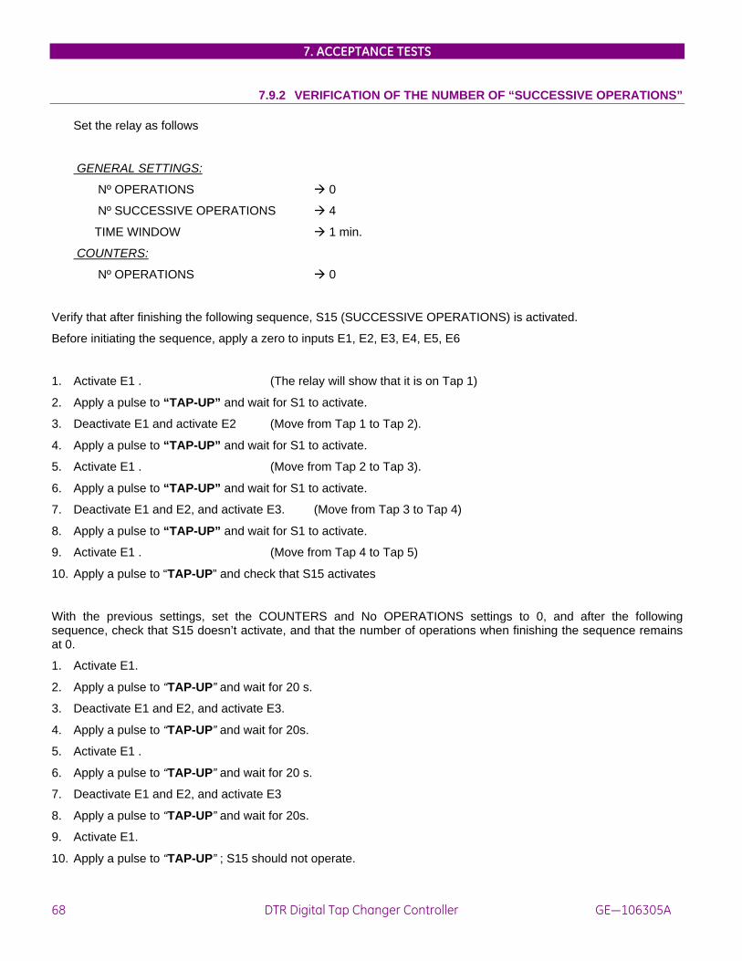
7. ACCEPTANCE TESTS
68 DTR Digital Tap Changer Controller GE—106305A
7.9.2 VERIFICATION OF THE NUMBER OF “SUCCESSIVE OPERATIONS”
Set the relay as follows
GENERAL SETTINGS:
Nº OPERATIONS 0
Nº SUCCESSIVE OPERATIONS 4
TIME WINDOW 1 min.
COUNTERS:
Nº OPERATIONS 0
Verify that after finishing the following sequence, S15 (SUCCESSIVE OPERATIONS) is activated.
Before initiating the sequence, apply a zero to inputs E1, E2, E3, E4, E5, E6
1. Activate E1 . (The relay will show that it is on Tap 1)
2. Apply a pulse to “TAP-UP” and wait for S1 to activate.
3. Deactivate E1 and activate E2 (Move from Tap 1 to Tap 2).
4. Apply a pulse to “TAP-UP” and wait for S1 to activate.
5. Activate E1 . (Move from Tap 2 to Tap 3).
6. Apply a pulse to “TAP-UP” and wait for S1 to activate.
7. Deactivate E1 and E2, and activate E3. (Move from Tap 3 to Tap 4)
8. Apply a pulse to “TAP-UP” and wait for S1 to activate.
9. Activate E1 . (Move from Tap 4 to Tap 5)
10. Apply a pulse to “TAP-UP” and check that S15 activates
With the previous settings, set the COUNTERS and No OPERATIONS settings to 0, and after the following sequence, check that S15 doesn’t activate, and that the number of operations when finishing the sequence remains at 0.
1. Activate E1.
2. Apply a pulse to “TAP-UP” and wait for 20 s.
3. Deactivate E1 and E2, and activate E3.
4. Apply a pulse to “TAP-UP” and wait for 20s.
5. Activate E1 .
6. Apply a pulse to “TAP-UP” and wait for 20 s.
7. Deactivate E1 and E2, and activate E3
8. Apply a pulse to “TAP-UP” and wait for 20s.
9. Activate E1.
10. Apply a pulse to “TAP-UP” ; S15 should not operate.

7. ACCEPTANCE TESTS
GEK-106305A DTR Digital Tap Changer Controller 69
8. INSTALLATION AND MAINTENANCE
8.1 INSTALLATION The relay should be installed in a clean, dry and dust-free place, with no vibrations. It should also be well-lit to facilitate inspection and testing.
The relay should be mounted on a vertical surface. Figure 3 shows the diagram for panel drilling for panel mounting.
Given that the design of the DTR unit is based on high performance digital technology it is not necessary to recalibrate the relay. However if the tests show that it is necessary to readjust the relay, it is recommended that the unit should be returned to the manufacturer to have this done.
8.2 CONNECTION TO GROUND AND SUPPRESSION OF DISTURBANCES Terminal A12 (see figure 1) should be connected to ground so that the disturbance suppression circuits in the system work correctly. This connection should be as short as possible (preferably 25 cm or less) to guarantee maximum protection. In this way the capacitors which are internally connected between the inputs and ground divert high frequency disturbances directly to ground without passing through the electronic circuits, with the result that the circuits are perfectly protected.
In addition this connection also guarantees the physical safety of the personnel who have to touch the relay, since the whole casing is connected to ground.
8.3 MAINTENANCE
Given the important role that the protection relays play in the operation of any installation, a periodical program of tests is highly recommended. The unit incorporates built-in diagnostic functions which permit immediate identification with only the aid of the keyboard and display, the detection of some of the most likely circuit failures. Testing the unit is recommended at intervals of 2 years or more. Although the built-in diagnosis does not reduce the average time between failures, it does increase the availability of the protection because it allows a drastic reduction in the average interruption time involved in detecting and repairing the fault.
The set of tests which can be carried out to test that all the features of the DTR unit function properly is described in detail in the chapter entitled ACCEPTANCE TESTS.
Since most of the protection and communications functions are integrated in two separate programs, it is unlikely that faults will occur due to problems of wear or aging which are typical in electromechanical, analog or hybrid protection systems. Moreover, a failure in the communications processor does not affect the protection functions, which are implemented by a dedicated processor.

8. INSTALLATION AND MAINTENANCE
70 DTR Digital Tap Changer Controller GE—106305A

9. KEYPAD AND DISPLAY
GEK-106305A DTR Digital Tap Changer Controller 71
9. KEYPAD AND DISPLAY The DTR incorporates a 20-key keypad and a liquid crystal display of 32 characters, divided in 2 lines of 16 characters each. The look of the DTR keypad is shown below:
SET 1/Y 2 3/N CLR INF 4 5 6 ACT 7 8 9 END +/- 0 . ENT
The keypad program uses menus to access the different relay functions. These functions have been divided into five groups, each of which can be accessed with a different key. The groups are as follows:
Information : Provides information about the relay status. This menu is accessed by pressing the INF key.
Operations : This menu allows to:
- synchronize the relay date and time
- Tap-up.
- Tap-down.
- Switch the regulator to manual mode.
- Switch the regulator to Automatic mode.
- Stop the regulator.
- Trigger the communications.
This menu is accessed by pressing the ACT key.
Settings : This menu allows to view and modify all the relay settings. This menu is accessed pressing the SET key.
Configuration Menu: Allows to access the relay configuration, and modify passwords, access levels, baudrates, etc. It can be accessed by dialing a password, “7169”. In order to access this menu, the relay must be displaying the main screen.
Single-key menu : DTR UNITS allow to use a simplified operation mode by pressing the ENT key. It is not necessary to remove the plastic cover on the front to access this mode.

9. KEYPAD AND DISPLAY
72 DTR Digital Tap Changer Controller GE—106305A
When in stand-by , the DTR displays the following message :
DTR
GENERAL ELECTRIC Here, we can select one of the five mentioned groups. For selecting a different group, we need to return to this display and then press the corresponding key.
Once inside a group, we cannot select another group without exiting and going back to the stand-by screen. We can move inside a group using ENT, CLR, ↑, ↓, ← & → keys. They are used as follows:
ENT : Accept the option that is on the display in that moment. It is the same as descending one level in the menu tree.
CLR : Exit the option on the display. It is the same as ascending one level in the menu tree.
↑/↓: Change option. It is the same as a horizontal movement inside a menu. When we find the desired option, we can select it with ENT.
←/→: These keys show the different possibilities of a certain setting. When we find the desired option, we can select it using ENT.
9.1 MENU TREE The DTR has different menus divided in levels. Level 0 is the stand-by screen. For accessing Level 1, we must press the key corresponding to a group (SET, INF, etc.). Inside a level, we can move using keys. For descending to Levels 2 and 3, we must press the ENT key. For ascending inside the menu tree, we must press the CLR key. At Level 1, the menus are as follows, depending on the selected group:
Group Level 1 Description SET
SEE PROTECTION SETTINGS
• See settings
• MODIFY PROTECTION SETTINGS
• Modify settings
INF • STATUS • Displays all the relay statuses ACT • SET DATE/TIME • Sets the relay date/time REMOTE TRIP
TAP-DOWN • Remote trip command • Tap decreasing command
TAP-UP • Tap increasing command MANUAL
REGULATOR • Command for switching to Manual mode
AUTOMATIC REGULATOR
• Command for switching to Automatic mode
STOP REGULATOR • Command for stopping the regulator • COMMUNICATIONS
TRIGGER • Triggers a log by communications
ENT • Current • Displays the Phase A current in amperes referred to the primary side

9. KEYPAD AND DISPLAY
GEK-106305A DTR Digital Tap Changer Controller 73
Group Level 1 Description • V-primary • Displays the phase voltage in kV referred to
the primary side • Frequency • Displays the frequency value • Tap • Displays the tap position of the OLTC RELAY STATUS • Shows whether the unit is in/out of service • ACTIVE TABLE • Shows which setting table is active • STOPPED • Displays the regulator status • AUTOMATIC • Displays the regulator status • REMOTE • Displays the regulator status • DATE/TIME • Displays the relay date/time 7169 • BAUDRATE • Remote baudrate • NET-STOP BITS • Stop bits of the remote communication • LOC-BAUDRATE • Local communication baudrate • LOC STOP BITS • Stop bits for the local communication • LOCAL SETTINGS • Allows the settings modification in local
mode • REMOTE
SETTINGS • Allows the settings modification in remote
mode • LOCAL
OPERATIONS • Allows to command operations in local
mode • REMOTE
OPERATIONS • Allows to command operations in local
mode • UNIT NUMBER • Unit number of the relay • PASSWORD • Relay password • t TIMEOUT • Maximum external synchronization time for
avoiding the generation of a timeout event

9. KEYPAD AND DISPLAY
74 DTR Digital Tap Changer Controller GE—106305A
9.2 SETTINGS GROUP This group allows to see and modify the DTR settings. It can be accessed by pressing the SET key when the DTR is in standby. By doing so, we will see the following message:
SEE PROTECTION
SETTINGS
By pressing the arrow keys, we see the message::
MODIFY
PROTECTION SETTINGS The menu tree for the DTR is shown in the table below. It is important to remark that if we want to descend down the tree, we must press ENT, and for ascending we must press CLR.
Level 1 Level 2 Level 3 Description Valid Range SEE PROTECTION SETTINGS
GENERAL SETTINGS
RELAY STATUS Used for turning the relay in service or out of service
In service / Out of service
• MODIFY PROTECTION SETTINGS
IDENTIFICATION 20-character alphanumerical chain
FREQUENCY Rated frequency 50/60 Hz VT RATIO
VT transformation ratio 1 - 4000 in steps of 1
CT RATIO
CT transformation ratio 1 - 4000 in steps of 1
ACTIVE TABLE Active settings table 1 – 3 ALGORITHM Type of regulation
algorithm 1=VOLTAGE; 2=COUNTING
RATED VOLTAGE Relay rated voltage 50 – 210 Vac in steps of 1 Vac
RATED CURRENT Relay rated current 1 / 5 A OPERATIONS NUM Maximum number of
operations 0 – 65535 (0=out of service)
# OP / T LIMIT Maximum number of operations within a time window
0 – 60 (0=out of service)
TIME WINDOW Time window length 1 – 60 min MINIMUM TAP OLTC minimum tap 1 - 40 MAXIMUM TAP OLTC maximum tap 1 – 40 DIR/INV MODE Tap Operation mode DIR / INV TT CONFIGURATION

9. KEYPAD AND DISPLAY
GEK-106305A DTR Digital Tap Changer Controller 75
Tabulated settings (repeated in 3 tables, selectable by digital input or communications)
Level 1 Level 2 Level 3 Description Valid Range REGULATION
SETTINGS T1 (TABLE 1)
INSENSITIVITY DEGREE
Insensitivity degree 0.5 – 5% Vn
Note: this group is repeated for tables 2 and 3
TIME FACTOR
Multiplier for operation time
1 - 100
FAST TAP-DOWN Voltage withstand for accelerated tap-down
110 – 150% Vn
I COMP FACTOR Current compensation factor
0 – 10% Vn
MAX COMPENSATION
Maximum elevation per compensation
3 – 15% Vn
BLOCKING SETTINGS T1 (TABLE 1)
OVERVOLTAGE Blocking level by overvoltage
110 – 180% Vn
Note: this group is repeated for tables 2 and 3
UNDERVOLTAGE Blocking level by undervoltage
0 – 90% Vn
OVERCURRENT Blocking level by overcurrent
0 – 200% Vn
TIMERS T1 (TABLE 1)
OPERATION PULSE
Output pulse duration for increasing/decreasing commands
0,02 – 60,00 s
Note: this group is repeated for tables 2 and 3
SUCCESS TIME Maximum reception time for the new tap position, after the tap-up / tap-down command
0,02 – 60,00 s
SETPOINT T1 (TABLE 1)
VOLTAGE SETPOINT
Voltage reference value
80 – 120% Vn
Note: this group is repeated for tables 2 and 3

9. KEYPAD AND DISPLAY
76 DTR Digital Tap Changer Controller GE—106305A
The DTR incorporates a setting group that is common to all tables, and other specific for each setting table.
The rest of setting groups is applicable to each table independently; there are different groups for each table.
In order to modify a setting, we must follow these steps:
1. Press the SET key
2. Select the MODIFY SETTINGS option.
3. Select the desired setting inside the menu tree.
4. Enter the value to be modified (or select the desired value from the available list using ← → ).
5. Press the ENT key. If we wish to modify another setting inside the same group, repeat steps 3 to 5.
6. Press the END key
The relay will ask for confirmation, displaying the following message:
CONFIRM?
(Y/N)
7. Press 1/Y to confirm the change. ( otherwise, press 3/N).
8. The relay will then display the following message:
SETTINGS CHANGE
EXECUTED 7. Press CLR repeatedly to return to stand-by status.
If a limit is exceeded when entering the setting value, the relay will not accept the change, and will display the following message:
SETTING OUT
OF RANGE Some settings do not require the user to enter a numerical value, but they offer a choice of options instead. In these cases, the different options can be viewed using ←/→.
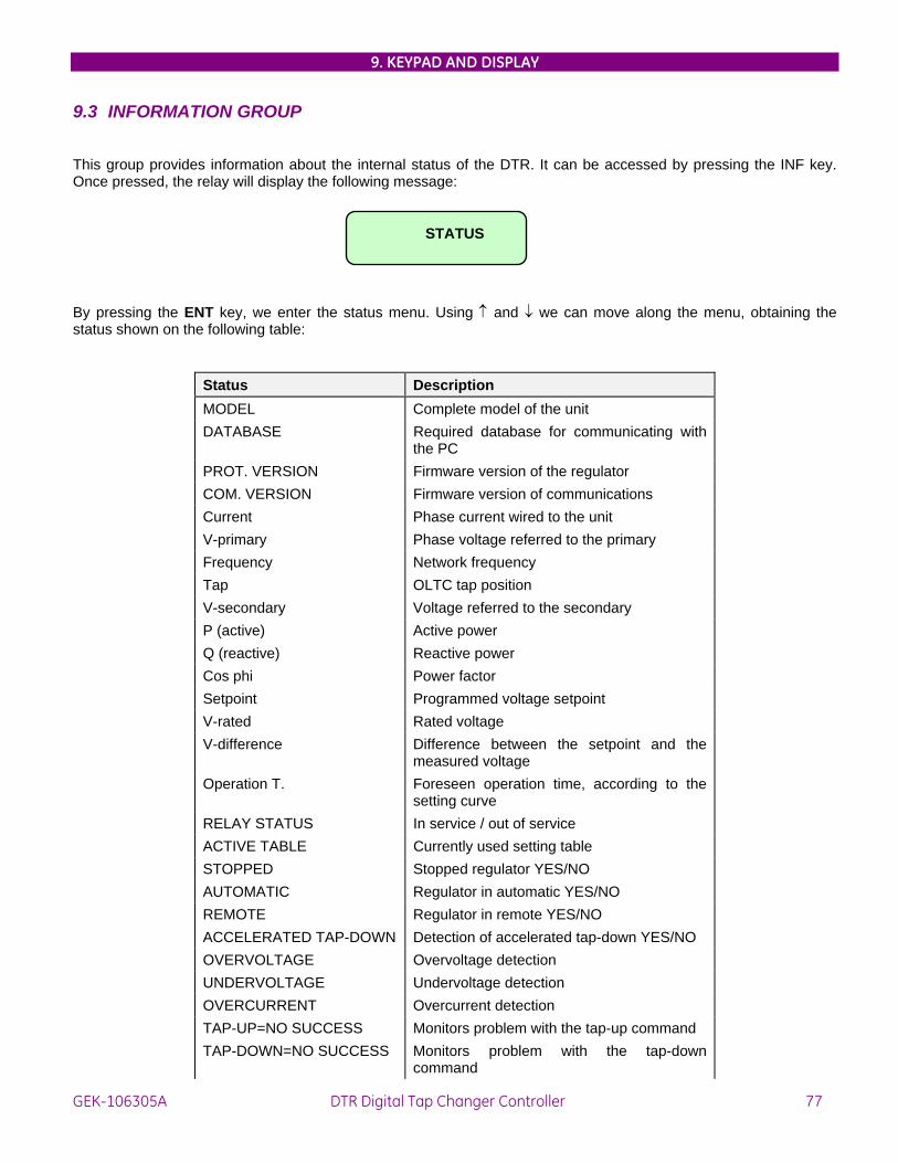
9. KEYPAD AND DISPLAY
GEK-106305A DTR Digital Tap Changer Controller 77
9.3 INFORMATION GROUP
This group provides information about the internal status of the DTR. It can be accessed by pressing the INF key. Once pressed, the relay will display the following message:
STATUS
By pressing the ENT key, we enter the status menu. Using ↑ and ↓ we can move along the menu, obtaining the status shown on the following table:
Status Description MODEL Complete model of the unit DATABASE Required database for communicating with
the PC PROT. VERSION Firmware version of the regulator COM. VERSION Firmware version of communications Current Phase current wired to the unit V-primary Phase voltage referred to the primary Frequency Network frequency Tap OLTC tap position V-secondary Voltage referred to the secondary P (active) Active power Q (reactive) Reactive power Cos phi Power factor Setpoint Programmed voltage setpoint V-rated Rated voltage V-difference Difference between the setpoint and the
measured voltage Operation T. Foreseen operation time, according to the
setting curve RELAY STATUS In service / out of service ACTIVE TABLE Currently used setting table STOPPED Stopped regulator YES/NO AUTOMATIC Regulator in automatic YES/NO REMOTE Regulator in remote YES/NO ACCELERATED TAP-DOWN Detection of accelerated tap-down YES/NO OVERVOLTAGE Overvoltage detection UNDERVOLTAGE Undervoltage detection OVERCURRENT Overcurrent detection TAP-UP=NO SUCCESS Monitors problem with the tap-up command TAP-DOWN=NO SUCCESS Monitors problem with the tap-down
command

9. KEYPAD AND DISPLAY
78 DTR Digital Tap Changer Controller GE—106305A
Status Description INTERLOCKING-1 Interlocking-1 input activation INTERLOCKING-2 Interlocking-2 input activation SUCCESSIVE OPERATIONS
Successive operations number detection
MAXIMUM TAP Monitors if the maximum tap has been reached.
MINIMUM TAP Monitors if the minimum tap has been reached
REGULATOR ALARM Alarm input activation IRREGULAR CHANGE Detection of irregularities in the change EXCESSIVE OP. Monitors if there has been an excessive
number of tap-up/tap-down operations. LOCAL CONNECT Monitors whether the connection is
local/remote DATE/TIME Monitors whether the relay date/time is
reliable COMM E2PROM Informs of a detected error in the
communications EEPROM COMM SETTINGS Shows whether the communication settings
are the default or the user’s. PROTECTION LINK Monitors the communication between the
protection CPU and the communications CPU
IRIG-B LINK Monitors the reception of the IRIG-B satellite synchronization signal
DATE AND TIME Displays the relay date/time

9. KEYPAD AND DISPLAY
GEK-106305A DTR Digital Tap Changer Controller 79
9.4 OPERATIONS GROUP This group allows to set the relay date and time, as well as increasing/decreasing the tap, switching to Manual / Automatic mode, stop the regulator or trigger an event.
For accessing the operations group, we must press the ACT key from the stand-by screen:
For modifying the date/time, follow the steps below:
DTR ACT SET ENT YEAR GENERAL ELECTRIC DATE/TIME 02 ENT MONTH ENT DAY ENT TIME 02 09 10 ENT MINUTE ENT SECOND ENT 09-02-2002 20 30 10:20:30 NOTE : For modifying the numerical value displayed by default, press the CLR key for deleting the current value.
The execution of the COMMUNICATIONS TRIGGER command will cause the relay to issue an event.

9. KEYPAD AND DISPLAY
80 DTR Digital Tap Changer Controller GE—106305A
9.5 SINGLE-KEY OPERATION. The DTR incorporates a simplified operation mode, using only the ENT key. This mode allows to access relay information without the need to remove the external plastic cover. The operation mode consists in pressing the ENT key repeatedly. For accessing this mode, we need to start at the stand-by message. The available information in this operation mode is as follows:
Current Displays the Phase A current in amperes, referred to the primary side.
V-primary Displays the phase voltage in kV, referred to the primary side.
Frequency Displays the actual frequency value
Tap Displays the OLTC tap position
RELAY STATUS
Indicates whether the relay is in service or out of service
ACTIVE TABLE Indicates which is the active settings table
STOPPED Displays the regulator status
AUTOMATIC Displays the regulator status
REMOTE Displays the regulator status
DATE/TIME Displays the relay date and time

9. KEYPAD AND DISPLAY
GEK-106305A DTR Digital Tap Changer Controller 81
9.6 CONFIGURATION MENU
DTR units incorporate a configuration unit that can only be accessed through the relay keypad. Its objective is to select how the DTR unit will interact with external elements.
The configuration unit is accessed from the stand-by screen, by entering a 4-character code through the unit keypad. If the code is correct, the configuration unit is accessed; otherwise, we remain at the standby screen. The code is unique for DTR relays, as it does not intend to be a password, but a security measure to avoid accidental modification of the configuration. This code is 7169, which corresponds to the ASCII code of GE initials. Please refer to the example below:
DTR 7 1 GENERAL ELECTRIC * ** 6 9 NET BAUDRATE *** The settings value and their meaning are detailed below. It is important to remark that inside this group, we can move using the ↑/↓ keys.
• NET BAUDRATE : Is the baudrate used by the DTR in serial communications with the remote controller. The possible baudrate range is 1200 to 19200 bauds.
• NET STOP BITS : is the number of stop bits added to each byte transmitted via the serial line. This setting is treated as a binary logic setting, selected by the logic key 1/Y for 1, and 3/N for 2.
• LOC BAUDRATE: Is the baudrate used by the DTR in serial communications with the local controller. The possible baudrate range is 1200 to 19200 bauds.
• LOC STOP BITS: Same setting as in the remote case, but referred to local communications.
• LOCAL SETTINGS: This setting enables/disables the setting change through local communications.
• REMOTE SETTINGS: This setting enables/disables the setting change through remote communications.
• LOCAL OPERATIONS: This setting enables/disables the feature of commanding operations locally.
• REMOTE OPERATIONS: This setting enables/disables the feature of commanding operations remotely.
• UNIT NUMBER: Each DTR is identified by a unit number, used for identifying messages addressed to each unit when there are several units connected to the same communications line. This number can be any between 1 and 255, both inclusive.
• PASSWORD: In order to avoid undesired communication with the relay through GE-LOCAL communications software, DTR units incorporate a password. This password can only be seen from the relay display and is a number between 0 and 99999. The password entered in GE-LOCAL must match the unit password for enabling communication.
• t TIMEOUT: Maximum external synchronization time for avoiding a timeout event.

9. KEYPAD AND DISPLAY
82 DTR Digital Tap Changer Controller GE—106305A

FIGURES
GEK-106305A DTR Digital Tap Changer Controller 83
FIGURE LIST
Fig.1 : External connections for DTR units with taps coded in BCD
Fig. 2 : External connections for DTR units with taps per contact.
Fig. 3 : Panel mounting diagram
Fig. 5 : RS-232 connection
Fig. 6 : Dimensions diagram
Fig. 7 : Front view
Fig. 8 : Rear view

FIGURES
84 DTR Digital Tap Changer Controller GE—106305A
FIGURE 1 : WIRING DIAGRAM FOR DTR UNITS WITH TAPS CODED IN BCD
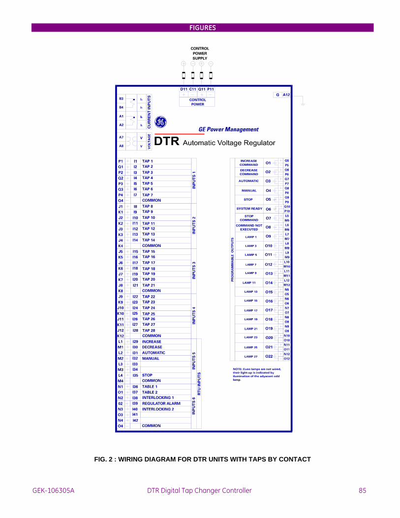
FIGURES
GEK-106305A DTR Digital Tap Changer Controller 85
FIG. 2 : WIRING DIAGRAM FOR DTR UNITS WITH TAPS BY CONTACT

FIGURES
86 DTR Digital Tap Changer Controller GE—106305A
FIGURE 3 : PANEL MOUNTING DIAGRAM

FIGURES
GEK-106305A DTR Digital Tap Changer Controller 87
FIGURE 4. RS-232 CONNECTION

FIGURES
88 DTR Digital Tap Changer Controller GE—106305A
FIGURE 5 : DIMENSIONS DIAGRAM

FIGURES
GEK-106305A DTR Digital Tap Changer Controller 89
FIGURE 6 : FRONT VIEW

FIGURES
90 DTR Digital Tap Changer Controller GE—106305A
FIGURE 8 : GENERIC REAR VIEW