ge aes greenhouse gas services · pdf filege aes greenhouse gas services will review the...
TRANSCRIPT
GE AES Greenhouse Gas Services
Methodology for Landfill Gas Methane Capture and Destruction Projects
Version 1.1 – November 10, 2008
NOTES TO USERS:
Please check that you are using the most current version of this Methodology.
GE AES Greenhouse Gas Services will review the Methodology on an annual basis, and
may make non-substantive edits from time to time as appropriate.
This Methodology contains procedures to quantify emissions reductions from capture and
destruction of methane. Sections related to displacement credits are under separate general
methodologies.
For Information, Comments or Questions – Please Send Electronic Mail to:
GE AES Greenhouse Gas Services - Landfill Gas Methodology
Version 1.1 (November 10, 2008) Page 2 of 47
Content
1 Summary and Applicability of Methodology................................................................. 4 1.1 Methodology Description........................................................................................ 4 1.1.1 Purpose and Objectives ...................................................................................... 4
1.1.2 Projects that can utilize this methodology ......................................................... 5 1.1.3 Relevant GHG Methodologies and Standards.................................................. 5 1.1.4 Relevant Technical Codes, Standards, and Guidelines.................................... 6 1.1.5 Relevant Legal Authorities and Regulations ...................................................... 6
2 Eligibility criteria for each Scenario in this Methodology............................................... 9
3 Methodology Structure .................................................................................................. 11 4 Terms and Definitions...................................................................................................... 12 4.1 Emission Guidelines (EG)........................................................................................ 12 4.2 Landfill gas (LFG) .................................................................................................... 12 4.3 Municipal Solid Waste (MSW) Landfills.................................................................. 12
4.4 National Emission Standards for Hazardous Air Pollutants (NESHAP).................. 12 4.5 Non-methane organic compounds (NMOC)...................................................... 12 4.6 New Source Performance Standards (NSPS) ....................................................... 12 4.7 Resource Conservation and Recovery Act (RCRA) ............................................ 12
5 Description of Scenarios and Identification of SSRs..................................................... 13
5.1 Descriptions of Scenarios....................................................................................... 13 5.2 Identifying the Sources, Sinks and Reservoirs (SSRs) Relevant to the Scenarios 15 5.2.1 Controlled and Related SSRs............................................................................. 16 5.2.2 Affected SSRs (Leakage) ................................................................................... 19
5.3 Selecting GHG SSRs for monitoring or estimating GHG emissions ...................... 19 6 Determining the Baseline Scenario ............................................................................... 21
6.1 Considerations for Selecting the Baseline Scenario ............................................ 21 6.1.1 Project Accounting for Destruction of Methane Only..................................... 21 6.1.2 Projects Accounting for Destruction of Methane and Displacement of
Energy 22 7 Greenhouse Gas Quantification ................................................................................... 23
7.1 Controlled and Related SSRs................................................................................. 23 7.1.1 SSR 3 – Compression, Blower and Gathering System for landfill gas Capture23 7.1.2 SSR 5 – Flare Operation ...................................................................................... 23 7.1.3 SSR 7 – Boiler or other combustion device ....................................................... 24 7.1.4 SSR 8 - Engine, turbine or other electrical generating unit.............................. 25
GHG reductions attributable to displaced grid electricity consumption are
addressed in this methodology but require the GHGS methodology titled
Quantification Methodology for Displacement Projects. ........................................... 26 8 Monitoring ....................................................................................................................... 27 8.1 Simple Monitoring Plan .......................................................................................... 27
8.1.1 Determination of Methane Flow Rate .............................................................. 27 8.1.2 Determination of Combustion Efficiency ......................................................... 30
8.2 Advanced Monitoring ........................................................................................... 31 8.2.1 Determination of Methane Flow Rate .............................................................. 31 8.2.2 Advanced Combustion Efficiency.................................................................... 32
8.3 Monitoring Plan....................................................................................................... 35 9 QA/QC and Data Management.................................................................................. 41

GE AES Greenhouse Gas Services - Landfill Gas Methodology
Version 1.1 (November 10, 2008) Page 3 of 47
9.1 Recordkeeping procedures.................................................................................. 41 10 Emission Reduction Quantification ............................................................................... 43 10.1 Methane Destruction Projects............................................................................... 43
10.2 Displacement Projects Electrical........................................................................... 44 10.3 Displacement Projects Thermal............................................................................. 44
11 Documentation and Reporting..................................................................................... 44 ANNEX A – State-level Greenhouse Gas Emission Factors for Electricity Generation ...... 46
GE AES Greenhouse Gas Services - Landfill Gas Methodology
Version 1.1 (November 10, 2008) Page 4 of 47
1 Summary and Applicability of Methodology
This document establishes a methodology for the quantification of greenhouse gas (GHG)
emission reductions, or credits from eligible landfills. These GHG credits are based on metric
tonnes of CO2e, a standardized measure of GHG measurement. This protocol will be used by
project developers to bring GHG credits from eligible landfills in the United States and in other
locations, to market and make the reductions relevant and transferable to other major GHG
markets.
1.1 Methodology Description
1.1.1 Purpose and Objectives
Concern over climate change due to increasing levels of GHG’s in the atmosphere has led to
evaluation of different methods to reduce GHG emissions. According to the U.S. Environmental
Protection Agency (USEPA)1 , methane from municipal solid waste landfills is the largest source
of human-made methane in the U.S., contributing approximately 25% to the total amount of
methane emitted. Landfill gas typically contains 50% methane and 50% carbon dioxide and
other trace compounds. Given that the Intergovernmental Panel on Climate Change (IPCC)
estimates that methane has a global warming potential (GWP) of 21-25 times that of carbon
dioxide, the reduction of methane emission can provide significant reduction of total GHG
emissions2,3,4
.
The collection and control of landfill gas (LFG) in the U.S. is a proven practice and is required
for many landfills by the New Source Performance Standards (NSPS) under 40 CFR 60 Subpart
WWW. These landfills are required to collect and control the landfill gas via flaring, use in a
combustion device such as an engine or boiler, or treat the landfill gas to remove particulate and
moisture before using the treated LFG as a fuel. Landfills that are required to collect and control
LFG under the NSPS are not considered to be eligible candidates for GHG credits since methane
control is achieved through the required incineration of non-methane organic compounds
contained in the LFG. Therefore, methane and GHG emission reductions from NSPS-regulated
facilities operating under regulatory requirements are not voluntary. However, many small and
medium sized landfills are not required to collect and control LFG. In addition, facilities can
install LFG collection systems and collect gas prior to the date or stage at which collection
requirements apply (pre-regulation – see Section 2.1, below – during the 30 months following
the date on which the NMOC emissions from the landfill exceed 50 Mg/year). Voluntary
reductions of methane and GHG’s credits from these sites and under these circumstances could
be monetized through GHG markets.
Additionally, the use of LFG to generate electricity or provide thermal energy can displace the
use of fossil fuels. The displacement of such fossil fuels also provides a quantifiable level of
GHG reductions.
1 Inventory of U.S. Greenhouse Gas Emissions and Sinks: 1990-2004. U.S.E.P.A. #430-R-06-002 2 IPCC Second Assessment Report: Climate Change 1996 3 IPCC Third Assessment Report: 2001 4 IPCC Fourth Assessment Report: 2007

GE AES Greenhouse Gas Services - Landfill Gas Methodology
Version 1.1 (November 10, 2008) Page 5 of 47
Since voluntary reductions of methane from LFG combustion or energy generation using LFG
can be monetized in GHG markets, a methodology is necessary to determine eligible landfills,
measure the amount of methane destroyed, energy produced, keep records, and validate these
GHG credits. This protocol must have sufficient environmental and scientific integrity to
provide accurate and verifiable emission reduction measurements.
1.1.2 Projects that can utilize this methodology
Before GHG credits can be developed from a methane destruction project at a landfill, each
landfill must be evaluated to determine if emission reductions are considered to be voluntary and
not the result of any Federal, State, or Local regulatory requirements and whether the gas
collection and control system installation date falls within the scope of the Standard of Practice.
While many regulatory programs for landfills require equipment and processes similar to those
used to achieve voluntary reductions and essentially achieve the same level of GHG reductions,
the Standard of Practice standard does not consider GHG reductions achieved under a regulatory
framework to meet the voluntary criteria for this protocol. Essentially, qualifying GHG emission
reduction activities at landfills must represent reductions that are achieved outside of those
achieved by existing regulatory drivers.
This methodology also contemplates the operation of energy projects utilizing methane captured
under this methodology. GHG reductions attributable to displaced natural gas or grid
electricity consumption are addressed in this methodology but require the GHGS methodology
titled Quantification Methodology for Displacement Projects. These projects can be based on
the use of LFG collected voluntarily or LFG required for collection under Federal, State, or
Local regulatory requirements. Since these regulations address the destruction of non-methane
organic compounds, they do not prescribe that landfills use energy projects to achieve
compliance. Therefore, the Standard of Practice will consider the GHG reductions achieved via
the displacement of fossil fuels used for electrical or thermal energy generation.
Operational activities for projects or activities creating credits must have commenced after
January 1, 2000, and credits-generating activity will only be certifiable for activity started after
January 21, 2002. Additionally, demonstration of ownership rights of the LFG must be
demonstrated. For most recently developed LFG projects in operation, LFG rights are clearly
outlined in any contractual agreement between the landfill, end-users, and/or third-parties. In
some cases, landfills may enter into contracts with other parties and sell the rights to the LFG
without actually having an LFG collection and control project in place.
1.1.3 Relevant GHG Methodologies and Standards
The development of this methodology included review of several different existing or proposed
GHG methodologies in order to evaluate the various aspects of these methodologies that meet
the overall principles and requirements of the Standard of Practice. This evaluation included the
review of the following methodologies:
1. Standard of Practice for GHG Credits

GE AES Greenhouse Gas Services - Landfill Gas Methodology
Version 1.1 (November 10, 2008) Page 6 of 47
2. Clean Development Mechanism, Annex 13, “Methodological tool to determine project
emissions from flaring gases containing methane.”
3. U.S. EPA Climate Leaders, Draft Offset Protocol, Project Type: Landfill Methane
Collection and Combustion, October 2006.
4. Protocol for Measuring and Verifying Greenhouse Gas Reductions from Landfills,
Chicago Climate Exchange.
5. ISO 14064-2:2006 GHG Project Standard
6. WRI/WBCSD GHG Projects Protocol
7. Clean Development Mechanism. Approved consolidated baseline methodology
ACM0001. “Consolidated baseline and monitoring methodology for landfill gas project
activities.”
Overall, this methodology incorporates similar elements for determining GHG credits from
landfill gas projects such as measuring landfill gas flow to a combustion device and monitoring
combustion device operation. This approached was adopted in order to develop a methodology
that will facilitate a voluntary trading market but provide sufficient documentation to ensure the
credibility of the GHG credits delivered to the market.
1.1.4 Relevant Technical Codes, Standards, and Guidelines
Existing U.S. regulations that address landfill gas and NOx/SO2 emission trading programs were
reviewed and considered in the development of this methodology. These regulations included 40
CFR 60 Subpart WWW (Landfill NSPS) and 40 CFR Part 75 (Continuous Emission Monitoring
procedures to establish requirements for the monitoring, recordkeeping, and reporting of sulfur
dioxide (SO2), nitrogen oxides (NOX), and carbon dioxide (CO2) emissions, volumetric flow, and
opacity data from affected units under the Acid Rain Program, including gas and oil-fired
turbines). Some of the monitoring provisions outlined in the landfill NSPS were incorporated as
landfill owners and operators will already be familiar with these requirements, in addition to
many of the equipment suppliers that work with these sources. Additionally, aspects of the
reduced monitoring options outlined in 40 CFR 75 that are applicable to gas and oil-fired
turbines were incorporated into this methodology. Since EPA has already evaluated and
approved some of these monitoring methodologies for existing cap-and-trade programs, the
credibility of these requirements has already been established. Furthermore, vendors of the data
acquisition and handling systems that would be used to calculate emission reductions are already
familiar with many of the requirements and algorithms contained in this methodology. This
should result in reduced cost in designing and operating data acquisition and handling systems
needed to manage the data for this methodology.
1.1.5 Relevant Legal Authorities and Regulations
1.1.5.1 Existing Regulatory Programs for Landfills
Landfills are regulated by several EPA standards regarding solid waste disposal (Subtitle D
requirements) and air emissions, along with many state and local environmental and zoning
requirements. These regulations must be observed by landfill owners and operators and nothing
in this protocol absolves landfill owners and operators from observing these regulations.

GE AES Greenhouse Gas Services - Landfill Gas Methodology
Version 1.1 (November 10, 2008) Page 7 of 47
Emission control requirements for landfills exist under several different regulatory programs.
The most common regulatory program that establishes an emission control requirement for
landfills is the New Source Performance Standard (NSPS) codified in 40 CFR 60 Subpart
WWW. Under the NSPS, landfills that have a design capacity that exceeds 2.5 million cubic
meters and 2.5 million megagrams and commenced construction, reconstruction, or modification
after May 30, 2007 are required to evaluate their non-methane organic compound (NMOC)
emission rate. If, based on the evaluation criteria outlined in the NSPS, the NMOC emission
from the landfill exceed 50 Mg/year, then the landfill has 30 months to install a landfill gas
collection and control system. For landfills that commenced construction, reconstruction, or
modification before May 30, 1991, the Emission Guidelines (EG) codified in 40 CFR 60 Subpart
Cc outlines similar applicability and control requirements as the NSPS. EPA also promulgated a
National Emission Standard for Hazardous Air Pollutants (NESHAP) for municipal solid waste
landfills on January 13, 2003 (see 40 CFR 63 subpart AAAA). This regulation requires gas
collection and controls systems based on the requirements in the NSPS, but may result in
different compliance schedules based on certain landfill characteristics.
For landfills considered for developing GHG credits, documentation of regulatory applicability
status is required by this protocol to demonstrate that any gas collection and control activities are
the result of voluntary actions and not in response to regulatory requirements. In some cases, the
entire gas collection and control system may be required by a specific regulation. However,
some sections of a gas collection and control system may be voluntary as a landfill may install
these systems before a specific compliance date. For the purposes of this protocol, installation of
a collection and control system in advance of a known compliance date can result in eligible
GHG credits. However, once the compliance date is reached, GHG credits are no longer
eligible. (see Section 2 of this methodology for eligibility criteria that must be provided with
project documentation)
1.1.5.2 Ownership of Gas Rights and Environmental Attributes
LFG projects in the U.S. include contractual agreements between the landfill and developers,
end-users, and other third-parties. These contractual agreements outline the ownership of the
LFG and any associated environmental attributes from the use of the LFG. Environmental
attributes include the potential GHG credits created from the combustion of unregulated LFG
and the generation of “green” electricity when the LFG is used to power electrical generating
systems. Sometimes, these LFG agreements are enacted even before any LFG collection
systems have been constructed at landfills. For the purposes of the Standard of Practice,
documentation of LFG ownership must be provided to demonstrate that the entity bringing the
GHG credits to market have legal ownership of the LFG and that the GHG credits will not be
used in other markets. For some LFG projects, two mechanisms exist for GHG credits. The first
is through the voluntary combustion of methane, and the second is from the offset of GHG
emissions from fossil fuels combustion when the LFG is used to generate electric or thermal
energy (e.g., boilers, kilns, process heaters). The Standard of Practice will allow a project to
bring GHG credits based on the destruction of methane to this market, and GHG credits resulting
from the displacement of fossil fuel use or alternative energy generation via the use of LFG to
another market in accordance with the GHGS methodology titled Quantification Methodology for
GE AES Greenhouse Gas Services - Landfill Gas Methodology
Version 1.1 (November 10, 2008) Page 8 of 47
Displacement Projects. Documentation of the ownership and fate of these attributes must be
clearly described and provided to demonstrate eligibility for GHG credits.
For example: Utilities in some states are required to generate a percentage of their overall
electrical supply from alternative energy sources, such as landfill gas based electrical generation
activities. In such an area, demand for green electricity may result in a premium value for
electricity generated by an LFG energy project. In such a case, the project developer may be
able to receive greater income by selling green energy on the grid versus selling the GHG credits
resulting from the displacement of fossil fuels under the Standard of Practice. However, the
project developer would still look to sell GHG credits from the destruction of methane under the
Standard of Practice. Such a scenario is allowed under this methodology. This approach is
allowed, provided, that the project developer does not violate the principle of uniqueness as
defined in the Standard of Practice.
GE AES Greenhouse Gas Services - Landfill Gas Methodology
Version 1.1 (November 10, 2008) Page 9 of 47
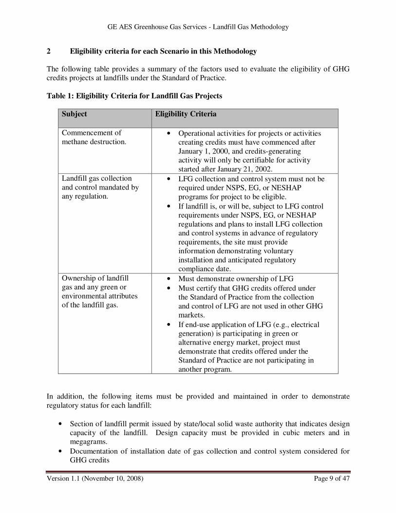
2 Eligibility criteria for each Scenario in this Methodology
The following table provides a summary of the factors used to evaluate the eligibility of GHG
credits projects at landfills under the Standard of Practice.
Table 1: Eligibility Criteria for Landfill Gas Projects
Subject Eligibility Criteria
Commencement of
methane destruction. • Operational activities for projects or activities
creating credits must have commenced after
January 1, 2000, and credits-generating
activity will only be certifiable for activity
started after January 21, 2002.
Landfill gas collection
and control mandated by
any regulation.
• LFG collection and control system must not be
required under NSPS, EG, or NESHAP
programs for project to be eligible.
• If landfill is, or will be, subject to LFG control
requirements under NSPS, EG, or NESHAP
regulations and plans to install LFG collection
and control systems in advance of regulatory
requirements, the site must provide
information demonstrating voluntary
installation and anticipated regulatory
compliance date.
Ownership of landfill
gas and any green or
environmental attributes
of the landfill gas.
• Must demonstrate ownership of LFG
• Must certify that GHG credits offered under
the Standard of Practice from the collection
and control of LFG are not used in other GHG
markets.
• If end-use application of LFG (e.g., electrical
generation) is participating in green or
alternative energy market, project must
demonstrate that credits offered under the
Standard of Practice are not participating in
another program.
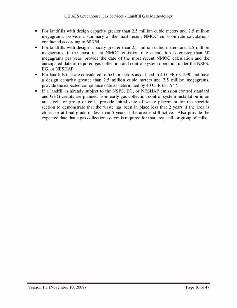
In addition, the following items must be provided and maintained in order to demonstrate
regulatory status for each landfill:
• Section of landfill permit issued by state/local solid waste authority that indicates design
capacity of the landfill. Design capacity must be provided in cubic meters and in
megagrams.
• Documentation of installation date of gas collection and control system considered for
GHG credits
GE AES Greenhouse Gas Services - Landfill Gas Methodology
Version 1.1 (November 10, 2008) Page 10 of 47
• For landfills with design capacity greater than 2.5 million cubic meters and 2.5 million
megagrams, provide a summary of the most recent NMOC emission rate calculations
conducted according to 60.754.
• For landfills with design capacity greater than 2.5 million cubic meters and 2.5 million
megagrams, if the most recent NMOC emission rate calculation is greater than 50
megagrams per year, provide the date of the most recent NMOC calculation and the
anticipated date of required gas collection and control system operation under the NSPS,
EG, or NESHAP.
• For landfills that are considered to be bioreactors as defined in 40 CFR 63.1990 and have
a design capacity greater than 2.5 million cubic meters and 2.5 million megagrams,
provide the expected compliance date as determined by 40 CFR 63.1947.
• If a landfill is already subject to the NSPS, EG, or NESHAP emission control standard
and GHG credits are planned from early gas collection control system installation in an
area, cell, or group of cells, provide initial date of waste placement for the specific
section to demonstrate that the waste has been in place less that 2 years if the area is
closed or at final grade or less than 5 years if the area is still active. Also provide the
expected date that a gas collection system is required for that area, cell, or group of cells.

GE AES Greenhouse Gas Services - Landfill Gas Methodology
Version 1.1 (November 10, 2008) Page 11 of 47
3 Methodology Structure
The following table presents the general structure of the methodology and refers the reader to the
specific section where each scenario is described and procedures for quantification, monitoring
and data management that the project developer may select.
In addition to the default scenarios, this methodology includes a section for determining the
appropriate baseline scenario, as well as the documentation and reporting requirements
Table 2: Methodology Structure
Structure Relevant Section
Scenario Description Section 5.1
Identification of Sources, Sinks & Reservoirs Section 5.2
Selecting relevant SSRs for Quantification Section 5.3
Determining the baseline scenario Section 6
Quantification Section 7
Simple Monitoring Section 8.1
Advance Monitoring Section 8.2
QA/QC Data Management Procedures Section 9
Emission Reduction Quantification Section 10
Documentation and Reporting Section 11
This protocol establishes two approaches in quantifying GHG credits resulting from the
destruction of methane from eligible landfills. The simplified approach prescribes less stringent
testing and monitoring provisions, but uses more conservative assumptions in the calculation of
GHG credits. Alternatively, the more advanced approach requires a higher level (and cost) of
testing and monitoring, but may allow eligible landfills to deliver greater GHG credits to the
market. These two options are allowed in order to provide greater flexibility for project
developers that wish to bring GHG credits to the market given that it is a voluntary market at this
time. In the development of the simple and advanced approached provided in this methodology,
the Standard of Practice has balanced the level of detail in monitoring requirements with the
degree of conservativeness in various calculations to ensure that GHG credits delivered under
each approach are equivalent from the standpoint of quantity and credibility.
GE AES Greenhouse Gas Services - Landfill Gas Methodology
Version 1.1 (November 10, 2008) Page 12 of 47
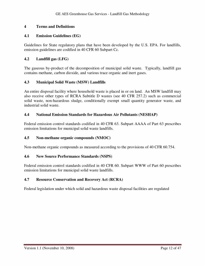
4 Terms and Definitions
4.1 Emission Guidelines (EG)
Guidelines for State regulatory plans that have been developed by the U.S. EPA. For landfills,
emission guidelines are codified in 40 CFR 60 Subpart Cc.
4.2 Landfill gas (LFG)
The gaseous by-product of the decomposition of municipal solid waste. Typically, landfill gas
contains methane, carbon dioxide, and various trace organic and inert gases.
4.3 Municipal Solid Waste (MSW) Landfills
An entire disposal facility where household waste is placed in or on land. An MSW landfill may
also receive other types of RCRA Subtitle D wastes (see 40 CFR 257.2) such as commercial
solid waste, non-hazardous sludge, conditionally exempt small quantity generator waste, and
industrial solid waste.
4.4 National Emission Standards for Hazardous Air Pollutants (NESHAP)
Federal emission control standards codified in 40 CFR 63. Subpart AAAA of Part 63 prescribes
emission limitations for municipal solid waste landfills.
4.5 Non-methane organic compounds (NMOC)
Non-methane organic compounds as measured according to the provisions of 40 CFR 60.754.
4.6 New Source Performance Standards (NSPS)
Federal emission control standards codified in 40 CFR 60. Subpart WWW of Part 60 prescribes
emission limitations for municipal solid waste landfills.
4.7 Resource Conservation and Recovery Act (RCRA)
Federal legislation under which solid and hazardous waste disposal facilities are regulated
GE AES Greenhouse Gas Services - Landfill Gas Methodology
Version 1.1 (November 10, 2008) Page 13 of 47
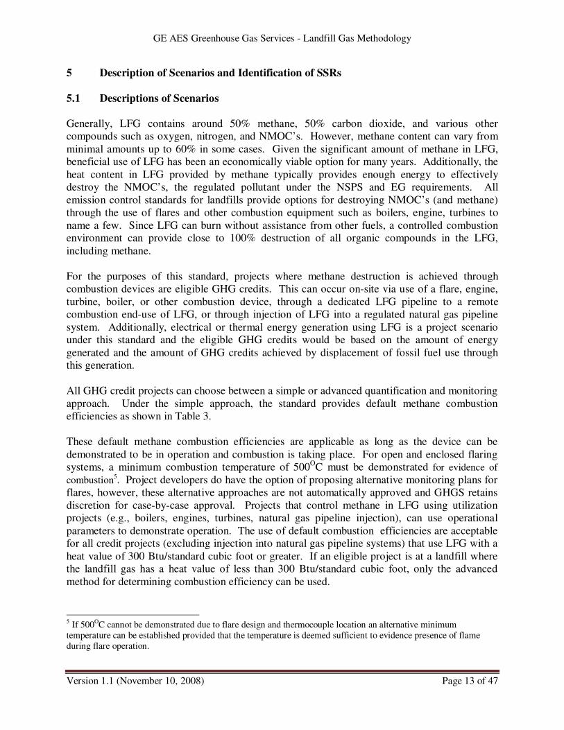
5 Description of Scenarios and Identification of SSRs
5.1 Descriptions of Scenarios
Generally, LFG contains around 50% methane, 50% carbon dioxide, and various other
compounds such as oxygen, nitrogen, and NMOC’s. However, methane content can vary from
minimal amounts up to 60% in some cases. Given the significant amount of methane in LFG,
beneficial use of LFG has been an economically viable option for many years. Additionally, the
heat content in LFG provided by methane typically provides enough energy to effectively
destroy the NMOC’s, the regulated pollutant under the NSPS and EG requirements. All
emission control standards for landfills provide options for destroying NMOC’s (and methane)
through the use of flares and other combustion equipment such as boilers, engine, turbines to
name a few. Since LFG can burn without assistance from other fuels, a controlled combustion
environment can provide close to 100% destruction of all organic compounds in the LFG,
including methane.
For the purposes of this standard, projects where methane destruction is achieved through
combustion devices are eligible GHG credits. This can occur on-site via use of a flare, engine,
turbine, boiler, or other combustion device, through a dedicated LFG pipeline to a remote
combustion end-use of LFG, or through injection of LFG into a regulated natural gas pipeline
system. Additionally, electrical or thermal energy generation using LFG is a project scenario
under this standard and the eligible GHG credits would be based on the amount of energy
generated and the amount of GHG credits achieved by displacement of fossil fuel use through
this generation.
All GHG credit projects can choose between a simple or advanced quantification and monitoring
approach. Under the simple approach, the standard provides default methane combustion
efficiencies as shown in Table 3.
These default methane combustion efficiencies are applicable as long as the device can be
demonstrated to be in operation and combustion is taking place. For open and enclosed flaring
systems, a minimum combustion temperature of 500OC must be demonstrated for evidence of
combustion5. Project developers do have the option of proposing alternative monitoring plans for
flares, however, these alternative approaches are not automatically approved and GHGS retains
discretion for case-by-case approval. Projects that control methane in LFG using utilization
projects (e.g., boilers, engines, turbines, natural gas pipeline injection), can use operational
parameters to demonstrate operation. The use of default combustion efficiencies are acceptable
for all credit projects (excluding injection into natural gas pipeline systems) that use LFG with a
heat value of 300 Btu/standard cubic foot or greater. If an eligible project is at a landfill where
the landfill gas has a heat value of less than 300 Btu/standard cubic foot, only the advanced
method for determining combustion efficiency can be used.
5 If 500OC cannot be demonstrated due to flare design and thermocouple location an alternative minimum
temperature can be established provided that the temperature is deemed sufficient to evidence presence of flame
during flare operation.
GE AES Greenhouse Gas Services - Landfill Gas Methodology
Version 1.1 (November 10, 2008) Page 14 of 47
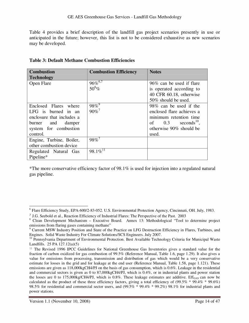
Table 4 provides a brief description of the landfill gas project scenarios presently in use or
anticipated in the future; however, this list is not to be considered exhaustive as new scenarios
may be developed.
Table 3: Default Methane Combustion Efficiencies
Combustion
Technology
Combustion Efficiency Notes
Open Flare 96%6,7
508%
96% can be used if flare
is operated according to
40 CFR 60.18, otherwise
50% should be used.
Enclosed Flares where
LFG is burned in an
enclosure that includes a
burner and damper
system for combustion
control.
98%9
90%7
98% can be used if the
enclosed flare achieves a
minimum retention time
of 0.3 seconds10
,
otherwise 90% should be
used.
Engine, Turbine, Boiler,
other combustion device
98%7
Regulated Natural Gas
Pipeline*
98.1%11
*The more conservative efficiency factor of 98.1% is used for injection into a regulated natural
gas pipeline.
6 Flare Efficiency Study, EPA-600/2-83-052. U.S. Environmental Protection Agency, Cincinnati, OH. July, 1983. 7 J.G. Seebold et al., Reaction Efficiency of Industrial Flares: The Perspective of the Past. 2003 8 Clean Development Mechanism – Executive Board. Annex 13: Methodological “Tool to determine project
emissions from flaring gases containing methane” 9 Current MSW Industry Position and State of the Practice on LFG Destruction Efficiency in Flares, Turbines, and
Engines. Solid Waste Industry For Climate Solutions/SCS Engineers. July 2007. 10 Pennsylvania Department of Environmental Protection. Best Available Technology Criteria for Municipal Waste
Landfills. 25 PA 127.12(a)(5) 11 The Revised 1996 IPCC Guidelines for National Greenhouse Gas Inventories gives a standard value for the fraction of carbon oxidized for gas combustion of 99.5% (Reference Manual, Table 1.6, page 1.29). It also gives a
value for emissions from processing, transmission and distribution of gas which would be a very conservative
estimate for losses in the grid and for leakage at the end user (Reference Manual, Table 1.58, page 1.121). These
emissions are given as 118,000kgCH4/PJ on the basis of gas consumption, which is 0.6%. Leakage in the residential and commercial sectors is given as 0 to 87,000kgCH4/PJ, which is 0.4%, or in industrial plants and power station
the losses are 0 to 175,000kg/CH4/PJ, which is 0.8%. These leakage estimates are additive. EffGAS can now be
calculated as the product of these three efficiency factors, giving a total efficiency of (99.5% * 99.4% * 99.6%)
98.5% for residential and commercial sector users, and (99.5% * 99.4% * 99.2%) 98.1% for industrial plants and
power stations.

GE AES Greenhouse Gas Services - Landfill Gas Methodology
Version 1.1 (November 10, 2008) Page 15 of 47
Table 4: Project Scenarios
Potential
Scenarios
Description
1 Methane from a landfill, or area of a landfill, not subject to any
emission control standards is captured and destroyed using a flare.
2 Methane from a landfill, or area of a landfill, not subject to any
emission control standards is captured and destroyed through
utilization to produce electricity.
3 Methane from a landfill, or area of a landfill, not subject to any
emission control standards is captured and destroyed through
utilization to produce thermal energy (e.g., boiler, kiln, process
heater).
4 Methane from a landfill, or area of a landfill, not subject to any
emission control standards is captured and destroyed via injection into
a regulated natural gas pipeline system and ultimately burned in a
combustion device.
5 Electricity is generated using LFG (conventional fuels for the baseline
scenario) and displacing the use of fossil fuels in electrical production
activities.
6 Thermal energy is generated using LFG (natural gas for the baseline
scenarios) and displacing the use of fossil fuels
GHG reductions attributable to displaced natural gas or grid electricity consumption are
addressed in this methodology but require the GHGS methodology titled Quantification
Methodology for Displacement Projects.
5.2 Identifying the Sources, Sinks and Reservoirs (SSRs) Relevant to the Scenarios
In accounting for emissions, removals and storage relevant to the scenario (whether project or
baseline) the ISO 14064-2:2006 GHG Project Standard refers to emissions by sources, removals
by sinks and storage in reservoirs (SSRs). The informative annex of ISO 14064-2:2006
describes the relationship of this terminology with CDM. “Controlled SSRs” are physical
units/processes owned/controlled by the project developer. “Related SSRs” are physical
units/processes not owned/controlled by the project developer, but are related to the project by
physical flows of material or energy into or out of the project (e.g. the electricity grid is related
because the project either consumes electricity from the grid, causing emissions “offsite”, or the
project provides electricity to the grid, causing emissions “onsite”). “Affected SSRs” are
physical units/processes neither owned/controlled by the project developer nor “related” to the
project by physical flows, rather, affected SSRs are affected by economic changes resulting from
the project activity. Affected SSRs are equivalent to “leakage” used in CDM.

GE AES Greenhouse Gas Services - Landfill Gas Methodology
Version 1.1 (November 10, 2008) Page 16 of 47
5.2.1 Controlled and Related SSRs
The following figure illustrates the controlled and related SSRs relevant for landfill gas
scenarios. Table 5 indicates the SSRs that are present in the selected scenario and that
are relevant for quantification.

GE AES Greenhouse Gas Services - Landfill Gas Methodology
Version 1.1 (November 10, 2008) Page 17 of 47
Figure 1: Flow diagram of owned/controlled, related SSRs*
* SSR 7 and SSR 8 can be either controlled or related depending on the project circumstances (see definition of controlled versus
related SSRs in the ISO 14064-1 Standard.
Legend
Landfill
SSR 1
Atmosphere
Wellheads
and
Collection
Headers
Compressor,
Blowers
and/or
Gathering
System
Transportation
System to Boiler,
Engine or other
Combustion
Units
SSR 6
Transportation
to Flare
SSR 4
Flare
SSR 5
Boiler or other
Combustion
device*
SSR 7
Engine, turbine
or other
electrical
Device*
SSR 8
Transportation
System to
Regulated
Natural Gas
System
SSR 9
Electricity
Grid
SSR 11
Conventional
Fuel
Production
and
Distribution
SSR 12
Injection into
Regulated
Natural Gas
System
SSR 10
Controlled
Related
Project

GE AES Greenhouse Gas Services - Landfill Gas Methodology
Version 1.1 (November 10, 2008) Page 18 of 47
Table 5: SSR present in the Selected Scenario that are Relevant for Quantification
Sources, Sinks and Reservoirs Capture/Displacement Scenarios
1 L
andfi
ll
2 W
ellh
eads
and c
oll
ecti
on
hea
der
s
3 C
om
pre
sso
rs, b
low
ers/
and
/or
gat
her
ing
syst
em
4 T
ran
sport
atio
n t
o f
lare
5 C
om
bust
ion i
n F
lare
6 T
ran
sport
atio
n t
o b
oil
er,
engin
e, o
r
oth
er c
om
bu
stio
n d
evic
e
7 B
oil
er o
r oth
er c
om
bu
stio
n d
evic
e
8 E
ng
ine,
tu
rbin
e o
r o
ther
ele
ctri
cal
dev
ice
oper
atio
n
9 T
ransp
ort
atio
n t
o n
atura
l gas
pip
elin
e
10
Nat
ura
l g
as p
ipel
ine
syst
em
11
Ele
ctri
city
Gri
d
12
Co
nven
tion
al f
uel
pro
duct
ion &
dis
trib
uti
on
1 Methane from a landfill, or area of a landfill, not subject to any
emission control standards is captured and destroyed using a flare. P P P P
2 Methane from a landfill, or area of a landfill, not subject to any
emission control standards is captured and destroyed through
utilization to produce electricity.
P P P P
3 Methane from a landfill, or area of a landfill, not subject to any
emission control standards is captured and destroyed through
utilization to produce thermal energy (e.g., boiler, kiln, process
heater).
P P P P
4 Methane from a landfill, or area of a landfill, not subject to any
emission control standards is captured and destroyed via injection
into a regulated natural gas and ultimately burned in a combustion
device
P P P
5 Electricity is generated using LFG and displacing the use of fossil
fuels in regional electrical production activities. B X B
6 Thermal energy is generated using LFG and displacing the use of
natural gas. B B
Note:
• SSRs marked with an X can be relevant for both the project and the baseline
• SSRs marked with a P can be relevant only for project
• SSRs marked with a B can be relevant only for baseline

GE AES Greenhouse Gas Services - Landfill Gas Methodology
Version 1.1 (November 10, 2008) Page 19 of 47
5.2.2 Affected SSRs (Leakage)
No routes for leakage have been identified for landfill gas projects.
5.3 Selecting GHG SSRs for monitoring or estimating GHG emissions
Whereas Section 5.2 identifies SSRs relevant to the scenario, this section identifies SSRs
relevant to the quantification of emissions. SSRs relevant to the scenario may be excluded from
the SSRs relevant for to the quantification of emissions for justified reasons without
compromising the credibility of the emission reductions.
For the purposes of this standard, projects that deliver GHG credits based on the control of
methane in unregulated LFG streams, the project boundary includes the infrastructure that
collects and transports the LFG from the landfill to the combustion source, and the combustion
source itself. For projects that deliver GHG credits based on electrical generation and the offset
of electrical generation via traditional fuels, the project boundary includes the electrical
generating unit. For projects that deliver GHG credits based on thermal energy generation and
the offset of thermal energy generation via traditional fuels, the project boundary includes the
thermal energy generation unit.
Table 7: Identified SSRs for all Scenarios
SSR
Number
Source Gas Included/
Excluded
Justification/Explanation
1 Landfill CH4 Excluded · Main emission source of methane from landfills
CH4 Excluded · Excluded for simplification. This emission source is
assumed to be very small.
2 Wellheads and
collection headers
CO2 Excluded · Excluded for simplification. This emission source is
assumed to be very small.
CO2 Included · Energy consumption from equipment used to drain,
compress, blow and gather LFG
CH4 Excluded · Excluded for simplification. This emission source is
assumed to be very small.
3 Emissions resulting
from energy used
by compressors, blowers, and/or
gathering system N2O Excluded · Excluded for simplification. This emission source is
assumed to be very small.
4 Fugitive emissions
from transportation
system to flare
CH4 Excluded · Excluded for simplification. This emission source is
assumed to be very small.
CO2 Excluded · CO2 emissions from the combustion of LFG
represent short-cycle carbon emissions and do not
result in an overall increase in GHG emissions (biogenic emissions)
5 Emissions resulting
from combustion
during flaring
CH4 Included · Based on efficiency of combustion device.
6 Fugitive emissions CH4 Excluded · Excluded for simplification. This emission source is

GE AES Greenhouse Gas Services - Landfill Gas Methodology
Version 1.1 (November 10, 2008) Page 20 of 47
from
Transportation System to Boiler,
Engine or other
Combustion device
assumed to be very small.
CO2 Excluded · CO2 emissions from the combustion of LFG represent short-cycle carbon emissions and do not
result in an overall increase in GHG emissions
(biogenic emissions)
CH4 Included · Based on efficiency of combustion device.
7 Boiler or other Combustion device
N2O Excluded · Excluded for simplification. This emission source is assumed to be very small.
CO2 Excluded · CO2 emissions from the combustion of LFG
represent short-cycle carbon emissions and do not
result in an overall increase in GHG emissions (biogenic emissions)
CH4 Included · Based on efficiency of combustion device.
8 Engine, turbine or
other electrical
device
N2O Excluded · Excluded for simplification. This emission source is
assumed to be very small.
9 Transportation System to
regulated natural
gas pipeline system
CH4 Excluded · Excluded for simplification. This emission source is assumed to be very small.
CO2 Excluded · CO2 emissions from the combustion of LFG represent short-cycle carbon emissions and do not
result in an overall increase in GHG emissions
(biogenic emissions)
CH4 Included · Based on efficiency of combustion device.
10 Regulated natural gas pipeline system
N2O Excluded · Excluded for simplification. This emission source is
assumed to be very small.
CO2 Included · CO2e emission rate (ton/MWh) from Emissions
regional power generation and distribution system.
CH4 Excluded · Excluded for simplification. This emission source is assumed to be very small.
11 Electricity Grid
N2O Excluded · Excluded for simplification. This emission source is
assumed to be very small.
12 Conventional fuel production &
distribution
CO2 Excluded · Excluded because project will require less production of fossil fuel than baseline scenario;
therefore, conservative to exclude.
GE AES Greenhouse Gas Services - Landfill Gas Methodology
Version 1.1 (November 10, 2008) Page 21 of 47
6 Determining the Baseline Scenario
6.1 Considerations for Selecting the Baseline Scenario
6.1.1 Project Accounting for Destruction of Methane Only
The Standard of Practice has decided that no baseline emission calculations are required for
eligible LFG credit projects that only want to receive credits for destruction of methane. For
methane generation from landfills, to determine a baseline GHG emission level, accurate
measurement of uncontrolled LFG would need to be ascertained. Currently, no widely accepted
method, other than mathematical modeling of landfills, exists for determining uncontrolled LFG
emissions from landfills. Even the procedure for modeling landfills can be quite complex and
subject to many different interpretations of how to address LFG generation factors for site-
specific factors and how to apply models effectively to landfills. Given the complexity of
determining baseline emissions and the fact that actual measurements are not widely available,
the Standard only requires that project developers measure actual GHG credits developed via
combustion of collected methane.
For GHG credits achieved via methane destruction, the only potential baseline-related activity
involves landfills where eligible and non-eligible LFG streams exist. As illustrated in section 6.1
below, some landfills may already be subject to emission control standards for their LFG.
However, these sites may install LFG collection and control systems on areas of the landfill in
advance of regulatory requirement dates or at areas that are not subject to emission control
requirements. Additionally, some landfills may have installed voluntary LFG collection and
control systems before the eligibility date of January 1, 2000 and, therefore, the resulting
methane control achieve by these systems do not provide eligible GHG credits. For these
situations, project developers would need to develop a procedure to isolate and measure the
amount of eligible methane collected and sent to a combustion device. Per Figure 2, after a
project developer identifies an eligible stream, the developer would be required to install a
methane flow rate monitoring device and follow the procedures outlined in Sections 8.2.1 or
8.1.1 to determine eligible methane flow rate. The requirements of combustion efficiency
determination in Sections 8.1.2 or 8.2.2 also apply even if the combustion device combusts both
eligible and non-eligible LFG streams. All associated monitoring, recordkeeping, verification,
and reporting requirements of this standard would apply.
Non-eligible LFG sources
Some projects may involve the destruction of methane at landfills where a portion of the LFG is
required to be controlled. At these sites, through early implementation of LFG collection and
control systems or through collection methane from unregulated sources at such landfills, a
portion of the methane destroyed may be eligible under this standard. Additionally, some
landfills may have implemented voluntary LFG collection and control before the eligibility date
of January 1, 2000 and such streams would not be eligible under this Standard of Practice.
Figure 2 demonstrates the potential scenario where eligible and non-eligible methane containing
LFG streams are controlled within one project. For these situations, a project developer would
need to monitor the amount of eligible methane going to the combustion device per the

GE AES Greenhouse Gas Services - Landfill Gas Methodology
Version 1.1 (November 10, 2008) Page 22 of 47
requirements of Section 8.1.1. The project owner must demonstrate that these streams are
eligible per the requirements of Section 2 and must be able to demonstrate that the methane
monitoring procedures are monitoring eligible LFG streams. All other requirements for
calculating and verifying GHG credits would apply (e.g., combustion efficiency, monitoring,
recordkeeping, verification, reporting).
Figure 2: Example of Eligible and Non-eligible LFG Streams
Project developers are required to clearly outline each project and provide supporting
documentation to justify each eligible LFG stream. As outlined in Sections 5 and 6, this
documentation would include relevant air quality permits, identification of all emission sources
in the facilities permit, and a general summary describing the rationale behind the project
developer’s determination of project eligibility. Through the recordkeeping, verification, and
reporting requirements of this methodology, project eligibility will be documented.
6.1.2 Projects Accounting for Destruction of Methane and Displacement of Energy
GHG reductions attributable to displaced natural gas or grid electricity consumption are
addressed in this methodology but require the GHGS methodology titled Quantification
Methodology for Displacement Projects.
GE AES Greenhouse Gas Services - Landfill Gas Methodology
Version 1.1 (November 10, 2008) Page 23 of 47
7 Greenhouse Gas Quantification
This section includes procedures to quantify GHG emissions for all potential SSRs identified in
Section 5.2 for the scenarios described in Section 5.1. For the purposes of the landfill gas
methodology, GHG quantification is the process of obtaining a value for GHG emissions for
each of the SSRs selected for quantification. Thus the quantification of GHG emission from a
source could be done by:
• Direct measurement of the GHG emission from the source
• Estimation of the GHG by using an emission factor (measured or estimated), inputs,
outputs and activity levels.
Scenario emission are calculated by adding the GHG emissions associated with each relevant
SSRs (for each scenario) as presented in Table 7 of this document.
7.1 Controlled and Related SSRs
7.1.1 SSR 3 – Compression, Blower and Gathering System for landfill gas Capture
ESSR3 = CONSELECM x EFELEC + CONSHEATM x EFHEAT + CONSFFM x EFFF
Where;
ESSR3 SSR 3 GHG emissions from energy used to capture landfill gas (t CO2e)
CONSELECM Electricity consumption for capture of landfill gas, if any (MWh)
EFELEC Carbon emissions factor of electricity used to collect landfill gas (tCO2/MWh)
CONSHEATM Heat consumption for capture of landfill gas, if any (GJ)
EFHEAT Carbon emissions factor of heat used to collect landfill gas (t CO2/GJ)
CONSFFM Fossil fuel consumption for capture of landfill gas, if any (GJ)
EFFF Carbon emissions factor of fossil fuel used to collect landfill gas (t CO2/GJ)
7.1.2 SSR 5 – Flare Operation
When the captured methane is destroyed in a flare, combustion emissions and un-combusted
methane are released. For the purposes of this methodology, the unburned methane emissions
must be evaluated and included in the overall GHG credit assessment. Since CO2 emissions
resulting from the combustion of LFG are considered to be “short-cycle” emissions and do not
result in an increase in overall GHG emissions, they are not evaluated.

GE AES Greenhouse Gas Services - Landfill Gas Methodology
Version 1.1 (November 10, 2008) Page 24 of 47
ESSR5 = IMCFL
Where;
IMCFL GHG emissions from incomplete methane combustion from flaring (t CH4)
IMCFL = MMFL ( 1 - EffFL) * GWPCH4
Where;
IMCFL GHG emissions from incomplete methane combustion from flaring (t CH4)
MMFL Methane measured sent to flare (t CH4)
EffFL Flare combustion efficiency as determined by either simple or advanced
combustion efficiency methods (see section 8.1.2 or 8.2.2)
GWPCH4 Global Warming Potential of Methane (21)
7.1.3 SSR 7 – Boiler or other combustion device
When captured methane is burned in a boiler or other combustion device, combustion emissions
and un-combusted methane are released. For the purposes of this methodology, the unburned
methane emissions must be evaluated and included in the overall GHG credit assessment. Since
CO2 emissions resulting from the combustion of LFG are considered to be “short-cycle”
emissions and do not result in an increase in overall GHG emissions, they are not evaluated.
ESSR7 = IMCCU
Where;
IMCCU GHG emissions from incomplete methane combustion from boiler or combustion
unit(t CO2e)
IMCCU = MMB (1 – EffCU) * GWPCH4
Where;
IMCCU GHG emissions from incomplete methane combustion from boiler or combustion
unit (t CH4)
MMCU Methane measured sent boiler or combustion unit (t CH4)
EffCU Boiler or combustion unit combustion efficiency as determined by either simple
or advanced combustion efficiency methods (see section 8.1.2 or 8.2.2)
GE AES Greenhouse Gas Services - Landfill Gas Methodology
Version 1.1 (November 10, 2008) Page 25 of 47
GWPCH4 Global Warming Potential of Methane (21)
7.1.4 SSR 8 - Engine, turbine or other electrical generating unit
When the captured methane is burned in a power plant, combustion emissions and un-combusted
methane are released. For the purposes of this methodology, the unburned methane emissions
must be evaluated and included in the overall GHG credit assessment. Since CO2 emissions
resulting from the combustion of LFG are considered to be “short-cycle” emissions and do not
result in an increase in overall GHG emissions, they are not evaluated.
ESSR8
= IMCEGU
Where;
ESSR8
SSR 8 GHG emissions from landfill gas destroyed through electrical generation
unit (tCO2e)
IMCEGU GHG emissions from incomplete methane combustion from electrical generation
unit (t CO2e)
IMCEGU = (MMEGU (1 – EffEGU)* GWPCH4
Where;
IMCEGU GHG emissions from incomplete methane combustion from electrical generation
unit (t CH4)
MMEGU
Methane measured sent to electrical generation unit (t CH4)
EffEGU Electrical generation unit combustion efficiency as determined by either simple or
advanced combustion efficiency methods (see section 8.1.2 or 8.2.2)
GWPCH4 Global Warming Potential of Methane (21)
7.1.5 SSR-10 – Regulated Natural Gas Pipeline System
When the captured methane is injected into a regulated natural gas pipeline system, the eventual
combustion of that LFG will result in combustion emissions and un-combusted methane are
released. For the purposes of this methodology, the unburned methane emissions must be
evaluated and included in the overall GHG credit assessment. Since CO2 emissions resulting
from the combustion of LFG are considered to be “short-cycle” emissions and do not result in an
increase in overall GHG emissions, they are not evaluated.
GE AES Greenhouse Gas Services - Landfill Gas Methodology
Version 1.1 (November 10, 2008) Page 26 of 47
ESSR10
= IMCEGU
Where;
ESSR10
SSR 10 GHG emissions from landfill gas destroyed via injection in to a regulated
natural gas pipeline system (tCO2e)
IMCNGP GHG emissions from incomplete methane combustion from natural gas pipeline
systems (t CO2e)
IMCNGP = (MMNGP (1 – EffNGP)* GWPCH4
Where;
IMCNGP GHG emissions from incomplete methane combustion from natural gas pipeline
system (t CH4)
MMNGP
Methane measured sent to regulated natural gas pipeline system (t CH4)
EffNGU Overall destruction efficiency of methane in a regulated natural gas pipeline
system (98.1%; see section 5.1)
GWPCH4 Global Warming Potential of Methane (21)
7.1.6 SSR 11 – Electricity Grid
GHG reductions attributable to displaced grid electricity consumption are addressed in this
methodology but require the GHGS methodology titled Quantification Methodology for
Displacement Projects.
GE AES Greenhouse Gas Services - Landfill Gas Methodology
Version 1.1 (November 10, 2008) Page 27 of 47
8 Monitoring
Methane Flow Rate
Methane flow rates to a control device are to be measured by a LFG flow meter and continuous
or periodic sampling of the LFG to determine methane content. If eligible and non-eligible LFG
are routed to the same control device, then flow meters shall be placed in a position to
independently monitor eligible and non-eligible LFG flows before they are combined. If
separate LFG flow meters cannot be implemented, the LFG project must provide an alternate
method for approval, or the entire project will not be eligible.
For both the simple and advanced methane flow monitoring options, LFG flow metering is the
same. Since accurate LFG flow is crucial to both methods, measurement methods are well
established and minimal cost savings can be achieved through alternate flow rate measurements,
the Standard of Practice does not provide for alternate flow monitoring options. However,
eligible projects can choose from a wide range of flow monitoring techniques. This section
outlines the monitoring requirements of this standard.
Projects that choose to use the simple procedure to determine methane flow rate to the control
device will conduct periodic sampling of the LFG for methane content and use a prescribed
confidence factor that GE AES Greenhouse Gas Services has established to provide a
conservative estimate of methane content of the LFG. Since monitoring of LFG flow is
described earlier in this section, the only other measured parameter needed to calculate methane
flow is the methane content of the LFG. Given that methane content of LFG can have significant
variations based on landfill and wellfield operation, the most accurate and preferred method to
determine methane flow rate is to monitor methane content of LFG continuously. However,
continuous monitoring systems are more expensive due to equipment, manpower, and calibration
costs.
Combustion Efficiency
Combustion efficiency represents the amount of methane destroyed by the control device used
by the project. This protocol provides simple and advanced methods for the application and
monitoring of control device combustion efficiency. Similar to the methane measurement
methods, the simple method provides reduced monitoring requirements in exchange for more
conservative assumptions in the credit calculations where the advance method requires more
stringent monitoring but allows greater combustion efficiencies to be used.
8.1 Simple Monitoring Plan
8.1.1 Determination of Methane Flow Rate
To reduce methane measurement costs, the simple method allows for monthly methane
measurements using portable infrared gas analyzers or comparable analytical device. Methane
sampling using the simple method must be conducted at least once a month and the analyzer
must be calibrated before use using a calibration gas with methane content similar to that

GE AES Greenhouse Gas Services - Landfill Gas Methodology
Version 1.1 (November 10, 2008) Page 28 of 47
expected from the measured LFG. Calibrations shall be conducted based on the specifications
provided by the analyzer manufacturer. LFG samples shall be taken in the same location as the
LFG flow meter and can be taken directly via a sampling port or by using a SUMMA® container
or Tedlar bag. Methane content must be measured when the flow rate is within 5 percent of the
average flow rate for that month.
Since the amount of methane in LFG can vary between sampling events and some studies have
shown the level of variation to be as much as 20%3, this standard requires that a confidence
factor be applied to the measured methane content in order to assure that calculated methane
flow rate does not exceed actual values across normal variations. Therefore, each methane flow
measurement must be multiplied by a confidence factor of 0.8 in flow rate calculations and the
most recent methane concentration measurement will be used until the next measurement is
taken. This confidence factor assumes a conservative methane variation of 20% between
measurements and is based on a 2003 CDM Methodology12
.
The following equation shall be used to calculate methane flow rate and shall be used to provide
a flow rate calculation for every hour:
MMi = LFG flow (cubic feet per minute) * measured methane content (% by volume)/100 *
0.0415 (lb/cubic foot)* (528/(T+460) * (P/14.7) *60 minutes/hour * 0.8 (confidence factor) *
0.000454 tonnes/lb
Where;
MMi = Measured methane flow rate of entering the combustion device or natural gas pipeline
(tonnes/hr)
0.0415 = density of methane at 68OF and 1 atm
T = Temperature of LFG at flow meter (OF)
P = Pressure of LFG at flow meter (p.s.i.)
If a mass flow meter and/or integrated methane flow rate measurement system is utilized, the
project developer must provide details of the associated calculations used to determine methane
mass flow rate.
The purpose of the following sections is to outline the requirements of the Standard for flow
meters used to measure LFG flow to a combustion device. LFG flow data is used to calculate
the amount of GHG credits generated by an eligible project and the accuracy of LFG flow
monitoring is crucial in establishing credible GHG credits and ensuring consistency across
eligible credit projects. All performance criteria and required records must be met and kept for a
12 CDM – Executive Board AM0002/Version 01. Approved baseline methodology: “Greenhouse Gas Emission Reductions through Landfill Gas Capture and Flaring where the Baseline is Established by a Public Concession
Contract.” 26 September 2003.

GE AES Greenhouse Gas Services - Landfill Gas Methodology
Version 1.1 (November 10, 2008) Page 29 of 47
project to develop valid GHG credits. Additionally, specific LFG flowmeter requirements have
been developed for use as guidance by project developers. A project developer must
demonstrate that LFG flowmeters meet the specific guidance provided below or justify an
equivalent monitoring technique. The following outlines the requirements that shall be followed
to install, operate, and calibrate LFG flow meters.
8.1.1.1 Initial Requirement for LFG Flow Meters
For the purposes of initial certification, each flow meter used to measure LFG flow rate for this
protocol shall meet a manufacturer certified flow meter accuracy of +/- 5 percent and such
accuracy documentation provided by the flow meter manufacturer. The flow meter must be
installed and operated in accordance with manufacturer’s specification and in a location that has
minimal turbulent flow; EPA Method 1 can be used as guidance.
8.1.1.2 Flow Meter Maintenance and Inspection Requirements
Conduct maintenance of each LFG flow meter at least once every calendar year. Annual
maintenance can be completed through one of the following four options:
1. Factory calibration of the flow meter. An alternate flow meter meeting the requirements
of this methodology should be utilized in the interim period;
2. On-site calibration of the flow meter by a manufacturer’s representative or other
qualified third-party using the manufacturer’s approved methodology;
3. In-line comparison with another flow meter device that meets the requirements of this
methodology. Such a comparison should be conducted in a location proximate to the
primary flow meter device and the comparison flow meter must be calibrated for
characteristics of this location;
4. In-line comparison with a direct measurement of volumetric flow rate by a qualified
third-party using EPA Methods 1 and 2, 1A and 2A, or other field test method, as
appropriate.
When annual flow meter maintenance is conducted via options 3 or 4, the flow meter must be
accurate to within +/-5 percent of the comparative test conducted. If the comparative test on the
flow meter does not demonstrate an accuracy standard of +/-5 percent, refer to Section 8.1.1.3.
Conduct inspections of the flow meter at least once every calendar quarter. Flow meter
inspections must include:
1. Visual inspection of the flow meter to identify any defects or operational issues;
2. Based on the findings of step 1, when needed perform cleaning of the flow meter
components exposed to the LFG
3. Observation of the flow meter readings and historical flow data to confirm that the flow
meter is operating normally and recording data within an expected range of flow rate
values; and
4. Any other maintenance activities recommended by the flow meter manufacturer.
GE AES Greenhouse Gas Services - Landfill Gas Methodology
Version 1.1 (November 10, 2008) Page 30 of 47
8.1.1.3 Failure of Annual Maintenance Option
If the flow meter accuracy specification outlined in Section 8.1.1.2 for maintenance options 3
and 4 is not met, repair, recalibrate, or replace the flow meter as necessary until the flow meter
accuracy specification has been achieved. Until flow meter accuracy tests are acceptable, the
LFG flow meter is considered “out-of-control” beginning with the date and hour after the last
successful maintenance activity performed on the flow meter and continuing until the date and
hour that a methodology compliant flow meter is in place. If the in-line comparison indicates
that the flow meter readings exceed the 5 percent accuracy criteria of this standard on the high-
side of the comparative standard, then all flow data collected during the “out-of-control” period
must be reduced by the measured percent difference between the flow meter and in-line
comparison readings.
8.1.2 Determination of Combustion Efficiency
The simple method of determining combustion efficiency under this standard involves
continuous monitoring of the control device combustion temperature for open or enclosed flares
and temperature or other representative operating parameter for LFG utilization technologies.
As discussed in Section 2.1, default combustion efficiency for open flares is 96% (except for
flares that do not meet the operational requirements of 40 CFR 60.18, then a 50% combustion
efficiency is applied). Combustion efficiency for enclosed combustion devices is 98% (except
for enclosed flares that do not meet the retention time requirements, then a 90% combustion
efficiency is applied). 98.1% is applied for injection into regulated natural gas pipeline systems.
Therefore, the credit project must continuously monitor the control device to demonstrate proper
operation. For open and enclosed flaring systems, a minimum combustion temperature of 500OC
must be demonstrated for proper operation. For injection into natural gas pipeline systems, only
flow of LFG to regulated pipeline system must be monitored. Continuous monitoring for the
purposes of this standard means collecting at least one data point every fifteen minutes and at
least four data points per hour. If at least 3 15-minute data periods indicate operation of the
control device, then the credit project is allowed to apply the default control device efficiency for
that hour. If less than 3 15-minute data periods indicate that the control device is not operating,
or if the monitor has failed to record the data, then a control efficiency of 0% is applied for that
hour.
Combustion efficiency of methane is the second critical component of this methodology for
project developers of LFG credit projects. Eligible projects must follow the evaluation and
recordkeeping requirements of section 8.3 to demonstrate continuous destruction of methane
from LFG. As outlined in the above requirements, if a project developer cannot demonstrate
operation of combustion device, then the methodology automatically requires that a 0 percent
combustion efficiency be applied for the period of time that operation cannot be demonstrated,
thus no GHG credits are generated during that time period.

GE AES Greenhouse Gas Services - Landfill Gas Methodology
Version 1.1 (November 10, 2008) Page 31 of 47
8.2 Advanced Monitoring
8.2.1 Determination of Methane Flow Rate
GHG credit projects choosing to use the advanced methane flow rate procedures will conduct
continuous monitoring of methane content of LFG. By conducting continuous monitoring of
methane content, these credit projects can account for 100 percent of the methane flow to the
control device.
Continuous methane monitoring for the purposes of this standard means collecting at least one
data point every fifteen minutes and at least four data points per hour. To determine the hourly
methane content of the LFG, an arithmetic average of the available data points shall be taken. If
no more than one 15 minute period of data unavailable, then the credit project can average the
remaining 3 periods of data to determine the hourly methane concentration. If 2 or more 15-
minute periods of data are unavailable, then available data shall be averaged and a confidence
factor of 0.8 applied to that data to determine the hourly methane content. If no data is available
for an entire hour, then the most recent measured methane content data shall be used and a
confidence factor of 0.8 applied to that data to determine methane content until the next methane
content measurements are available.
The continuous methane monitoring system shall be calibrated at least monthly and be accurate
to within +/- 5 percent of the calibration standard. For periods where the methane monitoring
system is out of calibration, the measured methane content taken for the first hour after the most
recent successful monitoring system calibration test shall be used and a confidence factor of 0.8
applied to that data to determine methane content until a successful monitoring system
calibration is demonstrated, per the methane flow rate equation provided in Section 8.1.1. After
a successful monitoring system calibration is demonstrated, then use of the confidence factor is
no longer required for data collected after the successful calibration.
The following equation shall be used to calculate methane flow rate and shall be conducted to
provide a flow rate calculation for every hour:
MMi = LFG flow (cubic feet per minute) * measured methane content (% by volume)/100 *
0.0415 (lb/cubic foot) * (528/(T+460) * (P/14.7)* 60 minutes/hour * 0.000454 tonnes/lb
Where;
MMi = Measured mass flow rate of methane entering the combustion device or natural gas
pipeline (tonnes/hr)
0.0415 = density of methane at 68OF and 1 atm
T = Temperature of LFG at flow meter (OF)
P = Pressure of LFG at flow meter (p.s.i.)

GE AES Greenhouse Gas Services - Landfill Gas Methodology
Version 1.1 (November 10, 2008) Page 32 of 47
If a mass flow meter and/or integrated methane flow rate measurement system is utilized, the
project developer must provide details of the associated calculations used to determine methane
mass flow rate.
The same requirements for flow meters used to measure landfill gas (LFG) flow to a combustion
device for the simple device should be used for the advanced approach. (Refer sections 8.1.1.1 to
8.1.1.3)
8.2.2 Advanced Combustion Efficiency
GHG credit projects that choose to use the advanced method for determining combustion device
control efficiency will conduct initial and annual performance tests according to EPA
measurement methods, and conduct continuous monitoring activities to demonstrate ongoing
combustion efficiency. The purpose of the advanced method is to allow eligible facilities to
achieve higher combustion efficiencies that the default levels provided in section 8.1.2. Through
the use of the advanced methods presented in this section, eligible facilities can take full credit
for demonstrated site-specific combustion efficiency.
Under the advanced combustion efficiency method, eligible projects shall conduct simultaneous
testing of methane concentration at the inlet and outlet of the combustion device. Through
concurrent testing of inlet and outlet concentrations, overall methane combustion efficiency can
be determined. After an eligible project determines combustion efficiency, it shall continuously
monitor outlet methane concentration, or some other operational parameter, to ensure that the
combustion device is operating in a manner similar to that when the methane testing was
conducted.
To measure the amount of methane entering the combustion device, eligible projects can use the
monitoring methods outlined in section 8.1.1 or 8.2.1 of this document as long as inlet methane
concentration measurements are taken concurrent with combustion device outlet measurements.
Data from the inlet methane monitoring activities shall be used in the following equation to
determine methane flow into the combustion device in units of pounds per hour:
MMii = LFG flow (cubic feet per minute) * measured methane content (% by volume)/100 *
0.0415 (lb/cubic foot)* (528/(T+460) * (P/14.7)* 60 minutes/hour
Where:
MMii = Mass flow rate of methane at the inlet of the combustion device (lb/hr)
0.0415 = density of methane at 68OF and 1 atm
T = Temperature of LFG at flow meter (OF)
P = Pressure of LFG at flow meter (p.s.i.)

GE AES Greenhouse Gas Services - Landfill Gas Methodology
Version 1.1 (November 10, 2008) Page 33 of 47
Testing of methane at the outlet of the combustion device shall be conducted using approved
measurement methods and must also include exhaust flow and oxygen measurements. These
parameters shall be used to determine methane flow at the outlet of the combustion device in
units of pounds per hour based on the following equation:
MMIO = Combustion device exhaust flow (cubic feet per minute) * measured methane content
(% by volume)/100 * 0.0415 (lb/cubic foot)* (528/(T+460) * (P/14.7)* 60 minutes/hour
Where:
MMIO = Mass flow rate of methane at the outlet of the combustion device (lb/hr)
0.0415 = density of methane at 68OF and 1 atm
T = Temperature of LFG at flow meter (OF)
P = Pressure of LFG at flow meter (p.s.i.)
To determine combustion device efficiency, eligible projects shall conduct inlet and outlet
testing of methane simultaneously for a period of at least 3 hours. For each hour of methane
testing, combustion efficiency shall be calculated using the following equation, and then
averaged for the entire testing period:
CDeff = 1 – (MMIO/MMII)
To ensure ongoing combustion device efficiency, eligible projects must choose an operating
parameter to monitor during the determination of combustion efficiency. This operating
parameter may be temperature, exhaust methane or total hydrocarbon concentration, oxygen
content of exhaust, or any other parameter that can be correlated to combustion efficiency.
During the testing period to determine combustion efficiency, the selected operating parameter
shall be recorded and averaged over the same time frame. Eligible projects shall conduct initial
and annual combustion efficiency testing.
After the testing period, the measured combustion efficiency can be used to calculate CO2e
credits according to the equation in section 10 provided the chosen operating parameter(s)
remain above the average level determined during the most recent testing period. The eligible
project shall continuously monitor the chosen operating parameter(s) and develop 1-hour block
averages of the operating parameter for comparison with the monitoring parameter level
determined during the most recent combustion efficiency testing. Continuous monitoring for the
purposes of this standard means collecting at least one data point every fifteen minutes and at
least four data points per hour. If any 1-hour block operating parameter average falls below the
level set during the most recent combustion efficiency testing, and the combustion device is still
in operation, then the appropriate default combustion efficiency value in section 8.1.2 shall be
used. If less than 3 15-minute data periods indicate that the control device is not operating, or if
the monitor has failed to record the data, then a control efficiency of 0% is applied for that hour.
GE AES Greenhouse Gas Services - Landfill Gas Methodology
Version 1.1 (November 10, 2008) Page 34 of 47
Combustion efficiency of methane is the second critical component of this methodology for
project developers of LFG credit projects. Eligible projects must follow the evaluation and
recordkeeping requirements of section 8.3 to demonstrate continuous destruction of methane
from LFG. As demonstrated in the above requirements, if a project developer cannot
demonstrate operation of combustion device, then the methodology automatically requires that a
0 percent combustion efficiency be applied for the period of time that operation cannot be
demonstrated, thus no GHG credits are generated during that time period.
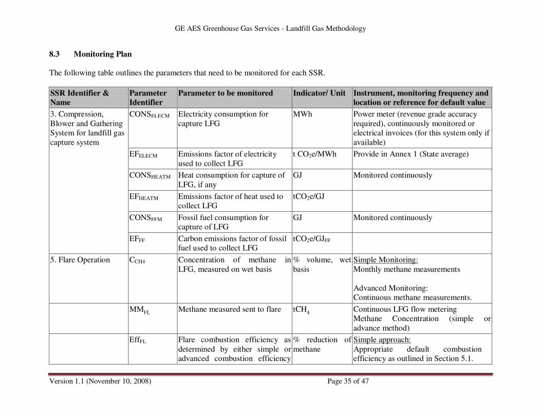
GE AES Greenhouse Gas Services - Landfill Gas Methodology
Version 1.1 (November 10, 2008) Page 35 of 47
8.3 Monitoring Plan
The following table outlines the parameters that need to be monitored for each SSR.
SSR Identifier &
Name
Parameter
Identifier
Parameter to be monitored Indicator/ Unit Instrument, monitoring frequency and
location or reference for default value
CONSELECM Electricity consumption for
capture LFG
MWh Power meter (revenue grade accuracy
required), continuously monitored or
electrical invoices (for this system only if
available)
EFELECM Emissions factor of electricity
used to collect LFG
t CO2e/MWh Provide in Annex 1 (State average)
CONSHEATM Heat consumption for capture of
LFG, if any
GJ Monitored continuously
EFHEATM Emissions factor of heat used to
collect LFG
tCO2e/GJ
CONSFFM Fossil fuel consumption for
capture of LFG
GJ Monitored continuously
3. Compression,
Blower and Gathering
System for landfill gas
capture system
EFFF Carbon emissions factor of fossil
fuel used to collect LFG
tCO2e/GJFF
5. Flare Operation CCH4 Concentration of methane in
LFG, measured on wet basis
% volume, wet
basis
Simple Monitoring:
Monthly methane measurements
Advanced Monitoring:
Continuous methane measurements.
MMFL
Methane measured sent to flare tCH4 Continuous LFG flow metering
Methane Concentration (simple or
advance method)
EffFL Flare combustion efficiency as
determined by either simple or
advanced combustion efficiency
% reduction of
methane
Simple approach:
Appropriate default combustion
efficiency as outlined in Section 5.1.

GE AES Greenhouse Gas Services - Landfill Gas Methodology
Version 1.1 (November 10, 2008) Page 36 of 47
SSR Identifier &
Name
Parameter
Identifier
Parameter to be monitored Indicator/ Unit Instrument, monitoring frequency and
location or reference for default value
methods
Advanced approach:
· Initial and annual performance tests
according to approved
measurement methods, and conduct
continuous monitoring activities to
demonstrate ongoing combustion
efficiency.
· Conduct simultaneous testing of
methane concentration at the inlet
and outlet of the combustion device
annually. Through concurrent
testing of inlet and outlet
concentrations, overall methane
combustion efficiency can be
determined. After an eligible
project determines combustion
efficiency, it shall continuously
monitor outlet methane
concentration, or some other
operational parameter, to ensure
that the combustion device is
operating in a manner similar to
that when the methane testing was
conducted.
· To measure the amount of methane
entering the combustion device,
eligible projects can use the
monitoring methods outlined in
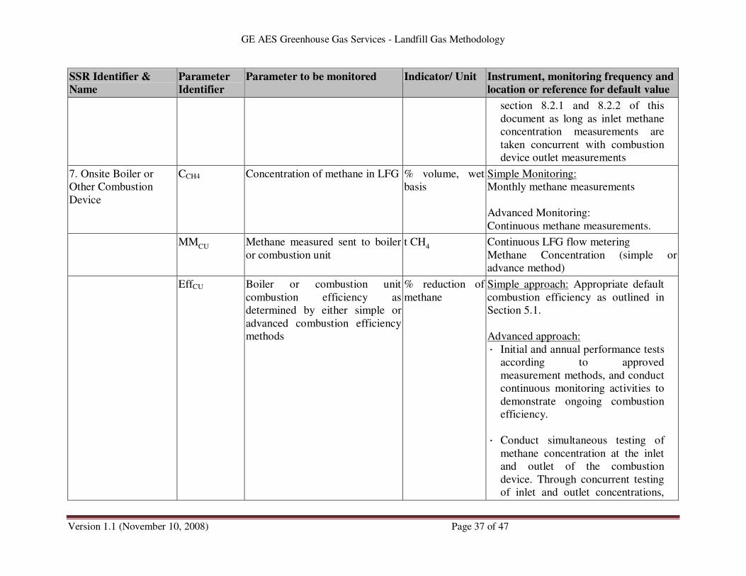
GE AES Greenhouse Gas Services - Landfill Gas Methodology
Version 1.1 (November 10, 2008) Page 37 of 47
SSR Identifier &
Name
Parameter
Identifier
Parameter to be monitored Indicator/ Unit Instrument, monitoring frequency and
location or reference for default value
section 8.2.1 and 8.2.2 of this
document as long as inlet methane
concentration measurements are
taken concurrent with combustion
device outlet measurements
7. Onsite Boiler or
Other Combustion
Device
CCH4 Concentration of methane in LFG % volume, wet
basis
Simple Monitoring:
Monthly methane measurements
Advanced Monitoring:
Continuous methane measurements.
MMCU
Methane measured sent to boiler
or combustion unit
t CH4 Continuous LFG flow metering
Methane Concentration (simple or
advance method)
EffCU Boiler or combustion unit
combustion efficiency as
determined by either simple or
advanced combustion efficiency
methods
% reduction of
methane
Simple approach: Appropriate default
combustion efficiency as outlined in
Section 5.1.
Advanced approach:
· Initial and annual performance tests
according to approved
measurement methods, and conduct
continuous monitoring activities to
demonstrate ongoing combustion
efficiency.
· Conduct simultaneous testing of
methane concentration at the inlet
and outlet of the combustion
device. Through concurrent testing
of inlet and outlet concentrations,

GE AES Greenhouse Gas Services - Landfill Gas Methodology
Version 1.1 (November 10, 2008) Page 38 of 47
SSR Identifier &
Name
Parameter
Identifier
Parameter to be monitored Indicator/ Unit Instrument, monitoring frequency and
location or reference for default value
overall methane combustion
efficiency can be determined. After
an eligible project determines
combustion efficiency, it shall
continuously monitor outlet
methane concentration, or some
other operational parameter, to
ensure that the combustion device
is operating in a manner similar to
that when the methane testing was
conducted.
· To measure the amount of methane
entering the combustion device,
eligible projects can use the
monitoring methods outlined in
section 8.2.1 and 8.2.2 of this
document as long as inlet methane
concentration measurements are
taken concurrent with combustion
device outlet measurements
CCH4 Concentration of methane in LFG % volume (wet
Basis)
Simple Monitoring:
Monthly methane measurements
Advanced Monitoring:
Continuous methane measurements.
8. Onsite Engine,
turbine or other
electrical generating
unit
MMEGU
Methane measured sent to
electrical generation unit
t CH4 Continuous LFG flow metering
Methane Concentration (simple or
advance method)
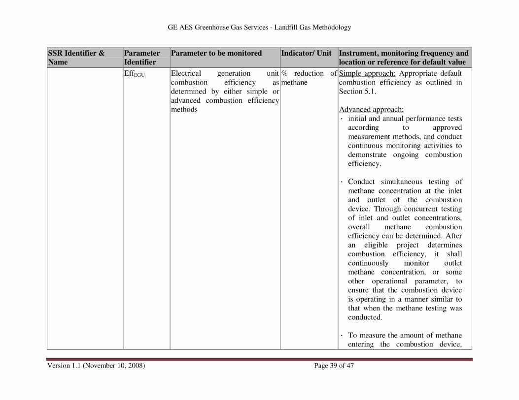
GE AES Greenhouse Gas Services - Landfill Gas Methodology
Version 1.1 (November 10, 2008) Page 39 of 47
SSR Identifier &
Name
Parameter
Identifier
Parameter to be monitored Indicator/ Unit Instrument, monitoring frequency and
location or reference for default value
EffEGU Electrical generation unit
combustion efficiency as
determined by either simple or
advanced combustion efficiency
methods
% reduction of
methane
Simple approach: Appropriate default
combustion efficiency as outlined in
Section 5.1.
Advanced approach:
· initial and annual performance tests
according to approved
measurement methods, and conduct
continuous monitoring activities to
demonstrate ongoing combustion
efficiency.
· Conduct simultaneous testing of
methane concentration at the inlet
and outlet of the combustion
device. Through concurrent testing
of inlet and outlet concentrations,
overall methane combustion
efficiency can be determined. After
an eligible project determines
combustion efficiency, it shall
continuously monitor outlet
methane concentration, or some
other operational parameter, to
ensure that the combustion device
is operating in a manner similar to
that when the methane testing was
conducted.
· To measure the amount of methane
entering the combustion device,
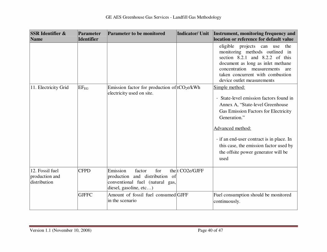
GE AES Greenhouse Gas Services - Landfill Gas Methodology
Version 1.1 (November 10, 2008) Page 40 of 47
SSR Identifier &
Name
Parameter
Identifier
Parameter to be monitored Indicator/ Unit Instrument, monitoring frequency and
location or reference for default value
eligible projects can use the
monitoring methods outlined in
section 8.2.1 and 8.2.2 of this
document as long as inlet methane
concentration measurements are
taken concurrent with combustion
device outlet measurements
11. Electricity Grid EFEG Emission factor for production of
electricity used on site.
tCO2e/kWh Simple method:
· State-level emission factors found in
Annex A, “State-level Greenhouse
Gas Emission Factors for Electricity
Generation.”
Advanced method:
· if an end-user contract is in place. In
this case, the emission factor used by
the offsite power generator will be
used
12. Fossil fuel
production and
distribution
CFPD Emission factor for the
production and distribution of
conventional fuel (natural gas,
diesel, gasoline, etc…)
t CO2e/GJFF
GJFFC Amount of fossil fuel consumed
in the scenario
GJFF Fuel consumption should be monitored
continuously.
GE AES Greenhouse Gas Services - Landfill Gas Methodology
Version 1.1 (November 10, 2008) Page 41 of 47
9 QA/QC and Data Management
Data sets collected from the monitoring system during ongoing project activities must be
retrievable as unmodified results. They may be summarized in a fashion that is suitable for
accounting purposes, but the data sets shall be preserved so that emission reductions can be
verified by a third party. (Refer to monitoring procedures in Section 8).
9.1 Recordkeeping procedures
For purposes of independent verification and historical documentation, eligible projects shall be
required to keep all information outlined in this methodology for various periods. The length of
time a project is required to keep records depends on the type of information.
The following type of information shall be kept accessible for the entire period of time that the
landfill is providing GHG credits:
• Relevant sections of the landfill operating permits (solid waste and air)
• Collection and control device information (installation dates, equipment list, etc)
• LFG flow meter information (model number, serial number, manufacturer’s calibration
procedures)
• Methane monitor information (model number, serial number, manufacturer’s/EPA
calibration procedures)
• Control device monitor information (model number, serial number, manufacturer’s/EPA
calibration procedures)
The following information shall be kept assessable for a period of 5-years after the information is
generated:
• LFG flow data
• LFG flow meter maintenance and inspection data
• Methane monitoring data
• Methane monitor calibration data
• Control device monitoring information
• Control device monitor calibration data
• CO2e hourly calculations
• CO2e daily, monthly, and annual tonnage calculations
• Initial and annual verification records and audit results
Eligible projects may keep these records in electronic and/or hard copy form. However, all
information shall be readily available for verification.
Simple Methane Flow Rate
For the simple methane flow rate method, the following records must be kept in order to
demonstrate valid methane flow rate calculations:
GE AES Greenhouse Gas Services - Landfill Gas Methodology
Version 1.1 (November 10, 2008) Page 42 of 47
• LFG flow meter type, model and serial number
• Date, time, and results of LFG flow meter maintenance and inspection activites
• Date, time, and location of methane measurement
• Methane content of LFG (% by volume) for each measurement
• Methane measurement instrument type and serial number
• Date, time, and results of instrument calibration
• Corrective measures taken if instrument does not meet performance specifications
• Hourly calculations of methane flow rate. Each hour shall have one associated methane
flow rate value.
Advanced Methane Flow Rate
For the advanced methane flow rate method, the following records must be kept in order to
demonstrate valid methane flow rate calculations:
• LFG flow meter type, model and serial number
• Date, time, and results of LFG flow meter maintenance and inspection activities
• Date and time of methane measurement
• Average methane content of LFG (% by volume) for each hour of operation
• Location of methane measurement instrument
• Methane measurement instrument type and serial number
• Summary of methane measurement methods and QA/QC procedures
• Date, time, and results of instrument calibration
• Corrective measures taken if instrument does not meet performance specifications
• Hourly calculations of methane flow rate. Each hour shall have one associated methane
flow rate value.
Simple Combustion Efficiency
For the simple method of determining combustion efficiency, the following records must be kept
in order to validate combustion device operation and apply the default combustion efficiency:
• Type of combustion device and model number if applicable
• Type and location of monitoring parameter and monitoring method
• Date, time, and status of each control device monitoring parameter
• Applied combustion efficiency for each hour
• Results of initial and periodic inspection of monitoring device
Advanced Combustion Efficiency
For the advanced method of determining combustion efficiency, the following records must be
kept in order to validate combustion device operation and demonstrate that site-specific
combustion efficiency can be used to quantify GHG credits:
GE AES Greenhouse Gas Services - Landfill Gas Methodology
Version 1.1 (November 10, 2008) Page 43 of 47
• Type of combustion device and model number if applicable
• Type and location of monitoring parameter and monitoring method
• Date, time, and status of each control device monitoring parameter
• Results of combustion device efficiency testing and calculations of applicable
combustion efficiency.
• Operating parameter value set during previous combustion efficiency testing and hourly
average operating parameter value
• Applied combustion efficiency for each hour
• Results of initial and periodic inspection of monitoring device
10 Emission Reduction Quantification
10.1 Methane Destruction Projects
When a project developer quantifies and request certification of the GHG credits associated with
methane destruction only, then a value of 0 can be assigned to the baseline and the emission
reduction are quantify using the following approach.
Eligible projects will need to determine methane flow and combustion efficiency per the
guidance in Sections 8.1 and 8.2. Based on these data, hourly GHG credits for the eligible
projects can be quantified. Overall, the quantification of GHG credits involves the calculation of
eligible methane delivered to a control device, determination of the destruction efficiency of the
methane control device, conversion of methane destruction to CO2e, and reduction of GHG
credits based on energy needed to collect and transport the methane to the control device. The
following equation shall be used to calculate the GHG credits for each hour of operation:
ERy = ΣMMi * GWP – ΣSSRA where,
ERy metric tonnes of eligible GHG credits
ΣMMi cumulative mass flow rate of methane to the combustion device or injected into
natural gas pipeline (tonnes) (can be based on either the simple or advanced
method under section 8.1.1 or 8.2.1)
ΣSSRA summation of all applicable emissions from SSR’s as calculated per Section 7.1
for the time period associated with the cumulative methane mass flow rate used
in this equation
GWP global warming potential of methane (21)

GE AES Greenhouse Gas Services - Landfill Gas Methodology
Version 1.1 (November 10, 2008) Page 44 of 47
10.2 Displacement Projects Electrical
GHG reductions attributable to displaced grid electricity consumption are addressed in this
methodology but require the GHGS methodology titled Quantification Methodology for
Displacement Projects.
10.3 Displacement Projects Thermal
GHG reductions attributable to displaced thermal energy consumption are addressed in this
methodology but require the GHGS methodology titled Quantification Methodology for
Displacement Projects.
11 Documentation and Reporting
Initial Reporting Requirements
The project developer will provide an initial Project Build Document (PBD) for the specific
project based on the PBD template provided by GHGS. The document is intended to serve as
guidance for the project developers and ensures consistency and transparency between the
various projects proposed and submitted to GGS. It is the responsibility of the project developer
to ensure that all requirements of the LFG Methodology are addressed when drafting the PBD.
This PBD document template contains guidance regarding the type of information that must be
provided by the project developer to provide GGS with a complete understanding of the
proposed GHG project. The PBD outline addresses the various elements of the CMM
Methodology that are required for GGS to document project eligibility, size, and scope. The
project developer should read the guidance provided carefully and complete the PBD
accordingly. The structure of the PBD includes the following items:
• Executive Summary
• Project Description
• Eligibility
• Application of the LFG Methodology
• Estimation of GHG Emissions by Sources
• Quantification of Project Greenhouse Gas Reductions
• Monitoring
• Recordkeeping
• Reporting
• References
• Project Flow Diagrams
Semi-Annual Reporting Requirements
The project developer will provide a semi-annual project status report that includes the following
items:
• Executive summary of project status and signed statement certifying that the collection
and control of the identified landfill gas stream is the result of voluntary action and not

GE AES Greenhouse Gas Services - Landfill Gas Methodology
Version 1.1 (November 10, 2008) Page 45 of 47
required by Federal, State, or Local requirements or consent order and that the project
is in compliance with all applicable Federal, State, and Local ordinances.
• Documentation of any changes or modifications to the project infrastructure or
operation.
• Summary of project eligibility status including: expected dates for compliance with
applicable collection and control requirement of the Landfill NSPS or other applicable
regulations; current NMOC emission rate calculated according to 40 CFR
60.757(b)(1)(ii) for projects at landfills not subject to the collection and control
requirements of the Landfill NSPS or other applicable regulations; and documentation
of changes to any items related to demonstrating project eligibility that were provided
in the initial PBD.
• Results of all verification activities including verification report, identified corrective
actions, and documentation of resolution of corrective actions.
• Monthly and semi-annual summaries of GHG emissions and emission reductions
generated by project based on the LFG Quantification Spreadsheet provided by GHGS.
The project developer must provide the completed spreadsheet.
• Summary of all monitor calibration activities and any associated corrective actions.
• Estimated annual GHG credit generation for subsequent 5-year period, or until
expected project termination date, based on LFG Quantification Spreadsheet provided
by GHGS.

GE AES Greenhouse Gas Services - Landfill Gas Methodology
Version 1.1 (November 10, 2008) Page 46 of 47
ANNEX A – State-level Greenhouse Gas Emission Factors for Electricity Generation13
State metric ton CO2e/MWh
Alabama ................. 0.611
Alaska ................... 0.563
Arizona .................. 0.461
Arkansas ................. 0.594
California ................ 0.138
Colorado ................. 0.929
Connecticut .............. 0.515
Delaware ................. 0.842
Florida ................... 0.650
Georgia .................. 0.644
Hawaii ................... 0.824
Idaho .................... 0.000
Illinois ................... 0.534
Indiana .................. 0.968
Iowa ..................... 0.899
Kansas .................. 0.790
Kentucky ................. 0.901
Louisiana ................ 0.603
Maine .................... 0.408
Maryland* ................ 0.613
Massachusetts ............ 0.561
Michigan ................. 0.790
Minnesota ................ 0.720
Mississippi ............... 0.599
Missouri ................. 0.862
Montana ................. 0.586
Nebraska ................ 0.638
Nevada .................. 0.755
New Hampshire ........... 0.338
New Jersey .............. 0.257
New Mexico .............. 0.952
New York ................ 0.361
North Carolina ............ 0.564
North Dakota ............. 0.993
Ohio ..................... 0.823
Oklahoma ................ 0.802
Oregon .................. 0.080
13
Energy Information Administration. 2001. Updated State-level Greenhouse Gas Emission Factors for
Electricity Generation.

GE AES Greenhouse Gas Services - Landfill Gas Methodology
Version 1.1 (November 10, 2008) Page 47 of 47
State metric ton CO2e/MWh
Pennsylvania ............. 0.554
Rhode Island ............. 0.418
South Carolina ............ 0.370
South Dakota ............. 0.325
Tennessee ............... 0.565
Texas .................... 0.702
Utah ..................... 0.880
Vermont ................. 0.008
Virginia .................. 0.493
Washington .............. 0.083
West Virginia ............. 0.895
Wisconsin ............... 0.813
Wyoming ................ 0.995
*Includes the District of Columbia