gc3 series basic gripper parts list - imi precision · 11/12/98 2 gc3 series flange gripper parts...
TRANSCRIPT

11/12/98 1Our policy is one of continuous research and development. We therefore reservethe right to amend, without notice, the specifications given in this document.
GC3 Series Basic Gripper Parts list
218
2
8
40611
1
21
9
2
218
6
16
201
220
3
7
219
13
13
15215
400
10
200
4 5
402 403 404
3
400
4 5
402 403 404
Refer to your specific head type on pages E-1 to E-3 to determine the proper part numbers for these items.Match detail numbers with last
three digits of part numbers
Detail Part Identification Part Number
1 . . . . . .Base . . . . . . . . . . . . . . . . . . . . . . . . . . . . . .GC3A-0012 . . . . . .Side Plate (2) . . . . . . . . . . . . . . . . . . . . . . .GC3A-0023 . . . . . .Arm . . . . . . . . . . . . . . . . . . . . . . . . . . . . .*GC3A-0036 . . . . . .Rod End . . . . . . . . . . . . . . . . . . . . . . . . . . .GC3A-0067 . . . . . .Pivot Shaft Body Spacer . . . . . . . . . . . . . . .GC3A-0078 . . . . . .Guide Block (2) . . . . . . . . . . . . . . . . . . . . . .GC3A-0089 . . . . . .Bushing (2) . . . . . . . . . . . . . . . . . . . . . . . . .GC3A-00910 . . . . .Roller (2) . . . . . . . . . . . . . . . . . . . . . . . . . . .GC3A-01011 . . . . .Dowel Pin . . . . . . . . . . . . . . . . . . . . . . . . . .GC3A-01113 . . . . .Slot Cover (2) . . . . . . . . . . . . . . . . . . . . . . .GC3A-01315 . . . . .Weld Cover . . . . . . . . . . . . . . . . . . . . . . . . .GC3A-01516 . . . . .Swivel Adapter . . . . . . . . . . . . . . . . . . . . .**GC3A-01621 . . . . .Swivel Spacer . . . . . . . . . . . . . . . . . . . . . .**GC3A-021200 . . . .Cylinder G-1/8 (mag. piston) . . . . . . . . . . . .GC3A-200201 . . . .Cylinder 1/8 NPT(mag. piston) . . . . . . . . . . .GC3A-201215 . . . .M5x0.8x12mm LG Flat Head Screw (2) . . . .01A02028218 . . . .M4x0.7x12mm SH Cap Screw (4) . . . . . . . .01A01998219 . . . .M4x0.7x20mm SH Cap Screw (2) . . . . . . . .01A01586220 . . . .M4x0.7x60mm LG SH Cap Screw (4) . . . .**01A02030402 . . . .Cover Bumper . . . . . . . . . . . . . . . . . . . . . .*GC3A-402
*Refer to Head Type Parts Lists for variations**Refer to Mount Options for variations

11/12/98 2
GC3 Series Flange Gripper Parts List
15
217
222
200 201 220
3
730
7
28
19218
400
218
2
10
8
11
6 16 21
9
13
225
31
20
29
DOUBLE TIP OPTION
Match detail numbers with lastthree digits of part numbers
Detail Part Identification Part Number
1 . . . . .Base . . . . . . . . . . . . . . . . . . . . . . . . . . . . . .GC3B-0012 . . . . .Side Plate (2) . . . . . . . . . . . . . . . . . . . . . . .GC3B-0023 . . . . .Arm . . . . . . . . . . . . . . . . . . . . . . . . . . . . .*GC3B-0036 . . . . .Rod End . . . . . . . . . . . . . . . . . . . . . . . . . . .GC3A-0067 . . . . .Pivot Shaft Body Spacer . . . . . . . . . . . . . . .GC3B-0078 . . . . .Guide Block (2) . . . . . . . . . . . . . . . . . . . . . .GC3A-0089 . . . . .Bushing (2) . . . . . . . . . . . . . . . . . . . . . . . . .GC3A-00910 . . . . .Roller (2) . . . . . . . . . . . . . . . . . . . . . . . . . . .GC3A-01011 . . . . .Dowel Pin . . . . . . . . . . . . . . . . . . . . . . . . . .GC3A-01113 . . . . .Slot Cover (2) . . . . . . . . . . . . . . . . . . . . . . .GC3A-01315 . . . . .Weld Cover (Single Tip) . . . . . . . . . . . . . . . .GC3B-01516 . . . . .Swivel Adapter . . . . . . . . . . . . . . . . . . . . .**GC3A-01619 . . . . .Single Tip . . . . . . . . . . . . . . . . . . . . . . . . . .GC3B-01920 . . . . .Double Tip . . . . . . . . . . . . . . . . . . . . . . . . . .GC3B-02021 . . . . .Swivel Spacer . . . . . . . . . . . . . . . . . . . . . .**GC3A-02128 . . . . .Side Plate . . . . . . . . . . . . . . . . . . . . . . . . . .GC3B-02829 . . . . .Weld Cover (Double Tip) . . . . . . . . . . . . . . .GC3B-209200 . . . .Cylinder G-1/8 (mag. piston) . . . . . . . . . . . .GC3A-200201 . . . .Cylinder 1/8 NPT(mag. piston) . . . . . . . . . . .GC3A-201
Detail Part Identification Part Number
217 . . . .M4x0.7x10mm LH Cap Screw (2 . . . . . . . . .01A02031218 . . . .M4x0.7x12mm SH Cap Screw (4) . . . . . . . .01A01998220 . . . .M4x0.7x60mm LG SH Cap Screw (4) . . . .**01A02030222 . . . .M6x1.0x35mm Hex Bolt . . . . . . . . . . . . . . .**01A02048400 . . . .Cover . . . . . . . . . . . . . . . . . . . . . . . . . . . . .GC3B-400
*Refer to basic gripper exploded view on page D-1**Refer to Mount Options for variations

11/12/98 3Our policy is one of continuous research and development. We therefore reservethe right to amend, without notice, the specifications given in this document.
GC3 Series Head Type Options & Parts Lists
Head Type A1 Parts List
Detail Part Identification Part Number
3 . . . .Arm (2) . . . . . . . . . . . . . . . . . . .GC3A-003400 . . .22-Degree Cover Bumper (2) . . .GC3A-400
Spare Part KitIncludes all of the above . . . . . . .GC3A-A1(see Note A)
HEAD TYPE OPTION: A1WEIGHT: 1.100 LBS [.499 KG]
22.5˚ REF.
45˚4.50 [114.3]
400
3
HEAD TYPE OPTION: A2WEIGHT: 1.095 LBS [.497 KG]
45˚ REF.
90˚5.04 [127.9]
3
402
6
R
HEAD TYPE OPTION: A3WEIGHT: 1.085 LBS [.492 KG]
TYP..47 [12.0]5.53 [140.5] 1 0˚
80˚ EF.
3
403
Dimensions shown are for reference only. Engineered layout drawings areavailable. Contact your ISI Norgren representative for additional information.
NOTE A: When changing from a type A head to another type A head (e.g., A1 to A3) order the cover bumpers only. Ifchanging to a different head type (e.g., A1 to D1) order the spare parts kit for the new head type.
NOTE B: Weights do not include the tips, tip inserts, or spacers.
Head Type A2 Parts List
Detail Part Identification Part Number
3 . . . .Arm (2) . . . . . . . . . . . . . . . . . . .GC3A-003402 . . .45-Degree Cover Bumper (2) . . .GC3A-402
Spare Part KitIncludes all of the above . . . . . . .GC3A-A2(see Note A)
Head Type A3 Parts List
Detail Part Identification Part Number
3 . . . .Arm (2) . . . . . . . . . . . . . . . . . . .GC3A-003403 . . .80-Degree Cover Bumper (2) . . .GC3A-403
Spare Part KitIncludes all of the above . . . . . . .GC3A-A3(see Note A)

11/12/98 4Our policy is one of continuous research and development. We therefore reservethe right to amend, without notice, the specifications given in this document.
Head Type Option D1 requires two different cover bumpers.Refer to the D1 parts list below for part numbers.
GC3 Series Head Type Options & Parts Lists
M4x0.7x12mm LG. S.H.C.S.TORQUE TO 45 IN-LBS [5.1 N-m]
WEIGHT: 1.090 LBS [.494 KG]HEAD TYPE OPTION: D1
TYP. (4)
TORQUE TO 35 IN-LBS [4 N-m]M4x0.7x20mm LG. S.H.C.S.
(PIVOT POINT REF.)TYP. (2)
80˚
22.5˚
5.02 [127.6]
3
400
5
403
.47 [12.0]
3.61 [91.7]
.63 [16.0]
50˚
M4x0.7x12mm LG. S.H.C.S.TORQUE TO 45 IN-LBS [5.1 N-m]TYP. (8)
HEAD TYPE OPTION: F1WEIGHT: 1.225 LBS [.558 KG]
400
3
Dimensions shown are for reference only. Engineered layout drawings areavailable. Contact your ISI Norgren representative for additional information.
NOTE A: When changing from a type A head to another type A head (e.g., A1 to A3) order the cover bumpers only. Ifchanging to a different head type (e.g., D1 to A1) order the spare parts kit for the new head type.
NOTE B: Weights do not include the tips, tip inserts, or spacers.
Head Type D1 Parts List
Detail Part Identification Part Number
3 . . . .Arm (1) . . . . . . . . . . . . . . . . . . .GC3A-0035 . . . .Arm (1) . . . . . . . . . . . . . . . . . . .GC3A-005
404 . . .0-Degree Cover Bumper (1) . . . .GC3A-404403 . . .80-Degree Cover Bumper (1) . . .GC3A-403
Spare Part KitIncludes all of the above . . . . . . .GC3A-D1(see Note A)
Head Type F1 Parts List
Detail Part Identification Part Number
3 . . . .Arm (2) . . . . . . . . . . . . . . . . . . .GC3B-003400 . . .Cover (2) . . . . . . . . . . . . . . . . . .GC3B-400
Spare Part KitIncludes all of the above . . . . . . .GC3A-F1(see Note A)

11/12/98 5Our policy is one of continuous research and development. We therefore reservethe right to amend, without notice, the specifications given in this document.
GC3 Series Head Type Options & Parts Lists
Head Type Options U1. U2, U3 and L1, L2, L3 each requires two differentcover bumpers. Refer to the part listings below for part numbers.
WEIGHT: 1.190 LBS [.476 KG]
HEAD TYPE OPTION: U2 or L2
4.25 [108.0]
45˚
3
402
4
404
214
HEAD TYPE OPTION: U3 or L3WEIGHT: 1.050 LBS [.476 KG]
4.50 [114.3]
80˚
3
403
4
404
214
WEIGHT: 1.190 LBS [.476 KG]
HEAD TYPE OPTION: U1 or L1
22.5˚
3.99 [101.3]
400
3
4
404
214
Dimensions shown are for reference only. Engineered layout drawings areavailable. Contact your ISI Norgren representative for additional information.
NOTE A: When changing from a type U or L head to another type U or L head (e.g., U1 to L3) order the cover bumpersonly. If changing to a different head type (e.g., U1 to A1) order the spare parts kit for the new head type.
NOTE B: Weights do not include the tips, tip inserts, or spacers.
Head Type U1 or L1 Parts List
Detail Part Identification Part Number
3 . . . .Arm (1) . . . . . . . . . . . . . . . . . . .GC3A-0034 . . . .Fixed Arm (1) . . . . . . . . . . . . . . .GC3A-004
214 . . .Dowel . . . . . . . . . . . . . . . . . . . . . . . . .214400 . . .22-Degree Cover Bumper (1) . . .GC3A-400404 . . .0-Degree Cover Bumper (1) . . . .GC3A-404
Spare Part KitIncludes all of the above . . . . . .GC3A-UL1(see Note A)
Head Type U2 or L2 Parts List
Detail Part Identification Part Number
3 . . . .Arm (1) . . . . . . . . . . . . . . . . . . .GC3A-0034 . . . .Fixed Arm (1) . . . . . . . . . . . . . . .GC3A-004
214 . . .Dowel . . . . . . . . . . . . . . . . . . . . . . . . .214402 . . .45-Degree Cover Bumper (1) . . .GC3A-402404 . . .0-Degree Cover Bumper (1) . . . .GC3A-404
Spare Part KitIncludes all of the above . . . . . .GC3A-UL2(see Note A)
Head Type U3 or L3 Parts List
Detail Part Identification Part Number
3 . . . .Arm (1) . . . . . . . . . . . . . . . . . . .GC3A-0034 . . . .Fixed Arm (1) . . . . . . . . . . . . . . .GC3A-004
214 . . .Dowel . . . . . . . . . . . . . . . . . . . . . . . . .214403 . . .80-Degree Cover Bumper (1) . . .GC3A-403404 . . .0-Degree Cover Bumper (1) . . . .GC3A-404
Spare Part KitIncludes all of the above . . . . . .GC3A-UL3(see Note A)

NOTE:
1. Using Tip Spacers fixes the gap between the upper and lower Tip Inserts. Refer to the chart above for recommendations.2. Removing the spacers makes the Tip Inserts fully adjustable.3. Chisel tips are not adjustable. The upper jaw will include a convex insert or inserts if applied to Tip Option B.
3/15/99 6
GC3 Series Tip Option Part Lists
36
223 35
22
19
226
23 24
Single Tip
Single Tip Option A Parts List
Detail Part Identification Part Number
19 . . . .Single Tip (2) . . . . . . . . . . . . . . .GC3A-019223 . . .M6x1.0x20mm Hex Bolt (2) . . . .01A02047226 . . .M6x1.0 Lock Nut (2) . . . . . . . . . .02A01316
Spare Part KitIncludes all of the above . . . . . . .GC3A-TA
Double Tip Option A Parts List
Detail Part Identification Part Number
20 . . . .Double Tip (2) . . . . . . . . . . . . . .GC3A-020223 . . .M6x1.0x20mm Hex Bolt (2) . . . .01A02047226 . . .M6x1.0 Lock Nut (2) . . . . . . . . . .02A01316
Spare Part KitIncludes all of the above . . . . . . .GC3A-TB
20
39
223
226
Double Tip
27
26
25
217
S.C.H.S.Chisel Tip
Note: Reference all threefigures on this page whenlocating and identifyingspacer and insert options.
Tip Spacer Options
Option 1:Black
Recommended for panel or partthicknesses of 0.00mm - 1.25mm
Recommended for panel or partthicknesses of 1.25mm - 2.50mm
Recommended for panel or partthicknesses of 2.50mm - 3.75mm
Option 2:Silver
Option 3:Gold
Spacers forTip Options
A and B
Spacers forTip Options
C and D
SpacerLocations
Regular Chisel
Single and Double Chisel Tip Spacers Parts List
Detail Part Identification Part Number Single Double Tip Qty. Tip Qty.
22 ............Option 1 Spacer (black) . . . . . . GC3A-022 . . . . . . . . . 2 . . . . . . . . . 423 ............Option 2 Spacer (silver) . . . . . . GC3A-023 . . . . . . . . . 2 . . . . . . . . . 424.............Option 3 Spacer (gold) . . . . . . GC3A-024 . . . . . . . . . 2 . . . . . . . . . 4
25 ............Option 1 Spacer (black) . . . . . . GC3A-025 . . . . . . . . . 2 . . . . . . . . . 426 ............Option 2 Spacer (silver) . . . . . . GC3A-026 . . . . . . . . . 2 . . . . . . . . . 427.............Option 3 Spacer (gold) . . . . . . GC3A-027 . . . . . . . . . 2 . . . . . . . . . 4217 M6x1.0x25mm Low Head Cap Screw. 01A02031 . . . . . . . . . 1 . . . . . . . . . 2226 ................M6x1.0 Lock Nut . . . . . . . . 02A01316 . . . . . . . . . 2 . . . . . . . . . 4
Note: Option B insert (carbide) is not available with the chisel tip.

11/12/98 7Our policy is one of continuous research and development. We therefore reservethe right to amend, without notice, the specifications given in this document.
GC3 Series Edge Guard Option Part Lists
224
401
228
227 18
229
405
216
Positive Lock Adj. Edge Guard Parts List
Detail Part Identification Part Number
18 . . . .Edge Guard Insert (2) . . . . . . . .GC3A-018401 . . .Edge Guard (2) . . . . . . . . . . . . .GC3A-401224 . . .M5x0.8x6mm Set Screw (2) . . .01A02032227 . . .Prevailing Torque Nut (2) . . . . . .02A01329228 . . .Washer (2) . . . . . . . . . . . . . . . . .04A01217
Spare Part KitIncludes all of the above . . . . . . .GC3A-G1
Spare Part Kit for use with Proximity Sensing Includes one (1) ea. of all the above . . . . .GC3A-PSCE
Adjustable Edge Guard Parts List
Detail Part Identification Part Number
405 . . .Edge Guard (2) . . . . . . . . . . . . .GC3A-405216 . . .M4x0.7x8mm LH Cap Screw (6) 01A01999
Spare Part KitIncludes all of the above . . . . . . .GC3A-G2
Spare Part Kit for use with Proximity Sensing Includes one (1) Edge Guard andthree (3) Low Head Cap screws . . . . . . . .GC3A-PSDF

11/12/98 8Our policy is one of continuous research and development. We therefore reservethe right to amend, without notice, the specifications given in this document.
GC3 Series Mounting Option Part Lists
21
16
17
220
221
14
40
12
225
222
41
220
MT1 Rod Mount Parts List (English)
Detail Part Identification Part Number
12 . . . .Orbital Cap (1) . . . . . . . . . . . . . .GC3A-01214 . . . .Orbital Mount (1) . . . . . . . . . . . .GC3A-01416 . . . .Swivel Adapter . . . . . . . . . . . . . .GC3A-01640 . . . .Orbital Ball (1) . . . . . . . . . . . .P-GLM500-9
220 . . .M4x0.7x60mm SHCS (4) . . . . . .01A02030222 . . .M8x1.25x35mm SHCS (2) . . . . .01A02048225 . . .S8 Serrated Washer (2) . . . . . . .04A01216
Spare Part KitIncludes all of the above . . . . . .GC3A-MT1
MT2 Rod Mount Parts List (Metric)
Detail Part Identification Part Number
12 . . . .Orbital Cap (1) . . . . . . . . . . . . . .GC3A-01214 . . . .Orbital Mount (1) . . . . . . . . . . . .GC3A-01416 . . . .Swivel Adapter . . . . . . . . . . . . . .GC3A-01641 . . . .Orbital Ball (1) . . . . . . . . . . .P-XGLM500-9220 . . .M4x0.7x60mm SHCS (4) . . . . . .01A02030222 . . .M8x1.25x35mm SHCS (2) . . . . .01A02048225 . . .S8 Serrated Washer (2) . . . . . . .04A01216
Spare Part KitIncludes all of the above . . . . . .GC3A-MT2
MT3 Flange Mount Parts List
Detail Part Identification Part Number
16 . . . .Swivel Adapter (1) . . . . . . . . . . .GC3A-01617 . . . .Rear Flange (1) . . . . . . . . . . . . .GC3A-01721 . . . .Swivel Spacer (1) . . . . . . . . . . .GC3A-021
221 . . .M4x0.7x70mm SHCS (4) . . . . . .01A01522
Spare Part KitIncludes all of the above . . . . . .GC3A-MT3
MTX No Mount Option Parts List
Detail Part Identification Part Number
16 . . . .Swivel Adapter (1) . . . . . . . . . . .GC3A-01621 . . . .Swivel Spacer (1) . . . . . . . . . . .GC3A-021
220 . . .M4x0.7x60mm SHCS (4) . . . . . .01A02030
Spare Part KitIncludes all of the above . . . . . .GC3A-MTX

GC Series Mounting Option Part List
10/98 9Our policy is one of continuous research and development. We therefore reservethe right to amend, without notice, the specifications given in this document.
47
42
46
231
230
43
220
MT4 Rod Mount Parts List (English)
Detail Part Identification Part Number
46 . . . .Orbital Cap (1) . . . . . . . . . . . . . .GC3A-04647 . . . .Orbital Mount (1) . . . . . . . . . . . .GC3A-04716 . . . .Swivel Adapter . . . . . . . . . . . . . .GC3A-01642 . . . .Orbital Ball (1) . . . . . . . . . . . .P-GLM700-5
220 . . .M4x0.7x60mm SHCS (4) . . . . . .01A01756230 . . .M10x1.5x50mm SHCS (2) . . . . .01A01609231 . . .S10 Serrated Washer (2) . . . . . .04A01207
Spare Part KitIncludes all of the above . . . . . .GC3A-MT4
MT5 Rod Mount Parts List (Metric)
Detail Part Identification Part Number
46 . . . .Orbital Cap (1) . . . . . . . . . . . . . .GC3A-04647 . . . .Orbital Mount (1) . . . . . . . . . . . .GC3A-04716 . . . .Swivel Adapter . . . . . . . . . . . . . .GC3A-01643 . . . .Orbital Ball (1) . . . . . . . . . . .P-XGLM700-5220 . . .M4x0.7x60mm SHCS (4) . . . . . .01A01756230 . . .M10x1.5x50mm SHCS (2) . . . . .01A01609231 . . .S10 Serrated Washer (2) . . . . . .04A01207
Spare Part KitIncludes all of the above . . . . . .GC3A-MT5

11/12/98 10Our policy is one of continuous research and development. We therefore reservethe right to amend, without notice, the specifications given in this document.
GC3 Series Proximity Sensing Part Lists
2
1
200
201
400
Proximity Sensing Parts List
Detail Part Identification Part Number
1 . . . .Sensor Housing (1) . . . . . . . . . .GC3AS0012 . . . .Target (1) . . . . . . . . . . . . . . . . .GC3AS002
200 . . .Status Controller (1) . . . . . . . .GC4AS200201 . . .M4x0.7x20mm LH Cap Screw . .01A02039400 . . .Sensor Label . . . . . . . . . . . . . .GC3AS400
Sensor AssemblyIncludes all of the above . . . . . . .GC3-PS1
2
1200
201
400
PS2 Proximity Sensing Parts List
Detail Part Identification Part Number
1 . . . .Sensor Housing (1) . . . . . . . . . .GC3AT0012 . . . .Target (1) . . . . . . . . . . . . . . . . .GC3AT002
200 . . .Status Controller (1) . . . . . . . . .GC3AT200201 . . .M4x0.7x20mm LH Cap Screw . .01A02039400 . . .Sensor Label . . . . . . . . . . . . . . .GC3AT400
Sensor AssemblyIncludes all of the above . . . . . . .GC3-PS2
Attention: Make sure wires do not get pinched between the housing and gripperbody when replacing the status controller assembly. Failure to do so may cause permanent damage.
11/12/98 11Our policy is one of continuous research and development. We therefore reservethe right to amend, without notice, the specifications given in this document.
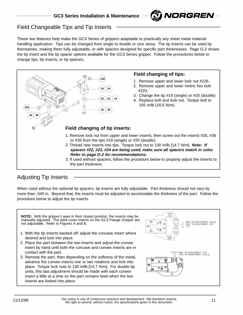
GC3 Series Installation & Maintenance
Field changing of tips:
3936
22335 39
22
19 20
226
23 24
1. Remove upper and lower lock nut #226.2. Remove upper and lower metric hex bolt
#223.3. Change the tip #19 (single) or #20 (double) 4. Replace bolt and lock nut. Torque bolt to
165 in/lb (18.6 N/m).
Field Changeable Tips and Tip Inserts
These two features help make the GC3 Series of grippers adaptable to practically any sheet metal material handling application. Tips can be changed from single to double or vice versa. The tip inserts can be used bythemselves, making them fully adjustable, or with spacers designed for specific part thicknesses. Page G-2 showsthe tip insert and the tip spacer options available for the GC3 Series gripper. Follow the procedures below tochange tips, tip inserts, or tip spacers.
TYP. MIN. TIP ADJUSTMENT: 0.00MAX. TIP ADJUSTMENT: .18 [4.6]
MAX. TIP ADJUSTMENT: .21 [5.3]MIN. TIP ADJUSTMENT: 0.00
When used without the optional tip spacers, tip inserts are fully adjustable. Part thickness should not vary bymore than .040 in. Beyond that, the inserts must be adjusted to accomodate the thickness of the part. Follow theprocedure below to adjust the tip inserts.
Adjusting Tip Inserts
NOTE: With the gripper’s jaws in their closed position, the inserts may bemanually adjusted. The weld cover inserts on the GC3 Flange Gripper arenot adjustable. Refer to Figures A and B.
1. With the tip inserts backed off, adjust the concave insert wheredesired and lock into place.
2. Place the part between the two inserts and adjust the convexinsert by hand until both the concave and convex inserts are incontact with the part.
3. Remove the part, then depending on the softness of the metal,advance the convex inserts one or two rotations and lock intoplace. Torque lock nuts to 130 in/lb [14.7 N/m]. For double tipunits, this last adjustment should be made with each convexinsert a little at a time so the part remains level when the twoinserts are locked into place.
Field changing of tip inserts:
1. Remove lock nut from upper and lower inserts, then screw out the inserts #35, #36or #39 from the tips #19 (single) or #20 (double).
2. Thread new inserts into tips. Torque lock nut to 130 in/lb [14.7 N/m] Note: Ifspacers #22, #23, #24 are being used, make sure all spacers match in color.Refer to page G-2 for recommendations.
3. If used without spacers, follow the procedure below to properly adjust the inserts tothe part thickness.

GC Series
3/15/99 12Our policy is one of continuous research and development. We therefore reservethe right to amend, without notice, the specifications given in this document.
Tip Insert Options
.23 [6.0]
.20 [5.0]
1.18 [30.0] ]
.39 [10.0]
.39 [10.0]
.39 [10.0]
CONCAVE INSERTCONVEX INSERT CARBIDE STEEL INSERT
FLATSFLATS
M6x1.0 THD
.23 [6.0]
.20 [5.0]
1.18 [30.0]
.39 [10.0]
.39 [10.0]
M6x1.0 THD
]
.23 [6.0]
.20 [5.0]
1.18 [30.0]
.39 [10.0]
M6x1.0 THD.
OPTION A OPTION B
Single and Double Tip Insert Parts List
Detail Part I.D. Part No. Single DoubleTip QtyTip Qty
35 . . . . . Option A Insert (convex) . . X3-PT11............1 . . . . . . 2
36 . . . . Option A Insert (concave) . X3-PT12............1 . . . . . . 2
39 . . . . . Option B Insert (carbide) . . X3-PT5 ............2 . . . . . . 4
40 35
41 39
35
36
39
39
Tip Insert Options
Single and Double Flange Tip Insert Parts List
Detail Part I.D. Part No. Single DoubleTip QtyTip Qty
40 . . . . Option A Insert (concave) GC3B-031 ..........1 . . . . . . 2for Flange Weld Guard
35 . . . . . Option A Insert (convex) . . X3-PT11............1 . . . . . . 2
41 . . . . Option B Insert (carbide). GC3B-032 ..........1 . . . . . . 2for Flange Weld Guard
39 . . . . . Option B Insert (carbide) . . X3PT5.............1 . . . . . . 2

11/12/98 13Our policy is one of continuous research and development. We therefore reservethe right to amend, without notice, the specifications given in this document.
GC3 Series Installation & Maintenance
Field changing arms:1. Loosen two (2) flathead screws #215 and
remove weld cover #15.2. Remove the two (2) socket head cap screws
#218, the one (1) socket head cap screw #219,and side plate #2 (side plate shown withoutcover).
3. Remove guide block #8 and slide off arm #3.4. Replace arm and guide block, making sure the
bumper is properly seated, replace side plate,the two (2) #218 socket head cap screws, andthe one (1) #219 socket head cap screw.Torque the #218 screws to 45 in/lb [5.1 N/m]and the #219 screw to 35 in/lb [4 N/m].
Field changing bumpers to changehead type:1. Loosen (no need to remove) the two flathead
screws #215.2. Tip and and remove bumper(s) #402.3. Replace with new bumper (see Note below).4. Retighten 2 flathead screws. Torque to 50 in/lb
(5.5 N/m).
NOTE:1. Head Type Options A1, A2 & A3 each use identical bumpers. Refer to page E-1 for kit information and part callouts.
2. Head Type Option D1 uses a single 22° bumper and a single 80° bumper. Refer to page E-2 for kit information and part callouts.
3. Head Type Options L1, L2, L3, U1, U2, & U3 all use a single 0° bumper combined with an opposing 22°, 45° or 80° arm bumper.
Refer to page E-3 for kit information and part callouts.
218
219
2
8
3 15
215
Field Changeable Arms
Field Changeable Head Types
15
215
400 402
403 404
400 402
403 404

11/12/98 14Our policy is one of continuous research and development. We therefore reservethe right to amend, without notice, the specifications given in this document.
GC3 Series Installation & Maintenance
220
221
6
200
201
406
Replacing the cylinder:1. Loosen the two orbital mount set screws #406.2. Remove four (4) long socket head cap screws #220 or
#221 depending on mount options.3. Pull gripper head and cylinder #200 or #201 apart with
your hands until the rod end #6 is exposed.4. Being careful not to mar the surface, secure the rod
end which is now visible and unthread the cylinder fromthe rod end.
Changing the Cylinder
Lubricating Instructions:1. Use Mobil XTC Premium Lubricating Grease.2. Coat both sides of the middle section of the base #1.3 Coat inner side and slot of side plates #2.4. Coat lower half (both sides) inner surface of slot and pivot
hole of arms #3, #4, or #5, depending on head type.5. Coat all sides of guide blocks, #8.6. Coat I.D. and O.D. of rollers, #10.7. Coat length of dowel pin, #11.
2
8
8
11
1
2
3
10
10
4 5
3 4 5
Lubricating the GC Gripper

GC Series
10/98 15Our policy is one of continuous research and development. We therefore reservethe right to amend, without notice, the specifications given in this document.

GC Series
10/98 16Our policy is one of continuous research and development. We therefore reservethe right to amend, without notice, the specifications given in this document.

1/8/99 1Our policy is one of continuous research and development. We therefore reservethe right to amend, without notice, the specifications given in this document.
GC4 Series Basic Gripper Parts list
218
2
8
40611
1
21
9
2
218
6
16
201
220
3
7
219
13
13
15215
400
10
200
4 5
402 403 404
3
400
4 5
402 403 404
Refer to your specific head type on pages E-1 to E-3 to determine the proper part numbers for these items.
Detail Part Identification Part Number
1 . . . . . .Base . . . . . . . . . . . . . . . . . . . . . . . . . . . . . .GC4A-0012 . . . . . .Side Plate (2) . . . . . . . . . . . . . . . . . . . . . . .GC4A-0023 . . . . . .Arm . . . . . . . . . . . . . . . . . . . . . . . . . . . . .*GC4A-0036 . . . . . .Rod End . . . . . . . . . . . . . . . . . . . . . . . . . . .GC4A-0067 . . . . . .Pivot Shaft Body Spacer . . . . . . . . . . . . . . .GC4A-0078 . . . . . .Guide Block (2) . . . . . . . . . . . . . . . . . . . . . .GC4A-0089 . . . . . .Bushing (2) . . . . . . . . . . . . . . . . . . . . . . . . .GC4A-00910 . . . . .Roller (2) . . . . . . . . . . . . . . . . . . . . . . . . . . .GC4A-01011 . . . . .Dowel Pin . . . . . . . . . . . . . . . . . . . . . . . . . .GC4A-01113 . . . . .Slot Cover (2) . . . . . . . . . . . . . . . . . . . . . . .GC4A-01315 . . . . .Weld Cover . . . . . . . . . . . . . . . . . . . . . . . . .GC4A-01516 . . . . .Swivel Adapter . . . . . . . . . . . . . . . . . . . . .**GC4A-01621 . . . . .Swivel Spacer . . . . . . . . . . . . . . . . . . . . . .**GC4A-021200 . . . .Cylinder G-1/8 (mag. piston) . . . . . . . . . . . .GC4A-200201 . . . .Cylinder 1/8 NPT(mag. piston) . . . . . . . . . . .GC4A-201215 . . . .M5x0.8x12mm LG Flat Head Screw (2) . . . .01A02015218 . . . .M4x0.7x12mm SH Cap Screw (4) . . . . . . . .01A01681219 . . . .M4x0.7x20mm SH Cap Screw (2) . . . . . . . .01A01299220 . . . .M4x0.7x60mm LG SH Cap Screw (4) . . . .**01A01756402 . . . .Cover Bumper . . . . . . . . . . . . . . . . . . . . . .*GC4A-402
*Refer to Head Type Parts Lists for variations**Refer to Mount Options for variations
1/8/99 2Our policy is one of continuous research and development. We therefore reservethe right to amend, without notice, the specifications given in this document.
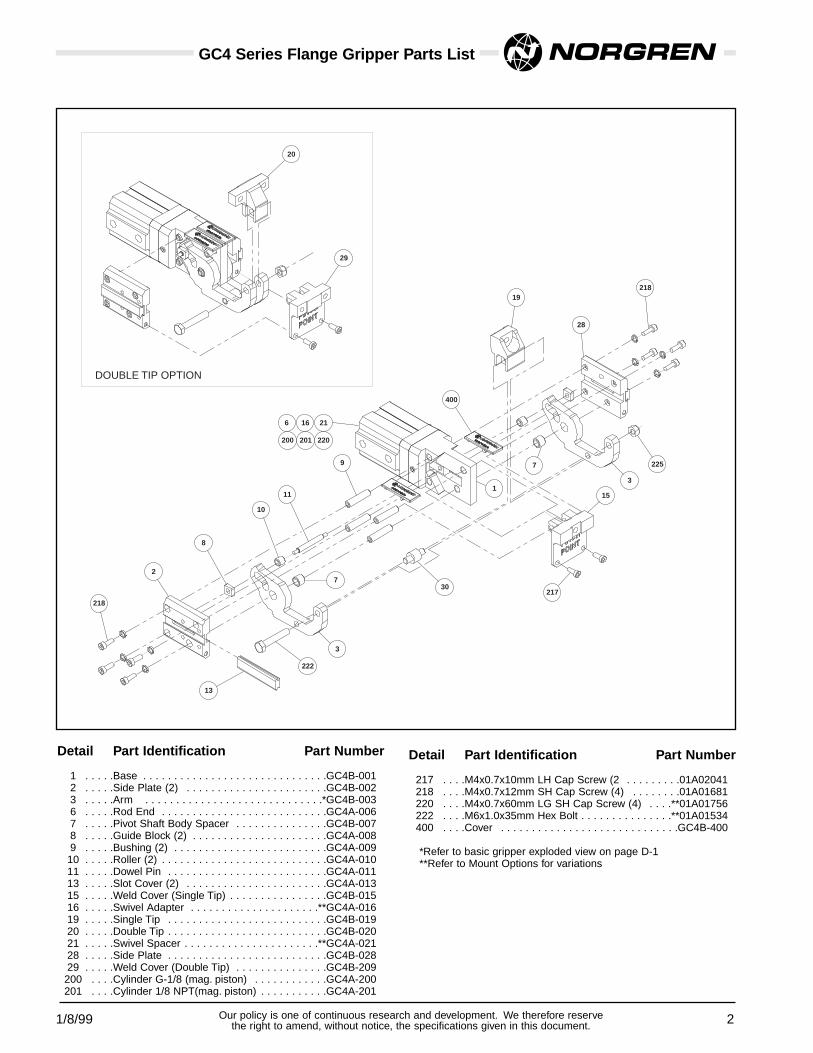
GC4 Series Flange Gripper Parts List
15
217
222
200 201 220
3
730
7
28
19218
400
218
2
10
8
11
6 16 21
9
13
225
31
20
29
DOUBLE TIP OPTION
Detail Part Identification Part Number
1 . . . . .Base . . . . . . . . . . . . . . . . . . . . . . . . . . . . . .GC4B-0012 . . . . .Side Plate (2) . . . . . . . . . . . . . . . . . . . . . . .GC4B-0023 . . . . .Arm . . . . . . . . . . . . . . . . . . . . . . . . . . . . .*GC4B-0036 . . . . .Rod End . . . . . . . . . . . . . . . . . . . . . . . . . . .GC4A-0067 . . . . .Pivot Shaft Body Spacer . . . . . . . . . . . . . . .GC4B-0078 . . . . .Guide Block (2) . . . . . . . . . . . . . . . . . . . . . .GC4A-0089 . . . . .Bushing (2) . . . . . . . . . . . . . . . . . . . . . . . . .GC4A-00910 . . . . .Roller (2) . . . . . . . . . . . . . . . . . . . . . . . . . . .GC4A-01011 . . . . .Dowel Pin . . . . . . . . . . . . . . . . . . . . . . . . . .GC4A-01113 . . . . .Slot Cover (2) . . . . . . . . . . . . . . . . . . . . . . .GC4A-01315 . . . . .Weld Cover (Single Tip) . . . . . . . . . . . . . . . .GC4B-01516 . . . . .Swivel Adapter . . . . . . . . . . . . . . . . . . . . .**GC4A-01619 . . . . .Single Tip . . . . . . . . . . . . . . . . . . . . . . . . . .GC4B-01920 . . . . .Double Tip . . . . . . . . . . . . . . . . . . . . . . . . . .GC4B-02021 . . . . .Swivel Spacer . . . . . . . . . . . . . . . . . . . . . .**GC4A-02128 . . . . .Side Plate . . . . . . . . . . . . . . . . . . . . . . . . . .GC4B-02829 . . . . .Weld Cover (Double Tip) . . . . . . . . . . . . . . .GC4B-209200 . . . .Cylinder G-1/8 (mag. piston) . . . . . . . . . . . .GC4A-200201 . . . .Cylinder 1/8 NPT(mag. piston) . . . . . . . . . . .GC4A-201
Detail Part Identification Part Number
217 . . . .M4x0.7x10mm LH Cap Screw (2 . . . . . . . . .01A02041218 . . . .M4x0.7x12mm SH Cap Screw (4) . . . . . . . .01A01681220 . . . .M4x0.7x60mm LG SH Cap Screw (4) . . . .**01A01756222 . . . .M6x1.0x35mm Hex Bolt . . . . . . . . . . . . . . .**01A01534400 . . . .Cover . . . . . . . . . . . . . . . . . . . . . . . . . . . . .GC4B-400
*Refer to basic gripper exploded view on page D-1**Refer to Mount Options for variations

1/8/99 3Our policy is one of continuous research and development. We therefore reservethe right to amend, without notice, the specifications given in this document.
GC4 Series Head Type Options & Parts Lists
HEAD TYPE OPTION: A1WEIGHT: 2.075 LB [.941KG]
22.5˚ REF.
45˚5.76 [146.4]
400
3
HEAD TYPE OPTION: A 2WEIGHT: 2.065 LB [.937]
45˚ REF.
90˚6.36 [161.6]
3
402
6
R
HEAD TYPE OPTION: A3WEIGHT: 2.055 LB [.932 KG]
6.94 [176.3] 1 0˚
80˚ EF.
3
403
Head Type A1 Parts List
Detail Part Identification Part Number
3 . . . .Arm (2) . . . . . . . . . . . . . . . . . . .GC4A-003400 . . .22-Degree Cover Bumper (2) . . .GC4A-400
Spare Part KitIncludes all of the above . . . . . . .GC4A-A1(see Note A)
Dimensions shown are for reference only. Engineered layout drawings areavailable. Contact your ISI Norgren representative for additional information.
NOTE A: When changing from a type A head to another type A head (e.g., A1 to A3) order the cover bumpers only. Ifchanging to a different head type (e.g., A1 to D1) order the spare parts kit for the new head type.
NOTE B: Weights do not include the tips, tip inserts, or spacers
Head Type A2 Parts List
Detail Part Identification Part Number
3 . . . .Arm (2) . . . . . . . . . . . . . . . . . . .GC4A-003402 . . .45-Degree Cover Bumper (2) . . .GC4A-402
Spare Part KitIncludes all of the above . . . . . . .GC4A-A2(see Note A)
Head Type A3 Parts List
Detail Part Identification Part Number
3 . . . .Arm (2) . . . . . . . . . . . . . . . . . . .GC4A-003403 . . .80-Degree Cover Bumper (2) . . .GC4A-403
Spare Part KitIncludes all of the above . . . . . . .GC4A-A3(see Note A)

1/8/99 4Our policy is one of continuous research and development. We therefore reservethe right to amend, without notice, the specifications given in this document.
M5x0.8x16mm LG. S.H.C.S.TORQUE TO 90 IN-LBS [10 N-m]
WEIGHT: 2.050 LB [.930 KG]HEAD TYPE OPTION: D1
TYP. (4)
TORQUE TO 75 IN-LBS [9 N-m]M5x0.8x25mm LG. S.H.C.S.
(PIVOT POINT REF.)TYP. (2)
80˚
22.5˚
6.35 [161.4]
3
400
5
403
Head Type Option D1 requires two different cover bumpers.Refer to the D1 parts list below for part numbers.
.59 [15.0]
4.39 [111.5]
.72 [18.3]
50˚
M5x0.8x16mm LG. S.H.C.S.TORQUE TO 90 IN-LBS [10 N-m]TYP. (8)
HEAD TYPE OPTION: F1WEIGHT: 1.880 LB [.853 KG]
400
3
GC4 Series Head Type Options & Parts Lists
75 in-lbs [9 N-m]
90 in-lbs [10 N-m]
Dimensions shown are for reference only. Engineered layout drawings areavailable. Contact your ISI Norgren representative for additional information.
NOTE A: When changing from a type A head to another type A head (e.g., A1 to A3) order the cover bumpers only. Ifchanging to a different head type (e.g., D1 to A1) order the spare parts kit for the new head type.
NOTE B: Weights do not include the tips, tip inserts, or spacers
Head Type D1 Parts List
Detail Part Identification Part Number
3 . . . .Arm (1) . . . . . . . . . . . . . . . . . . .GC4A-0035 . . . .Arm (1) . . . . . . . . . . . . . . . . . . .GC4A-005
404 . . .0-Degree Cover Bumper (1) . . . .GC4A-404403 . . .80-Degree Cover Bumper (1) . . .GC4A-403
Spare Part KitIncludes all of the above . . . . . . .GC4A-D1(see Note A)
Head Type F1 Parts List
Detail Part Identification Part Number
3 . . . .Arm (2) . . . . . . . . . . . . . . . . . . .GC4B-003400 . . .Cover (2) . . . . . . . . . . . . . . . . . .GC4B-400
Spare Part KitIncludes all of the above . . . . . . .GC4A-F1(see Note A)

1/8/99 5Our policy is one of continuous research and development. We therefore reservethe right to amend, without notice, the specifications given in this document.
WEIGHT: 2.055 LB [.932 KG]
HEAD TYPE OPTION: U2 or L2
5.42 [137.8]
45˚
3
402
4
404
214
HEAD TYPE OPTION: U3 or L3WEIGHT: 2.050 LB [.930 KG]
5.71 [145.2]
80˚
3
403
4
404
214
WEIGHT: 2.060 LB [.934 KG]
HEAD TYPE OPTION: U1 or L1
22.5˚
5.13 [130.2]
400
3
GC4 Series Head Type Options & Parts Lists
Head Type Options U1. U2, U3 and L1, L2, L3 each requires two differentcover bumpers. Refer to the part listings below for part numbers.
Dimensions shown are for reference only. Engineered layout drawings areavailable. Contact your ISI Norgren representative for additional information.
NOTE A: When changing from a type U or L head to another type U or L head (e.g., U1 to L3) order the cover bumpersonly. If changing to a different head type (e.g., U1 to A1) order the spare parts kit for the new head type.
NOTE B: Weights do not include the tips, tip inserts, or spacers
Head Type U1 or L1 Parts List
Detail Part Identification Part Number
3 . . . .Arm (1) . . . . . . . . . . . . . . . . . . .GC4A-0034 . . . .Fixed Arm (1) . . . . . . . . . . . . . . .GC4A-004
214 . . .Dowel . . . . . . . . . . . . . . . . . . . . .06A01429400 . . .22-Degree Cover Bumper (1) . . .GC4A-400404 . . .0-Degree Cover Bumper (1) . . . .GC4A-404
Spare Part KitIncludes all of the above . . . . . .GC4A-UL1(see Note A)
Head Type U2 or L2 Parts List
Detail Part Identification Part Number
3 . . . .Arm (1) . . . . . . . . . . . . . . . . . . .GC4A-0034 . . . .Fixed Arm (1) . . . . . . . . . . . . . . .GC4A-004
214 . . .Dowel . . . . . . . . . . . . . . . . . . . . .06A01429402 . . .45-Degree Cover Bumper (1) . . .GC4A-402404 . . .0-Degree Cover Bumper (1) . . . .GC4A-404
Spare Part KitIncludes all of the above . . . . . .GC4A-UL2(see Note A)
Head Type U3 or L3 Parts List
Detail Part Identification Part Number
3 . . . .Arm (1) . . . . . . . . . . . . . . . . . . .GC4A-0034 . . . .Fixed Arm (1) . . . . . . . . . . . . . . .GC4A-004
214 . . .Dowel . . . . . . . . . . . . . . . . . . . . .06A01429403 . . .80-Degree Cover Bumper (1) . . .GC4A-403404 . . .0-Degree Cover Bumper (1) . . . .GC4A-404
Spare Part KitIncludes all of the above . . . . . .GC4A-UL3(see Note A)

NOTE:
1. Using Tip Spacers fixes the gap between the upper and lower Tip Inserts. Refer to the chart above for recommendations.2. Removing the spacers makes the Tip Inserts fully adjustable.3. Chisel tips are not adjustable. The upper jaw will include a convex insert or inserts if applied to Tip Option B.
3/15/99 6
36
223 35
22
19
226
23 24
Single Tip
GC4 Series Tip Option Part Lists
Single Tip Option A Parts List
Detail Part Identification Part Number
19 . . . .Single Tip (2) . . . . . . . . . . . . . . .GC4A-019223 . . .M8x1.25x30mm Hex Bolt (2) . . .01A02045226 . . .M8x1.25 Lock Nut (2) . . . . . . . . .02A01331
Spare Part KitIncludes all of the above . . . . . . .GC4A-TA
Double Tip Option A Parts List
Detail Part Identification Part Number
20 . . . .Double Tip (2) . . . . . . . . . . . . . .GC4A-020223 . . .M8x1.25x30mm Hex Bolt (2) . . .01A02045226 . . .M8x1.25 Lock Nut (2) . . . . . . . . .02A01331
Spare Part KitIncludes all of the above . . . . . . .GC4A-TB
20
39
223
226
Double Tip
27
26
25
217
S.C.H.S.Chisel Tip
Note: Reference all threefigures on this page whenlocating and identifyingspacer and insert options.
Tip Spacer Options
Option 1:Black
Recommended for panel or partthicknesses of 0.00mm - 1.25mm
Recommended for panel or partthicknesses of 1.25mm - 2.50mm
Recommended for panel or partthicknesses of 2.50mm - 3.75mm
Option 2:Silver
Option 3:Gold
Spacers forTip Options
A and B
Spacers forTip Options
C and D
SpacerLocations
Regular Chisel
Single and Double Chisel Tip Spacers Parts List
Detail Part Identification Part Number Single Double Tip Qty. Tip Qty.
22 ............Option 1 Spacer (black) . . . . . . GC4A-022 . . . . . . . . . 2 . . . . . . . . . 423 ............Option 2 Spacer (silver) . . . . . . GC4A-023 . . . . . . . . . 2 . . . . . . . . . 424.............Option 3 Spacer (gold) . . . . . . GC4A-024 . . . . . . . . . 2 . . . . . . . . . 4
25 ............Option 1 Spacer (black) . . . . . . GC4A-025 . . . . . . . . . 2 . . . . . . . . . 426 ............Option 2 Spacer (silver) . . . . . . GC4A-026 . . . . . . . . . 2 . . . . . . . . . 427.............Option 3 Spacer (gold) . . . . . . GC4A-027 . . . . . . . . . 2 . . . . . . . . . 4217 M6x1.0x25mm Low Head Cap Screw. 01A02031 . . . . . . . . . 1 . . . . . . . . . 2226 ................M6x1.0 Lock Nut . . . . . . . . 02A01316 . . . . . . . . . 2 . . . . . . . . . 4
Note: Option B insert (carbide) is not available with the chisel tip.

1/8/99 7Our policy is one of continuous research and development. We therefore reservethe right to amend, without notice, the specifications given in this document.
224
401
228
227 18
229
405
216
GC4 Series Edge Guard Option Part Lists
Positive Lock Adj. Edge Guard Parts List
Detail Part Identification Part Number
18 . . . .Edge Guard Insert (2) . . . . . . . .GC4A-018401 . . .Edge Guard (2) . . . . . . . . . . . . .GC4A-401224 . . .M5x0.8x6mm Set Screw (2) . . .01A02032227 . . .Prevailing Torque Nut (2) . . . . . .02A01329228 . . .Washer (2) . . . . . . . . . . . . . . . . .04A01217
Spare Part KitIncludes all of the above . . . . . . .GC4A-G1
Spare Part Kit for use with Proximity Sensing Includes one (1) ea. of all the above . . . . .GC4A-PSCE
Adjustable Edge Guard Parts List
Detail Part Identification Part Number
405 . . .Edge Guard (2) . . . . . . . . . . . . .GC4A-405216 . . .M5x0.8x10mm LH Cap Screw (6) 01A0197
Spare Part KitIncludes all of the above . . . . . . .GC4A-G2
Spare Part Kit for use with Proximity Sensing Includes one (1) Edge Guard andthree (3) Low Head Cap screws . . . . . . . .GC4A-PSDF
1/8/99 8Our policy is one of continuous research and development. We therefore reservethe right to amend, without notice, the specifications given in this document.
21
16
17
220
221
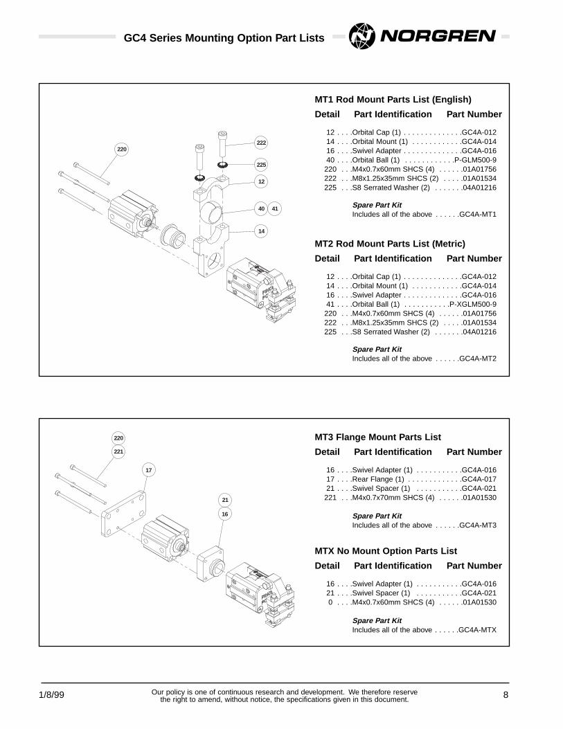
GC4 Series Mounting Option Part Lists
14
40
12
225
222
41
220
MT1 Rod Mount Parts List (English)
Detail Part Identification Part Number
12 . . . .Orbital Cap (1) . . . . . . . . . . . . . .GC4A-01214 . . . .Orbital Mount (1) . . . . . . . . . . . .GC4A-01416 . . . .Swivel Adapter . . . . . . . . . . . . . .GC4A-01640 . . . .Orbital Ball (1) . . . . . . . . . . . .P-GLM500-9
220 . . .M4x0.7x60mm SHCS (4) . . . . . .01A01756222 . . .M8x1.25x35mm SHCS (2) . . . . .01A01534225 . . .S8 Serrated Washer (2) . . . . . . .04A01216
Spare Part KitIncludes all of the above . . . . . .GC4A-MT1
MT2 Rod Mount Parts List (Metric)
Detail Part Identification Part Number
12 . . . .Orbital Cap (1) . . . . . . . . . . . . . .GC4A-01214 . . . .Orbital Mount (1) . . . . . . . . . . . .GC4A-01416 . . . .Swivel Adapter . . . . . . . . . . . . . .GC4A-01641 . . . .Orbital Ball (1) . . . . . . . . . . .P-XGLM500-9220 . . .M4x0.7x60mm SHCS (4) . . . . . .01A01756222 . . .M8x1.25x35mm SHCS (2) . . . . .01A01534225 . . .S8 Serrated Washer (2) . . . . . . .04A01216
Spare Part KitIncludes all of the above . . . . . .GC4A-MT2
MT3 Flange Mount Parts List
Detail Part Identification Part Number
16 . . . .Swivel Adapter (1) . . . . . . . . . . .GC4A-01617 . . . .Rear Flange (1) . . . . . . . . . . . . .GC4A-01721 . . . .Swivel Spacer (1) . . . . . . . . . . .GC4A-021
221 . . .M4x0.7x70mm SHCS (4) . . . . . .01A01530
Spare Part KitIncludes all of the above . . . . . .GC4A-MT3
MTX No Mount Option Parts List
Detail Part Identification Part Number
16 . . . .Swivel Adapter (1) . . . . . . . . . . .GC4A-01621 . . . .Swivel Spacer (1) . . . . . . . . . . .GC4A-0210 . . . .M4x0.7x60mm SHCS (4) . . . . . .01A01530
Spare Part KitIncludes all of the above . . . . . .GC4A-MTX

1/8/99 9Our policy is one of continuous research and development. We therefore reservethe right to amend, without notice, the specifications given in this document.
GC4 Series Mounting Option Part Lists
47
42
46
231
230
43
220
MT4 Rod Mount Parts List (English)
Detail Part Identification Part Number
46 . . . .Orbital Cap (1) . . . . . . . . . . . . . .GC4A-04647 . . . .Orbital Mount (1) . . . . . . . . . . . .GC4A-04716 . . . .Swivel Adapter . . . . . . . . . . . . . .GC4A-01642 . . . .Orbital Ball (1) . . . . . . . . . . . .P-GLM700-5
220 . . .M4x0.7x60mm SHCS (4) . . . . . .01A01756230 . . .M10x1.5x50mm SHCS (2) . . . . .01A01609231 . . .S10 Serrated Washer (2) . . . . . .04A01207
Spare Part KitIncludes all of the above . . . . . .GC4A-MT4
MT5 Rod Mount Parts List (Metric)
Detail Part Identification Part Number
46 . . . .Orbital Cap (1) . . . . . . . . . . . . . .GC4A-04647 . . . .Orbital Mount (1) . . . . . . . . . . . .GC4A-04716 . . . .Swivel Adapter . . . . . . . . . . . . . .GC4A-01643 . . . .Orbital Ball (1) . . . . . . . . . . .P-XGLM700-5220 . . .M4x0.7x60mm SHCS (4) . . . . . .01A01756230 . . .M10x1.5x50mm SHCS (2) . . . . .01A01609231 . . .S10 Serrated Washer (2) . . . . . .04A01207
Spare Part KitIncludes all of the above . . . . . .GC4A-MT5

1/8/99 10Our policy is one of continuous research and development. We therefore reservethe right to amend, without notice, the specifications given in this document.
2
1
200
201
400
GC4 Series Proximity Sensing Part Lists
Proximity Sensing Parts List
Detail Part Identification Part Number
1 . . . .Sensor Housing (1) . . . . . . . . . .GC4AS0012 . . . .Target (1) . . . . . . . . . . . . . . . . .GC4AS002
2200 . . .Status Controller (1) . . . . . . . .GC4AS200201 . . .M5x0.8x20mm LH Cap Screw . .01A02040400 . . .Sensor Label . . . . . . . . . . . . . .GC4AS400
Sensor AssemblyIncludes all of the above . . . . . . .GC4-PS1
Proximity Sensing Parts List
Detail Part Identification Part Number
1 . . . .Sensor Housing (1) . . . . . . . . . .GC4AT0012 . . . .Target (1) . . . . . . . . . . . . . . . . .GC4AT002
200 . . .Status Controller (1) . . . . . . . . .GC4AT200201 . . .M5x0.8x20mm LH Cap Screw . .01A02040400 . . .Sensor Label . . . . . . . . . . . . . . .GC4AT400
Sensor AssemblyIncludes all of the above . . . . . . .GC4-PS2
Attention: Make sure wires do not get pinched between the housing and gripperbody when replacing the status controller assembly. Failure to do so may cause permanent damage.

1/8/99 11Our policy is one of continuous research and development. We therefore reservethe right to amend, without notice, the specifications given in this document.
GC4 Series Installation & Maintenance
Field changing of tips:
3936
22335 39
22
19 20
226
23 24
1. Remove upper and lower lock nut #226.2. Remove upper and lower metric hex bolt
#223.3. Change the tip #19 (single) or #20 (double).4. Replace bolt and lock nut. Torque bolt to
360 in/lb (41 N•m).
Field Changeable Tips and Tip Inserts
These two features help make the GC4 Series of grippers adaptable to practically any sheet metal material handling application. Tips can be changed from single to double or vice versa. The tip inserts can be used bythemselves, making them fully adjustable, or with spacers designed for specific part thicknesses. Page G-2 showsthe tip insert and the tip spacer options available for the GC4 Series gripper. Follow the procedures below tochange tips, tip inserts, or tip spacers.
TYP. MIN. TIP ADJUSTMENT: 0.00MAX. TIP ADJUSTMENT: .20 [5.1]
MAX. TIP ADJUSTMENT: .25 [6.3]MIN. TIP ADJUSTMENT: 0.00
When used without the optional tip spacers, tip inserts are fully adjustable. Part thickness should not vary bymore than .040 in. Beyond that, the inserts must be adjusted to accomodate the thickness of the part. Follow theprocedure below to adjust the tip inserts.
Adjusting Tip Inserts
NOTE: With the gripper’s jaws in their closed position, the inserts may bemanually adjusted. Refer to Figures A and B.
1. With the tip inserts backed off, adjust the concave insert wheredesired and lock into place.
2. Place the part between the two inserts and adjust the convexinsert by hand until both the concave and convex inserts are incontact with the part.
3. Remove the part, then depending on the softness of the metal,advance the convex inserts one or two rotations and lock intoplace. Torque lock nuts to 190 in/lb [21N/m]. For double tipunits, this last adjustment should be made with each convexinsert a little at a time so the part remains level when the twoinserts are locked into place.
Field changing of tip inserts:
1. Remove lock nut from upper and lower inserts, then screw out the inserts #35, #36or #39 from the tips #19 (single) or #20 (double).
2. Thread new inserts into tips. Torque lock nuts to 190 in/lb [21N/m].Note: If spacers #22, #23, #24 are being used, make sure all spacers match incolor. Refer to page G-2 for recommendations.
3. If used without spacers, follow the procedure below to properly adjust the inserts tothe part thickness.
Figure A
Figure B

GC Series
3/15/99 12Our policy is one of continuous research and development. We therefore reservethe right to amend, without notice, the specifications given in this document.
Tip Insert Options
.31 [7.9]
.25
1.24 [31.4]
.31 [7.9]
.25
1.24 [31.4]
.31 [7.9]
.51 [13.0] .51 [13.0] .51 [13.0]
1.24 [31.4]
.25
.51 [13.0] .51 [13.0].51 [13.0]FLATSFLATS
M8x1.25 THD.M8x1.25 THD.M8x1.25 THD.
OPTION A OPTION B
CONVEX INSERT X4-PT11 CONCAVE INSERT X4-PT12 CARBIDE STEEL INSERTX4-PT5
Single and Double Tip Insert Parts List
Detail Part I.D. Part No. Single DoubleTip QtyTip Qty
35 . . . . . Option A Insert (convex) . . X4-PT11............1 . . . . . . 2
36 . . . . Option A Insert (concave) . X4-PT12............1 . . . . . . 2
39 . . . . . Option B Insert (carbide) . . X4-PT5 ............2 . . . . . . 4
40 35
41 39
35
36
39
39
Tip Insert Options
Single and Double Flange Tip Insert Parts List
Detail Part I.D. Part No. Single DoubleTip QtyTip Qty
40 . . . . Option A Insert (concave) GC4B-031 ..........1 . . . . . . 2for Flange Weld Guard
35 . . . . . Option A Insert (convex) . . X4-PT11............1 . . . . . . 2
41 . . . . Option B Insert (carbide). GC4B-032 ..........1 . . . . . . 2for Flange Weld Guard
39 . . . . . Option B Insert (carbide) . . X4-PT5 ............1 . . . . . . 2

1/8/99 13Our policy is one of continuous research and development. We therefore reservethe right to amend, without notice, the specifications given in this document.
GC4 Series Installation & Maintenance
Field changing arms:1. Loosen two (2) flathead screws #215 and
remove weld cover #15.2. Remove the two (2) socket head cap screws
#218, the one (1) socket head cap screw #219and side plate #2 (side plate shown withoutcover).
3. Remove guide block #8 and slide off arm #3.4. Replace arm and guide block, making sure the
bumper is properly seated, replace side plate,the two (2) #218 socket head cap screws andthe one (1) #219 socket head cap screw.Torque the #218 screws to 90 in/lb (10 N/m)and the #219 screw to 75 in/lb (9 N/m).
Field changing bumpers to changehead type:1. Loosen (no need to remove) the two flathead
screws #215.2. Tip and and remove bumper(s) #402.3. Replace with new bumper (see Note below).4. Retighten 2 flathead screws. Torque to 85 in/lb
(9.5 N/m).
NOTE:1. Head Type Options A1, A2 & A3 each use identical bumpers. Refer to page E-1 for kit information and part callouts.
2. Head Type Option D1 uses a single 22° bumper and a single 80° bumper. Refer to page E-2 for kit information and part callouts.
3. Head Type Options L1, L2, L3, U1, U2, & U3 all use a single 0° bumper combined with an opposing 22°, 45° or 80° arm bumper.
Refer to page E-3 for kit information and part callouts.
218
219
2
8
3 15
215
Field Changeable Arms
Field Changeable Head Types
15
215
400 402
403 404
400 402
403 404
1/8/99 14Our policy is one of continuous research and development. We therefore reservethe right to amend, without notice, the specifications given in this document.
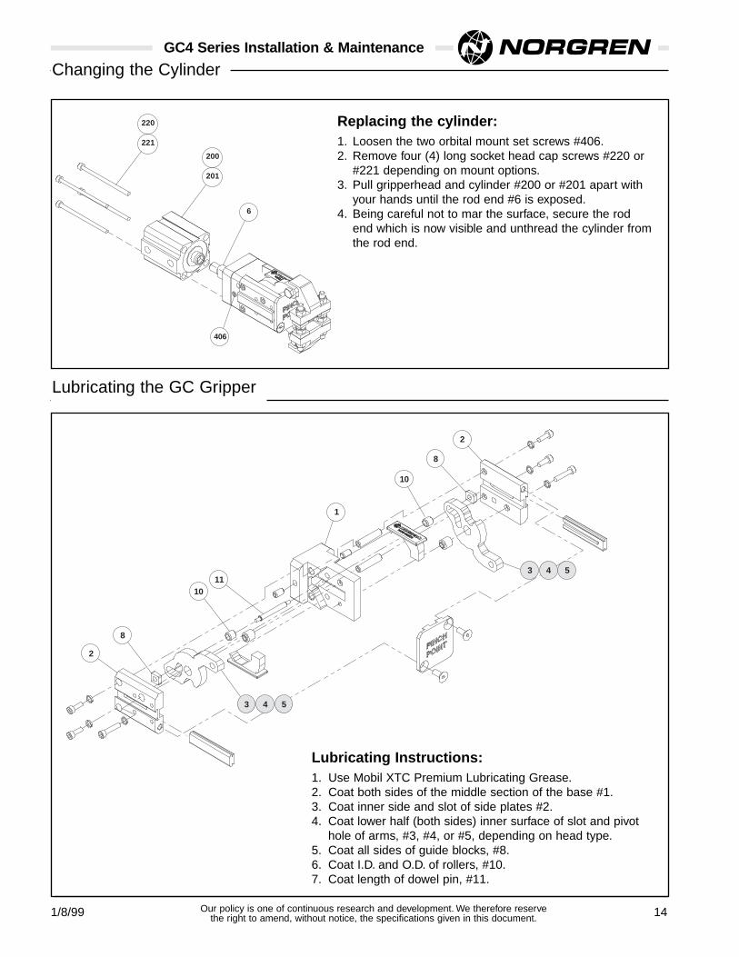
GC4 Series Installation & Maintenance
220
221
6
200
201
406
Replacing the cylinder:1. Loosen the two orbital mount set screws #406.2. Remove four (4) long socket head cap screws #220 or
#221 depending on mount options.3. Pull gripperhead and cylinder #200 or #201 apart with
your hands until the rod end #6 is exposed.4. Being careful not to mar the surface, secure the rod
end which is now visible and unthread the cylinder fromthe rod end.
Changing the Cylinder
Lubricating Instructions:1. Use Mobil XTC Premium Lubricating Grease.2. Coat both sides of the middle section of the base #1.3. Coat inner side and slot of side plates #2.4. Coat lower half (both sides) inner surface of slot and pivot
hole of arms, #3, #4, or #5, depending on head type.5. Coat all sides of guide blocks, #8.6. Coat I.D. and O.D. of rollers, #10.7. Coat length of dowel pin, #11.
2
8
8
11
1
2
3
10
10
4 5
3 4 5
Lubricating the GC Gripper

GC Series
10/98 15Our policy is one of continuous research and development. We therefore reservethe right to amend, without notice, the specifications given in this document.

GC Series
10/98 16Our policy is one of continuous research and development. We therefore reservethe right to amend, without notice, the specifications given in this document.